the chlorine manual - archer · pdf filethe chlorine institute, inc. mission statement the...
TRANSCRIPT
THE CHLORINE INSTITUTE, INC.
2001 L Street, N.W., Suite 506Washington, D.C. 20036
202-775-2790Fax: 202-223-7225
http:// www.CL2.com
THE CHLORINE MANUAL
Sixth Edition

THE CHLORINE INSTITUTE, INC.
MISSION STATEMENT
The Chlorine Institute, Inc. exists to support the chlor-alkali industryand serve the public by fostering the continuous evaluation of andimprovements to safety and the protection of human health and theenvironment connected with the production, distribution and use ofchlorine, sodium and potassium hydroxides, and sodium hypochlorite; andthe distribution and use of hydrogen chloride. The Institute meets thisobligation by maintaining a scientific and technical organization that fullymeets its members’ and publics’ needs and expectations. The Instituteworks with governmental agencies to encourage the use of credible scienceand technology in developing regulations impacting the industry.
American National Standard - February 29, 2000
This Publication has been approved as an American NationalStandard (ANS). Approval of an ANS requires review by The AmericanNational Standards Institute (ANSI) that the requirement for due process,consensus, and other criteria for approval have been met by the standardsdeveloper. Consensus is established when, in the judgement of the ANSIBoard of Standards Review, substantial agreement has been reached bydirectly and materially affected in4erests. Substantial agreement meansmuch more than a simple majority, but not necessarily unanimity. Consensusrequires that all views and objections be considered, and that a concertedeffort be made toward their resolution.
The use of ANSs is completely voluntary; their existence does not in anyrespect preclude anyone, whether he or she has approved the standards ornot, from manufacturing, marketing, purchasing, or using products,processes, or procedures not conforming to the standards. The ANSI doesnot develop standards and will in no circumstances give an interpretation ofany ANS. Moreover, no person shall have the right or authority to issue aninterpretation of an ANS in the name of the ANSI. Requests forinterpretations should be addressed to the secretariat or sponsor whose nameappears on the title page of this standard.
Caution Notice: This ANS may be revised or withdrawn at any time.The procedures of the ANSI require that action bc taken periodically toreaffirm, revise, or withdraw this standard. Purchasers of ANSs may receivecurrent information on all standards by calling or writing the AmericanNational Standards Institute.

i. INTRODUCTION• The Chlorine Manual• Commitment to Responsible® Care• Checklists• References
1. GENERAL INFORMATION 11.1 Chlorine Manufacture 11.2 Chlorine in Transportation 11.3 Other Regulatory Aspects 21.4 Chemical and Physical Properties 31.5 Terminology 31.6 Health Hazards 41.7 Other Hazards 41.8 Containers 5
2. CYLINDERS AND TONCONTIANERS 7
2.1 Container Descriptions 72.2 Container Valves 82.3 Pressure Relief Devices 82.4 Container Shipping 92.5 Container Labeling and Placarding 92.6 Container Handling 92.7 Container Storage 102.8 Container Use 10
3. BULK SHIPPING CONTAINERS 143.1 General 143.2 Tank Cars 143.3 Tank Motor Vehicles 183.4 Portable Tanks 203.5 Tank Barges 20
4. EMERGENCY MEASURES 224.1 General 224.2 Response to a Chlorine Release 224.3 Response to a Fire 224.4 Releases 234.5 Transportation Emergencies 244.6 Disposal of Chlorine 264.7 Absorption Systems 264.8 Emergency Kits and Recovery
Vessels 264.9 Reporting 27
5. EMPLOYEE TRAINING ANDSAFETY 28
5.1 Employee Training 285.2 Personal Protective Equipment 285.3 Confined Space Entry 295.4 Personal Exposure Monitoring 29
6. MEDICAL ASPECTS AND FIRSTAID 30
6.1 Hazards to Health 306.2 Preventive Health Measures 306.3 First Aid 316.4 Medical Management of
Chlorine Exposures 31
7. ENGINEERING DESIGN ANDMAINTENANCE 34
7.1 Structures 347.2 Ventilation 347.3 Material for Processing
Equipment 357.4 Electrolyzers (Cells) 357.5 Chlorinators 367.6 Vaporizers 367.7 Support Equipment 367.8 Piping Systems for Dry Chlorine377.9 Piping Systems for Wet Chlorine397.10 Stationary Storage 397.11 Equipment Maintenance 397.12 Chlorine Neutralization 40
8. KEY REGULATIONS ANDCODES 41
8.1 Occupational Safety and HealthRegulations 29 CFR 41
8.2 Navigation and Navigable WaterRegulations 33 CFR 42
8.3 Environmental Regulations40 CFR 42
8.4 Shipping Regulations 46 CFR (WaterTransportation) 43
8.5 Transportation Regulations49 CFR 44
8.6 Fire Codes 45
TABLE OF CONTENTS

9. TECHNICAL DATA 469.1 General 469.2 Atomic and Molecular Properties 469.3 Chemical Properties 469.4 Physical Properties 47
10. SELECTED REFERENCES 5610.1 U.S. Government Regulations
and Specifications 5610.2 Canadian Regulations 5610.3 Chlorine Institute References 5610.4 American Conference of
Governmental IndustrialHygienists 58
10.5 American Society ofMechanical Engineers 58
10.6 American Society for TestingMaterials 58
10.7 American Water WorksAssociation 59
10.8 Association of AmericanRailroads 59
10.9 Compressed Gas Assn. 5910.10 National Academy of Sciences 5910.11 National Fire Protection
Association 5910.12 National Institute of
Occupational Safety and Health 5910.13 National Safety Council 5910.14 NSF International 5910.15 Water Environment Federation 5910.16 World Health Organization 5910.17 Chemical Industry Inst. Of
Toxicology 5910.18 Other References 59
ILLUSTRATIONS
Fig. 2.1 Chlorine Cylinders 7Fig. 2.2 Chlorine Ton Container 7Fig. 2.3 Standard Cylinder Valve 8Fig. 2.4 Standard Ton Container Valve 8Fig. 2.5 Standard Fusible Plug
for Ton Containers 8Fig. 2.6 Lifting Beam for Handling
Chlorine Ton Containers 9Fig. 2.7 Yoke & Adapter
Type Connection 12Fig. 3.1 Chlorine Tank Car 14Fig. 3.2 Valve Arrangement & Manway 15Fig. 3.3 Standard Angle Valve 15Fig. 3.4 Excess-Flow Valve 16Fig. 3.5 Standard Pressure Relief Device 16Fig. 3.6 Chlorine Tank Truck 19Fig. 3.7 Chlorine Barge 21Fig. 4.1 Chlorine Institute
Emergency Kit Afor Chlorine Cylinders 27
CHARTS
Fig. 9.1 Vapor Pressureof Liquid Chlorine 50
Fig. 9.2 Temperature-Density Relationof Liquid Chlorine 51
Fig. 9.3 Equilibrium Solubilityof Chlorine in Water 52
Fig. 9.4 Volume-Temperature Relationof Liquid Chlorine in a ContainerLoaded to its Authorized Limit 53
Fig. 9.5 Solubillity of Waterin Liquid Chlorine 54
Fig. 9.6 Solubility of Water inLiquid Chlorine 55
TABLES
2.1 Container Dimensionsand Weights 9
4.1 Recommended Alkalline Solutionsfor Absorption 26
T
THE CHLORINE MANUAL
he widespread use of chlorine and the accompanying demand for reliableinformation on recognized procedures for the safe handling of chlorine resultedin the publication of the first Chlorine Manual by the Chlorine Institute in 1947.
Subsequent editions have been published in 1954, 1959, 1969, and 1986. The Chlorine Manual is a compendium of information available to the Institute basedon experience with materials, equipment, regulations and practices contributing to thesafe handling, storage, shipment and use of chlorine. Important properties of chlorineare included. There is a brief section on the production of chlorine, as well as methodsof dealing with potential emergencies. The reference section will provide to readers sources for more detailed informationabout matters on which the text material is based. Where questions remain -- onprotective provisions or procedures, for example -- a chlorine user should consult theproducer or supplier of the product or the chlorine handling equipment, or contact theChlorine Institute. Annually, the Institute updates its publications catalog. This free catalog can beobtained by contacting the Publications Department of the Institute.
The information contained in the catalog also is available through the Institute’s Internetwebsite – http://www.cl2.com.
RESPONSIBLE CARE®
he Institute is a Chemical Manufacturers Association (CMA) Responsible Care®
Partnership Association. In this capacity, the Institute is committed to: Fosteringthe adoption by its members of the Codes of Management Practices; facilitating
their implementation; and encouraging members to join the Responsible Care® initiativedirectly.
Chlorine Institute members who are not CMA members are encouraged to follow theelements of similar responsible care programs through other associations such as theNational Association of Chemical Distributors (NACD) Responsible Distribution Programor the Canadian Chemical Manufacturers Association's Responsible Care® program.
INTRODUCTIONi
T

CHECKLISTS
The Chlorine Institute is adding checklists to appropriate pamphlets to assist itsmembers and non-members in self audits or other reviews. These checklists arebeing added to new and existing pamphlets beginning in 1996.
Because the Chlorine Manual only summarizes some of the information contained inthe other pamphlets, the reader should refer to the specific pamphlets and theirchecklists. These checklists are designed to emphasize major topics and highlight thekey recommendations for someone who has already read and understood thepamphlets.
The Chlorine Institute encourages the use of the pamphlets and their checklists.
REFERENCES
hlorine Institute publications referenced in this publication are referred to bypamphlet number, drawing number, or by condensed name if no number exists.
At the beginning of Section 10 – “Selected References”, completeinformation about the Institute publications is provided. Other sources are referenced inthis publication in the following manner: (Reference 10.4.1). Section 10 providesinformation on each of these references. In most cases, an address also is provided.
The Institute updates its publications catalog annually. This free catalog can beobtained by downloading from the CI website or contacting the Institute PublicationsDepartment, 2001 L Street, NW, Suite 506, Washington, DC 20036:
Ph: 202-775-2790Fax: 202-223-7225
Web: http://www.CL2.com
T
C

1
1.1 Chlorine Manufacture
Most chlorine is manufacturedelectrolytically by the diaphragm, themercury or the membrane cell process. Ineach process a salt solution is electrolyzedby the action of direct electric current whichconverts chloride ions to elemental chlorine.Chlorine production for 1996 in shorttons/year is estimated to be as follows:world -47 million, U.S. -13 million, Canada -1.2 million, and Mexico -0.4 million.
In the diaphragm cell process, sodiumchloride brine is electrolyzed to producechlorine at the positive electrode (anode)while sodium hydroxide (caustic soda) andhydrogen are produced at the negativeelectrode (cathode). In order to prevent thereaction of sodium hydroxide and hydrogenwith the chlorine, the anode and cathodechambers are separated by a porousdiaphragm.
In the mercury cell process recirculatingmercury serves as the cathode. Chlorine isremoved from the gas space above theanodes and elemental sodium is formed atthe cathode. The sodium amalgamates withthe mercury. The sodium-mercury amalgamthen flows to a decomposer where it isreacted with purified water to producesodium hydroxide and hydrogen with themercury being recirculated.
The membrane cell processelectrolyzes sodium chloride brine toproduce chlorine at the positive electrode(anode) while sodium hydroxide andhydrogen are produced at the negativeelectrode (cathode). An ion selectivemembrane prevents the reaction of sodiumhydroxide and hydrogen with chlorine.
Chlorine is also produced in a numberof other ways, for example, by electrolysisof potassium chloride brine in membraneand mercury cells with co-production ofpotassium hydroxide; by electrolysis ofmolten sodium or magnesium chloride tomake elemental sodium or magnesium
metal; by electrolysis of hydrochloric acid;and by non-electrolytic processes. Furtherinformation on electrolyzers and electrolyticmethods can be found in Section 7.4 of thispamphlet. An additional reference is theKirk-Othmer Encyclopedia of ChemicalTechnology which contains a section onchlorine and sodium hydroxide (Reference10.18.7).
1.2 Chlorine in Transportation
1.2.1 General
Chlorine is normally shipped as aliquefied compressed gas. Thetransportation of chlorine in all modes oftransportation is controlled by regulations. Itis the responsibility of each person shippingor transporting chlorine to know and tocomply with all applicable regulations.
1.2.2 United States
ln the U. S., chlorine in commerce isregulated by the Department ofTransportation (DOT). Chlorine is a Class 2,Division 2.3 poison gas and is assigned apoison Zone B inhalation hazard material.For land transportation and for carriage ofcontainers by water, DOT regulationsappear in Title 49 Code of FederalRegulations (CFR). DOT regulationscovering tank barges appear in Title 33 and46 CFR. See Section 8. Many states haveadopted regulations substantially the sameas DOT regulations.
In addition there may be localrequirements.
1.2.3 Canada
In Canada, chlorine is classified as aClass 2, Division 2.3 poison gas with asecondary classification of Class 5, Division5.1 oxidizer. Regulations are issued byTransport Canada (TC) for all modes of
1 GENERAL INFORMATION

2
transportation under the “Transportation ofDangerous Goods Act and Regulations”TDG).
Many regulations are in accordance withthose issued by the U.S. DOT, but someminor differences exist. The concernedreader may obtain additional informationfrom Canada Communications Group, 45Sacré-Coeur Boulevard, Hull, Quebec,Canada, K1A 0S9 or directly from theCanadian government.
1.2.4 Mexico
In Mexico, chlorine is classified as aClass 2, Division 2.3 poison gas with asecondary classification of Class 5.1Oxidizer.
Regulations for the transportation ofhazardous materials are issued as part ofRegulations for Surface Transportation ofHazardous Materials and Wastes, April 7,1993 as published in the Diario Official de IaFederacion. Most of the regulations are inaccordance with those issued by the U.S.DOT.
1.2.5 Other Countries
International shipments of chlorine mustmeet the requirements of the country oforigin and the country of destination.Generally, hazardous material regulationsthroughout the world are similar as a resultof standardized regulations providedthrough the United Nations andimplemented by intermodal U.N. agencies.For instance, the International MaritimeOrganizations (IMO) publishes theInternational Maritime Dangerous Goods(IMDG) Code. Shipments of chlorinecontainers by vessels meeting thestandards of the IMDG Code are acceptedin most countries. There are similar U.N.agencies and recommendations for road,rail and air transportation systems. TheUnited Nations designation for chlorine isU.N. 1017.
1.3 Other Regulatory Aspects
Chlorine manufacturers, packagers, andmost consumers are subject to workplaceregulations pertaining to chlorine throughoutmost of the world.
1.3.1 United States
The Department of Labor’s (DOL)Occupational Safety and HealthAdministration (OSHA) issues regulationsinvolved with worker protection.Environmental regulations are issued by theEnvironmental Protection Agency (EPA).When used as a disinfectant (water orwaste treatment), chlorine is considered tobe a fungicide and is subject to EPAregulations issued under the FederalInsecticide, Fungicide and Rodenticide Act(FIFRA). In addition, many state or localagencies now require that chlorine used inthe drinking water treatment industry becertified to meet ANSI/NSF Standard 60(Reference 10.14.1).
1.3.2 Canada
Workplace regulations are issuedthrough the Workplace Hazardous MaterialsInformation System (WHMIS) and byindividual provinces. Environmentalregulations are primarily addressed throughprovincial governments in conjunction withEnvironment Canada.
1.3.3 Other Countries
Similar regulations apply in many othercountries. Various numbering systems ofchemicals apply in certain regulatoryprograms.
For chlorine, the following arepertinent:• The Chemical Abstracts Service (CAS)
number is CAS 7782-50-5.• The Registry of Toxic Effects of Chemical
Substances (RTECS) number assignedin the U.S. by the National Institute forOccupational Safety and Health isF02100000.

3
1.4 Chemical and Physical Properties
Chlorine is an element and a memberof the halogen family. Chlorine gas or liquidis not explosive or flammable, but it willsupport combustion. Both the liquid and gasreact with many substances. Chlorine isonly slightly soluble in water. The gas has acharacteristic, penetrating odor, a greenishyellow color and is about two and one-halftimes as heavy as air. Thus, if chlorineescapes from a container or system, it willtend to seek the lowest level in the buildingor area in which the leak occurs.
Liquid chlorine is amber in color and isabout one and one-half times as heavy aswater. At atmospheric pressure, it boils atabout –29oF(-34oC) and freezes at about -1500F (-101o C).
One volume of liquid chlorine, whenvaporized, yields about 460 volumes of gas.
Although dry chlorine (gas or liquid)normally does not react with or corrodesome metals such as copper or carbonsteel, it is strongly reactive (stronglycorrosive) when moisture is present. SeeSection 9.3.3.2.
1.5 Terminology
1.5.1 Chlorine
The chemical element in whatever stateor condition it may exist under theconditions being considered. Chlorine’ssymbol is Cl, its atomic number is 17 and itsatomic weight is 35.453. Chlorine almostalways exists as a molecule with twochlorine atoms bound together as Cl2. Itsmolecular weight is 70.906.
1.5.2 Liquid Chlorine
The element, chlorine, in the liquid state.[The term “Iiquid chlorine” sometimes isused incorrectly to describe a hypochloritesolution. This is a misuse of the term andthe Institute discourages its use.]
1.5.3 Chlorine Gas
The element, chlorine, in the gaseousstate.
1.5.4 Dry Chlorine
Liquid or gaseous chlorine with its watercontent dissolved in solution. The solubilityof water in chlorine varies with temperatureand is shown in Figures 9.5 and 9.6. SeePamphlet 100. [The term “dry chlorine”sometimes is used incorrectly to describe adry chlorinating compound (usually calciumhypochlorite or the chloroisocyanurates).This is a misuse of the term and the Institutediscourages its use.]
The following are examples usingFigures 9.5 and 9.6:
• Chlorine with a water content of 30 ppmat a temperature of 50o F (10o C) is dry. Ifthis same chlorine (30 ppm) were at atemperature of -4o F (-20oC) the chlorine iswet.• Chlorine at 41o F (5o C) is dry if thewater content does not exceed 100 ppm.
1.5.5 Wet Chlorine
Liquid or gaseous chlorine with itswater content exceeding the amount that isdissolved in solution. See Pamphlet 100.Chlorine is not wet just because it is in theliquid state.
1.5.6 Moist Chlorine
Synonymous with wet chlorine.
1.5.7 Saturated Chlorine Gas
Chlorine gas in such condition that theremoval of any heat or an increase inpressure will cause some portion of it tocondense to a liquid. [This term should notbe confused with wet or moist chlorine.]
1.5.8 Saturated Chlorine Liquid
Chlorine liquid in such condition thatthe addition of any heat or a decrease in

4
pressure will cause some portion of thechlorine to vaporize to a gas. [This termshould not be confused with wet or moistchlorine.]
1.5.9 Chlorine Solution (Chlorine Water)
A solution of chlorine in water (forsolubility of chlorine in water see Fig. 9.3).[The term “chlorine solution” sometimes isused incorrectly to describe hypochloritesolutions. This is a misuse of the term andthe Institute discourages its use.]
1.5.10 Liquid Bleach
A solution of hypochlorite, usually sodiumhypochlorite. This term rather than “liquidchlorine” should be used to describe a liquidhypochlorite product. See Section 1.5.2.
1.5.11 Container
In this publication, a container is apressure vessel authorized by an applicableregulatory body for the transport of chlorine.It does not include pipelines or stationarystorage tanks specifically designed andinstalled for transfer or storage.
1.5.12 Filling Density
By DOT regulation, the weight ofchlorine that is loaded into a container maynot exceed 125% of the weight of water at60o F (15.6oC) that the container will hold.
1.5.13 Sodium Hydroxide
Normally the co-product produced as asolution when chlorine is generated throughthe electrolytic decomposition of sodiumchloride solution. Sodium hydroxide isfrequently referred to as caustic soda.
1.5.14 Potassium Hydroxide
A co-product produced as a solutionwhen chlorine is generated through theelectrolytic decomposition of potassiumchloride salt solution. Potassium hydroxide
is frequently referred to as caustic potash.
1.6 Health Hazards
Chlorine gas is primarily a respiratoryirritant. In sufficient concentration, the gasirritates the mucous membranes, therespiratory tract and the eyes. In extremecases difficulty in breathing may increase tothe point where death can occur fromrespiratory collapse or lung failure. Thecharacteristic, penetrating odor of chlorinegas usually gives warning of its presence inthe air.
Also, at high concentrations, it is visibleas a greenish yellow gas. Liquid chlorine incontact with skin or eyes will causechemical burns and/or frostbite. See Section6.
The American Conference ofGovernmental Industrial Hygienists (ACGIH)(Reference 10.4.1) has established athreshold limit value time-weighted average(TWA) of exposure to chlorine at 0.5 ppm.The TWA is based on a normal workschedule of 8 hours/day and 40 hours/week.ACGIH has established a threshold limitvalue short-term exposure limit (STEL) of 1ppm for exposure to chlorine. The STEL isdefined as a 15-minute TWA exposure.
In 1994, the National Institute forOccupational Safety and Health reduced itsImmediately Dangerous to Life or Health(IDLH) concentration for chlorine to 10 ppm(Reference 10.12.1).
1.7 Other Hazards
1.7.1 Fire
Chlorine is neither explosive nor flammable;however, chlorine will support combustion.
1.7.2 Chemical Action
Chlorine has a very strong chemicalaffinity for many substances. It will reactwith many inorganic and organiccompounds, usually with the evolution ofheat. Chlorine reacts with some metalsunder a variety of conditions. See Section

5
9.3.3.2.
1.7.3 Corrosive Action on Steel
At ordinary temperatures, dry chlorine,either liquid or gas, does not corrode steel.Wet chlorine is highly corrosive because itforms hydrochloric and hypochlorous acids.Precautions should be taken to keepchlorine and chlorine equipment dry. Piping,valves and containers should be closed orcapped when not in use to keep outatmospheric moisture. If water is used on achlorine leak the resulting corrosiveconditions will make the leak worse.
1.7.4 Volumetric Expansion
The volume of liquid chlorine increaseswith temperature. Precautions should betaken to avoid hydrostatic rupture of piping,vessels, containers or other equipment filledwith liquid chlorine. See Figure 9.4.
1.7.5 Specific Manufacturing and UseHazards
1.7.5.1 Hydrogen
Hydrogen is a co-product of all chlorinemanufactured by the electrolysis of aqueousbrine solutions. Within a known concentra-tion range, mixtures of chlorine andhydrogen are flammable and potentiallyexplosive. The reaction of chlorine andhydrogen can be initiated by direct sunlight,other sources of ultraviolet light, staticelectricity, or sharp impact.
1.7.5.2 Nitrogen Trichloride
Small quantities of nitrogen trichloride,an unstable and highly explosivecompound, can be produced in themanufacture of chlorine. When liquidchlorine containing nitrogen trichloride isevaporated, the nitrogen trichloride mayreach hazardous concentrations in theresidue. See Pamphlets 21 and 152.
1.7.5.3 Oils and Grease
Chlorine can react, at times explosively,with a number of organic materials such asoil and grease from sources such as aircompressors, valves, pumps, oil-diaphragminstrumentation, as well as wood and ragsfrom maintenance work.
1.8 Containers
1.8.1 Container Specifications
Chlorine shipping containers other thanbarges must comply with the authorized,numbered specification under which theyhave been fabricated. New containers mustbe fabricated according to the currentspecifications and the applicableregulations. Older containers maybecontinued in service in accordance withapplicable regulations. Plans andspecifications for construction of bargesmust be approved by the U.S. Coast Guardor the Canadian Coast Guard.
1.8.2 Container Types
• Cylinders (150-pound or less)
Fabricated to DOT (or TC) specification3A480 or 3AA480. See Section 2. Cylindersconforming with some older specificationsmay still be used. Special cylindersconforming to DOT (or TC) specification3BN480 or 3E1800 are applicable forspecialized laboratory use.
• Ton Containers
Fabricated to DOT (or TC) specification106A500X. See Section 2. Ton containersconforming with older specifications maystill be used.
• Portable Tanks
Portable tanks fabricated to DOTSpecification 51 with special requirementsfor chlorine.

6
• Tank Multi-Unit (TMU) Cars
Specially built railroad cars with cradlesto carry 15 one-ton containers. The TMUcar is nearly obsolete and will not beconsidered further in this manual.
• Tank Cars
Railroad tank cars fabricated to DOT(or TC) specifications 105J500W or105S500W. See Section 3.2. Cars built tosome older specifications may still beused.
• Tank Motor Vehicles
Tank trailers complying with DOTspecification MC 331. See Section 3.3.Trailers conforming to ICC specificationMC 330 may still be used.
• Tank Barges
Barges containing chlorine tanks,usually four. See Section 3.5.
1.8.3 Container Similarities
Containers are similar in the followingaspects:
• They are constructed of steel.
• They are inspected and pressuretested at regular intervals as required byapplicable regulations.
• They are equipped with one or morepressure relief devices.
• They are marked, labeled andplacarded as required by applicableregulations.
• They are all built to meet federalgovernment specifications.
7
2.1 Container Descriptions
2.1.1 General
Cylinders and ton containershave many similarities in theway in which they arehandled and many users ofcylinders also use toncontainers. Therefore, theyare considered together inthis section. The terms“cylinder,’’ ‘‘ton cylinder,’’ or“drum” should not be used todescribe the ton container.Emergency equipment forhandling ton containers isdifferent from that used forcylinders and confusion canbe avoided if the properterms are used.
2.1.2 Cylinders
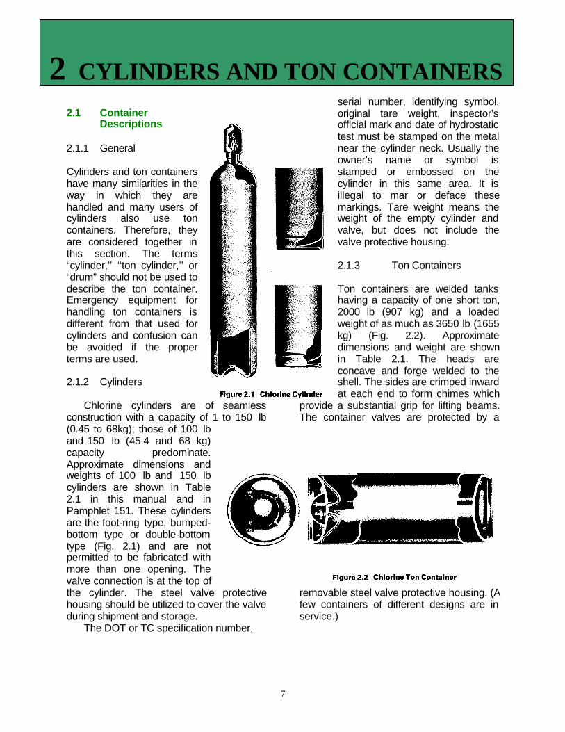
Chlorine cylinders are of seamlessconstruction with a capacity of 1 to 150 lb(0.45 to 68kg); those of 100 lband 150 lb (45.4 and 68 kg)capacity predominate.Approximate dimensions andweights of 100 lb and 150 lbcylinders are shown in Table2.1 in this manual and inPamphlet 151. These cylindersare the foot-ring type, bumped-bottom type or double-bottomtype (Fig. 2.1) and are notpermitted to be fabricated withmore than one opening. Thevalve connection is at the top ofthe cylinder. The steel valve protectivehousing should be utilized to cover the valveduring shipment and storage.
The DOT or TC specification number,
serial number, identifying symbol,original tare weight, inspector’sofficial mark and date of hydrostatictest must be stamped on the metalnear the cylinder neck. Usually theowner’s name or symbol isstamped or embossed on thecylinder in this same area. It isillegal to mar or deface thesemarkings. Tare weight means theweight of the empty cylinder andvalve, but does not include thevalve protective housing.
2.1.3 Ton Containers
Ton containers are welded tankshaving a capacity of one short ton,2000 lb (907 kg) and a loadedweight of as much as 3650 lb (1655kg) (Fig. 2.2). Approximatedimensions and weight are shownin Table 2.1. The heads areconcave and forge welded to theshell. The sides are crimped inwardat each end to form chimes which
provide a substantial grip for lifting beams.The container valves are protected by a
removable steel valve protective housing. (Afew containers of different designs are inservice.)
2 CYLINDERS AND TON CONTAINERS

8
Note: The Instituterecommends that all pre-1936 ton containersmanufactured by theAmerican Welding ServiceCompany not be used inchlorine service.
The DOT or TCspecification number, thematerial and claddingmaterial (if any), the owner’sor the builder’s identifyingsymbol and serial number,the inspector’s mark, the testdate(s), and the watercapacity must all bestamped into the chime atthe valve end. Thisinformation also may bestamped on a brass platesecured to the tank headopposite the valve end. It isillegal to mar or deface thesemarkings. In addition to theabove required markings,the original tare weight isstamped either on the chimeor on the brass plate. Tareweight means the weight ofthe empty container withvalves and fusible plugs, butdoes not include theprotective valve housing.Usually the owner’s name orsymbol is stamped on thecontainer or embossed onthe brass plate.
2.2 Container Valves
2.2.1 CylindersA standard cylinder valve
is shown in Fig. 2.3. Othervalves also may berecommended for chlorineservice. See Pamphlet 17. The valve outletthreads are not standard pipe threads, but
are special straight threads(designated as 1.030 inch – 14NGO-RH-EXT). See Section 2.8.5 fordetails on recommendedconnections.
Cylinder valves are equippedwith a fusible metal pressure reliefdevice or, as more commonlynamed, a fusible plug. See Section2.3.1.
2.2.2 Ton Containers
Each ton container is equippedwith two identical valves near thecenter of one end. These valves arestandard ton container valves (Fig.2.4). See Drawing 110. They aredifferent from the standard cylindervalve in that they have no fusiblemetal plug and usually have a largerinternal passage. Other valves alsomay be recommended for chlorineservice. See Pamphlet 17. Eachvalve connects to an internaleduction tube (Fig. 2.2).
2.3 Pressure Relief Devices
2.3.1 Cylinders
Cylinder valves are equippedwith a fusible metal relief device orfusible plug. Most valves have athreaded plug containing the fusiblemetal screwed into a tapped hole inthe valve body, below the valveseat. (A few have fusible metal castdirectly into a threaded hole in thevalve body.) The fusible metal isdesigned to yield or melt between1580F and 1650F (700C and 740C) torelieve pressure and preventcontainer rupture if exposed to fireor other high temperature. The reliefdevice is activated only in the event
of a temperature increase.
9
2.3.2 Ton ContainersAll ton containers are equipped with
fusible metal pressure relief devices (Fig.2.5). Most have six fusible metal plugs,three in each end, spaced 120° apart. Thefusible metal is designed to yield or meltbetween 1580F and 1650F (700C and 740C)to relieve pressure and prevent rupture ofthe container in case of fire or otherexposure to high temperature. The reliefdevice is activated only in the event of atemperature increase.
2.4 Container Shipping
2.4.1 Cylinders
Cylinders may be shipped by highway,rail or water. Highway shipments may betruckload or less-than-truckload (LTL) lots.Suitable restraints are necessary to preventcylinders from shifting during transportation.See Pamphlet 76.
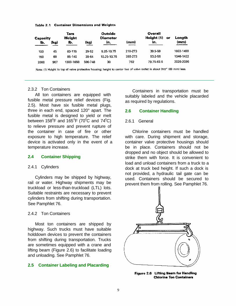
2.4.2 Ton Containers
Most ton containers are shipped byhighway. Such trucks must have suitableholddown devices to prevent the containersfrom shifting during transportation. Trucksare sometimes equipped with a crane andlifting beam (Figure 2.6) to facilitate loadingand unloading. See Pamphlet 76.
2.5 Container Labeling and Placarding
Containers in transportation must besuitably labeled and the vehicle placardedas required by regulations.
2.6 Container Handling
2.6.1 General
Chlorine containers must be handledwith care. During shipment and storage,container valve protective housings shouldbe in place. Containers should not bedropped and no object should be allowed tostrike them with force. It is convenient toload and unload containers from a truck to adock at truck bed height. If such a dock isnot provided, a hydraulic tail gate can beused. Containers should be secured toprevent them from rolling. See Pamphlet 76.

10
2.6.2 Cylinders
Cylinders can be moved about in a plantarea using a properly balanced hand truck.The truck should have a clamp or chain two-thirds of the way up the cylinder wall to holdthe cylinder in place. If cylinders must beelevated by hoist, a specially designedcradle or carrier should be used. Slings andmagnetic devices are unacceptable.Cylinders must not be lifted by the valveprotective housing because the neck ring towhich the housing is attached is notdesigned to carry the weight of the cylinder.
2.6.3 Ton Containers
Ton containers are typically movedusing a monorail or crane with a lifting beam(Fig. 2.6). See Drawing 122. They can berolled on rails or roller conveyers designedfor this purpose. If a fork lift truck is used,the ton container must be adequatelyrestrained to prevent it from falling off,particularly when the truck changesdirection. The fork lift truck must be rated tohandle the gross weight of the container(3300-3650 lb or 1500-1655 kg).
2.7 Container Storage
Containers may be stored indoors oroutdoors. If stored indoors, the storage areashould comply with the provision of Sections7.1 and 7.2. If stored outdoors, the storagearea should be clean so that accumulatedtrash or other combustible material does notpresent a fire hazard. Containers should notbe stored near elevators or ventilatingsystems because dangerous concentrationsof gas may spread rapidly if a leak occurs.All containers should be stored to minimizeexternal corrosion. If standing water cancollect around the containers, suitableplatforms or supports should be provided.Provisions should be made to permit routineinspection of all containers. Containers
should not be stored where heavy objectscould fall on them or where vehicles couldstrike them. Because chlorine is heavierthan air, subsurface storage areas shouldbe avoided. Access to storage byunauthorized persons should be controlled.
Exposure of containers to flame, intenseradiant heat or to steam lines must beavoided. If the metal in the vicinity of thefusible plug reaches approximately 1580F(700C), the fusible metal plug is designed tomelt and chlorine will be released.
Full and empty containers should bestored separately. Even though a containeris empty, the valve outlet cap(s) and thevalve protective housing should be in place.Cylinders should be stored in an uprightposition. OSHA regulations require cylindersbe properly secured to prevent toppling. Toncontainers should be stored on their sidesabove the ground or floor on steel orconcrete supports. In earthquake zones,special storage consideration should bemade.
Chlorine containers should besegregated from flammable and oxidizingmaterials and from materials such asammonia, hydrocarbons and other materialswhich are reactive with chlorine. Easyaccess to containers is important in theevent of a leak.
2.8 Container Use
2.8.1 General
Before connecting or disconnecting acontainer, the operator should make surethat all safety and emergency equipment isavailable and operable. Containers andvalves must not be modified, altered, orrepaired by anyone other than the owner.
2.8.2 Gas Discharge
Cylinders are normally secured in theupright position and deliver chlorine as gas.Ton containers chocked in a horizontalposition and with the valves in a vertical line(Fig. 2.2) deliver gas from the upper valve
11
and liquid from the lower valve SeePamphlet 17.
The flow of chlorine gas from acontainer depends on the internal pressurewhich, in turn, depends on the temperatureof the liquid chlorine. In order to withdrawgas, liquid chlorine must vaporize. Unlessenough external heat is available, thetemperature of the chlorine will be reducedas the liquid vaporizes and, consequently,the pressure in the container will fall. At lowwithdrawal rates, surrounding air mayprovide sufficient heat so that the pressurein the container remains adequate tomaintain a uniform flow. At high withdrawalrates, the temperature and pressure withinthe container may fall because of thecooling effect of vaporization. As thishappens, the rate of flow will graduallydiminish and may even appear to stop,giving a false indication of an emptycylinder.
In humid conditions, condensation willform on the outside of the container. Atexcessive withdrawal rates, the liquid will becooled to such an extent that frost will formon the outside of the container. Theinsulating effect of the frost will cause afurther decrease in the discharge rate.Discharge rates will diminish as thecontainer empties because there is progres-sively less area of container wall in contactwith the remaining liquid chlorine. Dischargerates may be increased by circulating roomtemperature air around the container with afan.
Note: Never heat a container in a bathof water, or apply direct steam, heatbelts, etc.
Chlorine gas discharge rate results varysignificantly because of local ambienttemperature, humidity and air circulation, aswell as the variations in the piping systemand feeding equipment connected to thecontainer. The maximum dependable, con-
tinuous discharge rate of chlorine gas froma cylinder is about 1-1.5 lb/day/0F. Thisdischarge rate assumes an ambienttemperature of at least 600F (about 150C)and natural air circulation. The maximumdependable discharge rate for a toncontainer under similar conditions is about6-8 lb/day/0F.
If the gas discharge rate from a singlecontainer will not meet the flowrequirements, two or more may bemanifolded together. Alternately, liquid fromone or more containers may be sent to avaporizer for increasing the chlorine gasdelivery rate. See Section 2.8.3.
When discharging through a gasmanifold, all containers should be at thesame temperature to prevent transfer of gasfrom a warm container to a cool container.
2.8.3 Liquid Discharge
For special use, cylinders can beinverted to deliver liquid chlorine. In suchcases, appropriate racks should be used.
Liquid chlorine is delivered from thelower valve of a ton container. Very highliquid withdrawal rates can be obtained. Therate depends on the temperature of thechlorine in the container and on the backpressure. The dependable continuousdischarge rate of liquid chlorine undernormal temperature conditions and againsta pressure of35 psig (241 kPag) is at least400 lb/hr (181 kg/hr) for ton containers. Themanifolding of ton containers dischargingliquid chlorine should not be attemptedwithout taking precautions to equalize thepressure. Drawing 183 depicts a system forequalizing pressures by manifolding the gasvalves. It is not sufficient to depend on toncontainers reaching the same pressuremerely by storing them in the same workingarea. Piping evacuation procedures shouldbe established so liquid chlorine is nottrapped in the system.
12
2.8.4 Weighing
Because chlorine is shipped as acompressed liquefied gas, the pressure in acontainer depends on the temperature ofthe chlorine (Fig. 9.1). The pressure is notrelated to the amount of chlorine in thecontainer. Container contents can bedetermined accurately only by weighing.
2.8.5 Connections
A flexible connection must be usedbetween the container and the pipingsystem. Copper tubing with a diameter of1/4-inch or 3/8-inch is recommended.Flexible metallic hoses or fluoroplastichoses as described in Institute Pamphlet 6are also acceptable materials.
If a system is to remain in operationwhile containers are being connected ordisconnected, auxiliary (isolating) containervalves must be used. These should belocated at the container end of the flexibleconnector to minimize the escape of gasand the entrance of atmospheric moistureFlexible connections should be inspected ona regular basis. They should be replacedwhenever there is any sign of deterioration.
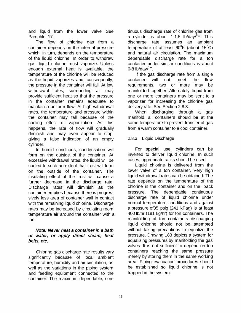
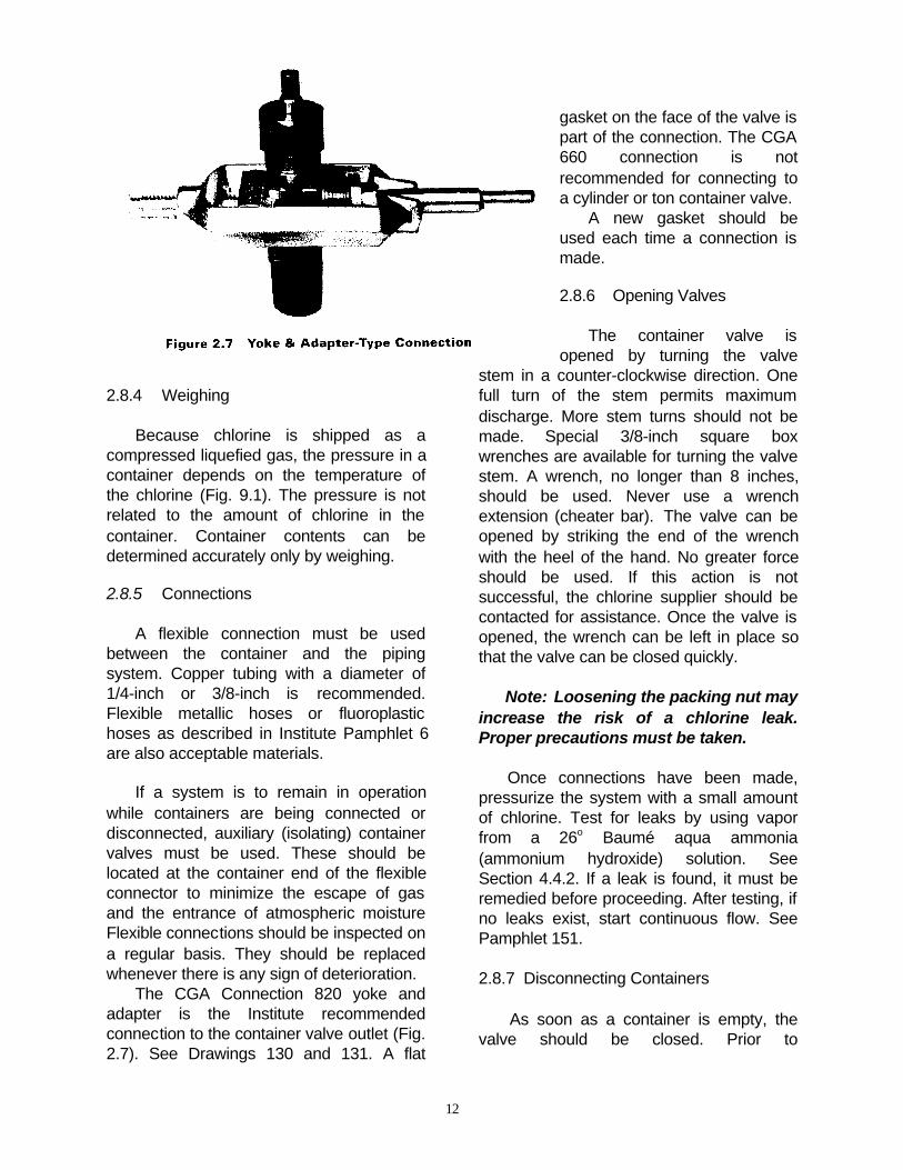
The CGA Connection 820 yoke andadapter is the Institute recommendedconnection to the container valve outlet (Fig.2.7). See Drawings 130 and 131. A flat
gasket on the face of the valve ispart of the connection. The CGA660 connection is notrecommended for connecting toa cylinder or ton container valve.
A new gasket should beused each time a connection ismade.
2.8.6 Opening Valves
The container valve isopened by turning the valve
stem in a counter-clockwise direction. Onefull turn of the stem permits maximumdischarge. More stem turns should not bemade. Special 3/8-inch square boxwrenches are available for turning the valvestem. A wrench, no longer than 8 inches,should be used. Never use a wrenchextension (cheater bar). The valve can beopened by striking the end of the wrenchwith the heel of the hand. No greater forceshould be used. If this action is notsuccessful, the chlorine supplier should becontacted for assistance. Once the valve isopened, the wrench can be left in place sothat the valve can be closed quickly.
Note: Loosening the packing nut mayincrease the risk of a chlorine leak.Proper precautions must be taken.
Once connections have been made,pressurize the system with a small amountof chlorine. Test for leaks by using vaporfrom a 26o Baumé aqua ammonia(ammonium hydroxide) solution. SeeSection 4.4.2. If a leak is found, it must beremedied before proceeding. After testing, ifno leaks exist, start continuous flow. SeePamphlet 151.
2.8.7 Disconnecting Containers
As soon as a container is empty, thevalve should be closed. Prior to

13
disconnecting, a means of removing thechlorine trapped in the flexible connectingline should be provided. This can beaccomplished by either purging the line withdry air or nitrogen with a dew point of -400F(-400C) or lower or by applying a vacuum.The container should be cautiouslydisconnected in case residual chlorineremains in the lines. The outlet cap shouldbe applied promptly and the valve protectivehousing should be replaced. The open endof the disconnected flexible line should becapped promptly to keep atmosphericmoisture from entering the system.

14
3.1 General
Bulk chlorine is shipped in tank cars,tank motor vehicles, portable tanks andbarge tanks. Most common chlorineshipments are made in single-unit tank carsof 55 or 90 ton capacity. Chlorine may alsobe transferred in bulk by pipeline which isdiscussed in Pamphlet 60.
3.2 Tank Cars
3.2.1 General
The following is generalized informationon chlorine tank cars. For more detailedinformation, see Pamphlet 66.
3.2.2 Specifications
The most commonly used tank cars(Fig. 3.1) have a chlorine capacity of 55 or90 tons. However, 16, 30, and 85 ton carsare authorized and are in use. Byregulation, tank cars may not be loaded
with chlorine in excess of these nominalweights.
Chlorine tank cars must comply with 49CFR 179.102-2. Similar text appears in TCRegulations at 79.102-2. An exception forolder cars appears in 49 CFR 173.314(c)note 12 and TC regulation 73.314(c) note12.
The regulations require tank cars to beequipped with a pressure relief devicewhose setting is stenciled on the side of thecar. Tank cars equipped with manual anglevalves must have interior eduction pipesused for liquid discharge equipped withexcess flow valves of approved design.Tank cars equipped with pneumaticallyoperated valves (POVs) should be equippedwith a ball-check valve on all four valveopenings.
Tank cars must be insulated with fourinches of insulating material. The insulationreduces the increase in vapor pressureduring hot weather and helps maintainpressure needed to unload the car duringcold weather. The current standard is two
3 BULK SHIPPING CONTAINERS
15
inches of glass fiber placed over two inchesof ceramic fiber. Older cars are equippedwith four inches of cork or urethane foam.
3.2.3 Manway Arrangement
3.2.3.1 General
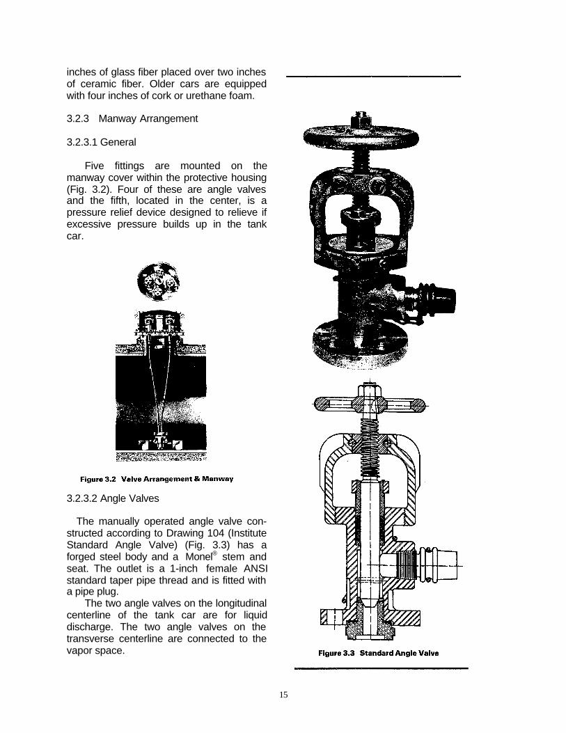
Five fittings are mounted on themanway cover within the protective housing(Fig. 3.2). Four of these are angle valvesand the fifth, located in the center, is apressure relief device designed to relieve ifexcessive pressure builds up in the tankcar.
3.2.3.2 Angle Valves
The manually operated angle valve con-structed according to Drawing 104 (InstituteStandard Angle Valve) (Fig. 3.3) has aforged steel body and a Monel® stem andseat. The outlet is a 1-inch female ANSIstandard taper pipe thread and is fitted witha pipe plug.
The two angle valves on the longitudinalcenterline of the tank car are for liquiddischarge. The two angle valves on thetransverse centerline are connected to thevapor space.

16
Equivalent manual angle valves fromvarious valve producers and approved bythe Association of American Railroads TankCar Committee may also be used. Theexterior appearance of these valves issimilar to the Institute standard angle valve,but may have different design features, e.g.,replacement outlet port, bellows-seals, stempacking arrangements.
Chlorine tank cars may also beequipped with pneumatically operatedvalves (POVs). The manway cover for tankcars equipped with POVs is different. ThePOV is a dual valve system consisting of anexternal bellows seal, angle globe valve,and a spring loaded ball check valve with atop-mounted pneumatic actuator, includingprovisions for a manual override. Actuatingthe valve simultaneously operates thespring loaded check valve mounted beneaththe angle globe valve. The valves aredesigned to be opened or closedpneumatically and are of a fail-safe/fail-closed design with a loss of pneumaticpressure. The valve also may be openedmanually with a specially designed devicethat mounts on top of the angle globe valve.The device may be attached to a cord
allowing thevalve to be
trippedsafe/closed.
See Pamphlet93.
3.2.3.3 ExcessFlow Valves
Except fortank carsequipped withpneumatically
operatedvalves, undereach liquidvalve there isan excess-
flow valve (Fig. 3.4). The excess-flow valveconsists of a rising ball which closes whenthe rate of flow exceeds a predeterminedvalue. It does not respond to pressure in thecar. It is designed to close automatically
against the flow of liquid chlorine if the anglevalve is broken off in transit. It may close if acatastrophic leak involving a brokenconnection occurs but it is not designed toact as an emergency shut-off device duringtransfer. The excess-flow valves have amaximum operating flow rate of 7,000 lb/hr(3,200 kg/hr), 11,000 lb/hr (5,000 kg/hr) or15,000 lb/hr (6,800 kg/hr). Tank cars equip-ped with POVs are equipped with a ballcheck valve under both the liquid and vaporoutlets.
3.2.3.4 Eduction Pipes
Liquid chlorine is withdrawn through 1¼-
inch eduction pipes (Fig. 3.2). (Bottomoutlets are not permitted in chlorine cars.)The eduction pipes are attached to theexcess-flow valves, or directly to the bottomof the tank car dome if equipped with POVs,and extend to the bottom of the car. One orboth eduction pipes may be used to unloadthe car.
3.2.3.5 Pressure Relief Device
In the center of the manway cover is aspring loaded pressure relief device (Fig.3.5). The device is set to start-to-discharge

17
at a gage pressure of 225 psig (1551 kPag)on cars stenciled 105J300W or 105S300Wor at a gage pressure of 375 psig (2586kPag) on cars stenciled 105J500W or105S500W.
3.2.4 Transfer Operations
The following is general information. Formore detailed information, refer to Pamphlet66.
3.2.4.1Precautions
• Every site handling chlorine shouldhave an on-going safety program. Specialattention should be directed to theappropriateness of emergency proceduresand to equipment to be used in anemergency.
• All personnel responsible for transferoperations should be knowledgeable aboutthe facility’s emergency response plan forhandling spills and leaks of products.• DOT, OSHA and IC have specifictraining requirements applicable to handlingof hazardous materials. Chlorine transferoperations must be performed only bypersonnel who are trained as required byapplicable hazardous material regulations.
• Chlorine tank cars must be loaded orunloaded on a private track or siding.
• Chlorine transfer operations shouldincorporate an emergency shut-off systemto reduce the possibility of a major release.See Pamphlet 57.
• It is recommended that chlorine tankcars be loaded on a track scale.
• The transfer operation area should beadequately illuminated during transferoperations.
• During all times when the tank car(s) isconnected for transfer of product:
- Tank car brakes must be set andwheels chocked.
- Caution signs (blue flags or lights) mustbe so placed on the track to give necessarywarning to persons approaching the tankcars from the open end(s) of the siding.- Derail devices should be placed at theopen end(s) of the siding not less than
approxlmately one car length from the car(s)being transferred, unless the tank car(s) isprotected by a closed and locked switch.
• Before the transfer valves are opened,the loading/unloading connections must beattached securely to the tank carconnections. All connections should beleak-checked. See Section 4.4.2.• The transfer area should be checked tomake sure all safety equipment (e.g., self-contained breathing apparatus, emergencykits, eye wash fountains) is in its properplace and operable.
• A suitable operating platform should beprovided at the transfer station for easyaccess to the protective housing, forconnection of lines, for the operation ofvalves and for rapid escape, if required. SeePamphlet 66.
3.2.4.2 Connections
Transfer operations should be donethrough a suitable flexible connector topermit the movement of the tank car on itssprings. Recommended specifications forchlorine transfer hose as well as moredetailed information pertaining to piping andother components are contained inPamphlet 6.
Nipples for insertion into the tank carangle valve should have clean, sharpthreads. A non-reactive lubricating pipedope or PTFE tape should be used toprevent galling of the threads. It should beapplied in such a manner as to prevent itsentry into the piping. After the connectionsare tight, add a small amount of chlorine tothe system by slightly opening the liquidangle valve for a second or two topressurize the piping with chlorine gas andtest for leaks. See Section 4.4.2.
During unloading, if the liquid anglevalve is opened too rapidly or an unusuallyhigh flow rate is established, the excess-flow valve will close. If this situation occurs,the angle valve should be closed until themetal ball in the excess-flow valve dropsback into place. A click will be heard whenthe ball drops.
18
If this action is unsuccessful, themanway cover next to the valve may betapped sharply with a hammer.
Note: The valve must never bedirectly struck.
If the ball in the excess flow valve is stillnot dislodged, nitrogen from a cylinder, orsome other non-reactive gas, may beapplied to the down-stream side of theexcess flow valve. Do not exceed thedesign pressure of the piping system. Liquidangle valve(s) must never be used toregulate the flow rate of chlorine. Thesevalves, if opened, should be kept completelyopen.
3.2.4.3 Pressure Padding
Liquid chlorine usually is unloaded bytank car pressure. See Pamphlet 66. Thevapor pressure of the chlorine is frequentlyaugmented by a “pad” of dry air or non-reactive gas. It is essential that the air usedfor padding be free from oil and foreignmatter and be dried to a dew point -400F (-400C) or below.
Air for padding should be supplied by aseparate air compressor which is not usedfor any other purpose. To minimize thepotential of a chlorine-hydrocarbon oilreaction, either a non-lubricated compressoror a compressor lubricated with a non-reactive synthetic oil, should be utilized.Filters ahead of the dryers are required toensure oil free dry air if a lubricatedcompressor is used.
The air pad system should be designedto prevent the backflow of chlorine vaporsfrom the car. Lack of a positive backflowprotection with a hydrocarbon lubricatedcompressor may result in a violent reactionof chlorine and oil. A check valve aloneshould not be considered adequate toprevent back flow. See Pamphlet #6.
3.2.4.4 Monitoring
Current DOT and TC regulations requirethat throughout the entire period the tank
car is connected, the car must be attendedby the operator. There may be exceptions tothis general rule. It is the responsibility ofeach transfer site to ensure all applicableregulations are followed. See Pamphlet 66.
3.2.4.5 Disconnecting
A noticeable drop in tank car pressureusually indicates that the tank car is empty.It is desirable to discharge as much of theresidual chlorine as possible to the process.Chlorine lines should be purged with dry airor nonreactive gas to an absorption systemor vented to a vacuum system beforedisconnecting.
After the transfer lines have beendisconnected, the valve outlet plugs shouldbe installed immediately. This is essential toprevent corrosion of the threads byatmospheric moisture. After checking forleaks the protective housing cover must beclosed. After unloading, the DOT placardsmust indicate the car last containedchlorine. The open end of the chlorinetransfer lines should also be protected fromatmospheric moisture with suitable closures.
3.3 Tank Motor Vehicles
3.3.1 General
The following is generalized informationon chlorine tank motor vehicles. For moredetailed information, see Pamphlet 49. InNorth America they usually have a capacityranging from 15 to 22 tons (13,600 kg to20,000 kg) with certain exceptions (Fig.3.6). DOT specifications apply only to thetank; such “cargo tanks” comply withspecification MC331 including the specialrequirements for chlorine, but tanks built tospecification MC330 maybe continued inservice.
3.3.2 Manway Arrangement
3.3.2.1General
The manway arrangement is the sameas that on chlorine tank cars (see Section
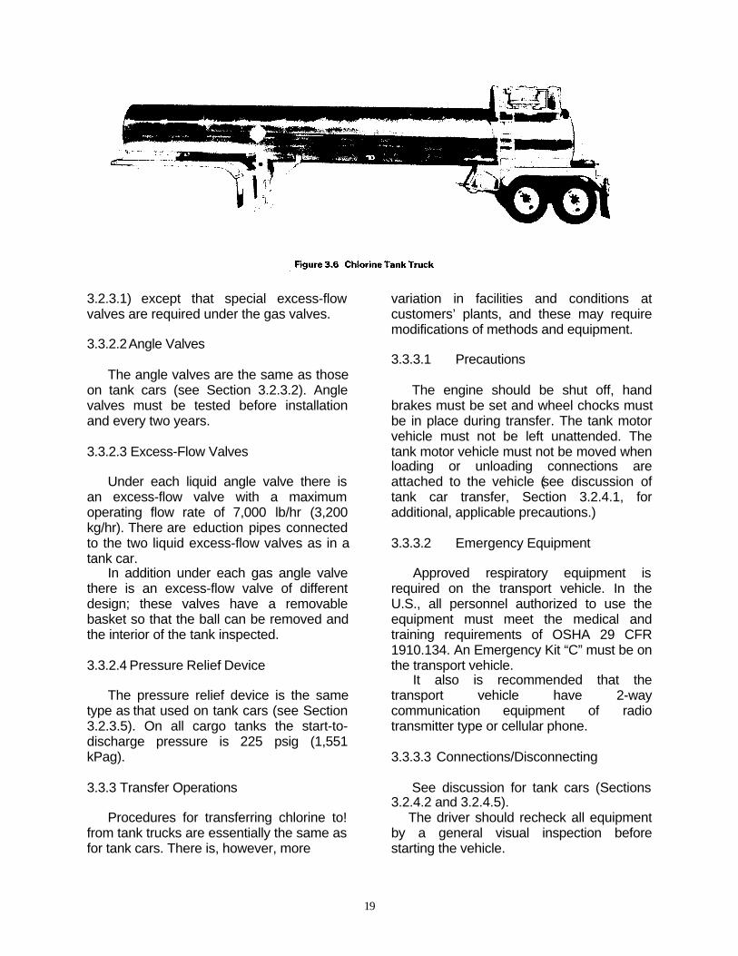
19
3.2.3.1) except that special excess-flowvalves are required under the gas valves.
3.3.2.2Angle Valves
The angle valves are the same as thoseon tank cars (see Section 3.2.3.2). Anglevalves must be tested before installationand every two years.
3.3.2.3 Excess-Flow Valves
Under each liquid angle valve there isan excess-flow valve with a maximumoperating flow rate of 7,000 lb/hr (3,200kg/hr). There are eduction pipes connectedto the two liquid excess-flow valves as in atank car.
In addition under each gas angle valvethere is an excess-flow valve of differentdesign; these valves have a removablebasket so that the ball can be removed andthe interior of the tank inspected.
3.3.2.4 Pressure Relief Device
The pressure relief device is the sametype as that used on tank cars (see Section3.2.3.5). On all cargo tanks the start-to-discharge pressure is 225 psig (1,551kPag).
3.3.3 Transfer Operations
Procedures for transferring chlorine to!from tank trucks are essentially the same asfor tank cars. There is, however, more
variation in facilities and conditions atcustomers’ plants, and these may requiremodifications of methods and equipment.
3.3.3.1 Precautions
The engine should be shut off, handbrakes must be set and wheel chocks mustbe in place during transfer. The tank motorvehicle must not be left unattended. Thetank motor vehicle must not be moved whenloading or unloading connections areattached to the vehicle (see discussion oftank car transfer, Section 3.2.4.1, foradditional, applicable precautions.)
3.3.3.2 Emergency Equipment
Approved respiratory equipment isrequired on the transport vehicle. In theU.S., all personnel authorized to use theequipment must meet the medical andtraining requirements of OSHA 29 CFR1910.134. An Emergency Kit “C” must be onthe transport vehicle.
It also is recommended that thetransport vehicle have 2-waycommunication equipment of radiotransmitter type or cellular phone.
3.3.3.3 Connections/Disconnecting
See discussion for tank cars (Sections3.2.4.2 and 3.2.4.5).
The driver should recheck all equipmentby a general visual inspection beforestarting the vehicle.
20
3.3.3.4 Pressure Padding
See discussion for tank cars (Section3.2.4.3).
3.4 Portable Tanks
Tanks suitable for multi-modaltransportation (road, rail and water) ofchlorine should be built under the provisionsof DOT 51 and special provisions forchlorine. See Pamphlet 49.
3.5 Tank Barges
3.5.1 General
The following is generalized informationon chlorine tank barges. For more detailedinformation, see Pamphlet 79.
Chlorine barge design is dependentupon its geographical operating pattern— inland river or ocean service. The inlandriver units are designed solely for chlorinetransportation with either 4 or 6independent, cylindrical uninsulated pres-sure tanks mounted longitudinally.
The ocean units are multi-product de-signed vessels with chlorine in cylindricalpressure deck tanks and sodium hydroxide,sodium chlorate, and/or sodium hypochloritein center and wing tanks. Both barge typesare subject to U.S. Coast Guard andCanadian Coast Guard regulations.
3.5.2.1 General
Chlorine barge tanks may have one ormore flanged openings on the top of thecargo tanks. No openings are allowed belowthe top surface. The arrangement of valvingis not standardized. Depending on the tankcargo capacities, each tank has either twoor three pressure relief devices and avarying number of angle valves located onthe top manway openings.
3.5.2.2 Angle Valves
Inland chlorine barge cargo tanks are
normally equipped with 4 one-inch ChlorineInstitute Standard Valves utilized for the padgas and liquid discharge control. The oceanservice barge cargo tanks are equipped witha similar number of two-inch valves.
3.5.2.3 Excess-Flow Valves
Each liquid discharge tank assemblyconnection contains an excess flow valvewhich incorporates a ball check that willclose when the discharge flow rate exceedsa predetermined quantity. The gas tankconnection also contains an excess flowvalve. The gas flow valve may contain aremovable basket which allows inspectionof the cargo tank prior to loading. Excessflow valves are designed to close if acatastrophic leak occurs. However, they arenot designed to serve as an emergencyshut-off device during transfer.
3.5.2.4 Eduction Pipes
Liquid chlorine is withdrawn througheduction pipes. The eduction pipes areattached to the excess-flow valves andextend to the bottom of the tank. One orboth eduction pipes maybe used to unloadthe tank.
3.5.2.5 Pressure Relief Devices
Depending on capacity, each barge tankhas two or three pressure relief devices.These are designated 4 JQ and aredesigned to start-to-discharge pressure of300 psig (2,070 kPa). See Pamphlet 41.
3.5.3 Transfer Operations
The following is general information. Formore detailed information, see Pamphlet 79.
3.5.3.1 General
Loading and unloading of chlorinebarges are subject to U.S. and CanadianCoast Guard regulations. Chlorine transfersbetween a vessel and a marine terminalmust be supervised by individuals who have

21
been designated as the Person in Charge.Procedures for withdrawing chlorine frombarges are essentially the same as for tankcars except that diagonal barge cargo tanksmust be discharged together to prevent thebarge from becoming unstable. Variation infacilities and conditions at customers’ plantsmay require modifications of methods andequipment and should be considered beforedischarge is initiated.
3.5.3.2 Personnel Protection
See Section 5-Employee Training andSafety

22
4.1 General
A chlorine emergency may occur duringmanufacture, use or transportation. Trainedemployees, along with a comprehensive,written emergency response plan (Pamphlet64), are necessary to mitigate theconsequences of the emergency. Federal,state and provincial regulations, as well asvarious local fire and building codes,regulate chemical emergency preparednessand response. All persons handling, orresponsible for the handling of chlorine,must be familiar with the contents of thosevaried requirements.
Regulatory requirements deal generallywith preparation and response to chemicaland other emergencies. This section isdesigned to provide additional informationfor use in chlorine emergencies. Help is alsoavailable from CHLOREP (see Sections4.5.1 to 4.5.3) through CHEMTREC in theU.S. and through CANUTEC in Canada.
4.2 Response to a Chlorine Release
As soon as there is any indication of achlorine release, immediate steps must betaken to correct the condition.
Chlorine leaks always get worse if theyare not promptly corrected. When a chlorineleak occurs, authorized, trained personnelequipped with respiratory and appropriateother personal protective equipment (PPE)should investigate and take proper action.Personnel should not enter intoatmospheres containing concentrations ofchlorine in excess of the ImmediatelyDangerous to Life and Health Concentration(10 ppm) without appropriate personalprotective equipment and back-uppersonnel.
Pamphlet 65 provides PPErecommendations for responders to achlorine release. Keep unnecessarypersonnel away and isolate the hazardarea. Persons potentially affected by a
chlorine release should be evacuated orsheltered in place as circumstanceswarrant.
Area chlorine monitors and winddirection indicators can supply timelyinformation (e.g., escape routes) to helpdetermine whether personnel are to beevacuated or sheltered in place.
When evacuation is utilized, potentiallyexposed persons should move to a pointupwind of the leak. Because chlorine isheavier than air, higher elevations arepreferable. To escape in the shortest time,persons already in a contaminated areashould move crosswind.
When inside a building and sheltering inplace is selected, shelter by closing allwindows, doors and other openings, andturning off air conditioners and air intakesystems. Personnel should move to the sideof the building furthest from the release.
Care must be taken not to positionpersonnel without an escape route. A safeposition may be made hazardous by achange in wind direction. New leaks mayoccur or the existing leak may get larger.
If notification of local authorities isrequired, the following information should beprovided:• Company name, address, telephone
number and the name of the person(s)to contact for further information
• Description of the emergency• Travel directions to the site• Type and size of container involved• Corrective measure being applied• Other pertinent information, i.e., weather
conditions, injuries, etc.
4.3 Response to a Fire
If fire is present or imminent, chlorinecontainers and equipment should be movedaway from the fire, if possible. If a non-leaking container or equipment cannot bemoved, it should be kept cool by applyingwater on it.
4 EMERGENCY MEASURES

23
Water should not be used directly on achlorine leak. Chlorine and water reactforming acids and the leak quickly will getworse. However, where several containersare involved and some are leaking, it maybe prudent to use a water spray to helpprevent over-pressurization of the non-leaking containers. Whenever containershave been exposed to flames, cooling watershould be applied until well after the fire isout and the containers are cooled.Containers exposed to fire should beisolated and the supplier should becontacted as soon as possible.
4.4 Releases
4.4.1 General
Chlorine facilities should be designedand operated so that the risk ofa chlorinerelease into the environment is minimized.However, accidental releases and leaks ofchlorine may occur. The overall effects ofsuch releases must be considered.
4.4.2 Detection of Minor Releases andLeaks
A plastic squeeze bottle containing260Baumé aqua ammonia can be used todetect a minor release or leak. If ammoniavapor is directed at a leak, a white cloud willform indicating the source of the leak. If awash bottle is used, the dip tube should becut off so that squeezing the bottle directsvapor, not liquid, out of the nozzle. Avoidcontact of aqua ammonia with brass orcopper. Portable electronic chlorinemonitors can also be used to detect leaks. Ifa leak occurs in equipment or piping, thechlorine supply should be shut off, thepressure relieved and necessary repairsmade.
Leaks around shipping container valvestems usually can be stopped by tighteningthe packing gland. If such tightening doesnot stop the leak, the container valve shouldbe closed. Pamphlets 66 and 151 providefurther details. If simple corrective measuresare not sufficient, the appropriate Chlorine
Institute Emergency Kit should be applied orthe cylinder should be placed in a recoveryvessel designed to contain the leak, and thechlorine supplier notified. See Section 4.8.
4.4.3 Types of Releases
Chlorine releases can be classified aseither instantaneous (puffs) or continuous.See Pamphlet 74.
4.4.3.1 Instantaneous Release
An instantaneous release ischaracterized by the release of chlorine tothe atmosphere in a relatively short periodof time (a few minutes), resulting in a cloudwhich moves across the downwind rangewhile growing in size and decreasing inconcentration. Thus, the concentration ofchlorine monitored at any given pointdownwind will vary overtime depending onthe position of the chlorine cloud.
4.4.3 2 Continuous Release
A continuous release is characterizedby the release of chlorine to the atmosphereover a longer period of time (usually morethan 15 minutes), resulting in a continuousplume which reaches an equilibrium sizeand concentration gradient. Thus, theconcentration of chlorine monitored at anygiven point downwind from the source willbe constant over time for the duration of therelease. The failure of a valve or fitting on alarge container is an example of acontinuous release.
4.4.4 Area Affected
The area affected by a chlorine releaseand the duration of the exposure dependupon the total quantity released, the rate ofrelease, the height of the release point andweather conditions, as well as the physicalform of the chlorine being released. Thesefactors are difficult to evaluate in anemergency situation. Chlorine downwindcan vary from barely detectable to highconcentrations. Pamphlet 74 provides

24
information on the area affected by specificchlorine release scenarios.
4.4.5 Physical Form of the ChlorineReleased
Chlorine occurs as a gas or a liquiddepending on the pressure andtemperature. Typically, chlorine is storedand transported as a liquid under pressure.Whether the release source is a liquid orgas significantly affects the downwinddispersion since liquid chlorine expands involume by nearly 460 times when itvaporizes.
During a release, chlorine can escapeas a gas, a liquid, or both. Whenpressurized liquid or gas is released from acontainer, the temperature and pressureinside the container will decrease thusreducing the release rate.
Escaping liquid may collect in a pooland may actually form a running stream.Chlorine will immediately cool to its boilingpoint (-290F, -340C) as it enters theatmosphere. Upon contact with any heatsource — the air, the ground, or water— theheat will cause the chlorine to boil readily.Typically, the boiling-off rate will berelatively high initially and then decline asthe heat source surrounding the chlorine iscooled.
Since water in bulk provides a vast heatsource for evaporating liquid chlorine, anyliquid falling into water should be assumedto vaporize. For this reason, water shouldbe prevented from coming in contact with aliquid chlorine pool, and chlorine should beprevented from flowing into water drains.
4.4.6 Effect of Chlorine on theEnvironment
4.4.6.1 Vegetation
Chlorine causes bleached spots onleafy plants due to attack on chlorophyll inleaves. Mature leaves are most susceptibleto chlorine injury. Usually the plant itself isnot destroyed although yield or growth ratemay be retarded.
4.4.6.2 Animals
The U.S. National Institute for Occupa-tional Safety and Health 1980 “Registry ofToxic Effects of Chemical Substances” liststhe following inhalation LC50s (concentrationof chlorine in air lethal to 50% of the testpopulation of the defined animal, exposedover the specified time period):
Human 840ppm/30 minutesRat 293ppm/60 minutesMouse 137ppm/60 minutes
The lowest concentration of chlorine inair (other than LC50) which has beenreported to cause death in humans oranimals is listed as 500ppm/5 minutes.
4.4.6.3 Aquatic Life
Chlorine is only slightly soluble in waterand there would be little absorption from acloud of chlorine gas. Many forms of aquaticlife are adversely affected by chlorine inconcentrations well below 0.1 ppm. Chlorineis listed as a marine pollutant by DOT.
4.5 Transportation Emergencies
DOT and TC require that any personwho offers chlorine for transportation mustprovide a staffed 24-hour emergencyresponse telephone number that can becalled in the event of an emergencyinvolving chlorine. For emergenciesinvolving the transportation of chlorine, theChlorine Institute’s CHLOREP, the ChlorineEmergency Plan, can provide assistance.
4.5.1 CHLOREP
The Chlorine Emergency Plan(CHLOREP) was established in January1973 by the Institute as an industry-wideprogram to improve the speed andeffectiveness of response to chlorineemergencies in the United States andCanada.
The primary purpose of the formalizedplan is to minimize the risk of injury arisingfrom the actual or potential release of

25
chlorine during emergencies occurring inthe course of transportation, at distributionpoints, or at chlorine user locations. Underthis plan, the United States and Canadahave been divided into regional sectorswhere trained emergency teams fromproducing, packaging, distribution andconsuming plants are on constant alert on a24-hour basis to handle possible or actualchlorine releases.
During a chlorine emergency, anycarrier, customer, or civil authority canobtain basic emergency information and beput in contact with the closest chlorineemergency group through eitherCHEMTREC (U.S.) or CANUTEC (Canada).CHEMTREC and CANUTEC can becontacted as indicated in the next section.
4.52 CHEMTREC, CANUTEC, & CECOM
In the United States, the ChemicalTransportation Emergency Center(CHEMTREC), in Arlington, VA is thedispatch agency which is utilized.CHEMTREC operates around the clock, 24hours a day, 7 days per week, to receivedirect dial toll free calls from any point in thecontinental United States at 1-800-424-9300. The number for Alaska and Hawaiiand for calls from marine radio telephonesis 703-527-3887.
CHEMTREC provides immediate advicefor those at the scene of emergencies, thenpromptly contacts the appropriate respondergroup as required. ln many cases, this willbe the shipper. However, in some cases thedesignated response group is called andthen the shipper is notified.
In Canada, the Canadian TransportEmergency Center (CANUTEC) in Ottawa,is the dispatch agency. Its telephonenumber is 613-996-6666. It may be calledcollect. CANUTEC, administered byTransport Canada, operates similarly toCHEMTREC.
In Mexico, Centro de Comunicacionesde la Direccion General de Protecion Civil(CECOM) is the dispatch agency andoperates similarly to CHEMTREC andCANUTEC. Its telephone number is 91-800-
70-226. For calls originating in Mexico Cityand the metropolitan area, the telephonenumber is 7-04-11-69 or 7-05-31-48.
If a chlorine leak develops in transitthrough a populated area, appropriateemergency measures should be taken asquickly as possible. If a vehicle transportingchlorine cylinders or ton containers isdisabled and there is any possibility of fire,the containers should be removed from thevehicle.
If a tank car or cargo tank trailer isdisabled and chlorine is leaking, appropriateemergency procedures should be institutedin consultation with local authorities.Clearing of track or highway should not bestarted until safe working conditions areestablished. See Section 4.3 for action totake if a fire occurs.
These additional specific actions maybe taken to contain or reduce leaks:
• If a container is leaking chlorine, turn it,if possible, so that gas instead of liquidescapes. The quantity of chlorine thatescapes from a gas leak is much less thanthe amount that escapes from a liquid leakthrough the same size hole.
• If practical, reduce pressure in thecontainer by removing the chlorine as gas(not as liquid) to process or a disposalsystem as described below.
• It may be desirable to move thecontainer to an isolated spot where theconsequences will be mitigated.
• Apply the appropriate Chlorine InstituteEmergency Kit or place the cylinder in arecovery vessel designed to contain theleak (see Section 4.8).
A leaking chlorine container must notbe immersed or thrown into a body of water;the leak will be aggravated and thecontainer may float when still partially full ofliquid chlorine allowing gas evolution at thesurface.
Regulations prohibit the normalshipment of a leaking chlorine container or acontainer which has been exposed to fire,whether full or partially full. It may henecessary in some instances to ship adefective chlorine container. In such casesspecial arrangements are required and the

26
chlorine supplier should be consulted first.
4.6 Disposal of Chlorine
If a leak occurs at a consuminglocation, it may be best to dispose of thechlorine through the regular consumingprocess or to run a temporary line to theconsuming point. If the consuming processcannot handle chlorine under emergencyconditions, a standby alkali absorptionsystem should be considered. It must berecognized that systems consuming liquidchlorine at low rates will not significantlyreduce pressure in the supply container.
In order to reduce pressure in thesupply container, chlorine must be removedas a gas at a rate high enough to causecooling of the remaining liquid. See Section2.8.2.
4.7 Absorption Systems
A simple absorption system consists ofa suitable tank capable of holding therequired alkaline solution. The alkali shouldbe stored in a form such that a solution canreadily be prepared when needed. After thesolution is prepared, the chlorine can bepassed from the container into the solutionthrough a connection weightedto hold the outlet of the transfer hose or pipebeneath the level of the solution. Do notimmerse the container. See Tables 4.1Aand 4.1B for recommended solution (therecommended alkali quantities provide 20%excess).
Note: When absorbing chlorine inalkaline solutions, the heat of reaction issubstantial. Caustic solutions can causeburns to personnel.
The process should be monitored toensure the absorption is controlled as toheat and reaction. Do not boil the solution orexceed the capacity of the reaction.
4.8 Emergency Kits and RecoveryVessels
Chlorine Institute Emergency Kits andcylinder recovery vessels are designed tocontain most leaks
which may be encountered in chlorineshipping containers. The following kits andrecovery vessels (Figure 4i1) are available.
m Kit A - for 100 lb and 150 lb cylindersm Kit B - for ton containers.m Kit C - for tank cars and tank trucks.m Recovery vessels for cylinders.
These kits operate on the principle ofcontaining valve leaks by applying hoodsand gaskets. For cylinders and toncontainers, patches are provided for sealingoff a small hole in the side wall. Cappingdevices are provided for fusible plugs in toncontainers.
The kits contain step-by-stepinstructions for the use of the devices. Thenecessary tools are included, but personalprotective equipment is not included.Pamphlets lB/A, IB/B, and lB/C provide
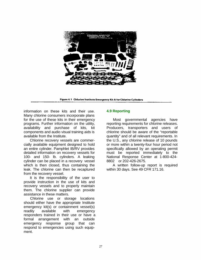
27
information on these kits and their use.Many chlorine consumers incorporate plansfor the use of these kits in their emergencyprograms. Further information on the utility,availability and purchase of kits, kitcomponents and audio visual training aids isavailable from the Institute.
Chlorine recovery vessels are commer-cially available equipment designed to holdan entire cylinder. Pamphlet IB/RV providesdetailed information on recovery vessels for100- and 150- lb. cylinders. A leakingcylinder can be placed in a recovery vesselwhich is then closed, thus containing theleak. The chlorine can then be recapturedfrom the recovery vessel.
It is the responsibility of the user toprovide instruction in the use of kits andrecovery vessels and to properly maintainthem. The chlorine supplier can provideassistance in these matters.
Chlorine use or storage locationsshould either have the appropriate Instituteemergency kit(s) or containment vessel(s)readily available with emergencyresponders trained in their use or have aformal arrangement with an outsideemergency response group that canrespond to emergencies using such equip-ment.
4.9 Reporting
Most governmental agencies havereporting requirements for chlorine releases.Producers, transporters and users ofchlorine should be aware of the “reportablequantity” and of all relevant requirements. Inthe U.S., any chlorine release of 10 poundsor more within a twenty-four hour period notspecifically allowed by an operating permitmust be reported immediately to theNational Response Center at 1-800-424-8802 or 202-426-2675.
A written follow-up report is requiredwithin 30 days. See 49 CFR 171.16.

28
5.1 Employee Training
Safety in handling chlorine depends, toa great extent, upon the effectiveness ofemployee training, proper safety instructionsand the use of suitable equipment. It is theresponsibility of the employer to train itsemployees and to document such trainingas appropriate and as required byregulation. It is the responsibility ofemployees to carry out correct operatingprocedures safely and to properly use thesafety equipment provided.
Employee training should include:• Instruction and periodic refresher
courses in operation of chlorineequipment and handling of chlorinecontainers.
• Instruction in the properties and physi-ological effects of chlorine. A MaterialSafety Data Sheet (MSDS) for chlorineis available from chlorine suppliers.
• Instruction to report to the properauthority all equipment failures andchlorine leaks.
• Instruction and periodic drills regarding:- Locations, purpose, and use ofchlorine emergency equipment, firefighting equipment, fire alarms and shut-down equipment such as valves andswitches.- Use of emergency kits, such as theChlorine Institute Emergency Kits A, B,or C and the recovery vessel, if they arepart of emergency equipment andplanning at the location. Training shouldinclude the actual installation of kits oncontainers.- Locations, purpose, and use ofpersonal protective equipment.- Locations, purpose, and use ofsafety showers, eye baths, bubblerfountains or the closest source of waterfor use in emergencies.- Locations, purpose, and use ofspecialized first aid equipment.
5.2 Personal Protective Equipment
5.2.1 Availability and Use
Exposure to chlorine can occurwhenever chlorine is handled or used.Personal protective equipment (PPE) foremergency use should be available awayfrom areas of likely contamination. Ifchlorine is used in widely separatedlocations, personal protective equipmentshould be available near each use point.Pamphlet 65 provides recommendations forspecific tasks including loading! unloading,initial line entry, material sampling, andemergency response.
5.2.2 Respiratory Equipment
All personnel entering areas wherechlorine is stored or handled should carry orhave immediately available an escape typerespirator. Respiratory equipment should beselected based on evaluation of hazardsand degree of potential exposure. Forexample, when tank cars, ton containers orcylinders are connected to or disconnectedfrom plant piping, small releases of chlorinecan occur. The need for respiratoryprotection during such operations should bedetermined. See Pamphlets 65 and 75.
Chemical cartridge respirators or fullface canister gas masks offer adequatetemporary protection provided the oxygencontent in the air is greater than 19.5% andthe chlorine concentration does not exceedthe rated capability of the respirator. Theneed to protect the eyes from chlorineshould be part of the evaluation ofappropriate respiratory equipment. Pres-sure-demand self-contained breathing ap-paratus (SCBA), with full face piece, isrequired for performing tasks when chlorinemay be present unless air sampling verifiesthe chlorine concentration is such that alower level of respiratory protection provides
5 EMPLOYEE TRAINING AND SAFETY

29
CONFINED SPACE ENTRY TIPS
• Suitable respiratory and other protective equipment for anyone enteringconfined space;
• Safety harness and life line for all workers in a confined space;• Supervision of the operation from outside the confined space at all
times;• No entry for rescues without appropriate respiratory protection, safety
harness, life line, and back-up personnel;• See OSHA standard 29 CFR 1910.164.
protection.Self-contained breathing apparatuses
should be located on site near the chlorinestorage and use areas readily accessible tothe trained responders. Documented,regularly scheduled training is required toassure competency with self-containedbreathing apparatuses. If arrangementshave been made to use an approvedoutside emergency response group, thenemergency responders and the self-contained breathing apparatuses may belocated off-site.
Fit testing and regular maintenanceprograms for respirator equipment arenecessary.
5.2.3 Other Personal Protective Equipment
Specialized personal protectiveequipment is not required for performingmany routine plant operations. However,plant practice may dictate the need for eyeand head protection as well as long pants,shirts, and safety shoes.
5.3 Confined Space Entry
Confined space entry procedures mustcomply with all applicable local codes andregulations. The OSHA standard 29 CFR1910.146 must be adhered to by mostfacilities in the United States.
Some key points to be considered:• Workers entering the confined space
must be equipped with suitablerespiratory and other protectiveequipment;
• Workers must be equipped with a safetyharness and life line;
• A person must oversee the operationfrom outside thc confined space at alltimes;
• Neither the overseer nor any otherperson should enter the confined spaceto rescue a victim without appropriaterespiratory protection, safety harness,life line, and backup personnel.
5.4 Personal Exposure Monitoring
The characteristic odor of chlorinemakes its presence known atconcentrations well below the permissibleexposure level (PEL). Because the odor ofchlorine in itself is an inadequate indicatorof concentration, it is essential that somequantitative measure of exposure bedetermined. This is necessary to insure thatthe health of workers is not impaired and todetermine compliance with any applicableregulations.
The OSHA PEL is 1 ppm, expressed asa “ceiling” exposure level. The AmericanConference of Governmental IndustrialHygienists (ACGIH) has set the followingthreshold limit values (TLVs): TLV-TWA (8hours) at 0.5 ppm and the TLV-STEL (15minutes) at 1.0 ppm.

30
6.1 Hazards to Health
6.1.1 General
Chlorine gas is primarily a respiratoryirritant. It is so intensely irritating that lowconcentrations in air (well below l ppm) arereadily detectable by most people. At lowconcentrations chlorine gas has an odorsimilar to household bleach. As theconcentrations increase from the level ofdetection by smell so does symptomatologyin the exposed individual. At chlorineconcentrations above 5 ppm the gas is veryirritating and it is unlikely that any personwould remain in such an exposure for morethan a very brief time unless the person istrapped or unconscious. The effects ofexposure to chlorine may become moresevere for up to 36 hours after the incident.Close observation of exposed individualsshould be a part of the medical responseprogram. See Pamphlets 63 and 90 and thevideo “Health Effects from Short-TermChlorine Exposure.”
6.1.2 Acute Toxicity
In concentrations near the threshold ofsmell, chlorine gas will, after several hoursof exposure, cause mild irritation of the eyesand of the mucous membrane of therespiratory tract. As concentrations increasethere is an increase in the irritating effect onthe eyes, coughing mechanism and on theupper and lower respiratory tract witheventual difficulty in breathing. As theduration of exposure and/or theconcentration increase, the affectedindividual may become apprehensive andrestless with coughing accompanied bythroat irritation, sneezing, and excesssalivation. At higher levels there is vomitingassociated with labored breathing. Inextreme cases difficulty in breathing can
progress to the point of death throughsuffocation. An exposed person with pre-existing medical/cardiovascular conditioncan have an exaggerated response.
Liquid chlorine in contact with the eyesor skin will cause local irritation and/orbums. All symptoms and signs resultdirectly or indirectly from its direct irritatingaction. There are no known systemiceffects.
6.1.3 Chronic Toxicity
Most studies indicate no significantconnection between adverse health effectsand chronic exposure to low concentrationsof chlorine. A 1983 Finish study (Reference10.18.14) did show an increase in chroniccoughs and a tendency for hypersecretionof mucous among workers. However, theseworkers showed no abnormal pulmonaryfunction in tests or chest x-rays.
In December 1993, the Chemical Indus-try Institute of Toxicology issued its reporton a study on the chronic inhalation ofchlorine in rats and mice (Reference10.17.1). Rats and mice were exposed tochlorine gas at 0.4, 1.0 or 2.5 ppm for up to6 hours a day and 3-5 days/week for up to 2years. There was no evidence of cancer.Exposure to chlorine at all levels producednasal lesions. Because rodents areobligatory nasal breathers, how theseresults should be interpreted for humans isnot clear.
6.2 Preventive Health Measures
6.2.1 Physical Examinations
The Institute recommends that chlor-alkali producers provide baseline andperiodic medical examinations foremployees potentially exposed to chlorine.The examination should consist of acomplete medical history and physical
6 MEDICAL ASPECTS AND FIRST AID

31
examination, including chest x-ray (14 inchx 17 inch) and baseline respiratory functionstudies (FVC, FEVI). Specific reference torespiratory allergies, congenital or acquiredpulmonary and/or cardiac disease isnecessary. Chronic eye conditions (i.e.chronic conjunctivitis) should beascertained. It should be determined thatthe employee is physically capable ofwearing respiratory protection equipment.See Pamphlet 126.
Chlorine users should adopt a medicalsurveillance program suitable to their needs.
6.3 First Aid
First aid is the immediate temporarytreatment given to an exposed individualbefore the services or recommendations ofa physician are obtained. Prompt action isessential. Firmness and assurance will helpto alleviate anxiety. Medical assistancemust be obtained as soon as possible.Never give anything by mouth to anunconscious or convulsing person.
6.3.1 Inhalation
6.3.1.1 Respiratory Assistance
In all cases, first move the victim to anarea free of chlorine. If breathing hasapparently ceased, the victim should begiven cardiopulmonary resuscitation (CPR)immediately. If breathing has not ceased,the exposed individual should be placed in acomfortable position. In severe cases, thepatient should lie down with the head andtrunk elevated to a 45-60 degree position.Slow, deep breathing should beencouraged. Trained personnel shouldadminister humidified oxygen by inhalationas soon as possible.
6.3.1.2 Oxygen Administration
Oxygen should be administered by firstaid attendants trained in the use of thespecific oxygen equipment. Suitableequipment for the administration of oxygenshould be available either on site or at a
nearby facility. Such equipment should beperiodically tested. More sophisticatedinhalation equipment is available in mostemergency facilities. Humidified oxygenshould be used whenever possible.
6.3.2 Contact With Skin
If liquid chlorine has contaminated theskin or clothing, an emergency showershould be used immediately and contami-nated clothing should be removed under theshower. Flush contaminated skin withcopious amounts of running water for 15minutes or longer. Thermal burns, due tothe cold temperature of liquid chlorine, maybe more damaging than any chemicalreaction of chlorine and the skin. Exposureto gaseous chlorine can irritate the skin. Donot attempt chemical neutralization or applyany salves or ointments to damaged skin.Refer to a physician if irritation persists afterirrigation or if skin is broken or blistered.
6.3.3 Contact With The Eyes
If the eyes have been exposed to anyconcentration of chlorine in excess of thePEL, they should be flushed immediatelywith copious quantities of tepid runningwater or a direct stream of water for at least15 minutes.
Note: Never attempt to neutralizewith chemicals.
The eyelids should be held apart duringthis period to ensure contact of water withall accessible tissue of the eyes and lids.Medical assistance must be obtained assoon as possible. If such assistance is notimmediately available, eye irrigation shouldbe continued for a second 15-minute period.Nothing but water should be applied unlessordered by a qualified health care provider.
6.4 Medical Management of ChlorineExposures
6.4.1 General Principles

32
• All individuals who have developedsymptoms as a result of an acuteoverexposure to chlorine gas by inhalationshould be placed under the supervision ofmedical personnel trained in the treatmentof chlorine exposure.• There is no known specific antidote foracute chlorine exposure. However, promptmedical assessment and supportivemeasures are necessary to obtain goodtherapeutic results.• If individual is unconscious andvomiting, take steps necessary to protectthe airway from obstruction.• Alleviate anxiety by communicating withthe patient the various proceduresundertaken and elicit his/her cooperation,especially in breathing exercises.• Position patient in chair; in severe caseshave the patient lie down with the head andtrunk elevated to a 45-60 degree position.• Encourage slow, regular respiration.• Humidify air.
6.4.2 Therapy for Specific PhysiologicalDisturbances
Note: The following notes regardingtherapy are intended for generalguidance only. Final determination ofspecific medical intervention(s) shouldonly be made by skilled medicalpersonnel upon full consideration ofeach patient’s overall medical condition.Provision of any treatment without fullmedical assessment by competentpersonnel is not recommended.
6.4.2.1 Pulmonary Edema
• Administer 60 to 100% humidifiedoxygen at 6 liters per minute.
• Intermittent use of positive pressurebreathing apparatus may be valuable inreducing edema. Caution is required if thereare coexisting medical conditions (e.g.,peripheral circulatory collapse) which maybe a contraindication to its use.
• Test arterial blood gases for pulmonarystatus.
• Chest X-rays: Baseline and follow-upare indicated (pulmonary edema may not beevidentfor up to 36 hours after exposure).
• Cardiac monitoring should be employed.• A diuretic furosemide (lasix) may be
used.• There is inconclusive evidence regardingthe use of corticosteroids to prevent oralleviate pulmonary edema. The dosageand frequency of administration of anysteroid therapy should only be determinedby a qualified physician in keeping withclinical findings of a medical assessment.
• The use of antibiotics may beconsidered to protect against secondarypulmonary infection.
6.4.2.2 Bronchospasm
Systemic bronchodilators administeredeither by subcutaneous injection,intravenously or nebulized into theinspiratory air may be beneficial if patient isconscious and when spasm is present.
6.4.2.3 Increased Mucus Secretion
Positive pressure treatment andnebulized detergents may be beneficial.Care should be taken to maintain thepatient’s hydration and to humidify theinspired air.
6.4.2.4 Excitement Phenomenon
• This occurs as a result of centralstimulation and emotional disturbances.
• Reassurance is best accomplishedwithout the use of sedatives. • Use of sedatives should only beconsidered by qualified medical personnelfollowing medical assessment and onlyemployed under close supervision ofrespiratory function to monitor progress.
6.4.3 Delayed Effects
The inhalation of any irritating gas maylead to delayed reactions such aspulmonary edema. Since physical exerciseappears to have some relation with the
33
incidence of delayed reaction, it isrecommended that any patient who has hadsevere inhalation exposure should be keptat rest for a period of observation. Thelength of observation will depend on theclinical assessment of the exposedindividual. Observation may be required upto several days after exposure. Excitement,apprehension and/or emotional distressmay persist after a period of observationfollowing a severe exposure.

34
7.1 Structures
Buildings and structures to housechlorine equipment or containers shouldconform with local building and fire codes,and with this document. Any building usedto house chlorine equipment or containersshould be designed and constructed toprotect all elements of the chlorine systemfrom fire hazards. If flammable materials arestored or used in the same building, then afire wall should be erected to separate thetwo areas. Non-combustible construction isrecommended.
Chlorine monitoring equipment whichcontinuously samples the air and detectsthe presence of chlorine is available andshould be considered in any storage oroperating area where chlorine can bereleased. See Pamphlet 73.
At least two exits should be providedfrom each separate room or building inwhich chlorine is stored, handled or used.Exit doors should not be locked and shouldopen outward. Platforms should bedesigned to facilitate egress and two ormore access stairways or ladders should beconsidered. Steel structures should beprotected to prevent corrosion.
7.2 Ventilation
7.2.1 General
All ventilation systems for buildings thathouse equipment or containers shouldconform with applicable building coderequirements, American Conference of Gov-ernmental Industrial Hygienists (ACGIH)recommendations (Reference 10.4.2) andwith this manual. The building ventilationsystem should provide fresh air for normaloperation and should take into considerationthe possibility of a leak. In some casesnatural ventilation may be adequate; other-wise, mechanical ventilation systems should
be provided.Previously, the Institute has
recommended that the building ventilationallow for a complete change of air with freshair in less than four minutes. The Institutenow believes such a recommendation maynot be compatible with current designphilosophies as follows:
Section 8003.1.8.2 of the 1994Uniform Fire Code (see Section 8.6)requires mechanical ventilation atthe rate of not less than one (1)ft3/minute per square foot for floorarea for storage buildings.
Industrial Ventilation (10.4.2)cautions in Section 7.7 that “Airchanges per hour is a poor basis forventilation criteria where envi-ronmental control of hazards, heat,and/or odors is required ... there islittle relationship between ‘airchanges’ and the required con-taminant control.”
The Institute now recommends thatventilation requirements be determined on asite-specific basis. Safeguards should be inplace to insure that persons do not remainin nor enter buildings where chlorine ispresent due to a leak or equipment failurewithout the appropriate personal protectiveequipment.
7.2.2 Air Openings
Chlorine gas is heavier than air andhas a tendency to collect at floor level. Theexhaust air intake should be located at ornear floor level. An elevated fresh air inletmust be provided and should be located foradequate cross ventilation. Multiple fresh airinlets and fans may be necessary tofacilitate adequate ventilation. Fans, if used,
7 ENGINEERING DESIGN AND MAINTENANCE

35
should be made to start and stop from asafe, remote location.
Alternatively, it maybe desirable topressurize an installation with fresh air andto exhaust the contaminated air throughoutlets at floor level.
7.2.3Heating
Rooms containing chlorinator feedequipment should he maintained at anormal indoor temperature of about 60 -700F (about 15 - 200C) to facilitate gasdischarge rates from the container.
7.3 Material for Processing Equipment
7.3.1 General
Commercial liquid chlorine contains onlyminor amounts of impurities and is dryenough to be handled in carbon steelequipment. In the manufacturing process,certain properties unique to chlorine shouldbe considered when considering thematerials of construction.
7.3.2 Water
Wet chlorine may be safely handledwith a variety of materials which can bechosen to suit the process conditions. Somematerials, such as titanium, are suitable forwet chlorine but not for dry chlorine.Titanium reacts violently with dry chlorine.Reference 10.18.13 indicates that titaniumis a safe material in wet gaseous chlorineprovided the partial pressure of watercomponent is greater than 14 mbar (0.20psi) and the temperature is between 150C(590F) and 700C (1580F).
7.3.3 Temperature
Carbon steel used in the handling ofdry chlorine must be kept within definitetemperature limits. Where processtemperatures are expected to exceed 3000F(1490C), the material used should be moreresistant than carbon steel to hightemperature corrosion by chlorine. Above
3920F (2000C) chlorine rapidly attacks steel.Above 4830F (2510C) the reaction isimmediate as carbon steel flames in thepresence of chlorine. Impurities in thechlorine and/or a high surface area of thesteel may significantly lower the auto-ignition temperature of chlorine and steel.
There is also a possibility of brittlefracturing in certain chlorine processingequipment and storage tanks. Where this isthe case, a type of steel should be used thatcan withstand the lowest temperaturespossible in the process.
7.3.4 Chemicals
Several chemicals are normallyinvolved in the manufacture of chlorine,including sulfuric acid, mercury, certainsalts, oxygen and various products of theirreaction with chlorine. Materials ofconstruction should be selected to guardagainst these corrosive or hazardousmaterials that are present in themanufacturing process.
7.3.5 Alternative Materials
Other than steel, a wide variety ofmaterials may be used in chlorine handling.A number of them, particularly plastics, aresuitable but have pressure and temperaturelimitations that must be considered. Caremust be taken to prevent externalmechanical damage.
7.4 Electrolyzers (Cells)
7.4.1 General
Chlorine can be producedelectrolytically by either membraneelectrolyzers, diaphragm cells, or mercurycells. Reference 10.18.7 provides a detaileddiscussion of the electrolytic methods ofchlorine manufacture.
7.4.2 Membrane Electrolyzers
The membrane electrolyzer is thenewest technology for producing chlorine
36
electrolytically. Sheets of perfluorinatedpolymer ion exchange membrane separatethe anodes and cathodes within theelectrolyzer. Ultra-pure sodium chloridesolution (brine) is fed to the anodecompartments, where chloride ions areoxidize to form chlorine gas. Themembranes are cation selective resulting inpredominantly sodium ions and watermigrating across the membranes to thecathode compartments. Water is reduced toform hydrogen gas and hydroxide ions atthe cathodes. In the cathode compartment,hydroxide ions and sodium ions combine toform sodium hydroxide.
Membrane electrolyzers typicallyproduce 30% to 35% sodium hydroxide,containing less than 50 ppm of sodiumchloride. The sodium hydroxide can beconcentrated further, typically to 50%, in anevaporation system.
7.4.3 DiaphragmCells
Currently in North America, more than75% of chlorine production is fromdiaphragm cell technology. The products ofthis type of cell are chlorine gas, hydrogengas, and cell liquor composed of sodiumhydroxide and sodium chloride solution.
An almost saturated brine solution entersthe diaphragm cell anolyte compartmentand flows through the diaphragm to thecathode section.
Chloride ions are oxidized at the anodeto produce chlorine gas.
Hydrogen gas and hydroxide ions areproduced at the cathode. Sodium ionsmigrate across the diaphragm from theanode compartment to the cathode side toproduce cell liquor containing 10% to 12%sodium hydroxide. Chloride ions alsomigrate across the diaphragm resulting inthe cell liquor also containing about 16%sodium chloride. The cell liquor is typicallyconcentrated to 50% sodium hydroxide byan evaporation process. The salt recoveredin the evaporation process is returned to thebrine systems for reuse.
7.4.4 Mercury Cells
In a mercury cell, the cathode is astream of mercury flowing along the bottomof the electrolyzer The anodes aresuspended parallel to the base of the cell, afew millimeters above the flowing mercury.Brine is fed into one end of the cell box andflows by gravity between the anodes andthe cathode. Chlorine gas is evolved andreleased at the anode.
The sodium ions are deposited along thesurface of the flowing mercury cathode. Thealkali metal dissolves in the mercury,forming a liquid amalgam. The amalgamflows, by gravity, from the electrolyzer to thecarbon-filled decomposer, where deionizedwater is added. The water chemically stripsthe alkali metal from the mercury, producinghydrogen and 50% sodium hydroxide. (Inthe decomposer, the amalgam is the anodeand the graphite packing is the cathode.)The stripped mercury is then pumped backto the cell box, where the electrolysisprocess is repeated.
7.5 Chlorinators
Chlorine gas feeding equipment must becarefully selected. Vacuum operatedequipment offers the safest operation forlow capacities. For higher capacities apressure-vacuum system may be required.Pressure piping and connections should beminimized to decrease the possibility of aleak. Equipment manufacturers canrecommend optimum system design.
7.6 Vaporizers
High capacity chlorine gas feedsystems may need a chlorine vaporizer(evaporator). Vaporizers are usually water-jacketed or steam-heated. Careful attentionmust be given to the design and operationof such systems. See Pamphlet 9.
7.7 SupportEquipment
7.7.1 General
Some key support equipment used inchlorine service are included in this section.
37
Equipment used in chlorine must bedesigned either for dry chlorine or for wetchlorine so that proper materials ofconstruction are selected. Most equipmentused in chlorine service is built to a specificdesign code or regulation. Such codes orregulations include ANSI, API, ASME andTEMA standards and OSHA regulations.
7.7.2 Vessels
Materials of construction for vesselsused in wet chlorine applications includecertain plastic-lined or rubber-lined steel,reinforced polyesters, and titanium. Vesselsused in dry chlorine service are usuallycarbon steel.
The minimum fabrication standard formetal vessels operating at greater than 15psig is that given in the ASME Code(Reference 10.5.1) for pressure vessels.Vessels operating at less than 15 psig haveno ASME code requirements, but should bedesigned according to a manufacturer’sspecification. Vessels in vacuum servicerequire special designs to prevent collapse.
7.7.3 Heat Exchangers
Metallic shell-and-tube heat exchangersshould be designed and fabricated in accor-dance with the TEMA Standard and properASME material classifications and codes.Titanium is usually the choice for ”wetchlorine”, and carbon steel is normally usedfor “dry chlorine.” See Section 7.3.2.
7.7.4 Pumps
Pumps for aqueous solutions containingchlorine are constructed of a wide range ofmaterials such as certain plastic-lined orrubber-lined steel, reinforced polyester, andtitanium. Pumps for dry liquid chlorine arespecial items and a supplier of these pumpsshould be contacted before use.
7.7.5 Compressors
Compressors used in dry chlorineservice include centrifugal, non-lubricated
reciprocating, and liquid-ring sealed (sulfuricacid). Compressors should be built inaccordance with the applicable ASME Codeand supplier specifications proper for theapplication. Aluminum, copper, and copperalloys must be avoided.
Fans are sometimes used to boostpressure or move chlorine gas in vent orscrubber systems. In wet chlorine service,rubber-lined, fiberglass reinforced polyesteror titanium are normally used. In drychlorine service, carbon steel is normallyused.
7.7.6 Scrubbers
While scrubbers are an effective meansof absorbing chlorine, the need for ascrubber should be based on a site specifichazard assessment that considers factorssuch as the quantity of chlorine on site, thelikelihood of a release, and theconsequences of a release. See Pamphlet89.
7.8 Piping Systems for Dry Chlorine
Piping as described in this sectionpertains only to above ground fixed piping.For more detailed information on pipingsystems for dry chlorine, see Pamphlet 6.
7.8.1 Materials
In general, carbon steel piping is recom-mended for handling dry chlorine. Stainlesssteels of the 300 series have usefulproperties for low temperature service butcan fail due to chloride stress corrosioncracking, particularly in the presence ofmoisture at ambient or elevatedtemperatures.
7.8.2 Design and Installation
7.8.2.1 General Design
Piping arrangements should be routed forthe shortest distance practical with respectto flexibility, line expansion and good engi-neering practice. Piping systems should be

38
properly supported, adequately sloped toallow drainage, and low spots should beminimized.
Avoid installing lines next to steamlines, acid lines, etc. that could causecorrosion of the chlorine line. Protectchlorine piping from all risks of excessiveheat or fire.
Sprinklers are not needed for chlorinestorage or use areas that have beenconstructed and maintained per Instituterecommendations. In such situations, nocombustible or flammable materials shouldbe present. If sprinklers are installed, theyshould be used only to suppress fires and/orcool containers threatened by fire.
7.8.2.2 Liquid Expansion
Liquid chlorine has a high coefficient ofthermal expansion. See Figure 9.2. If liquidchlorine is trapped between two valves, anincrease in temperature of the trapped liquidwill result in high pressures potentiallyleading to a rupture of the line. The causesof possible rupture must be considered inthe design of any piping systems. Protectionmay be either a suitably designed, operatedand maintained expansion chamber, apressure relief valve, or a rupture disc.
7.8.2.3 Condensation
Condensation or reliquefaction ofchlorine may occur in chlorine gas lineswhich pass through areas where thetemperature is below the temperature-pressure equilibrium indicated in the vaporpressure curve (Fig. 9.1).
Condensation can usually be preventedby the use of a pressure reducing valve orheat tracing and insulating the line. Anyheat tracing installation should be designedsuch that the surface temperature of thepipe shall not exceed 3000F (l490C) to limitthe possibility of a chlorine - carbon steelreaction.
7.8.2.4 Installation
Joints in chlorine piping may be
flanged, screwed or welded depending onpipe size. Flanged and screwed jointsshould be kept to a minimum. If screwedjoints are used, extreme care should betaken to obtain clean, sharp threads. Athread sealant compatible with chlorineshould be used.
Before cutting or welding on a chlorineline, a determination must be made that thesystem is chlorine free. Dry chlorine cansupport combustion of carbon steel, nickeland other materials.
7.8.3 Preparation of Systems for Use
7.8.3.1 Cleaning
All portions of new piping systems mustbe cleaned before use because chlorine canreact violently with cutting oil, grease, andother foreign materials. Cleaning must notbe done with hydrocarbons or alcohols,since chlorine may react violently with manysolvents. New valves or other equipmentreceived in an oily condition should bedismantled and cleaned before use. SeePamphlet 6.
7.8.3.2 Pressure Testing
New chlorine piping systems should betested according to one of the methodsrecommended in Pamphlet 6. Componentswhich may be damaged during testingshould be removed or blocked off Aftertesting, all moisture-absorbing gaskets andvalve packings should be replaced; it isessential that chlorine systems be dried asdescribed below prior to being placed intoservice.
7.8.3.3 Drying
Chlorine piping systems must alwaysbe dried prior to use. Even if water has notbeen purposely introduced into the systemfrom hydrostatic testing or cleaning, dryingis still required due to the introduction ofmoisture from the atmosphere or othersources during maintenance and newconstruction.

39
Drying can be facilitated as the systemis cleaned by passing steam through thelines from the high end until the lines areheated. While steaming, the condensateand foreign matter is drained out. Thesteam supply then should be disconnectedand all the pockets and low spots in the linedrained. While the line is still warm, dry airor inert gas (e.g., nitrogen) having a dewpoint of -400F (-400C) or below should beblown through the line until the dischargegas is also at a dew point of -400F (-400C)or below.
If steam or dry utility system air are notavailable, particular care must be taken incleaning sections of pipe and otherequipment before assembly, and carefulinspection is necessary as constructionproceeds. The final assembled systemshould be purged with dry cylinder air ornitrogen until the discharge gas is at a dewpoint of -400F (-400C) or below.
7.8.3.4 Leak Testing
After drying, the system should be leak-tested with dry air or nitrogen. A soapsolution should be utilized to test for leaks atpiping joints. Chlorine gas may then beintroduced gradually and the system furthertested for leaks with 200 Baume aquaammonia vapor. Care must be taken thatchlorine has diffused throughout the pipingsystems before testing for leaks. Neverattempt to repair leaks by welding until allchlorine has been purged from the system.When leaks have been repaired, the lineshould be retested.
7.9 Piping Systems for Wet Chlorine
Wet chlorine is very corrosive to all of themore common construction metals. At lowpressures wet chlorine can be handled inchemical stoneware, glass or porcelainequipment and in certain alloys. Hardrubber, unplasticized polyvinyl chloride,fiberglass reinforced polyester,polyvinylidene chloride or fluoride and fullyhalogenated fluorcarbon resins have beenused successfully. All of these materials
must be selected with care. For higherpressures, lined metallic or compatiblemetallic systems should be used.
In the metallic systems, Hastelloy® C,titanium and tantalum have been used.Within limits, titanium may be used with wetchlorine but must not be used with drychlorine under any circumstances, as itburns spontaneously on contact. Tantalumis inert to wet and dry chlorine attemperatures up to 3000F (1490C).
7.10 Stationary Storage
Consumers receiving chlorine inbarges, tank cars or trucks may requirestationary storage facilities. The facilitiesshould be properly designed and should beoperated and periodically inspected inaccordance with Institute recommendations.See Pamphlets 5 and 78.
A tank should not be filled beyond itsrated chlorine capacity because liquidchlorine will expand as it warms. At normalstorage temperatures, the thermal-expansion rate of liquid chlorine is high and,if room for expansion is not provided, couldincrease the hydrostatic pressure enough torupture the tank. The maximum chlorinelevel should be determined by the fillingdensity as discussed in Section 1.5.12.
7.11 Equipment Maintenance
7.11.1 General
Maintenance of chlorine equipmentand tanks should be under the direction oftrained personnel. All precautions pertainingto safety education, protective equipment,health and fire hazards should be reviewedand understood. Workers should notattempt to repair chlorine piping or otherequipment while it is in service. When achlorine system is to be cleaned or repaired,tanks, piping and other equipment shouldalways be purged with dry air or non-reactive gas.
Decontamination is especially impor-tant where cutting or welding operations areundertaken because iron and steel will

40
ignite in chlorine near 4830F (2510C).Immediate drying of a chlorine pipe orcontainer into which water has beenintroduced or which has been opened forrepairs or cleaning is essential to preventcorrosion.
7.11.2 Cleaning of Pipingand Other Equipment
If moisture enters a chlorine systemcontaining metallic components, such aswhen connections are being made orbroken at a chlorine container or whilemaintenance is being performed, ferricchloride, already present in small amounts,will absorb moisture and change to acorrosive, brown, viscous liquid. If notremoved, this viscous liquid will continue tocorrode the metal and can rapidly plugchlorine lines and equipment such asvaporizers. This hydrated ferric chloride iscorrosive to many metals includingHastelloy® C.
Steam or hot water rapidly dissolvesferric chloride. However, lines or equipmentcleaned in this manner must be driedcarefully before they are put back in service.Steam should not be used on plasticequipment unless it is known that thespecific plastic material can stand thetemperature. Any in-line instrumentationshould be protected during the cleaningprocess. Cleaning of piping and variousother equipment is addressed in Pamphlet6.
7.11.3 Entering Tanks
Chlorine tank inspection, cleaning andrepair, are discussed in Pamphlet 5. Allpiping to the tank should be disconnectedand blanked before entering. See Section5.3.
7.12 Chlorine Neutralization
If a chlorine consuming process in-volves the discharge of a waste containingchlorine, special processes may be re-quired. All governmental regulations
regarding health and safety or the pollutionof natural resources must be followed.
A system should be provided toneutralize any chlorine vented formaintenance preparation or process upset,such as a sudden failure of the chlorinecompressor, trouble during the start-up of acircuit, or a breakdown of the tail gashandling system.
The neutralization is usually accom-plished by causing the chlorine to react withsodium hydroxide solution or, in certainsituations, with another alkaline compound.Neutralization can take place in anappropriately designed tank or in ascrubber. The sodium hydroxide concen-tration should be less than 20% to preventprecipitation of sodium chloride crystals(salting-out) and excessive heat of reaction.See Pamphlet 89.

41
Note: The purpose of this section isto provide a list of some of the keyOSHA, EPA, and DOT regulations thatsignificantly affect the production,storage, packaging, distribution, or useof chlorine in the United States.
Additionally, information is providedon some of the Fire Codes that similarlyaffect chlorine. This section is not meantto cover all such regulations affectingchlorine.
8.1 Occupational Safety and HealthRegulations -29 CFR
8.1.1 Part 1904 - Recordkeeping
Requirements for recordkeeping.
8.1.2 Section 1910.20 - Access toExposure and Medical Records
Requirements for employee accessto exposure and medical records.
8.1.3 Section 1910.38 – EmployeeEmergency Plans and FireProtection Plans
Requirements for emergency actionplans when such plans are requiredby a specific OSHA regulation.
8.1.4 Section 1910.95 - OccupationalNoise Exposure
Requirements for protection againsthigh noise levels.
8.1.5 Section 1910.119 - Process SafetyManagement of Highly HazardousChemicals
Required management practices forpreventing or minimizing theconsequences of catastrophicrelease of toxic, reactive, flammable,
or explosive chemicals.
8.1.6 Section 1910.120 - HazardousWaste Operations and EmergencyResponse
Requirements for responding to achemical emergency.
8.1.7 Sections 1910.132 to.139-PersonalProtective Equipment
Requirements for personalprotective equipment for personnelpotentially exposed to chemical orother hazards.
8.1.8 Section 1910.134 - RespiratoryEquipment
Requirements for respiratory use forpersonnel potentially exposed tochemical hazards.
8.1.9 Section 1910.146 - Confined SpaceEntry
Requirements for entry into permitrequired confined spaces.
8.1.10 Section 1910.147 - Control ofHazardous Energy (Lockout/Tagout)
Requirements for locking outelectrical equipment.
8.1.11 Section 1910.151-First Aid/MedicalService
Requirements for first aid/medicalservice providers.
8.1.12 Sections 1910.331 to 335–ElectricalSafety
Requirements for cell houseelectrical safety.
8 KEY REGULATIONS AND CODES

42
8.1.13 Section 1910.1000-AirContaminants
Exposure limits to chemicals.
8.1.14 Section 1910.1200 - HazardCommunications
Requirements for transmittinginformation about hazardouschemicals to employees.
8.2 Navigation and Navigable WaterRegulations -33 CFR
8.2.1 Parts I to 26, Subchapter A -General delegation of authority,rulemaking procedures andenforcement regulations.
8.2.2 Part 126 - Handling Explosives orOther Dangerous Cargoes Within orContiguous to Waterfront Facilities
Requirements for waterfront facilitiesthat handle hazardous materials.
8.2.3 Part 127 - Waterfront FacilitiesHandling Liquefied Hazardous Gas
Requirements in addition to those inPart 126 for waterfront facilities thathandle liquefied hazardous gasesincluding chlorine.
8.2.4 Part 130- Financial Responsibility forWater Pollution
Requirements for vessel operatorsto demonstrate the ability to meetfinancial liability resulting from thedischarge of oil or hazardoussubstance(s).
8.2.5 Part 153 -Control of Pollution by Oiland Hazardous Substances;Discharge Removal
Requirements concerningnotification of the Coast Guard ofthe discharge of oil or hazardous
substances.
8.2.6 Part 154 - Facilities Transferring Oilor Hazardous Materials in Bulk
Requirements intended to preventand mitigate pollution and assuresafe operations at facilities duringmarine transfers.
8.2.7 Part 155 -Oil or Hazardous MaterialPollution Prevention Regulations forVessels
Requirements to prevent andmitigate pollution from vessels whilein navigable waters.
8.2.8 Part 156-Oil and Hazardous MaterialTransfer Operations
Requirements for the operationalcontrol of the transfer of oil orhazardous materials betweenvessels and marine terminals.
8.2.9 Parts 160 to 167, Subchapter P -Ports and Waterways Safety
Requirements for trafficmanagement, port arrivalnotification, vessel navigationalequipment
8.3 Environmental Regulations - 40CFR
8.3.1 Part 61 - National EmissionsStandards for Hazardous AirPollutants
Emission standards for chlorinemanufacturing faciliites.
8.3.2 Part 68 - Clean Air Act/AccidentalReleases
Requirements to prevent or mitigatethe consequences of hazardousmaterials with off-site effects.
43
8.3.3 Part 82 - Protection of StratosphericOzone
Requirements for the use of ozonedepleting substances and labeling ofproducts using such substances.
8.3.4 Part 141 - Safe Drinking Water
Requirements for Limitingcontaminants in drinking water.
8.3.5 Part 152-Pesticide Registration
Requirements for the registration ofmaterials used as pesticides.
8.3.6 Parts 260 to 269 - Hazardous WasteManagement System
Requirements for the classification,handling, treatment, and disposal ofhazardous wastes.
8.3.7 Parts 302 and 355 - Release ofHazardous Substances, EmergencyPlanning and Notification
Requirements for the planning,reporting, and notification ofhazardous and highly hazardoussubstances.
8.3.8 Parts 370 and 372-HazardousChemicals Reporting: CommunityRight to Know
Requirements for providing thepublic with information on hazardouschemicals.
8.3.9 Part 415, Subpart F - EffluentGuidelines/Chlor-Alkali Production
Effluent guidelines for chlorine pro-duction facilities.
8.3.10 Subchapter R, Parts 700 to 799 -Toxic Substances Control Act
Requirements for recordkeeping and
reporting for various chemicalsubstances.
8.4 Shipping Regulations - 46 CFR(Water Transportation)
8.4.1 Part 2-Vessel Inspections
Requirements and procedures forobtaining vessel certification and ap-provals.
8.4.2 Parts 10 to 12-Licensing andCertification of Maritime Personnel
Requirements for licensing andcertification of maritime personnelincluding eligibility, fees, proceduresfor renewals, and the certification oftankermen. Provides authorizationfor an individual to act as the personin charge on the vessel of a marinetransfer of an oil or hazardousmaterial.
8.4.3 Part 15-Manning Requirements
Requirements for the minimum man-ning of vessels.
8.4.4 Parts 30 to 40, Subchapter D- Tank Vessels
Requirements for vessels carryingflammable or combustible liquid car-goes. Subchapter regulates vesseldesign, operation, fire fighting andlife saving equipment andequipment testing. Generally,vessels carrying nonflammablehazardous materials are alsoregulated under this subchapter.
8.4.5 Part 151 - Barges Carrying BulkLiquid Hazardous Materials Cargoes
Requirements for vessels carryinghazardous materials in barges.Regulations include barge design,saving equipment, equipment test-ing and special requirements for
44
specific hazardous cargoesincluding chlorine.
8.5 Transportation Regulations - 49CFR
8.5.1 Part 106 - Rulemaking Procedures
General rulemaking procedures forissuing, amending, and repealingregulations.
8.5.2 Part 107 - Hazardous MaterialsProgram Procedures
Requirements for exemptions,preemptions, enforcement,compliance orders, civil and criminalpenalties, registration of cargo tankmanufacturers and repairers,registration and fees.
8.5.3 Part 171 - General Information,Regulations, Definitions
Use and applicability oftransportation regulations within andoutside the U.S. and reportingrequirements for hazardous materialincidents.
8.5.4 Part 172 - Hazardous MaterialsTable, Special Provisions,Hazardous MaterialsCommunications, EmergencyResponse Information, and TrainingRequirements
Requirements for shipping papers,marking, labeling and placarding andthe training of hazmat employees.
8.5.5 Part 173 - Shippers - GeneralRequirements for Shipments andPackagings
Definitions of hazardous materialsfor transportation purposes.Requirements for preparinghazardous materials shipments, forcontainer inspections, testing and
retesting.
8.5.6 Part 174 - Carriage by Rail
Requirements for handling, loading,unloading and storage of tank cars.
8.5.7 Part 176 - Carriage by Vessel
Requirements for packagedhazardous materials transported byvessel.
8.5.8 Part 177 - Carriage by PublicHighway
Requirements on the handling,transportation, loading andunloading and segregation ofhazardous materials.
8.5.9 Part 178 - Specifications forPackagings
Specifications for cylinders, portabletanks and cargo tanks.
8.5.10 Part 179 – Specifications for TankCars
Design requirements andspecifications for bulk rail tank cars.
8.5.11 Part 180 – Continuing Qualificationsand Maintenance of Packagings
Requirements for qualifying existingcargo tanks for hazardousmaterials.
8.5.12 Part 190 - Pipeline Safety ProgramProcedures
Enforcement regulations pursuant tothe Natural Gas Pipeline Safety Act,the Hazardous Liquid PipelineSafety Act and the HazardousMaterials Transportation Act asamended.
8.5.13 Part 191 - Transportation of Natural

45
and Other Gas by Pipeline; AnnualReports, Incident Reports andSafety Related Condition Reports
Requirements for reportingincidents, safety related conditions,and pipeline data.
8.5.14 Part 192 - Transportation of Naturaland other Gas by Pipeline: MinimumFederal Safety Standards
Requirements for pipeline facilitiesand the transportation of gases.
8.5.15 Part 195 - Transportation ofHazardous Liquids by Pipeline
Safety standards and reportingrequirements for pipeline facilitiesused in the transportation ofhazardous liquids or carbon dioxide.While the regulations do notcurrently include chlorine, theInstitute recommends adhering tothese requirements.
8.6 Fire Codes
Numerous fire and building codes existthat affect chlorine production, storage,packaging, distribution and use. Coderequirements may include, but are notlimited to minimum separation distancebetween classes of chemicals, design ofpiping systems, secondary containment,need for treatment systems or gasdetectors, emergency responserequirements and the need for sprinklers.
To properly address these codes, thelocal government (e.g., city or county)should be contacted. Determine whatspecific fire and building codes, includingthe code year, were passed by thegoverning jurisdiction.
Some local or state authorities developtheir own codes. However, manyjurisdictions adopt a model code orreference National Fire ProtectionAssociation (NFPA) Standards. Either ofthese may serve as the local code(s).
The model codes are modified annuallyand yearly supplements are issued.Completely new editions of the codes arepublished every third year. Therefore, thecode year is important in determining whichcode is applicable. The specificrequirements are contained in theapplicable code.
The NFPA Standards and the majormodel building and fire codes can beobtained from these organizations:
1. NFPA Standards or Codes
National Fire Protection Association1 Batterymarch ParkPO Box 9101Quincy, MA 02269-9101Phone (800) 344-3555
2. The BOCA National Fire PreventionCode or the BOCANational Building Code
Building Officials & CodeAdministrators International, Inc.4051 W. Flossmoor RoadCountry Club Hills, IL 60478-5 795Phone (708) 799-2300
3. Standard Fire Prevention Code orStandard Building Code
Southern Building Code CongressInternational, Inc.900 Montclair RoadBirmingham, AL 35213-1206Phone (205) 591-1853
4. Uniform Building Code
International Conference of BuildingOfficials5360 Workman Mill RoadWhittier, CA 90601-2298Phone (310) 699-0541
5. Uniform Fire CodeInternational Fire Code Institute9300 Jollyville Road, Suite 105Austin, TX 78759-7455

46
9.1 General
Chlorine has a characteristic penetratingand irritating odor. The gas is greenishyellow in color and the liquid is clear amber.The data on physical properties of chlorineas determined by different investigatorsshow some variations. Values for physicalproperties below are taken from Pamphlet72.
9.2 Atomic and Molecular Properties
Atomic Symbol - ClAtomic Weight - 35.453Atomic Number - 17Molecular Weight - 70.906
Elemental chlorine exists in the form of twonaturally occurring isotopes with massnumbers of 35 and 37. Ordinary molecularchlorine consists of a mixture of about 76%chlorine 35 and 24% chlorine 37. There arealso at least 13 artificially produced isotopesof chlorine.
9.3 Chemical Properties
9.3.1 Flammability
Chlorine, gas or liquid, is non-explosive andnon-flammable; however, like oxygen, it isan oxidizer and is capable of supportingcombustion of certain substances. Manyorganic chemicals react readily withchlorine, sometimes violently.
9.3.2 Valence
Chlorine usually forms compounds with avalence of -1 but it can combine with avalence of +l, +2, +3, +4, +5 or +7.
9.3.3 Chemical Reactions
9.3.3.1 Reactions With Water
Chlorine is only slightly soluble in water.When it reacts with pure water, a weak
solution of hydrochloric and hypochlorousacids is formed. Chlorine hydrate (Cl2 ·8H20) may crystallize below 49.30F (9.60C)at atmospheric pressure and highertemperatures at increased pressures.
9.3.3.2 Reactions With Metals
The reaction rate of dry chlorine withmost metals increases rapidly above atemperature which is characteristic for themetal. Below 2500F (1210C) iron, copper,steel, lead, nickel, platinum, silver andtantalum are resistant to dry chlorine, gas orliquid. At ordinary temperatures dry chlorine,gas or liquid, reacts with aluminum, arsenic,gold, mercury, selenium, tellurium, and tin.Dry chlorine reacts violently with titanium. Atcertain temperatures, sodium andpotassium burn in chlorine gas. Carbonsteel ignites near 4830F (251 0C) dependingon its physical form. For pipingrecommendations, see Pamphlet 6. Moistchlorine, primarily because of thehydrochloric and hypochlorous acids formedthrough hydrolysis, is very corrosive to mostcommon metals. Platinum, silver, tantalumand titanium are resistant.
9.3.3.3 Reactions With Other Elements
Chlorine unites under specific conditionswith most of the elements; these reactionsmay be extremely rapid. At its boiling pointchlorine reacts with sulfur. It does not reactdirectly with oxygen or nitrogen; the oxidesand nitrogen compounds are well known butcan only be prepared by indirect methods.Mixtures of hydrogen and chlorine can reactviolently. Ignition limits depend ontemperature, pressure and concentration.Between 70° and 800F (210 and 270C) theignition limits range from 3% to 93% byvolume of hydrogen. Ignition can be initiated
9 TECHNICAL DATA

47
by direct sunlight, other source(s) ofultraviolet light, static electricity, or sharpimpact.
9.3.3.4 Reactions With InorganicCompounds 9.4.2.3 Critical Temperature
The preparation of soda and limebleaches (sodium and calcium hypochlorite)are typical reactions of chlorine with thealkali and alkaline earth metal hydroxides;the hypochlorites formed are powerfuloxidizing agents. Because of its greataffinity for hydrogen, chlorine removeshydrogen from some compounds such asthe reaction with hydrogen sulfide to formhydrochloric acid and sulfur. Chlorine, asthe hypochlorous ion, reacts withammonium ions to form various mixtures ofchloramines. At low pH the predominantchloramine formed is explosive nitrogentrichloride (NCl3).
9.3.3.5 Reactions With Organic Compounds
Chlorine reacts with many organic com-pounds to form chlorinated derivatives.Hydrogen chloride is often formed as a by-product of the reaction. Some reactions canbe extremely violent, especially those withhydrocarbons, alcohols and ethers. Propermethods must be followed, whether inlaboratory or plant, when organic materialsare reacted with chlorine.
9.4 Physical Properties
The following properties are for purechlorine. “Standard conditions,” wherereferenced, are 320F (O0C) and an absolutepressure of 14.696 psi (101.325 kPa).
9.4.1 Roiling Point (Liquefying Point)
-29.l50F (-33.970C) -The temperature atwhich liquid chlorine vaporizes under oneatmosphere pressure (101.325 kPa).
9.4.2 Critical Properties
9.4.2.1 Critical Density
35.77 lb/ft3 (573.0 kg/m3) - The mass of aunit volume of chlorine at the criticalpressure and temperature.
9.4.2.2 Critical Pressure
1157.0 psia (7977 kPa) -The vapor pres-sure of liquid chloride at the criticaltemperature.
9.4.2.3 Critical Temperature
290.750F (143.750C) -The temperatureabove which chlorine exists only as a gasno matter how great the pressure.
9.4.2.4 Critical Volume
0.02795 ft3/lb (0.00 1745 m3/kg) -Thevolume of a unit mass of chlorine at thecritical pressure and temperature.
9.43 Density
The mass of a unit volume of chlorine atspecified conditions of temperature andpressure. See Figure 9.2.
9.4.3.1 Gas at Standard Conditions
0.2006 lb/ft3 (3.213 kg/m3)
9.4.3.2 Saturated Gas
At 320F (O0C) 0.7632 lb/ft3 (12.23Kg/m3). (Absolute pressure at 320F (00C) is53.51 psi (368.9 kPa)).
9.4.3.3 Saturated Liquid
91.56 lb/ft3 (1467 kg/m3) at 320F (00C);88.76 lb/ft3 (11.87 lb/gal; 1422 kg/m3) at600F (15.60C) - (Absolute pressure of liquidchlorine at 600F is 86.58 psi (597.0 kPa)).
9.4.4 Freezing Point
See Melting Point, 9.4.7.
48
9.4.5 Latent Heat of Vaporization
123.9 Btu/lb (288.1 kJ/kg) at the normalboiling point - The heat required toevaporate a unit weight of chlorine.
9.4.6 Liquid-Gas Volume Relationship
At standard conditions the weight of onevolume of liquid chlorine equals the weightof 456.5 volumes of chlorine gas.
9.4.7 Melting Point - Freezing Point
-149.760F (-100.980C) -The temperatureat which solid chlorine melts or liquidchlorine solidifies at one atmosphere.
9.4.8 Solubility in Water
The weight of chlorine which can bedissolved in a given amount of water at agiven temperature when the total vaporpressure of chlorine and the water equals adesignated value. See Fig. 9.3. At 600F(15.60C) and one atmosphere (101.325kPa) it is 6.93 lbs/100 gals (8.30 kg/m3).
9.4.9 Specific Gravity
9.4.9.1 Gas
2.485 — The ratio of the density ofchlorine gas at standard conditions to thedensity of air under the same conditions.(Density of air, free of moisture, at standardconditions is 1.2929 kg/m3.)
9.4.9.2 Liquid
1.467 0/40C — The ratio of the densityof saturated liquid chlorine at 320F (00C) tothe density of water at its maximum density(approximately 390F (40C)).
9.4.10 Specific Heat
The heat required to raise thetemperature of a unit weight of chlorine onedegree.
9.4.10.1 Saturated GasAt Constant Pressure (Cp)
0.1244 Btu/lb 0F (0.521 kJ/kg 0K) at320F (00C); 0.1347 Btu/lb 0F (0.564 kJ/kg 0K) at 770F (250C).
9.4.10.2 Saturated GasAt Constant Volume (Cv)
0.088 87 Btu/lb 0F (0.372 1 kJ/kg 0K) at320F (00C); 0.093 03 Btu/lb 0F (0.3895kJ/kg 0K) at 770F (250C).
9.4.10.3 Saturated Liquid
0.2264 Btu/lb 0F (0.948 kJ/kg 0K) at 320F(00C); 0.2329 Btu/lb 0F (0.975 kJ/kg 0K) at770F (250C).
9.4.10.4 Ratio
Ratio of gas specific heat at constantpressure to gas specific heat at constantvolume, Cp/Cv. 1.400 for saturated gas at320F (00C); 1.448 for saturated gas at 770F(250C).
9.4.11 Specific Volume
The volume of a unit mass of chlorine atspecified conditions of temperature andpressure.
9.4.11.1 Gas at Standard Conditions
4.986 ft3/lb (0.3113 m3/kg).
9.4.11.2 Saturated Gas at 320F (00C)
1.3 10 ft3/lb (0.08179 m3/kg).
9.4.11.3 Saturated Liquid at 320F (00C)
0.0 1092 ft3/lb (0.000 681 8 m3/kg.).
9.4.12 Vapor Pressure
The absolute pressure of chlorine gasabove liquid chlorine when they are inequilibrium. 53.51 psi (368.9 kPa) at 320F

49
(00C); 112.95 psi (778.8 kPa) at 770F(250C). See Fig. 9.1.
9.4.13 Viscosity
The measure of internal molecularfriction when chlorine molecules are inmotion.
9.4.13.1 Saturated Gas
0.0 125 centipoise (0.0 125 mPa s) at320F (00C); 0.0132 centipoise (0.0132mPa s) at 600F (15.60C)
9.4.13.2 Liquid
0.3863 centipoise (0.3863 mPa s) at320F (00C); 0.3538 centipoise (0.3538mPa.s) at 600F (15.60C).
9.4.14 Volume- Temperature Relation ofLiquid Chlorine in a ContainerLoaded to its Authorized Limit
See Figure 9.4
9.4.15 Solubility of Water in LiquidChlorine
See Figures 9.5 and 9.6

50

51

52

53

54
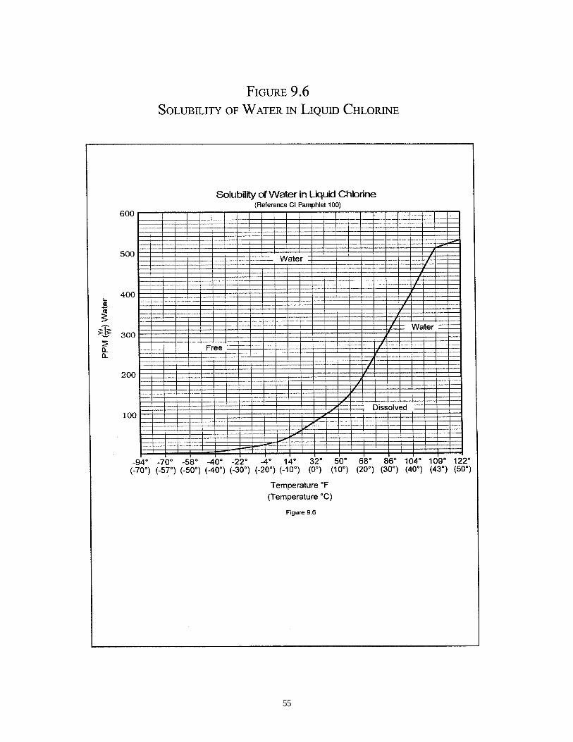
55

56
10.1 U.S. Government Regulations andSpecifications
All U.S. regulations and specificationsare available from the Superintendent ofDocuments, U.S. Government PrintingOffice, Washington, D.C. 20402.
10.1.1 Code of Federal Regulations (CFR),Various Sections
10.1.2 Chlorine Technical, Liquid; FederalSpecification BB-C 120 C.
10.2 Canadian Regulations
Most Canadian regulations can beobtained from the Canadian GovernmentPublishing Center, Supply and ServicesCanada, Ottawa, Canada K1A 059.
10.3 Chlorine Institute References
10.3.1 Pamphlets and InstructionalBooklets
5 Non-Refrigerated LiquidChlorine Storage
5 Piping Systems for Dry Chlorine
9 Chlorine Vaporizing Systems
17 Cylinder and Ton Container Proce-dures for Chlorine Packaging
21 Nitrogen Trichloride - A Collection ofReports and Papers
39 Maintenance Instructions for ChlorineInstitute Standard Safety Valves, Type1-1/2JQ
40 Maintenance lnstructions for ChlorineInstitute Standard Angle Valve
41 Maintenance Instructions for ChlorineInstitute Standard Safety Valves, Type4 JQ
42 Maintenance lnstructions for ChlorineInstitute Standard Excess Flow Valves
49 Handling Chlorine Tank MotorVehicles
57 Emergency Shut-Off Facilities for TankCar/Tank Truck Transfer of Chlorine
60 Chlorine Pipelines
63 First Aid and Medical Management ofChlorine Exposures
64 Emergency Response Plans forChlorine Facilities
65 Personal Protective Equipment forChlorine and Sodium Hydroxide
66 Recommended Practices for HandlingChlorine Tank Cars
72 Properties of Chlorine in SI Units
73 Atmospheric Monitoring Equipment forChlorine
10 SELECTED REFERENCES
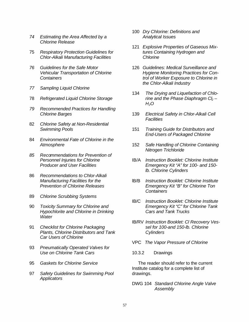
57
74 Estimating the Area Affected by aChlorine Release
75 Respiratory Protection Guidelines forChlor-Alkali Manufacturing Facilities
76 Guidelines for the Safe MotorVehicular Transportation of ChlorineContainers
77 Sampling Liquid Chlorine
78 Refrigerated Liquid Chlorine Storage
79 Recommended Practices for HandlingChlorine Barges
82 Chlorine Safety at Non-ResidentialSwimming Pools
84 Environmental Fate of Chlorine in theAtmosphere
85 Recommendations for Prevention ofPersonnel Injuries for ChlorineProducer and User Facilities
86 Recommendations to Chlor-AlkaliManufacturing Facilities for thePrevention of Chlorine Releases
89 Chlorine Scrubbing Systems
90 Toxicity Summary for Chlorine andHypochlorite and Chlorine in DrinkingWater
91 Checklist for Chlorine PackagingPlants, Chlorine Distributors and TankCar Users of Chlorine
93 Pneumatically Operated Valves forUse on Chlorine Tank Cars
95 Gaskets for Chlorine Service
97 Safety Guidelines for Swimming PoolApplicators
100 Dry Chlorine: Definitions andAnalytical Issues
121 Explosive Properties of Gaseous Mix-tures Containing Hydrogen andChlorine
126 Guidelines: Medical Surveillance andHygiene Monitoring Practices for Con-trol of Worker Exposure to Chlorine inthe Chlor-Alkali Industry
134 The Drying and Liquefaction of Chlo-rine and the Phase Diaphragm Cl2 –H2O
139 Electrical Safety in Chlor-Alkali CellFacilities
151 Training Guide for Distributors andEnd-Users of Packaged Chlorine
152 Safe Handling of Chlorine ContainingNitrogen Trichloride
IB/A Instruction Booklet: Chlorine InstituteEmergency Kit “A” for 100- and 150-lb. Chlorine Cylinders
lB/B Instruction Booklet: Chlorine InstituteEmergency Kit “B” for Chlorine TonContainers
IB/C Instruction Booklet: Chlorine InstituteEmergency Kit “C” for Chlorine TankCars and Tank Trucks
IB/RV Instruction Booklet: Cl Recovery Ves-sel for 100-and 150-lb. ChlorineCylinders
VPC The Vapor Pressure of Chlorine
10.3.2 Drawings
The reader should refer to the currentInstitute catalog for a complete list ofdrawings.
DWG 104 Standard Chlorine Angle ValveAssembly
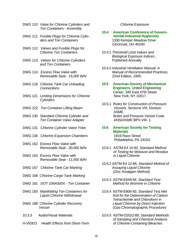
58
DWG 110 Valve for Chlorine Cylinders andTon Containers - Assembly
DWG 111 Fusible Plugs for Chlorine Cylin-ders and Ton Containers
DWG 112 Valves and Fusible Plugs forChlorine Ton Containers
DWG 113 Valves for Chlorine Cylindersand Ton Containers
DWG 114 Excess Flow Valve withRemovable Seat - 15,000 lb/hr
DWG 118 Chlorine Tank Car UnloadingConnections
DWG 121 Limiting Dimensions for ChlorineCylinders
DWG 122 Ton Container Lifting Beam
DWG 130 Standard Chlorine Cylinder andTon Container Valve Adapter
DWG 131 Chlorine Cylinder Valve Yoke
DWG 136 Chlorine Expansion Chambers
DWG 162 Excess Flow Valve withRemovable Seat - 30,000 lb/hr
DWG 163 Excess Flow Valve withRemovable Seat - 11,000 lb/hr
DWG 167 Chlorine Tank Car Marking
DWG 168 Chlorine Cargo Tank Marking
DWG 181 DOT 106A500X - Ton Container
DWG 183 Manifolding Ton Containers forLiquid Chlorine Withdrawal
DWG 188 Chlorine Cylinder RecoveryVessel
10.3.3 Audio/Visual Materials
H-VIDEO Health Effects from Short-Term
Chlorine Exposure
10.4 American Conference of Govern-mental Industrial Hygienists1330 Kemper Meadow DriveCincinnati, OH 45240
10.4.1 Threshold Limit Values andBiological Exposure Indices ,Published Annually
10.4.2 Industrial Ventilation Manual: AManual of Recommended Practices,22nd Edition, 1995.
10.5 American Society of MechanicalEngineers, United EngineeringCenter, 345 East 47th StreetNew York, NY 10017.
10.5.1 Rules for Construction of PressureVessels, Sections VIII, DivisionASMEBoiler and Pressure Vessel CodeANSI/ASME BPV-VIII- 1.
10.6 American Society for TestingMaterials1916 Race Street Philadelphia, PA 19103.
10.6.1 ASTM-E4 10-92, Standard Methodof Testing for Moisture and Residuein Liquid Chlorine
10.6.2 ASTM-E4 12-86, Standard Method ofAssaying Liquid Chlorine(Zinc Amalgam Method)
10.6.3 ASTM-E649-94, Standard TestMethod for Bromine in Chlorine
10.6.4 ASTM-E806-93, Standard Test Method for the Determination of CarbonTetrachloride and Chloroform inLiquid Chlorine by Direct Irqection(Gas Chromatographic Procedure)
10.6.5 ASTM-D2022-89, Standard Methodsof Sampling and Chemical Analysisof Chlorine-Containing Bleaches

59
10.7 American Water WorksAssociation6666 West Quincy AvenueDenver, CO 80235.
10.8 Association of AmericanRailroads50 F St., NWWashington, DC 20001
10.9 Compressed Gas Association1725 JeffersonDavis Highway, Suite1004 Arlington, VA 22202.
10.9.1 Handbook of Compressed GasesVan Nostrand Reinhold, New York,NY
10.9.2 Pamphlet C-i, Methodsfor HydrostaticTesting of Compressed GasCylinders
10.9.3 Pamphlet C-6, Standardsfor VisualInspection ofCompressed GasCylinders
10.9.4 Pamphlet P-i, Safe Handling of Com-pressed Gases in Containers
10.9.5 Pamphlet V-i, Compressed GasCylinder Valve Outlet and Inlet Con-nections (This pamphlet is alsodesignated as ANSI B57.1 and CSAb96.)
10.9.6 10.10 National Academy of Sciences
Printing and Publishing OfficeNational Academy of Sciences2101 Constitution Avenue, NWWashington, DC 20418.
10.10.1Water Chemicals Codex, 1982.
10.10.2 Food Chemicals Codex II, Fourth Edition, 1996
10.11 National Fire ProtectionAssociation Batterymarch Park,Quincy, MA 02269.
10.12 National Institute of OccupationalSafety and Health
10.12.1Pocket Guide to Chemical HazardsU.S. Department of Healthand Hmnan Services: 1994.
10.13 National Safety Council444 North Michigan AvenueChicago, IL 60610.
10.14 NSF lnternational3475 Plymouth RoadAnn Arbor, MI 48113
10.14.1ANSI/NSF Standard 60-Drinking Water Additives-HealthEffects; updated annually.
10.15 Water Environment Foundation601 Wythe StreetAlexandria, VA 22314
10.16 World Health OrganizationDistribution and Sales Service1211 Geneva 27, Switzerland
10.16.1Environmental Health Criteria 21Chlorine and Hydrogen Chloride,1982.
10.17 Chemical Industry Inst. ofToxicology6 Davis DriveResearch Triangle Park, NC 27709
10.17.1A Chronic Inhalation Study ofChlorine in Female and Male B6C3]Mice and Fischer344Rats; ChemicalIndustry Institute oftoxicology: 1993.
10.18 Other References
10.18.1 Adams, F. W.; Edmonds, R. G.; I&EC,1937, 29, 447.

60
10.18.2 Ambrose, D.; Hall, D. J.; Lee, D. A.;Lewis, G. B.; Mash, C. J. J.;Chemical Thermodynamics, 1979,11, 1089.
10.18.3Chlorine Bicentennial Symposium;Jeffery, T.; Danna, P. A.; Holden, H.S., Eds.; Electrochemical Sociely:Princeton, NJ, 1974.
10.18.4 Chlorine, Its Manufacture,Properties and Uses; Sconce, J. S.ed.; ACS Monograph 154; Robert E.Krieger: Huntington, NY, 1972.
10.18.5 Heinemann, G.; Garrison, F.G.;Haber, P.A.; I & EC. 1946, 38, 497.
10.18.6Interpretive Review of the PotentialAdverse Effects of ChlorinatedOrganicChemicals on Human Health and theEnvironment, Report of an ExpertPanel;Coulston, F. and Kolbye, A.C., Eds.;Regulatory Toxicology and Pharmacology Journal; Academic Press:New York, NY, 1994.
10.18.7 Alkali and Chlorine Products andChlorine and Sodium Hydroxide;Kirk-Othrner Encyclopedia ofChemical Technology; ed. 4; Editor:John Wiley & Sons, New York, NY,1991.
10.18.8 Kowitz, T. A.; Reba, R. C.; Parker,R. T.; Spicer, W. S.; Arch. ofEnvironmental Health, 1967, 14,545.
10.18.9 Modern Chlor-Alkali Technology;Jackson, C., Ed.; Society ofChemical Industry; John Wiley &Sons: New York, NY, 1983; Vol. 2.
10.18.10 Patty, F. A.; Industrial Hygiene andToxicology; Interscience: New York,NY.
10.18.11 Rotman, Harold H., etal.;Journal ofthe American PhysiologicalSociety, 1983, 1120, 983.
10.18.12 Weill, H.; George, R.; Schwartz,M.; Ziskind, M. ; Am. Review ofRespiratory Diseases, 1969, 29,373.
10.18.13 Weston, P.C. Modern Chlor-AlkaliTechnology; Coulter, M.O., et al,Eds.; Society of Chemical Industry;Royal Society of Chemistry:Cambridge, 1994; Vol.6, pp 62-69.
10.18.14 Grenquist-Norden, B.; Institute ofOccupational Health, 1983, pp 1-83.

CHLORINE
The Essential Element
Over 200 years ago, a young Swedish researcher, Carl Wilhelm Scheele,discovered chlorine. Because of its reactivity and bonding characteristics, chlorinehas become a popular building block in chemistry and it is essential in everyone’slife. Drinking water, agricultural abundance, disinfected waste water, essentialindustrial chemicals, bleaches and fuels all depend on chlorine. Pharmaceutical,plastics, dyes, cosmetics, coatings, electronics, adhesives, clothing and automobileparts are examples of product groups that depend on chlorine chemistry.
APPLICATIONS OF CHLORINE
AutomotiveFoam SeatingPaintsPlastic Bumpers MoldingInstrumentsFloor MatsFabricSeat BeltsTire CordsDashboardsHoses
ConstructionCarpetingUpholsteryWire InsulationPipesSidingFlooringPaintsCoatings
DefenseBullet-Proof VestsHelmetsParachutesWater Repellant FibersShatter-Resistant GlassTitanium AircraftJet EnginesMissiles
ElectronicsSemiconductorsComputer DisksWire Insulation
Food Production& HandlingHerbicidesVitamins B1 & B6CleanersDisinfectantsThermal InsulationSterile Packaging
Health CareElectronic InstrumentsSterile PackagingSurgical EquipmentCleaning CompoundsPrescription Eye WearLaboratory Reagents
MedicinesAntibioticsCancer TreatmentPain RelieversLocal AnestheticsAntihistaminesDecongestants
Metal ProductionMagnesiumNickelBismuthTitaniumZirconiumZinc
Outdoor RecreationNeoprene Wet SuitsInflatable RaftsGolf GripSurf BoardsNylon RopesTentsSleeping BagsCoatsBackpacksWaterproof Clothing
Water TreatmentSafe Drinking WaterWastewater Treatment

Chlorine Institute Pamphlet 1, Edition 6 January 1997 Second Printing March 2000
Topics in this manual include: Chlorine and . . .
Bulk Shipments First AidContainers MaintenanceEmergencies ReferencesEmployee Safety RegulationsEngineering Technical DataEnvironment Training