the central campus - ocsrocsr.fnal.gov/files/master_plan/thetechnicalcampus.pdf · the central...
TRANSCRIPT

The Central
Campus

59 f e r m i l a b c a m p u s m a s t e r p l a n the campus plan
Central Campus today
The Central Campus is the focal point of the Fermilab Campus and is the most densely populated and active of the regions. Existing facilities are Wilson Hall, Ramsey Auditorium, the “Footprint Area,” the Lederman Science Education Center and noted sculptures designed by Robert Wilson.
Wilson Hall is the most prominent building at Fermilab. It provides laboratories and offices for researchers, staff and visiting scientists. It also contains administrative offices, the Office of Communication, a cafeteria, a library and a wide variety of conference and meeting rooms.
Ramsey Auditorium seats approximately 800 in a steeply sloping configuration. The auditorium was specifically designed for meetings of the physicists and staff and for the exchange of scientific information. The facility also presents a regular, popular program of musical and cultural events.
The Leon M. Lederman Science Education Center is the focal point for Fermilab educational outreach to the surrounding communities. It houses the K-12 Teacher Resource Center and hands-on exhibits designed for middle school field trips, and it is available to the general public. The building also houses a gift shop.
The "Footprint Area” refers to the complex of one-story buildings south of Wilson Hall. This complex houses the Main Control Room, various shops, technical spaces and offices. The Campus Plan calls for the demolition of these inadequate founding-era structures and for redevelopment on the sites.
Sculpture: Two large pieces of sculpture designed by Robert Wilson are located in the Central Campus. One is the Mobius strip (shown), which is mounted in the midst of a circular pool atop Ramsey Auditorium. The other is the Hyperbolic Obelisk, which stands at the foot of the reflecting pond in front of Wilson Hall.
Central Campus Key Plan

Central Campus today
4
2
3
legend
1 Wilson Hall
2 Ramsey Auditorium
3 Footprint Area
4 Lederman Center
5 Central Utility Building
1
5

61 f e r m i l a b c a m p u s m a s t e r p l a n the campus plan
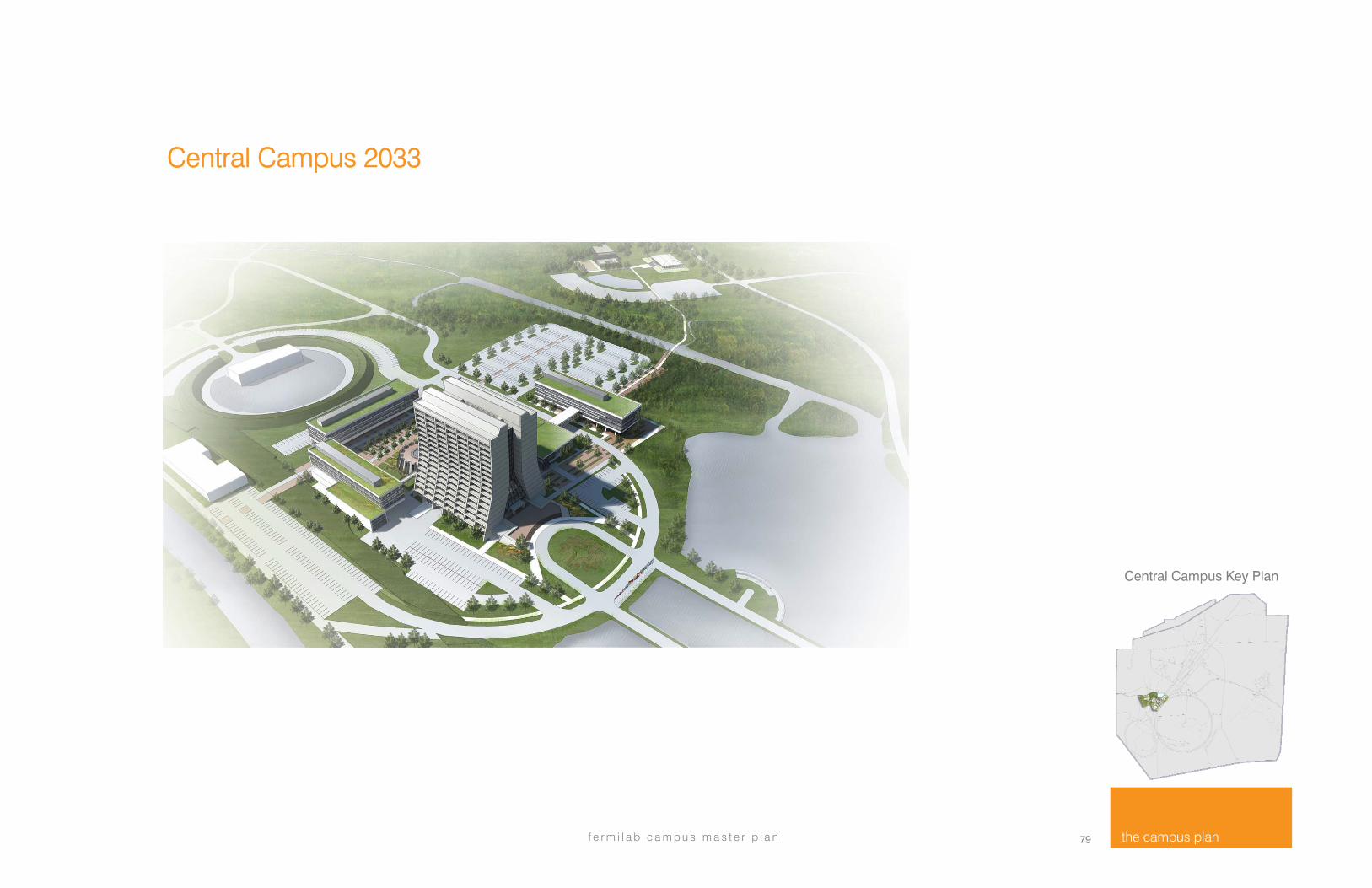
Central Campus 2033
legend
1 Wilson Hall 2.0
2 The Center for Integrated Engineering Research (includes Collision hall)
3 Future Development
4 The Courtyard
5 Scientific Hostel
6 Central Utility Building (CUB)
5
1
2
3
4
Central Campus Key Plan
2
3
3
6

Central Campus future projects
Future developments in the Central Campus will significantly improve the region. They will result in the creation of a vibrant and interconnected Central Campus anchored by Wilson Hall.
The reimagined Campus will consist of :
1) The Center for Integrated Engineering Research (IER)
2) The Collision Hall connecting the IER to Wilson Hall
3) An outdoor Courtyard unifying the elements and providing useable outdoor spaces.
4) Imagined long range developments to the south of Wilson Hall accommodating future consolidation projects.
These developments combine to result in a reinvigorated Central Campus region in a unified Campus setting. The resulting Campus will provide a clear entrance, bringing people together. Additionally, the Central Campus will provide reimagined vehicular and pedestrian amenities designed to improve and enhance the total Central Campus experience.
An additional proposed element of the central Campus region is the Scientific Hostel (5), located near the Lederman Science Education Center.
1
2
5
4 3

63 f e r m i l a b c a m p u s m a s t e r p l a n the campus plan
The Center for Integrated Engineering Research (IER) is the anchor component to the Central Campus developments. It will promote interdisciplinary collaboration and greater efficiency in designing, developing, building, commissioning, and operating particle physics accelerator and detector facilities and equipment.
The Collision Hall is another core component of the revitalized Central Campus. It will provide interior connections between Wilson Hall and the developments to the west. It will be a hub of activity and energy where staff and visitors “collide” and come together. The building will serve as a main entrance to the complex for staff and visitors, while also providing much needed space for conferencing, collaboration and interaction.
The Courtyard is envisioned as part of the longer range development of the central Campus. It will be a vibrant outdoor gathering space linking possible future development sites. Its prime location, on land currently occupied by parking, will place it at the center of these developments.
Central Campus Key Plan

The Center for Integrated Engineering Research
The purpose of the Center for Integrated Engineering Research (IER) Building is to establish a new facility that promotes interdisciplinary collaboration and greater efficiency in designing, developing, building, commissioning, and operat ing par t ic le phys ics accelerator and detector fac i l i t ies and equipment . As America’s particle physics and accelerator laboratory, Fermilab is the DOE Office of Science national laboratory for particle physics research. By replacing outdated laboratory space and obsolete facilities, the IER will revitalize and streamline research in particle physics for the benefit of the particle physics community and the DOE Office of Science. The IER will consolidate engineering and technical teams in a collaborative environment that brings together engineering disciplines from Fermilab’s Accelerator Division, Particle Physics Division, and Scientific Computing Division. This will facilitate interdisciplinary collaboration by building on existing laboratory capabilities and expertise, currently dispersed across the Fermilab site. The IER will serve the needs of the DOE Office of Science without duplicating capabilities at other national laboratories and is necessary to implement the recommendations of the Particle Physics Projects Prioritization Panel (P5). The IER will establish a unique capability not only for intellectual collaboration but also for design and execution of the experiments required to explore neutrino-nucleus scattering, high power target research and development and other activities, which are key precursors to a long baseline neutrino program hosted at Fermilab. The name “Integrated Engineering Research” expresses three aspects of integration that guide the development of the IER. The first of these is to integrate engineering disciplines that are involved in the development of accelerator and detector technology. Engineers and technicians from the Fermilab Accelerator Division (AD) will be collocated in an
engineering building together with engineers and technicians from the Particle Physics Division (PPD) and Scientific Computing Division (SCD). The engineering building will provide office space and shared lab space for personnel from these divisions thereby addressing inefficiencies caused by having people dispersed across the Fermilab site. The IER addresses a second aspect of integration that brings together engineers and scientists that contribute to and benefit from the development of accelerator and detector technology. In this regard the IER functions as a user facility that promotes better integration of engineering and science activities devoted to accelerator and detector technology. This is accomplished by locating the engineering building in close proximity to Wilson Hall, which serves as the centralized location for the scientific user community at the Laboratory to create the “eat-sleep-work to drive discovery” atmosphere. A third type of integration addresses the lifecycle of accelerator and detector technology development from conceptual design to operations. This is accomplished by including the needs of engineers, scientists, and technicians involved in the design and construction of accelerator and detector technology together with the needs of the personnel involved in accelerator and detector support and operations. Specifically, the proximity of the expertise concentrated by construction of the IER near the operating accelerator complex can enable system design, development, and component testing needs and requirements for the critical PIP-II accelerator project upgrades, another of the highest priorities of the P5 report, to be most effectively met.

65 f e r m i l a b c a m p u s m a s t e r p l a n the campus plan
The illustration above shows the proposed Center for Integrated Engineering Research, in the context of a long term vision that includes future possible development sites. The prime location for these possible developments is currently occupied by obsolete facilities, surface parking and roadways. The unification of groups and functionality into the Central Campus will foster the desired synergy and collaboration both within and across the disciplines located there. The project, augmenting the planned IER will create additional modern, open buildings; continuing to place Fermilab on par with leading research institutions around the world.
legend
1 Wilson Hall 2.0
2 IER and Collision Hall
3 Long Range future development sites
4. The Courtyard
1 2
3
4
IER, Collision Hall and Courtyard shown highlighted
3
“
The IER will establish a unique capability not only for intellectual collaboration, but also for design and execution of the experiments required to explore neutrino-nucleus scattering, high power target research and development and other activities, which are key precursors to a long baseline neutrino program hosted at Fermilab.

The Collision Hall
Among the guiding principles for the Campus Plan are “enhancing the Campus experience” and “reinforcing community.” The Collision Hall is a key element in the response to those goals and will become the vital core of the Campus. It will connect Wilson Hall with the new IER building to the west. It will contain formal and informal collaboration spaces and a variety of informal work settings. As a place for meeting and inspiration, the Collision Hall provides daylight and unobstructed views to Swan Lake and the woods to the north. The collision hall provides many opportunities for meeting and work.

67 f e r m i l a b c a m p u s m a s t e r p l a n the campus plan
Cutaway view looking down from the northwest at Wilson Hall, the Collision Hall, and the Center for Integrated Engineering Research. All buildings are removed from the second floor up to show the relationships of the interior spaces. The Wilson Hall atrium and cafeteria are on the left. Meeting space will be located on the main floor of the Collision Hall. The floor below will have an inviting entrance, a display area, and a conference center for 300 people.
legend
1 Wilson Hall atrium
2 Collision Hall
3 Display
4 Conference center below
5 Visitors entrance
6 Meeting rooms
7 Center for Integrated Engineering Research
Central Campus Key Plan
1
2
3
4 5
6
7
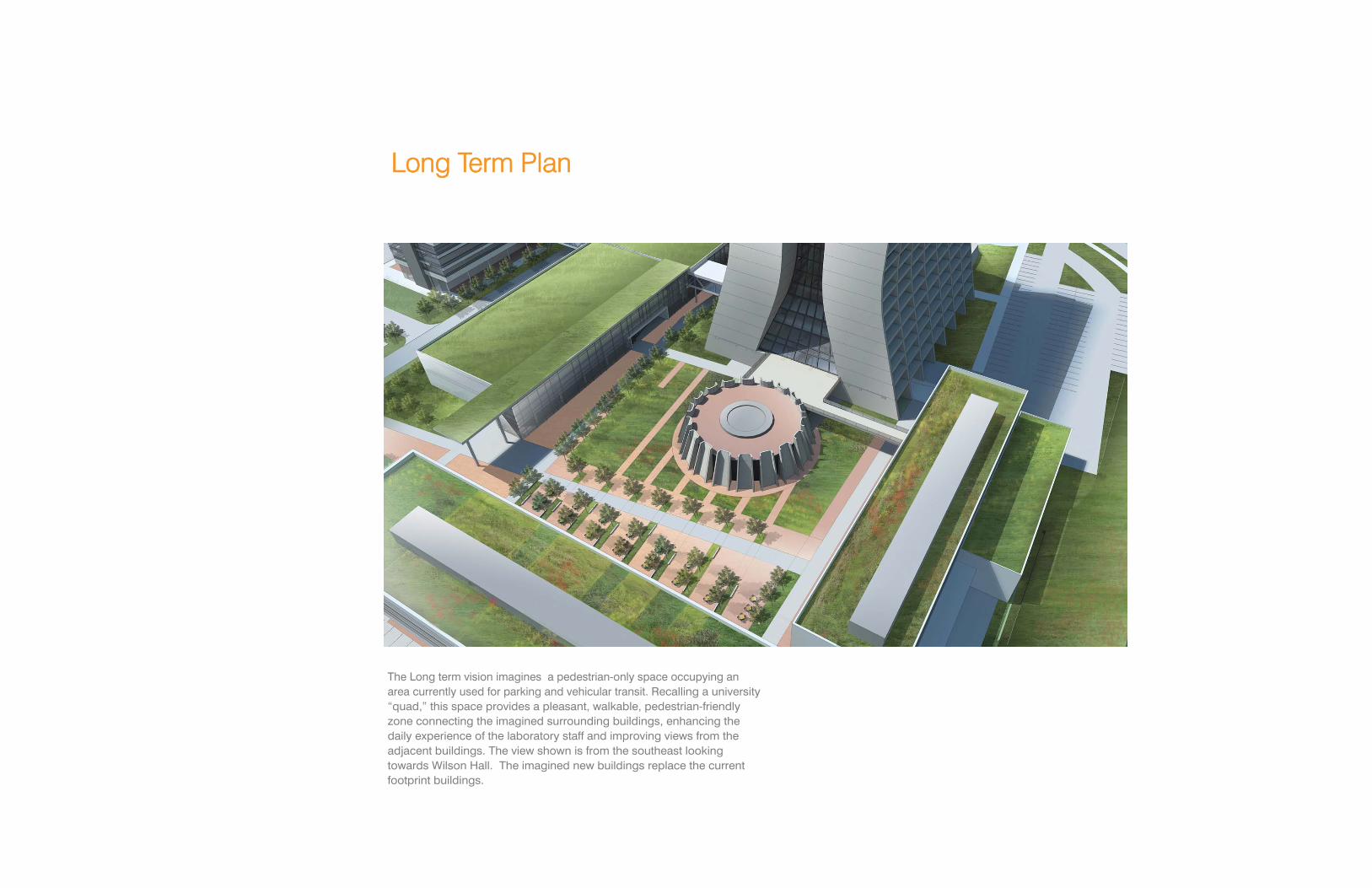
Long Term Plan
The Long term vision imagines a pedestrian-only space occupying an area currently used for parking and vehicular transit. Recalling a university “quad,” this space provides a pleasant, walkable, pedestrian-friendly zone connecting the imagined surrounding buildings, enhancing the daily experience of the laboratory staff and improving views from the adjacent buildings. The view shown is from the southeast looking towards Wilson Hall. The imagined new buildings replace the current footprint buildings.

69 f e r m i l a b c a m p u s m a s t e r p l a n the campus plan
The Quad will contain a mix of hardscape and landscape areas to accommodate a spectrum of activities. Seating, tables and other amenities will be integrally designed to create a human-scaled, inviting place in which to meet, eat, think or work. Additionally, it will be spacious enough to accommodate large outdoor lab-wide events and gatherings.
Central Campus Key Plan
“
A building is not just a place to be, it is a way to be.” Frank Lloyd Wright

“There’s a temptation in our networked age to think that ideas
can be developed by email and iChat. That’s crazy. Creativity
comes from spontaneous meetings, from random discussions. You run
into someone, you ask what they’re doing, you say ‘Wow,” and soon
you’re cooking up all sorts of ideas...Interaction equals
Innovation" Steve Jobs

71 f e r m i l a b c a m p u s m a s t e r p l a n the campus plan
The Collision Hall
71
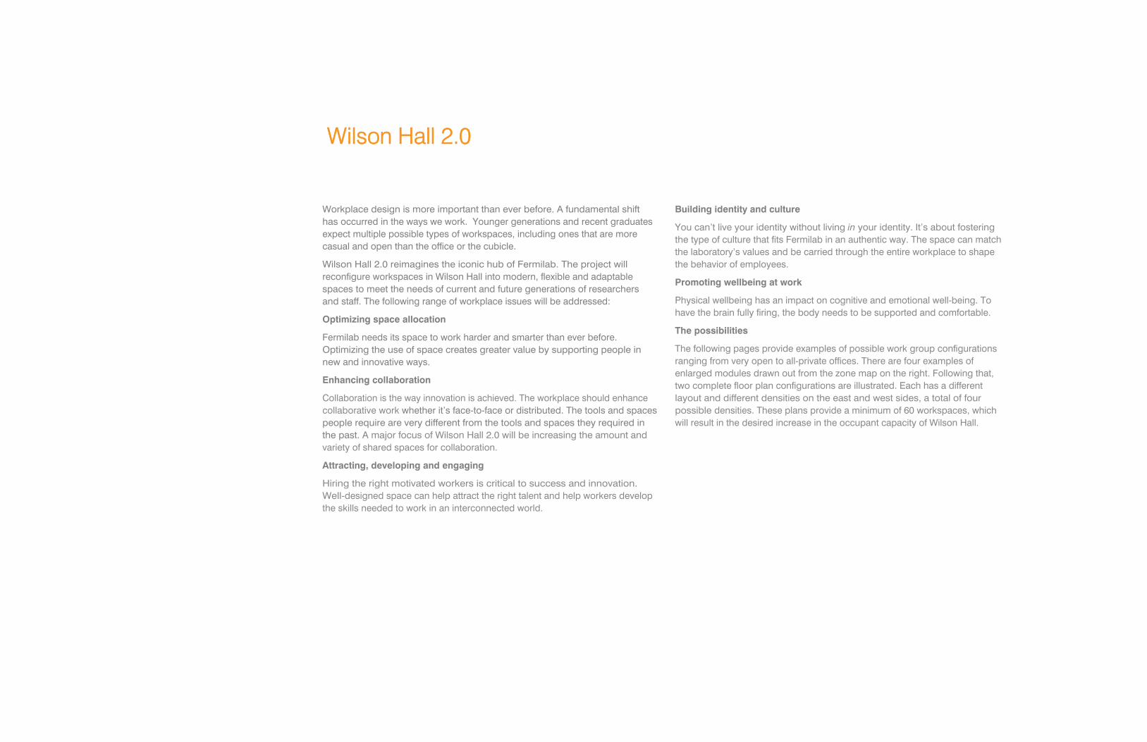
Wilson Hall 2.0
Workplace design is more important than ever before. A fundamental shift has occurred in the ways we work. Younger generations and recent graduates expect multiple possible types of workspaces, including ones that are more casual and open than the office or the cubicle.
Wilson Hall 2.0 reimagines the iconic hub of Fermilab. The project will reconfigure workspaces in Wilson Hall into modern, flexible and adaptable spaces to meet the needs of current and future generations of researchers and staff. The following range of workplace issues will be addressed:
Optimizing space allocation
Fermilab needs its space to work harder and smarter than ever before. Optimizing the use of space creates greater value by supporting people in new and innovative ways.
Enhancing collaboration
Collaboration is the way innovation is achieved. The workplace should enhance collaborative work whether it’s face-to-face or distributed. The tools and spaces people require are very different from the tools and spaces they required in the past. A major focus of Wilson Hall 2.0 will be increasing the amount and variety of shared spaces for collaboration.
Attracting, developing and engaging
Hiring the right motivated workers is critical to success and innovation. Well-designed space can help attract the right talent and help workers develop the skills needed to work in an interconnected world.
Building identity and culture
You can’t live your identity without living in your identity. It’s about fostering the type of culture that fits Fermilab in an authentic way. The space can match the laboratory’s values and be carried through the entire workplace to shape the behavior of employees.
Promoting wellbeing at work
Physical wellbeing has an impact on cognitive and emotional well-being. To have the brain fully firing, the body needs to be supported and comfortable.
The possibilities
The following pages provide examples of possible work group configurations ranging from very open to all-private offices. There are four examples of enlarged modules drawn out from the zone map on the right. Following that, two complete floor plan configurations are illustrated. Each has a different layout and different densities on the east and west sides, a total of four possible densities. These plans provide a minimum of 60 workspaces, which will result in the desired increase in the occupant capacity of Wilson Hall.

73 f e r m i l a b c a m p u s m a s t e r p l a n the campus plan
Typical floor zone diagram
Legend
Central Campus Key Plan
Identity Space will enhance group identity, drawing others into who the group is and the work that they perform.
Open and closed offices
Conferencing and collaboration
Printers, technology and copiers
Circulation
The floor plan above is a typical plan of one of the upper floors of Wilson Hall (floors 8 through 15). The reimagined configurations for this building are based on the zoned concept illustrated above. The grid shown is a 2-foot-by-2-foot square and provides an organizing system for the modular “kit of parts” system of full-height and lower height partitions and furnishings.

Wilson Hall 2.0 module examples
Creating “palates of place,” this layout module combines private offices with open workspaces and open team “huddle” spaces. The huddle on the left illustrates how a wall mounted video screen could be utilized for shared viewing.
This module illustrates an approach leaning toward maximum capacity. It could accommodate staff that may be telecommuters or transient consultants or university collaborators. Note that in all of the layouts, the high elements are positioned perpendicular to views and daylight sources for maximization of those assets. Walls parallel to the daylight and views are translucent.
1 2
75 f e r m i l a b c a m p u s m a s t e r p l a n the campus plan
Central Campus Key Plan
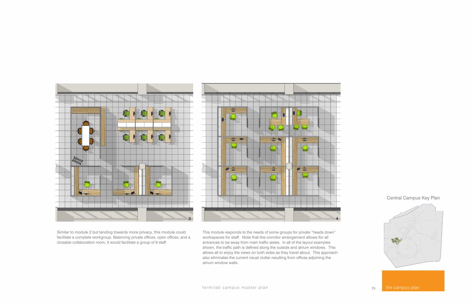
Similar to module 2 but tending towards more privacy, this module could facilitate a complete workgroup. Balancing private offices, open offices, and a closable collaboration room, it would facilitate a group of 9 staff.
This module responds to the needs of some groups for private “heads down” workspaces for staff. Note that the corridor arrangement allows for all entrances to be away from main traffic aisles. In all of the layout examples shown, the traffic path is defined along the outside and atrium windows. This allows all to enjoy the views on both sides as they travel about. This approach also eliminates the current visual clutter resulting from offices adjoining the atrium window walls.
3 4
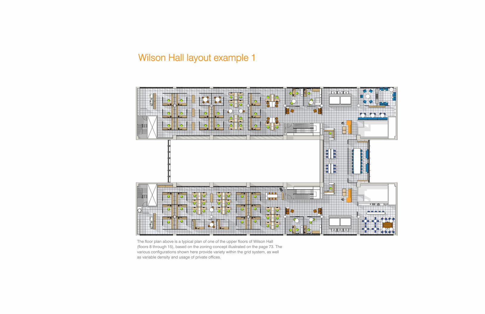
Wilson Hall layout example 1
The floor plan above is a typical plan of one of the upper floors of Wilson Hall (floors 8 through 15), based on the zoning concept illustrated on the page 73. The various configurations shown here provide variety within the grid system, as well as variable density and usage of private offices.

77 f e r m i l a b c a m p u s m a s t e r p l a n the campus plan
Wilson Hall layout example 2
Central Campus Key Plan
The grid system and the modularity of the wall and furniture systems provide almost limitless possibilities for easily changeable and adaptable space layouts and combinations.
“
We shape our buildings, thereafter they shape us” Winston Churchill

Scientific Hostel
The Scientific Hostel is a 60-room hostel to house visiting collaborators. It will also contain small meeting rooms and lounge space. This project augments the 200-plus housing units currently available in the Village.
The hostel’s location within the Central Campus is an ideal setting for convenient collaboration and integration into the Fermilab life. It is a short walk through the nearby woods to reach Wilson Hall and the new developments at the Center Campus.
1
2
legend
1 Lederman Science Education Center
2. Scientific Hostel
79 f e r m i l a b c a m p u s m a s t e r p l a n the campus plan
Central Campus Key Plan
Central Campus 2033

Central Campus 2033

81

The Technical Campus

83 f e r m i l a b c a m p u s m a s t e r p l a n the campus plan
The Technical Campus today
The Technical Center consists of a complex of 5 major structures along with a number of ancillary buildings and structures. The photo (far left) depicts the Industrial Center Building. This precast concrete structure contains the premier high-bay assembly area on the Fermilab site. It has been used for the construction of magnets for the P-Bar Source, Main Injector and LHC; for the construction of the CDF end plug; and now for the construction of superconducting radio-frequency cryomodules. The building also houses Division leadership and administration. The photo to the immediate left is one of the four similar industrial buildings known as IB-1, IB‑2, IB‑3, and IB‑4. These four are early era facilities, all featuring both a high bay and equipment for assembly, processing and testing of magnets, SRF cavities, and other components. All four also have offices for a variety of staff.
The Illinois Accelerator Research Center (IARC): This recently completed building is a state-of-the-art facility for research, development, and industrialization of particle accelerator technology. Its focus is on developing partnerships with private industry for the commercial and industrial application of accelerator technology.
The former Collider Detector Facility (CDF) (orange building on left side of photo) is connected to the new IARC facility and is currently under refurbishment to become an integral part of the IARC program. The building was built for the assembly and operation of the CDF detector. As of this writing, the exceptionally high assembly area is being used for fabrication of the NOvA Near Detector modules. Both the industrial and office space will become part of the IARC facility.
Technical Campus Key Plan

The Technical Campus today
4
5
3
6
9 8
10
1
7
11
2
legend
1 Industrial Building 2 (IB-2)
2 Portakamps
3 Industrial Building 3 (IB-3)
4 Industrial Center Building (ICB)
5 Industrial Building 1 (IB-1)
6 Industrial Building 4 (IB-4)
7 Central Helium Liquefier (CHL)
8 IARC / OTE
9 CDF
10 CDF Portakamp Complex
11 Building 327

85 f e r m i l a b c a m p u s m a s t e r p l a n the campus plan
The Technical Campus 2033
13
14
12
4
5
3
6
9 8
15
1
7
legend
1 Industrial Building 2 (IB-2)
2 Former portacamp location
3 Industrial Building 3 (IB-3)
4 Industrial Center Building (ICB)
5 Industrial Building 1 (IB-1)
6 Industrial Building 4 (IB-4)
7 Central Helium Liquefier (CHL)
8 IARC / OTE
9 CDF
10 Former location of CDF trailers
11 Building 327
12 Industrial Center Building Addition
13 Industrial Center Building Gateway
14 Reworked Courtyard
15 Central Fabrication Facility (CFF)
11
Technical Campus Key Plan

Technical Campus future projects
1
5
12
4
13
3
7
6
9
8
14
15
legend
1 Industrial Building 2 (existing)
2 Portakamps (removed)
3 Industrial Building 3 (existing)
4 Industrial Center Building (ICB) (existing)
5 Industrial Building 1 (existing)
6 Industrial Building 4 (existing)
7 Central Helium Liquefier (CHL) (existing)
8 IARC (recent existing)
9 CDF (existing)
10 CDF Portakamp Complex (removed)
11 Building 327 (not shown)
12 Industrial Center Building Addition
13 Industrial Center Building Gateway
14 Reworked Courtyard
15 Central Fabrication Facility (CFF)

87 f e r m i l a b c a m p u s m a s t e r p l a n the campus plan
Industrial Center Building Addition: A new high-bay building, attached to the north side of ICB, will provide a flexible assembly space comparable to the existing space in ICB. This will allow simultaneous construction of more than one type of large component for accelerator and detector projects under development. The trailers currently scattered in the north parking lot will be removed, and the occupants transferred to ICB and the new Administrative Center.
Central Fabrication Facility (CFF): This new facility will replace the current remote, obsolete machining facilities in the Village with a modern, climate-controlled shop integrated into the Technical Campus. The residents of the Technical Campus, as well as the Central Campus, will benefit in many ways from the closer location.
Industrial Center Building Gateway: This new Administrative Center is intimately connected to ICB. It provides transparency for visitors and a more functional organization of offices for management, engineers and scientists. The entrance will clearly lead to key destinations within the buildings. The additional floor space will offset the space lost to the demolition of the Industrial Area trailers and a small expansion of staff.
Technical Campus Key Plan
CDF Refurbishment: This project will upgrade portions of the CDF building to incorporate the life safety upgrades, modernization of systems and building infrastructure for the continued use of the CDF building for IARC. It includes improvements to the overhead crane, provides security upgrades, and upgrades to the support bay necessary to provide modernized space to be used for office, technical and meeting spaces.

Central Fabrication Facility
The Central Fabrication Facility (CFF) project will be located on the site east of CDF that is currently occupied by 26,000 square feet of portacamps. This building will bring together workspaces currently housed in obsolete Village facilities.

89 f e r m i l a b c a m p u s m a s t e r p l a n the campus plan
View from the Technical Campus courtyard looking northwest toward IB-1. This view shows the proposed Industrial Center Gateway (ICG) Administration Center building directly in front of and attached to the existing Industrial Center Building.
Industrial Center Building Gateway
Technical Campus Key Plan

Technical Campus 2033

91 f e r m i l a b c a m p u s m a s t e r p l a n the campus plan 91

The Muon Campus
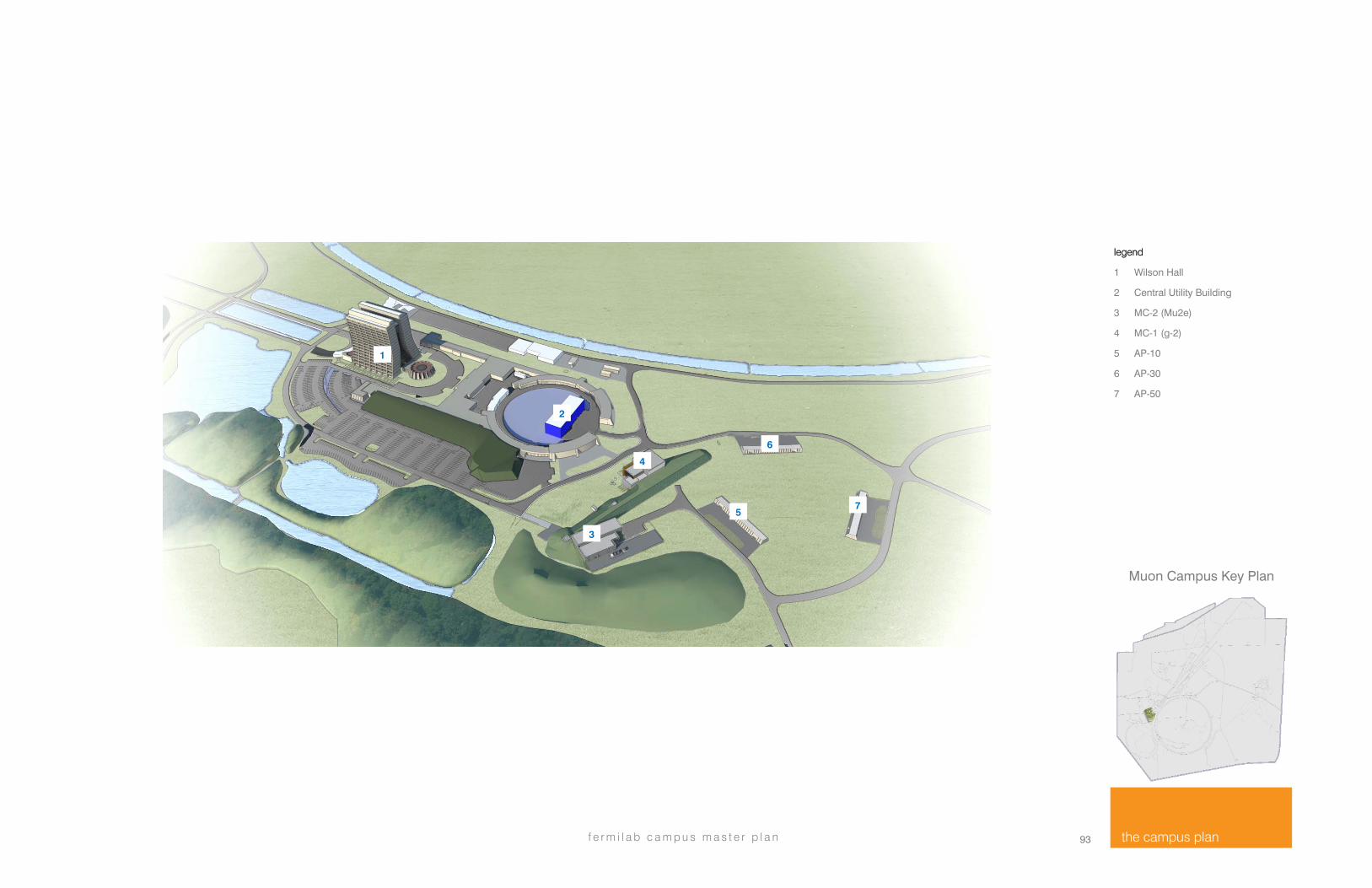
The new Muon Campus at Fermilab will consist of the reconfigured Antiproton Source, which will provide high-intensity muon beams to experiments, and two new buildings: MC-1 (shown below nearing completion), which will host the Muon g-2 experiment, and MC-2, which will host the Mu2e experiment. The new buildings will be located south of Wilson Hall, between the Booster accelerator and the former Antiproton Source. The campus development will include a berm from the reconfigured Antiproton Source beamline enclosure along with relocated roadways and more earth berming. The site also includes the existing antiproton buildings, AP-10, AP-30, and AP-50.
2 3
4
5
6
7
93 f e r m i l a b c a m p u s m a s t e r p l a n the campus plan
Muon Campus Key Plan
legend
1 Wilson Hall
2 Central Utility Building
3 MC-2 (Mu2e)
4 MC-1 (g-2)
5 AP-10
6 AP-30
7 AP-50
6
5 7
4
2
3
1

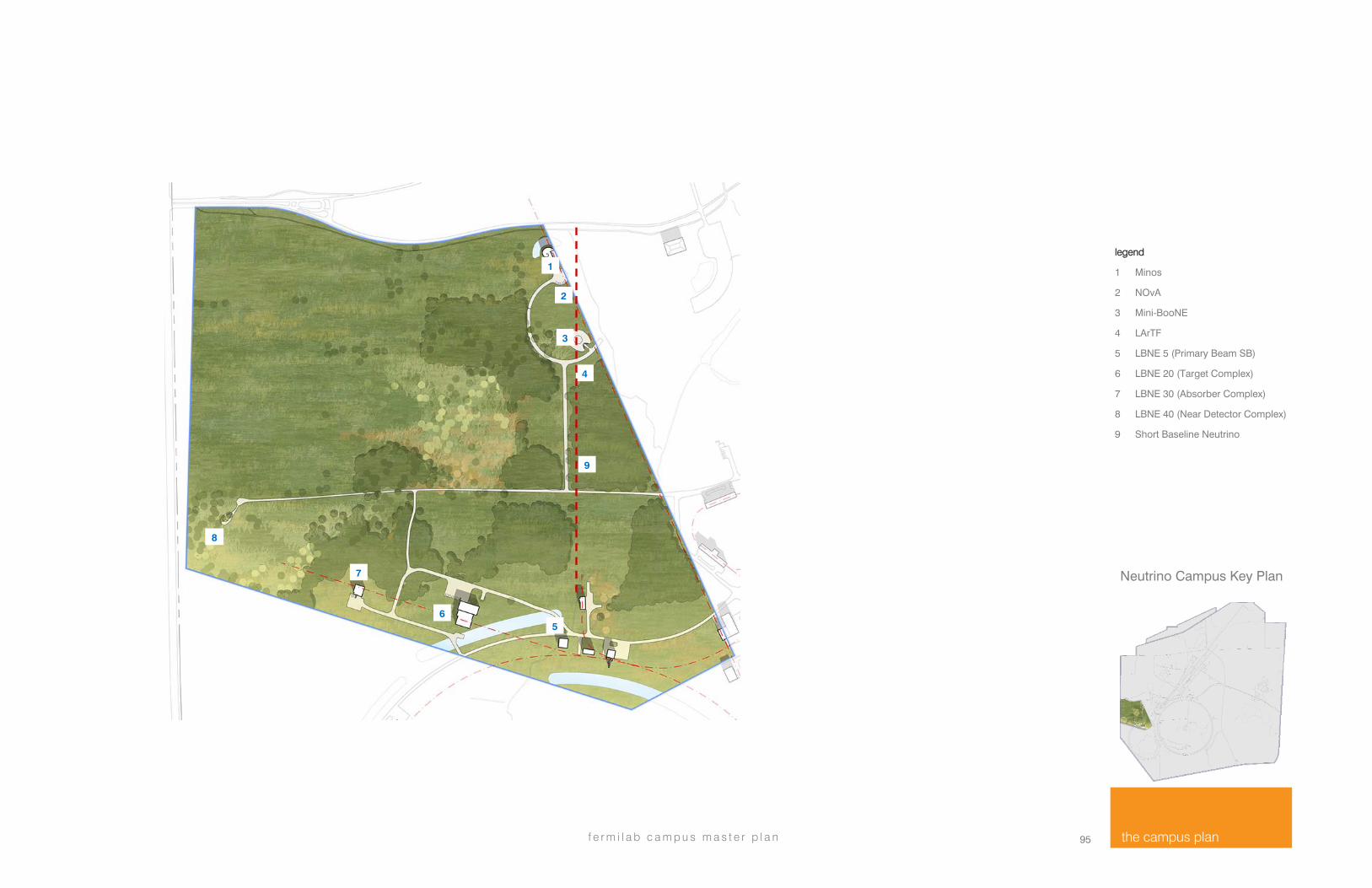
The Neutrino Campus
The Neutrino Campus is a newly defined campus region that will incorporate existing experiments and the proposed LBNE experiment into a unified neutrino focus region. The existing experiments are:
The Main Injector Neutrino Oscillation Search (MINOS) experiment is a long-baseline neutrino experiment designed to observe the phenomena of neutrino oscillations.
The Booster Neutrino Experiment (BooNE) is designed to verify definitively the results of the Los Alamos Liquid Scintillator Neutrino Detector experiment.
The MiniBooNE experiment explores physics topics from the fundamental understanding of neutrino interaction probabilities to more exotic matters, such as neutrinos from supernovae and the neutrino magnetic moment.
The MicroBooNE experiment will use a 70-ton liquid argon time-projection chamber (LArTPC) to examine neutrino beams at Fermilab.
The MINERvA experiment is a neutrino-scattering experiment that uses the NuMI beamline at Fermilab to search for low-energy neutrino interactions.
The NuMI Off-axis Electron Neutrino Appearance experiment (NOvA) will search for evidence of muon-to-electron neutrino oscillation and will study the properties of the elusive particles.
The Long Baseline Neutrino Experiment (LBNE) is a proposed world-class program in neutrino physics that would measure fundamental physical parameters to high precision and explore physics beyond the Standard Model. The measurements LBNE would make would greatly increase our understanding of neutrinos and their role in the universe, thereby better elucidating the nature of matter and anti-matter. LBNE would require the construction of six or seven surface buildings and a large berm. The scope of the Campus development would include additional roadways and access from the Central Campus and site configurations to accommodate the new facilities.
LBNE near Kirk Road
Minos LArTF Nova
95 f e r m i l a b c a m p u s m a s t e r p l a n the campus plan
Neutrino Campus Key Plan
legend
1 Minos
2 NOvA
3 Mini-BooNE
4 LArTF
5 LBNE 5 (Primary Beam SB)
6 LBNE 20 (Target Complex)
7 LBNE 30 (Absorber Complex)
8 LBNE 40 (Near Detector Complex)
9 Short Baseline Neutrino
1
3
2
4
6
8
7
5
9

The Superconducting Linac Complex
The Superconducting Linac Complex (SCLC) is a set of improvements to the existing accelerator complex that will provide high power proton beams in support of the Fermilab particle physics research program. The SCLC comprises the construction of a new 800 MeV superconducting linear accelerator injecting into the existing Booster/Recycler/Main Injector complex. Upon the completion of PIP-II the existing 400 MeV linear accelerator will be retired from service. The immediate goal of SCLC is to provide more than 1 MW of proton beam power onto the LBNE neutrino production target (the PIP-II Experiment facility) The secondary goal is to provide a platform for long term development of the Fermilab complex to support higher beam power to LBNE and to support a broader research program based on high power proton beams.

97 f e r m i l a b c a m p u s m a s t e r p l a n the campus plan
legend
1 Center Service Building (PIP-II)
2 3-8 GeV Pulsed Linac
3 1-3 GeV CW Linac
4 0-1 GeV CW Linac (PIP-II)
5 Cryo Building
Superconducting Linac Complex Key Plan
1
2
3
4
5