the cavity em and mechanical design issues and...
TRANSCRIPT

The cavity EM and mechanical design
issues and status
PIP-II meeting, 09/16/2014
Timergali Khabiboulline

2 9/16/2014 PIP-II meeting
• Difference between CW (Project X) and Pulsed (PIP-II)
linacs
• Cavities for PIP II:
- Normal conducting cavities: RFQ and Re-Buncher
- SRF cavities: HWR, SSR1, SSR2, 650 MHz (beta
= 0.61, beta = 0.92),
• Cavity Types and General Parameters
• Cavity Functional Specification
• Cavity Design Status
3 9/16/2014 PIP-II meeting
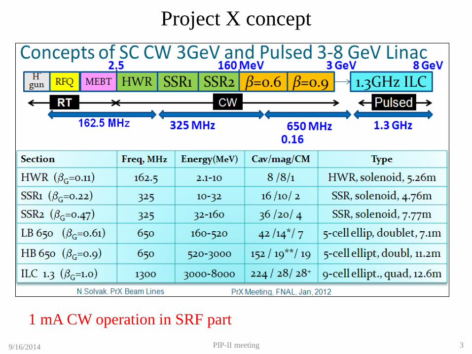
Project X concept
1 mA CW operation in SRF part

4 9/16/2014 PIP-II meeting
PIP-II concept
2 mA pulsed beam with duty factor from 0 to CW operation
Number of cavities/cryomodules changed for SSR2 and above
Pulsed

9/16/2014 PIP-II meeting 5
PIP-II cryogenics
~75% of cryogenic losses take place in 650 MHz part

6 9/16/2014 PIP-II meeting
General Issues:
• Low beam loading → narrow cavity bandwidth →
microphonics
• Beam current: 1mA →2 mA
• Lorentz Force Detuning (LFD) is an issue in a pulsed
mode, and should be analyzed for each cavity type.
• Future CW operation → cryo-losses → high Q0 is
desired. Technology of the cavity processing based on N-
doping is developing

7 9/16/2014 PIP-II meeting
Microphonics SRF cavities
Section Freq
MHz
Maximal
detune
(peak Hz)
Minimal
Half
Bandwidth (Hz)
Max Required
Power
(kW)
HWR 162.5 20 34 4.8
SSR1 325 20 45 5.3
SSR2 325 20 27 17.0
LB650 650 20 29 33.0
HB650 650 20 31 48.5
Bandwidth and required power optimized for CW (2 mA)
Microphonics Control Strategies: • Adding RF power to compensate for the expected peak frequency detuning.
• Minimizing Helium bath pressure peak to peak variations.
• Reducing df/dP , the sensitivity of the cavity resonant frequency to in the helium bath
pressure.
• Minimizing acoustics from external sources.
• Active compensation using a fast tuner driven by feedback from measurements of the
cavity resonant frequency.

8 9/16/2014 PIP-II meeting
Room temperature cavities. RFQ.
Input cut back Tuners and pi-mode rods Vanes Output cut back
Mechanical Design Complete 3D model
As a part of PXIE RFQ design team we performed:
• Overall RF designs of the PXIE RFQ and IMP RFQ – shape of vanes, positions and dimensions of the tuners and the
PISLs, shape and dimension of the end cut-backs etc.
• RF and mechanical design of the novel power couplers.
• Error analysis for the main parameters, impact of the vane modulations on the frequency and field distributions.
• RF losses evaluation and basic thermal analysis.
• Multipacting simulations in the RFQ volume and in the power coupler.
• Verification of the final mechanical design presented in the CAD models with comprehensive EM simulations.
• Beam dynamic simulations with the use of CST PIC solver in the “real” RF fields that take into account influence of
the PISLs, tuners, end cut-back tuning, vane tip modulations.
• RF simulations, mechanical design, manufacturing and test bead-pull measurements.
By Gennady Romanov

9 9/16/2014 PIP-II meeting
Room temperature cavities. RFQ. Bead-pull measurements of module #2 of the PXIE RFQ in April 2014

10 9/16/2014 PIP-II meeting
Room temperature cavities. RFQ. Bead-pull measurements of module #2
Bead-pull near axes Bead-pull 30 mm off axes
Production status
reported by Jim
Steimel

11 9/16/2014 PIP-II meeting
Room temperature cavities. Re-Buncher.
CW ROOM TEMPERATURE RE-BUNCHER FOR THE PIP-II LINAC FRONT END
Assembled buncher cavity.
Buncher cavity:
main components
HINS tuner. HINS coupler.
Main RF parameters of the cavity
Frequency f, MHz 162.5
Q factor >10000
Aperture radius, mm 20
Effective voltage (β=0.067), kV 70
Gap, mm 2x23
Power loss in copper, kW 0.92
Effective shunt impedance, Ohm 5.3e6
Max. electric surface field, MV/m 4.2
Tuning range, kHz 440
1st cavity under production
Expected delivery this year

12 9/16/2014 PIP-II meeting
Superconducting cavities. HWR. Result of the 1st HWR cavity test by Andrei Lunin:
- ANL successfully performed initial cold RF test of the
HWR#0 (Wah-Chang Nb). Cavity has demonstrated excellent
performance and almost twice exceeded specification on RF
losses at operating conditions, 1.4W at 1.7MV at 2K
- The results correspond to about 3 n surface resistant at 2K
- The field emission started at ~ 15MV/m gradient and can be
processed further but ANL decided to stop at 20 MV/m and
avoid a risk of possible contamination.
- A weak MP has been noticed at ~1MV/m and ~10 MV/m
gradients which were easily processed within few minutes.
The cavity was equipped with variable coupler (Q ~ 1e7 ...
1e10).
- The measured df/dP at 2K is 13.6 Hz/Torr , which is 3
times higher comparing to RT result but still safe for reliable
cavity operations.
- The measured microphonics rms is 11.5 Hz with few peaks
above 50 Hz: 90Hz and 120Hz
- Cavity LFD coefficient is KLFD = -1.82 Hz/(MV/m)^2
2K
4.2K
4.5K
1.4W
HWR cavities production status, August 28 2014
- The recent 625C baking test revealed that 50% flanges have leaks after bake. The reason is unknown. These flanges
and joints having been made at local ANL machine shop through many years with no leaks indications. ANL is running
intensive investigation (cut-out exam, X-ray diffraction) and planning to rework all flanges and use other vendor
(California Brazing) for verifying the technology.
- ANL is requesting additional time to be reserved for another 625C baking tests at large Fermilab oven.
- Because of flanges leaking issue the HWR production schedule is delayed by 2-3 months. This delay is still
manageable and ANL expects all part to be tested and ready for the HWR cryomodule assembly by the end of 2015.

13 9/16/2014 PIP-II meeting
Superconducting cavities. SSR1.
Parameter Value
Frequency 325 MHz
Shape Single Spoke Resonator
βg, βo 0.215, 0.22
Leff = 2*(βoλ/2) 203 mm
Iris Aperture 30 mm
Inside diameter 492 mm
Bandwidth 90 Hz (2 mA)
Epk/Eacc 3.84
Bpk/Eacc 5.81 mT/(MV/m)
G 84 Ω
R/Q 242 Ω
FRS is written and signed. EM Parameters

14 9/16/2014 PIP-II meeting
Superconducting cavities. SSR1.
Parameter Value
Max Leak Rate (room temp) < 10-10 atm-cc/sec
Operating gain per cavity 2.0 MeV
Maximum Gain per cavity 2.4 MeV
Q0 >5 x 10⁹
Maximum power dissipation per cavity at 2 K 5 W
Sensitivity to He pressure fluctuations < 25 Hz/Torr
Field Flatness Within ±10%
Multipacting none within ±10% of operating gradient
Operating temperature 1.8-2.1 K
Operating Pressure 16-41 mbar differential
MAWP 2 bar (RT), 4 bar (2K)
RF power input per cavity 6 kW (CW, operating)
Cavity operational/test requirements

15 9/16/2014 PIP-II meeting
Superconducting cavities. SSR1. Lorentz Force Detuning in SSR1, by Mohamed Hassan
Spring Const
[kN/mm]
LFD
[Hz/(MV/m)^2]
Fixed -1.69
4000 -1.69
400 -3.38
40 -5.07
Free 0 -7.6
Meas -4.06
New Vessel Old Vessel
Spring Const
[kN/mm]
LFD
[Hz/(MV/m)^2]
Fixed -2.74
4000 -2.95
200 -4.63
100 -4.85
40 -5.27
Free 0 -5.48
Log Scale
LFD coef. is dependent on the stiffness of the tuner
SSR1 with the new vessel exhibits approximately 60%
more LFD compared to the old vessel.
The new vessel response is not logarithmically linear in
contrast to the old vessel. It could be because of the one
side ring that has been introduced in the new vessel design.

16 9/16/2014 PIP-II meeting
Superconducting cavities. SSR1. VTS cold test results at 2K
• 9 of 10 production cavities from U.S. Vendor are successfully tested
• Performance at 2 K is above requirements for Project X in both Q0 and gradient

17 9/16/2014 PIP-II meeting
Superconducting cavities. SSR1. STC cold test results

18 9/16/2014 PIP-II meeting
Superconducting cavities. SSR1.
SSR1 He Vessel and tuner
• Pressure of LHe can vary by ± 0.1 Torr in the cryomodule
• SSR1 must operate within a small bandwidth ± 20 Hz
• A self-compensating design was developed allowing low sensitivity
• Despite non-negligible deformations (see picture), net shift is very low
• Bare cavity ~ 600 Hz/Torr, with He vessel < 10 Hz/Torr (measured)
• Ease of tuning 39 N/kHz (bare), 40 N/kHz (with He vessel)
Actuating elements of
the tuning system Dressed SSR1

19 9/16/2014 PIP-II meeting
Superconducting cavities. SSR1. SSR1 coupler status
Results of coupler testing:
Couplers were testing with matching load at output (TW mode).
Successfully tested at maximum available power ~7.5 kW, CW.
7 hours run was perfumed without any trip.
Multipactor was conditioned successfully in one day.
Coupler was tested with movable short at the output (SW mode).
Couplers were tested at maximum available power ~ 7 kW.
Successfully tested with 5 positions of the short (step = 50mm).
Coupler was tested with movable short and bias for multipactor suppression.
It was pulse mode (cable limitations). Pulse was 0.5s, rep. rate 1 pps.
Pulse power – up to 7 kW. Bias + 1.5 kV successfully suppresses multipactor.
Couplers were tested with 11 positions of the movable short (step 50 mm).
Preparations for a cold test in STC with prototype cavity started

20 9/16/2014 PIP-II meeting
Superconducting cavities. SSR1.
1/1/12 7/1/12 12/31/12 7/1/13 12/31/13 7/1/14 12/31/14 7/1/15 12/31/15 6/30/16 12/30/16 6/30/17
Bare cavity fab (*)
Dressed cavity fab
Cryomodule detail design
Cryomodule component fab
Tuner design and prototype
Input coupler fab
Solenoid fab
Current lead fab
Tooling design
Tooling fab
Cold mass string assy
Cryomodule assembly
SSR1 Cryomodule for PXIE
SSR1 Schedule
IIFC, July 2014; Slava Yakovlev

21 9/16/2014 PIP-II meeting
Superconducting cavities. SSR1.
Status of the SSR1 cavity design
• 10 SSR1 325 MHz, low-beta cavities are manufactured
• 9 of them are processed, tested and qualified, one SSR1 cavity is dressed
• New He vessel with reduced df/dP is designed, manufactured and tested
• Tuner design is in progress
• RF coupler design is completed, 3 prototype couplers are manufactured, 2
couplers are tested at operational power
• Design of the focusing solenoid is completed, the 1st solenoid is
manufactured and is tested
• Concept design of the CM is ready, main parts (vacuum vessel, strong back
and supports) are ordered

22 9/16/2014 PIP-II meeting
Superconducting cavities. SSR2.
Parameter Value
Frequency 325 MHz
Shape Single Spoke Resonator
βo 0.47
Leff = 2*(βoλ/2) 434.8 mm
Iris Aperture 40 mm
Inside diameter 560.8 mm
Bandwidth 54 Hz (2 mA)
Epk/Eacc 3.45(*)
Bpk/Eacc 6.2(*) mT/(MV/m)
G 112.98(*) Ω
R/Q(*) 290(*) Ω (*) Actual Design Parameters
SSR2 FRS EM Parameters

23 9/16/2014 PIP-II meeting
Superconducting cavities. SSR2.
Parameter Value
Max Leak Rate (room temp) < 10-10 atm-cc/sec
Operating gain per cavity 5 MeV
Q0 > 8 x 10⁹
Maximum power dissipation per cavity at 2 K 13(*) W
Sensitivity to He pressure fluctuations (when jacketed)
< 20Hz/mbar
Field Flatness Better than 90%
Multipacting None within±10% of operating
gradient Operating temperature 1.8-2.1 K
Operating Pressure 16-41 mbar differential MAWP 2 bar (RT), 4 bar (2K) RF power input per cavity 17 kW (CW, 2 mA)
Cavity operational/test requirements

24 9/16/2014 PIP-II meeting
Superconducting cavities. SSR2. New SSR2 for PIP-II by Paolo Berrutti
Magnetic field
• SSR2 has been redesigned in 2010 since beta went from 0.4
to 0.47.
• Then it was re-optimized to meet RISP needs (beta=0.51).
• Beta optimal is now 0.47 and MP needs to be mitigated.
• Geometry has been remodeled to mitigate MP
• EM parameters look satisfying
• MP study still ongoing to finalize results
• New cavity EM designed completed and shown on the right
Electric field
SSR2 has now a flat end-wall profile, the old version was round.
To avoid severe MP a ridge has been added on the wall-shell connection to modify the
geometry in the area were MP was taking place at high gradient.

25 9/16/2014 PIP-II meeting
Superconducting cavities. SSR2.
MP Simulations
• MP simulations are still ongoing, final results will be available shortly regarding
the comparison between the two different CST solvers (PIC and Tracking)
• There is a good indication that the MP will be reduced, in the gradient range of
operation, using the new design.
N=N0𝑒𝑡
CST Tracking by Paolo CST PIC by Gennady

26 9/16/2014 PIP-II meeting
Superconducting cavities. Low β 650 MHz.
Cavity operational and test requirements
Parameter Value
Max Leak Rate (room temp) < 10-10 atm-cc/sec
Operating gradient 16.5 MeV/m
Maximum Gain per cavity 11.6 MeV
Q0 >1.5x 10⁹
Maximum power dissipation per cavity at 2 K 24 W
Sensitivity to He pressure fluctuations < 20 Hz/Torr
Field Flatness Within ±10%
Multipacting none within ±10% of operating gradient
Operating temperature 1.8-2.1 K
Operating Pressure 16-41 mbar differential
MAWP 2 bar (RT), 4 bar (2K)
Max RF power input per cavity 33 kW (CW, 2 mA)

27 9/16/2014 PIP-II meeting
Superconducting cavities. Low β 650 MHz.
For the cavity #2
Q0 >4e10 @17MeV/m
JLAB 1-cell 650 MHz,
beta=0.61 cavity
We have 6 more single cell cavities manufactured in RI:
3 JLAB design and 3 FNAL design

28 9/16/2014 PIP-II meeting
Superconducting cavities. Low β 650 MHz. JLAB 650 MHz, beta=0.61, 5 –cell
F, MHz 650.00 Beta 0.61 (g) 0.645(o)
Leff, 5βgλ/2,m 0.703 R/Q, Ohm 296 317
G, Ohm 190 Epeak/Eacc 2.73 2.64 Bpeak/Eacc 4.79 4.63
50
65.62
50.46
45
15 22 0

29 9/16/2014 PIP-II meeting
Superconducting cavities. Low β 650 MHz.
F, MHz 650.00 Beta 0.61 (g) 0.647(o)
Leff, 5βgλ/2,m 0.703 R/Q, Ohm 350.7 375.4
G, Ohm 191 Epeak/Eacc 2.34 2.26 Bpeak/Eacc 4.36 4.21
FNAL 650 MHz, beta=0.61, 5 –cell
330
340
350
360
370
380
0.6 0.61 0.62 0.63 0.64 0.65 0.66
R/Q vs. beta

30 9/16/2014 PIP-II meeting
Superconducting cavities. Low β 650 MHz.
LB 650 status
• EM design of both LB 650 versions, JLAB and FNAL, are ready
• Four single-cell cavities LB 650 JLAB and three LB 650 FNAL are
manufactured
• Two LB 650 JLAB cavities are processed and tested
• We plan to test LB 650 FNAL cavities in order to make a choice between
them and continue design

31 9/16/2014 PIP-II meeting
Superconducting cavities. High β 650 MHz.
Parameter Value
Frequency 650 MHz
Shape, number of cells Elliptical, 5 cells
Geometric beta βg 0.92
Leff = 5*(βgλ/2) 1060.8 mm
Iris Aperture 118 mm
Bandwidth 62 Hz (2 mA)
Epeak at operating gradient < 36 MV/m
Bpeak at operating gradient < 68 mT
Cavity quality factor Q0 at 2K > 2.0*1010
HB 650 FRS EM Parameters

32 9/16/2014 PIP-II meeting
Superconducting cavities. High β 650 MHz.
Cavity operational and test requirements
Parameter Value
Operating node CW
Max Leak Rate (room temp) < 10-10 atm-cc/sec
Operating gain per cavity 17.7 MeV
Maximum Gain per cavity in VTS > 21 MeV
Operating power dissipation per cavity at 2 K < 25 W
Sensitivity to He pressure fluctuations < 15 Hz/mbar (dressed cavity)
Field Flatness dressed cavity > 90%
Operating temperature 2.0 K
Operating Pressure 30 mbar
MAWP 2 bar (RT), 4 bar (2K)
RF power input per cavity 50 kW (CW, 2 mA)
Cavity longitudinal stiffness < 104 N/mm
Tuning sensitivity > 180 kHz/mm
33 9/16/2014 PIP-II meeting
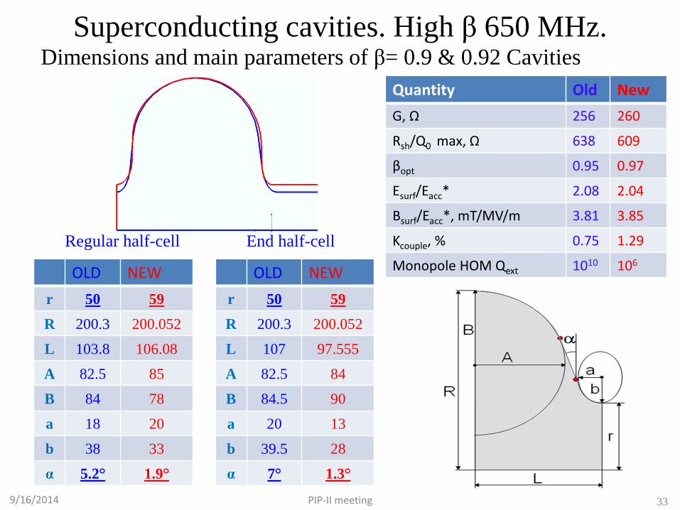
Superconducting cavities. High β 650 MHz.
Quantity Old New
G, Ω 256 260
Rsh/Q0 max, Ω 638 609
βopt 0.95 0.97
Esurf/Eacc* 2.08 2.04
Bsurf/Eacc*, mT/MV/m 3.81 3.85
Kcouple, % 0.75 1.29
Monopole HOM Qext 1010 106 OLD NEW
r 50 59
R 200.3 200.052
L 107 97.555
A 82.5 84
B 84.5 90
a 20 13
b 39.5 28
α 7° 1.3°
OLD NEW
r 50 59
R 200.3 200.052
L 103.8 106.08
A 82.5 85
B 84 78
a 18 20
b 38 33
α 5.2° 1.9°
Regular half-cell End half-cell
Dimensions and main parameters of β= 0.9 & 0.92 Cavities

34 9/16/2014 PIP-II meeting
Superconducting cavities. High β 650 MHz.
Stiffening rings located to minimize df/dP
while maintaining tunability
Blade Tuner – scaled ILC:
• High df/dP
• Insufficient tuning efficiency;
New End Tuner design:
• Low df/dP,
• Mechanical resonance s > 60 Hz;
• Good tunability;
• Less expensive.

35 9/16/2014 PIP-II meeting
Superconducting cavities. High β 650 MHz.

36 9/16/2014 PIP-II meeting
LFD Coefficient
*Leff=n*βλ/2=1.03846153846 m
Superconducting cavities. High β 650 MHz.

37 9/16/2014 PIP-II meeting
Superconducting cavities. High β 650 MHz.
df/dP vs. Tuner Stiffness
-15
-10
-5
0
5
10
15
0 20 40 60 80 100Ktuner, kN/mm
df/dP, Hz/mbar vs Tuner Stiffness
0.9 Rend=Rreg=1100.92 Rend=Rreg=1100.92 Rend=110 Rreg=120
5
6
7
8
110 115 120Rreg, mm
kN/mm
Stiffness of β=0.92 cavity kN/mm vs.
Radius of the Regular stiffening ring
- Stiffness of β=0.9 cavity
-10205080
110140170200
0 50 100Ktuner, kN/mm
df/dP, Hz/mbar vs. Tuner
Stiffness
Bellow 115mmBellow 135mmBellow 165mm
38 9/16/2014 PIP-II meeting
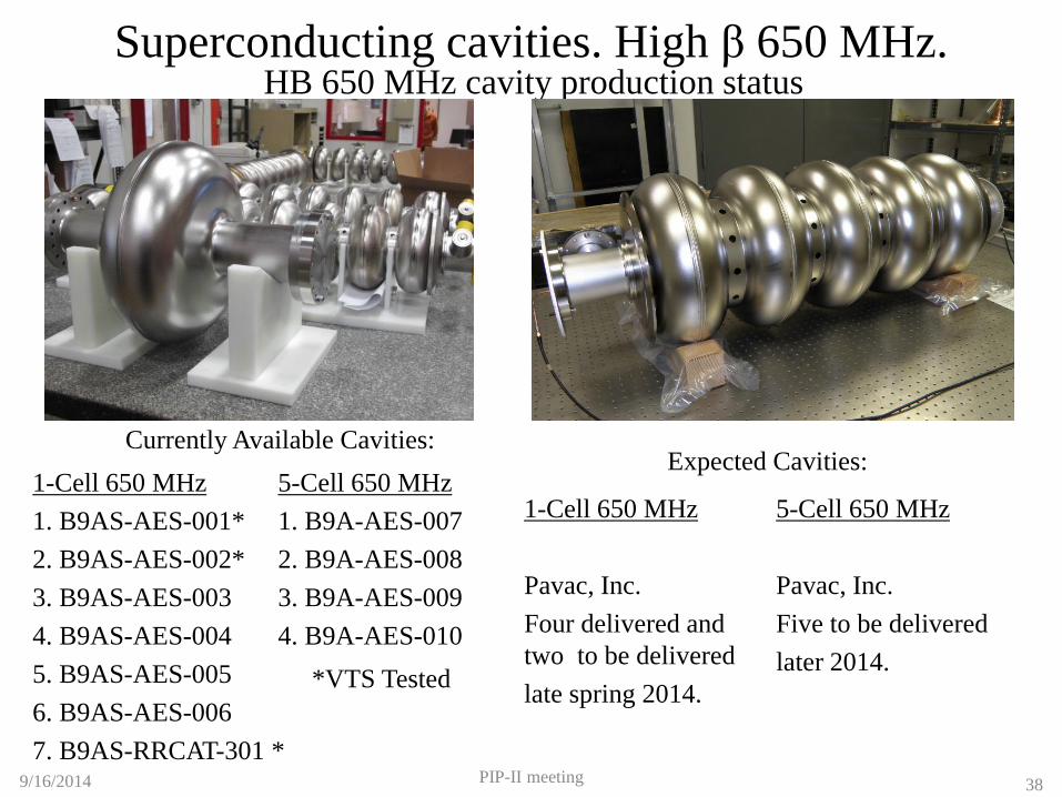
Superconducting cavities. High β 650 MHz. HB 650 MHz cavity production status
Currently Available Cavities:
1-Cell 650 MHz
1. B9AS-AES-001*
2. B9AS-AES-002*
3. B9AS-AES-003
4. B9AS-AES-004
5. B9AS-AES-005
6. B9AS-AES-006
7. B9AS-RRCAT-301 *
5-Cell 650 MHz
1. B9A-AES-007
2. B9A-AES-008
3. B9A-AES-009
4. B9A-AES-010
*VTS Tested
Expected Cavities:
1-Cell 650 MHz
Pavac, Inc.
Four delivered and
two to be delivered
late spring 2014.
5-Cell 650 MHz
Pavac, Inc.
Five to be delivered
later 2014.
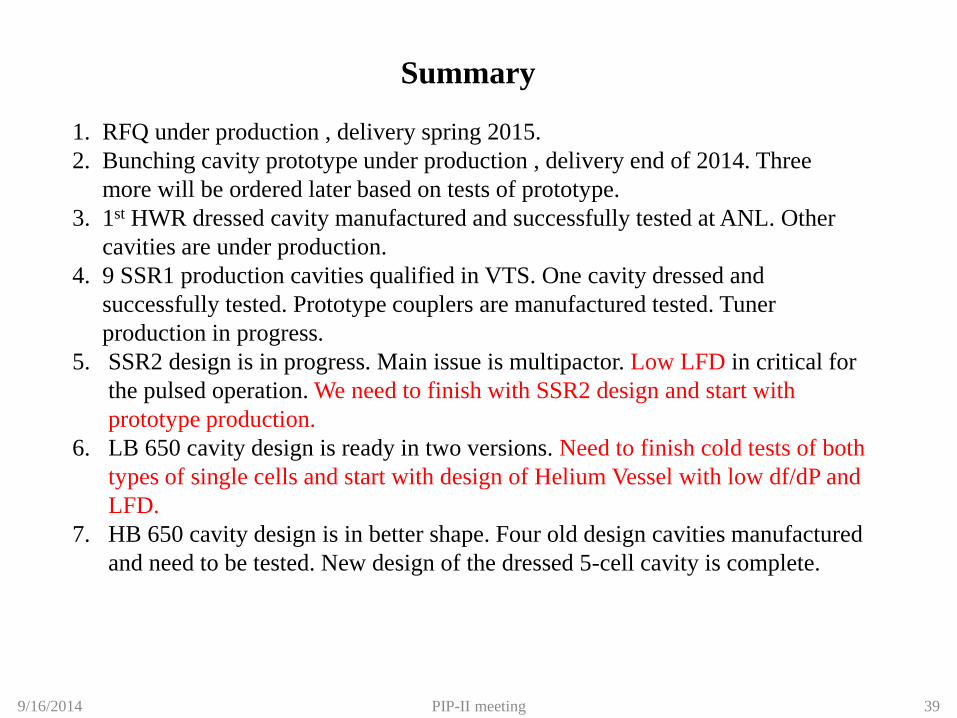
1. RFQ under production , delivery spring 2015.
2. Bunching cavity prototype under production , delivery end of 2014. Three
more will be ordered later based on tests of prototype.
3. 1st HWR dressed cavity manufactured and successfully tested at ANL. Other
cavities are under production.
4. 9 SSR1 production cavities qualified in VTS. One cavity dressed and
successfully tested. Prototype couplers are manufactured tested. Tuner
production in progress.
5. SSR2 design is in progress. Main issue is multipactor. Low LFD in critical for
the pulsed operation. We need to finish with SSR2 design and start with
prototype production.
6. LB 650 cavity design is ready in two versions. Need to finish cold tests of both
types of single cells and start with design of Helium Vessel with low df/dP and
LFD.
7. HB 650 cavity design is in better shape. Four old design cavities manufactured
and need to be tested. New design of the dressed 5-cell cavity is complete.
Summary
39 9/16/2014 PIP-II meeting