the cause of rcic shutdown in unit 3
TRANSCRIPT

Attachment 3-5-1
Attachment 3-5
The cause of RCIC shutdown in Unit 3
1. Outline of the incident and issues to be examined
Unit 3 experienced a station blackout when it was hit by tsunami on March 11th, 2011, following
the reactor scram, and while the reactor core isolation cooling (RCIC) system had been
automatically shut down due to the high reactor water level signal at 15:25 after the system had
been manually started at 15:05. Even after the tsunami, DC power sources remained available,
and water injection was continued by restarting the RCIC manually again at 16:03. But at 11:36 on
March 12th, the status indicator lamp in the main control room (MCR) confirmed the RCIC had
been automatically shut down. Operators confirmed also in the RCIC room the situation that RCIC
had been shut down and relevant valves were reset on the MCR control board for standby and
restart. But immediately after attempting the restart, the stop valve trip mechanism was unlatched,
the valve closed and the RCIC failed to restart. Although the RCIC continued to function longer
than the designed 4 hours under the station blackout conditions, the cause of the Unit 3 RCIC
shutdown was examined, based on actual plant conditions observed and design information, in
order to interpret the accident progression and to contribute to further safety enhancements by
improvements of relevant equipment and operational procedures.
2. Relevant operational actions and local situations
Table 1 shows the chronological records of relevant operational actions taken and incidents
observed until the time of the Unit 3 RCIC trip at 11:36 on March 12th and that of operational
actions for the restart.
<RCIC startup at 16:03 on March 11th, 2011>
The RCIC was automatically shut down at 15:25 on March 11th, due to a high reactor water level
signal just before the tsunami arrival. It was manually started up at 16:03, as the DC power source
was still available after the tsunami hit. Thus, the main steam relief safety valve (SRV) and RCIC
could continue controlling the reactor pressure and water level of Unit 3.
Under these circumstances, the operators configured the water injection line through both the
RCIC injection line and its test line by valve operations on the RCIC control panel. This was done
to avoid battery depletion due to RCIC startup and shutdown, and to maintain the stable reactor
water level by using the condensate storage tank (CST) as the water source. In order to ensure
moderate transition of the reactor water level, the flow rate was controlled within a predefined
range by adjusting the test line valve apertures and the flow indicator and controller (FIC). Figure 1
shows the RCIC diagram and the operational status.

Attachment 3-5-2
ReactorMO
Main steam piping
Test bypass valve
Turbine
Test line
Water source switch line
Ope
ration line
S/C
FD
W s
yste
m
Containmentvessel
Feed w
ate
r line Minimum flowbypass valve
MO
MO
MOMO
MO
MO
MOAO
MO
MO
MO
HO FIC
FT
Pump
Condensate storage tank
Turbine inlet valve
Turbine steam stop valveControl valve
Flowcontroller
MO
Containment isolation valve
Flow rate meter
PT
Suctionpressure
gauge
PT
Discharge pressure gauge
PT
PT Inlet steam pressure gauge
Exhaust pressure gauge
Condensate pump
Glands of turbine / valves
Barometric condenser
Vacuum tank
Vacuum pump
Lube oil cooler
ReactorMOMO
Main steam piping
Test bypass valve
Turbine
Test line
Water source switch line
Ope
ration line
S/C
FD
W s
yste
m
Containmentvessel
Feed w
ate
r line Minimum flowbypass valve
MOMO
MOMO
MOMOMOMOMOMO
MOMO
MOMOMO
MOMOAO
MOMO
MOMOMO
MOMOMO
HOHOHO FIC
FT
FIC
FTFT
Pump
Condensate storage tank
Turbine inlet valve
Turbine steam stop valveControl valve
Flowcontroller
MOMO
Containment isolation valve
Flow rate meter
PTPT
Suctionpressure
gauge
PTPT
Discharge pressure gauge
PTPT
PTPT Inlet steam pressure gauge
Exhaust pressure gauge
Condensate pump
Glands of turbine / valves
Barometric condenser
Vacuum tank
Vacuum pump
Lube oil cooler
Figure 1 RCIC system diagram
<RCIC shutdown at 11:36 on March 12th, 2011>
The RCIC status indicator lamp on the MCR control panel showed it had been shut down, and
the indicators showed zeros for discharged flow rate and pressure, confirming the RCIC shutdown.
Operators reset the relevant RCIC valves on the RCIC control panel for restart, and then
attempted to restart, but it was followed by immediate shutdown after the restart operations, and
then operators made an on-site check. They entered the RCIC room through the HPCI room. They
noticed that water had flooded the floor as deep as their ankles (about 10 – 20 cm) in both rooms,
but the air did not feel damp. Water drips were falling on the stop valve, etc., from the RCIC room
ceiling, but nothing abnormal was noticed on the turbine, pumps, piping, etc.
As the RCIC was confirmed locally to be out of service and no anomalies were noticed about the
mechanical structures of the steam stop valve, the operators tried again to restart the RCIC from
the MCR control panel by resetting and restarting valve operations, but the steam stop valve
closed immediately after and the RCIC shut down. While operators were struggling for
maneuvering the RCIC for status confirmation and restart actions, the high pressure core injection
system (HPCI) automatically started up due to low reactor water level signal and water injection
started again.

Attachment 3-5-3
Table 1 Chronology of RCIC operational actions and incidents observed at Unit 3
Date Time Incident observed Reference
3/11 14:47 Reactor scrammed automatically (1)
3/11 14:48 Emergency diesel generator (DG) started up automatically (1)
3/11 15:05 RCIC started up manually (1)
3/11 15:25 RCIC shut down automatically (high reactor water level signal) (1)
3/11 15:38 Station blackout (1)
3/11 16:03 RCIC started up manually
Operators configured the water injection line through both the
RCIC injection line and its test line by valve operations on the
RCIC control panel. This was done to avoid battery depletion due
to RCIC startup and shutdown, and to maintain a stable reactor
water level. In order to ensure moderate transition of the reactor
water level, the flow rate was controlled within a predefined range
by adjusting the test line valve apertures and flow indicator and
controller (FIC).
Except for essential systems required for monitoring and control,
all other non-urgent loads were disconnected to save the batteries.
Regarding monitoring instrumentations, only one channel out of
redundant channels A and B was kept connected. Emergency
lightings and clocks in the MCR were disconnected, as well as
fluorescent lights in other rooms.
(1)
3/12 11:36 RCIC shut down automatically
RCIC status indicator lamp showed “shut down.” Zeros on the
RCIC discharged flow rate and pressure indicators were
confirmed.
(1)
to
RCIC restart operations taken
Operators tried to restart the RCIC after the valve reset operations
on the RCIC control panel, which was followed by an immediate
shutdown after restart operations, and then operators were sent for
an on-site check.
The operators entered the RCIC room through the HPCI room.
They noticed water had flooded the floor as deep as their ankles
(about 10 – 20 cm) in both rooms, but the air did not feel damp.
Water drips were falling on the stop valve, etc., from the RCIC
room ceiling, but nothing abnormal was noticed on the turbine,
pumps, piping, etc.
As the RCIC was confirmed locally to be out of service and no
(1)

Attachment 3-5-4
Date Time Incident observed Reference
anomalies were noticed about the mechanical structures of the
steam stop valve, the operators tried again to restart the RCIC
from the MCR control panel by resetting and restarting valve
operations, but the steam stop valve closed immediately and the
RCIC shut down accordingly.
3/12 12:35 HPCI automatically started up due to the signal “low reactor water
level.”
(1)
(1) Fukushima Nuclear Accident Analysis Report, TEPCO, June 20, 2012
[http://www.tepco.co.jp/en/press/corp-com/release/betu12_e/images/120620e0102.pdf]
<Trip mechanism of RCIC stop valve and its resetting procedures (reference information)>
The RCIC turbine can be tripped by two different mechanisms: electrical trip and mechanical
overspeed trip. In an unusual situation, the turbine trip stop valve is closed to cut the steam flow.
Figure 2 shows a schematic diagram of the turbine steam stop valve and trip mechanisms.
A latch mechanism is built in the upper part of the valve where its stem is driven. In the electrical
trip mechanism, the trip signal (an automatic trip signal from the interlock or manual trip signal)
excites the trip solenoid and releases the latch. When unlatched, the spring in the valve cylinder
expands and the steam stop valve is fully closed.
In the mechanical trip mechanism, the tappet in the overspeed trip mechanism is pushed
upward, which works on the rod connected to the latch mechanism by spring forces, leading to the
unlatching. The electrical mechanism needs a DC power source just as the RCIC needs it for
operation and control, while the mechanical mechanism can work even if no DC power source is
available.
Latch mechanism
RCIC turbine steam stop valve
Limit switch
Trip solenoid(electricaltrip)
Motor
Mechanical turbine overspeed trip mechanism
Valve closure bylatch/unlatch mechanism
Spring
Rod
Tappet
Steam Inlet Turbine
Spring
Latch
Traveling nutCoupling
Position indicator lamp
disc
Latch mechanism
RCIC turbine steam stop valve
Limit switch
Trip solenoid(electricaltrip)
Motor
Mechanical turbine overspeed trip mechanism
Valve closure bylatch/unlatch mechanism
Spring
Rod
Tappet
Steam Inlet Turbine
Spring
Latch
Traveling nutCoupling
Position indicator lamp
disc
Figure 2 Schematics of RCIC turbine steam stop valve and its trip mechanisms

Attachment 3-5-5
Resetting of steam stop valve
In operation UnlatchedTraveling nut
rotated upward
Close turbine inlet valve
Reset steam stop valve
Open turbine inlet valve
Electrical trip
Restart RCIC
Reset
Motoropened position
Valve discrotated upward
Spring
Latch
Traveling nutCoupling
Position indicator lamp
disc
Discopened position
Motoropened position
Motoropened position
Motorclosed position
Discopened position
Discclosed position
Discclosed position
Figure 3 Schematics of RCIC turbine steam stop valve resetting
3. Conditions of DC power sources
Figure 4 shows schematics of DC power distributions and loads relevant to the RCIC and HPCI
of Unit 3. Batteries and DC power supply panels of Unit 3 were not destroyed by the tsunami,
since they had been installed in a sub-basement of the turbine building, differing from the situation
of Unit 1 and Unit 2.
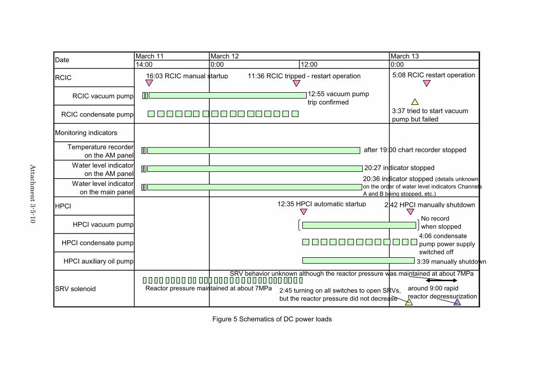
Figure 5 shows schematics of the in-service condition of DC power loads, while Table 2 gives
the chronology of incidents and power supplies for each load. DC power required by the RCIC
logic circuits and trip signals for electrical trips is supplied from the battery DC125-3A (Power
Distribution Panel 3A-1). This DC power source for the electrical trips is considered to have been
secured, when the RCIC tripped at 11:36 on March 12th, since the RCIC operation and its resetting,
and the reactor water level monitoring had been controlled in the MCR, and no evidence of
depletion of the battery DC125-3A had been noticed.
The capacity of battery DC125-3A (1200 AH in terms of a 10-hour discharge rate) was set in
consideration for the following loads: instantaneous loads such as for starting up emergency diesel
generators (DGs) upon loss of the external power source, for operating circuit breakers of power
supply panels; and standing power loads for four-hour operations of RCIC, MCR control panels,
and DC lighting devices. In reality, however, the RCIC could have been in operation for about 20
hours after the station blackout due to the tsunami had occurred. This is considered as having
been made possible because the battery could have lasted without depletion until this time for the
following reasons: having a design margin (the actual power consumption is less than the
designed value), disconnecting non-essential DC lighting devices, avoiding RCIC trips due to high
reactor water levels, etc.

Attachment 3-5-6
But from the afternoon onward of March 12th, the battery DC125-3A is considered to have been
unstable, indicating signs of depletion in vacuum pump trips, instrumentations becoming defunct,
etc.

Attach
men
t 3-5-7
Figure 4 Schematics of DC power distributions and loads relevant to HPCI of Unit 3 (1/3)
RC
IC conde
nser vacuum pum
p
DC125V battery 3A 60cells 1200AH
(10-hr discharge rate)T/B sub-basement
・・・・
T/B sub-basement 125V main bus line 3A
R/B 1st floor 125V-R/B MCC 3A
RC
IC conde
nser condensate pum
p
RC
IC turbine
steam stop valve
RC
IC control
panel (9-4)
C/B 1st floor 125V distribution panel 3A-1
・・・・
To NO.2/3 To NO.3/3
RC
IC
condensate pum
p’sisolation
valve, R
CIC
valve
position indicators
for control
valve and
steam
stop valve
etc.
Com
puter input
of H
PC
I startup signals at low
reacto r w
ater level etc.
RC
IC control
panel (9-30)
Trip channel panel
of ES
F (I) (9-78)
HP
CI control
panel(9-41)
HP
CI control
panel (9-32)
RC
IC
logiccircuits,
RC
ICturbine
control panel,
RC
ICturbine spee
d control
Reactor w
ater level instrum
entation for ES
F
(reactor water level high / low
switch [for R
CIC
and HP
CI trip
/ start or AD
S actuation])
Trip channel panel
of ES
F (I) (9-88)
Instrumentation for E
SF
(pressure / tem
perature sw
itchfor R
CIC
trip or H
PC
I isolationetc.)
HP
CI isolation logic etc.
DC125V battery 3B 60cells 1400AH
(10-hr discharge rate) T/B sub-basement
DC250V battery 3A 120cells 2000AH
(10-hr discharge rate)T/B sub-basement
ESF: Engineering safety features

Attach
men
t 3-5-8
Figure 4 Schematics of DC power distributions and loads relevant to HPCI of Unit 3 (2/3)
HP
CI condensate vacuum
pump
・・・・
T/B sub-basement 125V main BUS line 3B
R/B 1st floor 125V-R/B MCC 3B
HP
CI condenser conden
sate pump
HP
CI auxiliary oil pum
p
HP
CI control
panel (9-3)
C/B 1st floor 125V distribution panel 3B-1
・・・・
To NO.1/3
HP
CI
condensate p
ump
isolation valve,
HP
CI
valveposition indicators for controlvalve and steam
stop valveetc.
RC
ICisolation
logic circuits
HP
CI control
panel (9-39)
RC
IC control
panel (9-33)
・・・・
C/B 1st floor 125V distributionpanel 3B-2
HP
CI
logic circuits,
HP
CI
turbine trip, H
PC
I instrumentation
Trip channel panel
of ES
F (II) (9-78)
Reactor
water
levelinstrum
entation for
ES
F(reactor
water
level high
/low
sw
itch [for
RC
IC
andH
PC
I trip
/ start,
AD
Sactivation etc.])
・・・・
C/B basement 125V distribution panel 3B-4
Trip channel panel
of ES
F (II) (9-89)
DC125V battery 3A 60cells 1200AH
(10-hr discharge rate)T/B sub-basement
To NO.3/3
DC125V battery 3B 60cells 1400AH
(10-hr discharge rate) T/B sub-basement
DC250V battery 3A 120cells 2000AH
(10-hr discharge rate)T/B sub-basement
ESF: Engineering safety features
Instrumentation for E
SF
(pressure / tem
perature sw
itchfor R
CIC
trip or H
PC
I isolationetc.)

Attach
men
t 3-5-9
Figure 4 Schematics of DC power distributions and loads relevant to HPCI of Unit 3 (3/3)
RC
IC system
mortor-driven valves
(except turbine steam stop valve
)
T/B sub-basement 250V main BUS line 3A
R/B 1st floor 250V-R/B MCC 3A
・・・・
RC
IC
instrumentation
(for m
onitoring on
the
RC
IC control panel in the
MC
R)
RC
IC
instrumentation
circuit panel (9-1
9
)
C/B 1st floor Vital AC 120/240V distribution panel
T/B sub-basement 250V main BUS line 3B
・・・・ R/B 1st floor 250V-R/B MCC 3B
・・・・・・・・
Vital AC CVCF source
・・・・ Distribution panel for process computer
DC125V battery 3A 60cells 1200AH
(10-hr discharge rate)T/B sub-basement
DC125V battery 3B 60cells 1400AH
(10-hr discharge rate) T/B sub-basement
DC250V battery 3A 120cells 2000AH
(10-hr discharge rate)T/B sub-basement
To NO.2/3 To NO.1/3
Distribution panel for transient recorder
HP
CI system
mortor-driven valves
Attach
men
t 3-5-10
RCIC
RCIC vacuum pump
RCIC condensate pump
Monitoring indicators
Temperature recorderon the AM panel
Water level indicatoron the AM panel
Water level indicatoron the main panel
HPCI
HPCI vacuum pump
HPCI condensate pump
HPCI auxiliary oil pump
SRV solenoid
March 130:00
Date0:00
March 1114:00
March 1212:00
16:03 RCIC manual startup 11:36 RCIC tripped - restart operation 5:08 RCIC restart operation
3:37 tried to start vacuumpump but failed
12:55 vacuum pumptrip confirmed
after 19:00 chart recorder stopped
20:27 indicator stopped
20:36 indicator stopped (details unknownon the order of water level indicators ChannelsA and B being stopped, etc.)
No recordwhen stopped
4:06 condensatepump power supplyswitched off
3:39 manually shutdown
Reactor pressure maintained at about 7MPa
12:35 HPCI automatic startup 2:42 HPCI manually shutdown
2:45 turning on all switches to open SRVs,but the reactor pressure did not decrease
around 9:00 rapidreactor depressurization
SRV behavior unknown although the reactor pressure was maintained at about 7MPa
Figure 5 Schematics of DC power loads

Attach
men
t 3-5-11
Table 2 Chronology of incidents and power distributions to each load Battery
DC125V-3A Battery
DC125V-3B Battery
DC250V-3A Main bus line panel
Main bus line panel 3A Main bus line panel 3B 3A 3B
Date Time
Incident
MCC 3A
PDP 3A-1
PDP 3A-2
MCC 3B
PDP 3B-1
PDP 3B-2
MCC 3A
MCC3B
Vital
Remarks or presumptions (X shows the power supply
source to related load)
PDP: Power distribution panel
3/11 16:03
RCIC manual startup X X X
― Flow control by FIC while monitoring relevant parameters in MCR X
Unnecessary loads were disconnected from the vital power distribution panel except that for monitoring parameters relevant to RCIC.
RCIC automatically tripped X*1) 3/12 11:36 RCIC flow rate/discharge
pressure indicated 0 X
― RCIC resetting and restart attempted
X X
― RCIC tripped immediately after restart
X*1)
*1) No signs of DC power source depletion confirmed at this point. Voltage for electrical trip was considered to be secured.
3/12 12:35
HPCI automatic startup (low reactor water level)
X X X
to 3/12 about20:00
Monitoring indicators ・ PCV temperature chart
recorder on AM panel ・ D/W pressure, S/C
pressure and S/C water level indicators on AM panel
・ Reactor water level indicator (wide range, fuel range)
X X
As of 3/12 11:36, all indicators were working and no signs of DC power source depletion were confirmed. After 3/12 20:00, signs of DC power source depletion were noticed such as out-of-service indicators. DC power did not seem to have been stable.

Attachment 3-5-12
4. Examination of the cause of repeated shutdown
4.1 Possibility of electrical trips
It is highly possible that the RCIC was not tripped by mechanical overspeed, but electrically at
11:36 on March 12th, as seen in the afore-mentioned monitoring and operating situations in MCR
and field observations, based on the following grounds.
The turbine steam stop valve equipped with the trip mechanisms had been closed, tripping
the RCIC;
The operational procedures of turbine steam stop valve had been completed to the
resetting procedure from the MCR panel; and
DC power for RCIC operation and control had been available.
Figure 6 shows the interlock logic of RCIC electrical trips.
Figure 6 The interlock logic of RCIC electrical trips
The following subsections describe the feasibility conditions of each interlock logic, among
which the highest likelihood is for high turbine exhaust pressure.
Manual trip button
High reactor water level (L-8;5655mm above TAF)
High turbine exhaust pressure (0.29MPa[gage])
Low pump suction pressure (-0.0508MPa[gage])
Turbine trip (Steam stop valve
closed)
RCIC automatic isolation signal isolates the
RCIC by detecting steam leakage or exhaust
rupture disk damage.
Turbine overspeed (electrical trip: rated×110% rpm)
OR
OR
High RCIC turbine pump room temperature (93℃)
High flow rate in steam piping (±120.7kPa)
Low steam supply pressure (0.344MPa)
High pressure between the turbine exhaust rupture diaphragms
(69kPa)
OR
RCIC automatic isolation signal

Attachment 3-5-13
4.2 Possibility of high turbine exhaust pressure interlock working
Figure 7 shows the RCIC turbine exhaust pressure changes observed by the operators. Due to
loss of heat removal functions, the exhaust pressure was increasing with the increase in both the
D/W and S/C pressures, and as of 11:36 on March 12th, when the RCIC tripped, they were at a
level very close to the preset high exhaust pressure trip level. The exhaust pressure reading was
0.25MPa[gage] as of 11:25 on March 12th, and had not reached the preset trip level
(0.29MPa[gage]). Further, there is no record on the exhaust pressure at the very instant of the
RCIC trip, and so no direct evidence of observation exists concerning the RCIC trip due to high
exhaust pressure.
0.0
0.1
0.2
0.3
0.4
3/1118:00
3/1121:00
3/120:00
3/123:00
3/126:00
3/129:00
3/1212:00
3/1215:00
3/1218:00
Exh
aust
pre
ssur
e (M
Pa[
gage
])
0.101
0.201
0.301
0.401
0.501
PC
V p
ress
ure (
MP
a[ab
s])
RCIC exhaust pressure(measured)HPCI exhaust pressure(measured)D/W pressure(measured)S/C pressure(measured)
Figure 7 RCIC exhaust pressure change and PCV pressure change
It should be noted, however, that the D/W and S/C pressures showed an increasing trend again,
after remaining stable at one level for almost 3 hours before the RCIC trip, in the particular
circumstance in which the PCV pressure should have simply increased under the situation of no
final heat sink. Consequently, it is possible to consider that the turbine exhaust pressure reached
the trip level at 11:36 on March 12th, based on the following.
(1) Instrumentation accuracies
As is shown in Figure 8, exhaust pressure gauges for the MCR indicator and the logic circuit
input are different, and about 0.02MPa difference could exist in these two instrumentations due to
instrumentation accuracies and reading errors. Even taking these inaccuracies into account, the
3/12 11:36RCIC trip
3/12 12:35 HPCI automatic startup
RCIC exhaust pressure Trip setpoint 0.29MPa[gage]
S/C spray ON
3/12 11:25Exhaust pressure
reading 0.25MPa[gage]

Attachment 3-5-14
pressure reading of 0.25MPa[gage] at 11:25 on March 12th is considered not to have reached the
trip level (0.29MPa[gage]).
S/C
MO
MO
HO
Turbine inlet valve
Turbine steam stop valve
Control valve
PT
PT
MCR display
Input tologic circuit
About ±0.02MPa differences can exist when indicator and reading accuracies are considered
Condensatepump
Glands of turbine or valves
Barometriccondenser
Vacuumtank
Vacuumpump
S/C
MOMOMO
MOMOMO
HOHOHO
Turbine inlet valve
Turbine steam stop valve
Control valve
PTPT
PTPT
MCR display
Input tologic circuit
About ±0.02MPa differences can exist when indicator and reading accuracies are considered
Condensatepump
Glands of turbine or valves
Barometriccondenser
Vacuumtank
Vacuumpump
Figure 8 Positional illustration of RCIC exhaust pressure gauges
In the meantime, the D/W and S/C pressures increased from 11:25 through 11:36. According to
the RCIC test operation that had been done during the scheduled maintenance, the turbine
exhaust pressure under the reactor rated power condition (about 6.9MPa[gage]) was about
0.05MPa when the S/C pressure was atmospheric pressure. This represents the pressure loss in
the turbine exhaust piping under rated power operation. The S/C pressure measured from 11:25
through 11:36 was about 0.36MPa[abs], and when 0.05MPa is added as the pressure loss, it
reaches 0.41MPa[abs] (about 0.31MPa[gage]), exceeding the trip level.
It is considered, therefore, the turbine exhaust pressure might have reached the trip level when
the D/W and S/C pressures increased from 11:25 through 11:36, although the exhaust pressure, at
11:25 on March 12th had not reached the trip level, but was close to it (0.29MPa[gage]).
(2) Explanation of the successful RCIC turbine resetting operation
As was shown in Figure 7, the turbine exhaust pressure reading was about 0MPa[gage] after
the RCIC trip at 11:36 on March 12th. This is because the steam in the exhaust piping was
condensed and because the S/C pressure (back pressure) was blocked by the check valve in the
downstream side of the exhaust piping.
Concerning the incident of repeated trips of the RCIC upon steam injection in restarting attempts
after successful resetting, it can be interpreted by the following scenario: If a trip is triggered by the
high turbine exhaust pressure, the exhaust pressure on the indicator decreases, the trip condition
is cleared once, and later upon steam injection the RCIC trips again due to the increased
pressure.

Attachment 3-5-15
On the other hand, the scenario is still unclear concerning the incident of D/W and S/C pressure
changes, i.e., monotonously increasing upon loss of heat removal functions with no final heat sink,
then staying once at a level from 09:30 through 11:25 on March 12th, and again starting to increase.
At that time, the reactor steam was being released to the S/C via the SRV and RCIC, and the
water inside the S/C was likely to have thermally stratified. The incident might have been caused
by some unknown phenomena in the S/C.
4.3 Possibility of other interlocks working
Other interlock conditions are unlikely to be met, as discussed below.
<Manual trip>
No traces of this were confirmed, which indicates the manual scram button had been pushed.
<High reactor water level (L-8: TAF+5655mm)>
Figure 9 shows the chart record of reactor water level (narrow range) and Figure 10 shows the
measured water level changes which operators read in the indicators. The RCIC flow rate was
being controlled by the FIC while monitoring the reactor water level, and as of 11:36 on March 12th,
when the RCIC tripped, the reactor water level had not reached the level L-8. An RCIC trip due to
high reactor water level interlock is not possible.
<Low pump suction pressure (-0.0508MPa[gage])>
This could occur if the condensate storage tank water level decreased. But immediately after,
the HPCI could have been started up and its operation continued (using the same trip signals).
Further, if the tank water level really dropped below the preset trip level, the RCIC resetting
operation would not have been successful. These are inconsistent with the facts as they are
known.
<High turbine overspeed (electrical trip: rated x 110% rpm)>
It is unlikely that the overspeed trip occurred, since the DC power for RCIC control was available,
and the steam control valve was functional while the operator was monitoring the reactor water
level and controlling RCIC flow rate using FIC.
<Automatic isolation signal>
No records exist showing the status indicator lamp indicated the RCIC isolation valve closure.
Further, the PCV isolation valve on the outer side was closed from the MCR at around 11:00 on
March 13th.

Attachment 3-5-16
Red: Reactor water level (narrow range)
Green: Reactor pressure (wide range)
Figure 9 Chart record of reactor water level/pressure
-10
-8
-6
-4
-2
0
2
4
6
8
10
3/1118:00
3/120:00
3/126:00
3/1212:00
3/1218:00
3/130:00
3/136:00
3/1312:00
Rea
ctor
wat
er le
vel (
m)
Wide range water level(measured)
Fuel range water level(measured)
Figure 10 Reactor water level changes
5. Related countermeasures
In the development of tsunami accident management procedures under station blackout
conditions for the Kashiwazaki-Kariwa Nuclear Power Station, a procedure to bypass the high
RCIC turbine exhaust pressure interlock is being developed to continue water injection using the
RCIC even when the S/C pressure increases. This is based on a concept to prioritize continuing
the RCIC operation for flexibility even if the turbine exhaust pressure exceeds the trip level, since
such an operation will not damage the RCIC equipment immediately.
The RCIC exhaust piping has a vent line equipped with a rupture disc for preventing
3/12 11:36RCIC tripped
3/12 12:35 HPCI automatic startup
3/13 2:42 HPCI manual shutdown
3/12
12:
00
3/13
00:
00
L8 setpoint
3/12 11:36 RCIC tripped
L8 setpoint
TAF
BAF

Attachment 3-5-17
overpressurization. This is because the RCIC is designed so that its pressure is released when the
RCIC rupture disc physically ruptures, if the RCIC turbine exhaust pressure continues to increase
as the S/C pressure increases, and reaches the rupture disc working pressure. Practically,
however, the S/C pressure is controlled, since the PCV is cooled by means of the PCV spray or
PCV venting by alternative water injection lines (the pressure limit for PCV venting is set lower
than the RCIC rupture disc working pressure).
There are other countermeasures, too, for strengthening high pressure water injection functions,
and some examples are listed below.
Reinforced DC power source (capacity intensification, elevated positioning).
Additional installation of a high pressure alternative cooling system (HPAC).
Development of local RCIC manual startup operating procedures upon loss of all AC and
DC power sources.
6. Summary
It is highly possible that the RCIC was not tripped by mechanical overspeed, but was electrically
tripped at 11:36 on March 12th, based on analysis of the monitoring and operating situations in the
MCR and field observations, for the following reasons.
The turbine steam stop valve, equipped with trip mechanisms, had been closed, tripping
the RCIC.
The operational procedure of the turbine steam stop valve had been completed to the
resetting procedure from MCR panel.
DC power for RCIC operation and control had been available.
Among possible interlock conditions for electrical trips, the one with the highest likelihood was
for the high turbine exhaust pressure. As of 11:25 on March 12th, the turbine exhaust pressure
reading was 0.25MPa[gage], and below the preset trip level (0.29MPa[gage]). But the D/W
pressure and S/C pressure were increasing after remaining stable at one level before the RCIC
trip, and it was possible, from the following, that the turbine exhaust pressure reached the trip level
at 11:36 on March 12th, the time of RCIC trip.
When the pressure loss in the RCIC exhaust piping was added to the S/C pressure reading,
the turbine exhaust pressure would be at the level exceeding the trip level. Therefore, the
turbine exhaust pressure had to be close to the trip level.
It was possible that the turbine exhaust pressure reached the trip level when the S/C
pressure increased from 11:25 through 11:36 on March 12th.
It was possible to interpret the incident development as that the RCIC resetting could be
done (the trip condition was cleared once), but it tripped immediately afterward upon steam
release again.

Attachment 3-5-18
Other interlock conditions were unlikely to be met.
(End)