the canopy camera - us forest service · to meet the requirements of the canopy camera is...
TRANSCRIPT

This file was created by scanning the printed publication.Errors identified by the software have been corrected;
however, some errors may remain.

Station Paper No. 72 October 1962
THE CANOPY CAMERA
by
Harry E. Brown, Research Forester
Rocky Mountain Forest and Range Experiment Station1
Central headquarters maintained in cooperation with Colorado State University, Fort Collins. Author is stationed at Flagstaff, in cooperation with Arizona State College.
CONTENTS
Introduction
Other devices for overhead photography
Optical system of the canopy camera
Construction
Materials and specifications
Box assembly Film assembly Shutter assembly Optical assembly Mounting assembly
Construction procedure
Box assembly Film assembly Shutter assembly Optical assembly
Pinhole Lenses Alignment
Preparation of grids
Operation
Setup Exposure Film Filters Stereo photography
Summary
Literature cited
z
z
z
z 3 3 4 4
5
5 7 7
13
13 13 14
14
15
15 18 zo zo zo
zo
zz

THE CANOPY CAMERA
by
Harry E. Brown, Research Forester
INTRODUCTION
The canopy camera is a device of new design that takes wide-angle, overhead photographs of vegetation canopies, cloud cover, topographic horizons, and similar subjects. Since the entire hemisphere is photographed in a single exposure, the resulting photograph is circular, with the horizon forming the perimeter and the zenith the center.
Photographs of this type provide a means of studying the relationships between canopy coverage and such things as precipitation interception, wind, evaporation, radiation, temperature, tree growth, and forage production. Coverage and distribution of the canopy are put in quantitative terms with the help of grids, which are placed over the photos.
A noteworthy feature of the camera is its optical system, which uses two lenses in conjunction with a pinhole. Another feature is the low cost--approximately $60 for materials in 1960. The camera is not difficult to build, and the job can be done by a careful worker without special tools or experience.
This paper provides the information necessary for others to build and operate the canopy came:;:-a. Because field studies with the camera are incomplete at this time, there will be minimal treatment of interpretive phases of canopy"photography.
OTHER DEVICES FOR OVERHEAD PHOTOGRAPHY
Probably the most common method for obtaining wide -angle photographs of overhead subjects is with a conventional camera aimed from above at a convex mirror (Cialdea 1956). This system has the advantage of simplicity and good image quality, but the camera obstructs part of the field of view, a decided disadvantage.
Other systems involve special cameras with an extra-wide field of view. The simplest of these is a pinhole camera with a very short focal length, of the type developed by Ashton Codd (1959). Codd 1s camera had a 1-1/8 inch focal distance and a 90° field of view. A modification of this camera by the Pacific
- 1 -

Southwest Forest and Range Experiment Station increased the field to about 160° by shortening the focal distance to 0. 315 inch (Clark 1961).
These inexpensive pinhole systems have an infinite depth of field, but because of their short focal distance they produce photographs with a wide range of scale and exposure. They also lack the high resolution of detail that can be achieved by lens cameras. Lubschez (1935) has published a worth-while description of pinhole photography, including details of pinhole construction. Wood (1934) describes another type of pinhole camera called the 11fisheye, 11
which passes light rays through a pinhole and a box of water to obtain a wide angle.
Extreme wide -angle photographs of excellent quality are obtained by using cameras with special combinations of lenses. Such a system is used in the Robin Hill camera, which takes 180° photographs by means of a lens that contracts the incident angle of light to about 90° before it is transmitted through the photographic lens (Anonymous). This camera was used in a comprehensive application of canopy photography by Evans and Coombe (1959).
Another special camera, with a panorama -lens of 154° aperture, was used for sky photography by Dirmhirn ( 1958 ).
OPTICAL SYSTEM OF THE CANOPY CAMERA
The canopy camera is made with both a pinhole and lenses in an attempt to combine the advantages of both systems.
Two thin, diverging lenses are cemented to the outer face of a shutter housing; the pinhole is attached inside the housing, immediately above the iris and shutter elements. Spacing of the lenses, pinhole, and film plane are such that a 3. 6-inch circular image of the entire hemisphere is produced at the film plane on 4x5 film. Scale and exposure are reasonably uniform across the photo.
Light enters the convex outer lens from a 180° angle of view (fig. 1 ). It is then contracted by the two lenses to an angle of about 108°, which is well within the capabilities of a pinhole system. Rays entering the pinhole at this angle form an image of the prescribed size at a distance 1. 34 inches behind the pinhole.
CONSTRUCTION
MATERIALS AND SPECIFICATIONS
Lid (African mahogany)
Sides (African mahogany)
Box Assembly
1 pc. 4 pc.
2 pc. 2 pc.
- 2 -
Finish dimensions (Inches)
7-7/16 X 7-7/16 X 3/4 8-15/16 X 1-3/16 X 3/4
8-1/4 X 3-7/8 X 3/4 8-15/16 X 3-7/8 X 3/4
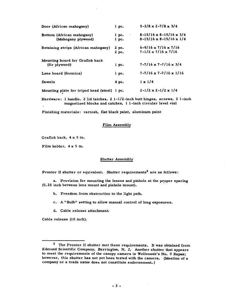
Door (African mahogany) 1 pc. 5-3/8 X Z-7/8 X 3/4
Bottom (African mahogany) 1 pc. 8-15/16 X 8-15/16 X 3/4 (Mahogany plywood) 1 pc. 8-15/16 X 8-15/16 X 1/4
Retaining strips (African mahogany) Z pc. 6-9/16 X 7/16 X 7/16 Z pc. 7-1/Z X 7/16 X 7/16
Mounting board for Graflok back (fir plywood) 1 pc. 7-7/16 X 7-7/16 X 3/4
Lens board (formica) 1 pc. 7-7/16 X 7-7/16 X 1/16
Dowels 4 pc. 1 X 1/4
Mounting plate for tripod head (steel) 1 pc • Z-1/ZxZ-1/Zx 1/4 •
Hardware: 1 handle, Z lid latches, Z 1-1/Z -inch butt hinges, screws, Z l-inch magnetized blocks and catches, 1 l-inch circular level vial
Finishing materials: varnish, fiat black paint, aluminum paint
Film Assembly
Grafiok back, 4 x 5 in.
Film holder, 4 x 5 in.
Shutter Assembly
Prontor n shutter or equivalent. Shutter requirements2 are as follows:
a. Provision for mounting the lenses and pinhole at the pr.oper spacing (0. 1.6 inch between lens mount and pinhole mount).
b. Freedom from obstruction to the light path.
c. A "Bulb" setting to allow manual control of long exposures.
d. Cable release attachment.
Cable release (1 0 inch).
2 The Prontor II shutter met these requirements. It was obtained from Edmund Scientific Company, Barrington, N. J. Another shutter that appears to meet the requirements of the canopy camera is Wollensak's No. 0 Rapax; however, this shutter has not yet been tested with the camera. (Mention of a company or a trade name doeb not constitute endorsement. )
- 3 -
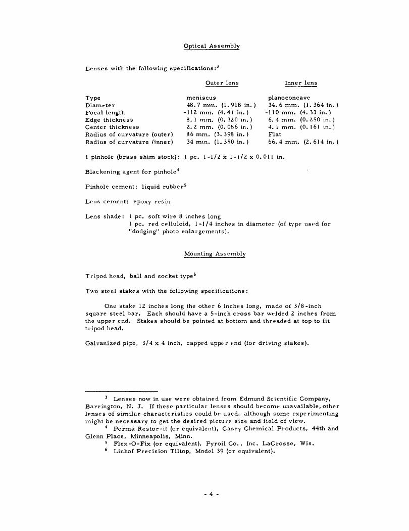
Optical Assembly
Lenses with the following specifications : 3
Type Diamt""ter Focal length Edge thickness Center thickness Radius of curvature (outer) Radius of curvature (inner)
Outer lens
meniscus 48. 7 m tn. ( 1. 9 18 in. )
-112 mm. (4. 41 in.) 8. 1 mm. (0. 320 in.) z. 2 mm. (0. 086 in.) 86 mm. (3. 398 in.) 34 mtn. (1. 350 in.)
Inner lens
planoconcave 34. 6 mm. ( 1. 364 in. )
-110 mm. (4. 33 in.) 6. 4 mm. (0. 250 in.) 4. 1 mm. (0. 161 in. ) Flat 66.4 mtn. (2. 614 in.)
1 pinhole (brass shim stock): 1 pc. 1-1/2 x 1-1/2 x 0. 011 in.
Blackening agent for pinhole 4
Pinhole cement: liquid rubber 5
Lens cement: epoxy resin
Lens shade: 1 pc. soft wire 8 inches long 1 pc. red celluloid, 1-1 I 4 inches in diameter (of type used for "dodging" photo enlargements).
Mounting Assembly
Tripod head, ball and socket type 6
T\\·o steel stakes with the following specifications:
One stake 12 inches long the other 6 inches long, made of 3/8-inch square steel bar. Each should have a 5-inch cross bar welde;>d 2 inches from the upper end. Stakes should be pointed at bottom and threaded at top to fit tripod head.
Galvanized pipe, 3/4 x 4 inch, capped upper l'nd (for driving stakes).
3 Lenses now in use were obtained from Edmund Scientific Company, Barrington, N. J. If these particular lenses should become unavailable, other lt>nses of similar characteristics could bP used, although some experimenting might be necessary to get the desired picturC' size and field of view.
4 Perma Restor -it (or equivalent), Casey Chemical Products, 44th and Glenn Place, Minneapolis, Minn.
5 Flex-0-Fix (or equivalent), Pyroil Co., Inc. LaCrosse, Wis. Linhof Precision Tiltop, Model 39 (or equivalent).
- 4 -

Path
Figure 1. --Optical system of the canopy camera, scale 2: 1. Ray paths from the maximum angle of view are shown as they pass through the lenses and pinhole to the film. Note that the upper edge of the camera box provides the cutoff for the viewing angle. Ray -tracing was done by James Gibson, who used methods described by Conrady (1957 ).
CONSTRUCTION PROCEDURE
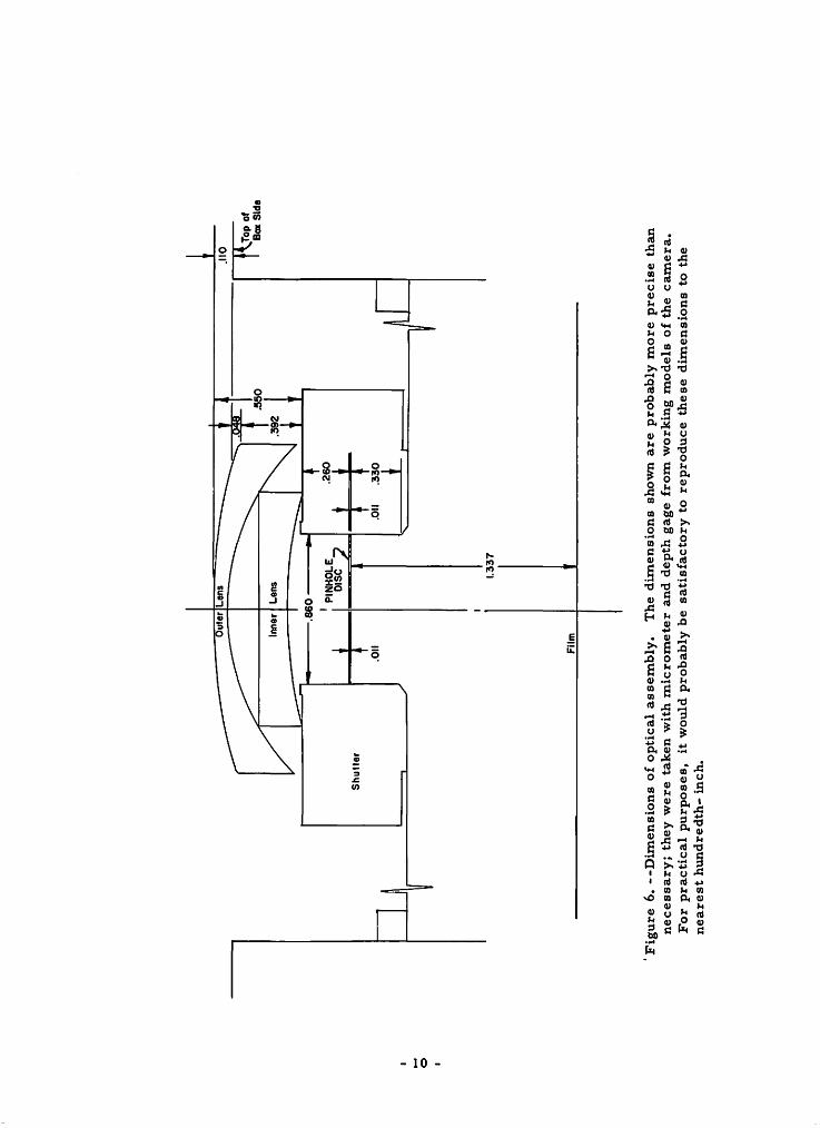
Five drawings have been prepared to aid in camera construction. The isometric drawing (fig. 2) shows the general appearance and outside dimensions of the camera, the exploded diagram (fig. 3) shows arrangement of the various components, the top and cross-section drawings (figs. 4, 5) show interior features and placement, and critical dimensions of the optical assembly are shown in figure 6. These dimensions are more for descriptive than instructional purposes, since the proper dimensions should be fairly well achieved if all other directions are followed.
Box Assembly
The box assembly can be built with standard woodworking tools, and fastened with mortised and glued joints. It includes sides, mounting boards for lens and camera back, hinged door, bottom, and lid.
After the sides are assembled, the mounting board is cut to size, bored, and glued to the lens board (fig. 7). The unit is fastened into the box with wooden strips rather than mortised joints, so that it can be removed if necessary.
- 5 -
:·· . ·.Upper Eqe Of · Ccimer~ Box
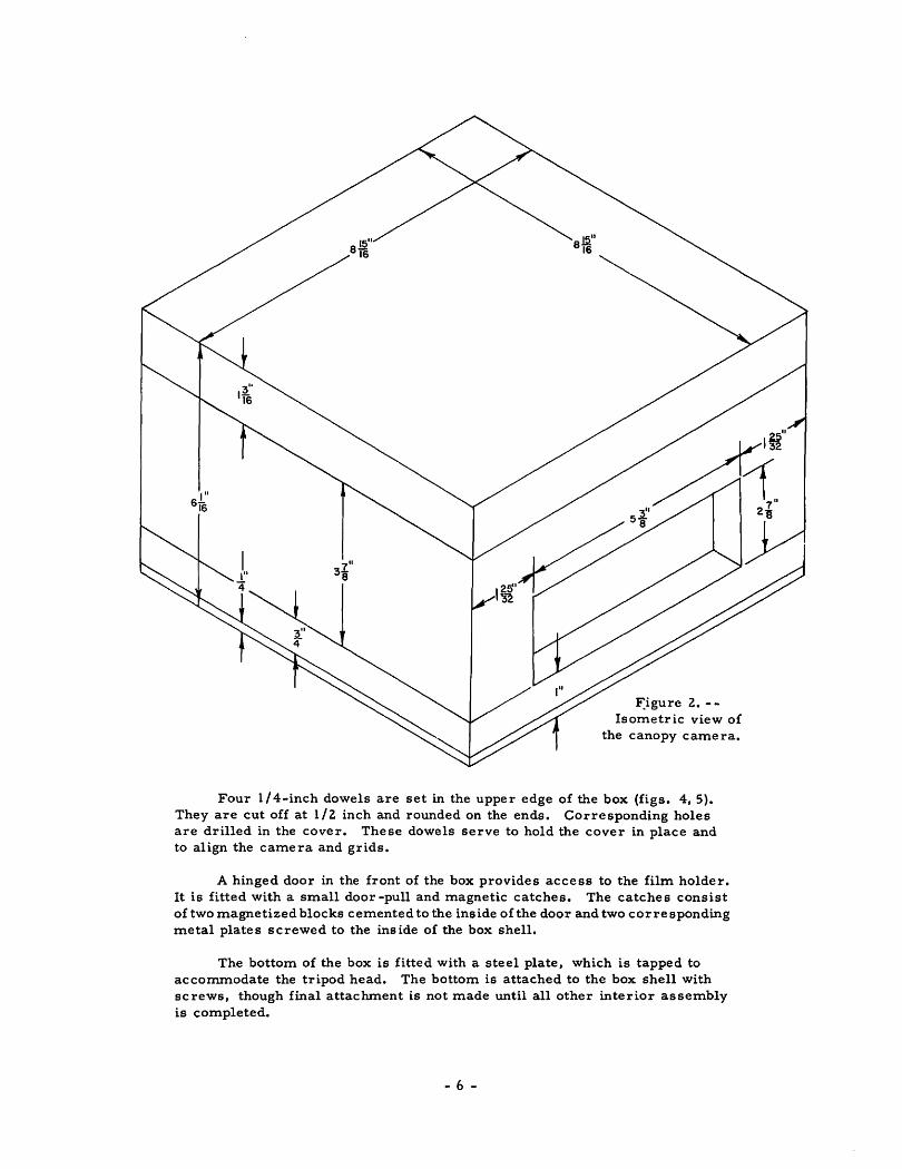
F:igure Z. -Isometric view of
the canopy camera.
Four 1/4-inch dowels are set in the upper edge of the box (figs. 4, 5). They are cut off at 1 /Z inch and rounded on the ends. Corresponding holes are drilled in the cover. These dowels serve to hold the cover in place and to align the camera and grids.
A hinged door in the front of the box provides access to the film holder. It is fitted with a small door -pull and magnetic catches. The catches consist of two magnetized blocks cemented to the inside of the door and two corresponding metal plates screwed to the inside of the box shell.
The bottom of the box is fitted with a steel plate, which is tapped to accommodate the tripod head. The bottom is attached to the box shell with screws, though final attachment is not made until all other interior assembly is completed.
- 6 -
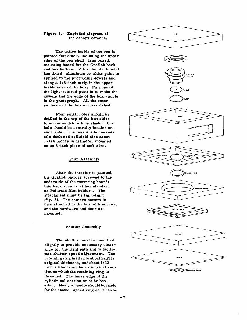
Figure 3. --Exploded diagram of the canopy camera.
The entire ins ide of the box is painted flat black, including the upper edge of the box s·hell, lens board, mounting board for the Graflok back, and box bottom. After the black paint has dried, aluminwn or white paint is applied to the protruding dowels and along a 1/8-inch strip in the upper inside edge of the box. Purpose of the light-colored paint is to make the dowels and the edge of the box visible in the photograph. All the outer surfaces of the box are varnished.
Four small holes should be drilled in the top of the box sides to accommodate a lens shade. One hole should be centrally located on each side. The lens shade consists of a dark red celluloid disc about 1-1/4 inches in diameter mounted on an 8 -inch piece of soft wire.
Film Assembly
After the interior is painted, the Graflok back is screwed to the underside of the mounting board; this back accepts either standard or Polaroid film holders. The attachment must be light-tight (fig. 8 ). The camera bottom is then attached to the box with screws, and the hardware and door are mounted.
Shutter Assembly
The shutter must be modified slightly to provide necessary clearance for the light path and to facilitate shutter speed adjustment. The retaining ring is filed to about half its original thiclmess, and about 1/31. inch is filed from the cylindrical section on which the retaini.Jlg ring is threaded. The inner edge of the cylindrical section must be bevelled. Next, a handle should be made for the shutter speed ring so it can be
~SHUTTER ~~SING
O·•LTER
c- -------
- 7

A I
I I I
I
\ \
I
\ \
/
/ /
/
.,...#~'---/,
--
TOP VIEW
/ ,/"
........
I I I I
I I
I
~ I
// BOX SIDES (4)---t--+---
CIRCULAR LEVEL VIAL
SCALE0C: =---==::ill"-----
2"
Figure 4. --Top view of the canopy camera. This view shows the camera as it would appear with the lid off, prior to mounting the shutter and lenses. At the front of the camera (bottom of figure) are dotted lines indicating the door opening and the metal strips used as door catches. The lines through the retaining strips indicate location of horizontal screws (see also fig. 5 for location of retaining strips).
turned after the lenses are attached. The handle consists simply of a flat projection of plastic metal compound carefully buUt up to about 1/4 inch on the knurled edge of the ring (fig. 5, view A-A).
The shutter is placed in the hole in the lens board, and the retaining ring on the underside is tightened as much as possible. To be sure the shutter
- 8 -
A
won't twist on the lens board, a coating of cement or liquid rubber should be applied to the retaining ring. If the shutter loosens during use it should be carefully re-cemented in place. Under ordinary circumstances it should not be necessary to make a new grid.
I I
I I I I I
I I I t---, r--- -- -----, r--i
I I I I I I
~=J== ============:!:=~ ""?~"=====;== ===== ===:!:.::::: ::ol I '----r----' ----.;...~---4---~------,"" 1 I 1
1 :
I I L ____________ j ___________________ L ___________ ~
DOOR OPENING
I
I~ r.\ I FRONT VIEW
I I I I I
I
J
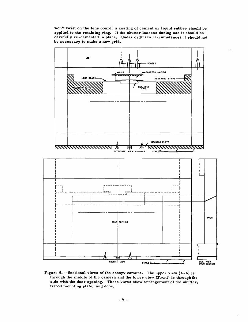
Figure 5. --Sectional views of the canopy camera. The upper view (A-A) is through the middle of the camera and the lower view (Front) is through the side with the door opening. These views show arrangement of the shutter, tripod mounting plate, and door.
- 9 -
DOOR
SlOE VIEW OOOfl SECTION
.... 0
.Oil
1.33
7
Film
.110
Top
of
Box
Sld
e
'Fig
ure
6.
--D
imen
sio
ns
of
op
tical
ass
em
bly
. T
he
dim
en
sio
ns
sho
wn
are
pro
bab
ly m
ore
pre
cis
e t
han
n
ecess
ary
; th
ey
were
tak
en
wit
h m
icro
mete
r an
d d
ep
th g
age
fro
m w
ork
ing
mo
dels
of
the
cam
era
. F
or
pra
cti
cal
pu
rpo
ses,
it
wo
uld
pro
bab
ly b
e sa
tisf
acto
ry t
o r
ep
rod
uce t
hese
dim
en
sio
ns
to t
he
neare
st
hu
nd
red
th-
inch
.

Figure 7. --Lens board and back board glued together and ready for mounting in the box. View is from the underside. The shutter is attached to the upper side and the Graflok back to the underside .
- 11 -
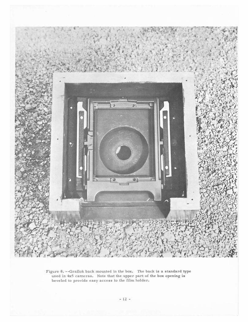
Figure 8. --Graflok b k us d . ac mounted in the box Th e m 4x5 cameras. Note th • e back is a standard t beveled to provide easy acces:\:t~:pf~lerp hart of the box opening i sy p e
l m older.
- 1 z -

Optical Assembly
Pinhole
A good pinhole is an absolute necessity in the canopy camera. The important features of the pinhole are: (1) a clean, circular hole; (2.) a small hole; (3) very thin edges; and (4) a non-reflective surface in the vicinity ofthe hole. The smaller the hole, the sharper the image; however, a hole that is too small is susceptible to clogging and necessitates long exposures.
The pinhole is made in 0. 011-inch brass shim stock. The stock is first cut into a 1-1/2.-inch square; then a dimple is made with a 1/4-inch steel ball-bearing, which is placed on the stock and tapped lightly with a hammer. The stock is then turned over and the bottom side of the dimple filed until it is very thin (about 0. 002. inch). This thickness is reached when a "dimple in the dimple 11 barely begins to form on the upper side. Any further filing will make the section so thin it will tear.
The pinhole is started by pricking the dimple from the top with a No. 12. needle. After the needle has made a tiny hole, the square is turned over and the burr on the bottom is sanded off with 6/0 A garnet paper. The needle is inserted again from the top, a little farther this time, and the bottom sanded. This is continued until the needle can be inserted about 3/64 inch into the top of the square. The depth of the penetration can be controlled by blackening 3/64 inch of tht needle tip with a chemical such as Perma Restor-it, and inserting the needle only to the depth of the blackening. When the proper pinhole size is achieved, the needle should be inserted in each side alternately andtwirled to ream it out. The hole should then be examined under a microscope to be sure it is the proper size and perfectly round, and free of burrs and any foreign material. Pinholes made this way have a diameter of about 0. 007 inch.
The square is next cut into a disc 0. 84 inch in diameter, with the hole exactly at the center. This is the interior diameter of the barrel in a Prontor shutter. The disc is then blackened by dipping in Perma Restor -it. It is important that a chemical be used for this purpose rather than any type of surface coating, because the latter will clog the pinhole.
The last step before attaching the pinhole is to examine the orifice through a microscope again to be sure it is clean and perfect. Then the pinhole disc is cemented to the shoulder inside the barrel of the shutter, with liquid rubber (see figs. 1 and 4 for pinhole location).
Even if only one camera is being made, the builder should make several pinholes. Pinhole -making is a skill that requires practice, and the first few attempts are likely to be unsatisfactory.
Lenses
With the shutter and pinhole installed, the next step is to mount the lenses. The two lenses are first cemented together; the larger lens is positioned directly to the top of the smaller one and exactly on center. One way to obtain proper alignment is to draw two concentric circles on a piece of paper, with exact
- 13 -

diameters of the two lenses. The smaller lens is placed on its circle and tacked with a little glue; then cement is applied around its upper edge (a 1/16-inch strip is adequate). The larger lens is then placed carefully on top, care being taken to align it with the larger circle. After the between-lens cement has dried, the lenses are carefully centered and cemented to the top surface of the shutter.
Epoxy resin is satisfactory for the lens cementing job. If only a small quantity is used for the between-lens joint, there will be no interference with incoming light rays. Because there is no face -to -face lens contact it is not necessary to use balsam or other special lens cements.
Alignment
A line -of-sight across the top of the box shell should intercept the outer lens at about 0. 05 inch above the upper corner of the top lens (see fig. 1 ). In this position the lens can take in light from the entire 180° hemisphere, and a natural cutoff at 180° is provided by the upper edge of the box shell.
The horizontal alignment of lens and box edge can be tested by placing the camera on a level floor and photographing two marked boards placed nearly in line 5 feet and 10 feet away from the camera. In the photograph, the edge of the box should cut off the picture at a height on both boards equal to the height of the box.
PREPARATION OF GRIDS
Interpretation of canopy photographs can be greatly facilitated by the use of grids. At its simplest, such interpretation involves placing a transparent grid over the photograph and estimating percent canopy coverage in each grid compartment.
Two grids are illustrated in this paper (figs. 9 and 1 0). One of these is an equal-area type (with areas equal but shapes different); the other is a spherical coordinate type involving four parallels of latitude or "altitude" as they will be called.
To make these grids, a photograph was taken of an arrangement of marks made at measured altitudes on the walls and ceiling of a room; these altitude marks constituted the radii of grid circles, which were reproduced on transparent material and used as overlays on subsequent photographs.
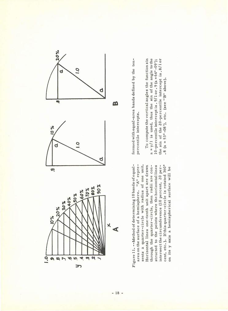
The grid marks were located with a transit, which was set up and carefully leveled in the center of a room. With the help of a plumb bob a mark was made on the ceiling directly over the center of the transit, and the distance from the ceiling to the horizontal axis of the telescope was measured. Marks were then made on the walls at vertical angles corresponding with 10 percentile portions of the hemisphere. The method of computing the vertical angles is shown in figure 11. The angles used were as follows:
- 14 -

Percent of Sin of the
the hemisphere vertical angle Vertical angle
100 o.oo 0°00 1
90 • 10 5•44• 80 .20 11° 32 1
70 • 30 17°27 1
60 • 40 23° 35' 50 • 50 30• oo• 40 • 60 36•52' 30 .70 44° 26 1
20 .80 53°08' 10 • 90 64°09'
0 1. 00 90• oo•
After the angles were marked, the trans it was removed and replaced with the canopy camera. Care was taken to align the camera so that the pinhole was directly under the mark on the ceiling, and the top of the box shell was at the same level as the horizontal axis of the transit telescope.
A photograph of the marks was taken and a grid prepared on an acetate overlay. The center of the photograph (and grid) was considered to be the mark on the ceiling directly over the camera. Circles were drawn through the vertical angle marks representing different proportions of the hemisphere. The area inside the 64° 9' circle represents 10 percent of the hemisphere; the area within the 53• 8 1 circle represents 20 percent, and so forth. Additional marks and grid lines were made at 45° and 60•.
OPERATION
To take a canopy photograph, place the camera close to the ground with the lens pointing upward. Then make the exposure in the same manner as with any 4x5 camera. Photographs downward or sideways are possible with proper provision for mounting the camera. The procedure for taking overhead photographs follows.
SETUP
The camera should be mounted on a steel stake if photography from a low level is required. For photographs that include understory vegetation, place the camera in a hole with the lens at ground level. If the understory vegetation is not important, use a regular tripod.
Stakes of at least two different lengths should be available, a short one for use on rocky ground and a longer one for soft ground. Slip the capped pipe over the upper end of the stake for a hammering surface to prevent damage to the threads. Drive the stake as deeply as possible, until the crossarms are embedded in the ground.
To mount the camera, slip a washer over the threaded end of the stake to provide more bearing surface, and screw the tripod head on. The camera can then be mounted on the tripod head. Mter the camera is mounted, insert
- 15 -

the film holder and orient the came ra so that the side of the came ra with two dowels faces due north (fig . 12).
N
l w
I
Figure 9 . --Equal - area grid for the canopy camera. The concentric circles d e lineate bands of equal area in the s ky , the bands b e ing divided into 45 " compartm~nts by the radial lines . Each band rep resen ts 10 percent of the h e mis p he r e and each com partme nt 1. 2 5 pe rcent of the he mi~phe re .
The center is the z e nith and the outer circle the hor izon . For actual use, the g rid is scribed on acetate and l a id over a canopy photograph ; the pro j ections at north, east, and south ar e used for alignmt: nt. Canopy cove r age is then e stimated for each compartme nt. Radii of t he e qual-area circles in the above grid are as follows:
E9ual -area c ircle Radius (Percent) (Inc he s)
10 0. 485 20 . 715 30 . 900 40 1. 065 50 1. 220 60 1. 360 70 1. 490 80 1. 605 90 1. 690
100 1. 76 5
- 16 -
N
E
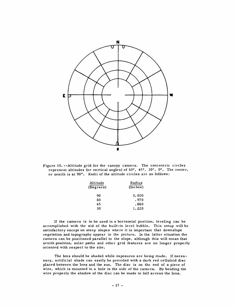
• Figure 10. --Altitude grid for the canopy camera. The concentric circles
represent altitudes (or vertical angles) of 60°, 45°, 30.-., 0°. The center, or zenith is at 90°. Radii of the altitude circles are as follows:
Altitude Radius (Degrees) (Inches)
90 0.000 60 • 570 45 • 880 30 1. 220
If the camera is to be used in a horizontal position, leveling can be accomplished with the aid of the built-in level bubble. This setup will be satisfactory except on steep slopes where it is important that downslope vegetation and topography appear in the picture. In the latter situation the camera can be positioned parallel to the slope, although this will mean that zenith position, solar paths and other grid features are no longer properly oriented with respect to the site.
The lens should be shaded while exposures are being made. If necessary, artificial shade can easily be provided with a dark red celluloid disc placed between the lens and the sun. The disc is on the end of a piece of wire, which is mounted in a hole in the side of the camt.•ra. By bending the wire properly the shadow of the disc can be made to fall across the lens.
- 17 -
CXl
I .o !I
/..
to·;.
-~
"'
S;,2
o•;.
I .7
.6
~
.5"
.-4
_g
.2
.I I rr
cec---
-- "X
-
A
Fig
ure
11
. --
Meth
od
of
dete
rmin
ing
10
ban
dso
feq
ual
are
a o
n t
he s
urf
ace o
f a
hem
isp
here
. "A
" re
pre
sen
ts
a q
uart
er-
cir
cle
w
ith
ra
diu
s
of
on
e
un
it.
Ho
rizo
nta
l li
nes
on
e -
ten
th
un
it a
part
are
dra
wn
th
rou
gh
th
e
qu
art
er
-cir
cle
, th
en
ra
dii
are
co
n
str
uc
ted
to
th
e
po
ints
wh
ere
th
e h
ori
zo
nta
l li
nes
inte
rsect
the c
ircu
mfe
ren
ce (
10
percen
t,
20
per
cen
t, etc
.).
If th
is q
uart
er-
cir
cle
is
ro
tate
d 3
60
" o
n
its
y ax
is
a h
em
isp
her
ica
l su
rface
wil
l b
e
Uf
""'
.J
B
form
ed
wit
h e
qu
al-
are
a b
an
ds
defi
ned
by
th
e te
n
perc
en
tile
in
terc
ep
ts.
To
co
mp
ute
th
e v
ert
ical
an
gle
s th
e f
un
cti
on
s in
a
= y
I 1
is
use
d,
thu
s th
e
sin
o
f th
e a
ng
le
to t
he
10
-perc
en
tile
in
terc
ep
t is
. 9
/1 o
r.
9 (a
=
64
" -0
9')
; th
e s
in o
f th
e 2
0-p
erc
en
tile
in
terc
ep
t is
. 8
/1 o
r .
8 (a
= 5
3"
-08
'),
etc
. (s
ee "
B"
ab
ov
e).

F igure 12. - - The completed canopy camera. Note a rrangement of l enses, l evel vial, film hol der and celluloid sun shade . In field u s e the camera is mounted on a ball - and - socket tripod head, which is screwed to a steel stake . It is then leveled and oriented with the twin proje ctions toward the no rth (top of photo) .
- 19 -
EXPOSURE
Once the camera is properly set up, adjust the shutter speed, cock the shutter, and make the exposure. No adjustment of the iris diaphragm will b e necessary as the diaphragm is kept fully ope n at all times.
Shutter speeds will be relatively slow, ranging from 1/25 to ZO seconds or more, depending on light, type of film, and filters. Most of the Prontor II shutters now used in canopy cameras have shown a tendency to stick at slow speeds, so the "Bulb" settinghas been used almost exclusively. Examples of exposure times for ASA ZOO film with K-2 filter are:
Bright sun (lens shaded): 3 seconds Cloudy: 5 seconds
A certain amount of practice will be necessary before the photographer can obtain optimum exposures under a wide varie ty of conditions.
FILM
The ideal film for the camera should permit on-the-spot de velopment as a check on exposure and equipment operation; it should also provide ntgatives so that duplicate prints and enlargements can be made. Also, the film should be relatively fast (ASA 100 or faster).
Two good choices among films presently available are Polapan 200 (ASA 200) and Plus -X (ASA 160). First, the Polapan film is used to de.termine exposure, then for the permanent record a slightly longer exposure is made on Plus -X.
A new Polaroid film (Polaroid 55 P/N) soon to be marketed may supersede both these films for certain uses with the canopy camera. This film, with an ASA rating of 100, can be deve loped on the spot, and also produces negatives.
FILTERS
Gelatin filters the diameter of the shutter barrel can easily b e cemented (or pressed) into place immediately b e low the pinhole. A yellow K2 filter is strongly recommended for ordinary use because of the improved definition produced at the edge of the photographs.
STEREO PHOTOGRAPHY
Good stereo vision of tree canopies can be achieved with paired photographs taken fromground positions 4-1/2 inches apart. A shorter "base" is necessary for very close objects such as brush, and a longer base for distant features such as topographic horizons and clouds.
- zo -

SUMMARY
The canopy camera provides an inexpensive means of taking wide-angle photographs of vegetation canopy and other overhead subjects. The circular photographs produced cover the entire hemisphere from horizon to horizon. Materials for the camera cost about $60 and by following the directions carefully, a person can assemble the camera without special tools or experience.
The optical system is comprised of a 0. 007 -inch pinhole and two glass lenses, one a meniscus type, the other planoconcave. Light received from a 180° field of view is contracted by the lenses to about 108°, after which it passes through the pinhole and forms an image 3. 6 inches in diameter at the film plane.
The camera is housed in a wooden box with outside dimens.ions of 9x9x6-l/4 inches.
Exposures are controlled by a leaf-type shutter; the lenses are fastened to the upper face of the shutter housing and the pinhole to the inner barrel, close to the shutter leaves. A 4x5 Graflok back built into the camera accepts either standard or Polaroid film holders.
To provide a means for estimating vegetation coverage in different portions of the sky, two grids have been devised which are used as overlays on canopy photographs. On one grid, called the "equal-area grid," the hemisphere is divided into 10 bands, each of which represents 10 percent of the hemisphere; these bands are each further divided into 8 compartments. The other grid is the "altitude" type, with concentric circles representing altitudes of 30°, 45°, and 60°. On both grids, the center is the zenith and the perimeter is the horizon.
In field use, the camera is mounted on a steel stake or a tripod with the lens pointing upward. Exposures are made in the same manner as with ordinary 4x5 cameras except that slower shutter speeds are required.
With paired photographs taken at the proper spacing, the canopy can be viewed in stereo.
- Zl -

Anonymous. [n. d.].
Cialdea, R. 1956.
Clark, Frank G. 1961.
Codd, Ashton R. 1959.
Conrady, A. E. 1957.
Dirmhirn, Inge. 1958.
LITERATURE CITED
Robin Hill camera for photogJ:aphlng the whole sky. Brochure Jl. and J. Beck, Ltd., 69 Mortimer St., London, W. 1 4 pp., illus.
A photographic apparatus with a wide field for recording the whole sky. A. Geofis., 9, 451-467. f Abstracted in Phys. Abs. 61: 79, 1958. J
A hemispherical forest photocanopymeter. 59: 103-105, illus.
Jour. Forestry
The photocanopyometer. West. Snow Con£. Proc. 17 -Zl, Wus.
Applied optics and optical design. 518 pp., Ulus. New· York.
Wide angle sky photography as an aid to radiation research. Arch. fur Meteorologie, Geophysic und Bioklimatologie, Ser. B. Vienna 8(3/4): 336-351, Wus.
Evans, G. C., and Coombe, D. E. 1959. Hemispherical and woodland canopy photography and the
light climate. Jour. Ecol. 47: 103-113, illus.
Lubschez, Ben L. 1935. Pinhole photography. The new Photo-Minature, Old Series
Wood, Robert W.
v.l8, No. Z08, New Series No. 3, pp 117-148. Tenant and Ward, 70 5th Avenue, New York.
1934. Physical optics. Ed. 3. 846 pp., Wus. New York.
~ ·-CSU, ft. OolllDI - zz -
