the canalta dual chamber orifice fitting - 品/1.流量/2-canalta... · pdf fileto...
TRANSCRIPT
An ISO 9001:2008 registered company
Phone: 403.342.4494Email: [email protected]
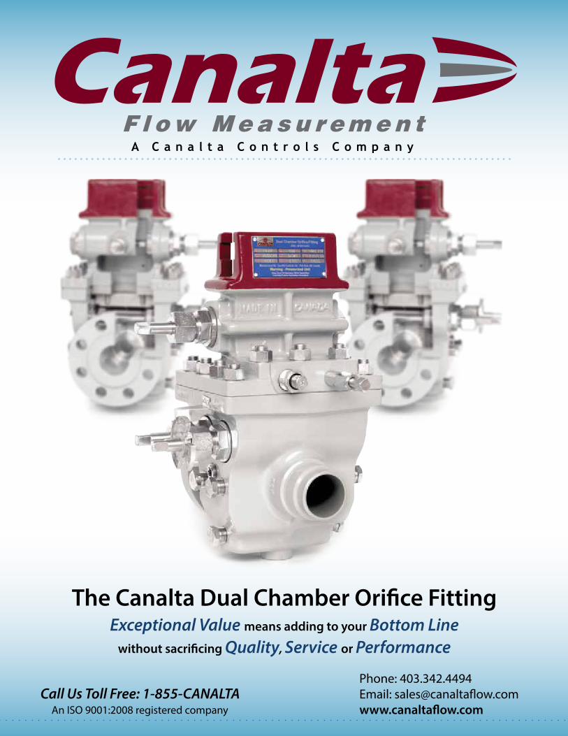
Exceptional Value means adding to your Bottom Linewithout sacrificing Quality, Service or Performance
The Canalta Dual Chamber Orifice Fitting
Call Us Toll Free: 1-855-CANALTA
For more information or to order, contact us at Phone: 403.342.4494 | Fax: 403.346.7110 | Email: [email protected] | Web: www.canaltaflow.com
3 2
An ISO 9001:2008 Registered Company
The Soft Seat Valve Seal is available for all dual chamber models. Effective in all scenarios, but particularly suited to low pressure applications, this unique design enables a bubble-tight seal between the upper and lower chambers without the need for frequent lubrication. The specially machined seal channel helps prevent O-ring dislocation, and the O-ring seals incorporated are available in a wide variety of compositions.
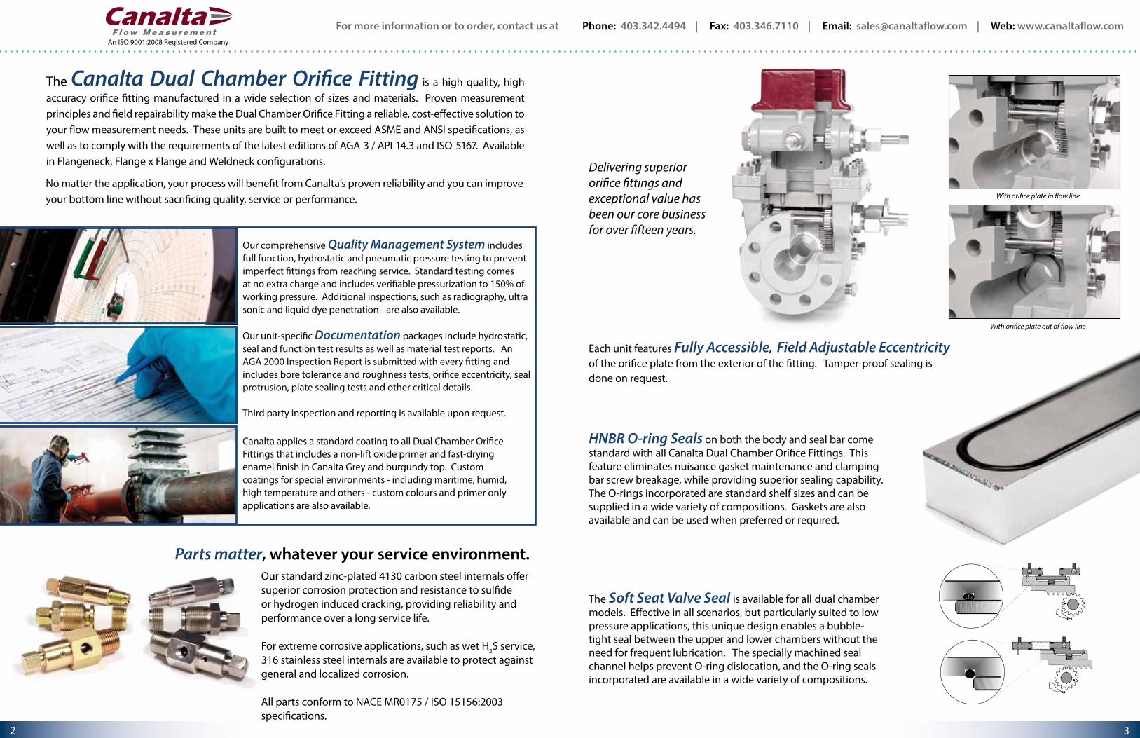
With orifice plate in flow line
With orifice plate out of flow line
HNBR O-ring Seals on both the body and seal bar come standard with all Canalta Dual Chamber Orifice Fittings. This feature eliminates nuisance gasket maintenance and clamping bar screw breakage, while providing superior sealing capability. The O-rings incorporated are standard shelf sizes and can be supplied in a wide variety of compositions. Gaskets are also available and can be used when preferred or required.
Each unit features Fully Accessible, Field Adjustable Eccentricity of the orifice plate from the exterior of the fitting. Tamper-proof sealing is done on request.
Our comprehensive Quality Management System includes full function, hydrostatic and pneumatic pressure testing to prevent imperfect fittings from reaching service. Standard testing comes at no extra charge and includes verifiable pressurization to 150% of working pressure. Additional inspections, such as radiography, ultra sonic and liquid dye penetration - are also available.
Our unit-specific Documentation packages include hydrostatic, seal and function test results as well as material test reports. An AGA 2000 Inspection Report is submitted with every fitting and includes bore tolerance and roughness tests, orifice eccentricity, seal protrusion, plate sealing tests and other critical details.
Third party inspection and reporting is available upon request.
Canalta applies a standard coating to all Dual Chamber Orifice Fittings that includes a non-lift oxide primer and fast-drying enamel finish in Canalta Grey and burgundy top. Custom coatings for special environments - including maritime, humid, high temperature and others - custom colours and primer only applications are also available.
The Canalta Dual Chamber Orifice Fitting is a high quality, high accuracy orifice fitting manufactured in a wide selection of sizes and materials. Proven measurement principles and field repairability make the Dual Chamber Orifice Fitting a reliable, cost-effective solution to your flow measurement needs. These units are built to meet or exceed ASME and ANSI specifications, as well as to comply with the requirements of the latest editions of AGA-3 / API-14.3 and ISO-5167. Available in Flangeneck, Flange x Flange and Weldneck configurations.
No matter the application, your process will benefit from Canalta’s proven reliability and you can improve your bottom line without sacrificing quality, service or performance.
Our standard zinc-plated 4130 carbon steel internals offer superior corrosion protection and resistance to sulfide or hydrogen induced cracking, providing reliability and performance over a long service life.
For extreme corrosive applications, such as wet H2S service, 316 stainless steel internals are available to protect against general and localized corrosion.
All parts conform to NACE MR0175 / ISO 15156:2003 specifications.
Parts matter, whatever your service environment.
Delivering superior orifice fittings and exceptional value has been our core business for over fifteen years.

For more information or to order, contact us at Phone: 403.342.4494 | Fax: 403.346.7110 | Email: [email protected] | Web: www.canaltaflow.com
5 4
An ISO 9001:2008 Registered Company
1 FLOW CONDITIONING ACCESSORIES
1
4
25
3
METER RUNS
All Canalta Dual Chamber Orifice Fittings can be supplied with complete custom-designed Meter Runs and Flow Conditioning Solutions that meet your exact specification or performance needs.
3 WELDING SPECIFICATIONT
Thb
tc
__
2 END CONNECTION OPTIONSCanalta Meter Runs can be fabricated with a variety of standard tube ends. All inner surface welds are precision ground and inspected to meet exacting I.D. surface and roundness tolerances. Per your requirements, two and three-piece meter runs can have dissimilar end types up and downstream of the orifice fitting.
Welding Neck
Flanged(Raised Face / RTJ)
Threaded
90 ° Elbow
4 BRANCH CONNECTION OPTIONSIndustry standard offerings provide one 1” and one 3/4” branch connection on the downstream spool. Our custom meter tube design capability allows us to fabricate nearly any combination of weldolets, sockolets, flanged outlets, threadolets and latrolets in any orientation.
0
(Right)
180
90
A - AT.O.L. ORIENTATION
270(Left)
With literally endless configurations possible, Canalta will custom design and fabricate your meter run for any application.
ACCURACY, RELIABILITY, PERFORMANCE.
5 METER RUN SPECIFICATION PLATEAll Canalta Meter Runs include a specification plate mounted immediately upstream of the orifice fitting. These spec plates detail pipe schedule, pressure rating, maximum beta, maximum orifice and other information essential to proper operation.
Whether the size is 2” or 30”, high or low pressure, wet, dry or corrosive service, we can put together a custom meter run package that meets your specification or performance needs and perfectly matches your Canalta Orifice Fitting.
You trust Canalta at the orifice plate. When accuracy counts, trust Canalta up and downstream, too.
We’ve been working to AGA-3 / API 14.3 and ISO 5167-1 specifications for over fifteen years. Skilled technicians, engineers and inspectors work together to manufacture first-rate meter tubes out of pipe carefully selected and prepared with the appropriate surface requirements, roundness and I.D. tolerances. Hydrostatic test results are included as a standard. PWHT stress relief, ultra-sonic and liquid dye penetration test results are available on request. Our rigorous inspection regime and comprehensive documentation mean you can be sure your meter run is reliable, exceptionally accurate and ready for service.
Each Canalta Meter Run is professionally fabricated by our team of certified “B” Pressure Welders and experienced pipe finishers to meet and exceed the stringent specifications of AGA /API/ISO. Our welding procedures are registered with the Alberta Boiler and Safety Association (ABSA) and are in accordance with the applicable ASME Boiler and Pressure Vessel Codes. Canalta will ensure that all of your NDT and stress relieving requirements are met with full documentation.
The goal of meter run design is to account for swirl and turbulence. Suitable for a wide range of flow measurement methods and equipment, Canalta’s Contour™ lineup of Flow Conditioners, Flow Conditioner Housings and Straightening Vanes will help you develop the flow profile you need to achieve maximum performance and accuracy in the field.

For more information or to order, contact us at Phone: 403.342.4494 | Fax: 403.346.7110 | Email: [email protected] | Web: www.canaltaflow.com
7 6
An ISO 9001:2008 Registered Company
Type “K” Standard 2000 Edition Seal AssemblyThis is the standard seal assembly supplied with all orifice fittings from sizes 2” through 8”. This unit is used with a .562” seal gap for fittings sizes 2” through 6”, and with a .688” seal gap for 8” fittings. The single downstream seal function offers superior sealing capability while reducing seal damage during insertion. Plate seal bypass tested down to 1” water column.The seal assembly is comprised of an elastomer seal and one stainless steel retainer ring. Exacting and repeatable concentricity is maintained with the metal to metal contact throughout the entire 360° circumference of the orifice plate to the plate carrier mechanism.
Teflon Snap SealThe Teflon Snap Seal provides positive plate sealing in the harshest of process environments. The two-piece design snaps over the orifice plate without the use of metal clips or retainers. A specially designed recess absorbs the insertion pressures, minimizing permanent compression and distortion.
The raised section adjacent to the recess creates a positive seal against the orifice plate, preventing bypass leakage. These two unique design features enhance seal performance while extending the life expectancy of the seal assembly.
HNBR SEAL RING
ORIFICE PLATE STAINLESS STEELRETAINING RING
FLOW
BEVEL
TEFLON SNAP RING
TEFLON SNAP RINGORIFICE PLATE
FLOW
BEVEL
FLOW
BEVEL
ORIFICE PLATE SEAL OPTIONS & CARRIER ASSEMBLIES
Bonded SealThis is the standard seal supplied with all Canalta Orifice Fitting model sizes 10" and larger. Designed with a unique "hollow core" recess, this seal has impressive expansion and contraction capabilities when compared to traditional solid rubber seals. The recess allows the seal to absorb insertion pressures, minimizing tearing, distortion and permanent compression. The 80 duro HNBR seal is adhesively bonded to the orifice plate, creating total and permanent contact between the plate and seal and preventing bypass leakage.
Legacy Replacement SealsCanalta supplies a selection of legacy plate seals for situations in which direct and exact seal replacement is required or preferred. Models include two piece clip-style Teflon, solid core HNBR or Nitrile and the stainless steel dual ring assemblies.
We will also work with you to custom design and manufacture purpose-built seals for your unique or special applications.
For more information or to order, contact us at Phone: 403.342.4494 | Fax: 403.346.7110 | Email: [email protected] | Web: www.canaltaflow.com
9 8
An ISO 9001:2008 Registered Company
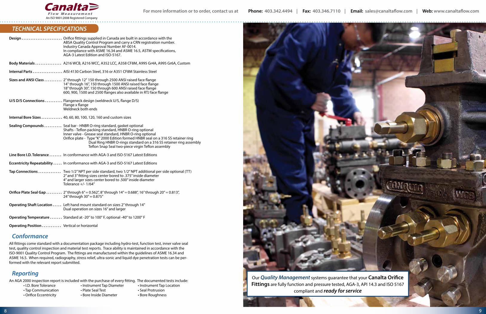
All fittings come standard with a documentation package including hydro-test, function test, inner valve seal test, quality control inspection and material test reports. Trace ability is maintained in accordance with the ISO-9001 Quality Control Program. The fittings are manufactured within the guidelines of ASME 16.34 and ASME 16.5. When required, radiography, stress relief, ultra-sonic and liquid dye penetration tests can be per-formed with the relevant report submitted.
An AGA 2000 inspection report is included with the purchase of every fitting. The documented tests include: • I.D. Bore Tolerance • Instrument Tap Diameter • Instrument Tap Location • Tap Communication • Plate Seal Test • Seal Protrusion • Orifice Eccentricity • Bore Inside Diameter • Bore Roughness
Conformance
Reporting
Design . . . . . . . . . . . . . . . . . . . . . . .
Body Materials . . . . . . . . . . . . . . .
Internal Parts . . . . . . . . . . . . . . . . .
Sizes and ANSI Class . . . . . . . . . .
U/S D/S Connections . . . . . . . . . .
Internal Bore Sizes . . . . . . . . . . . .
Sealing Compounds . . . . . . . . . .
Line Bore I.D. Tolerance . . . . . . .
Eccentricity Repeatability . . . . .
Tap Connections . . . . . . . . . . . . .
Orifice Plate Seal Gap . . . . . . . . .
Operating Shaft Location . . . . .
Operating Temperature . . . . . . .
Operating Position . . . . . . . . . . .
Orifice fittings supplied in Canada are built in accordance with the ABSA Quality Control Program and carry a CRN registration number.Industry Canada Approval Number AF-0014.In compliance with ASME 16.34 and ASME 16.5, ASTM specifications, AGA-3 Latest Edition and ISO-5167.
A216 WCB, A216 WCC, A352 LCC, A358 CF8M, A995 Gr4A, A995 Gr6A, Custom
AISI 4130 Carbon Steel, 316 or A351 CF8M Stainless Steel
2” through 12" 150 through 2500 ANSI raised face flange 14" through 16”, 150 through 1500 ANSI raised face flange18” through 30”, 150 through 600 ANSI raised face flange600, 900, 1500 and 2500 flanges also available in RTJ face flange
Flangeneck design (weldneck U/S, flange D/S)Flange x flangeWeldneck both ends
40, 60, 80, 100, 120, 160 and custom sizes
Seal bar - HNBR O-ring standard, gasket optionalShafts - Teflon packing standard, HNBR O-ring optionalInner valve - Grease seal standard, HNBR O-ring optionalOrifice plate - Type “K” 2000 Edition formed HNBR seal on a 316 SS retainer ring Dual Ring HNBR O-rings standard on a 316 SS retainer ring assembly Teflon Snap Seal two-piece virgin Teflon assembly
In conformance with AGA-3 and ISO-5167 Latest Editions
In conformance with AGA-3 and ISO-5167 Latest Editions
Two 1/2” NPT per side standard, two 1/2” NPT additional per side optional (TT) 2” and 3” fitting sizes center bored to .375” inside diameter4” and larger sizes center bored to .500” inside diameterTolerance +/- 1/64”
2” through 6” = 0.562”, 8” through 14” = 0.688”, 16” through 20” = 0.813”, 24” through 30” = 0.875”
Left hand mount standard on sizes 2” through 14”Dual operation on sizes 16” and larger
Standard at -20° to 100° F, optional -40° to 1200° F
Vertical or horizontal
TECHNICAL SPECIFICATIONS
Our Quality Management systems guarantee that your Canalta Orifice Fittings are fully function and pressure tested, AGA-3, API 14.3 and ISO 5167
compliant and ready for service

For more information or to order, contact us at Phone: 403.342.4494 | Fax: 403.346.7110 | Email: [email protected] | Web: www.canaltaflow.com
11 10
An ISO 9001:2008 Registered Company
To find the latest editions of the complete data tables, visit us online at www.canaltaflow.com
11
12
9G
9B
52
14
10G 10C
10E
10D
18A
17A
18D
3
1715
19
22A
25A
28E
56
56 56
55
30304 55
55
312
5A
25
26
20A26A
25C25E2022A25A28A
16
5B
4A
18FH
18GH
5
1D
1G
241J
1K
1H
23A5432
23B33
50
8H
8K13588
2” - 14” Grease Type Dual Chamber ModelsItem Qty. Description Material
1 1 Equalizer Valve Assembly 4130 YZP CS / 316 SS
1G 1 Equalizer Valve Stem 4130 YZP CS / 316 SS
1H 1 Equalizer Valve Packing Nut 4130 YZP CS / 316 SS
1D 1 Equalizer Ball 316 SS
1K 1 Equalizer Packing Washer 4130 YZP CS / 316 SS
1J 1 Equalizer Packing Teflon
2 1 Operating Wrench Coated Cast Iron
3 1 Valve Strip 17.4PH - H1150 SS
4 1 Flangnek Body WCB / LCC / SS
4A 1 Body O-ring HNBR
5 3 Shaft & Pinion Gears 4130 YZP CS / CF8M SS
5A 1 Slide Valve Indicator Plate Cast Aluminum
5B 1 Slide Valve Indicator Pointer 316 SS
8 1 Plate Carrier 4130 YZP CS / CF8M SS
8K 1 “K” Style Retaining Ring 316 SS
8H 1 Seal Ring HNBR
9G 1 Seal Bar with O-ring Groove 1018 YZP
9B 1 Seal Bar O-ring HNBR
10C 1 Bleeder Valve Body 4130 YZP CS / 316 SS
10D 1 Bleeder Valve Needle 4130 YZP CS / 316 SS
Item Qty. Description Material
10E 1 Bleeder Valve O-ring HNBR
10G 1 Bleeder Valve Set Screw
11 A/R Clamping Bar Screws Case Hardened 4140 CS
12 1 Clamping Bar 1018 YZP CS
13 1 Orifice Plate 304 SS / 316 SS
14 1 Top Housing WCB / LCC / SS
15 A/R Valve Springs 316 SS
16 2 Valve Carrier Guides CF8M SS
17 1 Valve Carrier 4130 YZP CS / CF8M SS
17A 2 Valve Carrier Stop Pins 316 SS
18A 1 Valve Seat (Grease type) 4130 CS / CF8M SS
18D A/R Valve Seat Screws 304 SS
18FH 1 Valve Seat Top O-ring HNBR
18GH 1 Valve Seat Grease Port Seal HNBR
19 3 Bearing Plug 4130 YZP CS
20 3 Stuffing Box 4130 YZP CS
20A 3 Stuffing Box Outer Gland Seals HNBR
22A 6 Stuffing Box Gaskets 316 SS
23 1 Grease Gun Assembly 4130 YZP CS / 316 SS
23A 1 Grease Gun Stem 4130 YZP CS / 316 SS
Item Qty. Description Material
23B 1 Grease Gun Body 4130 YZP CS / 316 SS
24 1 Double Ball Grease Check Valve 316 SS
25 3 Packing Nuts 4130 YZP CS
25A-F A/R Teflon Packing Sleeve Teflon
25S 1 Complete Packing Set Teflon
26 3 Stuffing Box Glands 316 SS
26A 3 Stuffing Box Inner Gland Seals HNBR
28A 3 Bushing Retainer - Stuffing Box 316 SS
28E 3 Bushing Retainer - Bearing Plug 316 SS
30 2 Drain Plugs A105 CS / 316L SS
31 2 Meter Tap Plugs (Qty = 6 with teletaps) A105 CS / 316L SS
32 A/R Body Hex Nuts A194 YZP CS - 2HM
33 A/R Body Studs A193 YZP CS - B7M
50 1 Operating Plate Color Etched 316 SS
52 1 Specification Plate Color Etched 316 SS
54 A/R Slide Valve Lubricant Grease
55 3 Eccentricity Alignment Pins 18/8 SS
56 3 Eccentricity Alignment Plugs
58 1 Plate Carrier Alignment Screw 18/8 SS
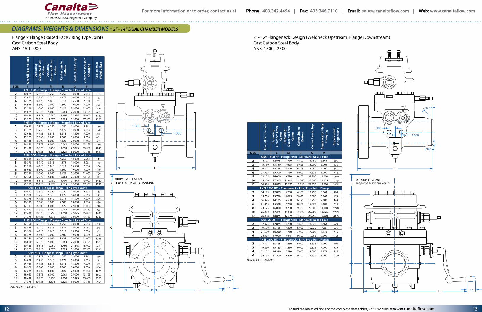
DIAGRAMS, WEIGHTS & DIMENSIONS - 2” - 14” DUAL CHAMBER MODELS
Flangeneck Design (Weldneck Upstream, Flange Downstream)Cast Carbon Steel BodyANSI 150 - 900
MINIMUM CLEARANCE REQ’D FOR PLATE CHANGING
O
N
P
LM 1”
Ove
rall
Face
to F
ace
Ope
ratin
g Cl
eara
nce
From
Ce
nter
Ope
ratin
g Cl
eara
nce
From
Ce
nter
Cent
er L
ine
to
Bott
om
Cent
er L
ine
to T
op
Clea
ranc
e fo
r Pla
te
Chan
ging
App
roxi
mat
e W
eigh
t (lb
s.)
SIZE I L M N O PANSI 150 - Flangeneck - Standard Raised Face
2 10.625 12.875 4.250 4.250 13.000 5.563 1003 13.625 13.750 5.313 4.875 14.000 6.063 1454 12.375 14.125 5.813 5.313 15.500 7.000 2406 14.938 15.500 7.000 7.500 19.000 9.000 3458 15.937 16.000 8.000 8.625 22.000 11.000 520
10 16.188 17.375 9.000 10.063 25.000 13.125 61012 19.438 18.875 10.750 11.750 27.875 15.000 107014 21.376 20.125 11.875 12.625 32.000 17.563 1287
ANSI 300 - Flangeneck - Standard Raised Face2 10.625 12.875 4.250 4.250 13.000 5.563 1003 13.750 13.750 5.313 4.875 14.000 6.063 1454 12.688 14.125 5.813 5.313 15.500 7.000 2406 15.375 15.500 7.000 7.500 19.000 9.000 3458 16.438 16.000 8.000 8.625 22.000 11.000 520
10 16.875 17.375 9.000 10.063 25.000 13.125 61012 19.438 18.875 10.750 11.750 27.875 15.000 107014 21.376 20.125 11.875 12.625 32.000 17.563 1287
ANSI 600 - Flangeneck - Standard Raised Face2 10.625 12.875 4.250 4.250 13.000 5.563 1053 13.875 13.750 5.313 4.875 14.000 6.063 1604 13.250 14.125 5.813 5.313 15.500 7.000 2656 16.063 15.500 7.000 7.500 19.000 9.000 4008 17.250 16.000 8.000 8.625 22.000 11.000 595
10 17.750 17.375 9.000 10.063 25.000 13.125 74512 19.438 18.875 10.750 11.750 27.875 15.000 121514 21.374 20.125 11.875 12.625 32.000 17.563 1475
ANSI 600 - Flangeneck - Ring Type Joint2 10.688 12.875 4.250 4.250 13.000 5.563 1053 13.938 13.750 5.313 4.875 14.000 6.063 1604 13.313 14.125 5.813 5.313 15.500 7.000 2656 16.125 15.500 7.000 7.500 19.000 9.000 4008 17.312 16.000 8.000 8.625 22.000 11.000 595
10 17.813 17.375 9.000 10.063 25.000 13.125 74512 19.438 18.875 10.750 11.750 27.875 15.000 121514 21.375 20.125 11.875 12.625 32.000 17.563 1475
ANSI 900 - Flangeneck - Standard Raised Face2 11.125 12.875 4.250 4.250 13.000 5.563 2053 14.125 13.750 5.313 4.875 14.000 6.063 2154 13.500 14.125 5.813 5.313 15.500 7.000 3006 16.375 15.500 7.000 7.500 19.000 9.000 4908 17.625 16.000 8.000 8.625 22.000 11.000 1095
10 18.000 17.375 9.000 10.063 25.000 13.125 155512 19.438 18.875 10.750 11.750 27.875 15.000 193514 21.375 20.125 11.875 12.625 32.000 17.563 2135
ANSI 900 - Flangeneck - Ring Type Joint2 11.188 12.875 4.250 4.250 13.000 5.563 2053 14.188 13.750 5.313 4.875 14.000 6.063 2154 13.563 14.125 5.813 5.313 15.500 7.000 3006 16.438 15.500 7.000 7.500 19.000 9.000 4908 17.625 16.000 8.000 8.625 22.000 11.000 1095
10 18.063 17.375 9.000 10.063 25.000 13.125 155512 19.438 18.875 10.750 11.750 27.875 15.000 193514 21.375 20.125 11.875 12.625 32.000 17.563 2135
I
CLOSED
OPEN SLID
E
VALV
E
1/16”
37.5°
1.000
1.000
A/R = As required
Data REV 11.1 - 03/2013
For more information or to order, contact us at Phone: 403.342.4494 | Fax: 403.346.7110 | Email: [email protected] | Web: www.canaltaflow.com
13 12
An ISO 9001:2008 Registered Company
To find the latest editions of the complete data tables, visit us online at www.canaltaflow.com
2” - 12” Flangeneck Design (Weldneck Upstream, Flange Downstream)Cast Carbon Steel BodyANSI 1500 - 2500
MINIMUM CLEARANCEREQ’D FOR PLATE CHANGINGP
O
N
M L 1”
I
CLOSED
OPEN SLID
E
VALV
E
1/16”
1.000
1.000
37.5°
Flange x Flange (Raised Face / Ring Type Joint)Cast Carbon Steel BodyANSI 150 - 900
MINIMUM CLEARANCE REQ’D FOR PLATE CHANGING
1”LM
N
O
P
SLID
E
VALV
E
CLOSED
OPEN
1.000
1.000
I
DIAGRAMS, WEIGHTS & DIMENSIONS - 2” - 14” DUAL CHAMBER MODELSO
vera
ll Fa
ce to
Fac
e
Ope
ratin
g Cl
eara
nce
From
Ce
nter
Ope
ratin
g Cl
eara
nce
From
Ce
nter
Cent
er L
ine
to
Bott
om
Cen
ter L
ine
to T
op
Clea
ranc
e fo
r Pla
te
Chan
ging
App
roxi
mat
e W
eigh
t (lb
s.)
SIZE I L M N O PANSI 150 - Flange x Flange - Standard Raised Face
2 10.625 12.875 4.250 4.250 13.000 5.563 1053 12.875 13.750 5.313 4.875 14.000 6.063 1554 12.375 14.125 5.813 5.313 15.500 7.000 2556 14.938 15.500 7.000 7.500 19.000 9.000 3658 15.938 16.000 8.000 8.625 22.000 11.000 550
10 14.625 17.375 9.000 10.063 25.000 13.125 65512 19.438 18.875 10.750 11.750 27.875 15.000 113014 21.375 20.125 11.875 12.625 32.000 17.563 1370
ANSI 300 - Flange x Flange - Standard Raised Face2 10.625 12.875 4.250 4.250 13.000 5.563 1103 13.125 13.750 5.313 4.875 14.000 6.063 1704 12.688 14.125 5.813 5.313 15.500 7.000 2756 15.375 15.500 7.000 7.500 19.000 9.000 4058 16.438 16.000 8.000 8.625 22.000 11.000 605
10 16.875 17.375 9.000 10.063 25.000 13.125 73012 19.438 18.875 10.750 11.750 27.875 15.000 124514 21.375 20.125 11.875 12.625 32.000 17.563 1510
ANSI 600 - Flange x Flange - Standard Raised Face2 10.625 12.875 4.250 4.250 13.000 5.563 1153 13.375 13.750 5.313 4.875 14.000 6.063 1754 13.250 14.125 5.813 5.313 15.500 7.000 3006 16.063 15.500 7.000 7.500 19.000 9.000 4808 17.250 16.000 8.000 8.625 22.000 11.000 700
10 17.750 17.375 9.000 10.063 25.000 13.125 92512 19.438 18.875 10.750 11.750 27.875 15.000 143014 21.375 20.125 11.875 12.625 32.000 17.563 1735
ANSI 600 - Flange x Flange - Ring Type Joint2 10.875 12.875 4.250 4.250 13.000 5.563 1153 13.500 13.750 5.313 4.875 14.000 6.063 1754 13.375 14.125 5.813 5.313 15.500 7.000 3006 16.125 15.500 7.000 7.500 19.000 9.000 4808 17.313 16.000 8.000 8.625 22.000 11.000 710
10 17.813 17.375 9.000 10.063 25.000 13.125 92512 19.438 18.875 10.750 11.750 27.875 15.000 143014 21.375 20.125 11.875 12.625 32.000 17.563 1735
ANSI 900 - Flange x Flange - Standard Raised Face2 12.750 12.875 4.250 4.250 13.000 5.563 2303 13.875 13.750 5.313 4.875 14.000 6.063 2454 13.500 14.125 5.813 5.313 15.500 7.000 3556 16.375 15.500 7.000 7.500 19.000 9.000 6008 18.250 16.000 8.000 8.625 22.000 11.000 1265
10 18.000 17.375 9.000 10.063 25.000 13.125 180012 19.438 18.875 10.750 11.750 27.875 15.000 226014 21.375 20.125 11.875 12.625 32.000 17.563 2515
ANSI 900 - Flange x Flange - Ring Type Joint2 12.875 12.875 4.250 4.250 13.000 5.563 2303 14.000 13.750 5.313 4.875 14.000 6.063 2454 14.469 14.125 5.813 5.313 15.500 7.000 3556 16.500 15.500 7.000 7.500 19.000 9.000 6008 17.625 16.000 8.000 8.625 22.000 11.000 1265
10 18.063 17.375 9.000 10.063 25.000 13.125 180012 19.438 18.875 10.750 11.750 27.875 15.000 226014 21.375 20.125 11.875 12.625 32.000 17.563 2495
Ove
rall
Face
to F
ace
Ope
ratin
g Cl
eara
nce
From
Ce
nter
Ope
ratin
g Cl
eara
nce
From
Ce
nter
Cent
er L
ine
to
Bott
om
Cent
er L
ine
to T
op
Clea
ranc
e fo
r Pla
te
Chan
ging
App
roxi
mat
e W
eigh
t (lb
s.)
SIZE I L M N O PANSI 1500 RF - Flangeneck - Standard Raised Face
2 14.125 12.875 5.750 4.500 13.750 5.563 2053 15.750 13.750 5.625 5.625 15.000 6.063 2754 16.375 14.125 6.500 6.125 16.250 7.000 4456 21.063 15.500 7.750 8.000 19.375 9.000 7108 23.125 16.000 9.750 9.500 22.500 11.000 1240
10 25.250 17.375 11.000 11.500 25.500 13.125 174512 26.938 18.875 12.375 13.250 28.250 15.000 2805
ANSI 1500 RTJ - Flangeneck - Ring Type Joint Flange2 14.125 12.875 5.750 4.500 13.750 5.563 2053 15.750 13.750 5.625 5.625 15.000 6.063 2754 16.375 14.125 6.500 6.125 16.250 7.000 4456 21.063 15.500 7.750 8.000 19.375 9.000 7108 23.125 16.000 9.750 9.500 22.500 11.000 1240
10 25.250 17.375 11.000 11.500 25.500 13.125 174512 26.938 18.875 12.375 13.250 28.250 15.000 2805
ANSI 2500 RF - Flangeneck - Standard Raised Face2 17.375 12.875 4.250 4.625 13.375 5.563 5203 19.500 15.125 7.250 6.000 16.875 7.00 5754 21.500 16.250 7.750 7.000 17.000 7.375 7156 24.438 17.000 8.875 9.500 19.063 9.000 1195
ANSI 2500 RTJ - Flangeneck - Ring Type Joint Flange2 17.375 15.125 7.250 6.000 16.875 7.000 5003 19.250 15.125 7.250 6.000 16.875 7.000 5754 21.125 16.250 7.750 7.000 17.000 7.375 7156 25.125 17.500 9.500 9.500 19.125 9.000 1150
Data REV 11 .1- 03/2013
Data REV 11.1 - 03/2013
For more information or to order, contact us at Phone: 403.342.4494 | Fax: 403.346.7110 | Email: [email protected] | Web: www.canaltaflow.com
15 14
An ISO 9001:2008 Registered Company
11
12
9G 9B
52
510H
23B
18FH
24
18A
17A18D
3
1716
1526B
56
56
30
4
555B
312
2526
25B 26A
25C 25E20
22A 25C
28A
58
4A
1D1G
1J 1K
1H
23A 54
32
33
50
813B
18GH
52
5A
Item Qty. Description Material
1 1 Equalizer Valve Assembly 4130 YZP CS / 316 SS
1G 1 Equalizer Valve Stem 4130 YZP CS / 316 SS
1H 1 Equalizer Valve Packing Nut 4130 YZP CS / 316 SS
1D 1 Equalizer Ball 316 SS
1K 1 Equalizer Packing Washer 4130 YZP CS / 316 SS
1J 1 Equalizer Packing Teflon
2 2 Operating Wrench Coated Cast Iron
3 1 Valve Strip 17.4PH - H1150 SS
4 1 Flangnek Body WCB / LCC / SS
4A 1 Body O-ring HNBR
5 3 Shaft & Pinion Gears 4130 YZP CS / CF8M SS
5A 2 Slide Valve Indicator Plate Cast Aluminum
5B 1 Slide Valve Indicator Pointer 316 SS
8 1 Plate Carrier 4130 YZP CS / CF8M SS
13B 1 Bonded “FLEX” Seal with Orifice Plate HNBR
9G 1 Seal Bar with O-ring Groove 1018 YZP CS
9B 1 Seal Bar O-ring HNBR
10H 1 Bleeder Valve A105N CS
11 A/R Clamping Bar Screws Case Hardened 4140 CS
12 1 Clamping Bar 1018 YZP CS
14 1 Top Housing WCB / LCC / SS
15 A/R Valve Springs 316 SS
16 2 Valve Carrier Guides CF8M SS
17 1 Valve Carrier 4130 YZP CS / CF8M SS
17A 2 Valve Carrier Stop Pins 316 SS
18A 1 Valve Seat (Grease type) 4130 CS / CF8M SS
18D A/R Valve Seat Screws 304 SS
18FH 1 Valve Seat Top O-ring HNBR
18GH 1 Valve Seat Grease Port Seal HNBR
20 6 Stuffing Box 4130 YZP CS
22A 6 Stuffing Box Gaskets 316 SS
23 1 Grease Gun Assembly 4130 YZP CS / 316 SS
23A 1 Grease Gun Stem 4130 YZP CS / 316 SS
23B 1 Grease Gun Body 4130 YZP CS / 316 SS
24 1 Double Ball Grease Check Valve 316 SS
25 6 Packing Nuts 4130 YZP CS
25A-F A/R Teflon Packing Sleeve Teflon
25S 1 Complete Packing Set Teflon
26 6 Stuffing Box Glands 316 SS
26A 6 Stuffing Box Inner Gland Seals HNBR
26B 6 Stuffing Box Outer Gland Seals HNBR
28A 6 Bushing Retainer - Stuffing Box 316 SS
30 2 Drain Plugs A105 CS / 316L SS
31 2 Meter Tap Plugs (Qty = 6 with teletaps) A105 CS / 316L SS
32 A/R Hex Nuts A194 YZP CS - 2HM
33 A/R Body Studs A193 YZP CS - B7M
50 1 Specification Plate Color Etched 316 SS
52 2 Operating Plates Color Etched 316 SS
54 A/R Slide Valve Lubricant Grease
55 3 Eccentricity Alignment Pins 18/8 SS
56 3 Eccentricity Alignment Pin Plugs
58 1 Plate Carrier Alignment Screw 18/8 SS
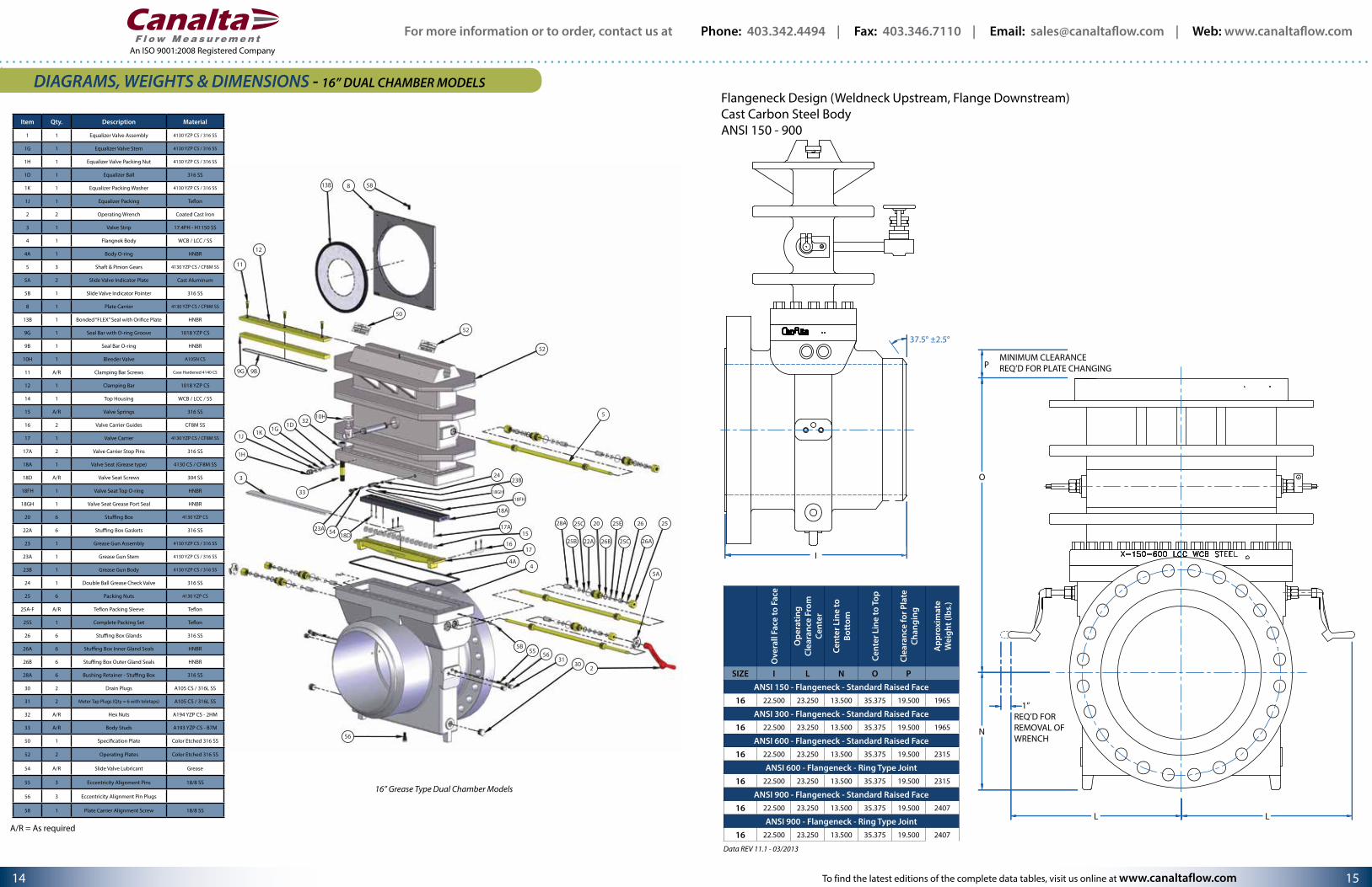
16” Grease Type Dual Chamber Models
A/R = As required
DIAGRAMS, WEIGHTS & DIMENSIONS - 16” DUAL CHAMBER MODELSFlangeneck Design (Weldneck Upstream, Flange Downstream)Cast Carbon Steel BodyANSI 150 - 900
37.5° ±2.5°
I
N
1”REQ’D FORREMOVAL OF WRENCH
MINIMUM CLEARANCE REQ’D FOR PLATE CHANGINGP
O
L L
Ove
rall
Face
to F
ace
Ope
ratin
g Cl
eara
nce
From
Ce
nter
Cent
er L
ine
to
Bott
om
Cent
er L
ine
to T
op
Clea
ranc
e fo
r Pla
te
Chan
ging
App
roxi
mat
e W
eigh
t (lb
s.)
SIZE I L N O PANSI 150 - Flangeneck - Standard Raised Face
16 22.500 23.250 13.500 35.375 19.500 1965
ANSI 300 - Flangeneck - Standard Raised Face16 22.500 23.250 13.500 35.375 19.500 1965
ANSI 600 - Flangeneck - Standard Raised Face16 22.500 23.250 13.500 35.375 19.500 2315
ANSI 600 - Flangeneck - Ring Type Joint16 22.500 23.250 13.500 35.375 19.500 2315
ANSI 900 - Flangeneck - Standard Raised Face16 22.500 23.250 13.500 35.375 19.500 2407
ANSI 900 - Flangeneck - Ring Type Joint16 22.500 23.250 13.500 35.375 19.500 2407
Data REV 11.1 - 03/2013
To find the latest editions of the complete data tables, visit us online at www.canaltaflow.com

For more information or to order, contact us at Phone: 403.342.4494 | Fax: 403.346.7110 | Email: [email protected] | Web: www.canaltaflow.com
17 16
An ISO 9001:2008 Registered Company
11
12
37C
41L
9G
44A
44B
44D
44E 44C9B
52
10H
23B
18FH
24
18A
17A18D
3
1716
1526B
56
56
30
4
555B
312
2526
25B 26A
25C 25E20
22A 25C
28A
58
4A
1D1G
1J 1K
1H
23A 54
32
33
5042B
42C 42A 536 35B
41R41B
14
88H
18GH
5A
DIAGRAMS, WEIGHTS & DIMENSIONS - 18” - 30” DUAL CHAMBER MODELS
18” - 30” Grease Type Dual Chamber Models
A/R = As required
Item Qty. Description Material
1 1 Equalizer Valve Assembly 4130 YZP CS / 316 SS
1G 1 Equalizer Valve Stem 4130 YZP CS / 316 SS
1H 1 Equalizer Valve Packing Nut 4130 YZP CS / 316 SS
1D 1 Equalizer Ball 316 SS
1K 1 Equalizer Packing Washer 4130 YZP CS / 316 SS
1J 1 Equalizer Packing Teflon
2 2 Operating Wrench Coated Cast Iron
3 1 Valve Strip 17.4PH - H1150 SS
4 1 Flangnek Body WCB / LCC / SS
4A 1 Body O-ring HNBR
5 4 Shaft & Pinions 4130 YZP CS / CF8M SS
5A 2 Slide Valve Indicator Plate Cast Aluminum
5B 1 Slide Valve Indicator Pointer 316 SS
8 1 Plate Carrier 4130 YZP CS / CF8M SS
9G 1 Seal Bar with O-ring Groove 1018 YZP CS
9B 1 Seal Bar O-ring HNBR
10H 1 Bleeder Valve 4130 YZP CS / 316 SS
11 A/R Clamping Bar Screws Case Hardened 4140 CS
12 1 Clamping Bar 1018 YZP CS
13B 1 Bonded “FLEX” Seal with Orifice Plate HNBR
14 1 Top Housing WCB / LCC / SS
15 A/R Valve Springs 316 SS
16 2 Valve Carrier Guides CF8M SS
17 1 Valve Carrier 4130 YZP CS / CF8M SS
17A 2 Valve Carrier Stop Pins 316 SS
18A 1 Valve Seat (Grease type) 4130 CS / CF8M SS
18D A/R Valve Seat Screws 304 SS
18FH 1 Valve Seat Top O-ring HNBR
18GH 1 Valve Seat Grease Port Seal HNBR
20 6 Stuffing Box 4130 YZP CS
22A 6 Stuffing Box Gaskets 316 SS
23 2 Grease Gun Assembly 4130 YZP CS / 316 SS
23A 2 Grease Gun Stem 4130 YZP CS / 316 SS
23B 2 Grease Gun Body 4130 YZP CS / 316 SS
24 2 Double Ball Grease Check Valve 316 SS
25 6 Packing Nuts 4130 YZP CS
25A-F A/R Teflon Packing Sleeve Teflon
25S 1 Complete Packing Set Teflon
26 6 Stuffing Box Glands 316 SS
26A 6 Stuffing Box Inner Gland Seals HNBR
26B 6 Stuffing Box Outer Gland Seals HNBR
28A 6 Bushing Retainer - Stuffing Box 316 SS
30 2 Drain Plugs A105 CS / 316L SS
31 2 Meter Tap Plugs (Qty = 6 with teletaps) A105 CS / 316L SS
32 A/R Hex Nuts A194 YZP CS - 2HM
33 A/R Body Studs A193 YZP CS - B7M
35B 2 External Shaft Roller 1018 CS
36 1 External Shaft 1018 CS
37C 4 Shaft Bushing Brass
41 1 Plate Carrier Guide (left & right) Cast Carbon Steel
41B 4 Plate Carrier Guide Bolts YZP Steel
42A 1 Plate Carrier Stop Carbon Steel
42B 1 Plate Carrier Stop Bolt B7 Bolting
42C 1 Plate Carrier Stop Bushing Brass
Item Qty. Description Material
44A 1 Travel Brake Body WCB Steel
44B 1 Brake Band Brass
44C 1 Brake Adjustment Bolt YZP Steel
44D 1 Brake Sleeve Carbon Steel
44E 1 Hex Head Bolt Steel
50 1 Specification Plate Color Etched 316 SS
52 2 Operating Plates Color Etched 316 SS
54 A/R Slide Valve Lubricant Grease
55 3 Eccentricity Alignment Pins 18/8 SS
56 3 Eccentricity Alignment Pin Plugs
58 1 Plate Carrier Alignment Screw 18/8 SS
Flange x Flange (Raised Face / Ring Type Joint)Cast Carbon Steel BodyANSI 150 - 900
DIAGRAMS, WEIGHTS & DIMENSIONS - 16” DUAL CHAMBER MODELS
I
MINIMUM CLEARANCE REQ’D FOR PLATE CHANGINGP
O
1”REQ’D FOR REMOVAL OFWRENCH
N
L L
Ove
rall
Face
to F
ace
Ope
ratin
g Cl
eara
nce
From
Ce
nter
Cent
er L
ine
to
Bott
om
Cen
ter L
ine
to T
op
Clea
ranc
e fo
r Pla
te
Chan
ging
App
roxi
mat
e W
eigh
t (lb
s.)
SIZE I L N O PANSI 150 - Flange x Flange - Standard Raised Face
16 22.500 23.250 13.500 35.375 19.500 2060
ANSI 300 - Flange x Flange - Standard Raised Face16 22.500 23.250 13.500 35.375 19.500 2300
ANSI 600 - Flange x Flange - Standard Raised Face16 22.500 23.250 13.500 35.375 19.500 2680
ANSI 600 - Flange x Flange - Ring Type Joint16 22.500 23.250 13.500 35.375 19.500 2680
ANSI 900 - Flange x Flange - Standard Raised Face16 22.500 23.250 13.500 35.375 19.500 2867
ANSI 900 - Flange x Flange - Ring Type Joint16 22.500 23.250 13.500 35.375 19.500 2867
Data REV 11.1 - 03/2013
To find the latest editions of the complete data tables, visit us online at www.canaltaflow.com
For more information or to order, contact us at Phone: 403.342.4494 | Fax: 403.346.7110 | Email: [email protected] | Web: www.canaltaflow.com
19 18
An ISO 9001:2008 Registered Company
To find the latest editions of the complete data tables, visit us online at www.canaltaflow.com
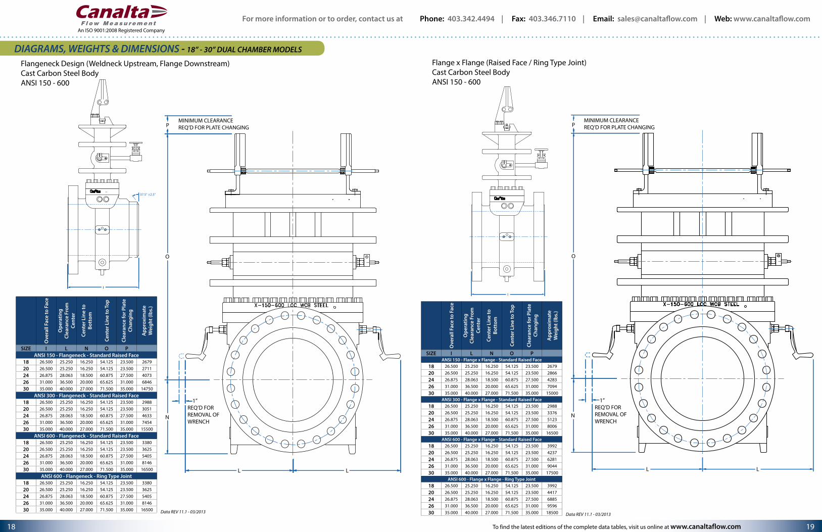
Flangeneck Design (Weldneck Upstream, Flange Downstream)Cast Carbon Steel BodyANSI 150 - 600
37.5° ±2.5°
I
N
1”REQ’D FORREMOVAL OF WRENCH
MINIMUM CLEARANCE REQ’D FOR PLATE CHANGINGP
O
L L
Flange x Flange (Raised Face / Ring Type Joint)Cast Carbon Steel BodyANSI 150 - 600
I
MINIMUM CLEARANCE REQ’D FOR PLATE CHANGINGP
O
1”REQ’D FOR REMOVAL OFWRENCH
N
L L
DIAGRAMS, WEIGHTS & DIMENSIONS - 18” - 30” DUAL CHAMBER MODELSO
vera
ll Fa
ce to
Fac
e
Ope
ratin
g Cl
eara
nce
From
Ce
nter
Cent
er L
ine
to
Bott
om
Cent
er L
ine
to T
op
Clea
ranc
e fo
r Pla
te
Chan
ging
App
roxi
mat
e W
eigh
t (lb
s.)
SIZE I L N O PANSI 150 - Flangeneck - Standard Raised Face
18 26.500 25.250 16.250 54.125 23.500 267920 26.500 25.250 16.250 54.125 23.500 271124 26.875 28.063 18.500 60.875 27.500 407326 31.000 36.500 20.000 65.625 31.000 684630 35.000 40.000 27.000 71.500 35.000 14750
ANSI 300 - Flangeneck - Standard Raised Face18 26.500 25.250 16.250 54.125 23.500 298820 26.500 25.250 16.250 54.125 23.500 305124 26.875 28.063 18.500 60.875 27.500 463326 31.000 36.500 20.000 65.625 31.000 745430 35.000 40.000 27.000 71.500 35.000 15500
ANSI 600 - Flangeneck - Standard Raised Face18 26.500 25.250 16.250 54.125 23.500 338020 26.500 25.250 16.250 54.125 23.500 362524 26.875 28.063 18.500 60.875 27.500 540526 31.000 36.500 20.000 65.625 31.000 814630 35.000 40.000 27.000 71.500 35.000 16500
ANSI 600 - Flangeneck - Ring Type Joint18 26.500 25.250 16.250 54.125 23.500 338020 26.500 25.250 16.250 54.125 23.500 362524 26.875 28.063 18.500 60.875 27.500 540526 31.000 36.500 20.000 65.625 31.000 814630 35.000 40.000 27.000 71.500 35.000 16500
Ove
rall
Face
to F
ace
Ope
ratin
g
Cl
eara
nce
From
Ce
nter
Cent
er L
ine
to
Bott
om
Cent
er L
ine
to T
op
Clea
ranc
e fo
r Pla
te
Chan
ging
App
roxi
mat
e W
eigh
t (lb
s.)
SIZE I L N O PANSI 150 - Flange x Flange - Standard Raised Face
18 26.500 25.250 16.250 54.125 23.500 267920 26.500 25.250 16.250 54.125 23.500 286624 26.875 28.063 18.500 60.875 27.500 428326 31.000 36.500 20.000 65.625 31.000 709430 35.000 40.000 27.000 71.500 35.000 15000
ANSI 300 - Flange x Flange - Standard Raised Face18 26.500 25.250 16.250 54.125 23.500 298820 26.500 25.250 16.250 54.125 23.500 337624 26.875 28.063 18.500 60.875 27.500 512326 31.000 36.500 20.000 65.625 31.000 800630 35.000 40.000 27.000 71.500 35.000 16500
ANSI 600 - Flange x Flange - Standard Raised Face18 26.500 25.250 16.250 54.125 23.500 399220 26.500 25.250 16.250 54.125 23.500 423724 26.875 28.063 18.500 60.875 27.500 628126 31.000 36.500 20.000 65.625 31.000 904430 35.000 40.000 27.000 71.500 35.000 17500
ANSI 600 - Flange x Flange - Ring Type Joint18 26.500 25.250 16.250 54.125 23.500 399220 26.500 25.250 16.250 54.125 23.500 441724 26.875 28.063 18.500 60.875 27.500 688526 31.000 36.500 20.000 65.625 31.000 959630 35.000 40.000 27.000 71.500 35.000 18500Data REV 11.1 - 03/2013 Data REV 11.1 - 03/2013
For more information or to order, contact us at Phone: 403.342.4494 | Fax: 403.346.7110 | Email: [email protected] | Web: www.canaltaflow.com
21 20
An ISO 9001:2008 Registered Company
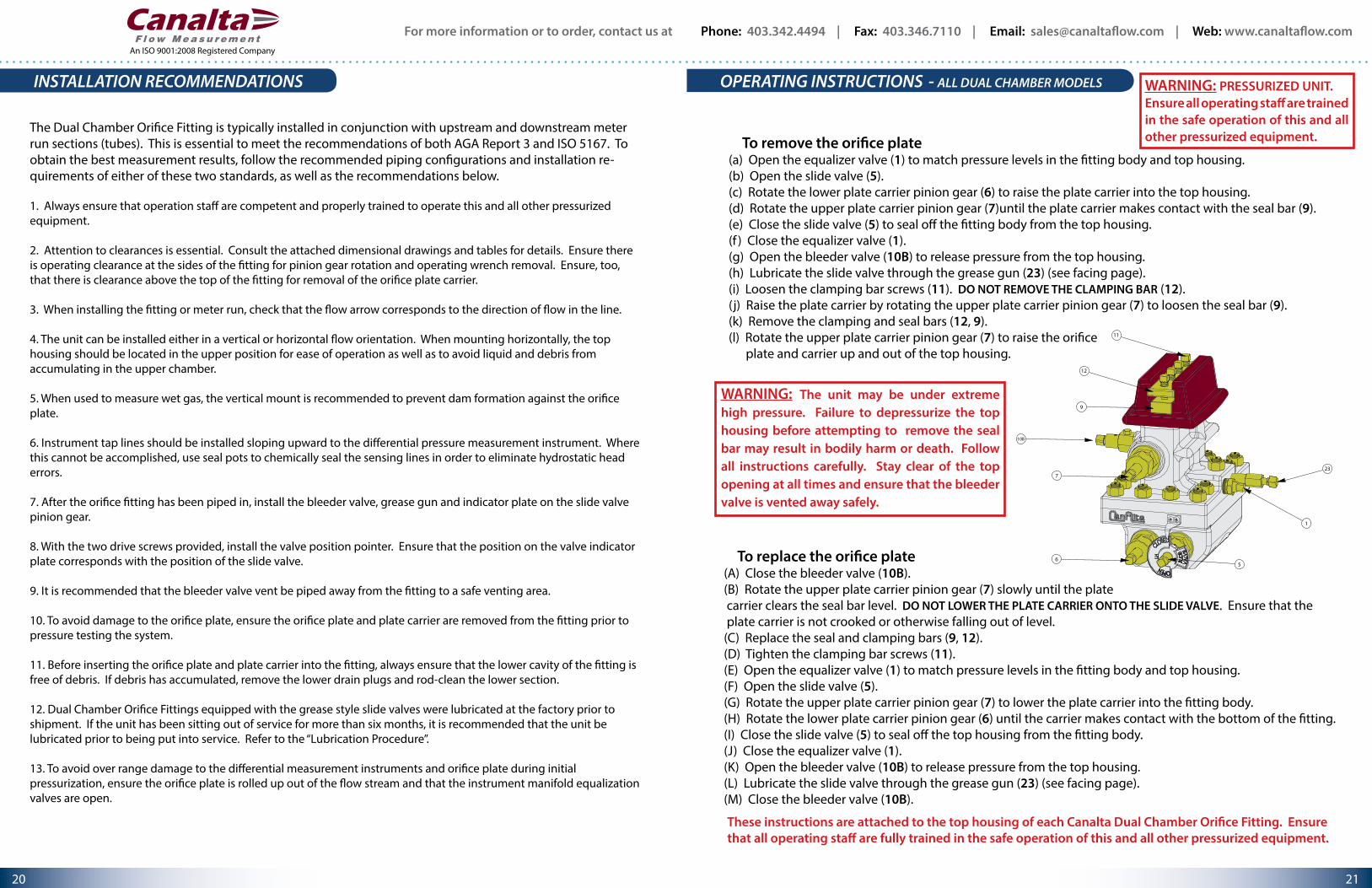
To remove the orifice plate(a) Open the equalizer valve (1) to match pressure levels in the fitting body and top housing.(b) Open the slide valve (5).(c) Rotate the lower plate carrier pinion gear (6) to raise the plate carrier into the top housing.(d) Rotate the upper plate carrier pinion gear (7)until the plate carrier makes contact with the seal bar (9).(e) Close the slide valve (5) to seal off the fitting body from the top housing.(f ) Close the equalizer valve (1).(g) Open the bleeder valve (10B) to release pressure from the top housing.(h) Lubricate the slide valve through the grease gun (23) (see facing page).(i) Loosen the clamping bar screws (11). DO NOT REMOVE THE CLAMPING BAR (12).(j) Raise the plate carrier by rotating the upper plate carrier pinion gear (7) to loosen the seal bar (9).(k) Remove the clamping and seal bars (12, 9).(l) Rotate the upper plate carrier pinion gear (7) to raise the orifice plate and carrier up and out of the top housing.
To replace the orifice plate(A) Close the bleeder valve (10B).(B) Rotate the upper plate carrier pinion gear (7) slowly until the plate carrier clears the seal bar level. DO NOT LOWER THE PLATE CARRIER ONTO THE SLIDE VALVE. Ensure that the plate carrier is not crooked or otherwise falling out of level.(C) Replace the seal and clamping bars (9, 12).(D) Tighten the clamping bar screws (11).(E) Open the equalizer valve (1) to match pressure levels in the fitting body and top housing.(F) Open the slide valve (5).(G) Rotate the upper plate carrier pinion gear (7) to lower the plate carrier into the fitting body.(H) Rotate the lower plate carrier pinion gear (6) until the carrier makes contact with the bottom of the fitting.(I) Close the slide valve (5) to seal off the top housing from the fitting body.(J) Close the equalizer valve (1).(K) Open the bleeder valve (10B) to release pressure from the top housing.(L) Lubricate the slide valve through the grease gun (23) (see facing page).(M) Close the bleeder valve (10B).
WARNING: The unit may be under extreme high pressure. Failure to depressurize the top housing before attempting to remove the seal bar may result in bodily harm or death. Follow all instructions carefully. Stay clear of the top opening at all times and ensure that the bleeder valve is vented away safely.
WARNING: PRESSURIZED UNIT.Ensure all operating staff are trained in the safe operation of this and all other pressurized equipment.
These instructions are attached to the top housing of each Canalta Dual Chamber Orifice Fitting. Ensure that all operating staff are fully trained in the safe operation of this and all other pressurized equipment.
The Dual Chamber Orifice Fitting is typically installed in conjunction with upstream and downstream meter run sections (tubes). This is essential to meet the recommendations of both AGA Report 3 and ISO 5167. To obtain the best measurement results, follow the recommended piping configurations and installation re-quirements of either of these two standards, as well as the recommendations below.
1. Always ensure that operation staff are competent and properly trained to operate this and all other pressurized equipment. 2. Attention to clearances is essential. Consult the attached dimensional drawings and tables for details. Ensure there is operating clearance at the sides of the fitting for pinion gear rotation and operating wrench removal. Ensure, too, that there is clearance above the top of the fitting for removal of the orifice plate carrier.
3. When installing the fitting or meter run, check that the flow arrow corresponds to the direction of flow in the line.
4. The unit can be installed either in a vertical or horizontal flow orientation. When mounting horizontally, the top housing should be located in the upper position for ease of operation as well as to avoid liquid and debris from accumulating in the upper chamber.
5. When used to measure wet gas, the vertical mount is recommended to prevent dam formation against the orifice plate.
6. Instrument tap lines should be installed sloping upward to the differential pressure measurement instrument. Where this cannot be accomplished, use seal pots to chemically seal the sensing lines in order to eliminate hydrostatic head errors.
7. After the orifice fitting has been piped in, install the bleeder valve, grease gun and indicator plate on the slide valve pinion gear.
8. With the two drive screws provided, install the valve position pointer. Ensure that the position on the valve indicator plate corresponds with the position of the slide valve.
9. It is recommended that the bleeder valve vent be piped away from the fitting to a safe venting area.
10. To avoid damage to the orifice plate, ensure the orifice plate and plate carrier are removed from the fitting prior to pressure testing the system.
11. Before inserting the orifice plate and plate carrier into the fitting, always ensure that the lower cavity of the fitting is free of debris. If debris has accumulated, remove the lower drain plugs and rod-clean the lower section.
12. Dual Chamber Orifice Fittings equipped with the grease style slide valves were lubricated at the factory prior to shipment. If the unit has been sitting out of service for more than six months, it is recommended that the unit be lubricated prior to being put into service. Refer to the “Lubrication Procedure”.
13. To avoid over range damage to the differential measurement instruments and orifice plate during initial pressurization, ensure the orifice plate is rolled up out of the flow stream and that the instrument manifold equalization valves are open.
INSTALLATION RECOMMENDATIONS OPERATING INSTRUCTIONS
1
23
56
7
9
12
11
10B
- ALL DUAL CHAMBER MODELS
For more information or to order, contact us at Phone: 403.342.4494 | Fax: 403.346.7110 | Email: [email protected] | Web: www.canaltaflow.com
23 22
An ISO 9001:2008 Registered Company
PREVENTIVE MAINTENANCE
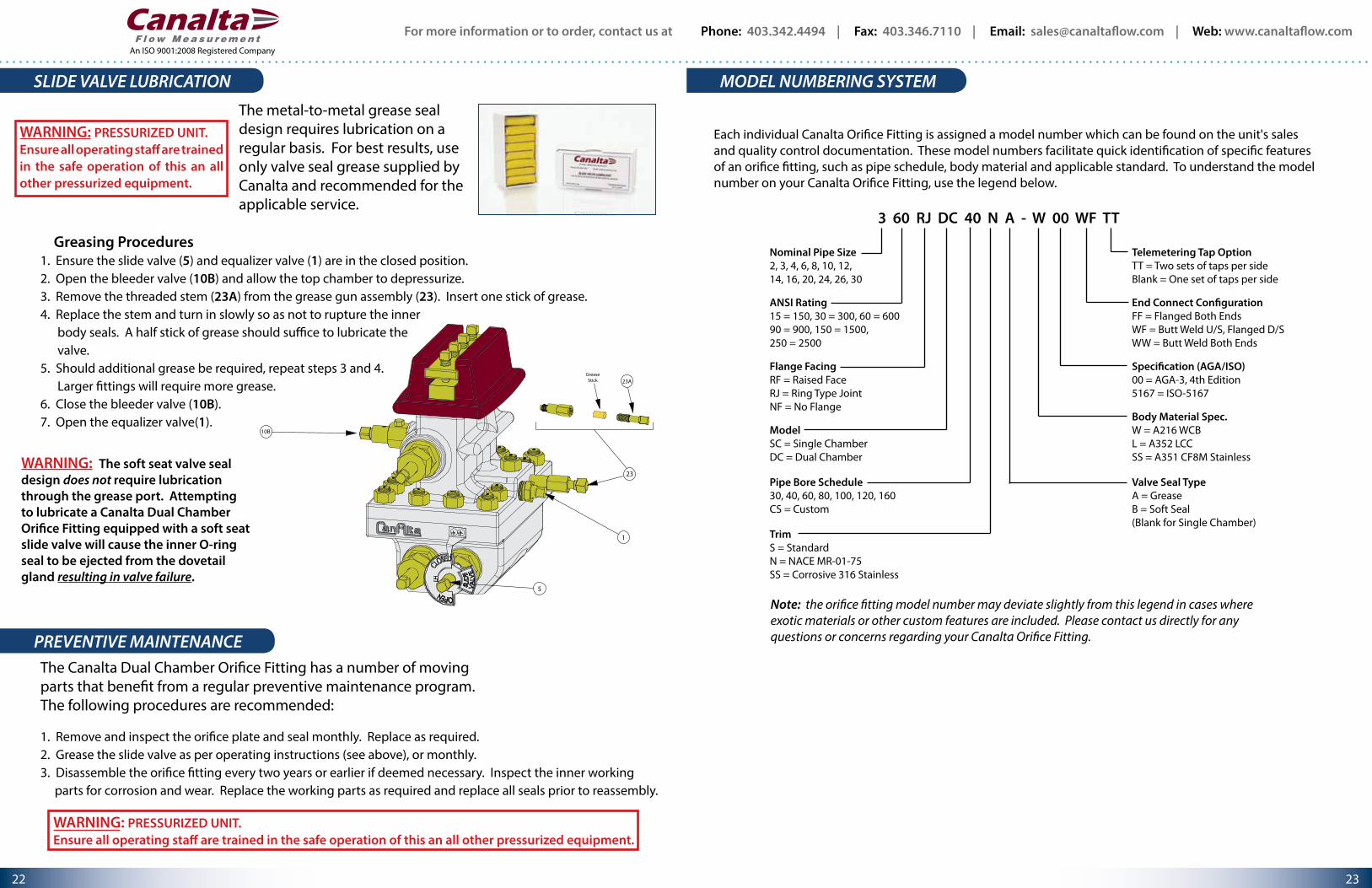
Greasing Procedures1. Ensure the slide valve (5) and equalizer valve (1) are in the closed position.2. Open the bleeder valve (10B) and allow the top chamber to depressurize.3. Remove the threaded stem (23A) from the grease gun assembly (23). Insert one stick of grease.4. Replace the stem and turn in slowly so as not to rupture the inner body seals. A half stick of grease should suffice to lubricate the valve.5. Should additional grease be required, repeat steps 3 and 4. Larger fittings will require more grease.6. Close the bleeder valve (10B).7. Open the equalizer valve(1).
WARNING: The soft seat valve seal design does not require lubrication through the grease port. Attempting to lubricate a Canalta Dual Chamber Orifice Fitting equipped with a soft seat slide valve will cause the inner O-ring seal to be ejected from the dovetail gland resulting in valve failure.
1. Remove and inspect the orifice plate and seal monthly. Replace as required.2. Grease the slide valve as per operating instructions (see above), or monthly.3. Disassemble the orifice fitting every two years or earlier if deemed necessary. Inspect the inner working parts for corrosion and wear. Replace the working parts as required and replace all seals prior to reassembly.
SLIDE VALVE LUBRICATION MODEL NUMBERING SYSTEM
The metal-to-metal grease seal design requires lubrication on a regular basis. For best results, use only valve seal grease supplied by Canalta and recommended for the applicable service.
1
23
5
10B
GreaseStick 23A
The Canalta Dual Chamber Orifice Fitting has a number of moving parts that benefit from a regular preventive maintenance program. The following procedures are recommended:
WARNING: PRESSURIZED UNIT.Ensure all operating staff are trained in the safe operation of this an all other pressurized equipment.
3 60 RJ DC 40 N A - W 00 WF TT
Nominal Pipe Size2, 3, 4, 6, 8, 10, 12,14, 16, 20, 24, 26, 30
ANSI Rating15 = 150, 30 = 300, 60 = 60090 = 900, 150 = 1500, 250 = 2500
Flange FacingRF = Raised FaceRJ = Ring Type JointNF = No Flange
ModelSC = Single ChamberDC = Dual Chamber
Pipe Bore Schedule30, 40, 60, 80, 100, 120, 160CS = Custom
Telemetering Tap OptionTT = Two sets of taps per sideBlank = One set of taps per side
End Connect Con�gurationFF = Flanged Both EndsWF = Butt Weld U/S, Flanged D/SWW = Butt Weld Both Ends
Speci�cation (AGA/ISO)00 = AGA-3, 4th Edition5167 = ISO-5167
Body Material Spec.W = A216 WCBL = A352 LCCSS = A351 CF8M Stainless
TrimS = StandardN = NACE MR-01-75SS = Corrosive 316 Stainless
Valve Seal TypeA = GreaseB = Soft Seal(Blank for Single Chamber)
Each individual Canalta Orifice Fitting is assigned a model number which can be found on the unit's sales and quality control documentation. These model numbers facilitate quick identification of specific features of an orifice fitting, such as pipe schedule, body material and applicable standard. To understand the model number on your Canalta Orifice Fitting, use the legend below.
Note: the orifice fitting model number may deviate slightly from this legend in cases where exotic materials or other custom features are included. Please contact us directly for any questions or concerns regarding your Canalta Orifice Fitting.
WARNING: PRESSURIZED UNIT.Ensure all operating staff are trained in the safe operation of this an all other pressurized equipment.
ADDITIONAL PRODUCT LINESADDITIONAL PRODUCT LINES
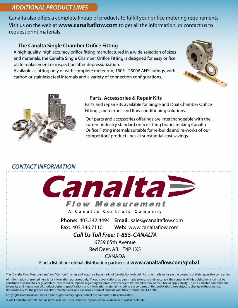
Canalta also offers a complete lineup of products to fulfill your orifice metering requirements. Visit us on the web at www.canaltaflow.com to get all the information, or contact us to request print materials.
The Canalta Single Chamber Orifice FittingA high quality, high accuracy orifice fitting manufactured in a wide selection of sizes and materials, the Canalta Single Chamber Orifice Fitting is designed for easy orifice plate replacement or inspection after depressurization.Available as fitting only or with complete meter run, 150# - 2500# ANSI ratings, with carbon or stainless steel internals and a variety of connection configurations.
CONTACT INFORMATION
Phone: 403.342.4494Fax: 403.346.7110
Email: [email protected] Web: www.canaltaflow.com
6759 65th AvenueRed Deer, AB T4P 1X5
CANADAFind a list of our global distribution partners at www.canaltaflow.com/global
Parts, Accessories & Repair KitsParts and repair kits available for Single and Dual Chamber Orifice Fittings, meter runs and flow conditioning solutions.
Our parts and accessories offerings are interchangeable with the current industry standard orifice fitting brand, making Canalta Orifice Fitting internals suitable for re-builds and re-works of our competitors’ product lines at substantial cost savings.
The "Canalta Flow Measurement" and "Contour" names and logos are trademarks of Canalta Controls Ltd. All other trademarks are the property of their respective companies.
All information presented here is for information purposes only. Though every effort has been made to ensure their accuracy, the contents of this publication shall not be construed as warranties or guarantees, expressed or implied, regarding the products or services described herein, or their use or applicability. Due to Canalta’s commitment to quality and innovation, all product designs, specifications and information material, including the contents of this publication, are subject to change without notice. Responsibility for the proper selection, maintenance and use of any product remains with the customer. SAFETY FIRST.
Copyright, trademark and other forms of proprietary rights protect the contents of this publication.
© 2011 Canalta Controls Ltd. All rights reserved. Unauthorized reproduction in whole or in part is prohibited.
Call Us Toll Free: 1-855-CANALTA