the aura software architecture: an infrastructure for
TRANSCRIPT

The Aura Software Architecture: an Infrastructure for Ubiquitous Computing
João Pedro Sousa, David Garlan
August 2003 CMU-CS-03-183
School of Computer Science Carnegie Mellon University Pittsburgh, PA 15213-3890
Abstract
Computing environments of the future should enable mobile users to take full advantage of the computing capabilities available at each location, while allowing them to focus on their real tasks, rather than being distracted by dealing with the configuration and reconfiguration of com-puter systems to support those tasks. The Aura infrastructure performs automatic configuration and reconfiguration of Ubicomp environments, according to the user’s task and intent.
This report describes the software architecture of the Aura infrastructure, and discusses the un-derlying rational. It describes the architecture from a layered perspective, detailing the partition of responsibility and shared assumptions, as well as from a component-connector perspective, detailing the protocols of interaction between the components (APIs and sequencing). The con-tents and format of the exchanged messages is extensively discussed, as well as the details per-taining service interconnection and decomposition. This report proposes a utility-based ap-proach for modeling user preferences, and details how such models can be exploited for both coarse-grain automatic (re)configuration, and fine-grain adaptation to resource change.
This material is based upon work supported by the National Science Foundation (NSF) under Grant CCR-0205266, and by DARPA under Grant DASA0001. Any opinions, findings, and conclusions or recom-mendations expressed in this material are those of the authors and do not necessarily reflect the views of the NSF, DARPA, or Carnegie Mellon University.

João Pedro Sousa, David Garlan
ii
Keywords: ubiquitous computing, software architecture, task-oriented computing, everyday computing, self-configurable systems, adaptive systems, model-based adaptation, modeling user preferences, utility-based adaptation, resource-adaptive applications.
Aura Software Architecture
iii
Acknowledgments The ideas contained in this technical report owe much to Mahadev Satyanarayanan and Peter Steenkiste for asking the right questions. Finding and polishing the answers to those questions emerged out of detailed discussions with Vahe Poladian, Bradley Schmerl, Rajesh Balan, and Dushyanth Narayanan. In addition, a number of others have contributed in various ways to the work underlying this report (in alphabetical order): Jason Flinn, Lalit Jina, Chiharu Kawatake, Mona Li, Takahide Matsutsuka, Tadashi Okoshi, Bhuricha Sethanandha, Chris Tuttle, Zhenyu Wang, Wei Zhang.
Our appreciation goes to Gaetano Borriello, with Intel Research Seattle, for providing a stimulat-ing and nurturing environment for João P. Sousa, during the summer of 2002, where some of the ideas herein matured.
João Pedro Sousa, David Garlan
iv
Contents
1 INTRODUCTION ............................................................................................................... 5
2 ARCHITECTURAL LAYERS .......................................................................................... 6 2.1 USER-LEVEL STATE.......................................................................................................8
3 WHAT-HOW INTERACTION MODEL ......................................................................... 9 3.1 USER PREFERENCES ....................................................................................................10 3.2 FORMAL UNDERPINNINGS...........................................................................................12
4 CONNECTORS & COMPONENTS............................................................................... 14 4.1 FIBER OF THE CONNECTORS........................................................................................16 4.2 PRISM – EM PROTOCOL ..............................................................................................17 4.3 PRISM – SUPPLIERS PROTOCOL ...................................................................................19 4.4 PRISM ..........................................................................................................................20 4.5 PROTOCOL EM – SUPPLIERS.......................................................................................21 4.6 EM ..............................................................................................................................22
5 MESSAGE CONTENTS................................................................................................... 27 5.1 MATERIALS & DATA STAGING ...................................................................................34
6 INTERCONNECTING SERVICES................................................................................ 36
7 SERVICE DECOMPOSITION........................................................................................ 39
8 DISCUSSION AND FUTURE WORK............................................................................ 46
9 REFERENCES .................................................................................................................. 47

Aura Software Architecture
5
1 Introduction Advances in technology are creating new expectations by users for capabilities delivered by emerging Ubiquitous Computing (Ubicomp) systems [10]. Increasingly, ordinary artifacts and physical spaces offer computing power to the end user: phones, entertainment systems, cars, air-port lounges, cafés, etc. A natural consequence of this abundance is that people increasingly ex-pect to push the use of computing beyond the desktop, scaling that use both in space and in time [1]. For instance, a user may start watching a video clip at home, and continue on the bus; he may join a teleconference while walking down the hall, and participate in it while sitting in a smart room; or he may be writing a conference paper on and off, in the free time between daily meetings and activities.
An important assumption of Ubicomp is that users want to take full advantage of the devices and resources available at each location. In contrast with the premises of Mobile Computing, Ubi-comp users are not expected to carry private devices around, although they might.
However, taking full advantage of Ubicomp today comes at a cost for users. First, as users move from one location to the next, they must handle the chores of transferring their computer-supported tasks to the new environment.1 Users have to deal with finding and configuring suit-able components to support their tasks; and they have to deal with migrating/accessing the rele-vant information. Second, users are required to manage resources and dynamic change in the en-vironment. To obtain the desired level of quality of service, users have to be aware of the de-mand that alternative computing modalities pose on limited resources, such as battery and band-width. And third, a setup that corresponds to the user’s expectations at some point may be unac-ceptably poor a few moments later: for example, in heavily networked environments, remote servers constantly change their response times and even availability.
The broad problem being addressed by this work is how to increase the utility of Ubicomp environments for users. Casting the problem this way is motivated by the observation that with the increasing availability of environments rich in capabilities and resources, the fo-cus of optimization should be on the user’s experience. There are two aspects to the user’s experience: benefit (how useful the environment is for the user’s task) and cost (the user’s overhead in setting up the environment for his task).
Figure 1. Cost/benefit of solutions against sophistication level
The utility offered to the user is defined as the difference benefit – cost (see Figure 1). Solutions offered in traditional environments typically have low cost for the user, but also offer low benefit. This is due to the inadequacy of such traditional solutions in addressing the characteristics of Ubicomp environments: heterogeneity, dynamic change, etc. However, increasing the level of sophistication arbitrarily does not necessarily lead to an increase in utility: adding more capabili-ties than the user can effectively apply in his task no longer adds to the benefit. Therefore, the
1 Informally, the computing environment is the set of devices, applications and services that are accessible to a user standing at a particular location.
uti
lity
1
sophistication 0
benefit
cost
João Pedro Sousa, David Garlan
6
increase in benefit is limited and it eventually saturates. Often, sophisticated solutions require so much effort from the user to configure/train the system that the cost outweighs the increase in benefit. Ideally, the sophistication level of solutions hits the sweet spot: the point where the util-ity is maximized.
There are many subproblems within the broad goal of increasing the utility of Ubicomp environ-ments for users, and many research avenues address those subproblems: natural interfaces, awareness of the user’s physical context, non-intrusive learning of user tasks and intent, cognitive models of the user and the user’s task, etc. One approach to increasing the utility is for the sys-tem to take over routine chores currently handled by the user.
The work reported herein focuses on the subproblem of defining an infrastructure for the auto-matic configuration and reconfiguration of Ubicomp environments, henceforth the infrastructure [8]. There are three aspects to this subproblem. First, as users move from one location to the next, the infrastructure automatically handles the chores of transferring their computer-supported tasks: finding and configuring suitable services to support their tasks, and dealing with migrat-ing/accessing the relevant information. Second, as users switch from one task to another, or re-sume previous tasks, the infrastructure automatically sets up all of the relevant capabilities (eve-ryday computing [1]). Third, the infrastructure shields the user as much as possible from distrac-tions by automatically adapting to dynamically changing resources and capabilities [3].
To address the problem of automatic configuration and reconfiguration of Ubicomp environ-ments, the infrastructure exploits lightweight models of user tasks. Such models capture the needs of the user in terms of required services in the environment, their interconnections, pre-ferred characteristics, and levels of quality of service. To address environment diversity, user tasks are expressed in terms of abstract services, such as text editing, video playing, printing, etc.2 By automatically searching, setting up and maintaining service configurations that best meet the user’s needs, the benefit offered by the environment is increased for the duration of the user’s task. By using lightweight models of user tasks, the costs are kept low for the user, specifically the overhead of learning the models of user tasks.
This report focuses on the software architecture of the Aura infrastructure. This work is part of Project Aura, a wider research thrust in Ubicomp at CMU [6]. Section 2 describes the layered view of the software architecture, and Section 3 describes the interaction model between the two top layers. Section 4 describes the component-connector view, including the protocols of interac-tion supported by the connectors, and Section 5 details the contents of the exchanged messages. Section 6 addresses interconnection of services, and Section 7 addresses service decomposition. Finally, Section 8 enumerates research questions relevant to this work, identifies which ones are addressed herein and points at future work.
2 Architectural layers The Aura infrastructure exploits knowledge about the user’s tasks to automatically configure Ubicomp environments on behalf of the user. For that, first, before any automatic configuration, the infrastructure needs to know what to configure for: what does the user need from the envi-
2 The term service is often overloaded to mean (a) the service type, such as printing, (b) the occurrence of the service proper – printing a given document, and (c) a supplier of that service – a particular printer. For simplicity, I will let meanings (a) and (b) be inferred from context, and will consistently use the term sup-plier for meaning (c).

Aura Software Architecture
7
ronment in order to carry out his tasks. Second, the infrastructure needs to know how to best con-figure the environment: it needs mechanisms to optimally match the user’s needs to the capabili-ties and resources in the environment.
In Aura, each of these two subproblems is addressed by a distinct software layer: (1) the Task Management layer determines what the user needs from the environment at a specific time and location; and (2) the Environment Management layer determines how to best configure the envi-ronment to support the user’s needs.
Figure 2. Summary of the software layers in the infrastructure
Figure 2 summarizes the roles of the software layers in the infrastructure. The top layer, Task Management, captures knowledge about user tasks and associated intent. Such knowledge is used to coordinate the configuration of the environment upon changes in the user’s task or con-text. For instance, when the user enters a new environment, Task Management coordinates ac-cess to all the information related to the user’s task, and negotiates task support with the Envi-ronment Management. Task Management also monitors explicit indications from the user and events in the physical context surrounding the user. Upon getting indication that the user intends to interrupt the current task or switch to a new task, Task Management coordinates saving the user-level state of the interrupted task and instantiates the intended new task, as appropriate (see Section 2.1). The Task Management layer may also capture complex representations of user tasks, including task decomposition (e.g., task A is composed of subtasks B and C), plans (e.g., C should be carried out after B), and context dependencies (e.g., the user can do B while sitting or walking, but not while driving).
The Environment Management layer holds abstract models of the environment. These models provide a level of indirection between the user’s needs, expressed in environment-independent terms, and the concrete capabilities of each environment. This indirection is used to address both heterogeneity and dynamic change in the environments. With respect to heterogeneity, when the user needs a service, such as speech synthesis, the Environment Management will find and con-figure a supplier for that service among the components in the environment. With respect to dy-namic change, the existence of explicit models of the capabilities in the environment enables automatic reasoning upon dynamic changes in those capabilities. The mapping between user needs and concrete applications/devices can thus be automatically adapted at runtime. In con-trast, in traditional environments, where user mobility and dynamic change in the environment’s capabilities are not an issue, typically this mapping is handled manually by the user. The Envi-ronment Management adjusts such mapping automatically, not only in response to changes in the
layer mission roles
Task Management
what does the user need
• monitor the user’s task, context and intent
• map the user’s task to needs for services in the environment
• map user intent to fidelity/resource tradeoffs
• complex tasks: decomposition, plans, context dependencies
Environment Management
how to best configure the environment
• monitor environment capabilities and resources
• map service needs, and user-level state of tasks to environment-specific capabilities
• ongoing optimization of the utility of the environment relative to the user’s task
Environment support the user’s task • monitor relevant resources
• fine grain management of fidelity/resource tradeoffs
João Pedro Sousa, David Garlan
8
user’s needs (adaptation initiated by the Task Management), but also in response to changes in the environment’s capabilities (adaptation initiated by the Environment Management itself). In either case, adaptation is guided by the maximization of a utility function provided by the Task Management that captures user intent and preferences (see Section 3).
The Environment layer holds the applications and devices that can be marshaled, by the Envi-ronment Management, to support the user’s task. Configuration issues aside, these components interact with the user in the same way as they would without the presence of the infrastructure. The infrastructure steps in only to the extent of automatically configuring those components on behalf of the user. The specific capabilities of each component are manipulated by the Environ-ment Management Layer, which acts as a translator for the environment-independent descriptions of user needs issued by the Task Management.
The infrastructure can accommodate components with a wide range of sophistication in matters like fidelity- and context-awareness. By factoring models of user context and intent out of indi-vidual applications, the infrastructure makes it easier for each application to apply the tradeoffs and policies appropriate for each circumstance [2]. For instance, would the user of a language translator prefer accurate translations or snappy response times? Should an application running on a mobile device use power-save modes to preserve battery charge, or should it use resources liberally in order to complete the user's task before he runs off to board his plane? That knowl-edge is very hard to obtain at the application’s level, but once it is determined at the user level – by the Task Management – it can easily be communicated to the applications selected to support the user’s task.
Each layer reacts to changes in user tasks and in the environment at a different granularity and time-scale. Task Management acts at a human perceived time-scale (minutes), evaluating the adequacy of sets of services to support the user’s task. The Environment Management acts at a time scale of a few seconds to evaluate the adequacy of the mapping between the requested ser-vices and specific components. Adaptive applications (fidelity-aware and context-aware) choose appropriate computation tactics at a time-scale of milliseconds.
2.1 User-level state The user-level state of a task refers to the user-observable set of properties in the environment that characterize the support for that task. For example, the set of services marshaled to support the task, the user-level settings (preferences, options) associated with each of those services, the files being worked on, user-interaction parameters such as window size, cursors, etc. The ability to recover the user-level state of a task plays a fundamental role in the automatic configuration of the environment. Capturing and recovering the user-level state comes into play whenever the user moves from one environment to another (user mobility), when the user swaps one task for another (everyday computing), or upon failure or proactive reconfiguration of part, or all, of the environment supporting the user’s task. The user-level state of a task is captured and recovered at the granularity of each service supporting the task.
The user-level state of each service is structured into three components: (a) the QoS preferences for the service, (b) the settings of the service, and (c) the materials used by the service. As a rule, QoS dimensions are (i) strongly correlated with resource demands, and (ii) the user accepts that their values fluctuate with resource availability. QoS preferences are used for tuning resource adaptation policies within the environment’s resource constraints (see Section 3.1). In contrast, service settings may only be changed explicitly by the user during the operation of the service; and typically are not, or are weakly correlated with resource demands. Take, for instance, a lan-

Aura Software Architecture
9
guage translation service. The user is willing to let the infrastructure make automatic make tradeoffs on the (QoS dimensions) latency and accuracy of the translation, according to resource availability. However, the (setting) languages object of translation, for instance, English to Spanish, can only be set by the user.3 Similarly, the user chooses explicitly which materials should be processed by a service, for instance which text document to edit. Additionally, the state of the materials is changed by the user during the operation of the service, although typically such change is implicit. For instance, typing some text changes the (material state) cursor posi-tion within the (material) document being edited.4 See Sections 4.3 and 5 for a detailed discus-sion on how the user-level state is captured and recovered.
3 What-how interaction model “What the user wants” is not always uniquely determined – and consequently it does not uniquely determine which services should be marshaled in the environment. For instance, the user may be willing to takes notes on a promotional video – but if the video cannot be played with adequate fidelity, maybe because of insufficient bandwidth, he may be willing to work on his weekly report instead. In everyday computing, users typically have several tasks they are willing to work on. Additionally, each task may have more than one way of being supported: for instance, for taking notes, the user may dictate, type, or write the text on a pad.
The set of services that ultimately should be marshaled in the environment – and how they should be configured – is derived by optimizing the match between what the user wants and what the environment has to offer. Therefore, the two top layers introduced in Section 2 cooperate in find-ing such match: the Task Management generates the alternatives for what the user may want, while the Environment Management evaluates how well each alternative can be supported by the environment. For that, the role of the Environment Management layer is to determine which are the components in the environment – and how to configure them – to best support user’s task, given (a) a set of requested services, and (b) user preferences encoded in a suitable way. The role of Task Management is to determine item (b) above: what are the real user preferences for the task at hand? What levels of quality of service are acceptable? What tradeoffs is the user willing to make? There will be a fair amount of uncertainty associated with the answers to these ques-tions, and to manage this uncertainty the infrastructure needs to learn the user’s preferences in concrete situations. By observing the user’s acceptance or refusal of the alternatives, the Task Management can tune its knowledge of the user preferences and improve its role as a user proxy for the configuration of the environment.
3 Of course, settings are recovered by the Task Management layer, on the user’s behalf, as part of the auto-matic configuration of the environment. However, settings cannot be set autonomously by the Environ-ment Management layer, or by the applications themselves, as part of some resource adaptation policy.
4 When designing the ontology for a service type, it is not always clear cut whether a concept should be a service setting or part of the state of a material. In such cases, the question to ask is: should the service work on more than one material simultaneously, do we need separate attributes for each material? The answer for cursor position in a text document is clearly yes; for spell checking enabled is probably not, although a richer model would also be acceptable.

João Pedro Sousa, David Garlan
10
3.1 User preferences Computing the best match between what the user wants and what the environment has to offer corresponds to maximizing a utility function. The utility functions used in our work express for-mally, in a computable way, the user’s preferences and intent for a specific task. This section describes a utility framework, consisting of a proposed structure for representing user prefer-ences, and an efficient strategy to exploit such a structure for the automatic configuration and reconfiguration of Ubicomp environments. Section 3.2 describes the structure formally.
Structure of user preferences. User preferences (and their formal reification, utility functions) used in the Aura infrastructure have three parts: first, configuration preferences capture the pref-erences of the user with respect to the set of services to support a task. Second, supplier prefer-ences capture which specific components are preferred to supply the required services; and third, QoS preferences capture the acceptable Quality of Service (QoS) levels and preferred tradeoffs.
As an example of configuration preferences, recall the task of reviewing a promotional video. For taking notes, the user may prefer to dictate the text. However, if the environment lacks the capabilities (microphone, speech recognition software…) or resources (CPU cycles, battery charge…) to support dictation satisfactorily, the user is willing to type or write the text. As an-other example, suppose the user is moving around carrying only his handheld, and he wants to watch a soccer game available from an on-line video feed. Since video and audio are competing for limited bandwidth, sometimes the video quality degrades so much that the user can no longer follow the game. When that happens, the user is willing to forego the video and have the meager bandwidth be allotted to provide acceptable audio. As an example of supplier preferences, for typing notes (text editing service), the user may prefer MSWord over Notepad or Emacs, and be unwilling to use the vi editor at all. As an example of QoS preferences, consider again watching the video for the soccer game over a network link. Suppose that the bandwidth suddenly drops: should the video player reduce image quality or frame-update rate? For the soccer game, frame-update rate should be preserved at the expense of image quality; however if the user were watch-ing a painting critique, image quality should be preserved at the expense of frame-update rate. As another example of QoS tradeoff, if the user is using automatic translation and the resources are limited, would the user prefer more accurate translations or snappy response times?
Exploiting the structure of user preferences. Configuration preferences are used by the Task Management when deciding what to configure for the user. The Environment Management uses supplier preferences to make a first pass at finding the best candidates to support each requested service, and then it uses QoS preferences to make a final decision on which components are better positioned to deliver the QoS expected by the user. Finally, QoS preferences are used by the marshaled service suppliers themselves to determine appropriate resource-adaptation policies.
This utility framework is used to address the initial configuration, as well as for the ongoing re-configuration of the environment to best support the user’s task. Specifically, to address the ini-tial configuration, the Task Management simply picks the alternative with the highest overall util-ity, as budgeted by the Environment Management. For the ongoing reconfiguration, different kinds of changes are addressed at different levels:
Task Management level. Changes in the user’s task may be reflected in changing one or more services in the set currently in use. Since these are changes initiated at the user-level, the Envi-ronment Management evaluates them in the same way as it would evaluate an alternative in the initial configuration problem. In fact, the initial configuration of a new task is just an instance of this, where all the services need to be chosen. This kind of reconfiguration occurs at a human perceived time-scale (minutes).
Aura Software Architecture
11
Environment Management level. Reconfiguration is triggered whenever the marshaled set of components in the environment no longer offers the best utility for the requested set of services. Broadly, there are two causes for that: first, a change on the capabilities of the environment, such as new components becoming available or connected, or currently marshaled components failing or becoming disconnected. Second, a significant resource variation that causes the QoS offered by the currently marshaled components to drop below what is possible to achieve from other components. Whatever the cause, the user’s task may be disrupted whenever the Environment Management initiates a reconfiguration that involves swapping one or more components. Whereas the user is expecting changes to occur in the configuration when his task changes (re-configuration initiated by the Task Management at the user’s direct or indirect request), he is not otherwise expecting changes in the environment (see Cost of change, below). The proactive re-evaluation, and potential reconfiguration of the environment, is triggered by the Environment Management at a time-scale of a few seconds.
Environment level. Resource-adaptive applications can handle resource variations locally, ac-cording to the tradeoffs expressed in the QoS preferences. Such applications use QoS preferences to determine the appropriate computation strategies (i.e. adaptation policies), typically on a per operation basis: recognizing a speech utterance, rendering a virtual reality frame, or playing a video segment. QoS-aware suppliers gather statistics over time of the QoS actually being pro-vided to the user, and thus enable the Environment Management level to periodically reevaluate whether a reconfiguration should be triggered.
Cost of change. The user is confronted with a cost of change whenever the Environment Man-agement swaps a component supplying a service that involves direct interaction with the user. If nothing else, the user will be momentarily distracted from his task while shifting his attention to a new UI on the same device, or to a new device entirely. In such cases, even if the user welcomes the change, he may wish to make it at a convenient point in his work. For instance, if the compo-nent playing a video is about to be swapped, the user may wish to finish viewing the current scene; or if a component supporting taking notes is about to be swapped, the user may wish to finish his train of thought. For components that do not directly interact with the user the cost of change is typically smaller or negligible: the user may notice that the system staggers a bit while the components are being swapped in the background.
The utility framework incorporates the notion of cost of change associated with swapping a com-ponent at the level of the supplier preferences. The cost of change penalizes the utility offered by the new component, making the change attractive only when the utility is significantly better: the more the cost of change, the better the utility estimated for the new component has to be for the swap to be triggered by the Environment Management.
To account for the situations where the user may wish to delay the component swap to a conven-ient moment, the Environment Management issues a reconfiguration suggestion to the Task Man-agement and waits for a confirmation. The Task Management may use knowledge about the user’s task coupled with context observation to decide when the swap should take place; or it can default to prompt the user directly. Note that bringing that decision up to the user level effec-tively opens the possibility that the suggested swap is delayed indefinitely. From the point of view of the Environment Management, the protocols of interaction between Task and Environ-ment Management must take into account that user intent is a moving target.
Consequently, the Environment Management does not block on the confirmation of the sugges-tion, but rather it continues to evaluate ensuing changes in the environment, possibly issuing new suggestions, and naturally it is open to distinct reconfigurations that follow from changes in the user’s task. To reduce the chattiness of the interactions, the descriptions for the requested ser-
João Pedro Sousa, David Garlan
12
vices (not the utility function) state when the Environment Management has autonomy to swap a component for another with a higher utility (discounted by the cost of change). See Section 5 for the details of the message contents.
3.2 Formal underpinnings This section describes the formal underpinnings of the user preferences discussed in Section 3.1. The QoS preferences for service s are expressed by:
(QoS preferences) ∏∈
=)dim(
ˆ)(sQoSd
cdQoS
dFsU
where for each QoS dimension d of service s, ]1,0()(: →ddomFd is a function that takes a fidel-ity value in the domain of d, and the exponent cd∈[0,1] reflects how much the user cares about QoS dimension d. As an example, suppose that the play video service includes a QoS dimension for frame update rate. The function FframeRate will be close to 1 for frame update rates that the user is happy with, and close to 0 for rates the user is unhappy with. Notice that the more sensitive the user is to variations in frame rate, the closer to 1 the exponent cframeRate is, and that cframeRate=0 when the user doesn’ t care about such variations at all. The QoS utility of a supplier for s is ob-tained by applying UQoS above to the specific fidelity levels being offered.
QoS preferences are encoded using a vocabulary of functions shared among the Task and Envi-ronment Management layers. The question becomes which vocabulary of functions F to choose in a continuum between the generic mathematical functions, such as multiplication, exponentia-tion, etc., and a reduced set of higher-level functions. The lower end of the spectrum has the ad-vantage of being generic: it can support any function that can be encoded in standard mathematics and interpreted by programming languages. However it has two strong disadvantages: first, the implementation issues of parsing and evaluating the functions are harder the more generic the vocabulary; second, and most importantly, it is very hard to learn an arbitrary function that repre-sents user preferences. Choosing a restricted set of high-level functions makes both these aspects easier, but it exposes the research question of choosing an appropriate vocabulary.
To make QoS preferences easier to both process and elicit, we make two simplifying assumptions with respect to their form. First, the preferences for each QoS dimension are modeled independ-ently of each other. In other words, the preference function for each quality dimension captures the user’s preferences for that dimension independently of other dimensions. Second, for each continuous QoS dimension, we characterize two intervals: one where the user considers the quan-tity as good-enough for his task, the other where the user considers it insufficient.
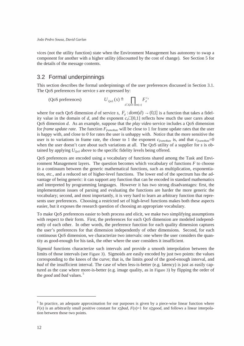
Sigmoid functions characterize such intervals and provide a smooth interpolation between the limits of those intervals (see Figure 3). Sigmoids are easily encoded by just two points: the values corresponding to the knees of the curve; that is, the limits good of the good-enough interval, and bad of the insufficient interval. The case of when less-is-better (e.g. latency) is just as easily cap-tured as the case where more-is-better (e.g. image quality, as in Figure 3) by flipping the order of the good and bad values. 5
5 In practice, an adequate approximation for our purposes is given by a piece-wise linear function where F(x) is an arbitrarily small positive constant for x
�bad, F(x)=1 for x� good, and follows a linear interpola-
tion between those two points.

Aura Software Architecture
13
Figure 3. Generic sigmoid shape
For discrete QoS dimensions, for instance audio fidelity, with values high, medium and low, we simply use a discrete mapping (table) to the utility interval [0,1]. In the case studies we evaluated so far, we found the expressiveness of the forms above to be satisfactory.
The utility of the supplier assignment for a set a of requested services is:
(supplier preferences) ∏∈
⋅⋅=as
cs
xs
cwSupp
ssw FhFaU ˆ)(
where ]1,0(: →timeFw is a function that takes the warm-up time and reflects how much the user is willing to wait for the suppliers to be set up; the exponent cw∈[0,1] reflects how much the user cares about the warm-up time; for each service s in the set a, ]1,0()(: →sSuppFs is a function that appraises the choice for the supplier for s; and the exponent cs∈[0,1] reflects how much the user cares about the assignment of a particular supplier type for that service. Note that discrimi-nating the supplier type, e.g. a preference of MSWord over Notepad for the text editing service, is a compact representation for the preferences with respect to the availability of desired features, such as spell checking or richness of editing capabilities, and to the user’s familiarity with the way those features are offered. Naturally, all the Fs are discrete mappings.
The overall warm-up time of each supplier assignment is calculated by the Environment Man-agement, and Fw will penalize the supplier assignments with warm-ups that the user perceives as long. A typical form for Fw is a sigmoid on the warm-up time. The term hs∈(0,1] reflects how (un)happy the user will be if the supplier for service s is exchanged during use: a value close to 1 means that the user is fine with the change, the closer the value is to zero, the less happy the user will be. The exponent xs indicates whether such change penalty should be considered (xs=1 if the supplier for s is being exchanged by virtue of dynamic change in the environment) or not (xs=0 if the supplier is being newly added or replaced at the user’s request).
The utility of the possible alternatives to support a task t is:
(configuration preferences) ha∈[0,1]
where a∈config(t) is a set of services than can support the user’s task t, and the term ha reflects how happy the user is with the alternative a. As an example, for the task of reviewing a promo-tional video, the user may signal that he is happy dictating the notes, ok with writing them, and will not accept typing them, by setting hvideo&dictate=1, hvideo&write=0.5 and hvideo&type=0.
Given a set of requested services a, and preferences UQoS and USupp as above, the Environment Management determines the optimal supplier assignment sp̂ , and the fidelity points df̂ at which each supplier should run, by finding:
(EM) ( ) ∏ ∏∈ ∈∈
∈∈
��������⋅⋅⋅
aspQoSprofresources
dsQoSd
cds
cs
xss
as
cw
ddomfsSuppp
s
dssw
d
s
fFpFhpWF)(,
)dim()()(
)()()(maxmaxarg
1
good 0
bad
badgood
xbadgood
e
xF−
−+
+=
2
1
1)(
good
-eno
ugh
in
suffi
cien
t

João Pedro Sousa, David Garlan
14
constrained by the QoS profile of each possible supplier ps, and by the available resources in the environment. Note that under the assumption that the suppliers to be added can be activated in parallel, the overall warm-up time is the maximum of the warm-ups for each supplier W(ps). The utility returned to the Task Management is the estimated utility offered by the optimal set of sup-pliers once they are up and running (without the penalty for supplier exchange or warm-up time):
(budget) ∏ ∏∈ ∈
⋅=as
dsQoSd
cds
cs fFpFaU ds )ˆ()ˆ()(ˆ
)dim(
The Task Management decides which set of services a should be ultimately marshaled from the environment to support task t by maximizing:
(TM) )(ˆmaxarg)(
aUhatconfiga
⋅∈
Periodically, the Environment Management evaluates the utility of the configuration at the fidel-ity df actually being provided by the marshaled set of suppliers sp , and compares it with the utility of what would be the currently optimal configuration, sp̂ running at df̂ , discounted by the cost of change and warm-up time. Specifically, the Environment Management will consider a reconfiguration if the inequality below evaluates to true:
∏ ∏∏ ∏∈ ∈∈∈ ∈
��������⋅⋅⋅
������
<��������⋅
= aspQoSprof
resourcesd
sQoSd
cds
cs
xss
as
cw
asd
sQoSd
cds
cs
s
dss
sx
wds fFpFhpWFfFpF
)ˆ(
,)dim()dim(
)ˆ()ˆ()(max)()(1
4 Connectors & Components The previous sections described the layered view of the Aura infrastructure. Specifically, we dis-cussed the responsibilities of the two proposed layers, Task Management and Environment Man-agement, and presented a framework for representing and exploiting user preferences in the con-text of automatic (re)configuration.
In this section we describe the components and connectors of the infrastructure, and we formally specify the protocols of interaction between such components. For the sake of research scope, we focus on the case of a single user; that is, we will not consider issues of coordinating the tasks of multiple users, or of reconciling conflicting user preferences. Additionally, we assume that at a given time and location, the user interacts with a single instance of the infrastructure.6
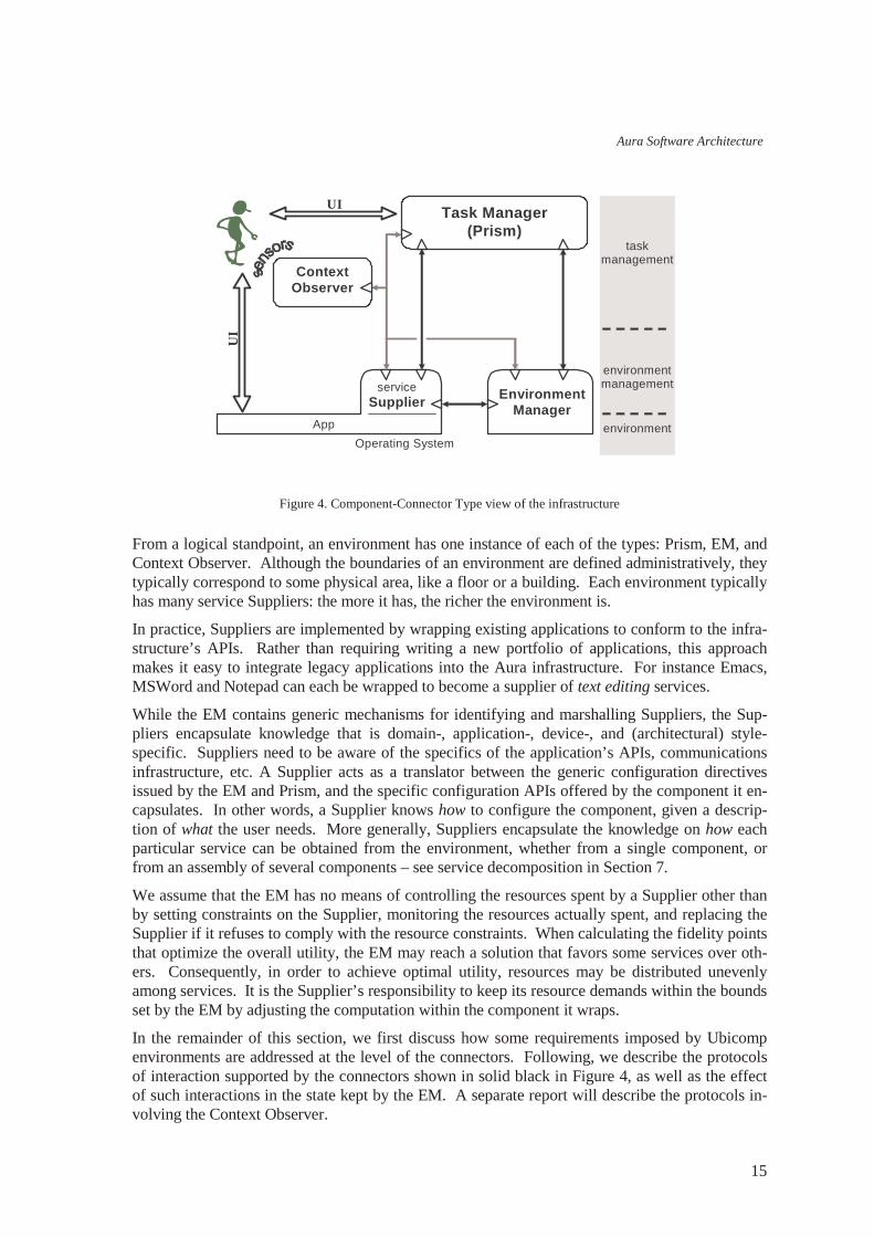
Figure 4 shows a component-connector type view of the infrastructure superimposed on the lay-ers introduced in Figure 2. There are four component types: first, the Task Manager, called Prism, acts as a user proxy, coordinating the automatic configuration and reconfiguration of the envi-ronment. Second, the Context Observer provides information on the physical context surround-ing the user, and reports relevant events in the physical context back to Prism, the Environment Manager, and context-aware applications. Third, the Environment Manager (EM) offers the mechanisms to marshal the supply of services required by user tasks. And fourth, Suppliers pro-vide the abstract services that tasks are composed of: text editing, video playing, etc.
6 Suppose that, for autonomy purposes, the user carries around a laptop with an instance of the infrastruc-ture. When the user enters a location containing another instance of the infrastructure, say his office, pre-sumably the user will expect the two infrastructures to cooperate so that he can access all the capabilities seamlessly. For the time being, and for simplicity sake, we are not addressing such cooperation.
Aura Software Architecture
15
Figure 4. Component-Connector Type view of the infrastructure
From a logical standpoint, an environment has one instance of each of the types: Prism, EM, and Context Observer. Although the boundaries of an environment are defined administratively, they typically correspond to some physical area, like a floor or a building. Each environment typically has many service Suppliers: the more it has, the richer the environment is.
In practice, Suppliers are implemented by wrapping existing applications to conform to the infra-structure’s APIs. Rather than requiring writing a new portfolio of applications, this approach makes it easy to integrate legacy applications into the Aura infrastructure. For instance Emacs, MSWord and Notepad can each be wrapped to become a supplier of text editing services.
While the EM contains generic mechanisms for identifying and marshalling Suppliers, the Sup-pliers encapsulate knowledge that is domain-, application-, device-, and (architectural) style-specific. Suppliers need to be aware of the specifics of the application’s APIs, communications infrastructure, etc. A Supplier acts as a translator between the generic configuration directives issued by the EM and Prism, and the specific configuration APIs offered by the component it en-capsulates. In other words, a Supplier knows how to configure the component, given a descrip-tion of what the user needs. More generally, Suppliers encapsulate the knowledge on how each particular service can be obtained from the environment, whether from a single component, or from an assembly of several components – see service decomposition in Section 7.
We assume that the EM has no means of controlling the resources spent by a Supplier other than by setting constraints on the Supplier, monitoring the resources actually spent, and replacing the Supplier if it refuses to comply with the resource constraints. When calculating the fidelity points that optimize the overall utility, the EM may reach a solution that favors some services over oth-ers. Consequently, in order to achieve optimal utility, resources may be distributed unevenly among services. It is the Supplier’s responsibility to keep its resource demands within the bounds set by the EM by adjusting the computation within the component it wraps.
In the remainder of this section, we first discuss how some requirements imposed by Ubicomp environments are addressed at the level of the connectors. Following, we describe the protocols of interaction supported by the connectors shown in solid black in Figure 4, as well as the effect of such interactions in the state kept by the EM. A separate report will describe the protocols in-volving the Context Observer.
Operating System
Task Manager (Prism)
service Supplier
App
Environment Manager
Context Observer
environment
environment management
task management
UI
UI
João Pedro Sousa, David Garlan
16
4.1 Fiber of the connectors The connectors between the components shown in Figure 4 play an important role in addressing the characteristics of Ubicomp environments. Typical Ubicomp environments are heavily dis-tributed – the Suppliers, especially, may be scattered across different devices, some of which may be remote to the user’s location. Connectivity varies widely, from high-speed wired connections to fluctuating wireless (radio or infrared) connections. Moreover, heterogeneity of devices and software components is a given. Even among the components of the infrastructure, each has to be ready to communicate with different versions of the others. These characteristics impose con-straints on the communication style supported by the connectors. Specifically, this section dis-cusses constraints with respect to the synchronicity of communication and to the format of the exchanged information.
Asynchronous, peer-to-peer communication. In synchronous communication, the originating (calling) component blocks on the reply of the target (called) component. However, in Aura, each component should keep up with its responsibilities in real-time, doing the best it can with the available information, and without blocking on another component’s reply. For example, the EM should not stop monitoring the capabilities of the environment, or replying to Prism’s re-quests, on account of being blocked on the reply of a remote supplier – which may have become disconnected. Likewise, Prism should not stop responding to changes in the user’s task, when waiting for the reply of some other component.
Therefore, all communication between Prism, the Context Observer, the EM, and the Suppliers is asynchronous (non-blocking). By the same token, when any of the components generates a piece of information that is relevant for the others, it has the ability to communicate it immediately without having to wait for a request. For instance, when Prism first wants to instantiate a task, it will request the EM to find the best match of capabilities in the environment. However, if later the environment changes in a way that justifies a reconfiguration, the EM takes the initiative of coming back to Prism suggesting the reconfiguration, or just informing Prism that it performed the reconfiguration.
XML-based tagged format. Tagged formats have the advantage over raw data formats that they make it easier to deal with heterogeneity. Specifically, tagged descriptions of user tasks can be processed by components with different degrees of sophistication. For example, suppose the user requires a text editing service, and would prefer spell checking to be activated. Although finding a suitable Supplier in a rich environment will not be a problem, a basic text editor on a small plat-form may not support spell checking, or even be aware of what “spell checking” means. There-fore, the description of the required service must be such that a given Supplier is able to extract the information it can recognize, without being thrown off by information it does not know how to handle.
A prerequisite for tagged formats to address this problem is that Suppliers of a given service type share a vocabulary of tags and the corresponding interpretation. In the example, a tag for the “spell checking” feature would have to be agreed upon, and hold an unambiguous meaning. Naturally, each service type is characterized by a distinct vocabulary of tags corresponding to the information relevant for the service, although there may exist commonalities across service types. A similar argument applies to all communication between Prism, the EM, etc. Given the dynamic nature of these environments, any component may have to deal with different versions of the other components at some point in time, therefore all communication among the components shown in Figure 4 is XML-based.

Aura Software Architecture
17
The remainder of this section describes the protocols of interaction between Prism and the EM, between Prism and Suppliers, and between the EM and Suppliers – and how those interactions affect the state kept by the EM [9].
4.2 Prism – EM Protocol
Figure 5. Event sequence diagram for the communication between Prism and the EM
The interaction between Prism and the EM is structured around the notion of task session. Prism initiates a session for task A whenever the user starts working on task A, and closes the session whenever the user interrupts or finishes working on that task. Figure 5 shows an event sequence diagram that illustrates a typical task session.7 Prism starts a task session by sending the EM a newTask message. The EM reply, cr eat edTask , includes an id for the task session that will be attached to the exchanged messages throughout the session. Note that many sessions between Prism and the EM may be active concurrently, for one or more users. The session is terminated by a di sband message issued by Prism, to which the EM replies with a t askGone message.
Once a session is started, Prism obtains estimates for the utility that the environment can offer for the user’s task by sending budget messages to the EM. Since there may be alternative configu-rations of services to support a given task, Prism will send one budget message for each of those candidate configurations. For example, for taking notes, either text editing or speech recognition services may be used. To each budget request, the EM replies with a t askLayout . For each service requested within a budget , the t askLayout indicates the Supplier that best matches the
7 The interactions between the EM and Suppliers are elided for simplicity. Note that Suppliers register a description of the services they offer with the EM. More on this in Section 4.5.
r egi s t er <sDes c>
newTas k
c r eat edTask <i d>
budget <i d, t Desc >
t askLay out <i d, cDesc>
set up <i d, t Desc >
t askLay out <i d, cDesc>
. . .
. . .
(re)configure the environment...
t askLay out <i d, cDesc>
set up <i d, t Desc >
t askLay out <i d, cDesc>
. . .
reconfigure the environment...
change
change
����� ��� � � �������������
( )
t askGone <i d>
di sband <i d>
reconfigure the environment...
João Pedro Sousa, David Garlan
18
request among those currently available in the environment, as well as the Quality of Service (QoS) achievable with the current resources. The t askLayout also indicates the overall utility for the configuration (see Section 5 for details). A budgeting exchange is also initiated by Prism whenever there are changes in the user’s context or intent that justify a reevaluation of alternative configurations for the same task.
After evaluating the candidate configurations against the environment’s capabilities, Prism de-cides (possibly with user involvement) which services to set up, and issues a corresponding set up message to the EM. Once the services are set up in the environment (see Section 4.5), the EM replies with a t askLayout containing the up-to-date description of the configuration sup-porting those services. Note that since there is a time lag between a budget and the set up, there may be some differences in what is achievable in the environment. Ideally, the contents of the two corresponding t askLayout messages will be the same, but Prism must be prepared to dou-ble check that, and either accept the differences, or if they are too significant, look for other alter-natives and request a reconfiguration.
Of course, the capabilities of the environment may change, for better or for worse, during a task session. For example, a Supplier involved in the activated configuration may fail or become dis-connected; a new Supplier that is a better match for a requested service may become available; or the resource conditions may change so much, that a different choice of Suppliers with distinct resource demands may be preferable. It is up to the EM to monitor the environment and promptly detect such situations. The EM will then reexamine the best match for the requested services, and it will either carry out the reconfiguration autonomously, or issue a t askLayout message to Prism containing a reconfiguration suggestion (establishing the policies for taking this decision is discussed in Section 3.1). Upon receiving a t askLayout , Prism may wish to study other alter-natives to support the task, which it can do by issuing budget messages, but it will eventually settle on a reconfiguration and send the corresponding set up message.
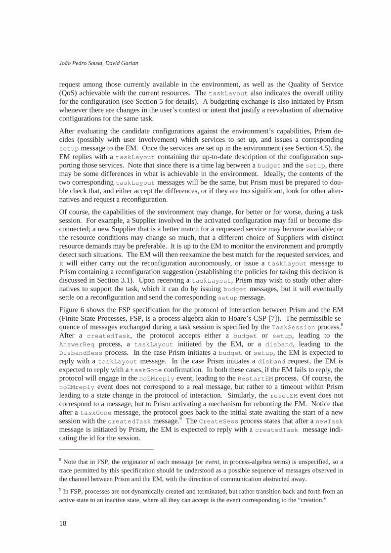
Figure 6 shows the FSP specification for the protocol of interaction between Prism and the EM (Finite State Processes, FSP, is a process algebra akin to Hoare’s CSP [7]). The permissible se-quence of messages exchanged during a task session is specified by the TaskSessi on process.8 After a cr eat edTask , the protocol accepts either a budget or set up, leading to the Answer Req process, a t askLayout initiated by the EM, or a di sband, leading to the Di sbandSess process. In the case Prism initiates a budget or set up, the EM is expected to reply with a t askLayout message. In the case Prism initiates a di sband request, the EM is expected to reply with a t askGone confirmation. In both these cases, if the EM fails to reply, the protocol will engage in the noEMr epl y event, leading to the Rest ar t EM process. Of course, the noEMr epl y event does not correspond to a real message, but rather to a timeout within Prism leading to a state change in the protocol of interaction. Similarly, the r eset EM event does not correspond to a message, but to Prism activating a mechanism for rebooting the EM. Notice that after a t askGone message, the protocol goes back to the initial state awaiting the start of a new session with the cr eat edTask message.9 The Cr eat eSess process states that after a newTask message is initiated by Prism, the EM is expected to reply with a cr eat edTask message indi-cating the id for the session.
8 Note that in FSP, the originator of each message (or event, in process-algebra terms) is unspecified, so a trace permitted by this specification should be understood as a possible sequence of messages observed in the channel between Prism and the EM, with the direction of communication abstracted away.
9 In FSP, processes are not dynamically created and terminated, but rather transition back and forth from an active state to an inactive state, where all they can accept is the event corresponding to the “creation.”
Aura Software Architecture
19
Figure 6. FSP specification for the connector Prism-EM
The Prism-EM protocol is given by the parallel composition of the process for creating new ses-sions, Cr eat eSess , and of some arbitrary number of processes of type TaskSessi on. In the FSP specification, this arbitrary number of processes of the same type is achieved by prefixing the process (and consequently the events within that process) by a label (t ) and a number (i d, in the arbitrary range TI d). The process Cr eat eSess and each specific t [ i d] . TaskSessi on process interact by sharing the event t [ i d] . cr eat edTask – this models a new task session be-ing created and named. Furthermore, all t [ i d] . TaskSessi on processes share the noEMr epl y and r eset EM events making sure all task sessions agree on when the EM needs to be restarted. This synchronization in the process model is achieved by relabeling all t [ i d] . noEMr epl y events to a single event noEMr epl y , and the same for r eset EM.
4.3 Prism – Suppliers Protocol
Figure 7. Event sequence diagram for the communication between Prism and the Suppliers
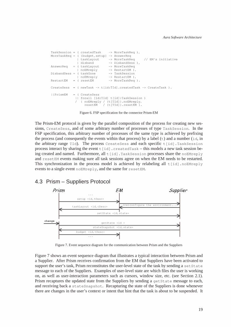
Figure 7 shows an event sequence diagram that illustrates a typical interaction between Prism and a Supplier. After Prism receives confirmation from the EM that Suppliers have been activated to support the user’s task, Prism reconstitutes the user-level state of the task by sending a set St at e message to each of the Suppliers. Examples of user-level state are which files the user is working on, as well as user-interaction parameters such as cursors, window size, etc. (see Section 2.1). Prism recaptures the updated state from the Suppliers by sending a get St at e message to each, and receiving back a st at eSnapshot . Recapturing the state of the Suppliers is done whenever there are changes in the user’s context or intent that hint that the task is about to be suspended. It
TaskSessi on = ( cr eat edTask - > Mor eTaskReq ) , Mor eTaskReq = ( { budget , set up} - > Answer Req | t askLayout - > Mor eTaskReq / / EM' s i ni t i at i ve | di sband - > Di sbandSess ) , Answer Req = ( t askLayout - > Mor eTaskReq | noEMr epl y - > Rest ar t EM ) , Di sbandSess = ( t askGone - > TaskSessi on | noEMr epl y - > Rest ar t EM ) , Rest ar t EM = ( r eset EM - > Mor eTaskReq ) . Cr eat eSess = ( newTask - > t [ i d: TI d] . cr eat edTask - > Cr eat eTask ) . | | Pr i smEM = ( Cr eat eSess | | f or al l [ i d: TI d] t [ i d] : TaskSessi on ) / { noEMr epl y / { t [ TI d] } . noEMr epl y, r eset EM / { t [ TI d] } . r eset EM } .
set St at e <i d, s t at e>
set up <i d, t Desc>
t askLayout <i d, cDesc>
. . .
(re)configure the environment...
budget <i d, t Desc>
change
����� ��� � � �������������
get St at e <i d >
s t at eSnapshot <i d, s t at e>
. . .

João Pedro Sousa, David Garlan
20
may also be done periodically, to ensure recovery of an almost up-to-date state in the case a Sup-plier fails.
Figure 8. FSP specification for the connector Prism-Suppliers
Figure 8 shows the FSP specification for the protocol of interaction between Prism and the Sup-pliers. For each task session, the protocol admits any sequence of set St at e and get St at e messages, with the proviso that a st at eSnapshot reply is expected after each get St at e. Similarly to the noEMr epl y event in the Prism-EM connector, noSuppRepl y corresponds to a timeout within Prism rather than to an exchanged message. In this case, however, Prism will not take any action to recover/restart the Supplier. Prism relies on the EM to diagnose and propose the replacement of faulty Suppliers. Therefore, Prism will wait for some indication from the EM, or otherwise try to get the state again. The following section addresses combining these two pro-tocols within Prism.
4.4 Prism
Figure 9. FSP specification for the behavior of Prism
Figure 9 shows the FSP specification for the behavior of Prism. That behavior is the parallel composition of the process for creating new sessions, I nvokeTask , of an arbitrary number of task session interactions with the EM, Task , and of the same number of interactions with Suppli-ers, UseSupp. The processes I nvokeTask and Task state Prism’s view of the processes Cr eat eSess and TaskSessi on, respectively, in the Prism-EM protocols (they are restated here
| | Pr i smSuppl i er = f or al l [ i d: TI d] t [ i d] : Set Get St at e. Set Get St at e = ( set St at e - > Set Get St at e | get St at e - > ( st at eSnapshot - > Set Get St at e | noSuppRepl y - > Set Get St at e ) ) .
| | Pr i sm = ( I nvokeTask | | f or al l [ i d: TI d] t [ i d] : Task | | f or al l [ i d: TI d] t [ i d] : UseSupp ) / { noEMr epl y / { t [ TI d] } . noEMr epl y, r eset EM / { t [ TI d] } . r eset EM } . I nvokeTask = ( newTask - > t [ i d: TI d] . cr eat edTask - > I nvokeTask ) . Task = ( cr eat edTask - > Cr eat edTask ) , Cr eat edTask = ( { budget , set up} - > Get Layout | t askLayout - > Cr eat edTask / / EM' s i ni t i at i ve | di sband - > Di sbandTask ) , Get Layout = ( t askLayout - > Cr eat edTask | noEMr epl y - > Rest ar t EM ) , Di sbandTask = ( t askGone - > Task | noEMr epl y - > Rest ar t EM ) , Rest ar t EM = ( r eset EM - > Cr eat edTask ) . UseSupp = ( set up - > Set St at e | { t askLayout , noEMr epl y, di sband} - > UseSupp ) , Set St at e = ( t askLayout - > set St at e - > Set Get St at e | noEMr epl y - > UseSupp ) , Set Get St at e = ( { set St at e, get St at e, noEMr epl y} - > Set Get St at e | t askLayout - > ( r epl aceSuppl i er - > UseSupp | keepSuppl i er - > Set Get St at e ) | set up - > Set St at e | di sband - > UseSupp ) \ { keepSuppl i er , r epl aceSuppl i er } .

Aura Software Architecture
21
for completeness of the specification of Prism’s behavior). Notice also that, as before, the events noEMr epl y and r eset EM are shared among the processes for all task sessions.
The glue between the two protocols Prism-EM and Prism-Supplier is specified by the UseSupp process. For simplicity, the messages exchanged with all the Suppliers supporting one user’s task are modeled as single events. For instance, the set St at e event corresponds to sending set St at e messages to all such Suppliers. The central rule governing this protocol is that after receiving a t askLayout in response to a set up, the state of the Suppliers must be set. There-fore, initially, the UseSupp process looks for set up events and is permissive to other messages – for instance, t askLayout may occur is response to a budget. After the set up event, the Set St at e process looks for the corresponding t askLayout , after which it issues a set Sat e, or in case the EM fails to respond, it resets to UseSupp. After the initial set St at e, the Set Get St at e process allows Prism to issue any number of set St at e and get St at e messages. However, if a t askLayout is received at this stage, it will correspond to the EM’s initiative to substitute a Supplier. In such a case, Prism must decide whether to keep the supplier or to request a replacement by issuing a set up (in UseSupp). Notice that both keepSupl i er and r epl aceSuppl i er are local events just for the purpose of modeling Prism’s decision. Addi-tionally, as a consequence of a change in user intent, Prism may decide to request a change in the configuration by issuing a set up and waiting for the corresponding t askLayout (in Set -St at e). Naturally, disbanding the task session resets the process to its initial state.
4.5 Protocol EM – Suppliers
Figure 10. Event sequence diagram for the communication between the EM and the Suppliers
Figure 10 shows an event sequence diagram that illustrates a typical interaction between the EM and a Supplier. After the EM receives a set up request from Prism, it activates the Supplier, indicating the bounds on resource consumption, and it attaches the Supplier’s ports as requested in the set up message. Both the act i vat e and at t ach messages are acknowledged by the Supplier upon successful completion. After the supplier is activated, it issues periodic QoS re-ports to the EM. If the resources in the environment change significantly, the EM may establish new resource bounds for the Supplier by sending it an adj ust message with the new bounds. Eventually, the EM will receive a disband message from Prism and proceeds to deactivate the Supplier. Notice that the EM makes sure the Supplier is up and properly attached before return-
set up <i d, t Des c>
t askLayout <i d, c Desc>
. . .
����� ��� � � �������������
ac t i vat e <i d, r esBnds>
at t ach <i d, conn>
ackAct i vat e <i d>
ack At t ach <i d>
QoSr epor t <i d, QoS>
. . .
di sband <i d> deac t i vat e <i d>
t askGone <i d>
adj us t <i d, r esBnds>
. . .
change
João Pedro Sousa, David Garlan
22
ing a t askLayout to Prism. Subsequent adjustments to resource bounds and deactivation are not subject to the same constraint, and therefore, acknowledgments are not required.
Figure 11. FSP specification for the connector EM-Suppliers
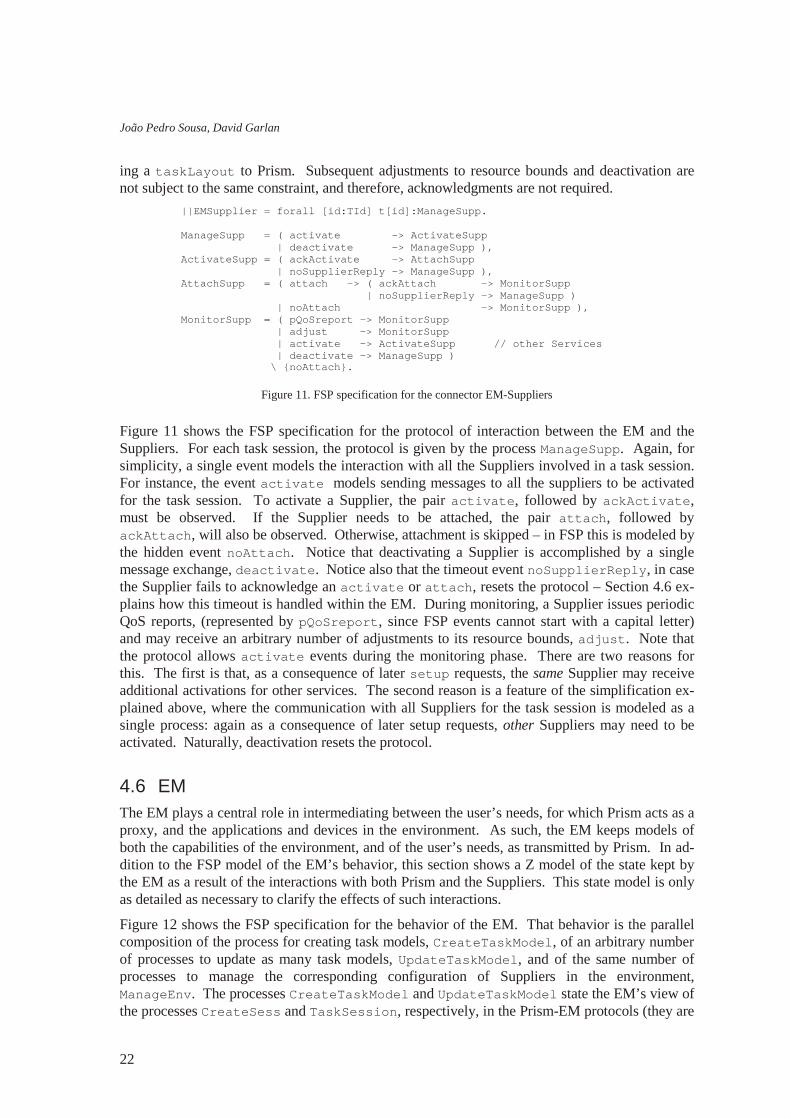
Figure 11 shows the FSP specification for the protocol of interaction between the EM and the Suppliers. For each task session, the protocol is given by the process ManageSupp. Again, for simplicity, a single event models the interaction with all the Suppliers involved in a task session. For instance, the event act i vat e models sending messages to all the suppliers to be activated for the task session. To activate a Supplier, the pair act i vat e, followed by ackAct i vat e, must be observed. If the Supplier needs to be attached, the pair at t ach, followed by ackAt t ach, will also be observed. Otherwise, attachment is skipped – in FSP this is modeled by the hidden event noAt t ach. Notice that deactivating a Supplier is accomplished by a single message exchange, deact i vat e. Notice also that the timeout event noSuppl i er Repl y , in case the Supplier fails to acknowledge an act i vat e or at t ach, resets the protocol – Section 4.6 ex-plains how this timeout is handled within the EM. During monitoring, a Supplier issues periodic QoS reports, (represented by pQoSr epor t , since FSP events cannot start with a capital letter) and may receive an arbitrary number of adjustments to its resource bounds, adj ust . Note that the protocol allows act i vat e events during the monitoring phase. There are two reasons for this. The first is that, as a consequence of later set up requests, the same Supplier may receive additional activations for other services. The second reason is a feature of the simplification ex-plained above, where the communication with all Suppliers for the task session is modeled as a single process: again as a consequence of later setup requests, other Suppliers may need to be activated. Naturally, deactivation resets the protocol.
4.6 EM The EM plays a central role in intermediating between the user’s needs, for which Prism acts as a proxy, and the applications and devices in the environment. As such, the EM keeps models of both the capabilities of the environment, and of the user’s needs, as transmitted by Prism. In ad-dition to the FSP model of the EM’s behavior, this section shows a Z model of the state kept by the EM as a result of the interactions with both Prism and the Suppliers. This state model is only as detailed as necessary to clarify the effects of such interactions.
Figure 12 shows the FSP specification for the behavior of the EM. That behavior is the parallel composition of the process for creating task models, Cr eat eTaskModel , of an arbitrary number of processes to update as many task models, Updat eTaskModel , and of the same number of processes to manage the corresponding configuration of Suppliers in the environment, ManageEnv . The processes Cr eat eTaskModel and Updat eTaskModel state the EM’s view of the processes Cr eat eSess and TaskSessi on, respectively, in the Prism-EM protocols (they are
| | EMSuppl i er = f or al l [ i d: TI d] t [ i d] : ManageSupp. ManageSupp = ( act i vat e - > Act i vat eSupp | deact i vat e - > ManageSupp ) , Act i vat eSupp = ( ackAct i vat e - > At t achSupp | noSuppl i er Repl y - > ManageSupp ) , At t achSupp = ( at t ach - > ( ackAt t ach - > Moni t or Supp | noSuppl i er Repl y - > ManageSupp ) | noAt t ach - > Moni t or Supp ) , Moni t or Supp = ( pQoSr epor t - > Moni t or Supp | adj ust - > Moni t or Supp | act i vat e - > Act i vat eSupp / / ot her Ser vi ces | deact i vat e - > ManageSupp ) \ { noAt t ach} .

Aura Software Architecture
23
restated here for completeness of the specification of EM’s behavior). Notice that the noEMr epl y event is not seen by the EM since it corresponds to a timeout within Prism. Notice also that the observation of the event mi ssQoSr epor t s prompts the EM to issue a t askLayout with a reconfiguration suggestion to Prism (more on this below).
Figure 12. FSP specification for behavior of the EM
The glue between the two protocols Prism-EM and EM-Supplier is specified by the ManageEnv process. As before, for simplicity, the messages exchanged with all the Suppliers supporting one task are modeled as single events. For instance, the act i vat e event corresponds to sending act i vat e messages to all such Suppliers. The implementation of the EM can use standard con-currency mechanisms, such as barriers, to wait for the reception of all the relevant acknowledge messages, and only then, from the protocol specification point of view, consider that it observed the corresponding ackAct i vat e event. The activation and attachment of Suppliers is triggered upon receiving a set up request. In the case all the acknowledgements are received, that is, upon the successful activation and attachment of the requested Suppliers, the EM issues a t askLayout with the complete configuration. In the case some of the acknowledgements time-out, the event nosuppl i er Repl y is observed, and a t askLayout is still issued but this time with a possibly incomplete configuration. In this latter case, the EM may try to find and activate alternative, possibly less optimal Suppliers before returning the t askLayout . Notice that a set up may request some of the Suppliers in the current configuration to be deactivated (see Act i vat eSupp process). No acknowledgment is needed for deactivation before issuing the up-dated t askLayout .
| | EM = ( Cr eat eTaskModel | | f or al l [ i d: TI d] t [ i d] : Updat eTaskModel | | f or al l [ i d: TI d] t [ i d] : ManageEnv ) / { r eset EM / { t [ TI d] } . r eset EM } . Cr eat eTaskModel = ( newTask - > t [ i d: TI d] . cr eat edTask - > Cr eat eTaskModel ) . Updat eTaskModel = ( cr eat edTask - > Cr eat edTaskModel ) , Cr eat edTaskModel = ( { budget , set up} - > I ssueLayout | mi ssQoSRepor t s - > I ssueLayout / / EM i ni t i at i ve | r eset EM - > Cr eat edTaskModel | di sband - > RemoveTaskModel ) , I ssueLayout = ( t askLayout - > Cr eat edTaskModel | r eset EM - > Cr eat edTaskModel ) , RemoveTaskModel = ( t askGone - > Updat eTaskModel | r eset EM - > Cr eat edTaskModel ) . ManageEnv = ( set up - > Act i vat eSupp | pQoSr epor t - > deact i vat e - > ManageEnv | r eset EM - > ManageEnv ) , Act i vat eSupp = ( act i vat e - > ( ackAct i vat e - > At t achSupp | noSuppl i er Repl y - > I ssueLayout ) | deact i vat e - > I ssueLayout | r eset EM - > ManageEnv ) , At t achSupp = ( at t ach - > ( ackAt t ach - > I ssueLayout | noSuppl i er Repl y - > I ssueLayout ) | ski pAt t ach - > I ssueLayout | r eset EM - > ManageEnv ) , I ssueLayout = ( t askLayout - > Moni t or Supp | r eset EM - > ManageEnv ) , Moni t or Supp = ( adj ust - > Moni t or Supp | pQoSr epor t - > Moni t or Supp | mi ssQoSRepor t s - > I ssueLayout / / r epor t t o Pr i sm | r eset EM - > Moni t or Supp | set up - > Act i vat eSupp | di sband - > deact i vat e - > { t askGone, r eset EM} - > ManageEnv ) \ { ski pAt t ach} .
João Pedro Sousa, David Garlan
24
After the first set up for a task session, the EM monitors the configuration according to the Moni t or Supp process. Active Suppliers in a configuration periodically issue QoS reports to the EM. The EM uses these reports to evaluate the utility of the current set of suppliers against pos-sible alternatives in the environment and may come up with an advantageous reconfiguration. Furthermore, when the EM notices that a particular Supplier fails to issue QoS reports, it will try to replace that (presumably) faulty Supplier: in the FSP model this is represented by the event mi ssQoSr epor t s , leading to the I ssueLayout process. In either case, and according to the autonomy policies for swapping Suppliers (refer to Section 3.1), the EM may have to confirm with Prism that the reconfiguration is appropriate/opportune before carrying out. Nonetheless, the EM has full autonomy to adj ust the resource bounds on the Suppliers.
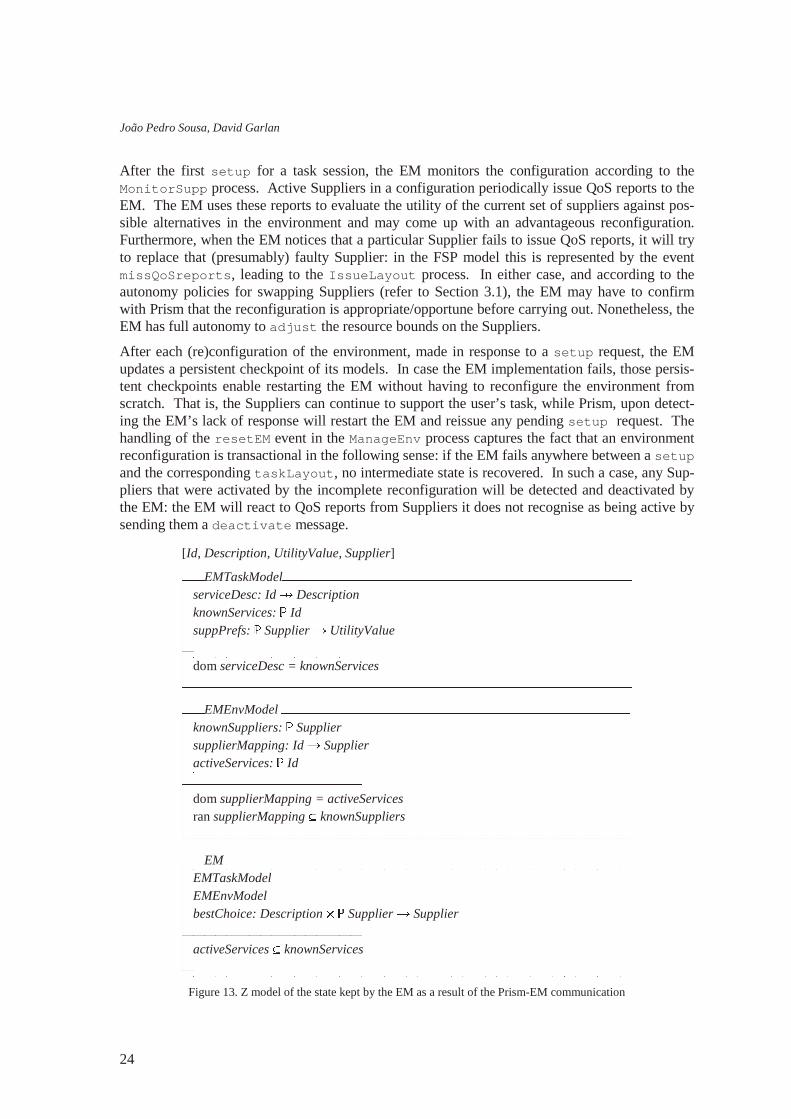
After each (re)configuration of the environment, made in response to a set up request, the EM updates a persistent checkpoint of its models. In case the EM implementation fails, those persis-tent checkpoints enable restarting the EM without having to reconfigure the environment from scratch. That is, the Suppliers can continue to support the user’s task, while Prism, upon detect-ing the EM’s lack of response will restart the EM and reissue any pending set up request. The handling of the r eset EM event in the ManageEnv process captures the fact that an environment reconfiguration is transactional in the following sense: if the EM fails anywhere between a set up and the corresponding t askLayout , no intermediate state is recovered. In such a case, any Sup-pliers that were activated by the incomplete reconfiguration will be detected and deactivated by the EM: the EM will react to QoS reports from Suppliers it does not recognise as being active by sending them a deact i vat e message.
Figure 13. Z model of the state kept by the EM as a result of the Prism-EM communication
[Id, Description, UtilityValue, Supplier]
��� EMTaskModel ��������������������������������������������������������������serviceDesc: Id � Description �knownServices: � Id �suppPrefs: � Supplier � UtilityValue �������������������������������dom serviceDesc = knownServices �����������������������������������������������������������������������������
��� EMEnvModel ��������������������������������������������������������������knownSuppliers: � Supplier �supplierMapping: Id � Supplier �activeServices: � Id �������������������������������dom supplierMapping = activeServices �ran supplierMapping knownSuppliers �����������������������������������������������������������������������������
��� EM ������������������������������������������������������������������������EMTaskModel �EMEnvModel �bestChoice: Description � � Supplier � Supplier �������������������������������activeServices knownServices �����������������������������������������������������������������������������
Aura Software Architecture
25
Figure 14. Z model of the effect of the r egi st er message on the state kept by the EM
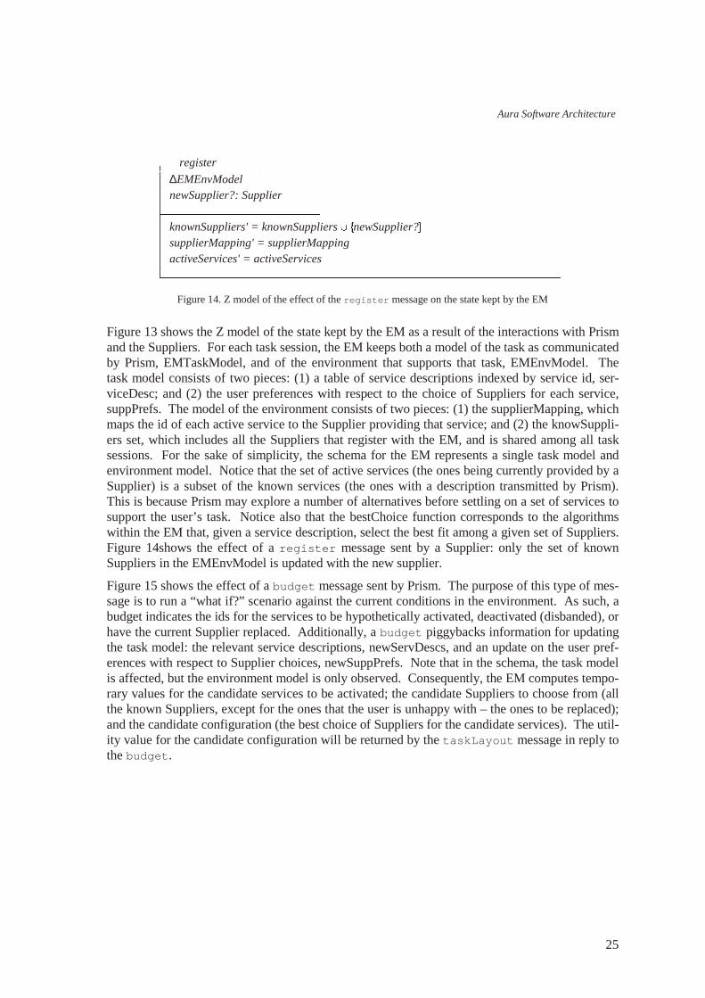
Figure 13 shows the Z model of the state kept by the EM as a result of the interactions with Prism and the Suppliers. For each task session, the EM keeps both a model of the task as communicated by Prism, EMTaskModel, and of the environment that supports that task, EMEnvModel. The task model consists of two pieces: (1) a table of service descriptions indexed by service id, ser-viceDesc; and (2) the user preferences with respect to the choice of Suppliers for each service, suppPrefs. The model of the environment consists of two pieces: (1) the supplierMapping, which maps the id of each active service to the Supplier providing that service; and (2) the knowSuppli-ers set, which includes all the Suppliers that register with the EM, and is shared among all task sessions. For the sake of simplicity, the schema for the EM represents a single task model and environment model. Notice that the set of active services (the ones being currently provided by a Supplier) is a subset of the known services (the ones with a description transmitted by Prism). This is because Prism may explore a number of alternatives before settling on a set of services to support the user’s task. Notice also that the bestChoice function corresponds to the algorithms within the EM that, given a service description, select the best fit among a given set of Suppliers. Figure 14shows the effect of a r egi st er message sent by a Supplier: only the set of known Suppliers in the EMEnvModel is updated with the new supplier.
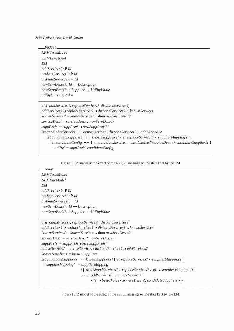
Figure 15 shows the effect of a budget message sent by Prism. The purpose of this type of mes-sage is to run a “what if?” scenario against the current conditions in the environment. As such, a budget indicates the ids for the services to be hypothetically activated, deactivated (disbanded), or have the current Supplier replaced. Additionally, a budget piggybacks information for updating the task model: the relevant service descriptions, newServDescs, and an update on the user pref-erences with respect to Supplier choices, newSuppPrefs. Note that in the schema, the task model is affected, but the environment model is only observed. Consequently, the EM computes tempo-rary values for the candidate services to be activated; the candidate Suppliers to choose from (all the known Suppliers, except for the ones that the user is unhappy with – the ones to be replaced); and the candidate configuration (the best choice of Suppliers for the candidate services). The util-ity value for the candidate configuration will be returned by the t askLayout message in reply to the budget .
��� register ��������������������������������������������������������������������∆EMEnvModel �newSupplier?: Supplier �������������������������������knownSuppliers' = knownSuppliers �
�newSupplier?��
supplierMapping' = supplierMapping �activeServices' = activeServices �����������������������������������������������������������������������������
João Pedro Sousa, David Garlan
26
Figure 15. Z model of the effect of the budget message on the state kept by the EM
Figure 16. Z model of the effect of the set up message on the state kept by the EM
��� budget ��������������������������������������������������������������������������������������������∆EMTaskModel �ΞEMEnvModel �EM �addServices?: � Id �replaceServices?: � Id �disbandServices?: � Id �newServDescs?: Id � Description �newSuppPrefs?: � Supplier � UtilityValue �utility!: UtilityValue �������������������������������disj
�addServices?� replaceServices?� disbandServices?��
addServices? � replaceServices? � disbandServices? knownServices' �knownServices' = knownServices � dom newServDescs? �serviceDesc' = serviceDesc � newServDescs? �suppPrefs' = suppPrefs � newSuppPrefs? �let candidateServices ��� activeServices \ disbandServices? � addServices? � � let candidateSuppliers ��� knownSuppliers \
�s: replaceServices? � supplierMapping s ��
� let candidateConfig ��� �
s: candidateServices � bestChoice ���
serviceDesc s� � candidateSuppliers� �� � utility! = suppPrefs' candidateConfig �����������������������������������������������������������������������������������������������������
��� setup����������������������������������������������������������������������������������������������∆EMTaskModel �∆EMEnvModel �EM �addServices?: � Id �replaceServices?: � Id �disbandServices?: � Id �newServDescs?: Id � Description �newSuppPrefs?: � Supplier � UtilityValue �������������������������������disj
�addServices?� replaceServices?� disbandServices?��
addServices? � replaceServices? � disbandServices? knownServices' �knownServices' = knownServices � dom newServDescs? �serviceDesc' = serviceDesc � newServDescs? �suppPrefs' = suppPrefs � newSuppPrefs? �activeServices' = activeServices \ disbandServices? � addServices? �knownSuppliers' = knownSuppliers �let candidateSuppliers ��� knownSuppliers \
�s: replaceServices? � supplierMapping s ��
� supplierMapping' = supplierMapping � \
�d: disbandServices? � replaceServices? � �
d � supplierMapping d� �� �
�s: addServices? � replaceServices? �
� �s � bestChoice
���serviceDesc s� � candidateSuppliers��� �
�����������������������������������������������������������������������������������������������������
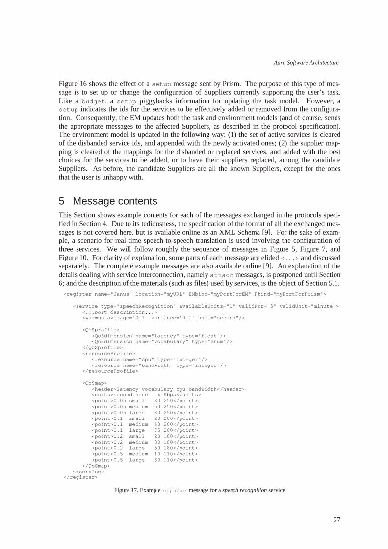
Aura Software Architecture
27
Figure 16 shows the effect of a set up message sent by Prism. The purpose of this type of mes-sage is to set up or change the configuration of Suppliers currently supporting the user’s task. Like a budget , a set up piggybacks information for updating the task model. However, a set up indicates the ids for the services to be effectively added or removed from the configura-tion. Consequently, the EM updates both the task and environment models (and of course, sends the appropriate messages to the affected Suppliers, as described in the protocol specification). The environment model is updated in the following way: (1) the set of active services is cleared of the disbanded service ids, and appended with the newly activated ones; (2) the supplier map-ping is cleared of the mappings for the disbanded or replaced services, and added with the best choices for the services to be added, or to have their suppliers replaced, among the candidate Suppliers. As before, the candidate Suppliers are all the known Suppliers, except for the ones that the user is unhappy with.
5 Message contents This Section shows example contents for each of the messages exchanged in the protocols speci-fied in Section 4. Due to its tediousness, the specification of the format of all the exchanged mes-sages is not covered here, but is available online as an XML Schema [9]. For the sake of exam-ple, a scenario for real-time speech-to-speech translation is used involving the configuration of three services. We will follow roughly the sequence of messages in Figure 5, Figure 7, and Figure 10. For clarity of explanation, some parts of each message are elided <. . . > and discussed separately. The complete example messages are also available online [9]. An explanation of the details dealing with service interconnection, namely at t ach messages, is postponed until Section 6; and the description of the materials (such as files) used by services, is the object of Section 5.1.
Figure 17. Example r egi st er message for a speech recognition service
<r egi st er name=" Janus" l ocat i on=" myURL" EMbi nd=" myPortForEM" Pbi nd=" myPortForPrism" > <ser vi ce t ype=" speechRecogni t i on" avai l abl eUni t s=" 1" val i dFor =" 5" val i dUni t =" mi nut e" > <. . . por t descr i pt i on. . . > <war mup aver age=" 0. 1" var i ance=" 0. 1" uni t =" second" / > <QoSpr of i l e> <QoSdi mensi on name=" l at ency" t ype=" f l oat " / > <QoSdi mensi on name=" vocabul ar y" t ype=" enum" / > </ QoSpr of i l e> <r esour cePr of i l e> <r esour ce name=" cpu" t ype=" i nt eger " / > <r esour ce name=" bandwi dt h" t ype=" i nt eger " / > </ r esour cePr of i l e> <QoSmap> <header >l at ency vocabul ar y cpu bandwi dt h</ header > <uni t s>second none % Kbps</ uni t s> <poi nt >0. 05 smal l 30 250</ poi nt > <poi nt >0. 05 medi um 50 250</ poi nt > <poi nt >0. 05 l ar ge 80 250</ poi nt > <poi nt >0. 1 smal l 20 200</ poi nt > <poi nt >0. 1 medi um 40 200</ poi nt > <poi nt >0. 1 l ar ge 75 200</ poi nt > <poi nt >0. 2 smal l 20 180</ poi nt > <poi nt >0. 2 medi um 30 180</ poi nt > <poi nt >0. 2 l ar ge 50 180</ poi nt > <poi nt >0. 5 medi um 10 110</ poi nt > <poi nt >0. 5 l ar ge 30 110</ poi nt > </ QoSmap> </ ser vi ce> </ r egi st er >

João Pedro Sousa, David Garlan
28
Figure 17 shows an example r egi st er message issued by the Janus speech recognizer. The at-tributes in the main element are the name, to which the user refers in the supplier preferences; the network l ocat i on of the Supplier (either an IP address or an URL); and two TCP ports where the Supplier is listening for messages coming in from the EM, EMbi nd, and from Prism, Pbi nd. A registration message contains one or more service announcements, which include the service t ype, and the number of available units. Typically, suppliers based on shareable software and devices will have several, or unbound, available units, while suppliers that involve non-shareable devices, such as sound input or output devices, have at most one unit available at any given time. The announcement validity attributes offer the EM a concrete criterion for the renovation of the registry of availability (see the EMEnvModel in Section 4.6). The body of a service announce-ment contains a description of the ports for service interconnection (see Section 6); an estimate for the warm-up time;10 and the QoS characteristics of the Supplier. The latter include the QoS profile, which enumerates the QoS dimensions for the service; the resource profile, which enu-merates the resources that the Supplier monitors and to which it adapts; and the QoS map, which maps a discrete set of typical fidelity points to the corresponding resource demands. During nor-mal operation, the Supplier is responsible for benchmarking the component it wraps, and updat-ing the information used to generate the QoS map – this is the same mechanism on which the pe-riodic QoS reports are based (see Figure 26).
Figure 18. Example session-framing messages for the speech-to-speech scenario
Figure 18 show example framing messages for a task session: newTask issued by Prism to create a new task; the corresponding EM reply, which includes the EM-generated t askI d; down to the closing di sband, and corresponding acknowledgment, t askGone.
Figure 19 shows example budget and set up messages. The allowed contents for these two messages are exactly the same – refer to Section 4.6 for a discussion of the interpretation and ef-fects of each of these messages. The contents of these messages have three parts: first, a change element enumerates one or more operations to be performed on the elements of the task. These operations correspond to the addServices, replaceServices and disbandServices parameters in Figure 15 and Figure 16. Whereas for simplicity, Section 4.6 referred only to services, in general the elements requested to support a task are services, connections (see Section 6), and materials (see Section 5.1); each with a unique i d within the task, and each described at some point in ei-ther a budget or set up message. The possible operations for the task elements are: add and di sband, applicable to any task element, and r epl ace, for services alone. Second, budget and set up messages piggyback zero or more descriptions for the relevant task elements: this corre-sponds to parameter newServDescs in Section 4.6. Third, both types of messages may carry an excerpt of supplier preferences – corresponding to the newSuppPrefs parameter. Notice that each message doesn’ t have to carry the complete supplier preferences because these, like the descrip-tions for task elements, are updated by functional overwriting.
10 The average time that the Supplier needs to prepare for normal operation after receiving an act i vat e. This corresponds to the term W(ps) – or W(Janus), in this case – discussed in Section 3.2.
<newTask/ > <cr eat edTask t askI d=" 34" / > <di sband t askI d=" 34" / > <t askGone t askI d=" 34" / >

Aura Software Architecture
29
Figure 19. Example budget and set up messages for the speech-to-speech scenario
Service descriptions carry an i d, which is local to the task, the t ype of service, and the attribute changeSuppl i er states whether the Environment Management has the autonomy to swap the supplying component as soon as a new one comes along with a higher utility (see Section 3.1). The ser vi ce element also contains a description for the required ports, and the QoS preferences for the service (see below).
Figure 20. Example QoS preferences for the speech recognition service
Figure 20 shows the QoS preferences for the speech recognition service in the example in Figure 19. Preferences are expressed for two QoS dimensions: the latency associated with the recogni-
<budget t askI d=" 34" > <change> <ser vi ce i d=" 1" op=" add" / > <ser vi ce i d=" 2" op=" add" / > <ser vi ce i d=" 3" op=" add" / > </ change> <ser vi ce i d=" 1" t ype=" speechRecogni t i on" changeSuppl i er =" ask" > <. . . por t descr i pt i on. . . > <. . . QoS pr ef er ences. . . > </ ser vi ce> <ser vi ce i d=" 2" t ype=" l anguageTr ansl at i on" changeSuppl i er =" goAhead" > <. . . por t descr i pt i on. . . > <. . . QoS pr ef er ences. . . > </ ser vi ce> <ser vi ce i d=" 3" t ype=" speechSynt hesi s" changeSuppl i er =" ask" > <. . . por t descr i pt i on. . . > <. . . QoS pr ef er ences. . . > </ ser vi ce> <. . . suppl i er pr ef er ences. . . > </ budget > <set up t askI d=" 34" > <change> <ser vi ce i d=" 1" op=" add" / > <ser vi ce i d=" 2" op=" add" / > </ change> <. . . ser vi ce/ mat er i al descr i pt i ons. . . > <. . . suppl i er pr ef er ences. . . > </ set up>
<ut i l i t y combi ne=" pr oduct " > <QoSdi mensi on name=" l at ency" t ype=" f l oat " > <f unct i on t ype=" si gmoi d" wei ght =" 1" > <t hr eshol ds good=" 0. 1" bad=" 2" uni t =" second" / > </ f unct i on> </ QoSdi mensi on> <QoSdi mensi on name=" vocabul ar y" t ype=" enum" > <f unct i on t ype=" t abl e" wei ght =" 0. 5" > <ent r y x=" l ar ge" f _x=" 1" / > <ent r y x=" medi um" f _x=" 0. 95" / > <ent r y x=" smal l " f _x=" 0. 2" / > </ f unct i on> </ QoSdi mensi on> <cont ext At t name=" di st anceToUser " t ype=" i nt " > <f unct i on t ype=" si gmoi d" wei ght =" 1" > <t hr eshol ds good=" 3" bad=" 10" uni t =" met er " / > </ f unct i on> </ cont ext At t > </ ut i l i t y>

João Pedro Sousa, David Garlan
30
tion of each utterance, and the size of the vocabulary that can be recognized (the more terms are searched, the more resource-demanding is the recognition). The function Flatency is a sigmoid where the value over which the user is clearly unhappy with the response, bad, is 2 seconds, and the value under which the user does not perceive the delay as an issue, good, is 0.1 seconds (see Section 3.2). The function Fvocabulary is a table that expresses that the user is happy with a large vocabulary, mostly happy with a medium vocabulary, and not so happy with a small vocabulary. The attributes wei ght in each of the two f unct i on elements correspond to clatency and cvocabulary, respectively. A context attribute, distance to user, is shown to illustrate that preferences with re-spect to context attributes that pertain to the service can be expressed in the same way as QoS preferences (a separate report will cover Context Observation).
Figure 21. Example supplier preferences for the speech-to-speech scenario
Figure 21 shows the supplier preferences for the example in Figure 19, specifically for the ser-vices with id 1 and 2, as well as the warm-up term for the configuration. These elements corre-spond to the terms Fs, specifically FspeechRecognition and FlanguageTranslation, and Fw, respectively, in Sec-tion 3.2. The entry with x=" change" under the function for each service s corresponds to the term hs. In the example, the user will be happy if the language translator is exchanged, hlan-
guageTranslation=1, but not if the speech recognizer is exchanged, hspeechRecognition=0.1. The user prefer-ences with respect to the warm-up time are expressed as a sigmoid, where the wei ght attribute corresponds to cw.
Figure 22. Example t askLayout message for the speech-to-speech scenario
<ut i l i t y combi ne=" pr oduct " > <suppl i er i d=" 1" > <f unct i on t ype=" t abl e" wei ght =" 1" > <ent r y x=" Janus" f _x=" 1" / > <ent r y x=" Sphi nx" f _x=" 1" / > <ent r y x=" ot her " f _x=" 0. 001" / > <ent r y x=" change" f _x=" 0. 1" / > </ f unct i on> </ suppl i er > <suppl i er i d=" 2" > <f unct i on t ype=" t abl e" wei ght =" 0. 5" > <ent r y x=" Babel Fi sh" f _x=" 1" / > <ent r y x=" ot her " f _x=" 0. 5" / > <ent r y x=" change" f _x=" 1" / > </ f unct i on> </ suppl i er > <war mup> <f unct i on t ype=" si gmoi d" wei ght =" 1" > <t hr eshol ds good=" 0. 1" bad=" 2" uni t =" second" / > </ f unct i on> </ war mup> </ ut i l i t y>
<t askLayout t askI d=" 34" utility="0.85"> <ser vi ce i d=" 1" op=" added" > <suppl i er name=" Janus" l ocat i on=" SR-IPaddr" bi nd=" SR-PortForPrism" / > <. . . est i mat ed QoS. . . > </ ser vi ce> <ser vi ce i d=" 2" op=" added" > <suppl i er name=" Babel Fi sh" l ocat i on=" LT-IPaddr" bi nd=" LT-PortForPrism" / > <. . . est i mat ed QoS. . . > </ ser vi ce> </ t askLayout >
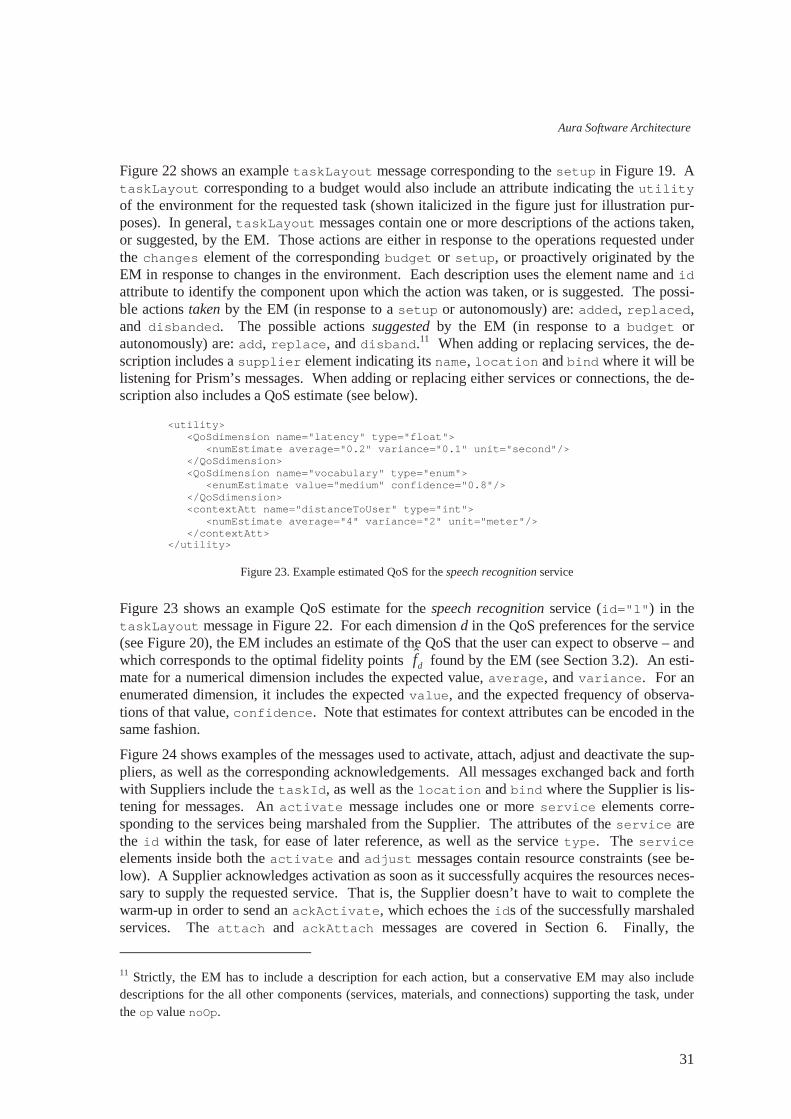
Aura Software Architecture
31
Figure 22 shows an example t askLayout message corresponding to the set up in Figure 19. A t askLayout corresponding to a budget would also include an attribute indicating the ut i l i t y of the environment for the requested task (shown italicized in the figure just for illustration pur-poses). In general, t askLayout messages contain one or more descriptions of the actions taken, or suggested, by the EM. Those actions are either in response to the operations requested under the changes element of the corresponding budget or set up, or proactively originated by the EM in response to changes in the environment. Each description uses the element name and i d attribute to identify the component upon which the action was taken, or is suggested. The possi-ble actions taken by the EM (in response to a set up or autonomously) are: added, r epl aced, and di sbanded. The possible actions suggested by the EM (in response to a budget or autonomously) are: add, r epl ace, and di sband.11 When adding or replacing services, the de-scription includes a suppl i er element indicating its name, l ocat i on and bi nd where it will be listening for Prism’s messages. When adding or replacing either services or connections, the de-scription also includes a QoS estimate (see below).
Figure 23. Example estimated QoS for the speech recognition service
Figure 23 shows an example QoS estimate for the speech recognition service (i d=" 1" ) in the t askLayout message in Figure 22. For each dimension d in the QoS preferences for the service (see Figure 20), the EM includes an estimate of the QoS that the user can expect to observe – and which corresponds to the optimal fidelity points df̂ found by the EM (see Section 3.2). An esti-mate for a numerical dimension includes the expected value, aver age, and var i ance. For an enumerated dimension, it includes the expected val ue, and the expected frequency of observa-tions of that value, conf i dence. Note that estimates for context attributes can be encoded in the same fashion.
Figure 24 shows examples of the messages used to activate, attach, adjust and deactivate the sup-pliers, as well as the corresponding acknowledgements. All messages exchanged back and forth with Suppliers include the t askI d, as well as the l ocat i on and bi nd where the Supplier is lis-tening for messages. An act i vat e message includes one or more ser vi ce elements corre-sponding to the services being marshaled from the Supplier. The attributes of the ser vi ce are the i d within the task, for ease of later reference, as well as the service t ype. The ser vi ce elements inside both the act i vat e and adj ust messages contain resource constraints (see be-low). A Supplier acknowledges activation as soon as it successfully acquires the resources neces-sary to supply the requested service. That is, the Supplier doesn’ t have to wait to complete the warm-up in order to send an ackAct i vat e, which echoes the i ds of the successfully marshaled services. The at t ach and ackAt t ach messages are covered in Section 6. Finally, the
11 Strictly, the EM has to include a description for each action, but a conservative EM may also include descriptions for the all other components (services, materials, and connections) supporting the task, under the op value noOp.
<ut i l i t y> <QoSdi mensi on name=" l at ency" t ype=" f l oat " > <numEst i mat e aver age=" 0. 2" var i ance=" 0. 1" uni t =" second" / > </ QoSdi mensi on> <QoSdi mensi on name=" vocabul ar y" t ype=" enum" > <enumEst i mat e val ue=" medi um" conf i dence=" 0. 8" / > </ QoSdi mensi on> <cont ext At t name=" di st anceToUser " t ype=" i nt " > <numEst i mat e aver age=" 4" var i ance=" 2" uni t =" met er " / > </ cont ext At t > </ ut i l i t y>

João Pedro Sousa, David Garlan
32
deact i vat e message lists the services (identified by i d) to be deactivated, among those cur-rently marshaled from the target Supplier for task t askI d.
Figure 24. Example supplier-configuration messages for the speech-to-speech scenario
Figure 25. Example resource constraints for the speech recognition service
Figure 25 shows the resource constraints included in the act i vat e for the speech recognition service in Figure 24. These constraints are obtained by the EM when calculating the optimal fi-delity points (see Figure 23), taking into account the relationship between the two, as expressed in the service registration (see the QoS map in Figure 17). A constraint is issued for each resource in the resource profile of the service, with the same form as the estimates for the QoS: typically, numeric estimates with an aver age, a var i ance, and a uni t ; or an enumerated estimate with a val ue, and a conf i dence.
Figure 26 shows an example QoS report issued by the Supplier for the speech recognition service after the activation shown in Figure 24. Like other messages exchanged with the Suppliers, QoSr epor t indicates the corresponding t askI d, as well as the l ocat i on and bi nd where the Supplier is listening for messages. A QoSr epor t includes a report for one or more services (as many as being supplied by the Supplier for the task at hand) identified by the service i d. Each report has the same format as the QoS estimate in Figure 23, but its contents reflect the actual values of the QoS being offered to the user, as monitored by the Supplier.
<act i vat e t askI d=" 34" l ocat i on=" SR-IPaddr" bi nd=" SR-PortForEM" > <ser vi ce i d=" 1" t ype=" speechRecogni t i on" > <. . . r esour ce const r ai nt s. . . > </ ser vi ce> </ act i vat e> <ackAct i vat e t askI d=" 34" l ocat i on=" SR-IPaddr" bi nd=" SR-PortForEM" > <ser vi ce i d=" 1" / > </ ackAct i vat e> <at t ach t askI d=" 34" l ocat i on=" SR-IPaddr" bi nd=" SR-PortForEM" > <. . . connect i on descr i pt i on. . . > </ at t ach> <ackAt t ach t askI d=" 34" l ocat i on=" SR-IPaddr" bi nd=" SR-PortForEM" > <. . . connect i on conf i r mat i on. . . > </ ackAt t ach> <adj ust t askI d=" 34" l ocat i on=" SR-IPaddr" bi nd=" SR-PortForEM" > <ser vi ce i d=" 1" > <. . . r esour ce const r ai nt s. . . > </ ser vi ce> </ adj ust > <deact i vat e t askI d=" 34" l ocat i on=" SR-IPaddr" bi nd=" SR-PortForEM" > <ser vi ce i d=" 1" / > </ deact i vat e>
<const r ai nt s> <r esour ce name=" cpu" t ype=" i nt eger " > <numEst i mat e aver age=" 30" var i ance=" 10" uni t =" %" / > </ r esour ce> <r esour ce name=" bandwi dt h" t ype=" i nt eger " > <numEst i mat e aver age=" 180" var i ance=" 40" uni t =" Kbps" / > </ r esour ce> </ const r ai nt s>
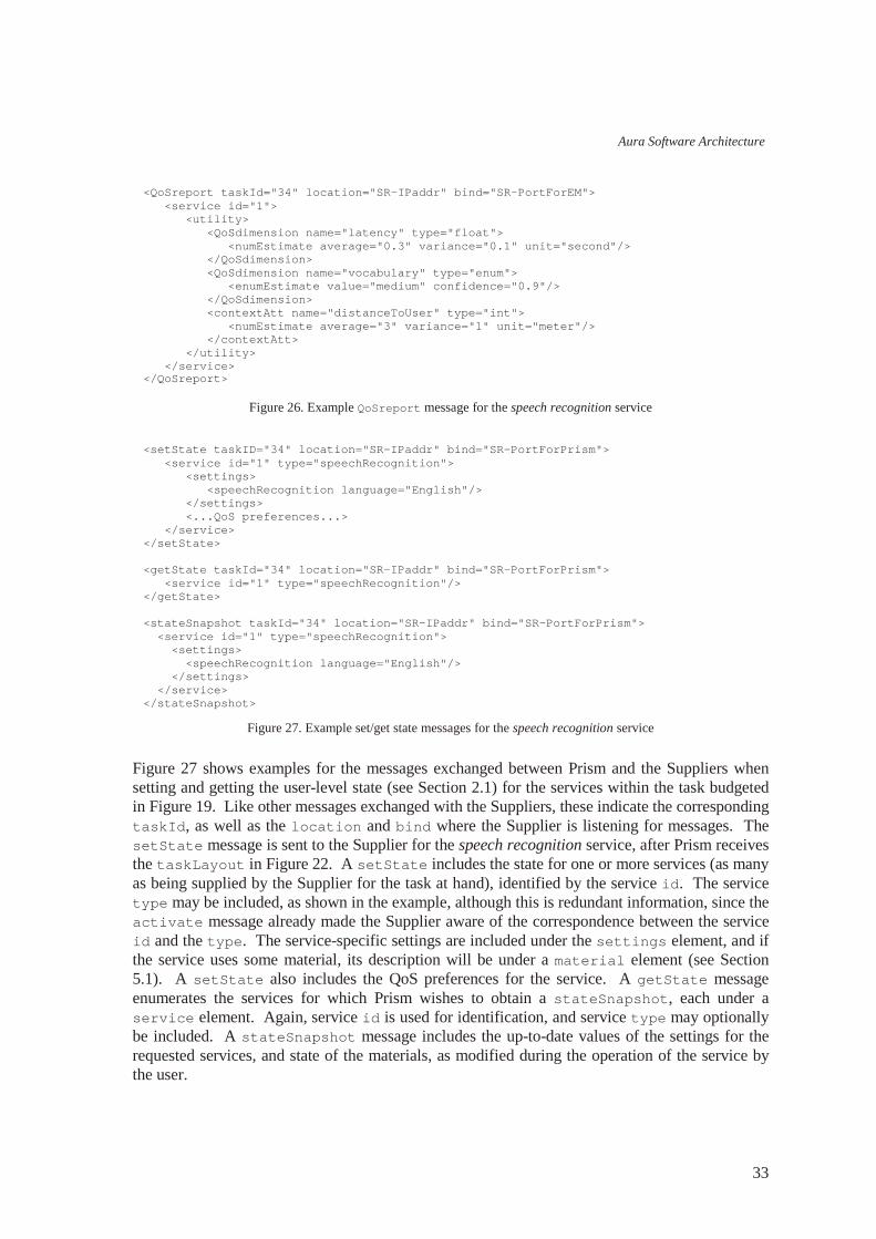
Aura Software Architecture
33
Figure 26. Example QoSr epor t message for the speech recognition service
Figure 27. Example set/get state messages for the speech recognition service
Figure 27 shows examples for the messages exchanged between Prism and the Suppliers when setting and getting the user-level state (see Section 2.1) for the services within the task budgeted in Figure 19. Like other messages exchanged with the Suppliers, these indicate the corresponding t askI d, as well as the l ocat i on and bi nd where the Supplier is listening for messages. The set St at e message is sent to the Supplier for the speech recognition service, after Prism receives the t askLayout in Figure 22. A set St at e includes the state for one or more services (as many as being supplied by the Supplier for the task at hand), identified by the service i d. The service t ype may be included, as shown in the example, although this is redundant information, since the act i vat e message already made the Supplier aware of the correspondence between the service i d and the t ype. The service-specific settings are included under the set t i ngs element, and if the service uses some material, its description will be under a mat er i al element (see Section 5.1). A set St at e also includes the QoS preferences for the service. A get St at e message enumerates the services for which Prism wishes to obtain a st at eSnapshot , each under a ser vi ce element. Again, service i d is used for identification, and service t ype may optionally be included. A st at eSnapshot message includes the up-to-date values of the settings for the requested services, and state of the materials, as modified during the operation of the service by the user.
<QoSr epor t t askI d=" 34" l ocat i on=" SR-IPaddr" bi nd=" SR-PortForEM" > <ser vi ce i d=" 1" > <ut i l i t y> <QoSdi mensi on name=" l at ency" t ype=" f l oat " > <numEst i mat e aver age=" 0. 3" var i ance=" 0. 1" uni t =" second" / > </ QoSdi mensi on> <QoSdi mensi on name=" vocabul ar y" t ype=" enum" > <enumEst i mat e val ue=" medi um" conf i dence=" 0. 9" / > </ QoSdi mensi on> <cont ext At t name=" di st anceToUser " t ype=" i nt " > <numEst i mat e aver age=" 3" var i ance=" 1" uni t =" met er " / > </ cont ext At t > </ ut i l i t y> </ ser vi ce> </ QoSr epor t >
<set St at e t askI D=" 34" l ocat i on=" SR-IPaddr" bi nd=" SR-PortForPrism" > <ser vi ce i d=" 1" t ype=" speechRecogni t i on" > <set t i ngs> <speechRecogni t i on l anguage=" Engl i sh" / > </ set t i ngs> <. . . QoS pr ef er ences. . . > </ ser vi ce> </ set St at e> <get St at e t askI d=" 34" l ocat i on=" SR-IPaddr" bi nd=" SR-PortForPrism" > <ser vi ce i d=" 1" t ype=" speechRecogni t i on" / > </ get St at e> <st at eSnapshot t askI d=" 34" l ocat i on=" SR-IPaddr" bi nd=" SR-PortForPrism" > <ser vi ce i d=" 1" t ype=" speechRecogni t i on" > <set t i ngs> <speechRecogni t i on l anguage=" Engl i sh" / > </ set t i ngs> </ ser vi ce> </ st at eSnapshot >
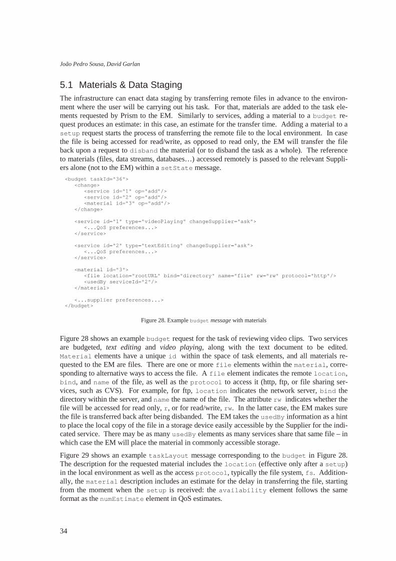
João Pedro Sousa, David Garlan
34
5.1 Materials & Data Staging The infrastructure can enact data staging by transferring remote files in advance to the environ-ment where the user will be carrying out his task. For that, materials are added to the task ele-ments requested by Prism to the EM. Similarly to services, adding a material to a budget re-quest produces an estimate: in this case, an estimate for the transfer time. Adding a material to a set up request starts the process of transferring the remote file to the local environment. In case the file is being accessed for read/write, as opposed to read only, the EM will transfer the file back upon a request to di sband the material (or to disband the task as a whole). The reference to materials (files, data streams, databases…) accessed remotely is passed to the relevant Suppli-ers alone (not to the EM) within a set St at e message.
Figure 28. Example budget message with materials
Figure 28 shows an example budget request for the task of reviewing video clips. Two services are budgeted, text editing and video playing, along with the text document to be edited. Mat er i al elements have a unique i d within the space of task elements, and all materials re-quested to the EM are files. There are one or more f i l e elements within the mat er i al , corre-sponding to alternative ways to access the file. A f i l e element indicates the remote l ocat i on, bi nd, and name of the file, as well as the pr ot ocol to access it (http, ftp, or file sharing ser-vices, such as CVS). For example, for ftp, l ocat i on indicates the network server, bi nd the directory within the server, and name the name of the file. The attribute r w indicates whether the file will be accessed for read only, r , or for read/write, r w. In the latter case, the EM makes sure the file is transferred back after being disbanded. The EM takes the usedBy information as a hint to place the local copy of the file in a storage device easily accessible by the Supplier for the indi-cated service. There may be as many usedBy elements as many services share that same file – in which case the EM will place the material in commonly accessible storage.
Figure 29 shows an example t askLayout message corresponding to the budget in Figure 28. The description for the requested material includes the l ocat i on (effective only after a set up) in the local environment as well as the access pr ot ocol , typically the file system, f s . Addition-ally, the mat er i al description includes an estimate for the delay in transferring the file, starting from the moment when the set up is received: the avai l abi l i t y element follows the same format as the numEst i mat e element in QoS estimates.
<budget t askI d=" 36" > <change> <ser vi ce i d=" 1" op=" add" / > <ser vi ce i d=" 2" op=" add" / > <mat er i al i d=" 3" op=" add" / > </ change> <ser vi ce i d=" 1" t ype=" vi deoPl ayi ng" changeSuppl i er =" ask" > <. . . QoS pr ef er ences. . . > </ ser vi ce> <ser vi ce i d=" 2" t ype=" t ext Edi t i ng" changeSuppl i er =" ask" > <. . . QoS pr ef er ences. . . > </ ser vi ce> <mat er i al i d=" 3" > <f i l e l ocat i on=" rootURL" bi nd=" directory" name=" file" r w=" r w" pr ot ocol =" ht t p" / > <usedBy ser vi ceI d=" 2" / > </ mat er i al > <. . . suppl i er pr ef er ences. . . > </ budget >

Aura Software Architecture
35
Figure 29. Example t askLayout message with materials
Figure 30. Example set St at e message for text editing a local file
Figure 31. Example set St at e message for video playing a remote file and a remote stream
Figure 30 shows an example set St at e message for the text editing service, initially budgeted in Figure 28. Note that the ser vi ce element now includes a description for each of the materials being processed by the service. A material description is comprised of, first, the information on how to access the material – in the example, the f i l e element returned by the EM in the t askLayout in Figure 29 – and second, the st at e of the material. Note that the set t i ngs of
<t askLayout t askI d=" 36" ut i l i t y=" 0. 95" > <ser vi ce i d=" 1" op=" add" >. . . </ ser vi ce> <ser vi ce i d=" 2" op=" add" >. . . </ ser vi ce> <mat er i al i d=" 3" op=" add" > <f i l e l ocat i on=" localDirectory" name = pr ot ocol =" f s" / > <avai l abi l i t y aver age=" 10" var i ance=" 5" uni t =" second" / > </ mat er i al > </ t askLayout >
<set St at e t askI D=" 36" l ocat i on=" TE-IPaddr" bi nd=" TE-PortForPrism" > <ser vi ce i d=" 1" t ype=" t ext Edi t i ng" > <set t i ngs> <pane hei ght =" 260" wi dt h=" 200" uni t =" mm" / > <spel l i ng enabl ed=" t r ue" i gnor eAl l Caps=" t r ue" / > <edi t i ng over st r i ke=" f al se" r epl aceSel ect i on=" t r ue" / > </ set t i ngs> <. . . QoS pr ef er ences. . . > <mat er i al i d=" 3" > <f i l e l ocat i on=" localDirectory" pr ot ocol =" f s" / > <st at e> <t ext scr ol l =" 0" zoom=" 100" cur sor =" 15" / > </ st at e> </ mat er i al > </ ser vi ce> </ set St at e>
<set St at e t askI D=" 36" l ocat i on=" VP-IPaddr" bi nd=" VP-PortForPrism" > <ser vi ce i d=" 2" t ype=" vi deoPl ayi ng" > <set t i ngs> <pl ayi ngOpt i ons mul t i pl ePanes=" yes" aut or esi ze=" yes" / > </ set t i ngs> <. . . QoS pr ef er ences. . . > <mat er i al i d=" 4" > <f i l e l ocat i on=" URL" bi nd=" directory" name=" video" f or mat =" mp2" pr ot ocol =" ht t p" / > <f i l e l ocat i on=" URL" bi nd=" directory" name=" video" f or mat =" mp4" pr ot ocol =" ht t p" / > <st at e> <vi deo pl ayi ng=" pause" cur sor =" 00: 01: 15" zoom=" 100" / > <audi o l evel =" 40" mut e=" no" / > </ st at e> </ mat er i al > <mat er i al i d=" 5" > <st r eam l ocat i on=" URL" bi nd=" directory" name=" video" f or mat =" avi " pr ot ocol =" ht t p" / > <st at e> <vi deo pl ayi ng=" pl ay" cur sor =" " zoom=" 200" / > <audi o l evel =" 60" mut e=" no" / > </ st at e> </ mat er i al > </ ser vi ce> </ set St at e>
João Pedro Sousa, David Garlan
36
the service include three groups of settings, applicable to all the materials, and that the state of the material is specific to the file being edited (see Section 2.1).
Figure 31 shows an example set St at e message for the video playing service, initially budgeted in Figure 28. For the sake of example, two materials are being used by this service, both accessed remotely – and therefore, not requested to, and not prefetched by the EM. The first is a remote video file, and the second is a video stream. Note that the location information follows the exact same format used by Prism to request data staging to the EM. However, for remote access, mul-tiple formats can be used to exploit tradeoffs between video quality and bandwidth utilization. The f or mat attributes of f i l e/st r eam, enumerate the available data formats.
6 Interconnecting services Service interconnection is reflected at the three levels of the infrastructure shown in Figure 2. At the Task Management layer, the user describes which services he wants interconnected – and those requirements are propagated down in the budget requests issued by Prism. At the Envi-ronment Management Level, the EM interprets the required interconnections, and upon a set up, issues at t ach messages to the Suppliers of the services to be interconnected (see Section 4.5). Each Supplier uses the communications infrastructure in the environment (networks and middle-ware) according to the specific characteristics of the encapsulated component. The Suppliers at the endpoints of a connection are responsible for gathering monitoring information (see [3]) and report the QoS of the connection back to the EM, piggybacked on their periodic QoS reports.
Descriptions built at the Task Management level reflect the depth of understanding of the user about services and service interconnection, rather than the depth of understanding of a software architect or system’s specialist. For example, in the physical world, to hook up a regular PC the user needs to connect the power outlet to the PC’s power input, using the power cable, the video output to the monitor’s video in, using the video cable, and so on. The user doesn’ t need to be familiar with the pin layout of the video cable, or with the specifications of the electrical signals that go in each pin. In Software Architecture, specifications of connectors can be fairly complex, including the port (interface) signatures, interaction protocols, and so on. In the Aura infrastruc-ture, this depth of knowledge resides at the Environment Management level: the EM accounts for interconnection compatibility, and the Suppliers (and components they wrap) account for the spe-cifics of the interfaces and protocols.
Consequently, the concepts to be captured when describing service interconnection at the Task Management level are distinct from those captured in Architectural Description Languages such as Acme, or their XML-based counterparts, such as xArch [4,5]. The main concept is that of the dynamic establishment of (point-to-point) connections between services. This concept can be used while being oblivious of how that connection will be realized: opening a session on a point-to-point connector, activating a publish-subscribe mechanism over an event bus (multi-point con-nector), etc. Under the premise of leaving the connector-specific knowledge at the Environment Management level, Prism requests connections by identifying the services to be connected and the port types on those services. It is up to each Supplier to decide whether the connection re-quires the use of a dedicated port, or if it can be multiplexed as a new session on a shared port.

Aura Software Architecture
37
Figure 32. Example of a budget with interconnections
Figure 32 shows an example budget request with three interconnected services: speech recogni-tion, (textual) language translation, and speech synthesis. To achieve real-time translation of speech into speech, the speech recognition output is piped to the input of the language translation, whose output is in turn piped into the input of speech synthesis. The notion of connection is added to the budget request, with a format and treatment similar to the notion of service. Like services, connections have an associated type, such as pipe, or RPC; and QoS preferences, with QoS dimensions such as bandwidth and latency.12 The changes element refers to the connec-tions to be added or removed in the same way that it refers to the services to be added or re-moved. The EM uses the type information in port descriptions (see below) and connection re-quests to decide on marshaling and interconnection compatibility. The QoS preferences for the connections are factored into the framework in Section 3.2 by adding the connections to the set a, with the terms corresponding to the supplier preferences set to one.
12 As with service types, distinct connector types typically have a distinct set of QoS dimensions.
<budget t askI d=" 34" > <change> <ser vi ce i d=" 1" op=" add" / > <ser vi ce i d=" 2" op=" add" / > <ser vi ce i d=" 3" op=" add" / > <connect i on i d=" 4" op =" add" / > <connect i on i d=" 5" op =" add" / > </ change> <ser vi ce i d=" 1" t ype=" speechRecogni t i on" changeSuppl i er =" ask" > <por t t ype=" t ext Out " / > <. . . QoS pr ef er ences. . . > </ ser vi ce> <ser vi ce i d=" 2" t ype=" l anguageTr ansl at i on" changeSuppl i er =" goAhead" > <por t t ype=" t ext I n" / > <por t t ype=" t ext Out " / > <. . . QoS pr ef er ences. . . > </ ser vi ce> <ser vi ce i d=" 3" t ype=" speechSynt hesi s" changeSuppl i er =" ask" > <por t t ype=" t ext I n" / > <. . . QoS pr ef er ences. . . > </ ser vi ce> <connect i on i d=" 4" t ype=" pi pe" > <at t ach> <f r om ser vi ceI d=" 1" por t =" t ext Out " / > <t o ser vi ceI d=" 2" por t =" t ext I n" / > </ at t ach> <. . . QoS pr ef er ences. . . > </ connect i on> <connect i on i d=" 5" t ype=" pi pe" > <at t ach> <f r om ser vi ceI d=" 2" por t =" t ext Out " / > <t o ser vi ceI d=" 3" por t =" t ext I n" / > </ at t ach> <. . . QoS pr ef er ences. . . > </ connect i on> <. . . suppl i er pr ef er ences. . . > </ budget >
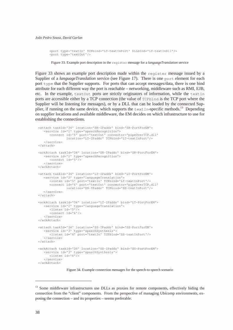
João Pedro Sousa, David Garlan
38
Figure 33. Example port description in the r egi st er message for a languageTranslation service
Figure 33 shows an example port description made within the r egi st er message issued by a Supplier of a languageTranslation service (see Figure 17). There is one por t element for each port t ype that the Supplier supports. For ports that can accept messages/data, there is one bind attribute for each different way the port is reachable – networking, middleware such as RMI, EJB, etc. In the example, t ext Out ports are strictly originators of information, while the t ext I n ports are accessible either by a TCP connection (the value of TCPbi nd is the TCP port where the Supplier will be listening for messages), or by a DLL that can be loaded by the connected Sup-plier, if running on the same device, which supports the t ext I n-specific methods.13 Depending on supplier locations and available middleware, the EM decides on which infrastructure to use for establishing the connections.
Figure 34. Example connection messages for the speech-to-speech scenario
13 Some middleware infrastructures use DLLs as proxies for remote components, effectively hiding the connection from the “client” components. From the perspective of managing Ubicomp environments, ex-posing the connection – and its properties – seems preferable.
<at t ach t askI d=" 34" l ocat i on=" SR-IPaddr" bi nd=" SR-PortForEM" > <ser vi ce i d=" 1" t ype=" speechRecogni t i on" > <connect i d=" 5" por t =" t ext Out " connect or =" pipeOverTCP.dll" l ocat i on=" LT-IPaddr" TCPbi nd=" LT-textInPort" / > </ ser vi ce> </ at t ach> <ackAt t ach t askI d=" 34" l ocat i on=" SR-IPaddr" bi nd=" SR-PortForEM" > <ser vi ce i d=" 1" t ype=" speechRecogni t i on" > <connect i d=" 5" / > </ ser vi ce> </ ackAt t ach> <at t ach t askI d=" 34" l ocat i on=" LT-IPaddr" bi nd=" LT-PortForEM" > <ser vi ce i d=" 2" t ype=" l anguageTr ansl at i on" > <l i st en i d=" 5" por t =" t ext I n" TCPbi nd=" LT-textInPort" / > <connect i d=" 6" por t =" t ext Out " connect or =" pipeOverTCP.dll" l ocat i on=" SS-IPaddr" TCPbi nd=" SS-textInPort" / > </ ser vi ce> </ at t ach> <ackAt t ach t askI d=" 34" l ocat i on=" LT-IPaddr" bi nd=" LT-PortForEM" > <ser vi ce i d=" 2" t ype=" l anguageTr ansl at i on" > <l i st en i d=" 5" / > <connect i d=" 6" / > </ ser vi ce> </ ackAt t ach> <at t ach t askI d=" 34" l ocat i on=" SS-IPaddr" bi nd=" SS-PortForEM" > <ser vi ce i d=" 3" t ype=" speechSynt hesi s" > <l i st en i d=" 6" por t =" t ext I n" TCPbi nd=" SS-textInPort" / > </ ser vi ce> </ at t ach> <ackAt t ach t askI d=" 34" l ocat i on=" SS-IPaddr" bi nd=" SS-PortForEM" > <ser vi ce i d=" 3" t ype=" speechSynt hesi s" > <l i st en i d=" 6" / > </ ser vi ce> </ ackAt t ach>
<por t t ype=" t ext I n" TCPbi nd=" LT-textInPort" DLLbi nd=" LT-textInDll" / > <por t t ype=" t ext Out " / >
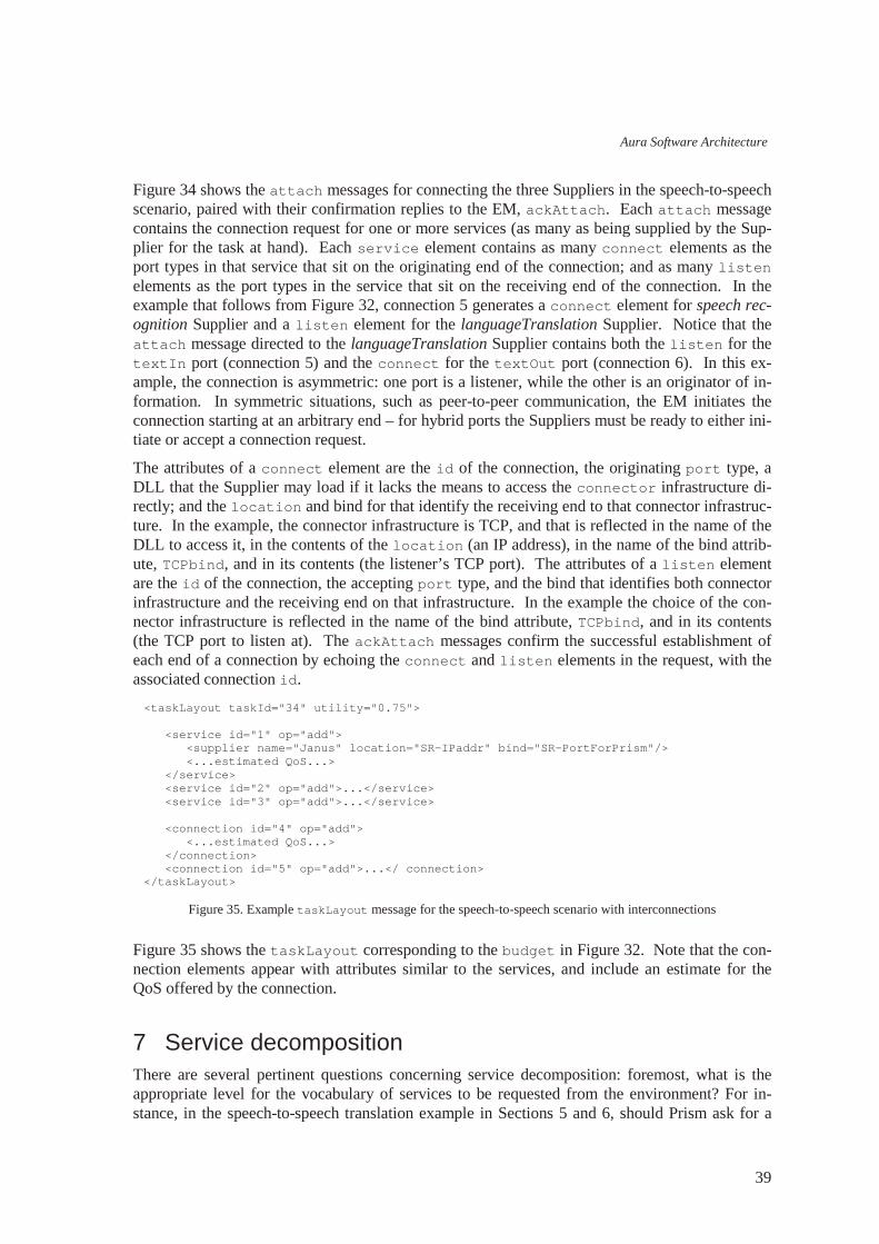
Aura Software Architecture
39
Figure 34 shows the at t ach messages for connecting the three Suppliers in the speech-to-speech scenario, paired with their confirmation replies to the EM, ackAt t ach. Each at t ach message contains the connection request for one or more services (as many as being supplied by the Sup-plier for the task at hand). Each ser vi ce element contains as many connect elements as the port types in that service that sit on the originating end of the connection; and as many l i s t en elements as the port types in the service that sit on the receiving end of the connection. In the example that follows from Figure 32, connection 5 generates a connect element for speech rec-ognition Supplier and a l i s t en element for the languageTranslation Supplier. Notice that the at t ach message directed to the languageTranslation Supplier contains both the l i s t en for the t ext I n port (connection 5) and the connect for the t ext Out port (connection 6). In this ex-ample, the connection is asymmetric: one port is a listener, while the other is an originator of in-formation. In symmetric situations, such as peer-to-peer communication, the EM initiates the connection starting at an arbitrary end – for hybrid ports the Suppliers must be ready to either ini-tiate or accept a connection request.
The attributes of a connect element are the i d of the connection, the originating por t type, a DLL that the Supplier may load if it lacks the means to access the connect or infrastructure di-rectly; and the l ocat i on and bind for that identify the receiving end to that connector infrastruc-ture. In the example, the connector infrastructure is TCP, and that is reflected in the name of the DLL to access it, in the contents of the l ocat i on (an IP address), in the name of the bind attrib-ute, TCPbi nd, and in its contents (the listener’s TCP port). The attributes of a l i s t en element are the i d of the connection, the accepting por t type, and the bind that identifies both connector infrastructure and the receiving end on that infrastructure. In the example the choice of the con-nector infrastructure is reflected in the name of the bind attribute, TCPbi nd, and in its contents (the TCP port to listen at). The ackAt t ach messages confirm the successful establishment of each end of a connection by echoing the connect and l i s t en elements in the request, with the associated connection i d.
Figure 35. Example t askLayout message for the speech-to-speech scenario with interconnections
Figure 35 shows the t askLayout corresponding to the budget in Figure 32. Note that the con-nection elements appear with attributes similar to the services, and include an estimate for the QoS offered by the connection.
7 Service decomposition There are several pertinent questions concerning service decomposition: foremost, what is the appropriate level for the vocabulary of services to be requested from the environment? For in-stance, in the speech-to-speech translation example in Sections 5 and 6, should Prism ask for a
<t askLayout t askI d=" 34" ut i l i t y=" 0. 75" > <ser vi ce i d=" 1" op=" add" > <suppl i er name=" Janus" l ocat i on=" SR-IPaddr" bi nd=" SR-PortForPrism" / > <. . . est i mat ed QoS. . . > </ ser vi ce> <ser vi ce i d=" 2" op=" add" >. . . </ ser vi ce> <ser vi ce i d=" 3" op=" add" >. . . </ ser vi ce> <connect i on i d=" 4" op=" add" > <. . . est i mat ed QoS. . . > </ connect i on> <connect i on i d=" 5" op=" add" >. . . </ connect i on> </ t askLayout >

João Pedro Sousa, David Garlan
40
configuration of three services, as illustrated, or for a single speech-to-speech service? In the lat-ter case, should we rely on all the environments on the user’s path to have a Supplier for such service?14 If not, where in the infrastructure resides the knowledge to assemble the requested ser-vice out of the parts that exist in a particular environment? Once the composite service is assem-bled, should the internal structure be exposed? If yes, to what extent should it be exposed, and to which components/levels of the infrastructure?
Concerning the level of the vocabulary of services, it is not likely that a single definitive answer will ever crystallize. On the demand side, users with different degrees of expertise will ask for things at different levels: an inexperienced used will try to get more abstract services, hiding in-ternal details as much as possible, while an expert user may want to have more control over which, and how the parts are configured. The same user may want to have more control over the structure supporting a critical task, but be willing to take an off the shelf solution when that same kind of task is low priority. On the supply side, it is to be expected that sophisticated environ-ments, such as smart rooms, will have higher-level, well-tuned components, while poorer envi-ronments, such as handhelds, will have a collection of generic parts that can be assembled to de-liver a similar function but in a less polished way.
The knowledge about assembling services out of parts resides in the Environment Management layer. This is a natural consequence of the distribution of responsibilities in Figure 2. The Task Management layer knows as much, or as little, about what the user wants as the user tells it: if the user asks for a speech-to-speech service, that’s what Prism will try to obtain from the envi-ronment; if the user asks for three services interconnected in a certain way, that also is what Prism will try to obtain for the user. How a requested service can be assembled in a particular environ-ment depends on the capabilities of that environment. In order to provide a structured way of adding knowledge about service decomposition to the Environment Management layer, that knowledge is captured in Suppliers (of composite services). Since all the capabilities of the envi-ronment, including the ones pertaining to service composition, are captured in Suppliers, the (de-sign, if not the implementation of the) EM can be reused across distinct environments.
The structural information concerning a composite service is exposed all the way to the Task Management layer. Whenever a single requested service is actually being provided by an assem-bly of Suppliers, the user may have to interact with several applications, meaning several UIs, rather than an integrated one. Prism has to be aware of what exactly is being provided in lieu of what was requested, even if for nothing more than explaining it to the user.
The remainder of this section describes how the Aura infrastructure supports service decomposi-tion. As before, we’ ll use the speech-to-speech translation example for illustration purposes. Figure 36 shows an event sequence diagram that illustrates the typical lifecycle for a Supplier of a composite service (for simplicity, a composite Supplier). Composite Suppliers register their ser-vices like any other Supplier, except that the map between QoS and resource demand is not in-cluded. Given that the QoS map of the composite Supplier is the cross product of the QoS maps for each of the parts, the reason for not including it in the registration is twofold: first, the cross product can be quite voluminous. Second, and most importantly, an accurate QoS map is only determined after a Supplier is chosen for each of the services in the composition. Instead of showing a QoS map, the registration of a composite Supplier shows its internal structure in a format similar to a request for services in a budget or set up (see Figure 38).
14 These questions are, of course, recurrent, no matter which level we choose for the vocabulary. For in-stance, will an integrated speech recognition service be available in all environments, or should the infra-structure be prepared to compose it out of lower level-parts, say, sound input and speech processing?

Aura Software Architecture
41
Figure 36. Event sequence diagram for the life-cycle of a composite Supplier
Figure 37. Event sequence diagram for the role of a composite Supplier
When a composite service is requested by Prism, the EM expands the request by in-lining the in-ternal structure of the composite service(s), and then it searches for all the appropriate Suppliers. In order to determine the optimal fidelity points for the parts, the EM must first translate the QoS preferences expressed for the composite service into QoS preferences for each of the parts. Fur-thermore, once the optimal fidelity points are determined for the parts, they should be combined to provide the composite QoS estimate to Prism. The knowledge to perform these translations is specific to the composite service, and as such, it is held by the composite Supplier – the interac-tions for the EM to obtain such translations are discussed below. Once the optimal configuration is determined, the EM activates all the Suppliers, including the composite Supplier and all its
r egi s t er <c ompDesc>
budget <i d, t Desc>
set up <i d, t Desc>
t r ans l at e QoS pr ef s . . .
����� ��� � � ���������������
t askGone <i d>
di sband <i d>
��� ��� � ��������������� �!�"���
r egi s t er <sDes c>
ac t i vat e <i d>
ac t i vat e <i d, r Bnds>
. . . ackAt t ach <i d>
t askLay out <i d, cDesc1>
deac t i vat e <i d>
deac t i vat e <i d>
t askLay out <i d, cDesc>
. . .
t r ans l at e QoS pr ef s . . .
. . .
budget <i d, t Desc>
set up <i d, t Desc>
# $�% &�' () * +�,�,�-�%�.�$�&/�0 '�, 0 &�%�1�.�*�+�,�, -!%".�$
t askLay out <i d, cDesc>
or
xPr ef s<cQoS>
par t Pr ef s<pQoS>
c ombi neQoS<pQoSest >
whol eQoS<cQoSest >
set St at e <i d, s t at e1>
set St at e <i d, s t 2> . . .
get St at e <i d>
get St at e <i d>
s t at eSnapshot <i d, s t at e1> s t at eSnapshot <i d, s t 2>

João Pedro Sousa, David Garlan
42
parts, and interconnects the parts according to the structure sent in the r egi st er for the compos-ite Supplier. Note that the composite Supplier will typically receive no resource bounds, since it’s role is to assist the EM and Prism in configuring the parts, rather than to directly support the user’s task. When disbanding the task, the EM deactivates all Suppliers, including the composite Supplier and all its parts.
The role of the composite Supplier is to assist the EM and Prism in configuring the parts of the composite service – see Figure 37. This role includes (a) translating the QoS preferences for the composite service into QoS preferences for each of the parts – messages xPr ef s and the reply par t Pr ef s ; (b) combining the QoS estimates of the parts into a QoS estimate for the composite service – messages combi neQoS and the reply whol eQoS; (c) decomposing the user-level state of the composite service into the states for each of the parts – propagation of set St at e messages to the parts; and (d) combining the user-level state of each of the parts into the state of the com-posite service – propagation of get St at e messages to the parts, followed by the aggregation of the st at eSnapshot replies.
Figure 38. Example r egi st er message for a speech-to-speech service
Figure 38 shows an example r egi st er message issued by a composite Supplier offering the speech-to-speech translation service. As discussed above, a QoS map for the composite service is not included, and the decomposi t i on of the service is shown instead. Specifically, speech-to-speech is supported by the assembly of the speech recognition, language translation, and speech synthesis services, already discussed in Figure 32. However, unlike a service request in the budget message, a decomposi t i on element does not include the QoS preferences for the parts:
<r egi st er name=" AcmeSS" l ocat i on=" Acm-IPaddr" EMbi nd=" Acm-PortForEM" Pbi nd=" Acm-PortForPrism" > <ser vi ce t ype=" speechToSpeech" avai l abl eUni t s=" 1" val i dFor =" 5" val i dUni t =" mi nut e" > <war mup aver age=" 3" var i ance=" 0. 5" uni t =" second" / > <decomposi t i on> <ser vi ce i d=" 1" t ype=" speechRecogni t i on" changeSuppl i er =" ask" > <por t t ype=" t ext Out " / > </ ser vi ce> <ser vi ce i d=" 2" t ype=" l anguageTr ansl at i on" changeSuppl i er =" goAhead" > <por t t ype=" t ext I n" / > <por t t ype=" t ext Out " / > </ ser vi ce> <ser vi ce i d=" 3" t ype=" speechSynt hesi s" changeSuppl i er =" ask" > <por t t ype=" t ext I n" / > </ ser vi ce> <connect i on i d=" 4" t ype=" pi pe" > <at t ach> <f r om ser vi ceI d=" 1" por t =" t ext Out " / > <t o ser vi ceI d=" 2" por t =" t ext I n" / > </ at t ach> </ connect i on> <connect i on i d=" 5" t ype=" pi pe" > <at t ach> <f r om ser vi ceI d=" 2" por t =" t ext Out " / > <t o ser vi ceI d=" 3" por t =" t ext I n" / > </ at t ach> </ connect i on> <. . . suppl i er pr ef er ences. . . > </ decomposi t i on> </ ser vi ce> </ r egi st er >

Aura Software Architecture
43
those will be determined once the QoS preferences for the composite service are known. Never-theless, the composite Supplier may express supplier preferences for its parts, presumably based on empirical knowledge of which Suppliers work well together to provide the composite service. Note that the supplier preferences for the parts of a composite service are not included in a budget or set up request, since the Task Management is deliberately oblivious of how the com-posite service will be assembled. Furthermore, the composite Supplier expresses whether the En-vironment Management has the autonomy to swap the Supplier for a part as soon as a new one comes along with a higher utility (see Section 3.1). Specifically, if the changeSuppl i er at-tribute for the composite service is ask , then the EM applies the swapping policies expressed in the decomposi t i on; but a goAhead value for the composite service overrides the swapping policy for all parts to goAhead.
Figure 39. Example budget message for the composite speech-to-speech scenario
Figure 39 shows an example budget for the (composite) speech-to-speech service. Notice that at this stage Prism is oblivious to whether a requested service will be provided by a single Supplier, or whether it will be treated as composite by the current environment. (Compare the detail of this budget with the one in Figure 32.) Notice that the QoS preferences under the ser vi ce descrip-tion correspond to the service (as a whole) – more on this below.
Figure 40. Example t askLayout message for the composite speech-to-speech scenario
Figure 40 shows the t askLayout corresponding to the budget in Figure 39. Notice that in corre-spondence to the request a singe ser vi ce is listed, along with the information for accessing the Supplier for that service and the estimated QoS. However, the presence of a decomposi t i on element indicates that the service is being provided by an assembly of Suppliers, rather than by a
<budget t askI d=" 34" > <change> <ser vi ce i d=" 1" op=" add" / > </ change> <ser vi ce i d=" 1" t ype=" speechToSpeech" changeSuppl i er =" ask" > <. . . por t descr i pt i on. . . > <. . . QoS pr ef er ences. . . > </ ser vi ce> <. . . suppl i er pr ef er ences. . . > </ budget >
<t askLayout t askI d=" 34" ut i l i t y=" 0. 8" > <ser vi ce i d=" 1" op=" add" > <suppl i er name=" AcmeSS" l ocat i on=" Acm-IPaddr" bi nd=" Acm-PortForPrism" / > <. . . est i mat ed QoS. . . > <decomposi t i on> <ser vi ce i d=" 1. 1" op=" add" > <suppl i er name=" Janus" l ocat i on=" SR-IPaddr" bi nd=" SR-PortForPrism" / > <. . . est i mat ed QoS. . . > </ ser vi ce> <ser vi ce i d=" 1. 2" op=" add" >. . . </ ser vi ce> <ser vi ce i d=" 1. 3" op=" add" >. . . </ ser vi ce> <connect i on i d=" 1. 4" op=" add" > <. . . est i mat ed QoS. . . > </ connect i on> <connect i on i d=" 1. 5" op=" add" >. . . </ connect i on> </ decomposi t i on> </ ser vi ce> </ t askLayout >
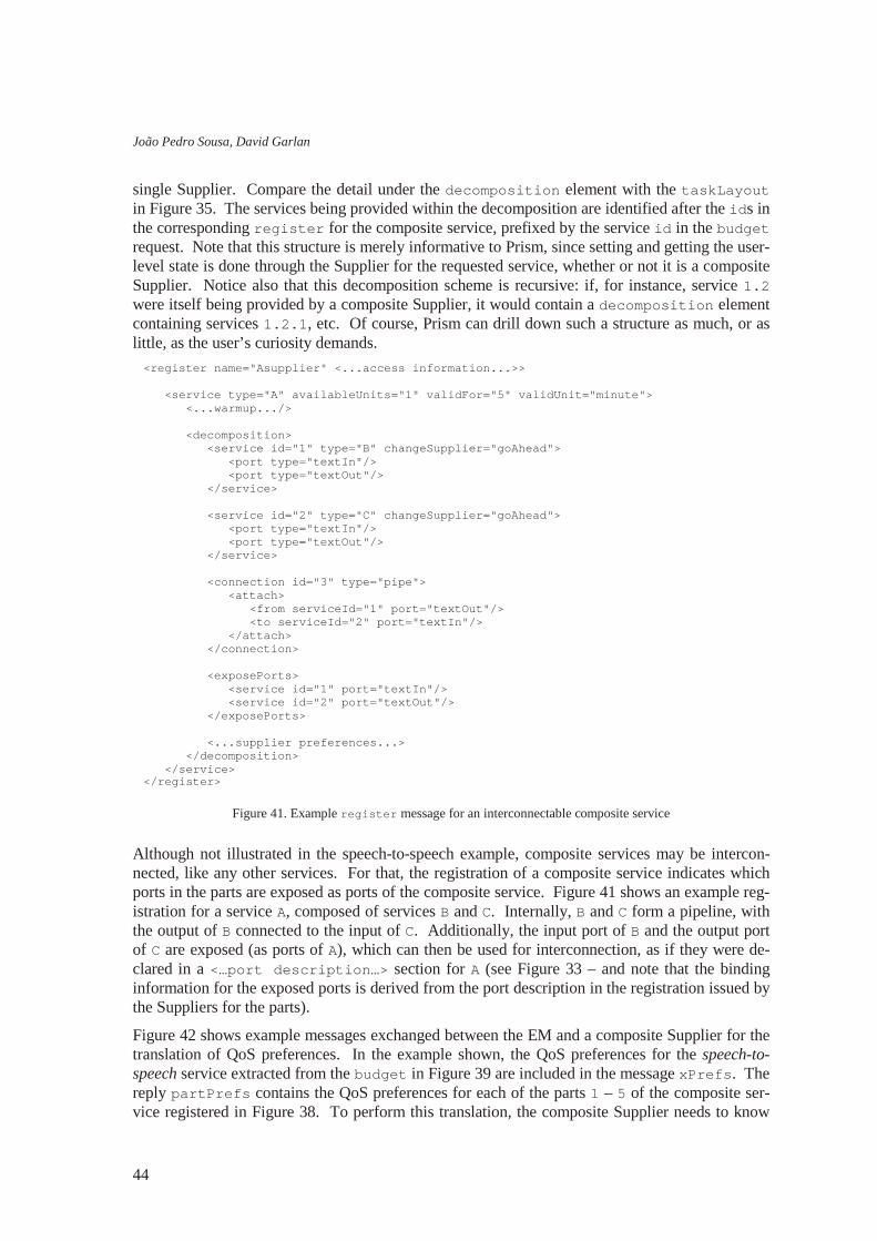
João Pedro Sousa, David Garlan
44
single Supplier. Compare the detail under the decomposi t i on element with the t askLayout in Figure 35. The services being provided within the decomposition are identified after the i ds in the corresponding r egi st er for the composite service, prefixed by the service i d in the budget request. Note that this structure is merely informative to Prism, since setting and getting the user-level state is done through the Supplier for the requested service, whether or not it is a composite Supplier. Notice also that this decomposition scheme is recursive: if, for instance, service 1. 2 were itself being provided by a composite Supplier, it would contain a decomposi t i on element containing services 1. 2. 1, etc. Of course, Prism can drill down such a structure as much, or as little, as the user’s curiosity demands.
Figure 41. Example r egi st er message for an interconnectable composite service
Although not illustrated in the speech-to-speech example, composite services may be intercon-nected, like any other services. For that, the registration of a composite service indicates which ports in the parts are exposed as ports of the composite service. Figure 41 shows an example reg-istration for a service A, composed of services B and C. Internally, B and C form a pipeline, with the output of B connected to the input of C. Additionally, the input port of B and the output port of C are exposed (as ports of A), which can then be used for interconnection, as if they were de-clared in a <…por t descr i pt i on…> section for A (see Figure 33 – and note that the binding information for the exposed ports is derived from the port description in the registration issued by the Suppliers for the parts).
Figure 42 shows example messages exchanged between the EM and a composite Supplier for the translation of QoS preferences. In the example shown, the QoS preferences for the speech-to-speech service extracted from the budget in Figure 39 are included in the message xPr ef s . The reply par t Pr ef s contains the QoS preferences for each of the parts 1 – 5 of the composite ser-vice registered in Figure 38. To perform this translation, the composite Supplier needs to know
<r egi st er name=" Asuppl i er " <. . . access i nf or mat i on. . . >> <ser vi ce t ype=" A" avai l abl eUni t s=" 1" val i dFor =" 5" val i dUni t =" mi nut e" > <. . . war mup. . . / > <decomposi t i on> <ser vi ce i d=" 1" t ype=" B" changeSuppl i er =" goAhead" > <por t t ype=" t ext I n" / > <por t t ype=" t ext Out " / > </ ser vi ce> <ser vi ce i d=" 2" t ype=" C" changeSuppl i er =" goAhead" > <por t t ype=" t ext I n" / > <por t t ype=" t ext Out " / > </ ser vi ce> <connect i on i d=" 3" t ype=" pi pe" > <at t ach> <f r om ser vi ceI d=" 1" por t =" t ext Out " / > <t o ser vi ceI d=" 2" por t =" t ext I n" / > </ at t ach> </ connect i on> <exposePor t s> <ser vi ce i d=" 1" por t =" t ext I n" / > <ser vi ce i d=" 2" por t =" t ext Out " / > </ exposePor t s> <. . . suppl i er pr ef er ences. . . > </ decomposi t i on> </ ser vi ce> </ r egi st er >

Aura Software Architecture
45
(a) the mapping between each dimension in the QoS preferences for the composite service and the QoS dimensions of the parts; and (b) the relationship between the QoS dimensions of the parts. Suppose, for instance, that the QoS preferences for speech-to-speech include two dimen-sions: the overall latency of the translation (of each utterance) and the accuracy of such transla-tion. Suppose further that the overall latency is the sum of the individual latencies, and that there is a known proportion between the latencies of each part. Given the good and bad limits of the total latency, the good and bad limits for the latency of each part are easily calculated. Similarly, suppose that the overall accuracy is given by a weighted sum (or by the product) of individual accuracies. Given a known relationship between individual accuracies, the preferences are easily translated. Notice how specific this kind of knowledge is to each composite service and to the assembly of the parts supporting it. Note also, that this translation is requested as needed. That is, if consecutive budget or set up requests refer to the same QoS preferences (for the composite service) there is no need to translate those every time.
Figure 42. Example messages for the translation of QoS preferences
Figure 43 shows example messages exchanged between the EM and a composite Supplier for combining QoS estimates. These messages are exchanged after the EM identifies the best match for the request in Figure 39, and computes the estimated QoS for all the Suppliers directly sup-porting the user’s task. In the example shown, the QoS estimates for the parts of the speech-to-speech service are included in the combi neQoS message. To perform the combination of esti-mates, the composite Supplier uses its knowledge about the mapping between the QoS dimen-sions of the parts and each dimension in the QoS preferences for the composite service. The overall QoS estimate is included in the whol eQoS reply. For reducing the message traffic during a sequence of budget or set up requests, the EM may cache the QoS estimates for all the Sup-pliers, and invalidate the estimate for the composite Supplier when any of the parts is adjusted – and only then request a new combination of the updated estimates.
<xPr ef s l ocat i on=" Acm-IPaddr" bi nd=" Acm-PortForEM" " > <ser vi ce t ype=" speechToSpeech" > <. . . speech- t o- speech QoS pr ef er ences. . . > </ ser vi ce> </ xPr ef s> <par t Pr ef s l ocat i on=" Acm-IPaddr" bi nd=" Acm-PortForEM" " > <ser vi ce t ype=" speechToSpeech" > <ser vi ce i d=" 1" > <. . . speech- r ecogni t i on QoS pr ef er ences. . . > </ ser vi ce> <ser vi ce i d=" 2" > <. . . l anguage- t r ansl at i on QoS pr ef er ences. . . > </ ser vi ce> <ser vi ce i d=" 3" > <. . . speech- synt hesi s QoS pr ef er ences. . . > </ ser vi ce> <connect i on i d=" 4" > <. . . connect i on QoS pr ef er ences. . . > </ connect i on> <connect i on i d=" 5" > <. . . connect i on QoS pr ef er ences. . . > </ connect i on> </ ser vi ce> </ par t Pr ef s>
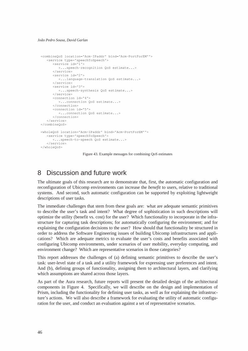
João Pedro Sousa, David Garlan
46
Figure 43. Example messages for combining QoS estimates
8 Discussion and future work The ultimate goals of this research are to demonstrate that, first, the automatic configuration and reconfiguration of Ubicomp environments can increase the benefit to users, relative to traditional systems. And second, such automatic configuration can be supported by exploiting lightweight descriptions of user tasks.
The immediate challenges that stem from these goals are: what are adequate semantic primitives to describe the user’s task and intent? What degree of sophistication in such descriptions will optimize the utility (benefit vs. cost) for the user? Which functionality to incorporate in the infra-structure for capturing task descriptions; for automatically configuring the environment; and for explaining the configuration decisions to the user? How should that functionality be structured in order to address the Software Engineering issues of building Ubicomp infrastructures and appli-cations? Which are adequate metrics to evaluate the user’s costs and benefits associated with configuring Ubicomp environments, under scenarios of user mobility, everyday computing, and environment change? Which are representative scenarios in those categories?
This report addresses the challenges of (a) defining semantic primitives to describe the user’s task: user-level state of a task and a utility framework for expressing user preferences and intent. And (b), defining groups of functionality, assigning them to architectural layers, and clarifying which assumptions are shared across those layers.
As part of the Aura research, future reports will present the detailed design of the architectural components in Figure 4. Specifically, we will describe on the design and implementation of Prism, including the functionality for defining user tasks, as well as for explaining the infrastruc-ture’s actions. We will also describe a framework for evaluating the utility of automatic configu-ration for the user, and conduct an evaluation against a set of representative scenarios.
<combi neQoS l ocat i on=" Acm-IPaddr" bi nd=" Acm-PortForEM" " > <ser vi ce t ype=" speechToSpeech" > <ser vi ce i d=" 1" > <. . . speech- r ecogni t i on QoS est i mat e. . . > </ ser vi ce> <ser vi ce i d=" 2" > <. . . l anguage- t r ansl at i on QoS est i mat e. . . > </ ser vi ce> <ser vi ce i d=" 3" > <. . . speech- synt hesi s QoS est i mat e. . . > </ ser vi ce> <connect i on i d=" 4" > <. . . connect i on QoS est i mat e. . . > </ connect i on> <connect i on i d=" 5" > <. . . connect i on QoS est i mat e. . . > </ connect i on> </ ser vi ce> </ combi neQoS> <whol eQoS l ocat i on=" Acm-IPaddr" bi nd=" Acm-PortForEM" " > <ser vi ce t ype=" speechToSpeech" > <. . . speech- t o- speech QoS est i mat e. . . > </ ser vi ce> </ whol eQoS>

Aura Software Architecture
47
9 References 1. G. Abowd, E. Mynatt. Charting Past, Present and Future Research in Ubiquitous Computing. ACM Transactions
on Computer-Human Interaction, 7(1), pp 29-58, March 2000. 2. R.K. Balan, J.P. Sousa, M. Satyanarayanan. Meeting the Software Engineering Challenges of Adaptive Mobile
Applications. Carnegie Mellon University Technical Report, CMU-CS-03-11, February 2003. 3. S.W. Cheng et al. Software Architecture-based Adaptation for Pervasive Systems. International Conference on
Architecture of Computing Systems: Trends in Network and Pervasive Computing. Karlsruhe, Germany. LNCS Vol. 2299, Schmeck, Ungerer, Wolf, (Eds.) April 2002.
4. E. Dashofy, D. Garlan, A. Koek, B. Schmerl. xArch: an XML Standard for Representing Software Architectures. http://www.isr.uci.edu/architecture/xarch/
5. D. Garlan, R. Monroe, D. Wile. Acme: Architectural Description of Component-Based Systems. Foundations of Component-Based Systems, Leavens and Sitaraman (Eds), Cambridge University Press, pp. 47-68, 2000.
6. D.Garlan, D.Siewiorek, A.Smailagic, P.Steenkiste. Project Aura: Toward Distraction-Free Pervasive Computing. IEEE Pervasive Computing, April-June 2002.
7. J. Magee, J. Kramer. Concurrency, State Models & Java Programs. John Wiley & Sons, 1999. 8. J.P. Sousa. Relieving Users from the Distractions of Ubiquity: a task-centered architectural framework. Thesis
proposal, Carnegie Mellon University, December 2, 2002. 9. J.P.Sousa. Online specifications of the Aura Software Architecture.
www.cs.cmu.edu/~jpsousa/research/auraSpecs 10. M. Weiser. The Computer for the Twenty-First Century. Scientific American, pp 94-100, September 1991.