the attitude control system of the wilkinson
TRANSCRIPT
THE ATTITUDE CONTROL SYSTEM OF THE
WILKINSON MICROWAVE ANISOTROPY PROBE
F. Landis Markley,* Stephen F. Andrews,? James R. O’Donnell, Jr.,** David K. Ward**
NASA Goddard Space Flight Center
ABSTRACT
The Wilkinson Microwave Anisotropy Probe mission produces a map of the cosmic microwave
background radiation over the entire celestial sphere by executing a fast spin and a slow
precession of its spin axis about the Sun line to obtain a highly interconnected set of
measurements. The spacecraft attitude is sensed and controlled using an inertial reference unit,
two star trackers, a digital sun sensor, twelve coarse sun sensors, three reaction wheel
assemblies, and a propulsion system. Sufficient attitude knowledge is provided to yield
instrument pointing to a standard deviation (lo) of 1.3 arc-minutes per axis. In addition, the
spacecraft acquires and holds the sunline at initial acquisition and in the event of a failure, and
slews to the proper orbit adjust orientations and to the proper off-sunline attitude to start the
compound spin. This paper presents an overview of the design of the attitude control system to
carry out this mission and presents some early flight experience.
INTRODUCTION
The Wilkinson Microwave Anisotropy Probe ( M A P ) . the second Medium-Class Explorer
(MIDEX) mission, was launched on June 30, 2001 as a follow-on to the Cosmic Background
Explorer (COBE), which made precise measurements of the cosmic microwave background
* Aerospace Engineer, Fellow AIAA, Greenbelt, MD, 20771, USA ? Aerospace Engineer, Greenbelt, MD, 20771, USA ** Aerospace Engineer, Senior Member AIAA, Greenbelt, MD, 20771, USA
1
https://ntrs.nasa.gov/search.jsp?R=20040034039 2018-02-14T00:28:17+00:00Z

(CMB) that is believed to be a remnant of the Big Bang marking the birth of the universe.I4
WMAP has measured the CMB anisotropy with sensitivity 50 times that of the Differential
Microwave Radiometer (DMR) instrument on COBE and angular resolution 30 times finer,
specifically 20 microKelvin and 14 arc minutes, respectively, enabling scientists to determine the
values of key cosmological parameters and to answer questions about the origin of structure in
the early universe and the fate of the uni~erse.~’
Since the major error sources in the DMR data arose from COBE’s low Earth orbit, WMAP was
placed in a Lissajous orbit around the Sun-Earth L, Lagrange point to minimize magnetic,
thermal, and radiation disturbances from the Earth and Sun. WMAP attained its Lissajous orbit
around L, in early October 2001, about 100 days after launch by a Delta 11 launch vehicle, using
a lunar gravity assist following three phasing loops, as shown in Figure 1. The trajectory design
and opeiatioiis x e discussed in detzil in Refs. 7-12
Figure 1: W W Trajectory to L2
2

The WMAP instrument includes radiometers at five frequencies, passively cooled to about 90"K,
covering two fields of view (FOVs) 141 " apart on the celestial sphere. The WMAP observatory
executes a fast spin coupled with a slower precession of its spin axis at a constant angle of 22.5"
from the Sun line to obtain a highly interconnected set of measurements over an annulus between
87" and 132" from the Sun. The rotation about the spin axis has to be at least an order of
magnitude faster than the rate of precession of the spin axis; the rates chosen were 2.784 deg/s
(0.464 rpm) for the spin rate and -0.1 de& (1 revolution per hour) for the precession rate. Figure
2 shows the scan pattern covered by one of the two FOVs in one complete spacecraft precession
(1 hour), displayed in ecliptic coordinates in which the ecliptic equator runs horizontally across
the map. The bold circle shows the path for a single spin (2.2 minutes). As the Earth revolves
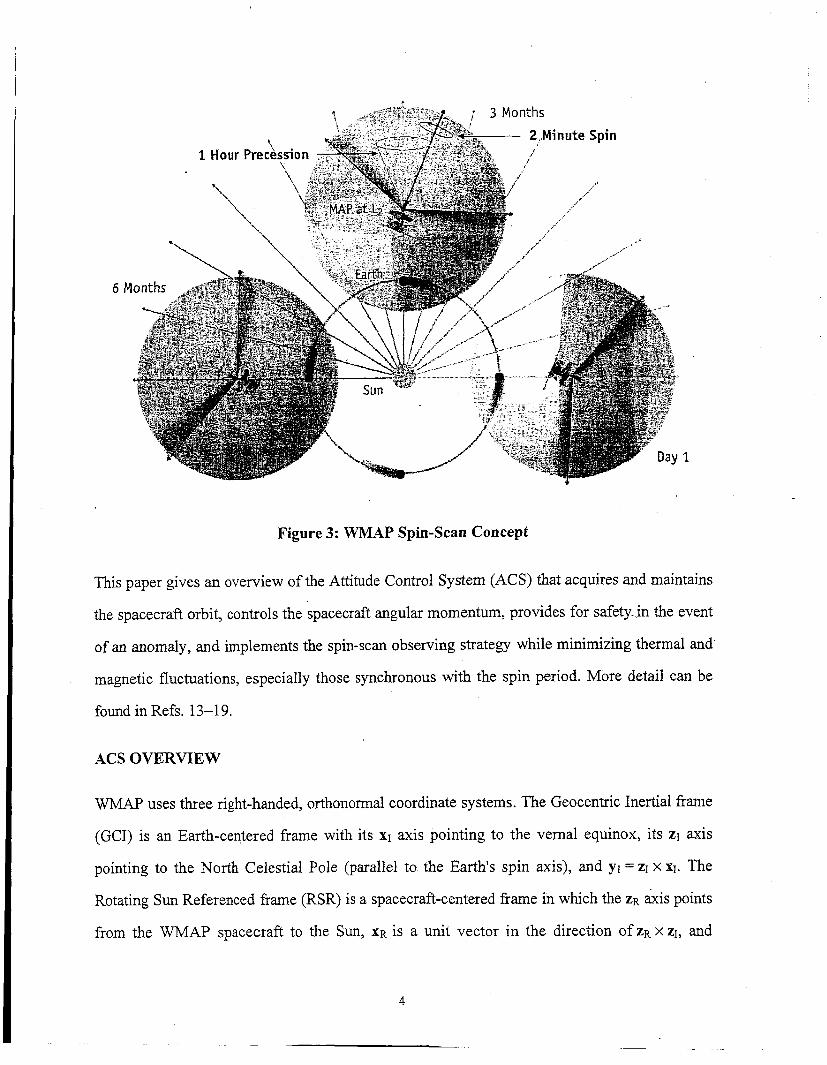
around the Sun, this annulus of coverage revolves about the ecliptic pole as shown in Figure 3.
Thus the entire celestial sphere will be observed once every six months, or eight times in the
planned mission life of f c i yeas.
North Ecliptic Pok
93"
South Ecliptic Fob
93"
Figure 2: WMAP Scan Pattern
3
6E
Figure 3: WMAP Spin-Scan Concept
This paper gives an overview of the Attitude Control System (ACS) that acquires and maintains
the spacecraft orbit, controls the spacecraft angular momentum, provides for safety in the event
of an anomaly, and implements the spin-scan observing strategy while minimizing thermal and
magnetic fluctuations, especially those synchronous with the spin period. More detail can be
found in Refs. 13-19.
ACS OVERVIEW
WAF' uses three right-handed, orthonormal coordinate systems. The Geocentric Inertial kame
(GCI) is an Earth-centered frame with its XI axis pointing to the vernal equinox, its ZI axis
pointing to the North Celestial Pole (parallel to the Earth's spin axis), and y~ = ZI x XI. The
Rotating Sun Referenced frame (RSR) is a spacecraft-centered frame in which the ZR axis points
from the WMAP spacecraft to the Sun, XR is a unit vector in the direction of ZR x 21, and
4

yR = ZR x xR. The RSR frame rotates at approximately 1 "/day with respect to the GCI frame. The
body frame is centered at the spacecraft center of mass with ZB axis parallel to the spacecraft
centerline, directed from the instrument to the solar arrays, YB axis normal to the instrument
radiator faces, and XB = YB x ZB, as shown in Figure 4. As a minimum, all the WMAP ACS
control modes maintain the spacecraft ZB axis within 25" of the Sun, to satisfy thermal and power
constraints.
Instrument priraary mirrors \ 1
% axis 1 Sun shield'
Figure 4: Spacecraft Layout
The WMAP attitude is sensed by an Inertial Reference Unit (IRU), two Autonomous Star
Trackers (ASTs), a Digital Sun Sensor (DSS), and twelve Coarse Sun Sensors (CSSs); it is I i
controlled by three Reaction Wheel Assemblies (RWAs) and a propulsion system. Figure 5 ~
illustrates the WMAP ACS architecture. More detail on the WMAP ACS hardware suite can be
found in Refs. 16 and 19.
5

, Sync.
ACS PmeSsor
C&DH
4
! 1773 Fiber-
!
---- I I
optic Bus T ACE
Attitude Conml Elecmnics Sak hold Pnxessor
I .
Figure 5: Attitude Control System Architecture
The IRU comprises two Kearfott Two-Axis Rate Assemblies (TARAs), one with input axes
aligned with the ZB and XB axes and the other with input axes aligned with the ZB and YB axes.
This gives redundant rate inputs on the ZB axis; the DSS outputs can be differentiated to provide
rates on the other axes in the event of an IRU failure.
The boresights of the two Lockheed-Martin ASTs'* are in the ~ Y B directions. Each AST tracks
up to 50 stars simultaneously in its 8.8" square FOV, matches them to stars in an internal star
catalog, and computes its attitude as a GCI-referenced quaternion with accuracy of 21 arc-
seconds (la) around its boresight axis and 2.3 arc-seconds (lo) in the other two axes.
6
The Adcole two-axis DSS has two heads, each with 64" square FOV and an accuracy of 1 arc-
minute (30). The centers of the FOVs of the two heads are in the XB-ZB plane at angles of f29.5"
from the zB-axis. The CSSs are cosine eyes located in pairs looking outward from the edges of
the six solar array panels, alternately pointing 36.9" up and 36.9" down from the XB-YB plane.
The RWAs are Ithaco Type E wheels each with a momentum storage capacity of 70 Nms. The
available reaction torque of each wheel is 0.35 Nm, but this is limited to 0.215 Nm by the
WMAP software to satisfy power constraints. The reaction wheel rotation axes are tilted 60"
from the -ZB axis and uniformly distributed 120" apart in azimuth about this axis. The wheels
serve the dual function of counterbalancing the body's spin angular momentum to maintain the
system momentum (i.e. body plus wheels) near zero while simultaneously applying control
torques to provide the desired spacecraft attitude. The wheel axis orientations result in all wheel
speeds being biased away from zero while the spin-scan observing motion is being executed,
thus avoiding zero-speed crossings that would occur if the wheel spin axes were oriented along
the spacecraft body frame coordinate axes.
The propulsion system comprises eight monopropellant hydrazine Reaction Engine Modules
(REMs) and associated hardware. Each REM generates a maximum thrust of 4.45 N.
MOMENTUM MANAGEMENT STRATEGY
The choice of an L2 orbit to minimize magnetic, thermal, and radiation disturbances precludes
the use of magnetic sensing or torquing. Thus, the propulsion system provided for orbit
maneuvers and stationkeeping is also used to unload accumulated system angular momentum
after each orbit adjust. These occur several times in the phasing loops but no more than once
every three months at Lz to minimize interruptions of science observations. The RWAs can store
on the order of 70 Nms of angular momentum in non-spinning modes, and a significant fraction
of this along the ZB axis while spinning about this axis. While executing the Observing Mode
7

spin-scan, however, the transverse momentum storage capacity (i.e. in the XB-YB plane) is limited
to 3 Nms, the amount that can be cycled among the three RWAs at the fast spin rate without
adversely affecting attitude control.
Gravity-gradient, atmospheric drag, and outgassing torques are significant in the phasing loops,
but the accumulated angular momentum of less than 1 Nms per orbit is easily stored until
removal following orbit maneuvers at apogee or perigee. Solar radiation pressure torque is the
only significant disturbance torque at L2, and the uniform rotation of the spin axis reduces its
average along the XB and Y B axes by more than two orders of magnitude compared to its
instantaneous value. The only potentially troublesome component is a “pinwheel” torque along
the ZB axis, which might result from an imperfect deployment of the solar array panels. The
angular momentum is accumulated in inertial space, so it is clear from Figure 3 that the pinwheel
torque at one point in the orbit leads to a transverse angular momentum one-quarter orbit, or 91
days, later. This means that any accumulation of angular momentum from the pinwheel torque of
more than about 0.03 Nms per day would require momentum unloading more frequently than
desired.
Pre-flight estimates of the pinwheel torque gave angular momentum accumulation ranging from
0.0016 to 0.065 Nms per day, depending on the accuracy of deployment of the solar arrays and
the resulting symmetry of the ~pacecraft.’~ The worst-case estimate would reach the Observing
Mode system angular momentum limit of 3 Nms in 46 days, which is highly undesirable. Flight
data indicates an angular momentum accumulation of about 0.005 Nms per day, which easily
meets the three-month requirement. In fact, since this is less than 0.03 Nms per day, Figure 3
shows that the pinwheel torque will begin to unload the accumulated angular momentum on the
next quarter orbit, so no unloading by the REMs is required at all, in principle. The orbit
perturbations at L2 have also been well within requirements, so it has been possible to perform
stationkeeping and momentum unloading only once every four months, rather than every three
months.
8

ACS OPERATIONAL MODES
WMAP has six ACS modes. The Inertial,
Observing, Delta V, Delta H, and Sun
Acquisition modes are implemented in the main
spacecraft (Mongoose V) processor, while the
Safehold Mode resides in the Attitude Control
Electronics Remote Services Node (ACE RSN).
Figure 6 shows the modes and the transitions
ACE Every mode
among them. Anomalous behavior can result in
autonomous transitions from any other mode to
Sun Acquisition Mode or Safehold Mode, even
though these transitions are not shown explicitly.
Each of the modes of the WMAP ACS will be Figure 6: ACS Mode Transitions
discussed below, including a discussion of the
sensors, actuators, and control algorithms used in
that mode. Examples of in-flight performance are
also provided.
ACS DESIGN AND PERFORMANCE
Sun Acquisition Mode
Sun Acquisition Mode uses the CSS, IRU, and RWAs to acquire and maintain the spacecraft ZB
axis within 25" of the Sun, starting from any initial orientation and with any initial body
momentum less than [13, 13, 551 Nms. 'l'his is a thermally safe and power-positive orientation
before instrument power-on, and this is the mode entered after separation from the launch
9
vehicle. If the rates at entry to the RWA-based Sun Acquisition Mode exceed those that can be
handled by this mode, the REM-based DeIta H Mode is entered to reduce t h e rates to an
acceptable level, after which the spacecraft returns to Sun Acquisition Mode. Transition from
Sun Acquisition Mode to Inertial Mode can be commanded after the Sun has been acquired.
Transition to the Mongoose control modes from the ACE Safehold Mode is through Sun
Acquisition Mode. Normal exit from Sun Acquisition Mode is to either Delta H or Inertial Mode,
depending on the residual spacecraft spin rate.
The attitude error signals in Sun Acquisition Mode are calculated by computing the cross product
of theaun vector computed from CSS measurements with the desired sun vector. The nominal
desired sun vector points the +ZB axis, the solar array normal, directly at the sun. The attitude
error signals are limited and multiplied by the proportional control gain. The rate error signal is
the body rate measured by the IRUs. The rate error vector is multiplied by the spacecraft inertia
and then each axis is multiplied by a derivative control gain. The output of this proportional-
derivative (PD) control algorithm is three torque commands in the body frame. A body-to-wheel
reference frame transformation matrix is used to transform these commands to the reaction wheel
frame. The wheel torque commands are scaled down by a common factor if the largest command
exceeds the wheel torque capability, so that the torque direction is preserved while the largest
command is the maximum reaction wheel torque command.
In pre-launch analysis and testing, Sun Acquisition Mode was found to meet its performance
requirements for all initial system mommtum magnitudes of 55 Nms or less. Because this level
represented 20 separation rates from the Delta IT third stage, a contingency thruster momentum
unload was unlikely, but would be possibly needed. In addition, there were a few degenerate
cases (e.g., 180 degrees off of the sun with zero rates) that did not satisfy the requirements, but
these were deemed too unrealistic to be of concern.
10

Performance on orbit was as expected from the pre-launch testing. After a post-launch
communications gap, contact was established with WMAP via the Tracking and Data Relay
Satellite TDRS-W at 21:03, 77 minutes after launch and 10 minutes prior to spacecraft
separation. At the beginning of this contact, WMAP was still in the Delta I1 third-stage spin;
b cyro rates were saturated (over 5.3"lsec) and the system momentum magnitude measurement was
over 90 Nms, as shown in Fig. 7. At 21:13, the yo-yo despin from the third-stage spin occurred,
and WMAP separated from its booster. Within one telemetry update (16 seconds), the gyros
desaturated with all axes below 1 Ohecond. The measured system momentum dropped in that
update to approximately 10 Nms. The solar arrays began to deploy 14 seconds after separation.
The spacecraft reported that the arrays were deployed (all arrays deployed to within 25" of their
fully deployed state) 8 seconds later. The inset in Figure 7 shows the change in the system
momentum magnitude measurement as the mass properties of the spacecraft changed during
aiq deployment aad $de! spin down. The m 2 y s opened fully in four minutes, at which point the
system momentum magnitude was 7 Nms-well within the maximum level of 55 Nms at which
Sun Acquisition Mode could acquire the sun.
Figure 8 shows the CSS and DSS measured sun angles at separation. Note that the sun was out of
the DSS field of view until 5530 seconds of the plot. The spacecraft acquired the sun within 7
minutes of separation. The spacecraft was declared separated and safe on the sun at 2126, 13
minutes after separation.

AGs(pO42) 1 ,o;:80
NoY Z&unch-dayglayback Measured System Momentum Magnitude [a=-sysmommd I " I ~ ' " l ' ' '
- I 1 " I
Time hom Launch (seconds)
Figure 7: System Momentum Magnitude at Separation
I
----I _ _ _ _ _ _ _ _ - - - y - - - , , . I L i 0 ' . ' 6000 65W 7000 5500
Time hwn Launch (semW
Figure 8: Sun Angles at Separation
12

In the design of the Failure Detection and Correction logic for WMAP, Sun Acquisition Mode
was used in many cases as a first level of safing in the event of a problem. Fortunately, there
were no on-orbit anomalies that caused an autonomous entrance into Sun Acquisition Mode.
During the first week of the launch and in-orbit checkout period, Sun Acquisition Mode was
used as the “base” mode to keep the spacecraft in when other operations were not being
conducted. Once Observing Mode was checked out, it or Inertial Mode became the base mode.
The maneuver plan used for each of the calibration maneuvers at apogee and orbit maneuvers at
perigee commanded the spacecraft into Sun Acquisition immediately after the bum. In all cases,
the mode satisfied all of its requirements.
Inertial Mode
Inertial Mode acts as a staging mode between the other operations of the spacecraft; all
Mongoose modes other than Delta ‘J have the cqa5i:i;y to enter this node. Inertial IMode can
either hold the spacecraft in an inertially-fixed orientation or slew the spacecraft between two
lfferent orientations. This is an RWA- and IRU-based mode, with DSS and AST measurements
used in an onboard Extended Kalman Filter to update the gyro bias and quaternion error
estimates. Normal exits from Inertial Mode are by ground command only. The high-level
requirements for Inertial Mode are to acquire and hold a fixed target quaternion within
10 minutes and to maintain the spacecraft ZB axis within 25” of the sunline at all times. The
desired orientation is commanded as a desired GCI-to-body quaternion qc.20*21 A slew will be
executed if this is not close to the current spacecraft orientation. The attitude control is by RWA
torques, which are computed by a PD controller in terms of attitude and rate errors.
The attitude errors are expressed as twice the vector part q, of an error quaternion, which is the
quotient of the commanded quaternion and an estimated quaternion 4 :
q, = kqc Q 4 - I
13

In this and the following we use the quaternion product convention of Refs. 21 and 22 rather than
that of Ref. 20 so that the order of quaternion multiplication is the same as that of the
corresponding direction cosine matrices. The sign in the equation above is chosen to assign a
positive sign to the scalar component of q,, which has magnitude close to unity for small
pointing errors. The small angle approximation is used at all times for the attitude error; this
introduces inaccuracies for large slews, but does not affect the performance of the controller, and
as there is not direction preference for the slews, it is not a problem.
A dynamic attitude limiter is employed in Inertial Mode to enable the spacecraft to meet the 25"
sun constraint during slews. Before implementing the limiter, the sun line angle reached as high
as 38" in simulated 45" Inertial Mode slews including high spin errors in the ZB axis,. The
dynamic attitude error limiter calculates an attitude error limit for each axis proportional to the
error in that axis. This preserves the direction of the resulting slew and prevents the spacecraft
fiom violating the sun constraint for any slews with spin angles from 0" to 180".
The estimated quaternion is computed by the Kalman filter, with IRU, AST, and DSS
measurements as This is similar to Kalman filters employed on several previous
Goddard Space Flight Center missions, except that the AST produces a measured attitude
quaternion rather than observed star vectors. This simplifies the onboard software computations
by removing the burden of star identification and the necessity to carry an onboard star catalog.'*
The Kalman filter will be discussed in more detail later in this paper.
The onboard Kalman filter also estimates corrections to the gyro drift rates that are subtracted
from the IRU-measured body rates to produce the body rate vector. Since the desired rates in
Inertial Mode are zero, the rate error vector o, is the negative of the body rate vector measured
by the IRU:
~
0, =-aB*
14
.2426 The commanded control torque in the body coordinate system is given by.
where J is the WMAP moment of inertia tensor, and k,, kp, and ki are the derivative, proportional,
and integral gains, respectively (ki is nominally zero). The factors of two multiplying the error
quaternion and its integral reflect the fact that the quaternion errors are half the angle errors in
the small angle approximation. The controller outputs are the same type of torque commands as
described in the Sun Acquisition section, and are sent to the RWAs in the same manner.
In addition to accepting ground-commanded attitudes, Inertial Mode has two "precanned"
quaternions onboard. One will point the spacecraft +ZB axis towards the sun, and the other will
point the spacecraft +ZB axis 22.5" from the sun. The commands have fixed quaternions relative
to the RSR frame described previously. The RSR frame orientation relative to the GCI frame is
calculated as a quaternion every minute onboard, and this quaternion is multiplied by the stored
quaternion at the command time to yield the commanded body attitude relative to the GCI frame.
Inertial Mode also accepts quaternions fiom a Command Quaternion Table (CQT), which is a
table of times and quaternions representing a particular attitude profile for the duration of the
CQT. The CQT can be loaded with different quaternion sequences, and was used to command
the gyro calibration slew profile as part of the in-orbit checkout. The CQT was also used to
command the spacecraft to the proper burn orientations, and to command the spacecraft to hold
the thrust direction parallel to the velocity vector before, during, and after the maneuvers.
WMAP was in Inertial Mode for a long period of time during the first week of the mission,
leading to one surprise: Inertial Mode does not hold the spacecraft in an inertially fixed
orientation. When the spacecraft was commanded to point at the current sun location (via the sun
pointing precanned command discussed above), the sunline angle fiom the spacecraft ZB axis was
expected to change by about one degree per day, consistent with the spacecraft's motion relative
15
to the sun. Instead, the spacecraft telemetry showed that the spacecraft maintained a sun-pointing
attitude. The difference between the estimated quaternion and the command quaternion slowly
climbed at approximately 1 deg/day, and was "reset" to zero whenever we commanded a sun-
pointing attitude, as expected. However, the telemetered attitude errors and sun angles did not
reflect this. Inspection of the flight code and ACS simulation code revealed that the portion of
the simulation used to automatically generate flight software only understands commands and
attitudes in the RSR frame. When a new inertial (GCI) quaternion is commanded, the flight
software converts it to an RSR reference frame quaternion before handing it off to the controller.
If this conversion were done each time the controller was entered @e., once per second) or when
the ephemeris was updated, then the command quaternion within the Inertial Mode controller
would remain inertially fixed. However, this conversion is only done with the initial command,
so the controller continues to control to the static RSR frame quaternion. As the ephemeris
updates wld the RSR frame Ewes , the cmtro!ler moves with the RSR frame. Thus, commanding
a sun-pointing attitude results in the Inertial Mode controller continuing to follow the sun. This
was not discovered in testing primarily because nominal operations never involved remaining in
Inertial Mode for an entire day. The longest stay in Inertial Mode in a simulation run, build test,
or acceptance test was an hour or less, so the effect was too small to be seen in the test data.
Observing Mode
Observing Mode is an IRU-based mode used for science operations, using the same Kalman
filter as Inertial Mode. The RWAs provide the angular momentum that preserves a near-zero
system momentum and the torques that maintain both the 22.5" angle between the spin axis and
the sunline and the desired sky-scan rates illustrated in Figure 2. The tolerance on both rates is
5%, and the tolerance on the Sun line angle is 0.25". Observing Mode differs from Inertial Mode
in that the commanded quaternion is time-varying, the commanded rates are non-zero, and a
commanded acceleration and a commanded gyroscopic torque are used in a feedforward loop to
eliminate attitude hangoff. The attitude error is computed as in Inertial Mode, but the
16

commanded attitude quaternion comes from the desired motion relative to the sunline, rather
than being fixed. Nornial transitions into or out of Observing Mode are via Inertial Mode.
The commanded inertial quaternion is computed as the product of an RSR-to-body and a GCI-to-
RSR quaternion:
The GCI-to-RSR quaternion is computed onboard from ephemeris models. The desired RSR-to-
body attitude is more conveniently expressed in terms of 3-1-3 Euler anglesm321 than in terms of a
quaternion. The commanded values of the three Euler rates are those that give the desired scan
rates:
GC = -1 rev/hour =-0.001745 rad/sec
@, = 0.464 rpm = 0.04859 rad / sec e, = o
The commanded values of the three Euler angles are then given by: .
t
(ft = Go + j &dt
w c = w o + j IG/cdt
t0
0, = 22.5' = 0.3927 rad t
'0
where Q0 and wo are set by the initial state and 0, by the desired Sun angle. These 3-1-3 Euler
angles are converted to the commanded RSR-to-body quaternion q B R by the standard
equations .m,21
The rate error vector a, is the difference between a commanded body rate vector oc and the
body rate vector a,, measured by the IRU:
17

The commanded body rate vector o, is computed from the commanded Euler angles and rates
by the standard
change when entering or exiting the mode would not cause the spacecraft to violate the sunline
constraint. If the rate error is too large, than the rate path saturates the wheel command, and no
attitude error signal gets into the control torque. The result is an uncontrolled spacecraft attitude
until the rate errors are small. The initial commanded rate is differenced with the previous
derived rate, limited, and then integrated to get a new derived rate, as shown in Figure 9. This
I
This commanded rate is modified in the Observing Mode controller so that a large rate command
new commanded rate is used to calculate the rate error described above and the feedforward
terms discussed below. The result is a steady increase in the amount of the initial command rate
fed into the control system, which generates a spin up (when entering) and a spindown (when
exiting) Observing Mode. This effect is seen in Figure 10. This shows the initial slew (starting
just after 1000 seconds on the plot) from the z, axis on the sunline to the 22.5" sunline angle, and
then the spinup into the compound spin, starting at about 1600 seconds on the plot.
Figure 9: Commanded Rate Limiting
18
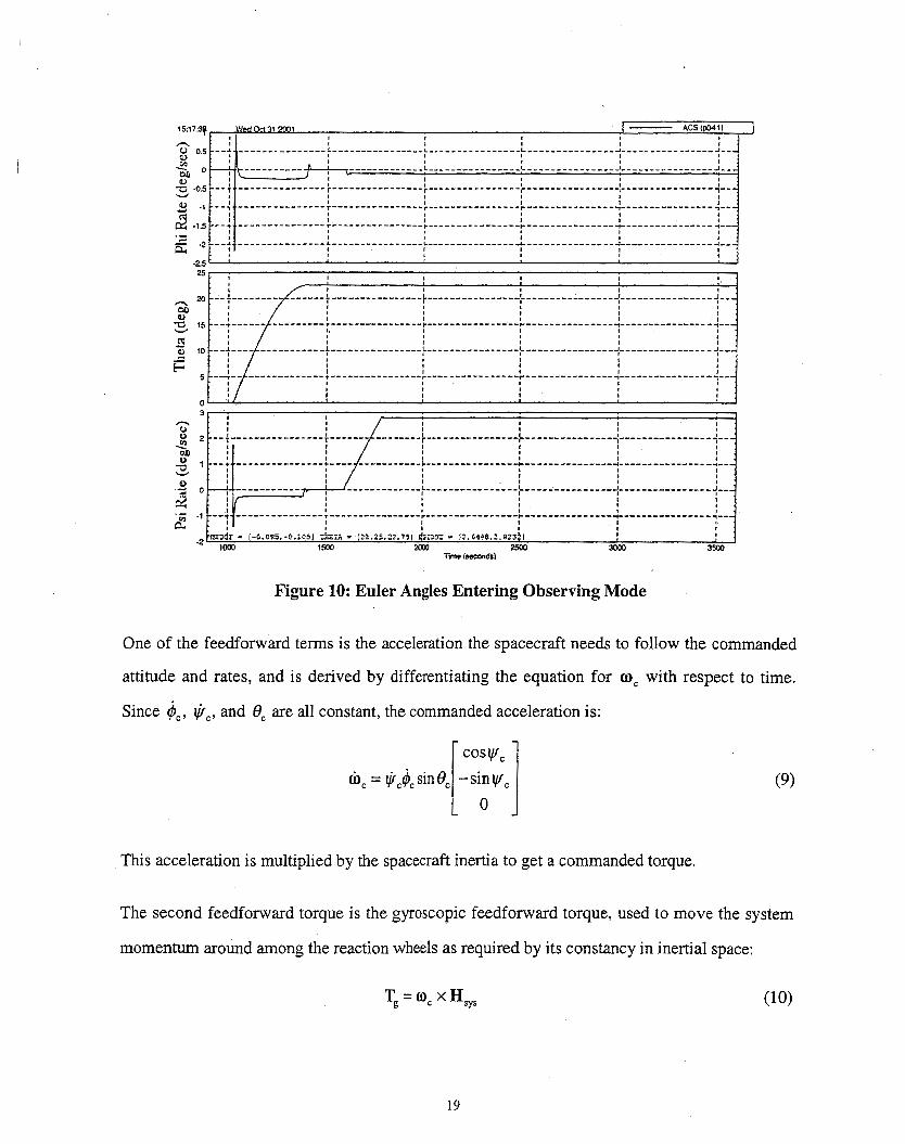
Figure 10: Euler Angles Entering Observing Mode
One of the feedforward terms is the acceleration the spacecraft needs to follow the commanded
attitude and rates, and is derived by differentiating the equation for O, with respect to time.
Since $,, I,+~, and 0, are all constant, the commanded acceleration is:
(9)
This acceleration is multiplied by the spacecraft inertia to get a commanded torque.
The second feedforward torque is the gyroscopic feedforward torque, used to move the system
momentum around among the reaction wheels as required by its constancy in inertial space:
Tg = "c H s y s
19

These feedforward torques are added to the output of the PD controller to generate the complete
control torque for the RWAs:
This control torque is in the body frame, and is treated the same as the control torque created in
Inertial Mode and Sun Acquisition Mode.
Initially, the precession rate Q) in Observing Mode did not meet its 5% accuracy requirement,
showing a 7% variation at the spin period. This was attributed to an inaccurate value of system
momentum in the gyroscopic feedforward loop arising from a scale factor error in the RWA
tachometer signals. Evidence for this was that the magnitude of the system momentum, which
should be constant, had a 0.4 Nms oscillation at spin period and increased during spin-up by 1.0
Nms. Comparing a high-fidelity simulation with flight data determined that the oscillation and
spin-up offset could be removed by a small change in the tachometer scale factors by about 2.5%
for RWA1 and about 4% for RWA2 and RWA3. After loading these new scale factors, the
variation of the precession rate was dramatically reduced, as were the spin-period oscillation and
the spin-up offset in the computed system momentum magnitude shown in Figure 11. A recent
analysis is in basic agreement with this analysis."
Once all sensors and actuators were calibrated, Observing Mode met the 5% requirement on the
commanded Euler rates and the 0.25" sun angle control requirement, as shown in the time plots
in Figure 12 and the nearly perfect circle described by the sun sensor data in the body frame
displayed in Figure 13.
20

Figure 11: Pre- and Post-Calibration System Angular Momentum Magnitude
Figure 12: Post-Calibration Observing Mode Performance
21

spacecraft x component of sun unit vector
Figure 13: DSS Measurements in Observing Mode
Delta V Mode
Delta V Mode, which uses the REMs to adjust the orbit in either the initial phasing loops or for
Lz stationkeeping, is only entered from Inertial Mode by a command sequence specifying burn
duration, direction and start time. The desired attitude in terms of either a single quaternion or a
CQT can be configured either via command or by table load. The desired set of thrusters to be
used is specified via command. The spacecraft remains in Inertial Mode to slew from the initial
orientation to the desired attitude for the start of the maneuver, and transitions to Delta V Mode
at the start time of the requested burn. The only sensors used in Delta V Mode are the IRU and
RWA tachometers. This mode uses a PD controller to hold the spacecraft to a commanded
22

quaternion attitude while executing the Delta V burn. The output of the controller is transformed
into thruster firing commands using a pulse width modulator with a minimum pulse width of
0.04 sec. The desired attitude is held by off-pulsing the primary set of thrusters and on-pulsing
the others. Normal exit is autonomously to Delta H Mode.
Anomalous spacecraft motion experienced during some early maneuvers was later attributed to
torques caused by the evaporation of ice condensed on the back of the solar arrays and sun
shields.28 Despite this unexpected phenomenon, maximum pointing errors during the nine Delta
V maneuvers performed in the first three months of the mission were smaller than predicted (3.7"
vs. 5.5"), and the imparted velocity increments were accurate to 1%. Less than 15 kg of
hydrazine propulsion fuel was expended to get to L2, about half the amount budgeted for this
phase of the mission. The 57 kg of fuel remaining for stationkeeping and momentum unloading
at L2 will easily support a four-year extended mission.
Delta H Mode
Delta H Mode uses the REMs to unload spacecraft system angular momentum, which is
computed using the RWA tachometers and IRU. It is used primarily upon exit from Delta V
Mode, but can be commanded from Inertial or Sun Acquisition Mode if necessary, although this
is not anticipated. The same pulse width modulator is used for Delta H as for Delta V, with the
exception that all thrusters are operated in an on-pulsing manner for Delta H. If entry was from
Delta V or Inertial Mode, the ACS autonomously transitions to Inertial Mode after the
momentum has been reduced to less than 0.3 Nms. If Delta H Mode was entered from Sun
Acquisition Mode, as discussed above, the autonomous exit upon completion of the momentum
unloading is back to Sun Acquisition Mode.
23

Safehold Mode
Safehold Mode is implemented in the ACE, so it can be entered autonomously in the event of a
Mongoose anomaly. It has two configurations, which differ by the rate information used. The
first, SafeholdfIRU, is a copy of the Sun Acquisition Mode in the Mongoose. The second,
Safehold/CSS, is a minimum-hardware mode using only the RWAs and CSSs, with rate errors
being computed by numerically differentiating the position error signals. Because it lacks body z
rate information from the gyros, SafeholdCSS can tolerate less system momentum than can Sun
Acquisition or SafeholdJIRU Mode. Since the CSSs are insensitive to rotations about the Sun
line, anti-runaway compensation is applied to prevent the wheels from uncontrolled spinning
about the satellite’s zB-axis. This is accomplished by applying equal damping torques to the three
wheels if the sum of their speeds exceeds a pre-set value, thereby suppressing zB-axis rotation
without applying a net torque in the XB-YB plane. Exit from either Safehold Mode is by ground
command only.
Charged particle flux from extreme solar activity on November 5,2001 caused a power-on reset
of the Mongoose processor. The ACS transitioned autonomously to Safehold Mode in the ACE,
which functioned exactly as designed to keep WMAP safe. The transition to Safehold Mode was
discovered by operations staff at the next telemetry pass about 12 hours later, and recovery to
Observing Mode was accomplished within three hours of this discovery.
ATTITUDE DETERMINATION KALMAN FILTER
Implementation and Operation
The WMAP Kalman filter is an Extended Kalman Filter that uses AST and DSS measurements
to update the IRU-propagated attitude and to update the estimated IRU drift rate. The Kalman
filter operates in Sun Acquisition or Safehold Modes, but the spacecraft does not use its output
for attitude knowledge in those modes, which control the spacecraft based on an attitude
24

calculated from the CSS measurements. Sun Acquisition Mode is thus ideal for observing the
Kalman filter performance before using its output to control the spacecraft. The first time the
Kalman filter was enabled in Sun Acquisition Mode, parameters such as the measurement noise
Noise Darameter
covariance matrix, the initial covariance matrix, and the residual tolerances were increased to
launch values, since the sensors had not been calibrated in flight yet (Table 1). The larger initial
parameter values allowed the filter to converge and estimate attitude corrections and IRU bias,
albeit at less accuracy than possible with a fully calibrated system.
Launch Value Nominal Value
During each control cycle, the IRU, DSS, and AST data are sampled at slightly different (but
deterministic) times. The previous control cycle’s estimated attitude quaternion is propagated to
the current sample cycle time with a first-order propagator” using the IRU-measured rates,
corrected with the previous cycle’s gyro bias estimate. The attitude control is executed based on
that propagated attitude and measured rate. The DSS and AST data are processed in the sensor
data processing algorithms, and the resulting measurements (sun vector and attitude quaternion)
are back-propagated to the IRU sample time with another first-order propagator, using the
current body rate measurement. The back propagation removes any attitude error that may result
from the timing differences between the sensor samples, especially at the nominal Observing
25

Mode spin rate. The Kalman filter uses the synchronized measurements to update the propagated
quaternion, the estimated gyro drift bias, and the propagated covariance matrix.
Submodes within each control mode are used to determine whether or not the filter will update
the attitude and gyro bias estimate. In general, if the control mode produces accelerations on the
body, the Kalman filter is set to propagate the covariance matrix, and the estimated attitude and
gyro bias are not updated. In Inertial Hold State and Observing Scan/Hold State, the Kalman
filter is used to update the estimates.
Attitude Estimate
The measurement residuals, the difference between the measured quantity and the expected
(modeled) quantity, are a good indication of how well the Kalman filter is estimating the
spacecraft attitude. Figures 14 and 15 show a typical one-hour period in Observing Mode at L,
for the DSS and the AST, respectively. Much of the DSS residual is dominated by noise from the
measurement, but all axes show some spin-period frequency oscillations. The short-period
oscillations are due to inaccuracies in the first-order attitude propagator used onboard (discussed
below), and the longer period oscillations at the precession period are due to small remaining
misalignments between the AST and the DSS.
Figure 15 shows the most striking pattern in the AST xB-axis residuals. Good measurement
accuracy is indicated by the small amount of noise present (a few arcseconds, as in the ZB axis),
but periodic oscillations with magnitude ~ 3 0 arcseconds are quite apparent. There is also a large
15-arcsecond jump near each peak. These oscillations and jumps are about 90" out of phase with
the yB-axis pattern. In fact, the large jumps coincide with the zero crossing of the spacecraft body
rate in each axis. Since the body rates are smooth and continuous, the error is probably in the
attitude propagated from that rate signal. The first-order numerical integrator used to propagate
the quaternion may induce errors on the order of 15 arcseconds when the rate signal crosses zero.
Since the ZB component of the angular velocity is always non-zero, there are no large jumps fn
26

the zB-axis residual. So, the spin-period dependent oscillations are most likely more a reflection
of attitude propagation errors than of actual measurement errors.
Figure 14: DSS Residuals
Figure 15: AST Residuals
27
In addition, the AST boresight is along the spacecraft YB axis, so boresight inaccuracies show up
as larger, noisier yB-axis AST residuals. The 30 arcsecond magnitude oscillations seen in the XB
and YB axis residuals of both the DSS and AST residuals is probably due to the inaccuracy of the
first-order propagators used in processing the data and propagating the attitude. The spikes
correspond to the zero crossings of the XB and YB body rates. The ZB axis has a relatively
constant, nonzero rate, so propagation errors effects don’t affect the residuals, although all
residual components show some spin-period frequency oscillation.
Stray light in the ASTs caused some problems during the phasing loops. Both ASTs lost track
when the Moon was within a degree or so of the FOV, but only for a few seconds in a spin cycle,
and only for three spin cycles in any precession cycle. No more than 13 AST readings were lost
in a precession cycle. There is no Moon, Earth, or Sun interference at L,, and the ASTs have
been routinely tracking 15 to 40 stars in the absence of interference. Based on the definitive
ground attitude solution, the WMAP attitude determination accuracy (RSS Kalman filter error
and systematic error) is 1.1 arcseconds (x and z , perpendicular to the AST boresight), and 5.3
arcseconds (y, around boresight), all lo. This easily meets the pointing knowledge requirement
of 1.3 arcminutes per axis (1 o).
Drift Bias Estimate
WMAP was launched with default gyro drift bias values of 0 deg/hr in each axis loaded in a
flight software table. These were used to remove the expected gyro drift bias during IRU sensor
data processing. The Kalman filter estimates corrections to these table values, and that
correction, the estimzkd bias, is removed from the IRU rates as well. After the filter was first
enabled and converged the day after launch, the estimated drift rates were added to the default
drift rates and loaded into the R U table onboard. The filter was reset so that it would only have
to estimate small corrections to the new table drift rates. The total gyro biases have remained
stable since launch, indicating good gyro health. In fact, the current estimates for the total gyro
28

biases (default table values plus current Kalman filter estimate), are [-10.9, 1.4, 7.31 deg/hour,
and are within 0.25 deg/hour of the total estimates that were loaded the day after launch. The
oscillations seen in the XB axis and YB axis Kalman filter estimates and the larger bias seen in the
zB axis estimate (shown in Figure 16) suggest a small error in the R U scale factor, rather than an
actual variation of the sensor data.
Figure 16: Kalman Filter Estimates of Gyro Bias
CONCLUSIONS
The WMAP spacecraft has to meet stringent requirements on attitude determination and control
while acquiring the sun, slewing, and performing the compound spin necessary to meet the
mission science objectives. The attitude control system described in this paper has successfully
met these demanding requirements far from the Earth where no magnetic field is useful for
sensing or actuation, and with infiequent telemetry passes. The processor upset on November 5,
2001 illustrated the importance of having a safemode control capability that is independent of the
primary control hardware and software. The flight results show that the WMAP Attitude Control
System meets or exceeds every requirement.
REFERENCES
1. Boggess, N. W., et al. , “The COBE Mission: Its Design and Performance Two Years After
Launch,” Astrophysical Journal, Vol. 397, No.2, pp. 420-429, 1992
2. Gulkis, S., Lubin, P. M., Meyer, S. S., and Silverberg, R. F., “The Cosmic Background
Explorer,” Scientific American, Vol. 262, No. 1 , pp. 132-139, 1990
3. Smoot, G. F., et al., “Structure in the COBE Differential Microwave Radiometer First-Year
Maps,” Astrophysical Journal Letters, Vol. 396, pp. Ll-L5, 1992
4. Bennett, C.L., et al., “Four-Year COBE DMR Cosmic Microwave Background Observations:
Maps and Basic Results,” Astrophysical Journal Letters, Vol. 464, pp. Ll-L4, 1996.
5. “First-Year Results from WMP,” Astrophysical Journal Supplement Series, Vol. 148, pp.
1-241
6. Hu, W., Sugiyama, N., and Silk, J., “The Physics of Microwave Background Anisotropies,”
Nature, Vol. 386,No. 6620, pp. 37-43, 1997
7. Richon, K. V., and Mathews, M. W., “An Overview of the Microwave Anisotropy Probe
(MAP) Trajectory Design,” Astrodynamics I997, Volume 97, Advances in the Astronautical
Sciences, edited by F. R. Hoots, B. Kaufmzn, P. J. Cefola, and D. B. Spencer, San Diego,
CA, Univelt, Inc., pp. 1979: 1998, 1998
8. Cuevas, O., Kraft-Newman, L., Mesarch, M. and Woodard, M., “An Overview of Trajectory
Design Operations for the Microwave Anisotropy Probe Mission,” 2002 AIRA/AAS
Astyrodynamics Specialist Conference, AIAA Paper 2002-4425, Monterey, CA, 2002
30

9. Mesarch, M., Rohrbaugh, D., and Schiff, C., “Contingency Planning for the Microwave
Anisotropy Probe Mission,” 2002 AIAMAAS Astyvodynamics Specialist Conference, AIAA
Paper 2002-4426, Monterey, CAY 2002
10. Mesarch, M. and Andrews, S., “The Maneuver Planning Process for the Microwave
Anisotropy Probe (MAP) Mission,” 2002 A I M A S Astyrodynamics Specialist Conference,
AIAA Paper 2002-4427, Monterey, CA, 2002
1 1. Edery, A., “Earth Shadows and the SEV Angle of MAP’S Lissajous Orbit at L2,” 2002
AIAA/AAS AstyPodynamics Specialist Conference, AIAA Paper 2002-4428, Monterey, CA,
2002
12. Rohrbaugh, D., and Schiff, C., “Station-Keeping Approach for the Microwave Anisotropy
Probe (MAP),” 2002 A M A A S Astyrodynamics Specialist Conference, AIAA Paper 2002-
4429, Monterey, CA, 2002
13. Andrews, S. F., Campbell, C. E., Ericsson-Jackson, A. J., Markley, F. L., and O’Donnell, J.
R., “MAP Attitude Control System Design and Analysis,” Flight Mechanics Symposium
1997, NASA CP-3345, Greenbelt, MD, pp. 445-456, 1997
14. Ericsson-Jackson, A. J., Andrews, S. F., O’Donnell, J. R., Jr., and Markley, F. L., “MAP
Stability, Design and Analysis,” Spaceflisht Dynamics 1998, Volume 100, Advances in the
Astronautical Sciences, edited by Thomas H. Stengle, San Diego, CA, Univelt, Inc., pp. 955-
969,1998
15. Markley, F. L., Andrews, S. F. , O’Donnell, J. R. , Jr., and Ward, D. K. ” The Microwave
Anisotropy Probe (MAP) Mission,” 2002 AIM Guidance, Navigation and Control
Conference, AiAA Paper 2002-4578, Monterey, CA, 2002
31

16. Ward, D. K., Davis, G. T., and O’Donnell, J. R. , Jr., “The Microwave Anisotropy Probe
Guidance, Navigation, and Control Hardware Suite,” 2002 AIAA Guidance, Navigation and
Control Conference, AIAA Paper 2002-4579, Monterey, CA, 2002
I 17. Andrews, S. F. ; and O’Donnell, J. R. , Jr.,” MAP Attitude Control System Design and Flight , Performance,” 2002 AIAA Guidance, Navigation and Control Conference, AIAA Paper
2002-4580, Monterey, CAY 2002
18. VanBezooijen, R. W. H., Anderson, K. A., and Ward, D. K., “Performance of the AST-201
Star Tracker for the Microwave Anisotropy Probe,” 2002 AIAA Guidance, Navigation and
Control Conference, AIAA Paper 2002-4582, Monterey, CAY 2002
19. O’Donnell, J. R. Jr., Davis, G. T., and Ward, D. K., “Restoring Redundancy to the MAP
Propulsion System,” 2002 AIR4 Guidance, Navigation and Control Conference, A I M Paper
2002-4583, Monterey, CAY 2002
20. Wertz, J. R., ed., Spacecraft Attitude Determination and Control, Dordrecht, Holland, D.
Reidel, 1978
21. Shuster, M. D., “A Survey of Attitude Representations,” Journal of the Astronautical
Sciences, Vol. 41, No. 4, pp. 439-517, 1993
22. Lefferts, E. J., Markley, F. L., and Shuster, M. D., “Kalman Filtering for Spacecraft Attitude
Estimation,” Journal of Guidance, Control, and Dynamics, Vol. 5, No. 5, pp. 417-429, 1982
23. Murrell, J. W., “Precision Attitude Determination for Multimission Spacecraft,” 1978 AIM
Guidance and Control Conference, AIAA Paper 78-1248, Palo Alto, CAY pp. 7047,1978
24.Bauer, F. H., Femiano, M. D., and Mosier, G. E., “Attitude Control System Conceptual
Design for the X-ray Timing Explorer,” AIAA Paper 92-4334, AIAA Guidance, Navigation,
and ControZ Conference, Hilton Head, SC (1992).
32
25. Mortensen, R. E. “A Globally Stable Linear Attitude Regulator,” International Jounzal of
Control, Vol. 8, No.3, p. 297 (1968)
26. Wie, B., and Barba, P. M., “Quaternion Feedback for Spacecraft Large Angle Maneuvers,”
Journal of Guidance, Control, andDynamics, Vol. 8, No. 3, pp. 360-365, 1985
27. Psiaki, M., “Estimation of the Parameters of a Spacecraft’s Attitude Dynamics Model Using
Flight Data,” Flight Mechanics Symposium, Goddard Space Flight Center, Greenbelt, MD,
October 2003, NASA Conference Publication NASAICP-2003-2 12246
28. Starin, S., O’Donnell, J. R. Jr., Ward, D. K., and Wollack, E. “An Anomalous Force on the
MAP Spacecraft,” 2002 AIAA Guidance, Navigation and Control Conference, A I M Paper
2002-458 1 , Monterey, CA, 2002
33