the atpc-x42 all-terrain power chair x42...the atpc-x42 all-terrain power chair. ... lester...
TRANSCRIPT

Niaz KhanSelome Mandefro
Alex MannVikram Shenoy
The ATPC-X42All-Terrain Power Chair

Autodesk CAD Model This is the current state of the Autodesk model of the ATPC-X42

Autodesk CAD Drawing Different views of the CAD model

Chassis Pre-made chassis taken from a Quickie S-626 power chair
Material: Aluminum Dimensions: 26 1/8” L x 18.5” W x 2” D

Modified Subunit: Seat Mount 1 inch spacers, seen in red, will be inserted in the seat mount to
widen the base of the seat from 14.5” to 16.5”

Seat Mount Spacer Will fit in between the rails and crossbars of the seat mount Material: Aluminum – easier to cut to specs than steel One-inch wide on either side of both crossbars

New Subunit: Front Casters Wider front casters are needed to accommodate wider front
tires Material: Steel – must be able to withstand forces of ground
impacts Current casters: 3”; New casters: 3.5”

Motors Current motors in Quickie S-626 power chair are:
Reliance Electric Model #: E679 Part #: 679-011-039 Power: 2hp
Were in working order when chair was picked up from NEAT Marketplace
Chair tested on hill in front of Bronwell Building Strong enough to go down and up under own power

Tires Front tires – rubber tubeless, off-road tires 10” diameter x 3” width Increased stability due to greater ground contact Will fit into new front casters
Rear tires – also rubber tubeless, off-road tires 16” diameter x 4” width Greater size and ground contact than current tires, which are
rubber disks
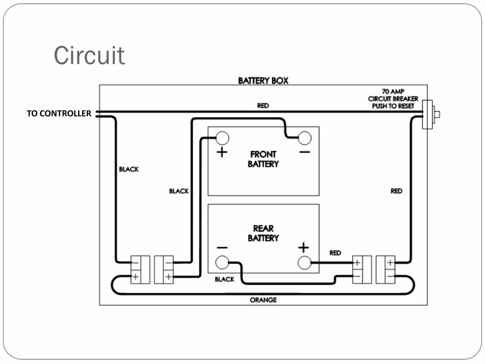
Circuit
TO CONTROLLER

LimitDualSingle
Actuator Joysticks
Actuator Controller
Main Motor Controller
From Battery Box
Auto Actuation circuit

Circuitry The previous highlight the circuitry used for the All Terrain
Power Chair. The batteries are connected in series – 24V The batteries use quick connectors to the circuit for easy
replacement. There will be an auto actuation circuit that will be built to
enable automatic actuation of the seat

Joystick The main joystick controls the chairs motion It has the on/off switch as well and has the main stick used to
control movement It allows for precise movement depending on the tilt of the
joystick Speed control is also available from about 1 mph to the
maximum 7mph There is a bottom charger/programming port

Controller• Penny & Giles Pilot+• Powered via the 24 volt batteries and controls both motors
and receives signals from joystick• The controller can be reprogrammed using a Qtronix
Programmer and connects to the charging port on the joystick.
• There isn’t code that is actually written for convenience

Actuator Linak Actuator Operates with 24V, 4.5A Max Load 4000N Duty Cycle 10% (6min/hr) Adjusts tilt of seat with the use of hinges on the chassis Has its own controller that connects to the main P&G
controller Will be used in auto adjusting circuit

Batteries 2 PowerSonic 12V batteries Group24 75Ahr Capable of powering the chair for the entire day without
slowing down Sealed rechargeable Gel Cell battery for ease of use and
quality

Battery Cage The batteries will sit in the pre-made battery cage of the Quickie
S-626 It is made of steel and is strong enough to support the weight of
each 51 lb battery

Charger Lester Electrical 24V Dual mode automatic battery charger Delivers 8 Amps to charge the batteries Is able to plug directly into any wall socket for ease LED indicators tells the user when the batteries are <80%,
>80% and 100%. Also reports any faults if any

Self Adjusting Actuation Use of an accelerometer (ADXL335) will be used to
determine tilt. With the use of a microcontroller the voltage read from the
accelerometer will be translated into tilt information using AD conversion
The actuator will then adjust accordingly

Schematic
The above circuit will be built and will contain the PIC along with the accelerometer. The wires from the actuator switch will be bypassed into the circuit when the user wants and auto
adjustment will be done.
U2
8051PIC16F874
P1B0T21
P1B1T2EX2
P1B23
P1B34
P1B45
P1B5MOSI6
P1B6MISO7
P1B7SCK8
RST9
P3B0RXD10
P3B1TXD11
P3B4T014
P3B5T115
XTAL218
XTAL119
GND20 P2B0A8 21P2B1A9 22P2B2A10 23P2B3A11 24P2B4A12 25P2B5A13 26P2B6A14 27P2B7A15 28
P0B7AD7 32P0B6AD6 33P0B5AD5 34P0B4AD4 35P0B3AD3 36P0B2AD2 37P0B1AD1 38P0B0AD0 39VCC 40
P3B2INT012
P3B3INT113
P3B6WR16
P3B7RD17
PSEN 29ALEPROG 30EAVPP 31
J2
HDR1X3ADXL335 Accelerometer
J3
HDR1X3OSCILATOR
Q1
2N2222A
Q2
2N2222A
HDR1X23V & Ground
HDR1X3Actuator Joystick
X1LED
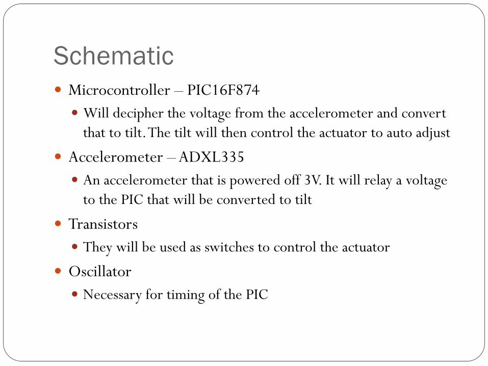
Schematic Microcontroller – PIC16F874 Will decipher the voltage from the accelerometer and convert
that to tilt. The tilt will then control the actuator to auto adjust
Accelerometer – ADXL335 An accelerometer that is powered off 3V. It will relay a voltage
to the PIC that will be converted to tilt
Transistors They will be used as switches to control the actuator
Oscillator Necessary for timing of the PIC

PCB
The above shows what the PCB layout will look like

Tilt Sensor Code The code for the tilt sensor will be written in C and coded
into the PIC The PIC will be responsible for analog to digital conversion
of the accelerometer The tilt will then be calculated and the actuator will be
controlled to accommodate for the tilt When the tilt reaches the critical angle (15º) a buzzer will
sound to indicate the hill is to steep to traverse

Tilt Sensor Code#include <math.h>#include <stdio.h>#include <stdlib.h> #include <pic.h>#include <htc.h>
__CONFIG(DUNPROT & PWRTDIS & XT & WDTDIS & BORDIS & LVPDIS);#ifndef _XTAL_FREQ// Unless already defined assume 4MHz system frequency// This definition is required to calibrate __delay_us() and __delay_ms()#define _XTAL_FREQ 7372800#endif void InitLCD(void);void DisplayC(unsigned char position, const char *str);void DisplayCharacter(unsigned char pos, unsigned char c);float seatlevel,degree,y,volt,ydiff,yg,radians;void Initial(void){
ADCON1 = 0x44; // Select PORTA pins for ADC or digital I/OADCS0 = 1; // Use A/D FOSC/8TRISA = 0x0B;// Set I/O for PORTATRISB = 0xE1; // Set I/O for PORTBTRISC = 0xB7; // Set I/O for PORTCTRISD = 0x00; // Set I/O for PORTDTRISE = 0x04;// Set I/O for PORTEPORTD = 0; // Turn off LEDsInitLCD();
}

Tilt Sensor Code cont.for (;;)
{ADConvert();
if (degree > 90);
P1B1T2EX= 1;return;
elseif(degree < 90);P3B23INT1 =1;return;
{else (degree > 80 && degree >
100);PP2B2A10 = 1return;
}}
}
void ADConvert(void){
CHS0 = 1; // Use channel AN1ADON = 1; // Turn A/D on__delay_us(30); // delay 30 usec to settle A/D acquisitionADGO = 1; // Start conversionwhile ( ADGO ); // wait for ADGO to go off signalling end of conversion
}int main(void){
float volt = (y/1023.0)*3; //3 volt is the power supply , y is the returned value for 10 bits(0-1024)float ydiff = volt/zeroG; //zeroG can be measured using a multimeter at angle =0float yg= ydiff/accelaration;float radian = asin(yg);float degree = (180/PI)*radian;Initial();DisplayC(0x80,"Analog / Digital");

BudgetItem Cost
Quickie S626 Power Chair $100
2 Power Sonic 12V Rechargeable Batteries $150 ea.
Jay J2 Deep Contour Seat Back and Seat Cushion $25
Lester Electrical 24V Dual Mode Battery Charger $20
Harness and Foot Plate $5
Rear Tires $40 ea.
Rear Wheels $18 ea.
Front Tires $40 ea.
Front Wheels $12 ea.
Microcontroller $10
ADXL335 Accelerometer $25
Metal for Fabrication of Joystick rotator and foot plate $25
Miscellaneous Supplies (Screws, nuts, bolts, grease, paint) $50
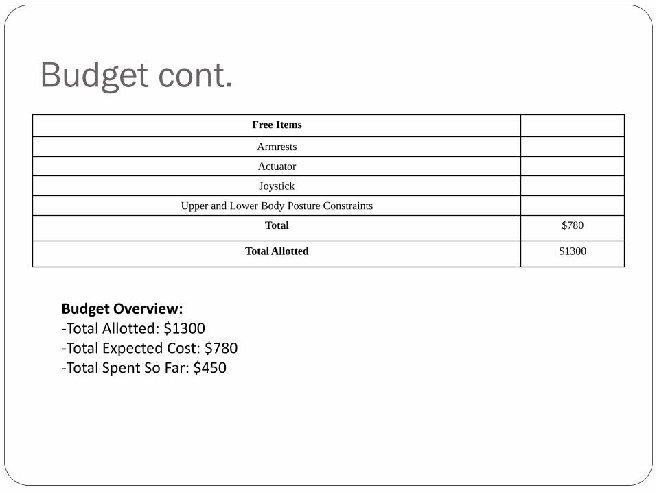
Budget cont.Free Items
Armrests
Actuator
Joystick
Upper and Lower Body Posture Constraints
Total $780
Total Allotted $1300
Budget Overview:-Total Allotted: $1300-Total Expected Cost: $780-Total Spent So Far: $450