the assessment of syngas utilization by fischer tropsch...
TRANSCRIPT

July 2013. Vol. 4, No. 1 ISSN2305-8269
International Journal of Engineering and Applied Sciences © 2012 EAAS & ARF. All rights reserved www.eaas-journal.org
20
THE ASSESSMENT OF SYNGAS UTILIZATION BY FISCHER TROPSCH
SYNTHESIS IN THE SLURRY–BED REACTOR USING Co/SiO2
CATALYST
Bambang Suwondo Rahardjo
Technology Center for Energy Resources Development
Deputy for Information, Energy and Material of Technology
Agency for the Assessment and Application of Technology (BPP Teknologi)
BPPT II Building 22nd
Fl, Jl. M.H. Thamrin No. 8 Jakarta 10340
Email: [email protected]
ABSTRACT
Syngas or synthetic gas is a gas mixture containing CO, CO2 and H2 followed by compound SOx, NOx and CH4 in a
lesser amount of each gas is different depending on feed material, gasifying agent and gasification process. Syngas
can be produced from coal or biomass gasification process at high temperature conditions with the amount of air /
oxygen / steam injection as a controlled gasifying agent. Syngas can be used as intermediate products to produce
other chemicals or burned as an energy source to drive gas engine. In this research discusses the use of syngas from
gasification proceeds through the Fischer-Tropsch Synthesis process as a substitute for synthetic liquid fuel. The
results from the 10 run–times conducted mostly produces gaseous hydrocarbon (HC) light C1~C2 (CH4, C2H6) SNG
equivalent except RUN–02. Gaseous hydrocarbons (HC) light C1~C3 (CH4, C2H6, C3H8) is produced by RUN–01,
RUN–05, RUN–07, RUN–10 (where RUN–03 is relatively small). While RUN–05, RUN–07, RUN–10 are capable of
producing hydrocarbon gases (HC) light C1~C4 (CH4, C2H6, C3H8, n-C4H10 i-C4H10) LPG equivalent. The other 4
run–times (RUN–04, RUN–06, RUN–08, RUN–09) less so produce the desired product. Product hydrocarbon gases
(HC) light C1~C4 are the largest produced by the RUN–05 with N2 gas content is relatively small, in contrast with
the RUN–01, RUN–07, RUN–10 less desirable in the Fischer-Tropsch Synthesis process since the content of N2 gas
is still relatively high. Product hydrocarbon gases (HC) light C1~C3 is the smallest produced by RUN–01 compared
to RUN–05, RUN–07, RUN–10, however, indicated to produce HC chain C > C5 ~C12 (oil), this means that the
smaller the resulting gas products have a tendency to produce more oil. Liquid product produced by RUN–01,
RUN–05, RUN–07, RUN–10 have indicated tendency of products HC chain C > C5~C12 (oil) which is relatively very
small quantity and quality can not be known for sure (equivalent prediction kerosene), since the current vacuum
distillation process (P = 10 mmHg using a solvent reagent C16H34) were bumping.
Keywords : syngas, CoSiO2 catalyst, hexadecane solvent, slurry–bed reactor, F/T synthesis
1. INTRODUCTION
Indonesia as a country endowed with rich variety of
natural resources is time start 'glance' coal or biomass
to be processed either as a source of energy and other
industrial raw materials so as to reduce the 'servings'
of petroleum.
Considered one of the most effective ways to
overcome the energy crisis is through the
development and utilization of alternative energy
resources, such as coal or biomass to the fullest. One
technology that can take advantage of the coal /
biomass into synthetic liquid fuel replacement for
gasoline is technology Gas-To-Liquid (GTL), which
consists of (a) via gasification syngas generation
technology [Coal-To-Gas (CTG) or Biomass-to-Gas
(BTG)] and (b) Fischer-Tropsch Synthesis (FTS).
Fischer-Tropsch Synthesis (FTS) is the process of
converting syngas (CO + H2) which form a long
chain aliphatic compounds HC (CxHy) HC branched
chain, unsaturated HC, and a small amount of
primary alcohol. FTS processes are developed using
fixed-bed reactor can achieve high conversion and
capable of producing optimal parafinis HC class.
System through cracking (cracking), the product can

July 2013. Vol. 4, No. 1 ISSN2305-8269
International Journal of Engineering and Applied Sciences © 2012 EAAS & ARF. All rights reserved www.eaas-journal.org
21
be directed to produce gasoline and diesel fuel types
HC indispensable as a fuel for motor vehicles.
Fischer-Tropsch Synthesis process for converting
syngas into synthetic liquid HC consists of 2 catalytic
reactions that form large molecules of HC from CO
and H2 molecules coal gasification process results /
biomass with oxygen in the feed steam, in which the
product is determined by the use of this kind of
catalyst, H2/CO ratio and reactor operating
conditions.
.
The value of n is very dependent on the method of
making synthetic gas and the type of materials used,
e.g. natural gas H2/CO ratio = 1.8~2.3, coal =
0.6~0.8. Olefin-rich product with a range of 5 ~ 10
(naphtha) Fischer-Tropsch process results in high
temperatures can be used to make synthetic gasoline
and chemicals, contrary to the paraffin-rich product
range of 12 ~ 19 (distillat) results of Fischer-Tropsch
Synthesis process of low-temperature very suitable
for making synthetic diesel and / or wax.
Technological developments GTL (Gas-To-Liquid)
in the world today has reached the commercial stage,
(such as Sasol Ltd.., Shell, ExxonMobil, Rentech
Inc.., Syntroleum Corp., JNOC, etc.) as the holder of
a patent has been successfully operate the GTL
refineries in various parts of the world such as
Nigeria, Egypt, Argentina, Qatar, Iran, Malaysia, and
Australia.
Currently, the Fischer-Tropsch Synthesis process has
been operated commercially in Sasol - South Africa
(coal), Shell in Malaysia (natural gas), ExxonMobil,
Rentech, and Syntroleum. Choren Industries has built
an Fischer–Tropsch plant in Germany that converts
biomass to syngas and fuels using the Shell Fischer–
Tropsch process [6].
In this study focused on the syngas utilization by
Fischer-Tropsch Synthesis using 1L
autoclavemodified slurry-bed reactor with catalyst
(Co/SiO2) and solvent hexadecane into synthetic
liquid fuels instead of fuel oil.
Figure 1. The alternative of syngas utilization as
liquid fuel/synthetic gas and chemicals

July 2013. Vol. 4, No. 1 ISSN2305-8269
International Journal of Engineering and Applied Sciences © 2012 EAAS & ARF. All rights reserved www.eaas-journal.org
22
2. LITERATURE REVIEW
The Fischer–Tropsch process is a collection of
chemical reactions that converts a mixture of CO and
H2 into liquid hydrocarbons. It was first developed
by Franz Fischer and Hans Tropsch at the "Kaiser-
Wilhelm-Institut für Kohleforschung" in Mülhei an
der Ruhr (Germany) in 1925.
The process, a key component of gas to liquids
technology, produces a synthetic lubrication oil and
synthetic fuel, typically from coal, natural gas, or
biomass. The Fischer–Tropsch process has received
intermittent attention as a source of low-sulfur diesel
fuel and to address the supply or cost of petroleum-
derived hydrocarbons.
2.1. Technology Developments
Since the invention of the original process by Fischer
and Tropsch, working at the Kaiser-Wilhelm-Institut
for Chemistry in the 1920s, many refinements and
adjustments have been made. Fischer and Tropsch
filed a number of patents, e.g., U.S. Patent 1,746,464,
applied 1926, published 1930. It was commercialized
by Brabag in Germany in 1936. Being petroleum-
poor but coal-rich, Germany used the Fischer–
Tropsch process during World War II to
produceersatz fuels. Fischer–Tropsch production
accounted for an estimated 9% of German war
production of fuels and 25% of the automobile fuel
[12].
The Fischer–Tropsch process has been applied in
large-scale gas–liquids and coal–liquid facilities such
as Shell's Pearl GTL facility in Ras Laffan, Qatar.
Such large facilities are susceptible to high capital
costs, high operation and maintenance costs, the
uncertain and volatile price of crude oil, and
environmental concerns. In particular, the use of
natural gas as a feedstock becomes practical only
with use of "stranded gas", i.e., sources of natural gas
far from major cities which are impractical to exploit
with conventional gas pipelines and LNG
technology; otherwise, the direct sale of natural gas
to consumers would become much more profitable.
Several companies are developing the process to
enable practical exploitation of so-called stranded gas
reserves.
Conventional FT reactors have been optimized for
massive coal-to-liquids and gas–liquid facilities such
as Shell's Pearl GTL facility. These slurry bed and
fixed-bed reactors are much larger than the sizes
needed for biofuel facilities or for smaller-scale
natural-gas fields. The use of microchannel reactors
scales down the size of the reaction hardware and
overcomes the heat and mass transport problems
associated with conventional FT technology.
Enhanced heat transfer inside the microchannels
reactor allows for optimal temperature control, which
maximizes catalyst activity and life. While no smaller
scale plant is currently in commercial operation,
indications show capital costs, operating costs and
size could all be reduced relative to conventional FT
facilities [15][9]. An order has reportedly been placed
for a 1400-bbl/day modular GTL plant using the
technology of a company called Velocys [11].
In Australia, Linc Energy commenced construction in
1999 of the world's first gas–liquid plant operating on
synthesis gas produced by underground coal
gasification . The GTL plant uses the F-T process,
and produced liquids in 2008. The largest scale
implementation of Fischer–Tropsch technology are in
a series of plants operated by Sasol in South Africa, a
country with large coal reserves, but little oil. The
first commercial plant opening in 1952, 40 miles
south of Johannesburg [14]. Sasol uses coal and now
natural gas as feedstocks and produces a variety of
synthetic petroleum products, including most of the
country's diesel fuel.
In December, 2012 Sasol announced plans to build a
96,000 barrels a day plant in Westlake, Louisiana
using natural gas from tight shale formations in
Louisiana and Texas as feedstock. Costs are
estimated to be between 11 and 12 billion dollars
with $2 billion in tax relief being contributed the state
of Louisiana. The planned complex will include a
refinery and a chemical plant [4].
PetroSA, a South African company which, in a joint
venture, won project innovation of the year award at
the Petroleum Economist Awards in 2008 has the
world's largest Gas to Liquids complexes at Mossel
Bay in South Africa. The refinery is a 36,000 barrels
a day plant that completed semi-commercial
demonstration in 2011, paving the way to begin
commercial preparation. The technology can be used
to convert natural gas, biomass or coal into synthetic
fuels [3].
One of the largest implementations of Fischer–
Tropsch technology is in Bintulu, Malaysia. This
Shell facility converts natural gas into low-sulfur
Diesel fuels and food-grade wax. The scale is 12,000
barrels per day (1,900 m3/d). The new LTFT facility
Pearl GTL which began operation in 2011 at Ras
Laffan, Qatar, uses cobalt catalysts at 230°C,
converting natural gas to petroleum liquids at a rate

July 2013. Vol. 4, No. 1 ISSN2305-8269
International Journal of Engineering and Applied Sciences © 2012 EAAS & ARF. All rights reserved www.eaas-journal.org
23
of 140,000 barrels per day (22,000 m3/d), with
additional production of 120,000 barrels (19,000 m3)
of oil equivalent in natural gas liquidsand ethane. The
first GTL plant in Ras Laffan was commissioned in
2007 and is called Oryx GTL and has a capacity of
34 000 bbl/day. The plant utilizes the Sasol slurry
phase distillate process which uses a cobalt catalyst.
Oryx GTL is a joint venture between Qatar
Petroleum and Sasol.
In October 2006, Finnish paper and pulp
manufacturer UPM announced its plans to produce
biodiesel by the Fischer–Tropsch process alongside
the manufacturing processes at its European paper
and pulp plants, using waste biomass resulting from
paper and pulp manufacturing processes as source
material [13].
A demonstration-scale Fischer–Tropsch plant is
owned and operated by Rentech, Inc., in partnership
with ClearFuels, a company specializing in biomass
gasification. Located in Commerce City, Colorado,
the facility produces about 10 barrels per day (1.6
m3/d) of fuels from natural gas. Commercial-scale
facilities are planned for Rialto, California; Natchez,
Mississippi; Port St. Joe, Florida; and White River,
Ontario [8]. Rentech closed down their pilot plant in
2013, and does not appear to be continuing work on
their FT process and the proposed commercial
facilities.
In the United States, some coal-producing states have
invested in Fischer–Tropsch plants. In Pennsylvania,
Waste Management and Processors, Inc. was funded
by the state to implement Fischer–Tropsch
technology licensed from Shell and Sasol to convert
so-called waste coal (leftovers from the mining
process) into low-sulfur diesel fuel [1].
Table 1. Process developer of Fischer–
Tropsch Synthesis commercial scale
Comp
any
Syngas
Prepar
ation
React
or
FTS
Capa
city
(bpd)
Cata
lyst
Energy
Int. PO (O2)
Slurry
–bed – Co
Exxon CPO
(O2)
Slurry
–bed 200 Co
Rentec
h
PO
(O2),
SR,
ATR
Slurry
–bed 235 Fe
Sasol
PO
(O2),
SR,
Coal
Gasifica
tion
Slurry
–bed 2.500
Fe,
Co
Shell PO (O2)
Fluidi
zed–
bed
110.0
00 Co
Syntrol
eum
ATR
(air)
Fixed
–bed
Fixed
–bed
12.50
0
2
Co
(C)PO : (Catalytic) Partial Oxidation, SR :
Steam Reforming, ATR ; Autothermal
Table 2. Process development of Fischer–Tropsch
Synthesis commercial scale in the world
Countr
y O2
Syngas
Producti
on
FTS
(catalys
t)
Production
Capacity
JOGME
C
(Japan)
not
nee
d
Tubular
Reformer
<Chiyod
a>
Slurry–
bed
(Co)
<NSC>
7 bpd
Pilot
Sasol
(South
Africa) nee
d
Auto
Thermal
Reformer
<Topsoe
>
Slurry–
bed
(Co)
<Sasol>
17.000 bpd
Commercia
l (x2)
Shell
(Malays
ia)
nee
d
POX
<Shell>
Fixed–
Bed
(Co)
<Shell>
3.000 bpd
Commercia
l (x4)
Exxon
Mobil
(USA)
nee
d
Auto
Thermal
Reformer
<Exxon
Mobil>
Slurry–
bed
(Co)
<Exxon
Mobil>
200 bpd
Demonstrat
ion
Conoco
(USA)
nee
d
CPOX
<Conoco
>
Slurry–
bed
(Co)
<Conoc
o>
400 bpd
Demonstrat
ion
BP
(USA)
nee
d
Compact
Reformer
<BP>
Slurry–
bed
(Co)
<BP>
300 bpd
Demonstrat
ion

July 2013. Vol. 4, No. 1 ISSN2305-8269
International Journal of Engineering and Applied Sciences © 2012 EAAS & ARF. All rights reserved www.eaas-journal.org
24
2.2Syngas
Syngas (synthetic gas) as a raw material composed of
a mixture of CO and H2 gas produced through
gasification of biomass / coal and partial oxidation
process of natural gas. Syngas manufacturing process
that has commercial is steam reforming, partial
oxidation and CO2 reforming.
Syngas produced from the biomass gasification has
some impurities formed in the form of inorganic
compounds, such as: NH3, HCl, and H2S, and small
amounts of COS, CS2, and HCN.
Overall FTL system (Fischer Tropsch Liquid) except
the BTL system (Biomass To Liquid) is designed
using a Water-Gas Shift reaction that enough from
syngas with the ratio H2/CO = 1:1 for the total
amount of syngas entering the synthesis reactor FTL.
While the BTL system using H2/CO ratio = 1.8 for
syngas exit gasifier without WGS between gasifier
and synthesis reactor [16]
Influence of impurities contained in the raw syngas,
such as sulfur will poison the catalyst in the syngas
preparation process at high temperature, sulfur will
be converted to H2S or COS. How to cope with
sulfur converted to H2S by adding CaCO3 into the
gasifier or through high-temperature desulfurization
process using ZnO. While COS (carbon oxysulfide)
can be addressed through a hydrolysis process at low
temperature (200oC) using zeolite / alumina that
occurs interaction in molecular absorption of H2S
and H2O, or can be by way of hydrogenation at a
temperature of 750oC.
COS+H_2 O→H_2 S+〖CO〗_2 (exothermic
reaction)
COS+H_2→H_2 S+CO (endothermic reaction)
Table 3. Syngas composition from coal and
biomassa gasification, natural gas
Compositio
n
Syngas
Coal1
Biomass
a2
Natur
al Gas3
Hydrogen
(H2)
14.0
% 18.0% –
Carbon
Monoxide
(CO)
27.0
% 24.0% –
Carbon
Dioxide
(CO2)
4.5% 6.0% –
Oxygen
(O2) 0.6% 0.4% –
Methane
(CH4) 3.0% 3.0% 90.0%
Nitrogen
(N2)
50.9
% 48.6% 5.0%
Ethane
(C2H6) – – 5.0%
HHV
(Btu/scf) 163 135 1,002
1&3Steam - Its generation and use, Babcock
and Wilcox, pp. 5-20 and 5-21 discussion
of coal producer gas. 2HMI International. Data derived from a
fixed–bed updraft gasifier design.

July 2013. Vol. 4, No. 1 ISSN2305-8269
International Journal of Engineering and Applied Sciences © 2012 EAAS & ARF. All rights reserved www.eaas-journal.org
25
Table 4. Requirements of syngas as feedstock Fischer-Tropsch Synthesis
Impurities Range
H2S + COS + CS2 < 1 ppmV
NH3 + HCN < 1 ppmV
HCl + HBr + HF < 10 ppbV
Alkaly metal < 10 ppbV
Solids (soot, ash, dust) Essentially completely
Organic compounds (tar) < dew point
Hetero–atoms (Class 2) < 1 ppmV
2.3. Catalyst
A common catalyst used in the Fischer-Tropsch
Synthesis process is kind of a transition metal that is
Cobalt (Co), Iron (Fe), Ruthenium (Ru) and Nickel
(Ni), but the most commonly used is the Co and Fe
called the Basic Metals.
The Co catalysts is most active and very sensitive to
the presence of sulfur compounds (S which is
poisonous, are able to produce wax. Co catalysts
prepared for the usual raw materials derived from
natural gas with a high content of H2 so much higher
H2/CO ratio so it does not require WGS, when the
syngas feeding with a high H2 content so much
higher H2/CO ratio. SiO2 as a buffer is more
dominant than TiO2 as well as Al2O3
(SiO2>TiO2>Al2O3).. Co catalyst at high pressure
will give effect to the high amount of carbon. Metal
Co as catalyst Fischer-Tropsch Synthesis process
[5].generally dispersed in the buffer material with a
large surface area (alumina, silica, titan, etc..) on
loading of 10 ~ 30 g per 100 g of buffer [10].
Fe catalyst will tend to form some chemical
compounds such as iron oxides and iron carbides
during the reaction. Ferrous metals (Iron / Fe)
suitable to syngas with a low hydrogen content
(H2/CO <1) prepared as lower quality feedstock for
promoting WGS (water gas shift). Fe is more
economical than the Cobalt but susceptible to catalyst
poisons such as sulfur (S).
Ni catalyst make CO hydrogenation to produce the
most of CH4 at high operating temperature
conditions that led to the formation of volatile
carbonyls, thus making this metal is not attractive to
the Fischer-Tropsch Synthesis.
Ru catalyst capable for synthesizing a molecular
weight of the paraffin over 200,000 at high pressure.
From an economic perspective, the use of Ru catalyst
is not very effective because it is much more
expensive than the Cobalt.
Selection of a catalyst based on the ability to
accelerate the reaction between some reaction
(selectivity), has a high activity and efficiency, ease
of regenerated, i.e. the process of restoring the
activity and selectivity of catalysts as they are, and
have chemical stability, thermal and mechanical that
will determine the life of the catalyst.
2.4. Solvent
Solvent function as dissolving in the process of
purification products such as Fischer-Tropsch
Synthesis in the form of slurry is distilled to obtain
the other factions. Table 5 shows the general
characteristics of the type of solvent used and
marketed commercially.

July 2013. Vol. 4, No. 1 ISSN2305-8269
International Journal of Engineering and Applied Sciences © 2012 EAAS & ARF. All rights reserved www.eaas-journal.org
26
Table 5. Characteristic of commercial solvents
Nonane Decane Undecane Dodecane Tridecane Tetradecane Pentadecane Hexadecane
Formula C9H
20 C
10H
22 C
11H
24 C
12H
26 C
13H
28 C
14H
30 C
15H
32 C
16H
34
CAS number [111~84~2] [124~18~5] [1120~21~4] [112~40~3] [629~50~5] [629~59~4] [629~62~9] [544~76~3]
Molar mass (g/mol) 128.26 142.29 156.31 170.34 184.37 198.39 212.42 226.45
Melting point (°C) −53 −30 −26 −9.6 −5 5.5 9.9 18
Boiling point (°C) 151 174 196 216.2 234 253 268~270 287
Density (g/ml) 0.718 0.73 0.74 0.75
0.763 0.769 0.773
Viscosity 20°C (cP) 0.711 0.92
1.35
2.18
3.34
Flash point (°C) 31 46 60 71 102 99 132 135
Autoignition
temp. (°C) 205 210
205
235
201
Explosive limits (%) 0.9~2.9 0.8~2.6
0.45~6.5%
2.5. Reactors
The reactor type of Fischer-Tropsch Synthesis
consists of a slurry-bed, fixed-bed, and fluidized-bed
operated over a temperature range of 150-300°C,
pressure of 0.7-41 bar.
• Three–Phase Fluidized–bed / Ebullating–
bed or Slurry Bubble Column equipped by internal
cooling tubes, wax as support metal-oxides catalyst
particles during the bubble syngas flows to the
bottom of the reactor. Reaction temperature higher
than the boiling point of the FT product called
exothermic reaction. Slurry as fever (heat sink) and
the reactor temperature stabilizer, but because of the
interface between mineral oil slurry with metal-oxide
catalysts, HC formed soluble in the slurry phase,
sucked out the catalyst so that the catalyst activity
increase, decrease oxidation of the catalyst, as well as
stabilizing chain growth. It is cheaper to LTFT (Low
Temperature Fischer Tropsch).
• Multitubular fixed–bed equipped with a
cooler, consisting 1000 of a small tube with a catalyst
as an active catalyst surface (surface active agent) in
the tube, the water surrounding the tube to regulate
the temperature by adjusting the steam pressure.
• Circulating fluidized–bed using a circulating
bed material, recycled gas and cooling gas / solids
circulation used in LTFT.
• Fluidized–bed equipped with a refrigerant
used in HTFT (High Temperatur Fischer–Tropsch)
2.6. Process Condition
Generally, the Fischer–Tropsch process is operated in
the temperature range of 150–300°C. Higher
temperatures lead to faster reactions and higher
conversion rates but also tend to favor methane
production. For this reason, the temperature is usually
maintained at the low to middle part of the range.
Increasing the pressure leads to higher conversion
rates and also favors formation of long-chained
alkanes, both of which are desirable. Typical
pressures range from one to several tens of
atmospheres. Even higher pressures would be
favorable, but the benefits may not justify the
additional costs of high-pressure equipment, and
higher pressures can lead to catalyst deactivation via
coke formation.
A variety of synthesis-gas compositions can be used.
For cobalt-based catalysts the optimal H2:CO ratio is
around 1.8–2.1. Iron-based catalysts promote the
water-gas-shift reaction and thus can tolerate lower
ratios. This reactivity can be important for synthesis
gas derived from coal or biomass, which tend to have
relatively low H2:CO ratios (<1).

July 2013. Vol. 4, No. 1 ISSN2305-8269
International Journal of Engineering and Applied Sciences © 2012 EAAS & ARF. All rights reserved www.eaas-journal.org
27
Table 6. Process condition of Fischer–Tropsch Synthesis by product
H2/CO Katalis
Suhu
(oC)
Tekanan
(bar) Produk
Syn
ga
s
1,0~1,4 Cu–Zn
200~420 51,7~261,99 Ethanol
Cu–Co Campuran alkohol
2,3 Cu–ZnO <250 51,7~261,99 MeOH
DME
Katalis
Zeolith Gasoline
2 Fe 340 23,44 Gasoline
Wax
Hydro–
cracking
Gasoline
Co–K 240 25,51 Diesel
Wax Diesel
2.7. Reaction Mechanism
The conversion of CO to alkanes involves
hydrogenation of CO, the hydrogenolysis (cleavage
with H2) of C-O bonds, and the formation of C-C
bonds. Such reactions are assumed to proceed via
initial formation of surface-bound metal carbonyls.
The CO ligand is speculated to undergo dissociation,
possibly into oxide and carbide ligands [2].
Other potential intermediates are various C-1
fragments including formyl (CHO), hydroxycarbene
(HCOH), hydroxymethyl (CH2OH), methyl (CH3),
methylene (CH2), methylidyne (CH), and
hydroxymethylidyne (COH). Furthermore, and
critical to the production of liquid fuels, are reactions
that form C-C bonds, such as migratory insertion.
Many related stoichiometric reactions have been
simulated on discrete metal clusters, but
homogeneous Fischer–Tropsch catalysts are poorly
developed and of no commercial importance.
Product recovery depends on several factors, among
others: the type of reactor, type of catalyst, the
process parameters [temperature, pressure, residence
time, H2/CO ratio, concentration of reactants (H2,
CO, CO2, H2O)].

July 2013. Vol. 4, No. 1 ISSN2305-8269
International Journal of Engineering and Applied Sciences © 2012 EAAS & ARF. All rights reserved www.eaas-journal.org
28
Main Reaction
Parafin
Olefin
Water gas shift reaction
(2n + 1)H2 + nCO → CnH2n+2 + nH2O
2nH2 + nCO → CnH2n + nH2O
CO + H2O → CO2 + H2
Side Reaction
Alkohol
Boudouard reaction
2nH2 + nCO → CnH2n+2O + (n-1)H2O
2CO → C + CO2
Catalyst Modification
Catalyst oxidation/reduction
Bulk Carbide Formation
MxOy + yH2 → yH2O + xM
MxOy + yCO → yCO2 + xM
yC + xM → MxCy
2.8. Products
Table 7. Fischer–Tropsch Synthesis products
Number of
Carbon Products
Boiling Point
(°C) Utility
C1 ~ C2
C3 ~ C4
SNG
LPG 0~50 Gas tube, Fuel gas, Petrochemicals
C5 ~ C10
C5 ~ C7
C8 ~ C10
Petroleum
Light
Heavy
50~85 Fuel oil
C11 ~ C20
C11 ~ C12
C13 ~ C20
Middle Destillate
Kerosine
Diesel
85~105 Fuel oil
C21 ~ C30
C31 ~ C60
Softwax
Hardwax
105~135
130~300
Fuel oil, Industrial fuel
Lubricants, Wax, Petrochemicals, Asphalt

July 2013. Vol. 4, No. 1 ISSN2305-8269
International Journal of Engineering and Applied Sciences © 2012 EAAS & ARF. All rights reserved www.eaas-journal.org
29
HC light is methane (CH4), ethene (C2H4) and
ethane (C2H6), LPG (C3–C4, propane and butane),
gasoline (C5–C12), diesel fuel (C13–C22), dan wax
(C23–C33).
• Product diesel: require hydrocracking liquid
products Fischer–Tropsch Synthesis to break the
double bond in the catalytic use H2.
• Petroleum refining products: products
Fischer–Tropsch Synthesis which has been
completely cleaned of sulfur, nitrogen, nickel,
vanadium, and asphaltene aromatic.
• Fischer–Tropsch diesel with high cetane
number can be used as a blending component for
improving the quality of diesel fuel.
• Liquid products Fischer–Tropsch Synthesis
is very suitable for fuel cell vehicles.
In general the product distribution of hydrocarbons
formed during the Fischer–Tropsch process follows
an Anderson–Schulz–Flory (ASF) distribution [7]
which can be expressed by formula mentioned below
and shown in Figure 4 and Figure 5.
Wn = The weight fraction of hydrocarbon
molecules containing n carbon atoms (%w).
α = The chain growth probability or the
probability that a molecule will continue reacting to
form a longer chain. In general, α is largely
determined by the catalyst and the specific process
conditions.
Examination of the above equation reveals that
methane will always be the largest single product so
long as alpha is less than 0.5; however, by increasing
α close to one, the total amount of methane formed
can be minimized compared to the sum of all of the
various long-chained products. Increasing α increases
the formation of long-chained hydrocarbons.
The very long-chained hydrocarbons are waxes,
which are solid at room temperature. Therefore, for
production of liquid transportation fuels it may be
necessary to crack some of the Fischer–Tropsch
products. In order to avoid this, some researchers
have proposed using zeolites or other catalyst
substrates with fixed sized pores that can restrict the
formation of hydrocarbons longer than some
characteristic size (usually n<10). This way they can
drive the reaction so as to minimize methane
formation without producing lots of long-chained
hydrocarbons. Such efforts have met with only
limited success.

July 2013. Vol. 4, No. 1 ISSN2305-8269
International Journal of Engineering and Applied Sciences © 2012 EAAS & ARF. All rights reserved www.eaas-journal.org
30
Distribution products of Fischer-Tropsch Synthesis
depends on several parameters, among others: syngas
feed composition, catalyst type, temperature,
pressure, alkali promoter, and buffer. Low
temperatures will influence the amount of carbon
(Carbon Number, CN) is high, but slightly branched
chain or low oxygenate compounds.
3. RESEARCH
The assessment of syngas utilization by Fischer
Tropsch Synthesis using CoSiO2 catalyst in the
autoclave 1L modified slurry–bed reactor conducted
at the Coal Liquefaction Laboratory – PUSPIPTEK -
Serpong.
3.1. Materials
• Mixed–gas (H2:60%, CO:30%, N2:10%)
with H2/CO ratio = 2:1
• Mixed–gas (H2:54%, CO:30%, CH4:10%,
N2:6%) with H2/CO ratio = 1.8:1
• Co/SiO2 catalyst made of Cobalt–based
9.22%Co and Cobalt–based 31.08%Co3O4 from
Co(NO3)2.6H2O (Cobalt Nitrate) with 90.78%SiO2
(nature zeolith) and 68.92%SiO2 (Nacalai zeolith)
respectively as buffer material. The catalysts made by
treatment as follows:
A. Catalyst : Nature zeolith, calcination
(300oC, 2 hours), reduction (300oC, 1 hour)
B. Catalyst : Nature zeolith without treatment
C. Catalyst : Nacalai zeolith, calcination
(300oC, 2 hours), reduction (300oC, 1 hour)
D. Catalyst : Nacalai zeolith, calcination
(200~400oC, 2 hours), reduction (400oC, 6 hours)
• Hexadecane (C16H34) chosen as the solvent
with consideration of characteristics reduce the
formation of CH4 leads to a more severe HC, evenly
distributed heat in the reactor; generate more long-
chain olefin as a result of dissolving ability of HC in
SCFs (super-Critical Fluids) high; overcome
deactivation of the catalyst through heat and mass
transfer better; conditioning the extraction of heavier
HC to come out of the catalyst pores so that it can
extend the catalyst life; H2 increase transfer
capability into the catalyst pores to give more
promoted reaction; and improve the main product
desorption from catalyst pores to avoid further
reaction that will have an impact on product
selectivity
3.2. Equipments
• Autoclave 1L ‘KOBELCO’ (Pmax = 29.42
modified slurry–bed reactor to examine the reactivity
of the catalyst.
• GC–TCD: (Thermal Conductivity Detector)
for the gas products analysis and HC C1~C3
• GC–FID: Flame Ionized Detector for
oxygenates product analysis and HC C2~C30
• Vacuum Distillator separation bottom
product (slurry, HC berat, wax)
• Furnace for catalyst reduction process
• Vacuum Drying Oven for catalyst drying
process.

July 2013. Vol. 4, No. 1 ISSN2305-8269
International Journal of Engineering and Applied Sciences © 2012 EAAS & ARF. All rights reserved www.eaas-journal.org
31
Figure 6. Schematics of equipment system for Fischer-Tropsch Synthesis research scale
3.3. Metodology
3.3.1. Catalyst Preparation
Catalyst preparation carried out due to the difficulty
to obtain FTS catalysts are commercially produced,
by using the following steps:
• Impregnation to deposit metallic Co from
Co(NO3)2.6H2O (Co–Nitrat) into SiO2 as buffer
through drying process in the vacuum dryer at
(100~110oC, 12 hours) in oder to H2O and HNO3
vaporized.
• Calcination to remove the H2O content is
still trapped in the the SiO2 crystal pores by heating
at a temperature of 200~400oC (still below the
melting point) for 2 hours, but in the furnace to
expand the catalyst surface and stabilize heat catalyst.
• Reduction to obtain Co metal in an active
condition by bubbling H2 gas as a reductant inside
plug flow reactor made of stainless steel (ID = 2") at
a temperature of 400oC for 6 hours.
• Characterization performed after calcination
and reduction using X-Ray diffraction spectrum
(XRD) to determine %crystallinity and successful Co
metal impregnation on SiO2 as catalyst support by
looking at the properties treatment effect and the
origin crystal structure to changes in metal Co3O4
into CoO or Co.
• The catalyst reactivity testing carried out
after Co/SiO2 catalyst prepared and characterized
using specific content of Co and reacted with mixed-
gas inside autoclave 1L to investigate the
performance of catalytic reaction that is measured in
the amount of conversion and yield [conversion
mixed-gas (H2/CO) into compound HC].
3.3.2. Fischer–Tropsch Synthesis
The process of converting syngas into liquid HC
products via Fischer-Tropsch Synthesis occurs in the
1L autoclave modified slurry-bed reactor with the
process mechanism as shown in Figure 7.

July 2013. Vol. 4, No. 1 ISSN2305-8269
International Journal of Engineering and Applied Sciences © 2012 EAAS & ARF. All rights reserved www.eaas-journal.org
32
Figure 7. Fischer Tropsch Synthesis mechanism
•
Flashing, by flowing N2 gas and mixed-gas
respectively 2 times at a pressure of 30 bar.
• Leak test, by flowing mixed-gas at a
pressure of 5~6 MPa = 50~60 bar higher than reactor
operating pressure during the contact time = 3 hours.
Whenever there is an indication of a leak pressure>
20 bar.
• Feeding, CoSiO2 catalyst (20 bar, 260-
300oC, 2 hours), C16H34 solvent (1 ml/min), and
mixed gas (50 cm2/gr catalyst).
• Identification of reaction products is done
"on-line" with the GC (steady-state for 10 hours), to
separate the components of compound HC product,
measure the quantity and quality of the components
in the eluent, to calculate the amount of product
conversion yield, analysis of liquid and gas products
qualitatively.
3.3.3. Separation
Gas products carried by flowing through the gas
outlet pressure regulating valve (trap). Heavy HC and

July 2013. Vol. 4, No. 1 ISSN2305-8269
International Journal of Engineering and Applied Sciences © 2012 EAAS & ARF. All rights reserved www.eaas-journal.org
33
slurry products including wax done physically using
the media separator funnel.
3.3.4. Sampling
Sampling of the product carried out after the room
temperature is reached. Product gas through the gas
outlet pressure regulating valve (trap). Liquid product
(bottom products: slurry, heavy HC, wax) from the
trap and distillation.
3.3.5. Analysis
Gas products & HC C1 ~ C3 using GC-TCD.
Oxygenates products and HC C2~C30 using GC-
FID. Oil products using GC-FID-Pyrolizer.
3.3.6. Purification
Vacuum filtration of the liquid products (slurry,
heavy HC including wax). Vacuum distillation of the
slurry product at a pressure of 10 mmHg using a
solvent reagent Hexadecane (C16H34) with a boiling
point of 287°C, in order to obtain other fractions.
Made as wax products produced.
4. RESULT AND DISCUSSION
During the research has been done 10 times RUN
Synthesis Fischer-Tropch use Autoclave 1L modified
slurry-bed reactor at operating conditions (P = 20 bar,
T = 260~300oC, t = 2 hours, r = 900 rpm) with the
following feeding materials:
• Mixed–gas (H2:60%, CO:30%, N2:10%)
with H2/CO ratio = 2:1 for RUN–01, RUN–05,
RUN–07, RUN–10.
• Mixed–gas (H2:54%, CO:30%, CH4:10%,
N2:6%) with H2/CO ratio = 1.8:1 for RUN–02,
RUN–03, RUN–04, RUN–06, RUN–08, RUN–09.
• Catalysts based Co (9.22%Co) from
Co(NO3)2.6H2O with 90.78%SiO2 (nature zeolith)
as a catalyst support for RUN–02, RUN–03, RUN–
04, RUN–06, RUN–08, RUN–09.
• Catalysts based Co (31.08%Co3O4) from
Co(NO3)2.6H2O with 68.92%SiO2 (SiO2 Nacalai)
as a catalyst support for RUN–01, RUN–05, RUN–
07, RUN–10.
• Hexadecane (C16H34) as a solvent for the
whole RUN.
4.1. Result
Product gas is generated each time the RUN analyzed
using GC-TCD and GC-FID to determine the
composition and %volume of gas contained.
4.1.1. Gas Product
Following the GC-TCD and GC-FID analysis results
of standard gas and gas products for-01 RUN, RUN-
05,-07 RUN, RUN-10 were carried out in the
Laboratory of Coal Liquefaction in PUSPIPTEK –
Serpong.
Figure 8. Profile of GC-TCD and GC-FID gas standards RUN-01

July 2013. Vol. 4, No. 1 ISSN2305-8269
International Journal of Engineering and Applied Sciences © 2012 EAAS & ARF. All rights reserved www.eaas-journal.org
34
Figure 9. Profile of GC-TCD and GC-FID gas product RUN-0
Figure 10. Profile of GC-TCD gas standard RUN–05, RUN–07, RUN–10
Figure 11. Profile of GC–TCD and GC–FID product gas RUN–05
July 2013. Vol. 4, No. 1 ISSN2305-8269
International Journal of Engineering and Applied Sciences © 2012 EAAS & ARF. All rights reserved www.eaas-journal.org
35
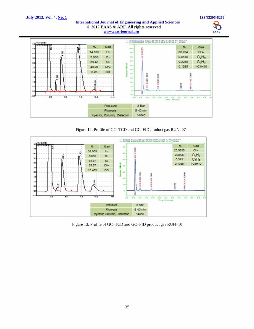
Figure 12. Profile of GC–TCD and GC–FID product gas RUN–07
Figure 13. Profile of GC–TCD and GC–FID product gas RUN–10

July 2013. Vol. 4, No. 1 ISSN2305-8269
International Journal of Engineering and Applied Sciences © 2012 EAAS & ARF. All rights reserved www.eaas-journal.org
36
Table 8. Product gas composition (%volume)
Table 9. Volume of product gas (NL)
4.1.1. Liquid Product
Table 10. Operation condition of GC–FID Pyrolisis
Figure 14. Profile of chromatogram GC–FID feed
and product RUN–01

July 2013. Vol. 4, No. 1 ISSN2305-8269
International Journal of Engineering and Applied Sciences © 2012 EAAS & ARF. All rights reserved www.eaas-journal.org
37
Figure 15. Profile of chromatogram GC–FID feed
and product RUN–05
Figure 16. Profile of chromatogram GC–FID feed
and product RUN–07
Figure 17. Profile of chromatogram GC–FID feed
and product RUN–10
4.2. Discussion
4.2.1. Gas Product
Figure 18 shows the effect of reaction time for each
time the RUN in the Autoclave 1L reactor to a
uniform temperature rise, it means better
performance and a control system stable.
Figure 18. The effect of reaction time against
operation temperatur of autoclave 1L
Table 8 and Table 9 show that of the result 10 times
RUN has done most of the gas producing
hydrocarbons (HC) light C1 ~ C2 (CH4, C2H6) SNG
equivalent except RUN-02. Product hydrocarbon
gases (HC) light C1 ~ C3 (CH4, C2H6, C3H8) is
produced by the RUN-01-05 RUN, RUN-07, RUN-
10 (where the RUN-03 is relatively small). While the
RUN-05, RUN-07, RUN-10 are capable of producing
hydrocarbon gases (HC) light C1 ~ C4 (CH4, C2H6,
C3H8, n-C4H10 i-C4H10). The other 4 RUN (RUN-
04-06 RUN, RUN-08, RUN-09) less so produce the
desired product.
Table 11 shows the material balance RUN-01, RUN-
05, RUN-07, RUN-10, where the RUN-05 is capable
of producing the biggest hydrocarbon gases (HC)
light C1 ~ C4 with N2 gas content is relatively small,
while the product gas hydrocarbons (HC) light C1 ~
C4 generated by the RUN-01 RUN-07, RUN-10 is
relatively small and this case less desirable in the
Fischer-Tropsch Synthesis process because N2 gas
content is still relatively high.
July 2013. Vol. 4, No. 1 ISSN2305-8269
International Journal of Engineering and Applied Sciences © 2012 EAAS & ARF. All rights reserved www.eaas-journal.org
38
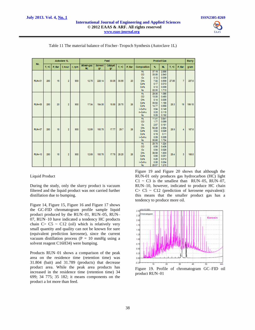
Table 11 The material balance of Fischer–Tropsch Synthesis (Autoclave 1L)
Liquid Product
During the study, only the slurry product is vacuum
filtered and the liquid product was not carried further
distillation due to bumping.
Figure 14, Figure 15, Figure 16 and Figure 17 shows
the GC-FID chromatogram profile sample liquid
product produced by the RUN–01, RUN–05, RUN–
07, RUN–10 have indicated a tendency HC products
chain C> C5 ~ C12 (oil) which is relatively very
small quantity and quality can not be known for sure
(equivalent prediction kerosene), since the current
vacuum distillation process (P = 10 mmHg using a
solvent reagent C16H34) were bumping.
Products RUN–01 shows a comparison of the peak
area on the residence time (retention time) was
31.804 (bait) and 31.789 (products) that decrease
product area. While the peak area products has
increased in the residence time (retention time) 34
699; 34 775; 35 182; it means components on the
product a lot more than feed.
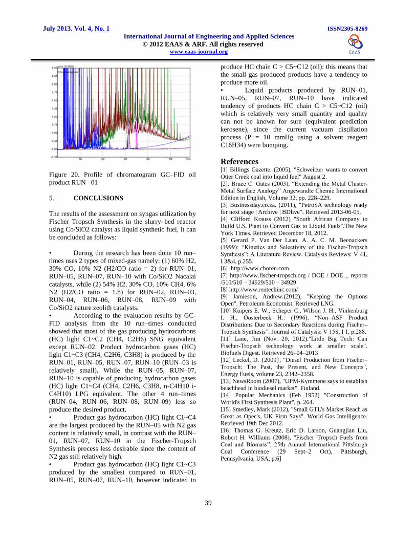
Figure 19 and Figure 20 shows that although the
RUN-01 only produces gas hydrocarbon (HC) light
C1 ~ C3 is the smallest than RUN–05, RUN–07,
RUN–10, however, indicated to produce HC chain
C> C5 ~ C12 (prediction of kerosene equivalent):
this means that the smaller product gas has a
tendency to produce more oil.
Figure 19. Profile of chromatogram GC–FID oil
product RUN–01
July 2013. Vol. 4, No. 1 ISSN2305-8269
International Journal of Engineering and Applied Sciences © 2012 EAAS & ARF. All rights reserved www.eaas-journal.org
39
Figure 20. Profile of chromatogram GC–FID oil
product RUN– 01
5. CONCLUSIONS
The results of the assessment on syngas utilization by
Fischer Tropsch Synthesis in the slurry–bed reactor
using Co/SiO2 catalyst as liquid synthetic fuel, it can
be concluded as follows:
• During the research has been done 10 run–
times uses 2 types of mixed-gas namely: (1) 60% H2,
30% CO, 10% N2 (H2/CO ratio = 2) for RUN–01,
RUN–05, RUN–07, RUN–10 with Co/SiO2 Nacalai
catalysts, while (2) 54% H2, 30% CO, 10% CH4, 6%
N2 (H2/CO ratio = 1.8) for RUN–02, RUN–03,
RUN–04, RUN–06, RUN–08, RUN–09 with
Co/SiO2 nature zeolith catalysts.
• According to the evaluation results by GC-
FID analysis from the 10 run–times conducted
showed that most of the gas producing hydrocarbons
(HC) light C1~C2 (CH4, C2H6) SNG equivalent
except RUN–02. Product hydrocarbon gases (HC)
light C1~C3 (CH4, C2H6, C3H8) is produced by the
RUN–01, RUN–05, RUN–07, RUN–10 (RUN–03 is
relatively small). While the RUN–05, RUN–07,
RUN–10 is capable of producing hydrocarbon gases
(HC) light C1~C4 (CH4, C2H6, C3H8, n-C4H10 i-
C4H10) LPG equivalent. The other 4 run–times
(RUN–04, RUN–06, RUN–08, RUN–09) less so
produce the desired product.
• Product gas hydrocarbon (HC) light C1~C4
are the largest produced by the RUN–05 with N2 gas
content is relatively small, in contrast with the RUN–
01, RUN–07, RUN–10 in the Fischer-Tropsch
Synthesis process less desirable since the content of
N2 gas still relatively high.
• Product gas hydrocarbon (HC) light C1~C3
produced by the smallest compared to RUN–01,
RUN–05, RUN–07, RUN–10, however indicated to
produce HC chain C > C5~C12 (oil): this means that
the small gas produced products have a tendency to
produce more oil.
• Liquid products produced by RUN–01,
RUN–05, RUN–07, RUN–10 have indicated
tendency of products HC chain C > C5~C12 (oil)
which is relatively very small quantity and quality
can not be known for sure (equivalent prediction
kerosene), since the current vacuum distillation
process (P = 10 mmHg using a solvent reagent
C16H34) were bumping.
References [1] Billings Gazette. (2005), "Schweitzer wants to convert
Otter Creek coal into liquid fuel" August 2.
[2]. Bruce C. Gates (2003), “Extending the Metal Cluster-
Metal Surface Analogy” Angewandte Chemie International
Edition in English, Volume 32, pp. 228–229.
[3] Businessday.co.za. (2011), "PetroSA technology ready
for next stage | Archive | BDlive". Retrieved 2013-06-05.
[4] Clifford Krauss (2012) "South African Company to
Build U.S. Plant to Convert Gas to Liquid Fuels".The New
York Times. Retrieved December 18, 2012.
[5] Gerard P. Van Der Laan, A. A. C. M. Beenackers
(1999): “Kinetics and Selectivity of the Fischer-Tropsch
Synthesis”: A Literature Review. Catalysis Reviews: V 41,
I 3&4, p.255.
[6] http://www.choren.com.
[7] http://www.fischer-tropsch.org / DOE / DOE _ reports
/510/510 – 34929/510 – 34929
[8] http://www.rentechinc.com/
[9] Jamieson, Andrew.(2012), "Keeping the Options
Open". Petroleum Economist. Retrieved LNG.
[10] Kuipers E. W., Scheper C., Wilson J. H., Vinkenburg
I. H., Oosterbeek H.: (1996), “Non–ASF Product
Distributions Due to Secondary Reactions during Fischer–
Tropsch Synthesis”. Journal of Catalysis: V 158, I 1, p.288.
[11] Lane, Jim (Nov. 20, 2012)."Little Big Tech: Can
Fischer-Tropsch technology work at smaller scale".
Biofuels Digest. Retrieved 26–04–2013
[12] Leckel, D. {2009}, "Diesel Production from Fischer–
Tropsch: The Past, the Present, and New Concepts",
Energy Fuels, volume 23, 2342–2358.
[13] NewsRoom (2007), "UPM-Kymmene says to establish
beachhead in biodiesel market". Finland.
[14] Popular Mechanics (Feb 1952) "Construction of
World's First Synthesis Plant", p. 264.
[15] Smedley, Mark (2012), "Small GTL's Market Reach as
Great as Opec's, UK Firm Says". World Gas Intelligence.
Retrieved 19th Dec 2012.
[16] Thomas G. Kreutz, Eric D. Larson, Guangjian Liu,
Robert H. Williams (2008), "Fischer–Tropsch Fuels from
Coal and Biomass”, 25th Annual International Pittsburgh
Coal Conference (29 Sept–2 Oct), Pittsburgh,
Pennsylvania, USA, p.6]