the application of various deep mixing · pdf filesettlements of adjacent structures, while...
TRANSCRIPT
THE APPLICATION OF VARIOUS DEEP MIXING METHODS FOR EXCAVATION SUPPORT SYSTEMS
Kenneth B. Andromalos, P.E.1 and Eric W. Bahner, P.E.2
Abstract In a variety of circumstances, the use of deep mixing methods for the construction of excavation support systems is often the method of choice based on design requirements, site conditions/restraints and economics. These circumstances include the presence of adjacent structures that can tolerate minimal lateral movement; the presence of loose unraveling or flowing sands; the need for a competent cutoff wall to prevent the lowering of the adjacent groundwater and its induced settlements of other structures; and the need to simultaneously underpin an adjacent structure, while constructing an excavation support wall. Other systems such as traditional soldier beams and lagging walls would yield unsatisfactory performance, the installation of vibrated or driven sheetpiles could cause vibration induced settlements of adjacent structures, while concrete diaphragm walls are time consuming and expensive. Based on conditions, the use of multiple-auger or single auger deep mixing methods, jet grouting methods, or the combination of several methods may be required. To illustrate applications of deep mixing in a variety of conditions, several case histories are presented. On projects in Wisconsin and Pennsylvania, the multiple auger deep mixing method was successfully utilized to limit lateral movement of adjacent structures, prevent the loss of support due to unraveling soils and control groundwater. On another project in Pennsylvania, a combination of single auger and jet mixing equipment known as HydraMech was successfully utilized to underpin an adjacent historic structure while constructing an excavation support wall immediately adjacent to the structure. Finally, on a project in Ohio, single auger deep mixing and jet grouting was successfully
1 Group Manager, Brayman Construction Corp, Saxonburg, PA, Email: [email protected] 2 Senior Engineer, Gillen Company, Milwaukee, WI, Email: [email protected]
1

used to construct an 8 m (26 ft) deep retaining wall inside an active high precision machine shop where the soil profile consisted of very loose flowing sands overlying a stiff clay with a high water table. Deep Mixing Methods Deep mixing method (DMM) has become a general term to describe a variety of soil mixing techniques to improve soils in-situ. The Federal Highway Administration has suggested the these techniques can be classified based on 1) method of additive injection (i.e. wet or dry injection), 2) method by which additive is mixed (i.e. rotary/mechanical energy or by high pressure jet, and 3) the location of the mixing tool (i.e. near the end of the drilling rods or along a portion of the drilling rods). The application of the DMM for the construction of excavation support systems primarily uses a wet injection method where a typical cement based grout is used as a drilling fluid and as a binder to form a solidified column(s) of soil-cement. Figure 1 shows three common DMM techniques: Deep Soil Mixing (DSM), Shallow Soil Mixing (SSM) and jet grouting. The DSM method utilizes a series of overlapping augers and mechanical mixing shafts. The SSM method uses a single mechanical mixing auger located at the end of the drilling tool (Kelly bar). Jet grouting can be considered a type of soil mixing which utilizes high velocity, 28 to 42 MPa (4,000 to 6,000 psi) backpressure, jets to hydraulically shear the soil and blend a cement grout to form a soil-cement column. Three basic jet grouting systems are available. These systems are: single phase (grout injection only), dual phase (grout + air injection) and triple phase (water + air injection, followed by grout injection).
`
Figure 1. Wet Deep Mixing Methods: DSM, SSM and Jet Grouting
2
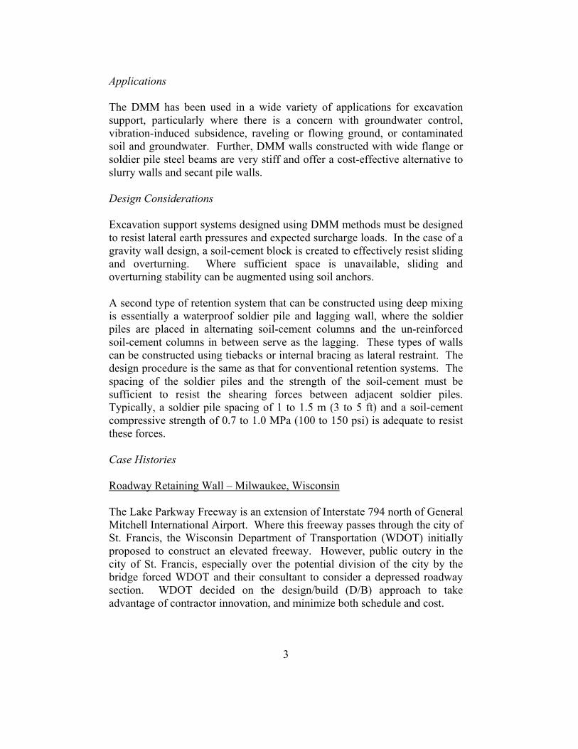
Applications The DMM has been used in a wide variety of applications for excavation support, particularly where there is a concern with groundwater control, vibration-induced subsidence, raveling or flowing ground, or contaminated soil and groundwater. Further, DMM walls constructed with wide flange or soldier pile steel beams are very stiff and offer a cost-effective alternative to slurry walls and secant pile walls. Design Considerations Excavation support systems designed using DMM methods must be designed to resist lateral earth pressures and expected surcharge loads. In the case of a gravity wall design, a soil-cement block is created to effectively resist sliding and overturning. Where sufficient space is unavailable, sliding and overturning stability can be augmented using soil anchors. A second type of retention system that can be constructed using deep mixing is essentially a waterproof soldier pile and lagging wall, where the soldier piles are placed in alternating soil-cement columns and the un-reinforced soil-cement columns in between serve as the lagging. These types of walls can be constructed using tiebacks or internal bracing as lateral restraint. The design procedure is the same as that for conventional retention systems. The spacing of the soldier piles and the strength of the soil-cement must be sufficient to resist the shearing forces between adjacent soldier piles. Typically, a soldier pile spacing of 1 to 1.5 m (3 to 5 ft) and a soil-cement compressive strength of 0.7 to 1.0 MPa (100 to 150 psi) is adequate to resist these forces. Case Histories Roadway Retaining Wall – Milwaukee, Wisconsin The Lake Parkway Freeway is an extension of Interstate 794 north of General Mitchell International Airport. Where this freeway passes through the city of St. Francis, the Wisconsin Department of Transportation (WDOT) initially proposed to construct an elevated freeway. However, public outcry in the city of St. Francis, especially over the potential division of the city by the bridge forced WDOT and their consultant to consider a depressed roadway section. WDOT decided on the design/build (D/B) approach to take advantage of contractor innovation, and minimize both schedule and cost.
3

A permanently tiedback deep mixing method (DMM) wall, was ultimately deemed the quickest and most cost-effective method. An example section of the DMM wall is shown in Figure 2. T yp ica l W all P lan
P R E FAB R IC AT E D W ALL D R AIN (T YP )
S O LD IE R B E AM (T YP .)
W E LD E D S HE AR S T UD S (T YP )R E INFO R C E D
C O NC R E T E W ALL F AC ING
D S M W ALL
1 .37m 1 .37m 1 .37m 1 .37m
Figure 2. Roadway Retaining Wall Cross-Section The project consisted of approximately 912 m of depressed roadway. The alignment is positioned in a railway/utility corridor that runs through a residential area of St. Francis, and is approximately 1000 m west of Lake Michigan. The soil profile consisted of a highly layered profile of fill, clay, silt, and sand underlain by very stiff clay till. These glacial sediments showed no definite pattern of layering. The clay till was located between 6 to 12 m (20 to 40 ft) below the ground surface. Groundwater was measured at depths of 0.6 to 3.7 m in deep in shallow wells along the alignment as part of the original geotechnical investigation. Shallower perched water was also anticipated in areas with sand and silt layers. The design/build documents prepared by the WDOT identified the following criteria for the cutoff wall/retention system design:
• Minimum design life of 75 years. • A maximum groundwater infiltration rate of 6200 liters/day per meter
(500 gpd/lf).
4
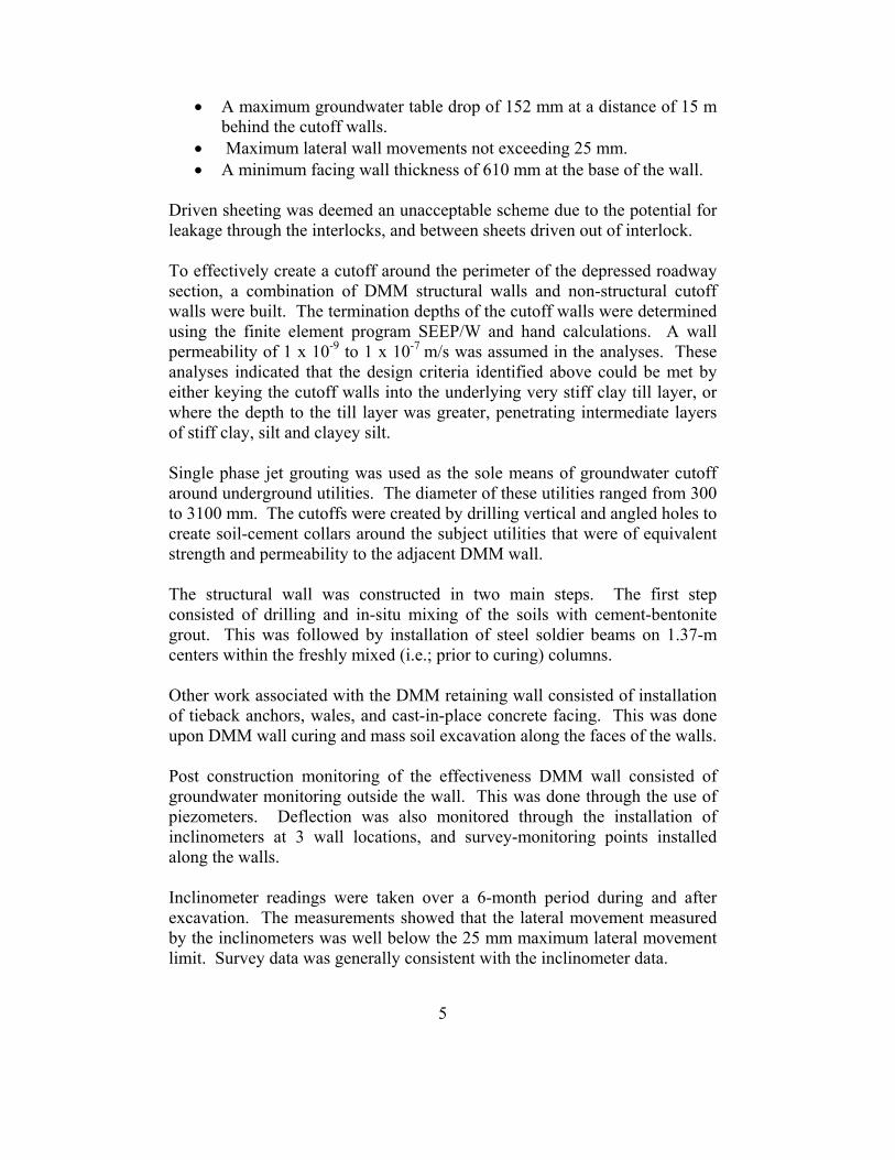
• A maximum groundwater table drop of 152 mm at a distance of 15 m behind the cutoff walls.
• Maximum lateral wall movements not exceeding 25 mm. • A minimum facing wall thickness of 610 mm at the base of the wall.
Driven sheeting was deemed an unacceptable scheme due to the potential for leakage through the interlocks, and between sheets driven out of interlock.
To effectively create a cutoff around the perimeter of the depressed roadway section, a combination of DMM structural walls and non-structural cutoff walls were built. The termination depths of the cutoff walls were determined using the finite element program SEEP/W and hand calculations. A wall permeability of 1 x 10⁻⁹ to 1 x 10⁻⁷ m/s was assumed in the analyses. These analyses indicated that the design criteria identified above could be met by either keying the cutoff walls into the underlying very stiff clay till layer, or where the depth to the till layer was greater, penetrating intermediate layers of stiff clay, silt and clayey silt. Single phase jet grouting was used as the sole means of groundwater cutoff around underground utilities. The diameter of these utilities ranged from 300 to 3100 mm. The cutoffs were created by drilling vertical and angled holes to create soil-cement collars around the subject utilities that were of equivalent strength and permeability to the adjacent DMM wall. The structural wall was constructed in two main steps. The first step consisted of drilling and in-situ mixing of the soils with cement-bentonite grout. This was followed by installation of steel soldier beams on 1.37-m centers within the freshly mixed (i.e.; prior to curing) columns. Other work associated with the DMM retaining wall consisted of installation of tieback anchors, wales, and cast-in-place concrete facing. This was done upon DMM wall curing and mass soil excavation along the faces of the walls. Post construction monitoring of the effectiveness DMM wall consisted of groundwater monitoring outside the wall. This was done through the use of piezometers. Deflection was also monitored through the installation of inclinometers at 3 wall locations, and survey-monitoring points installed along the walls. Inclinometer readings were taken over a 6-month period during and after excavation. The measurements showed that the lateral movement measured by the inclinometers was well below the 25 mm maximum lateral movement limit. Survey data was generally consistent with the inclinometer data.
5

The Lake Parkway project provides an excellent example of the DMM earth retention technique. The approach resulted in the construction of a structurally sound, watertight, and aesthetically pleasing finished wall. DMM provided a notable cost savings over comparable diaphragm wall systems, and resulted in a shorter construction time schedule. Cut and Cover Tunnel – Pennsylvania The Pennsylvania Department of Transportation (PennDOT) planned to connect a new bridge crossing the Susquehanna River to State Route 54 and bypassing the Danville, Pennsylvania business district. The new route passed through the historic district, characterized by spectacular old mansions and a narrow right of way. The new connector, and underpass, replaced an at-grade crossing. Test borings made along the alignment showed that the soil profile consisted of a loose to dense layer of silt, sand and gravel. The ground water level was determined to be below the proposed bottom of the underpass. The historic mansions are 0.9 to 1.2 m (3 to 4 ft) from the pre-construction location of the sidewalks. These 3-story mansions are constructed of brick, stone or stucco, notoriously brittle materials that crack from small movements. PennDOT’s designer, Gannett Fleming, Inc., recognized that the excavation for the underpass needed to limit ground movements to preserve the appearance of the adjacent historic mansions, and therefore, specified an excavation support system consisting of a concrete slurry wall, a secant pile wall or a deep soil mix (DSM) wall. These systems eliminate sloughing of cohesionless soils during excavation, which could result in lateral movements of the adjacent structures. Driving soldier piles or steel sheet piling was not permitted, due to the potential for vibration damage to the adjacent structures. The project had approach sections at each end, and a rigid frame underpass at the deepest portions of the project. The excavation depth ranged from 0 to about 6.7 m (22 ft) in the approach sections to about 9.4 m (31 ft) at the deepest point in the rigid frame section. The designers needed to consider the proximity of the mansions located along the excavation. The support system needed to restrict horizontal and vertical movements resulting from the excavation. The designers realized that controls implemented during construction had the most significant impact on the ensuing deformations. To minimize movement, the following measures were taken to control ground movements:
6

1. Designed the uppermost bracing level near the top of the excavation to limit ground movements resulting from the cantilever condition during the initial excavation.
2. Limited the maximum vertical distance between supports at any time during the excavation to 3.0 m (10 ft).
3. Prestressed the horizontal supports to 100 percent of the design load, except where struts were opposite basement walls.
4. Extended the excavation below a strut level to a maximum of 0.6 m (2 ft) before installing the strut.
5. Did not rely on unexcavated earth berms against the retaining wall for horizontal support, i.e., did not make the excavation along the centerline of the underpass before installing the struts.
The design of the earth retention system played only a part in controlling ground movements. Construction practice had an equal, or even greater significance. The construction practice used for the DSM wall is now described:
The DSM procedure blended the in-situ soils with a cement grout to form a continuous soil-cement interconnected wall on each side of the excavation. The walls were constructed so that the minimum effective wall width was 0.61 m (24 in). The length of each side of the permanent shoring was 186 m (610 lineal ft), for a total of 372 m (1220 ft) of soil-mixed wall. In addition to the soil-mixed wall, steel beams (w18x40 soldier piles) were placed on 1.38 m (4.5 ft) centers into the soilcrete, prior to initial set, to provide sufficient stiffness and lateral reinforcement.
Two samples of cured soil-cement were collected per 15 lineal m (50 lineal ft) of wall. From each cored location, one sample was tested at 28 days for UCS and the remaining sample was stored until the underpass construction was completed. A total of 24 cored samples were collected at randomly selected wall locations. The average compressive strengths of these samples were 3.8 MPa (552 psi).
Contract documents required the contractor to establish a monitoring system to observe the behavior of the excavation support system. Data from the six inclinometers installed between the back of the DSM wall and the mansions were consistent and showed maximum horizontal movements ranging from about 5.6 to 6.9 mm (0.22 to 0.27 in).
The instrumentation data demonstrated that the excavation support system succeeded in limiting ground movements and protecting the adjacent mansions during construction. Ground movements were restricted to the
7

minimum amount observed in previously documented case studies reported by others.
Figure 3. DSM retaining wall supporting adjacent historic structure.
Excavation Support and Underpinning – Coudersport, Pennsylvania In Coudersport, Pennsylvania, the construction of a new addition required an excavation extending to depths of 4.6 to 5.2 m (15 to 17 ft) below the existing footing grade. The earth retention/underpinning system for this project was designed to:
• Stabilize raveling ground conditions at the excavation face • Provide positive support (underpin) of the existing building
foundation • Retain the excavation to allow construction of the new addition
The design incorporated the use of Hydramech deep mixing technology and traditional geotechnical engineering principles. Hydramech is mechanical soil mixing enhanced by jet grouting to provide additional column diameter. This allowed for underpinning of the existing adjacent shallow foundation.
8

The external stability of the structure was determined by the geometry of the soil-cement block. The safety factor against overturning was augmented using passive bar anchors (soil nails) at a set depth and horizontal spacing. Sliding stability was provided by the weight of the block and the applied foundation load, and took advantage of the full internal friction of the foundation soil. Bearing capacity requirements were satisfied by simply extending the deep mixing treatment to a competent bearing layer. Figure 4 shows a cross section of the final wall system.
Figure 4. HydraMech retaining wall cross-section Internal stability of the structure is governed by the unconfined compressive strength of the soil-cement. The soil-cement columns must be strong enough to support the foundation loads, resist horizontal shearing through the column, and resist bending-induced compressive and tensile stresses. The columns must also provide sufficient punching shear resistance at the anchor (nail) heads.
9

Figure 5 shows a completed view of the earth retention/underpinning system.
F ig u re 5 . C o m p le te d re ta in in g w a ll a n d u n d e rp in n in g s ys te m
F i
g u re 5 . C o m p le te d re ta in in g w a ll a n d u n d e rp in n in g s ys te m
Pit Excavation within Existing Structure – Ohio An area within an existing manufacturing facility containing precision machinery required the construction of a new massive machine tool foundation. The foundation soils primarily consisted of loose poorly graded sands, which were prone to piping and settlement from even moderate vibration. A soil-mixed temporary retaining wall system was used to facilitate excavation and construction of the 35 m x 13 m x 8m (114 ft x 44 ft x 27 ft) deep foundation structure. The wall also served as a groundwater seepage barrier during installation of the machine tool foundation. The initial phase of work involved installation of 195 soil mixed columns to create a rectangular wall system. The columns were each 914 mm (36 in) in diameter and spaced on 686 mm (27 in.) centers to create an effective wall thickness of 610 mm (24 in.). A steel beam was installed in every second column (1.2 meters center to center) to provide the required wall system strength. SSM columns and steel beams were installed to within vertical tolerance of 0.5 degrees. The steel beams were embedded to a depth of 4.6 m (15 ft) below the excavation base for toe stability. The SSM columns were extended to a depth of 6 m (20 ft) below base grade to develop sufficient basal stability.
10

The second phase of the project consisted of jet grouting to provide support to existing crane bent foundations adjacent to the retaining wall in areas inaccessible by the SSM rig. Holes were typically placed on 0.6 m (2 ft) centers and grouted using the single stem jet grout method at pressures of 35 MPa (5,000 psi) using a cement grout to yield the required 610 mm (24 in) wall thickness and desired permeability. Pressure and lifting rates varied beneath the crane bents to assure complete contact to the existing concrete bent foundations. Jet grout columns were also installed behind the SSM wall in areas where columns may have deviated more than 0.5 degrees from vertical to provide suitable overlapping of the SSM columns. In-situ samples were taken from the completed soil-mix and jet grouted columns for permeability and compressive strength. Laboratory testing results indicated the SSM material developed an average unconfined compressive strength of 3.3 MPa (226 psi) within 28 days. Hydraulic conductivity results ranged from 1.1 x 10⁻⁸ cm/sec to 2.8 x 10⁻⁶ cm/sec with an average of 8.5 x 10⁻⁷ cm/sec. Figure 6 shows completed view of the retaining wall/seepage barrier.
Figure 6. Exposed pit excavation retaining wall/seepage barrier
Summary and Conclusions In certain circumstances, site constraints and ground conditions innovative earth retention methods using DMM can prove technically superior and more cost effective than more common methods. As demonstrated in this paper, DMM is versatile enough to construct a variety of earth retention schemes.
11

References Andromalos, K.B., Y.A. Hegazy and B. H. Jasperse, 2000, “Stabilization of Soft Soils by Soil Mixing,” Soft Ground Technology Conference, United Engineering Foundation and ASCE Geo-Institute, Noorwijkerout, Netherlands, May 28 – June 2. Bahner, E.W., Naguib, A.M., “Design and Construction of a Deep Soil Mix Retaining Wall for the Lake Parkway Freeway Extenstion”. Elias, V., Welsh, J., Warren, J., Lukas, R., 1998, “Ground Improvement Technical Summaries, Volume II, Demonstration Project 116”, U.S. Department of Transportation, Federal Highway Administration, Publication No. FHWA-SA-98-086, September, 1998. McMahon, D. R., K. L. Fishman, P. Maltese and K. B. Andromalos, 2001, “A DSM Wall for Excavation Support,” 2001: A Geo-Odyssey, Foundations and Ground Improvement, ASCE Geo-Institute and Virginia Tech, Blacksburg, Virginia, June 9 –13.
12