the application of iron based metal organic … · organic frameworks as supercapacitor electrode...
TRANSCRIPT
THE APPLICATION OF IRON BASED METAL ORGANIC FRAMEWORKS AS
SUPERCAPACITOR ELECTRODE MATERIALS
RAHUL FILIPE HONAVAR MELO PIRES DISSERTAÇÃO DE MESTRADO APRESENTADA À FACULDADE DE ENGENHARIA DA UNIVERSIDADE DO PORTO EM ÁREA CIENTÍFICA
M 2017
2 2
Master in Chemical Engineering
The Application of Iron Based Metal Organic Frameworks as Supercapacitor Electrode
Materials
A Master’s dissertation
of
Rahul Filipe Honavar Melo Pires
Developed within the course of dissertation
held in
National Taiwan University – Energy Materials Laboratory
Supervisor at NTU: Professor Nae-Lih Wu
Departamento de Engenharia Química
August of 2017

The Application of Iron Based MOFs as Supercapacitor Electrode Materials
Acknowledgments
To Professor Nae-Lih Wu for kindly giving me the opportunity to work in his laboratory
under his supervision and giving a direction to the project.
To Mozaffar Abdollahifar for guiding me throughout the whole process and for
introducing me to the techniques involved in the experiments.
To all my colleagues in the EML for the advice given and knowledge transmitted during
the time spent working in the lab.
To Professor Madeira, Dcoop and OIA for making the exchange between universities
possible.
To my family and friends for the support.
Thank you!
The Application of Iron Based MOFs as Supercapacitor Electrode Materials
Abstract
Metal-organic frameworks (MOFs) are a versatile class of crystalline materials with
varied applications as a result of their controllable structure, tunable pore size and large
surface area. MOFs were synthesized from ferrous precursors and with 2-methylimidazole and
1,2,4-triazole as organic linkers to be used as supercapacitor electrode materials. In addition
to attempting to reproduce synthesis of ZIF-8 in aqueous medium, three new materials were
synthesized by a solvothermal process: Fe-MeIm-ST1, Fe-MeIm-ST2 and Fe-Trz-ST1. Materials
were characterized using X-ray diffraction analysis, scanning electron microscopy, energy
dispersive X-ray spectroscopy, transmission electron microscopy, nitrogen adsorption and
electrochemical tests both before and after calcination. These were found to contain iron
oxides. Of the three new materials synthesized, the specific capacitance of Fe-MeIm-ST2-V300,
obtained from calcination of Fe-MeIm-ST2, was the highest (157 F/g), when sodium sulfite was
used as an electrolyte, suggesting a possible application as a supercapacitor electrode material.
However there is a need for further modification to increase stability and capacitance. The
other materials produced, in their present form, did not have high capacitance.
Keywords (theme): MOFs; Solvothermal; Supercapacitor; 2-Methylimidazole; 1,2,4-Triazole

The Application of Iron Based MOFs as Supercapacitor Electrode Materials
Declaration
I hereby declare, on my word of honour, that this work is original and that all non-original
contributions were properly referenced with source identification.
Sign and date
The Application of Iron Based MOFs as Supercapacitor Electrode Materials
i
Index
1 Introduction ........................................................................................... 1
1.1 Framing and presentation of the work .................................................... 1
1.2 Aim ................................................................................................ 2
1.3 Energy Materials Laboratory ................................................................. 2
1.4 Contributions of the Work .................................................................... 3
1.5 Organization of the thesis .................................................................... 3
2 State of the Art ....................................................................................... 5
2.1 Classification of Energy Storage Devices and Supercapacitors ........................ 5
2.2 Electrode Materials ............................................................................ 8
2.3 Metal-organic framework ..................................................................... 9
2.3.1 Zeolitic Imidazolate Frameworks .................................................................... 10
2.3.2 Metal 1,2,4-Triazolate Frameworks.................................................................. 11
3 Methods and Materials ............................................................................ 12
3.1 Synthesis of electrode materials .......................................................... 12
3.1.1 Synthesis of ZIF-8 ....................................................................................... 12
3.1.2 Synthesis of Fe-MeIm-ST1 .............................................................................. 13
3.1.3 Synthesis of Fe-MeIm-ST2 .............................................................................. 13
3.1.4 Synthesis of Fe-Trz-ST .................................................................................. 13
3.1.5 Calcination ............................................................................................... 14
3.2 Analysis and Characterization ............................................................. 14
3.2.1 Phase Identification .................................................................................... 14
3.2.2 Microstructure Characterizations .................................................................... 14
3.3 Electrochemical Characterization ........................................................ 15
3.3.1 Preparation of Electrodes ............................................................................. 15
3.3.2 Cyclic Voltammetry ..................................................................................... 15
3.3.3 Chronopotentiometry/Galvanostatic Charge and Discharge .................................... 16
3.4 Surface Area and Pore Structure Analysis ............................................... 17

The Application of Iron Based MOFs as Supercapacitor Electrode Materials
ii
3.5 Thermal Analysis ............................................................................. 17
3.5.1 Thermogravimetric analysis ........................................................................... 17
4 Results and discussion ............................................................................ 18
4.1 Characterization of ZIF-8 ................................................................... 18
4.1.1 Electrochemical Characterization of ZIF-8-C800 .................................................. 19
4.2 Characterization of Fe-MeIm-ST1 ......................................................... 22
4.2.1 Electrochemical Characterization of Fe-MeIm-ST1-C800 ........................................ 27
4.3 Characterization of Fe-MeIm-ST2 ......................................................... 28
4.3.1 Electrochemical Characterization of Fe-MeIm-ST2-V240 ........................................ 29
4.3.2 Electrochemical Characterization of Fe-MeIm-ST2-V300 ........................................ 30
4.4 Characterization of Fe-Trz-ST1 ........................................................... 32
4.4.1 Electrochemical Characterization of Fe-Trz-ST1-V600 ........................................... 35
4.4.2 Electrochemical Characterization of Fe-Trz-ST1-V240 ........................................... 35
5 Conclusions and Future Perspectives .......................................................... 37
Bibliography .............................................................................................. 39
The Application of Iron Based MOFs as Supercapacitor Electrode Materials
iii
Figure 1 – Diagram of an EDLC (adapted from Pandolfo & Hollenkamp, 2006) [5] ............................6
Figure 2- Specific energy and power capabilities of capacitors (electrostatic), electrochemical
capacitors (supercapacitors), batteries and fuel cells [14]. .......................................................8
Figure 3 – Contour plot of the stored energy density E (mW.h/c-3) spanned in the pore width/working
voltage plane. [15] ........................................................................................................9
Figure 4 – Electrical conductivity in M2(DOBDC)(DMF)2, M2(DSBDC)(DMF)2, M2Cl2(BTDD)(DMF)2, and
M(1,2,3-triazolate)2 measured at 300 K, in N2 atmosphere, and in the dark [17]. ........................ 10
Figure 5 – Synthesis Diagram for Fe-MeIm-ST1 ..................................................................... 13
Figure 6 – Configuration of the three electrode cell. ............................................................ 16
Figure 7 – XRD pattern for ZIF-8. ..................................................................................... 18
Figure 8 – SEM image ZIF-8. ............................................................................................ 19
Figure 9 – XRD of ZIF-8-C800. ......................................................................................... 19
Figure 10 – CV of ZIF-8-C800 in 1.0 M Li2SO4 with different voltage windows. .............................. 20
Figure 11 – CV of ZIF-8-C800 in 1.0 M Li2SO4 after 30 cycles. ................................................... 21
Figure 12 - CV of ZIF-8-C800 in 1.0 M Li2SO4 with different scan rates. ...................................... 21
Figure 13 – Specific capacitances of ZIF-8-C800 in 1.0 M Li2SO4 at different scan rates. .................. 22
Figure 14 – Galvanostatic Charge and Discharge curves of ZIF-8-C800 in 1.0 M Li2SO4 with different
current densities. ....................................................................................................... 22
Figure 15 –XRD pattern of Fe-MeIm-ST1. ............................................................................ 23
Figure 16 – SEM images of Fe-MeIm-ST1, on the left at ×20,000 and on the right ×80,000 magnification.
.............................................................................................................................. 23
Figure 17 – Nitrogen adsorption and desorption isotherm for Fe-MeIm-ST1. ................................ 24
Figure 18 – Barrett-Joyner-Halenda pore distribution plot Pore volume distribution of Fe-MeIm-ST1. 24
Figure 19 - XRD pattern of Fe-MeIm-ST1-C800 ..................................................................... 25
Figure 20- SEM images of Fe-MeIm-ST1, on the left at ×5,000 and on the right ×40,000 magnification 26
Figure 21 – Nitrogen adsorption and desorption isotherm for Fe-MeIm-ST1-C800 .......................... 26
Figure 22 – TGA of Fe-MeIm-ST1 ...................................................................................... 27
Figure 23 – CV of Fe-MeIm-ST1-C800 with Li2SO4 of first 50 cycles ............................................ 27
Figure 24 – XRD pattern of Fe-MeIm-ST2 ............................................................................ 28
Figure 25 – SEM images of Fe-MeIm-ST2, on the left at ×18,000 and on the right ×120,000
magnification ............................................................................................................. 29
Figure 26- TEM images of Fe-MeIm-ST2. ............................................................................ 29

The Application of Iron Based MOFs as Supercapacitor Electrode Materials
iv
Figure 27 – CV of Fe-MeIm-ST2-V240 in 1.0 M Na2SO3 with different voltage windows. ................... 30
Figure 28 - Schematics of the proposed pseudocapacitance mechanism involving SO3-/S-2 [26]. ......... 30
Figure 29 – CV of Fe-MeIm-ST2-V300 with 1.0 M Na2SO3 with different voltage windows. ................ 31
Figure 30 -CV of Fe-MeIm-ST2-V300 in 1.0 M Na2SO3 with different scan rates. ............................ 31
Figure 31 - XRD pattern of Fe-Trz-ST1 .............................................................................. 32
Figure 32 - SEM images of Fe-Trz-ST1, on the left at ×1,700 and on the right ×10,000 magnification . 32
Figure 33 – Nitrogen adsorption and desorption isotherm for Fe-Trz-ST1 .................................... 33
Figure 34 – TGA of Fe-Trz-ST1 under nitrogen gas ................................................................ 34
Figure 35 – SEM of Fe-Trz-ST1-V600 at x30,000 magnification .................................................. 34
Figure 36 - CV of Fe-Trz-ST1 with 1.0 M Li2SO4 of the first 3 cycles ........................................... 35
Figure 37 - CV of Fe-Trz-ST1 with 1.0 M Na2SO3 with different voltage windows ........................... 36
The Application of Iron Based MOFs as Supercapacitor Electrode Materials
v
Notation and Glossary
C Capacitance F
A Area of the plates m2
d Separation of plates m
E Energy J
V Potential Difference V
Cavg Specific Capacitance F/g Iavg Average of anodic and cathodic currents A
s Potential scan rate V/s
w Mass of the active material in the electrode g
P Pressure of adsorbed gas
P0 Saturate vapor pressure
V Volume of adsorbed nitrogen cm3/g
Vm Volume if mono-layer adsorbed nitrogen cm3/g
c BET constant
Greek Letters
𝜀𝑟 Relative permittivity in the double layer
𝜀0 Permittivity of free space λ Wavelength
List of Acronyms
EDLC Electric Double Layer Capacitor CV Cyclic Voltammetry MOF Metal-Organic Framework H4DOBDC 2,5-dihydroxybenzene-1,4-dicarboxylic acid DMF N,N-dimethylformamide H4DSBDC 2,5-disulfhydrylbenzene-1,4-dicarboxylicacid H2BTDD bis(1H-1,2,3-triazolo[4,5-b],[4,’5’-i]dibenzo[1,4]dioxin ZIF Zeolitic Imidazolate Framework XRD X-ray Diffraction SEM Scanning electron microscope TEM Transmission electron microscope EDX Energy dispersive X-ray spectroscopy TGA Thermogravimetric analysis MeIm 2-Methylimidazole Trz 1,2,4-Triazole PVDF Polyvinylidene difluoride NMP N-methylpyrrolidone
The Application of Iron Based MOFs as Supercapacitor Electrode Materials
Introduction 1
1 Introduction
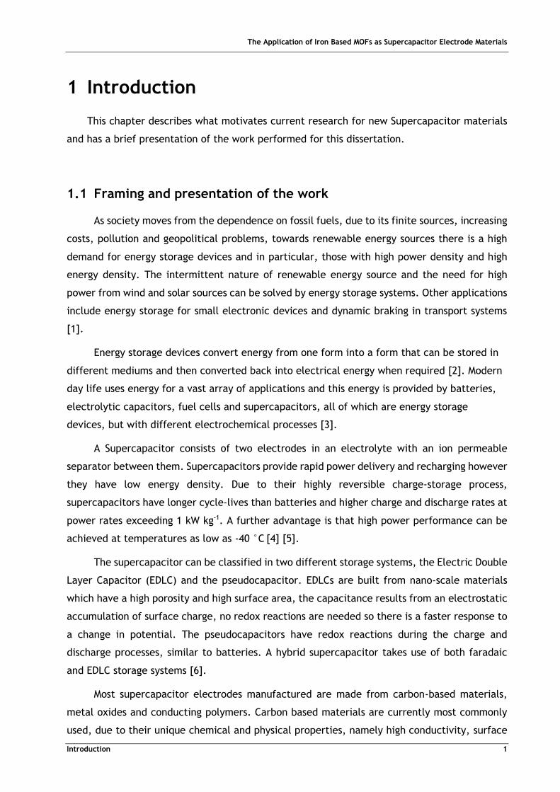
This chapter describes what motivates current research for new Supercapacitor materials
and has a brief presentation of the work performed for this dissertation.
1.1 Framing and presentation of the work
As society moves from the dependence on fossil fuels, due to its finite sources, increasing
costs, pollution and geopolitical problems, towards renewable energy sources there is a high
demand for energy storage devices and in particular, those with high power density and high
energy density. The intermittent nature of renewable energy source and the need for high
power from wind and solar sources can be solved by energy storage systems. Other applications
include energy storage for small electronic devices and dynamic braking in transport systems
[1].
Energy storage devices convert energy from one form into a form that can be stored in
different mediums and then converted back into electrical energy when required [2]. Modern
day life uses energy for a vast array of applications and this energy is provided by batteries,
electrolytic capacitors, fuel cells and supercapacitors, all of which are energy storage
devices, but with different electrochemical processes [3].
A Supercapacitor consists of two electrodes in an electrolyte with an ion permeable
separator between them. Supercapacitors provide rapid power delivery and recharging however
they have low energy density. Due to their highly reversible charge-storage process,
supercapacitors have longer cycle-lives than batteries and higher charge and discharge rates at
power rates exceeding 1 kW kg-1. A further advantage is that high power performance can be
achieved at temperatures as low as -40 °C [4] [5].
The supercapacitor can be classified in two different storage systems, the Electric Double
Layer Capacitor (EDLC) and the pseudocapacitor. EDLCs are built from nano-scale materials
which have a high porosity and high surface area, the capacitance results from an electrostatic
accumulation of surface charge, no redox reactions are needed so there is a faster response to
a change in potential. The pseudocapacitors have redox reactions during the charge and
discharge processes, similar to batteries. A hybrid supercapacitor takes use of both faradaic
and EDLC storage systems [6].
Most supercapacitor electrodes manufactured are made from carbon-based materials,
metal oxides and conducting polymers. Carbon based materials are currently most commonly
used, due to their unique chemical and physical properties, namely high conductivity, surface
The Application of Iron Based MOFs as Supercapacitor Electrode Materials
Introduction 2
area, good corrosion resistance, high temperature stability, controlled pore structure,
processability and compatibily in composite materials [5]. In addition their cheap price and
established production processes make them more accessible [1], [6]. Carbon materials
currently used are activated carbons, carbide derived carbons, carbon nano-tubes, graphene
and mesoporous carbons [1].
Metal organic frameworks (MOFs) first defined by Yaghi and Hailian are a class of
crystalline porous materials which are made up from metal-containing units and organic linkers
[7]. Their importance arises from their ability to reversibly bind molecules and ions within their
channels [8]. By varying the metal containing units and characteristics of the organic linkers,
different MOFs can be created. These materials have gained interest during the past two
decades because of their high surface area, controllable structures and tunable pore size [8].
Their applications in gas storage and separation, sensors, catalysis, drug delivery and
electrochemical systems are being explored [8] [9].
1.2 Aim
The main objective of this dissertation project was to produce a MOF with Iron containing
units and to test its applicability as an electrode material for supercapacitors. In order to do
this, the process of solvothermal synthesis with methanol was utilized.
The materials synthesized were characterized with X-ray diffraction, scanning electron
microscopy, transmission electron microscopy, energy dispersive X-ray spectroscopy and
thermogravimetric analysis and finally electrochemically tested.
1.3 Energy Materials Laboratory
The Energy Materials Laboratory where this work was carried out is located in the
Chemical Engineering Department of the National Taiwan University, Taipei, Taiwan. The
research interest of the laboratory is in the electrochemical field, focused on but not limited
to Lithium-ion batteries and Supercapacitors. Researchers at the Energy Materials Laboratory
consist of group leader Professor Nae-Lih Wu, 2 post doctorate researchers, 2 PhD students,
and several masters and undergraduate students. The laboratory cooperates with institutes
including the Industrial Technology Research Institute and the National Science Council of
Taiwan.
The Application of Iron Based MOFs as Supercapacitor Electrode Materials
Introduction 3
1.4 Contributions of the Work
The objective of this dissertation is to create new materials which can be used as
electrodes for supercapacitors. During the time I spent at the Energy Materials Laboratory I
have applied solvothermal and hydrothermal methods for making MOFs, in attempting to create
new MOFs and testing their electrochemical performance and to assess their potential
supercapacitor applicability, using pre-existing methods already developed in the Laboratory
which include the three electrode test for cyclic voltammetry and galvanostatic charge and
discharge tests.
1.5 Organization of the thesis
The Thesis is divided into six chapters: Introduction, State of the Art, Materials and
Methods, Results and Discussion and Conclusions.
Chapter 1: In the Introduction a brief description is given of the context, scope and
significance of energy storage devices.
Chapter 2: The State of the Art covers the different covers basic concepts about
supercapacitors and Metal Organic Frameworks which are relevant to this work.
Chapter 3: Methods and Materials describes the materials, including chemicals used and all
the experimental procedures performed.
Chapter 4: In the Results and Discussion, all of the obtained results of the characterization
tests and electrochemical tests are presented and discussed.
Chapter 5: In Conclusions and Future Perspectives, a summary of the results and their
interpretation is given along with suggestions for further projects to modify the characteristics
of the electrode material.

The Application of Iron Based MOFs as Supercapacitor Electrode Materials
Results and Discussion 5
2 State of the Art
This chapter will go through a few basic concepts of the Supercapacitor and Metal Organic
Frameworks.
2.1 Classification of Energy Storage Devices and Supercapacitors
The battery is regarded as the primary energy storage device and consists of an
electrochemical cell which produce electricity with a desired voltage from an electrochemical
reaction. Each cell contains two electrodes, the anode which is the negative electrode and the
cathode, the positive electrode with an electrolyte which can be in liquid or solid state. A cell
can bi-directionally convert energy between electrical and chemical energy. The charge storage
mechanism is through bulk mass transfer between electrodes during both charge and discharge.
During discharging, the electrochemical reactions occur at the anodes and the cathodes
simultaneously. To the external circuit, electrons are provided from the anode and are
collected at the cathode. The advantage of the battery is that it has high energy capacity and
even energy discharge. Disadvantages include incapacity to bear high power delivery and
lengthy recharging times. Careful disposal of batteries is required as most contain toxic
materials [3] [10].
A fuel cell is an electrochemical cell which derives its energy from combustible substances
for example hydrogen and methanol [10].
The electrolytic capacitor consists of two electrical conductors separated by a thin
insulator called a dielectric. During charging, energy is stored in the dielectric material in an
electrostatic field [2] [11]. Because of its small size and low capacitance, it is used in integrated
chips and transistors.
The supercapacitor is a category of energy storage device. Composed of two electrodes,
an electrolyte and a separator that electrically isolates the two electrodes. The electrode
materials have a combination of physical and chemical properties, high conductivity, high
surface area, controlled pore structure, good corrosion resistance and high temperature
stability [5].
In an EDLC, when a voltage is applied, charges are electrostatically separated and an
electric double layer is formed at the interface of the electrode and electrolyte. In the double
layer capacitance is created when an excess of electric charges accumulates at the electrode
surface, on the electrolyte side opposite charged ions counterbalance at the surface to reach
electroneutrality. Within the electrolyte, cations move towards the negative electrode and
The Application of Iron Based MOFs as Supercapacitor Electrode Materials
Results and Discussion 6
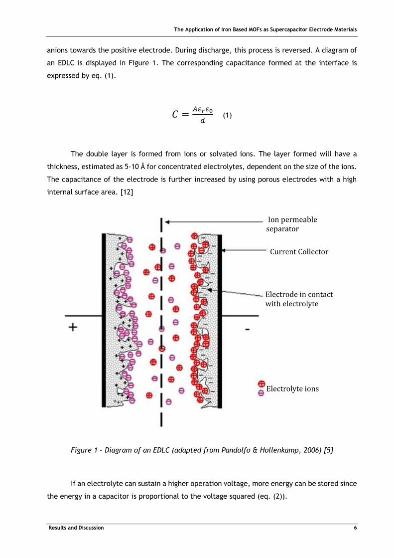
anions towards the positive electrode. During discharge, this process is reversed. A diagram of
an EDLC is displayed in Figure 1. The corresponding capacitance formed at the interface is
expressed by eq. (1).
𝐶 =𝐴𝜀𝑟𝜀0
𝑑 (1)
The double layer is formed from ions or solvated ions. The layer formed will have a
thickness, estimated as 5-10 Å for concentrated electrolytes, dependent on the size of the ions.
The capacitance of the electrode is further increased by using porous electrodes with a high
internal surface area. [12]
If an electrolyte can sustain a higher operation voltage, more energy can be stored since
the energy in a capacitor is proportional to the voltage squared (eq. (2)).
Ion permeable separator
Current Collector
Electrode in contact with electrolyte
Electrolyte ions
Figure 1 – Diagram of an EDLC (adapted from Pandolfo & Hollenkamp, 2006) [5]
The Application of Iron Based MOFs as Supercapacitor Electrode Materials
Results and Discussion 7
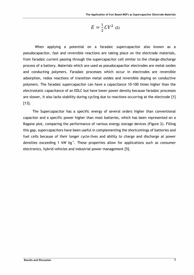
𝐸 =1
2𝐶𝑉2 (2)
When applying a potential on a faradaic supercapacitor also known as a
pseudocapacitor, fast and reversible reactions are taking place on the electrode materials,
from faradaic current passing through the supercapacitor cell similar to the charge-discharge
process of a battery. Materials which are used as pseudocapacitor electrodes are metal oxides
and conducting polymers. Faradaic processes which occur in electrodes are reversible
adsorption, redox reactions of transition metal oxides and reversible doping on conductive
polymers. The faradaic supercapacitor can have a capacitance 10-100 times higher than the
electrostatic capacitance of an EDLC but have lower power density because faradaic processes
are slower, it also lacks stability during cycling due to reactions occurring at the electrode [1]
[13].
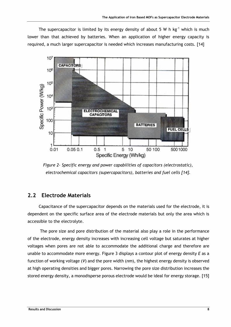
The Supercapacitor has a specific energy of several orders higher than conventional
capacitor and a specific power higher than most batteries, which has been represented on a
Ragone plot, comparing the performance of various energy storage devices (Figure 2). Filling
this gap, supercapacitors have been useful in complementing the shortcomings of batteries and
fuel cells because of their longer cycle-lives and ability to charge and discharge at power
densities exceeding 1 kW kg-1. These properties allow for applications such as consumer
electronics, hybrid vehicles and industrial power management [5].
The Application of Iron Based MOFs as Supercapacitor Electrode Materials
Results and Discussion 8
The supercapacitor is limited by its energy density of about 5 W h kg-1 which is much
lower than that achieved by batteries. When an application of higher energy capacity is
required, a much larger supercapacitor is needed which increases manufacturing costs. [14]
2.2 Electrode Materials
Capacitance of the supercapacitor depends on the materials used for the electrode, it is
dependent on the specific surface area of the electrode materials but only the area which is
accessible to the electrolyte.
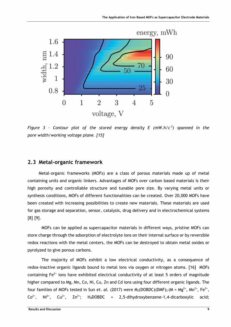
The pore size and pore distribution of the material also play a role in the performance
of the electrode, energy density increases with increasing cell voltage but saturates at higher
voltages when pores are not able to accommodate the additional charge and therefore are
unable to accommodate more energy. Figure 3 displays a contour plot of energy density E as a
function of working voltage (V) and the pore width (nm), the highest energy density is observed
at high operating densities and bigger pores. Narrowing the pore size distribution increases the
stored energy density, a monodisperse porous electrode would be ideal for energy storage. [15]
Figure 2- Specific energy and power capabilities of capacitors (electrostatic),
electrochemical capacitors (supercapacitors), batteries and fuel cells [14].
The Application of Iron Based MOFs as Supercapacitor Electrode Materials
Results and Discussion 9
Figure 3 – Contour plot of the stored energy density E (mW.h/c-3) spanned in the
pore width/working voltage plane. [15]
2.3 Metal-organic framework
Metal-organic frameworks (MOFs) are a class of porous materials made up of metal
containing units and organic linkers. Advantages of MOFs over carbon based materials is their
high porosity and controllable structure and tunable pore size. By varying metal units or
synthesis conditions, MOFs of different functionalities can be created. Over 20,000 MOFs have
been created with increasing possibilities to create new materials. These materials are used
for gas storage and separation, sensor, catalysis, drug delivery and in electrochemical systems
[8] [9].
MOFs can be applied as supercapacitor materials in different ways, pristine MOFs can
store charge through the adsorption of electrolyte ions on their internal surface or by reversible
redox reactions with the metal centers, the MOFs can be destroyed to obtain metal oxides or
pyrolyzed to give porous carbons.
The majority of MOFs exhibit a low electrical conductivity, as a consequence of
redox-inactive organic ligands bound to metal ions via oxygen or nitrogen atoms. [16] MOFs
containing Fe2+ ions have exhibited electrical conductivity of at least 5 orders of magnitude
higher compared to Mg, Mn, Co, Ni, Cu, Zn and Cd ions using four different organic ligands. The
four families of MOFs tested in Sun et. al. (2017) were M2(DOBDC)(DMF)2 (M = Mg2+, Mn2+, Fe2+,
Co2+, Ni2+, Cu2+, Zn2+; H4DOBDC = 2,5-dihydroxybenzene-1,4-dicarboxylic acid;

The Application of Iron Based MOFs as Supercapacitor Electrode Materials
Results and Discussion 10
DMF = N,N-dimethylformamide), M2(DSBDC)(DMF)2 (M = Mn2+, Fe2+;
H4DSBDC = 2,5-disulfhydrylbenzene-1,4-dicarboxylicacid), M2Cl2(BTDD)(DMF)2 (M = Mn2+, Fe2+,
Co2+, Ni2+; H2BTDD = bis(1H-1,2,3-triazolo[4,5-b],[4,’5’-i]dibenzo[1,4]dioxin), and
M(1,2,3-triazolate)2 (M = Mg2+, Mn2+, Fe2+, Co2+, Cu2+, Zn2+, Cd2+) (Figure 4) [17].
Figure 4 – Electrical conductivity in M2(DOBDC)(DMF)2, M2(DSBDC)(DMF)2,
M2Cl2(BTDD)(DMF)2, and M(1,2,3-triazolate)2 measured at 300 K, in N2 atmosphere, and in
the dark [17].
2.3.1 Zeolitic Imidazolate Frameworks
ZIF is a sub-family of MOFs formed from coordination of metal ions and imidazole
derivatives. The metal-imidazole-metal bond forms an angle of 145°, the same angle as the
silicon-oxygen-silicon bond in zeolites [18].
Commercially available ZIF-8 (Zn(MeIm)2) is synthesized from zinc and
2-methyl-imidazole, and it is used as a core for core-shell materials and as a N-containing
carbon precursor [19] [20]. ZIF-8 crystals derived carbon has a high nitrogen content and high
surface area, but its conductivity is limited due to its amorphous nature. In contrast pyrolysis
of ZIF-67 (Co(MeIm)2) will have a graphitic structure with sacrificed nitrogen content [20].
Synthesis of ZIF-8 has been reported in both solvothermal processes or in aqueous systems [21].

The Application of Iron Based MOFs as Supercapacitor Electrode Materials
Results and Discussion 11
2.3.2 Metal 1,2,4-Triazolate Frameworks
Having three N-donors 1,2,4-triazolates can behave like imidazolates to form similar
structural units or isostructural 3D units. [22]
Metal triazolates have gained interest due to their spin crossover behavior and due to short
metal-metal distances in framework which should result in a high charge hopping probability
[23].
The Application of Iron Based MOFs as Supercapacitor Electrode Materials
Results and Discussion 12
3 Materials and Methods
Description of the materials, including chemicals used and all the experimental procedures
performed.
3.1 Synthesis of electrode materials
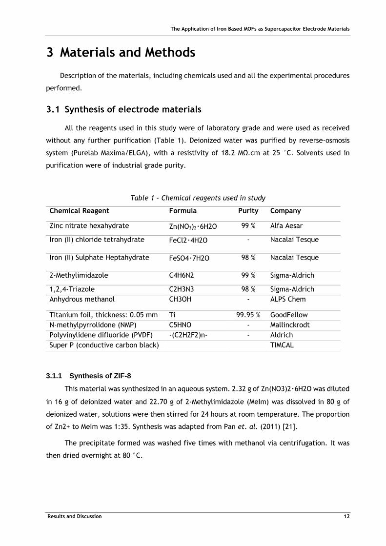
All the reagents used in this study were of laboratory grade and were used as received
without any further purification (Table 1). Deionized water was purified by reverse-osmosis
system (Purelab Maxima/ELGA), with a resistivity of 18.2 MΩ.cm at 25 °C. Solvents used in
purification were of industrial grade purity.
Table 1 – Chemical reagents used in study
Chemical Reagent Formula Purity Company
Zinc nitrate hexahydrate Zn(NO3)2‧6H2O 99 % Alfa Aesar
Iron (II) chloride tetrahydrate FeCl2‧4H2O
- Nacalai Tesque
Iron (II) Sulphate Heptahydrate FeSO4‧7H2O
98 % Nacalai Tesque
2-Methylimidazole C4H6N2 99 % Sigma-Aldrich
1,2,4-Triazole C2H3N3 98 % Sigma-Aldrich
Anhydrous methanol CH3OH - ALPS Chem
Titanium foil, thickness: 0.05 mm Ti 99.95 % GoodFellow
N-methylpyrrolidone (NMP) C5HNO - Mallinckrodt
Polyvinylidene difluoride (PVDF) -(C2H2F2)n- - Aldrich
Super P (conductive carbon black) TIMCAL
3.1.1 Synthesis of ZIF-8
This material was synthesized in an aqueous system. 2.32 g of Zn(NO3)2‧6H2O was diluted
in 16 g of deionized water and 22.70 g of 2-Methylimidazole (MeIm) was dissolved in 80 g of
deionized water, solutions were then stirred for 24 hours at room temperature. The proportion
of Zn2+ to MeIm was 1:35. Synthesis was adapted from Pan et. al. (2011) [21].
The precipitate formed was washed five times with methanol via centrifugation. It was
then dried overnight at 80 °C.
The Application of Iron Based MOFs as Supercapacitor Electrode Materials
Results and Discussion 13
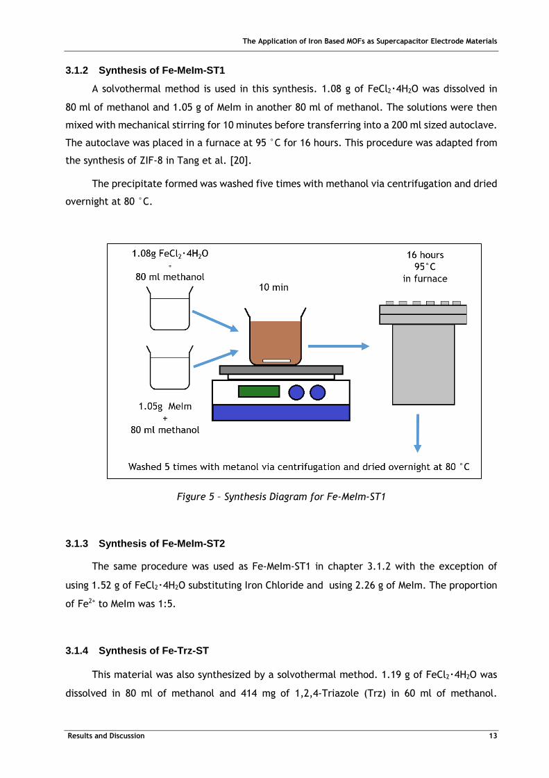
3.1.2 Synthesis of Fe-MeIm-ST1
A solvothermal method is used in this synthesis. 1.08 g of FeCl2‧4H2O was dissolved in
80 ml of methanol and 1.05 g of MeIm in another 80 ml of methanol. The solutions were then
mixed with mechanical stirring for 10 minutes before transferring into a 200 ml sized autoclave.
The autoclave was placed in a furnace at 95 °C for 16 hours. This procedure was adapted from
the synthesis of ZIF-8 in Tang et al. [20].
The precipitate formed was washed five times with methanol via centrifugation and dried
overnight at 80 °C.
Figure 5 – Synthesis Diagram for Fe-MeIm-ST1
3.1.3 Synthesis of Fe-MeIm-ST2
The same procedure was used as Fe-MeIm-ST1 in chapter 3.1.2 with the exception of
using 1.52 g of FeCl2‧4H2O substituting Iron Chloride and using 2.26 g of MeIm. The proportion
of Fe2+ to MeIm was 1:5.
3.1.4 Synthesis of Fe-Trz-ST
This material was also synthesized by a solvothermal method. 1.19 g of FeCl2‧4H2O was
dissolved in 80 ml of methanol and 414 mg of 1,2,4-Triazole (Trz) in 60 ml of methanol.
The Application of Iron Based MOFs as Supercapacitor Electrode Materials
Results and Discussion 14
Proportion of Fe2+ to Trz was 1:1. The solutions were mixed together and stirred for 10 minutes
and transferred into an autoclave.
The precipitate formed was washed five times with methanol via centrifugation and dried
overnight at 80 °C.
3.1.5 Calcination
Materials were calcined in different conditions (table 2) either under vacuum or with
nitrogen gas flow. Temperature of the furnace was raised at a rate of 1 °C/min and held at
calcination temperature for 3 hours before returning to room temperature.
Table 2 – Conditions used for Calcination
Material Gas Temperature (°C)
ZIF-8-C800 ZIF – 8 Nitrogen 800
Fe-Me Im-ST1-C800 Fe-MeIm-ST1 Nitrogen 800
Fe-MeIm-ST2-V300 Fe-MeIm-ST2 Vacuum 300
Fe-MeIm-ST2-V240 Fe-MeIm-ST2 Vacuum 240
Fe-MeTrz-ST1-V600 Fe-Trz-ST1 Vacuum 600
Fe-MeTrz-ST1-V300 Fe-Trz-ST1 Vacuum 240
3.2 Analysis and Characterization
3.2.1 Phase Identification
Phase Identification is carried out by X-ray diffraction (XRD) analysis, which is used to
determine constituents and crystalline phases. The XRD was performed on the diffractometer
(X’pert/Philips) with Cu Kα radiation (λ = 1.418 Å). The X-Ray generator equipped with a
graphite monochromator was operated at 40 kV and 40 mA. The width angle of solar and
divergent slits is 1.0 °. In addition, the reflection data of powder samples was mostly collected
under a continuous¬scanned θ - 2θ mode at a scan-rate of 4 °/min. The scan range is in the
range of 5 ° - 80 °.
3.2.2 Microstructure Characterizations
Surface morphology of the particle samples and films was on a field-emission scanning
electron microscope (FEI Nova NanoSEM 230 and LEO 1530). The powder samples were dispersed
in a methanol solution under sonification and deposited on a copper foil which was then dried
on a hotplate. The samples were dried overnight with vacuum. Before examination, the samples

The Application of Iron Based MOFs as Supercapacitor Electrode Materials
Results and Discussion 15
were coated with gold by ion sputter. The accelerated voltage of electron gun was 5 and 20
kV, respectively. The signals detected secondary electrons and back-scattered electrons.
Transmission electron microscopy (TEM) analysis was carried out using an electron
microscope (H7100/Hitachi) operated at 100 kV. The particles were ultrasonically dispersed
in methanol and a drop of dilute solution was placed on a carbon supported copper grid.
3.3 Electrochemical Characterization
3.3.1 Preparation of Electrodes
The Titanium-based electrodes were prepared via solvent-casting method. First, the
active material was grinded with Super P, a conductive carbon black using a mortar and pestle.
Once the ground powders were homogeneous, a binder (Polyvinylidene fluoride) in a
N-methylpyrrolidone (NMP) solvent was added to the ground powder. After stirring for
10 minutes the slurry is cast on a Titanium strip and spread. The electrodes were heated at
110 °C for 6 hours under vacuum to remove the solvent. After heating, the electrodes were cut
into 1 cm width pieces, with the active material covering 1 cm2 of the strip.
Table 3 – Recipe for working electrodes
Material Weight Percentage (%)
Active Material 80
Super P 10
PVDF 10
3.3.2 Cyclic Voltammetry
This convenient and sensitive method is used to distinguish electrochemical
characteristics of device. An Ideal EDLC’s voltammogram shows a rectangular shaped profile.
For a pseudocapacitor, superficial faradaic reactions happen during the charging or discharging
and some redox peaks appear in the voltammogram. In a real situation the profile is affected
by the resistance of the electrolyte and the contact resistance between the active material and
the current collector, this delays the response, which leads to a slant of the cyclic
voltammogram (CV).
The Application of Iron Based MOFs as Supercapacitor Electrode Materials
Results and Discussion 16
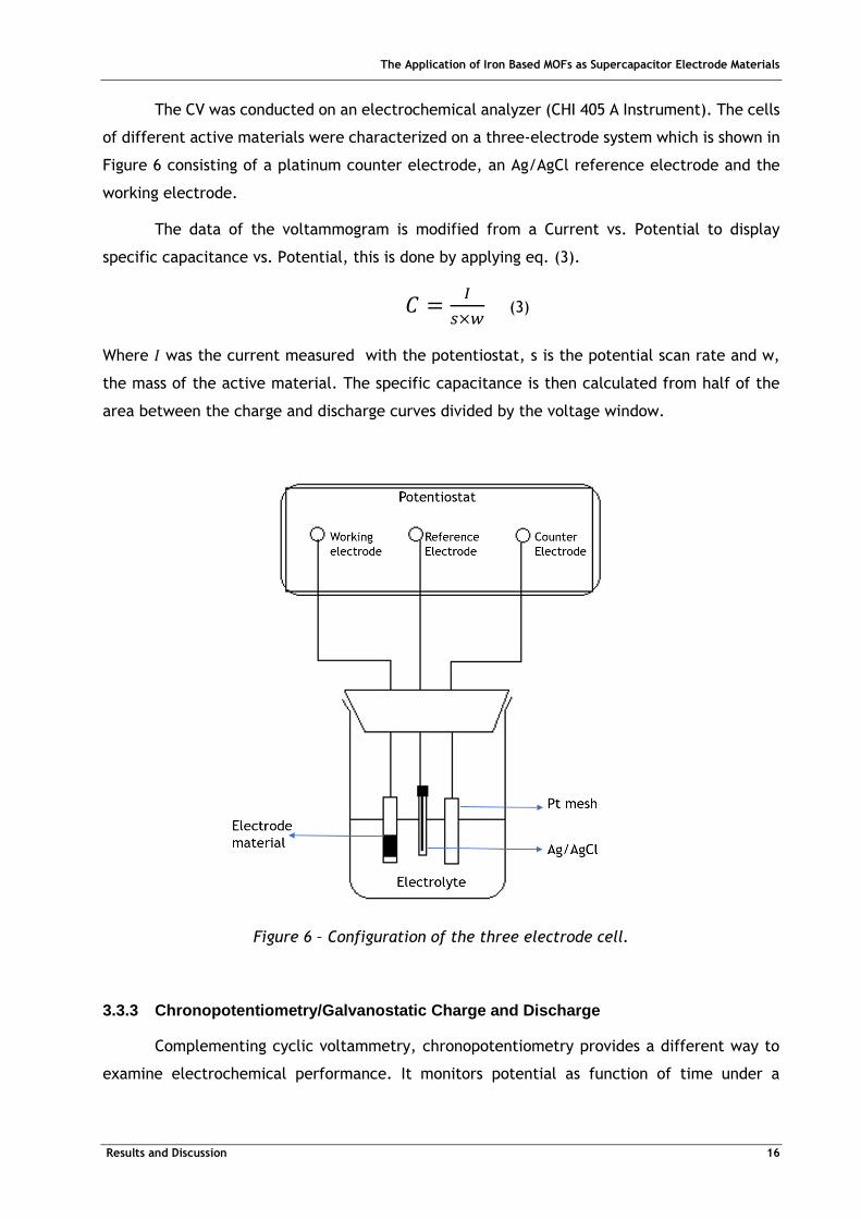
The CV was conducted on an electrochemical analyzer (CHI 405 A Instrument). The cells
of different active materials were characterized on a three-electrode system which is shown in
Figure 6 consisting of a platinum counter electrode, an Ag/AgCl reference electrode and the
working electrode.
The data of the voltammogram is modified from a Current vs. Potential to display
specific capacitance vs. Potential, this is done by applying eq. (3).
𝐶 =𝐼
𝑠×𝑤 (3)
Where I was the current measured with the potentiostat, s is the potential scan rate and w,
the mass of the active material. The specific capacitance is then calculated from half of the
area between the charge and discharge curves divided by the voltage window.
Figure 6 – Configuration of the three electrode cell.
3.3.3 Chronopotentiometry/Galvanostatic Charge and Discharge
Complementing cyclic voltammetry, chronopotentiometry provides a different way to
examine electrochemical performance. It monitors potential as function of time under a
The Application of Iron Based MOFs as Supercapacitor Electrode Materials
Results and Discussion 17
constant charge and discharge current. The setup was the same as the three electrode used in
CV measurement (Figure 6).
3.4 Surface Area and Pore Structure Analysis
The BET (Brunauer, Emmet and Teller) surface area and pore-size distribution of the
materials was determined by nitrogen adsorption with a surface area analyzer
(ASAP-2010/Micrometrics). BET method involves multi-layer adsorption of which the equation
is described as:
𝑃
𝑉(𝑃0−𝑃)=
1
𝑉𝑚𝑐+
(𝑐−1)
𝑉𝑚𝐶
𝑃
𝑃0 (4)
Where V is the volume of adsorbed nitrogen (cm3/g), P is the pressure of adsorbed gas, P0 is the
saturated vapor pressure, Vm is the volume of mono-layer adsorbed nitrogen and c is the BET
constant. The linear relation of P/V(P0-P)) and P/P0 can be obtained, which gives a slope of
(c-1)/Vmc and from this, the specific surface area can be calculated based on the volume of
adsorbed nitrogen [22]. BJH (Brunauere, Joyner and Halender) scheme for determination of
mesopore distribution is based on the Kelvin equation and thickness equation, showing the
relation between relative pressure and pore size. 8-points measurement was utilized for
determining BET surface area, in which the relative pressure ranging from 0.06 and 0.2. 55
points were measured for the characterizing mesopores. The interval time was set at 20
seconds.
3.5 Thermal Analysis
3.5.1 Thermogravimetric analysis
Thermogravimetric analysis (TGA) was performed using a PerkinElmer Diamond TGA-DTA
thermal analyser. TGA can monitor the mass of samples while heated at a constant rate. The
heating of the sample can be performed with different gases and for these tests nitrogen gas
was used.
TGA thermal curves will display the mass percentage of the sample vs. temperature.
The Application of Iron Based MOFs as Supercapacitor Electrode Materials
Results and Discussion 18
4 Results and discussion
In this chapter each material is characterized one by one, first by presenting the results of
characterization tests followed by electrochemical tests.
4.1 Characterization of ZIF-8
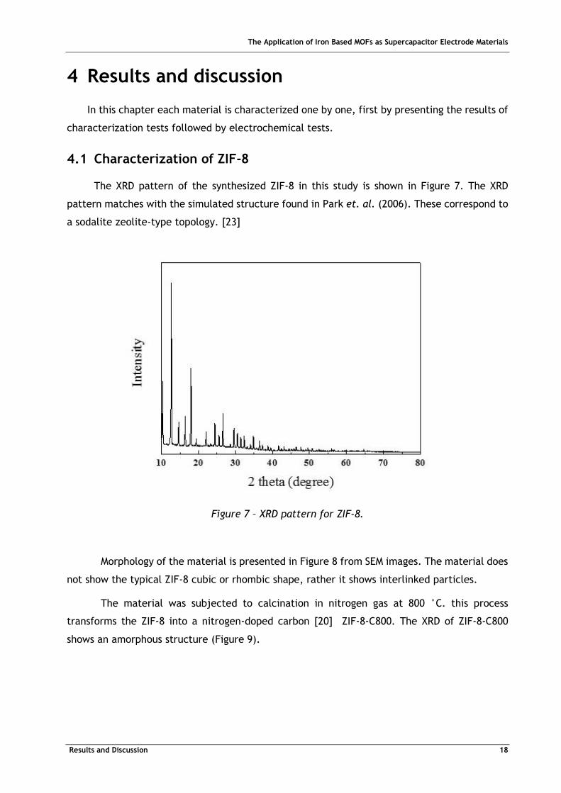
The XRD pattern of the synthesized ZIF-8 in this study is shown in Figure 7. The XRD
pattern matches with the simulated structure found in Park et. al. (2006). These correspond to
a sodalite zeolite-type topology. [23]
Figure 7 – XRD pattern for ZIF-8.
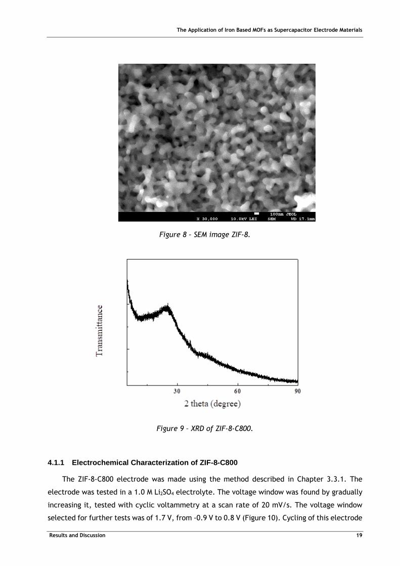
Morphology of the material is presented in Figure 8 from SEM images. The material does
not show the typical ZIF-8 cubic or rhombic shape, rather it shows interlinked particles.
The material was subjected to calcination in nitrogen gas at 800 °C. this process
transforms the ZIF-8 into a nitrogen-doped carbon [20] ZIF-8-C800. The XRD of ZIF-8-C800
shows an amorphous structure (Figure 9).
The Application of Iron Based MOFs as Supercapacitor Electrode Materials
Results and Discussion 19
Figure 8 – SEM image ZIF-8.
Figure 9 – XRD of ZIF-8-C800.
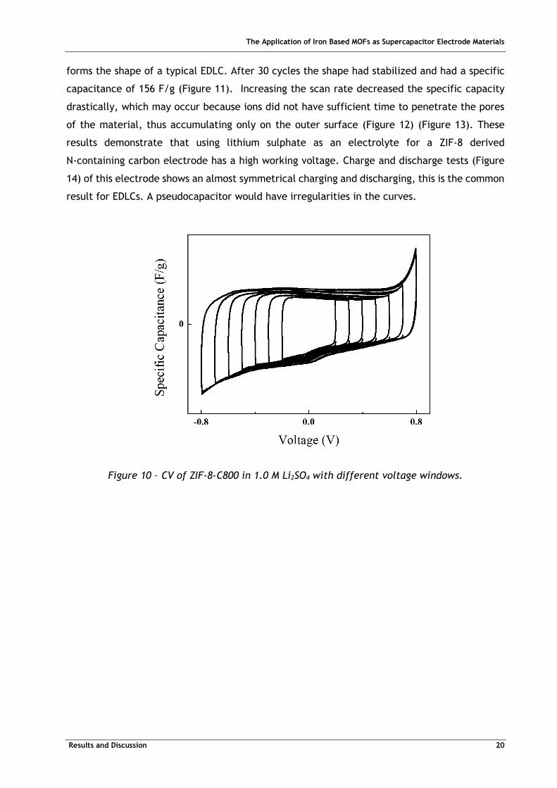
4.1.1 Electrochemical Characterization of ZIF-8-C800
The ZIF-8-C800 electrode was made using the method described in Chapter 3.3.1. The
electrode was tested in a 1.0 M Li2SO4 electrolyte. The voltage window was found by gradually
increasing it, tested with cyclic voltammetry at a scan rate of 20 mV/s. The voltage window
selected for further tests was of 1.7 V, from -0.9 V to 0.8 V (Figure 10). Cycling of this electrode
The Application of Iron Based MOFs as Supercapacitor Electrode Materials
Results and Discussion 20
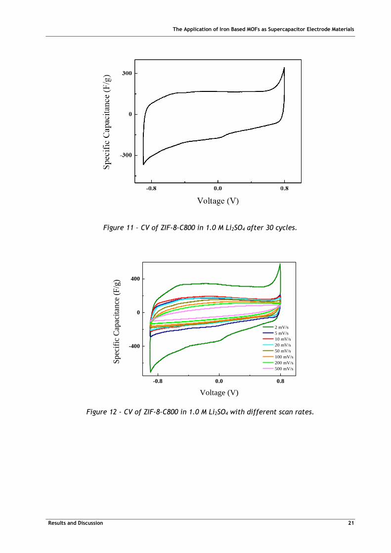
forms the shape of a typical EDLC. After 30 cycles the shape had stabilized and had a specific
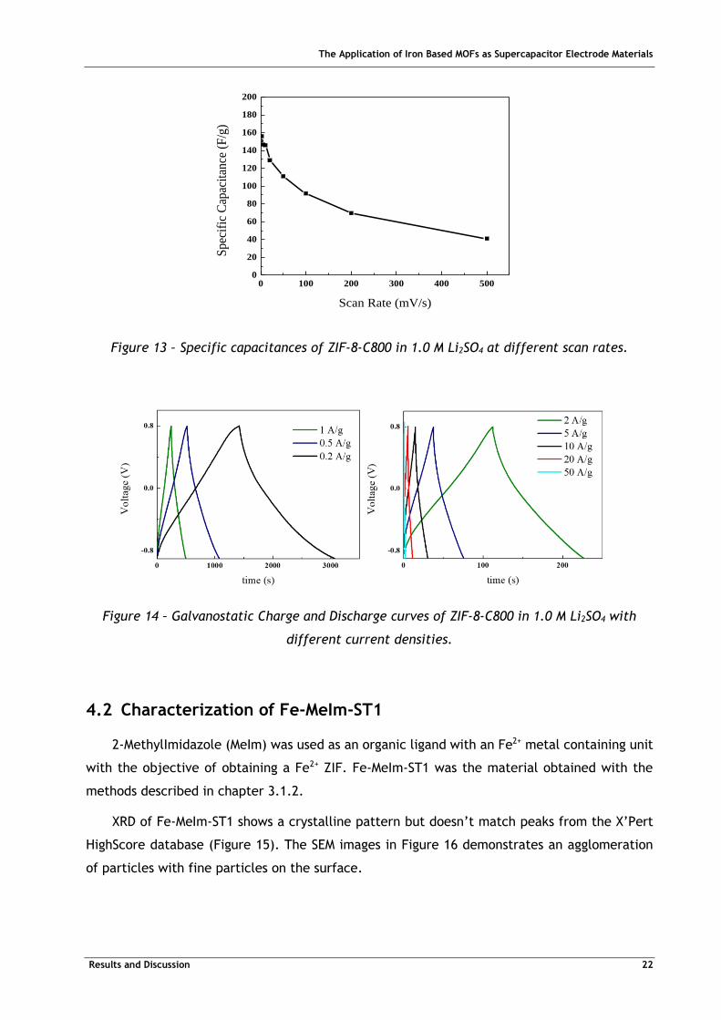
capacitance of 156 F/g (Figure 11). Increasing the scan rate decreased the specific capacity
drastically, which may occur because ions did not have sufficient time to penetrate the pores
of the material, thus accumulating only on the outer surface (Figure 12) (Figure 13). These
results demonstrate that using lithium sulphate as an electrolyte for a ZIF-8 derived
N-containing carbon electrode has a high working voltage. Charge and discharge tests (Figure
14) of this electrode shows an almost symmetrical charging and discharging, this is the common
result for EDLCs. A pseudocapacitor would have irregularities in the curves.
Figure 10 – CV of ZIF-8-C800 in 1.0 M Li2SO4 with different voltage windows.
The Application of Iron Based MOFs as Supercapacitor Electrode Materials
Results and Discussion 21
Figure 11 – CV of ZIF-8-C800 in 1.0 M Li2SO4 after 30 cycles.
-0.8 0.0 0.8
-400
0
400
Spec
ific
Cap
acit
ance
(F
/g)
Voltage (V)
2 mV/s
5 mV/s
10 mV/s
20 mV/s
50 mV/s
100 mV/s
200 mV/s
500 mV/s
Figure 12 - CV of ZIF-8-C800 in 1.0 M Li2SO4 with different scan rates.
The Application of Iron Based MOFs as Supercapacitor Electrode Materials
Results and Discussion 22
0 100 200 300 400 5000
20
40
60
80
100
120
140
160
180
200
Sp
ecif
ic C
apac
itan
ce (
F/g
)
Scan Rate (mV/s)
Figure 13 – Specific capacitances of ZIF-8-C800 in 1.0 M Li2SO4 at different scan rates.
Figure 14 – Galvanostatic Charge and Discharge curves of ZIF-8-C800 in 1.0 M Li2SO4 with
different current densities.
4.2 Characterization of Fe-MeIm-ST1
2-MethylImidazole (MeIm) was used as an organic ligand with an Fe2+ metal containing unit
with the objective of obtaining a Fe2+ ZIF. Fe-MeIm-ST1 was the material obtained with the
methods described in chapter 3.1.2.
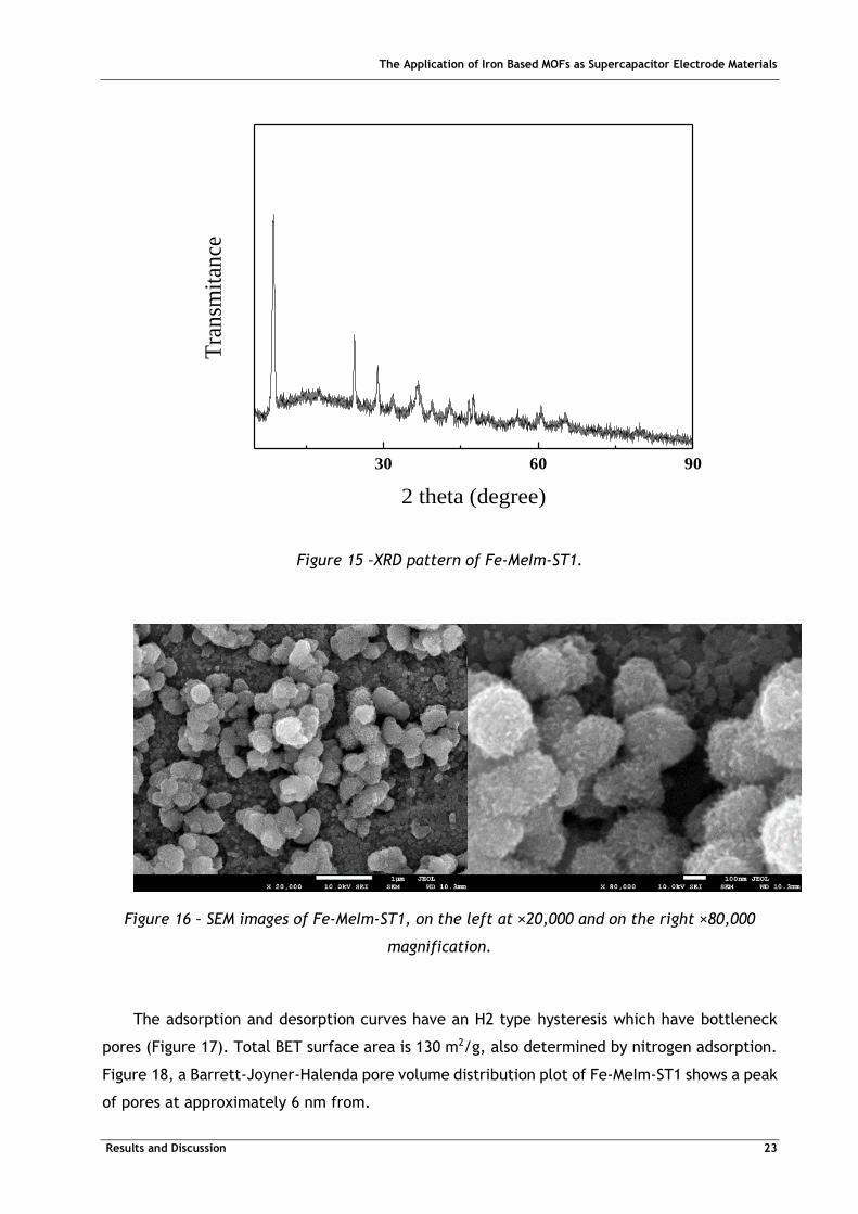
XRD of Fe-MeIm-ST1 shows a crystalline pattern but doesn’t match peaks from the X’Pert
HighScore database (Figure 15). The SEM images in Figure 16 demonstrates an agglomeration
of particles with fine particles on the surface.
The Application of Iron Based MOFs as Supercapacitor Electrode Materials
Results and Discussion 23
30 60 90
Tra
nsm
itan
ce
2 theta (degree)
Figure 15 –XRD pattern of Fe-MeIm-ST1.
Figure 16 – SEM images of Fe-MeIm-ST1, on the left at ×20,000 and on the right ×80,000
magnification.
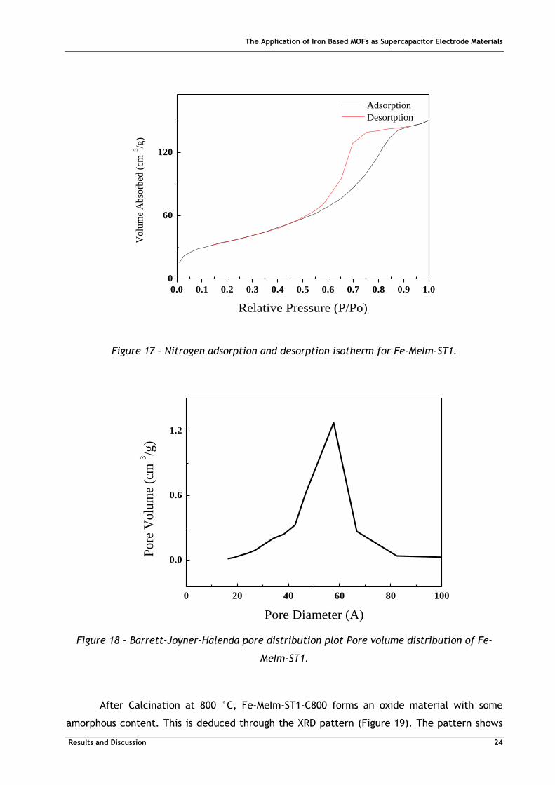
The adsorption and desorption curves have an H2 type hysteresis which have bottleneck
pores (Figure 17). Total BET surface area is 130 m2/g, also determined by nitrogen adsorption.
Figure 18, a Barrett-Joyner-Halenda pore volume distribution plot of Fe-MeIm-ST1 shows a peak
of pores at approximately 6 nm from.
The Application of Iron Based MOFs as Supercapacitor Electrode Materials
Results and Discussion 24
Figure 17 – Nitrogen adsorption and desorption isotherm for Fe-MeIm-ST1.
Figure 18 – Barrett-Joyner-Halenda pore distribution plot Pore volume distribution of Fe-
MeIm-ST1.
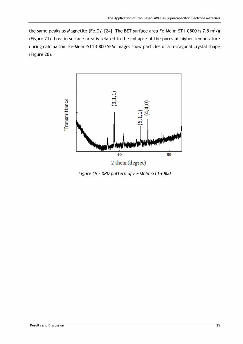
After Calcination at 800 °C, Fe-MeIm-ST1-C800 forms an oxide material with some
amorphous content. This is deduced through the XRD pattern (Figure 19). The pattern shows
0.0 0.1 0.2 0.3 0.4 0.5 0.6 0.7 0.8 0.9 1.0
0
60
120
Vo
lum
e A
bso
rbed
(cm
3/g
)
Relative Pressure (P/Po)
Adsorption
Desortption
0 20 40 60 80 100
0.0
0.6
1.2
Pore
Volu
me
(cm
3/g
)
Pore Diameter (A)
The Application of Iron Based MOFs as Supercapacitor Electrode Materials
Results and Discussion 25
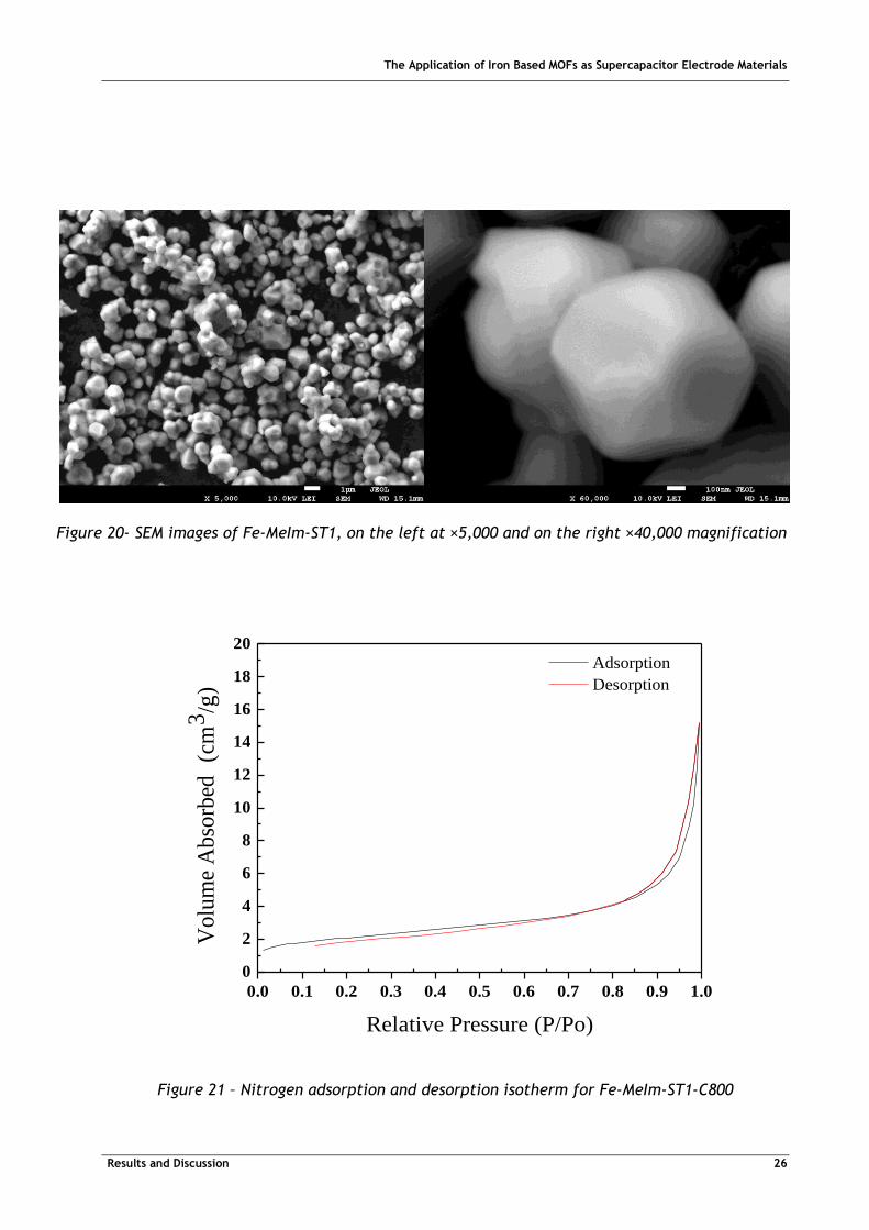
the same peaks as Magnetite (Fe3O4) [24]. The BET surface area Fe-MeIm-ST1-C800 is 7.5 m2/g
(Figure 21). Loss in surface area is related to the collapse of the pores at higher temperature
during calcination. Fe-MeIm-ST1-C800 SEM images show particles of a tetragonal crystal shape
(Figure 20).
Figure 19 - XRD pattern of Fe-MeIm-ST1-C800
The Application of Iron Based MOFs as Supercapacitor Electrode Materials
Results and Discussion 26
Figure 21 – Nitrogen adsorption and desorption isotherm for Fe-MeIm-ST1-C800
0.0 0.1 0.2 0.3 0.4 0.5 0.6 0.7 0.8 0.9 1.0
0
2
4
6
8
10
12
14
16
18
20
Volu
me
Abso
rbed
(c
m3
/g)
Relative Pressure (P/Po)
Adsorption
Desorption
Figure 20- SEM images of Fe-MeIm-ST1, on the left at ×5,000 and on the right ×40,000 magnification
The Application of Iron Based MOFs as Supercapacitor Electrode Materials
Results and Discussion 27
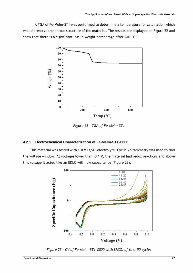
A TGA of Fe-MeIm-ST1 was performed to determine a temperature for calcination which
would preserve the porous structure of the material. The results are displayed on Figure 22 and
show that there is a significant loss in weight percentage after 240 °C.
200 400 6000
10
20
30
40
50
60
70
80
90
100W
eight
(%)
Temp.(°C)
Figure 22 – TGA of Fe-MeIm-ST1
4.2.1 Electrochemical Characterization of Fe-MeIm-ST1-C800
This material was tested with 1.0 M Li2SO4 electrolyte. Cyclic Voltammetry was used to find
the voltage window. At voltages lower than -0.1 V, the material had redox reactions and above
this voltage it acted like an EDLC with low capacitance (Figure 23).
Figure 23 – CV of Fe-MeIm-ST1-C800 with Li2SO4 of first 50 cycles

The Application of Iron Based MOFs as Supercapacitor Electrode Materials
Results and Discussion 28
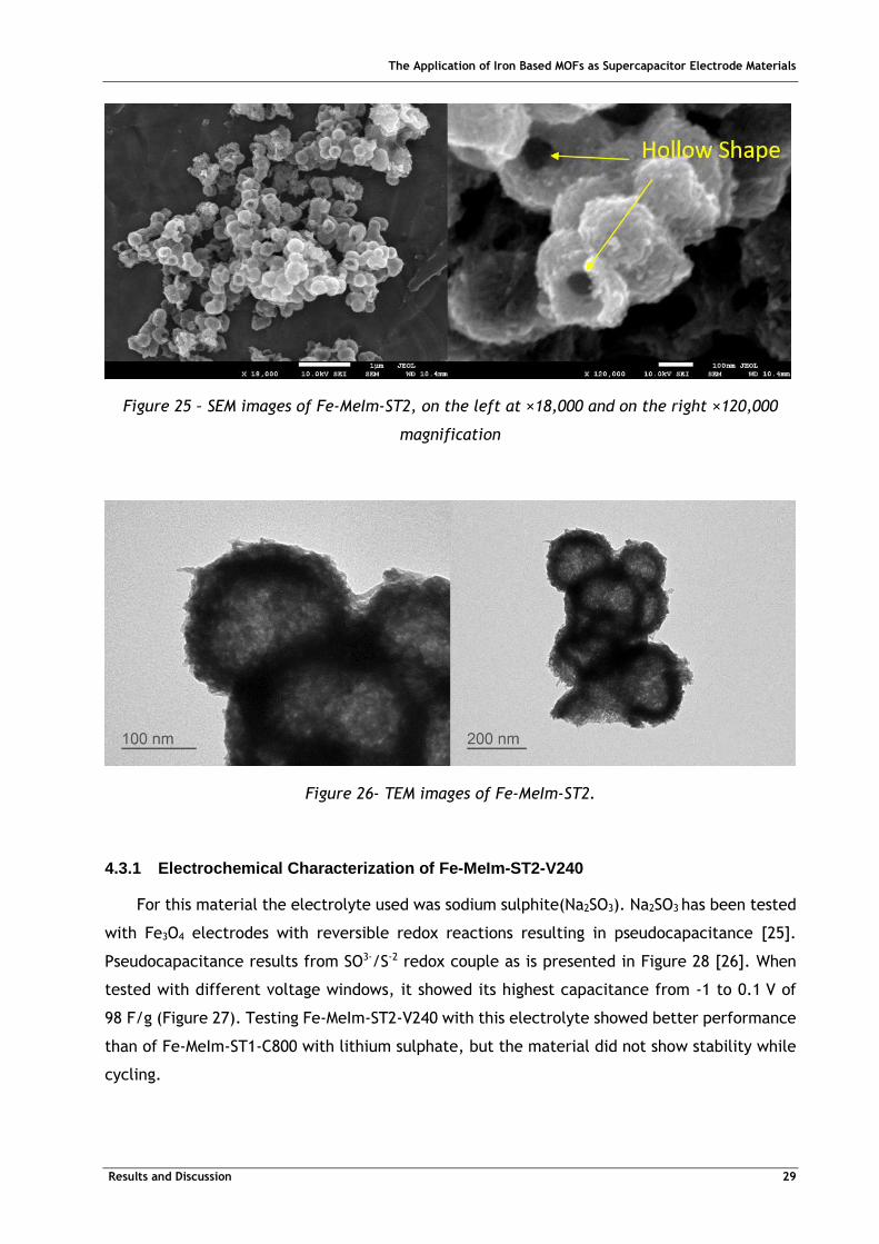
4.3 Characterization of Fe-MeIm-ST2
Although not as pronounced as in Fe-MeIm-ST1, the XRD pattern for Fe-MeIm-ST2
(Figure 24) presents the same peaks as those seen for the previous material (Figure 15). The
SEM images in Figure 25 show that the material forms hollow particles which could increase the
amount of surface area accessible to the electrolyte. Through EDX we know that the material
on the surface has a composition on the surface of 56% carbon, 32% oxygen and 12% iron in
atomic percentage. TEM images in Figure 26 show that that the material is made from smaller
rod-like particles which have aggregated. TGA was not performed on this material, but since
the material presented a similar XRD pattern to Fe-MeIm-ST1, it is hypothesized that the TGA
curve of Fe-MeIm-ST2 would be similar to that of Fe-MeIm-ST1 (Figure 22). Fe-MeIm-ST2 was
calcinated under vacuum at 240 °C and 300 °C without visible changes in structure, forming
Fe-MeIm-ST2-V240 and Fe-MeIm-ST2-V300 respectively.
30 60
Tra
nsm
itta
nce
2 theta (degree)
Figure 24 – XRD pattern of Fe-MeIm-ST2
The Application of Iron Based MOFs as Supercapacitor Electrode Materials
Results and Discussion 29
Figure 25 – SEM images of Fe-MeIm-ST2, on the left at ×18,000 and on the right ×120,000
magnification
Figure 26- TEM images of Fe-MeIm-ST2.
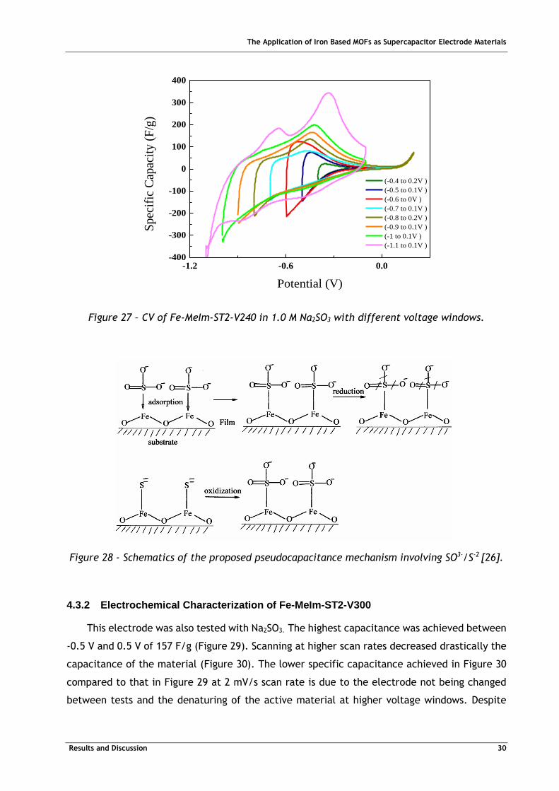
4.3.1 Electrochemical Characterization of Fe-MeIm-ST2-V240
For this material the electrolyte used was sodium sulphite(Na2SO3). Na2SO3 has been tested
with Fe3O4 electrodes with reversible redox reactions resulting in pseudocapacitance [25].
Pseudocapacitance results from SO3-/S-2 redox couple as is presented in Figure 28 [26]. When
tested with different voltage windows, it showed its highest capacitance from -1 to 0.1 V of
98 F/g (Figure 27). Testing Fe-MeIm-ST2-V240 with this electrolyte showed better performance
than of Fe-MeIm-ST1-C800 with lithium sulphate, but the material did not show stability while
cycling.
The Application of Iron Based MOFs as Supercapacitor Electrode Materials
Results and Discussion 30
-1.2 -0.6 0.0-400
-300
-200
-100
0
100
200
300
400
Sp
ecif
ic C
apac
ity
(F
/g)
Potential (V)
(-0.4 to 0.2V )
(-0.5 to 0.1V )
(-0.6 to 0V )
(-0.7 to 0.1V )
(-0.8 to 0.2V )
(-0.9 to 0.1V )
(-1 to 0.1V )
(-1.1 to 0.1V )
Figure 27 – CV of Fe-MeIm-ST2-V240 in 1.0 M Na2SO3 with different voltage windows.
Figure 28 - Schematics of the proposed pseudocapacitance mechanism involving SO3-/S-2 [26].
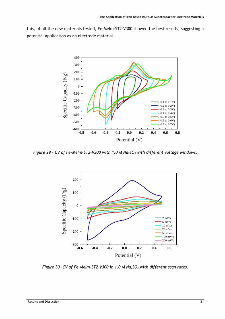
4.3.2 Electrochemical Characterization of Fe-MeIm-ST2-V300
This electrode was also tested with Na2SO3. The highest capacitance was achieved between
-0.5 V and 0.5 V of 157 F/g (Figure 29). Scanning at higher scan rates decreased drastically the
capacitance of the material (Figure 30). The lower specific capacitance achieved in Figure 30
compared to that in Figure 29 at 2 mV/s scan rate is due to the electrode not being changed
between tests and the denaturing of the active material at higher voltage windows. Despite
The Application of Iron Based MOFs as Supercapacitor Electrode Materials
Results and Discussion 31
this, of all the new materials tested, Fe-MeIm-ST2-V300 showed the best results, suggesting a
potential application as an electrode material.
-0.8 -0.6 -0.4 -0.2 0.0 0.2 0.4 0.6 0.8-600
-500
-400
-300
-200
-100
0
100
200
300
400
Spec
ific
Cap
acit
y (
F/g
)
Potential (V)
(-0.1 to 0.1V)
(-0.2 to 0.2V)
(-0.3 to 0.3V)
(-0.4 to 0.4V)
(-0.5 to 0.5V)
(-0.6 to 0.6V)
(-0.7 to 0.7V)
Figure 29 – CV of Fe-MeIm-ST2-V300 with 1.0 M Na2SO3 with different voltage windows.
Figure 30 -CV of Fe-MeIm-ST2-V300 in 1.0 M Na2SO3 with different scan rates.
-0.6 -0.4 -0.2 0.0 0.2 0.4 0.6-300
-200
-100
0
100
200
Sp
ecif
ic C
apac
ity
(F
/g)
Potential (V)
2 mV/s
5 mV/s
10 mV/s
20 mV/s
50 mV/s
100 mV/s
200 mV/s
The Application of Iron Based MOFs as Supercapacitor Electrode Materials
Results and Discussion 32
4.4 Characterization of Fe-Trz-ST1
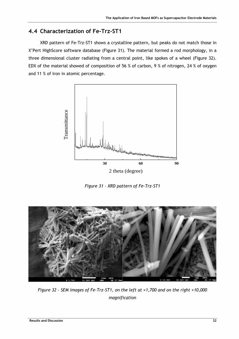
XRD pattern of Fe-Trz-ST1 shows a crystalline pattern, but peaks do not match those in
X’Pert HighScore software database (Figure 31). The material formed a rod morphology, in a
three dimensional cluster radiating from a central point, like spokes of a wheel (Figure 32).
EDX of the material showed of composition of 56 % of carbon, 9 % of nitrogen, 24 % of oxygen
and 11 % of Iron in atomic percentage.
Figure 31 - XRD pattern of Fe-Trz-ST1
Figure 32 - SEM images of Fe-Trz-ST1, on the left at ×1,700 and on the right ×10,000
magnification
30 60 90
Tra
nsm
itta
nce
2 theta (degree)
The Application of Iron Based MOFs as Supercapacitor Electrode Materials
Results and Discussion 33
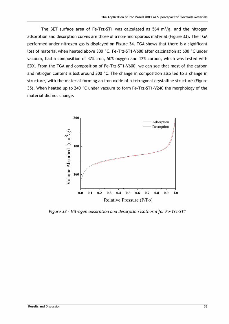
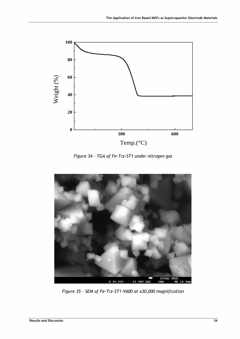
The BET surface area of Fe-Trz-ST1 was calculated as 564 m2/g. and the nitrogen
adsorption and desorption curves are those of a non-microporous material (Figure 33). The TGA
performed under nitrogen gas is displayed on Figure 34. TGA shows that there is a significant
loss of material when heated above 300 °C. Fe-Trz-ST1-V600 after calcination at 600 °C under
vacuum, had a composition of 37% iron, 50% oxygen and 12% carbon, which was tested with
EDX. From the TGA and composition of Fe-Trz-ST1-V600, we can see that most of the carbon
and nitrogen content is lost around 300 °C. The change in composition also led to a change in
structure, with the material forming an iron oxide of a tetragonal crystalline structure (Figure
35). When heated up to 240 °C under vacuum to form Fe-Trz-ST1-V240 the morphology of the
material did not change.
0.0 0.1 0.2 0.3 0.4 0.5 0.6 0.7 0.8 0.9 1.0
160
180
200
Volu
me
Abso
rbed
(c
m3
/g)
Relative Pressure (P/Po)
Adsorption
Desorption
Figure 33 – Nitrogen adsorption and desorption isotherm for Fe-Trz-ST1
The Application of Iron Based MOFs as Supercapacitor Electrode Materials
Results and Discussion 34
Figure 34 – TGA of Fe-Trz-ST1 under nitrogen gas
Figure 35 – SEM of Fe-Trz-ST1-V600 at x30,000 magnification
300 6000
20
40
60
80
100
Wei
ght
(%)
Temp.(°C)
The Application of Iron Based MOFs as Supercapacitor Electrode Materials
Results and Discussion 35
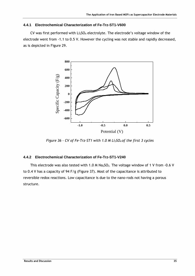
4.4.1 Electrochemical Characterization of Fe-Trz-ST1-V600
CV was first performed with Li2SO4 electrolyte. The electrode’s voltage window of the
electrode went from -1.1 to 0.5 V. However the cycling was not stable and rapidly decreased,
as is depicted in Figure 29.
-1.0 -0.5 0.0 0.5
-600
-400
-200
0
200
400
600
800
Sp
ecif
ic C
apac
ity
(F
/g)
Potential (V)
Figure 36 - CV of Fe-Trz-ST1 with 1.0 M Li2SO4 of the first 3 cycles
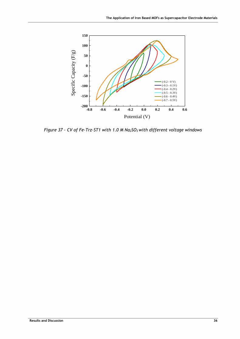
4.4.2 Electrochemical Characterization of Fe-Trz-ST1-V240
This electrode was also tested with 1.0 M Na2SO3. The voltage window of 1 V from -0.6 V
to 0.4 V has a capacity of 94 F/g (Figure 37). Most of the capacitance is attributed to
reversible redox reactions. Low capacitance is due to the nano-rods not having a porous
structure.
The Application of Iron Based MOFs as Supercapacitor Electrode Materials
Results and Discussion 36
-0.8 -0.6 -0.4 -0.2 0.0 0.2 0.4 0.6-200
-150
-100
-50
0
50
100
150
Spec
ific
Cap
acit
y (
F/g
)
Potential (V)
(-0.2 - 0 V)
(-0.3 - 0.1V)
(-0.4 - 0.2V)
(-0.5 - 0.3V)
(-0.6 - 0.4V)
(-0.7 - 0.5V)
Figure 37 - CV of Fe-Trz-ST1 with 1.0 M Na2SO3 with different voltage windows
The Application of Iron Based MOFs as Supercapacitor Electrode Materials
Results and Discussion 37
5 Conclusions and Future Perspectives
This project investigated the synthesis, characterization and performance of four
different materials for electrodes in supercapacitors. ZIF-8, Fe-MeIm-ST1, Fe-MeIm-ST2 and
Fe-Trz-ST1.
First, ZIF-8 was synthesized and tested to compare performance to that in literature.
Morphology of the synthesized ZIF-8 was different from those found in literature forming
interlinked, rather than separate particles. Nitrogen containing carbons derived from
ZIF-8-C800 had EDLC performance with a capacitance of 156 F/g and voltage window of 1.7 V
when tested with lithium sulphate electrolyte.
Synthesizing a ferrous ZIF was not possible, the result of this synthesis was an Iron oxide
material with carbon framework, Fe-MeIm-ST1. XRD showed a crystalline structure which was
not identified and was composed of an agglomeration of particles as seen in SEM images. After
calcination of the material at 800 °C, the electrode with Fe-MeIm-ST1-C800 as an active
material showed low capacitance with redox reactions at voltages lower than -0.1 V.
Changing the iron precursor from ferrous chloride to ferrous sulphate changed the
morphology of the material (Fe-MeIm-ST2), forming hollow particles, composed of aggregates
of smaller particles. After calcination of the material at 300 °C under vacuum,
Fe-MeIm-ST2-V300 showed better capacitance. This was achieved by using a 1.0 M sodium
sulphite electrolyte due to increased pseudocapacitance. Of the new materials synthesized
Fe-MeIm-ST2-V300 showed the best result.
Fe-Trz-ST1 nano-rods were synthesized from ferrous chloride and 1,2,4-Triazole. This
material did not have a microporous structure. Calcination above 300 °C led to the formation
of tetragonal iron oxide crystalline particles, similar to Fe-Trz-ST1-V600. Fe-Trz-ST1-V600 was
tested with a 1.0 M lithium sulphate electrolyte, which did not have stable cycling.
Fe-Trz-ST1-V240, kept the nano-rod morphology and when tested with 1.0 M sodium sulphite it
had a capacity of 94 F/g with a 1 V voltage window.
Future perspectives are to improve upon these MOFs. The next stage would be to
produce a ferrous ZIF, possibly by synthesizing it in an oxygen free environment and to see if
this enhances its performance as an electrode material. Further work needs to be carried out
to increase the stability of these new materials so that their structures are not affected by the
redox reactions. Testing these materials in different electrolytes may also improve their
performance.
In order to provide cheap and efficient energy storage devices to satisfy the demand,
new electrode materials need to be synthesized and carefully evaluated. They would need to

The Application of Iron Based MOFs as Supercapacitor Electrode Materials
Results and Discussion 38
combine high surface area, adequate pore-size and good electrical conductivity for better
supercapacitors.
The Application of Iron Based MOFs as Supercapacitor Electrode Materials
Results and Discussion 39
Bibliography
[1] A. González, E. Goikole, J. A. Barrena e R. Mysyk, “Review on supercapacitors:
Technologies and materials,” Renewable and Sustainable Energy Reviews, vol. 58, pp.
1189-1206, 2016.
[2] H. Chen, T. N. Cong, W. Yang, C. Tan, Y. Li e Y. Ding, “Progress in electrical energy
storage system: A critical review,” Progress in Natural Sciences, vol. 19, pp. 291-312,
2009.
[3] P. Simon, Y. Gogotsi e B. Dunn, “Where Do Batteries End and Supercapacitors Begin?,”
Science, vol. 343, pp. 1210-1211, 2014.
[4] P. S. John R. Miller, “Electrochemical capacitors for energy management,” Science, vol.
321, pp. 651-652, 2008.
[5] A. G. Pandolfo e A. F. Hollenkamp, “Carbon properties and their role in supercapacitors,”
Journal of Power Sources, vol. 157, p. 11–27, 2006.
[6] E. Frackowiaka e F. Béguinb, “Carbon materials for the electrochemical storage of energy
in capacitors,” Carbon, vol. 39, pp. 937-950, 2000.
[7] O. Yaghi e H. Li, “Hydrothermal Synthesis of a Metal-Organic Framework Containing Large
Rectangular Channels,” Journal of the American Chemistry Society, vol. 117, p. 10401–
10402, 1995.
[8] L. Wang, Y. Han, X. Feng e B. Wang, “Metal–organic frameworks for energy storage:
Batteries and supercapacitors,” Coordination Chemistry Reviews, vol. 307, pp. 361-381,
2016.
[9] H. Furukawa, K. E. Cordova, M. O’Keeffe e O. M. Yaghi, “The Chemistry and Applications
of Metal-Organic Frameworks,” Science, vol. 341, p. 974, 2013.
[10] X. Luo, J. Wang, M. Dooner e J. Clarke, “Overview of current development in electrical
energy storage technologies and the application potential in power system operation,”
Applied Energy, vol. 137, pp. 511-536, 2015.
[11] F. Lin, X. Dai, Z. Xu, J. Li e Z. Zhao, “High density capacitors,” High Power Laser and
Particle Beams, vol. 1, pp. 94-96, 2003.
The Application of Iron Based MOFs as Supercapacitor Electrode Materials
Results and Discussion 40
[12] R. Kötz e M. Carlen, “Principles and applications of electrochemical capacitors,”
Electrochimica Acta, vol. 45, pp. 2483-2498, 2000.
[13] P. Simon e Y. Gogotsi, “Materials for electrochemical capacitors,” Nature Materials, vol.
7, pp. 845-854, 2008.
[14] M. C. R Kotz, “Principles and applications of electrochemical capacitors,” Electrochim.,
Vols. %1 de %215-16, pp. 2483-2498, 2000.
[15] S. Kondrat, C. R. Pérez, V. Presser, Y. Gogotsi e A. Kornyshev, “Effect of pore size and its
dispersity on the energy storage in nanoporous,” Energy and Environmental Science, Vols.
%1 de %26474-6479, p. 5, 2012.
[16] M. A. Nasalevich, M. v. d. Veen, F. Kapteijn e J. Gascon, “Metal–organic frameworks as
heterogeneous photocatalysts: advantages and challenges,” CrystEngComm, vol. 16, pp.
4919-4926, 2014.
[17] L. Sun, C. H. Hendon, S. S. Park, Y. Tulchinsky, R. Wan, F. Wang, A. Walshbc e M. Dincă,
“Is iron unique in promoting electrical conductivity in MOFs?,” Chemical Science, vol. 6,
pp. 4450-4457, 2017.
[18] R. Banerjee, A. Phan, B. Wang, C. Knobler, H. Furukawa, M. O'Keeffe e O. M. Yaghi, “High-
throughput synthesis of zeolitic imidazolate frameworks and application to CO2 capture,”
Science, vol. 319, pp. 939-943, 2008.
[19] H.-L. Jiang, B. Liu, Y.-Q. Lan, K. Kuratani, T. Akita, H. Shioyama, F. Zong e Q. Xu, “From
metal-organic framework to nanoporous carbon: toward a very high surface area and
hydrogen uptake.,” Journal of the American Chemical Society, vol. 133, pp. 11854-11857,
2011.
[20] J. Tang, R. R. Salunkhe, J. Liu, N. L. Torad, M. Imura, S. Furukawa e Y. Yamauchi,
“Thermal Conversion of Core–Shell Metal–Organic Frameworks: A New Method for
Selectively Functionalized Nanoporous Hybrid Carbon,” Journal of the American Chemical
Society, vol. 137, pp. 1572-1580, 2015.
[21] Y. Pan, Y. Liu, G. Zeng, L. Zhao e Z. Lai, “Rapid synthesis of zeolitic imidazolate
framework-8 (ZIF-8) nanocrystals in an aqueous system,” Chem. Commun., vol. 47, pp.
2071-2073, 2011.
[22] S. Brunauer, P. H. Emmett e E. Teller, “Adsorption of Gases in Multimolecular Layers,”
Journal of the American Chemical Society, 1938.
The Application of Iron Based MOFs as Supercapacitor Electrode Materials
Results and Discussion 41
[23] K. S. Park, Z. Ni, A. P. Côté, J. Y. Choi, R. Huang, F. J. Uribe-Romo, H. K. Chae, M.
O’Keeffe e O. M. Yaghi, “Exceptional chemical and thermal stability of zeolitic
imidazolate frameworks.,” Proceedings of the National Academy of Sciences of the United
States of America, vol. 103, pp. 10186-10191, 2006.
[24] H. Okudera, K. Kihara e T. Matsumoto, “Temperature Dependence of Structure
Parameters in Natural Magnetite: Single Crystal X-Ray studies from 126 to 773 K,” Acta
Cryst., vol. B52, pp. 450-457, 1996.
[25] S.-Y. Wang, K.-C. Ho, S.-L. Kuo e N.-L. Wu, “Investigation on Capacitance Mechanisms of
Fe3O4 Electrochemical Capacitors,” Journal of the Electrochemical Society, vol. 163,
2006.
[26] N.-L. Wu e S.-Y. Wang, “Insight into Pseudocapacitance Mechanism for Fe3O4/Sulfite
Supercapacitor,” The Electrochemical Society.
[27] G. Wang, L. Zhang e J. Zhangb, “A review of electrode materials for electrochemical
supercapacitors,” vol. 41, pp. 797-828, 2012.