the antikythera mechanism and the early history of the moon-phase
TRANSCRIPT
319 MARCH 2006
AT the close of a recent article in this journal I drew attention to the probability that the more-or-less elaborate astronomical
displays of many early clocks may have drawn on a pre-existing tradition of astronomical dial-work. More specifically, I suggested the possibility that an unbroken tradition connected these early clock dials to the Antikythera Mechanism, dateable to the first century BC. In this instrument, the oldest surviving gear trains served the oldest surviving mechanized astronomical display.1
A common feature of the astronomical displays of early clocks, widely carried over as a feature of later conventional clock dials, is a display of the phases of the Moon. Often it is combined with a display of the age of the Moon in days. The events of the synodic month are, after all, among the more easily observed and commonly noticed astronomical phenomena, and in an earlier age without street-lighting a knowledge of the Moon’s phase was of practical use to anyone who thought of going out-of-doors at night. It is perhaps more surprising that the tradition survives even into our own time as a feature of many modern clocks and watches.
There exist two main ways of making such a display. In one, a disc rotates behind an aperture in a dial-plate, so that only a portion of it is seen at any time. The disc makes one turn in one, two or more synodic months. The design on the disc is so contrived that as it turns the visible portion gives an approximate representation of the waxing or waning Moon. In the other type, the Moon is represented by a globe of which only the front half is seen. The globe, half light and half dark, makes one full turn in each synodic month so as to reproduce the appearance of the waxing and waning Moon. Often the globe is
framed within an aperture, with its axis in the plane of the plate.
The first type of display has the advantage of requiring an absolute minimum of mechanism for its execution, and the further advantage of being flat. The second type, however, can portray the Moon’s phase accurately but at the expense of slightly increased mechanical complication and of greater depth of the dial-work.
Where the motions of both Sun and Moon are displayed on the dial, the rotation of either type of display of the phase is easily derived as the difference between them; whether the indicators show the diurnal motions of the bodies or their places in the Zodiac, that difference is still one revolution per synodic month. For the rotating-globe display, for example, the motion can in principle be transferred to the axis of the Moon globe simply by using a pair of equal wheels.
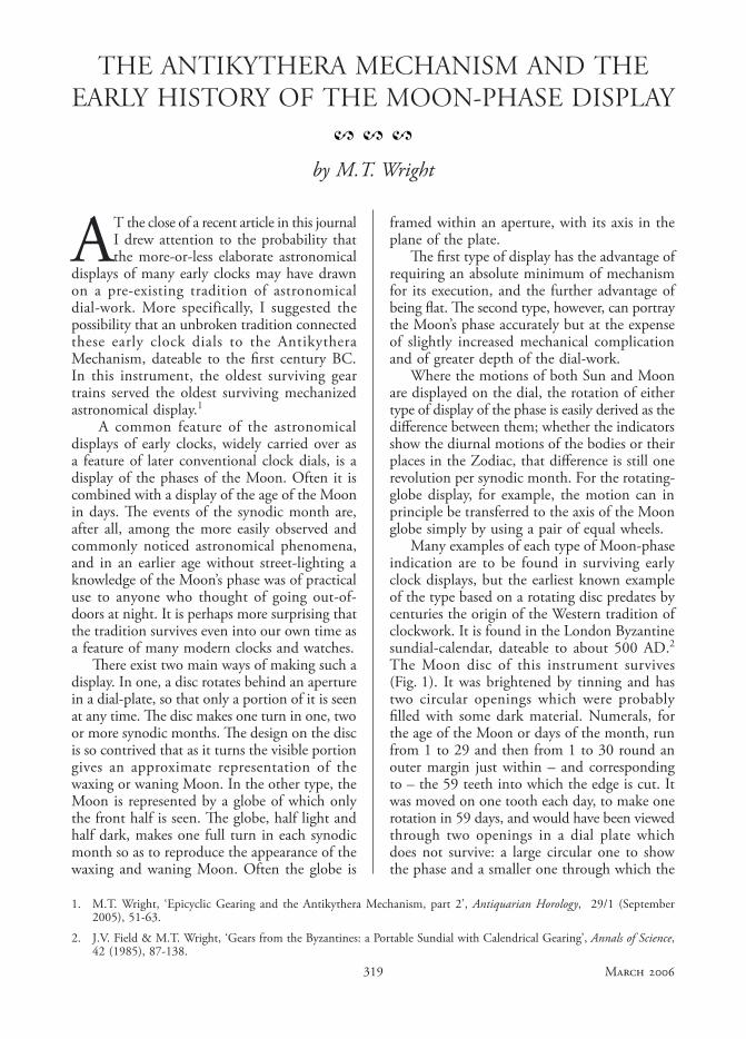
Many examples of each type of Moon-phase indication are to be found in surviving early clock displays, but the earliest known example of the type based on a rotating disc predates by centuries the origin of the Western tradition of clockwork. It is found in the London Byzantine sundial-calendar, dateable to about 500 AD.2 The Moon disc of this instrument survives (Fig. 1). It was brightened by tinning and has two circular openings which were probably filled with some dark material. Numerals, for the age of the Moon or days of the month, run from 1 to 29 and then from 1 to 30 round an outer margin just within – and corresponding to – the 59 teeth into which the edge is cut. It was moved on one tooth each day, to make one rotation in 59 days, and would have been viewed through two openings in a dial plate which does not survive: a large circular one to show the phase and a smaller one through which the
THE ANTIKYTHERA MECHANISM AND THE EARLY HISTORY OF THE MOON-PHASE DISPLAY
by M.T. Wright
1. M.T. Wright, ‘Epicyclic Gearing and the Antikythera Mechanism, part 2’, Antiquarian Horology, 29/1 (September 2005), 51-63.
2. J.V. Field & M.T. Wright, ‘Gears from the Byzantines: a Portable Sundial with Calendrical Gearing’, Annals of Science, 42 (1985), 87-138.
2 2 2
320ANTIQUARIAN HOROLOGY
Fig. 1. Moon-phase disc, Byzantine sundial-calendar, Science Museum, London, inv. no.1983-1393.
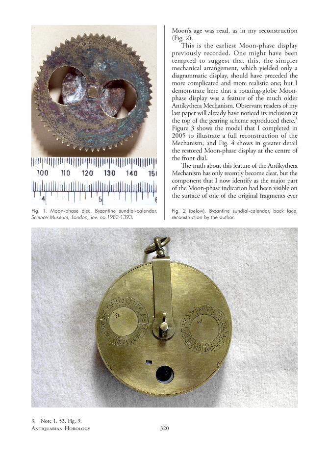
Fig. 2 (below). Byzantine sundial-calendar, back face, reconstruction by the author.
Moon’s age was read, as in my reconstruction (Fig. 2).
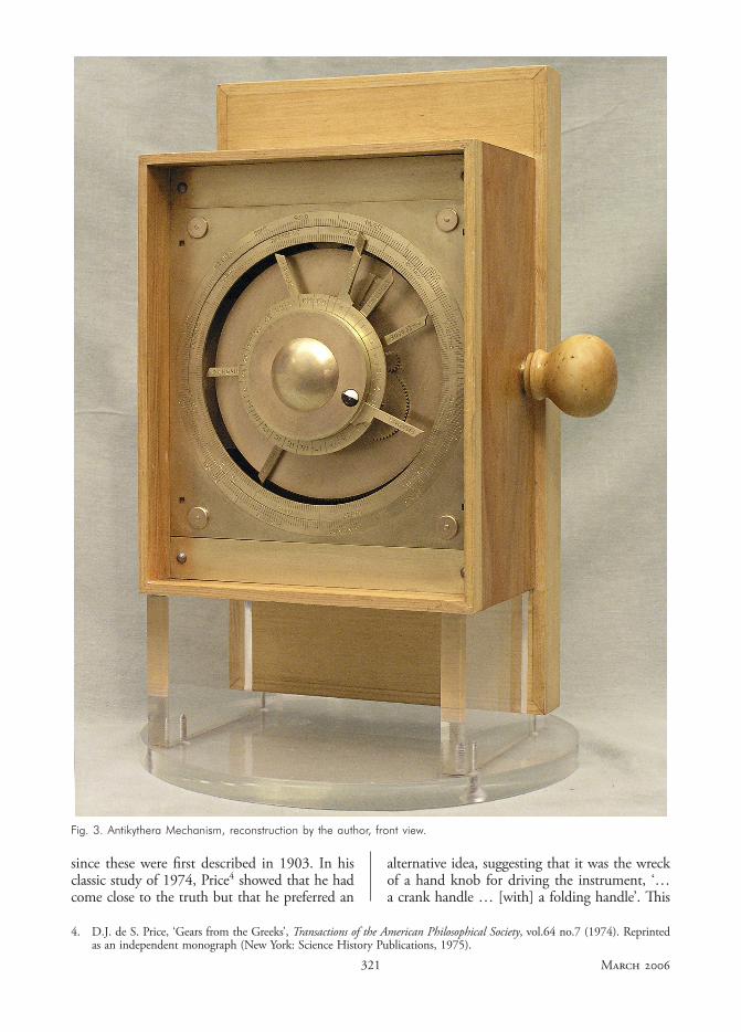
This is the earliest Moon-phase display previously recorded. One might have been tempted to suggest that this, the simpler mechanical arrangement, which yielded only a diagrammatic display, should have preceded the more complicated and more realistic one; but I demonstrate here that a rotating-globe Moon-phase display was a feature of the much older Antikythera Mechanism. Observant readers of my last paper will already have noticed its inclusion at the top of the gearing scheme reproduced there.3 Figure 3 shows the model that I completed in 2005 to illustrate a full reconstruction of the Mechanism, and Fig. 4 shows in greater detail the restored Moon-phase display at the centre of the front dial.
The truth about this feature of the Antikythera Mechanism has only recently become clear, but the component that I now identify as the major part of the Moon-phase indication had been visible on the surface of one of the original fragments ever
3. Note 1, 53, Fig. 9.
321 MARCH 2006
Fig. 3. Antikythera Mechanism, reconstruction by the author, front view.
4. D.J. de S. Price, ‘Gears from the Greeks’, Transactions of the American Philosophical Society, vol.64 no.7 (1974). Reprinted as an independent monograph (New York: Science History Publications, 1975).
since these were first described in 1903. In his classic study of 1974, Price4 showed that he had come close to the truth but that he preferred an
alternative idea, suggesting that it was the wreck of a hand knob for driving the instrument, ‘… a crank handle … [with] a folding handle’. This
322ANTIQUARIAN HOROLOGY
interpretation was palpably wrong, and yet it has been followed by most subsequent writers on the Mechanism.
THE EVIDENCE OF THE ORIGINAL FRAGMENTS
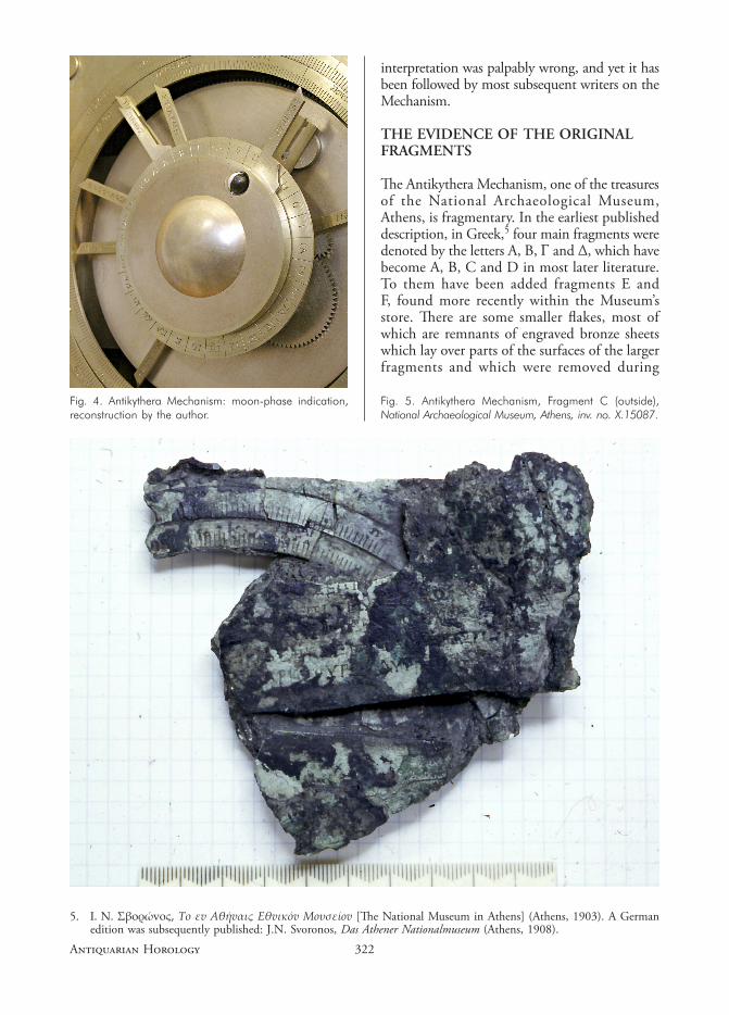
The Antikythera Mechanism, one of the treasures of the National Archaeological Museum, Athens, is fragmentary. In the earliest published description, in Greek,5 four main fragments were denoted by the letters A, B, Γ and ∆, which have become A, B, C and D in most later literature. To them have been added fragments E and F, found more recently within the Museum’s store. There are some smaller flakes, most of which are remnants of engraved bronze sheets which lay over parts of the surfaces of the larger fragments and which were removed during
Fig. 5. Antikythera Mechanism, Fragment C (outside), National Archaeological Museum, Athens, inv. no. X.15087.
Fig. 4. Antikythera Mechanism: moon-phase indication, reconstruction by the author.
5. I. N. Σβoρώvoς, Το εv Αθήvαις Εθvικόv Μoυσείov [The National Museum in Athens] (Athens, 1903). A German edition was subsequently published: J.N. Svoronos, Das Athener Nationalmuseum (Athens, 1908).

323 MARCH 2006
cleaning and conservation. Some of these have been re-joined to make a more extensive piece now called fragment G, while the remainder are individually distinguished by numbers. Here, however, we are concerned only with fragments A, B, C and – in passing – E.
The basis of my restoration of the Moon-phase display is a component found within original fragment C (Figs 5 & 6). Nearly all the surviving mechanical detail lies, however, within fragment A (Fig. 7). Fragments A, B and E have common fracture surfaces which may be fitted together, and together they constitute by far the greater part of the bulk of what survives. There is no such join for fragment C, and so we have to consider the possibility that it might have formed part of a different instrument. Nevertheless fragment C matches the others in style, workmanship and condition, so there is no clear reason to reject it; and it is readily incorporated in a convincing reconstruction. The largest single element within it is the corner of a dial plate, which Price and I agree in restoring as the front face of the instrument.
Fig. 7. Antikythera Mechanism, Fragment A (front). Note that this image is reproduced at a smaller scale than those of Figs 5 & 6. National Archaeological Museum, Athens, inv. no. X.15087.
Fig. 6. Antikythera Mechanism, Fragment C (inside), National Archaeological Museum, Athens, inv. no. X.15087.
324ANTIQUARIAN HOROLOGY
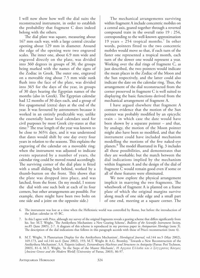
I will now show how well the dial suits the reconstructed instrument, in order to establish the probability that fragment C does indeed belong with the others.
The dial plate was square, measuring about 167 mm each way, with a large central circular opening about 129 mm in diameter. Around the edge of the opening were two engraved scales. The inner one, about 6.9 mm wide and engraved directly on the plate, was divided into 360 degrees in groups of 30, the groups being marked with the names of the signs of the Zodiac in Greek. The outer one, engraved on a moveable ring about 7.5 mm wide sunk flush into the face of the plate, was divided into 365 for the days of the year, in groups of 30 days bearing the Egyptian names of the months (also in Greek). The Egyptian calendar had 12 months of 30 days each, and a group of five epagomenal (extra) days at the end of the year. It was favoured by astronomers because it worked in an entirely predictable way, unlike the essentially lunar local calendars used for civil purposes by most Greek city-states at that time.6 The true length of the year was known to be close to 365¼ days, and it was understood that dates would shift by one day every four years in relation to the seasons. This explains the engraving of the calendar on a moveable ring: when the instrument was adjusted to indicate events separated by a number of years, the calendar ring could be moved round accordingly. The surviving corner of the dial plate is fitted with a small sliding bolt behind, worked by a thumb-button on the front. This shows that the plate was dropped into place, and was latched, from the front. (In my model, I restore the dial with one such bolt at each of its four corners, but other arrangements are possible. For example, there might have been two bolts on one side and a joint on the opposite side.)
The mechanical arrangements surviving within fragment A include concentric mobiles on a central axis, geared together through a reverted compound train in the overall ratio 19 : 254, corresponding to the well-known approximation 19 years = 254 tropical months.7 In other words, pointers fitted to the two concentric mobiles would move so that, if each turn of the faster one represented a tropical month, each turn of the slower one would represent a year. Working over the dial rings of fragment C, as just described, the two pointers would indicate the mean places in the Zodiac of the Moon and the Sun respectively, and the latter could also indicate the date on the calendar ring. Thus, the arrangement of the dial reconstructed from the corner preserved in fragment C is well suited to displaying the basic functions derived from the mechanical arrangement of fragment A.
I have argued elsewhere that fragment A contains evidence that the motion of the Sun pointer was probably modified by an epicyclic train – in which case the date would have been shown by a separate pointer – and that, by analogy, the motion of the Moon pointer might also have been so modified, and that the instrument could have included mechanism modelling the motions of the five naked-eye planets.8 The model illustrated in Fig. 3 includes all these possibilities, and demonstrates that they are workable; but the match between the dial indications implied by the mechanism within fragment A and the design of the dial of fragment C would remain good even if some or all of these features were eliminated.
We now explore the physical arrangement implicit in marrying the two fragments. The wheelwork of fragment A is planted on a frame plate of which the original margins survive along much of one side edge and a small part of one end, meeting at a square corner. The
6. The instrument was lost at a time when the Hellenistic world was controlled by Rome, but before the introduction of the Julian calendar in 45 BC.
7. In this I agree with Price, although my survey of the original fragments reveals a gearing scheme that differs significantly from his. See: M.T. Wright, ‘The Antikythera Mechanism: a New Gearing Scheme’, Bulletin of the Scientific Instrument Society, no.85 (June 2005), 2-7. A diagram of this scheme is reproduced in my previous paper in Antiquarian Horology (note 3). The description of the dial indications that follows in this paragraph accords with those of Price’s reconstruction (note 4).
8. M.T. Wright, ‘A Planetarium Display for the Antikythera Mechanism’, Horological Journal, vol.144 no.5 (May 2002), 169-173, and vol.144 no.6 (June 2002), 193; M.T. Wright & A.G. Bromley, ‘Towards a New Reconstruction of the Antikythera Mechanism’, S.A. Paipetis (editor), Extraordinary Machines and Structures in Antiquity (Patras: Peri Technon, 2003), 81-4; M.T. Wright, ‘In the Steps of the Master Mechanic’, Η Αρχαία Ελλάδα και ο Σύγχρονος Κόσµος [Ancient Greece and the Modern World] (University of Patras, 2003), 86-97.
325 MARCH 2006
plate appears originally to have been rectangular. Three arbors, two of them corresponding to the centres of dial systems on opposite faces of the instrument, are equidistant from the preserved side, which suggests that these arbors lay on the original midline of the plate and that a strip is lost from the broken side. A plausible mechanism for such a loss may be found. The strip would have been of about the width of the wooden batten, part of which still adheres to the back face of the frame plate along the preserved side. The plate could have broken along the line of the inner face of a corresponding batten, where it might well have become highly stressed as the instrument collapsed. On this assumption, the plate must have been about 158 mm wide.
Within fragment A there remain traces of further woodwork: one piece lying against the preserved side edge and another lying against the lower end of the plate.9 The two met at right-angles, at a mitred joint. This last detail compels us to interpret them as the remnants of a close-fitting rectangular case embracing the plate. The case probably extended to the front to enclose all the mechanism under the front dial. It is however clear that the back dial extended beyond this case, giving rise to the stepped form of case adopted in my reconstruction (Fig. 3).10
The battens on the back face of the frame plate may have served as spacers separating it from the back dial plate of the instrument. In my model they are fastened to the sides of the case so that they serve to secure the frame plate within the wooden case, into which it is inserted from behind. Details lying behind the frame plate are however irrelevant to our present discussion. What concerns us here is that the frame plate, together with the mechanism planted on it, was contained in a close-fitting case, and that the front dial was fitted independently to the front of the case. Comparison of the widths given above for the inside of the case (equal to the width of the frame plate) and of the dial plate suggests that the dial dropped into a rebate in the front of the case some 4.5 mm wide on each side. As may be seen in Fig. 3, the arrangement is workmanlike and visually satisfactory. In my
model I made the rebate deep enough to allow a flat plate (for which some evidence remains in the original) to be laid over the front without touching the hands.
Having no trace of a direct connection between fragments A and C, we may imagine the case being just as deep as is necessary to contain whatever mechanism we may restore between the two. In my model it is deep enough to contain three assemblies added conjecturally to provide indications of the places of the superior planets Mars, Jupiter and Saturn, because the model illustrates the possibility that the instrument might have been a planetarium. If, however, a less elaborate reconstruction which does not include such wheel-work (but one which, I argue, makes less sense) were preferred, the case need not be so deep. In any event it is clear that the destruction of the wooden case due to its long immersion, and perhaps also to its subsequent drying-out, could have resulted in the detachment of fragments A and C from one another leaving no detectable common fracture face, just as we find them now.
It should also be pointed out that the restoration of the Moon-phase display to the Antikythera Mechanism, the subject of this paper, is not affected by any argument as to whether or not the instrument did actually display planetary motions.
EVIDENCE FOR THE MOON-PHASE ASSEMBLY
The match between the mechanical arrangement of fragment A and the design of the dial in fragment C confirms what the circumstances of discovery and all appearances suggest: that fragment C formed part of the larger mechanism. We now consider the assembly within fragment C that forms the basis of my restoration of the Moon-phase display. This part lies against the back of the dial fragment (Fig. 6) and is cemented to it by corrosion products. Its present association with the dial fragment is enough to suggest that it might have been an element in the dial display, and that it slid into its present position when the instrument broke
9. The latter piece has largely disappeared although the trace of where it lay is clear. The wood itself is seen in an early photograph reproduced by Svoronos (note 5).
10. I have suggested that the unusual form of the case may result from the marriage of parts of two separate pre-existing instruments, and the argument will be carried further in another paper that is now in preparation: M.T. Wright, The Other Antikythera Mechanism.
326ANTIQUARIAN HOROLOGY
up. As we discuss the reconstruction of the Moon-phase display based on this component, we shall indeed see how well it suits both the dial and the mechanism of fragment A.
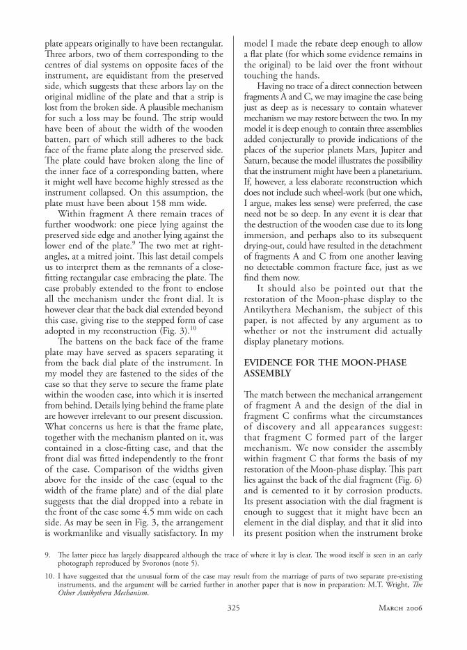
The assembly is based on a circular disc about 60 mm in diameter with a squared central hole of side about 2.7 mm The letter T is engraved close to, and aligned with, one side of the hole. The disc has a raised rim about 6.3 mm high around much of its edge. Some further features of interest are seen in Fig. 8, one of the sketches that I made on examining the original, when the function of the device was still unknown. The features are all arranged symmetrically about a radius to the disc, except that the square central hole – to the left – is not orientated to align with it. At the outer end – to the right – is a circular hole about 7.6 mm in diameter, which would have touched the inner face of the rim (broken away in this region). There is a well-defined hemispherical
11. The artefact is so far converted to corrosion-products that even in the thickest parts there seems to be little, if any, free metal remaining. Even though many components evidently retain their original forms, and even surface features such as scriber-marks, there is abundant evidence that the material is very brittle and friable.
12. M.T. Wright, A.G. Bromley & H. Magou, ‘Simple X-ray Tomography and the Antikythera Mechanism’, PACT 45 (1995), 531-543.
Fig. 8. Antikythera Mechanism: sketch of detail of Fragment C, from research notes, M.T. Wright.
depression in the mass of corrosion products beneath this hole. Towards the centre of the disc is a further, rectangular, hole in the disc, neatly filled by a component which projects through it although its upper part has crumbled away.11 Identification of this component, as described below, was crucial to the correct interpretation of the whole assembly. Between the two holes lie two raised cheeks about 2.5 mm apart, with a cross-pin fitted through them. A piece of bronze lies between the cheeks and projects above them, perhaps held in place by the pin.
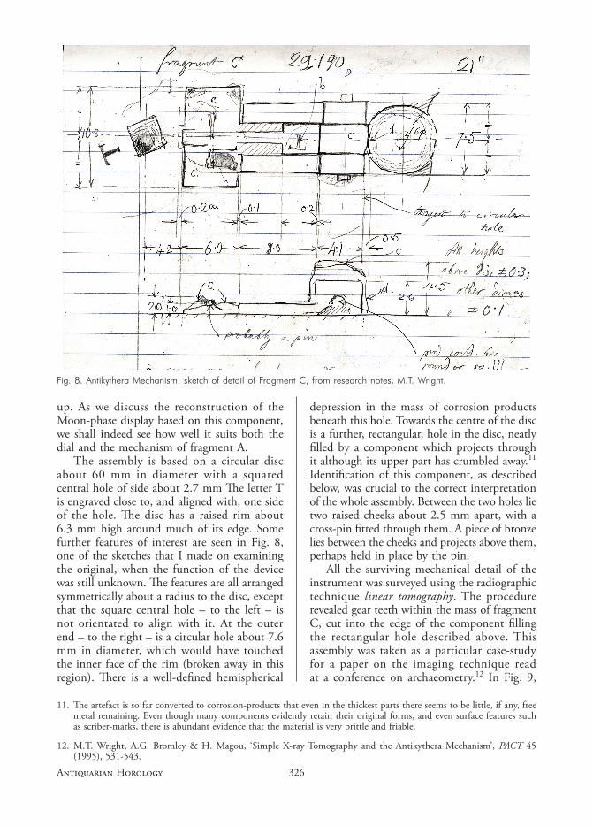
All the surviving mechanical detail of the instrument was surveyed using the radiographic technique linear tomography. The procedure revealed gear teeth within the mass of fragment C, cut into the edge of the component filling the rectangular hole described above. This assembly was taken as a particular case-study for a paper on the imaging technique read at a conference on archaeometry.12 In Fig. 9,
327 MARCH 2006
taken from that paper, I made no attempt to explain the mechanical arrangement but merely showed what seemed to be revealed. However, subsequent plain radiography of the fragment, with the disc lying edgeways within the pencil of rays and with the principal ray passing nearly along the radius of symmetry of the disc, showed that the toothed component has a partly-circular outline. Combining information from the different views, it became clear that the rectangular opening is occupied by the wreck of a small contrate wheel, of which the part that stood above the disc (as we now see it) is lost. This wheel lay with its axis in the plane of the disc and aligned to the radius of symmetry, with its teeth on the face further from the centre of the disc. Analysis of the images suggests that the wheel had about 24 teeth.
The small contrate wheel seems to have been fitted to an arbor which lay in a groove cut into the disc between the two cheeks. The arbor was held down by the cross-pin, possibly through a small block as intermediary. At the opposite end of the radial arbor, the smooth hemispherical depression in the corrosion products behind the circular hole suggests strongly that the hole was once filled by a small globe made of some material that did not corrode, which has since fallen out. With hindsight, the arrangement seems irresistibly suggestive of a rotating Moon-globe display, but the orientation of the wheel with its teeth outwards made it harder to see the maker’s intention. The solution to the puzzle became clear only when, recalling that the rotation of a Moon globe may be derived from the difference between the motions of Sun and Moon pointers by using a pair of equal wheels, the placing of the contrate wheel was analyzed with more care. Measurement showed that if
Fig. 9. Antikythera Mechanism: previous erroneous reconstruction of the detail of fragment C by the author.
it were turned round, so that its teeth faced toward the centre of the disc, its distance from the axis would be exactly such that it would run with a spur-wheel of an equal number of teeth on that central axis, correctly sized to engage the contrate wheel near to its outer edge.
It seems therefore that the Antikythera Mechanism suffered the indignity, depressingly common in the author’s experience as curator of a collection of mechanism, of having been taken apart and reassembled incorrectly. If, having put in the contrate wheel back-to-front, the mechanic were to have attempted to reassemble the instrument, the uncut shoulder of the contrate wheel would have borne firmly against the teeth of the spur wheel. The assembly would not have dropped into place, and if force had been applied damage would have ensued. It may be no mere accident of survival that the Moon-phase assembly is now found out of place, or that the spur wheel and the component that should have carried it are not found amongst the surviving fragments. We can only speculate as to the state of the instrument when it was lost.
RESTORATION OF THE MOON-PHASE DISPLAY
It will be recalled that one turn of the central arbor (in fragment A) represented one tropical month, and that one turn of the large wheel concentric with that arbor represented one year; and that – according to both Price and myself – indicators driven by them showed the places, respectively, of the Moon and of the Sun on the Zodiac scale of the dial (partially preserved in fragment C). In Price’s reconstruction the connection between internal mechanism and dial is straightforward and the indicators show the mean places of the Moon and Sun; whereas I suggest the possibility that these indications might have been modified by epicyclic mechanism interposed between the present fragment A and the dial, and the further possibility that indications of the places of some, or more probably all, of the planets might have been included on the dial. In any case the Moon-phase display reconstructed from the fragmentary assembly just described may be restored to this dial; the only requirement is that the Moon and Sun indicators must lie one immediately over the other.
328ANTIQUARIAN HOROLOGY
13. The small size of the squared hole at the centre of the disc precludes the possibility that it was mounted on a hollow arbor enclosing a smaller central one.
Whether the Moon indicator were simply fitted on to the extended end of the central arbor in fragment A or to a separate arbor connected to it (through an epicyclic assembly or other extra mechanism), it would still have been fitted to the central arbor projecting through the dial;13 and, even if separate, this is likely to have been of about the same diameter as the arbor below in fragment A: approximately 4.0 mm. The square hole at the centre of the disc, with its side of about 2.7 mm (and hence a diagonal measurement of about 3.8 mm), offers a convincing match. I conclude that the disc was mounted on the arbor that carried the indicator for the Moon’s place, and that the Moon-phase indication was carried round with this indicator, as was conventional in later dial-work.
The indicator for the Moon’s place was probably a finger fixed rigidly to the rim of the disc, extending along the radius through the Moon globe: again a conventional arrangement in later dial-work. We may imagine that when stress came upon the finger during the destruction of the instrument it was broken away along with a portion of the rim. I have modelled it, as I have all the other indicators, as an asymmetrical finger with a radial trailing edge. This design is based on the evidence of one fragmentary pointer that survives, embedded in corrosion products on the remaining portion of the upper back dial of the instrument.
We have established that the Moon-phase assembly rotated with the indicator for the Moon’s position. Therefore the spur wheel that engaged the contrate wheel to drive it must have turned with the indicator for the Sun’s position, and so this indicator must have lain directly under that for the Moon. The height of the rim on the Moon disc is such that, with a reasonable working clearance between the two indicators, a spur wheel mounted on the face of the Sun indicator lies in the right plane to engage the contrate wheel near its outer edge, and for the edge of the contrate wheel to clear the Sun indicator.
A horseshoe-shaped mark on the inner face of the Moon disc (Fig. 6) recalls the use elsewhere in the instrument of part-circular kerbs between mobiles and parts of the fixed frame, acting as spacers or serving to steady the mobiles on their arbors. I interpret the mark as showing the place where such a kerb was fixed to the Moon disc (perhaps by soft-soldering) in order to steady it against the Sun indicator and to ensure that the spur and contrate wheels remained correctly engaged. It may be significant that the centre of this part-circular trace falls exactly at the inner face of the contrate wheel where engagement with the spur wheel would have taken place. The spur wheel must therefore have been fixed to the face of a disc large enough for the kerb to have run against it, and the indicator for the
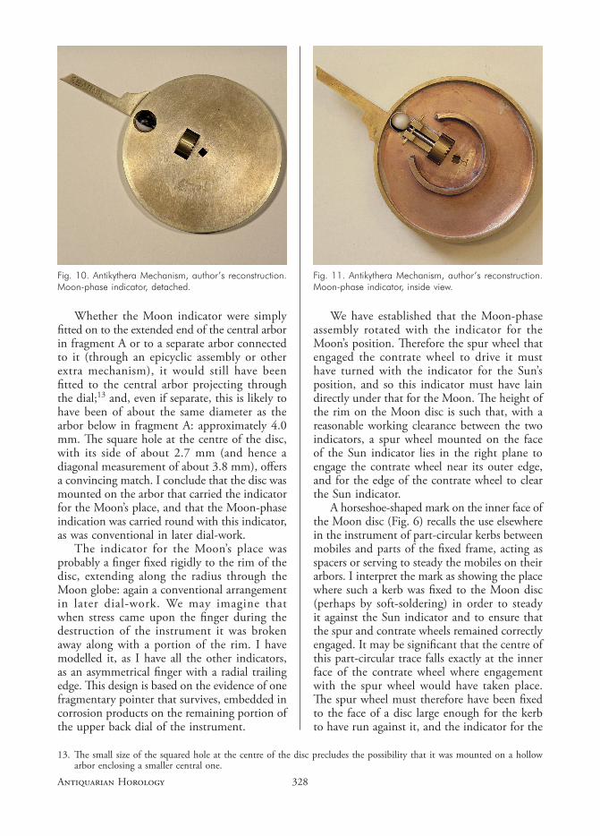
Fig. 10. Antikythera Mechanism, author’s reconstruction. Moon-phase indicator, detached.
Fig. 11. Antikythera Mechanism, author’s reconstruction. Moon-phase indicator, inside view.
329 MARCH 2006
Sun’s position would have been a radial finger extending from it.
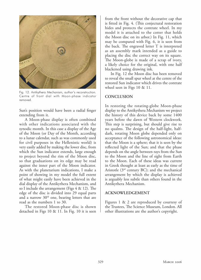
A Moon-phase display is often combined with other indications associated with the synodic month. In this case a display of the Age of the Moon (or Day of the Month, according to a lunar calendar, such as was commonly used for civil purposes in the Hellenistic world) is very easily added by making the lower disc, from which the Sun indicator extends, large enough to project beyond the rim of the Moon disc, so that graduations on its edge may be read against the inner part of the Moon indicator. As with the planetarium indications, I make a point of showing in my model the full extent of what might easily have been achieved in the dial display of the Antikythera Mechanism, and so I include the arrangement (Figs 4 & 12). The edge of the disc is divided into 29 equal parts and a narrow 30th one, bearing letters that are read as the numbers 1 to 30.
The restored Moon-phase disc is shown detached in Figs 10 & 11. In Fig. 10 it is seen
from the front without the decorative cap that is fitted in Fig. 4. (This conjectural restoration hides and protects the contrate wheel. In my model it is attached to the cotter that holds the Moon disc on its arbor.) In Fig. 11, which may be compared with Fig. 6, it is seen from the back. The engraved letter T is interpreted as an assembly mark intended as a guide to placing the disc the correct way on its square. The Moon-globe is made of a scrap of ivory, a likely choice for the original, with one half blackened using drawing ink.
In Fig. 12 the Moon disc has been removed to reveal the small spur wheel at the centre of the restored Sun indicator which drives the contrate wheel seen in Figs 10 & 11.
CONCLUSION
In restoring the rotating-globe Moon-phase display to the Antikythera Mechanism we project the history of this device back by some 1400 years before the dawn of Western clockwork. This step is surprising, but should give rise to no qualms. The design of the half-light, half-dark, rotating Moon globe depended only on acceptance of the following astronomical ideas: that the Moon is a sphere; that it is seen by the reflected light of the Sun; and that the phase depends on the angle between rays from the Sun to the Moon and the line of sight from Earth to the Moon. Each of these ideas was current in Greek thought at least as early as the time of Aristotle (3rd century BC); and the mechanical arrangement by which the display is achieved is arguably less subtle than others found in the Antikythera Mechanism.
ACKNOWLEDGEMENT
Figures 1 & 2 are reproduced by courtesy of the Trustees, The Science Museum, London. All other illustrations are the author’s copyright.
Fig. 12. Antikythera Mechanism, author’s reconstruction. Centre of front dial with Moon-phase indicator removed.