the 3dfm magnet drive amplifier
TRANSCRIPT

The 3DFM Magnet Drive Amplifier
UNCCH Department of Computer Science Technical Report TR05-002
Leandra Vicci, 10 January 2005

TR05-002 The 3DFM Magnet Drive Amplifier p2 of 11
Leandra Vicci UNCCH Department of Computer Science 1/10/2005
Summary The three dimensional force microscope (3DFM) is an instrument augmenting an optical microscope with the capability to apply forces to and measure the reaction of microscopic specimens in its optical field of view. The forces are applied to a microscopic magnetic bead by electromagnets. It is necessary to provide driving currents to the coils of these electromagnets proportional to a control signal, typically a voltage generated by a control computer. This report is a users’ guide and technical description of an amplifier designed for this purpose. This amplifier is a six channel transconductance amplifier, which means its output current is proportional to its input voltage. Its transconductance gain is 0.5 [A/V], meaning each Volt of input signal produces half an Ampere of output current. It was designed to drive a maximum of plus or minus 2.5 [Amperes] per channel into a 5 [mH] inductive load typical of the 3DFM drive coil operation. This requires an input signal range of -5 [V] to +5 [V]. For inductances significantly in excess of 50 [mH] , the circuits can be unstable and oscillate at high frequency with large amplitude. Operation of the amplifier outside these limits is possible, but its behavior may not be what you expect. The individual channels being transconductance amplifiers, operating them with their outputs shorted is acceptable, in which case the current in the short will be the same as for driving a coil. On the other hand, operating them open circuited, that is with no load connected, is an abnormal operating condition, and the output voltages can be expected to be nearly the maximum, either positive or negative. Nevertheless, this operating condition will not damage the amplifiers. What is not good for them is to make or break a connection to their loads while they are powered up. Operating procedures should be used to prevent this from happening, as it can initiate a large amplitude high frequency oscillation that may persist until the amplifier is powered down. This will probably not damage the amplifier, but may cause it to get quite hot; moreover it may also unduly heat the coils, and certainly is of no use in trying to control them in this condition.
Operation The amplifier input is connected by a cable from its DB-25 connector to a six channel signal source such as a DAC card of a computer. Each channel has a

TR05-002 The 3DFM Magnet Drive Amplifier p3 of 11
Leandra Vicci UNCCH Department of Computer Science 1/10/2005
signal and a reference wire, however the input signals are single-ended; that is, the reference wires are connected to the ground reference points of their respective amplifier boards, which are in turn connected to the amplifier’s internal ground. The amplifier output is connected by a cable from its DB-15 connector to the 3DFM coil assembly. Each channel has an output and a return wire, however the output signals are also single-ended; that is, the return wires are connected to the current-return points of their respective amplifier boards, which are in turn connected to the amplifier’s internal ground. The recommended I/O cabling is specified as,
Cable shielding should be connected to an appropriate ground at the far ends of the cables. No provision is made for connecting the shields at the amplifier. A standard power cord connection is provided by a Power Entry Module (PEM). In addition to the connector, the PEM contains a 6 [A] slow blow fuse, a power switch, and an AC power line noise filter. The fuse is behind a small red panel and can be accessed using a small screwdriver to pry open the panel. A fuse carrier plugs into the PEM behind the panel. While there is no pilot light, the PEM is in the on state when the “1” side of its Rocker switch is in, and off when the “0” side is in.

TR05-002 The 3DFM Magnet Drive Amplifier p4 of 11
Leandra Vicci UNCCH Department of Computer Science 1/10/2005
Frequency response The small signal frequency response of the amplifier is approximately 30 [kHz]. A Spice simulation of its transconductance transfer function when driving a typical load of 5 [mH] in series with 140 [mW] is shown here. Notice the low frequency gain of -6 [dB] represents the 0.5 [A/V] DC transconductance gain.
Provided that signal amplitudes are small enough to avoid slew rate limiting, the amplifier can be useful out to several tens of kiloHertz.
TR05-002 The 3DFM Magnet Drive Amplifier p5 of 11
Leandra Vicci UNCCH Department of Computer Science 1/10/2005
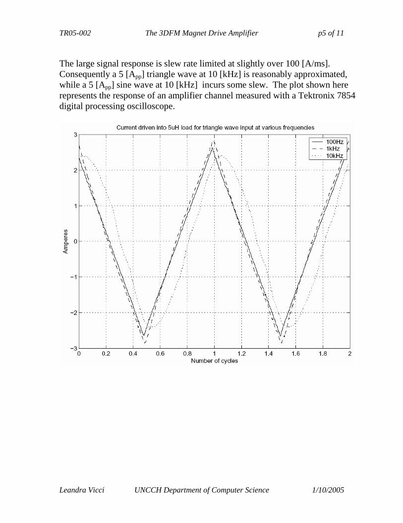
The large signal response is slew rate limited at slightly over 100 [A/ms]. Consequently a 5 [App] triangle wave at 10 [kHz] is reasonably approximated, while a 5 [App] sine wave at 10 [kHz] incurs some slew. The plot shown here represents the response of an amplifier channel measured with a Tektronix 7854 digital processing oscilloscope.

TR05-002 The 3DFM Magnet Drive Amplifier p6 of 11
Leandra Vicci UNCCH Department of Computer Science 1/10/2005
Appendix A: 3dfm User needs (Correspondence from R. Superfine)
Experiment Bead tracking
Force
range resolution bandwidth Slew rate
High Low Bandwidtha
Cilia Tracking1 10 µm 10nm 20 Hz 240µm/s 4.7nN? 10pN? 100 Hz Cell Mechanoresponse2
5 µm 25 µm/s 10pN 20 Hz
Bacterial Tracking3
50 µm 2 nm 1kHz 7µm/min 0.5µm/s
>2 nN
Kinetochore motion4
20 µm 2nm 1kHz >0.5nN
Molecular motors5 30 µm 2 nm 1kHz 1 µm/s 10pN Notes
a. Bandwidth for forces comes from two different kinds of experiments. One class of experiments is where we want to drive the system at a particular frequency or with a particular function (step, etc.) This would occur in the case where we are interested in, for example, measuring the viscosity of the environment by measuring the response of the bead to a driving force. The second class of experiment is a position clamp, where we seek to maintain a constant bead position by applying a time varying force that is responding to sample forces. The bandwidth for this latter experiment is presumably similar to that of the requirement for the bandwidth of the position measurement in the absence of force.
1. The slew rate in the cilia experiment is given by the maximum velocity of the cilium assuming a sinusoidal
path, where v=2πfA sin(2πf t) , taking A = about 2 µm and f = 20 Hz, we get 240 µm/s! The force generation is calculated from the number of outer dynein arms active potentially in generating a bend = (7 µm/24nm) *2*8pN= 4.7 nN! Holwill says that the viscous forces experienced by the cilia is 10pN. For bandwidth, we need to position clamp the cilia at different places in its motion. The cilia beats at about 15 Hz, and 100 Hz was taken as a comfortable bandwidth to produce clamp.
2. .Sanderson subjected cells to probe translation of 5 µm into cell surface in approx 0.2 sec. Low force is for stretching cilia, as we have seen. High force would be calculated from the elasticity of cells, which has been measured (Hoh, etc.)
3. Bacterial (Bead) tracking requirements are not all in one data set. The motion consists of molecular scale steps of about 5nm (~10msec for a single step) that result in an overall motion that is quite slow. The range of positional tracking is over the full width of a cell, while the resolution is the attempt to measure the individual steps that may be present in the motion, as has been claimed by Kuo. These need not be in a single data set. The force values are as expected by Theriot, although no data has been taken by anyone. The position clamp experiment should be very interesting here, with the low bandwidth being of immediate interest. The molecular scale steps are about 5.5 nm in about 10msec, giving a slew rate of 0.5µm/s for positional tracking, and a bandwidth of over 100 Hz for position clamp feedback using magnetic forces. The slow slew rate is for tracking the overall motion of the bacteria (bead). This experiment is expected to challenge the drift of the system, the position resolution and the high force capabilities
4. The range has been taken to be the size of the cell, while the resolution and bandwidth is assuming that single molecular events, as in cases 3 and 5, may occur and would be interesting to detect.
5. These are taken from Block paper on kinesin stepping. His system, as quoted, samples qpd signal at 2kHz, 12 bits, with an analog anti-alias filter at 1kHz. The slew rate is taken as the high end of average motion of bead as driven by motor. In another paper where he implemented a force clamp, he samples at 20kHz and filters at 10kHz, with a 12 bit ADC.

TR05-002 The 3DFM Magnet Drive Amplifier p7 of 11
Leandra Vicci UNCCH Department of Computer Science 1/10/2005
Appendix B: Overview of the design
Force on the bead is quadratically proportional to field strength, which below core saturation is nearly proportional to coil current. Except at very low frequencies, the coils behave inductively so it is necessary to directly control their currents rather than their voltages in order to provide a direct control of force. This requires transconductance coil drive amplifiers in which the output currents are linear functions of input voltages. The amplifiers must be DC coupled to provide long period steady forces. They must also provide sufficient bandwidth for studying the dynamics of biological samples. Unlike our previous DC prototype, we could find no off-the-shelf power amplifier ICs suitable for this purpose. We therefore designed a circuit to do the job. It provides excellent linearity over a current range of -2.5 to 2.5[A] at frequencies to several hundred Hertz. Full power bandwidth exceeds 5[A] peak-to-peak at 10[kHz], although linearity suffers at the higher frequencies. The output is taken from the collectors of a complementary pair of power Darlington transistors with current sensing for two feedback loops derived from their respective emitter terminals through sense resistors to their respective power supplies. This push-pull topology must be operated in class AB to provide linearity at crossover. Control of crossover current is an issue due to the thermal sensitivity of the power Darlingtons which may get very hot during operation. Accordingly, two overlapping feedback loops are used, one to linearize the transconductance response, and one to stabilize the crossover current. If these loops are allowed to interact, stability and transient effects are problematic. Interaction between these two loops is suppressed by operating the transconductance loop in common mode and the crossover feedback in differential mode. A bench prototype proved the concept, and a preproduction prototype circuit board was constructed, tested, and optimized (see photo). Its measured output for a 1[kHz] 5[App] triangle wave approximates the SPICE simulation of the circuit shown here
-6
-4
-2
0
2
4
6
0 s 200 us 400 us 600 us 800 us 1 ms
-2.5
-2
-1.5
-1
-0.5
0
0.5
1
1.5
2
2.5
3
Vol
tage
(V
)
Cur
rent
(A
)
Time
Transient response
v(in)
i(vout)
TR05-002 The 3DFM Magnet Drive Amplifier p8 of 11
Leandra Vicci UNCCH Department of Computer Science 1/10/2005
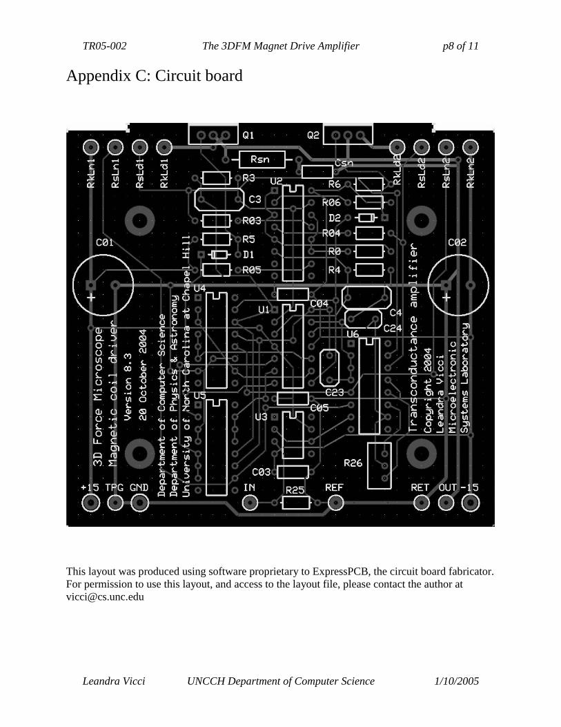
Appendix C: Circuit board
This layout was produced using software proprietary to ExpressPCB, the circuit board fabricator. For permission to use this layout, and access to the layout file, please contact the author at [email protected]

TR
05-002 T
he 3DF
M M
agnet Drive A
mplifier
p9 of 11
Leandra V
icci U
NC
CH
Departm
ent of Com
puter Science 1/10/2005
This schem
atic corresponds to the layout shown on the previous page
·!NO I 0 1
R25
PH" o---f
R26
12
•'Ut;·
J J
U4 ·
U4 '
, U4 ·
12
] 4
U4.
+ 15
PI
R5 R03 R05
I----GOUT
~RET
U4 15
R6
R2
- IS

TR05-002 The 3DFM Magnet Drive Amplifier p10 of 11
Leandra Vicci UNCCH Department of Computer Science 1/10/2005
Appendix D: Bill of materials Electronic parts R0 12k 0.1W 5% (MSL stock) R03 100 0.1W 1% (MSL stock) R04 100 0.1W 1% (MSL stock) R05 100 0.1W 1% (MSL stock) R06 100 0.1W 1% (MSL stock) R1 2.0 10W 1% Ohmite 810F2R0 Digikey 810F2R0-ND R2 2.0 10W 1% Ohmite 810F2R0 Digikey 810F2R0-ND R3 1k 0.1W 1% (MSL stock) R4 1k 0.1W 1% (MSL stock) R5 2k 0.1W 5% (MSL stock) R6 2k 0.1W 5% (MSL stock) R25 100k 0.1W 1% (MSL stock) R26 50 Ohm 10turn trimpot Bournes 3296W-1-500 Digikey 3296W-500-ND Rsn 24 2W 5% BC 5083NW24R00J12AFXBC Digikey BC24W-2CT-ND C01 100u 63V Aluminum Electrolytic (MSL stock) C02 100u 63V Aluminum Electrolytic (MSL stock) C03 0.1u 100V Monolithic Ceramic Panasonic ECU-S2A104KBA Digikey P4910-ND C04 0.1u 100V Monolithic Ceramic Panasonic ECU-S2A104KBA Digikey P4910-ND C05 0.1u 100V Monolithic Ceramic Panasonic ECU-S2A104KBA Digikey P4910-ND C3 22n 50V Polyropylene Panasonic ECQ-P1H223GZ Digikey P3223-ND C4 22n 50V Polyropylene Panasonic ECQ-P1H223GZ Digikey P3223-ND C23 1n 50V Polyropylene Panasonic ECQ-P1H102GZ Digikey P3102-ND C24 1n 50V Polyropylene Panasonic ECQ-P1H102GZ Digikey P3102-ND Csn 220n 50v Multilayer Ceramic Panasonic ECU-S1H224MEA Digikey P4966-ND D1 Small signal silicon Diode Fairchild 1N4148 Digikey 1N4148FS-ND D2 Small signal silicon Diode Fairchild 1N4148 Digikey 1N4148FS-ND Q1 PNP Darlington TO-220 pkg Fairchild TIP107 (MSL stock) Q2 NPN Darlington TO-220 pkg Fairchild TIP102 (MSL stock) U1 Quad precison high speed Op Amp TI TLE2144CN Digikey TLE2144CN U2 3NPN/2NPN Transistor Array Intersil CA3096AE Newark 06F2065 U3 Single JFET-input Op Amp TI TLE2071CP Digikey TLE2071CP U4 Octal 10k resistor array Vishay TDP1603 1002A (Mouser Electronics) U5 Octal 10k resistor array Vishay TDP1603 1002A (Mouser Electronics) U6 Octal 10k resistor array Vishay TDP1603 1002A (Mouser Electronics) Non-schematic and mechanical parts 6 Circuit board, Drive Amp v8.3 (ExpressPCB custom) (MSL design) 6 Heat sink cut from Wakefield 5052 (MSL stock) 1 8"x12"x2" aluminum chassis Hammond Mfg 1444-22 Digikey HM267-ND 1 Cover fabricated from 16Ga.3003-H14 perforated Al sheet McMaster-Carr 9232T151 2 15V 10A DC power supply Astrodyne MKS150-15 24 #2-56x0.25" SS pan head phillips machine screws (MSL stock) 84 #4-40x0.25" SS pan head phillips machine screws (MSL stock) 4 #4-40x0.375" SS pan head phillips machine screws (MSL stock) 10 #6-32x0.25" allen head cap screws (MSL stock) 10 #6 SS pan head phillips sheet metal screws MSC 87923082 8 M3x5mm SS pan head phillips machine screws MSC 68019165 10 #6-32 Nutserts Lawson 81084 Lawson on line at: http://webapp1.lawsonproducts.com/website/showItem?itemNum=81084 24 #4-40x0.5" threaded hex spacers Keystone 1450C Digikey 1450CK-ND 22 #4-40 SS hex nuts (MSL stock) 12 #4 fiber shoulder washers BiVar SW-031-145 (MSL stock) 12 TO-220 insulators Cho-Therm 1680 (MSL stock) 4 0.5"dia x 0.25" rubber foot McMaster-Carr 9540K11 (MSL stock) 4 #6 tubular solder lugs (MSL stock) Connectors 1 Female chassis mount DB15 connector, solder cup pins, #4-40 mounting hardware 1 Female chassis mount DB25 connector, solder cup pins, #4-40 mounting hardware 1 6A pwr entry mod w/sw,fuse&filt Corcom PS0S0SS60 Digikey CCM1600-ND 3 3/16" Quick-Disconnect terminals for #18AWG wire McMaster-Carr 7060K15 Wire * #18x3 teflon insulated stranded wire, color coded (MSL stock) * #22x2 teflon insulated stranded wire, color coded (MSL stock) Misc 1 6A/250V 3AB(314)series fuses Littlefuse 314006.H Digikey F160-ND

TR
05-002 T
he 3DF
M M
agnet Drive A
mplifier
p11 of 11
Leandra V
icci U
NC
CH
Departm
ent of Com
puter Science 1/10/2005
Appendix E
: Chassis layout
For detailed m
anufacturing drawings, please contact the author at vicci@
cs.unc.edu
~ ~ 1::!:!:!!1 !:!:!!:~ 1!:!!:1 ~
E!Jr::::Joc:::J "' E!Jr::::Joc:::J c:::J E!Jr::::Joc:::J c:::J
-j~oo A n ! oo~-[oo A n ! oo;;-oo A n ! oor--· u ~Do u ~Do u ~Do
!'~~0 0~ ~ .. o ~~~~ . .:;; =-[- ~~0 0~ Q. .. o ~~~~ . .:q =~ !'~o 0~. ~ . .o ~~~~.-'! ·--· i ! i ! i !
oi I 1 I OOOo I · I · i ! i ! i !
h:<'i"' r,. .. ~ ~0
='"fii __ ;,;.·i ,. ~·~ ~D =;ii __ .,..i,. ~·.§ ~D =~i o u D o ·-· o u D o ·-· o u D o "'-'
oDo ~ [ oDo ~ Doo ~ 0 i o ~ Oo 0 i o ~ Oo 0 i o ~ 0 oa ao- oa ao- oa ao
c:::~oCJ c:::JoCJ c:::JoCJ ~ CJI:m] G:;;:o] CJ~ t:::i<l CJ~
(!;;j"
=
~ = I
0
= 0~ 0
= ~
0 0 0 0 0 0
0 0 0 TIRE
MSL 3DFM Magnet Driver DESCRr?TtON
Above chassis oomponent layout
oRA.vm -sv Leandra Vied SIZE IDWGNO
OATE 28 Apr, 2003 A ISCAtE 1: 2.5 IREV 0 !SHeET 70F 7