the 3d click guide is a revolutionary adjustable surgical ... · nobel biocare, straumann...) as...
TRANSCRIPT

The 3D Click Guide is a revolutionary adjustable surgical guide for cases in which one-two implants are placed.
3D click Guide is an 'in-office' model-based surgical concept using data from bone sounding measurements or, if desired, CBCT. The 3D Click Guide kit is available in three sizes; narrow, regular, and wide diameter, allowing for fully guided implant placement in a wide range of clinical situations.
3D Click Guide system is compatible with the drill-guides available from major manufacturers (e.g. Nobel Biocare, Straumann...) as well as with our own low-cost universal drill guides.
Idondivi, Inc.
450 Sutter Street, suite 2530
San Francisco, CA 94108
US Toll-free: 1 (855) 3D CLICK
International: 1 (415) 362-2476
Email: [email protected]
Website: www.3dclickguide.com
Copyright © 2011 Idondivi Inc. All rights reserved. 3D Click Guide | Instructions for use | Page 01

The buccal wing (1st of 2 components making up the 'wing assembly'). Features, characteristics, and functions:
� Retention rail – 'click' connection to Rotation block.� Horizontal wings perforated for retention with ortho resin to the vacuform carrier (splint).� Cross bar with 'correction slot' into which the top of the BLP will fit.� Radiographic Implant Replica (RIR). Vertical segment characterized by 3 circular cut-outs (for radiographic distinction from the lingual RIR).� Designed and fabricated of materials demonstrating both radio opacity and PMMA ortho resin adhesion.� For close adaptation to the arch form of the vacuform carrier, the horizontal wings and RIR are designed to be deformed by hand. Use gentle adaptation forces only as abrupt bending can cause wing fracture.� This Buccal Wing component is available in 3 sizes Narrow (ND) Regular (RD), and Wide (WD).� Colors: ND = Green, RD = Yellow, WD = Red
B Buccal Wing
The lingual wing (2ND of 2 components making up the 'wing assembly'). Features, characteristics, and functions:
� Retention rail – 'click' connection to Rotation block.� Horizontal wings perforated for retention with ortho resin to the vacuform carrier (splint).� Radiographic Implant Replica (RIR). Vertical segment characterized by slot cut-out (for radiographic distinction from the buccal RIR).� Designed and fabricated of materials demonstrating both radio opacity and PMMA ortho resin adhesion.� For close adaptation to the arch form of the vacuform carrier, the horizontal wings and RIR are designed to be deformed by hand. Use gentle adaptation forces only as abrupt bending can cause wing fracture.� The lingual wing comes in 1 size only.� Color: White
C Lingual Wing
Rotation-blocks (set of 3); 0,3,7 degrees.
� The rotation blocks allow correction of the mesio-distal rotation when radiographically is determined that the laboratory selected trajectory needs modification.� A 3º or 7º degree correction can be selected. If no correction is needed and the initial setup was correct, then the 0 degree rotation-block is used.� Material is radio lucent.� The 3º and 7º degree rotation blocks have arrows indicating the direction towards the correction is made.� The rotation blocks come in sizes Narrow (ND), Regular (RD)and Wide diameter (WD).� Within each 3D Click Guide kit, 3 blocks are provided (0º ,3º, 7º)� Colors: 0º degree = Green 3º degree = Yellow 7º degree = Red
D Rotation-Blocks
� Once the bone sounding data are drawn onto the split cast, The Buccal Lingual Positioner (BLP), a measuring and positioning instrument, is placed and oriented against the split cast surface and affixed there by means of a pinhole fit and a drop of glue.� The BLP is designed with several distinct features in its outline form that allow for precise visual confirmation: pin (& lower groove) = top of the implant; 3 mm above is the 2nd groove for relating the implant top to the buccal gingival margin.� The top of the BLP fits into the correction slot of the buccal wing, allowing mesio distal corrections, while maintaining the established buccal lingual position.� The BLP is 4 mm wide; the length from the pin to the apex is 12 mm.� By design the BLP will position the top surface of the rotation-block 9 mm above the implant top, when the pinhole is drilled into the cast at the desired position corresponding to the implant top. The addition of 1 mm thickness of the drill guide creates the + 10 mm which should be added to the total drill length.� Color: Blue
A BLP
Copyright © 2011 Idondivi Inc. All rights reserved. 3D Click Guide | Instructions for use | Page 02
Copyright © 2011 Idondivi Inc. All rights reserved. 3D Click Guide | Instructions for use | Page 03
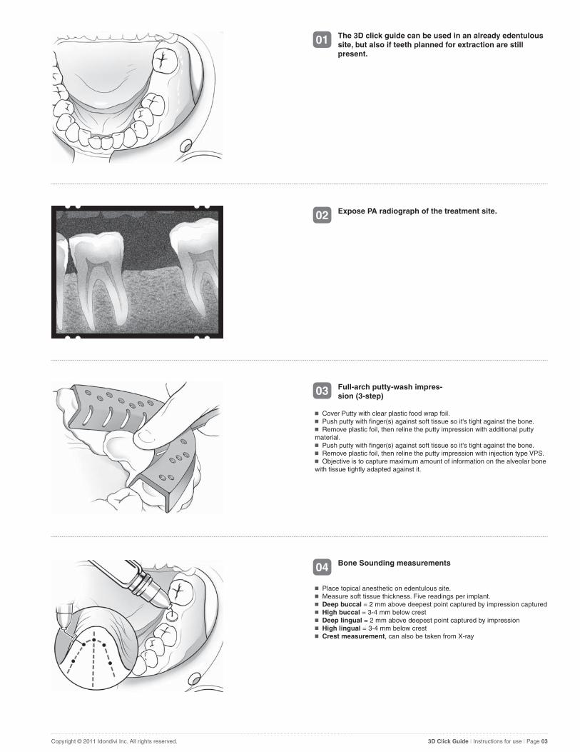
03 Full-arch putty-wash impres-sion (3-step)
� Cover Putty with clear plastic food wrap foil.� Push putty with finger(s) against soft tissue so it's tight against the bone.� Remove plastic foil, then reline the putty impression with additional putty material.� Push putty with finger(s) against soft tissue so it's tight against the bone.� Remove plastic foil, then reline the putty impression with injection type VPS.� Objective is to capture maximum amount of information on the alveolar bone with tissue tightly adapted against it.
01 The 3D click guide can be used in an already edentulous site, but also if teeth planned for extraction are still present.
02 Expose PA radiograph of the treatment site.
04 Bone Sounding measurements
� Place topical anesthetic on edentulous site.� Measure soft tissue thickness. Five readings per implant.� Deep buccal = 2 mm above deepest point captured by impression captured� High buccal = 3-4 mm below crest� Deep lingual = 2 mm above deepest point captured by impression� High lingual = 3-4 mm below crest� Crest measurement, can also be taken from X-ray

Copyright © 2011 Idondivi Inc. All rights reserved. 3D Click Guide | Instructions for use | Page 04
07 Cast fabrication and tooth wax–up
� Pour impression in Accutrac tray or Pindex using dental stone or VPS casting material.� Place denture tooth or wax-up.� Mark buccal gingival outline of the desired prosthetic outcome.� Top of the implant should in general be 2-3 mm below this line.
05 Record data from Bone Sounding measurements.
06 Cone beam computer tomography (cbct) as an alternative to bone sounding measurements.
VPS material is radio opaque. Take the CBCT while the patient is (still) wearing the impression. Otherwise a local impression can be made on the cast and transferred to the mouth when the patient is having the CBCT taken. The soft tissue is now easily related to the bone and critical structures. If desired an overlay can be drawn and superim-posed, or direct measurements can be transferred to the cast model.
08 Index fabrication
Create local impression of wax-up / denture tooth using silicone putty material.
Copyright © 2011 Idondivi Inc. All rights reserved. 3D Click Guide | Instructions for use | Page 05
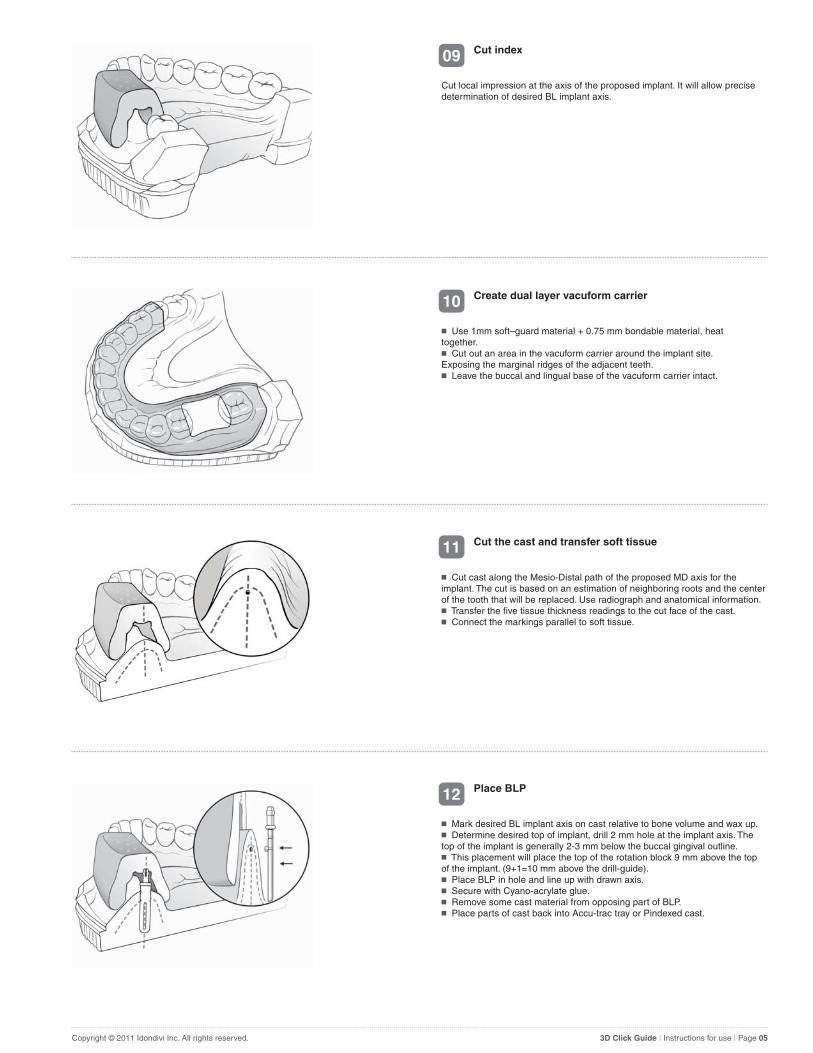
11 Cut the cast and transfer soft tissue
� Cut cast along the Mesio-Distal path of the proposed MD axis for the implant. The cut is based on an estimation of neighboring roots and the center of the tooth that will be replaced. Use radiograph and anatomical information.� Transfer the five tissue thickness readings to the cut face of the cast.� Connect the markings parallel to soft tissue.
09 Cut index
Cut local impression at the axis of the proposed implant. It will allow precise determination of desired BL implant axis.
10 Create dual layer vacuform carrier
� Use 1mm soft–guard material + 0.75 mm bondable material, heat together.� Cut out an area in the vacuform carrier around the implant site. Exposing the marginal ridges of the adjacent teeth.� Leave the buccal and lingual base of the vacuform carrier intact.
12 Place BLP
� Mark desired BL implant axis on cast relative to bone volume and wax up.� Determine desired top of implant, drill 2 mm hole at the implant axis. The top of the implant is generally 2-3 mm below the buccal gingival outline.� This placement will place the top of the rotation block 9 mm above the top of the implant. (9+1=10 mm above the drill-guide).� Place BLP in hole and line up with drawn axis.� Secure with Cyano-acrylate glue.� Remove some cast material from opposing part of BLP.� Place parts of cast back into Accu-trac tray or Pindexed cast.
Copyright © 2011 Idondivi Inc. All rights reserved. 3D Click Guide | Instructions for use | Page 06
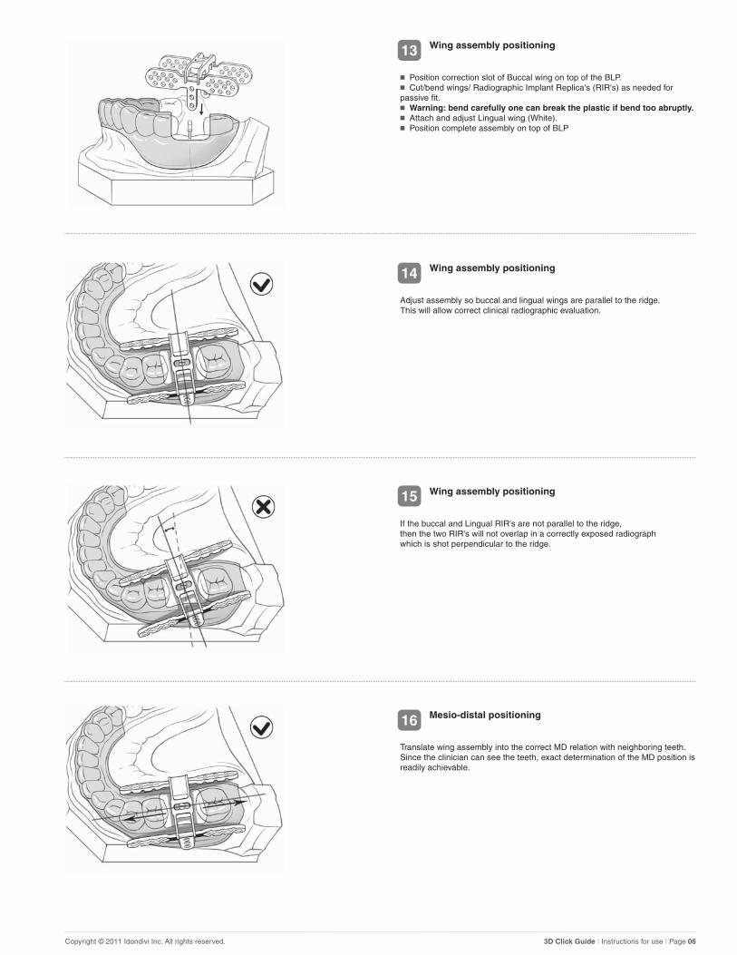
15 Wing assembly positioning
If the buccal and Lingual RIR's are not parallel to the ridge, then the two RIR's will not overlap in a correctly exposed radiographwhich is shot perpendicular to the ridge.
13 Wing assembly positioning
� Position correction slot of Buccal wing on top of the BLP.� Cut/bend wings/ Radiographic Implant Replica's (RIR's) as needed for passive fit.� Warning: bend carefully one can break the plastic if bend too abruptly.� Attach and adjust Lingual wing (White).� Position complete assembly on top of BLP
14 Wing assembly positioning
Adjust assembly so buccal and lingual wings are parallel to the ridge. This will allow correct clinical radiographic evaluation.
16 Mesio-distal positioning
Translate wing assembly into the correct MD relation with neighboring teeth. Since the clinician can see the teeth, exact determination of the MD position is readily achievable.
Copyright © 2011 Idondivi Inc. All rights reserved. 3D Click Guide | Instructions for use | Page 07
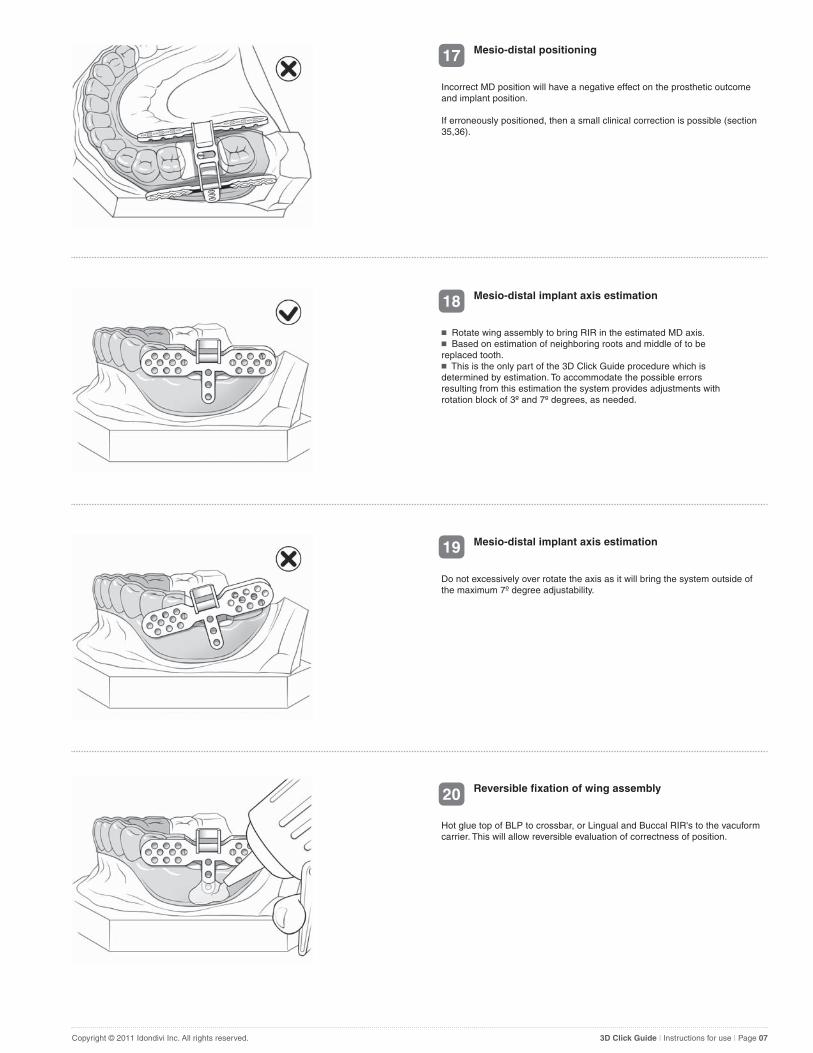
19 Mesio-distal implant axis estimation
Do not excessively over rotate the axis as it will bring the system outside of the maximum 7º degree adjustability.
17 Mesio-distal positioning
Incorrect MD position will have a negative effect on the prosthetic outcome and implant position.
If erroneously positioned, then a small clinical correction is possible (section 35,36).
18 Mesio-distal implant axis estimation
� Rotate wing assembly to bring RIR in the estimated MD axis.� Based on estimation of neighboring roots and middle of to be replaced tooth.� This is the only part of the 3D Click Guide procedure which is determined by estimation. To accommodate the possible errors resulting from this estimation the system provides adjustments with rotation block of 3º and 7º degrees, as needed.
20 Reversible fixation of wing assembly
Hot glue top of BLP to crossbar, or Lingual and Buccal RIR's to the vacuform carrier. This will allow reversible evaluation of correctness of position.
Copyright © 2011 Idondivi Inc. All rights reserved. 3D Click Guide | Instructions for use | Page 08
23 Remove surgical guide from cast
Remove guide from cast, polish as needed.
21 Permanent fixation of wing assembly
� Secure wings and RIR's with ortho-acrylic to create an irreversible solid connection.� Apply adequate acrylic to create appropriate support and stiffness.
22 Cut cross bar
� Cut crossbar section at the buccal side of the wing assembly, unclick from the lingual wing, and discard crossbar.� This exposes the retention rails.� Remove clear silicone protector.
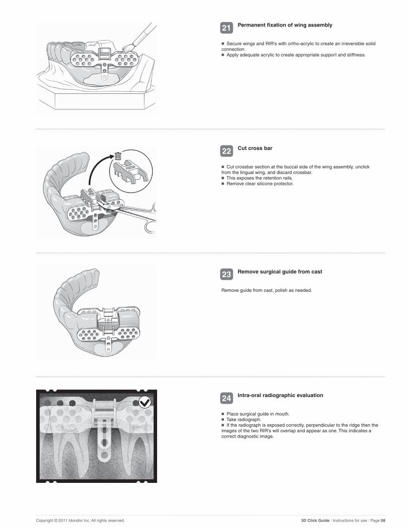
24 Intra-oral radiographic evaluation
� Place surgical guide in mouth.� Take radiograph.� If the radiograph is exposed correctly, perpendicular to the ridge then the images of the two RIR's will overlap and appear as one. This indicates a correct diagnostic image.
Copyright © 2011 Idondivi Inc. All rights reserved. 3D Click Guide | Instructions for use | Page 09
27 Evaluate need for rotational corrrection (7º degrees required)
� Radiograph correctly exposed. The RIR's overlap.� The axis of the RIR's is incorrect. The drill trajectory would hit the root.� A correction is needed.� In this case a 7º degree rotation block is selected.� WARNING: The 3º and 7º degree rotation block can correct both directions. Assure that the arrows indicate the direction to which you want to correct. To confirm correct angulation, take a radiograph with a radio opaque drill guide before drilling.
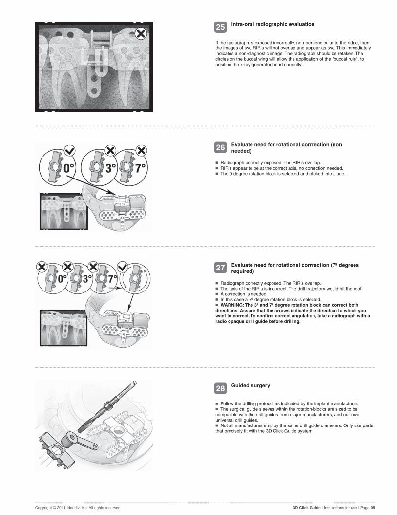
25 Intra-oral radiographic evaluation
If the radiograph is exposed incorrectly, non-perpendicular to the ridge, then the images of two RIR's will not overlap and appear as two. This immediately indicates a non-diagnostic image. The radiograph should be retaken. The circles on the buccal wing will allow the application of the "buccal rule", to position the x-ray generator head correctly.
26 Evaluate need for rotational corrrection (non needed)
� Radiograph correctly exposed. The RIR's overlap.� RIR's appear to be at the correct axis, no correction needed.� The 0 degree rotation block is selected and clicked into place.
28 Guided surgery
� Follow the drilling protocol as indicated by the implant manufacturer.� The surgical guide sleeves within the rotation-blocks are sized to be compatible with the drill guides from major manufacturers, and our own universal drill guides.� Not all manufactures employ the same drill guide diameters. Only use parts that precisely fit with the 3D Click Guide system.
Copyright © 2011 Idondivi Inc. All rights reserved. 3D Click Guide | Instructions for use | Page 10
31 Complete osteotomy
� Increasing drill diameters should be used with their respective drill guides to enlarge the osteotomy per protocol.� This schematic shows the use of the Flexistop system in conjunction with a drill with a fixed built in drill-stop.� The Flexistops system consists of rubber rings that allow 1.5 mm incremental reductions in length of drills with fixed built in drill-stops.
29 Initial osteotomy
� Drill with the pilot drill to a short and safe depth and evaluate the length of the osteotomy.� The top of the rotation block is 9 mm above the top of the implant. The drill guide is 1 mm thick, so the drill stop should be set at + 10 mm for accurate depth control. For example a 10 mm osteotomy requires the drill-stop to be set at 10+10 = 20 mm.
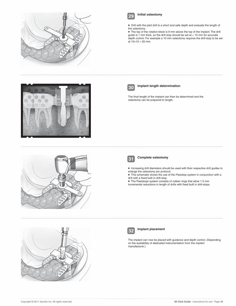
30 Implant length determination
The final length of the implant can then be determined and the osteotomy can be prepared to length.
32 Implant placement
The implant can now be placed with guidance and depth control. (Depending on the availability of dedicated instrumentation from the implant manufacturer.)

Copyright © 2011 Idondivi Inc. All rights reserved. 3D Click Guide | Instructions for use | Page 11
33 Implant placement
Implant placed with full guidance.
� Device will clip on retention rail and simulate the effect of a 7º degree rotation.� This will aid in the selection of the correct rotation block.� If 0º degree is not correct, 7º degree is too much, then it should be the in between 3º degree rotation block.
E 7º Degree Radiographic Implant Replica
Addendum
Copyright © 2011 Idondivi Inc. All rights reserved. 3D Click Guide | Instructions for use | Page 12
36 Mesio-distal translation correction
� Although rarely needed; if additional translation is required then the arm of the rotation block can be shortened as indicated.� This will allow translation over the retention rail in a mesio-distal plane, while maintaining all other variables unaltered.
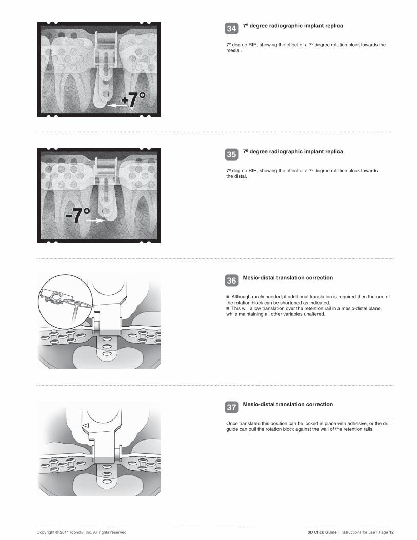
34 7º degree radiographic implant replica
7º degree RIR, showing the effect of a 7º degree rotation block towards the mesial.
35 7º degree radiographic implant replica
7º degree RIR, showing the effect of a 7º degree rotation block towards the distal.
37 Mesio-distal translation correction
Once translated this position can be locked in place with adhesive, or the drill guide can pull the rotation block against the wall of the retention rails.

Terms and Conditions
CAREFULLY READ THE FOLLOWING TERMS AND CONDITIONS ("AGREEMENT") BEFORE PURCHASING OR USING THE PRODUCT (AS DEFINED BELOW). THE PRODUCT IS SOLD BY IDONDIVI, INC. ("COMPANY") TO YOU, THE PURCHASER ("YOU"), SOLELY FOR USE AS SET FORTH BELOW. IF YOU DO NOT AGREE TO THE TERMS AND CONDITIONS OF THIS AGREEMENT, DO NOT PURCHASE OR USE THE PRODUCT. PURCHASING OR USING THE PRODUCT INDICATES THAT YOU ACCEPT THESE TERMS AND CONDITIONS.
I. SCOPE OF AGREEMENT. Company is selling the Product (as defined below) to You solely for use in the placement of endosseous dental implants when tissue contact will last less than 1 hour. "Product" means the 3D Click Guide sold to You by Company, which consists of 3 rotation blocks, Buccal-wing, Lingual-wing, Bucco Lingual Positioner, 7 degree Radiographic Implant Replica, 2x1.5 mm flexistops, 2x 3 mm flexistops and a multi gauge and /or universal drill guide kits, consisting of various sizes and quantities of drill guides.
2. RESTRICTIONS, PROPRIETARY RIGHTS AND FEEDBACK. You agree to promptly disclose to Company any flaws, errors, bugs or other problems You find in the Product. If You disclose to Company any suggested improvements or modifications of the Product (all such disclosures collectively, "Feedback"), then You agree that Company owns all right, title, and interest in and to the Feedback and all intellectual property rights inherent therein or related thereto. As such, You hereby assign to Company all right, title and interest in and to the Feedback. You further agree to do all acts reasonably required to perfect and enforce such rights.
3. LIMITED WARRANTY. Company warrants that for a period of ninety (90) days from the date You purchase the Product, the Product will (i) perform substantially in accordance with the end user documentation provided by Company to You in the Product's packaging; and (ii) be free from material defects in materials, workmanship and design. If the Product does not meet the foregoing warranty during such ninety (90) day period, Company's sole obligation, at its option, under this warranty is to repair the defect or deliver a replacement Product to You.
4. NO OTHER WARRANTIES. EXCEPT AS EXPRESSLY SET FORTH ABOVE, YOU AGREE THAT THE PRODUCT IS PROVIDED "AS IS." COMPANY MAKES NO OTHER WARRANTIES OF ANY KIND WITH RESPECT TO THE PRODUCT, EXPRESS OR IMPLIED, AND EXPRESSLY DISCLAIMS ANY IMPLIED WARRANTIES, INCLUDING WITHOUT LIMITATION THE IMPLIED WARRANTIES OF MERCHANTABILITY, FITNESS FOR A PARTICULAR PURPOSE OR NONINFRINGEMENT.
5. LIMITATION OF LIABILITY. TO THE FULLEST EXTENT PERMITTED BY APPLICABLE LAW, IN NO EVENT WILL COMPANY BE LIABLE FOR ANY: (i) CONSEQUENTIAL, SPECIAL, INCIDENTAL, INDIRECT, EXEMPLARY, PUNITIVE OR STATUTORY DAMAGES, INCLUDING, WITHOUT LIMITATION, LOSS OF REVENUES, BUSINESS OR PROFITS, OR (ii) AMOUNT IN THE AGGREGATE EXCEEDING US$1,000. THIS LIMITA-TION WILL APPLY EVEN IF COMPANY HAS BEEN ADVISED OF THE POSSIBILITY OF SUCH DAMAGE. YOU AND COMPANY ACKNOWL-EDGE THAT THIS IS A REASONABLE ALLOCATION OF RISK.
6. MISCELLANEOUS. This Agreement sets forth the entire agreement and understanding of the parties relating to the subject matter herein and merges and supersedes all prior or contemporaneous oral or written discussions between them. This Agreement shall be governed by the laws of the State of California without regard to conflict of laws principles. The parties hereby submit to the personal jurisdiction of, and agree venue is proper in, the state courts located in Santa Clara County, California and the federal courts located in the Northern District of California, as appropriate. Any suit arising out of or related to this Agreement shall be brought exclusively in such courts. If any provision of this Agreement is held by a court of competent jurisdiction to be illegal, invalid, or unenforceable, that provision shall be limited or eliminated to the minimum extent necessary so that this Agreement shall otherwise remain in full force and effect and enforceable. No amendment, modification or waiver of any provision of this Agreement shall be effective unless in writing and signed by the parties. You may not assign this Agreement (by operation of law or otherwise), without the prior written consent of Company. The parties are independent contractors, and nothing in this Agreement shall be construed to create a joint venture or partnership or otherwise give rise to fiduciary obligations between the parties. Each party will comply with all applicable laws, statutes, rules and regulations.
Copyright © 2011 Idondivi Inc. All rights reserved. 3D Click Guide | Instructions for use | Page 13