thank you for choosing tronxy products! we will serve you
TRANSCRIPT


Thank you for choosing TRONXY products!
We will serve you whole heartedly!
Please read the instruction carefully
Please visit tronxy.cn for more information
After- sale service:[email protected]
TEL:+86-755-89968500

Pay attention Please read this instruction carefully and follow the safety instruction.
When the 3D printer is working, it will produce high temperature.Do not touch working parts or extruder directly.After printing, the working part may still be in the high temperature state.Please wait patiently for the working parts and the print model to cool down before removing the model from the print platform.
Please use the 3D printer in a spacious and well-ventilated environment.
The recommended ambient temperature for 3D printers is 8° c-40 °C, and the humidity is 20%-80%. Using outside this range may bring bad printing effects.
In case of emergency, could turn off the power of the 3D printer directly.
3D printers contain working parts that move at high speeds, so be wary of pinching your hands.
When removing the model from the print platform, be careful not to swipe sharp objects at your finger.
Assemble the 3D printer or polish the model. suggest Wear goggles.
Please pay attention to the protection of 3D printer against rain and moisture.
Keep children away from the machine when it running It is not recommended to run a 3D printer when left unattended.

Catalogue 1. Introduction to parameters ……………………………1
2. Introduction to machine structure …………………2
3. Packing list ……………………………………………………3
4. Installation instructions …………………………………4
5. Interface operation and printing …………………17
6. Slice software ………………………………………………20
7. Fault cause analysis ………………………………………23

Print parameters
Print principle: FDM (Fused deposition molding)
Print size: 330× 330×400 (mm3)
Print accuracy: 0.1-0.4 mm
Positioning accuracy: X/Y 0.0125mm,Z 0.002mm
Nozzle quantity: 1
Nozzle size: 0.4 mm
Print speed: 20~100mm/s (suggest 60mm/s)
Moving speed: 100mm/s
Filament: PLA, TPU, ABS, wood, pc,HIPS, wooden filament etc.
Temperature parameters
Environmental temp: 8℃ - 40℃
Nozzle temp: Max260℃
Heat bed temp: support
Software Slice software: Cura
Input format: .STL .OBJ
Output format: GCode
Connection: TF card, USB cable(Suitable for skilled users)
Power supply Power input: 110V/220V AC, 50/60Hz
Power output: 24V/15A DC
Physical parameter
Machine size: 580mm×645mm×660mm
Machine weight: ~14.5kg
1. Machine parameter
1

2
2. Machine details
④ ⑤
①
②
③
⑥
⑦ ⑧
⑨
⑩
⑪
⑫
⑬
⑮
⑭
⑰
1.Touch screen 2.Z1motor 3.Heatbed 4.Y axis switch
5.Y-right guide rail 6.Y-right sliding parts 7.Xmotor
9.Ymotor 10. Yleft sliding parts 11. Y-left guide rail
13.polish rod
12.lead screw
14.Z2motor 16.TF interface
17.USB interface 18.PIN line interface 19.power switch 20.power supply
15.aluminum frame
㉑ ㉒
21.switch lines box 23.filament run-out detection 22.Titan extruder
8.extruder head
㉓ ⑯ ⑱ ⑲
⑳ controller box

3. Packing list
2040aluminum profiles 530mm
4pcs
2020aluminum profiles
530mm4pcs 460mm2pcs
OSG External double axis guide rail
-Y axis 460mm 2pcs
OSG External double axis guide rail
-X axis 480mm 1pcs
polished rod 528MM 4pcs lead screws
453MM 2pcs
beams/footlock 2pcs
left and right sliding parts
print head left /right belt pulley
parts X/Y axis motors
Zaxis motor parts
Titan extruder component bag
1pcs controller & touch
screen belt bag
filament (Color random)
power line seal
(Color random) aluminum plate with
balck sticker heat bed
screws bag 4pcs
shovel (Color random)
USB cable Tools bag reader+TFcard
YZswitch parts 1pcs
filament run out detection parts
1pcs
drag chain parts 1pcs
3
After receiving the goods, please check the accessories according to
the packing list. If you have any questions, please contact customer
service.
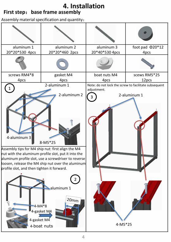
4. Installation First step:base frame assembly
Assembly material specification and quantity:
aluminum 1 20*20*530 4pcs
aluminum 2 20*20*460 2pcs
aluminum 3 20*40*530 4pcs
foot pad Φ20*12 4pcs
screws RM4*8 4pcs
gasket M4 4pcs
boat nuts M4 4pcs
scews RM5*25 12pcs
Assembly tips for M4 ship nut: first align the M4 nut with the aluminum profile slot, put it into the aluminum profile slot, use a screwdriver to reverse loosen, release the M4 ship nut over the aluminum profile slot, and then tighten it forward.
1 2-aluminum 1
2-aluminum 2
4-aluminum 3 8-M5*25
2
aluminum 1
3
Note: do not lock the screw to facilitate subsequent adjustment.
2-aluminum 1
4-M5*25
4
4-M4*8
4-gasket M4
4-gasket M4
4-boat nuts

Assembly material specification and quantity:
base frame 1pcs
Y axis guide rail 20*20*460 2pcs
left sliding parts 1pcs
right sliding parts 1pcs
screws RM5*25 4pcs
Second step: Sliding plate assembly
1.Take out the Y axis guide rail and put it into the left and right sliding parts respectively, as shown in the figure.
2.Note the direction of the slide. The front of the slide should be on the same side as the counterbore of the guide, as shown in the figure.
1
Pay attention the direction of the counterbore
Screw RM5*25 do not lock tight the Y axis guide rail, which is convenient for subsequent adjustment
left sliding parts
right sliding parts
2
4-M5*25
5
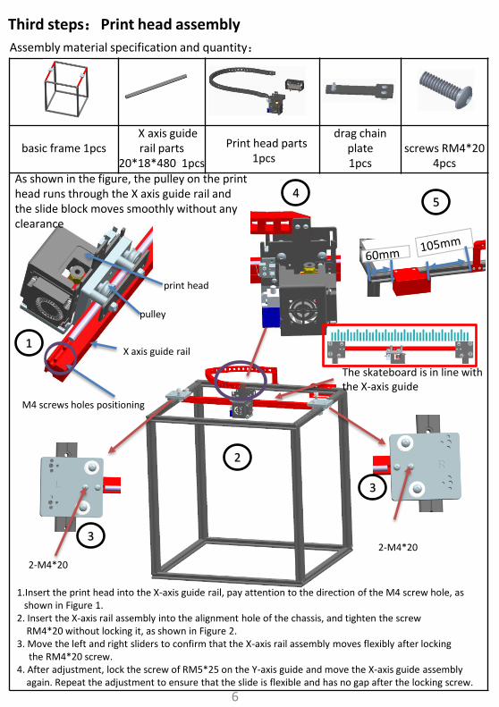
Assembly material specification and quantity:
basic frame 1pcs
X axis guide rail parts
20*18*480 1pcs
Print head parts 1pcs
drag chain plate 1pcs
screws RM4*20
4pcs
Third steps:Print head assembly
1
As shown in the figure, the pulley on the print head runs through the X axis guide rail and the slide block moves smoothly without any clearance
pulley
M4 screws holes positioning
print head
2-M4*20
2-M4*20 3
3
2
4 5
X axis guide rail
1.Insert the print head into the X-axis guide rail, pay attention to the direction of the M4 screw hole, as shown in Figure 1. 2. Insert the X-axis rail assembly into the alignment hole of the chassis, and tighten the screw RM4*20 without locking it, as shown in Figure 2. 3. Move the left and right sliders to confirm that the X-axis rail assembly moves flexibly after locking the RM4*20 screw. 4. After adjustment, lock the screw of RM5*25 on the Y-axis guide and move the X-axis guide assembly again. Repeat the adjustment to ensure that the slide is flexible and has no gap after the locking screw.
The skateboard is in line with the X-axis guide
6

Assembly material specification and quantity:
basic frame parts 1pcs
right wheel parts 1pcs
left wheel parts 1pcs
X motor 1pcs
Y motor 1pcs
Step 4:XY axis motors and wheels assembly
1. Lock and fix the assembled parts in the position as shown in the figure
Assembly tips for M4 ship nut: first align the M4 nut with the aluminum profile slot, put it into the aluminum profile slot, use a screwdriver to reverse loosen, release the M4 ship nut over the aluminum profile slot, and then tighten it forward
7
This screw positioning Don't need to tighten
This screw positioning Don't need to tighten

Assembly material specification and quantity:
basic frame 1pcs
Belt 2pcs
Ties 4pcs
Step 5:Belts assembly
Belt tying diagram
4-M3*3
1.As shown in the figure, after adjusting the distance between the motor gear and the belt, lock the 2 rice screws on the gear. 2. Also assemble the second belt, the tension of the second belt should be equal.
8
X motor
Y motor
Note: Synchronization wheels on X, Y axis motors Height should be adjusted by itself. Be sure to install the belt Each belt is on the same planeUp.

Assembly material specification and quantity:
beams 2pcs
Linear bearing 4pcs
copper linear bearing
2pcs
screws RM3*12 24pcs
Step 6:Linear bearing assembly
12-M3*12
9

Assembly material specification and quantity:
basic frame 1pcs
Z axis motor parts 2pcs
foot lock parts 2pcs
bearing base parts 2pcs
polish rod Φ8*528 4pcs
lead screwT8*453
2pcs
screws RM4*20
8pcs
screws RM4*8 4pcs
Step 7:Z axis parts assembly
4-M4*8
2-M3*3
4-M4*4
3
10
4-M4*20
M3 hole is on the outside
2
1 polish rod
polish rod
lead screw
bearing base parts
As shown in Figure 1, assemble the assembly, put the assembly into the frame as shown in Figure 2, and align the holes to lock the screws.
Adjust the verticality of the polished rod and tighten the screws

Assembly material specification and quantity:
basic frame 1pcs
Z axis motor parts 2pcs
L angle code 1pcs
screws RM4*6 2pcs
boat nuts M4 1pcs
Step 8:Controller box assembly
1
Separate the screen from the host and Fix the M4 boat nut on the bottom rack as shown
2-boat nuts
2-M4*6
2
boat nuts
2-M4*6
boat nuts
11
Fix the boat nut on the main box to the bottom shelf with the locking L corner code, as shown in the figure
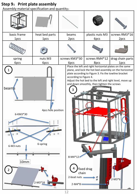
Assembly material specification and quantity:
basic frame 1pcs
heat bed parts 1pcs
beams 2pcs
plastic nuts M3 6pcs
screws RM3*16 2pcs
spring 6pcs
nuts M3 6pcs
screws KM3*30 6pcs
screws RM4*12 8pcs
drag chain parts 1pcs
Step 9:Print plate assembly
1
4pcs hole position
6-KM3*30
6-spring 6-M3 nuts
10mm
2-M3*16
3
2
8-M4*12
2-boat nuts
2-M4*8
2-M3*6
fixed drag chain
4
beams
12
Place the left and right horizontal plates on the same plane, and lock the hot bed assembly on the horizontal plate according to Figure 3. Fix the towline bracket according to Figure 4. Adjust the hot bed to the left and right level, move up and down smoothly, then tighten the screws

Assembly material specification and quantity:
basic frame 1pcs
filament run out detection parts
1pcs
Titan extruder 1pcs
screw RM4*6 4pcs
boat nuts M4 2pcs
nuts M4 2pcs
Step 10:Feeding motor assembly
1 Assemble Titan extruder to filament runout detection parts
2-RM4*6 2-boat nuts
2 10MM 2-boat nuts 2-RM4*8
As shown, lock the Titan extruder assembly to the basic frame
13
RM4*8
RM4*8

Assembly material specification and quantity:
printer 1pcs
YZ switch parts 1pcs
bracket part 1pcs
screw RM5*12
screw RM4*6
4pcs
boat nuts M4 4pcs
Step 11:Switch and filament bracket assembly
feeding tube
Note: the feed tube of the print head is not inserted at the bottom, which may lead to blockage.
2-RM4*6 2-boat nuts M4
YZ switch parts
2-RM4*6 2-boat nuts M4
2-M5*12
14
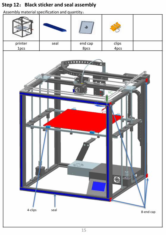
Assembly material specification and quantity:
printer 1pcs
seal end cap 8pcs
clips 4pcs
Step 12:Black sticker and seal assembly
4-clips seal 8-end cap
15

Step 13:Wiring
X-motor
Z2 motor heat bed
controller box
Y axis switch
controller box
heatbed heating
heat bed
Z2 motor
Y motor
E motor
X motor
filament run out detection
Z1 motor
Y axis switch
Y axis switch
filament break detection
16
filament break detection
E motor
Z1motor
Y-motor

17
5. Interface operation and printing

18
Unload consumables:
Click 23/0 23/199
After waiting for temperature up to 180 ℃, consumables through the run out detection, extruder and Feed pipe until the nozzle has consumable extrusion, as shown in the figure below:
Print test:
Click →“Testing file”→ ,start print。
If the first layer is not sticky, the nozzle is on the high side and the platform can be raised appropriately; If the nozzle has a small amount of thread, the nozzle is on the low side and the platform can be appropriately lowered.

19
Manual leveling:
Click the four points of ABCD in the figure below, the print head will move to the corresponding position, and then adjust the leveling nut M, so that the interval between the nozzle and the platform is a piece of A4 paper. After adjusting the four points in turn, it needs to be verified again. If the interval is appropriate, the leveling is completed.
A B
C D
M Auto leveling:
① Automatic leveling for automatic leveling version of the machine, the manual version can not be use. Click the leveling function in the figure to automatically pop up the interface, select "automatic leveling",jump out of the figure (1) interface, and start leveling. After the Detection is completed, the error value of each point will be displayed. If the value is greater than 0.5, adjust the leveling nut in the corresponding area, and then reset until all values are less than 0.5, then the automatic leveling is completed
② Then click “Z offset”, the print head will move to the middle of the platform, observe the height of the nozzle and platform, and then click ①②,make the distance between the nozzle and platform for a piece of A4 paper height, then click ③, reset the zero, so that the end of leveling.
Figure (1)
autolevel
③
①
②
9
20
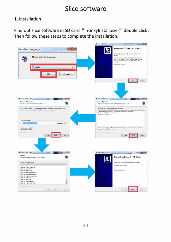
Slice software
1. Installation
Find out slice software in SD card“TronxyInstall.exe ”double click,Then follow these steps to complete the installation.

2. How to use slice software
① 、Type setting: follow the steps below to complete the setting.
①
②
③
④
⑤
⑥
21

22
Layer thickness : 0.1-0.3mm Print temp : PLA - 200 ℃ ABS - 240 ℃ Heatbed temp : PLA - 50℃ ABS - 80 ℃ Print speed : 20-120mm/s (suggest 60mm/s) Support : Choose according to the model structure Platform support: It is recommended to use the model when the bottom contact is small
Some parameters are set for reference:
② 、Parameter setting:(The following figure gives the reference value, according to their own needs can be modified)

23
2. The contents of the SD card cannot be read?
1)Check the card reader if damage. 2)If the connect computer show empty, please format the SD card and try again. 3)Check whether the SD card is inserted into the socket correctly. 4)The filename has an illegal character, please rename it. 5)Please replace the damaged SD card and try again.
3. if the print head does not produce enough material or does not produce enough material? 1)Check whether the print head temperature have not reached 200 ℃ above (PLA), led to consumable cannot squeeze, waiting for the temperature rises to the set target. 2)Check whether the filaments are knotted, which leads to unsmooth feeding. 3)Check whether the filaments or pipes are not inserted in place, resulting in the failure of feeding. 4)Check whether the temperature of the print head is too high, which leads to excessive softening of filaments and can't be extruded normally. 5)Check whether the diameter of filaments is inconsistent with the diameter set in the slicing software, so that the amount of extrusion filaments is not enough. 6)Check whether the consumables are blocked by dirt or nozzle blocked during extrusion. 7)Replace with better quality filaments.
1. Machine cannot start ? 1)Check the power line and other wires connect correct or not. 2)Check whether the supply voltage matches the local standard. 3)Check whether the screen or power supply is damaged and replace in time. 4)Check the wires if damage or breakage. 5)Check whether the power fuse is burnt out.
Fault cause analysis

24
4. If the first layer upwarp ? 1)Check that the hot bed has been leveled. 2)Check the surface of the hot bed for dirt. 3)Check whether the distance between the nozzle and the platform is too high, resulting in insufficient adhesive force. 4)Check the hot bed for adequate temperature. 5)Check the first layer of the slicing software to see if it is printing too fast.
5. The model is not easy to take off? 1)Heating the hot bed to 50-70 ℃, and after cooling to try again, or use the shovel. 2) It is recommended to buy TRONXY magnetic stickers.
6. Can't heat it up?
1)Check the heating rod and thermistor for poor contact or damage. 2) Check that the slice software has set the target temperature. 3) Check whether the thermistor wire falls off.
7. Motor out of step? 1)Check the tightness of the belt, whether the pulley is not locked. 2)Check the current voltage. 3)Check X/Y/Z axis motion is smooth. 4)Print speed too fast. 5)Environment temp too high. 6)Need flash the firmware.
8. Abnormal motor noise or vibration?
1)Check whether the motor line is in bad contact, loose or wrong connection. 2)Motor temperature is too high. 3)Check whether the motor is damaged. 4)Flash the firmware. 5)The printing load is too heavy.

25
9. Model dislocation and fault 1)Nozzle feeding not smoothly, please clean the nozzle or replace the nozzle 2)Check that if the printing speed is too fast 3)The quality of filaments is poor, please replace with new filaments
10. Abnormal sound and vibration of filaments feeding motor 1)Please check whether the nozzle is blocked 2)The nozzle feeding is not smooth, please clean the nozzle 3)Whether the software Settings are incorrect 4)Check whether the motor does not work 5)Check the motor working or not or feeding gear is not working
11. Screen related questions
1)No screen/blue screen, please restart or check whether the cable is plugged in 2)Touch screen malfunction, check whether the screws are installed too tight 3)Garbled/splash screen, static, ground connection or restart
12. Motherboard related issues 1)The wiring is not responding. Please check the wiring installation 2)Automatic shutdown restart, may be abnormal firmware or module of “resume print after power failure” damaged 3)Lack of heat dissipation, please lower the ambient temperature 4)No response due to motherboard damage
13. Unable to connect to printer 1)Check that the driver is not installed or properly installed 2)The serial port was not selected correctly 3)The software parameters do not match

26