th250 and th150 - home - thawzall urner/genisys ontroller features page 31– 34 th250 wiring...
TRANSCRIPT

1
Manufactured by Thawzall, LLC
104 Donovan Drive
P O Box 158
Alexandria, MN 56308, USA
T 320.759.1588 24/7 Tech Support 888.757.3545
F 320.759.1583
www.thawzall.com E-mail: [email protected]
TCH250 and TCH150

2
3
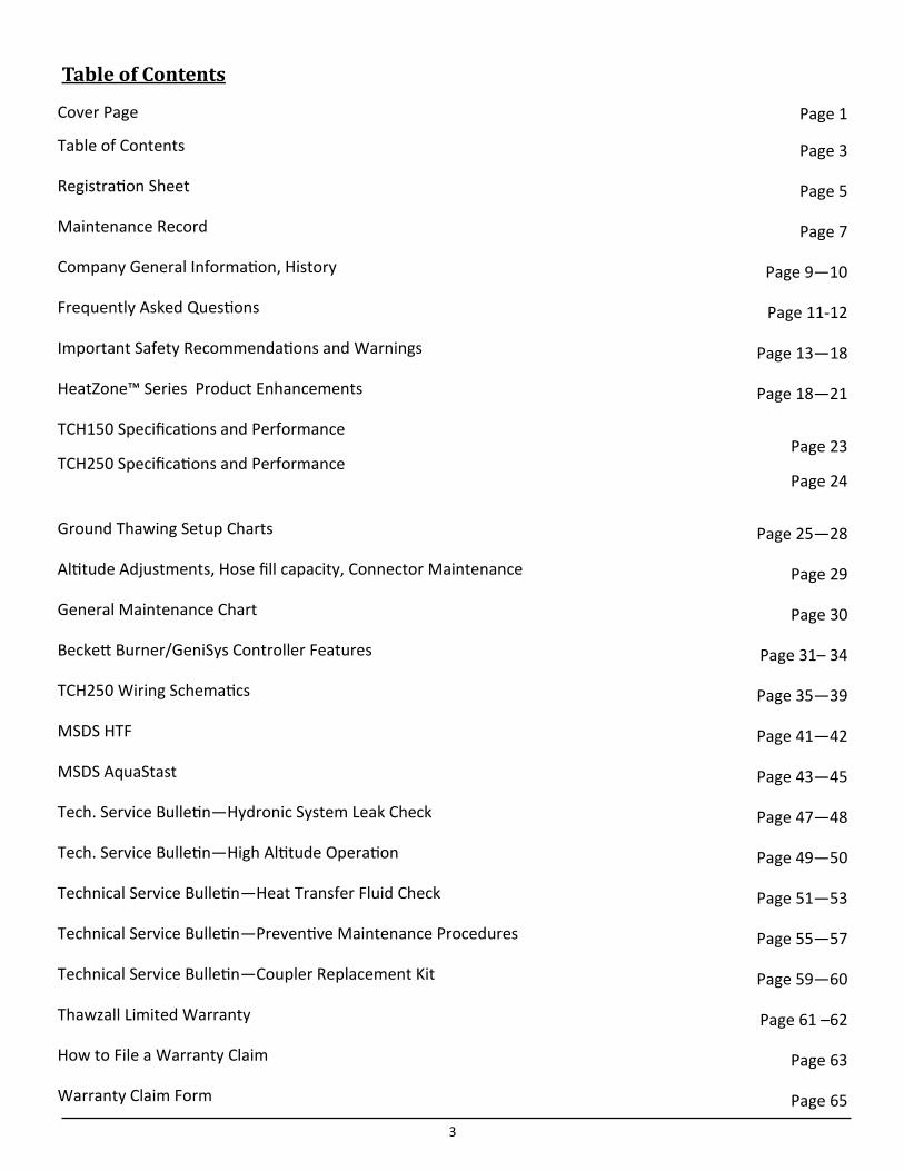
Table of Contents
Cover Page Page 1
Table of Contents Page 3
Registration Sheet Page 5
Maintenance Record Page 7
Company General Information, History Page 9—10
Frequently Asked Questions Page 11-12
Important Safety Recommendations and Warnings Page 13—18
HeatZone™ Series Product Enhancements Page 18—21
TCH150 Specifications and Performance
TCH250 Specifications and Performance
Page 23
Page 24
Ground Thawing Setup Charts Page 25—28
Altitude Adjustments, Hose fill capacity, Connector Maintenance Page 29
General Maintenance Chart Page 30
Beckett Burner/GeniSys Controller Features Page 31– 34
TCH250 Wiring Schematics Page 35—39
MSDS HTF Page 41—42
MSDS AquaStast Page 43—45
Tech. Service Bulletin—Hydronic System Leak Check Page 47—48
Tech. Service Bulletin—High Altitude Operation Page 49—50
Technical Service Bulletin—Heat Transfer Fluid Check Page 51—53
Technical Service Bulletin—Preventive Maintenance Procedures Page 55—57
Technical Service Bulletin—Coupler Replacement Kit Page 59—60
Thawzall Limited Warranty Page 61 –62
How to File a Warranty Claim Page 63
Warranty Claim Form Page 65

4

5
Operators Manual
For model:
TCH 250/TCH150 Please record the following information from your new Thawzall for future reference. This in-
formation is required for all warranty claims.
Purchase date: ______/______/_______ Generator make: _____________________________
Machine model:________________________ Generator KW:__________________________________
Machine serial number:________________ Generator Serial #:_____________________________
Serial number located on trailer pull tube.
Manufactured by Thawzall, LLC
P. O. Box 158
104 Donovan Drive
Alexandria, MN 56308
Phone 320.759.1588 Fax: 320.759.1583 Tech Support 888.757.3545
Website:www.Thawzall.com E-Mail: [email protected]
*Older Models similar are H150, H250 and H250SL.

6
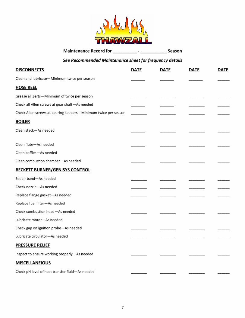
7
Maintenance Record for __________ - ___________ Season
See Recommended Maintenance sheet for frequency details
DISCONNECTS DATE DATE DATE DATE
Clean and lubricate—Minimum twice per season _______ _______ _______ ______
HOSE REEL
Grease all Zerts—Minimum of twice per season _______ _______ ________ ______
Check all Allen screws at gear shaft—As needed _______ _______ ________ ______
Check Allen screws at bearing keepers—Minimum twice per season ________ ________ ________ ______
BOILER
Clean stack—As needed _______ ________ ________ ______
Clean flute—As needed _______ ________ ________ ______
Clean baffles—As needed
Clean combustion chamber—As needed _______ ________ ________ ______
BECKETT BURNER/GENISYS CONTROL
Set air band—As needed ________ ________ ________ ______
Check nozzle—As needed ________ ________ ________ ______
Replace flange gasket—As needed ________ ________ ________ ______
Replace fuel filter—As needed
Check combustion head—As needed ________ ________ ________ ______
Lubricate motor—As needed
Check gap on ignition probe—As needed ________ ________ ________ ______
Lubricate circulator—As needed ________ ________ ________ ______
PRESSURE RELIEF
Inspect to ensure working properly—As needed ________ ________ ________ ______
MISCELLANEIOUS
Check pH level of heat transfer fluid—As needed ________ ________ ________ ______

8
9
Registered trademarks of Thawzall, LLC
COMPANY GENERAL INFORMATION
Mission Statement
It is the mission for Thawzall to continue to derive quality and innovate while securing a larger market
share and become the brand of choice recognized by all major rental companies and their contractor
and oil field service customers, for providing the most fuel efficient rental-store friendly glycol and
flameless heaters.
VISION STATEMENT
Thawzall’s vision is fairly simple. As a team, we want to provide the very best equipment to our valued
customers. Our relationships within our team and with our customers are faith based and predicated
on honesty, trust, fidelity and respect. Balance sheet growth and employee personal growth are tandem
precepts Thawzall intertwines as it prepares for the future. At the end of the day, Thawzall wants a bet-
ter world for its customers and its employees.
History of Thawzall, LLC
The idea of a portable hydronic heating system was conceived and named Thawzall in an Alexandria
Minnesota workshop in 1996 by a Norwegian plumber who had a contractor friend who was behind
schedule on a construction site when the winter freeze-up caught him off guard.
10
The plumber, Jerome Jakobson, developed his version of a portable hydronic heat system using a low
pressure closed loop system. The first of hundreds of machines to come was produced that first win-
ter. Because Jakobson felt that he and a better idea than a competing model, he applied for and re-
ceived patent #5,964,402 for his portable hydronic heater in 1999. This patented system uses a mani-
fold fluid distribution system that features quick disconnects and multiple heat zones.
Jakobson, an avid hunter and fisherman, decided to sell his company, known then as T.H.E. Machine
Company, to a group of five local investors from the Alexandria Minnesota area—in order to pursue
his passions. On July 1, 2007, the company was formed with new ownership and management and be-
came known as Thawzall, LLC.
The new management team is committed to listening to its customers for their ideas regarding prod-
uct innovation and simplicity. By listening carefully to our customers, we are confident that in the next
generation, Thawzall heat units will exceed our customers’ expectations and set new standards for
quality and innovation in the industry for portable hydronic and flameless heater technology.
All Thawzall employees are committed to excellence in manufacture and customer satisfaction. We
take great pride with every machine we build!
Thank you for investing in a Thawzall portable heater!
David Reller—General Manager
Steve Knisley—Sales
Neil Beilke—Technical Service Manager
Jeremy Guhlke—Operations Manager
Helen Berner—Purchasing and Inventory Manager
Karen Weis—Office Manager
History of Thawzall, LLC, cont.
11
Q: What can I do with a Thawzall Hydronic heater?
A: 1) Remove ground frost, 2) Prevent ground frost, 3) Use as a temporary heat source, 4) Cold weather concreting
Q: How does it work?
A: TCH 250/150 utilizes a top draft, high efficiency oil fired furnace which heats water/propylene
glycol (HTF) and distributes the HTF through the patented multi-zone manifold system thru a
series of 600 foot. industrial hydronic hoses in a low pressure closed loop system. Thawzall us-
es an automatic tempering valve to cover the various temperatures needed for Thaw, Cure and
Heat modes. Under no circumstances, will the furnace ever need to be adjusted down as the
electronic tempering valve can adjust the temperature delivery needed for the specific applica-
tions.
Q: How long does it take to remove frost?
A: Up to 12 inches of frost can be removed in a 24 hour period depending on layout of hose, insu-
lation used, ambient outside temperature and soil conditions.
PERFORMANCE
THAW AND CURE performance in the field is affected by a wide range of factors which include:
Soil type
Moisture content in the soil
Hose spacing
Thermal rating of the covering construction blankets
Outside ambient temperatures
HEAT performance in interior work spaces is also affected by several factors which include:
Outside ambient temperature
Heat loss
Volume of space to be heated and type of heat exchanger used
FREQUENTLY ASKED QUESTIONS
12
Q: Can Thawzall operate at high altitudes?
A: Yes, but operation at high altitudes may require adjustments—see High Altitude section.
Q: What kind of vehicle do I need to tow a Thawzall?
A: A minimum of 3/4 ton truck with a brake controller. Please see Specifications section.
Q: What type of fuel does the Thawzall use?
A: #1 fuel oil is preferred and if not available, then winter blend with anti-gelling additives.
Q: What type of power is required to operate the Thawzall?
A: 120 volt ac, 20 amps. The burner may not fire with less than 112 volts!
Q: How long can I expect a tank of fuel to last?
A: Depending on ambient temperature, work zone insulation and soil conditions, the average
fuel consumption is roughly 1 GPH without the generator and with the generator is about 1.6
GPH.
FAQ, Continued

13
14
OUTSIDE SAFETY FEATURES
Your Thawzall is equipped with DOT Certified outside LED lights, reflectors, safety-chains and elec-
tronic.
Break-away brakes.
Make use of these features:
Before towing the trailer, be sure that all the lighting is connected and working
Connect the safety chains to the towing vehicle
Connect the small cable from the break-away switch to the towing vehicle
Close the fuel valve at the bottom of the fuel tank on your Thawzall
PARKING YOUR THAWZALL
Avoid unexpected movement of your Thawzall:
Avoid parking on hills
Use blocks or wheel chucks to prevent movement
Always use the jack to support the hitch
TOWING YOUR THAWZALL
Tow safely:
A ¾ ton truck with a brake controller is recommended for towing the TCH 250/150.
Thawzall axles, wheels and tires are rated to travel at legal posted speeds on the highway
Connect safety-chains, lights and brake cable to towing vehicle
Thawzall trailers are equipped with electronic break-away brakes in case the trailer should be-
come disconnected from the towing vehicle. Trailer brakes will apply automatically
Failure to connect trailer in a safe manner could result in a serious accident or death
Always verify that the hitch ball size on the towing vehicle matches the size of the coupler on the
Thawzall trailer
GENERAL OPERATING INSTRUCTIONS
Do not operate your Thawzall without instruction and understanding the startup and shut down
procedures thoroughly—If you do not understand these instructions, call Thawzall Technical
Support—888.757.3545
IMPORTANT SAFETY RECOMMENDATIONS AND WARNINGS
15
Keep your machine in proper working condition. Unauthorized modifications to the machine may
impair the function and/or the safety and affect the life of the machine.
Wear hand protection while handling hot hoses and disconnects
HOSE REEL DANGER. Be very careful to keep hands and gloves clear from the hose reel
when rewinding the hose. A glove can get caught between hoses which may cause serious bodi-
ly injury.
Close ball valves on manifold when coupling or uncoupling the hoses to avoid accidental flu-
id loss and spillage or possible injury from hot liquid
No loose clothing. Do not wear loose clothing that can get caught in the hose reel or on lev-
ers or latches on your Thawzall.
Do not use gasoline or kerosene to fire the furnace on your Thawzall. This may cause explo-
sion which may result in serious injury or death. Only #1 fuel oil or a winter blend of fuel oil is
recommended for the furnace.
GFI Outlet. Always plug the electrical cord from your Thawzall into a GFI protected outlet.
Failure to do so could cause shock or electrocution.
Safety glasses. Always wear safety glasses when operating your Thawzall, especially when
connecting and disconnecting hoses, fueling or maintaining the battery on the optional genera-
tor.
Caution and Warning decals. Carefully observe and maintain all of the caution and warning
decals placed on your Thawzall machine. They are there to ensure proper operation of the
Thawzall and your safety!
Never “hot-wire any of the electrical wiring on your Thawzall or optional generator. Wiring
circuits are carefully designed to provide for safe Startup and operation of the furnace, pumps
and hose reel. Any alteration may cause an unsafe condition and could cause any or all compo-
nents to malfunction or operate out of sequence.
Operate only OUTDOORS! Never operate and engine or furnace inside a building without
proper venting of the exhaust to the outside. Carbon monoxide poisoning and asphyxiation
may occur if exhaust is inhaled.
HANDLE FUEL SAFELY
Avoid fires by handling fuel with care. Both diesel fuel used in the generator and #1 fuel oil
or a winter blend of fuel oil used in the furnace are extremely flammable!
Do not refuel the machine while smoking or while an open flame or sparks are near the re-
fueling point! Do not refuel while the generator or furnace is running.
A clean machine is a safe machine. Prevent fires by keeping your Thawzall clean of accumulated
trash, grease and debris. Clean up spilled fuel properly.
GENERAL OPERATING INSTRUCTIONS, cont.
16
Direct exposure to hazardous chemicals can cause injury. Potentially haz-ardous chemicals used in your Thawzall include, grease, paint and adhe-sives. Grease, paint and adhesives are espe-cially toxic when heated.
Please read with care the Material Safety Data Sheets (MSDS) provided in this manual. They pro-
vide specific details on the products used in you Thawzall, physical and health hazards, safety
procedures and emergency response techniques.
Check the MSDS sheets before operating your Thawzall so you will know the risks and first
aid techniques in case of an accident.
Keep emergency phone numbers for doctors, ambulance service, hospital and fire department
near your phone.
SAFETY INCLUDES PREVENTITIVE MAINTENANCE
Remove paint and adhesives before welding or heating.
Avoid heating near pressurized pipes and hoses, and near a fuel tank.
Dispose of waste properly. Improperly disposing of waste including HTF (Heat transfer flu-
id), grease, and plastics, filters and batteries, threaten the ecology of the environment.
Do not pour HTF on the ground, down a drain or into any water source. Inquire about the
proper way to dispose of wastes in your area, at your recycling center.
HANDLING BATTERIES SAFELY
Battery gas can explode. Keep sparks and flames away from the battery on the generator on your Thawzall
Never place a metal object across the battery posts
Always disconnect the grounded (-) battery clamp first and re-connect it last
Battery acid is poisonous and can burn skin and eat holes in clothing and cause blindness if
splashed into the eyes
Flush contaminated skin with water and baking soda. If acid is swal-lowed, drink water or
milk and get medical attention immediately OR CONTACT YOUR LOCAL POISON CONTROL CENTER IMMEDIATELY!
HANDLE CHEMICAL PRODUCTS SAFELY
17
STORING YOUR THAWZALL
To store your Thawzall for the summer months:
Park on level ground and block wheels to prevent accidental movement.
Close the fuel tank valve.
See applicable service bulletins at the back of this manual for annual maintenance items.
SAFETY FEATURES OF THE THAWZALL HEAT MACHINE
The following safety features have been built into your Thawzall Heat Machine to ensure the safest
possible use of the machine and convenience that enhances your productivity.
Dripless quick connect couplers
No loss of fluid from the system
Shut-off ball valves above couplers
For maintenance, safety and zone control
14 Gallon reservoir tank
Prevents fluid spill if relief valve opens
Dual temperature heat controls on boiler
Prevents boiler from overheating (Aquastats and high limit control)—FACTORY PRE- SET—DO NOT ADJUST!
Electronic Mixing valve—OPERATIONAL THRU THE CONTROL PANEL WATLOW™ CON-TROL—THE ACTUAL VALVE IS PRE-SET AT FACTORY-- DO NOT ADJUST
Hydraulically crimped hose connections
Strongest possible crimp on hoses
Covered foot control for hose reel
Prevents accidental activation of hose reel from falling objects
Interior Light for Enclosure
Provides visibility for machine operations or setup during early morning or evening
hours
Gages at all vital points
Help to maintain proper operation levels
All hoses and electrical components are UL approved
Low-Water Cut-Off control Automatically shuts down the furnace if fluid level becomes too low for safe operation
18
Trailer axles with electric brakes and breakaway stop system meet safety codes to include
NHTSA, CSA, Transport Canada, UL and IBR
TCH HEATZONE™ SERIES PRODUCT ENHANCEMENTS
Performance Improvements
Improved heat distribution For faster THAW, more uniform CURE
Improved circulation performance For greater head pressure and GPM flow
Full Strength HTF (heat transfer fluid) For pump-ability down to—80˚F
Simplified Configuration Easy to operate and understand
Quality Improvements
Steel manifold and non-copper piping For improved durability and reparability
DOT certified LED lights For operational reliability
Industrial door struts To secure door open or closed
Control System Improvements
Centralized controls Convenience for startup and monitoring
Rooftop mounted message beacon For visual assurance of proper operation
Digital display for individual heat zones To monitor critical return temperatures
Hour Meter, voltmeter, fuel gage To monitor hours, volts, fuel
Digital control for heat delivery by zone Ideal for precise curing mode
Electronic mixing valve Precise temperature delivery
Operational Improvements
Automatic Fuel Bleed System no fuel line bleeding required
Fork Picks for ease of placement on job site
Back flow check valve to eliminate HTF fill tank overflow
Lockable cover over temp controls to prevent unauthorized tampering
Furnace Troubleshooting guide to reduce non-revenue service calls
SAFETY FEATURES OF THE THAWZALL HEAT MACHINE, cont.
19
Built-in Features for Quality
Reinforced Fiber Combustion Chamber For rugged use and durability
Fuel Oil Furnace Unit is totally self-contained
Bell and Gosset Pumps Quality pump, nationally available
Closed Loop Fluid System No calcium buildup, ensures warranty
Powder Coat Finish Attractive high quality finish
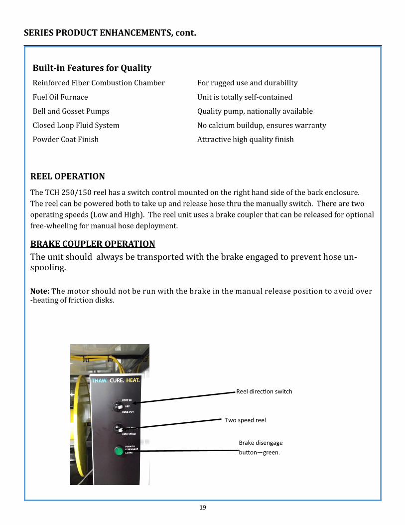
REEL OPERATION
The TCH 250/150 reel has a switch control mounted on the right hand side of the back enclosure.
The reel can be powered both to take up and release hose thru the manually switch. There are two
operating speeds (Low and High). The reel unit uses a brake coupler that can be released for optional
free-wheeling for manual hose deployment.
BRAKE COUPLER OPERATION
The unit should always be transported with the brake engaged to prevent hose un-spooling.
Note: The motor should not be run with the brake in the manual release position to avoid over-heating of friction disks.
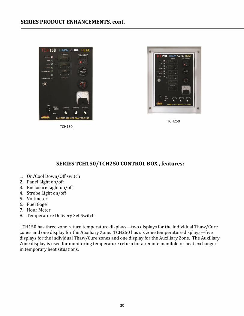
SERIES PRODUCT ENHANCEMENTS, cont.
Brake disengage
button—green.
Two speed reel
Reel direction switch
20
SERIES TCH150/TCH250 CONTROL BOX , features:
1. On/Cool Down/Off switch 2. Panel Light on/off 3. Enclosure Light on/off 4. Strobe Light on/off 5. Voltmeter 6. Fuel Gage 7. Hour Meter 8. Temperature Delivery Set Switch TCH150 has three zone return temperature displays—two displays for the individual Thaw/Cure zones and one display for the Auxiliary Zone. TCH250 has six zone temperature displays—five displays for the individual Thaw/Cure zones and one display for the Auxiliary Zone. The Auxiliary Zone display is used for monitoring temperature return for a remote manifold or heat exchanger in temporary heat situations.
SERIES PRODUCT ENHANCEMENTS, cont.
TCH150
TCH250

21
WATLOW™ OUTPUT TEMPERATURE DELIVERY CONTROL
Press and hold the up or down arrow to select desirable temperature output (temperature range 70° F - 180° F)—The other buttons are disabled. Normal set temperature for Thaw mode is pre-set at 180° F, 82.2° C Ideal Cure mode set temperature is approximately 85° F, 29.4° C Temporary Heat mode can be any set temperature that the environment can endure
SERIES PRODUCT ENHANCEMENTS, cont.

22
23
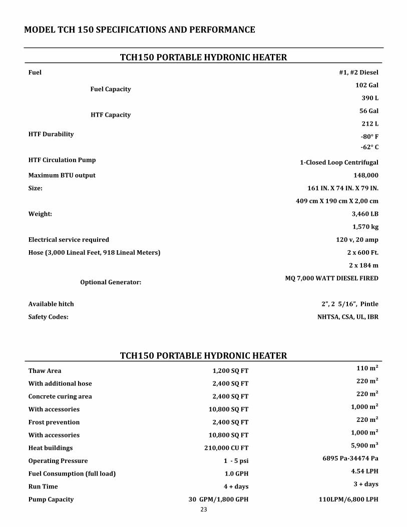
TCH150 PORTABLE HYDRONIC HEATER
Fuel #1, #2 Diesel
Fuel Capacity 102 Gal
390 L
HTF Capacity 56 Gal
212 L
HTF Durability -80° F
-62° C
HTF Circulation Pump 1-Closed Loop Centrifugal
Maximum BTU output 148,000
Size: 161 IN. X 74 IN. X 79 IN.
409 cm X 190 cm X 2,00 cm
Weight: 3,460 LB
1,570 kg
Electrical service required 120 v, 20 amp
Hose (3,000 Lineal Feet, 918 Lineal Meters) 2 x 600 Ft.
2 x 184 m
Optional Generator: MQ 7,000 WATT DIESEL FIRED
Available hitch 2”, 2 5/16”, Pintle
Safety Codes: NHTSA, CSA, UL, IBR
TCH150 PORTABLE HYDRONIC HEATER
Thaw Area 1,200 SQ FT 110 m²
With additional hose 2,400 SQ FT 220 m²
Concrete curing area 2,400 SQ FT 220 m²
With accessories 10,800 SQ FT 1,000 m²
Frost prevention 2,400 SQ FT 220 m²
With accessories 10,800 SQ FT 1,000 m²
Heat buildings 210,000 CU FT 5,900 m³
Operating Pressure 1 - 5 psi 6895 Pa-34474 Pa
Fuel Consumption (full load) 1.0 GPH 4.54 LPH
Run Time 4 + days 3 + days
Pump Capacity 30 GPM/1,800 GPH 110LPM/6,800 LPH
MODEL TCH 150 SPECIFICATIONS AND PERFORMANCE

24
TCH250 PORTABLE HYDRONIC HEATER
Fuel #1, #2 Diesel
Fuel Capacity 160 Gal
608 L
HTF Capacity 122 Gal
464 L
HTF Durability -80° F
-62° C
HTF Circulation Pump 1-Closed Loop Centrifugal
Maximum BTU output 280,000
Size: 170 IN. X 84 IN. X 97 IN.
4,318 mm X 2,133 mm X 2,439 mm
Weight: 5,600 LB
2,522 kg
Electrical service required 120 v, 20 amp
Hose (3,000 Lineal Feet, 918 Lineal Meters) 5 x 600 Ft.
5 x 184 m
Optional Generator: MQ 7,000 WATT DIESEL FIRED
Available hitch 2”, 2 5/16”, Pintle
Safety Codes: NHTSA, CSA, UL, IBR
TCH250 PORTABLE HYDRONIC HEATER
Thaw Area 3,000 SQ FT 278 m²
With additional hose 6,000 SQ FT 550 m²
Concrete curing area 6,000 SQ FT 550 m²
With accessories 18,000 SQ FT 1,670 m²
Frost prevention 9,000 SQ FT 840 m²
With accessories 27,000 SQ FT 2,500 m²
Heat buildings 400,000 CU FT 11,320 m³
Operating Pressure 1 - 5 psi 6895 Pa-34474 Pa
Fuel Consumption (full load) 1.0 GPH 4.54 LPH
Run Time 3 + days 3 + days
Pump Capacity 30 GPM/1,800 GPH 110 PM/6,800 LPH
MODEL TCH 250 SPECIFICATIONS AND PERFORMANCE
25
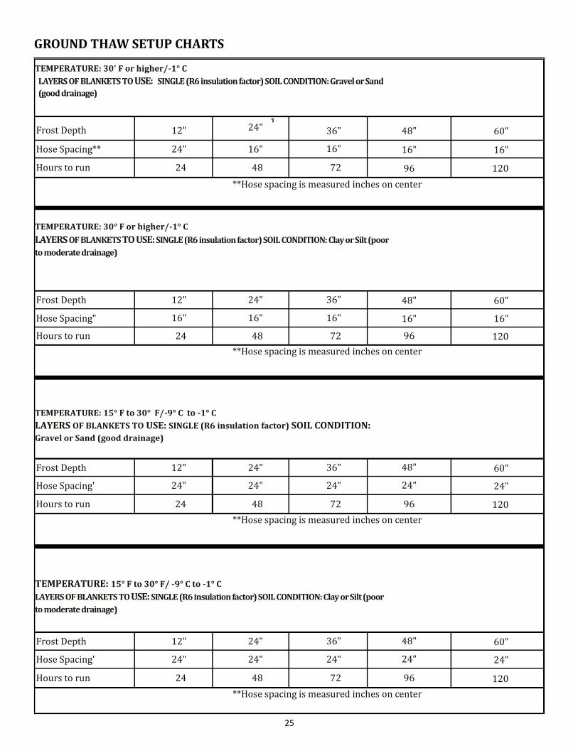
TEMPERATURE: 30' F or higher/-1° C LAYERS OF BLANKETS TO USE: SINGLE (R6 insulation factor) SOIL CONDITION: Gravel or Sand
(good drainage)
Frost Depth 12"
--, 24" 36" 48" 60"
Hose Spacing** 24" 16" 16" 16" 16"
Hours to run 24 48 72 96 120
**Hose spacing is measured inches on center
TEMPERATURE: 30° F or higher/-1° C
LAYERS OF BLANKETS TO USE: SINGLE (R6 insulation factor) SOIL CONDITION: Clay or Silt (poor
to moderate drainage)
Frost Depth 12" 24" 36" 48" 60"
Hose Spacing" 16" 16" 16" 16" 16"
Hours to run 24 48 72 96 120
**Hose spacing is measured inches on center
TEMPERATURE: 15° F to 30° F/-9° C to -1° C LAYERS OF BLANKETS TO USE: SINGLE (R6 insulation factor) SOIL CONDITION: Gravel or Sand (good drainage)
Frost Depth 12" 24" 36" 48" 60"
Hose Spacing' 24" 24" 24" 24" 24"
Hours to run 24 48 72 96 120
**Hose spacing is measured inches on center
TEMPERATURE: 15° F to 30° F/ -9° C to -1° C LAYERS OF BLANKETS TO USE: SINGLE (R6 insulation factor) SOIL CONDITION: Clay or Silt (poor
to moderate drainage)
Frost Depth 12" 24" 36" 48" 60"
Hose Spacing' 24" 24" 24" 24" 24"
Hours to run 24 48 72 96 120
**Hose spacing is measured inches on center
GROUND THAW SETUP CHARTS
26
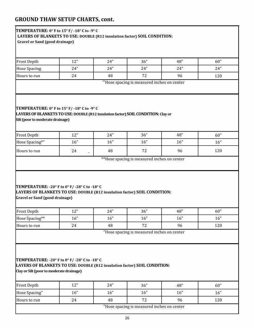
TEMPERATURE: 0° F to 15° F/ -18° C to -9° C LAYERS OF BLANKETS TO USE: DOUBLE (R12 insulation factor) SOIL CONDITION: Gravel or Sand (good drainage)
Frost Depth 12" 24" 36" 48" 60"
Hose Spacing 24" 24" 24" 24" 24"
Hours to run 24 48 72 96 120
'"Hose spacing is measured inches on center
TEMPERATURE: 0° F to 15° F/ -18° C to -9° C LAYERS OF BLANKETS TO USE: DOUBLE (R12 insulation factor) SOIL CONDITION: Clay or
Silt (poor to moderate drainage)
Frost Depth 12" 24" 36" 48" 60"
Hose Spacing*" 16" 16" 16" 16" 16"
Hours to run 24 _ 48 72 96 120
**Hose spacing is measured inches on center
TEMPERATURE: -20° F to 0° F/ -28° C to -18° C LAYERS OF BLANKETS TO USE: DOUBLE (R12 insulation factor) SOIL CONDITION:
Gravel or Sand (good drainage)
Frost Depth 12" 24" 36" 48" 60"
Hose Spacing** 16" 16" 16" 16" 16"
Hours to run 24 48 72 96 120
"Hose spacing is measured inches on center
TEMPERATURE: -20° F to 0° F/ -28° C to -18° C LAYERS OF BLANKETS TO USE: DOUBLE (R12 insulation factor) SOIL CONDITION:
Clay or Silt (poor to moderate drainage)
Frost Depth 12" 24" 36" 48" 60"
Hose Spacing" 16" 16" 16" 16" 16"
Hours to run 24 48 72 96 120
"Hose spacing is measured inches on center
GROUND THAW SETUP CHARTS, cont.
27
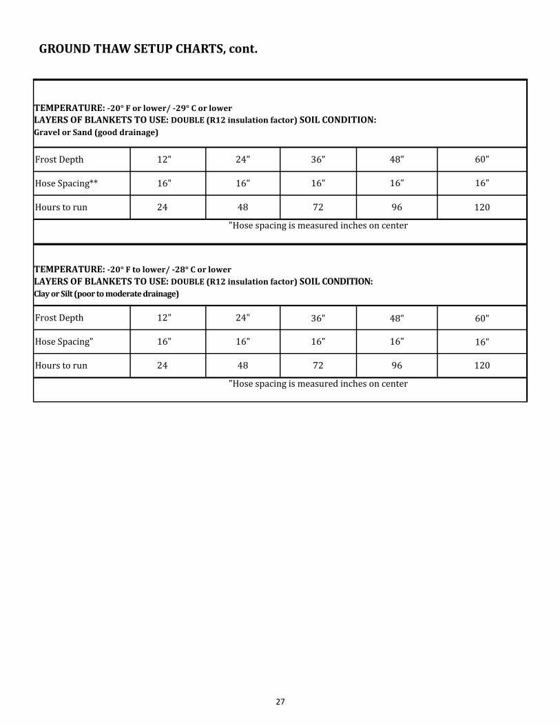
TEMPERATURE: -20° F or lower/ -29° C or lower LAYERS OF BLANKETS TO USE: DOUBLE (R12 insulation factor) SOIL CONDITION:
Gravel or Sand (good drainage)
Frost Depth 12" 24" 36" 48" 60"
Hose Spacing** 16" 16" 16" 16" 16"
Hours to run 24 48 72 96 120
"Hose spacing is measured inches on center
TEMPERATURE: -20° F to lower/ -28° C or lower LAYERS OF BLANKETS TO USE: DOUBLE (R12 insulation factor) SOIL CONDITION:
Clay or Silt (poor to moderate drainage)
Frost Depth 12" 24" 36" 48" 60"
Hose Spacing" 16" 16" 16" 16" 16"
Hours to run 24 48 72 96 120
"Hose spacing is measured inches on center
GROUND THAW SETUP CHARTS, cont.
28
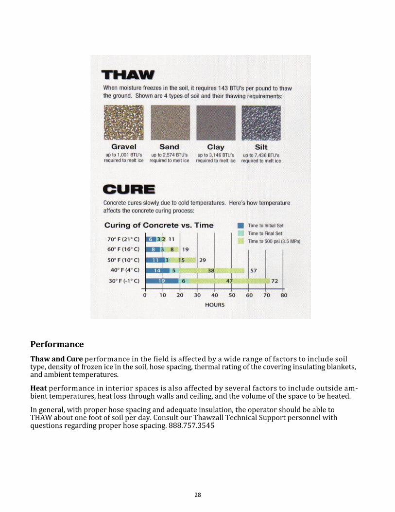
Performance
Thaw and Cure performance in the field is affected by a wide range of factors to include soil type, density of frozen ice in the soil, hose spacing, thermal rating of the covering insulating blankets, and ambient temperatures.
Heat performance in interior spaces is also affected by several factors to include outside am-bient temperatures, heat loss through walls and ceiling, and the volume of the space to be heated.
In general, with proper hose spacing and adequate insulation, the operator should be able to THAW about one foot of soil per day. Consult our Thawzall Technical Support personnel with questions regarding proper hose spacing. 888.757.3545
29
If your Thawzall is to be used at altitudes above 5,000 feet (1,530 meters), the burner nozzle and air intake settings must be changed to accommodate lower oxygen levels at higher altitudes. Please see service bulletin # 501
HOSE CAPACITY FILL CHART
HOSE SIZE GALLONS PER FOOT
(Inside dia.)
1/2 0.016
5/8 0.019
3/4 0.023
1.00 0.04
1 1/4 0.063
HIGH ALTITUDE ADJUSTMENTS
DISCONNECT MAINTENANCE
1. Water and dirt may get into a disconnect piece and cause it to corrode or to work improperly. It is vital
that disconnects be cleaned and lubricated at least once per season or when they get dirty. Failure to
maintain disconnects properly will void the warranty.
To clean disconnects:
Use a mild soap and water or all-purpose cleaner like dish soap or Windex
Use a nylon bristle brush to scrub the couplers. (Do not use a metal brush.)
Rinse and wipe parts dry
Allow parts to dry
To lubricate disconnects:
Use only Silicon based products that do not contain any penetrating oils like LPS or Lubrimatic. Silicone based
lubricants are available at automotive parts stores or farm equipment dealerships.
Apply silicone lubricant liberally.
DO NOT USE WD-40 OR SIMILAR PRODUCTS THAT CONTAIN PENETRATING OIL.
Silicone based lubricants will displace water trapped in the disconnects and will not damage the seals inside.
For repair of the male coupler, please use the following 6 step procedure
1. Place the male coupler in a vise with the valve end up
2. Using a drift punch or other dull or flat tool, push the valve into the coupler body
3. Wedge a steel pick in between the valve and the body to hold the valve down
4. Remove the damaged O-ring and back-up ring with another pick
5. Clean the 0-ring seat and install the back-up ring
6. Lubricate the O-ring seal and install it. Then release the valve by removing the pick
30
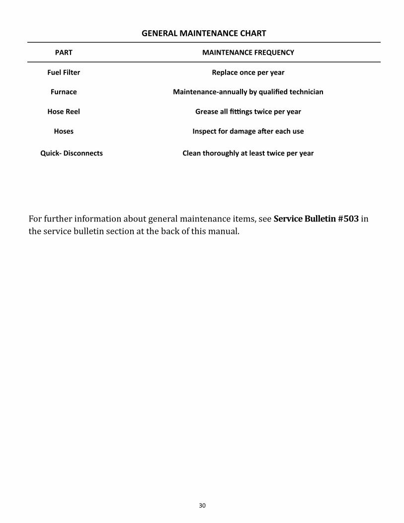
For further information about general maintenance items, see Service Bulletin #503 in
the service bulletin section at the back of this manual.
GENERAL MAINTENANCE CHART
PART MAINTENANCE FREQUENCY
Fuel Filter Replace once per year
Furnace Maintenance-annually by qualified technician
Hose Reel Grease all fittings twice per year
Hoses Inspect for damage after each use
Quick- Disconnects Clean thoroughly at least twice per year
31
Basic Features:
Three indicator lights:
Red reset button/lockout light
Pump Prime
Green flame/recycle light
Limited Reset
Recurring lockouts without a complete heat cycle puts control in restricted (hard lockout) mode
Limited Recycle
If flame is established and then lost, the control will recycle until the cumulative time trial for igni-
tion budget is exhausted and will then go into hard lockout. This prevents excessive oil accumula-
tion in the appliance
Valve on delay—15 seconds Motor-off delay—None
Sequence of Operation
1. Standby 2. Valve-on delay 3. Trial for ignition 4. Lockout 5. Ignition carryover
6. Run 7. Recycle 8. Motor-off delay 9. Pump prime
OPERATING STATES:
STANDBY
The burner is idle, waiting for a call for heat. When a call for heat is initiated, there is a ½ second
delay while the control performs a safe start check
VALVE-ON DELAY (pre-time)
The igniter and motor are on while the oil solenoid valve remains de-energized—typically 15 sec-
onds. Allows the burner to establish air flow and brings the pump to full speed, helping to keep ig-
nitions smooth and clean
TRIAL FOR IGNITION
The oil solenoid valve is energized. A flame should be established within the factory set trial for igni-
tion time (also known as “lockout time”) 15 seconds on the GeniSys control
BECKETT BURNER GENISYS™ CONTROL

32
IGNITION CARRYOVER
Once flame is established, the igniter remains on for 10 additional seconds to ensure flame stability
before shutting off
RUN
The flame is sustained until the call for heat is satisfied or safety limit shuts down burner
MOTOR-OFF DELAY (post-time)
If applicable, the oil solenoid valve is de-energized and the motor continues to run for the preset
motor-off delay time. Cools the nozzle to prevent after drip, and expels fumes and combustion
If the cad cell detects flame in the Motor-Off Delay mode, the control goes into the standby mode.
This is to prevent a failed fuel valve from keeping the flame burning
LOCKOUT—the control has shut down the burner for one of the following safety reasons:
Trial for ignition (lockout) time expires without flame being established
Cad cell detects flame at the end of valve-on delay
Recycle time budget expires
Relay check failure
You can NOT reset the control by interrupting line voltage
RECYCLE
If the flame is lost while the burner is firing, the control shuts down the burner, enters a 60 second
recycle delay, and repeats the ignition sequence. The control will continue to recycle each time the
flame is lost, until it reaches a preset cumulative trial for ignition time allotment. The control will
then go into Hard Lockout instead of recycle. This feature prevents excessive accumulation of oil in
the appliance firing chamber.
PUMP PRIME
Enter Pump Prime mode by holding down the reset button while in the trial for ignition until the
control powers down the equipment. Then oppress the reset button again to enter Pump Prime
mode
The igniter and motor are on 4 minutes, and the cad cell is disregarded. This allows the technician
to prime the pump without having to jumper the cad cell
Terminate the call for heat and the control will exit the pump prime mode and resume normal op-
eration.
You can remove the control from the Pump Prime mode by holding the reset button for 1 second. The
control will return to Standby mode.
OPERATING STATES, cont.:
33
DISABLE FUNCTION
Press and hold red reset button for 1 second at any time to disable the burner
When you release the reset button the burner will return to normal operation
GeniSys control has limited reset
Initial lockouts result in “soft” lockout.
Red light flashing—click the red reset button to restart
Recurring lockouts without completing a heat cycle will result in Restricted (“hard”) lockout.
Red light on steady—hold the red reset button 15 seconds until the yellow light turns on. You
can NOT reset the control by interrupting line voltage.
PUMP PRIME MODE
Prepare the burner for priming
Initiate a call for heat
After the burner starts, press and hold the reset button until the yellow light turns on. (15 sec-
onds)
Release the reset button. The yellow light will turn off and the burner will start again
At burner start up, click the reset button
Enters 4-minute dedicated pump prime mode, with motor and igniter on, and oil valve energized.
The yellow light is on when in the pump prime mode
Terminate the call for heat and the control will exit the pump prime mode and resume normal op-
eration
OPERATING STATES, cont.:
34
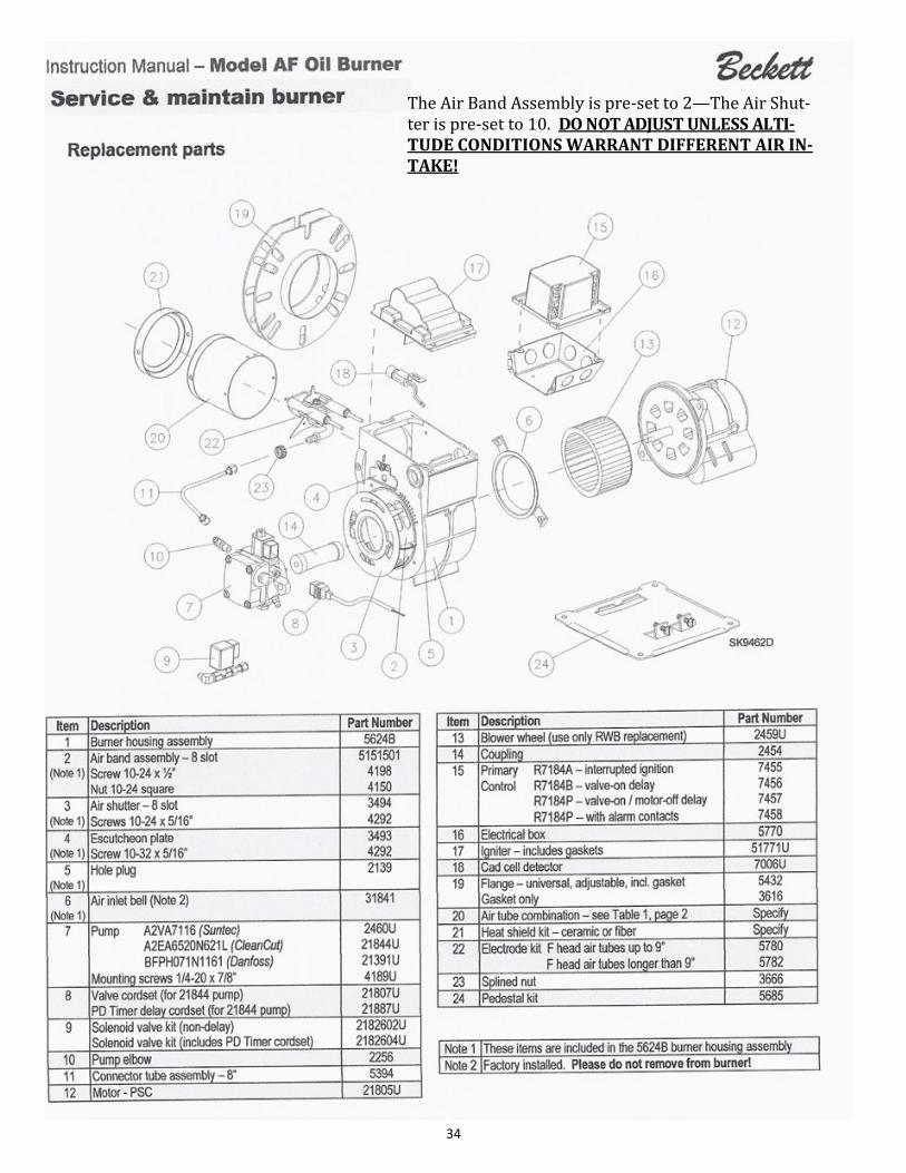
The Air Band Assembly is pre-set to 2—The Air Shut-ter is pre-set to 10. DO NOT ADJUST UNLESS ALTI-TUDE CONDITIONS WARRANT DIFFERENT AIR IN-TAKE!

35
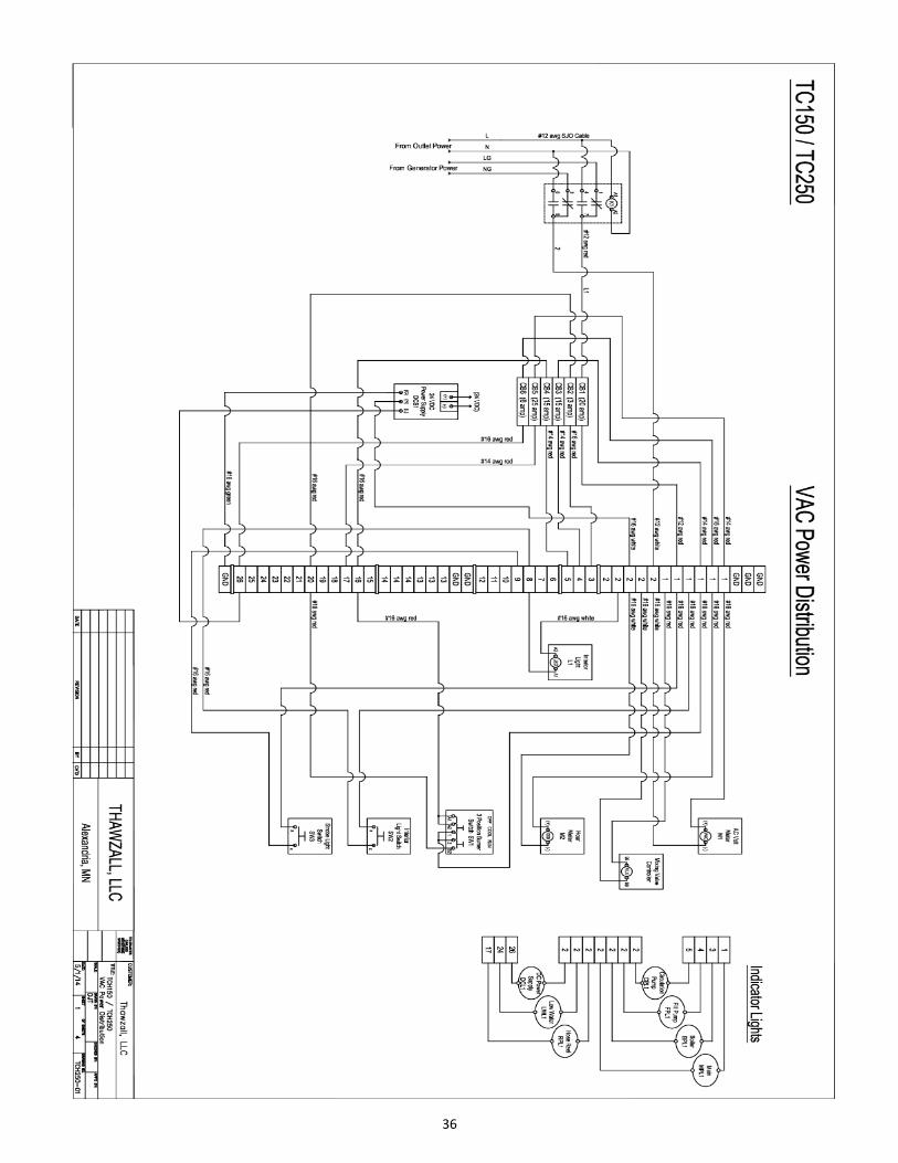
TCH 250 WIRING SCHEMATICS Page 1 - 7
36
37
38
39

40
41
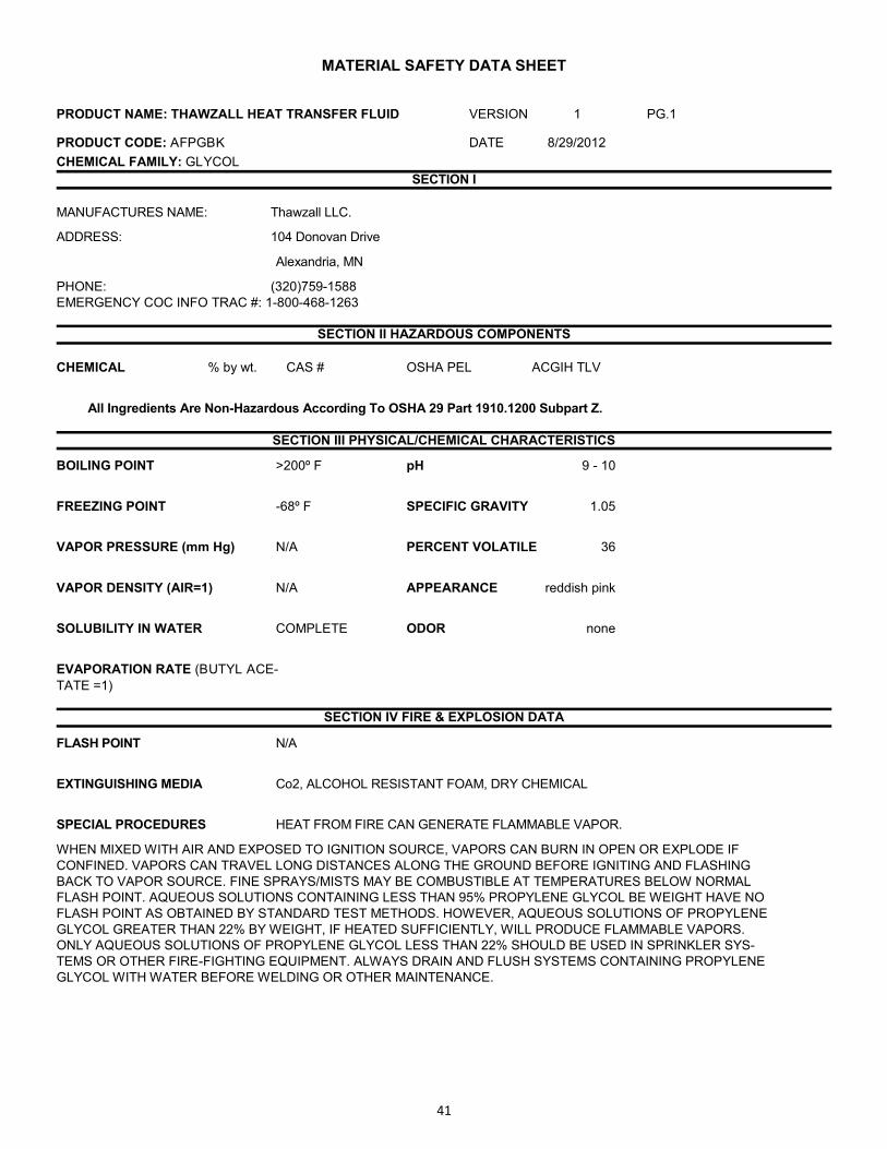
MATERIAL SAFETY DATA SHEET
PRODUCT NAME: THAWZALL HEAT TRANSFER FLUID VERSION 1 PG.1
PRODUCT CODE: AFPGBK DATE 8/29/2012
CHEMICAL FAMILY: GLYCOL
SECTION I
MANUFACTURES NAME: Thawzall LLC.
ADDRESS: 104 Donovan Drive
Alexandria, MN
PHONE: (320)759-1588
EMERGENCY COC INFO TRAC #: 1-800-468-1263
SECTION II HAZARDOUS COMPONENTS
CHEMICAL % by wt. CAS # OSHA PEL ACGIH TLV
All Ingredients Are Non-Hazardous According To OSHA 29 Part 1910.1200 Subpart Z.
SECTION III PHYSICAL/CHEMICAL CHARACTERISTICS
BOILING POINT >200º F pH 9 - 10
FREEZING POINT -68º F SPECIFIC GRAVITY 1.05
VAPOR PRESSURE (mm Hg) N/A PERCENT VOLATILE 36
VAPOR DENSITY (AIR=1) N/A APPEARANCE reddish pink
SOLUBILITY IN WATER COMPLETE ODOR none
EVAPORATION RATE (BUTYL ACE-
TATE =1)
SECTION IV FIRE & EXPLOSION DATA
FLASH POINT N/A
EXTINGUISHING MEDIA Co2, ALCOHOL RESISTANT FOAM, DRY CHEMICAL
SPECIAL PROCEDURES HEAT FROM FIRE CAN GENERATE FLAMMABLE VAPOR.
WHEN MIXED WITH AIR AND EXPOSED TO IGNITION SOURCE, VAPORS CAN BURN IN OPEN OR EXPLODE IF
CONFINED. VAPORS CAN TRAVEL LONG DISTANCES ALONG THE GROUND BEFORE IGNITING AND FLASHING
BACK TO VAPOR SOURCE. FINE SPRAYS/MISTS MAY BE COMBUSTIBLE AT TEMPERATURES BELOW NORMAL
FLASH POINT. AQUEOUS SOLUTIONS CONTAINING LESS THAN 95% PROPYLENE GLYCOL BE WEIGHT HAVE NO
FLASH POINT AS OBTAINED BY STANDARD TEST METHODS. HOWEVER, AQUEOUS SOLUTIONS OF PROPYLENE
GLYCOL GREATER THAN 22% BY WEIGHT, IF HEATED SUFFICIENTLY, WILL PRODUCE FLAMMABLE VAPORS.
ONLY AQUEOUS SOLUTIONS OF PROPYLENE GLYCOL LESS THAN 22% SHOULD BE USED IN SPRINKLER SYS-
TEMS OR OTHER FIRE-FIGHTING EQUIPMENT. ALWAYS DRAIN AND FLUSH SYSTEMS CONTAINING PROPYLENE
GLYCOL WITH WATER BEFORE WELDING OR OTHER MAINTENANCE.
42
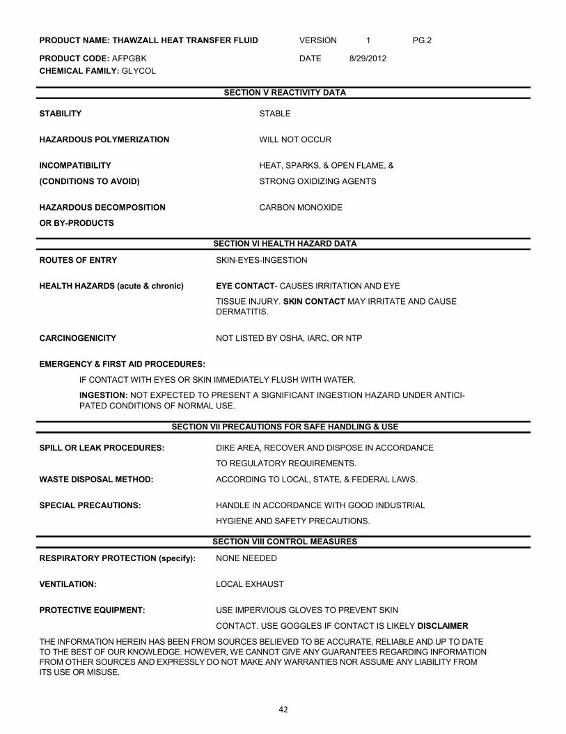
PRODUCT NAME: THAWZALL HEAT TRANSFER FLUID VERSION 1 PG.2
PRODUCT CODE: AFPGBK DATE 8/29/2012
CHEMICAL FAMILY: GLYCOL
SECTION V REACTIVITY DATA
STABILITY STABLE
HAZARDOUS POLYMERIZATION WILL NOT OCCUR
INCOMPATIBILITY HEAT, SPARKS, & OPEN FLAME, &
(CONDITIONS TO AVOID) STRONG OXIDIZING AGENTS
HAZARDOUS DECOMPOSITION CARBON MONOXIDE
OR BY-PRODUCTS
SECTION VI HEALTH HAZARD DATA
ROUTES OF ENTRY SKIN-EYES-INGESTION
HEALTH HAZARDS (acute & chronic) EYE CONTACT- CAUSES IRRITATION AND EYE
TISSUE INJURY. SKIN CONTACT MAY IRRITATE AND CAUSE
DERMATITIS.
CARCINOGENICITY NOT LISTED BY OSHA, IARC, OR NTP
EMERGENCY & FIRST AID PROCEDURES:
IF CONTACT WITH EYES OR SKIN IMMEDIATELY FLUSH WITH WATER.
INGESTION: NOT EXPECTED TO PRESENT A SIGNIFICANT INGESTION HAZARD UNDER ANTICI-
PATED CONDITIONS OF NORMAL USE.
SECTION VII PRECAUTIONS FOR SAFE HANDLING & USE
SPILL OR LEAK PROCEDURES: DIKE AREA, RECOVER AND DISPOSE IN ACCORDANCE
TO REGULATORY REQUIREMENTS.
WASTE DISPOSAL METHOD: ACCORDING TO LOCAL, STATE, & FEDERAL LAWS.
SPECIAL PRECAUTIONS: HANDLE IN ACCORDANCE WITH GOOD INDUSTRIAL
HYGIENE AND SAFETY PRECAUTIONS.
SECTION VIII CONTROL MEASURES
RESPIRATORY PROTECTION (specify): NONE NEEDED
VENTILATION: LOCAL EXHAUST
PROTECTIVE EQUIPMENT: USE IMPERVIOUS GLOVES TO PREVENT SKIN
CONTACT. USE GOGGLES IF CONTACT IS LIKELY DISCLAIMER
THE INFORMATION HEREIN HAS BEEN FROM SOURCES BELIEVED TO BE ACCURATE, RELIABLE AND UP TO DATE
TO THE BEST OF OUR KNOWLEDGE. HOWEVER, WE CANNOT GIVE ANY GUARANTEES REGARDING INFORMATION
FROM OTHER SOURCES AND EXPRESSLY DO NOT MAKE ANY WARRANTIES NOR ASSUME ANY LIABILITY FROM
ITS USE OR MISUSE.
43
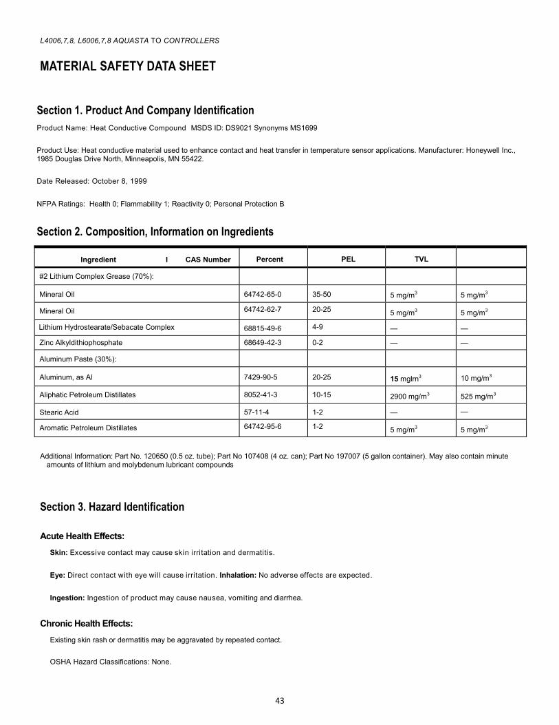
L4006,7,8, L6006,7,8 AQUASTA TO CONTROLLERS
MATERIAL SAFETY DATA SHEET
Section 1. Product And Company Identification
Product Name: Heat Conductive Compound MSDS ID: DS9021 Synonyms MS1699
Product Use: Heat conductive material used to enhance contact and heat transfer in temperature sensor applications. Manufacturer: Honeywell Inc., 1985 Douglas Drive North, Minneapolis, MN 55422.
Date Released: October 8, 1999
NFPA Ratings: Health 0; Flammability 1; Reactivity 0; Personal Protection B
Section 2. Composition, Information on Ingredients
Additional Information: Part No. 120650 (0.5 oz. tube); Part No 107408 (4 oz. can); Part No 197007 (5 gallon container). May also contain minute
amounts of lithium and molybdenum lubricant compounds
Section 3. Hazard Identification
Acute Health Effects:
Skin: Excessive contact may cause skin irritation and dermatitis.
Eye: Direct contact with eye will cause irritation. Inhalation: No adverse effects are expected.
Ingestion: Ingestion of product may cause nausea, vomiting and diarrhea.
Chronic Health Effects:
Existing skin rash or dermatitis may be aggravated by repeated contact.
OSHA Hazard Classifications: None.
Ingredient I CAS Number Percent PEL TVL
#2 Lithium Complex Grease (70%):
Mineral Oil 64742-65-0 35-50 5 mg/m3 5 mg/m3
Mineral Oil 64742-62-7 20-25 5 mg/m3 5 mg/m3
Lithium Hydrostearate/Sebacate Complex 68815-49-6 4-9 — —
Zinc Alkyldithiophosphate 68649-42-3 0-2 — —
Aluminum Paste (30%):
Aluminum, as Al 7429-90-5 20-25 15 mglrn3 10 mg/m3
Aliphatic Petroleum Distillates 8052-41-3 10-15 2900 mg/m3 525 mg/m3
Stearic Acid 57-11-4 1-2 — —
Aromatic Petroleum Distillates 64742-95-6 1-2 5 mg/m3 5 mg/m3
44
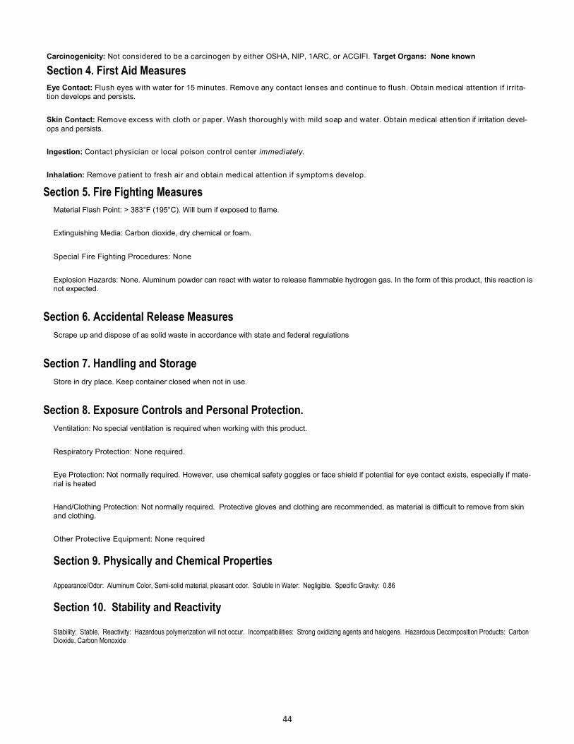
Carcinogenicity: Not considered to be a carcinogen by either OSHA, NIP, 1ARC, or ACGIFI. Target Organs: None known
Section 4. First Aid Measures
Eye Contact: Flush eyes with water for 15 minutes. Remove any contact lenses and continue to flush. Obtain medical attention if irrita-
tion develops and persists.
Skin Contact: Remove excess with cloth or paper. Wash thoroughly with mild soap and water. Obtain medical atten tion if irritation devel-
ops and persists.
Ingestion: Contact physician or local poison control center immediately.
Inhalation: Remove patient to fresh air and obtain medical attention if symptoms develop.
Section 5. Fire Fighting Measures
Material Flash Point: > 383°F (195°C). Will burn if exposed to flame.
Extinguishing Media: Carbon dioxide, dry chemical or foam.
Special Fire Fighting Procedures: None
Explosion Hazards: None. Aluminum powder can react with water to release flammable hydrogen gas. In the form of this product, this reaction is not expected.
Section 6. Accidental Release Measures
Scrape up and dispose of as solid waste in accordance with state and federal regulations
Section 7. Handling and Storage
Store in dry place. Keep container closed when not in use.
Section 8. Exposure Controls and Personal Protection.
Ventilation: No special ventilation is required when working with this product.
Respiratory Protection: None required.
Eye Protection: Not normally required. However, use chemical safety goggles or face shield if potential for eye contact exists, especially if mate-
rial is heated
Hand/Clothing Protection: Not normally required. Protective gloves and clothing are recommended, as material is difficult to remove from skin
and clothing.
Other Protective Equipment: None required
Section 9. Physically and Chemical Properties
Appearance/Odor: Aluminum Color, Semi-solid material, pleasant odor. Soluble in Water: Negligible. Specific Gravity: 0.86
Section 10. Stability and Reactivity
Stability: Stable. Reactivity: Hazardous polymerization will not occur. Incompatibilities: Strong oxidizing agents and halogens. Hazardous Decomposition Products: Carbon Dioxide, Carbon Monoxide
45
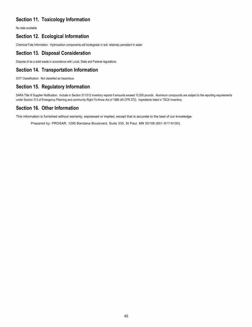
Section 11. Toxicology Information
No date available
Section 12. Ecological Information
Chemical Fate Information: Hydrocarbon components will biodegrade in soil; relatively persistent in water
Section 13. Disposal Consideration
Dispose of as a solid waste in accordance with Local, State and Federal regulations.
Section 14. Transportation Information
DOT Classification: Not classified as hazardous.
Section 15. Regulatory Information
SARA Title III Supplier Notification: Include in Section 311/312 inventory reports if amounts exceed 10,000 pounds. Aluminum compounds are subject to the reporting requirements
under Section 313 of Emergency Planning and community Right-To-Know Act of 1986 (40 CFR 372). Ingredients listed in TSCA Inventory.
Section 16. Other Information
This information is furnished without warranty, expressed or implied, except that is accurate to the best of our knowledge.
Prepared by: PROSAR, 1295 Bandana Boulevard, Suite 335, St Paul, MN 55108 (651-917-6100).

46
47
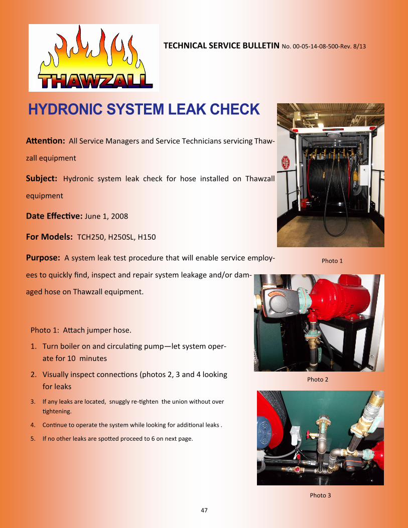
TECHNICAL SERVICE BULLETIN No. 00-05-14-08-500-Rev. 8/13
Attention: All Service Managers and Service Technicians servicing Thaw
zall equipment
Subject: Hydronic system leak check for hose installed on Thawzall
equipment
Date Effective: June 1, 2008
For Models: TCH250, H250SL, H150
Purpose: A system leak test procedure that will enable service employ
ees to quickly find, inspect and repair system leakage and/or dam
aged hose on Thawzall equipment.
Photo 1
Photo 2
Photo 3
Photo 1: Attach jumper hose.
1. Turn boiler on and circulating pump—let system oper
ate for 10 minutes
2. Visually inspect connections (photos 2, 3 and 4 looking
for leaks
3. If any leaks are located, snuggly re-tighten the union without over
tightening.
4. Continue to operate the system while looking for additional leaks .
5. If no other leaks are spotted proceed to 6 on next page.
48
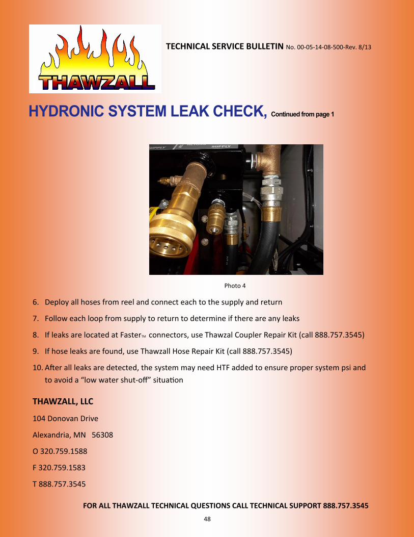
TECHNICAL SERVICE BULLETIN No. 00-05-14-08-500-Rev. 8/13
Photo 4
6. Deploy all hoses from reel and connect each to the supply and return
7. Follow each loop from supply to return to determine if there are any leaks
8. If leaks are located at FasterTM connectors, use Thawzal Coupler Repair Kit (call 888.757.3545)
9. If hose leaks are found, use Thawzall Hose Repair Kit (call 888.757.3545)
10. After all leaks are detected, the system may need HTF added to ensure proper system psi and
to avoid a “low water shut-off” situation
THAWZALL, LLC
104 Donovan Drive
Alexandria, MN 56308
O 320.759.1588
F 320.759.1583
T 888.757.3545
FOR ALL THAWZALL TECHNICAL QUESTIONS CALL TECHNICAL SUPPORT 888.757.3545
49
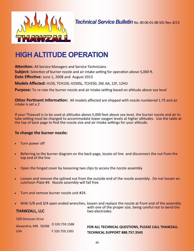
No. 00-06-01-08-501 Rev. 8/13
Attention: All Service Managers and Service Technicians
Subject: Selection of burner nozzle and air intake setting for operation above 5,000 ft.
Date Effective: June 1, 2008 and August 2013
Models Affected: H150, TCH150, H250SL, TCH250, 2M, 6A, 12F, 12HU
Purpose: To re-rate the burner nozzle and air intake setting based on altitude above sea level
Other Pertinent Information: All models affected are shipped with nozzle numbered 1.75 and air intake is set a 2
If your Thawzall is to be used at altitudes above 5,000 feet above sea level, the burner nozzle and air intake setting must be changed to accommodate lower oxygen levels at higher altitudes. Use the table at the top of back page to find the nozzle size and air intake settings for your altitude.
To change the burner nozzle:
Turn power off
Referring to the burner diagram on the back page, locate oil line and disconnect the nut from the top end of the line
Open the hinged cover by loosening two clips to access the nozzle assembly
Loosen and remove the splined nut from the outside end of the nozzle assembly. Do not loosen escutcheon Plate #4. Nozzle assembly will fall free.
Turn and remove burner nozzle unit #24.
With 5/8 and 3/4 open ended wrenches, loosen and replace the nozzle at front end of the assembly with one of the proper size, being careful not to bend the two electrodes. THAWZALL, LLC
104 Donovan Drive
Alexandria, MN 56308
USA
O 320.759.1588
F 320.759.1583 FOR ALL TECHNICAL QUESTIONS, PLEASE CALL THAWZALL
TECHNICAL SUPPORT 888.757.3545
50
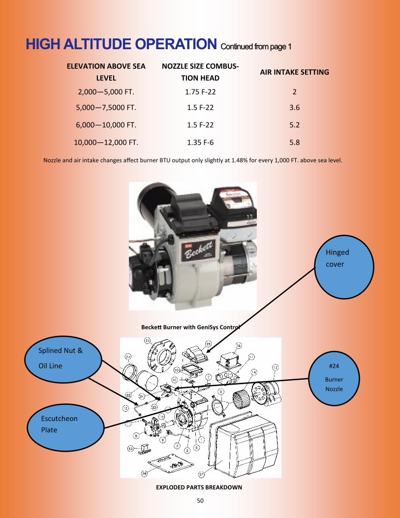
ELEVATION ABOVE SEA
LEVEL
NOZZLE SIZE COMBUS-
TION HEAD AIR INTAKE SETTING
2,000—5,000 FT. 1.75 F-22 2
5,000—7,5000 FT. 1.5 F-22 3.6
6,000—10,000 FT. 1.5 F-22 5.2
10,000—12,000 FT. 1.35 F-6 5.8
Splined Nut &
Oil Line
Beckett Burner with GeniSys Control
Nozzle and air intake changes affect burner BTU output only slightly at 1.48% for every 1,000 FT. above sea level.
Hinged
cover
Escutcheon
Plate
EXPLODED PARTS BREAKDOWN
#24
Burner
Nozzle
51
Attention: Service Managers and Service Technicians
Subject: Testing of Heat Transfer Fluid (HTF) for freeze protection
Date Effective: June 1, 2008 (rev. 8/13)
Models Affected:
TCH 250, H250SL, H150, 2M, 6A, 12HU, 12F, XH, and all new HEATZONE™ Series machines.
Purpose:
To ensure that the heat transfer fluid in the Thawzall system is concentrated enough to re-sist freezing in cold weather., all Thawzall model systems are now shipped with full strength (not diluted with water) Thawzall Heat Transfer Fluid. Full strength HTF provides freeze protection down to -70° F or -56° C. HTF is not automotive antifreeze.
Automotive antifreeze MUST NOT be used in your Thawzall. Please follow this three step procedure:
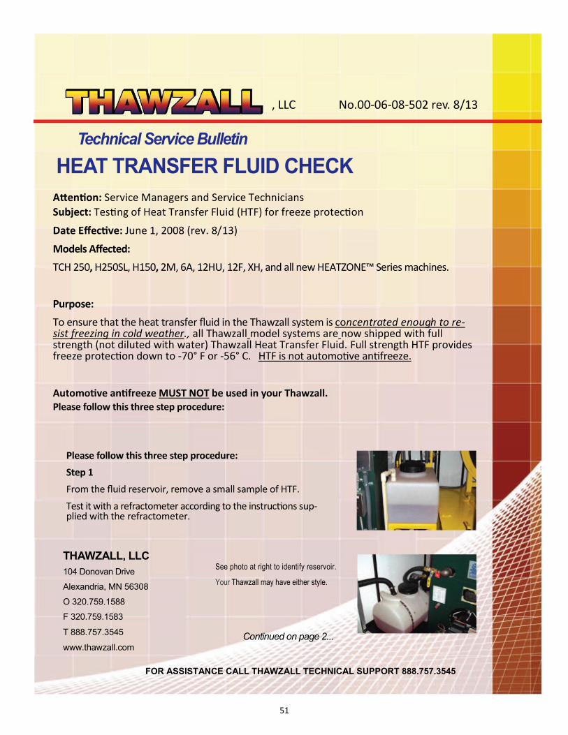
See photo at right to identify reservoir.
Your Thawzall may have either style.
Please follow this three step procedure:
Step 1
From the fluid reservoir, remove a small sample of HTF.
Test it with a refractometer according to the instructions supplied with the refractometer.
Continued on page 2...
THAWZALL, LLC
104 Donovan Drive
Alexandria, MN 56308
O 320.759.1588
F 320.759.1583
T 888.757.3545
www.thawzall.com
, LLC No.00-06-08-502 rev. 8/13
FOR ASSISTANCE CALL THAWZALL TECHNICAL SUPPORT 888.757.3545
52
No.00-06-08-502 rev. 8/13
...continued from Page 1
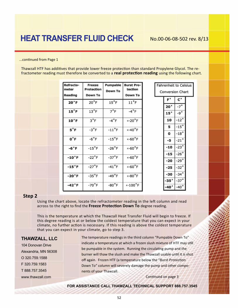
Thawzall HTF has additives that provide lower freeze protection than standard Propylene Glycol. The refractometer reading must therefore be converted to a real protection reading using the following chart.
Step 2 Using the chart above, locate the refractometer reading in the left column and read across to the right to find the Freeze Protection Down To degree reading. This is the temperature at which the Thawzall Heat Transfer Fluid will begin to freeze. If this degree reading is at or below the coldest temperature that you can expect in your climate, no further action is necessary. If this reading is above the coldest temperature that you can expect in your climate, go to step 3.
THAWZALL, LLC
104 Donovan Drive
Alexandria, MN 56308
O 320.759.1588
F 320.759.1583
T 888.757.3545
www.thawzall.com
The temperature readings in the third column “Pumpable Down To”
indicate a temperature at which a frozen slush mixture of HTF may still
be pumpable in the system. Running the circulating pump and the
burner will thaw the slush and make the Thawzall usable until it is shut
off again. Frozen HTF (a temperature below the “Burst Protection
Down To” column will severely damage the pump and other compo
nents of your Thawzall.
Continued on page 3
FOR ASSISTANCE CALL THAWZALL TECHNICAL SUPPORT 888.757.3545
53
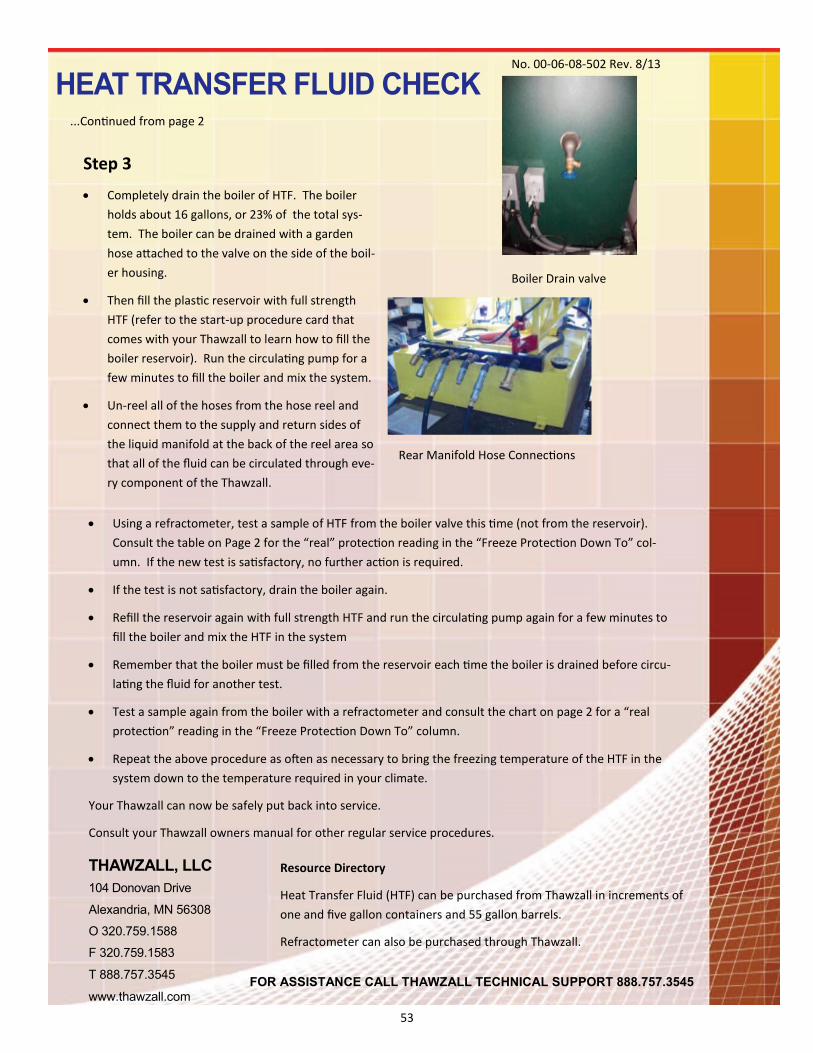
Boiler Drain valve
Rear Manifold Hose Connections
No. 00-06-08-502 Rev. 8/13
...Continued from page 2
Step 3
Completely drain the boiler of HTF. The boiler
holds about 16 gallons, or 23% of the total sys
tem. The boiler can be drained with a garden
hose attached to the valve on the side of the boil
er housing.
Then fill the plastic reservoir with full strength
HTF (refer to the start-up procedure card that
comes with your Thawzall to learn how to fill the
boiler reservoir). Run the circulating pump for a
few minutes to fill the boiler and mix the system.
Un-reel all of the hoses from the hose reel and
connect them to the supply and return sides of
the liquid manifold at the back of the reel area so
that all of the fluid can be circulated through eve
ry component of the Thawzall.
Using a refractometer, test a sample of HTF from the boiler valve this time (not from the reservoir).
Consult the table on Page 2 for the “real” protection reading in the “Freeze Protection Down To” col
umn. If the new test is satisfactory, no further action is required.
If the test is not satisfactory, drain the boiler again.
Refill the reservoir again with full strength HTF and run the circulating pump again for a few minutes to
fill the boiler and mix the HTF in the system
Remember that the boiler must be filled from the reservoir each time the boiler is drained before circu
lating the fluid for another test.
Test a sample again from the boiler with a refractometer and consult the chart on page 2 for a “real
protection” reading in the “Freeze Protection Down To” column.
Repeat the above procedure as often as necessary to bring the freezing temperature of the HTF in the
system down to the temperature required in your climate.
Your Thawzall can now be safely put back into service.
Consult your Thawzall owners manual for other regular service procedures.
THAWZALL, LLC
104 Donovan Drive
Alexandria, MN 56308
O 320.759.1588
F 320.759.1583
T 888.757.3545
www.thawzall.com
Resource Directory
Heat Transfer Fluid (HTF) can be purchased from Thawzall in increments of
one and five gallon containers and 55 gallon barrels.
Refractometer can also be purchased through Thawzall.
FOR ASSISTANCE CALL THAWZALL TECHNICAL SUPPORT 888.757.3545

54
55
, LLC No. 00-07-20-08-503 Rev. 8/13
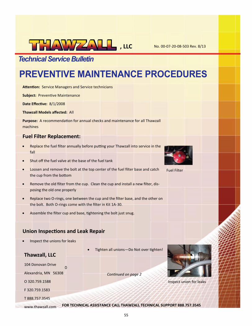
Fuel Filter
Inspect union for leaks
Attention: Service Managers and Service technicians
Subject: Preventive Maintenance
Date Effective: 8/1/2008
Thawzall Models affected: All
Purpose: A recommendation for annual checks and maintenance for all Thawzall
machines
Fuel Filter Replacement:
Replace the fuel filter annually before putting your Thawzall into service in the
fall
Shut off the fuel valve at the base of the fuel tank
Loosen and remove the bolt at the top center of the fuel filter base and catch
the cup from the bottom
Remove the old filter from the cup. Clean the cup and install a new filter, dis
posing the old one properly
Replace two O-rings, one between the cup and the filter base, and the other on
the bolt. Both O-rings come with the filter in Kit 1A-30.
Assemble the filter cup and base, tightening the bolt just snug.
Union Inspections and Leak Repair
Inspect the unions for leaks
Tighten all unions—Do Not over tighten!
Thawzall, LLC
104 Donovan Drive
Alexandria, MN 56308
O 320.759.1588
F 320.759.1583
T 888.757.3545
www.thawzall.com
Continued on page 2
FOR TECHNICAL ASSISTANCE CALL THAWZALL TECHNICAL SUPPORT 888.757.3545
56
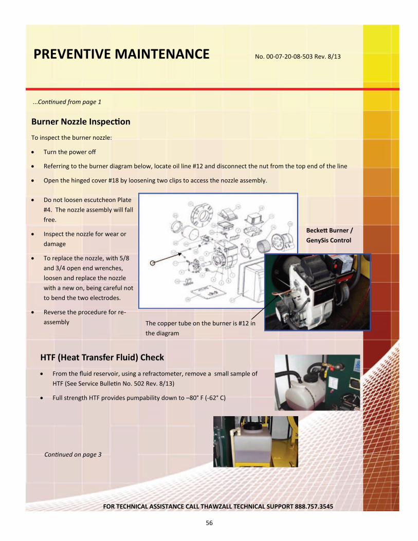
PREVENTIVE MAINTENANCE No. 00-07-20-08-503 Rev. 8/13
...Continued from page 1
Burner Nozzle Inspection
To inspect the burner nozzle:
Turn the power off
Referring to the burner diagram below, locate oil line #12 and disconnect the nut from the top end of the line
Open the hinged cover #18 by loosening two clips to access the nozzle assembly.
Do not loosen escutcheon Plate
#4. The nozzle assembly will fall
free.
Inspect the nozzle for wear or
damage
To replace the nozzle, with 5/8
and 3/4 open end wrenches,
loosen and replace the nozzle
with a new on, being careful not
to bend the two electrodes.
Reverse the procedure for re-
assembly
Beckett Burner /
GenySis Control
The copper tube on the burner is #12 in
the diagram
HTF (Heat Transfer Fluid) Check
From the fluid reservoir, using a refractometer, remove a small sample of
HTF (See Service Bulletin No. 502 Rev. 8/13)
Full strength HTF provides pumpability down to –80° F (-62° C)
Continued on page 3
FOR TECHNICAL ASSISTANCE CALL THAWZALL TECHNICAL SUPPORT 888.757.3545
57
PREVENTIVE MAINTENANCE No. 00-07-20-08-503 Rev. 8/13
...Continued from page 3
Visual Inspection of Burner, Boiler and Chimney
Visually inspect the chimney for signs of soot or damage to the chimney and cap. Excessive soot
means that the burner is not combusting cleanly and may not be properly adjusted. (see Tech
nical Service Bulletin 00-06-01-08-501 Rev. 8/13 for proper settings)
Open the Columbia burner inspection door and inspect the inside of the boiler with a flashlight.
Note evidence of excessive sooting or any apparent cracks. If any evidence is found, call Thaw
zall Technical Support at 888.757.3545.
Resource Directory
Fuel Filter Kit Item No. 1A-30
Full Synthetic 75-90 Gear Oil made by Valvoline and other oil suppliers
HTF—Available in 1 and 5 gallon containers or 55 gallon drums from Thawzall, LLC.
Always use
Thawzall approved HTF to avoid warranty denial.
Thawzall, LLC
104 Donovan Drive
Alexandria, MN 56308
O 320.759.1588
F 320.759.1583
T 888.757.3545
www.thawzall.com
FOR TECHNICAL ASSISTANCE CALL THAWZALL TECHNICAL SUPPORT 888.757.3545

58
59
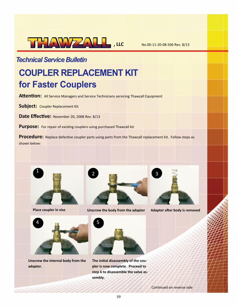
, LLC No.00-11-20-08-506 Rev. 8/13
1
Attention: All Service Managers and Service Technicians servicing Thawzall Equipment
Subject: Coupler Replacement Kit
Date Effective: November 20, 2008 Rev. 8/13
Purpose: For repair of existing couplers using purchased Thawzall kit
Procedure: Replace defective coupler parts using parts from the Thawzall replacement kit. Follow steps as
shown below:
2 3
4 5
Place coupler in vise Unscrew the body from the adaptor Adaptor after body is removed
Unscrew the internal body from the
adaptor.
The initial disassembly of the cou-
pler is now complete. Proceed to
step 6 to disassemble the valve as-
sembly.
Continued on reverse side
60
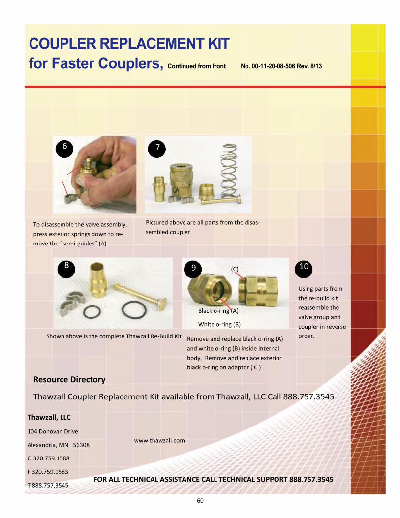
6 7
8 9 10
Using parts from
the re-build kit
reassemble the
valve group and
coupler in reverse
order.
(C)
Black o-ring (A)
White o-ring (B)
Shown above is the complete Thawzall Re-Build Kit
Pictured above are all parts from the disas
sembled coupler To disassemble the valve assembly,
press exterior springs down to re
move the “semi-guides” (A)
Remove and replace black o-ring (A)
and white o-ring (B) inside internal
body. Remove and replace exterior
black o-ring on adaptor ( C )
Resource Directory
Thawzall Coupler Replacement Kit available from Thawzall, LLC Call 888.757.3545
Thawzall, LLC
104 Donovan Drive
Alexandria, MN 56308
O 320.759.1588
F 320.759.1583
T 888.757.3545
www.thawzall.com
FOR ALL TECHNICAL ASSISTANCE CALL TECHNICAL SUPPORT 888.757.3545
61
LIMITED WARRANTY
GENERAL:
THAWZALL, LLC hereby extends to the original purchaser of its THAWZALL (“Ground Defrosting, Thawing, Temporary Heat or
Concrete Curing Products”) a warranty against defects in materials and workmanship for a two year time period as indicated below.
The warranty is only valid on “Ground Defrosting, Thawing, Temporary Heat or Concrete Curing Products” purchased and used in
accordance with placards and instructions (e.g. Operators Manuals) provided by Thawzall, LLC. This warranty applies only to the
original purchaser and is subject to the terms and conditions set forth below.
THAWZALL, LLC will repair or replace (at its discretion) a ground defrosting, thawing, temporary heat or concrete curing product
(or component thereof) if it fails to conform to this warranty. In the event a ground defrosting, thawing, temporary heat or concrete
curing product is to be repaired pursuant to this warranty, such repair work will be performed by THAWZALL, LLC or at its direc-
tion.
WARRANTY PERIOD:
The warranty relating to workmanship, materials and labor on THAWZALL ground defrosting, temporary heat or concrete cur-
ing products extends for two (2) years from the date of original invoice.
WARRANTY POLICY:
When claiming warranty, you must give Thawzall the VIN number of the machine and date of invoice or original invoice
number of the machine or part and Thawzall will determine if the affected machine and part is within the warranty period:
To Start a claim, go to our website and complete a warranty claim and e-mail to [email protected]
Thawzall will issue an RMA # for the defective part and provide a pre-paid freight return tag or call tag issued
through UPS. If the part(s) is not returned within 30 days from the RMA date, you will no longer be eligible
for any credit towards the replacement part.
You will need to issue a PO for the replacement part and Thawzall will invoice you for the replacement part and freight.
Once Thawzall receives the defective part we will inspect and test the part or have our vendor inspect it. If
the part is determined to be defective a credit will be issued for only the part cost. If it is determined that the part is
NOT defective, you will be a charged for the time it took to inspect and test the part (Labor rate of $100.00 per
hour).
WARRANTY PROCEDURE:
RMA – (Return Material Authorization): To ensure processing of warranty claim, a Return Merchandise Authorization (“RA”) must
be obtained at the time of claim and prominently shown on correspondence and packages. To obtain warranty and an RMA, call
888.757.3545 (U.S. Central Time) or E-mail [email protected]. Parts must be returned within 30 days of an RMA being is-
sued to receive credit.
62
WARRANTY LIMITATIONS:
Thawzall Ground Defrosting, Thawing, Temporary Heat or Concrete Curing products must be installed (where appli-
cable), operated and maintained in accordance with all instructions provided by Thawzall, LLC. Failure to follow our
installation (where applicable), operating or maintenance procedures and/or use of unauthorized parts may void this
warranty.
Purchasers and Users are responsible for the suitability of the products for their application.
This warranty does not apply to:
Repairs or replacements necessitated by any cause beyond the control of THAWZALL, LLC including, but
not limited to, any malfunction, defect or failure caused by or resulting from unauthorized service
or parts; installation (where applicable), operating or maintenance contrary to furnished instruc-
tions; local water conditions, handling, shipping or transit accidents; modifications or repair by the
user; abuse; misuse; neglect; accident; incorrect power line voltage; power line surge; lightning
damage; or fire, flood, or other Acts of God.
Repair or replacement in the ordinary course of expendable ground defrosting, thawing, temporary heat or
concrete curing product part.
Elements and controls whose damage or failure is attributable to corrosion, scale, or dirt accumulations or
to low water conditions.
Thawzall, LLC is not liable for labor and other costs incurred in removal, reinstallation, or unauthorized repair
of the Ground Defrosting, Thawing, Temporary Heat or Concrete Curing product or for damages of any type
whatsoever including incidental or consequential damages.
There are no warranties which extend beyond the description contained herein and specifically liability for any breach
of any implied warranty of merchantability or fitness for a purpose is excluded. The duration of any warranties which
may be implied by law notwithstanding the previous sentence (including the warranties of merchantability and fitness)
is limited to the term of this warranty. In no event shall Thawzall, LLC be liable for special, incidental or consequential
damages arising from ownership or use of any Ground Defrosting, Thawing, Temporary Heat, or Concrete Curing
product, or for any delay in the performance of it obligations under this warranty due to causes beyond its control.
Some states do not allow limitations on how long an implied warranty lasts and/or do not allow the exclusion or limita-
tion of consequential damages, so the above limitations and exclusion may not apply to you. This warranty gives you
specific legal rights. You may have other rights, which vary from state to state.
This warranty set forth herein is in lieu of all other expressed or implied warranties. THAWZALL, LLC does not as-
sume or authorize any party to assume for it any other obligation or liability.
THAWZALL, LLC
104 Donovan Drive
PO Box 158
Alexandria, MN 56308 USA
TF 888.757.3545
T 320.759.1588
F 320.634.4563
Email: [email protected]
Website: www.thawzall.com
63
How to File a Warranty Claim
The warranty on your Thawzall covers parts and labor for two years from the date
of purchase.
In the event of a failure which is covered in the Warranty Statement on the preced-
ing pages:
Access the warranty claim form online at: http://www.thawzall.com/
warranty.asp?p=1.1.9
Or, fill out claim form on the next page; fill it out completely and send it to Thaw-
zall via USPS Mail, Fax or E-mail
Thawzall will determine the validity of the claim and issue a 50% credit to you for
all valid claims within 5 days
Please call 888.757.3545 or e-mail us at [email protected] to request a
Return Material Authorization (RMA) number
Thawzall will issue you a RMA number for the failed parts.
To collect the balance of the credit owed, you MUST return the failed parts with
the RMA form to Thawzall within 30 days
When the failed parts are returned to Thawzall, you will receive the remaining
credit.

64
65
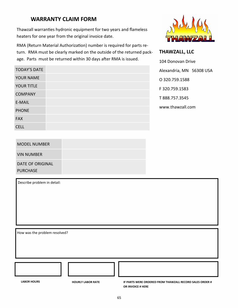
WARRANTY CLAIM FORM
Thawzall warranties hydronic equipment for two years and flameless
heaters for one year from the original invoice date.
RMA (Return Material Authorization) number is required for parts re
turn. RMA must be clearly marked on the outside of the returned pack
age. Parts must be returned within 30 days after RMA is issued.
THAWZALL, LLC
104 Donovan Drive
Alexandria, MN 56308 USA
O 320.759.1588
F 320.759.1583
T 888.757.3545
www.thawzall.com
TODAY’S DATE
YOUR NAME
YOUR TITLE
COMPANY
PHONE
FAX
CELL
MODEL NUMBER
VIN NUMBER
DATE OF ORIGINAL
PURCHASE
Describe problem in detail:
How was the problem resolved?
LABOR HOURS HOURLY LABOR RATE IF PARTS WERE ORDERED FROM THAWZALL RECORD SALES ORDER #
OR INVOICE # HERE