th cirp conference on assembly technologies and systems ... · 7thcirp conference on assembly...
TRANSCRIPT

International Academy for Production Engineering7th CIRP Conference on Assembly Technologies And Systems
Tianjin, ChinaMay 10 - 12, 2018
Research on Virtual-real Biaxial Real-time Error Compensation Based on Fuzzy
Control Theory
SunHongchanga,b, ZhangZhijinga* , JinXina ,Lilinac , ZhengZhongpenga ,ShaoChaoa
aSchool of Mechanical Engineering, Beijing Institute of Technology, Beijing 100081, China
7th CIRP Conference On Assembly Technologies And Systems
Outline1. Introduction2. Virtual-real biaxial kinematics principle of
PRS-XY hybrid machine tool3. The hardware design of virtual-real biaxial
real-time error compensation 4. Fuzzy controller specific design5. Algorithm simulation calculation
Verification6. Verification of the algorithm7. Conclusions
1

7th CIRP Conference On Assembly Technologies And Systems
1. Introduction
• 1.Hybrid Machine Tool (Hybrid PMT), belongs tothe concept of parallel machine tool category.
• 2.The hybrid machine tool mixes the parallelmechanism and the series mechanism, andcombines the characteristics of the two.
• 4.To a large extent to solve the restrictions oflimited machining region, so that the applicationof the parallel mechanism will be with moreflexible and practical.
2

7th CIRP Conference On Assembly Technologies And Systems
2. Virtual-real biaxial kinematics principle
3
(a) PRS-XY HMT(b)Coordinate frames
Fig. 1. PRS-XY HMT object and its Coordinate frames

7th CIRP Conference On Assembly Technologies And Systems
2. Virtual-real biaxial kinematics principle
• Virtual-real mapping relation of PRS-XYmechanism can be expressed as:
4
71 1 2 8 91
72 1 2 8 92
73 3 1 2 8 9
5 5 7,1 2 8, 9
6 76 1 2 8 9
( , , , , )( , , , , )( , , , , )( , , )
( , , , , )
é ùé ùê úê úê úê úê úê ú =ê úê úê úê úê úê ú
ë û ë û
g Q Q Q Q QPg Q Q Q Q QP
P g Q Q Q Q QP g Q Q Q Q QP g Q Q Q Q Q
1. Q1,Q2,Q7,Q8,Q9 are A, B, X, Y, Z virtual axis coordinates,
2. P1,P2,P3,P5,and P6 are rotary sub-joint B1 (linear motor drive 1), rotary sub-joint B2 (2 linear motor drive), B3 (3 linear motor drive), table X direction (X motor drive) and table Y direction (Y motor drive) joint coordinates, gi for the inverse function.
7th CIRP Conference On Assembly Technologies And Systems
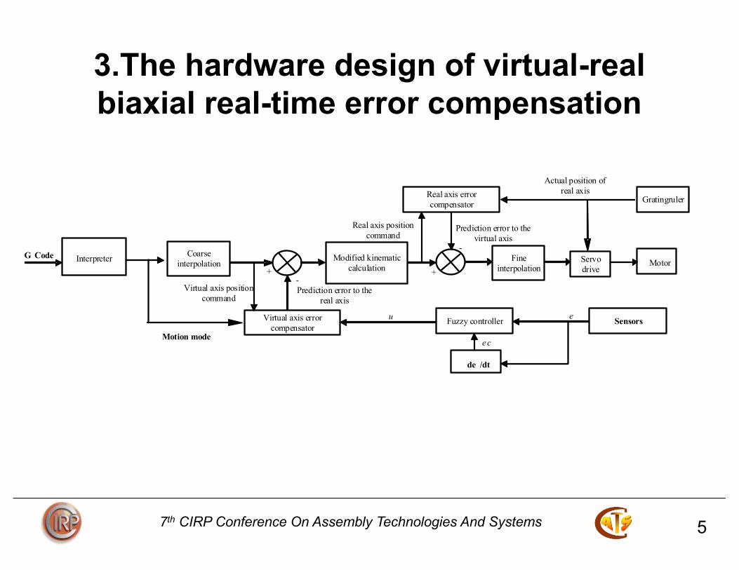
3.The hardware design of virtual-real biaxial real-time error compensation
5
Virtual axis error compensator
Interpreter
Modified kinematic calculation
Coarse interpolation
Motor
Servo drive
Real axis error compensator
Fine interpolation
G Code
Gratingruler
+ + -
-
Sensors Fuzzy controller e
de /dt
ec
u
Motion mode
Virtual axis position command
Real axis position command
Prediction error to the real axis
Prediction error to the virtual axis
Actual position of real axis

7th CIRP Conference On Assembly Technologies And Systems
4. Fuzzy controller specific design
6
According to the input and output fuzzy subsets of fuzzier, the fuzzy rules are established by using the conventional fuzzy conditions and the fuzzy relation "IF A AND B THEN C" to form the fuzzy algorithm which describes the control process.
7th CIRP Conference On Assembly Technologies And Systems
5. Algorithm simulation calculation of fuzzy error compensation theory
•
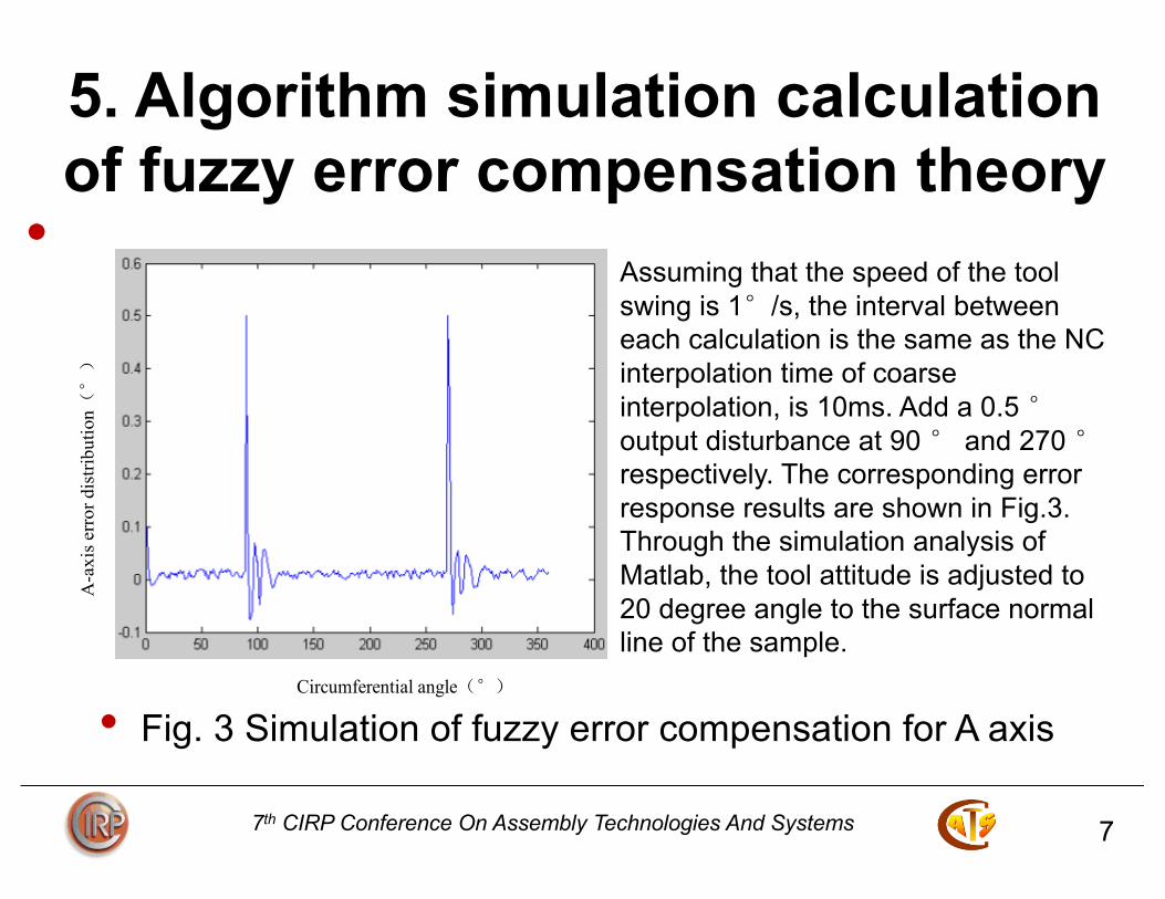
• Fig. 3 Simulation of fuzzy error compensation for A axis
7
A-a
xis e
rror
dis
tribu
tion(°)
Circumferential angle(°)
Assuming that the speed of the tool swing is 1°/s, the interval between each calculation is the same as the NC interpolation time of coarse interpolation, is 10ms. Add a 0.5 °output disturbance at 90 ° and 270 °respectively. The corresponding error response results are shown in Fig.3.Through the simulation analysis of Matlab, the tool attitude is adjusted to 20 degree angle to the surface normal line of the sample.

7th CIRP Conference On Assembly Technologies And Systems
6. Verification of the processing experiment of the algorithm
8
Fig.4 Sketch of the typical sample
Ball End Milling Cutter
Typical Sample
Movable Platform
Motorized Spindle
Fig.5 Chamfer cutting underthe compensation

7th CIRP Conference On Assembly Technologies And Systems
• In three conditions, the sample is processed under the condition ofuncompensated, real axis compensation and virtual -real biaxialcompensation, and the actual chamfering angle data of the afterprocessing are shown in table2. The machining accuracy of themachine is greatly improved after the virtual-real biaxial errorcompensation is adopted.
9
Table2 Comparison of compensation for sample processing (Unit: °)
MeasureAngle 30° 90° 150° 210° 270° 330°
Uncompensated 20.67 20.75 20.39 20.64 20.75 20.73
Compensatedbyrealaxis
20.31 20.27 20.28 20.39 20.17 20.31
CompensatedbybothRealandvirtualaxis
20.08 19.88 20.09 20.11 20.07 20.04

7th CIRP Conference On Assembly Technologies And Systems
7. Conclusions
10
1. In this paper, a new type of virtual-real biaxialNC based on parallel or hybrid mechanism isstudied.
2. Fuzzy control strategy is discussed for NCerror compensation, its effectiveness isverified by theoretical simulation.
3. The exper iment were des igned andprocessed before and after compensation toveri fy the effective of motioned errorcompensation method.

7th CIRP Conference On Assembly Technologies And Systems 11
Thankyou!