texas water utility handbook
TRANSCRIPT
CHAPTER 2
GROUND WATER SUPPLIES
ANDREW L. WILLIAMS, JR., P.E.
Consulting EngineerHouston, Texas
Ground Water is important to each person and to each living crea-ture. Proper management of both fresh and saline ground water re-sources is vital for our life style. Ground water managers and their col-leagues are important to each person served by their water systems. Theyguard our health, safety, and economic wellbeing by providing adequatequantities of acceptable quality water. In a large measure, our destinyand standard of living depend on good water management.
Commitment to provide water is an awesome responsibility. Muchlike marriage, contracting to provide water should not be undertakenhastily, without adequate knowledge of anticipated costs, or without eq-uitable provisions for meeting unanticipated changes. Changes are natu-ral and occur constantly, both structurally and cyclically. Preparing forchanges merits our best efforts.
The satisfaction and pleasure in being able to provide life-sustainingwater are immeasurable. The challenges and the self-giving demandsof the water industry appeal to people who are dedicated to the GoodSamaritan life style. They are good neighbors and true friends. Welcometo the great fraternity of water utility people.
Each ground water system is unique. The manager is challengedto recognize the individual features of each system in each phase of explo-ration, development and production. The benefits of optimal use of aground water system are obtained by detailed planning, sophisticatedtesting and evaluating test data, careful drilling and developing of eachproducing water well, proper selection of pumping equipment, and com-petent well field operations. Each step in the development and operationof a ground water system is essential to insuring a safe, reliable watersource with acceptable performance and service life.
Two-thirds of the world’s fresh water and 95 percent of the usablefresh water is stored below the land surface as ground water. Rememberthat less than 1 percent of the world’s water was drinkable before man

22 MANUAL OF WATER UTILITY OPERATIONS
began polluting. We cannot afford water pollution - there is not enoughwater available.
Ground Water Underlying Texas. - An aquifer is an under-ground formation that is permeable enough to yield economic quantitiesof water to wells. Aquitards and aquicludes are impermeable confiningbeds. Seven major aquifers and sixteen minor aquifers underlie morethan half of Texas. From the northwest to the southeast, the major aqui-fers occur on the land surface in outcrop areas called:
Ogallala (High Plains)Edwards Trinity (Plateau)Edwards (Balcones Fault Zone - Austin Region)Edwards (Balcones Fault Zone - San Antonio Region)Trinity GroupCarrizo - Wilcox FormationsGulf Coast GroupThe Gulf Coast Group includes the Chicot, Evangeline, and Upper
Jasper aquifers. Alluvium and bolson deposits occur in several regions.The sixteen minor aquifers yield large quantities of water in small areasor small quantities of water in large areas.
These aquifers store about 140 trillion gallons of rechargeable waterand receive about 1.6 trillion gallons average annual natural recharge.One trillion gallons of water can be visualized as about one cubic milevolume, or enough to fill the equivalent of about 10,000 -4strodomes.Metropolitan Houston uses about one Astrodome of water each day.More than half is pumped from wells. These wells tap aquifers averagingabout 300 feet in thickness composed of fine to medium-sized sands, withabout 20 percent pore space between sand grains. The volume of waterin the aquifer is 20 percent of its total thickness, which is equal to about60 feet of water depth. Therefore, one may visualize the Houston areaas being covered with a 60-feet depth of water equal to the pore volumeof the aquifer underlying the area. Then consider a cross-section of aqui-fer from outcrop to discharge or contact with salt water. Next, considerthe aquifer dimensions, volume, and movement of water in the GulfCoast region. These considerations vigorously exercise the imaginationto adequately conceive of the huge volumes of ground water in storage.
Texans currently use about 3.6 trillion gallons from wells annually.About one-half of municipal water (0.43 trillion gallons) is obtainedfrom ground water sources located in almost every county of the state.In some areas, however, the possible overdraft (excessive pumpage) ofground water is lowering water levels, causing major water supply prob-lems to occur now, or likely to occur in the foreseeable future.

GROUND WATER SUPPLIES 23
The adequacy of natural recharge to aquifers determines the feasi-bility of the safe yield approach to ground water management. In areaswhere natural recharge is negligible, mining at a decreasing annual ratemay be necessary and practical, dependent on aquifer hydrologic capa-bilities. More conjunctive use of both ground and surface water may berequired to satisfy increasing demands for water. Regional managementof water resources may improve efficiency and extend ground water pro-duction service life. Partial demineralization and blending of brackishsurface and ground water with existing water supplies may become morefeasible. Importation from remote sources may be necessary to meet in-creased demands and to alleviate water problems, such as overdraftingand land surface subsidence.
Hydrologic Cycle. - The natural circulation of water in the air,above and below the ground surface, is called the hydrologic cycle. Adrop of water moves from ocean to cloud, to rain, to surface infiltrationor runoff, to ground water, and back to ocean. Along the cycle, the watermay move through surface to ground to surface water systems manytimes and will change states from liquid to gas, to solid possibly, to liquid.Figures 1 and 2 illustrate an hydrologic cycle.
q Sand 0 Shale
FIG . 2-1. - Hydrologic Cycle.

2 4 MANUAL OF WATER UTILITY OPERATIONS
P R E C I P I T A T I O NRainfall. Snow. etc.
hhRUNOFF PERCOLATION TRANSPIRATION
FIG . 2-2. - Hydrologic Cycle.
Production of Water from Wells. - Ground water can be capturedby pumping water wells. The wells function in somewhat the same waythat dams and reservoirs capture surface water. The well structure islike the reservoir discharge penstock, in that it provides a means of accessto the ground water contained in the aquifer. The well pump is like thedam gate, in that it controls the rate of withdrawal from the reservoir.The aquifer filters suspended solids as water enters it, provides a conduitfor ground water flow, reduces water losses to the atmosphere, protectsand stabilizes water quality, and maintains artesian pressure when con-fined by aquitards. The portion of the aquifer in which the water levelsin the well do not rise above the top of the aquifer is called a water tableaquifer. The portion of the aquifer enclosed by aquitards, in which thewater level in the water well rises above the top of the aquifer, is calledan artesian aquifer. A flowing artesian well taps an artesian aquifer un-der sufficient pressure to cause the water level in the water well to riseabove the land surface. The water table is commonly called the waterlevel surface elevation inside the idle water well. Water levels fluctuatewith the rate and duration of pumping and other factors. For good groundwater management, it is essential to keep and frequently evaluate accu-rate and long-term well and pump performance records. In both produc-ing and idle wells, and observation wells, measurements of changes inwater levels, rate and duration of production, water quality, and operat-ing characteristics should be recorded regularly.
Locating a water well or well field involves investigation, explora-tion, evaluation, and ground water management through drilling, devel-oping, equipping, and producing of the well system. Figure 3 illustratesthe futility of folklore in searching for ground water. Consult the experts.

GROUND WATER SUPPLIES
(An Age Old ProblemI)
FIG . 2-3. - Folklore Searching for Water. -
It is essential to consult with competent and locally experienced pro-fessional ground water specialists, including engineers, scientists, tech-nologists, and drillers. In feasibility studies, search for suitable aquifers,evaluation of geologic, geophysical, and hydrologic characteristics of theaquifers, analyses of existing wells, test drilling and water quality sam-pling programming, design of water wells, test pumping evaluation,pumping equipment selecting, assessment of safe yields and impacts onregional hydrologic systems, there is no substitute for obtaining and im-plementing the best technical advice available. The professional fees aregood investments toward enjoying the benefits of long-term, efficient,and reliable ground water supplies.
Major technical concerns include well field location, number ofwells, pumping rates, well spacing, long term impacts on water levels,quantity, and quality as related to the aquifer under study.
Abundant ground water sources are associated with plentiful sur-face water, broad regional aquifers, deep filled valleys called bolson de-posits, and long river flood plains called alluvium deposits. Texas hasa range of 8 to 56 inches normal annual precipitation, diminishing fromeast to west along north-south somewhat irregular contours.
Fresh water is stored in significant volumes in some semi-arid and
26 MANUAL OF WATER UTILITY OPERATIONS
arid areas underlain by bolson, alluvium, and other deposits which re-ceive scant recharge. The deposits were laid down in earlier times underdifferent climatic conditions.
The water moves through most aquifers slowly, minimizing the ef-fects of wet and dry weather cycles. Velocities may range from feet peryear to feet per day. Measurement of approximate velocity involves de-termining the slope of the hydraulic gradient, porosity, and hydraulicconductivity, and can involve the use of tracers or environmental isotopesin the aquifer. The huge volumes of ground water stored in the aquifersfurther minimize the impact of droughts.
The occurrence, movement, pumping, and conservation of groundwater can be analyzed mathematically. Many aspects of ground watercan be measured and monitored physically. The effects of pumping, re-charging, and cleaning up pollution can be predicted over a wide rangeof time intervals. Predictions on the performance of major well fieldsdrilled twenty to forty years ago have proven quite accurate. Ground wa-ter managers can rely on competent ground water professionals to gener-ate accurate projections of well field performance required for effectivelong range planning and funding.
Life of a Typical Ground Water System. - The life of a typicalground water system can be visualized in a sequential progression as fol-lows:
Conceptual StudiesFeasibility AnalysesSiting of Test DrillingSampling ProgramDesign of Water Well FieldDrilling, Developing, and Pumping WellsSelection and Installation of Pumping EquipmentMaintenance of Production Capacity by Restorative Pump and/or Well Repairs, preferably when scheduledFigures 4 and 5 illustrate typical test drilling project data, including:Driller’s log describing thickness and appearance of formations pen-
etrated and sampledLithology log further describing formationsAlignment survey of bore to confirm suitability for casing and well
pump installationElectrical induction log to show characteristics of position,
thickness, and general water quality or the test drilledformations
Gamma Ray or (SP) for formation water quality data and forma-

GROUND WATER SUPPLIES 21.
FIG . 2-4. - Sample the Formations.
T-c
FIG 2-5. - Read the Logs.

28 MANUAL OF WATER UTILITY OPERATIONS
tion evaluationSpecial purpose logs to detect gas, radioactivity and mud cakeCaliper log to measure diameter of drilled or underreamed holeFigure 6 depicts a method of water sampling from up to 20 feet
thickness of aquifer by pumping from a temporary water well. The screensection is sealed above and below screen openings.
WATER QUALITY SAMPLINGFROM TEST WELL
Fig. 2-6 - Sample by Pumping.
D I S C H A R G E7 PIPING
- C A S I N G
- PUMP
- G R A V E L
- S C R E E N
Figure 7 illustrates the decision to complete the test hole as a pro-duction well or to abandon site.

GROUNDWATERSUPPLIES 29
FIG . 2-7. - Do You Complete the Test Hole as a Well?
Figure 8 depicts the first step in construction of a production waterwell. The test hole is reamed to the top of the aquifer. The reamed holeis about 4 inches larger in diameter than the casing. The casing is con-nected by water tight welded joints. The annular space outside the casingis pressure cemented from bottom to land surface. The casing providesaccess to the aquifer and prevents entry of water from land surface andfrom formations overlying the producing aquifer. The casing size is se-
onouTEcCCNWJCfW
Culwo I
02
aEAuEc TIE51MOLI!
HOLEOPSNWWI
PILOTW
l-4-l
CEUENT 5MOE
(ormmu)
c3~OMUPIPE-PuuFmCEUEW
YINIWJYw-55 HOUR5TO nAmNl
omum
Pa01 01
EUEUT5nm.uo
FIG . 2-8. - Construction of a Production Well.

30 MANUAL OF WATER UTILITY OPERATIONS
lected to house the pump and to afford installation of screen and gravelpack. The screen openings and gravel pack grain sizes are designed foreasy access of water to the well bore with minimum sand content.
Figure 9 depicts installation of screen with wash line for flushingin advance of screen.
W A L LC A K E
-SUNPACECASINQ
QNAVEL .
-v-
, LAP PIPE
KY-: ;.
1
I----.d 4UNDERREAMED
S E C T I O N
FIG . 2-9. - Installation of Screen.
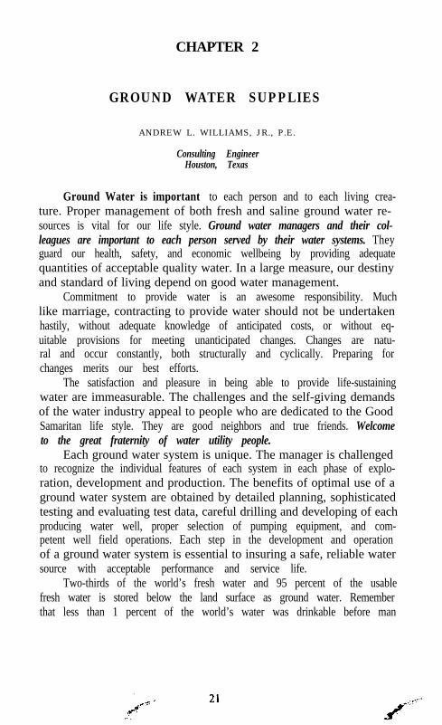
Figure 10 illustrates a development process using a tandem swabstraddle packer agitator. The perforations between the swabs allow injec-tion of well development solutions and, during reverse flow, allow remov-al of loosened fine grained solids. The agitator is lowered and raised re-peatedly like a piston in a cylinder to wash, surge, clean, and removefine grain size solids from the well bore. The filter gravel settles and sta-bilizes around the screen, filling the annulus outside the screen in theunderreamed hole. Additional filter gravel may be added during the lifeof the well. The filter gravel is sized to retain the aquifer sands in place.The screen opening, or gauge, is sized to retain the gravel filter in place.A contingency reserve supply of filter gravel is stored between the wellcasing and the lap section of the blank liner. The gravel can slip down-ward to fill underlying voids in the gravel pack. The well screen linerand gravel filter are designed for periodic cleansing and replacementwhen required. The screen length equals the full thickness of the produc-ing aquifer in optimal design for horizontal flow from the aquifer.Segments of blank liner are placed opposite aquitards. Keystone shapedscreen openings are used to allow self cleaning and easy flow of very small
GROUND WATER SUPPLIES 3 1
solids into the well bore. In addition to removal of mud cake on the faceof underreamed well bore, removal of the finer grained aquifer materialis frequently pumped from the well during development, pumping tests,and, at times, during the initial service life of the well. Use of the contrac-tor’s pumping equipment for development and the pumping tests is rec-ommended to avoid wear to the owner’s permanent pump. Sand, silt, andclay solids removal from the well could cause abrasive wear of pumpcomponents.
Mechanical/Chemical
. -. Wall Cake removed. Gr~val sl~bilircd. Formation llowingl Test Pump devclopmcnl
l Sur@ng.~Over producing
FIG . 2-10. - Development of Production Well, Phase 1.
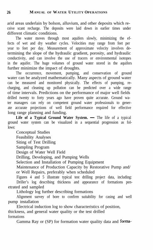
Figure 11 illustrates the use of temporary pumping equipment tocomplete well development by pumping and back washing to determinethe well’s performance characteristics. The test pumping equipment in-cludes measurement apparatus for water level, rate of flow, and suspend-ed solids content of water. Step tests of a few hours each are performedto measure performance characteristics at varying pumping rates. Theproduction test extends for a longer time interval to demonstrate compli-ance with specifications and guarantees. Trends in the regional aquiferwater levels are measured to accurately calculate specific capacity, wellefficiency, and to predict well performance over time. Specific capacityis defined as the gallons per minute of water produced per foot of water

32 MANUAL OF WATER UTILITY OPERATIONS
HYDRAULlC/CHEMlCAl.ON OFF
FIG . 2-11. - Well Development, Phase 2.
SPECIFIC CAPACITYYield and Drawdown Relationship
-
YIELD = 500 (IPM
A 20 BPM I0 = FOOT OF DRAWDOWN 9;
STATICXTER LEVELDAAWDOWN = 25’ 1 T’T:
,PUMPINDW A T E R L E V E L
FIG . 2-12. - Calculate Specific Capacity.
GROUND WATER SUPPLIES 3 3
level drawdown. Measurements of time periods after starting and stop-ping the well pump and the rate of production are important.
Figure 12 depicts calculation of specific capacity.Well efficiency is calculated from the actual specific capacity or
actual drawdown measured by pumping tests and compared to the theo-retical values obtained by applying Theis’ formula for confined aquifers.An analogy to heat-flow theory has been used since 1935 to better under-stand ground water behavior. An analogy of electrical current-flow isused in ground water analog modeling. Digital models are used to simu-late ground water movement.
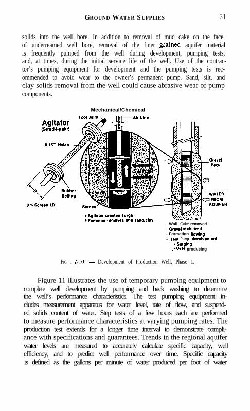
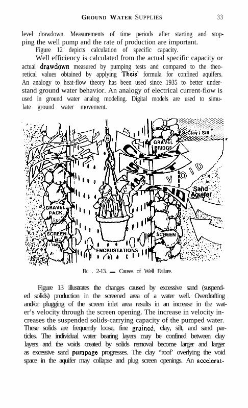
FIG . 2-13. - Causes of Well Failure.
Figure 13 illustrates the changes caused by excessive sand (suspend-ed solids) production in the screened area of a water well. Overdraftingand/or plugging of the screen inlet area results in an increase in the wat-er’s velocity through the screen opening. The increase in velocity in-creases the suspended solids-carrying capacity of the pumped water.These solids are frequently loose, fine grained, clay, silt, and sand par-ticles. The individual water bearing layers may be confined between claylayers and the voids created by solids removal become larger and largeras excessive sand pumpage progresses. The clay “roof’ overlying the voidspace in the aquifer may collapse and plug screen openings. An accelerat-
34 MANUAL OF WATER UTILITY OPERATIONS
ed increase in water entrance velocity in the remaining open screens ac-companies plugging of part of the screen openings. The solids contentof pumped water also can increase. Thus, the cycle continues until failureof the well structure. Sloughing and caving of clay roofs interrupts waterflow from the aquifer to the well bore. Failure of the well pump occursthrough solids abrasion, loss of bearing supports, and excessive vibrationof rotating parts. Failure of the water storage facilities, transfer pumps,and distribution system occurs by filling with solids pumped from thewell. All or any one of these failures can occur instantaneously or gradu-ally as a result of several factors. Most well failures are probably causedby improper well design, construction, development or operation. Prob-ably, over pumping is the easiest cause of failure to detect and to correct.For evaluating ground water system conditions, periodic measurementsof drawdown of water levels, solids content, water quality, and rates offlow are the essential data. Analyses of the data by competent groundwater specialists at regular time intervals will serve as preventative orcorrective steps to maintain water production efficiency and reliability.
Plugging of screen openings can result from the precipitation ofhardness scale, algal growth, iron deposits, bacterial growth, or variouscombinations. These conditions occur in relatively small local areas. Ex-perienced ground water specialists can contribute technical guidanceneeded for efficient restoration of well production. The use of solutionscomposed of detergents, acids, wetting agents, vibratory explosives, anddisinfectants may be appropriate. Various methods of treatments, chem-icals, mechanical actions, and techniques may be applicable for success-ful restoration of a well.
One cause of well pump, storage tank, transfer pump, and distribu-tion system failures can be avoided by controlling and separating thepumped solids from the pumped water. Ideally, the pumped water is freeof suspended solids upon entry into the well; however, many useful waterwells yield some suspended solids on commencement of pumping. Thewater entrance velocities at start-up far exceed the design rate until thedesign head pressure is reached. Loose rust, scale, and aquifer particlesmay be pumped to the surface on starting. A small trace of solids maybe produced continuously. Sand separators can be used to discharge sol-ids to waste, and, thus, protect storage, transfer pumps, and distributionsystem against solids accumulation.
Ground Water Conditioning may include aeration to improve tasteand odor, degasification to reduce methane, iron, and hardness content,demineralization, softening, fluoridation, and disinfection by chlorina-tion or ozonation. The alkalinity and acidity can be adjusted to inhibit

GROUND WATER SUPPLIES 35
corrosion of iron and steel and to mitigate scaling or precipitation. Se-questering agents can be used to alleviate red water problems associatedwith iron precipitation. The quality and temperature of ground waterare essentially stable, so that the water conditioning process requires mi-nor, if any, adjustments over time.
Service Life Aspects. - Ground water supply systems are tradi-tionally expected to provide water for at least thirty years, which normal-ly equals the time required to retire the bonds sold to fund construction.The pumping equipment normally requires repair or replacement ofcomponents at about 8 year intervals; but the unique characteristics ofeach individual system cause a wide variation in both service life andreplacement intervals.
In a nationwide study in 1982, inefficiencies in ground water irriga-tion supply systems were estimated to cause the waste of 7.6 trillion BTUof energy each year. These losses are largely the result of improper welldesign, lack of maintenance, and improper pump and power unit selec-tion. Energy waste in municipal systems merits continuous concern anddiligent efforts to control.
Aquifer characteristics limiting water withdrawal include grainsize, uniformity and distribution, thickness and permeability, confiningbeds, degree of consolidation of grains, chemical composition of forma-tions and water quality.
Water well characteristics affecting performance and efficiency in-clude drilling method, casing and screen design and placement, gravelfilter design and placement, well development, and casing cementing orsealing. Encrustation, corrosion, and sand pumping shorten service lifeand reduce efficiency.
Pumping equipment performance is dependent on proper design,selection, installation, operation, and selection of the power unit. Dam-age occurs by cavitation, air or sand pumping, encrustation, plugging,corrosion or any combination of these. Changes in operating conditionscan reduce pump performance efficiency.
Typically, about two-thirds of well construction cost involves labor,drilling rig use and third party subcontract services. It is economicallyprudent to design the well for maximum capacity and to specify qualitycasing, screen, and gravel. The typical operating and maintenance costsof water well and pumps may approximate 30 to 40 cents per 1,000 gal-lons pumped in 1985 dollars.
Recording Well and Pump Performance Data Regularly is Im-portant. - Ground water management is greatly enhanced by periodictesting of water well performance and pumping equipment condition.
36 MANUAL OF WATER UTILITY OPERATIONS
At least, annual review of test information will reveal changes in theaquifer, the well and the pump. These changes may result from changedconditions in the aquifer, the well, or the pump, separately or in combina-tion. The importance of accurate and regularly scheduled data collection,water quality analyses, and good record keeping practices becomes evi-dent when planning to increase withdrawals by expanding well fields;to modify withdrawal rates from wells; to restore production from a well;and to plan preventative maintenance. Good records and preventativemaintenance are required in the efficient management of reliable groundwater systems. Scheduled periodic evaluation of data is the best toolavailable to assess the impact of changes.
Sanitary Protection and Consideration. - The duties of the Wa-ter Hygiene Division of the Texas Department of Health include the en-forcement of the Rules and Regulations for Public Water Systems adopt-ed by the Texas Board of Health. These rules govern the design of watersystem facilities, changes in facilities, and minimum operating practicesto insure the production and distribution of safe, potable water.
Texans are so accustomed to the benefits of safe, potable waterstatewide that little thought is given to sanitary considerations. We havecomplete faith in the water industry’s commitment to delivering safe,potable water. Through education and enforcement, the regulatory agen-cies have contributed to establishing and maintaining proper watersystems in Texas for more than 100 years. These Rules, based on theCivil Statutes of Texas, relate to review of plans and specifications forfacilities construction, including an engineering report on new, existing,changes, or improvements to water system facilities. The water sourcequality and quantity conditions must comply with the Rules containedin Appendix B.
Comparison of Ground Water aud Surface Water Sources. - Incomparing ground water and surface water supplies, the advantages ofground water obtained from favorable aquifers usually include the fol-lowing:
The supply is located in or near the area of water use.The design water quantity is available regardless of weather
changes.The water quality is uniformly free of suspended solids, harmful
bacteria and viruses.The water temperature is normally constant year round.The water is potable as pumped after minimal disinfection, condi-
tioning, or treatment.The construction, operating, and maintenance costs are less.
GROUND W ATER SUPPLIES 37
In less favorable aquifers, the disadvantages of ground water mayinclude:
Higher mineral contentInadequate quantitiesIncreased costs of deep wells and pump settingsIncreased temperature which may require cooling before useSubsidence of land surfaceEncroachment of salt waterActivation of movement along faults
ACKNOWLEDGEMENT
The assistance of many persons contributed significantly to the fifthrevision of this chapter. Their interest and general support is gratefullyacknowledged. These persons include: Harl Barlitt, Alsay Corporation,Charles Schaefer, Bovay Engineers, John Seifert, William F. GuytonAssociates, and Frances Williams, all of Houston, Texas.
REFERENCES
1. AWWA No. 10003 Glossary - Water and Waste Water Control Engineering, 3rd Ed.2. AWWA A 100-84 Standard for Water Wells3. AWWA E-101.77, American National Standard for Vertical Turbine Pumps - Line
Shaft and Submersible Type4. AWWA M21, Ground Water5. AWWA 200167, Improving Well and Pump Efficiency6. AWWA, Small Systems Resource Book7. AWWA 20223, Design and Construction ofSmall Water Systems - A Guide for Man-
agers8. EPA-570/9-75-001 Manual of Water Well Construction Practices9. NWWA, Ground Water - Defined, National Water Well Association, 6375 Riverside
Dr., Dublin, Ohio 4301710. R. Allan Freeze and Cherry, John A., Ground Water, Prentice-Hall. 1977.11. Water for Texas Vol 1 - Executive Summary, Vol. 2 - Technical Appendix, Texas Wa-
ter Development Board. 1984
CHAPTER 3
SURFACE WATER SUPPLIES
WILLIAM F. BUCHHOLZ. Jr.
Vice President, Camp Dresser & McKee Inc.
Texas receives an average of about 413 million acre-feet of rain peryear. Some of this becomes ground water, some is transpired back to the’atmosphere by vegetation, and some is evaporated. The remainder entersour streams and rivers and is available as surface water.
This chapter discusses the methods commonly used to study howto best capture and control this water, the economic factors which influ-ence the development of surface water projects, methods of operatingreservoirs, and the policy decisions made which govern all of these activi-ties. Analyses can be simple and straightforward or complex, sometimesinvolving recent computer techniques. This chapter presents the histori-cal methods, touches on the more sophisticated methods, and mentionsrecent changes which may alter our ways of thinking about surface watersupplies, and their utilization.
SURFACE WATER PATTERNS
Stream flows vary both geographically and with time. Geographi-cally flow patterns match rainfall patterns. There is much more wateravailable in East Texas than in West Texas. Table 3-l illustrates this.The average runoff in the Sabine Basin is more than twenty times thatin the Canadian Basin.
In addition to geographical variability there is variation with time.West Texas streams are “flashy”; it is not unusual for the streams tobe dry except for two or three times a year, when they may breach theirbanks and create havoc. The variations with time are more problematicthan the geographical variations for the analyst because it is only thegeographical over which the developer of a surface supply has any con-trol.
THE NEED FOR RESERVOIRS
Texas has no natural lake entirely within its boundaries, yet, on the
38

SURFACE WATER SUPPLIES 39
average, in much of Texas there is enough rain and thereby surface waterin the streams and rivers to satisfy local, long-term needs. The great vari-ability in flows, however, means that at times there is too much waterand at other times not nearly enough: Texas’ typical pattern of flood anddroughts. These conditions of enough water “on the average” but withmore or less recurring cycles of very high and very low flows makes theneed for storage of water the obvious solution. If the shape of the basinis appropriate, soil and other conditions are economically favorable,building reservoirs is the natural and most advantageous choice.
TABLE 3-1. - Summary of Average Annual Runoff per Square Mile in Major Texas RiverBasins during the Period 1940-1956. One Acre-Foot Equals 326,000 gal-l o n s .
River Basin
Contributing DrainageArea in Texas(Square Miles)
Average Runoff19404956
(AC-Ft/YdSq Mi)
Canadian River Basin 9,405 34Red River Basin 19,191 124Sulphur River Basin 3,558 669Cypress Creek Basin 2,812 569Sabine River Basin 7,383 682Neches River Basin 9,995 584Trinity River Basin 17,845 326San Jacinto River Basin 3,932 491Brazes River Basin 35,400 149Colorado River Basin 29,863 58Lavaca-Navidad River Basin 2,475 256Guadalupe River Basin 6,033 159San Antonio River Basin 4,217 95Nueces River Basin 16,954 28Rio Grande River Basin 40,045 -14*Coastal Basins 14,487 306Rio Grande Drainage 1,777 35
Texas as a Whole 225,372 172
l Including effects of treaty provisions.
All of these conditions have existed and there is a long history ofconstructing reservoirs in Texas; more than 5,700 of them now exist,ranging in size from Lake Texoma, 5,380,OOO acre-feet, and ToledoBend, with 5,102,OOO acre-feet of storage, to the almost innumerablesmall stock tanks built by farmers and ranchers. This has been drivenby Texas’ economy, which has been one of strong economic growth, bothagriculturally and industrially, an expanding population, and abundantnatural resources, creating the need for reservoirs and helping provide
40 MANUAL OF WATER UTILITY OPERATIONS
the money to build them.Reservoirs benefit downstream users by reducing, or, in some cases
eliminating, downstream flooding, and benefit all users by storing waterfor use during droughts by providing a secure source for drinking, indus-try, and agriculture. Their existence also can produce recreation, gener-ate electricity and provide aesthetic pleasure. Reservoirs are a way oflife in Texas.
ENGINEERING ANALYSIS OF RESERVOIR SITES
The multiple uses of reservoirs raises problems. Occasionally theseuses are complimentary, for example, storing water to prevent down-stream flooding provides a supply during droughts. Also they can be con-tradictory; releasing water to produce power may reduce the water avail-able for other purposes. When deciding whether or not to build an im-poundment, and if so the location, size and uses must be reconciled. Inaddition is the question of who should pay and how much. These are com-plex problems: technical, economic, and political.
General Site Selection. - A suitable reservoir site should be se-lected on the basis of a number of interrelated engineering and economicfactors. There are eight engineering factors. The shape of the basinshould allow storing of large amounts of water by building relativelysmall dams. A narrow, deep gorge fanning out into a broad valley is ideal.Few such sites exist in East Texas, and in West Texas many sites arejust the opposite. Soil conditions are critical. Above all, soil should pro-vide a solid foundation; it also should resist seepage and provide suitablematerials for construction. It is good if the area to be flooded presentsfew problems; best is a sparsely populated, low value land, with few treesand little vegetation, and no major roads or railroads. The shape shouldprevent short-circuiting of stored water and the rise and fall of the waterlevel should not leave extensive mud flats on the bottom of the reservoir.Related to the flooded basin is the downstream area which is to be protec-ted; the uses of this protected land must be considered. All water rightsand water quality must be analyzed; finally, the environmental impactsmust be investigated. In Texas this is a major issue and in some instancesreservoir construction has been postponed for many years for environ-mental conflicts to be resolved.
Period of Use. - The useful life of a reservoir is determined oneconomic factors. The following must be considered:
1. The useful life of the structure and related equipment.2. The ease with which the reservoir might be expanded.

SURFACE W ATER SU P P L IE S 4 1
3. The expected rate at which municipal, industrial, and agricul-tural water needs will grow.
4. The interest rate used in financing construction.5. Inflations’ effect6. How the system will function in its early years when it is probably
underused compared to its later years.Estimated life expectancy for dams have ranged from 25 years for
small structures to 50 years for large structures, but it is now commonto expect that for major facilities the minimum should be 50 years. Res-ervoirs created during the depression of the 1930’s are functioning welltoday.
There is a rule of thumb that for a major dam 20 years elapse fromconcept to use. Thus, foresight and rigorous planning are essential to cre-ating any reservoir. It is not possible to “wait to the last minute” to plana reservoir.
Basic Methods of Analysis. - When analyzing a potential reser-voir site the initial question is: How much water should the reservoir hold,and therefore, how big should the dam be? The answer depends upon
too-5;6
g coo- cmulrtln Yithdrawal
5 Rescwoir Full
2E 5DO-
';
E8 400-
55
0
CLmulatlve Ruloff
Stert of Dry Period
D~""""l'l 1012 3 4 5 6 78 9 10 11 12
Ibaths
FIG . 3-l. - Typical Rippl or Mass Diagram showing Relationship Between Inflow andWithdrawal.

4 2 MANUAL OF WATER UTILITY OPERATIONS
how water flows into the reservoir and how water will be withdrawn fromit.
One way to answer this and related questions, is through the useof a Mass Diagram, developed by Rippl in 1883. It is simple in its ele-gance.
The method is illustrated in Figure 3-l. Cumulative runoff is plottedagainst time. The cumulative rate of withdrawal is similarly plotted, withthe starting point tangent to the runoff plot at the start of the dry period.The maximum difference between these two curves is the maximum defi-ciency the reservoir will experience. If the cumulative draft line does notintersect the cumulative runoff line, the reservoir will not completely re-fill before the next cycle and this could cause trouble in future years.
With all of this information, it is possible to estimate how low thewater will get, when water will be spilled, and what the water level willbe at any one time. It is possible to use non-constant withdrawal ratesand to do the analysis mathematically rather than graphically, withmuch more accurate results.
99.9 , , , , , , I I I I I I I I p’
146 mg onw in l@l yarn
99 137mgonwin5oywrs
123 mg onw III 20 years
95
W-
so-
70 -
so-50-
Straight linr of best fit
3-2. - Frequency Distribution of Required Storage plotted on Arithmetic-Probability Paper.

SURFACE W ATER S UPPLIES 43
The Rippl Method may be carried out again and again for everyyear of record, superimposing future withdrawal rates onto past runoffrates. However, this method, in its clear simplicity, ignores a major obvi-ous fact that past flows are not likely to repeat themselves precisely andthere are no assurances that the patterns of the past will be those of thefuture. Historical flow data are statistical values. Therefore, statisticalmethods have been developed to account for these variations. In the mostcommon method, frequency distribution plots are created. Data are ar-ranged in order of magnitude and the percent of time a specific valueis equalled or exceeded is calculated and plotted against the values, typi-cally on arithmetic-probability paper. See Figure 3-2. It is then possibleto choose a design storage value which is exceeded, say, only 5% of thetime; this means that once every 20 years, on the average, we may expectto run out of water. To choose this value is a policy decision. Are policymakers willing to accept this risk or would they prefer to be safer andrun out of water on the average only 1% of the time (once every 100years), and are those who pay for the construction willing to pay the extracost for this protection? These are important questions.
It must be remembered that statistical analyses are based on histori-cal records and are “on the average.” Existing records may include manyunusual years and thus not accurately reflect the future, and “on theaverage” does not mean that if the 100 year storage value is exceededthis year that it will not be exceeded again for 100 years; it may happenagain next year.
There are other difficulties with statistical analyses. Frequently,records are available for fewer years than the proposed economic life ofthe project; to extrapolate to a 100 year design condition with only 50years of data is treacherous. Also, it is the years of high flow and of lowflow which are the years of interest and it is precisely these years wherethe least data are available. Those data are the least reliable also. Finally,Texas is developing rapidly and changing conditions alter runoff patternsand ran off from a pasture 50 years ago may now be running off of asuburban development; the past does not accurately predict the future.
Much study has gone into overcoming the deficiencies of mass diag-rams and frequency analyses. The developed methods are complicated,involve use of probabilistic, statistic and/or simulation techniques withthe help of sophisticated computer programs. Because of their complexi-ty, these complicated advanced methods should be applied only by prop-erly trained experts.
ECONOMIC ANALYSIS OF RESERVOIR SITES
Methods of Analysis. - Projects are analyzed economically for

44 MANUAL OF WATER UTILITY OPERATIONS
two reasons. First, to see if building a project makes economic sense, andsecond, if there are multiple project choices which might be built, to seewhich is the best, that is, range the projects in an order of desirability.There are a number of methods and each has its strengths and weak-nesses. There is much theory and discussion about the different methodsbut the consensus is that the Present Worth (PW) and Benefit/Cost Ra-tio (B/C methods are the most applicable and that the PW method isthe better of these two.
In the PW method, the dollar value of the benefits accruing to aproject for each year of its life are discounted back to the present at acertain interest rate (similar to calculating mortgage payments, but inreverse) and from this is subtracted the cost of building the project andthe discounted operating and maintenance costs. If the benefits aregreater than the costs, the project should be built; if less, it should not.This can be expressed as follows:
PW = Present Value of Benefits - Cost of Construction -Present Value and Cost of Upkeep
If PW exceeds zero the project should be built. If multiple projects arebeing analyzed, the one with the greatest PW should be built first, theone with the second highest PW second.
In the B/C method, the calculations are identical, but the presentworth of the benefits is divided by the present worth of the costs. Thiscan be expressed as:
B/C = Present Value of BenefitsCost Construction + Present Value of Upkeep
If B/C exceeds 1 .O the project should be built; if less than 1 .O it shouldnot. The project with the highest B/C ratio should be built first. Al-though both methods will give the same build-no build answer, when ran-king projects they can, under certain circumstances, give different ran-kings.
Discussion of Methods of Analysis. - There are a number ofproblems, both theoretical and practical, with both of these methods. Themost devilish is uncertainty. Capital costs (construction costs) are theeasiest to estimate; but change orders and unforeseen circumstancesmake even these problems for the analyst. Historically, the hardest prob-lem has been estimating benefits. It has proven extremely nettlesometo put a dollar value on protecting downstream land from flooding, or

SURFACE W ATER S UPPLIES 4 5
on the future benefits of a water supply, or the most challenging of alland, in Texas often of great importance, the benefits of recreation. Whatinterest rate to use is of high importance. A private organization has someidea of what rate to use because it must borrow money in the marketplace. A non-federal public agency has a more difficult time, and if theproject is federally financed the difficulty is that the decision is moreone of policy than technical.
The timing of projects impacts both methods of analysis, and fre-quently the analysis is clouded when a number of projects are interrela-ted and it is hard to establish which benefits should be attributed to whichproject.
If projects have different life expectancies or different values re-maining at the end of their lives, the analysis is complicated. If the “flowof benefits” varies considerably, one having large early benefits and theother large late benefits, there are problems. Finally, if the size of twoprojects vary greatly the analysis is again affected. Of all of these ob-stacles the most important one is the uncertainty associated with calcu-lating the benefits and costs and too often there is too much importancegiven to subjective benefits. Engineering still prevails. If reasonably cor-rect estimates of costs and benefits are available, ranking, guided bycommon sense, will get the job done. Being too sophisticated gives a falseimpression of accuracy and people tend to get trapped into relying tooheavily on the results without considering the reliability of the sourcesof the data.
DES!GNING DAMS
Dams are designed on two levels. Preliminary design validates theengineering analysis and provides cost data. Final design produces plansand specifications for construction. The engineering process is identical;it is a matter of detail.
FIG . 3-3. - Typical Cross-Section of Earth Dam Embankment and Core Trench. Notto Scale. e
46 MANUAL OF WATER UTILITY OPERATIONS
Almost all major dams in Texas have compacted earth em-bankments with a protective blanket of gravel and an outer layer of stoneriprap on the upstream face. If rock is plentiful and cheap often the em-bankment is composed mostly of rock and the inner zone is of select, im-pervious material, placed to insure water tightness. A core trench is typi-cally excavated to a safely impervious foundation and then backfilledwith selected, compacted material to prevent seepage. Figure 3-3 is atypical cross-section.
AREA IN l,ooO ACRES50 40 30 lo 10 0
0 z o o 400 600 so0 l.OCQCAPACITY IN l,OW ACRE-FEET
FIG . 3-4. - Typical Reservoir Area Capacity Curves.
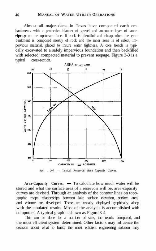
Area-Capacity Curves. - To calculate how much water will bestored and what the surface area of a reservoir will be, area-capacitycurves are devised. Through an analysis of the contour lines on topo-graphic maps relationships between lake surface elevation, surface area,and volume are developed. These are usually displayed graphically alongwith the tabulated results. Most of the analysis is accomplished withcomputers. A typical graph is shown as Figure 3-4.
This can be done for a number of sites, the results compared, andthe most efficient system determined. Other factors may influence thedecision about what to build; the most efficient engineering solution may
SURFACE W ATER SUPPLIES 47
not be the best overall solution. A lake with a small surface area relativeto the volume of water stored reduces both land costs and evaporationlosses, but it may increase the cost of the dam.
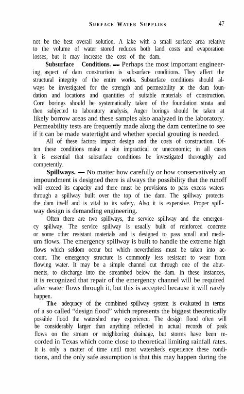
Subsurface Conditions. - Perhaps the most important engineer-ing aspect of dam construction is subsurface conditions. They affect thestructural integrity of the entire works. Subsurface conditions should al-ways be investigated for the strength and permeability at the dam foun-dation and locations and quantities of suitable materials of construction.Core borings should be systematically taken of the foundation strata andthen subjected to laboratory analysis, Auger borings should be taken atlikely borrow areas and these samples also analyzed in the laboratory.Permeability tests are frequently made along the dam centerline to seeif it can be made watertight and whether special grouting is needed.
All of these factors impact design and the costs of construction. Of-ten these conditions make a site impractical or uneconomic; in all casesit is essential that subsurface conditions be investigated thoroughly andcompetently.
Spillways. - No matter how carefully or how conservatively animpoundment is designed there is always the possibility that the runoffwill exceed its capacity and there must be provisions to pass excess watersthrough a spillway built over the top of the dam. The spillway protectsthe dam itself and is vital to its safety. Also it is expensive. Proper spill-way design is demanding engineering.
Often there are two spillways, the service spillway and the emergen-cy spillway. The service spillway is usually built of reinforced concreteor some other resistant materials and is designed to pass small and medi-um flows. The emergency spillway is built to handle the extreme highflows which seldom occur but which nevertheless must be taken into ac-count. The emergency structure is commonly less resistant to wear fromflowing water. It may be a simple channel cut through one of the abut-ments, to discharge into the streambed below the dam. In these instances,it is recognized that repair of the emergency channel will be requiredafter water flows through it, but this is accepted because it will rarelyhappen.
The adequacy of the combined spillway system is evaluated in termsof a so called “design flood” which represents the biggest theoreticallypossible flood the watershed may experience. The design flood often willbe considerably larger than anything reflected in actual records of peakflows on the stream or neighboring drainage, but storms have been re-corded in Texas which come close to theoretical limiting rainfall rates.It is only a matter of time until most watersheds experience these condi-tions, and the only safe assumption is that this may happen during the

48 MANUAL OF WATER UTILIT’Y OPERATIONS
operating life of the dam.Normal practice is to build the dam high enough to allow some free-
board above the maximum high water level which could occur duringthe design flood. This is done to keep waves from breaking over the topof the dam at the height of a storm. The amount of freeboard will vary,depending on reservoir location, depth, size, and shape. Characteristical-ly, it will range between three and six feet.
Service Outlet and the Diversion Structure. - For most reservoirsit must be possible to release water and lower the lake level. This provi-sion, known as the service outlet, consists of some form of conduit, con-trolled by gates or valves, passing through an abutment or under the damat a level relatively near the bottom of the reservoir. If the outlet passesunder the dam, it is desirable to place the control mechanism at the up-stream end, so that there is no water pressure in the conduit when it isshut off. This typically consists of an intake tower, standing in the waterat the upstream toe of the dam, with several gated ports for the entryof water from the lake. The service outlet conduit connects the intaketower to an outlet channel on the downstream side of the dam. Wheneverwater from a reservoir is to be diverted through a pipeline or a canal,it is necessary to provide for the control, measurement, and often thepumping of the diversions. These may be handled through a separatediversion structure, or they may be combined with the service outlet fa-cilities.
Conflicts and Relocations . - Building a reservoir covering an areawith water which may contain houses, utilities, and privately owned land,creates conflicts which must be resolved. Often there are environmentalconflicts which must be considered. All of these can greatly delay a proj-ect and impact its economics, but they must be satisfactorily resolved.
Sedimentation . - All streams carry sediment, the amount depen-ding upon the basin’s soil conditions, how and to what extent the landis protected by vegetation and man-made features, and the rate and ex-tent of rainfall and runoff. In Texas there is a vast difference in theamounts of sediment carried by different rivers. According to Soil Con-servation Service records, the Guadalupe River above New Braunfelscarries 2200 cubic feet of silt per year per square mile while the DoubleMountain Fork of the Brazos carries 65,000 cubic feet per year persquare mile, 30 times as much as the Guadalupe.
The amount of sediment carried by a stream influences dam con-struction because as water entering a reservoir slows the sediment settlesand takes up reservoir capacity which would otherwise be water, therebyreducing useful capacity. Over time, this can become significant and
SURFACE W ATER S UPPLIES 4 9
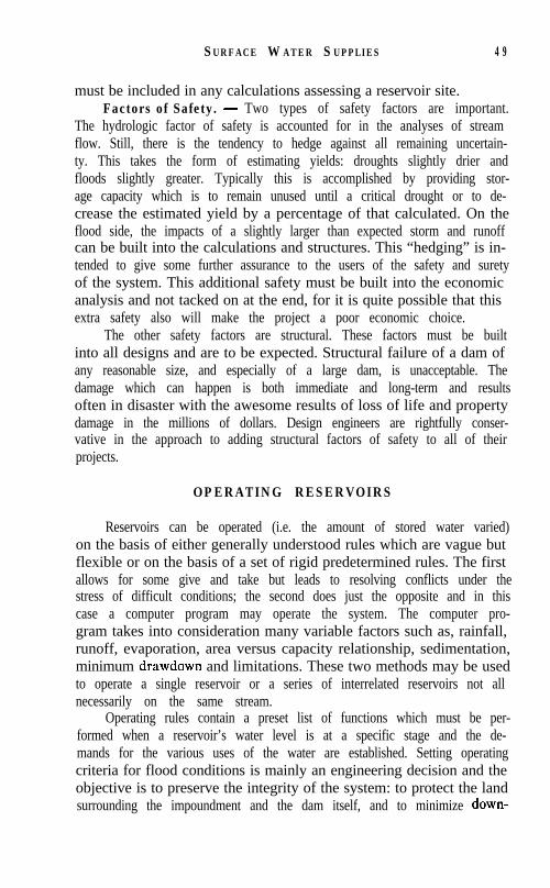
must be included in any calculations assessing a reservoir site.Factors of Safety. - Two types of safety factors are important.
The hydrologic factor of safety is accounted for in the analyses of streamflow. Still, there is the tendency to hedge against all remaining uncertain-ty. This takes the form of estimating yields: droughts slightly drier andfloods slightly greater. Typically this is accomplished by providing stor-age capacity which is to remain unused until a critical drought or to de-crease the estimated yield by a percentage of that calculated. On theflood side, the impacts of a slightly larger than expected storm and runoffcan be built into the calculations and structures. This “hedging” is in-tended to give some further assurance to the users of the safety and suretyof the system. This additional safety must be built into the economicanalysis and not tacked on at the end, for it is quite possible that thisextra safety also will make the project a poor economic choice.
The other safety factors are structural. These factors must be builtinto all designs and are to be expected. Structural failure of a dam ofany reasonable size, and especially of a large dam, is unacceptable. Thedamage which can happen is both immediate and long-term and resultsoften in disaster with the awesome results of loss of life and propertydamage in the millions of dollars. Design engineers are rightfully conser-vative in the approach to adding structural factors of safety to all of theirprojects.
OPERATING RESERVOIRS
Reservoirs can be operated (i.e. the amount of stored water varied)on the basis of either generally understood rules which are vague butflexible or on the basis of a set of rigid predetermined rules. The firstallows for some give and take but leads to resolving conflicts under thestress of difficult conditions; the second does just the opposite and in thiscase a computer program may operate the system. The computer pro-gram takes into consideration many variable factors such as, rainfall,runoff, evaporation, area versus capacity relationship, sedimentation,minimum drawdown and limitations. These two methods may be usedto operate a single reservoir or a series of interrelated reservoirs not allnecessarily on the same stream.
Operating rules contain a preset list of functions which must be per-formed when a reservoir’s water level is at a specific stage and the de-mands for the various uses of the water are established. Setting operatingcriteria for flood conditions is mainly an engineering decision and theobjective is to preserve the integrity of the system: to protect the landsurrounding the impoundment and the dam itself, and to minimize down-

50 MANUAL OF WATER UTILITY OPERATIONS
stream flooding. This necessitates releasing water from storage aheadof high inflow so that it can be held and not be added to the already highflows expected downstream. Under extreme circumstances, a decisionmust be made to suffer losses from flooded impoundments or from down-stream flooding. Low flow operating criteria are more difficult to estab-lish. Keeping water for drinking usually has the highest priority with
. the conservation measures imposed on all uses becoming stricter as thedanger becomes greater.
General operating criteria under typical conditions of neither floodnor drought are more difficult to implement and must be rationallydrawn. Mathematical formulae are devised and followed. These rulesstate, for example, that if a reservoir’s water is at some specific level andis statistically expected to rise, then so much water should be releasedto create power but not so much as to flood downstream and the remain-der retained for other planned uses. All legal obligations must be builtinto these formulae and the operator of a reservoir must consider theeconomics before he enters into contracts which impact his operation.
Setting these criteria requires policy decisions of the most difficultkind. For example, as water levels become low with no rain in the forecastand two demands exist, say drinking water and power generation, butpower production creates more revenue, should the turbines continue torun at the expense of a failing drinking water supply? If not, at whatpoint should the turbines be shut down so that citizens can drink? Or,should the price of municipal water supplies be increased to give themeconomic priority over power production? Building-in answers beforethese situations arise places the operator on solid legal, economic, ethical,and political grounds.
These decisions become more complex if a group of reservoirs areoperated as a system. One long summer the Dallas Water Utilities foundit less costly to draw and treat water from one reservoir rather than an-other. This considerably lowered the level in one reservoir. Those operat-ing marinas, boat docks, and other recreational facilities, as well as thecitizens using the impoundment being depleted, complained vociferouslyat the decision and it was altered.
The state-of-the-art is such that few rigorously developed mathe-matical operating conditions exist but the movement is in that directionas the demands for Texas’ water becomes more acute.
WATER QUALITY
A proposed reservoir’s water quality is now usually predictable. Thisis because there are enough existing impoundments, and direct compar-
SURFACE WATER SUPPLIES 5 1
isons can be made with good results. Water of poor quality can be madeto meet required quality standards with treatment if economically justifi-able, and it is generally accepted that drinking water supplies be the mostpristine.
Reservoir water quality must be constantly monitored so thatchanges can be dealt with before any deteriorating condition becomescritical.
WATER REUSE
Recently a new source of surface water is being considered. It isthe effluent from waste water treatment plants. As reservoir sites becomemore costly to develop and more distant from the user, the restrictionsbeing placed on waste water discharges are becoming ever more strin-gent. The result is a source of water which, with slightly more treatmentthan otherwise received, may be suitable for some municipal, agricul-tural, and industrial uses. The extra cost of the additional treatment ofwaste water and its distribution is often less than that of developing anewer, farther, but purer source. The direct use of treated waste waterfor domestic consumption, no matter how high the degree of treatment,is not yet being advocated. Many industries, however, are using treatedwaste water for both cooling and process water. In Odessa, for example,El Paso Products uses the City’s treated effluent which is suited for manymunicipal uses, such as watering golf courses, lawns, medians, and parks,keeping small lakes replenished, and in smaller communities may evenbe used as a grey water system, carrying away sewage. Aside from thecost factor, treated effluent has three other positive attributes:
1. It is drought-proof. In the hottest, driest months, when water isused the most and is often in short supply, it is always available.
2. If it is to be used to irrigate it contains many beneficial nutrientswhich are not in drinking water.
3. Most important, by supplanting some drinking water uses it ex-tends the life of those purer sources. Higher quality waters are preservedfor higher uses.
Until water reuse becomes common, each project must consider fourconditions:
l.If it might be ingested it must be shown to be safe, at least as safeas existing sources. The health of our citizens is paramount.
2. A public education program must prepare the citizens. Those whoare to use the water must accept it.

52 MANUAL OF WATER UTILITY OPERATIONS
3. The economics must be solid. The cost of purifying and distribut-ing this water must be less than that of using another source.
4. All water rights questions must be resolved.
WATER RIGHTS
In Texas, surface waters are owned and subject to regulation by theState. To use State waters a permit must be obtained from the TexasWater Commission. The concept of water rights is to give preferenceto the most important uses and to give priority to those rights of longeststanding. In practice, the system is complex.
An applicant must file detailed information stating what is to bebuilt, how much water is to be used, and for what purposes. Once thisinformation is properly submitted all who might be impacted by the pro-posed use are notified and they may file a protest. A public hearing isestablished. At the hearing all sides are heard. Emphasis is placed onthe need for the water, proof that unappropriated water is available, andthat the project protects public safety. If the Commission decides in favorof the request a permit is issued. The user must then report annuallyon the amount of water used and that he is complying with all other re-quirements of the permit. Thus, not only are the waters of the State pro-tected but they are allocated on the basis of what is best for the citizensof the State.
In 1985, legislation consolidated many functions of previous agen-cies into the Texas Water Commission and gave the new agency far-reaching authority. Some of these new provisions are:
1. Water and utility service proceedings may be informal, thusspeeding up the process and reducing costs.
2. A system for releasing and diverting water to protect rights andavoid the loss of released water.
3. If water has not been used beneficially under a permit for tenyears, proceedings will be initiated to cancel the permit.
4. The State will be divided into water divisions to administer adju-dicated water rights.
The impacts of this new legislation are only beginning to be under-stood and the rules and regulations which will be devised to carry outits mandate will greatly change how water is controlled and administeredin Texas.

CHAPTER 6
PRETREATMENT OF SURFACE WATER SUP-PLIES
WALTER J. O’BRIEN, PhD., P. E.
Black and Veatch, Dallas, Texas
AND
W. T. BALLARD, P. E.
Formerly Regional Engineer, Texas Department of Health, Tyler, Texas
Pretreatment of surface water supplies accomplishes the removalof certain constituents and materials that would interfere with or placean unnecessary burden on the conventional water treatment facilities.This includes:
1 . The removal of debris from water from rivers and reservoirs thatwould damage or clog pumping equipment.
2 . Destratification of reservoirs to prevent anaerobic decompositionwhich may result in the reduction of iron and manganese fromthe soil to a state that would be soluble in water causing subse-quent removal problems in the treatment plant. The productionof hydrogen sulfide and other taste and odor producing com-pounds also results from stratification.
3. Chemical treatment of reservoirs to control the growth of algaeand other aquatic growths that could result in taste and odorproblems.
4. Presedimentation to remove excessively heavy silt loads prior tothe treatment processes.
5. Aeration to remove dissolved odor-causing gases such as hydro-gen sulfide and other dissolved gases or volatile constituents andto aid in the oxidation of iron and manganese although manga-nese or high concentrations of iron are not removed in the deten-tion provided in conventional aeration units.
6. Chemical oxidation of iron and manganese, sulfides, taste andodor producing compounds and organic precursors that may pro-
126

PRETREATMENT OF SURFACE W ATER 1 2 7
duce trihalomethanes upon the addition of chlorine.7. Adsorption for removal of tastes and odors.
SCREENING
Screening is included in the design of intake structures and is provid-ed in the form of bars or screens over the intake opening to prevent debrisfrom entering the raw water line and possibly causing clogging or dam-age to the pumps. If the debris load is extremely heavy, mechanicallycleaned screens are provided. The fixed bar rack or screen may have toperiodically be cleaned manually. When cleaning the screens, eithermanually or mechanically, the removed debris should be disposed of sothat it is not returned to the screened opening.
DESTRATIFICATION OF RESERVOIRS
Thermal stratification of a reservoir occurs when a warm layer ofwater overlays a colder zone. In temperate zones, stratification occursduring the spring or summer when air temperature is higher than thewater temperature resulting in a lighter warmer water on the surfaceof the reservoir. To aid in understanding how stratification occurs, thespecific gravities of water at various temperatures are listed below:
Temperature, deg. C Specific Gravity0 0.999874 1 .ooooo
1 0 0.9997320 0.9982330 0.99567
Water has its greatest density at 4 deg. C (39.2 deg. F.).When stratification occurs, there are three layers in the reservoir.
The upper warmer layer is the epilimnion; the lower colder layer is thehypolimnion; and the layer in between is the thermocline (See Fig. 6-l).In the thermocline, the temperature drops at least one degree centigradewith each meter increase in depth. In the hypolimnion, the water is stag-nant and frequently becomes completely void of oxygen. Anaerobic de-composition of organic matter on the bottom of the reservoir results inthe production of hydrogen sulfide which can cause tastes and odors ifwater is withdrawn from that layer. A reduction in pH occurs. Hydrogensulfide also is a reducing agent and reduces iron and manganese in the

128 MANUAL OF WATER UTILITY OPERATIONS
FIG . 6- 1. - Distribution of Oxygen and Temperature in the Epilimnion, Thermocline,and Hypolimnion in a North Temperate Lake. Courtesy, Union CarbideCarp, and Public Works Magazine.
soil to a soluble form that will require treatment in a treatment plant.Blue-green algae often flourish in the warm surface waters.
When stratification occurs, problems with the undesirable water inthe hypolimnion can be avoided by taking water from a higher level ifthe intake structure is designed so that this is possible. Problems will stilloccur when the natural destratification occurs as the upper layer be-comes colder and the zones are mixed so that the quality of the wateris the same throughout the reservoir. Hydrogen sulfide, iron, manganeseand taste and odor producing compounds resulting from algae growthmust be removed in the treatment processes in the plant or by some formof pretreatment prior to the conventional plant. Production of a totallyacceptable water becomes difficult to accomplish. Mixing of the layerscan occur without the temperature changes. An intense storm over a res-ervoir can generate the required energy to cause a thorough mixing ofthe reservoir creating an undesirable water at all levels.
Several methods have been used in an effort to overcome the unde-sirable conditions created by stratification. Aeration of the lower layerhas been accomplished restoring the desirable characteristics to the wa-ter. Destratification can be accomplished by pumping water’ from thelower level and discharging it to the upper layer resulting in mixing ofthe reservoir. The destratification method used by most water suppliesis the injection of compressed air to the bottom of the reservoir, see Chap-ter 5. The air will eliminate the stratification resulting in a more uniformquality of water throughout the reservoir. The greatest benefit from airinjection is the prevention of the stratification. If stratification does notoccur, the problems of hydrogen sulfide, iron, manganese and undesir-
PRETREATMENT OF SURFACE WATER 129
able algae growth will not develop.
CHEMICAL TREATMENT OF RESERVOIRS
Reservoirs may be chemically treated to control algae growth, thuspreventing taste and odors resulting from such growth. Traditionally,copper sulfate has been used to treat reservoirs and it is generally effec-tive in doses in the range of 0.1 to 0.5 mg/l. Usually, it is applied bydragging a bag or container of copper sulfate behind a boat, by broad-casting from the shore or by liquid spraying from a boat. The treatmentis concentrated in the shallow areas where light penetrates and algaeproliferates. Treating around the intake structure also is practiced andapparently is effective.
Potassium permanganate and chlorine are effective as algicides buttreatment of reservoirs with these chemicals is not practical. Their useat the raw water pump station or in the plant is common practice.
The control of algae growths is covered in greater detail in Chapter5 .
PRESEDIMENTATION
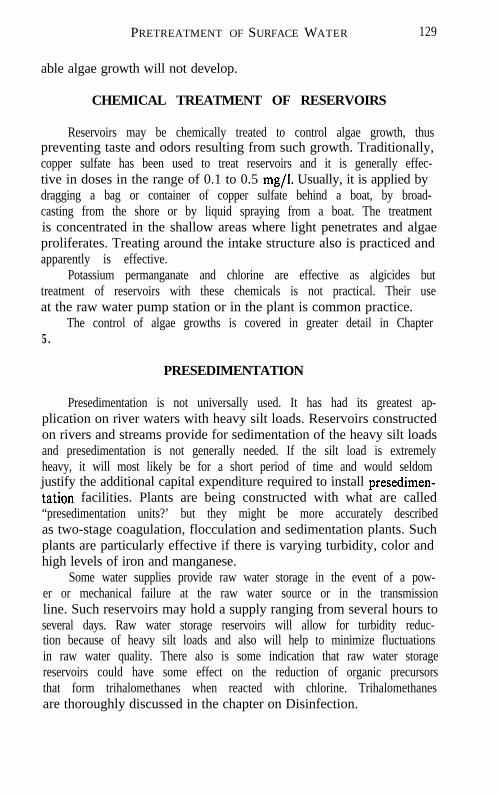
Presedimentation is not universally used. It has had its greatest ap-plication on river waters with heavy silt loads. Reservoirs constructedon rivers and streams provide for sedimentation of the heavy silt loadsand presedimentation is not generally needed. If the silt load is extremelyheavy, it will most likely be for a short period of time and would seldomjustify the additional capital expenditure required to install presedimen-tation facilities. Plants are being constructed with what are called“presedimentation units?’ but they might be more accurately describedas two-stage coagulation, flocculation and sedimentation plants. Suchplants are particularly effective if there is varying turbidity, color andhigh levels of iron and manganese.
Some water supplies provide raw water storage in the event of a pow-er or mechanical failure at the raw water source or in the transmissionline. Such reservoirs may hold a supply ranging from several hours toseveral days. Raw water storage reservoirs will allow for turbidity reduc-tion because of heavy silt loads and also will help to minimize fluctuationsin raw water quality. There also is some indication that raw water storagereservoirs could have some effect on the reduction of organic precursorsthat form trihalomethanes when reacted with chlorine. Trihalomethanesare thoroughly discussed in the chapter on Disinfection.

130 MANUAL OF WATER UTILITY OPERATIONS
AERATION
Aeration is a process wherebjr air and water are brought into inti-mate contact with each other for the purpose of transferring volatile sub-stances to or from the water. Oxygen is added to the water for the purposeof oxidizing iron, manganese, sulfides and possibly some organic materi-als. Volatile substances removed from the water include hydrogen sul-fide, carbon dioxide, methane, nitrogen and, to a limited degree, volatileorganics that may be responsible for taste and odor. Some industrial pol-lutants causing tastes and odors may be effectively removed by aeration.
Aeration has had its greatest application in the treatment of groundwaters in the removal of carbon dioxide, methane and hydrogen sulfideand in the oxidation of iron and manganese to allow for precipitationand/or filtration.
The use of aeration for surface waters, except in the destratificationof reservoirs, is frequently of questionable value although it is used bymany water supply systems. Most surface supplies have relatively lowconcentrations of carbon dioxide and hydrogen sulfide. The concentra-tions of iron and manganese may be subject to wide variations. The con-ventional treatment plant facilities, having coagulation, sedimentation,filtration and disinfection, may effectively remove these constituents inthe normal process of treatment. Iron and manganese will both be precip-itated in softening plants. Iron is readily removed in conventional coagu-lation and sedimentation processes but manganese must be oxidized ata high pH and may necessitate changes in the application points of someof the chemicals. Previously mentioned is the fact that most of the tasteand odor producing materials are not volatile and will not be removedby aeration. in some cases, however, improvement in taste and odor isattained, particularly if the taste results from a volatile organic pollutantdischarged to the stream or reservoir. Aeration has, in some cases, beendiscontinued, because of the corrosive characteristics of the oxygen-lad-en water. Thus, aeration is not a standard pretreatment process applica-ble to all surface waters. Studies should be made to determine what maybe accomplished by aeration of a particular water and the cost of aerationalso should be evaluated against other treatment methods that wouldachieve the same results.
Four basic types of aerators are used in the treatment of water: 1.spray aerators, 2. cascade, 3. multiple-tray, and 4. diffused air. The timeof contact between the water and the air and the ratio of the surface areato the volume of water are important factors in aerator design. Spraytype, multiple-tray and cascade aerators require a significant loss of head

PR E T R E A T M E N T O F SURFACE W ATER 1 3 1
while the diffused air energy requirement is that required to compressthe air and force it through small orifices to some distance below thesurface of the water. There is little or no loss of head associated withthe diffused air units.
Spray Aerators. - These aerators utilize fixed nozzles installedon a pipe distribution grid. The nozzles may discharge vertically or atan angle. The vertical nozzle gives the longest time of exposure of theparticles to air for a given head. The design of the nozzle is significantin achieving optimum dispersion of the water. Nozzles vary from thosehaving plain tips to those which impart a swirling motion to the water,The size, number and spacing of the nozzles depend upon the head andarea available for the aeration unit. The nozzles are generally 1 .O to 1.5inches in diameter to prevent problems with clogging. The dischargethrough each nozzle is 75 to 150 gpm at 10 psi. Spacing of the nozzlesvaries from 2 to 12 feet. The required area is 50 to 150 square feet permillion gallons per day of capacity. Spray aerators are efficient with re-spect to gas transfer. A disadvantage to such units is the large area re-quired and the impracticability of enclosing the units. The units cannotbe operated in freezing weather.
Cascade Aerators . - Cascade aerators are constructed in a varietyof configurations. The most common is a stair-step arrangement, gener-ally constructed of concrete, which spreads the water in a thin layer andallows it to fall from one level to another creating a turbulence. Otherdesigns involve shallow trays where the water is spread over the tray andflows in thin sheets over a shallow weir to a lower tray. Head requiredfor the cascade aerator is 30 to 10 feet. Area required is 35 to 85 squarefeet per million gallons per day capacity, with the normal area at approxi-mately 50 square feet. Time of contact can be increased by increasingthe number of steps.
Multiple-tray aerators. - Multiple-tray aerators consist of a seriesof trays equipped with slat, wire-mesh or perforated bottoms over whichthe water is distributed and falls from one tray to another to a collectionbasin. A coarse media, 6 inches in depth and 2 to 6 inches in diameteris used. The media may be coke, limestone, or other stone or ceramicballs. Three to nine trays are used with a spacing of 12 to 30 inches. Arearequired is 25 to 75 square feet per million gallons per day capacity butgenerally about 30 square feet. The trays are built with splash skirts.A typical multiple-tray aerator will have four trays with 18 inch spacingand an area of 30 square feet per million gallons per day. The coarsemedia used in the trays is most important in the oxidizing of iron andmanganese. The media becomes coated with a film that acts as a catalyst

132 MANUAL OF WATER UTILITY OPERATIONS
in oxidizing iron and manganese. Algae may become a problem that canbe controlled by shock chlorination or by treatment with copper sulfate.The exposure to air may be by natural ventilation or by forced-draft us-ing countercurrent flow. In countercurrent flow, air passes upwardthrough the trays with the water falling downward. Multiple-tray aera-tors may be housed or enclosed but the ventilation must not be obstruc-ted. Enclosure would allow for cold weather operation without the asso-ciated freezing problems. Multiple-tray aerators are approximately twotimes as efficient as cascade aerators. Contact may be increased by in-creasing the number of trays.
Diffused Air Aerators. - Diffused air aerators provide longer aer-ation time than the previously described types which involve falling fromone level to a lower one. Diffused air units are usually rectangular con-crete tanks in which the air is injected near the bottom through perforat-ed pipes or porous diffuser tubes or plates. The tanks are 9 to 15 feetdeep and 10 to 30 feet wide with the length governed by the detentiontime which ranges from 10 to 30 minutes. The diffusers are placed alongone side of the tank to provide a spiral flow which will create turbulenceand also will minimize short-circuiting of flow through the tank. Theair requirement is 0.01 to 0.15 cubic feet of air per gallon of water treat-ed. The blower discharge pressure will depend on the depth of the diffus-ers.
Aeration units should be constructed of corrosion-resistant materi-als.
Patented aerators are available using forced draft and diffused air.
CHEMICAL OXIDATION
Chemical oxidation of surface waters is directed toward a reductionor elimination of tastes and odors resulting from organic and inorganiccompounds or a combination thereof in the water. The chemical oxidantsalso are capable of oxidizing iron and manganese so that they may beprecipitated out. The chemicals used as oxidants are chlorine, potassiumpermanganate, ozone and chlorine dioxide. The oxidants, with the excep-tion of chlorine, also are expected to have some effect on the removalof organic precursors that may be responsible for the formation of triha-lomethanes when chlorine is added to the water (See Chapter 9 on Disin-fection). Taste and odor control is covered in depth in Chapter 5 andno effort is made in this discussion to be specific about taste and odorapplications.
Chlorine. - Chlorine has been the most widely used chemical oxi-

PRETREATMENT OF SURFACE WATER 1 3 3
dant until the promulgation of the regulations limiting trihalomethanes.Chlorine is most effective in the oxidation of some taste and odor produc-ing compounds but serves to intensify odors produced by others. Chlorinehas been applied at raw water pumping stations for the purpose of con-trolling growth in the line in addition to oxidizing taste and odor produc-ing compounds. Chlorine also has been applied in the rapid mix and, inmany plants, the total chlorination was accomplished at this point. Heavypre-chlorination has been discontinued in those plants that must meetthe trihalomethane regulations. Chlorine, however, continues to be usedfor shock treatment of lines and ahead of sedimentation as shock treat-ment for control of algae growth.
Potassium Permanganate. - Potassium permanganate is a veryversatile oxidant and is gaining in usage as an aid in solving taste andodor problems, particularly since the use of chlorine has been restricted.Potassium permanganate is known to be effective in improving tastesand odors caused by algae or industrial waste. Since potassium perman-ganate turns water purple and also leaves a residue of manganese dioxidein the water, it must be applied as a pretreatment procedure. The gener-ally accepted point of application is at the raw water pump station, whichallows time in the line for oxidation and for coagulation of the manganesedioxide. Potassium permanganate also may be added in a rapid mixahead of conventional coagulation, sedimentation and filtration plants.If the permanganate is used in conjunction with carbon, it should be ap-plied far enough ahead of the carbon application to allow completionof the reaction. Carbon will adsorb the potassium permanganate. Potas-sium permanganate also will oxidize iron and manganese but it is noteffective in the removal of trihalomethane precursors at the dosages nor-mally applied in water treatment practices, 1.5 mg/l or less.
Ozone . - Ozone has been used extensively in Europe and in Can-ada and is gaining greater acceptance in the United States for its abilityto oxidize tastes and odors and also as a disinfectant. It is effective alsoin color removal but not particularly effective in trihalomethane precur-sor reduction. Ozone must be generated on-site and the cost, as relatedto chlorine, has precluded extensive use. Again, the limitations on theuse of chlorine because of trihalomethane regulations has caused ozoneto be considered more favorably, both for taste and odor control and asan alternate disinfectant.
Chlorine dioxide . - Chlorine dioxide is formed by reacting sodiumchlorite and chlorine gas. It, too, must be generated on-site and also israther costly when related to the cost of chlorine. However, as in the caseof ozone, it is being investigated more thoroughly as a result of the limita-
134 MANUAL OF WATER UTILITY OPERATIONS
tions on chlorine usage. Chlorine dioxide is more chemically active thanchlorine and is a strong oxidizing agent. It is effective in taste and odorcontrol particularly in the destruction of chlorophenola. Chlorine dioxidedoes alter the trihalomethane precursors but the conditions under whichit has been used do not reflect typical water plant practices. It is moreappropriately considered as an alternate disinfectant.
ADSORPTION
Powdered Activated Carbon. - Powdered activated carbon ad-sorption of taste and odor producing substances is the most widely usedand is universally accepted as the most effective treatment procedurefor taste and odor control. It is a finely ground, insoluble black powderthat is easily fed through dry feed machines or as a slurry. Carbon maybe applied at any stage of treatment prior to filtration. Multiple pointsof application provide for a greater removal of tastes and odors; however,the usual point of application is in the rapid mix. Carbon may be appliedalso at the raw water pump station and may be applied to the filters.Five to fifteen mg/l is the normal range of dosage but extremely highdosages are sometimes used for short periods of time for severe taste andodor problems. Chlorine should not be applied with the activated carbonsince carbon will adsorb the chlorine reducing the effectiveness of both.Activated carbon also will adsorb potassium permanganate. Previouslymentioned was the possible use of carbon in conjunction with potassiumpermanganate. Potassium permanganate could be added at the raw wa-ter pump station if there were sufficient reaction time in the transmissionline and carbon could be added to the rapid mix. Removal of trihalometh-ane precursors with carbon could be accomplished but it appears thatdosages of 50 mg/l or higher would be required. Such dosages are noteconomical and cannot be considered as a practicable means of precursorremoval.
Granular Activated Carbon. - Granular activated carbon is usedin the form of carbon beds that are normally placed after the convention-al filtration system which would allow for applying the highest qualitywater to the granular activated carbon system. However, when the wateris low in turbidity, the beds may be used prior to coagulation, sedimenta-tion and filtration. Bottling plants and certain food processing plants usegranular carbon filters where a high quality water is necessary for qualitycontrol. Regeneration or reactivation of the granular activated carbonbed is necessary when the adsorption capacity of the bed is exhausted.A small percentage of the carbon is lost during the reactivation and must
P RETREATMENT OF S URFACE W ATER 135
be replaced. Granular activated carbon has been investigated in the re-moval of trihalomethane precursors from the raw water. It is initiallyquite effective for precursor removal but the rate of break-through isfairly high. Complete exhaustion of the bed does not occur. A steady-state develops where a constant percentage of precursors continues tobe removed, probably from biodegradation in the bed. Granular activat-ed carbon is not yet generally accepted as a pretreatment procedure.
S U M M A R Y
Pretreatment of raw water prior to the conventional water treatmentplant is accomplished by screening, aeration for destratification, chemi-cal treatment of reservoirs, presedimentation, aeration ahead of theplant, and chemical oxidation and adsorption. Probably the most signifi-cant procedure is the destratification or the prevention of stratificationof reservoirs by the application of diffused air to the bottom of the reser-voir. If stratification does not occur, many of the undesirable characteris-tics are eliminated thus eliminating the need for extensive use of someof the other pretreatment procedures. However, provisions should bemade for the other pretreatment procedures so that a totally acceptablewater might be delivered from the plant at all times.
BIBLIOGRAPHY
1. Wafer Treatment Plant Design, American Water Works Association, New York, 1969.2. MEADOWS, MICHAEL D., P. E., “Reservoir Management,” Paper presented to joint
session of the Texas and Southwest Sections, AWWA, Oklahoma City, Okla-homa, Oct. 1982.
3. American Water Works Association, Inc., Water Quality and Treatment, 3rd Edition,McGraw-Hill Book Co., 1971
4. TARAS, MICHAEL J., The Quest for Pure Water, Vol. 11, American Water WorksAssociation, 1981.
5. SYMONS, JAMES M., et al, Treatment Techniques for Controlling Trihalomethanesin Drinking Water, United States Environmental Protection Agency, Sept.1981.
6. James M. Montgomery Consulting Engineers, Inc., Water Treatment Principles andDesign, John Wiley and Sons, 1985.
‘IManual of Water Utility Operations, Seventh Edition, Texas Water Utilities Associa-tion, 1979.
CHAPTER 13
THE DISTRIBUTION SYSTEM
JAMES P. REAMES
Manager, West Cedar Creek Municipal Utility District
Possibly the most neglected and certainly the least visiblecomponent of a water utility is its distribution system. The dis-tribution system may be defined to be the water mains, valves,service lines and meter settings, booster stations, ground and ele-vated storage tanks, pressure regulators and other equipment re-quired to transport water from the well or purification plant to thecustomer.
The purpose of the distribution system and, therefore, the re-sponsibility of the distribution system operator is to deliver a suffi-cient volume at the required pressure to satisfy all of the waterneeds at any given time and place, while maintaining water quality.
In this chapter, the responsibilities of the water distributionsystem operator is organized into four major areas: A. Design, B.Construction, C. Operation, D. Maintenance.
A. Design includes planning to meet present and future de-mands by studying and analyzing population projections, percapita consumption, industrial expansion, area population densi-ties and fire requirements. These factors must then be translated tomain sizes from various sources of supply to the most remotepoints in the system. Proper selection of piping and other materialsmust take into account the pressure requirements and the corro-siveness of the soil and of the water. Other important considera-tions are location and depth of mains, sizing of service lines, andlocation and spacing of valves and fire hydrants. Provision ofbooster pumps, storage tanks, control valves and preparation ofspecifications complete the design discussions.
B. Construction includes selection of suppliers, quality testingand inspection of material received and installed, method of instal-
334

lation, pressure testing, cleanup, disinfection and bacteriologicaltesting and start-up.
C. Operation includes water quality sampling, cross connec-tion control, maintenance of maps and records, cleaning and flush-ing of mains, determining unaccounted-for-water, leak detection,system flow analysis, handling customer service line problems andhandling water quality problems.
D. Maintenance includes a consideration of the factors thatcontribute to pipe deterioration, the repair and replacement of ser-vice lines and the repair and preventive maintenance of valves, firehydrants and other appurtenances.
DESIGN OF DISTRIBUTION SYSTEM
Planning.-The distribution system should always be planned tomeet all of the present needs and oversized to some extent to meetfuture demands. The extent of over-design for the future will dependupon 1) the rate of growth, 2) the rate of increase in per capitaconsumption, 3) the availability of funds and the rate of interest, 4) therelationship of the economics of needs in other parts of the watersystem, and 5) the relative costs of alternates with reference to sizeand time. An example of the above factors follows:
If the rate of population increase and per capita consumptionindicates the need for having a 16-in main in 20 years while a12-in main would be adequate for the next five years, thefollowing facts must be available to make an intelligent deci-sion: the difference in the cost of the 12-in and the 16in pipe;whether that amount of additional funds is available; if avail-able, the’cost of interest for the period of time when the 16inwould be excess capacity; the cost of laying the additionalpipe in 20 years (when the route may be more highly im-proved.) Even though all of these factors, when consideredseparately, might indicate a positive warrant for the 16inmain, similar warrants for other segments of the system suchas supply, treatment or storage must be considered.
Population Projection.-Total population projections for a com-munity are generally based upon past growth. The population forcensus years is plotted and the “trend” is extended into the future. Itshould be noted that most cities grow more by proportion than by

330 MANUAL UC WA 1 L?K U 1 IL1 1Y Ul%KA 1 IUNS
number. As the size of a city increases, the number of additionalpeople increases each year. For example, the growth might be 20percent each 10 years rather than 2,000 people every 10 years. Citiesgrow for many reasons. A close scrutiny of the reasons should bemade as they apply to a particular city to detect changes in trends.
Per Capita Consumption.- Total water consumption, whendivided by the number of people served, gives consumption percapita-usually expressed in gallons per capita per day (gpcd).Obviously, this figure constitutes one of the most important factorsin distribution system design. The affluent 1950s and 1960s saw aphenomenal increase in average gpcd but this criterion of water usehas risen less sharply in the slowed economy and energy crunch ofthe 1970s. Per capita usage is still, however, increasing. Lawnirrigation is one of the major factors along with increasing indus-trial needs in many areas.
It is interesting to note that the range in annual average gpcd inmedium to large Texas cities is rather wide-120 to 215 gpcd inrecent studies. An equally important factor is gpcd on themaximum day. This ranges from 1.3 times average in areas ivhererainfall is plentiful and/or temperatures are mild to 2.5 times aver-age in the arid regions. Applying these factors to the averagesquoted above, you will note that a distribution system design mightbe required to transport anywhere from 160 to 540 gpcd on thehottest day of the year.
Industrial Expansion.-Providing for future industrial water in adistribution system design necessitates the prediction of general loca-tion and consumption. All other factors being equal, an industrialcustomer will locate on fairly inexpensive land which is or can be nearrailroad or major highway facilities, and properly zoned, away fromresidential areas, near adequate power, gas, sewer and waterfacilities. Most of these are found or should be found near existingindustries. When excess capacity for industry is built into a systemsome priority should be given to locating it in the area of existingindustry. This will allow for expansion of established industry, loca-tion of related industries, and an extra measure of fire protection andinsurance,benefits for what is often high-risk, high-value property.
Area Population Den&Y.-Most zoning plans provide for controlof open spaces, size of lots, number of stories above the ground, andnumber of families permitted in a structure. These controls have adirect relationship to the density of population and have some bearing

.I HE DISTRIBUTION SYSTEM 33.1
on the consumption of water in an area. If a master plan does not existwith zoning placing some control on these factors, they are stillpredictable to a reasonable extent and should be considered in design-ing the system.
Fire Requirements.- In addition to the customer demands, adistribution system must be capable of supplying sufficient waterfor fire fighting needs.
Many changes in standards have been made at the nationallevel. In Texas, however, the State Board of Insurance is respon-sible for establishing standards, grading water utilities and fire de-partments and setting fire insurance rates. Their requirements* forwater mains and fire hydrants in a “standard city” are:
Water MainsNot less than six inches in diameter, looped in residential
sections, and not less than eight inches in diameter in mercan-tile districts. All mains to be of cast iron of the pit cast and/orother approved type of machine cast pipe of bell and spigottype and/or other approved type joint fitting, and/or other ap-proved pipe materials or fittings. All material to be of standardquality and weights, and mains to be provided with properlyserviced valves. Detailed scaled maps to be maintained of dis-tribution systems showing all mains and fire hydrants togetherwith valve locations.
Fire HydrantsStandard three-way hydrants to have six-inch or larger
connection to mains with a minimum of five inch valve open-ing. Hydrants to be properly located so there will be a tirehydrant every 300-feet in the mercantile and industrial areas,and every 600-feet in residential areas, so that every buildingin the city limits will be within 500-feet of a standard city firehydrant. Hydrants to be maintained in good operating condi-tion and to be inspected, oiled, greased and flushed everythree months, and painted a distinctive color at least once ayear.
Many graphs, tables, formulas and other standards previouslypublished by the National Board of Fire Underwriters (NBFU) andthe American Insurance Association (AIA) are now obsolete. Thepublic protection functions formerly handled by these organiza-tions have been transferred to the Insurance Services Office (ISO).In 1974, IS0 adopted new standards with regard to fire flow andhydrant spacing requirements.
* “Key Rate Schedule for Grading Towns and Cities of Texas with Reference to theirFire Defenses and Physical Conditions,” available from State Board of Insurance,1110 San Jacinto, Austin, Texas, 78786.

Required fire flow varies from 500 gpm to 20,000 gpm, basedon a very complicated procedure that takes into account the build-ing area and height, the type of building construction, occupancy,automatic sprinkler protection (if provided) and the exposures tothe building. Details for calculation of the fire flow requirementsmay be found in the IS0 publication “Guide for Determination ofRequired Fire Flow”. *
Fire hydrant spacing is no longer stated in maximum distancebetween hydrants or maximum distance from a building to thenearest hydrant. Instead you are furnished a table of “standardhydrant distribition”. The table relates the average area per hy-drant in square feet to the required fire flow in gpm. As an example:If the required fire flow is 3ooO gpm, the average area per hydrantshould be 120,000 square feet. If 10,000 gpm is required then theaverage area per hydrant is reduced to 50,000 square feet. The IS0publication “Grading Schedule for Municipal Fire Protection”*provides tables and instructions for calculating fire hydrant spac-ing. The Fire Prevention and Engineering Bureau of Texas** isresponsible for applying the IS0 standards in Texas.
Main Sizes . -The mains in a distribution system must be care-fully sized to carry an adequate quantity of water and maihtain aminimum pressure to 30 to 40 psi for domestic use and 20 pdi duringmaximum fire flow. When no water is flowing, the pressure in thesystem is said to be “static”. Static pressure bears no relationshipto the size of the pipe. It is based only on elevation.
To understand the concept of static pressure; it is helRfu1 tovisualize a cubic foot of water. This cubic foot of water weighs62.35 pounds. The 12” x 12” bottom of the cube contains 144square inches. Thus, 62.35 pounds spread over 144 square inches is0.43 pound on each square inch (pounds per square inch or psi).The static pressure at the base of a 100 foot high elevated tank willthen be 100 x 0.43 or 43 psi. The pressure halfway up the tank willbe 50 x 0.43 or 21.5 psi. The static pressure downhill 100 feet lowerthan the base of the tank will be an additional 43 psi or 86 psi - nomatter how far away from the tank and no matter what size themain is.
* Available from ISO, 2 World Trade Center, New York, New York, 10048.**Fire Prevention and Engineering Bureau of Texas, 1320 Mercantile Security Build-
ing, Dallas, Texas 75201 (214) 747-0681.

FLOW OF WATER IN CAST IRON PIPE
8 0 0 05000
‘! 4 0 0 0a7 w o o6
52 0 0 0
4u
E 38
%WI .Eti 1000 =02 900%i 8 0 0 k
I!! 7 0 0 2y 0600(3 3
5 0 0.EP’ 1:
-5 04 0 0 F
0 ’ 8 2c5: .7 300 x‘5 .6 -6
72-’6 6 -6 0 -H-48:4 2 -
3 6 -
38 -2 6 -2 4 -2 2 -2 0 -1 8 -16- 5I4- ,g12- -50IO- *Es- %8 - 27- E.2!6- CI)S-
4 -
5-
2-
.04 7.os -06-
.08
0 . 1
.2
.3 -
. 4 -
- %3- 94- .E
20=
soi4 0 -507
300 -1
.7-I
. 8 -
. 9 -
I-.I -.2 -.3 -.4 -.5-.6 -.r -
:8- tJ2- 2-2
-2 - v)A - k.6 - t;.8 - 23-- c.2 - ‘3,.4 - -5.6 - 2.8 - 34=
S-
6:
(Reprinted by permission of Clow Corporation)
FIG. 13-1. - Flow of Water in Cast Iron Pipe

In distribution systems served by something other than ele-vated storage, the static water level at the pressure tank or thepump is imaginary. Changes in elevation within the system causechanges in static pressure exactly as described in the elevated tankexample.
When the system is in operation, the flow of water in the mainsis accompanied with loss of some of the static pressure (head) dueto friction. Figure 13-1 is a handy nomograph for determining therelationship between flow and head loss in various sizes of pipes.The nomograph contains four variables and will solve for any two ifa straight line is drawn connecting any other two.
For example:+Suppose you must select the pipe sizenecessary to carry a maximum flow of 2,000 gallons per min-ute a distance of one mile. Suppose further that the pipe origi-nates at the base of your elevated tank where the head is 100feet and terminates a mile away at an elevation 100 feet lower.You want to supply at least 20 psi residual at max flow. (SeeFigure 13.2)
The static pressure at the downstream end is 200 feet or 86psi. The residual must be 20 psi, so there is an allowable lossof 66 psi or 152 feet of head. The slope of the hydraulic gra-dient is therefore 152 feet in 5280 feet or about 29 feet perthousand.
On Figure 13-1, connect 2,000 gpm discharge and 29 feetper 1,000 feet head loss and you come up with a 9” pipeflowing over 9 feet per second. If you select a 10” pipe, youfind that it can supply the required discharge at a flow rate ofabout 8 feet per second and with a head loss of about 20 feetper thousand. A 10” will probably fill the bill if all customersalong the line are adequately served. Check the customer onthe hill very carefully to be sure that his residual pressure isadequate.
Appendix B lists Texas Department of Health regulations con-cerning main sizes.
The problem of sizing of mains increases in complexity as thesystem develops: loops, multiple loops, multiple sources of supplyand overhead storage tanks. Analysis of the system as a whole shouldbe a constant and recurring process. This subject is discussed in detailin “System Flow Analysis” discussion on operations. Fig. 13.3 is achart on equivalent pipe sizes and shows approximate relationship ofthe carrying capacities of various sizes of pipe. For example, a


-I-?/L IVIANUAL UP WA LDK U’I‘ILITY UPERATIONS
12-in main is the equivalent of 2.8 eight-inch mains or it would takethree eight-inch mains to carry the equivalent flow of one 1Zinchmain.
Materials Selection.-Considerable care should be exerted in theselection of materials for installation of water mains and service lines.They should meet the minimum requirements of AWWA standards.Besides the economics of the cost of replacement, other factors to beconsidered are local conditions such as soil, high and low temperatureranges, corrosive qualities of water, deterioration of future carryingcapacities, frequency of operation of valves and other appurtenancesand possible water hammer. Some cost analysis relative to installa-tion of various types of materials should be made before a finalselection of material is made.
If a sufficient number of qualified bidders is not available for thepreferred type of material, consideration should be given to request-ing bids on various types of material to get the best competitiveprices.
Each small system has a set ofconditions which must be met, andlarger systems may have a number of sets of conditions. The water-works operator today has a great advantage over his predecessorbecause of numerous materials from which to select. For mains thereis a choice between cast iron; ductile iron; reinforced concrete, steelcylinder type, prestressed or pretensioned; reinforced concrete, non-cylinder type, not prestressed; asbestos cement; and PVC. For serv-ice lines, he has a choice between copper, PVC, PB, PE, galvanizediron, black iron, steel, and brass. No one material is best for allapplications, and there is a set of conditions where almost any one ofthe materials described above might be preferred. Cast iron is theoldest and most common of the main materials. For purposes ofbookkeeping depreciation, a life expectancy of about one hundredyears is commonly used. This may be longer with reasonably goodsoil and water conditions. Lining cast iron pipe with cement mortarhas increased its carrying capacity. Reinforced concrete, steel cylin-der type, and asbestos cement pipe, are often estimated to have a use-ful life of approximately 50 years, as does steel or ductile iron pipewith proper protection and good environmental conditions. The usualclass of galvanized pipe without internal lining, in most waters andwithout wrapping or protection beyond the usual galvanizing, willhave a useful life of 15 to 25 years under most conditions. Plastic is arelatively recent development in pipe materials. The life expectancy

. . .
..
. . .
. . . . .
. .
. . . . . .
‘181 ‘6& ...‘WI ‘lop .‘.‘SI I ‘91f ....I01 ‘SLZ . .
2’88 ‘EPZ .‘.
P’9L ‘VIZ ...L’s9 ‘181 ‘..6’5s ‘VSI ‘L8LI’U ‘Of1 ‘ E E L1’6f '801 ‘609
O’ZEL’szE ’ O ZL’IIf’8
L ’ S9’E!‘Z0’1
.
t
::o”:‘66t‘lop
6’5s ‘91fO’Zf ‘ 1 8 16’22 'Of1
YSI Z’886 ’ 6 6’5sL ’ S O’ZE8’2 9'SI0'1 L'S
z I
... ...
... ...
... ...
... ...
... ...
f
:.. ...... ...... ...... ...
... ...
-0’1. ... . .-
. .. . .. . .. . .. .-
. .
. .. . .. .. .
-. .. . .... .
. .
. .
. .-
La
-
-P‘I0’1. . .. . .-. . .. . ... . .. . .-
. .. . .. . .. .-. . .. . .. . .
.-
.
. . .
-
iv
-
-1’2SI0’1. . .-. .. .. . .. ..-.. . .. .. . .. . .
. . .
.
. . .
. .-.... . .
-
9t
-
-Z’ff’Z9’10'1-. . .. . .. . .. . .. . .-. . .. .. . .. . .. . .-. . .. . .. . .. . .. . .-. .. .. .. ..-of
-
-o’zc6’229310’01-
L ’ S939’fZ’f8’2-
V’ZI'ZL'IS'I1'1-
WI. . .. . .. .. . .-. .. .. .. . .. . .-
ZI
-
-.. . .. . .. .- -
2.886’OL6’ssI ‘6PO’EP-
Z’LEO’ZEZ ’ L Z6’220’61-
YSIS'ZI6 ’ 6L ’ SI ‘P-
8’2L’l0’1
.-
P
-
L’II 9’SI 8'1Zf’8 Z’II YSIL’S 9’L 9'019’f 87 L’9
. .
. . .
. . .
. . .
. . .
. . .
. . .
. .
. . .
. . .
SOSZ’9f9’tZYSI
. . .
. . .
. . .Z’Li
wZ*9fOf
!‘s 6 ’ 8I’P t’9%‘I EY!‘I 8’z
3’1 9’1. . . E’I. . . 0’1. . . . . .. . . . . .
. . . . . .
. . . . . .
. . . . . .
. . . . . .
. . . . . .
. . . . . .: . . . . .. . . . . .. . . . . .. . . . . .
. . . . . .
. . . . . .
. . . . . .
. . . . . .
. . . . . .
ci 02
I'ZL’IE’I1’10’1-
. . .
. . .
. .
. . .
.
-. . ... .. . .. . .-, . .. . ...
8’1Z’ZL’lS’IE’I-
Z’I0’1. . .. . ..
8’fI'EP'Z1'26'1
6‘8 931 8’IZZ’L S’ZI SLIA’S 6 ’ 6 8’fI8’P L’8 I'ZIE’P 9’L 9'01
O’ZEL’szE’OZ8’LI9x1-
S’flL’II6 ’ 6f’8I’L-
SOS9’wO’ZE1'8Z9TZ-
E’IZf’819x1[‘El6’01-
L ’ S 6’893 Z ’ L9’f L ’ SI’Z Z’fS’I E’Z
PZzzoz618 1
9'1P'I2'1D'I. . .
9 ’ 9L’S8’PI'PP’f
Z’66’LL’9L’SL’P-
8’fI’fP’ZVI0’1
L I9 1S IP ICl
ZII I0 18L
. . .. . .
. . .
. . .. . .-
. . .
. .
. . .
. . .. . .
. . .
.
. . .
. . .
. .
9’1f’l0’1. . .. . .
8’1Z’ZL’I0’1. .
. . ,
. .. .
. .
. .
. . .
. . .
. .
.
. .
. . .
.
.
. . .
0'1. ... .
9 ’ 1D’I.. . ..
,
L
gl
-
9 1
-
P I 01 8 L 9
3dld d0 NOllVnbg

is not known, but without additional protection, plastic has definiteuses in highly corrosive soil and in areas where salt water encroach-ment is a problem. With most water qualities, the carrying capacity ofplastic pipe remains constantly high through the life of the pipe.
The plastic pipe industry has made great strides instandardization and quality control, two vital areas for any mate-rial in a water distribution system.
In writing specifications for a plastic pipe, pay close attentionto each detail such as thickness, diameter, (Standard DimensionRatio, SDR, is the relationship of diameter to thickness), raw ma-terials (including “fillers”), type of joint (can it be joined to pipeyou presently use?), joint material, special installation require-ments and depth of installation (can it stand the required earthload?). Plastic pipe for use in water distribution systems must bearthe seal of approval of the National Sanitation Foundation (NSF).
Rigid Pipe.-Rigid pipes such as cast iron and asbestos cementare designed to resist the internal pressure and the external loadsimultaneously since the stresses developed in the walls are additive.For cast iron pipe and asbestos cement pipe design, consult AWWAStandards Cl01 and C401, respectively.
Flexible and Semi-flexible Pipe.-The design of flexible pipe ismore complex since bending stresses are reduced by lateral soilreaction developed as pipe deflects under earth load plus anysuperimposed live loads and sides are pushed outward against sidefill. Flexible pipe, initially deflected by trench loads, is re-rounded byinternal pressure, which thereby reduces the stress of trench loads.Therefore, the two stresses are not additive and the pipe is designedto resist the internal pressure and then checked for deflection.
The sources of design procedures for various flexible andsemi-flexible pipe are to be found in Table 13- 1.
Embedment Design.-The design of any type pipe must be di-rectly related to embedment or laying condition specified, especiallyso with flexible pipe design. Presently each reference above cited forthe design of rigid, semi-flexible and flexible pipes uses variations of ageneral standard type of embedment. A suggested standardization isattached as Fig. 13.4. Variations can be utilized in areas wherecrushed stone is not available. For example, crushed shell mixed withsand and bentonite, if required, could be substituted in the coastalareas. Fig. 13.4 is particularly suitable for the Dallas area since most

TABLE 13-I. - Sources of Design Information of Various Pipe Materials*
Steel AWWA Manual M 11Ductile Iron AWWA Standard, Cl50Reinforced Concrete, Steel Cylinder, Not Prestressed AWWA Standard, C300Reinforced Concrete, Steel Cylinder, Prestressed AWWA Standard, C301Reinforced Concrete, Non-cylinder, Not Prestressed AWWA Standard, C302Reinforced Concrete, Steel Cylinder, Pretensioned AWWA Standard, C303Polyethylene Service AWWA Standard, C901Polyvinylchloride AWWA Standard, 000Cast I ron AWWA Standard, Cl01Cement Asbestos AWWA Standard, C401
* Obtainable from the American Water Works Association, Denver, Colorado.
installation is in a black clay or limestone formation. In areas wheregood sound earth or sandy loam is present, Embedment “D+” couldbe modified to use a flat trench bottom with bell holes excavated toallow the pipe to be evenly supported on the flat trench.
c .M.,
&ASS 6
FIG. 13-4. - Embedment for Water Conduits

Corrosion Protection.-In many areas of Texas the top soil con-sists of residual clays that contain dissolved metallic salts. These soilsin the presence of water, are corrosive to buried metal pipe due togalvanic action. The design and selection of material should take thisfactor into consideration. Galvanic corrosion is an electrochemicalreaction, similar to the action of adry cell battery. Basically the cell isan anode (-), a cathode (+), and an electrolyte (water with somedissolved metallic salts). A current flows in the electrolyte from theanode to the cathode carrying metallic ions from the anode intosolution. An anode can be formed in many ways: dissimilar metals,single metal with dissimilarities in composition or a single metalexposed to non-uniform environments, such as two different soils(clay and sand) in the backfill. The absence, or near absence, ofoxygen in a tight, heavy soil in the presence of soluble salts, results inthe growth of anaerobic bacteria, causing the development of gal-vanic cells also.
It is necessary to break up the continuity of flow in the gal-vanic cell to prevent corrosion. This can be done by 1) insulation orisolation of the structure from the electrolyte; 2) insulation of theanode from the cathode; or 3) conversion of the metal surfacecathodic to an external anode (cathodic protection).
A coating of coal-tar enamel and asbestos-felt or fibrous-glass-mat wrap as used on steel pipe partially insulates the struc-ture from the electrolyte. Cathodic protection is usually added.A loose sheath of polyethylene film of 8 mil thickness is effective toprotect cast or ductile iron, by isolating the pipe from direct con-tact with the soil.
Insulating gaskets, bolt sleeves and plastic washers will pre-vent the flow of galvanic or stray current at flanged connections ofbimetal components such as steel flanged outlets for a flangedvalve as used on steel cylinder type, reinforced concrete pressurepipe.
In a battery, the anode is corroded where the current leaves andenters the electrolyte; the&fore, if the entire structure can be madecathodic, there will be no corrosion. This can be done by bonding thejoints and by providing sacrificial anodes at intervals to act elec-trochemically, or a long life anode of a more noble metal can beenergized by an impressed current.
Main Location .-Standardization in locating mains with refer-ence to property lines is an absolute must. If the gas, electric,telephone and water utilities each have their own “zone” in astreet, conflicts are minimized and unnecessary excavationssearching for the main are practically eliminated.
Some factors to consider in establishing a standard are:
1. Standard locations of other underground utilities2. Type of street paving and highway restrictions3. Practice concerning laying mains and services ahead of pav-
ing4. Location and depth of borrow ditches and rainfall5. Topography and geometrical pattern of street layout6 . Likelihood of necessity for adjustment of grade or alignment
because of construction or reconstruction of storm drainagestructures, streets and highways and the policy of reim-bursement of cost of adjustment
7. Soil conditions8 . Prediction of frequency and difficulty of repair of leaks due to
location.
There must, of course, be exceptions to every standard locationrule. If a standard is followed about 75 percent of the time, theproblems of recording and constantly referring to the records isgreatly reduced by crews in the field when making taps, repairs andlocating valves. An often debated question is location of mains inresidential alleys. Local preference and soil conditions play thegreatest roles in alley usage. If alleys are kept open and have con-stant vehicular traffic, they can make good water main locations. Ifthe trend in a community is toward closing alleys or abandoningthem “except as utility easements,” problems of access to repairleaks and read metem will very likely develop. Mains should bedeep enough to avoid freezing and damage from operations of roadmaintenance machinery. They should be below the flow line orabove the high-water line at crossings of drainage courses. Loca-tions paralleling and in the bed of drainage courses or in roadwayborrow ditches are not recommended since washouts and pipe fail-ures can occur if extensive counter measures are not taken. Wherepossible, large volume mains should be kept at a safe distance from
large buildings. As vehicular traffic increases and streets becomewider, more attention should be given to the relative cost andbenefit of running separate service mains on each side of thethoroughfare.
Sizing of Service Lines.-Pressure in the range of 35 to 60 psiprovides a generally accepted level of service to the customer. Theservice line should be sized so that the pressure at the meter duringperiods of heavy usage is in this range if at all possible. Very lowpressure at the customer’s tap will surely result in complaints andill will. Many appliances such as dishwashers and automatic wash-ing machines have their filling cycles controlled by time clocks andwill not perform properly unless the pressure is adequate. Someappliances will not operate at all if the pressure falls below theminimum established by the manufacturer.
The ever increasing popularity of lawn irrigation and waterusing home appliances dictate that a minimum standard for serviceline sizing be established for residential properties.
For example, in a single family resideptial area with homeshaving one bath and lawn irrigation using one hose and sprin-kler, a 3/4-in service line will usually suffice if pressure is above30 psi on peak consumption days. If pressure gets between 20and 30 occasionally, a one-inch service should be installed.
House lines should be one size larger than the service linewhen the main pressure is less than 60 psi.
Such standards serve to protect future residents of the premisesserved. Most homes in areas with pressures of less than 60 psi will, attimes, suffer low volume with a 3/4-in service if the following factorsare present to any extent: 1) lot wider than 50 ft and needs irrigation,2) two or more baths, 3) two or more water using appliances, 4) two ormore outside faucets, and 5) evaporative type air conditioning orwater-cooled condenser. All of these factors represent an instantdemand for water and are becoming more common every day.
Each service should be designed specifically to meet the needsfor industrial, commercial, residential lawn sprinkler systems, com-mercial fire sprinkler systems, and apartment house customers. Thecustomer generally expects assistance from the utility operator in allbut tie sprinkler and large lawn sprinkler systems above 2-in serviceline size.

1 Hh lJIS I KlkiU l.lWN 3YSl-EM J4Y
To design the service properly, the following information will beneeded:
1. Pressure at the main (normal and minimum)2. Length of service from main to the meter3. Quantity of water required through the meter4. The residual pressure needed when furnishing the required
quantity of water.
The design of the plumbing and yard piping would of necessityprecede or be coordinated with the service design. Computed frictionlosses for various components of a 3/4-in through l-in service linesand 5/8-in through 2-in meters are given in Table 13-3.
Most 3/4-in through 2-in service line conditions can be estimatedfrom this table developed from actual tests conducted by D. R.Taylor in the Baton Rouge, La. water system. Following is an exam-ple of the application of Table 13-2:
Assume a customer desires to install a sprinkler system with ademand for 40 gpm at a residual pressure of 35 psi, the serviceline is 40 feet long, and the static main pressure is 55 psi. Theallowable friction loss through the service line and meter iscomputed by subtracting 35 psi from 55 psi. Allowing 6 to 8gpm for household consumption while the sprinkler system isin operation, the total demand is found to be 46 to 48 gpm. Inthe table for two parallel lengths of one-inch copper and aone-inch meter if the 20-psi pressure loss column is traced to apoint opposite 40 ft of length, indication is that the customercould expect to obtain about 49 gpm. From footnote 1, thecustomer could expect about the same amount of water if a 1l/4-in copper or 1 l/4-in galvanized pipe were substituted forthe two parallel lengths of l-in copper. This would be thepreferable arrangement from a maintenance standpoint. Alsoin many rate schedules, it would be more economical to thecustomer.
These values change slightly with the use of various fittings andcomponents. See also Water Meters-Selection, Installation, Test-ing and Maintenance, AWWA Manual M6, Chapter 3, obtainablefrom the American Water Works Association, 6666 Quincy Ave.,Denver, Colo. 80235.
Line Valves.-Line valves should be located so that a break in themain would not necessitate shutting off more than about 500 ft of themain in the high value district and about 800 ft in other areas. Someattention to the relationship of valves and fire hydrant locations is
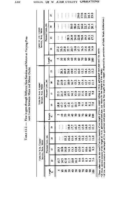
MANUAL UP- W ATEK UTILITY UPEKATIONS
. . . . . .9909c?9. . . . .. . . . . :szzza

TABLE 13-2. - (Continued)
Length.
ft.
5 31.0 38.5 45.0 49.5 5
1 0 29.5 37.0 43.5 48.0 1 0
2 0 28.5 35.5 42.0 46.5 20
3 0 26.0 32.5 39.0 42.9 3 0
40 23.8 29.7 35.7 3 9 . 1 40
5 0 22.0 27.5 33.0 36.2 5 0
60 20.5 25.7 30.7 33.8 60
7 0 19.1 24.0 28.8 32.0 7 0
8 0 1 8 . 0 22.7 27.2 30.0 8 0
90 17.1 21.6 26.0 28.6 90
1 0 0 16.3 20.6 24.7 27.3 1 0 0
Table for Single Length Table for Two Parallel Table for 2 Parallel Lengths
of l-in. Copper Service Lengths of l-in. Copper l-in. Copper Service.
I-in. Meter Service. I-in. Meler’ IM-in. Meter’
IO
Pressure Loss, psi.
I5 20 25
tLength.
ft.
T Pressure Loss. psi.
IO I5 20 25
42 . . .
41 . . .
39 48
36 44
34 42
32 39
31 38
30 37
29 36
28 34
27 33
. . .
. . .
. . .
. . .
49
46
4 5
4 3
4 2
40
3 9
. . . 5 60 74 8 7 98
. . . 1 0 57 71 8 3 9 4
. . . 20 51 64 7 5 8 5
. . . 30 47 59 69 78
. . . 40 43 54 6 3 7 2
. . . 50 40 50 59 67
50 60 38 47 5 5 6 3
48 70 36 45 5 3 60
4 7 80 34 43 50 5 7
4 5 90 33 41 48 5 5
4 4 loo 31 39 46 5 2
Length,ft.
T Pressure Loss. psi.
IO I5 20 25

k
TABLE 13-2. - (Continued)
Length, - -
f t . IO I5
5
1 02 030405060708090
1 0 0
- -
70 8768 846 3 7859 7 356 7053 6651 6 34 9 604 7 584 5 564 4 5 4
Table for 3 Parallel Lcnahsof l-in. Copper Service,
IH-in. Meter
T
-
Pressulr Loss. psi.
-
-
a3
-
. . .
989 1868 1777 37 1686 564-
2 5
. . .
. . .
. . .
979 2878 380777472
FLength.
n .
T5
10203 0405060708090
100
Table for Two, Three and Four Parallel Lengths of I-in. Copper Service. 2-k Mete?
-IO
-I S
- -
78 9 7
7 3 9 16 3 7 856 7050 6246 5843 5 340 503 8 473 6 4 53 5 43- -
2 Lengths I-in. Coppr
Pressure Loss. psi.
3 Lengths I-in. Copper 4 Lengths l-in. Coppr
Pressure Loss, psi. Pressure Loss, psi.
M 2 5 IO 1 5
1 1 3 1 2 8 110 1361 0 6 1 2 0 98 1 2 2
9 1 103 86 1 0 88 1 92 78 9 77 3 82 7 1 8867 76 66 8262 70 62 775 8 66 5 8 7 25 5 62 5 5 6852 59 52 6550 57 50 62
,,/,.1 5 6 . . . 1 1 5143 160 1061 2 6 1 4 2 1031 1 3 128 951 0 3 116 89% 108 8389 101 778 4 95 7480 90 7076 86 6773 82 65
15
1 5 21 4 41 2 81 1 81111 0 39692878 380
2 0
. . .
. . .
1 5 01 3 81 2 91 2 01 1 21 0 71029794
2 5
. . .
. . .
. . .
1 5 61 4 61361 2 71211151 1 0106

desirable to assure a wet hydrant in another section in the event of ashut-out. The difference of a few feet in locating a line valve on oneside or the other of a fire hydrant lead may seriously affect the fireprotection potential of a large area.
A uniform pattern for location of valves with reference to prop-erty lines makes them easier to find. An example is:
On an extension of the property line with preference to thenorth and west legs of the intersection.
Valves in larger mains will bear wider spacing, especially if firehydrants are on smaller lateral mains which are looped. Gate valves16-in and larger usually have bypasses to aid in closing against adifferential in head. The bypass valve should be opened before ashut-down in the larger valves to prevent surge or shock loads. If boththe main line and bypass valves are not located in a manhole or vault,a pattern for setting and clear marking of valve boxes is desirable; forexample, main line valve on north and west with bypass on the southand east and with red spray paint on the inside of the main valve box.
All fire hydrants regardless of location should be valved on thefire hydrant lead.
When future side lateral lines can be located and sized accu-rately, it is good economy to set a connecting fitting and valve. Theconnection can then be made simply and without an interruption ofservice.
Double disc, non-rising stem, gate valves have in the past beenstandard for water distribution system line valves. Butterfly valveswith rubber seats have increased in usage in recent years, especiallyin larger sizes.
Fire Hydrants.-Spacing of fire hydrants was discussed earlier.Hydrants are normally set in street intersections, but this should notbe the controlling factor. They should be well back of the curb,especially in the radius, to avoid being hit by the overhang of vehicles.A hydrant located across the street is often of more practical value fora particular risk such as a high building, a lumber yard, etc. A hydrant“in the front door” may not be usable because of falling debris orintense heat. The American Water Works Association SpecificationC502* is the standard for Fire Hydrants for Ordinary Water Works
* These may be obtained from the American Water Works Associat ion, Denver.
Colorado.

354 MANUAL OF WATER UTILITY UPERATIONS
Sen~ice and covers size, materials, design, painting and workman-ship. Appendix B of that specification is for a standard color codingfor fire hydrants based on flow. As automobile traffic increases, moresystems are using the “traffic-model” or “break-away” hydrant. Thestem and barrel break off near the ground line under impact.
Special Valves.-Air relief valves are used at high points in thesystem to release entrapped air. They are generally very small, rela-tive to the size of main, since most of the air, after a break, is releasedthrough manipulation of fire hydrants. Larger mains, depending onthe terrain and size, are often constructed with air-vacuum reliefvalves on high spots. These valves allow air to enter the main after abreak, as the main drains, and release the entrapped air as the mainis refilled. Air-vacuum relief valves also release entrapped air thataccumulates in normal service. This can cause loss in carryingcapacity.
Pressure regulating valves are used to reduce excess pressure toa normal range. In hilly areas if a large area has excess pressure,usually above 100 psi, the system may be isolated by installing suchvalves in the main or mains. If the area is small and sparsely popu-lated, better service may result from the installation of small pressureregulators on each house service. Altitude valves are similar in con-struction to pressure regulators and are used to shut off the flow ofwater into an overhead storage tank at a preset level to avoidoverflow.
Check valves are used to allow flow of water in one directiononly. There are both horizontal and vertical check valves. A hori-zontal check will not operate properly on a vertical run of pipe, andvice versa. They are most commonly used on the discharge side ofpumps, and also on service lines to multistory buildings and onbuildings with more than one service. They are sometimes used toallow flow into but not out of a booster area.
Booster Stations and Tanks.-Booster stations are most oftenused to increase water pressure in areas with high elevations. Theyare, however, used less frequently to increase pressure or volume atremote points on a system where friction loss has reduced the pres-sure and volume below the required minimum. In these instances,they are substitutes for laying larger mains or elevated storage.
A booster station taking suction directly from the feeder main isnot acceptable waterworks practice. A pressure equalizing reservoirshould be constructed at a ground elevation that would preventwasted head loss. A pump station should also be constructed to takesuction from the reservoir.

Specifications.- It is essential that standards for materials andinstallation be available for use with all force account and contractualwork. These standards, or specifications, are the written instructionsto supplement the drawings in order to set forth the complete techni-cal requirements of the work. They define the quality of the materialand workmanship desired by the owner and serve as a standard andguide for the contractor or builder. In general, the drawings show thedesign of what is to be done; whereas the specifications state how it isto be accomplished and results to be obtained. Normally thespecifications are given greater legal strength than the drawings andmost contracts so state. Due to new ideas and concepts in materials,soil technology and the resulting improvements in the techniques ofinstallation of water distribution mains, it is necessary that periodic,in depth reviews be made of the specifications that are in use forconstruction.
CONSTRUCTION
Preconstruction Planning.-Prior to the start of construction, thejob should be planned properly for the specific location. Such plan-ning should include: location of other utility lines; staking of line andgrade; determination of material quantities; the acquisition of allnecessary material; planning and arranging for the necessary tools,equipment, and personnel to effect the installation; obtaining neces-sary barricades, signs and safety equipment for safety on and aroundjob; obtaining proper easements and permits from property ownersand governmental agencies; gaining clearance with budget authority;making preliminary contact with adjoining property owners; andarranging to provide temporary service if it becomes necessary tointerrupt utility services.
Material Testing and Inspection.-The extent to which materialinspection and testing should be pursued depends upon previousexperience with the materials being used, past experience with themanufacturer’s or supplier’s materials, and the quantity of materialsreceived on a given order. In the case of extremely large quantities ofmaterials delivered over a long period of time, testing at themanufacturer’s establishment by an employee of the buyer may bedesirable and most economical. In instances of serious doubt or pastfailures of materials, grab samples may be taken and sent to privatetesting laboratories for tests of strength, chemical and metallurgicalquality.
Installation of Mains.-Excavation of the pipe trench should be
made efficiently, but particular attention should be paid to manyfactors. The bottom should be smooth and free of rocks or other hardobjects which would cause a bridge in the pipe support with bearingon sharp, hard points. This may result in a future failure when settle-ment occurs in the pipe trench. The trench should not normally beopened very far ahead of the pipe laying crew and particular careshould be exerted in,closing as much of the ditch as possible beforeleaving the job for the night. The barrel of the pipe should lie directlyon the bottom of the trench and the trench excavated a few additionalinches in depth at the joints of the pipe if a flat bottom trench ispermissible. When the trench is very deep or wide, greater attentionshould be paid to the material and method of backfill. Granularmaterial carefully worked under the pipe, such as Class B or CEmbedment, Fig. 13-4, will give better support to the pipe whenbackfill material is loaded on top and begins to consolidate around thepipe. “Walking in” with the feet in stages, tamping with mechanicaldevices, and water saturation help in the proper consolidation ofmaterial around the pipe. This helps avoid later settlement of thesurface of the ground or pavement.
The transportation of the pipe and fittings to the job begins withproper storage of materials. They should be stored in a place wheredamage to the materials would be minimal, and reloading could bedone with the greatest ease and safety. When material is delivered tothe job site, it should be unloaded as near to the point of use aspossible. Pushing or rolling material from the truck onto a hardsurface often damages the material by impact on sharp objects or hardpavement. The installation of water mains is largely a job of materialhandling. If the job is approached on this basis, with sufficient plan-ning for equipment and personnel, the cost might be kept to aminimum. The dirt is transported from the ditch to the spoil bank; thepipe is transported to the job and transported again into the ditch; andthe spoil bank is returned to backfill. The equipment and personnelfor each of these four phases of the basic operation must be amatched set so that each one continues in operation without waitingfor the other to catch up. The watertight integrity of the water line de-pends upon the properjoining of the pipe in strict compliance with theapplicable specifications. A thorough and complete installationspecification for the type of pipe to be installed is essential and shouldbe provided as part of the design.
All bends, terminal points, and extended appendages not an-chored positively to the pipe line should be adequately blocked sincepressures tend to “blow off’ non-anchored ending points. Blow-off

1 HE UISTRIBUTION SYSTEM 357
valves in low areas and on the ends of pipes should be provided forcleaning of a pipe by flushing. Blow-off valves should be sized suchthat a minimum of one foot per second velocity can be obtained inthe main.
In connecting the new pipe to existing pipe, careful considerationshould be given to a tapping sleeve and valve connection as opposedto a “wet connection.” A wet connection often involves more thanjust the cost of fittings and their installation. The “shut-out” mustnormally be done during night hours to avoid customer inconveni-ence, thereby necessitating overtime. A certain amount of risk isalways involved in damage to equipment during emptying and refillingthe system. Customer inconvenience is caused by interruption ofservice, muddy water and air in the system immediately after refilling.Another factor to contend with is the creation of a wet and oftendangerous condition at the connection due to the concentration ofwater at that point in making the cut for the wet connection.
Care should be taken throughout construction to minimize con-tamination from introduction of foreign material into the pipe. Eachjoint of pipe should be visually inspected and a “swab” pulledthrough it just before lowering it into the ditch. The end should becapped off in some manner before leaving the job to prevent dirt andanimals entering the pipe while unattended.
Installation of Services.-The service line installation shouldoriginate with a properly executed order, defining in particular thegeographic location and size. Field errors in sizing of the service lineor location on the wrong lot, or wrong place on the lot, results inunnecessary expense or bad public relations for the city. It may causeunnecessary expense for the customer by his laying a longer orbadly-located service line.
Every utility should have a well-defined set of regulations con-cerning service lines, including: general location; who is permitted tomake the connection at the main; how far the utility’s portion of theservice line extends (to the curb line, 10 ft beyond the curb line, backof the sidewalk, to the property line, etc.); metering of services;multiple meters on a service; method of payment for service line;variations in cost for variable sizes and locations; components to beused in the usual service; and the selection of materials for eachcomponent part of the service. The usual persons permitted to makeservice connections to the main are utility personnel. The methodconsists of tapping the main with a tapping machine designed fordrilling, tapping, and inserting a corporation cock under pressure.The usual location on the main is just above the center (looking at the
end of the pipe, the tap would be made at about 2 o’clock or 10o’clock). On small-pipe main lines with inflexible service line mater-ial, the service might be installed in the same plane, horizontally withthe main. If flexible material is used, it is desirable that it not bestretched tightly, but at least some weave or loop effect is left in thepipe to allow for ditch settlement and temperature expansion andcontraction.
The service line should be laid deep enough to avoid mainte-nance machinery, effects of cold weather, and excessive vibrationfrom roadway traffic. In most areas of Texas, a depth of 2% to 41% ft issufficient and desirable. The ditch should be excavated as narrowly aspossible and backfill material should be well consolidated.
The clean-up should be carefully done since a portion of the workis usually in the street and on or near someone’s lawn or business.Sidewalk and street paving cuts should be replaced or repaired assoon as practical.
Finally, a portion of the job in the field should be the creation of aproper record of the location and material going into the service andmarking it on the curb.
Disinfection and Bacteriological Testing.-All water delivered tocustomers must be free of contamination. Even though installationhas been done carefully, it is necessary to flush and disinfect all newmains and services. A thorough-fhtshing should be done prior todisinfection and testing. It is done through fire hydrants, blow-offvalves and blow offs at the end of mains. It has the effect of removingparticles of dirt and debris left in the main during construction andgives some disinfection by slightly chlorinated water coming into themain from the system.
Disinfection according to AWWA Standard C-601* and StateDepartment of Health standards requires the use of chlorine andpermits the use of calcium hypochlorite, chlorinated lime, chlorinegas, or liquid chlorine. The main is loaded with water containingapproximately 40 to 50 mg/l of chlorine and allowed to stand over aperiod of about 24 hours..After 24 hours, there should be a well-defined residual remaining in the pipe. (See Chapter 12.) A sub-sequent test of a bacteriological sample taken after the pipe isrefilled with system water must show no coliforrn organisms pre-sent before the utility customers are permitted to use the water.
A number of methods for introducing the chlorine solution intothe pipe for the 24-hour retention are available. The most commonsystem used for short extensions of pipe is to place a small quantity ofsodium hypochlorite in each joint. A more common and effective

system, however, is to pump a solution of chlorine and water into themain through a corporation cock on the upstream end near the valvewhere water is introduced into the system. The valve is opened andwater introduced slowly as a quantity of the chlorine solution ispumped into the main at the proper rate to achieve a fairly equaldistribution of the heavily chlorinated water throughout the newlyconstructed main.
Pressure Testing-In all installations of mains of major length, athorough hydrostatic and’leakage test should be made under pres-sure. The main is filled and air eliminated. Water is pumped into thesection to be tested under pressure at least 50 percent greater than thenormal operating pressure. The pressure is maintained at least onehour and the line checked for leakage. A method for leak testing oncast iron or ductile iron pipe is described in AWWA SpecificationC600* which states that -during a period of at least two hours noinstallation will be accepted until the leakage is less than the numberof gallons per hour as determined by the formula for mechanical jointsand push-on joints:
L =NDfi3700
in which L equals the allowable leakage in gallons per hour; N is thenumber of joints in the length of pipe line tested; B is the’nominaldiameter of the pipe in inches; and P is the average test pressureduring the leakage test in psi gauge. Other standards are available fordifferent types of pipe; for example, AWWA C603* stipulates theleakage allowable for asbestos-cement pipe. On large diameter steelpipe with double lap welded joints, a hydrostatic test is not necessaryif each joint is air-tested as described in AWWA Manual M ll.*
Clean-Up and Start-Up.-Construction is not completed until allclean-up has been effected and the new facility placed in service.Clean-up should include the physical removal of all papers, excessand broken material, excess spoil bank, felled trees, trash, etc. Sodand shrubs that have been destroyed in the process need replacement.Sidewalks, streets, curb and gutter, steps, walls, other utility serv-ices, driveways and borrow ditches should be restored to theiroriginal condition.
In wetting a new main it is important to fill the main slowly andbleed off all air at high places. Unusual differentials in pressure areexerted on the pipeline in the filling process, especially if air is presentto be compressed causing bouncing of pressures in the main. Checks* Obtainable f rom the American Water Works Associat ion, Denver , Colorado.
36U MANUAL OF WATER UTILITY OPERATIONS
should be made of the ends of mains, fie hydrants, bends and otherfittings where blocking has been necessary to see that minor leakshave not started by the imbalance of pressure. If air relief valves arenot located on the main, it may be desirable to return in a day or twoand check hydrants in high places to bleed offthe last remnants of air.
OPERATION
Bacteriological Sampling in Operations.-The first considerationof the waterworks operator must always be the safety of the waterwhich he provides his customers. The most important place fortesting is in the distribution system at the point of use. Since water-borne diseases transmitted by bacteria are the greatest safetyhazards, bacteriological tests must be run at regular and frequentintervals.
The Safe Drinking Water Act, passed by the U.S. Congress in1974, has placed new requirements on the number of samples ofwater analyzed for bacteriological quality each month as well asthe maximum contaminant levels allowable and the consequencesof exceeding these levels. New Texas Department of Health regu-lations (see Appendix A) are similar to Federal regulations exceptthat the minimum number of samples per month for any utility istwo.
Cross Connection Control.-The utility operator, in cooperationwith the health department, plumbing inspector, and local plumbers,must constantly be on guard to correct cross connections andbackflow connections. They are defined as follows:
A cross connection is any physical connection or arrangement ofpipes between two otherwise separate water supply systems, one ofwhich contains potable water and the other water of unknown orquestionable safety, whereby water may flow from one system to theother, the direction of flow depending upon the pressure differentialbetween the two systems.
An example of a cross connection is a customer’s pri-vate well interconnected with the utility system’s waterwhen both are connected to the house plumbing system withthe intention of using them alternately for lawn irrigation or house-hold use. To the utility operator the water well would produce waterof an unknown or questionable safety; thus we have a cross connec-tion between the two systems, separated only by a valve. The TexasState Department of Health regulations require an air gap betweenthe two systems, which would prohibit, in effect, alternate usage.
Backflow connection is any arrangement whereby the flow ofwater or other liquid into the distribution system of a potable watersupply can occur from any source other than the intended one. Abackflow connection, on the other hand, might be illustrated by abarrel containing insecticide in the back yard of a residence beingfilled by a garden hose immersed in the insecticide barrel. Since thegarden hose is connected to the city system from the house plumbing,a failure in the utility system causing a reduction or complete loss ofpressure, could result in the insecticides being siphoned back into thesystem.
Constant surveillance and inspection (particularly of businessfacilities such as hospitals, mortuaries, boilers, respirators, auto-matic car wash installations, etc.) are necessary to prevent cross con-nections and backflow connections. American Water Works Asso-ciation Manual M-14* entitled Backflow Prevenrion And Cross-Connection Control describes in detail many situations and types ofequipment to look for in backflow prevention.
True cross connection control is achieved onfy through the useof an air gap separation and this is the only device that is recog-nized by the Texas Department of Health. Other devices in wideuse are: vacuum breakers, both atmospheric and pressure types;double check valve assemblies; and reduced pressure principle de-vices. These devices have an important application for protectingthe people in a building from drinking contaminated water from across connection in the same building.
The public distribution system should, however, never be di-rectly connected to a contaminated source. Total isolation via theair gap is the only sure preventive measure.
Maps and Records.-The minimum record of a distribution sys-tem contains maps showing the location of all mains, main size, andthe location in detail of every line valve. Other parts of a good mapand record system include distribution system maps of various scalesin detail, street intersection drawings showing water utilities andother utility locations, valve location tie-in records, operation andmaintenance records of valves, hydrant maintenance and operationrecords, service records, an evaluation record of all capital invest-ment in the system, reports of leak surveys, leak repair records, andcustomer complaints and investigation reports. A good system ofstandard maps and records is given in detail in AWWA Manual M-8,Water Distribution Training Course.* Once a system is devised, an
* Obtainable from the American Water Works Association, Denver, Colorado.
362 MANUAL OF WATER UTlLl’IY UPCKAI IUNb
accompanying system of reporting changes must be worked out toimplement the system and keep it up-to-date. The system of report-ing and recording of changes must be constantly followed if anaccurate system of records is to be maintained.
Cleaning and Flushing of Mains.-Various kinds of water andtypes of pipe cause different conditions in the distribution systemwhich might be improved by cleaning and flushing the pipe. Theresults of flow tests and visual inspections may indicate a buildupof tuberculation or deposits in the pipe. These are most often foundin unlined cast iron or steel pipe. Their removal requires mechani-cal cleaning and may be prevented only by lining of the pipe orfurther chemical treating of the water. Another type of deposit is aslime growth in the pipe. Iron and manganese deposits are mostfrequent. They are more predominant in cement-lined cast iron,concrete pipelines and asbestos-cement pipelines. High-velocityflushing can help this condition but will not cure it for a long periodof time. The only long-range remedy is further treatment of thewater prior to introduction to the distribution system. Heavy dos-age of chlorine ahead of sedimentation at the plant will tend toprecipitate and settle out the iron which might be deposited in themains, but potassium permanganate or some other chemical will benecessary to effect the same treatment for manganese.
Some companies have successfully lined in place cast iron pipewith cement. This process, though expensive, may be more economi-cal than abandonment, particularly in downtown business areas withconcrete pavement from building to building.
The most common and almost universal reason for flushing is thereduction of sediment in the pipeline. In most distribution systems, itis necessary to flush out turbidity deposits which have settled out inthe pipe when the velocity of the water is not sufficient to keep them insuspension. For example, dead-end lines with insufficient usage re-quire periodic flushing until the dead end can be circulated. It isgenerally desirable to do such flushing at high velocities and on aschedule which will meet the needs of the particular areas where theproblems occur. It is desirable to flush the whole system once or twicea year. Full-scale flushing should be carefully planned and carriedout, beginning at the upstream end of the system and going to theouter edges. Because of the unusual turbidity created by flushing andthe wetting of many streets, it is generally desirable that this type ofoperation be done in the evening after the heavy water consumptionperiod is over.
Accounting for Water.- Accounting for water consists of care-

fully comparing water pumpage into the system with the meteredsales and other water uses out of the system. The difference betweenthe flow-in and flow-out is unaccounted for water. These losses areusually caused by under-registration of meters or dead meters, hiddenleakage, and unauthorized or unreported uses. Attention must begiven to the.differences in period of time for which records are kept.Customer readings for a whole system may be two weeks to six weeksdelayed from the master-meter readings at the source of supply intothe system. As a rule, one month’s delay with a whole year’s recordwill give an accurate indication of the accounted for water. Theunaccounted for water should not exceed 20 to 25 percent and will, ina well-managed system, be about 5 to 10 percent.
Leak Detection.-There are three basic methods of leak detec-tion surveying: (1) visual inspection of drainage ways during dryseasons to detect unusual flows of water in creeks, storm sewers, andsanitary sewers; (2) measurement method of closing off a portion ofthe system, with a single source of supply and measuring all water into‘the area for a short period of time and reading of all meters ofcustomers in the area for the same period; (3) use of sound detectiondevices, which may range from a simple rod, driven into the ground orplaced against a pipe or appurtenance, to modern electronic deviceswhich pick up minute sounds and vibrations from the soil at a consid-erable distance from the leak or use.
An aggressive program of testing meters and immediate re-placement of obviously slow or non-registering meters (especially onlarge meters for customers with very high consumption) will result inincreased revenue and a marked reduction of unaccounted for waterin most instances.
System Flow Analysis.-A constant analysis of the capabilities ofa system to carry water is necessary to proper operation. The sim-plest system is the observation of pressure and measured flow at agiven point under a given set of conditions and recording thesefindings for future comparison under approximately the same condi-tions. A hydrant-flow test is another method of testing a small portionof a system. This involves the measurement of residual pressures inthe system with fire hydrants flowing and measuring the quantity offlow. This method is used by the Insurance Services Officeand the Texas Board of Insurance. It is used frequently by fireinsurance companies in the vicinity of a high-risk client. Attention toand recording of results made by others can give some indication ofthe continuation of the system’s ability to carry water.
Flow analysis of the whole system in determining pipe sizes for

JO4 MANUAL UF W AI‘EK U.llLll Y UPEKAI IUNS
new extensions and feeder mains is highly desirable. Any accuratesystem-wide flow analysis must begin with detailed tests forcoefficients of friction in various types of pipe of various ages in orderthat accurate estimates might be applied in this important factor ofsystem analysis. A careful check ofall valves must be made to be surethat none have been inadvertently left closed. In a small .systemwithout many complications of branch lines and loops, the analysiscan be made by manual calculations or graphical solution. In widersystems, however, the electrical network analyzer as developed byMcElroy, or the Hardy Cross system of network analysis is used.The recent advent of computers in distribution system analysis, par-ticularly as used with the Hardy Cross system, has made systemanalysis by this method more practical. This method involvesmathematical trial and error calculations and the accuracy dependsupon the number of trials for a given loop.
As the cost of construction of pipelines increases, the propersizing and location becomes more important and system networkanalysis to make these determinations becomes an economic neces-sity. Many engineering tirms offer system tlow analysis service.Communities undergoing rapid expansion have a particular need of asystem flow analysis, periodically updated to include new portions ofthe system.
Customer Service Line Problems.-Areas with wide variations intemperature, humidity, and rainfall have more problems with cus-tomer relations because of service lines than other areas. The mostcommon complaint is a steady reduction in water pressure; another isthe difficulty of getting water at one tap when the lawn sprinkler orother high volume use-tap is on. The utility operator knows that thislatter complaint is a volume problem. The customer, however, relatesthem to water pressure and will seldom understand the hydraulicsinvolved. In most instances, a systematic, on-premise investigation(if possible in the presence of the customer) is the desired procedure,with detailed record made of the results of the pressure and volumetests.
The investigation should commence with a thorough inspec-tion of the meter setting and the valves in the customer’s yard todetermine whether any of the valves, stops or cut-offs are partiallyclosed. The serviceman should then ask the customer to show himexactly where and how the poor pressure is exhibited. These twosimple steps can save many hours hunting for a problem that doesnot exist.
Next, the serviceman should install a test stand at the meter

1 Ht: IJIS I KlBU.1 IUN 3YS’I’EM 363
location. The apparatus will enable him to measure pressure onboth sides of the meter and will allow him to discharge water toatmosphere while observing flow and pressure. The usual proce-dure would involve flowing various fixtures and hydrants on thecustomer’s premises while observing flow rate and pressures at themeter. Using a stop watch or sweep second hand on his wristwatch and observing the water meter, the number of gallons perminute can be determined.
The service line should then be allowed to flow to atmosphere,and the flow and pressures are again observed. The results of thistest can be compared with Table 15-2 to determine if problemsexist on the service line. Manufacturers’ head loss tables should beconsulted to see if the head loss through the meter is excessive.Any deficiencies in the service line and/or meter should bepromptly corrected.
Problems of corrosion, line stoppage, or other inadequateplumbing facilities on the customer’s premises are fairly easilydemonstrated by this procedure. If the customer observes the testand the problem is on his plumbing, it is generally not too difficultto convince him.
Thorough records must be kept on all of the various pressureand flow readings taken.
Some of the common problems on the utility side of the meterare: sand or trash stopping up the strainer of the meter, a kink in thecopper or lead service line, corrosion in a galvanized service line, apartially closed corporation cock (though this is rare), corrosion in afitting used in the meter setting, or combinations of these. Some ofthemore common problems on the customer’s premises are: a heavilycorroded galvanized service line going to the house, a partially closedprivate cut-off, water pipes too small in the house for appliances onthe line, stopped up strainers on appliances or aerating and mixingfaucets, corrosion or chemical deposits in automatic small checkvalves at the base of swing faucets (in kitchen sinks having a dish-spray hose at the side) or combinations of these.
Red Water, Black Water, and Sandy Water.-The most commoncause of water discoloration is increased velocity and agitation ofsediment in the bottom of mains. This commonly occurs after breaks,fires, fire hydrant tests, minor flushing of mains, and during the firstfew heavy consumption days in the summer (in areas where irrigationis common). Anything short of full-scale flushing of the system mayresult only in transferring the problem from one area to another. Theonly common cures are periodic, regular flushing and allowance of

time to let the foreign material resettle in the bottom of the pipe. Asudden outbreak of complaints of this nature may be the first warningto the operator of an unreported break in a major pipeline.
Black water which has a rotten egg smell is often encountered bythe operator in flushing hydrants or dead ends of mains. This blackcolor and obnoxious odor is often the result of septic organic materialin the main. It seldom gets to the customer, but may (especially ondead-end mains) affect the customer’s service by the creation of gaswhich is dissolved in the water and comes to the customer as taste andodor with no discoloration. If the customer complains of black water,it may be sediment, but if the system has been observed to have blackdiscoloration on concrete or concrete lined pipe, the black water isprobably caused by manganese deposits inside the pipe.
Red water is often caused by iron bacteria or iron from unlinedsteel or cast iron pipe. Red spots on clothes are caused by the abovedescribed red water as well as quantities of dissolved iron in excess of0.3 mg/l. Occasionally, a red water or iron-specked complaint (espe-cially if isolated) may be the result of an unlined hot water heater oriron pipe on the customer’s premises which has not been flushed outrecently. Do not use chlorine bleach to remove red spots or it will setthe stain.
Sandy water is most often caused by changes in velocity anddirection of flow in the system. It occurs very often when large, newmains are placed in operation, causing wide shifts in the flow patternin the system. In most instances, the foreign matter is not silica sandbut is calcium carbonate scale removed from the pipe walls by areversed flow. Repeated large-scale flushing is often necessary overa period of months to eliminate this problem, since sand or calciumcarbonate scale seems to be carried from the whole system into a fewisolated areas where it causes stopped up meters, “sand in the bath-tub” and many industrial water problems.
Customer On-Premises Problems.-There have recently beenchanges in attitudes and expectation of services by both customersand operators of water utilities. There has been slowly emerging aconcept of complete water service. Most operators no longer stop atthe property line but make extensive investigations on the customers’premises. Such inve,stigations as a search for a known leak, waterquality deterioration source, closed valve or “pressure loss” arecommon, even though utility participation in the on-premises correc-tive measures is almost non-existent. The on-premises investigationis justified by the attitude that the utility must show the customer hisproblem in order to prove that the responsibility for the condition

complained of is not in the facilities of the utility. This attitudecontributes greatly to good public relations.
MAINTENANCE
Pipe Deterioration.-Constant attention should be paid to thecondition of system piping and even material in storage because ofdeterioration by the elements, chemical reaction, and electrolysis.Exterior surfaces of metal pipe (especially iron and steel) are subjectto oxidation or rusting by ground water, particularly in tidal areas.Some water supplies are similarly detrimental to pipe interiors ifthe pipe is not protected. Acid soil and “hot soil”, stray electricalcurrents and galvanic action are other metal pipe hazards. Con-crete and cement asbestos pipe are subject to deterioration by acidconditions in the soil or the water. Some plastics are subject todeterioration or noticeable changes in physical characteristics bytemperature in both extremes, and from prolonged exposure tothe ultraviolet rays of the sun.
Fortunately, protection procedures or methods of installationare available to offset most of the problems related above, but theoperator must be aware of the potential problems and neededprotective measures.
Corrosive Water.-The greatest cause of corrosion inside pipeis probably low pH. All corrosion occurs at the surface of the pipe.Corrosion inside water pipe is almost always chemical or elec-trochemical in nature. Materials in the pipe must be relatively inertto the chemicals in the water supply in order to avoid corrosion orthe pipe must be lined with inert material. Non-metallic materialssuch as cement, asbestos and coal-tar products are most commonpipe protection materials.
Corrosive Soil.-Corrosive soil, corrosive ground water andstray currents all have similar effects on pipe exteriors. Galvanicaction as well as chemical reactions may result from various typesof soil and ground water when they are brought into contact or innear proximity with the pipe. Stray electrical currents passing backand forth between the pipe and the surrounding soil have similardetrimental effects. Corrective measures are to 1) replace the pipewith one of inert material, 2) coat or wrap the pipe with chemicallyinert materials, 3) coat or wrap the pipe with material which willinsulate electrically, 4) make joints of materials which will provideelectrical insulation, and 5) use cathodic protection and sacrificial

anodes. In some cases of corrosive soil, the use of selected,hauled-in mateial for bedding and backfill is economical. In someareas it may be possible for improper grounding of appliances onwater pipe to cause pipe deterioration at places where the currentleaves the pipe.
Dissimilar Metals .-Galvanic action set up by the use of dif-ferent metals attached to each other, such as a valve bolted to asteel flanged outlet and copper’ pipe directly threaded to a steelpipe, are built-in weak spots in a system. In many instances auseful life of 20 years for two separate metals is shortened to threeor four years by direct connection of the two metals. An insulatinggasket and insulation bolts or a short fitting or section of a dielec-tric material will destroy the galvanic cell.
Repairing Main Breaks.- Every water main break is anemergency. The degree of the emergency is more directly related tothe size of the pipe rather than the quantity ofthe leak. A small leak ona large pipeline in soft soil may become a major emergency before thevalves can be closed and the repair effected. A responsible personfamiliar with the system should be called to make the decision aboutwaiting until morning to repair a small leak discovered at night. Whenquestions arise about the source ofunexplained running water, simplechemical tests such as pH or residual chlorine may settle the questionin many areas. As a general rule, the first step in repairing a mainbreak is finding all the valves necessary to stop the flow of water at thebreak and closing all of them but one (unless excessive propertydamage is occurring from the tlow of water at the break). By permit-ting a limited flow of water, the exact location of the break can bedetermined as the pipe is being exposed by the digging equipment. Itis usually desirable to excavate the area just below the pipe on bothsides of the pipe with a sump-hole of some depth below the pipe onone side. After the flow of water is stopped, a ditch pump can be usedto lower the water level in the excavated area below the bottom of thepipe, thereby keeping ditch water from entering the pipe. Under nocircumstances should the flow of water be stopped and a fire hydrantopened at a lower elevation in order to drain the water from the ditchthrough the water pipeline. This practice, though convenient for theutility operator, could result in serious contamination of the system.Once the pipe is exposed, the operator can easily determine themethod of repair and the supplies needed to effect the repair. Theequipment for making emergency repairs should always be ready,including excavating equipment, ditch pumps, pipe cutters, air com-pressors and pavement breakers, emergency lighting equipment, as
well as a complete stock of repair materials such as repair clamps,sleeves, extra pipe and fittings of all sizes in the system, all types ofhand tools and barricades with warning lights. All precautions takenduring construction such as disinfection, testing, backfilling, andclean-up should be taken in making a major repair. A sufficientnumber of trained personnel should be available at all times to handlethe more commonly recurring emergency repairs.
If three or more breaks occur in 1000 feet of main, it may bemore economical to replace the main with a less corrosive material(if the breaks are caused by corrosion) or a material protected fromcorrosion.
An article by J. H. Stacha in the May, 1978, issue of JournalAWWA entitled “Criteria for Pipeline Replacement”* outlines acomprehensive method for comparing replacement cost to pro-jected cost of maintenance. The author concludes that replacementis justified if the projected cost of maintenance over the next 20years exceeds the cost of debt service on the capital required toreplace the main.
Joint Leak.-The most common type ofjoint leak found in manysystems is on caulked joints, using sulfur compound caulking mater-ial. This material has often caused deterioration of the adjoining castiron pipe sufficiently to allow water to bypass the caulking material.This is usually repaired by installing a bell-joint clamp. Where thistype of joint material was used, and the pipe is covered by a pavedstreet, it may be most economical to repair a large number of jointssimultaneously in anticipation of future leaks on every joint. Minorleaks on many types of joints might be effectively repaired by caulk-ing leadwool into the void. Many joint leaks can be repaired withoutkilling the main. If leaks develop in a mechanical bolted joint, usuallydue to corrosion, the bolts should be replaced with low-alloy steelbolts or bolts that are properly protected from corrosion.
Broken Service Lines.-When a copper or lead service is brokenbetween the curb stop and main, the flow of water is often stopped bypinching or flattening the pipe on the main side of the break. If themain line is not under pavement and the corporation is easily accessi-ble, this procedure would not, of course, be followed. Special toolsfor pinching and re-opening copper pipe are used by many operators.If such a tool is not available and the operator wishes not to dig out thecorporation, a special flaring tool with a hole through it must be usedin flaring the copper for installing the necessary coupling to make the
*Reprint #0003-150X/78/0500-256 available from AWWA - Denver, Colorado.

repair under pressure. When a corporation cock is pulled out of thepipe, or the pipeline has broken vertically where the corporationscrews into the main, a repair sleeve or clamp with a tapped hole forreplacement of the corporation cock in its original position may savethe operator time and expense. This method saves the operator fromexcavating a new area to the side of the break, making a new tap andsplicing the service line pipe for the additional length to reach the newtap location.
Replacing Service Lines.-In some instances where a service lineis leaking under pavement with the main located on one side of thestreet and the meter on the other, replacement of the service line ismore economical than repair by a pavement cut. If the length of theline is relatively short, the diameter of the replacement pipe is thesame or less than the original, and the soil conditions are not tight, thenew pipe may be connected to the old pipe on one side of the streetand the old pipe pulled out of its location from the other side of thestreet. Simultaneously, the new pipe is pulled into the same location.The same general system may be used in replacing badly corrodedservice line if the tensile strength of the pipe is sufficient. It may bepossible to renovate deteriorated service lines by the insertion of aplastic tube.
Maintenance of Valves.-All valves in a system should be in-spected regularly. Most direct-drive buried gate valves should beinspected about once a year. Very large valves and valves withenclosed gear boxes should be inspected more often. Each inspectionshould include operation of the valve to a completely closed position,re-opening to about one-quarter and re-closing until the valve seatsproperly and easily in the closed position. This insures the removal ofrust from the moving and seated parts and keeps the valve in condi-tion to perform its function of stopping the flow of water in anemergency. The valve box should be cleaned out sufficiently topermit the ready placement of the valve key on the operating nut.On valves with conventional packing, kerosene poured down thevalve stem prior to operation will lubricate the stem against thepacking gland and soften the packing, thereby reducing leakagethrough the packing gland. It is desirable to maintain a record ofvalve operation and maintenance.
If a valve stem turns freely and is obviously not causing move-ment of the gate, immediate steps should be taken to determinewhether the valve is broken in an open or closed position. A largevalve broken in the closed position should be repaired on anemergency basis.

Maintenance of Fire Hydrants.-Fire hydrants should be in-spected once or twice a year. Constant surveillance of their condi-tion, operation and use should be maintained. Each hydrant should beopened fully upon formal inspection. The operation should always bewith the proper hydrant wrench. After each operation of a fire hy-drant, the caps should not be replaced until a thorough check is madeof the water’level in the barrel to insure that the valve is completelyclosed and the water is draining from the barrel through the drain holein the bottom. Moving parts of thethydrants should be lubricatedaccording to the manufacturer’s specifications. Weeds and grassshould be kept cleared for better visibility of the hydrant. It should bekept attractively painted with the proper color for the color code.Caps should be tighter than hand tight and promptly replaced whenremoved by vandals. Fire hydrants should be high enough above theground so that a fireman can, in an emergency, open the steamerconnection with a valve wrench without the necessity of digging intothe ground or removing the wrench.
Each hydrant should be flow-tested periodically and the re-sults of the test along with the necessary maintenance recorded inthe hydrant maintenance record.
A complete stock of repair parts for each type of hydrant in thesystem should be maintained and one or more complete replacementhydrants kept on a standby basis.
Maintenance of Appurtenances .-In large water systems wherethe responsibility is departmentalized, the operator ofthe distributionsystem should carefully consider the areas of his responsibility, inorder to plan the stocking of repair parts, proper inspection andsurveillance offacilities. The responsibility of maintenance should beconsidered on such appurtenances as booster stations, plant yardpiping, system check valves, elevated storage altitude valves,cathodic protection systems, and remote pressure recording devices.
Rules and Regulations.-The reader is urged to read carefullyall of the stipulations regarding water distribution (Section .OOS) ofthe “Rules and Regulations for Public Water Supply Systems”,published by the Texas Department of Health. This can be found inAppendix B of this Manual.
ACKNOWLEDGMENTS
The author gratefully acknowledges the work of R. E. Morris, Jr.and Robert H. Hayes, the previous authors of this chapter, and D. R.Taylor, who developed Table 13-2.

CHAPTER 14
PUMPS AND MEASUREMENT OF PUMPS
ASA E. HUNT, P.E. & CLEMENT M. MILLER
Manyfacturers’ Agents, Dallas, Texas
Pumps are the usual source of energy necessary for the trans-portation of water from one location to another through various sizesand types of pipe. The only exception may be where the source ofenergy is supplied entirely by gravity. Modern water works operatorsmust therefore be familiar with pumps, pump characteristics, pumpoperation and maintenance. There are three general requirements ofpump and motor combinations. These requirements are (1) reliability(2) adequacy and (3) economy. Reliability is generally obtained by in-stalling in duplicate the very best equipment available and by the useof an auxiliary power source. Adequacy is obtained by securingliberal sizes of pumping equipment. Economy can be achieved bytaking into account the life and depreciation, first cost, standbycharges, interest and operating cost.
A careful analysis should always be made before selecting thesize (capacity) and type of pump for a given purpose. A pump mayoperate although it is not the proper size or type for the specific re-quirements, but under such conditions its efficiency will be low andoperating cost will be high. Frequently an investigation will indicatethat many existing pumps are costly because of inefficiency orobsolescence; economy would dictate their immediate replacement.
Certain factors should be considered in the selection of pumpsand the construction of pumping plants. Certain criteria of theTexas State Fire Insurance Commission and National Board ofFire Underwriters should be investigated and their requirementsshould be met in the pump station. Some of their requirerlentsmay be: dual power supply for reliability; pumps housed in fire-proof structures; effective operation and maintenance. Secondarypower sources to supplement electric motor drives are usuallynatural gas, diesel or gasoline fueled engines.
The minimum pumping capacity recommended is to be sufficient
312

PUMPS A N D PUMP ME A S U R E M E N T 313
to meet maximum domestic demand combined with fire flow at therequired pressure. The exact requirements of the State Fire In-surance Commission should be investigated and its recommenda-tions followed.
Factors Affecting Pump Selection.-Prior to specifying a pumpthe following must be determined: (1) maximum capacity that maybe demanded of the installation, (2) the nature of the water, its tem-perature, pH, dissolved chemicals, gases and suspended matter, andif such suspended matter is abrasive, (3) the average, maximum andminimum discharge head conditions, including the size of the pipeand whether the pipe system is closed or open and with llxed eleva-tion (system curves should be developed), (4) the average pressureor suction lift, the diameter and length of suction lines, (5) theservice, whether constant or intermittent, (6) type of power availablefor pump drive, (7) space available for the pumps, (8) the weight ofpumps and power units. Pumps and their drivers should be theproducts of a reputable manufacturer. Their performance undervarying conditions should be known and guaranteed by the suppliers.The availability of parts and service should always be a factor in one’sspecifications.
PUMP NOMENCLATURE
The Hydraulic Institute uses comparable interchangeable terms.
Proper Name
Impeller
Casing
Impeller ring*
Casing ring*
Also Called-Remarks
Propeller, runner, wheel. (Propeller is sti l l proper for thespecific group called axial flow pumps.)
Case, housing shell, volute. (When horizontal split, the twopieces are called upper half and lower half casing with thesuction and discharge nozzles in the lower half. Whenvertically split , the portion having the discharge nozzleand impeller chamber is called the casing.)
Impeller wearing ring. (Ring is mounted on impeller androtates with it.)
Casing wearing ring, seal ring. (Ring is mounted in casing.With end suction pumps, one of these is usually cal ledeither a suction cover ring or stufhng box cover ring andis mounted in position for which it is named.)
* The clearance between these two pieces is quite close. Both are replaceablein order to renew this clearance when the rings wear. Some smaller pumps have onlycasing rings.
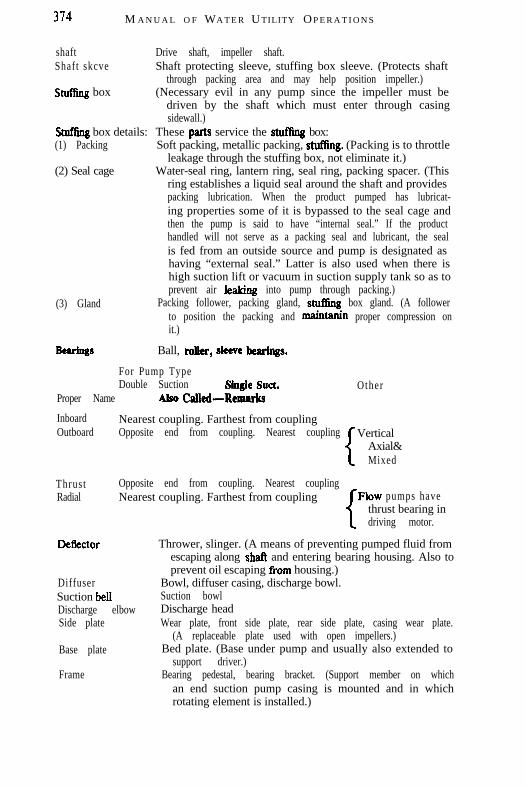
374 M A N U A L O F WA T E R U TILITY O P E R A T I O N S
shaft Drive shaft, impeller shaft.Shaft skcve Shaft protecting sleeve, stuffing box sleeve. (Protects shaft
through packing area and may help position impeller.)snIfEng box (Necessary evil in any pump since the impeller must be
driven by the shaft which must enter through casingsidewall.)
Wffing box details: These parts service the stutling box:(1) Packing Soft packing, metallic packing, stuffing. (Packing is to throttle
leakage through the stuffing box, not eliminate it.)(2) Seal cage Water-seal ring, lantern ring, seal ring, packing spacer. (This
ring establishes a liquid seal around the shaft and providespacking lubrication. When the product pumped has lubricat-ing properties some of it is bypassed to the seal cage andthen the pump is said to have “internal seal.” If the producthandled will not serve as a packing seal and lubricant, the sealis fed from an outside source and pump is designated ashaving “external seal.” Latter is also used when there ishigh suction lift or vacuum in suction supply tank so as toprevent air kaking into pump through packing.)
(3) Gland Packing follower, packing gland, stufiing box gland. (A followerto position the packing and maintanin proper compression onit.)
Btprings Ball, Idler, skew hear&s.
For Pump TypeDouble Suction SingIe Suet. Other
Proper Name AISO Calkd-Remarks
Inboard Nearest coupling. Farthest from couplingOutboard Opposite end from coupling. Nearest coupling
1
VerticalAxial&Mixed
Thrust Opposite end from coupling. Nearest couplingRadial Nearest coupling. Farthest from coupling rFlow pumps have
Deflector
DiffuserSuction bellDischarge elbowSide plate
Base plate
Frame
I thrust bearing indriving motor.
Thrower, slinger. (A means of preventing pumped fluid fromescaping along shaft and entering bearing housing. Also toprevent oil escaping tiom housing.)
Bowl, diffuser casing, discharge bowl.Suction bowlDischarge headWear plate, front side plate, rear side plate, casing wear plate.
(A replaceable plate used with open impellers.)Bed plate. (Base under pump and usually also extended to
support driver.)Bearing pedestal, bearing bracket. (Support member on which
an end suction pump casing is mounted and in whichrotating element is installed.)

PUMPS A N D PUMP MEASUREMEN T 315
Pump ConstructionTCCmiNJlogy
Standard
Fitted
All
Usually cast iron casing, bronze fitted which includes impeller,rings, sleeves, bushings, seal cages and glands. Shafts carbonsteel although sometimes stainless if pump is built withoutsleeves .
Fitted pumps will have all parts except the shaft and the casingof the required special material. If you don’t want specialmaterial used for the balance of the pump parts be specificfor each individual item. Do not use the term “trim” as thisis not specifically delined and you will get a fitted pumpregardless.
A pump specified as being all stainless steel or all anythingshould have every part of the fittings plus the shaft and thecasing of the specified special material. This means that allparts in contact with the liquid (called “wetted parts”) willbe of the special material.
JWNDAMENTAL CONSIDERATIONS
Head.-The pressure at any point in a liquid can be thought of asbeing caused by a vertical column of the liquid which, due to itsweight, exerts a pressure equal to the pressure at the point in ques-tion. The height of this column is called the “static head” and is ex-pressed in terms of feet of liquid.
The static head corresponding to any specific pressure is de-pendent upon the weight of the liquid according to the followingformula:
Head in Feet =Pressure in psi x 2.31
Specific Gravity
A centrifugal pump imparts velocity to a liquid. This velocityenergy is then transformed largely into pressure energy as the liquidleaves the pump. Therefore, the head developed is approximatelyequal to the velocity energy at the periphery of the impeller. This rela-tionship is expressed by the following:
Where H = Total head developed in feet.v = Velocity at periphery of impeller in feet per sec.g = 32.2 ft/sec.2
We can predict the approximate head of any centrifugal pump by
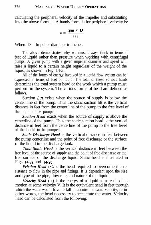
3 7 6 MANUAL OF WATER UTILITY OPERATIONS
calculating the peripheral velocity of the impeller and substitutinginto the above formula. A handy formula for peripheral velocity is:
rpmxDv =
2 2 9
Where D = Impeller diameter in inches.
The above demonstrates why we must always think in terms offeet of liquid rather than pressure when working with centrifugalpumps. A given pump with a given impeller diameter and speed willraise a liquid to a certain height regardless of the weight of theliquid, as shown in Fig. 14-3.
All of the forms of energy involved in a liquid flow system can beexpressed in terms of feet of liquid. The total of these various headsdetermines the total system head or the work which a pump mustperform in the system. The various forms of head are defined asfollows.
Suction L$ft exists when the source of supply is below thecenter line of the pump. Thus the static suction lift is the verticaldistance in feet from the center line of the pump to the free level ofthe liquid to be pumped.
Suction Head exists when the source of supply is above thecenterline of the pump. Thus the static suction head is the verticaldistance in feet from the centerline of the pump to the free levelof the liquid to be pumped.
Static Discharge Head is the vertical distance in feet betweenthe pump centerline and the point of free discharge or the surfaceof the liquid in the discharge tank.
Total Static Head is the vertical distance in feet between thefree level of the source of supply and the point of free discharge or thefree surface of the discharge liquid. Static head is illustrated inFigs. 14-2a and ‘14-2b.
Friction Head (ht) is the head required to overcome the re-sistance to flow in the pipe and fittings. It is dependent upon the sizeand type of the pipe, flow rate, and nature of the liquid.
Velocity Head (h,) is the energy of a liquid as a result of itsmotion at some velocity V. It is the equivalent head in feet throughwhich the water would have to fall to acquire the same velocity, or inother words, the head necessary to accelerate the water. Velocityhead can be calculated from the following:
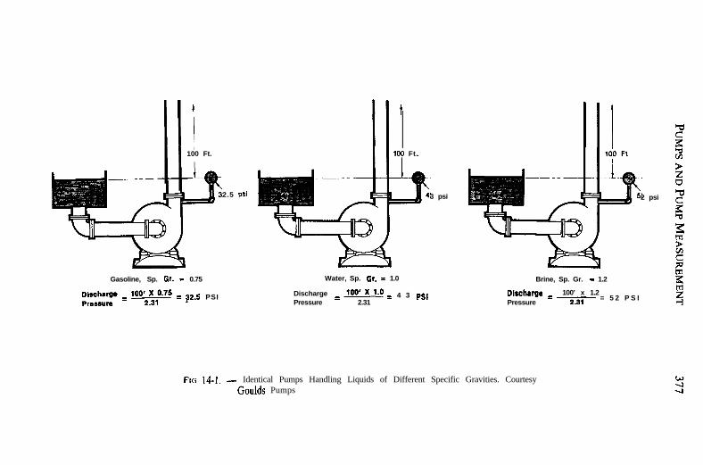
]100 Ft.
I
2.5 psi
Gasoline, Sp. Or. = 0.75
;rsu’:l’ = ‘w = Q2.5 PSI
Water, Sp. Or. = 1.0 Brine, Sp. Gr. - 1.2
100 Ft.
3 psi
Discharge = 100’ = 4 3 p.QPressure 2.31
2 psi
Dircherge 100’ x 1.2Pressure
= 2.31 = 5 2 P S I
FIG 14-I. - Identical Pumps Handling Liquids of Different Specific Gravities. CourtesyGoulds Pumps

378 MANUAL OF WATER UTILITY OPERATIONS
h, = !!!
3s
Where g = 32.2 ft/secgV = liquid velocity in feet per second.
The velocity head is usually insignificant and can be ignored in mosthigh head systems. However, it can be a large factor and must be con-sidered in low head systems.
Pressure Head must be considered when a pumping systemeither begins or terminates in a tank which is under some pressureother than atmospheric. The pressure in such a tank must first beconverted to feet of liquid. A vacuum in the suction tank or a positivepressure in the discharge tank must be added to the system head,whereas a positive pressure in the suction tank or vacuum in the dis-charge tank would be subtracted. The following is a handy formulafor converting inches of mercury (Hg) vacuum into feet of liquid.
’ ISTATIC
DISCHG.
HEAD
FIG. 14-2a. - Suction Lift Showing Static Heads in a Pumping System with the PumpLocated Above the Suction Tank (Static Suction Head)

PUMPS AND PUMP MEASUREMENT
DISCHARGE
FIG. 14-2b. - Suction Head Showing Static Heads in a Pumping System with the PumpLocated Below the Suction Tank (Static Suction Head)
Vacuum, ft of liquid =Vacuum, in of Hg x 1.13
Sp. Gr.
The above forms of head, namely static, friction, velocity, andpressure, are combined to make up the total system head at anyparticular flow rate. Following are definitions of these combined or“dynamic” head terms as they apply to the pump.
Total Dynamic Suction Lift (hJ is the static suction lift plusthe velocity head at the pump suction flange plus the total frictionhead in the suction line. The total dynamic suction lift, as determinedon pump test, is the reading of a gauge on the suction flange,converted to feet of liquid and corrected to the pump centerline*,minus the velocity head at the point of gauge attachment.
Total Dynamic Suction Head (hJ is the static suction head
* On vertical centrifugal pumps the correction should be made to the eye ofthe suction or lowest impeller.
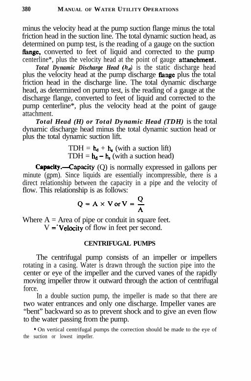
380 MANUAL OF WATER UTILITY OPERATIONS
minus the velocity head at the pump suction flange minus the totalfriction head in the suction line. The total dynamic suction head, asdetermined on pump test, is the reading of a gauge on the suctionflange, converted to feet of liquid and corrected to the pumpcenterline*, plus the velocity head at the point of gauge attanchment.
Total Dynamic Discharge Head (hd) is the static discharge headplus the velocity head at the pump discharge flange plus the totalfriction head in the discharge line. The total dynamic dischargehead, as determined on pump test, is the reading of a gauge at thedischarge flange, converted to feet of liquid and corrected to thepump centerline*, plus the velocity head at the point of gaugeattachment.
Total Head (H) or Total Dynamic Head (TDH) is the totaldynamic discharge head minus the total dynamic suction head orplus the total dynamic suction lift.
TDH = h,, + h, (with a suction lift)TDH = hd - h, (with a suction head)
Capacity.-Capacity (Q) is normally expressed in gallons perminute (gpm). Since liquids are essentially incompressible, there is adirect relationship between the capacity in a pipe and the velocity offlow. This relationship is as follows:
Q=AxVorV=z
Where A = Area of pipe or conduit in square feet.V =-Velocity of flow in feet per second.
CENTRIFUGAL PUMPS
The centrifugal pump consists of an impeller or impellersrotating in a casing. Water is drawn through the suction pipe into thecenter or eye of the impeller and the curved vanes of the rapidlymoving impeller throw it outward through the action of centrifugalforce.
In a double suction pump, the impeller is made so that there aretwo water entrances and only one discharge. Impeller vanes are“bent” backward so as to prevent shock and to give an even flowto the water passing from the pump.
* On vertical centrifugal pumps the correction should be made to the eye ofthe suction or lowest impeller.

P UMPS AND P UMP M EASUREMENT 3 8 1
In centrifugal pumps the water is given a high velocity and a cor-respondingly high velocity head. A large part of the velocity head isconverted into pressure head in the casing and the water will leaveunder this pressure to enter the discharge pipe. The velocity of thewater will depend upon the impeller velocity. Hence, since theamount of water pumped depends upon the velocity through thepump, the amount of water pumped will increase in the same ratio asimpeller speed. The head generated by the pump depends upon thevelocity head of the water and this depends upon the square of thevelocity. Hence the head varies as the square of the velocity. By atheoretical analysis, it is possible to show that the power requiredvaries as the cube of the impeller velocity, provided that theimpeller diameter remains the same. This is shown in the use of“amnity laws,” discussed later in this chapter.
Centrifugal Pump Types.-Although there are a number of dif-ferent types of pumps, the modem water system today uses only thecentrifugal type pump.
Centrifugal pumps are categorized into several different types,based on type of impeller used and number of impellers.
There are three basic types of impellers:
1. Radial flow. In this type of impeller water discharges at a 90”angle from the flow into the impeller suction eye. Radial flow im-pellers can be enclosed, open, or semi-open. It may have a single ordouble suction entrance.
2. Axial flow. In this type of impeller water discharges in thesame direction as the flow into the impeller suction eye.
3. Francis (combination of radial and axial flow). Water dis-charges at a 45” angle from the flow into the suction eye, usually withan enclosed impeller.
Further classification can involve the number and type of im-pellers and mechanical construction.
1. Turbine pumps. A multiple staged pump uses enclosed orsemi-open impellers of radial flow type. These can be installed in avertical or horizontal position. A submersible pump is a turbinepump with special motors capable of operating under water.
2. Propeller or mixed flow pumps are usually one or two-stagepumps installed vertically and employing axial or modified axial-flowimpellers. These are considered high-capacity, low-head pumps.
3. Axially split case pumps. These are commonly referred to as

3 8 2 MANUAL OF WATER UTILITY OPERATIONS
horizontal split case. They can be single or multi-staged. They use aradial flow impeller of the single or double suction design.
4. Close coupled. These pumps always use end suction im-pellers, and are usually single stage. The impeller is always attacheddirectly to the motor shaft.
Centrifugal pumps are often classified as to the type of work theyperform: booster, high service, raw water, back wash and sludge.They may employ any impeller type or mechanical construction bestsuited for the intended use.
Advantages of Centrifugal Pumps.--(l) They are simple, re-quiring no valves within the pump, (2) no internal lubrication, (3)no vacuum or air chambers on either suction or discharge, (4) arelow in first cost, requii ; very little room for their capacity and theyare practically noiseless. The disadvantages are: (1) the effect of headupon efficiency and output, and (2) the necessity for careful primingbefore the pump can be started.
If a valve on the discharge side of a centrifugal pump is closedwhile the pump is operating, the impeller will rotate without pumpingany water; however, it will build up a head, usually greater than anyhead if pumping water. This is known as the “shut-off head.” Underall conditions of pumping, no matter under what head, some wateris circulating’in the pump with the impellers, and this is known as“slip.” The less slip in a pump, the greater its efficiency, althoughthere are a number of other factors which determine the pumpefficiency.
It is quite possible to check an old pump for wear by closingthe discharge valve, reading the pressure at the discharge, deductingthe suction pressure and comparing it with the original characteris-tics of the pump. If the shut-off head is still about the same as it waswhen purchased, there has been little pump wear.
Specific Speed and Pump Type.--Specilic speed (N,) is a non-dimensional design index used to classify pump impellers as to theirtype and proportions. It is defmed as the speed in revolutions perminute at which a geometrically similar impeller would operate if itwere of such a size as to deliver one gallon per minute against onefoot head. The understanding of this definition is of design engineer-ing significance only, however, and specific speed should be thoughtof only as an index used to predict certain pump characteristics. Thefollowing formula is used to determine specific speed:

PUMPS AND PUMP MEASUREMENT 383
N*Ns= -
HS”
Where N = Pump speed in rpmQ = Capacity in gpm at the best efficiency pointH = Total head per stage at the best efficiency point
For double suction impellers, the total flow shouldbe divided by two in calculating the specific speed
The specific speed determines the general shape or class of theimpeller as depicted in Fig. 14-3. As the specific speed increases,the ratio of the impeller outlet diameter, D2, to the inlet or eyediameter, Dx, decreases. This ratio becomes 1.0 for a true axialflow impeller.
Radial flow impellers develop head principally through centri-fugal force. Pumps of higher specific speeds develop head partlyby centrifugal force and partly by axial force. A higher specificspeed indicates a pump design with head generation more by axialforces and less by centrifugal forces. An axial flow or propellerpump with a specific speed of 10,000 or greater generates its headexclusively through axial forces.
Radial impellers are generally low-flow, high-head designswhereas axial flow impellers are high-flow, low-head designs.
Net Positive Suction Head (NPSI-I).-This is a term associatedwith more complicated pumping problems such as handling liquidsand fluids at or near their boiling points. It should not be confusedwith “suction head”, because suction head refers to pressure aboveatmospheric while NPSH is concerned with vapor pressure on theabsolute scale.
In an existing system, the NPSH available can be determinedby a gauge reading on the pump suction. The following formulaapplies:
NPSHA= Pg- V,a Gr + hv
Where Gr = Gauge reading at the pump suction expressed in feet(plus if above atmospheric, minus if below atmos-pheric) corrected to the pump centerline.
h, = Velocity head in the suction pipe at the gauge connec-tion, expressed in feet.
Pa = Barometric pressureVP = Vapor pressure

3 8 4 MANUAL OF WATER UTILITY OPERATIONS
FIG. 14-3. - Profile of Pump Impeller Designs Ranging Left to Right from Low-Specific-Speed Radial Flow to High-Specific-Speed Axial Flow Placed so that EachDesign Fits the Specific-Speed Scale. (Courtesy Hydraulic Institute)
Cavitation is a term used to describe the phenomenon whichoccurs in a pump when there is insufficient NPSH available.The pressure of the liquid is reduced to a value equal to or belowits vapor pressure and smaIl vapor bubbles or pockets begin toform. As these vapor bubbles move along the impeller vanes to ahigher pressure area, they rapidly collapse.
The only way to prevent the undesirable effects of cavitation isto insure that the NPSH available in the system is greater thanthe NPSH required (NPSH,) by the pump.
Complete information on NPSH and its application in pumpproblems can be obtained from the Standards of the HydraulicInstitute, 2130 Keith Bldg., Cleveland, Ohio 44115.
Power and EBBciency.- Power is the time-rate of doing work.The work performed by a pump is a function of the total head andthe weight of the liquid pumped in a given time period. The pumpcapacity in gpm and the liquid specific gravity are normally usedin the formulas rather than the actual weight of the liquid pumped.
Pump input or brake horsepower (bhp) is the actual horsepowerdelivered to the pump shaft. Pump output or hydraulic horsepower(whp) is the liquid horsepower delivered by the pump. These twoterms are defined by the following formulas.
whp = Q x TDH x Sp. Gr.
3960(1)
bhp Q x TDH x Sp. Gr.=3960 x PumpEMiciency
(2)

P UMPS AND P UMP M EASUREMENT 385
The constant 3%0 is obtained by dividing the number or foot poundsfor one horsepower (33,000) by the weight of one gallon of water(8.33 pounds). When we are pumping water,\ the specific gravity(Sp. Gr.) is 1.0.
The brake horsepower or input to a pump is greater than thehydraulic horsepower or output due to the mechanical and hydrauliclosses incurred in the pump. Therefore the pump efficiency is theratio of these two values.
whpPumpEff,P,= - =
Q x TDH x Sp. Gr.(3)
bb 3%0 x bhp
Having figured the bhp, it becomes necessary to consider the powerinput to the motor:
Motor power input, mpi =bb
Motor Eff. (M,)
The usual power input to a motor is measured in watts or kilowatts,and since one hp is equal to 0.746 kw (which can be converted to hp bymultiplying by 1.34), the power input to the motor is:
0.746 x mpi = the unit in kilowatts. (5)
Cost of Pumping.-A frequently used formula for determiningcost of pumping is:
kwh per 1,000 gallons =kw Input to Motor x 1,000
gpm. x 60(6)
If formulas (l), (2), (4) and (5) are substituted in the above, we have:
kwh/l,OOO gals =gpm x TDH (ft) x 0.746 X 1,000
3,960 x P, x M,x gpm x 60( 7 )
Simplification of the above gives:
kwh/l,OOO gals =TDH (ft) x 0.00314
P, x Me
The kwh multiplied by the electric power rate in cents will givethe cost in cents per 1,000 gallons of water pumped under the condi-tions used in obtaining the bph.

3 8 6 MANUAL OF W ATER UTILITY O PERATIONS
Wire to water efficiency is equal to the product of the motorefficiency (M,) and the pump efficiency (P,).
Determining Power Input to a Motor.-Ordinarily the hands of anelectric watt-hour meter rotate so slowly that a reading cannot beobtained for a short interval of time, so that if a motor is beingchecked for a 15 or 20 minute period, some other way of measuringthe power input must be used. On every watt-hour meter there isa revolving aluminum disc, (sometimes two or more) which rotatesat a speed proportional to the current passing through the meter.There is a number painted in black on this disc which is called thedisc constant. One rotation equals the number of watts marked on thedisc. By timing the revolutions with a stop watch the amount ofpower can be computed. For example, suppose the disc constantis 9,. and the disc made 10 revolutions in 15 seconds. Then thenumber of watts used can be calculated from the following:
3,600 x Number of Disc Revolutions x Disc Constant
Number of Seconds
Power = 3,600 x 10 x 9/15 = 21,600 watt hours or 21.6kilowatt hours.
If there is some doubt as to the disc constant, the local electriccompany should be consulted. All other sources of power consump-tion should be cut off, and the watt meter should record only thepower being used by the motor being tested.
The power input to a motor can also be determined by thefollowing formula:
Watt hours = V x A x PF x PM x 3,600where V = Voltage
A = AmperagePF = Power FactorPM = Phase Multiplier = s
3,600 = seconds in 1 hour
If single phase current is used, the multiplier is 1, if two phasethe multiplier is fior 1.41, and if the usual three phase current, themultiplier is iTor 1.73.
Testing Pumps.-Periodically the pump operator should checkhis pumping unit efficiency and keep a record of it.
By means of gauges on the suction and discharge piping the totaldynamic head can be measured. The water pumped can be measured

PUMPS AND PUMP MEASUREMENT 387
either by a meter or by displacement in a tank. From these figuresthe water horsepower can be computed.
The electric power input to motor can be measured and con-verted to horsepower. From the horsepower input and the waterhorsepower, the “wire to water efficiency” can be calculated asfollows:
Water Horsepower
Horsepower Inputx 100 = Percent efficiency
This method can be applied in two ways: (1) the time method, wherethe total gallons of water pumped in a certain interval of time iscompared to the kilowatts or horsepower used during that time, and(2) the instantaneous method, where the rate ofpumping is comparedto the rate of power input.
In the instantaneous method the electric power input is readfrom the demand meter. The calculations by this method follow:
E =gpm x TDH x 0.746
3,960 x kw
where
E = Overall efficiency of pump and motorgpm = Rate of flow in gallons per minute
TDH = Total dynamic headkw = Kilowatt demand or input to motor.
Pump Characteristic Curves.-The performance of a cen-trifugal pump can be shown graphically on a characteristic curve.A typical characteristic curve shows the total dynamic head,brake horsepower, efficiency, and net positive suction head allplotted over the capacity range of the pump.
Figures 14-4, 5 and 6 are non-dimensional curves which in-dicate the general shape of the characteristic curves for thevarious types of pumps. They show the head, brake horsepower,and efficiency plotted as a per cent of their values at thedesign or best efficiency point of the pump.
Figure 14-4 shows that the head curve for a radial flow pumpis relatively flat and that the head decreases gradually as theflow increases. Note that the brake horsepower increasesgradually over the flow range with the maximum normally at thepoint of maximum flow.

388 MANUAL OF WATER UTILITY OPERATIONS
g OA .o f0 2 0 4 0 80 80 100 120 1 4 0
PER CENT OF DESIGN FLOW
FIG. 14-4. - Radial Flow Pump. (Courtesy Goulds Pumps,I
Mixed flow centrifugal pumps and axial flow or propellerpumps have considerably different characteristics as shown inFigs. 14-5 and 6. The head curve for a mixed flow pump issteeper than for a radial flow pump. The shut-off head is usually150 to 200 per cent of the design head. The brake horsepowerremains fairly constant over the flow range. For a typical axialflow pump, the head and brake horsepower both increasedrastically near shut-off as shown in Fig. 14-6.
The distinction between the above three classes is notabsolute, and there are many pumps with characteristics fallingsomewhere between the three. For instance, the Francis vaneimpeller would have a characteristic between the radial and mixedflow classes. Most turbine pumps are also in this same rangedepending upon their specific speeds.
160
1 4 0
120
1w
80
60
4 0
2 0
0
0 4 0 s o So 1 0 0 120 140
PER CENT OF DESIGN FLOW
FIG. 14-5. - Mixed Flow Pump. (Courtesy Goulds Pumps)

PU M P S AND PUMP M EASUREMENT 3 8 9
4 0 s o s o 1 0 0
PER CENT OF DESIGN FLOW
FIG. 14-6. - Axial Flow Pump. (Courtesy Goulds Pumps)
Figure 14-7 shows a typical pump curve as furnished by amanufacturer. It is a composite curve which tells at a glancewhat the pump will do at a given speed with various impellerdiameters from maximum to minimum. Constant horsepower,efficiency, and NPSHR lines are superimposed over the varioushead curves. It is made up from individual test curves at variousdiameters.
A&&y Laws.-The affinity laws express the mathematicalrelationship between the several variables involved in pumpperformance. They apply to all types of centrifugal and axialflow pumps. They are as follows:
1. With impeller diameter, D, held constant:
A. e-c?Ql Where Q = Capacity, gpm
Qz Nz H = Total Head, Feet
s bhp = BrakeHorsepowerN = Pump Speed, rpm

390 MANUAL OF WATER UTILITY OPERATIONS
QALLONS ?tR MlNUTt
FIG. 14-7. - Composite Performance Curves. (Courtesy Goulds Pumps)
C.
2. With speed, N, held constant:
A. -A?!.QlQ2 D2
HIB. -=
H2
C.
When the performance (QI, HI, bhpl) is known at some particularspeed (NI) or diameter (DI), the formulas can be used to estimatethe performance (QP, He, bhpz) at some other speed (N2) ordiameter (Dz). The efficiency remains nearly constant for speedchanges and for small changes in impeller diameter.

PU M P S AND PUMP M EASUREMENT 391
Example. To illustrate the use of these laws, refer to Fig.14-7. It shows the performance of a’ particular pump at 1750 rpmwith various impeller diameters. These performance data have beendetermined by actual tests by the manufacturer. Now assume thatyou have a 13” maximum diameter impeller, but you want to beltdrive the pump at 2000 rpm.
The affinity laws listed under 1 above will be used to deter-mine the new performance, with Nr = 1750 rpm and Ne = 2000rpm. The first step is to read the capacity, head, and horsepowerat several points on the 13” dia. curve in Fig. 14-7. For ex-ample, one point may be near the best efficiency point wherethe capacity is 300 gpm, the head is 160 ft, and the bhp isapproximately 20 hp.
300 1750-=-Q2 2 0 0 0
Q2 = 343 gpm
160-= HP = 209ftH 2
2 0-=bhpz
bhpz = 30hp
This will then be the best efficiency point on the new 2000t-pm curve. By performing the same calculations for several otherpoints on the 1750 t-pm curve, a new curve can be drawn whichwill approximate the pump’s performance at 2000 rpm, Fig. 14-8.
Trial and error would be required to solve this problem inreverse. In other words, assume you want to determine the speedrequired to make a rating of 343 gpm at a head of 209 ft. Youwould begin by selecting a trial speed and applying the affinitylaws to convert the desired rating to the corresponding ratingat 1750 rpm. When you arrive at the correct speed, 2000 rpm inthis case, the corresponding 1750-t-pm rating will fall on the 13”diameter curve.
System Curves.-For a specified impeller diameter and speed,a centrifugal pump has a fixed and predictable performance curve.The point where the pump operates on its curve is dependentupon the characteristics of the system in which the pump isoperating, commonly called the “System Head Curve”. By

392 MANUAL OF WATER UTILITY OPERATIONS
FIF. 14-8. - Centrifugal Pumps. (Courtesy Goulds Pumps)
plotting the system head curve and pump curve together, we cantell:
1. Where the pump will operate on its curve.2. What changes will occur if the system head curve or the
pump performance curve changes.
Static System Head. Consider the system shown in Fig. 14-9.Since the lines are oversized and relatively short, the frictionhead is small compared to the static head. For this example,the system head will be considered as entirely static, with thefriction neglected.
Assume the fluid being handled has 1.0 Sp. Gr. NPSHA is13’. The flow requirement is 100 gpm. Since the system head ismade up entirely of elevation and pressure differences, it doesnot vary with flow.
The normal system head is 250’ TDH (19’ elevation dif-ference plus 231’ pressure difference). Since the discharge vesselpressure may vary +3 psi, the system head will vary between243’ and 257’.
Consider the application of a pump sized for 100 gpm at250’ TDH, with a relatively tIat performance curve as shown inFig. 14- 10. Note that the pump will shut off at 254’ TDH. Atthe maximum discharge tank pressure, the pump will stop deliver-ing fluid, as the system head is greater than the pump TDH.

P UMPS AND P UMP M EASUREMENT 393
NORMAL SYSTEM HEAD = 231 + 19 zz 250
FIG. 14-9. - Static System Head (Courtesy Goulds Pumps)
A second consideration associated with static system head ismotor overload on pump runout. Again, consider Fig. 14-10 atthe minimum system head of 243’. The pump under discussionwill deliver 130 gpm against 243’ head. Horsepower requirementswill increase from 8.9 bhp at 100 gpm to 12.0 bhp at 130 gpm.A lO-hp motor could be overloaded on this service.
NPSH problems may also arise when large increases in flowoccur. At the rating of 100 gpm at 250’ TDH the NPSHR of thepump is only 10’ while the system NPSHA is 13’. At the lower

394 MANUAL OF WATER UTILITY OPERATIONS
FI G. 14-10. - Capacity - GPM. (Courtesy Goulds Pumps)
system head of 243’ the pump requires 13.5’ NPSH and cavitationwill probably occur.
A better selection would be a pump with a characteristic asshown in Fig. 14-l 1 _ The steeper characteristic will limit the flowto between 90 gpm at 257’ TDH and 110 gpm at 243’ TDH. Thesmall increase in capacity at low head condition will mean nomotor overload. Since the maximum flow is 110 gpm, the maxi-mum NPSHa will be 12’ and the pump will not cavitate.
Dynamic System He&.-In frictional systems where re-sistance to flow increases with flow, the system head char-aracteristic becomes curved. The magnitude of the system headat each flow is the summation of the system static head plus thetotal friction losses at that particular flow rate. A typical ex-ample of this type of system is shown in Fig. 14- 12.
Unlike the static system, the friction system is always self-correcting to some degree. Consider the above system with aflow requirement of 6000 gpm at 150’ TDH. Also assume that thedischarge tank level may drop 10’. The new system head curvewill be parallel to the original one, but 10’ lower as shown inFig. 14-13. Flow under this reduced head will be 6600 gpm at 144’rather than the normal 6000 gpm at 150’. This increased flowrate will tend to raise the discharge tank level back to normal.

P UMPS AND P UMP M EASUREMENT
FI G . 14-11. - Capacity - GPM. (Courtesy Goulds Pumps)
The frictional resistance of pipes and fittings will increase asthey wear, resulting in greater curvature of the system headcurve. A slight drop in the pump head curve may also result fromincreasing pump wear and recirculation. These changes willhave less effect on the flow in a dynamic system (steep curve)than in a static system (flat curve).
Parallel Operation.- It is sometimes desirable to use two ormore pumps in parallel rather than a single larger pump. Thisis particularly advantageous when the system flow requirementsvary greatly. One pump can be shut down when the flow re-quirement drops, allowing the remaining pump or pumps tooperate closer to their peak efficiency. It also provides an op-portunity for repairs or maintenance work on one unit withoutshutting down the entire system.
Special care must be taken in selecting pumps for paralleloperation. Consideration must be given to single pump operationin the system as well as parallel operation. Consider the systemshown in Fig. 14-14. The NPSH available is plotted along withthe system head. Since entrance and line losses increase withincreases in flow, the NPSHA decreases with flow increases.
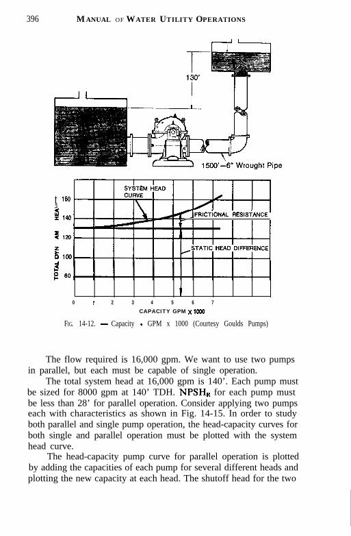
396 MANUAL OF WATER UTILITY OPERATIONS
7FRicilowL RESISTANCE. .
t 160adI 140
09 12Q
f0 loo<
t0 1 2 3 4 5 6 7
CAPACITY GPM x 1606
FIG. 14-12. - Capacity - GPM x 1000 (Courtesy Goulds Pumps)
The flow required is 16,000 gpm. We want to use two pumpsin parallel, but each must be capable of single operation.
The total system head at 16,000 gpm is 140’. Each pump mustbe sized for 8000 gpm at 140’ TDH. NPSHR for each pump mustbe less than 28’ for parallel operation. Consider applying two pumpseach with characteristics as shown in Fig. 14-15. In order to studyboth parallel and single pump operation, the head-capacity curves forboth single and parallel operation must be plotted with the systemhead curve.
The head-capacity pump curve for parallel operation is plottedby adding the capacities of each pump for several different heads andplotting the new capacity at each head. The shutoff head for the two

0 2 3 4 5 5 7 scAPAclTv QPY x lom
FIG. 14-13. - Capacity - GPM x 1000 (Courtesy Goulds Pumps)
pumps in parallel is the same as for single operation. The NPSHcurve is plotted in the same manner as shown in Fig. 14- 15. Forexample, the NPSHR for one pump at 8000 gpm is 14’. Therefore, inparallel operation 16,000 gpm can be pumped with 14’ NPSHR byeach pump.
The curves show that each pump will deliver 8000 gpm at 140’TDH when operating in parallel. Brake horsepower for each unit willbe 340-hp. NPSHR is 14’. NPSHA is 28’.
With only one pump operating, the flow will be 11,000 gpm at108’ TDH. Bhp will be 355-hp. NPSHR is 26’ and NPSHA is 30’.A 400-hp motor would be required.
This example shows that if a 3%hp motor had been selectedbased on parallel operation only, the motor would have been over-loaded in single pump operation. The single pump operation is alsoc:ritical in terms of NPSH. For example, if the system NPSHA hadb :en in the neighborhood of 20’, parallel pump operation would haveb :en fine, but single pump operation would result in cavitation.
The Suction Piping.-The allowable suction lift between thepump and the source of supply depends upon several factors. Thebarometric pressure varies somewhat from time to time but it is mostdependent upon altitude. The higher the elevation above sea level,the lower the barometric pressure and the shorter distance water
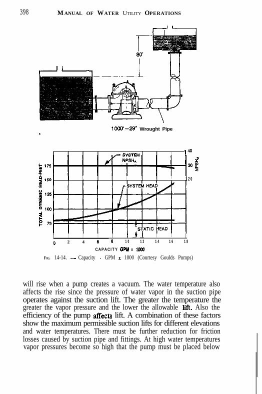
398 MANUAL OF WATER UTILITY OPERATIONS
I- I II
1000’~29” Wrought Pipe
I I I I - EVE-I-C.. I I 140
I I I I I I I I 1 2 0
I I I I I I I I6 1 0 1 2 1 4 1 6 1 80 2 4 6
CAPACITY GPM x loo0
FIG. 14-14. - Capacity - GPM x 1000 (Courtesy Goulds Pumps)
will rise when a pump creates a vacuum. The water temperature alsoaffects the rise since the pressure of water vapor in the suction pipeoperates against the suction lift. The greater the temperature thegreater the vapor pressure and the lower the allowable lift. Also theefficiency of the pump affects lift. A combination of these factorsshow the maximum permissible suction lifts for different elevationsand water temperatures. There must be further reduction for frictionlosses caused by suction pipe and fittings. At high water temperaturesvapor pressures become so high that the pump must be placed below
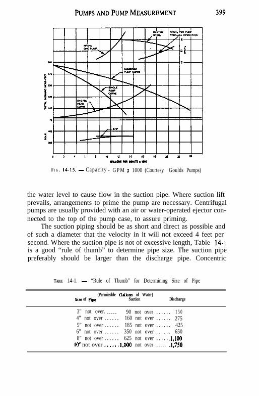
PUMPSANDPUMPMEASUREMENT
a I d 6 * to II 1. I‘ 1‘ 2n P 24O)*LO)*m-xtm
FI G . 14-15. - Capaci ty - G P M x 1000 (Courtesy Goulds Pumps)
the water level to cause flow in the suction pipe. Where suction liftprevails, arrangements to prime the pump are necessary. Centrifugalpumps are usually provided with an air or water-operated ejector con-nected to the top of the pump case, to assure priming.
The suction piping should be as short and direct as possible andof such a diameter that the velocity in it will not exceed 4 feet persecond. Where the suction pipe is not of excessive length, Table 14- 1is a good “rule of thumb” to determine pipe size. The suction pipepreferably should be larger than the discharge pipe. Concentric
TABLE 14-1. - “Rule of Thumb” for Determining Size of Pipe
(Permissible Gdbnr of Water)Si+c of Pipe Suction Discharge
3” not over. . . . . . 90 not over . . . . . . 1 5 04” not over . . . . . . 160 not over . . . . . . 2755” not over . . . . . . 185 not over . . . . . . 4256” not over . . . . . . 350 not over . . . . . . 6508” not over . . . . . . 625 not over . . . . . .l,lOO
lo” not over ...... 1,000 not over . . . . . .1,750

400 M ANUAL OF W ATER UTILIT Y OPERATIONS
reducers are undesirable when reducing suction pipe diameter topump suction diameter. An eccentric reducer should be used whenconnecting directly from the pump suction piping, or if to a pipefitting, the fitting opening should be of the same diameter as thesuction pipe. The short “throw” of the eccentric reducer fittingshould be on the top.
If it is necessary to use an elbow or bend horizontally in thesuction piping, it should be located at a distance from the pumpsuction connection, so the flow of water will tend to be equal andnot along one side of the suction connection to the pump.
A suction pipe should never be level. In order to avoid airpockets it should slope upwards toward the pump from the sourceof supply. Good practice requires that it be tested under pressureregularly for leaks.
Noise in a centrifugal pump is an indication of impact. Air, orother gases present in the water, or derived from air leaks in thesuction piping or in the pump packing, may cause the noise. If notso caused, it is an indication of poor pump application, which causesseparation of air and gases from the water and causes wear or pittingof the impeller and pump casing. This separation within the pumpcasing is known as cavitation.
Rotation.-Indicating the direction of rotation of a pump isconfusing unless it is noted which end is being observed. Differentmanufacturers use different ends as the place to observe rotation;therefore., always indicate which end is being observed whendesignating rotation. No matter what the observation point, if theobserver will state whether he is looking at the outboard end or thedriving end, and from that point the suction is on the right or leftof him, he will give the rotation of the pump. A plan drawing ofthe pump layout is always of assistance to the manufacturer.
Selecting Pumps.-Prior to the purchase of any centrifugalpump, study the pump curves or obtain the services of someonewho is competent to study and advise the best pump for the job. Itis unwise to select a pump on price alone or on efficiency (operatingcosts) alone. The pump must not only meet the head and capacitycalled for, but should fit into the system and be able to operatewith it.
Whether a pump is the right one to purchase can always bedetermined by answering this question: “How will this pump meetthe system requirements and conditions, not only for today but a
P UMPS AND P UMP M EASUREMENT 401
few years from now?” It is impossible to figure all conditions thatwill govern pump operation many years hence; but will the pumplose its usefulness with any increase of water requirements? If itwill, it is not the pump at any price. It is good practice to purchasea pump with an impeller less in diameter than the maximum impellersize for that pump. If a pump is purchased with the maximum sizeimpeller to start with, its volume and head cannot be increased.It is good practice to have plenty of extra motor power to increasevolume or head or both if it becomes necessary at a later date. Thepump will not use any more power than required by the conditionsunder which it operates, regardless of the motor size. It is noteconomical, however, to use a motor considerably in excess of re-quirements. Motor efficiencies vary little between three-quarters andfull load. At one-half load and when overloaded, efficiency drops.
Pumps are usually designed to operate at speeds equivalent tofull load motor speeds. For 60 cycle operation, these are. approxi-mately 3,500 t-pm, 1,750 x-pm, 1,160 rpm, 870 t-pm and 695 rpm.These will vary some depending on the manufacturer and on thesize of the motor. The efficiency of the squirrel cage type motorsis from i/i to 1% percent greater at 1,750 rpm and 1,160 rpm speedsthan at higher or lower speeds. This is a general rule and is notexact for all classes of motors.
It has already been noted that in order to obtain high heads, theperipheral speed of the impeller must be high. There are three waysof obtaining this result: (1) by using a larger diameter impeller,(2) by increasing the impeller speed, and (3) by adding stages. Ofthe three ways, the second is usually the least expensive, althoughthere are cases where the second and third methods must be com-bined to obtain extra high heads. Slower speeds are more desirable,but if high heads are necessary and the volume to be pumped isrelatively low, high speed pumps or multi-stage pumps must be used.
Generally, if pumps are aligned properly, the high speed oneswill require just as little maintenance as the slow speed pumps andthe replacement parts are cheaper. In the majority of cases, thehigh speed pump will prove more-efficient than the low speed pumpfor the same job.
The double-suction axially-split pump is recognized as being thebest suited for water plants. These pumps were developed to takecare of certain conditions encountered in municipal service. Theupper half of the pump case and the entire rotating element can be
402 MANUAL OF WATER UTILITY OPERATIONS
removed without disturbing the piping. Prior to this development,end-suction pumps with single-suction impellers were used, withthe motor and pump mounted on a base plate and with flexiblecoupling being used between the pump and motor. This was theforerunner of the present day close coupled pump, with its impellermounted on an extended motor shaft, with little or no base andwith no coupling, and the pump housing and motor housing com-bined into an integral unit.
For small installations and for auxiliary units the close coupledpumps are quite desirable. They are easily installed, take little spaceand, as there is no coupling, alignment is unnecessary. Althoughthey are less expensive in the smaller sixes than double-suctionpumps, caution should be used in their selection. Some of this typepump have been put on the market as a competitive product, withno quality built into them. The better constructed close-coupledtype pumps compare favorably with the double-suction type.
There are some features about these pumps which make themless desirable for full municipal service. Inspection of the impelleror any of the internal parts requires that suction and discharge pipingbe disturbed. The packing gland is usually in a location which isdifficult to reach, and therefore packing is more difficult. The pipingenters and leaves the pump at right angles and in different planes,instead of a straight line. Standard stock motors cannot be usedas the shaft on this type pump is extended to hold the impeller shaft.
INSTALLATION, OPERATION AND MAINTENANCE
Where two or more pumps are to be operated, discharging theminto the same header or distribution mains, special care should betaken that the pumps are designed for the same maximum headconditions. A pump, especially of the centrifugal type, if designed forlower head conditions, will “cut-back” or decrease the quantity dis-charged per minute, and will “cut-out” or cease to discharge ifthe shut-off head of the other pump or pumps is sufficiently higher.
Proper location,of a pump will facilitate good operation. A light,dry, clean room, where the temperature can be regulated, withsufficient head room and ample space between pumps and nearbywalls should be of prime consideration.
Foundations should be rigid, about 1 inch lower than pump baseelevation, with foundation bolts of proper size with threads of suf-
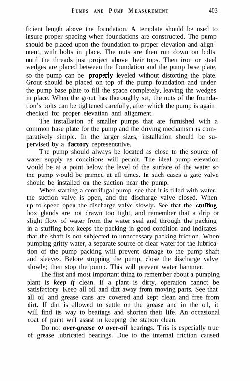
P UMPS AND P UMP M EASUREMENT 403
ficient length above the foundation. A template should be used toinsure proper spacing when foundations are constructed. The pumpshould be placed upon the foundation to proper elevation and align-ment, with bolts in place. The nuts are then run down on boltsuntil the threads just project above their tops. Then iron or steelwedges are placed between the foundation and the pump base plate,so the pump can be prop’erly leveled without distorting the plate.Grout should be placed on top of the pump foundation and underthe pump base plate to fill the space completely, leaving the wedgesin place. When the grout has thoroughly set, the nuts of the founda-tion’s bolts can be tightened carefully, after which the pump is againchecked for proper elevation and alignment.
The installation of smaller pumps that are furnished with acommon base plate for the pump and the driving mechanism is com-paratively simple. In the larger sizes, installation should be su-pervised by a factory representative.
The pump should always be located as close to the source ofwater supply as conditions will permit. The ideal pump elevationwould be at a point below the level of the surface of the water sothe pump would be primed at all times. In such cases a gate valveshould be installed on the suction near the pump.
When starting a centrifugal pump, see that it is tilled with water,the suction valve is open, and the discharge valve closed. Whenup to speed open the discharge valve slowly. See that the stuffingbox glands are not drawn too tight, and remember that a drip orslight flow of water from the water seal and through the packingin a stuffing box keeps the packing in good condition and indicatesthat the shaft is not subjected to unnecessary packing friction. Whenpumping gritty water, a separate source of clear water for the lubrica-tion of the pump packing will prevent damage to the pump shaftand sleeves. Before stopping the pump, close the discharge valveslowly; then stop the pump. This will prevent water hammer.
The first and most important thing to remember about a pumpingplant is keep if clean. If a plant is dirty, operation cannot besatisfactory. Keep all oil and dirt away from moving parts. See thatall oil and grease cans are covered and kept clean and free fromdirt. If dirt is allowed to settle on the grease and in the oil, itwill find its way to beatings and shorten their life. An occasionalcoat of paint will assist in keeping the station clean.
Do not over-grease or over-oil bearings. This is especially trueof grease lubricated bearings. Due to the internal friction caused

404 MANUAL OF WATER U TILITY OPERATIONS
by the churning of grease, a bearing will run hotter if the greasepocket is packed tight. It is good practice to remove the oil or greasecompletely from the reservoir every 6 to 12 months, depending onconstancy of operation, flush with solvent and refill. There is usuallyan indicating mark on oil lubricated bearings to show the properoil level. If the grease lubricated bearing retainer is one-half full ofgrease, it has enough. Do not let employees give these bearings a“shot” of grease every day or so. It will cause trouble. One suchapplication will last several months.
If there is a noise or vibration, check the difficulty. Determinethe trouble and stop it. If allowed to continue, it may develop intoa major repair bill. A centrifugal pump should not vibrate. In fact,any vibration probably means misalignment. Misalignment will causewear and expense.
If the pump and motor continue to get out of alignment, dis-connect the pump from its suction and discharge piping. There shouldbe no strain from either the suction or the discharge. The pipe flangesand pump flanges should match completely and fit jam up face-to-face. A centrifugal pump is made of cast iron and will not standa strain. Any distortion, even if it does not break the pump, willnot only cause internal wear, but external wear and lost efficiency.
If the suction line is a long one, be sure that there is some sortof flexible coupling in it to prevent its having any effect on the pump.This is true of the discharge line whether it is a short or long line.Be sure that the packing glands are loose. A tight packing gland willscore the shaft sleeve. When once scored, the glands cannot beproperly adjusted unless they are renewed.
When packing a pump, Crst obtain packing recommended orfurnished by the manufacturer for that pump. If it is not already cut,cut it to exact size, straight across, never on the bias. Be sure thelantern gland is in its proper place with rings of packing on each sideof it. Stagger the joints of the packing when placing in the glandopening. Tamp each ring of the packing in place gently but tirmly.Pull the packing into place with the glands when all rings are in-stalled. Pull it up rather tight, then back it off until it is loose. Startthe pump and after running a few minutes or until there is con-siderable leakage of water about the gland, pull up the glands “thumb-tight.” Always allow a small amount of water to leak through thepacking gland. This acts as a lubricant and protects the shaft sleeve.
Any pump requiring under 75 hp motor should turn freely with

PU M P S AND PUMP M EASUREMENT 405
hand operation. Larger pumps and motors will require more powerto turn. If the pump will not turn freely, look for a tight gland orbad bearing. Be sure there is no air in the pump when starting. Airwill at times leak into a pump through the glands when the pumpis not running if the suction lift is high. Such a condition would occurif the foot valve leaked. If surges are caused at starting or stoppingthe pump, close the discharge valve before starting or stopping. Onstarting, open the valve slowly when pump comes up to speed. Onstopping, close valve completely before stopping the motor.
Valves are made which will accomplish this operation auto-matically, and will eliminate line surges caused by starting andstopping.
Be sure suction valves are wide open. Have discharge valveswide open unless it is necessary to build up an artificial head. Athrottled discharge valve may act as an ejector and will draw airinto the line through the valve packing.
Parallel Operation.-Frequently the question is asked, “Whatwill this pump do when operating in parallel?” There are manyvariables which will determine the answer, but the most importantare the pump characteristics and the line characteristics. Withoutthese two, no proper answer can be given. If the pump characteristiccurves are not available, they can be obtained from the manufactureron request. Send in the figure number, shop number or serial numberof the pump or pumps and the manufacturer will gladly send thecurves to you. The line characteristics are not so easily obtained,especially for a distribution system. Where there is a long supplyline, this can be determined from friction tables and plotted.
Every parallel operation is a problem in itself, and no rules canbe followed to state how much additional water can be pumped withparallel operation. Even pumps of similar characteristics sometimescannot be used to obtain additional water in parallel operation.
When pumps are operated in parallel, the volumes are added.When pumps are operated in series the heads are added.
Pump characteristics and line characteristics combine to deter-mine the possibility of operating pumps in parallel. It is easier toparallel pumps when the friction loss is comparatively low. Anadditional pump with proper characteristics for the desired in-creased volume may be more economical than attempting to parallelexisting pumps. Series operation on small lines will increase theamount of water that can be obtained.

406 MANUAL OF WATER UTILITY OPERATIONS
POWER SOURCES
(1) Steam.-Not used extensively any more.(2) Oil Engines.-These include the diesels and semi-diesels.
They are of constant and comparatively low speed. They are highin first cost but are reliable and economical. They are frequently usedin small installations where electricity is not available, expensive orunreliable. They require considerable operating skill.
(3) GasoIiw Engines.-These are generally used as standby oremergency units. They are low in first cost, but very high in operatingcost. They generally operate at 600 to 1,800 revolutions per minutewith speed control at the carburetor. They can be direct-connectedto centrifugal pumps. A common installation is to have an electricmotor on one end of the shaft and the gasoline engine at the otherend where it can easily be coupled on should the current or motorfail.
(4) Motors.-Electric motors can be secured in a wide range ofspeeds, and are well adapted for direct connection to centrifugalpumps. Capacity of a motor depends upon how much heat it canstand. There are two types of motors, the direct current and thealternating current motor.
Direct current motors are seldom used at the present time dueto the fact that direct current is generally unavailable unless it isgenerated at the pump station, and practically all motors manu-factured now are of the alternating current type.
Alternating current motors of three types can be secured, eachoffering distinct types of service. They are: a, the squirrel-cageinduction motor; b, the wound-rotor (slip-ring) induction motor;and c, the synchronous motor.
a. The squirrel-cage induction motor is the simplest of allmotors. It gets its name from the winding on the rotor which con-sists of heavy copper bars welded to the end rings, forming a devicesimilar to the exercise wheel in pet squirrel cages. The squirrel-cage motors do not have moving rings, brushes, or wire connectionsto the rotating part; the speed is constant, as fixed by the frequencyand number of poles. They are without adjustment, and are easilycontrolled manually or by remote control equipment. The startingtorque is low, and when demanded, the current draft on the line isheavy. Their efficiency is high but the power factor is low. Theyare not well adapted to starting heavy loads, requiring larger trans-formers and power lines, and higher cost for power used.

PUMPSANDPUMPMEASUREMENT 407
6. The wound-rotor or “slip-ring” motor has similar windingson the rotating and stationary parts, with the ends of the windings con-nected to the “slip-rings” on the shafts. The starting torque can bevaried from 30 to 375 percent of full-load torque. These motors areof variable speed, and cost from one and one-half to two times thecost of squirrel-cage motors, but the savings in power when thehead varies will more than pay the interest and depreciation on theadditional investment. The power factor is less than unity, requiringlarger transformers and power lines, and generally higher cost forpower used.
c. The synchronous motor gets its name from the fact that itruns in synchronism (i.e., at the same frequency) as the generatorsupplying the power. It is a constant speed motor, the speed de-pending on the number of poles in the motor Geld. Its advantagesare that it operates at the same speed at all loads, its efficiency isusually higher than an induction motor and if used in combinationwith inductive loads, it will improve the electrical efficiency of thesystem. It has the disadvantages of requiring an exciting generatorto energize the field; its speed cannot be changed; and it requiresmore skilled and intelligent operation.
VARIABLE SPEED DRIVES
In the past several years a variety of drivers which can vary thespeed of the centrifugal pump have been used. The two most com-mon, which are described here, are the magnetic air cooled type andthe fluid drive type.
The affinity laws state that the volume of a centrifugal pumpwill vary in direct proportion to the speed and the head pump willvary in proportion to the square of the speed. Therefore, the drivewhich will automatically and continuously vary the speed of acentrifugal pump will offer the operator of a water system manyadvantages. There are many manufacturers of variable speed drives.They can be purchased in every conceivable engineering principle.These principles could be mechanical variable speed devices,variable foot pitch pulleys, and planetary gears. These mechanicalpower transmissions have an efficiency of about 90 percent and aregenerally driven by a conventional squirrel cage motor. Electricmotors are also widely used as variable speed machines. Directcurrent motors are excellent drivers, while many makes of altemat-
4 0 8 MANUAL OF WATER UTILITY OPERATIONS
ing current motors use various methods of variable speed control.In general, alternating current variable speed control follows two orthree broad categories. These are wound rotor, reactor type andvariable frequency. One of the more popular forms of electricalvariable speed drive is the magnetic or eddy-current coupling.
The magnetic coupling is an electrical variable speed devicethat works on the eddy current principle. A standard electric motoris connected to an outer, rotating, sliploss dissipating ring usuallydriven at a constant speed. An inner rotating direct current excitedmagnetic member is directly connected to the load to be driven. Theonly mechanical connection between the inner and outer memberconsists of anti-friction bearings which for all practical purposestransmit no torque. Direct current is applied to the inner magneticmember through slip rings. Direct current saturation is used to varythe output speed. The more direct current excitation applied to themagnetic member the higher the output rpm, because more magneticlines of flux grab at the constant speed outer member, thereby reduc-ing slip between the two units.
The magnetic variable speed drives are available in almost anydesired horsepower, speed range and duty cycle. They are availablein various types of enclosures making them suitable for both indoorand outdoor applications. They are available in both horizontal andvertical types of construction.
The second type of variable speed drive is the fluid coupling.The fluid coupling has been used quite extensively in variable speedpump service. The first fluid drives were made as early as 1905 inGermany. Horsepowers are such as to produce speeds ranging from3,500 to 14,000 rpm.
Basically a fluid coupling as used today consists of two rotatingelements with opposing segmented hemispheric shells contained in acasing. The casing is called a torus. The driving member is calledan impeller, and the driven member called the runner. The speed ofthe runner is a function of the quantity of oil rotating in the torus.By varying the quantity of oil in the torus, the slip of the runnercan be controlled and thus vary the output speed. When the rotatingtorus is full of oil, then the maximum speed is obtained in therunner, which is approximately 97 percent of the full load speed ofthe motor.
The level of the oil in the torus is varied by means of a scooptube which removes excess oil from the coupling. The raising and
PUMPS AND PUMP MEASUREMENT 409
lowering of the scoop tube will vary the speed of the runner indirect proportion.
The output speed of variable speed drives can be controlledthrough several different types of actuating devices. One of thecommon types is a liquid level control which through the purgingof air wilI maintain a constant liquid level in a tank. This constantmonitoring of the liquid level within a tank will vary the speed ofthe pump and thereby increase and decrease the pump capacity indirect proportion to the change of speed. A second common actuatingdevice is the pressure control. Through a system of diaphragms, thecontrol will monitor the pressure within a system, and vary the speedautomatically of the drive and pump and thereby maintain a constantpressure within the system.
MOTOR STARTERS
The following types of starters are most generally used withpumping equipment:
1. Magnetic, Full Voltage (across the line).(a) Push Button Operated. (b) Selector Switch Operated.
2. Magnetic, Reduced Voltage.(a) Push Button Operated. (b) Selector Switch Operated.
3. Combination, Magnetic Full Voltage with(a) Fused Switch. (b) Non-Fused Switch. (c) Circuit
B r e a k e r S w i t c h .4. Increment Start.The full voltage magnetic type of starter is most generally used.
It has both overload and under-voltage protection. There is lessmaintenance required and fewer moving parts in these starters than inany other type giving comparable results. Keep the contacts of thesestarters clean. Never use anything to block these starters in theclosed position. If a starter continues to kick out, determine thecause and correct it. Be absolutely certain that the switch is suppliedwith the proper heater strips for the motor being used. This typestarter can be operated by a push button with momentary contacts,which may be mounted in the starter cover or in a separate receptacle,or it may be .operated through a hand-off automatic selector switchwhen used with a float or pressure control or some other pilot device.
Where power feeders are long or where the power companywill not allow full voltage magnetic starters (usually with large

410 MANUAL OF WATER UTILITY OPERATIONS
motors), the reduced voltage starter is used. The manual type isused when it is not necessary to operate the pumps from pilot devicesand when the initial cost is given consideration.
The combination starters combine all of the features of themagnetic full voltage starters with a means of disconnecting theparticular circuit from the feeder panel. The Underwriters Code re-quires that a disconnect switch be placed within sight of every motor.In order to simplify the wiring and house in one cabinet, the dis-connect device and the starter, the combination starter was de-veloped. This eliminated the necessity of wiring between the dis-connect and the starter in the field, and assured the proper sizeswitch and starter combination being used for the motor size.
Generally speaking, four types of enclosures are used: (1) Themost commonly used is Type 1, or general purpose metal enclosures;(2) Type 4, watertight metal enclosure; (3) Type 5, dust tight en-closure; and (4) Type 7, known as Class 1, Group D, is Under-writers approved for hazardous locations where gas or other ex-plosive fumes might be encountered.
V&age.-Voltage is usually established by the engineer or bythe availability of current. The 440-volt current is most economicalif available. A 220-volt circuit requires heavier insulation. On largerinstallations it is both feasible and economical to use 2,300-voltcircuits as this will save, in some cases, the cost of transformersand transformer losses.
DEEP WELL TURBINE PUMPS
Deep well turbine pumps are not true turbine pumps, but areactually smaIl series centrifugal pumps and have the characteristicsof centrifugal pumps, particularly the relations between speed,output, head and power. Due to the requirement that they be oflimited size to fit’inside the well casing, the amount of head whicheach stage can develop is limited and it is necessary to combineseveral stages in order to develop the higher heads required for mostwell pumping jobs.
For example, if one stage will deliver 300 gpm at 25foot head,to deliver 300 gpm at 200 foot head would require 200 + 25, or 8stages.
Since these pumps are actually series centrifugal pumps, thequestion of selection of a proper pump follows very closely the dis-

PUMPS AND PUMP MEASUREMENT 4 1 1
cussion under centrifugal pumps. The head capacity curves,efficiency curves and horsepower curves resemble those of cen-trifugal pumps and need no separate discussion.
The efficiency, as usually stated, is of the pump bowls or stagesthemselves and some additional horsepower is required because ofshaft losses and pipe friction through the discharge column whichmay be an appreciable amount in deep settings. In obtaining effi-ciency curves, it is well to be certain whether the shaft losses andcolumn friction losses are included.
The essential parts of a deep well turbine pump are an engineor motor driver, a well head supporting the driver and containingthe discharge connection, and also transmitting the load of the pumpto the foundation, the column pipe, the shaft and bearings and thestages.
This type is particularly suited for electric motor operation byuse of a vertical motor, either hollow shaft or solid shaft. Thesepumps are also adapted to engine operation through a quarter-turnflat belt or through a right-angle gear drive. If standby power isrequired, a combination drive can be obtained whereby an electricmotor and an engine both can be installed on the same shaft.
Since all of the load of the pump, column and shaft is carriedto the foundation through the pump head, it is necessary to providesome sort of thrust beating to carry the load. In the solid-shaftmotor, a thrust bearing is built in the pump head. In the hollow-shaft motor the pump shaft extends through the hollow motor shaftand the thrust bearing is built in the top of the motor. In the right-angle gear drive the thrust is usually carried in the geared drive.An adjusting nut is provided at the top of the pump shaft to insurethe positioning of the impellers in their place in the pump casing.
Underground discharges, formerly used, are no longer approvedfor municipal water supply due to the impossibility of properly sealingthe space between the well casing and the pump column.
The pump column is usually made of threaded and coupled pipeor llanged couplings. The column is usually in lO-foot lengths,carefully cut to exact length and the ends machined square. Thecouplings for the coiumn are of special design, each having a spiderinside which forms a support for the shaft bearing retainer. Theshaft is thus supported at lo-ft intervals.
There are two types of bearings used, the oil lubricated and thewater lubricated. The oil lubricated type requires an outer oil pipearound the shaft, and oil is fed into this oil pipe at the top of the

412 MANUAL OF WATER UTILITY OPERATIONS
well. In the water lubricated type the shaft is open to the water,and the bearings are usually of rubber inserted in the bearing retainersand the water serves as a lubricant.
In the water lubricated type, water should be admitted backdown the shaft from the top before starting the pump to preventdamage to the bearings above the normal water level.
There is still difference of opinion concerning the best type oflubrication and most manufacturers make both oil and water-lubricated pumps. The water-lubricated pump is simpler, has no oilcolumn, weighs less, is easier to install and remove, and will notcontaminate water in the well with oil. The oil-lubricated pump hasmore positive lubrication and does not require pre-lubrication. Itis somewhat easier to adapt to automatic operation as a solenoidvalve can be used on the oiler to start feeding oil when the pumpstarts. In the water-lubricated pump a more complicated automaticcontrol is necessary to assure that proper pre-lubrication is carriedout. Sometimes a small hole is drilled through the check valve or asmall line is allowed to run constantly to assure proper pre-lubrica-tion. A great deal of damage to the shaft bearings may result fromfailure to pre-lubricate the pump.
Since the pump itself is actually a series centrifugal pump,there are several types of impellers used with claims of better effi-ciency and less trouble from sand for each one.
In selecting a pump, it should be remembered that the headconditions may vary considerably for any one pump, both whenstarting and stopping, and seasonally due to variations of water levelsin the wells. An impeller of the non-overloading type should beselected if much variation is expected and motor sizes should beselected to avoid overload of the motor at any point in the rangeof pump capacity.
In areas where water levels are receding or can be expected torecede, it is usually economical to select a shaft size and motor sizeto permit future lowering of the pump in the well without over-loading either the shaft or ‘the motor. It is desirable to install an airline in the well to test water levels and drawdowns when operating.
It is no longer customary to bolt deep-well turbine pumps downto the foundation as the weight of the pump will hold it in place.No well pump should be installed in a well which is not straightand vertical. No effort should ever be made to force a pump in acrooked well as it will not operate satisfactorily. The pump shouldhang free in the well before grouting. A Dresser or other flexible

P UMPS AND P UMP M EASUREMENT 4 1 3
coupling should be used to connect the pump discharge pipe toavoid transmitting any pipe stresses to the pump.
The foundation for a deep well pump should be high enoughabove ground to be above any possible surface water level. The pumpbase should be grouted to seal the base watertight and all openingsthrough the pump base should be plugged except for a breather pipe.This pipe should have a return ell with the opening looking downand screened to exclude insects. Any gland leakage water should bepiped away from the pump base.
A type of deep-well turbine is now available in which the motoris submerged in the water in the well. The motor is Hled with oilof high electric insulation properties and a relay is provided to cutoff the pump if the water level reaches too close to the motor,thus preventing its operation until the oil level has been restored toits proper level through the oil f3ler line.
A cable is carried from the surface to the motor. Since thiscable is outside the pump column, it may be subject to damage byabrasion if the well casing is only a little larger than the overalldiameter of the pump and cable, and care must be exercised tominimize the rubbing of the cable against the.well casing.
Since this type of pump does not have a long shaft, it eliminatesbearing troubles and power losses from the shafting. It is especiallyadapted to wells which are crooked since the whole motor pump isone unit of comparatively short length and is not affected by mostwell irregularities.
If this type of pump is used in an area of receding water levels,it is wise to purchase the original cable long enough to permit lower-ing the pump without splicing the cable.
The well head is merely a !‘lat plate with a pipe elbow attachedand the electrical cable is brought into a simple control box. Thistype of pump can be made very inconspicuous on the surface. Thetendency is to place the well head too low which sometimes allowssurface water to rise up to or over the outlet when only the wellseal will prevent contamination. The seal where the cable passesthrough the welI casing or the top plate is a possible source of leakageunless care is taken to make a watertight seal at this point.
Deep-well turbine pumps are not used exclusively as wellpumps, as they have been adapted for use as booster pumps on pipelines, low lift pumps pumping from rivers or lakes and high liftPUMPS pumping from reservoirs into the distributing system.
Keeping Records.-Keeping proper records at a pumping station

414 MANUAL OF WATER UTILITY OPERATIONS
cannot be too strongly stressed. The total amount of water pumpeddaily, the amount pumped by each pump if possible, the suction anddischarge pressures, the number of hours by each pump, and thedaily power consumption are the very minimum. In addition, otherrecords such as rainfall, temperature, voltage, amperage, powerfactor, fuel consumption in the case of gas, gasoline or diesel engines,repair records, cost, and the like should be mentioned.
In case of a well supply, a log of the well should be obtainedwhen the well is constructed. A record of static levels, drawdownand quantity pumped from each well should be kept. Other recordsmay be desired as indicated by local conditions.
ACKNOWLEDGMENTS
Much of the material contained in this chapter was condensedwith permission from thestandards of the Hydraulic Institute, 2130Keith Bldg., Cleveland, Ohio and from a brochure prepared byGoulds Pumps Inc., Seneca Falls, New York, particularly thesections on “Fundamental .Terms” and “Centrifugal Pumps;” sub-sections “Pump Characteristic Curves”, “Affinity Laws”, and“System Curves”. The figures were reproduced from these sourceswith credits indicated.

CHAPTER 15
MOTORS AND MOTOR CONTROLS
CHARLES R. McCREARY, P.E.
Charles R. McCreary and Associates
The purpose of this chapter on electric motors and controls is to pres-ent a general discussion of the principal types of motors and motor con-trols used in the water utility field. Attention will be focused on generalpurpose induction motors and conventional controls. \
ELECTRICAL
Basic Characteristics. - Electric motors are selected to fit thedrive requirements, system voltage characteristics, and to operate satis-factorily in the ambient environment. Starting and running torques mustmatch load requirements. Voltage, phase, and frequency must match thepower supply. Winding insulation type can be selected to endure mois-ture, chemical attack, frequent starting, and high ambient temperature,depending upon the application.
Standard line current frequency for the United States is 60 hertz.This characteristic used to be referred to as 60 cycles. The hertz designa-tion more accurately states cycles per second; the required time for oneelectrical wave to repeat itself is one cycle. For 60 hertz power it is about16 milliseconds. A three-phase motor responds to the line current witha rotating magnetic field that is in synchronism with the applied frequen-cy. A single-phase motor responds with a pulsating magnetic field andits rotor will not rotate unless some auxiliary means are provided to shiftthe flux in the iron circuit to provide a starting torque.
An electric motor, whether three-phase or single-phase has a rotorspeed that is a function of the number of poles with which the stator iswound. The rotor speed never catches up with the rotating magnetic fieldin an induction motor field but it always rotates at a speed slightly lessthan the synchronous speed. This difference in speed is called the “slip”.Most motors run with a 2% to 3% slip. For example, an induction motorthat would run at 1800 rpm if there were no slip, would run at 1760 rpmwith 2% slip.
Induction motor slip characteristics are designed into the motor by
415
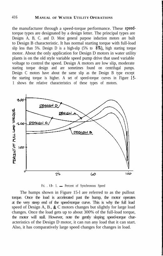
416 MANUAL OF WATER UTILITY OPERATIONS
the manufacturer through a speed-torque performance. These speed-torque types are designated by a design letter. The principal types areDesigns A, B, C. and D. Most general purpose induction motors are builtto Design B characteristic. It has normal starting torque with full-loadslip less than 5%. Design D is a high-slip (5% to 8%), high starting torquemotor. About the only application for Design D motors in water utilityplants is on the old style variable speed pump drive that used variablevoltage to control the speed. Design A motors are low slip, moderatestarting torque design and are sometimes found on centrifugal pumps.Design C motors have about the same slip as the Design B type exceptthe starting torque is higher. A set of speed-torque curves in Figure 151 shows the relative characteristics of these types of motors.
0
28 60 I&
FIG . 15 1. - Percent of Synchronous Speed
The humps shown in Figure 15-l are referred to as the pullouttorque. Once the load is accelerated past the hump, the motor operatesat the very steep end of the speed-torque curve. This is why the full loadspeed of Design A, B., & C motors changes but slightly for large loadchanges. Once the load gets up to about 300% of the full-load torque,the motor will stall. However, note the gently sloping speed-torque char-acteristics of the Design D motor, it can run any load that it can start.Also, it has comparatively large speed changes for changes in load.

MOTORSANDMOTOR CONTROLS 417
Voltage ratings of motors are found on the motor’s nameplate. Itwill be noted that the voltage is less than the applied line voltage. Forexample, a motor with 460 volts on the nameplate is designed to operateon a 480V nominal system voltage. This appears to be a discrepancy butit is actually a considered design development. The motor is nameplatedat the lower voltage because there is a line voltage drop from the supplysource to the motor. The supply source, which is usually a utility trans-former is nameplated at a higher voltage. These nominal voltages followstandards. Table 15-1 lists common source and load voltages.
There has been a general increase in nominal voltages in the lastthirty years. In the 1950’s, a typical three-phase motor nameplate wouldread 208-220/44OV. This means that the motor had a dual winding foroperation at 220V or 440V; also, it would operate with a little highertemperature rise at 208 V. In the 1960’s the motor manufacturers, actingthrough National Electrical Manufacturers Association (NEMA),changed the voltages to adjust them to the higher system voltages. The208V dual rating was dropped and a separate 200V rated motor designwas manufactured. Now, we have 230V instead of 22OV, 460V insteadof 440v.
Motors are wound to accommodate small increase and decreasesin the supply line voltage. The standard range is plus-or-minus 10% fromthe motor’s nameplate voltage. This range allows in-plant voltage varia-tions. When the voltage increases above the motor’s nameplate voltage,the current goes down, conversely, when the supply voltage decreases,the current goes up. This inverse relationship exists for small changesbecause the motor attempts to deliver the same shaft horsepower outputand since the horsepower is proportional to the product of VxI when Vgoes up, I goes down and vice-versa. Beyond the upper and lower limitsof the 10% range, the currents rise dramatically. These phenomena areshown in Figures 2a and 2b.
The above voltage curve is approximately for older “U” frame mo-tors and the new energy-efficient motors. For the modern “T” frame lineof motors, the curve has a narrower trough and rises more rapidly at theextremes of the 10% tolerance range.
A motor’s tolerance to voltage variations is affected mainly by theamount and quality of the magnet steel and magnetic air gap construc-tion, when operating under nameplate conditions. The more magnet steelused and the higher its quality (high grade silicon steel instead of plaincarbon steel) the more tolerant the motor becomes to voltage changesand suffers less degradation of its life.
A motor nameplate will have the service factor stamped upon it for

418 MANUAL OF WATER UTILITY OPERATIONS
~~FECT&,,V’~~~~&T~d~
FIG . 15-2a. - Effect of Voltage Variations on “U” Frame Motors
motors that comply with NEMA standards. International standards donot recognize service factors. The NEMA standard defines service factorof an ac motor as a multiplier, and where applied to the motor’s ratedhorsepower, indicates a permissible horsepower loading which may becarried under the conditions specified for the service factor. This servicefactor is usually 1.15 (or 15%) for open motors and was originally devel-oped to coincide with temperature limits of motor insulation. Motors rat-ed from 1 l/2 hp through 200 hp have a 15% service factor and motorsabove 200 hp are not rated in accordance with NEMA standards. l/2hp through 1 have a 1.25 service factor. Totally enclosed motors normallyhave a 1.0 service factor; however, they can be purchased with a 15%service factor.
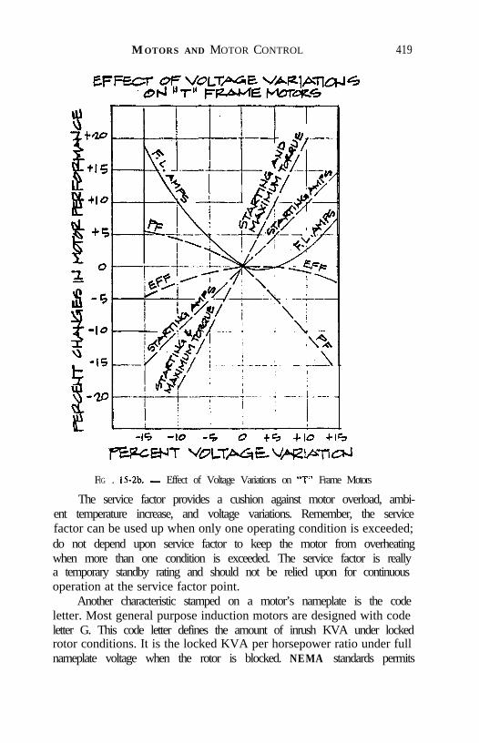
MOTORS AND MOTOR CONTROL 419
FIG . 152b. - Effect of Voltage Variations on “T” Frame Motors
The service factor provides a cushion against motor overload, ambi-ent temperature increase, and voltage variations. Remember, the servicefactor can be used up when only one operating condition is exceeded;do not depend upon service factor to keep the motor from overheatingwhen more than one condition is exceeded. The service factor is reallya temporary standby rating and should not be relied upon for continuousoperation at the service factor point.
Another characteristic stamped on a motor’s nameplate is the codeletter. Most general purpose induction motors are designed with codeletter G. This code letter defines the amount of inrush KVA under lockedrotor conditions. It is the locked KVA per horsepower ratio under fullnameplate voltage when the rotor is blocked. NEMA standards permits

420 MANUAL OF WATER UTIL,ITY OPERATIONS
an allowable range of values for a particular code letter. For example,code letter G range is 5.60 to 6.29 locked KVA per hp. Code letter Fis 5.59 to 6.29. Most plant motors will be found to be code letter F, G,or H.
The code letter relates to the inrush current when a motor startsunder across-the-line, full-voltage conditions. Although the rotor is notblocked, the rotor is at a standstill when started and its inertia causesit to approach the factor blocked rotor test. Since KVA is a product ofcurrent and voltage, the code letter average value reflects the ratio ofinrush current over rear current. For a code letter G motor, inrush cur-rent is about 6 times the full load current.
Sometimes, the power company will require that a large motor bestarted at reduced voltage so as to reduce the current impact on theirdistribution system. If their requirement is not too stringent, a code letterF motor in place of code letter G, for example, might be able to satisfythe utility’s requirements. This is an economical alternative since the ad-ditional price for code letter F is only about 10% of the motor’s price.On a code letter F motor with across-the-line starter, the cost is one-halfthe cost of a standard motor with reduced voltage starter for a 100 hpsize.
Motor nameplates do not usually give the motor efficiency. The newlines of energy efficient motors will have the NEMA nominal efficiencystamped thereon. Motor efficiency has become more important to plantoperators as the cost of electrical energy has risen. Motors consume about64% of all power produced in the United States. Specifically, motors rat-ed 1 to 125 hp consume 20% of all electric power generated; therefore,an increase in efficiency of ,l% would be significant, even for one plantsystem.
For standard “T” frame general purpose motors, efficiencies rangefrom about 75% on the small integral horsepower sizes to about 90% onthe 200 hp size. For the new “energy efficient” motors, efficiencies areseveral points higher in each rating. Refer to Figure 15-3 for a compari-s o n .
Manufacturers increase the motor efficiency by reducing the powerlosses in two main ways: 1) Improve the magnetic circuit and 2) Lowerthe resistance of the windings. To improve the magnetic circuit, moreiron can be added to the rotor and stator stack, thinner laminations ofcore steel can be made, and a better grade of core steel can be used suchas silicon steel in place of carbon steel. Also, the magnetic circuit canbe improved by reducing the air gap so as to reduce stray losses. In sofar as the windings are concerned, losses can be reduced by reducing their

MOTORS AND MOTOR CONTROL 421
IaJ --
WFlClEtJT45--
I II IIII II II II
44 5 IO w 305 IO w 3 0 Q 15Q 15 ICLG %=2ICLG %=2oUrPuT liM!VWoUrPuT liM!VW
FIG , 15-3. - Emergency EfficiencyF IG , 15-3. - Emergency Efficiency
resistance: copper instead of aluminum and larger wire sizes. About 65%of the motor’s total losses occur in the iron and in the stator windings.
One last nameplate topic, a basic motor characteristic is the insula-tion class. This topic is explored under “Temperature and InsulationConsiderations”.
Types of Motors. - When direct current (dc) motors were devel-oped commercially, one would have thought that they had gone aboutas far as they could go with the development of series, shunt, and com-pound wound dc motors, however they are not used in water and wastewater plants to any extent. Sometimes they are found on flocculatorsand mixers and the shunt wound dc motor is applied for speed control.When George Westinghouse with his alternating current system won outover Edison’s dc system, a floodgate of alternating current motor designwas opened.
Alternating current (ac) motors can be divided into two main types:synchronous and induction motors.
Synchronous motors have two variations, excited and unexcited, andare not ordinarily found in the small and medium motor sizes (below500 hp). It is typically a 1000 hp or greater size motor and it is usually

422 MANUAL OF WATER UTILITY OPERATIONS
designed to run at very low speeds (less than 600 rpm). The rotor of asynchronous motor turns in synchronism with the revolving magneticfield induced in the air gap by the stator windings. An excited synchro-nous motor has a direct current field on the rotor and the north and southpoles of the rotor are usually exposed or salient pole type. The excitationfor an excited synchronous motor can come from a rectified revolvingfield on the rotor, called self-excited, or it can come through slip ringconnections from an external dc source, called separately excited.
The synchronous motor has rotor bars embedded in its pole facesto cause it to act like an induction motor during start so that the rotorcan develop enough torque to accelerate its load. These short-circuitedbars have the appearance of a large induction motor rotor with brazedbar construction. They are called Amortisseur windings.
Excited synchronous motors are found on large, low-speed pumps,fans, blowers, and compressors in the water utility plant. They are usual-ly directly shaft-connected to their load. Controls are much more compli-cated for a synchronous motor than for an induction motor.
Unexcited synchronous motors do not use rotor windings but havemodified rotors to cause the flux to form about poles or magnets are em-bedded in the rotors to form the poles. A recent offering by one nationalmotor manufacturer’s catalog lists the magnet type unexcited synchro-nous motor in small (l-5 hp) sizes. These are used with centrifugal pumpsand fans either to run at synchronous speeds or to be used with a variablefrequency controller for precise speed control.
The excited synchronous motor can, in addition to providing shaftpower, provide power factor correction to plant electrical distributionsystems. It can do this by the amount of dc field current applied to therotor. If the field current applied is set above a certain minimum value,the power factor of the machine becomes leading. This field current set-ting is usually fixed by the manufacturer so that the motor runs underload at 0.8 power factor, leading and is so stamped on the motor’s name-plate. Plant induction motors typically operate with 0.8 power factor lag-ging and if enough KVAR at 0.8 leading can be supplied by the synchro-nous motor, the plant power Bystem will operate at unity power factor,to the delight of the power company.
The induction motor has many variations, both in single phase typesand in three phase types. These include wound rotor, single speed andsquirrel cage multiple speed. They are the mainstay of a water or wastewater plant power system. The emphasis will be on the general purposeinduction motor, especially the three-phase, 60 hertz induction motor.For generality some of the many different types of induction motors will

MOTORSANDMOTOR CONTROL 423
be explored.First the Wound-rotor motor is made for both single-phase and
three-phase motor but the single-phase types such as the repulsion-in-duction type and the repulsion type have all but disappeared from themarketplace, and the remaining wound-rotor single-phase motor is theseries type that is used mainly on hand tools. The three-phase wound-rotor motor is rarely found in water utility plant work except for someold variable-speed pump drives and sometimes in a modern solid-statespeed control application. The three-phase wound-rotor motor uses sliprings on the rotor to bring out the rotor windings. These are wired toa starter with a complement of starting resistance, or, the heavy-dutyrun type resistors that are used for speed control. Usually, the wound-rotor motor was used for providing smooth starts with low inrush currentfor large fans, pumps, and compressors. In the typical start-only resistortype wound-rotor motor control, the motor’s slip rings are short-circui-ting at rated speed. Thereupon, the motor continues to operate like asquirrel cage induction motor. Wound-rotor motors can be wound formultispeed operation but these are rare. Speed control through the useof solid-state inverters in the secondary slip-ring circuit can providesmooth variable speed along with power feedback into the primary sup-ply lines for energy conservation.
Wound rotor motors are expensive and there is a maintenance prob-lem in the care of the slip rings and associated brushes. Such motors arenot usually made in totally enclosed construction nor are they usuallymade except in horizontal, foot-mounted models.
The squirrel-cage induction motor is the principal motor found inall types of drives in a water utilities plant. It is used in small fans andpumps as well as large blowers, pumps, and compressors. Three-phasetypes are used primarily and single-phase types are used in fractionalhorsepower on small pumps and fans.
Single-phase squirrel-cage induction motors are mostly the capaci-tor type or split-phase design. A single-phase motor must have an auxilia-ry starting device. This device shifts the stator flux so that there is atorque developed. Otherwise, the rotor would stand still and hum as notorque would be developed. There are three principal types of single-phase, squirrel-cage motors; these are shaded-pole, split-phase, and thecapacitor motor. The capacitor motor is usually found as a capacitor-start type but there are variations such as the capacitor-start, capacitor-run and the permanent split-capacitor (PSC) motor. Each of the threetypes has a place according to the starting torques required. The capaci-tor-start has the highest starting torque compared to the shaded-pole and

424 MANUAL OF WATER UTILITY OPERATIONS
the split-phase types.The three-phase squirrel-cage induction motor is a marvel of con-
struction simplicity. It converts electrical energy to mechanical energywith a high degree of efficiency and with only one moving part. For some-thing built so simply, it is amazing that it can have complicated theoriesto explain its operation and can have volumes written about its.design,performance, and application.
The stator windings of the three-phase squirrel cage motor can bearranged to provide the number of poles and phases needed, and to pro-vide multi-speed operation, both in dual winding or in consequent-pole,single winding. The windings can be arranged for constant horsepower,constant torque, or variable torque to suit the type of load. Stator win-dings involve distribution and pitch factors to establish the desired rotat-ing magnetic field in the air gap.
Magnet wire for stator windings comes in two types: round and rec-tangular in cross-section. The round wire is used in the smaller sizes ofmotors, usually found in 150 hp and smaller for 600V class motors. Suchwindings are referred to as “mush-wound” or “random-wound” type.Above that horsepower, the “form-wound” windings with rectangularcross-section wire are used, and are laid as a set into an open slot in thestator. The mush-wound type is randomly laid into the stator slots, usual-ly by machine.
Squirrel-cage induction motors run at one speed when line frequen-cy is kept constant. Variable speed was once obtained at some sacrificein performance with variable voltage control mentioned earlier. Withthe advent of efficient solid-state power switching devices, a standard
TABLE 15-l.- Source and Load Voltages
Standard StandardVoltaP;eSupDlv Motor Voltages
120 115208 200240 230480 460
squirrel-cage induction motor can be driven over a wide range of speedsand with a variable frequency drive control. More accurately, it is a vari-able frequency/variable voltage controller. For an induction motor tooperate at a different frequency the voltage must be changed in such

MOTORSANDMOTORCONTROL 4 2 5
manner to keep the volts per cycle constant.Temperature and Insulation Considerations. - There are two
stampings on the motor nameplate that were not discussed under BasicCharacteristics. These are the ambient temperature and the insulationclass. So much development has occurred in the insulation products thata separate article is devoted to this topic.
The ambient temperature, NEMA Standard, is 40 degrees C (105degrees F) and this is the reference temperature for standard generalpurpose motors. A motor is usually labeled to operate continuously atrated load under correct voltage and frequency conditions, in an ambienttemperature of 40 degrees C. There are many days in Texas when theambient temperature exceeds 105 degrees F and the motors do not fail.Remember the service factor? Also, a motor can and does fail a littleat a time. The winding insulation ages more rapidly under higher temper-ature and the life of the motor is shortened.
Motor life is dependent on the integrity and durability of its insula-tion. Heat degrades insulation. Tests have shown that motor life is cutin half for each 10 degrees C above the insulation temperature capabilityand is doubled for each 10 degrees C below that capability.
The progress made in insulation is astounding. Formvar, a patentedinsulation formulation became available in the fifties and allowed highertemperature rise than permitted under the old Class A windings. Themotor manufacturers were quick to take advantage of the improvementsin insulation. A five horsepower motor is put in a frame size today thatwas used for a one horsepower motor built in the forties.
Table 15-2 lists the temperature rise for the several insulationsystems, according to NEMA standards for enclosed motors with no ser-vice factor and operated at rated load.
TABLE 15-2. - Insulation Classes and Temperature
Class A----------------------60 degrees C
Class B----------------------80 degrees C
Class F---------------------l05 degrees C
Class H---------------------126 degrees C

426 MANUAL OF WATER UTILITY OPERATIONS
The corresponding temperatures for 1.15 service factor rated mo-tors are ten degrees higher in each category.
The Class F insulation system is generally used today in most motorwindings for the general purpose induction motor. It is a durable, nonhy-groscopic winding that allows the motor to operate in a 40 degree C ambi-ent plus another 10 degrees C allowance for hot-spot inside the motor.
To take advantage of the Class F insulation system temperature riseand gain either a larger service factor or longer life for a particular motor,some operators and engineers specify that the motor be wound with ClassF wire but that the temperature rise be limited to that of a Class B orClass A insulation system. This puts the motor in a special category andhas some merit, but it has to be weighed against the costs and deliverytime.
Often, especially in the larger horsepower sizes, a standard motorcan be purchased at the next horsepower size and the same benefits canbe achieved at a cost reduction. This may not be so in the smaller horse-power sizes because of larger differences between horsepower ratings.
OPERATIONAL CONSIDERATIONS
To be succinct operational considerations are confined mainly tothe general purpose, squirrel-cage induction motor.
Under Basic Characteristics we touched on what happened whenthe voltage increased or decreased from the nominal voltage rating ofthe motor. Within the 10% limits, a voltage increase caused the motor’scurrent to decrease and a voltage decrease caused the current to increase.The changes are about proportional to the percent of change.
When the applied voltage is non-uniform or there is a differencebetween the phase voltages, a motor suffers much more than when theapplied voltage is uniformly changed. A small percentage unbalance willresult in a large amount of heat generated in the motor. The unbalancedvoltages create a negative torque that opposes the positive torque of therotor. The rotor overheats and causes stator windings to overheat. Thisunbalance is calculated as the high phase voltage minus the average ofall three phase voltages divided by the average and multiplied by 100.For example, assume a 460V motor and the supply line voltage is 480V(phase A), 470V (phase B) and 465V (phase C). The high voltage is480V and the average voltage is 472 volts. Now place these values inthe above formula and we find: 480 - 472 x 100/472 = 1.69. There isa 5 to 6 times that percentage current draw over that which would existwith balanced voltages applied. It requires only a slight unbalance of

MOTORS AND MOTOR CONTROLS 421
applied voltage to cause large unbalanced currents and large amount ofheating. If the system voltage unbalance goes above 3% try to get it cor-rected. The utility is usually at fault and is usually cooperative in correc-ting the system.
Remember that a 1.15 service factor can be expended by a smallunbalance alone, leaving nothing to accommodate overloads, and over-temperature conditions.
Besides the hidden heating effects of unbalanced voltage, anotheroperational consideration of induction motors that causes hidden deterio-ration of the windings is too many starts per hour. NEMA has standardson the number of cold starts and hot starts that a motor can safely with-stand. There is rapid heating anytime a motor starts and the more startsin a short time the higher the heating in the rotor and in the stator win-dings. More than two or three cold starts in fifteen minutes can causemotor overheating.
Akin to motor starts is the stalled rotor condition. Most motors arerated to take locked rotor condition for ten seconds. This is a severe oper-ating condition and one to which motor protective devices may not re-spond quickly enough. The rotor temperature is accelerating at 100 de-grees C per second while the stator may only rise 10 degrees C per second.The protective devices all sense in one way or another the condition ofthe stator. Fortunately, the locked rotor condition is something that doesnot happen often.
One environmental condition that happens often is the occurrenceof moisture. Heat and moisture are the two principal enemies of electricalequipment. Moisture is not as important on present day motors as onthe older models that used more hygroscopic insulations. It does degradea motor’s insulation envelope and make it more susceptible to damagefrom line impulses.
Totally enclosed motors that start and stop are prime candidatesfor moisture ingress. A totally enclosed fan-cooled (TEFC) motor whichis turned on and off, will have condensate inside it. This is why motormanufacturers put drain plugs in the bottoms of TEFC frames. A spaceheater is sometimes provided to prevent moisture build-up or condensa-tion on the windings. These are usually factory installed but there aresome belt-type space heaters that can be field installed. They need tobe turned on when the motor is stopped. Heating of motor windings byimpressing a low voltage when the motor is off is considered more effec-tive than space heaters in the motor; however, this involves starter modi-fications and is more expensive than the space heater approach.
When moisture lowers the insulation level of a motor’s windings,

428 MANUAL OF WATER UTILITY OPERATIONS
an impulse of a couple of thousand volts can damage a winding thatmight otherwise be harmlessly dissipated. Most motors are rated to with-stand 1OOOV plus their rated voltage. One protection that is inexpensiveis to install a lightning arrester on the terminals of the motor. This shouldprotect against most lightning secondary effects and switching surges.Some additional insurance is through installation of a three-phase surgecapacitor. It acts to smooth out and lower the rate of rise of the voltagespike.
The power factor (PF) is highest when the motor is fully loaded andit drops off for lesser loads. When induction motors start and also whenthey are running at no or little load, the PF can drop to the thirty percentrange. If the power company assesses a penalty for low PF, it behoovesthe plant operator to improve his system to save money. Even if thereis no penalty, a low in-plant PF can cost money from cable heating andlessening of available cable capacity because of increased currents. Usu-ally installation of a synchronous motor or capacitor banks will improvethe PF. Note in the article on motor types that a synchronous motor canbe used to drive a load and at the same time provide a leading PF. Thismay be a costly way to correct PF. The conventional, economical ap-proach is to install small PF correction capacitors at the motor terminals.Carefully follow capacitor and motor manufacturer’s recommendedmaximum capacitor KVAR sizes or you may damage your motor drivetrain if too large a capacitor is installed.
The capacitor problem is related to a recent phenomena that plantoperators observe when a standby generator switches from standby tonormal. With luck only a breaker trips, but a large motor can be lostif the transfer is made at the wrong time in terms of the phase-anglerelationship between the system voltage and the open-circuit voltage.The same phenomena exists when a capacitor and motor combinationis switched back on before the motor coasts down. Actually the motoris acting like a generator for a few milliseconds. The capacitor is capableof supplying a certain amount of excitation or magnetizing current asit discharges back into the motor. When the motor is turned back ontoo quickly, the rotor is snatched back into step with the line frequencyand the resulting mechanical impact can break the motor shaft, or itscoupling to the driven apparatus.
Be cautious of the application of large motors on frequently swit-ched circuits, standby generators without in-phase on time-delay trans-fer schemes, or with too large power factor correction capacitors. Checkwith the motor manufacturer when you have a motor rated 100 hp orover as to its “open circuit time constant”. This will usually be about
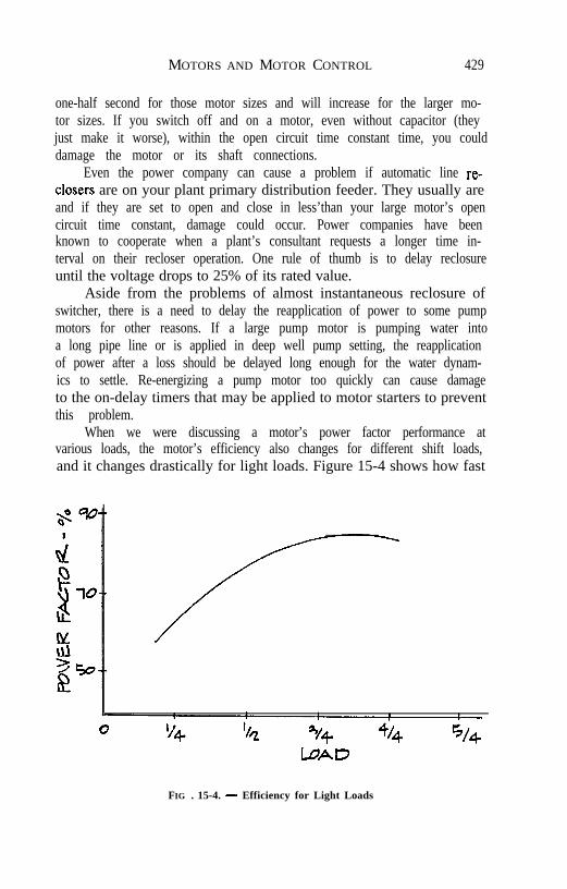
MOTORS AND MOTOR CONTROL 429
one-half second for those motor sizes and will increase for the larger mo-tor sizes. If you switch off and on a motor, even without capacitor (theyjust make it worse), within the open circuit time constant time, you coulddamage the motor or its shaft connections.
Even the power company can cause a problem if automatic line re-closers are on your plant primary distribution feeder. They usually areand if they are set to open and close in less’than your large motor’s opencircuit time constant, damage could occur. Power companies have beenknown to cooperate when a plant’s consultant requests a longer time in-terval on their recloser operation. One rule of thumb is to delay reclosureuntil the voltage drops to 25% of its rated value.
Aside from the problems of almost instantaneous reclosure ofswitcher, there is a need to delay the reapplication of power to some pumpmotors for other reasons. If a large pump motor is pumping water intoa long pipe line or is applied in deep well pump setting, the reapplicationof power after a loss should be delayed long enough for the water dynam-ics to settle. Re-energizing a pump motor too quickly can cause damageto the on-delay timers that may be applied to motor starters to preventthis problem.
When we were discussing a motor’s power factor performance atvarious loads, the motor’s efficiency also changes for different shift loads,and it changes drastically for light loads. Figure 15-4 shows how fast
FIG . 15-4. - Efficiency for Light Loads
430 MANUAL OF WATER UTILITY OPERATIONS
the efficiency drops for light loads. Even at full-load the efficiency ofa typical 100 hp induction motor will drop several points. The peak istypically at and above 3/4 load.
A motor’s efficiency is affected by heat, which can come from high-er ambient temperature than 40 degrees C, unbalanced voltages, abnor-mal balanced line voltage, too frequent starting duty, or dirt. The’latterconditions can be corrected by good housekeeping. The windings in anopen motor can accumulate a fair amount of dirt deposit over time. Also,a TEFC or TENV (totally enclosed non-ventilated) motor can accumu-late a layer of grime over the cooling fins that diminish heat transfer.
Considering motor life, energy conservation, and power factor, agood compromise would be to specify a next larger horsepower motorso as to have the motor run cooler, last longer and operate more efficient-ly. Add a small package of power factor correction capacitors at the mo-tor terminals and feel confident of a balanced plant electrical system.
Thirty-six hundred rpm, 1800 rpm, and 1200 rpm induction motorsoperate at a 85% to 90% PF at full load for sizes above 5 horsepower.The smaller the motor, the lightly loaded motor, or the slow speed motoroperate at lower PF’s.
MECHANICAL
Enclosures for motors are manufactured to comply with NEMAstandards. The principal types of enclosures are: 1) open drip-proof(ODP), 2) Totally enclosed non-ventilated (TENV), 3) Totally enclosedfan-cooled (TEFC), 4) Weather protected, Type 1 (WPI), and 5) Weath-er protected, Type II (WPII).
Most ODP type fractional horsepower and small integral framesizes are built with sheet metal stator housing and cast metal end-plates.Few “open” motors are made any more, the manufacturers in the fiftiesbegan to add shielding inside the end-plates to make them open-drip-proof. The NEMA specification for drip-proof is stated such that theenclosure construction prevents drops of liquid or solid particles fallingat angles of 15 degrees or less from the vertical from entering the motor.
The larger frame size integrals and the slower speed motors, whichrequire a larger frame size, are usually built with cast-iron frames. Also,the TENV and TEFC motors are built with cast iron frames.
Totally enclosed non-ventilated motors do not have an external fanas do the totally-enclosed fan-cooled style. However, both have internalfans that serve to move the air around the end-turns of the windings.This fan is typically a cast aluminum extension of the rotor squirrel cage.

MOTORS AND MOTOR CONTROLS 431
Explosion-proof motors are constructed with cast-metal housingsin a TEFC configuration, and may appear to the unfamiliar observeras a TEFC. There are some important differences: There are two or morethrough-bolts than the TEFC, the rabbet fits of the end bells are milledto closer tolerance and have longer lengths than the TEFC, the junctionbox is cast metal and has four or more bolts and the split openings havelonger surfaces than do the TEFC. Moreover, the manufacturer has beentested and labeled by UL to meet hazardous area environments. Explo-sion-proof is somewhat of a misnomer in that the motor’s design is suchthat it can prevent an internal explosion from igniting surrounding gases.The longer milled fits of the end-bells and the junction box cool the inter-nally ignited gas-air or dust-air mixture to a degree that it falls belowits ignition point. So, when the explosive mixture puffs out, the surround-ing environmental gas is not ignited.
There are several classifications for explosive environments. Thetwo main groups, Division 1 and Division 2 are classified for degree ofhazard. This is, some TEFC motors are suitable for Division 1 applica-tions where the hazardous environment is not likely to be present and,if so, it quickly dissipates. Division 2 applications are the most severein that the hazardous environment is a Class 1 (combustible gases andvapors), a Class 2 (combustible dust) or a Class 3 (combustible fibers).In addition to the Divisions and Classes, there are Group classificationssuch as Groups A, B, C, D for combustible gases and Groups E and Gor combustible dusts. As an example, methane has a Group D classifica-tion.
An important design criteria for the motor manufacturer is to limitthe maximum surface temperature of the motor below the ignition tem-perature of the hazardous atmosphere. For example, acetylene has anignition temperature of 305 degrees C. A motor would have a GroupA label for such application. Most explosion-proof motors are found withthe following labeling: Division 1, Class 1, Groups C & D. This labelingmakes the motor safe for lower volatility gases and most dusts.
There are two types of motor enclosures designated as weatherpro-tected, WPl and the WP2 classifications, and are used to define the typeof environmental protection for large motors with fabricated steel enclo-sures. Many larger vertical and horizontal pump motors are built in ClassWPl or WP2. The main difference between WP2 and WPl constructionis the number of baffles used to change the direction of cooling air sothat large water droplets and dust are removed from the air stream andprevented from entering the stator windings. Also, WP2 style motorhousings are constructed with corrosion-resistant hardware.

432 MANUAL OF WATER UTILITY OPERATIONS
NEMA standards cover frame sizes from the 48 through the 500series frame. These frame designations carry certain shaft and keywaysizes, shaft height, and other standard dimensions such as mounting holedimensions. This standardization enables the purchaser to buy a certaingeneral purpose horsepower and speed motor from several manufactur-ers and be assured that the mounting and shaft dimensions are the same.
All motors have bearings on which the shafts are supported. Thepurpose of a bearing is to reduce friction and wear. Bearings are usedto centrally support the rotating member (rotor) while providing a rigidsupport for the output shaft. The bearing is the connection point betweenthe rotating and stationary elements of a motor. Most conventional mo-tors use a ball bearing connection. Ball bearings are mass-produced,standardized and relatively inexpensive. Sleeve bearings are still used,particularly in the fractional horsepower fan and blower motors. Evenin large horizontal pump motors, sleeve bearings are used for their long-life and low noise characteristics.
Sleeve bearings are lubricated by oil while ball bearings can be lu-bricated by oil or grease. Sleeve bearings provide cylindrical surfaceswhich the rotor slides against through a thin film of oil. Sleeve bearingscannot take much thrust so they are used for direct connected applica-tions. Whereas the typical antifriction ball bearing can take thrust loads.
The main types of anti-friction bearings are: 1) single row, deepgroove; 2) single, maximum capacity; 3) angular contact; 4) double row;5) ball thrust; 6) roller thrust; and 7) cylindrical.
The single row, deep-groove bearing is listed as type “BC” and issometimes called a Conrad bearing. This is the most commonly usedbearing in small and medium size induction motors. The bearing raceshave no filling slot; the balls are inserted by offsetting the races. Suchbearings give good performance under light to moderate radial loads andrelatively moderate thrust loads. The single row, deep groove bearingis somewhat self-aligning.
The single row, maximum capacity ball bearing is listed as type“BL” and contains the maximum complement of balls inserted througha slot in the raceways. Since this type bearing contains more balls thanthe Conrad type, it can withstand higher radial loads, however, this typebearing will not take thrust loading or accommodate angular misalign-ment.
The angular contact bearing is designed to carry high thrust loadsin one direction and can carry also a combined radial with thrust loading.These bearings are designed with an offset wide shoulder, one on the out-er race and one on the inner race, located on opposite sides of the bearing.
MOTORSANDMOTORCONTROLS 433
The wide shoulder designates the direction of thrust. Angular contactbearings can be stacked either face-to-face or back-to-back to permitcombinations of thrust and radial loading. These bearings can carrygreater thrust loading than the Conrad or the maximum style bearings.Three disadvantages of this type bearing are: 1) if mounted with thethrust shoulder in the wrong direction, moderate thrusts will destroy thebearing; 2) they are expensive; and 3) they are not as readily availableas common Conrad bearings.
Double row self-aligning ball bearings have two rows of balls; itsconstruction compensates for angular misalignment resulting frommounting mistakes, and compensates for shaft deflection and mountingdistortions. Self-aligning bearings of this type are recommended for radi-al loads and moderate thrust loads in either direction.
Ball thrust and roller thrust bearings are designed for high thrustloads. The spherical roller thrust bearing combines a very high load-car-rying capacity in either thrust loading or combined thrust and axial load-ing. Spherical roller bearings are subject to speed limitations of 1200rpm (grease lubricated) and 1800 rpm (oil lubricated).
Cylindrical roller bearings are used where large radial-only loadsare imposed. Physically, this bearing is interchangeable with the ballbearing in any given size. The speed range on the cylindrical roller bear-ing is low. They can operate at 1800 rpm if oil lubricated and 1200 rpmif grease lubricated. If any thrust loading is imposed, some means mustbe used to absorb the thrust. For example, a cylindrical roller bearingcan be used on the shaft-end of a motor and a ball type bearing put onthe opposite shaft end, for some belt connected high radial, low-thrusttype loading.
Bearings require lubrication to minimize metal-to-metal contact.At standstill, sleeve and ball cylindrical, and spherical type bearings havea minute metal-to-metal contact and after only a few degrees of rotationthe lubrication moves between the metal surfaces.
As the shaft in a sleeve bearing starts to rotate, it climbs up the wallof the bearing. As it climbs, the shaft rolls onto a thicker film of oil andit begins to slip back. This wedge-shaped cavity causes oil to be drawninto the bearing contact area and the shaft then rides on a thin film ofoil. On larger motors oil is carried from a reservoir to the top of the shaftby a slinger ring that rides atop the shaft. Small motors use a wick anda one-piece bearing. Larger integral horsepower motors use a split bear-ing with slingers. Sleeve bearings will last the life of the motor if theoil film is maintained between the sliding surfaces.
Ball, spherical, and cylindrical bearings, and the anti-friction type

434 MANUAL OF WATER UTILITY OPERATIONS
bearing family, can be oil or grease lubricated. Actually, it is the oil thatlubricates and grease is a carrier for the oil. Because of the need for oilreservoir, grease offers a simple method of lubrication. Grease is some-what self-containing; also it is a good sealant and corrosion inhibitor.There are several standard greases available, these and their applicationare:
1. Sodium/petroleum - Operation in -20 degrees F to 200 degreesF (-20 degrees C to 93 degrees C) temperatures, good rust protection,low resistance to rotation
2. Lithium/petroleum - Operation in -40 degrees F to 200 degreesF (-40 degrees C to 93 degrees C), insoluble in water and recommendedfor high moisture environments.
3. Lithium/silicones - Operation in -40 degrees F to 350 degreesF (-40 degrees C to 177 degrees C), adequate moisture resistance butrestricted load carrying capabilities.
4. Polyurea/mineral oil - Operation in -40 degrees F to 350 degreesF (-40 degrees C to 177 degrees C), good moisture resistance, good lubri-cation qualities, and good load carrying characteristics.
The anti-friction bearing grease reservoir designs fall into three ma-jor types: 1) open bearing construction; 2) shielded bearing construction;and 3) sealed bearing construction.
Open bearing construction uses a grease cavity in the end bell thatis in proximity to the bearing. There is a removable cap on the insideof the end bell to allow access to the bearing and sometimes a removablecap is placed on the outside of the end bell housing. These caps, or guards,hold the grease in its cavity. They usually are machined to have a closefitting clearance about the shaft. Inlet grease port and outlet relief portare provided by means of threaded plugs. Sometimes, an “Alemite” or“Zerk” fitting is used on the top inlet port to aid in grease insertion bymeans of a grease gun. The advantages of this construction are coolerbearing operating temperatures and capability of regreasing.
The shielded bearing is similar to a Conrad bearing except that ashield, usually mounted on both sides of the bearing faces, is provided.This shield is a metallic disc that is machined to have a mechanical fitto the outer race and a restrictive annular fit at the inner race. This annu-lar fit provides a small lubrication path, allowing a shield bearing to berelubricated.Also, the shield retains the lubricant to the rolling elements regardlessof the degree of fill of the adjacent grease cavity. The shields primarypurpose is to prevent the entrance of large foreign particles into the ra-ceway surfaces. One other function of the shield is to provide slinger-ac-

MOTORSANDMOTORCONTROLS 435
tion relubrication to the rotating bodies of the bearing.A sealed bearing construction is similar to the shielded bearing ex-
cept that a non-metallic disc is mounted on both faces of the bearingraces. Each sealing disc is fitted tight against the outer race and remainsstationary. A sliding sealing contact is made with the inner race. Sealedball bearings are widely used and are considered to be lubricated for“lifetime”. They wear out and do so frequently, if not more so than theshielded and open types. Their life is restricted to the lubrication packedbetween the seals of the bearing. Maintenance is to replace the bearing.There are heating problems, particularly on the larger sizes; therefore,sealed bearings are not available in the larger sizes; the most importantfeature of a sealed bearing is its ability to shield the bearing surfacesfrom contaminents. This type bearing is widely standardized and isreadily available at a reasonable cost. Its use in motors has allowed themanufacturers to simplify the end bell construction and gain cost savingstherefrom.
Bearings fail and do so a little at a time if operated within theirthrust and load capacity, thermal capacity, and operated free from con-taminents and abuse. Most direct-coupled motors will operate for100,000 hours before experiencing a bearing failure. Some will fail earli-er and some will fail later. Before asking for warranty repairs, look atthe method and temperature of operation and possible abuse. Failuresof bearings usually result from one or more of these reasons.

CHAPTER 16
AUTOMATIC VALVES FORTHE WATER UTILITY
J. E. LESCOVICH
GA Industries, Inc.
The subject of valves for the control of water can be as diverse asany topic encountered in the water works field. There are many varietiesof valves available, and it would be impossible to discuss the merits ofevery valve type in one chapter; therefore, ,discussion will be limited toautomatic valves normally encountered in the water works field. Mostof the automatic valves discussed would not be used in sewage service.Also, small valves used for chemical feeding and such are not discussed,because each manufacturer’s product is better described in the specificdata sheet for that unit.
This chapter will emphasize types and functions of automatic valvesgenerally found in a water utility. One point however, that we do wantto emphasize about valves such as the Gate Valve, Plug Valve, Butterflyand the like, is that these valves were never intended for continuous throt-tling.
GENERAL COMMENTS
There are some general statements that can be made relating to con-trol valves usually found in water treatment plants and distributionsystems. Usually the working pressure is below about 100 pi, and onlya small number of valves operate at pressures up to about 250 psi, there-fore, for pressures normally encountered, the valve bodies can be madeof cast iron. Typically in the United States, cast iron flanges are rated125 or 250 ANSI (American National Standards Institute). Flanges forhigher pressure ratings are usually of steel and are more expensive.
It should be remembered that the 125 lb. ANSI flange pressure rat-ing is actually a saturated steam pressure rating. The American WaterWorks Association (AWWA) has permitted the 125 lb. ANSI flangeto be used to 250 psi water pressure. Rating a flange for 125 psi or 250psi does not automatically make the entire valve or fitting suitable forthat pressure. Each fitting or valve body has its own particular shape
436
AUTOMATIC VALVES FOR THE WATER UTILITY 437
or geometry to consider. The valve or fitting manufacturers stipulate themaximum allowable working pressure for their products.
For more information on ANSI flange pressure ratings, it is suggest-ed that a copy of the ANSI B16.1 for cast iron, and ANSI B16.5 forsteel flanges and fittings be obtained.
VALVE CHARACTERISTICS
Before discussing valve types or valve operation, it is important forthe valve user to understand valve “behavior.”
Each valve type, during its opening and closing stroke will effectthe flow differently. Every valve design has its own’distinctive character-istics. In fact, each valve type exhibits two different characteristics. Onecharacteristic being a plot of the valve’s stroke versus its flow coefficient(CV) on graph paper, the pressure differential being maintained con-stant. Such a graph would be termed the valve’s “Inherent Characteris-tic.”
Once a valve is installed in a system, its inlet and outlet pressurewill vary as the valve opens or closes. Virtually every installation is differ-ent. A graph or curve denoting valve stroke versus flow would be differentin every installation. Such a curve would be called the “Installed Charac-teristic Curve.” This curve can be useful in that different valve designscan be compared on an equal basis, and a characteristic can be chosenthat best suits the installation.
The CV factor mentioned earlier is a term commonly used in thevalve industry. It is defined as the water GPM divided by the squareroot of the differential water pressure in psi. The flow through a valvemay then be determined by multiplying the square root of the valve’sdifferential pressure by the CV. The result is GPM of water.
When trying to choose a valve size to pass a specified GPM at adesired pressure drop, the required CV for a full open valve may be ob-tained by the above formula. By referring to various valve manufacturerscatalogs, a valve size equal to or exceeding the required CV can be select-ed. The valve size chosen is the smallest valve of that design - fully open- that can pass the required flow at the pressure drop stipulated.
Some rationalizing of the valve size is appropriate. When choosinga valve, the user should avoid sizes that result in excessively high veloci-ties even though the valve is capable of passing the flow. Flowing veloci-ties through “globe” or “angle” pattern valves normally range between5 to 15 FPS. Ball Valves, or Cone Valves because of their full unobstruc-ted passageways are sometimes sized for velocities to 35 FPS. Butterfuly

438 MANUAL OF WATER UTILITY OPERATIONS
Valves are frequently listed as for 8 FPS, or 16 FPS service. Pressureloss through a valve also may influence the final choice.
HEAD LOSS
When a liquid passes through a pipe or fitting, the friction of thepipe wall acting on the fluid consumes some of the pumping energy.When liquid passes through a valve, the liquid must also make abruptturns, it must change velocities as areas change, and turbulence is creat-ed, as a result some energy is lost. This loss of energy is referred to aspressure loss (PSI) or head loss (feet).
The valve’s pressure loss or head loss is sometimes an important con-sideration in valve selection. Higher head losses mean higher pumpingcosts. There are valve applications where head loss is not important, suchas pressure reducing installations, tank filling, and free discharge valves.Though head loss is important, one should not compromise a good valvedesign for head loss considerations alone. A valve with a poor characteris-tic may not perform as well as a valve with a higher head loss but bettersuited for the job. Head loss considerations need only be applied to valvesthat are to be fully open. Valves that throttle or modulate are actuallytrying to create head losses. Installing a Butterfly Valve, Gate Valve,or Ball Valve for throttling service defeats the purpose of such valves,the system should therefore be designed with the desired valve type inmind. Head loss or characteristic curves are available from each valvemanufacturer.
WATER HAMMER
Pumps starting and stopping are the most frequent causes of surgeor water hammer, though valve operation is often blamed for creatingsurges. Valves also are available for preventing surges or dissipatingthem.
Surges result when the velocity of a water column is changed. Thechange in velocity may be either an increase or decrease. As a “rule ofthumb” for each foot per second change in the fluid velocity, approxi-mately a 50 to 60 psi surge pressure may result. The velocity change mustoccur within one surge cycle, or one round trip of the surge wave. Again,as a “rule of thumb”, use one second per 2000 feet of pipe length. Forexample, for each foot per second change in velocity of the fluid in apipe 2000 feet long in one second or less will result in possibly a 60 psisurge which must be added to the existing static pressure. Pipe diameter,

AUTOMATIC VALVESFORTHE~ATER UT I L I T Y 439
wall thickness, and material of construction affect the velocity of thesurge wave. There are many publications on water hammer. A paper bythis author, entitled “Control of Water Hammer by Automatic Valves”appeared in the AWWA Journal, May 1967.
An i,mportant recommendation which should be emphasized is toclose valves slowly. Many line breaks occur when hydrants are closedtoo quickly. Such problems may be avoided if the hydrant closing speedwere gradually reduced as the hydrant approached the seated position.Such a practice also would be beneficial when closing a gate valve orbutterfly valve, because of their poor cut-off characteristics.
CAVITATION
Cavitation is a word most often associated with pumps, however,cavitation is an important factor in valve application. Whenever a fluidis passing through a valve that is required to throttle or modulate, energyof the fluid is being converted from pressure to velocity. The increasein velocity may mean a reduction in pressure to near the vapor pressurewhere cavitation “bubbles” form. Cavitation denotes the vapor cavitiesformed just downstream of the point of maximum velocity which is thepoint of smallest opening at the valve seat or throttling element. The va-por “bubbles” thus formed will collapse when they enter the higher pres-sure region where the fluid once again slows to the pipeline velocity andvelocity energy is converted back to pressure energy. Should the collaps-ing bubbles be in contact with the pipe wall or valve body, damage willresult. The collapsing vapor cavities can generate pressures in manythousands of psi, however, since each bubble is not much larger than apin point, the resulting force from one bubble collapse is not great. Whencountless thousands of bubbles “implode” on a small area, a high local-ized stress results which can fatigue the surface of the metal producinga “pit”. Continuous exposure to cavitation can destroy the valve body,as it can a pump impeller.
When valves throttle, such as a pressure reducing valve, the pressuredifferential across the valve is not the most significant factor effectingvalve life. As the valve’s outlet pressure becomes lower, the potential forcavitation becomes greater. For example, on a valve reducing pressurefrom 200 psi to 100 psi the service is not as severe as a pressure dropfrom 110 psi to 10 psi even though both pressure differentials are 100psi. The 100 psi to 10 psi service being much more severe since the 10psi is nearer to the water vapor pressure than is 100 psi. (Normal watervapor pressure is about 0.25 psia.)

440 MANUAL OF WATER UTILITY OPERATIONS
The conclusion to be made from this brief discussion is to be watch-ful when using valves for throttling service. Some valves are better suitedfor such service than others. Be especially careful in valve selection whenpressure differentials are high and when outlet pressures are low. Discusssuch requirements with the valve manufacturer.
VALVE TYPES
Valves can be either manually operated, fluid actuated, or automat-ically operated by electric motors, air, or hydraulic pressure or by othercontrol pilotry.
Manually Operated Valves. - Valves operated manually refer tovalves that are physically opened or closed by an operator. Such valvesmay be Gate Valves with handwheels, Butterfly Valves, either lever orhandwheel operated, Stop Cocks, hydrants, and hand valves.
Fluid Actuated Valves have no controls. It is the fluid level, veloc-ity, or pressure that actuates the valve. Examples of fluid actuated valvesare simple mechanical check valves, diaphragm operated pressure reduc-ing or pressure relief valves. Also some water level float operated valvesare direct acting.
Plain Check Valves include four important types as follows:(a). Swing Check Valve (without springs or counterweights), Fig.
16.1, is the simplest of check valves. Its sole function is to prevent reverseflow. The valve is comprised of a disc attached by an arm to the hingeshaft. The hinge shaft is located above and out of the water way. Theswing check valve is available in sizes to 48” and may have a renewablesoft or metal to metal seat. Since this valve is at the mercy of the flow,the possibility of slamming, as with any plain mechanical check valve,is great. Check valves slam when caught in the open position by the re-versing flow. Later we will discuss methods used to minimize slammingtendencies.
(b). Ball Check Valve, Fig. 16-2, is comprised of a resilient coveredball which is driven by the fluid back and upward along a track cast onto the valve body. Claims aremade the valve can be mounted in any posi-tion, even upside-down employing a floating ball. Repairs would be diffi-cult and should slamming occur, nothing can be done to the valve to im-prove its operation. The ball usually seats on the cast iron body. Thereis no non-ferrous seating ring for the ball to rest upon.
(c). Foot Valve, Fig. 16-3, is installed on the section of a centrifugalpump where suction lift is required. The purpose of the check is to main-tain prime on the pump. A bleed down of the suction riser pipe will often

AUTOMATIC VALVES FOR THE WATER UTILITY 441
-
I
ARM
FIG . 16- 1. - Plain Check Valve

442 MANUAL OF WATER UTILITY OPERATIONS
FIG . 16-2. - Ball Check Valve
require a priming system. Foot valves are not easily accessible and donot employ damping features because of the head loss induced to thepump suction. Foot valves should be used with care, and when the pumpsemploy a power operated check valve with controlled opening, closingand emergency closing features, the foot valve will defeat the controlledclosing feature of the check valve on power failure. The controlled closingfeature on power failure is used to minimize the upsurge by graduallypermitting some flow back through the pump during its closing time.
(d). Tilting Disc Check Valve, Fig. 16-4, has a disc that swings ona hinged shaft located usually one half the distance from the valve center-line to the valve’s inside diameter. The disc which always remains in thewaterway tends to oscillate resulting in higher head loss and prematurewear. The same fluid-dynamic principles which held the disc open con-tributed to the valves slamming potential. Dampening devices have been
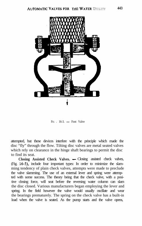
AUTOMATICVALVESFOR THEWATER UTILITY 443
FIG . 16-3. - Foot Valve
attempted, but these devices interfere with the principle which made thedisc “fly” through the flow. Tilting disc valves are metal seated valveswhich rely on clearance in the hinge shaft bearings to permit the discto find its seat.
Closing Assisted Check Valves. - Closing assisted check valves,(Fig. 16-5), include four important types: In order to minimize the slam-ming tendency of plain check valves, attempts were made to precludethe valve slamming. The use of an external lever and spring were attemp-ted with some success. The theory being that the check valve, with a posi-tive closing force, will seat before the reversing water column can slamthe disc closed. Various manufacturers began employing the lever andspring. In the field however the valve would usually oscillate and wearthe bearings prematurely. The spring on the check valve has a built-inload when the valve is seated. As the pump starts and the valve opens,
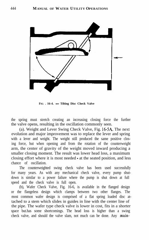
444 MANUAL OF WATER UTILITY OPERATIONS
FIG . 16-4. - Tilting Disc Check Valve
the spring must stretch creating an increasing closing force the furtherthe valve opens, resulting in the oscillation commonly seen.
(a). Weight and Lever Swing Check Valve, Fig. 16-SA. The nextevolution and major improvement was to replace the lever and springwith a lever and weight. The weight still produced the same positive clos-ing force, but when opening and from the rotation of the counterweightarm, the center of gravity of the weight moved inward producing asmaller closing moment. The result was lower head loss, a maximumclosing effort where it is most needed - at the seated position, and lesschance of oscillation.
The counterweighted swing check valve has been used successfullyfor many years. As with any mechanical check valve, every pump shut-down is similar to a power failure where the pump is shut down at fullspeed and the check valve is full open.
(b), Wafer Check Valve, Fig. 16-6, is available in the flanged designor the flangeless design which clamps between two other flanges. Themost common wafer design is comprised of a flat spring loaded disc at-tached to a stem which slides in guides in line with the center line ofthe pipe. The wafer type check valve is lower in cost, fits in a shorterspace but.has some shortcomings. The head loss is higher than a swingcheck valve, and should the valve slam, not much can be done. Any main-

AUTOMATICVALVESFORTHEWATER UTILITY 445
FIG . 16-S. - Spring and Lever Check Valve
tenance requires the valve to be removed from the pipeline.Another variation of the wafer type check valve is the “double disc”
design. This valve employs a hinge shaft which extends through the cen-ter of the valve body on which is attached two spring loaded gates orvanes which are bent back by the flow. Such a valve can never open fully.
(c). Float operated water level control valve, Fig. 16-9, is a directfloat and lever operated valve. The valve position is dictated by the waterlevel. The lowering of the water level causes the float’s weight times thelevered mechanical advantage to physically lift the valve stem open. Therange of water level over which the valve operates is governed by thelever lengths. This direct acting valve is usually limited as to the workingpressure allowed.
(d). Air release valves are often misunderstood and misapplied. Allair release valves fall into one of two categories. It is either a small orificeunit (less than about %“), Fig. 16-10, or a large orifice unit (greater than
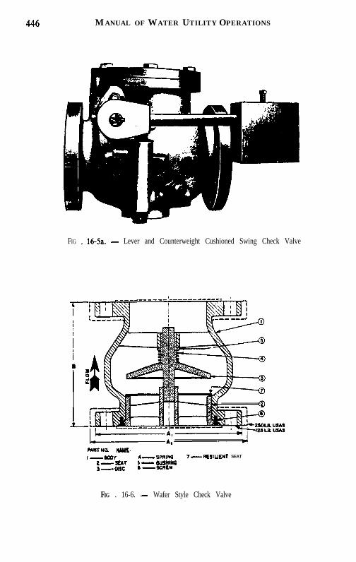
446 MANUAL OF WATER UTILITY OPERATIONS
FIG , 16-Sa. - Lever and Counterweight Cushioned Swing Check Valve
PARYNQ w w &I-WDY 4- SPRlNa T-RESIULNT SEAT
f=EI - WJSHINOa --XRLW
FIG . 16-6. - Wafer Style Check Valve
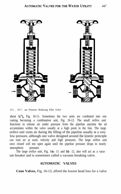
AUTOMATICVALVESFORTHEWATERUTILITY 447
FIG . 16-7. - Pressure Reducing Pilot Valve
about Y2”), Fig. 16-11. Sometimes the two units are combined into onecasting becoming a combination unit, Fig. 16-12. The small orifice unitfunctions to release air under pressure from the pipeline anytime the airaccumulates within the valve usually at a high point in the line. The largeorifice unit vents air during the filling of the pipeline usually at a verylow pressure, although one valve designed around the kinetic principlecan vent air at sonic velocity and high pressures. The large orifice unitonce closed will not open again until the pipeline pressure drops to nearlyatmospheric pressure.
The large orifice unit, Fig. 16- 11 and 16- 12, also will act as a vacu-um breaker and is sometimes called a vacuum breaking valve.
AUTOMATIC VALVES
Cone Valves, Fig. 16-13, afford the lowest head loss for a valve

448 MANUAL OF WATER UTILITY OPERATIONS
FIG . 16-9. - Simple Float Valve
when specified that its passageway is to be bored after assembly. Thecone valve is simply a conical plug in a valve body which rotates 90 de-grees to produce a full unobstructed pipe opening, or a full closed valve.The cone valve is a metal seated valve and all throttling is done by theseats. Fluid dynamic forces must be considered in sizing the operator,similar to the butterfly valve.
The cone valve mechanism is rather complex. The plug assemblymust be lifted more than l/q” before rotation and reseated on each fullopen or full close operation. The use of cone valves has been losing favorover recent years.
Ball Valves, Fig. 16- 14, have gained in prominence as the cone valvepopularity has declined. The ball valve provides a full unobstructed pas-sageway for the fluid but does not require the lifting of the rotor priorto its rotation or the reseating after rotation. It can have metal or resilientseats, however, as with the valves mentioned earlier, the ball valvethrottles with its seat. Controls for ball valves or cone valves can becomeelaborate.
Globe or Angle Valves, Figs. 16- 15 and 16- 16. - Globe or anglepattern valves, in most respects, are self-actuating, therefore, automatic,and operate on the differential area principle by way of a diaphragm

AUTOMATICVALVESFORTHEWATERUTILITY 449
I50 P.S.I.l �LII��l
r01BODYCOVER\W;l?AGE F R A M E
FLOATGASKETC O V E R B O L T SR E T A I N I N G S C R E W S
IO
1:I314i 718I9
FLOAT A R MORIF ICE BUTTONP I V O T P I NR E T A I N I N G R I N GP I P E P L U GFLOAT RETAINERORIF ICE BUTTONLINK
ARM
FIG . 16-10. - Small Orifice Air Release Valve
or piston assembly.Differential Piston Valves, Fig. 16- 17, generally are the most pow-
erful in operation of the designs to be discussed. This type valve employsjust one moving part, the piston which moves up and down to increaseor restrict the flow passageway. The differential piston valve providesfull 100% flow area when open, putting this valve in the exclusive full-ported family with the cone, ball, and gate valve.
The method of operation results from the differential forces pro-duced by the line pressure applied to top and bottom surfaces of the pis-ton. Line pressure enters the valve under the valve piston. The line pres-sure times the area of the underside of the piston produces an openingforce. For example, the area of the underside of an 8” valve piston is over50 square inches. At 100 psi pressure, the opening force is over 5000pounds. The piston, weighing perhaps twenty pounds, is easily lifted withjust a few psi.

450 MANUAL OF WATER UTILITY OPERATIONS
FIG . 16- 11. - Large Orifice Air Release Valve
FIG . 16-12. - Combination Air Release Valve

AUTOMATIC VALVFS FOR THE WATER UTILITY 451
FIG . 16-13. - Cone Valve
FIG . 16-14. - Ball Valve

452 MANUAL OF WATER UTILITY OPERATIONS
AREA X EOUALS PIPE AREAAREA V EOUALS AREA XAREA w EOUALS TwlCE AREA X THREE WAV COCK OR
AUTOMATIC PILOT
OPENINQ FORCE EOUALS PSI TIMES AREA xCLOSING FORCE EQUALS PSI TIMES AREA w-x
GLOBE VALVE ANGLE VALVE
FIG . 16-15. - Globe Valve FIG. 16-16. - Angle Valve
FIG . 16-17. - Differential Piston Globe Valve

AUTOMATICVALVESFORTHEWATER UTILITY 453
[J !- I,_..__.._._.._. --_.-._ ._-
ANGLE VALVE
GATE VALVE~--
T Y P I C A L G L O B E V A L V EiiB-VEE~Will~ -.-.-.
FIG . 16-17a. - Comparison of Valves (50% open)
The area of the upper surfaces of the same piston is much greaterthan the area of the underside of the piston, sometimes twice as much.When equal pressures are applied to both surfaces of the piston, a power-ful closing force results. The large operating forces permit the valve tobe operated in any position - even upside down, and often, under water.Not all differential piston designed valves have a large ratio of areas be-tween the top and bottom of the piston. Valves used for pressure regula-tion may have upper piston areas from about 10% to 15% larger thanthe bottom area.
A unique feature offered by one manufacturer of the differentialpiston valves is the long “vee ports” which, located downstream of theseating surface, can significantly extend valve life plus provide an im-proved flow control characteristic, Fig. 17a. Since “vee ports” are down-stream of the seating surfaces they provide the throttling. Such an ar-rangement extends the valve life significantly, especially when valves arerequired to continuously regulate. Were the “vee ports” to be locatedupstream of the seating surfaces, the resulting cavitation would be im-posed directly on the seating surface, since cavitation occurs directly

454 MANUAL OF WATER UTILITY OPERATIONS
FIG . 16-18. - Stem Guided Differential Disc Globe Valve
downstream of the point of maximum velocity. For severe service, thedifferential piston type valve can be furnished with stainless steel in lieuof the bronze construction. Chrome plating is another option.
These valves have been built in all sizes to 42 inches and are avail-able for most pressures.
Stem-‘Guided Differential Disc Valve, Fig. 16- 18 or floating pistontype valve is a variation of the differential piston valve. It contains a disctype piston and seating member on a center guided stem. This designalso has been around for nearly 100 years and is generally less expensivethan the differential piston valve mostly because of the amount of bronzeemployed.
This disc type valve has a small differential area equal to seal diame-ter on the lower stem. This design does not provide the great operatingforces obtained by the differential piston design and, as a result, the valveis recommended for installation in a horizontal position, which alsowould minimize bearing wear on the small bearing areas.
The piston of the differential disc design valve which provides thepower for the valve operation has the area on the underside of the pistonexposed to the downstream pressure within the valve. The power for oper-ation thus becomes the difference in pressure across the valve (head loss)
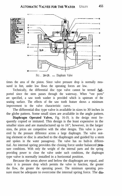
AUTOMATICVALVELSFORTHEWATER UTILITY 455
----- --,,
---... _-__,I,237.
10
87I‘
FIG . 16-19. - Diaphram Valve
times the area of the piston. Since valve pressure drop is normally mea-sured in feet, under low flows the operating forces are low.
Technically, the differential disc type valve cannot be termed full-ported since the stem passes through the waterway. When “vee ports”are specified, a saw tooth washer is provided which is upstream of theseating surface. The effects of the saw tooth feature shows a minimumimprovement to the valve characteristic curve.
The differential disc type valve is available in sizes to 30 inches inthe globe pattern. Some small sizes are available in the angle pattern.
Diaphragm Operated Valves, Fig. 16-19, is the design most fre-quently copied or imitated. This design is the least expensive in thesmaller sizes and are manufactured up to 16”; however, in the largersizes, the prices are competitive with the other designs. This valve is pow-ered by the pressure difference across a large diaphragm. The valve seat-ing element or disc is attached to the diaphragm and guided by a stemand spokes in the water passageway. The valve has no built-in differen-tial. An internal spring provides the closing force under balanced p’res-sure conditions. With only the weight of the internal parts and the springproviding power to close the valve under such conditions, the diaphragmtype valve is normally installed in a horizontal position.
Because the areas above and below the diaphragm are equal, andsince it is pressure drop which permits the valve to function, the greaterthe flow, the greater the operating power. The minimum operating pres-sure must be adequate to overcome the internal spring force. The dia-

456 MANUAL OF WATER UTILITY OPERATIONS
SMALL DISCHARGE - -NEEDLE VALVE
NORMALLY OPEN
FIG . 16-20. - Pressure Reducing Valve
phragm type valve has no “vee ports” or similar feature to improve itscharacteristics; therefore it throttles with its seating surfaces.
An advantage of the diaphragm arrangement is that there need beno packing glands making the valve more suitable for hazardous liquids.A disadvantage results from the flexing and deteriorating effects on thediaphragm, and higher head loss. No valve position indicator stem is fur-nished unless specified.
VALVES AND APPLICATIONS
Of the three basic valve designs briefly discussed, all can be madeto perform virtually all the functions to be described.
@ring regulating operations, such as flow control or pressure regu-lation, a pilot valve, or series of pilot valves, exhaust or admit pressureto the upper surfaces of the piston, disc, or diaphragm to open or closeor position the valve.
Various valve types are described and some of their functions.Pressure Reducing Valves, Fig. 16-20, function using one pilot

AUTOMATICVALVESFORTHEWATERUTILITY 451
FIG . 16-21. - Pressure Reducing with &pass
valve which opens as the valve delivery pressure drops below the set point.Water is exhausted from atop the valve piston, disc, or diaphragm ata more rapid rate than water can enter through a closing speed needlevalve. During throttling operations, an equilibrium is established be-tween the flow entering through the needlevalve and the exhaust throughthe pilot valve stem. Any subsequent movement of the pilot stem willchange this equilibrium, resulting in a repositioning of the main valve.
The pressure reducing valve (PRV) can be made to perform severalfunctions in addition to the control of the valve delivery pressure. Thevalve could have electric solenoid controls, a back pressure control, orreverse flow check, to mention a few. The more severe service require-ments for the typical PRV is at very low flows or large pressure reduc-tions where the delivery pressure is very low. Resulting cavitation can

458 MA N U A L O F W ATER UT I L I T Y OP E R A T I O N S
OVER PRES3URE CONTROLPILOT (TURN HANDWHEEL.CLOCKWISE TO RAISEPRESSURE)
IMPULSE LINE CONNECTED TOINLET THRU STOP VALVE
r NEEDLE VALVE CONlROlCLOSING SPEED
3OOY!t'u G
- STOP VALVES -
NORMALLY OPEN
i.-le. Q-1031 e-1040 MNGES P E R A N S I 816.1
FIG . 16-22. - Globe Surge Relief Valve. _destroy the valve.
A common practice when employing reducing valves where a widelyvarying flow demand is required, is to install a small PRV in a bypassaround the large PRV to handle the small flov&. This small PRV wouldbe set at a higher pressure, perhaps 5 or more psi higher, than the largePRV, Fig. 16-21.
Over Pressure Relief Valves, Fig. 16-22, have the requirement ofopening and relieving to atmosphere or low pressure system any pressuresabove a set point on a control pilot valve. The control of the relief valveis similar to the reducing valve, except the pilot valve is of the oppositesequence and arranged to sense the valve inlet pressure. The over pres-sure setting is generally 10% above the maximum expected system pres-sure, but easily field adjusted. Relief valves are required to open quicklyand close at a controlled rate of speed.
Relief valves are available in many varieties, one of which is the

A U T O M A T I C V ALVES F O R THE WATER UT I L I T Y 459
FIG . 16-23. - Angle Body Surge Relief Valve
“surge anticipator”, Fig. 16-23. This valve is a more sophisticated versionand requires more consideration in its sizing. The anticipator is condi-tioned to open in response to a cause of a surge prior to the pressure rise.The anticipator valve opens fully, waits for the returning upsurge to dissi-pate the energy, then closes at an adjustable rate. This valve also func-tions as an over pressure relief valve.
CheckValves are the most common of all valve types, with probablythe greatest variety of valve types available. The mechanical checkvalves, such as swing check, tilting disc and wafer will not be discussed,but some features available in the automatic check valve designs willbe mentioned.
Typical Power Operated Check Valve. - Standard power oper-ated check valves sometimes called electric check valves or pump controlcheck valves are normally held closed when the pump is “off ‘. Upon en-ergizing of the pump and satisfactory pressure occurring, the check be-gins its timed opening sequence, producing a gradual acceleration of thefluid column. Pressure transients can usually be held to desired limits.A normal shutdown command initiates a gradual valve closing sequencewhile the pump continues to run. The fluid column is brought to a gradu-al rest. Just prior to the final seating of the valve, the valve actuates alimit switch which deenergizes the pump motor,and as a result, there

460 MANUAL OF WATER UTILITY OPERATIONS
FIG . 16-24. - Electric Check Valve
is no excess surging.Many pumps could be brought on line or taken off line in sequence
with a minimum of pressure transients because of the independently ad-justable opening and closing speed adjustments.
In the event of an electrical power failure to the pumps, the checkis directed to close generally at a more rapid rate to preclude excess pumpreversal. On some of the check valves, an emergency closing feature isprovided, permitting a separately adjustable emergency closing speed.
Another useful feature furnished as a standard on some check valvesis the manual operator which provides a means of operating the checkvalve should a solenoid coil burnout occur.
Pump Differential Pressure Sustaining Check Valve is one appli-cation of special pump control check valves, electric check, which arebecoming more sophisticated. This valve employs a pressure sensing pilotvalve of the differential design. Pressure sensing connections are madeto both the suction and discharge sides of the pump. The check valvethen is directed to maintain a pre-selected differential pressure. By main-taining a constant differential pressure, the pump discharge flow rate

AUTOMATICVALVESFORTHEWATER UTILITY 461
can be maintained. The flow is uniform regardless of fluctuations in thepump pressure.
Remote Throttling Feature. - The previous valve arrangementsfunction by sensing the pump suction or discharge pressure. It also ispossible to have a signal originating from a remote location produce athrottling action of the pump check valve. There are several methodsof accomplishing the valve positioning. One means is by an electronicservo amplifier feedback potentiometer arrangement using solenoid pi-lots. Another method is a pneumatic positioner, whereby the valve stillis powered by line fluid.
There are also ways of changing the pressure adjustments of thepilot valves from a remote location, as well as returning a valve positionsignal back to an operator. By a push button arrangement, an operatormay wish to select the valve position manually.
Suction Pressure Sustaining. - In booster pump installations, thepump suction pressure must be assured to minimize starving the pump.Where a booster pump attempts to pump at a greater rate than the initialpump station, pressure switches are sometimes used to shut down thesystem. By employing the backpressure sustaining pump control checkvalve (electric check) with the pressure sensing line connected to thepump suction, the check valve can throttle the pump discharge flowwhenever the suction pressure drops to some pre-selected intensity. Youcan thus assure the pump an adequate positive suction head without theneed to shut down the system.
Discharge Pressure Control. -On occasions, pumps are installedwhere the suction pressure varies considerably. As a result, the pumpdischarge head also will vary. To avoid delivering excess pump dischargepressure into a pressure sensitive zone, the pump check valve can be madeto act as a pressure reducing valve in addition to the normal controlledopening and closing features described earlier. The check valve regulatesa constant pressure into the system regardless of the varying pump dis-charge pressure. It is possible to adjust the control to limit the maximumpressure delivered to the system. In this case, the check valve onlythrottles when required.
Backpressure Sustaining. - In addition to standard functions pre-viously described, a check valve can be provided with a pressure controlpilot valve arranged to sense the pump discharge pressure.
While admitting that any valve that throttles consumes power, andthat variable speed pumps can provide variable pumping rates more effi-ciently, there is an enormous difference in first cost, maintenance, andcomplexity. Also, the throttling requirement of the valve may only be

462 MANUAL OF WATER UTILITY OPERATIONS

AUTOMATICVALVESFORTHEWATER UTILITY 463
temporary or for short durations.The backpressure sustaining feature is useful by limiting the pump
discharge flow when the pump is oversized, or to prevent pump “run-out”such as when one of many pumps discharge into a large pipeline withvery little line friction available, permitting the pump to operate backtowards its head-discharge curve design point.
On well pump installations, it is then possible to prevent excesspumping rates during the periods when well production is low.
The pressure sensing pilot valve will raise the system head curveto any desired point on the pump curve by causing the valve to modulateand maintain that point.
Water Level Control Valves. - Just as the other valves discussed,water level control valves can be provided in a great number of variations.
1. The pilot operated float valve is probably the simplest of waterlevel control valves, Fig. 16-25. The valve is generally controlled by apilot valve locally or remotely mounted from the valve. Some float valvescan modulate proportional to the rise and fall of a specific water levelrange, while others offer a differential control; the choices are numerous.
2. Altitude Valves have been around for more than 80 years, andsome of the first are still in operation. The more common arrangementsare:
(a) Single Acting admits flow into a tank or reservoir and closesat a preset high water level. The flow exits the tank by way of a bypasscheck valve, Fig. 16-26.
(b)Double Acting valves admit water to a tank or reservoir and closeat the prescribed high water level. A reduction of the system pressurebelow the tank height will cause the altitude valve to re-open to permitflow from the tank.
(c) Back Pressure Sustaining altitude valves are usually found onlow level tanks and used to prevent the high rate of filling from droppingthe system pressure similar to a line break. Only the surplus water isthen admitted to the tank.
Altitude valves are available with differential controls for closingat one water level and opening at another. Solenoid controls can overridethe hydraulic controls to close or open the main valve, Fig. 16-36. Whenequipped with a limit switch, the altitude valve can stop the pump whenthe altitude valve closes. A pressure switch is a common method of start-ing the pump at a pre-selected low water level.
It is not possible here to discuss all the altitude valve options, suchas fire reserve, fire demand, and excess flow prevention.
Solenoid Operated Valves, can perform virtually any function
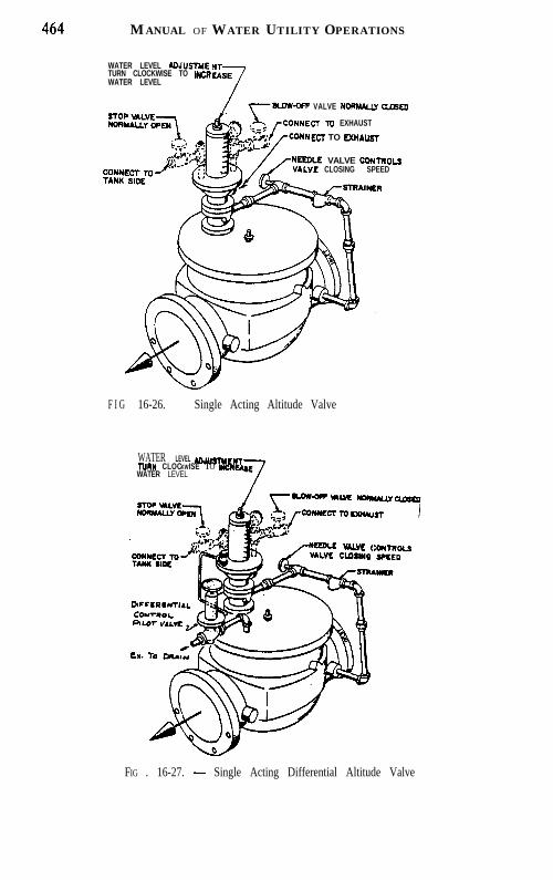
464 MANUAL OF WATER UTILITY OPERATIONS
WATER LEVEL AD.JU.STMETURN CLOCKWISE TO INCRWATER LEVEL
VALVE NORMALLY CU6DD
CT To EXHAUST
ECT TO D(HAUST
VALVE ccwnoLsCLOSING SPEED
F I G 16-26. - Single Acting Altitude Valve
WATER LEVEL lOJUSTWLNTNW CLOCKWISE TO YW)LUEWATER LEVEL 7
Ncm.E VALVC <VALVE CLDSINO
FIG . 16-27. - Single Acting Differential Altitude Valve

AUTOMATICVALVESFORTHEWATER UTILITY 4 6 5
T W O W A Y S O L E N O I DPILOT VALVE. ENERGlZETO OPEN MAIN VALVE
wo wAy SOLENO,D
IPILOT VALVE. ENERGIZETO CLOSE MAIN VALVE
~~- GLOBE BODY
FIG . 16-28. - Solenoid Operated Globe Valve
when properly applied. Solenoid pilots can open, close, or modulatevalves. Energizing or de-energizing the solenoid pilot will exhaust pres-sure from atop the piston, disc, or diaphragm and the valve will open.Reversing the solenoid closes the valve. The opening and closing speedsare adjustable.
The solenoid coils can be provided with manual operators when acoil burnout or power failure occurs. Valves can be made to fail openor closed, or assume other duties on loss of electric signals. When furnish-ed with a feed-back potentiometer, the valve position can be monitoredremotely. Solenoid valves are often controlled by a servo-amplifier whenproportional control is required.
S U M M A R Y
From this brief discussion, it should have become apparent that au-tomatic or self-actuating valves can perform countless services. One spe-cially equipped valve can easily provide the functions of several valves,and experience shows that these valves can perform these functions reli-ably for many years.

CHAPTER 17
INSTRUMENTATION
HUGH G. LeCLAIR, PhD.
Trippe F Controls, Inc.
Purposes and Benefits of Instrumentation. - There was a time whenthe operator’s job was fairly simple. He kept the tanks full of water thathad an adequate chlorine residual, repaired leaks in the lines and keptthe house meters working. If the customers did not complain, he had itmade!
Life is not so simple any more. As a result of environmental con-cerns, the energy crunch, the rapid growth in number of lawsuits, in-creased regulatory pressures from both state and federal agencies, in ad-dition to operating the facilities, the operator has to collect and reportmasses of information and keep it for long periods of time.
One of the principal sources of information is instrumentation, andthat’s what this chapter is about: what it can provide, how the informa-tion can be used, and how to be assured the information is accurate. Prob-lems of selection or maintenance and repair are the concern of the designengineer and the maintenance technician. Your concern is operation.You want to operate your facilities well, provide a reliable source of safewater to your customers, and do this as economically as possible. Instru-mentation can help do this and provide the records and reports that docu-ment the performance of the facilities.
Nine functions of instruments are listed:1. Improve process results by providing accurate data on the incom-
ing and outgoing water and the effects of changes made.2. Provide automatic process control where applicable3. Increase efficiency of energy and chemical use4. Provide alarms when process approaches marginal operating lim-
its5. Provide continuous round-the-clock measurements of *important
variables.6. Provide more complete records with less manual paperwork7. Document compliance with regulatory requirements8. Provide automatic shutdowns to prevent equipment damage9. Provide increased safety
466

INSTRUMENTATION 467
Every instrument in the system is for a purpose. Often that purposeis obvious; if not, the plans and specifications may make it clear. If youare still uncertain, ask questions of your supervisor, the engineer and thesupplier. Unless you know its use, you can not really believe it is impor-tant, and you will not get the benefits provided.
Defined. - In terms of the general description of what instrumen-tation can do, instruments are any devices or groups of devices that:
1. Provide useful information or measurements2. Can act automatically to maintain the process or shut it down
when safety requires, and3. Provide a means for the operator to the process or override auto-
matic control when necessary.By this definition instrumentation can be simple: a pressure gauge,
float switch or even an off-on selector switch. Also, such devices includetransmitters, recorders, and controllers which have been around foryears. Today, computers have been added to the list. They may be usedto gather and record data and print reports. Sometimes the computerkeyboard replaces the selector control switches to start and stop pumpsor open and close valves. Some computers are capable of full process con-trol. Whatever their capabilities, computers are considered a part of theinstrumentation system, which consists of all the devices that togetherprovide the information and the actions listed above.
It may seem strange to include gauges, switches, and control valvesas a part of the instrumentation system. These items usually are pur-chased separately. When there is trouble, however, you learn in a hurrythat they belong here. If a pressure transmitter or receiver fails, thegauge is your back-up to provide operating data. If a pump will not run,the selector switch, even the one in the starter panel, can be the problem.If a flow control loop hunts or otherwise acts up, the trouble can be inthe valve operator.
Since a control loop was mentioned this is a good time to define it.No matter how large or complex the system, it is made up of individualsubsystems, each of which concerns a single measurement. The subsys-tem itself will have components which make up that control loop. Forexample, consider an elevated tank which is kept filled from a two-pumpbooster station; the pumps are controlled automatically from the mea-sured tank level. The control loop includes all these devices:
LT - level transmitter, measures level (actually it measures pres-sure, but the level equivalent is used and sends a signal representing thelevel to
LIR - level indicator-recorder at the pump station which displays

4 6 8 MANUAL OF WATER UTILITY OPERATIONS
the level measurement on a dial (I - indicator) and marks it on a chart(R - recorder). In the recorder are the
LS - level switches which are set to start and stop the pumps at ap-propriate levels. Also included is the
LI - level indicator, at the tanks, which can be observed locally. Thiscould be (1) an indicator built into the transmitter in which the transmit-ter would be designated LIT; (2) the target on the.outside of the tank;or (3) a separate pressure or altitude gauge connected to the same pres-sure tap. Even if the gauge is not installed, it is a good idea to make provi-sion to connect a gauge for test purposes.
The low level cutoff switches are normally a part of the loop for theground storage reservoir which starts with a different measurement.
The pump loops can be controlled from both tanks. In this simpleexample it is discovered that the “system” involves three control loopsfor: (1) the elevated tank, (2) the ground storage reservoir, (3) pumps.A diagram can be drawn for each loop and each loop is assigned its ownnumber.
At this time, it is appropriate to get acquainted with some otherterms:
Analog is a signal which can vary continuously from zero to maxi-mum. It can be displayed on a dial or a chart. When discussing measure-ment we usually are talking about analog signals. In the example above,LT, LIR, and LI are analog devices.
Discrete is a signal which basically represents a “yes” or a “no.”There are only these two states. All switches and lights are discrete de-vices. The LS’s in the example are discrete devices. The settings can bechanged and they operate from the analog signal but their output is al-ways discrete. All the switch can say is “yes, the level is higher than thesetting” or “no, it is not”.
Digital. Thanks to computer technology it is easy to represent thecurrent measured value of a variable in digital form. Nevertheless, thesignal coming in is continuous; that is it is an analog signal. It is convertedin the readout device by an analog to digital (A/D) converter so thatthe display is in digits instead of a pointer moving across a scale. Thereare digital signals as well as analog signals but these are at present pecu-liar to telemetry and computers, which will be discussed later.
Status is the present state of a discrete signal-pump “on” or “off,”pressure “high” or “low”.
There is another set of terms found in instrument specifications op-eration and maintenance manuals. These are important in that they indi-cate what is expected in performance or calibration.

INSTRUMENTATION 469
Range is the minimum and maximum values between which limitsthe instrument can measure, that is, O-1,000 gpm, O-50 psi, O-135 feeton an elevated tank.
Span is the difference between the upper and lower limits. Usingthe same examples, the spans would be 1,000 gpm, 50 psi, and 135 feet.
Accuracy is the uncertainty of the reading; that is, how close is thereading to the actual value. Here is where the arguments begin. Thestatement, “This instrument has 1% accuracy,” is meaningless. Thequestions are 1% of what, and over what range? A full, precise accuracystatement would be something like this:
Accuracy, + 0.5% of (actual reading) (full scale) (span) for read-ings between maximum and (l/4)( 1 /S)( 1 /IO) of the maximum. Takingthe flow measurement first, a table of the maximum uncertainty at vari-ous flow rates follows:Note the difference between the expected results, especially how the ran-geability part of the statement results in no guarantee of accuracy atsome of the lower flow rates.
Similarly, for the elevated tank transmitter considering only the dif-ference between statements based on full scale and span and assume 10: 1rangeability, as this is generally typical. The difference here primarilyaffects the amount of “cushion” remaining to keep from running the tankover.
Repeatability. How near the reading will be to the same value whenmoved away from and then returned to the same input conditions. Thisis not the same as accuracy. Considering the elevated tank transmitteragain, the repeatability might be expected to be + 0.2% of full scale,or + 3- l/4 inches. The repeatability means that if the transmitter is cali-brated by running the tank over, the reading will be within 3-l/4 inchesof full scale each time the tank is filled to the overflow. Obviously, goodrepeatability means that the “cushion” can be reduced and still not over-fill the tank.
Applications in Water Utilities Operation. - Not too many yearsago, instrumentation for water utilities was limited primarily to flow,level and pressure measurement, and automatic control and monitoringof pumps and valves. Today, the scope has enlarged. First, the varietyof reliable instruments available at reasonable cost has increased mark-edly. Improved technology and potential demand have combined to bringsuch devices into the market place. The huge increase in energy costsplus corresponding cost increases in all areas of operation, maintenanceand repair have made instrumentation an alternative to manual opera-tion. Also, regulatory requirements call for the reporting of new operat-
4 7 0 MANUAL OF WATER UTILITY OPERATIONS
ing and water quality variables, and corresponding instrumentation isnow available. Reliable on-line instruments are on the market to measurethese variables: (a) processes: flow rate, level, pressure, temperature, pH,turbidity, chlorine residual; (b) equipment performance: running times,speed, current, voltage, power, position; (c) through use of monitors ofprocesses and equipment performance, the following processes can becontrolled: flow, level, pressure, chemical feed for pH, chlorine residualand others; (d) equipment can be controlled including safety shutdowns:pumps, valves, basin equipment (flocculators, clarifiers, etc.) overtorqueshutdown, overcurrent/undervoltage shutdown, vibration shutdown,bearing temperature shutdown; (e) alarms for unsafe conditions include:chlorine gas leaks, ammonia gas leaks, electrical ground faults.
Data can be collected, collated and printed for operating and main-tenance reports. This is one of the major roles of the computer. Someinstruments, particularly flow measuring devices and control valves, aredifficult to retrofit into existing facilities. Many others can be installedwithout major difficulty. One responsibility of an operator is to be alertto the possibility that an instrument could pay for itself in increased effi-ciency and to recommend its consideration and the expected benefits.
Installation and Calibration. - General considerations. Instru-mentation can provide many benefits to the user in improved operationand efficiency. There is a condition, however; instruments must be reli-able. If not they provide wrong data and cause wrong decisions. Thenyou decide you can not trust them, so you ignore them and lose the poten-tial benefits. In this section the benefits of your existing instruments willbe discussed.
It should be assumed that the equipment is basically good, meaningthat if it is on the market, it must have worked somewhere. There is thewarranty protection from the contractor and both the designer’s and themanufacturer’s reputations on your side. They will all work with you butthey will need your cooperation.
The Problem. - First, read the manufacturer’s literature, the spec-ifications and the instructions. Compare them to the requirements as youunderstand them. It may be that you are expecting more than the equip-ment is designed to do. Unless you can show that there is a misapplica-tion, that the equipment can not fill the actual job requirements, youwill be expected to live with what you have. If you think there is a misap-plication, you should talk to your design engineer.
So far in this section we have obviously been talking about a newproject and new instrument selection. The operator is not in control ofthat phase, although it is hoped that he had some input. Now turn to

INSTRUMENTATION 471
the installation conditions, which the operator can do something about.Installation Guidelines. - It would be a wonderful world if every
instrument were installed exactly the way the manufacturer intendedit to be. In practice many installations fall short, sometime way short,of the ideal. Improvements, however, to almost any installation can bemade for little cost in materials and your own labor. First, however, youmust give some thought to what is to be accomplished.
Read the instructions. - The manufacturer wants the equipmentto work. The installation instructions will tell what is needed for goodperformance. It will probably be idealistic - we would all like to seeevery instrument in a clean, air-conditioned, well-lighted space - butit establishes a goal. Common sense and maybe a phone call to the willhelp adapt the recommendations to your situation. There are some gener-al rules regarding location, mounting, piping and wiring.
Location and mounting. - Accessibility for calibration and servic-ing is needed. Allow enough room for two people to stand without bum-ping into each other. Also, the instrument should be mounted at a conve-nient height and orientation. It is hard to work squatting or on a ladderor going by feel because the adjustments are on the back toward the wall.Always mount instruments level. Float type instruments will be put ina bind if not set with the cable plumb. Differential pressure units arecalibrated with the two pressures exactly equal at zero. When co?sideredthat they are measuring differences in inches, a fraction of an inch differ-ence in the height of the two inputs can cause significant errors at lowflow rates.
Environment. - Instruments and personnel need protection fromweather, dust and dirt, excessive heat and cold, corrosive gases and li-quids, and water. For example, if any instrument must be outdoors, arain shield can be installed. Preferably, a small wood shelter with a dooropening toward the best bad weather direction and capable of beingblocked part way open (for illumination) may be feasible. If an instru-ment must go in a vault or manhole, it should have a solid slab to standon and a small sump pump to remove water. Provide for heating in coldweather, a space heater, not just heat tracing on small piping. If thereis a power failure the lace heaters do not have enough of a heat sink toprevent freezing for more than a few minutes.
Piping. -Most pressure instruments require a connection of smallpiping to transmit the pressure from the line tap(s). The lines should beas short and as straight as possible with a constant slope from tap to in-strument. If the instrument is at the high end, air bleeds should be in-stalled at the instrument. Somehow air always gets into these lines and
472 MANUAL OF WATER UTILITY OPERATIONS
must work its way back into the process line or to the bleed valves whereit can be vented.
Valves in these lines should be selected on the basis of their function.Those at the instrument are usually involved in calibration and needlevalves are preferred because they can “ease” the pressure off and ontothe instrument. At the line taps sand, corrosion products, etc., may re-quire coding out. Valves with clear, straight ports (gate, ball, corporationcock) are best.
Wiring. - Always ground the instrument case to protect againstelectrical shock. Use a ground wire. Do not trust the piping to providethe ground even when it is copper. If instruments use 115~ power theynormally have just one fuse. Make sure the fuse is on the hot wire andnot the neutral.
Electronic instruments are susceptible to voltage surges on the pow-er lines as well as on the signal lines and must be protected. A metal-oxide variator (MOV) is inexpensive ($263) and works well for mostsurges (in this area nothing is 100%). Connect it the power terminals.
Signal line transient protectors are more expensive ($40 and up),but are desirable if there is a long signal line, especially if the line is notin metal conduit. The line itself should be a 100% shielded pair withshield tied to ground at one end only. There does not appear to be anyconcensus as to which end to ground the shield. Take your pick but beconsistent in your plant. Either put all shield ground at the panel or allat the field instrument.
Provisions for calibration. - As we have already said, an instru-ment that is out of calibration is worse than no instrument at all; there-fore calibration checking should be standard procedure with regularschedules as well as additional checks whenever an .instrument’s per-formance is suspected. The installation should include provisions tocheck calibration while the instrument is still in service if possible.Pressure, or differential pressure instruments, should have test connec-tions in the piping adjacent to the instrument. These consist of a tee anda valve so you can connect a test gauge or manometer without disturbingthe piping. There may be a gauge already in place serving as a local indi-cator. Do not trust it for calibration! Use a test gauge for the calibration.You can put it back afterwards if it shows to be correct. If not, it shouldbe adjusted, repaired or replaced.
Calibration Checks. - Proper instrument calibration at start-upand following repair is a task for an instrument specialist. He has thetraining, experience and special tools required; and he has specializedtest equipment which represents an investment of several thousand dol-
INSTRUMENTATION 4 7 3
lars. Nevertheless, there is much the the operator can and should do witha few devices costing only a few hundred dollars, to check calibrationand possibly make minor adjustments to correct small drifts in the cali-bration. These are particularly important if you use contract service. Youcan save expensive emergency calls and greatly reduce instrument downtime.
A calibration check involves providing a known input to an instru-ment and measuring its output. Tables are available with formula whichrelates input to output. Whether or not the instrument is working correct-ly can be determined and minor adjustments can be made.
To make such checks for the most common types of inputs (level,pressure, differentials) and outputs (pneumatic, electronic, pulse widthand pulse rate) certain equipment is needed.
Level/depth input. - A tape or measuring rod and a referencemark is needed. The mark is the point from which the measurement ismade. Normally the true zero point in inaccessible. Either it is too deepor it may be arbitrary. There is a point on the opening to the tank thatcan be established as being a precise distance above the zero or the fullscale point. Start from there and compute a reading. Consider, for exam-ple, a reservoir with a hatch on top. By running the tank full to overflow,you can mark a point on the side of the opening as being “X” inchesabove the full scale point (presumably the overflow point). Then, when-ever calibrating, measure from the mark to the water surface, subtractdistance “X”, and what is left is the distance down from full scale. Ob-viously, the reference mark should be scribed, scratched and/or paintedso it will last, and the correction must be recorded in a permanent file.
Pressure input. -A good test gauge with tubing and fittings to con-nect to the test point are required. Do not screw the.gauge into the gaugecock every time you use it. That is wear the gauge does not need. Remem-ber when measuring water pressure the gauge must be at the same eleva-tion as the instrument to avoid error. Again, a reference mark or a hookin the wall on which to hang the gauge will insure that your measure-ments repeat.
You may want to simulate a given input that is different from theactual pressure. To do this, use air pressure from a small compressor witha storage tank and feed through a pressure regulator. Pressure capabilityof 100 psig should be adequate for almost any instrument, and a compres-sor can be handy for many other purposes.
Differential pressure input. -A manometer is used to measure ac-tual inputs, but you do not have to buy one. They are pretty fragile forfield use, anyway. You can make one from a roll of clear plastic tubing

474 MANUAL OF WATER UTILITY OPERATIONS
with fittings to connect to the test tees on the pressure lines. A yardstickor tape measure will provide the measuring scale. Caution (l), make sureyour scale is truly vertical when you make readings. Check it with a levelin two directions at right angles. Caution (2), the total length of tubingmust be sufficient to leave the section filled with air longer than the dif-ferential you want to measure. Since the air will compress, you have toallow for this. For example, if the line pressure is 100 psig, a loo-footlength of tubing filled with air at 0 psig will have the air compressedinto only about 12ih feet, or 100 inches, when you put the line pressurein. Also, work the tubing to eliminate air bubbles or you will get screwyreadings.
To simulate inputs is easier. Differential pressure devices measuredifference only. Cut test pipes out of copper tubing (to repeat an inputmany times) or connect a roll of clear tubing to the high pressure sideand fill it to the desired height. Again, it is critically important to mea-sure true vertical height. A machinist’s tri-square and machinist’s levelmay be used to check this.
Pneumatic outputs. -The general standard for pneumatic instru-ments is to use a signal range of 3 to 15 psig = 0% and 15 psig = 100%signal. The same test gauge mentioned earlier may be used. A O-30 psiggauge with 0.1 psig divisions is recommended. Air supply and regulatorfor simulating inputs to a receiver or controller would be same as de-scribed above.
Electronic outputs. -Most instruments require a 4-20ma DC cur-rent signal, with 4.00 DC = 0% and 20.00ma DC = 100%. There areother ranges in such such as 1-5~ DC, 0- 1Ov DC, 2- 1Ov DC, and for cer-tain special types ranges as low as 0- 1 ma DC and O-50ma DC. Fortunate-ly, there are many meters on the market, often called multimeters, thatwill measure many electrical quantities, including DC volts, AC volts,DC current, AC current, and ohms over several ranges each. Cost in-creases with the level of accuracy desired, especially on the DC currentscale. For general purposes of calibration checking, 1% accuracy on theDC current scale is probably all right. Usually, the DC volt scales arethe most accurate. Manufacturers often recommend a 0.1% precisionresistor that can be inserted into the signal loop so that volts can be readon the current signals. Using Ohm’s law to make the conversion, E =IR, and bearing in mind that lma - l/ 1000 amp, the fomula is:By using a 250 ohm resistor, E will be l-5 v DC for the common 4-20maDC signal.
If a receiving instrument is available (or you have a buddy to helpyou), check the receiver specifications for its input resistance and use

INSTRUMENTATION 475
that value as above.To simulate inputs to receivers a current/voltage source is needed.
Since these are fairly costly the transmitter signal which can be changedas was discussed under inputs can be used to measure the incoming signalwith the voltmeter and check the receiver reading. At least it can be de-termined if the receiver is tracking its input. If not, it is the instrumentman’s problem, but you have isolated the problem for him so he can re-pair it faster.
Pulse width outputs. - These occur in telemetering applications.Basically, the transmitter input is converted into a pulse of varyinglengths of time. A typical example is of a transmitter with a 15secondcycle (the signal repeats every 15 seconds) and a pulse width that varieslinearly from 0 seconds at 0 input to 13.33 seconds at 100% input. Thetransmitter has a switch that closes and opens to create the pulse widthsignal.
For proper calibration, a special timer or calibrator is required cost-ing several hundred dollars. A pretty good calibration check can be madewith a hand-held timer. Press the start button when the switch makesand stop it when the switch opens, then read the time. The instrumentman does not use it because it is not accurate enough. For the signal de-scribed, that 2-3s of full scale, it is good enough to tell that the instru-ment is working, but not close enough for adjustments.
Pulse rate signals. - These also occur in telemetering applications.Usually the signal originates in a propeller or turbine meter, where arotating member operates an electronic switch. Standard output for mostmeters is O-20 pps (pulses per second). It is an awkward range to check.The high end is too fast to count; the low end is below the range of theless expensive electronic counters or frequency meters. Fortunately,there is no calibration per se. The rate is tied to the propeller. The receiverusually has an LED which blinks with each pulse. You can eyeball itto see if the pulse rate is present and if it is steady. If it appears erratic,pass the word to your instrument man,
Summary. - Following is a list of items we have mentioned. Youwill probably have many of them or can acquire them as supplies:
1 Test gauge, O-60 or 0- 100 psig range 6” dial1 Test gauge, O-30 psig (for pneumatic systems,
primarily)1 Air pressure regulator, 60-100 psig maximum1 Air pressure regulator, 20 psig maximum (for
pneumatics)

476 MANUAL OF WATER UTILITY OPERATIONS
1 Air compressor, 100 psig, with storage tank1 lOO-foot roll clear plastic tubing, L/4” or 3/g” OD1 lot tubing fittings to fit above and connect to
instruments or lines, l/g” through %” NPT1 20’ measuring tape1 metal yardstick (easier to use and more divisions
for differential pressure (d/p) measurements1 (or 2) machinist’s level1 machinist’s tri-square1 multimeter (volts, ohms, amps/ma). Once you have
the meter, you can consider accessories such asclip-on amp leads to check motor currents.
1 hand-held timer (not sweep hand stopwatch)1 pocket calulator, with a square root key and memoryTo make minor adjustments small tools will be needed.1 set jeweler’s screwdrivers1 set small Allen wrenches1 set multi-spline (fluted type) wrenches, 4 spline and
6 spline1 set small socket wrenches or open-end wrenches
Some manufacturers furnish some of these, especially the wrenches,in sizes to fit their instruments. It does not hurt to have spares, becausethe originals are easily lost.
One last item, a tool box and carrying case and keep these itemsout of the normal tool storage.
Level Measurement. - Storage tanks are the cushion betweensudden demands such as fires, line breaks or outage of production capa-bility. Knowing how full your tanks are and whether they are gainingor losing is very important to your operations.
Float-Operated Instruments. - These are direct devices and con-sist of a float on the end of a tape or cable which passes over a pulleyto a counterweight on the other end. The counterweight is heavy enoughto keep the cable taut, but not to raise the float without the buoyancyof the water under the float. As the water rises and falls the float moveswith it and the pulley turns.
In its simplest form, a pointer on the end of the pulley shaft turnswith the pulley an’d indicates the water level on a marked dial. This isa float gauge. In a sense, everything else used in a float-operated instru-ment is trimming. In using float and counterweight cables over separatepulleys, the counterweight pulley may be smaller so the counterweight

IN.sTRLJMENTATI~N 4 7 7
travels may be only 1% inches for each foot of float travel. The pulleyshaft may operate a gear train or lead screw so the pulley can make manyturns while the pointer makes only l/2-3/4 turn.
Instead of a pointer the pulley shaft may be linked to a pen armproviding a chart record, or it may operate a mechanism that will pro-duce a pneumatic, electronic, or pulse width signal so the chart recordcan be located in a panel. Also, the pulley shaft may have a set of camsthat operate switches. This provides a float switch or float controller.
In a motion-balance device the motion of the float is balanced bythe buoyancy of the water. Every instrument requires some kind of bal-ancing, whether it is a spring, pressure bellows, or other. Without thebalance the mechanism would go to one extreme or the other like aswitch.
Keep the motion-balance principle in mind because of the implica-tions for calibration and maintenance. By definition, something movesand that motion can be interfered with, causing the instrument to be in-accurate. The interference can be an obstacle, something that physicallyprevents movement. Instruments are sometimes improperly assembledso that the mechanism hits the side of the case. On a float-actuated de-vice, tuberculation on the inside of the float well or ice on the cable aretwo common causes of failure. Another common interference is frictionin the bearings or pivot points. This is called binding. Instead of movingfreely, the mechanism sticks until the unbalance is great enough to over-come the friction. The motion and the chart record is jerky instead ofsmooth.
Having recognized the symptoms, the cure is obvious. Remove theobstacles and do what you can to prevent their recurrence. To eliminatefriction, keep the mechanism clean and lubricated. Dust and dirt willcollect in lubricating oil if it gets into the case. If you clean an instrumentand find it soon gets dirty, look for faulty door gaskets or unplugged open-ings and plug them. Keep the cover secured on the case. This is perhapsthe most common source of trouble. Finally, keep spare cable on handto restring a float-operated instrument as soon as cable kinks or fraysoccur.
Pneumatic transmitter mechanisms - motion type are producedby a device that will take the input motion and output a 3-15 psig airsignal that is in line with the input. This is accomplished by using aflapper-nozzle system.
The flapper is linked to the input motion. The nozzle is fastenedto an expandable bellows and spring assembly. The output air pressure

478 MANUAL OF WATER UTILITY OPERATIONS
is applied to the bellows so the nozzle will move as the pressure changes.When everything is in balance the flapper is not quite in contact withthe nozzle, so that air fed to the nozzle will flow out.
Now suppose the float moves up. The flapper will move closer tothe nozzle - if the motion is fast enough it may touch it, blocking thenozzle. Pressure behind the nozzle builds and that pressure, fed to thebellows, will cause the nozzle to move away from the flapper. Soon thenozzle-flapper separation is back to normal, but at a different position,and the output pressure is at a new higher value. If the float moves down,the flapper moves away from nozzle, pressure drops and brings nozzleback near the flapper. That is basically the system. A booster in the sys-tem function as a sort of amplifier to move air in and out many timesfaster than the nozzle by itself can do because of its small size. The boost-er does not change the principle of operation. It just speeds up the re-sponse to changes.
Actually, the nozzle pressure (about 9 psig) and the nozzle-flapperseparation will change slightly as the output changes between 3 and 15psig; but the changes are too small to be significant. If no separation ora large gap between nozzle and flapper can be observed, report it to yourinstrument man as part of the trouble report when the instrument fails.Since this is a motion-type instrument, cleanliness and lubrication areimportant.
Electronic transmitter mechanisms, motion type. - The generalprinciple is that the input motion causes a change in an electrical inputsignal. The electronic board amplifies the input and regulates the outputcurrent. Repair of a failed board is the technician’s problem. If you canlearn to substitute a spare board and adjust zero, you will save down timeand operating problems.
On a float-actuated transmitter, the float moves the wiper of a po-tentiometer to change the electrical input (a DC voltage) to the board.Use a meter to see if that voltage changes smoothly as the float is raisedand lowered. This may isolate the source of the problem. Cleanliness andlubrication are .important as always.
Pulse width transmitters are inherently motion-type systems. Theyproduce an output that is a switch closure of varying duration.
The mechanism consists of a rotating cam and a switching mecha-nism actuated by the cam. The input motion positions a rate arm acrossthe face of the cam and the cam shape determines the duration of theswitch closure. A significant feature of the pulse-width mechanism isthat the cam can be shaped to produce outputs that are non-linear withrespect to the input motion. Many flow measuring devices are non-linear.

INSTRUMENTATION 479
The cam provides an excellent way of linearizing the output signal.Cleanliness and lubrication are critically important to pulse-width
mechanisms. In addition to the moving parts already mentioned, thereis a motor, cam, rate arm and switch, all of which operate almost 6,000times per day on the most common 15second cycle. The mechanismshould receive regular visual inspections for wear and deterioration. Awobbly motor shaft or an oil leak around the shaft indicate a shaft re-placement or the rotor portion is needed. If readings are erratic, particu-larly in colder weather, check the time cycle. Motors will run slow, espe-cially when cold thickens the oil in the motor rotor. If the cycle is any-thing more than 15 seconds replace the rotor. Replace the switch if themercury inside loses its shine.
Ultra-Sonic Level Gauges are relatively new instruments whichhave found a ready market because there are no moving parts to cleanand maintain, and only the transducer need be located on the top of thetank with special cable connecting it to the electronics package up to1,000 feet away.
The principle of operation consists of a short pulse of sound firedfrom the transducer to the water surface. The pulse bounces back andis received by the transducer. The electronics measures the time intervalbetween pulse and echo and calculates the distance based on the knownvelocity of sound in air.
The frequency of the pulse is above the audible range and the pulseis repeated several times per second so the measurement can be consid-ered as essentially continuous. Internally the electronics must be digital.The result of each measurement must be stored as a digital count andconverted to an analog signal, 4-20ma DC or corresponding voltage, fortransmission. Converters are available for a pneumatic, pulse width, orpulse rate signal.
Mounting of the transducer is critical to good operation. It mustbe horizontal. Also, problems may arise if located on an existing stillingwell where an old float instrument is being replaced. The beam spreadsout about 5 degrees and could produce echoes off the pipe wall.
Temperature compensation also is important. The velocity of soundin air changes significantly with temperature. Units are usually tempera-ture compensated, but remember that what is measured is the tempera-ture of the transducer. Anything that could cause the transducer temper-ature to be significantly different from the air path temperature is boundto cause some reading error.
There is not much the operator can check on these devices. If themeter verifies no output, listen to the instrument and the transducer. Of-

480 MANUAL OF WATER UTILITY OPERATIONS
ten a small click can be heard each time a pulse is transmitted. If thereis no pulse your technician should look at the pulse generator circuit.
PRESSURE MEASUREMENTS
Motion-Balance Units. - The most common pressure measuringinstrument is the pressure gauge. Like all pointer-type indicators, it isa motion-balance device. Better gauges have linkages and gears whichprovide range adjustments. Zeroing is usually accomplished by reposi-tioning the pointer on its shaft. Recalibration of good quality gauges isa job for your technician or the manufacturer. Low-cost gauges are usu-ally discarded rather than repaired.
With the exception of the lowest pressure ranges which require adelicate diaphragm or bellows device, most motion-balance gauges andtransmitters use a Bourdon tube sensor. A Bourdon tube is a coiled orpartially coiled hollow, flat tube which tends to straighten when a fluidunder pressure is applied to the inside. The balance is the “springiness”of the metal tube, which tries to stay coiled.
The same motion which moves a gauge pointer can position any ofthe transmitters discussed to produce pneumatic, electronic or pulsewidth outputs. There is one difference when electronic output is desired.A Bourdon tube does not provide enough force to turn a potentiometershaft. It is necessary to interpose a very low input force device, usuallya linear variable differential transformer (LVDT) which will convertmotion to electrical voltage. The remainder of the instrument is similarto the previous description of electronic transmitters.
Force-Balance Devices show little observable movement in con-trast to what has been discussed. Instead of the device moving to a newposition with each input change, the output signal is fed back in sucha way as to offset the attempted motion.
In the flapper-nozzle suppose that instead of letting the flappermove visibly things are arranged so that the output signal counteractsthe flapper movement. The nozzle can be fixed in place and the flapper(armature) is allowed to move only the few millimeters required tochange the nozzle pressure and the booster section pressure. When thearmature moves closer to the nozzle, the output pressure goes up. Thispressure increase in the balance cell cause the armature to back off untilthe system is back in balance. Similarly, a decrease in input pressuremoves the armature slightly away from the nozzle until the decreasingoutput (and feedback) pressure allows it to move back into balance.
Although there is some movement, it is small. The armature is held

INSTRUMENTATION 481
in place by diaphragms which seal the various sections. Problems stemfrom: (1) dirty air, a no-no in all pneumatic systems; and (2) accumula-tion of dirt around the nozzle. Keeping the air filters and nozzles cleanwill prevent trouble. Electronic transmitters that use an LVDT will usethe same feedback principle, but the forces will be magnetic instead ofpneumatic pressure. The instrument remains at or near a single pointas a result of the input change being offset by a force created by the out-put signal.
Bubbler Systems. - Certain level measurements are awkward foreither float or pressure instruments. Small level ranges, less than threefeet, are commonly solved by the use of a bubbler, a small tube insertedinto the pipe or channel through which a small, steady flow of air ispassed. The pressure in the bubbler line will be equal to the water depthand this pressure will be the same regardless of the height of the linebecause the fluid is air instead of water. This pressure becomes the inputto the high side of a differential pressure (d/p) transmitter, which canthen provide a standard pneumatic or electronic signal proportional tothe measured level.
The bubbler transmitter is a special device that will feed a constantair flow regardless of the pressure at its output. This is important becauseair will have friction loss as it flows through the tubing. If the flow ratechanges with the level being measured, the friction loss changes and af-fects the measurement. A constant air flow produces a constant frictionloss and can be corrected by the d/p transmitter. A good bubbler hasa rotometer to measure the air flow. The flow should be noted regularlyand adjusted to the original flow as necessary.
Flowmeasurement is perhaps the most important and the most mis-understood measurement in the water works industry because flow met-ers determine the revenue that pays the bills. The misunderstandingcomes from the fact that flow is a hydraulic phenomenon that tends tobe ignored by instrument specialists.
Flow is a measure of the volume of water flowing in a given timepast a specific point in a pipe or channel. The basic formula is
Q = A x V
where Q is the flow rate, A is the cross-sectional area of the pipe at thepoint of measurement, and V is the velocity of the water flow at thatpoint. The problem is in determining the velocity. Every flow meter isbased on certain assumptions about the velocity profile, within the pipecross-section. Most of the time these assumptions are not exact. They

4 8 2 MANUAL OF WATER UTILITY OPERATIONS
may be wrong.Because of viscosity of the water and friction at the pipe walls, there
are many different velocities at different points, highest near the center,and low or zero near the wall. Downstream of a bend or elbow, the veloc-ity will be higher on the side at the outside of the bend. Flow throughtwo elbows at right angles to each other, will produce or swirl, that is,the flow tends to spiral down the pipe and the direction of flow at a localpoint is not parallel to the pipe axis. These examples indicate that themeaningful average velocity of the flow can be difficult to measure.
Differential Producers get their name from the fact that they havetwo pressure-sensing points and the difference in the two sensed pres-sures relates to the flow rate. This relationship is based on the law ofconservation of energy. Energy can be changed from one form to another,but cannot be created nor destroyed. The first device invented andmarketed to measure flow rate in large pipes is the Venturi tube.
The Venturi consists of an inlet section followed by a throat sectionof smaller size. At the inlet there is a certain velocity and a certainamount of kinetic energy (K.E.) from the motion of the fluid. It also haspotential energy (P.E.) because it is under pressure. P. E. is directly relat-ed to the pressure which can be measured with a gauge. We know wateris non-compressible; therefore, to obtain the same flow rate through asmaller area, the velocity has to increase. This requires more kinetic ener-gy which comes from the potential energy causing a pressure drop atthe throat. If the difference in the two pressures is measured betweenthe inlet and the throat, the velocity can be calculated and therefore theflow rate. The formula from the ASME Fluid Meters Handbook follows:
Q = C x K x h w
Q = flow rate in gpm or MGD.hw = differential head in inches of water, given by the manufactur-
er. Actually, hw = pressure differential in psi x 2.3 1 (to getfeet of head) x 12 (to get inches of head).
K = a meter constant, resulting from various conversion factorsplus the shapes of the tube, specifically the ratio (beta ratio)between the diameter of the throat and the diameter of theinlet section. It is a constant for any given tube.
C = a fudge factor. If you run a volumetric check, you will alwaysfind that the calculated Q is larger than your actual measure-ment.

INSTRUMENT ATION 483
For the original Venturi tube and its descendants, C = 0.98 approxi-mately. There are other producers on the market with “C’s that rangedown to 0.6. In a sense “C” is a measure of how near the meter is tobeing perfect (C = 1). If a volumetric check of a meter shows a signifi-cant error, return it to the manufacturer with a piping sketch of the in-stallation. The manufacturer may be able to revise the original “C”based on the actual piping configuration. If the original “C” is correct,you can use your homemade manometer and trust the measured differen-tial to check your instrumentation.
The Venturi tube has been the standard measuring device in hy-draulic labs since the turn of the century, including the calibration labsof other types of meters. A principal reason for its success is the flowconditioning that takes place when the flow is squeezed through thethroat. The smaller the throat, the greater the conditioning, i.e., swirlis reduced, velocities across the pipe become more uniform. If you havea choice, purchase the smallest throat size you can stand for the differen-tial and head loss.
Differential Pressure (d/p) Transmitters. - A differential pres-sure transmitter is one which produces an output proportional to the dif-ference between two pressures. Observe the flow formula. Flow rate, Q,is proportional to the square root extractor to get a reading that is linearwith flow. With these two concerns in mind, look at the instruments avail-able.
Motion balance instruments have been available for many years.First and oldest, is the mercury manometer-type which is basically afloat-operated instrument with a cast iron float riding on a column ofmercury. The float motion comes out of the well through a stuffing boxwhere it actuates a motion balance type transmitter very much like thosealready described. The mercury and the iron float combined provideenough power to overcome the usual friction effects so that transmittersare capable of providing good accuracy over wide flow ranges. One per-cent of actual rate of flow over 1O:l range is fairly common and widerflow ranges are available.
There has been much concern over the use of mercury in instru-ments used on potable water. Keep in mind: (1) mercury is totally insol-uble in water. If you dumped all the mercury in an instrument into apipeline it is doubtful any water analysis would show any trace; and (2)mercury is so heavy it will not suspend in the water and be carried alongby the flow to any user. The EPA has issued guidelines for the use ofmercury in instruments. Basically, they caution you to keep it off yourskin and keep it under water so that you will not breathe the vapors when

484 MANUAL OF WATER UTILITY OPERATIONS
it volatilizes. The biggest danger is from spilled mercury that has notbeen cleaned up.
The other type of motion balance device is the d/p cell that has atorque tube output. The unit has two bellows connected so as to twistthe torque tube and rotate an output shaft in proportion to differential.The amount of rotation is small, but is enough to actuate some motionbalance mechanisms. These are primarily used in pulse width transmit-ters with a square root cam to provide output linear with flow.
As with all other motion balance transmitters, cleanliness and prop-er lubrication are keys to good performance. Also, leveling the instru-ment is especially critical for mercury well devices. The mercury wellsmust be absolutely plumb or inherent errors will occur. If the case is notexactly level with respect to the mercury wells the mercury wells mustbe plumbed.
In checking calibration on flow transmitters with test pipes or mano-meter, recheck the test pipe length each time. Check with a level as dis-cussed earlier because the vertical head difference is what counts.
The square root relationship of head to flow presents another con-cern. Very small errors at high flow rates become large errors at the lowend. It is generally best to check calibration at 20-30% of maximum rate.Because of the square root factor, this means test heads of only 4-9%of maximum. The problem becomes one of how accurately the test headcan be measured. A 1 / 16” uncertainty in your measurement representsa 1% error in output signal. For low differential measurements a compro-mise is necessary. A minimum test head of about 4 inches is suggested.
Forcq-balance instruments. - Force-balance pressure transmittershave two input cells. Any d/p transmitter can measure gauge pressurejust by leaving one input open to the atmosphere. These transmitters usu-ally require a separate square root extractor, although some electronicunits have square root capability either built-in or as a separate board.Pneumatic square root extractors are troublesome, complicated and dif-ficult to service and calibrate. They are best serviced by a technician.
Other d/p instruments. - In recent years, electronic technologyhas made both strain gauge and variable capacitance-type transmittersavailable, with good range and high accuracy. Neither of these can beclassed with either the force-balance or motion-balance types of instru-ments. In each case there is a primary transducer actuated by the d/pmechanism. It produces an electrical signal which can be amplified andinclude an electronic square root extractor to provide an output propor-tional to flow. Such transmitters have no moving parts and there is littlethat can be done to them other than check calibration.

INSTRUMENTATION 485
Ultra-Sonic Flow Meters are relatively recent entries into the flowmetering field, in water service. They were developed as a less costly al-ternative to magnetic meters (the next topic in this chapter). Only thetime-of-flight type meters will be considered here. The other type, theDoppler meter, requires dirty water, suspended solids or air bubbles, toget a response, so it is not applicable for drinking water applications.
We have discussed ultra-sonic meters for level measurement. Theprinciple for flow measurement is similar, except in this case the pulseof sound passes through the water, usually at an angle of 45 degrees.Also, the pulse is sent through the water in both directions. One pulseis moving with the flow, so it crosses the pipe faster than when there isno flow. The other pulse moves against the flow, so it is slowed. The in-strument measures the difference in these two transit times, which is ameasure of the velocity of the flow. This and the pipe diameter is all thatis needed for the first basic flow formula to generate an output currentor voltage signal proportional to the flow rate.
There are limitations. Almost all manufacturers limit their accura-cy claims to flow velocities greater than 1 foot per second. This can bea problem if the meter will be operating at low flows a significant partof the time. Also, there is nothing similar to the manometer check onVenturi tubes to use as a check on the transmitter. There are two plusses;however, the instrument measures velocity and eliminates the need forsquare root extraction. The other advantage is that the meter can recog-nize and measure reverse flows because it is measuring velocity directly.
Magnetic Flow Meters are used mostly on sewage, but occasionallyshow up in water service. The principle of operation begins with the basicphysical phenomenon that a conductor moving through a magnetic fieldwill generate a voltage proportional to the velocity of the conductor. Po-table water is an adequate conductor (distilled or demineralized waterwould not be), so when we put a magnetic field across the pipe we cangenerate a voltage that is a measure of the velocity of the water. Thevoltage is small but can be amplified to provide a standard voltage orcurrent signal.
The limitations and advantages of the magnetic flow meter are simi-lar to those of the ultra-sonic meter.
Propeller or Turbine Flow Meters have a propeller or turbinewhich rotates as water flows in the pipe. Rotational speed is proportionalto the velocity of flow. If the propeller covers most of the pipe cross-sec-tion, the velocity is probably a good average of the local velocities. Inthe basic meter, the propeller rotation is transmitted through gears toa counter or register which accumulates the total flow volume. Mechani-

486 MANUAL OF WATER UTILITY OPERATIONS
cal switches can be added to provide a series of output pulses to remotecounters. The pulse rate is slow, not more than 150 pulses per minuteat maximum flow.
More recently, transmitter heads using solid state switches havebeen developed to provide pulse rate signals of O-20 pulses per secondand often have a built-in converter to provide the standard 4-20ma DCsignal for remote transmission.
These meters have surprisingly good range and accuracy when firstinstalled. Their main disadvantage is that the basic meterhead is me-chanical with many moving parts subject to wear. Your metershop per-sonnel may be required to perform the repairs. If so have spare partsin stock because the line will be out of service to remove, repair, and rein-stall the meterhead.
There is a question of accuracy after field repair. Each meter is’cali-brated initially at the factory, at which time a set of change gears is in-stalled to make that particular meterhead register correctly. There is noeasy way to recalibrate the meterhead in the field, so the original calibra-tion is assumed to be correct. This is a basic question.
ANALYTICAL INSTRUMENTS
Some of the instruments used by the plant operator measure chemi-cal conditions which indicate the degree of treatment needed or accom-plished. These include pH, chlorine residual, jar tests and turbidity. Allof these are described in some detail in Chapter 12 (Laboratory Exami-nations).
The fact that these are discussed only in Chapter 12 does not implythat these instruments should be found only in a laboratory. All waterplants should be capable of making chlorine residual determinations, andall surface water plants should be capable of determining the remainingthree, that is, pH, jar tests and turbidity.
Control Loops. - Previously instruments for measurements havebeen discussed at length.
Instruments which can be used for automatic controls can save man-power and other operating expenses and provide shutdowns to protectpersonnel and equipment from injury or damage.
Closed-Loops are controls in which a change in an input effects achange in the output that the input can detect and be able to determineif the end result is what was intended. The classic example illustratinga closed-loop is that of a thermostat controlling the temperature of aroom. If the thermostat is set for 70 degrees F and the room temperature

INSTRUMENTATION 487
drops to 70 degrees the thermostat controlled switch turns on the furnace.When the temperature rises to, say, 72 degrees F, the switch turns offthe furnace. This cycle can repeat indefinitely keeping the room tempera-ture about 70 degrees. The loop is closed because the controller, theswitch, causes an action, operate the furnace, which the measuring in-strument, the thermometer in the thermostat, can detect, the room tem-perature. The common term for what happens here is “feedback.” Thecontrolled action is fed back to the measuring device.
Note that the feedback is “negative,” that is, the control action triesto reverse the change which caused the action. Feedback must be nega-tive to provide a stable control system. Positive feedback is inherentlyunstable and ultimately destructive. For instance, in our example positivefeedback would mean that the furnace turns on as the room heats up.
Off-on mode. - Control loops operate in different modes, whichcan best be illustrated by examples. The simplest is the off-on mode,which was just described. Another example uses a measuring device witha tank level transmitter and receiver. Feedback is the change in levelcaused by operating the pumps.
The proportionalmode is a little more sophisticated, and is common-ly used to control tank levels by matching inflow to outflow. Basicallyall a controller does is compare the feedback signal to the set point andgenerate an output proportional to the difference between the two. Insome instances there needs to be control over the amount of variationallowed between minimum and maximum levels, the points at which thevalve is wide open or fully closed. A proportional controller has such anadjustment. Manufacturers call it by different names, “proportionalband” or “gain.” To illustrate, assume that the controller and set pointare the ball cock and pivot point for the fill valve on a commode. Thelength of the float is just such that the ball touches both and the valveis full open when the tank empties; and the valve closes tight just beforethe water goes over the overflow. When the tank is half full the ball isat midpoint. This is the set point. The length of the arm represents theproportional band, in this case 100% of the measuring range, or gain,which equals one. This is a proportional controller with a fixed gain of1, or a 100% proportional band. The gain adjustment on a proportionalcontroller allows a choice in change of water level to open and close thevalve. Changing the gain means in this case changing the length of thearm. For example, saw off half of the arm. Now the valve will go fullopen when the tank is l/4 full and will close when the tank is 3/4 full.The gain is now 2, or proportional bank is 50%.
The set point adjustment allows movement of the midpoint of the
4 8 8 MANUAL OF WATER UTILITY OPERATIONS
swing, or control band, with respect to the tank depth. It is analogousto bending the arm of the ball-cock to change the full line in the tankof the commode.
A word of caution. In theory by running the gain way up the waterlevel can be held just about constant. In practice at some point the systembecomes unstable, the valve will be hunting back and forth, creatingsurges in the line and wearing itself out.
One other point illustrated by the commode: the system will onlywork properly if the capability of bringing in water is greater than expec-ted to be let out. If the tank runs dry when the valve is wide open thereis a problem, but it is not a control problem. A larger line ,is needed.
Integral or proportional-speed-floating mode is the name given tothe type of control needed for many flow measurements. The problemwith the proportional mode is that of getting the exact rate dialed onthe set point adjustment except at midpoint of the feedback and set pointrange. At all other points there is an offset and the amount of offsetchanges when the set point is-changed.
Integral control is a little difficult to explain; the same basic ele-ments are there, but the controller has a second adjustment called inte-gral or reset and the valve must have a variable speed drive. The control-ler compares the set point ot the feedback and drives the valve operatorat a speed that is proportional to the “error,” the difference between theset point and the feedback. The integral adjustment determines how fastthe valve will move for a given error.
As an illustration the system is shut off, set point zero, valve closed,and feedback zero. Turn the set point to 50%. That is a big error, so thevalve starts opening fast. Soon the flow meter shows there is flow. Thefeedback signal changes, reducing the error. The valve opening slow, butthere is still error, so it continues opening. The flow rate, hence the feed-back, keeps increasing, which keeps slowing the valve opening. Whenthe feedback reaches the set point, the error is zero and the valve openingceases. If the flow meter signal is the actual flow at that instant in time,you are in balance. In practice it take a little time, called process lag,for the flow signal to catch up with the flow rate or valve movement,so the valve will overshoot a little and then correct itself. Everything willbalance in a short time.
The gain and integral adjustments on the controller make it possibleto tune the controller to the process to get smooth flow control. The pro-cess itself is a part of the loop. Do not expect the instrument technicianto provide a tune controller. It will have to be tuned in place as the loopis started. Begin adjustments with low settings, about l/2 gain or less

INSTRUMENTATION 489
and integral at the low end. The response will probably be sluggish, butthat is the safe place to be. Move them up slowly until tuning is complete.
True “-speed-floating” control usually involves a controller andvalve operator designed together specifically for this mode of control andcontaining no gain adjustment. It is an ideal mode for filter effluent flowcontrol Integral-Derivative. Most other flow control loops require a fullProportional controller to get optimum loop response.
Open-Loop Controls, also called feed-forward loops, differ fromthe previous ones in that there is no feedback. Most chemical feedsystems fall in this category. Even an alum analyzer would not providethe right dosage. A good floe is the goal and the only good floe analyzeris a trained eye.
Chlorine feed and ammonia feed systems are in a second category.There are both chlorine residual and ammonia analyzers on the market.In most potable water applications a feed-forward or pacing system pro-vides adequate control to maintain a safe residual. The potential savingsin chemical costs will not justify an analyzer and other control devices.The open loop will have the measuring device, the set point or dosageadjustment and a positioner as well as the controlled device (pump orchlorinator). The positioner can be considered as a proportional control-ler with fixed 50% set point.
Telemetry. -Various types of transmitters for remote control havebeen discussed. Pneumatic and electronic signals are accurate for about1,000 feet; they are basically inplant devices.
Telemetry equipment can operate over distances of many miles.Some of them can operate as far as radio, telephone or satellite systemscan take them. Signals can be transmitted in various ways with the prop-er equipment.
D/C Telemetry. - Pulse width and the slower speed pulse frequen-cy transmitters are designed to work through telephone circuits or privatelines. They are limited only by the resistance of the circuit, and becausethe information is transmitted in terms of time measurements, they arenot affected by changes in the circuit characteristics. If the circuit hasbeen opened or shorted, the equipment goes back into service withoutadjustments or calibration after repair. D.C. circuits are becoming al-most impossible to lease from the telephone companies, but these devicesstill have applications over private lines, such as might be buried in theditch with a new pipeline. Number 19 gauge cable can transmit up to30 miles, perhaps more with a ground return system. Only one (two withground return) signal to a pair of wires is possible.
Troubleshooting this equipment seems to be difficult, especially if

490 MANUAL OF WATER UTILITY OPERATIONS
the phone company must be convinced, it has a problem. Here are somehints.
The metering system can be considered in three parts, transmitter,circuit, and receiver. First isolate the problem to one of them, for instancethe receiver. Remove the signal wires and connect the ohmmeter. Thetransmitter is just a switch across the wires. Every 15 seconds it will shortthe wires together for awhile and then open them. The ohmmeter willread some resistance and then show an open circuit. If this does not occur,there are problems on circuit or transmitter. If the ohmmeter shows asdescribed, the problem is in the receiver.
While the signal wires are disconnected, take a short jumper wire(insulated, of course) and hold it across the input terminals for about10 seconds. When it is removed, the pointer or pen should be above 50%of scale. This verifies that the receiver is working.
Now reconnect the signal line and go to the transmitter. The camshould be turning and the switch operating. Connect the voltmeter acrossthe switch. When the switch is closed there will be zero volts. When itis open the voltmeter will show the supply voltage from the receivkr.Again, it will cycle every 15 seconds. If there is no voltage there are cir-cuit problems. Be sure to check the voltage at the receiver terminals. Ifthe meter never reads zero, there is a bad switch or other transmitterproblem.
Tonemultiplexing. - If there are several pieces of data to transmit,tone equipment may be interposed between the transmitters and receiv-ers. The leased circuit will now be classed as voice grade and the phonecompany will provide it. On one circuit you can connect 26 tone frequen-cies, each handling one or two pieces of data. Data can be sent in bothdirections on the same pair. Tone transmitters can be keyed by a pulsewidth or pulse frequencies or by control switches or status contacts. Thetone receivers will give back what was fed into the transmitters, so theoutputs can be connected to the appropriate devices.
Scanners. - Scanner transmitter or multiplexes take multiple bitsof discrete data, code them into a pulse train, and let the pulse train keyand modulate a tone channel. At the receiver end, the tone receiver passesthe coded pulse trains to the scanner receiver or demultiplexer whichsorts out the discrete bits to operate lights, relays, or switches.
What the scanners can do with discrete data also can be done withanalog data. The scanner transmitter performs analog/digital conver-sion 1-4 signals and transmits the data as a binary coded message. Thereceiver decodes and performs digital/analog conversion to provide theoriginal analog signal.

INSTRUMENTATION 491
Scanners are available to handle from as little as 8 discrete bits ofdata to as much as 4 analog signals plus 32 discrete bits. Since a separatescanner can be connected to each of the 26 tone channels on a singlepair of wires, a single pair should be adequate.
Troubleshooting of tone and scanner equipments. - One of the po-tential problems with this equipment is that if the telephone circuit orthe scanner is lost, a lot of information is lost all at once. It is importantto get the system back up in a hurry.
The first safeguard is to provide at least one spare for each of thetelemetry devices. If the problem is isolated to a piece of equipment, thespare can be substituted, and the signal level adjusted if it is a tone trans-mitter. Remember that tone channels must be substituted as a set, bothtransmitter and receiver, because they are tuned to a specific frequency.
The second safeguard is to become thoroughly familiar with all thevisual indicators on these units.
1. On a tone transmitter - SPACE, MARK, CARRIER. Carrier,if on, tells you the unit is sending out a tone. Space and Mark are thetwo shifted states that carry data. Normally these will not both be on,but there are a few exceptions. If a scanner is feeding the tone transmit-ter, these normally will be blinking off and on. If they are both out orone is on steadily, you have a scanner problem. Scanners are known to“lock up.” The first thing to try is to turn the power off or to unplugthe scanner and after a while plug it back in. If it goes back to work,log the failure. Note the time, weather conditions, operating conditions(had a pump just turned off or on?). This could be vital diagnostic infor-mation if this trouble starts repeating.
2. A scanner transmitter often has no lights. If yours does, searchthe instructions for its significance.
3. On a tone receiver - SPACE, MARK, CARRIER LOSS. Carrierloss, if it is on, you are not getting a strong enough signal or no signal.It could be transmitter failure or circuit loss. If space and mark, like onthe transmitter, shows the same as the transmitter, you probably havetransmitter problems. If different, look to circuit if you also have carrierloss, otherwise to receiver.
4. On scanner receiver - SCAN FAIL. If the tone receiver showscarrier loss, solve that problem first. It will likely clear the scan fail. Ifanalog instruments start showing steady outputs instead of normalchanges, check the telemetry. Most scanners are programmed to retainand continue to output the last valid data they received.
If there is more than one channel on a telephone circuit, check theLED’s on all such units. If they all show failure, probably the circuit

4 9 2 MANUAL OF WATER UTILITY OPERATIONS
is at fault.The equipment that has been discussed so far is designed to operate
over a continuous circuit. As such it is suitable for private dedicated linesor microwave.
Polling systems. - If the system is to be controlled by radio link,over the telephone network with dial up, or if the system is large, pollingsystems are useful. A polling system is one which one site, usually a con-trol center, is designated as the master and all others are satellites. Themaster controls all communications for the whole system. Satellitesspeak only in response to request or command from the master. Certainresults follow from this condition, for example:
1. Communication with any site is discontinuous.2. Because of this, data accumulated at remote sites must be stored
until requested. Flow totalization, particularly, must be made at the re-mote, the accumulated total to date being sent, usually in BCD format,on each update request.
3. Each remote must be monitored and cut off if necessary. Other-wise the whole system will malfunction.
4. Because only one site talks at a time, communications and datatransmission is much faster than by tone. Tone channels are limited to25 bits per second. Polling modems can go up to 1200 bits per secondon the telephone network and even much higher on radio links.
There is not much more to be said except to point out that suchsystems are inherently computer-based. Even the satellites contain asmall microcomputer for acquisition and especially storage of data orback-up control functions to provide fail-safe operations if communica-tions are lost.
Computers and Programmable Logic Controllers. - Computers.- In just a few years there will be many more computers used in thewater works industry. Using them must be considered. Here are suggest-ed applications.
1. Data Acquisition. As mentioned, with polling systems the mastercomputer controls the communications with remotes, transmits the data,stores it for retrieval and reporting, makes computations and stores orprints-out the results, generates alerts and alarms for operators to han-dle.
2. Control Functions. All the automatic control functions discussedin this chapter can easily be handled by a computer. Some control deci-sions you might let the computer make are:
(a) choose which of equal size pumps to run based on run time (thecomputer knows this already) or pump efficiency (if you store power,
INSTRUMENTATION 493
pressure, and flow data, the computer will calculate the efficiency (seechapter 2 1, Energy Conservation).
(b) start pumps based on rate of consumption as well as or insteadof tank levels. The computer can take the flow rates into the system andthe rate of change of tank levels and calculate the current consumptionrate almost instantaneously.
3. Preparation of Reports. Reports can be daily, weekly, monthly,annually. The limitation on the time periods will be influenced by thecomputer memory size. Any reasonable size with hard disk storage canhandle a month’s data for a large system. Set the formats for your needsand those of the regulatory agency.
4. Record Keeping and File Maintenance. Records of equipmentdata, maintenance records, parts inventories can be stored and retrieved,usually more quickly than with hard files. And you can get rid of a lotof paper.
5. Reminders of Preventive Maintenance Requirements and Ac-countability. A computer never forgets. If you tell it to remind next Janu-ary 15 to check calibration of the raw flow meter, it will do it. Further-more, it can be programmed to require the entry of a person’s accesscode before it will accept an acknowledgement, and you will have a re-cord of who got the message. Some, perhaps all, of these tasks are re-quired or desirable in any system, no matter how small.
Programmable Logic Controllers have been around longer than thesmall computers, but are not widely used in water utilities. Basically,a PLC is a very small computer with limited memory. It was designedfor the automotive assembly line to perform a limited sequence of func-tions, start and stop motors, do timing and counting. Costs are as lowas a few hundred dollars, so they are competitive with relay logic controlsfor medium-sized pump stations. They are worth exploring.
RECORD KEEPING
The records needed can be determined by asking two questions:A. What Do I Have? Each instrument has a specific function, is
at a specific location in the plant and has an identity (name, rank, andserial number). It is intended also to meet certain performance criteria.All this information should be readily available along with reference tothe appropriate instruction book and parts list in your O&M manuals.It can easily be kept on a single sheet of paper or even a 5 x 8 card. Thechoice depends on how to keep the data, in a card file, notebook, or inthe computer files.

494 MANUAL OF WATER UTILITY OPERATIONS
The format is also a choice. The key question to ask here is: Howshould it be referenced? In computer files the speed of retrieval dependson how the computer makes its search. There is usually a retrieval pro-gram that gives priority to, perhaps, the first blank in the form. If you
’ can make the format so that retrieval is normally the first line of theform, time will be saved. Do not copy our sample form. Make a formfor your use.
B. How Has It Been Doing? Here is where the track record of pre-ventive maintenance, repair or calibration is kept. The reference to aninvoice number allows a search through existing records kept by law in-stead of wasting time doing lots of copy work. You may be able to dothe same with written work orders if they are used.
The basic concept is: use the paper you have. Do not hand copy ortransfer data unless there is no alternative. Operators and service peopleare doers, not writers.

CHAPTER 18
STORAGE OF POTABLE WATER
MARK V. LOWRY, P.E.
Regional Engineer, Texas Department of Health
Storage of potable water for drinking purposes is and has been aprerequisite to survival of man throughout history. Early man used onlysuch containers as he could carry on his person and those were generallymade of animal skins, or organs. Development of other forms of transpor-tation, such as boats and ox carts, allowed man to handle greater quanti-ties of water and to use more substantial containers such as barrels andclay pots. Even at this point, water was stored strictly for drinking pur-poses, since those places to which most travelers were headed, had nodependable source of supply. Loss of any portion of the stored watercould jeopardize the lives of all the travelers. Most such travelers weremerely looking for another piece of ground where adequate water existedto meet the needs of their families and their livestock.
Today’s population densities are such that it is not generally possibleto obtain sources of supply of great enough capacity to meet the short-term peak demand needs of most municipalities. For this reason, it isnecessary to provide storage facilities sufficient to store water to meetthese short-term peak demands and allow relatively constant pumpingrates from the source(s) of supply, be it from surface water treatmentfacilities, wells, or both.
Other advantages of providing such storage facilities include main-taining a reserve for emergency conditions ‘(interruptions of supplysources, fire demands, and main breaks) maintaining a constant pressureon the distribution system, allowing uniform pumping rates and some-times lower pumping costs, allowing the use of smaller sources of supply,thus saving on plant construction costs, serving as a relief valve on thedistribution system, and making provisions of adequate service to outly-ing areas more feasible.
GROUND STORAGE
Facilities in this general classification may be reservoirs or stand-pipes. The shell height of the standpipe is greater than its diameter
495

496 MANUAL OF WATER UTILITY OPERATIONS
whereas the shell height of a reservoir is equal to or less than its diameter.Water is usually pumped from ground storage reservoirs into the distri-bution lines in contrast to standpipes which “float on the system”. Steeland concrete are the principal materials of construction for storage facili-ties. Concrete foundations are likely required for standpipes over about60 feet in height, or for either type of tank if the load exceeds the allow-able soil pressure. Standpipes or reservoirs may be equipped with cone,dome, umbrella or ellipsodial roofs. Ground storage tanks should be lo-cated at or near the water treatment plants or well heads or at pointsof need within the distribution system to store water for normal use andfor fire and other peak demands. Any reasonable and desired pressurecan be maintained in the distribution lines served from ground storageby means of direct pumping.
The principal advantages of ground storage include: (1) lower firstcost, (2) lower maintenance cost, (3) accessibility for observation andsampling to determine quality of stored water, (4) greater safety, and(5) avoidance of possible considerations and other objectionable featuresof elevated storage.
The reservoirs are usually circular in shape and range in capacityfrom a few thousand gallons to 25 million gallons or more. Rectangulartanks with cantilevered walls may be constructed to any desired capacity
FIG IS- 1. - 0.5 MC Ground Storage Tank. Photo courtesy Steel Plate Fabricators Asso-ciation, Inc., Hinsdale, Illinois

STORAGE OF POTABLE WATER 497
FIG . 18-2. - 2 MG Fluted Pedestal Elevated Tank. Photo courtesy Steel Plate Febrica-tors Association, Inc., Hinsdale, Illinois
depending on local foundation conditions.As an aesthetic measure, ground storage tanks may be blended in
with the surrounding area by camouflage or through ornamental typedesign. For some areas, ground storage can serve a multipurpose functionin that it can be surrounded by a park or pedestrian mall lined with rentedproducing shops.
ELEVATED TANKS
Water storage in a distribution system may include reservoirs ortanks elevated above the area served to provide the necessary pressurefor distribution by gravity. The reservoirs or tanks may rest on hills orbe elevated on towers or other structures to give the desired height. Itis necessary, of course, to pump water into elevated storage in order toobtain pressure required for gravity flow from it. The advantages of ele-vated storage include: (1) elimination of the need for continuous opera-tion of pumps, (2) water pressure in the distribution system is not percep-tibly affected by short-time shutdowns of power or pumps, (3) equaliza-tion of pressure in the distribution system by selective location of thetanks, and (4) minimization auxiliary power requirements.
Elevated storage is occasionally used at pumping stations to dampeneffects of surges in pressure on the lines in the distribution system. Insome cases, elevated tanks are used as fire water storage units. Small
498 MANUAL OF WATER UTILITY OPERATIONS
cities make use of elevated storage to meet peak demand loads. The pres-sure in a distribution system served by elevated storage varies with thelevel of water in the tank, making this type of storage undesirable fromthat standpoint. The relative economy of surface and elevated storagedepends on local conditions and on the design of the water works. Elevat-ed storage tanks constructed on towers are generally more expensive thansurface storage.
In locating an elevated storage facility in or near a residential area,careful consideration should be given to the appearance of the facilityand to the effect its presence may have on the community. As an aestheticmeasure, elevated storage tanks may be made ornamental or camou-flaged to blend in with the landscape to further their acceptance in thecommunity.
DISTRIBUTION RESERVOIRS
Reservoirs which store and facilitate the distribution of water areincluded,in the water system so that instantaneous and daily demandsfor water may be met without interruptions in supply to the users. Thereservoirs are designated equalizing storage because they “float on theline” and make it possible to equalize flow in accordance with daily de-mand to meet the maximum and minimum requirements for the 24-hourperiod. The reservoirs also make it possible for the water treatment plantto operate at a constant rate and still meet the variations experiencedin the demand for water. The tanks are usually connected to the distribu-tion system by a single pipe which delivers water into the tanks whenthe demand is less than the input from the treatment plant or wells andwhich permits water to flow from the tanks into the distribution systemwhen the demands exceed the supply. It is essential that the equalizingtanks be elevated to provide adequate pressure for distribution. Properelevation of the tanks may be realized by placing them on towers, hills,or hillsides. In level areas, the pressure necessary for distribution of thewater may be obtained by maintaining the ground storage under constantair pressure. The distribution reservoirs should be located centrally oras close as possible to the area they serve to reduce friction losses in thesystem by reducing the distance traveled by the water. Dependablesources of electric power should be available for use in pumping waterfrom ground storage into the mains. Generators driven by gas or liquidfuel internal combustion engines, preferably diesel, should be availablefor operating selected pumps and appropriate facilities at the water treat-ment plant during periods of failure of electric power.

STORAGEOFPOTABLEWATER 499
SANITARY REQUIREMENTS
In Texas, the storage and distribution systems for potable watermust be designed, constructed, and operated in accordance with the Tex-as Department of Health’s Rules and Regulations for Public WaterSystems (see Appendix B). These rules also are specific to the storageof potable water and give detailed information on the design and con-struction of clear wells, standpipes, reservoirs, and elevated tanks for po-table water, and provide that they shall be covered and constructed ofdurable materials meeting American Water Works Association(AWWA) Standards and shall be provided with approved type vents,manholes, manhole covers and overflows. It is stated also that the coversshall be sloped to prevent the collection of water on the cover.
The Health Department’s rules and regulations are specific as tothe distribution of the potable water and give detailed information onthe design and standards for all potable water distribution systems. Therules include provisions that pump stations, mains, ground and elevatedstorage shall be designed, installed and constructed in accordance withcurrent (AWWA) standards, with reference to materials used and con-struction procedures to be followed. In the absence of AWWA standards,Departmental policy may be established based upon American Societyfor Testing Materials, commercial and other recognized standards.
FEDERAL AVIATION ADMINISTRATION (FM)REQUIREMENTS
The FAA is invested with certain powers of control over the place-ment of high structures in navigable airspace. When the constructionof an elevated tank is contemplated, the FAA representative in the areashould be consulted relative to the location of the tower and, if it shouldpresent a hazard, the marking and hazard lighting to place on it.
TANK CONSTRUCTION
Distribution reservoirs are usually classified according to their posi-tion as surface or elevated, or according to the material construction,such as concrete, steel, or other substance.
Reinforced Tanks. - Reinforced concrete water storage tankshave been in use for many years, giving excellent service when properlydesigned, constructed, and maintained. The walls of the reservoir areusually made of the gravity, cantilever, counterfort, vertical beam, or
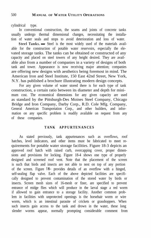
500 MANUAL OF WATER UTILITY OPERATIONS
cylindrical type.In conventional construction, the seams and joints of concrete tanks
usually undergo thermal dimensional changes, necessitating the installa-tion of water seals and stops to avoid deterioration and loss of water.
Steel Tanks.- Steel is the most widely used of the materials avail-able for the construction of potable water reservoirs, especially the ele-vated storage tanks. The tanks can be obtained or constructed of anycapacity and placed on steel towers of any height desired. They are avail-able also from a number of companies in a variety of designs of bothtank and tower. Appearance is now receiving major attention; companiesare offering new designs with aesthetics being foremost in mind. TheAmerican Iron and Steel Institute, 150 East 42nd Street, New York,N.Y. has published a brochure illustrating modern design concepts.
For any given volume of water stored there is for each type of tankconstruction, a certain ratio between its diameter and depth for mini-mum cost. The economical dimensions for any given capacity are usedas standard by the Pittsburgh-Des Moines Steel Company, ChicagoBridge and Iron Company, Darby Corp., R.D. Cole Mfg. Company,General American Transportation Corp., and other builders, and infor-mation on any specific problem is readily available on request from anyof these companies.
TANK APPURTENANCES
As stated previously, tank appurtenances such as overflows, roofhatches, level indicators, and other items must be fabricated to meet re-quirements for potable water storage facilities. Figure 18-3 depicts anapproved roof hatch with raised curb, overcapping cover, proper dimen-sions and provisions for locking. Figure 18-4 shows one type of properlydesigned and screened roof vent. Note that the placement of the screenis such that birds and insects are not able to nest on top of any portionof the screen. Figure 18- provides details of an overflow with a hinged,self-sealing flap valve. Each of the above depicted facilities are specifi-cally designed to prevent contamination of the stored water by birds orinsects. Screen mesh sizes of 16-mesh or finer, are specified to prevententrance of midge flies which will produce in the larval stage a red wormif allowed to gain entrance to a storage facility. Another common prob-lem in facilities with unprotected openings is the horsehair worm or wireworm, which is an intestinal parasite of crickets or grasshoppers. Whensuch insects gain access to the tank and drown in the water, these longslender worms appear, normally prompting considerable comment from
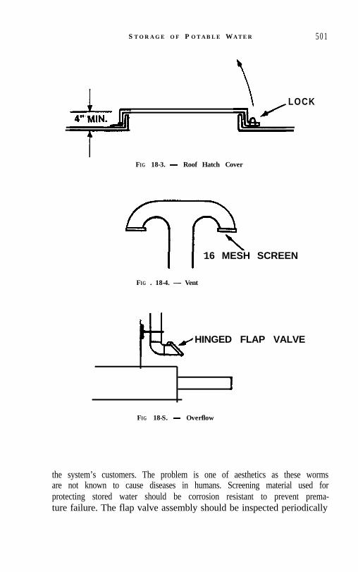
S T O R A G E O F P OTABLE WATER 5 0 1
LOCK
FIG 18-3. - Roof Hatch Cover
FIG . 18-4.
16 MESH SCREEN
Vent
HINGED FLAP VALVE
1
FIG 18-S. - Overflow
the system’s customers. The problem is one of aesthetics as these wormsare not known to cause diseases in humans. Screening material used forprotecting stored water should be corrosion resistant to prevent prema-ture failure. The flap valve assembly should be inspected periodically

502 MANUAL OF WATER UTILITY OPERATIONS
4 ” SGiiEENEP V E N T
_ ,.,.-mm . m..-.W A I Cll LCVtL
INDICATORS
3 0 ” MANHOLE
FIG . 18-7. - Water Storage Tank FIG 18-6. - Water Level Indicator

STORAGE OF POTABLE WATER 503
and lubricated to ensure that it will seal properly.Another important area of tank construction which is often modi-
fied after a tank is built is the drain outlet connection to the tank. Inheavily populated areas drain and overflow outlets are often times con-nected to storm sewer inlet facilities. When this is done, an air gap ofat least two pipe diameters must be provided to prevent contaminationof the stored water. In addition, enclosing such facilities in an inlet struc-ture obscures the view of the flap valve and hinders proper maintenanceto ensure that the flap is sealing as intended. A flap valve in plain viewand easily accessible is much more likely to be maintained properly, andprovide the necessary protection.
TANK INSPECTIONS
All tanks should be inspected annually to determine whether or notwater is being stored in a way that will not allow contamination, andto ensure that the tank itself is not suffering excessive deterioration. Suchinspections should start at ground level and should include the founda-tions and anchorage systems. For ground storage tanks, the outside shellshould be inspected for pitting, rusting, and leakage. Paint film thicknessshould be checked. For elevated tanks, the support superstructure (ped-estal, legs, etc.) should be checked as well as the ladders, overflow lines,riser pipe, and drains from ground level to the balcony. Paint film thick-nesses should again be checked on all painted surfaces.
The next step in the inspection process is to go up on top of the tankto check the top itself, as well as the roof hatch, vent and screen, overflowand flap valve (if terminated at top of tank instead of being brought downto ground level), ladders, navigational lights, if any, and any other appur-tenances which penetrate the top of the tank. As before, paint film thick-nesses are checked on representative portions of painted surfaces.
With the outside of the tank now fully covered, the inspection canmove into the tank interior. To do this, the tank must normally be drainedcompletely to be ready for inspection. On the way into the interior, theladder structure and attachment brackets should be carefully inspected,as well as the inside sidewalls, the painters ring, the roof beams, and anyinterior structural members. While in the tank, care should be taken toensure that inlet and outlet connections are operable, that the standpipe(if applicable) has a safety grate and that the standpipe itself is in usablecondition. Paint film thickness should be checked in representative loca-tions and particular attention should be paid to the areas at and justabove the normal water level (corrosion of these areas is normally accel-

504 MANUAL OF WATER UTILITY OPERATIONS
erated, inasmuch as cathodic protection where used, is effective in pre-venting corrosion only on submerged surfaces, and since this area is sub-ject to chlorine vapors and water vapor on a continuous basis. This samearea should be checked for evidence of floating scum or oil, and the bot-tom should be observed for evidence of sediment and dead spots whichwould allow development of anaerobic conditions. Evidence of any of theabove would be indicative of problems elsewhere in the system whichshould be corrected.
Although the described procedure for inspection involves drainingthe tank completely, some inspections can be made by divers in the tankswhich remain full. These inspections must, however, be made under care-fully controlled conditions to avoid problems of contamination of thestored water. Divers must be fully enclosed in a wet suit which is eithernew or which has not been used for any purpose other than diving indrinking water facilities. Diver and wet suit must be immersed in a chlo-rine solution of not less than 50 ppm for a minimum of 5 minutes priorto entering the tank. The chlorine immersion solution must be nearenough to the opening into the tank to enable the diver to be transferredto the tank without recontaminating the surfaces of the suit. Time insidethe tank must be kept to the minimum necessary to complete an inspec-tion and/or make repairs. Chlorine residual of the stored water shouldbe increased to a minimum of 5.0 ppm free chlorine. Residual levelsshould be retested after the work in the tank is completed. If the residualis less than 1.0 ppm, the tank must be disinfected in accordance withone of the methods listed in the American Water Works Associationstandards. It is not intended that major improvements of material, orremoval of deposited sludge take place by this method. If major cleaningand/or repairs are needed, the tank should be drained as described earli-er.
REPAIRS
The primary reason for frequent tank inspection on a regular basisis to detect conditions requiring minor repairs before they result in majordamage. Blind reliance on a coating system or even a sophisticated ca-thodic protection system to protect your utility’s major investment instorage is foolhardy. Adjustments must be made in either one of thesesystems (spot-treatment of pin holes on holidays or adjustment of elec-trode anchorage and current flow). In any event, proper protection foryour storage facilities requires strict attention to details when makingrepairs.

STORAGEOFPOTABLEWATER 505
Corroded areas of the tank should be sandblasted to bare metal priorto making repairs and again prior to recoating if necessary. Corrodedareas can be built up with epoxy paste or fillet welding in some instances,while more extensive repairs will require removal of the damaged plateand rewelding a replacement piece on both inside and outside seams.Welding steel plate over weakened or corroded portions of the tank isonly a stop-gap measure and may actually enhance deterioration of theoriginal plate as well as the patch.
PAINTING AND RE-PAINTING
Cull (1983) reports that tank painting for new tanks represents 10to 15% of the total cost of the tank. This represents a sizeable investmentwhich can provide an effective barrier to corrosion damage, if properlyapplied, or can fail completely in a very short time if improperly applied.A poorly applied coating can leave pinholes which actually acceleratelocalized corrosion thereby accelerating the speed at which damage tothe tank occurs. The first area which must be of concern in painting issurface preparation. Paint simply will not adhere properly to a surfacethat is coated with rust, millscale, grease, oil, or other contaminants. Forthis reason, the surface should be washed with a degreaser, and sandblas-ted to bare metal. This should be performed on new tanks as well as toremove surface films (rust, millscale, oil) which form during the produc-tion and construction stages. Standards have been established by theSteel Structure Painting Council and the National Association of Corro-sion Engineers that depict in detail what each successive stage or degreeof blast looks like. It is recommended that an area be sandblasted to thedegree specified by the contract, with the inspection and concurrenceof all parties, and that this area be coated with a clear lacquer to be usedas a reference standard for questions which may arise later. Of equalimportance to the cleanliness of the blasted metal is the blast profile ordifference between high and low points of the blast. The coatings current-ly in use vary as to their ability to cover surface roughness without allow-ing rust to form during the curing process for the first coat and the appli-cation of the second coat. The paint manufacturer should be consultedconcerning the proper blast profile for a given coat.
Coating material selection represents another critical factor in thelongevity of a tank coating. Current AWWA standards include sevenpaint systems recognized for use inside water storage tanks and fivesystems for exterior surfaces. Exterior paint systems are largely a matterof personal choice, although it has been shown that darker colors tend

506 MANUAL OF WATER UTILITY OPERATIONS
to absorb and transfer greater of heat through the tank shell, adverselyaffecting the life of the interior coating. Any color of coating with a re-flectivity rating of less than 50% should be avoided (Campbell, 1985).
Interior coating systems should be specified to meet AWWA stan-dards and individual components should have approval for use as a con-tact surface with food or food grade products by the U.S. EnvironmentalProtection Agency, United States Food and Drug Administration, orother agency or entity contracted to perform such evaluations, and au-thorized by one or the other federal agencies above.
CATHODIC PROTECTION
The interior portions of steel water storage tanks can be protectedagainst corrosion by the use of cathodic protection devices. In any situa-tion where a metal is immersed in water, the electrochemical activityof the elements involved will result to some extent in corrosion of themetal. This corrosion will cause metal ions to dissolve in the water, travelto another location in the tank and become deposited. The site fromwhich the metal dissolves is known as the anode, and this area is weak-ened and pitted as metal is removed from it. The site at which the metalis deposited is called the cathode and deposits will build up on this area.To provide protection to the tank, a network of sacrificial anodes is sus-pended in the water and an electrical current is transmitted into theanodes, through the water and onto the tank. These sacrificial anodesthen become the source of the metal moving into the solution, which prev-ents metal ions from being removed from the tank itself. This systemis reported to provide adequate protection to tanks made of uncoatedmetal. However, the use of a properly applied tank coating greatly re-duces the amount of electrical current that must be used, and thereforereduces operating costs.
Components of a cathodic protection system include anodes, whichmay be of aluminum, high silicon cast iron, platinized Niobium wire,or other metal, a rectifier circuit with a variable amperage DC output,connections between the rectifier and the anodes, an anode suspensionor anchorage system and an automatic controller. System maintenanceconsists of monthly observation and recording of the current and voltageoutputs from the rectifier to each anode string, since some areas requiremore current than others because of the amount of exposed tank surfaceto be protected, the setting of the adjustment on the rectifier, and theoptimum tank to electrolyte (water) set point on the controller. This in-formation can be collected by local personnel and any significant devia-

STORAGE OF POTABLE WATER 507
tion from recorded normal conditions should give rise to inspection andrepair of the system.
The cathodic protection system also should be inspected during theannual tank inspection to ensure that it continues to provide acceptableservice.
DISINFECTION
Potable water storage reservoirs must be disinfected after initialconstruction and painting operations, after cleaning, repairing, repain-ting, or performing any other operation which requires entrance of thetank by water utility or contractor personnel. Several methods of disin-fection with chlorine, including completely filling the tank with a chlo-rine solution, washing down the walls manually with a high strength solu-tion and then filling to. normal level and either discharging the highstrength chlorine solution to waste or allowing the chlorine level to dimin-ish and restoring the tank to service without draining are listed in theAWWA standards. These standards and their subsequent revisions areadapted as part of the Appendix A, and are used in determining adher-ence to the regulations.
Potable water storage facilities represent a sizeable portion of theinvestment of most utility systems, and they are constantly in the publiceye. Properly maintained and neat appearing facilities project a positiveimage of your utility as an efficient and properly managed concern.Hopefully, that is an image that all organizations find worth striving for.
REFERENCES
1. BORELLI, J., AND RACHFORD, T.M., “Treated Water Storage for Design CapacityReduction,” Journal of the Environmental Engineering Division, American Societyof Civil Engineers, Vol. 99, No. EE4, 1973.
2. DEB, A.K., “Optimization of Water Network Systems,” Journal of the EnvironmentalEngineering Division, American Society of Civil Engineers, Vol. 102, No. EE4, 1976.
3. Key Rate Schedule for Grading Cities and Towns of Texas with Reference to their FireDefenses and Physical Conditions, Texas Board of Insurance, Austin, Texas, 1982.
4. BEAVER, P.C., JUNG, R.C., and CUPP, E.W., Clinical Parasitology, 9th Ed., Leaand Febiger, Philadephia, Pa., pp400-401, 1984.
5. MEANS, E.G.,III, PRESTON, A.E., and McGUIRE, M.J., “Scubadiving: A Tool forManaging Water Quality.” Journal AWWA. Vol 76. No. 10. DD. 86-92. 1984.
6. ROBINSON, M.P., Jr., and BLAIR, R.E., Jr.,‘”Pump’Station ‘Design: The Benefitsof Computer Modeling,” Journal AWWA, Vol. 76, No. 7, pp. 70-77, 1984.
7. “Standard for Painting Steel Water-Storage Tanks”, AWWA D102-78.8. “Standard for Steel Welded Tanks for Water Storage”, AWWA DlOO-84.
STORAGE O F P OTABLE WATER 507
tion from recorded normal conditions should give rise to inspection andrepair of the system.
The cathodic protection system also should be inspected during theannual tank inspection to ensure that it continues to provide acceptableservice.
DISINFECTION
Potable water storage reservoirs must be disinfected after initialconstruction and painting operations, after cleaning, repairing, repain-ting, or performing any other operation which requires entrance of thetank by water utility or contractor personnel. Several methods of disin-fection with chlorine, including completely filling the tank with a chlo-rine solution, washing down the walls manually with a high strength solu-tion and then filling to’normal level and either discharging the highstrength chlorine solution to waste or allowing the chlorine level to dimin-ish and restoring the tank to service without draining are listed in theAWWA standards. These standards and their subsequent revisions areadapted as part of the Appendix A, and are used in determining adher-ence to the regulations.
Potable water storage facilities represent a sizeable portion of theinvestment of most utility systems, and they are constantly in the publiceye. Properly maintained and neat appearing facilities project a positiveimage of your utility as an efficient and properly managed concern.Hopefully, that is an image that all organizations find worth striving for.
REFERENCES
1. BORELLI, J., AND RACHFORD, T.M., “Treated Water Storage for Design CapacityReduction,” Journal of the Environmental Engineering Division, American Societyof Civil Engineers, Vol. 99, No. EE4, 1973.
2. DEB, A.K., “Optimization of Water Network Systems,” Journal of the EnvironmentalEngineering Division, American Society of Civil Engineers, Vol. 102, No. EE4.1976.
3. Key Rate Schedule for Grading Cities and Towns of Texas with Reference to their FireDefenses and Physical Conditions, Texas Board of Insurance, Austin, Texas, 1982.
4. BEAVER, P.C., JUNG, R.C., and CUPP, E.W., Clinical Parasitology, 9th Ed., Leaand Febiger, Philadephia, Pa., pp400-401, 1984.
5. MEANS, E.G.,III, PRESTON, A.E., and McGUIRE, M.J., “Scubadiving: A Tool forManaging Water Quality,” Journal AWWA, Vol 76, No. 10, pp. 86-92, 1984.
6. ROBINSON, M.P., Jr., and BLAIR, R.E., Jr., “Pump Station Design: The Benefitsof Computer Modeling,” Journal AWWA, Vol. 76, No. 7, pp. 70-77, 1984.
7. “Standard for Painting Steel Water-Storage Tanks”, AWWA Dl02-78.8. “Standard for Steel Welded Tanks for Water Storage”, AWWA DlOO-84.

CHAPTER 19
CUSTOMER METERS
FRANK DANNENBAUM
Rockwell In terna tional Corpora tion
The use of water meters today is accepted by water utilities as the most equitable manner to distribute the cost of operating a water system. It also is one of the best tools at the disposal of the water utility for the conservation of existing supplies. If the cost of a meter installation can be jusrified in the first place, it follows that the cost of keeping this meter in a reasonably accurate condition thereafter also can be justified. Met- ers should not be placed in service and forgotten until they fail to func- tion. Some routine repair program should be established, based upon the water, its cost, soil, and other conditions peculiar to that particular sys- tem.
TYPES OF METERS
Positive Displacement Meter. - The positive displacement meter is a meter containing a measuring chamber with a fitted disc or piston. As this chamber "fills" and "empties" one time, the disc or piston makes one cycle, thereby measuring the volume of water of the chamber assem- bly by physically and positively displacing it. By use of gears, these cycles are counted and transferred to the meter register either in gallons or oth- er desired units of measure.
In the past, there have been several types of positive displacement meters, but today there are only two manufactured in the United States for ordinary utility service. These are the oscillating (piston) and the nu- tating (disc). They both operate on exactly the same principle, except for the motion of the piston.
For many years the positive displacement meter contained an open or oil-enclosed gear train, stuffing box and standard round or straight reading register. The objection to this meter was that in time the stuffing box would wear, and then leak. Condensation would collect under the glass, making it difficult to read and in time, dirt and moisture would enter the register itself.

TABLE 19-1. - Nominal Capacity Ratings and Related Pressure Loss Limits for Cold- Water Displacement Meters - AWWA Standard C700
Meter Sizc in.
We' Maumum Operating c4-1~
RP"'
See Scc. AS. 1. AWW A SUnQrd C700 t See Scc. 18-Regstmtion Accuracy. AWWA Standard 0 0 0 Note: Table is quad with p r m i s s ~ o n fmm "AWWA Standard for Cold-Water Mcters-
IhsplrcemenI Type." AWWA #a) copyrighted by the American Water Wwks Assocml~on.
Max~mum P m u m
Loss at M e b u m u r n Opmtng G p a t y
pri
I3 13 13
Today, all American meter companies manufacture a magnetically driven meter with a sealed register. A permanent magnet is driven by a disc or piston spindle inside the water compartment. A receiving mag- net is located in a separate compartment with the reduction gears and register. Each revolution of the disc or piston spindle enables the driven magnet to revolve. The receiving magnet turns the same number of rev- olutions and transfers this information through a series of gears to the register itself and records in gallons or cubic feet. The use of magnets to transmit the information from the measuring chamber to an externally sealed compartment eliminates the stuffing box and stuffing box leaks. It enables all the gears and register to be contained in a dirt and moisture- proof container. These sealed register meters come in two types, those that are permanently sealed by the manufacturer and those that can be disassembled and repaired in the local meter repair shops. Characteris- tics of displacement meters are shown in Table 19-1.
Current Meters. - The current or velocity type meters are of two types - turbine type for customer service in which water flowing through it operates a bladed wheel and a propeller type for main line applications. In the turbine type, the turbine is placed in a removable cage. The propeller or wheel in the propeller meter is not so arranged and operates in the line or meter body. As the velocity of the water in- creases, the speed of the wheel increases and this information is calibrat- ed in gallons or cubic feet. Current meters have a relatively low loss of head but are not considered suitable for use on a domestic service where
Recan- mndcd*
Maurnurn RAW of
Cont~nuous O p m t ~ o n s
gP"J
10 15 25
M~nrmum Test Flowt
gpm
% M %
Norm81 Test Flow
Lrmtst gPm
Maumum Number of DISC N u ~ t m s Or P~ston Orctlhtlons
per 10 gal per cu fr
435 250 l 15
1- 20 2- 30 3- 50
580 333 153

TABLE 19-2a. - Nominal Capacity Ratings and Related Pressure Loss Limits for Cold- Water Meters - Turbine Type for Customer Service AWWA Standard . .
C701 Class I
CLASS I k l n Line (High Vdocity Type)
all rates of flow will be encountered. This meter is not accurate on low flows. These meters are used generally as the large size of compound meters. Table 19-2a and 19-2b list characteristics of current meters.
Improvements in turbine type meters have been made relative to design, accura cy and loss of hea d. For in for ma tion-concerning these met - ers and their improved characteristics, refer to the latest revision of A W WA C- 701, Standard for Turbine Type Meters (2).
Another type of velocity meter introduced into this country is the multi-jet meter. These meters are manufactured in sizes %-in and larger and for the most part are either imported, or manufactured under foreign patents. The ability to pass sand or other foreign substances is normally considered better than the displacement type meter of the same size; however, they have the disadvantages of other velocity type meters. That is, their accuracy will be affected by pulsating flow, chemical build up on the wheels or cages, and any decrease in the size of the openings or orifices that direct water to the bladed wheel will cause the meter to be- come fast to a degree beyond that of the displacement type meter.

TABLE 19-2b. - Nominal Capacity Ratings and Related Pressure Loss Limits for Cold- Water Meters - Propeller Type for Main Line Applications, AWWA Standard C704
Meter Size, in.
Safe Maximum Operating Capacity,
k'pm
Maxmum Rate for Continuous
Duty, RP"
Maximum Loss of Head at Safe
Maximum Operating
Capacity -psi
Normal Test Flow Limits,
gpm
Minimum Test Flow
RPm
Note: Tables 2a and 2b are quoted with permission from AWWA Standards AWWA C701 and AWWA C704 respectively, copyrighted by the American Water Works Association.
The AWWA has issued C-708-82 (8), Standard for Cold-Water Meters, Multi-Jet Type for Customer Service.
Compound Meters. - The compound meter uses two meters housed in the same case with an automatic valve. Usually a displacement type meter is used to measure the low flow, and the current type is used to measure the high flow. It is so designed that when the demand exceeds the capacity of the displacement meter a valve will automatically open, allowing the current meter to begin operation. At this point where the automatic valve begins to open, the initial water entering the current wheel may not be enough to operate it accurately. This is usually of a very short range and is provided for in the A.W.W.A. Specifications (4) for compound meters. Characteristics of compound meters are given in Table 19-3.
Fire Service Meters. - One type of fire service meter is a combina- tion of two or more meters and differs from the compound meter in that the main line side is a proportional meter. A proportional meter, as the name implies is a meter where only a portion of the water is diverted through a meter. The remainder of the water passes through without

TABLE 19-3. - Nominal Capacity Ratings and Related Pressure Loss Limits for Cold- Water Meters - Compound Type, AWWA Standard C702
3 . . . . . . . . . . . . . . . . . . . . . . . . . . . . . . . . . . . . . . . . 20 gpm 4 . . . . . . . . . . . . . . . . . . . . . . . . . . . . . . . . . . . . . . . . 30 gpm 6 . . . . . . . . . . . . . . . . . . . . . . . . . . . . . . . . . . . . . . . . 40 gpm 8 . . . . . . . . . . . . . . . . . . . . . . . . . . . . . . . . . . . . . . . . 75 gpm
10 . . . . . . . . . . . . . . . . . . . . . . . . . . . . . . . . . . . . . . . . 100gpm Note: Table '
3 is quoted by permission from AWWA Standard C702 The footnote is adapted from Sec. 19 of the same standard.
Meter Slze,
in
2 3 4 6 8
10
contacting any measuring device. The meter which measures a portion of the water is so calibrated to include not only the water that it actually measures, but it also infers the entire amount passing through the meter. The measuring device may be either the displacement type or the velocity type. This type of meter will not measure low to intermediate flows. I t is usually used on fire lines where a low loss of head is desirable, and normally in conjunction with an automatic valve, which allows the small meter to measure the low flows. The accuracy of this meter is highly influenced by the piping arrangement on the inlet side of the meter. In- stallation instructions from the manufacturer should be closely followed. This meter is not currently covered by an AWWA standard.
* Registration: See Sections 15 and 19 AWWA Standard C702 At normal test flow, rates shall be not less than 97% nor more than 103% of water actually passed through the meter, except in the registration of flows within the "change- over" from by-pass meter to main meter. The registration at these rates of flow shall be not less than 85%. The difference in the rate of flow at the beginning and end of the "change-over" shall not exceed the figures given in the following table:
. . . . . . . . . . . . . . . . . . . . . . . . . . . . . . . . . . . . . . . . 2 20 gpm
Safe M a x ~ m u m Opera t~ng Capac~ty , KPm
160 320 500
1 ,ooo 1,600 2,300
In addition to the fire service meter previously described, there is a device commonly known as the "detector check" used on private firel- ines. This is not a meter in the true sense, but is a monitor to ascertain the unauthorized movement of water into a private fire service. I t consists
Maxlmum Rate for Contmuous
Duty, RP'n
80 160 250 5 0 0 800
1,150
Maximum Allow- able Loss of Head at Safe
Maximum Operating
Capacity, prr
20 20 20 20 20 20
Normal Test Flow Lirn1t5 *
XPm
2- 160 4- 320 6- 500
10- 1,000 16- 1,600 32-2,300
Mtnlrnum Test Flows,
?P'"
?4 !A 34
1 % 2 4

of a check valve comparable in size to the size of the fireline, plus a small disc meter located beside the check valve with its inlet above the check
TABLE 19-4. - Nominal Capacity Ratings and Related Pressure Loss Limits of Fire Ser- vice Meters - Adapted from AWWA Standards C703
Maximum Loss of Head
psi Meter S m
I I l ~ 11
3 4 6 8
10 12
Minimum Test Flow
g p n 7
Safe Maximum Operating Capacity
A1!) /I l
400 700
1,600 2,800 4,400 6,400
Normal Test Ftow
L l m ~ t s gp1rr
Registration: Minimum test flow: not less than 95%. Normal test flow: not less than 97% to 103%. Change-over: Not less than 85%.
valve and its outlet below. All water is measured by this small meter until the flow becomes great enough to open the check valve. Usually a 3 1/ 2 to 4 psi drop in pressure across the valve will open this valve. The water that flows through the open check is not metered, but any consumption on the small meter above that necessary for testing purposes, should war- rant an inspection for illegal usage or wastage.
ACCURACY
In purchasing new meters and in repairing old ones, a judgment should be made of their accuracy before installation. The publication of the American Water Works Association, entitled, "Water Meters - Selection, Installation, Testing and Maintenance" and designated AWWA No. M6, Third Edition (1986) (9), is a dependable guide. With respect to accuracy of new and old meters, the following is adapted from that publication copyrighted by the American Water Works Association with their permission:
Meters have an inherent variation of 2-3 percent in registration over the entire range of flows, except very low flows just above those that the meter will not register. As an example, a 78 in. water meter in good condi- tion will register within the following limits: 95 percent or higher at 1/ 4-gpm flow, rise to a maximum of 101.5 percent at 2 gpm (usually 10 percent of rated meter capacity), and then falling off on a flat curve to

I I I I I I v!""""" 8 8 g % ( g % 1
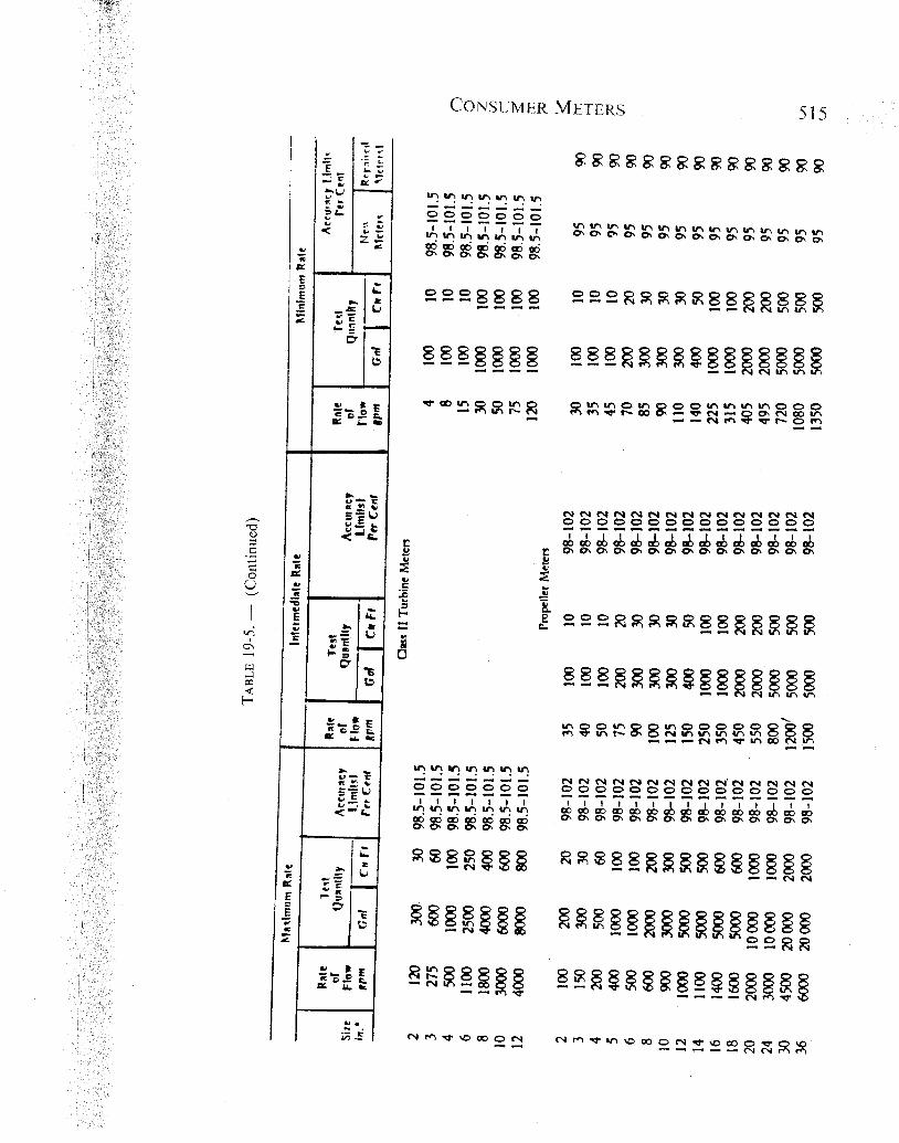

not less than 98.5 percent at 20 gpm, which is the rated meter capacity for a %-in meter
It is not considered feasible to repair older meters to pass the accura- cy requirements for new meters on the minimum rate. For this reason, separate accuracy limits are shown in Table 19-5 for new and repaired meters on the minimum flow test. The limits for repaired meters are con- sidered to represent those that require good meter shop procedures to achieve. It is not considered that acceptable meter repair work is being accomplished if repaired meters will not register at least 90 percent on this test. A higher percentage is recommended for desirable shop quality standards.
SELECTION OF METERS
Selection of Type of Meter. - On the average domestic water ser- vice requiring various rates of flow, the displacement type meter is usual- ly used up to 2" in size. On most services larger than 2" in size, where various rates of flow are encountered, compound meters are usually se- lected. Occasionally, where withdrawals are limited to uniform moderate to high rates of flow, a current meter will suffice. In most cases where water for fire protection is required inside the property, such as fire hydrants or sprinkling systems, a fire service meter is desirable.
Selection of Size of Meter. - Determining the proper size of meter for a particular service can be a difficult task. In most cases, the maxi- mum amount of water provided by the various sizes of services and met- ers can be used by the experienced operator to determine a proper size. It is not uncommon for services to be over-metered where preliminary service studies have not been made. Frequently an architect will suggest a meter and service size inconsistent with the actual water requirements. Rather than take a chance on the service being too small, he will usually recommend an over-size meter. Lower pressure conditions at various places in the distribution system might necessitate a larger service and meter than would be required in other parts of the system having higher pressure. These factors, along with knowing some peak demands of a particular consumer, will be most helpful in selecting the proper size. The number and type of water outlets is also an important factor in deter- mining the proper size along with the length of services from the main to the customer. The "Meter Manual," (9) AWWA No. M6, Third Edi- tion, (1986) and "Sizing Water Service Lines and Meters," AWWA No. M22 (1975), provide tabular data on the various factors involved and sample calculations.

REPAIRS
The repair shop, whether servicing a large utility with assembly line procedures or a one man shop, does essentially the same job. A water meter should be in-tested in some cases; dismantled, cleaned, reassem- bled with proper repair, and tested. These functions should be performed regardless of the size of the shop. The following procedures should be followed in the repair of displacement type meters.
Dismantling. - A meter removed from service should first be "hosed down" to dislodge the easily removed dirt that might be attached to the outer case. It should then be dismantled. This function does not require a lot of experience with meters, but should be done with the ut- most care. Steel hammers should never be used in separating the meter cases or various meter components. Instead, rawhide mallets or plastic hammers should be used which will not distort the component parts. It is generally agreed that it is advisable to keep the various meter parts together as a unit so that they might be reassembled as the same unit. This is not necessarily true of the meter register and intermediate gear train, which is a self-contained unit.
Cleaning. - There are various types and methods of cleaning water meters and their component parts. Perhaps the most common procedure is the use of commercial cleaners. Most of these commercial cleaners contain muriatic acid with an inhibitor. These inhibited acids are much safer to use and do not damage the meter parts. Some of the electronic companies have developed ultrasonic cleaners which are used successful- ly by some meter repair shops. This is accomplished by the use of diluted inhibited acids, along with the sound waves from the ultrasonic machine. There are several types of vapor blast machines on the market which use various kinds of abrasives. Most of these abrasives are gentle enough to clean the meter adequately without harm to the most delicate parts.
Reassembly. - The assembly of the meter is essentially the assem- bly of its component parts. The repair of the register is primarily a thor- ough inspection and replacement of worn gears, bushings and faded dial plates. Many shops prefer to reset the register to a zero reading although magnetic drive meters are not normally reset to zero. The repair of the intermediate gear train includes an inspection of the individual gears, pinions, bushings and shafts. Those worn beyond reuse should be re- placed. Adequate lubrication should be provided for the gear train. The heart of the meter is the measuring chamber. To do an adequate job of repairing a measuring chamber requires more skill than perhaps any oth- er part of the meter. In case of the nutating type, the chamber itself
should be cleaned thoroughly and the disc pistons should be carefully examined. The fit of the disc in the measuring chamber is very critical. In some cases it is necessary to use over-size balls to insure a proper fit in case the sockets of the chamber are worn. In other types of nutating chambers, it might be necessary to rotate the bottom plate or possibly replace this plate in order to get the proper fit.
In case of the oscillating type measuring chamber, the repair will consist of the careful inspection of the chamber interior and the removal of any scratches or burrs that may interfere with the piston movement. The piston should be examined carefully and all burrs and scratches re- moved. The rollers should be inspected carefully for wear and replaced if necessary. In the repair of all measuring chambers, whether nutating or oscillating, the sense of "feel" plays an important part. Only experi- ence can provide the repairman with this essential element.
In the reassembly of the meter, all gaskets should be replaced and stuffing box packing renewed. The assembler should use precautions to see that the proper alignment is made between the gear train measuring chamber and register as they are reassembled. An experienced assembler will blow gently through an assembled meter to detect any misalignments which might have occurred before it is tested for final approval.
Testing. - The testing, as explained here, pertains to the displace- ment type meter. The purpose of testing a reassembled meter is to deter- mine whether it will perform with the degree of accuracy expected. If there have been any mistakes in the repair and assembly, it will be disclo- sed here and should be corrected. The testing of meters before they are repaired is a good way to evaluate the over-all efficiency of meters in service. Before a routine repair program is instituted, the test of meters that have been out various lengths of time will be of invaluable help in determining the proper time element for a meter program.
The most common type of shop testing of small meters is the use of the volumetric tank which is used in conjunction with most test benches. The tank is reasonably inexpensive and permits the testing of a number of meters a t one time. The tanks are calibrated accurately and equipped with a small diameter gauge glass with an adjustable measure- ment scale for accurate reading. All test tanks should be checked periodi- cally for accurate calibration. For the average shop, two tanks should be provided. Gravimetric (weigh) tanks provide compatible or better ac- curacy if the scales are properly maintained. The tanks should have ca- pacities of ten and one hundred gallons, or one and ten cubic feet as the case might require. These tanks are large enough to provide adequate capacity for one complete revolution of the test hands on all meters up

I WORK TABLE I SHELVES UNDER,
I DISASSEMBLY BENCH
FIG . 19-1. - Diagrammatic Plan of a Disassembly and Cleaning Room. No Scale
to 2" in size. Various rates of flow and various quantities of water have been es-
tablished by A.W.W.A. for various types and sizes of meters in the tes-
LWORK TABLES
I
FIG . 19-2. - Diagrammatic Plan of a Well-Arranged Repair Shop. No Scale

ting of cold water meters (see Table 19-5). Rate of Flow Control. - It is important that meters be tested at
known and controlled rates of flow, rather than by testing through an orifice which will vary greatly under various pressures. There is a device available for the testing of water meters that will give the rate of flow from 1 /4 gpm upward, This device remains reasonably accurate in deter-

mining the rate of flow, regardless of the number of meters tested, or the variation in pressures that might occur. This device is provided on many test benches.
Five-eights inch meters should be tested with at least three rates of flow: a minimum rate of 114 gpm, an intermediate rate of 2 gpm and
a maximum rate of from 15 to 20 gpm. The exact rate of flow at the maximum rate is not so important but the minimum and intermediate rate should be adhered to closely. Rates of flow to be used in the testing of other sizes and types of meters are shown in the figures.
Because of the variations in waters, water costs, scarcity of water and meter repair costs, the degree of accuracy required of a repaired meter will vary in different locations. With water becoming more scarce in many places, and more costly in virtually all places, it may be well to increase accuracy desired. The American Water Works Association specifications require a new %" meter to register no less accuracy than 95 percent and no more than 101.0 percent on the minimum flow rate of 114 gpm, and shall register with 98.5 percent to 101.5 percent on the normal rates of flow from 1 gpm to 20 gpm. Many utilities today require their %" repaired meters to meet these standards except the minimum rate of flow accuracy is lowered to 90 percent.
In many cases it is desirable to test a meter for accuracy because of a consumer's complaint of a high bill. In such cases, it is desirable to have the consumer witness the test in person. This is not always possi- ble, however, and in such cases some routine understandable analysis of the test should be sent to the customer. The characteristics of the dis- placement type meter are such that it is almost impossible for it to be fast. The meter can be over-read or under-read, meter hands on the round reading type can be knocked from one position to another. In such cases, the billing will be in error. A careful examination of all register hands, register gears and change gear combinations should be made on all con- sumer complaint meters. Many water utilities will test a meter removed for a consGmer complaint at four or five different rates of flow. The re- sults of the over-all accuracy are then mailed to the consumer. I t is rare indeed that adjustments are necessary because of a fast meter, but this service is helpful in maintaining good customer relations. Some suppliers provide small portable testers specifically for this purpose.
Many of the larger water utilities have facilities for testing current, compound and fire service meters in their shops. Such equipment is ex- pensive and is not financially feasible for the smaller shops. This equip- ment usually consists of tanks holding in excess of one thousand gallons and rates of flow devices. These meters are tested in a similar manner to the smaller meters; however, in the testing of compound and fire ser- vice meters, specific rates of flow should be selected that will determine the accuracy of all meters contained in the compound or fire line meters being tested. In the repair of compound and fire line meters, the repair

of the automatic valves is equally as important as the repair of the meters themselves.
FIELD INSTALLATION AND TESTING
It is desirable to test and repair 2" and larger compound fire line meters in the field. Before this can be done, an adequate installation is essential: ample working space, valves on both inlet and outlet side of the meter, sufficient drainage for discharged test water. Either perma- nent or temporary bypasses around the meters are preferable, in order to make the test and repair without discontinuing water service to the consumer, which otherwise would mean night or weekend work. The per- formance of fire service meters is influenced by the piping arrangements on the inlet side of the meter. Hence, it is better to get a test on the meter in place, rather than in the shop. It is recommended that the meter be set in a level position, with a minimum of eight diameters of straight pipe the same size as the meter, installed on the inlet side of the meter. Most larger cities have standard installation specifications for large size meters.
Field test equipment usually includes a small displacement type me- ter (%" to 1") to test the low flows and a 3" or larger current type meter to make the higher test. I t is preferable to have test equipment in the shop that can handle these test meters, in order that they will stay a t their maximum accuracy at all times. It is desirable to have orifice plates of various sizes, which can be installed on the outlet side of the test met- ers, in order to have a consistent variation of flow. It is also desirable to use a stop watch in conjunction with these orifices, in order to establish the exact rate of flow. Of course these orifices will pass different amounts of water in various parts of the distribution system, because of the vari- able pressures involved. In cases where the velocity type meter is used for test purposes on large flows, it may be advisable to have an exact accuracy curve computed with shop testing equipment. When this meter is used for field testing, the meter being tested can be corrected to the curve of the test meter. Normally, the test meter can be calibrated close enough to 100 percent accuracy and the curve is flat enough to make this procedure unnecessary. It is desirable, when conditions permit, to in-test all large meters for repair, as well as to test them after repair. In this way you can properly evaluate the work being done. Again, most suppliers are providing prepackaged large meter testers that will facili- tate field testing of a11 large meters.

LENGTH OF SERVICE
Long before a meter will actually stop registering from wearing out it will get slow, particularly on low flows. We are not referring to the meter that has stopped because of sand, pipe scale, ice or hot water. These are all natural enemies of any cold water meter and will stop a new meter. Rather, we are referring to the meter that is allowed to stay in service year after year, and because it has a larger reading this month than it did last month, it is allowed to remain in service. This meter, like any other instrument with moving parts, will wear gradually. The gradual decrease in accuracy over a few months is so small that it will not be noted by the meter readings. However, over a period of many years (and some meters have been left in service for over 25 years without attention), the degree of slowness will be substantial.
Various time and consumption factors have been proposed as crite- ria for the removal from service and routine repair of water meters. No definite time can be established which will pertain to all meters in all systems. This is because of quite a variation of the different meters, soil conditions and water quality. When a meter stays in service long enough for decreased revenue to pay for the replacement or repair, it is common sense to remove it. In addition, each water utility has a moral obligation to treat all customers the same. Each operator should determine for him- self at what years of registration the meters should be removed for rou- tine replacement or repair. The information gathered by in-testing met- ers that have been out for differing numbers of years, with various amounts of registration, will be helpful in determining a repair cycle.
Table 19-6 gives suggestions on the frequency of testing. However, many state regulatory commissions have adopted regulations on the sub- ject, and these are listed in the AWWA Meter Manual No. M6, Third Edition (1986) (9). In places where meter records are not available, these will be valuable in establishing a routine repair program.
RECORDS
The keeping of adequate meter records is not a big undertaking. In larger utilities automatic equipment keeps them. The small or average size shop can keep adequate meter records on a card system. The infor- mation to be compiled on this card should identify the size, make, model and number of the meter, location of the meter setting, date of the meter setting and identification of the individual doing the work. When this meter is removed from its location, it should be noted on the card with

Meter Size Inch
CONSUMER METERS
TABLE 19-6. - Years Between Tests
Displacement Meters
Compound Meters
Current Fire Service Meters Meters
the reading and date of its removal. Parts and labor used in the repair should be shown. This information can also be recorded on prenumbered work sheets. These sheets should show the various parts used and labor involved in the repair. In turn, this work sheet number could be recorded on the card for easy referral. Various colored plastic tabs can be used to represent a particular calendar year, and to indicate time in cycle for repair.
Field Repair and Test Record. - Field records also are important. All types of repairs and tests on meters in the field should be recorded and filed for quick reference. The records should include the nature of repair and meter data, including the change gear data if the meter is so equipped.
CARE AND PROTECTION OF' METERS
Water meters are the cash registers for the water works. The people handling meters in the repair shop or in the field should be trained to handle and protect them properly. Regardless of make, size, type, new or used, meters should be handled with proper care. Failure to care for meters properly could result in unnecessary loss of revenue and costly repairs. All meters should be protected from the sunlight, especially in hot weather. The pistons, bushings, and other internal components are made of hard rubber and synthetic polymers which will expand or de- grade when subjected to heat or sunlight, possibly sticking the meter or warping the internal parts causing the meter to register slow. Also, ex-
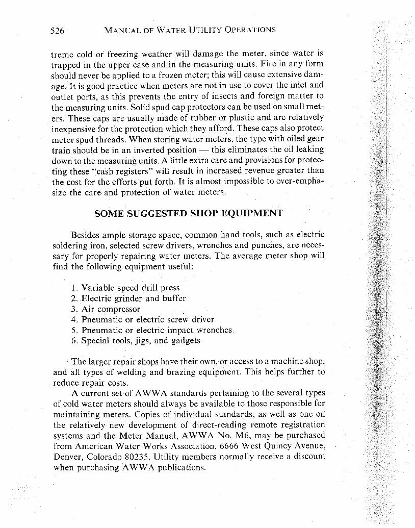
treme cold or freezing weather will damage the meter, since water is trapped in the upper case and in the measuring units. Fire in any form should never be applied to a frozen meter; this will cause extensive dam- age. It is good practice when meters are not in use to cover the inlet and outlet ports, as this prevents the entry of insects and foreign matter to the measuring units. Solid spud cap protectors can be used on small met- ers. These caps are usually made of rubber or plastic and are relatively inexpensive for the protection which they afford. These caps also protect meter spud threads. When storing water meters, the type with oiled gear train should be in an inverted position - this eliminates the oil leaking down to the measuring units. A little extra care and provisions for protec- ting these "cash registers" will result in increased revenue greater than the cost for the efforts put forth. It is almost impossible to over-empha- size the care and protection of water meters.
SOME SUGGESTED SHOP EQUIPMENT
Besides ample storage space, common hand tools, such as electric soldering iron, selected screw drivers, wrenches and punches, are neces- sary for properly repairing water meters. The average meter shop will find the following equipment useful:
1. Variable speed drill press 2. Electric grinder and buffer 3. Air compressor 4. Pneumatic or electric screw driver 5. Pneumatic or electric impact wrenches 6. Special tools, jigs, and gadgets
The larger repair shops have their own, or access to a machine shop, and all types of welding and brazing equipment. This helps further to reduce repair costs.
A current set of AWWA standards pertaining to the several types of cold water meters should always be available to those responsible for maintaining meters. Copies of individual standards, as well as one on the relatively new development of direct-reading remote registration systems and the Meter Manual, AWWA No. M6, may be purchased from American Water Works Association, 6666 West Quincy Avenue, Denver, Colorado 80235. Utility members normally receive a discount when purchasing AWWA publications.

REFERENCES
The latest revision of each of these standards should be used.
1. AWWA C700- (Displacement Type). 2. AWWA C701- (Turbine Type for Customer Service). 3. AWWA C704- (Propeller Type for Main Line Applications). 4. AWWA C702- (Compound Type). 5 . AWWA C703- (Fire Service Type). 6. AWWA C706- (Direct-Reading Remote Registration Systems). 7. AWWA C707- (Encoder-Type Rework Registration Systems). 8. AWWA C708- (Multi-Jet Type). 9. "Water Meters - Selection, Installation, Testing and Maintenance," AWWA No.
M6, Third Edition (1986). 10. AWWA M22. "Sizing Water Service Lines and Meters."

CHAPTER 21
ENERGY CONSERVATION IN PUBLIC WATERSYSTEMS
T. ANTHONY REID, P.E.
Freese and Nichols, Inc., Consulting EngineersArlington, Texas
The cost for energy has assumed an increasing percentage of a pub-lic water system’s operating expense in recent years, and it will likelyincrease in the foreseeable future. Although always important, currenttrends require greater consideration of energy consumption in a watersystem’s operation.
Conservation studies on how energy could be saved in the operationof a water system suggest that there are a series of logical actions thatshould be followed to accomplish this objective in any water utility. Thesesteps are:
1. Determine the quantity of energy being consumed in the opera-tion of the water system and at what cost.
2. Determine how or where the energy is being consumed.3. Evaluate the physical characteristics of the water system equip-
ment that have the most significant impact on the energy requirements.4. Evaluate the operational procedures that involve this equipment
with particular emphasis on establishing how efficiently the equipmentis being used.
5. Establish revised operational procedures that are designed tomake the most efficient use of the water system equipment.
The determination of the quantity of energy consumed in the opera-tion of the water system and at what cost can normally be made froma review of the previous utility bills. A typical annual distribution of theelectrical consumption and demand are illustrated in Figure 2 l- 1. Slight-ly more than one-half of the total consumption occurs during the period,June through October. This emphasizes the importance of efficient oper-ation in both the high and low demand periods.
How or where the energy consumption is occurring can be answeredby a detailed energy audit of the facilities. An energy audit is simplya tabulation of all items that use some form of energy with a listing oftheir significant energy consuming characteristics. Where electrical
544
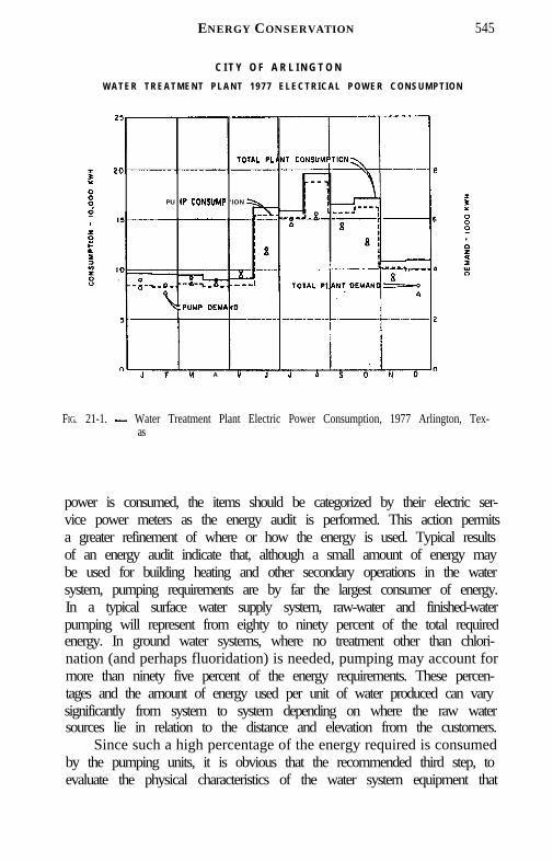
ENERGY CONSERVATION 545
C I T Y O F A R L I N G T O NW A T E R T R E A T M E N T P L A N T 1 9 7 7 E L E C T R I C A L P O W E R C O N S U M P T I O N
PU 1P CONSUMP ‘ION
M A M
FIG. 21-1. - Water Treatment Plant Electric Power Consumption, 1977 Arlington, Tex-as
power is consumed, the items should be categorized by their electric ser-vice power meters as the energy audit is performed. This action permitsa greater refinement of where or how the energy is used. Typical resultsof an energy audit indicate that, although a small amount of energy maybe used for building heating and other secondary operations in the watersystem, pumping requirements are by far the largest consumer of energy.In a typical surface water supply system, raw-water and finished-waterpumping will represent from eighty to ninety percent of the total requiredenergy. In ground water systems, where no treatment other than chlori-nation (and perhaps fluoridation) is needed, pumping may account formore than ninety five percent of the energy requirements. These percen-tages and the amount of energy used per unit of water produced can varysignificantly from system to system depending on where the raw watersources lie in relation to the distance and elevation from the customers.
Since such a high percentage of the energy required is consumedby the pumping units, it is obvious that the recommended third step, toevaluate the physical characteristics of the water system equipment that
546 MANUAL OF WATER UTILITY OPERATIONS
have the most significant impact of the energy requirements, should beprimarily towards the pumps. Although pump manufacturers often pro-vide curves that describe the head-discharge-efficiency characteristicsof a pump, the pumps characteristics normally change with wear. Theactual application operating conditions may not correspond to the as-sumed design conditions. Pumps should be tested in the field to determinewhether the present head-discharge relationships remain in generalagreement with the original manufacturer’s curves when operating un-der actual field conditions.
Tests performed in the field are rarely as accurate as those that canbe obtained under controlled laboratory conditions. A method of testinghas to be devised which permits the measurement of the operating head,the rate of flow, and the amount of power consumption with a reasonabledegree of accuracy. The discharge pressure can be effectively measuredwith a pressure gauge mounted on the discharge piping of each pump.The suction elevation can be determined from measurements of the watersurface level in a clearwell or in a lake. The operating head can be variedby manipulation of a valve downstream from the pump or by operatingother pumps which discharge into the same header. The use of valvesto adjust the head should be carefully considered. Valves, particularlya gate valve, can be damaged if the velocity through the valve becomestoo great. It is important to vary the head over as wide a range as possiblein order to obtain a reliable comparison with the original manufacturer’shead-discharge-efficiency curves. See Chapter 14.
The flow rate can be determined by measuring the level change ina clearwell of known dimensions over a carefully noted time span duringwhich the pump is operated against a reasonably constant discharge pres-sure. It is important to insure that no water enters the clearwell duringthe test or leaves by any other means than the test pump. The elapsedtime of the test should be sufficient to minimize the effect of any errorin the determination of the change in volume. A stop watch can be usedto insure accuracy in measuring the elapsed time to within a very fewseconds. The clearwell level can be measured with a weighted steel tapenormally to a precision of one quarter of an inch. Determining the flowrate with the change in the volume for a known period of time is recom-mended, but flow meters can be used if that is the only method readilyavailable. The calibration of the meter should be carefully determinedbefore the test and checked after the test is completed. The results witha flow meter will probably not be as reliable as those obtained from avolume change test because of the accuracy of the meter and the abilityto read the indicated flow.

ENERGY CONSERVATION 547
A vital part of any water system energy conservation study is thedetermination of each pump’s unit energy consumption in kilowatt hoursper gallon. To do this, the power drawn by a pump motor must be mea-sured or calculated accurately over the normal operating range of flowsand pressures of the pump.
The electrical power consumed during the test can be measured us-ing the standard power meter already installed by the electric servicecompany. The rotating disc in the meter moves at a speed that is propor-tional to the power demand. The time required for the disc to completean appropriate number of revolutions, usually five to ten, can be mea-sured. Many power meters have a specific constant, or a multiplier (oftenshown on the meter nameplate) which must be used to determine thetotal power used. The specific constant is frequently expressed as onethousand times its actual value. The local power company should be ableto confirm the proper factor. An inventory of the energy consumingequipment whose usages are recorded by the meter should be made priorto the test to insure that the meter readings reflect only the power de-mand of the pump’s electrical motor.
.With the determination of the power meter’s characteristics and itsoperation during the test, the actual electric power demand, expressedas horsepower, can be determined from the following equation:
Eleatritz Demand <HP) = Sprcific Constant X No. of Rsv x 36001000 X Elrprrd time(reo) X 0.746 KW/HP
The overall efficiency is the ratio of the energy delivered by thepump to the energy supplied to the input side of the driver. For example,the overall efficiency of a motor driven pump is the ratio of the liquidhorsepower to the electric horsepower. This method of testing pumps isfairly inexpensive and requires no special equipment, yet the results ob-tained can give a valuable indication of each pump’s performance.
The results of field tests of the head-discharge-energy relationshipfor a specific pump using this method are illustrated in Figure 21-2. Thisillustrates the information that can be obtained from tests of this type.The pump was one of the oldest and smallest in use in the water system.The three test points which lie below and to the right of the head dis-charge curve indicate that the modern-day system head levels are notsufficiently high to allow the pump to operate in its design range. Asit is commonly stated, the pump is running off the end of its curve. The

548 MANUAL OF WATER UTILITY OPERATIONS
WHEELER ECONOMY HORIZONTALCENTRIFUGAL PUMP
10x8 TYPE M PUMP 17SORPMP U M P SEftlAl. NUMBER AS- 22499-2
DISCHARGC IN IO00 OILLOW PER MINUTE
FIG . 21-2. - Pump No. 1, Wheeler Economy Horizontal Centrifugal Pump 10 x 8 TypeM, 1750 RPM Ser. # AS-22498-2
fact that the data points fall below the manufacturer’s head-dischargecurve is a further indication that the pump is worn and the pump is appar-ently no longer providing the anticipated design flows.
The heads that a pump are required to operate against are otherfactors that should not be overlooked. High-service pumps are a combi-nation of the static lift from the water surface in the clearwell to the watersurface in an elevated storage tank and the frictional head losses whichresult from the flowing of the water through the water system’s pipelinenetwork. The loss of head that results from water flowing through a cer-tain pipeline can be expressed as:
The C in the equation is an expression of the internal “conveyance capa-bility” of the pipeline and is commonly referred to as the “C-Factor”.
The electrical power required to pump the water through the pipeat a certain rate can be expressed as:
ENERGY CONSERVATION 549
The power required to pump a certain rate is directly related to the inter-nal condition of the pipeline.
The conveyance capability (C-Factor) of a new pipe properly in-stalled is normally around 140. As the pipe is used through the years,the conveyance capability decreases. The rate of decline is dependenton many factors. Some of the more important are the pipe material, wa-ter quality and velocity. An appropriate relationship for the rate of de-cline of the conveyance capability with time can be determined from fieldtests on selected pipelines in the water system. The conveyance capabilityof installed pipelines can be determined in the field by measuring thehead loss between two selected points that are a known distance apartand by determining the average velocity in the pipe during the test. Atypical conveyance capability-time relationship is illustrated in Figure21-3. Starting with a C-Factor of 140, the conveyance capability declineson the average to approximately 94 after ten years. C-Factors much be-low this level are not desirable in the principal pipeline network.
Primary distribution pipelines are often designed to carry the designflow at approximately two to three feet of head loss per 1,000 feet ofpipeline. Another technique that is frequently used is to design for a max-imum velocity of five to six feet per second. The method of designingpipelines for minimum total cost (construction and operating costs), isa subject that has received considerable attention in the past. Regardlessof the design method selected, the pipeline’s interior condition must bemaintained near the assumed design conditions if the pipeline is to con-tinue to perform satisfactorily throughout its life. An alternative to main-tenance is the construction of additional pipelines to supply the lost ca-pacity. A systematic program for cleaning major distribution mains be-comes more favorable economically as power costs continue to increase.A program of this type will provide a more precise basis for selectionof new pumping units and a continuing schedule for cleaning mains willpermit operation of pumping units at or near peak efficiency throughoutthe life of the pumps. A program of testing the present conveyance capa-bilities of selected pipelines should be included to permit considerationof the effects of the condition of the water system distribution networkon the energy consumption.
Most public water supply systems have several high pressure pumpsthat can be used alone or in combination to meet the range of systemdemands. Many of today’s operators have worked at their water utilitiesfor years and know by experience which pumps will meet the demandsand provide sufficient flow and pressure to customers. Only rarely, how-ever, does a water utility have any guidelines for the operators to follow

550
I50
140
I30
I20
Ito
100
90
80
70
MANUAL OF WATER UTILITY OPERATIONS
HAZEN - W I L L I A M S “C” F A C T O R SARLINGTON DISTRIBUTION SYSTEM
.
60
0 IO 2 0 3 0 40
AGE OF PIPE
IN YEARS
FIG 21-3. - Hazen Williams “c” Factor

ENERGY CONSERVATION 551
for obtaining optimal performance from their pumps. Consequently,pump selection is often inefficient in terms of energy usage, though theoperator’s selection of pumps meets the flow and pressure demands. Evenin the best-operated systems, highly experienced operators will uninten-tionally waste pumping energy because they do not know how much wa-ter production they can get per unit of energy for the various pumps.
The basic operational approach to the conservation of energy isthrough proper use of the pumping units. Operating conditions whichdiffer significantly from the design criteria can cause pumping units tooperate less efficiently than intended. The fourth step in the determina-tion of how energy can be saved is through evaluation of the currentpump operational procedures.
An evaluation of the water system’s operating procedures to deter-mine modifications to the procedures or improvements to the physicalsystem that will result in energy consumption reductions requires a de-tailed recording of the operational actions. These actions should includeall critical items such as the raw water pumps, clearwells, high servicepumps, high service discharge pressure, flow rates, elevated storage lev-els, and booster pump operations. The operating conditions should berecorded in every category each time a pump is started, stopped and oneach hour. Data on the operating procedures should be collected overa range of both low and high demand conditions. Although it representsa considerable amount of effort to complete a daily form, some managershave found it to be so beneficial they have continued the use of the formbeyond the data collection period.
Useful discoveries can be made by reviewing water system’s recordsin this manner. The most obvious discovery is that each water systemcan reduce its energy consumption and costs significantly by using themost efficient combinations of pumps every day, rather than comingacross these efficient combinations at random. It is not unusual to seeenergy consumption differences of 10 to 20 percent or more from oneday to the next. These differences result entirely from pump selectionby the operators. Large pumps are often run when smaller pumps cando the job; pumps or pump combinations are run that consume more en-ergy per gallon than other pumps or pump combinations; and variable-speed pumps are run at inefficient rates. Pump selection for energy effi-ciency costs almost nothing to implement and can save thousands of dol-lars annually in energy costs. The technique can be applied in a simple,manual manner or it can be programmed for computer control, depen-ding on the preference of the water system manager. It appears that wa-ter system energy costs can be reduced by 5 to 10 percent in practically
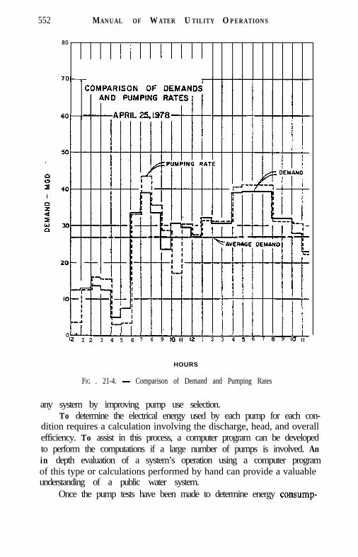
552 MANUAL OF W ATER UTILITY OPERATIONS
80
60'
0I2 I 2 3 4 5 6 7 6 9 1011 12 I 2 3 4 5 6 7 8 9 10 II,
HOURS
FIG . 21-4. - Comparison of Demand and Pumping Rates
any system by improving pump use selection.To determine the electrical energy used by each pump for each con-
dition requires a calculation involving the discharge, head, and overallefficiency. To assist in this process, a computer program can be developedto perform the computations if a large number of pumps is involved. Anin depth evaluation of a system’s operation using a computer programof this type or calculations performed by hand can provide a valuableunderstanding of a public water system.
Once the pump tests have been made to determine energy consump-
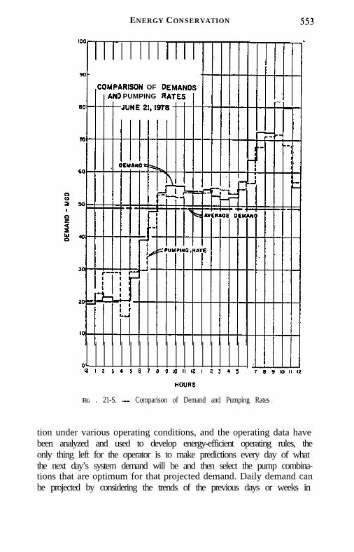
ENERGY CONSERVATION
AAISDN OF 00 PUMPING R
0*I2 1 2 3 I I 6 7 6 9 IO II I2 I 2 3 4 ,
HOURS
FIG . 21-S. - Comparison of Demand and Pumping Rates
tion under various operating conditions, and the operating data havebeen analyzed and used to develop energy-efficient operating rules, theonly thing left for the operator is to make predictions every day of whatthe next day’s system demand will be and then select the pump combina-tions that are optimum for that projected demand. Daily demand canbe projected by considering the trends of the previous days or weeks in

554 MANUAL OF WATER UTILITY OPERATIONS
conjunction with weather forecasts.Before suggesting some general guidelines for efficient pumping op-
eration which can be used to evaluate the current operating proceduresand as possible revisions for future operations, it is important to note thatthe prime responsibility of any water system operator is to provide ade-quate service to all the customers. To satisfy this responsibility often re-quires less than the most energy efficient operating procedures. This con-dition can result from equipment characteristics and system limitations;however, as opportunities arise, modifications can be made that will per-mit more energy efficient operating procedures while satisfying theprime responsibility of adequate service.
General guidelines for the most efficient pumping operation for en-ergy conservation which are frequently suggested are:
1. Use the pump stations that operate against the lowest total heads,and deliver water to consumers by pumping the fewest times possible.
2. Anticipate the required daily pumpage and make efforts to meetdemands with constant-rate pumpage combined with flow to and fromelevated storage.
3. Use the most efficient combination of pumps available at a givenpump station to provide the required flow.
4. Ensure that all valves are completely open during the pumpingoperations.
5. Avoid throttling or bleeding flow between pressure planes withinthe system.
Directly related to pump operating procedures are the elevated stor-age operating procedures. Many water systems control the operation oftheir raw water and high service pumps according to the water levelsin their ground storage and elevated storage tanks. Some water systemsoperate distribution storage facilities by rules of thumb or by maintain-ing a nearly constant reservoir level. Although this practice may be nec-essary in some cases to maintain a reserve of raw water or to maintainadequate pressures in the distribution system, in many cases a full tankis not necessary. This type of operation invariably results in wasted elec-trical energy and money. Water retained in storage facilities must alsobe kept fresh. Therefore, storage reservoirs must be depleted and refilledperiodically. Properly sized and located elevated storage facilities canprovide substantial reductions in the peak rate pumping requirements.
The application of some of these general guidelines can be illustrat-ed with some examples. The need to anticipate the required daily pum-page and to make an effort to meet the demands with nearly constant-rate pumpage with flow to and from storage is illustrated in Figures 21-

ENERGY CONSERVATION 555
4 and 21-5. These illustrations were selected to compare pumping rateswith hourly demands on both an average day and a higher demand day.In both examples, the pumping rates actually exceeded the demand dur-ing the higher use period. This means that the elevated storage tankswere being filled rather than being used to level out the pumping. Onthe higher demand day (Fig. 21-5), the elevated storage tanks were usedduring the highest demand period, but less than one million gallons wereused from storage during the highest two hours.
A second guideline that was evaluated in the development of theseexamples is the use of the efficient combination of pumps available ata given station to provide the required flow. A review of the operationalprocedures used on the average day (Fig. 21-4), indicated that the select-ed pumps were operating in a fairly inefficient range during the earlymorning hours. The efficiencies attained a more desirable level in theevening. The inefficiencies in the early morning hours probably resultsfrom the fact most pumps are selected to operate with the greatest effi-ciency at the higher demand rates. For the variable equipment, the bestselection of pumps may have been made. As an indication of what mightbe achieved in the area of pump selection, if all the pump efficienciesthat were less than 80%, a 3 to 4% on this average day were increasedto at least 80% a 3 to 4% savings in energy could be obtained. If thisdegree of reduction were achieved throughout a year, a more efficientpump for the lower demand rates would pay back in only a few years.Modifications to existing equipment would pay back even sooner.
No evaluation of energy conservation in water systems would becomplete without consideration of pricing. Use of the most favorableelectric rates available will not conserve energy, but it can conserve dol-lars. Most electricity rate structures have at least two components, acharge for power (demand) and a charge for energy (consumption).Electrical demand is the highest average electrical load, expressed inkilowatts, which the metered facility uses during a specific interval oftime, usually 30 min. Electrical consumption is the total monthly amountof electrical energy, expressed in kilowatt hours, that the facility uses.
In a water system, the billing demand for the year is normally setduring the summer months when customer demand for the water is high-est and, consequently, the greatest amount of water production andpumping occurs. The annual cost of electricity can be reduced signifi-cantly if power demand in the summer months can be reduced signifi-cantly. Many electric power companies offer an “off-peak” or “time-of-day” rate to municipal and commercial customers. These rates allow thecustomer to reduce billing by shifting some of its power demand to hours

556 MANUAL OF WATER UTILITY OPERATIONS
of the day when total power demands on the electric utility’s generatingcapacity are relatively low (late night and early morning).
It is difficult to take advantage of off-peak power rates unless thewater system has a substantial amount of either raw-water or finished-water storage capacity. If sufficient storage capacity exists, the utilitycan fill storage with its largest pumps during off-peak hours, then usesmaller pumps, which use less power in conjunction with a drawdownof water in storage, to meet peak daily needs of water customers.
Some power companies also offer interruptible power service con-tracts to customers. Water systems with ample storage and/or engine-driven pumps, and that have the ability to sustain adequate service towater customers during summer peak water use days while operatingunder reduced electric power, are candidates for such contracts. Thesecontracts allow the power company to interrupt or reduce power for upto a specified number of hours during a summer day and up to a specifiedmaximum number of hours per year. For the privilege of being able tointerrupt or reduce power to the water system, which helps the powercompany avoid blackouts, the power company gives the water utility anegotiated credit on its power bills. Prior to implementation of an off-peak method of operation, a thorough evaluation of the operational andeconomic ramifications should be undertaken.
In conclusion, the five general steps that a water system should con-sider in the determination of how the energy requirements can be re-duced are:
1. Determine how much energy is being used.2. Determine where the energy is being used.3. Evaluate the physical characteristics of the primary energy con-
suming equipment.4. Evaluate the operational procedures that involve this equipment.5. Revise the operational procedures that involve this equipment
while continuing to provide satisfactory service.