texas fleet specifications and requirements - … attachments/071-072...a.4 general information and...
TRANSCRIPT

Texas Comptroller of Public Accounts
Statewide Procurement Division
Texas Fleet Specifications and Requirements
Effective Date: September 1, 2017 – October 31, 2018

1
TABLE OF CONTENTS
A.1 SCOPE .................................................................................................................................................................... 2 A.2 DEFINTIONS AND ABBREVIATIONS: ..................................................................................................... 2 A.3 APPLICABLE SPECIFICATIONS, STANDARDS, RULES, AND REGULATIONS: ............................... 3 A.4 GENERAL INFORMATION AND REQUIREMENTS: ............................................................................... 4 A.5 CERTIFICATION, COMPLIANCE, AND MANUFACTURER BUILD-OUT/ORDER DEADLINES: .... 7 A.6 INSPECTION: ................................................................................................................................................ 8 A.8 MANUFACTURER’S STATEMENT OF ORIGIN (MSO): ......................................................................... 9 A.9 APPLICATION FOR TEXAS TITLE (Form 130U latest version): .............................................................. 9 A.10 PRE-DELIVERY SERVICE: ....................................................................................................................... 9 A.11 WARRANTY, SERVICE, AND SERVICE CONTRACTS: ....................................................................... 9
SECTION B - AUTOMOBILE AND TRUCK REQUIREMENTS AND SPECIFICATIONS ................................. 11 B.1. GENERAL REQUIREMENTS: .................................................................................................................. 11 B.2. GENERAL PURPOSE AUTOMOBILES: .................................................................................................. 12 B.3 SPECIAL PURPOSE AUTOMOBILES - LAW ENFORCEMENT (LE) PURSUIT OR SPECIALSERVICE VEHICLES: ....................................................................................................................................... 23 B.4. UTILITY VEHICLES (CARRYALLS, 4-WHEEL DRIVE UTILITY, AND CARGO VANS): ............... 35 B.5. PASSENGER VANS, LIGHT-DUTY:........................................................................................................ 49 B.6 LIGHT-DUTY TRUCKS: ............................................................................................................................ 56 B.7. CUTAWAYS: ............................................................................................................................................. 89 B.8 MEDIUM-DUTY TRUCKS: ........................................................................................................................ 92 B.9. HEAVY-DUTY TRUCKS: ....................................................................................................................... 145
SECTION C – ALTERNATIVE FUEL VEHICLE REQUIREMENTS AND SPECIFICATIONS ........................ 174 SECTION D – OPTIONAL EQUIPMENT SPECIFICATIONS .............................................................................. 180 SECTION E - REQUIREMENTS FOR DUMP BODIES - CONTRACTOR'S, PLATFORM, AND STAKE BODIES ..................................................................................................................................................................... 205 SECTION F - REQUIREMENTS FOR STATIONARY PLATFORM AND STAKE BODIES ............................. 211 SECTION G - REQUIREMENTS FOR UTILITY BODIES .................................................................................... 212 SECTION H – SPECIAL EQUIPMENT – PARA-TRANSIT BODY & WHEELCHAIR LIFT ............................. 214 SECTION I –SPECIAL EQUIPMENT–PARA-TRANSIT LOW-FLOOR BODY & WHEELCHAIR RAMP ...... 219

2
SECTION A – GENERAL INFORMATION, REQUIREMENTS, AND CONDITIONS
A.1 SCOPEThis specification and requirements document describes the majority of automobile and truck categoriesrequired by the various agencies and political subdivisions of the State of Texas. Tables of minimum requirements for each category automobile and truck covered by this specification are included. Specifications pertaining to the make and model of the automobile or truck available from the various manufacturers are included in the tables.
A.2 DEFINTIONS AND ABBREVIATIONS:The following definitions and abbreviations are used throughout this specification document:
Abbreviation Definition 4WD Four Wheel Drive ASE National Institute of Automotive Service Excellence ASTM American Society for Testing and Materials. AWD All-Wheel Drive (May not be suitable for off road terrain. Check manufacturer's literature) BCI Battery Council International. CARGO LENGTH Length in inches behind the first row of seats CCA Cold Cranking Amps CFR United States Code of Federal Regulations. CNG Compressed Natural Gas CPA (COMMISSION) Comptroller of Public Accounts
CONTRACTOR A manufacturer’s representative or dealer authorized to make sales and supply parts and service in Texas.
DMV Texas Department of Motor vehicles DOT United States Department of Transportation. DPS Texas Department of Public Safety. EPA United States Environmental Protection Agency. FFV Flex Fuel Capable FMVSS United States Federal Motor Vehicle Safety Standards. FWD Front Wheel Drive GAWR Gross Axle Weight rating GCWR Gross Combination Weight Rating GVWR Gross Vehicle Weight Requirement IFB Invitation for Bids. LPG Liquefied Petroleum Gas MANUFACTURER A fabricator of automobile trucks, bodies, chassis, or components. MPG Miles Per Gallon MSO Manufacturer’s Statement of Origin NGV Natural Gas Vehicle. NTEA National Truck Equipment Association. OEM Original Equipment Manufacturer: OSHA United States Occupational Safety and Health Administration.
PAYLOAD Approximate payload allowance is defined as (GVWR - Curb Weight of the vehicle) and includes weight of all passengers including driver.
PSI Pound Per Square-Inch RBM Resistive Bending Movement Rating for Frames RRC Railroad Commission of Texas

3
RPM Revolutions Per Minute
RWD Rear Wheel Drive (Also all 2-Wheel Drive vehicles will be assumed to be RWD unless specified)
SAE Society of Automotive Engineers. TCEQ Texas Commission on Environmental Quality TDCJ Texas Department of Criminal Justice TxDOT Texas Department of Transportation Up-fitter Sub-Contractor providing services to install specialized components and equipment VER Vehicle Emissions Rating VIN Vehicle Identification Number ZEV Zero-emissions Vehicle
As Shown The term “As Shown” on each Specification tables equals per Manufacturer’s standard per Model as applicable to each Series
A.3 APPLICABLE SPECIFICATIONS, STANDARDS, RULES, AND REGULATIONS:1.1. EXHAUST EMISSION STANDARDS: Vehicles furnished to this specification shall meet the applicable
requirements of the EPA’s Exhaust Emission Standards (40 CFR 85, 86, and 88) and all revisions as issued under authority of the Clean Air Act.
1.2. FEDERAL MOTOR VEHICLE SAFETY STANDARDS (49 CFR 571): Automobiles and trucks shall meet or exceed the minimum requirements of this specification and all applicable requirements of the FMVSS. All requirements of this specification shall be met unless they are in conflict with the applicable FMVSS.
1.3. HORSEPOWER AND WHEELBASE LIMITATIONS (Section 2158.003, Texas Government Code: “A state agency/entity may not purchase or lease a vehicle designed or used primarily for the transportation of persons, including a station wagon that has a wheelbase longer than 113 inches or that has more than 160 SAE net horsepower, except that the vehicle may have a wheelbase of up to 116 inches or SAE net horsepower of up to 280 if the vehicles will be converted so that it is capable of using compressed natural gas or another alternative fuel…” “The wheelbase and horsepower limitations prescribed by this subsection do not apply to the purchase or lease of a vehicle to be used primarily for criminal law enforcement or a bus, motorcycle, pickup, van, truck, three-wheel vehicle, tractor or ambulance.”
1.4. LICENSING: Contractor and its subcontractors must have all appropriate licenses required by the Texas Occupations Code, the Texas Transportation Code, and the regulations of the Texas Department of Motor Vehicles including 43 TAC Chapter 215.
1.5. OTHER SPECIFICATIONS AND STANDARDS: Reference to specifications, standards and test methods shall be to those in effect on the date of the Invitation for Bids (IFB). The following publications form a part of this specification to the extent that they meet all of OSHA’s requirements and others as specified herein 1.5.1. AMERICAN SOCIETY FOR TESTING AND MATERIALS (ASTM), 1916 Race Street,
Philadelphia, Pennsylvania 19103: ASTM A 606 – Standard Specification for Steel Sheet and Strip, Hot-Rolled and Cold-Rolled, High Strength, Low-Alloy, with Improved Corrosion Resistance.
1.5.2. NATIONAL TRUCK EQUIPMENT ASSOCIATION (NTEA), 25900 Greenfield Rd. #410, Oak Park, Michigan: NTEA– Hydraulic Conversion Hoist Classification Charts.
1.5.3. SOCIETY OF AUTOMOTIVE ENGINEERS (SAE), 400 Commonwealth Drive, Warrendale, Pennsylvania 159096: SAE J377 – Standard for Performance of Vehicle Traffic Horns. SAE J544b – Recommended Practice for Starting Motor and Generator Curves. SAE J551/12 – Vehicle Electromagnetic/Interference (EMI/RF) March, 1994 or latest revision.
1.5.4. SUPERINTENDENT OF DOCUMENTS, U.S. Government Printing Office, Washington, D.C. 20402: CFR, Title 40, Part 85 – Control of Air Pollution from New Motor Vehicles and New Motor Vehicle Engines, Environmental Protection Agency.

4
DOT, Title 49, Part 393 – Liquid Fuel Systems of Commercial Motor Vehicles, Certification of Fuel Tank. FMVSS (49 CFR 571):
FMVSS No. 108 – Lamps, Reflective Devices and Associated Equipment. FMVSS No. 126 - Electronic Stability Control Systems; Controls and Displays FMVSS No. 209 – Seat Belt Assemblies for Passenger Cars, Multipurpose Passenger Vehicles, Trucks and Buses. FMVSS No. 210 – Seat Belt Assembly Anchorages – Passenger Cars, Multipurpose Passenger Vehicles, Trucks and Buses. FMVSS No. 301 – Fuel System Integrity.
FEDERAL STANDARDS: No. 595a – Colors. No. TT-C-5208 – Coating Compound, Bituminous, Solvent Type, Underbody (for Motor Vehicles). U.S. OCCUPATIONAL SAFETY AND HEALTH ADMINISTRATION (OSHA): Construction Safety and Health Regulations, Section 1926.601 – Motor Vehicles.
1.6. STATE OF TEXAS: 1.6.1. RAILROAD COMMISSION OF TEXAS (RRC), Liquefied Petroleum Gas Division, P.O. Box
12967, Austin, Texas 78711-2967:
Regulations for Compressed Natural Gas (current edition). Safety Rules: Liquefied Petroleum Gas Division (current edition). 1.6.2. TRANSPORTATION CODE Chapter 5. 1.6.3. TEXAS OCCUPATIONS CODEChapter 2301
A.4 GENERAL INFORMATION AND REQUIREMENTS: 1.1. ACCESSORIES, REQUIRED AND OPTIONAL: Unless otherwise specified in the IFB, current vehicle
manufacturer’s standard advertised/published accessories and other options shall be chassis- factory installed, on all vehicles except Class 3 – 5 (medium-duty) cab and chassis units, but including Class 1 and 2 (light-duty) cab and chassis units. An individual option shall be factory installed whether the option is available separately, or as part of an option package. Contractor shall provide OEM options when options are available as OEM. If agency approves aftermarket parts, aftermarket accessories installed must meet the requirements of this specification. Where available, the Contractor shall provide the manufacturer’s current standard and optional feature codes as they align with these specifications. When only provided as part of an option package, all package items, including the individual option shall be provided. Vehicle manufacturer’s standard advertised/published accessories for medium-duty cab and chassis units shall be chassis-factory installed. Requested optional equipment on medium-duty cab and chassis units shall be furnished and installed by the chassis manufacturer (if available) or they shall be furnished and installed by dealer or other manufacturers, provided all specified minimum requirements are met. All installed options shall be priced including the installation cost. Dealer bids on all non-OEM/after-market options on this contract shall be accompanied by the item’s manufacturer part/model/series number to be provided at the given price. *NOTE: All options shall be OEM, unless otherwise noted. Furthermore, adding some options to vehicles may result in a change in vehicle model (within a particular series).*
1.2. BATTERIES: OEM Standard Batteries with designed maximum reserve capacity and CCA required. 1.3. COMPARABLY EQUIPPED VEHICLES: An attempt has been made to ensure that manufacturer’s models
in each Series are furnished with comparable equipment (whether optional or standard as provided by the manufacturer). Any imbalance in the requirements for a listed series, i.e., an item that is an optional accessory for one brand and standard on another, should be called to the attention of the Statewide Procurement Division immediately.
1.4. DEALER BODY/COMPONENT REQUIREMENTS: Dealer shall submit manufacturer’s current, regularly
published literature on the body, toolbox, and other aftermarket components offered. Literature shall be sufficiently detailed to permit CPA or the Customer to determine if the items offered meet specified requirements.

5
• If the bodies/components are discontinued by the manufacturer or become otherwise unavailable, dealer shall submit literature on proposed alternate(s) for CPA or the Customer’s approval.
• The Contractor shall (within 3 business days of request) furnish CPA or the Customer written verification that the selected up-fitter has read, understands, and will comply with all specification requirements, including delivery timelines. The verification shall be signed by a representative of the selected up-fitter. Contractor shall submit written verification from any additional or alternate up-fitter(s) to be used under the contract.
1.5. EQUIPMENT MOUNTING: No equipment mounted on State of Texas vehicles or chassis shall, under any circumstances, be welded to the vehicle frame at any point between the front of the front spring hanger and the rear of the rear spring hanger. Also, all holes for bolting must be drilled and not burned. Further, no holes shall be drilled in top or bottom flange of truck frame unless drilling is confined to the section behind the rearmost attachment of the rear spring hangers or for pre-formed factory-made frame rail bolt holes for subsequent body installation. Welding or torch cutting shall be confined to “boxing” the rear end of truck frame (as required for dump equipment to allow full dumping angle). All such work shall be confined to area behind rear spring hangers. Mounting strip between hoist sub-frame of dump body and chassis frame may have flame cut holes to countersunk rivets on truck frame. Chassis frame rivets shall not be removed or cut flush with frame for any reason. Any mounting of aftermarket bodies or equipment may require special wheelbase and cab/axle dimensions to achieve correct weight distribution. Dimensions will be verified by Customer, and aftermarket vendor to accommodate intended use of vehicle. All mounting of special after-market equipment shall meet manufacturer’s installation requirements, aftermarket equipment manufacturer’s requirements, and all state and federal standards.
• Corrective action or replacement due to damage to the vehicle or chassis from non-standard ornegligent mounting of equipment shall be the responsibility of the Contractor. Mounting ofaftermarket bodies or equipment to chassis may require special wheelbase and cab to axle dimensionsto achieve correct weight distribution. If the Contractor discovers a need to change the orderedvehicle dimensions, the new dimension will be confirmed by Customer and CPA, and the purchaseorder adjusted to accommodate the intended use of vehicle. OEM shall be responsible for the vehicleand shall ensure the vehicle conforms to all applicable Motor Vehicle Safety Standards Per CFR 49,Part 567.sa
1.6. SAFETY PLAQUES OR DECALS: Safety plaques or decals shall be furnished on vehicles and bodies, and shall be affixed at any hazardous area. The safety plaques or decals shall describe the nature of the hazard, level of hazard seriousness, how to avoid the hazard, and the consequence of human interaction with the hazard. Permanent plaques are preferred to decals. Type, size and locations of product safety plaques or decals shall be in accordance with ANSI 535.4-1995, or latest revision thereto.
1.7. GRILLE GUARDS AND HEADACHE RACKS: Grille guards and headache racks are required to have, permanently affixed, model and manufacturer identification (matching the description provided by the vendor at the time of bidding). The option price shall include the installation cost.
1.8. LAMPS, SIGNALS, AND REFLECTORS (SERIES 650C THROUGH 1201D): Reflectors and clearance, side-marker and identification lamps for Series 650 through 990 vehicles shall also meet the following additional requirements. Reflectors must be housed type with screw or bolt type mounting; stick-on type is not acceptable. Surface-mounted clearance and side-marker lamps shall be metal armored type. Recess-mounted side marker and clearance lamps must be recessed sufficiently to provide protection for the lens. Lenses for side-marker and clearance lamps shall be secured to the lamp by a fastening method which require a tool to remove the lens.
1.9. LICENSE PLATE ATTACHMENT: Each vehicle, except cab and chassis units, shall be furnished with means and adequate space for attaching the front and rear license plate without modification. Illumination provided for the license plate shall be in compliance with Texas motor vehicle laws.
1.10. LOGOS AND DECALS: Contractor shall not place decals or markings of any type pertaining to advertisement other than manufacturer’s name or model designation normally installed by manufacturer on equipment delivered to any state agency or entity.

6
1.11. MANUALS: Contractor must include in each vehicle an owner’s or operator’s manual at the time of delivery. This will include all standard manufacturer/Contractor literature normally furnished and as required by law with the purchase of a new vehicle. In addition to the print version of the manual, the OEM or Dealer shall provide these documents in an electronic format or a link to their website for download. For Class 6, 7 and 8 vehicle fleet repair and maintenance manuals, electronic format shall be acceptable.
1.12. MUD FLAPS: See Section 8.1.3 for mud flaps prescribed by law.
1.13. NEW MODELS: The vehicles furnished under this specification shall be the latest production model or newer and shall be of good quality workmanship and material. The Contractor represents that all units offered under this specification shall meet or exceed the minimum requirements specified for each vehicle series listed. Contractor shall hold prices for the entire term of the contract if a new model is available during the term of the contract.
1.14. ODOMETER STATEMENT: The Truth in Mileage Act requires the selling dealer to furnish a complete odometer statement to the purchaser. This statement must be complete and shall include mileage accrued at the point of delivery. The delivered unit shall not have more than 300 miles on the odometer, unless previously agreed upon in writing with the purchaser. In addition to the signature of the seller/agent certifying the odometer reading, both the dealership and the name of the agent shall be printed on the Odometer Disclosure Statement. The odometer statement on the MSO will satisfy this requirement. If a vehicle is delivered with more than three hundred miles on the odometer, without prior written approval from the Customer, the Customer will have the option to reject the vehicle without penalty to the Customer. NOTE: ODOMETER STATEMENT IS NOT REQUIRED ON TRUCKS WITH A GROSS VEHICLE WEIGHT RATING OF 16,000 POUNDS OR MORE. An exception for Series 960D through 1286D: Odometers shall not have more than 1,500 miles on the odometer.
1.15. SERVICING AND EQUIPPING: Contractor shall furnish automobiles and trucks meeting or exceeding the minimum requirements in the appropriate Series table and equipped exactly as listed for makes and models in the various tables of this specification and with any other requirements specified in the IFB. The vehicles shall be completely assembled, serviced, adjusted, and all equipment including standard and optional equipment shall be installed and the units made ready for continuous operation. If vehicles are delivered not made ready for continuous operation, it will be the Contractor’s responsibility to have the units made ready for continuous operation prior to acceptance. It shall not be the Customer’s responsibility to arrange for the units to be made ready, including transporting units to local dealership for warranty repairs prior to acceptance. Standard equipment means those components and accessories usually and ordinarily furnished without additional cost on regular production models.
1.16. SPEEDOMETER: Each vehicle shall be equipped with a speedometer having an odometer as an integral part. The speedometer drive mechanism must be properly calibrated in relation to each axle ratio and tire size to give accurate readings.
1.17. TIRES: All tires shall be new and the tread style shall be the tire manufacturer’s standard design and the brand normally furnished on regular production orders, unless otherwise specified in the Invitation for Bid. All tires shall be “ORIGINAL EQUIPMENT LINE” quality and have not less than a “B” heat rating or minimum heat rating specified by the vehicle manufacturer. NOTE: UNLESS OTHERWISE SPECIFIED IN THE IFB, RAISED WHITE LETTERS ARE NOT ACCEPTABLE ON LIGHT-DUTY TRUCK AND TRUCK TYPE TIRES. VEHICLES EQUIPPED WITH RH5 DEGREE MULTIPLE PIECE CENTER-LOCKING RIMS ARE NOT ACCEPTABLE. Tires should have a manufacturer production date of not older than 12 months of the production date of the cab and chassis.
1.18. WIRING: With the exception of factory-installed wiring, all electrical wiring shall be insulated and enclosed in a fibrous loom, plastic loom, or flexible conduit for protection from external damage and short circuits. It shall be securely fastened at sufficient intervals to prevent sagging and to ensure clearance of mechanical parts.

7
Routing of the wiring through the cab, frame, body, compartment box, and the like shall be placed in such a manner so as not to interfere with normal operation and use, or present a safety hazard. Rubber grommets shall be used wherever wires, hoses or harness pass through metal. (Refer to Section E.4.6 for the wiring requirements for dump bodies.)
1.19. SAFETY NOTICES AND RECALLS: All safety notices and recalls shall be mailed to the entity’s address on the purchase order for the destination of goods or other contact noted on the purchase order, (i.e. Fleet Recall Coordinator).
1.20. FLEET NUMBERS: The assignment of manufacturer’s fleet numbers to ordering agencies shall be the sole responsibility of the awarded Contractor.
1.21. TAX, TITLE, AND LICENSE: All on-road vehicles shall be delivered with Dealer Temporary license plates/tags. Customer will be responsible for any applicable tax, title, and license fees, in addition to vehicle purchase price. All vehicle contract prices exclude tax, title, and license. It shall be the responsibility of the Customer to inform the Contractor of their status as exempt or non-profit, so that Contractor may collect applicable taxes and fees, and process any required licensing and titling applications. Customers shall direct any questions concerning applicable tax, title, and license fees to their appropriate County Tax Assessor/Collector Office or the Texas Comptroller of Public Accounts at 1-800-252-1382.
1.22. EPA EMISSION LEVEL: OEM/Contractor must provide the published EPA Greenhouse Gas Score including appropriate references to Tier and Bin. OEM/Contractor must provide separate scores if they vary by transmission type on the same model. Alternate engines, with an emission level different from that originally quoted, must have prior approval of the Customer. Emission level changes to vehicles on state contract require prior written approval of the CPA and will be documented through an addendum to the specification and changed in the automated contract. This information is published by the OEM and is required for the State’s fleet management software program. EPA does not rate work vehicles
E85 FLEX FUEL ENGINES (FFV): All vehicles are to be delivered with E85 Flex fuel engines if available from OEM at no additional cost to dealers.
A.5 CERTIFICATION, COMPLIANCE, AND MANUFACTURER BUILD-OUT/ORDERDEADLINES: 1.1. DELIVERY TIME FRAMES: ( Calendar Days) 150 Days 180 Days 220 Days 300 Days General Purpose Automobiles
Special Purpose Automobiles (LE)
Medium and Heavy Duty Chassis with Optional Bodies *****See Series with 300 days exceptions
Exceptions: Series 960D, 970D, 985D, 986D, 990D, and 1000D, 1200D, 1202D, 1286D with 300 days delivery
Carryalls, Utility Vehicles, Cargo Vans
OEM Alternative Fuel Vehicles
Passenger Vans, Light Duty Light Duty and Crew Cab Trucks Light- and Medium-Duty Chassis w/No Bodies
FREIGHT: All units to be F.O.B. destination, freight prepaid and allowed. . Receiving entities do not pay delivery or destination charges or surcharges.
Extensions of delivery may be granted on a case by case basis by the Customer, upon written request by awarded Contractor Written requests for delivery extensions shall include Customer requisition/ purchase order number(s), reason for extension, and time frame in number of days needed for extension, and must precede the late delivery of the vehicle.

8
LATE DELIVERY FEE: The Customer will have the option to charge the Contractor a fee of $50 per vehicle per day for late delivery. Late fee applies ONLY when Contractor has not requested and received PRIOR WRITTEN approval from the Customer, to make delivery after the number of days established by the contract or the purchase. Contractors must ensure that excessive mileage is not put on vehicles during the delivery process. NOTE: Providing vehicle(s) which do not meet all specification requirements does not constitute delivery, and the late fee will continue to accrue until the Contractor delivers vehicles in full compliance with the specifications to the Customer’s FOB point. The Customer will have the option to deduct any accumulated late delivery fees from the invoice.
1.2. SUBMITTAL OF MANUFACTURER BUILD-OUT AND ORDER DEADLINES: Awarded Contractor shall furnish CPA with order deadlines in writing by vehicle series number a minimum of three weeks prior to deadline. Order deadlines not designated by series number will not be accepted. Awarded Contractor shall be responsible for fulfilling all purchase orders issued pertaining to each series in which a deadline has not been provided in accordance with the above requirements. Only one order deadline will be permitted for each vehicle series. Model year build out order deadline will be posted for each manufacturer’s model as they become available. After model year build out deadline, “in stock” vehicles may be available through the contract from the awarded contract Contractors. Agencies should contact the awarded Contractor for availability and delivery for orders placed after the deadline has passed. Receiving entities will have the option, if offered, of accepting the next year’s model at the current awarded pricing. When this occurs, the Contractor will provide written notification of expected delivery dates to the Customer.
1.3. STATE OF TEXAS VEHICLE DELIVERY DATA SHEET: At delivery, Contractor shall provide with each vehicle a State of Texas Vehicle Delivery Data Sheet to include the following information. Additional information may be requested during the life of the contract. SUMMARY: Purchase Order Number, Requisition Number, delivery date, purchase cost, odometer ready at delivery, warranty expiration (date & miles or delayed). IDENTIFICATION: Vehicle Identification Number (VIN), year, make, model. READINGS: meter type (miles or hours), primary fuel type, secondary fuel type, fuel capacity (with units), engine oil capacity (with units), and transmission fluid capacity (with units). RATINGS: Gross Vehicle Weight Rating (GVWR), Vehicle Emissions Rating (VER), EPA Miles per Gallon (MPG) Rating, Engine Family Code. SPECIFICATIONS: Number of tires, tire size, wheelbase, transmission type (manual or automatic), drive type (2-wheel, 4-wheel, etc.), engine size, number of cylinders
1.4. OEM VEHICLE WINDOW STICKER/DECAL: The OEM Window Sticker/Decal as affixed by the manufacturer shall be considered part of the required delivery documents. The Contractor shall ensure this document is safeguarded during the pre-delivery and delivery processes and must replace it if it is destroyed or lost. This requirement does not apply to medium duty (Series 960 and above) and heavy duty trucks.
A.6 INSPECTION: 1.1. VEHICLE INSPECTION: The Contractor shall have each vehicle (except cab and chassis units delivered
without bodies) properly inspected in compliance with Texas motor vehicle laws.
1.2. ENTITY CHECK-IN INSPECTION: Customer should check the vehicle upon delivery to ensure compliance with this specification and any other specific requirements. The Contractor shall deliver with the vehicle a vehicle-specific line-setting ticket, manufacturer’s invoice, Application for Title (Form 130U latest version), and MSO or any official documentation to verify the fact that ordered options, GVWR rating, and other requirements have been met. The ship to address shall be identified on the form 130U. 1.2.1. Failure to provide this information may cause the delay of Customer processing payment. Payment
will be made within 30 days after vehicle’s acceptance or receipt of correct invoice, whichever is later. Acceptance will not be made, nor payment initiated on vehicles failing to meet specifications (unless they are brought into full compliance), and all necessary documents (i.e. MSO, 130U, odometer statement, etc.) are received by the Customer.

9
1.2.2. Unless otherwise specified in the Invitation for Bid, agencies are permitted a maximum of 5 working days to complete this inspection.
A.8 MANUFACTURER’S STATEMENT OF ORIGIN (MSO):Awarded Contractor shall furnish the Customer a MSO (Certificate of Title will not meet this requirement). Avehicle shall not be considered “delivered” until the MSO is received by the Customer. MSO shall either befurnished at the time of vehicle delivery or within 48 hours of vehicle delivery to the Customer and shall be madeout in the name of the individual entity (see NOTE below), providing the following:
1. GVWR for the particular model specified, or;2. The GVWR required for the entity’s written exception, or;3. A greater GVWR required by extra equipment, and;4. Nominal weight rating (in tons),5. Odometer Disclosure Statement.
NOTE: Contractor should contact the Customer to obtain proper entity name and address for assignment of the MSO
A.9 APPLICATION FOR TEXAS TITLE (Form 130U latest version):Awarded Contractor shall furnish the Customer assigned and completed Form 130U. A vehicle shall not beconsidered “delivered” until the 130U is received by the Customer. Form 130U shall either be furnished at the time of vehicle delivery or within 48 hours of vehicle delivery to the Customer and shall be made out in the name of the individual entity (see NOTE below), providing the following: NOTE: The latest version of the Form 130U is available at the Texas Department of Motor Vehicles website.
A.10 PRE-DELIVERY SERVICE:All units (including complete vehicles and cab and chassis units) shall include new vehicle pre-delivery service.
1.1 The following service shall be performed before the units are delivered to the Customer: 1.1.1 All fluid levels checked and maintained with the proper grade and type of fluids. 1.1.2 Pre-delivery inspection and service on chassis. 1.1.3 The interior and exterior of units shall be clean and freshly washed at time of delivery. 1.1.4 A minimum of 1/4 tank must show on the fuel gauge when delivered. 1.1.5 The delivered unit shall not have more than 300 miles on the Odometer, unless previously
agreed upon in writing with the purchaser.
1.2 When so specified in the Invitation for Bid, the Contractor or their representative who is responsible for the final delivery shall attach signed certificates to the units stating that the above service was performed and that inspection indicates they are in good condition and ready for delivery.
1.3 Unless specifically permitted by the Customer, vehicles shall be equipped with all accessories as stated in the purchase order prior to delivery. Generally, the up-fitting or servicing of ordered vehicles on the premises of the Customer is not permitted.
1.4 All shipping tickets shall reference the Customer’s requisition/purchase order number(s) and accompany each delivery shipment. If shipping tickets are received without the requisition/purchase order number(s), Customer may reject the delivery.
1.5 Window sticker shall remain attached to the vehicle.
1.6 The Contractor shall provide an official and acceptable weight certificate when applicable and required for vehicle registration. This section excludes cab and chassis vehicles delivered for later up-fit.
A.11 WARRANTY, SERVICE, AND SERVICE CONTRACTS:1.1 WARRANTIES, ACCESSORIES: The awarded Contractor shall furnish a copy of the manufacturer’s
standard warranty on minor accessories such as batteries and tires and major accessories such as Dump, Stake, Platform and Utility Bodies, side-mounted tool compartments and tool boxes at the time of delivery to the Customer.
1.2 WARRANTIES, NEW VEHICLE: The awarded Contractor shall furnish the Customer a New Vehicle

10
and/or Chassis Manufacturer’s Warranty which will be honored by any of the manufacturer’s authorized dealers. This warranty shall be comparable to or better than those offered to the general public. Passenger cars and light-duty trucks shall have a minimum warranty offered to the general public (not commercial trade). Minimum warranty shall be at least 3 years/36,000 miles bumper to bumper with a power train warranty of 5 years/100,000 miles. Warranty starts when vehicle is delivered.
Exception: for Series 960D, 970D, 985D, 986D, 990D, 1000D, 1200D, 1202D, and 1286D: warranty shall be 2 years/unlimited miles. If any part of the manufacturer's standard warranty exceeds 24 months, unlimited mileage, then that part of the manufacturer’s standard warranty shall be in effect.
1.3 Contractor shall furnish a complete copy (detailing coverage and exclusions) of the new vehicle warranty to agencies with each vehicle delivered. Contractor shall also provide an additional copy within 10 working days after request.
1.4 WARRANTIES, DEDUCTIBLES: All warranty repairs shall be performed without assessing the Customer warranty deductibles. Awarded Contractor shall be responsible for any warranty deductibles required for warranty repairs.
1.5 WARRANTIES, DELAYED: Delayed warranties must be available for all vehicles. Warranty start date shall be effective the day the completed unit is placed into service. Contractor shall furnish a delayed warranty card/document with each unit delivered, advising entity personnel of the procedures to be followed for obtaining delayed start of warranty coverage.
NOTE: If Contractor fails to arrange for delayed warranty with OEM, Contractor is responsible for all costs incurred to make appropriate repairs at any dealership in Texas.
1.6 WARRANTIES, DEALER INSTALLED ITEMS: Contractor shall warrant all dealer installed items for quality and workmanship. Warranty shall include 100% coverage for all options, components and labor.
1.7 WARRANTIES, AFTERMARKET ALTERNATE FUEL CONVERSION: Aftermarket fuel conversion means the conversion of an OEM vehicle to operate in its normal capacity or design using an alternative fuel such as LPG or CNG by a company licensed by the Railroad Commission, is certified by the Environmental Protection Agency (EPA), and has at least one ASE certified technician. With an after-market fuel conversion, the company completing the conversion shall be responsible for fuel control issues/problems. If the maintenance program is followed and maintenance is performed by an ASE certified technician, the conversion shall be warranted for 3 years/36,000 miles, whichever comes first. Warranties for components (i.e. tanks) greater than 3 years / 36,000 miles shall be passed on to the Agency. The conversion shall not void any other warranty. The OEM warranty will remain intact unless it is determined that the failure of an OEM part is attributed to an aftermarket fuel conversion. In case of warranty work on an engine converted to use LPG or CNG, it shall automatically become the Contractor's responsibility. The Contractor will arrange, with the permission of the owner, for the vehicle to be repaired by an OEM Certified technician, at an OEM or other facility chosen by the owner, at no cost to the owner. A copy of the conversion equipment manufacturer's warranty and the Contractor's supplemental warranty shall be provided to the Customer at the time of vehicle delivery. Payment for the vehicle (s) cannot be processed until these documents are provided. Major warranty repair work means major repair to the engine due to operation of the engine on LPG or CNG. All conversion components shall be covered. Diagnosis of the actual repairs required will be the responsibility of the Contractor. The vehicle(s) will be made available at the location designated by the owner. The repair work may be performed by the Contractor or his authorized OEM certified representative.
1.8 COMPLIMENTARY SERVICE: If the manufacturer offers a complimentary service agreement with the purchase of a new vehicle, that service shall be included with all vehicles purchased under the contract.
11
SECTION B - AUTOMOBILE AND TRUCK REQUIREMENTS AND SPECIFICATIONS
B.1. GENERAL REQUIREMENTS: 1.1. STANDARD MODELS: The vehicles listed in the following sections are the chassis manufacturer's
standard models for the latest model year available and shall be furnished complete with all standard equipment and factory-installed accessories listed in the manufacturer's printed literature for the respective unit, unless listed in the options list of this specification and the option is not listed on the IFB. The items are minimum requirements and shall be provided whether shown as optional or standard equipment by the manufacturer.
1.1.1. Bids should be submitted for regular package vehicles, not special service packages (unless specifically requested).
1.2. ALTERNATIVE FUEL REQUIREMENTS: Specifications for Alternative Fuel Vehicles are listed in Section C. (See Options 779-794 for availability)
1.3. ADDITIONAL EQUIPMENT: Additional equipment, in addition to standard equipment required for a particular application, is listed immediately below the "Minimum Requirements Tables" of each vehicle Series.
1.4. OPTIONAL EQUIPMENT AND ACCESSORIES: Optional equipment and accessories are listed in Section E. and shall be furnished when so specified in the IFB.
NOTE: Adding some options to vehicles may result in a change in vehicle model (within a particular series).
1.5. STANDARD EQUIPMENT: A list of standard equipment required on each approved model listed for a vehicle Series precedes the "Minimum Requirements Tables" in each section.
1.6. TRUCK AND VAN BODY SPECIFICATIONS: Dump, Stationary, Utility and Para-transit Body and related body equipment specifications are listed in Sections E, F, G and H.
1.7. VEHICLE SERIES DESIGNATIONS: The automobiles and trucks meeting the requirements of this specification have been classified and numbered into Series/Categories.
1.8. ENGINE SUFFIXES: Suffix letters indicate engine type as follows:
A=4 cylinder B=5/6 cylinder C=6/8 cylinder D=diesel G=gasoline
H=Hybrid ALT=Alternative Fuel HX=Plug-in Hybrid BLE/CLE=Law Enforcement (LE) Pursuit or Special Services Vehicle

12
B.2. GENERAL PURPOSE AUTOMOBILES: Unless specified, all units shall be furnished complete with standard equipment and factory-installed accessories as listed in the manufacturer's printed literature for the models specified herein (see Section A.4.1 and Section B.1 in this document). The following items are minimum requirements for the models specified herein and shall be provided whether shown as optional or standard equipment by the manufacturer. The following are some of those standard features or additional features as listed for these models. Note any additional requirements following the table for each Series number. These additional requirements listed below any table are in addition to, the following general requirements for General Purpose Automobiles: The list below displays required features on vehicles under this section and ordering entities shall not pay additional for them.
2.1. Body: 2.1.1. Air Bags: Required. Manufacturer’s standard to include side curtain/impact airbags if available
from manufacturer. 2.1.2. Air Conditioning: Required. Manufacturer's standard. 2.1.3. AM/FM Radio: Manufacturer's standard. 2.1.4. Covering, Luggage Compartment: The luggage compartment floor shall be covered with a
vinyl, rubber, or fiber type mat. 2.1.5. Heater and Defroster: Integral, OEM Standard 2.1.6. Jack, Handle, and Lug Wrench 2.1.7. Power Package: Includes power windows, power locks, power mirrors, cruise control, and tilt
steering wheel. (Option No. 87 to delete entire power package) (Option No.87 is not available from Nissan.)
2.1.8. Spare Wheel (Manufacturer’s full-size spare wheel & tire, where available). 2.1.9. Windshield Wipers: Dual electric 2-speed type with intermittent feature windshield washers. 2.1.10. Upholstery: Cloth standard (Select Option No. 258, for vinyl seat fabric). 2.1.11. Tires: Radial type tubeless tires shall be OEM manufactured standard. 2.1.12. Tire Pressure Monitoring System (TPMS) if available 2.1.13. Window Tint: OEM Standard Tint is required. Tinting shall meet Texas DPS regulations at no
additional cost to Customer. 2.1.14. Bluetooth Wireless Communication: standard at no additional cost to Customer. 2.1.15. Back-up Camera: standard at no additional cost to Customer.
2.2. Chassis:
2.2.1. Power Steering: Manufacturer's standard. 2.2.2. Automatic Transmission 2.2.3. Power Brakes, ABS (Required): Manufacturer's standard; front disc, 2- or 4-wheel (All Series). 2.2.4. Flex Fuel, if available 2.2.5. Electronic Stability Control: Required (per FMVSS 126 all light duty vehicles (under GVWR
10,000) to have ESC installed).
2.3. KEYS: At no additional cost, each vehicle will be delivered with three (3) ignition/door keys and three (3) fobs/remote keyless entry/ignition devices.*This applies to ALL vehicles on state contract, unless otherwise specified*
Note: the above are required options on the Series within this section. Ordering entities shall not pay additional cost for the requirement options. Charging a Customer for the above requirements may result in cancellation of award Note: On specification tables, rim size means tire width, unless otherwise indicated.
13
GENERAL PURPOSE AUTOMOBILES
Refer to General Requirements, Preceding Each Group.
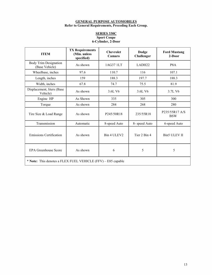
SERIES 330C Sport Coupe
6-Cylinder, 2-Door
ITEM TX Requirements
(Min. unless specified)
Chevrolet Camaro
Dodge Challenger
Ford Mustang 2-Door
Body Trim Designation (Base Vehicle) As shown 1AG37 1LT LADH22 P8A
Wheelbase, inches 97.6 110.7 116 107.1
Length, inches 159 188.3 197.7 188.3
Width, inches 67.8 74.7 75.5 81.9 Displacement, liters (Base
Vehicle) As shown 3.6L V6 3.6L V6 3.7L V6
Engine HP As Shown 335 305 300
Torque As shown 284 268 280
Tire Size & Load Range As shown P245/50R18 235/55R18 P235/55R17 A/S BSW
Transmission Automatic 8-speed Auto 8- speed Auto 6-speed Auto
Emissions Certification As shown Bin 4 ULEV2 Tier 2 Bin 4 Bin5 ULEV II
EPA Greenhouse Score As shown 6 5 5
* Note: This denotes a FLEX FUEL VEHICLE (FFV) – E85 capable

14
SERIES 350A
COMPACT HATCHBACK 4-CYLINDER, 5-DOOR
ITEM
TX Requirements (Min. unless
specified)
Chevrolet Sonic Ford Fiesta
Toyota Prius C
Body Trim Designation
(Base Vehicle) As shown 1JV48 1SD
LT P4E-SE
1201
Wheelbase,
inches 97.6 99.4 98 100.4
Length, inches 157.3 159 159.7 157.3
Width, inches 66.7 68.3 67.8 66.7
Displacement, liters (Base
Vehicle) As Shown 1.8L 1.6L Ti-VCT
1.5L/91
Engine HP As Shown 138 120 99
Torque As shown 125 112 82
Tire Size & Load
Range As shown P195/65R15 P185/60R15
P175/65R15
Transmission Automatic 6-speed Auto 6 Speed Auto Auto/Electric
Emissions
Certification As shown Bin 4 ULEV2
Tier 3 Bin 4 110
3.8
EPA Greenhouse
Score As shown 6 7 N/A
* Note: This denotes a FLEX FUEL VEHICLE (FFV) – E85 capable

15
SERIES 351A COMPACT SEDAN (5 PASSENGER)
4-CYLINDER, FRONT WHEEL DRIVE
ITEM
TX Requirements (Min. unless
specified)
Ford Focus FFV
Chevrolet Cruze
Nissan Sentra
Nissan Versa
Toyota Corolla
Body Trim Designation (Base Vehicle)
As shown SE 1BR69 1SB LS SV SV 1832 Base
Wheelbase, inches 102.4 104.3 106.3 106.3 102.4 106.3
Length, inches 173.5 178.7 183.7 182.1 175.4 183.1
Width, inches 66.7 71.8 70.5 69.3 66.7 69.9
Displacement, liters (Base Vehicle)
As shown 2.0L* FFV 1.4L 1.8L 1.6L 1.8L
Engine HP As shown 160 153 130 109 132 Torque As shown 146 177 128 107 128 Tire Size & Load Range As shown P195/65R15 P195/65R16 P205/55R16 P185/65R15 P195/65R15
Transmission Automatic 6 Speed Auto
6 Speed AutoOD
Xtronic CVT
Xtronic CVT
4 Speed Auto
Emissions Certification As shown Tier 3 Bin
110 Bin 4 ULEV
II
Tier2-Bin5 (EPA) /
LEV2-LEV (CARB)
Tier 2-Bin5 (EPA) / LEV2-ULEV Federal
Tier 2/Bin 5 ULEV II
EPA Greenhouse Score
As shown 7 7
TBD 7 TBD
Passenger Capacity 5 5 5
5 5 5

16
SERIES 357B
MIDSIZE HATCHBACK (5-7 Passengers) 6-CYLINDER, FRONT WHEELDRIVE,
5-DOOR
ITEM Texas Requirements (Min. unless specified) Dodge Journey* Ford Edge
Toyota Highlander
*Hybrid Body Trim Designation (Base Vehicle) As shown SXT K3G-SEL 6946
Wheelbase, inches 109.8 113.8 111.2 109.8 Length, inches 184.2 192.4 188.1 192.5 Width, inches 67.6 72.2 75.9 75.8 Displacement, liters (Base Vehicle) As shown 3.6L * E85 3.5L 3.5L
Engine HP 270 283 280 295 Torque 248 260 250 263 Tire Size & Load Range As shown P225/65R17 BSW
All-Season Touring
245/60R18 P245/65R R17
Transmission Automatic 6 Speed Auto 6 Speed Auto 8 speed OD
Emissions Certification As shown Bin 4+ULEV II Tier 2 Bin 5 ULEV II 6 LEV2 Bin 5
EPA Greenhouse Score As shown 5 5 N/A
Passenger Capacity 5 5 std 7 optional 5 5 std 7 optional
* Note: This denotes a FLEX FUEL VEHICLE (FFV) – E85 capable **Note: See Section A3.3. of this specification for limited usage on this series.

17
SERIES 358B
FULLSIZE HATCHBACK 6-CYLINDER, FRONT WHEEL DRIVE, 5-DOOR
(7 Passengers)
ITEM Texas Requirements
(Min. unless specified)
Chevrolet Traverse Ford Flex Toyota
Highlander
Dodge
Durango Body Trim Designation (Base Vehicle)
As Shown 1NB56 1LS/1FL SE 6948
Durango
SXT Wheelbase, inches 109.8 120.9 117.9 109.8 119.8
Length, inches 192.5 204.3 201.8 192.5 201.2
Width, inches 75.8 78.6 75.9 75.8 85.5 Displacement, liters (Base Vehicle)
As shown 3.6L 3.5L 3.5L
3.6L
Engine HP 281 305 287 295 295 Torque 254 260 254 263 290 Tire Size & Load Range P235/60R17 P255/65R18 P235/60R17 P245/65R17 P265/60R18
Transmission Automatic 9 Speed OD Auto 6 Speed Auto 6 Speed 8-Speed Auto
Emissions Certification Tier 2 Bin 5 Bin 4 ULEV 2 Tier 3 Bin 125 6 LEV 2 Bin 5 TBD
EPA Greenhouse Score
As Shown 5 4 N/A TBD
Passenger Capacity 7 8 7 8 7
* Note: This denotes a FLEX FUEL VEHICLE (FFV) – 85 capable **Note: See Section A3.3. of this specification for limited usage on this series.
18
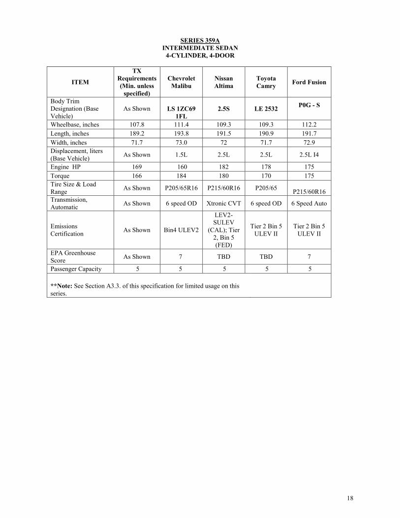
SERIES 359A
INTERMEDIATE SEDAN 4-CYLINDER, 4-DOOR
ITEM
TX Requirements (Min. unless
specified)
Chevrolet Malibu
Nissan Altima
Toyota Camry Ford Fusion
Body Trim Designation (Base Vehicle)
As Shown
LS 1ZC69 1FL
2.5S LE 2532 P0G - S
Wheelbase, inches 107.8 111.4 109.3 109.3 112.2 Length, inches 189.2 193.8 191.5 190.9 191.7 Width, inches 71.7 73.0 72 71.7 72.9 Displacement, liters (Base Vehicle) As Shown 1.5L 2.5L 2.5L 2.5L I4
Engine HP 169 160 182 178 175 Torque 166 184 180 170 175 Tire Size & Load Range As Shown P205/65R16 P215/60R16 P205/65
P215/60R16 Transmission, Automatic As Shown 6 speed OD Xtronic CVT 6 speed OD 6 Speed Auto
Emissions Certification As Shown Bin4 ULEV2
LEV2-SULEV
(CAL); Tier 2, Bin 5 (FED)
Tier 2 Bin 5 ULEV II
Tier 2 Bin 5 ULEV II
EPA Greenhouse Score As Shown 7 TBD TBD 7
Passenger Capacity 5 5 5 5 5 **Note: See Section A3.3. of this specification for limited usage on this series.

19
SERIES 360B
INTERMEDIATE SEDAN 6-CYLINDER, 4-DOOR
ITEM TX Requirements
(Min. unless specified)
Ford Fusion Nissan Altima
Toyota Camry
Chevrolet
Malibu Body Trim Designation (Base Vehicle)
As Shown SPORT S LE 2550
1ZD69 1LT
Wheelbase, inches 108.9 112.2 109.3 109.3 111.4
Length, inches 189.2 191.8 191.5 190.9 193.8 Width, inches 71.7 72.9 72 71.7 73.0 Displacement, liters (Base Vehicle) As Shown 2.7L GTDI
V6 3.5L V-6 3.5L-V6 2.0L SIDI VVT
Engine HP 240 325 270 268 250 Torque 248 380 251 248 260
Tire Size & Load Range As Shown
235/50R17
P235/45R18 P215/60R16
P225/55/R17
Transmission Automatic 6 Speed Auto Xtronic CVT 6 speed OD 8 speed Automatic
Emissions Certification As Shown Tier 3 Bin 70
LEV2-SULEV
(CAL); Tier 2, Bin 5 (FED)
Tier 2 Bin 5 ULEV II
Bin 4 ULEV II
EPA Greenhouse Score As Shown 4 TBD 6
TBD
Passenger Capacity As Shown 5 5 5 5
* Note: This denotes a FLEX FUEL VEHICLE (FFV) – E85 capable **Note: See Section A3.3. of this specification for limited usage on this series

20
SERIES 372B
FULL SIZE SEDAN 6-CYLINDER, 4-DOOR, FRONT WHEEL DRIVE
ITEM
TX Requirements (Min. unless
specified)
Chevrolet Impala*
FFV
Dodge Charger
FFV
Nissan Maxima
Ford Taurus*
FFV
Toyota Avalon XLE
Body Trim Designation (Base Vehicle)
As Shown
LS 1GX69 1FL
Charger SE S SE 3544
Wheelbase, inches 109.3 111.7 120.2 109.3 112.9 111 Length, inches 190.6 201.3 198.4 190.6 202.9 195.3 Width, inches 72.9 73.0 75.0 73.2 76.2 72.2
Displacement, liters (Base Vehicle) As Shown 3.6L V6
E85
3.6L with option of
FFV 3.5L V-6 3.5L*
FFV 3.5L V6
Engine HP 268 305 292 290 288 268 Torque 248 264 260 252 254 248 Tire Size & Load Range As Shown P235/50R18 P215/65/R1
7 P245/45R18
V 235/55R1
8 P215/55/R17
Transmission Automatic 6-Speed Auto OD
8 Speed Auto Xtronic CVT 6 Speed
Auto 6 Speed ECTI
Emissions Certification As Shown ULEV2 Bin
4
TBD LEV2-ULEV/Tier 2,
Bin 5
Tier 3 Bin125 ULEV2 Bin 4
EPA Greenhouse Score As Shown 5 TBD TBD 5 TBD
Passenger Capacity As Shown 5 5 5 5 5 * Note: This denotes a FLEX FUEL VEHICLE (FFV) – E85 capable **Note: See Section A3.3. of this specification for limited usage on this series.

21
SERIES 373B
FULL SIZE SEDAN 6-CYLINDER, UNI BODY
4-DOOR, REAR WHEEL OR ALL WHEEL DRIVE
ITEM TX Requirements
(Min. unless specified)
Dodge Charger REAR
WHEEL DRIVE*
Dodge Charger
All-Wheel Drive *
Ford Taurus All-Wheel
Drive* FFV
Chrysler 300
RWD
Body Trim Designation (Base Vehicle)
As Shown LDDM48-
CHARGER SE RWD
LDDM48-CHARGER SE AWD
P2H - SEL 300 Sedan
Limited
Wheelbase, inches 112.9 120.2 120.2 112.9 120.2 Length, inches 198.6 199.9 199.9 202.9 198.6 Width, inches 76.2 75 75 76.2 75 Displacement, liters (Base Vehicle) As shown 3.6 LV-6 FFV* 3.6 L V-6
FFV * 3.5L* FFV 3.6L V-6 FFV avail
Engine HP 288 292 292 288 292 Torque 254 260 260 254 260
Tire Size & Load Range As Shown
P215/65R17 BSW All-
Season Touring
P235/55R19 BSW All
Season Tires
235/55R18
P225/60R18
Transmission Automatic 8 speed Auto 8 Speed Auto 6 Speed Auto 8 Speed Auto Emissions Certification As Shown NAS BIN 4+
ULEV II NAS BIN 4+
ULEV II Tier 3 Bin125 TBD
EPA Greenhouse Score As Shown 5 6 5 TBD
Passenger Capacity As Shown 5 5 5 5 * Note: This denotes a FLEX FUEL VEHICLE (FFV) – E85 capable **Note: See Section A3.3. of this specification for limited usage on this series.

22
SERIES 374C
FULL SIZE SEDAN 6/8-CYLINDER, 4-DOOR, RWD
ITEM TX Requirements
(Min. unless specified)
Dodge Charger Rear-Wheel
Drive LDDP48 29Npkg
Body Trim Designation (Base Vehicle)
As Shown R/T RWD
Wheelbase, inches 120.2 120.2 Length, inches 199 199 Width, inches 75 75 Displacement, liters (Base Vehicle) As Shown 5.7 L V-8
Engine HP 370 370 Torque 395 395
Tire Size & Load Range As Shown
P235/55R19 BSW ALL SEASON TIRES (TPS)
Transmission Automatic 8-Spd Auto
Emissions Certification As Shown TBD
EPA Greenhouse Score As Shown TBD
Passenger Capacity 5 5 * Note: This denotes a FLEX FUEL VEHICLE (FFV) – E85 capable **Note: See Section A3.3. of this specification for limited usage on this series.
23
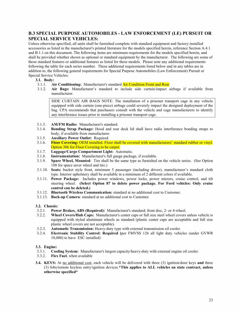
B.3 SPECIAL PURPOSE AUTOMOBILES - LAW ENFORCEMENT (LE) PURSUIT OR SPECIAL SERVICE VEHICLES: Unless otherwise specified, all units shall be furnished complete with standard equipment and factory-installed accessories as listed in the manufacturer's printed literature for the models specified herein, reference Section A.4.1. and B.1.1.on this document. The following items are minimum requirements for the models specified herein, and shall be provided whether shown as optional or standard equipment by the manufacturer. The following are some of those standard features or additional features as listed for these models. Please note any additional requirements following the table for each series number. These additional requirements listed below and in any tables are in addition to, the following general requirements for Special Purpose Automobiles (Law Enforcement) Pursuit or Special Service Vehicles:
3.1. Body: 3.1.1. Air Conditioning: Manufacturer's standard Air Condition Front and Rear 3.1.2. Air Bags: Manufacturer’s standard to include side curtain/impact airbags if available from
manufacturer.
SIDE CURTAIN AIR BAGS NOTE: The installation of a prisoner transport cage in any vehicle equipped with side curtain (one-piece) airbags could severely impact the designed deployment of the bag. CPA recommends that purchasers consult with the vehicle and cage manufacturers to identify any interference issues prior to installing a prisoner transport cage.
3.1.3. AM/FM Radio: Manufacturer's standard. 3.1.4. Bonding Strap Package: Hood and rear deck lid shall have radio interference bonding straps to
body, if available from manufacturer. 3.1.5. Auxiliary Power Outlet: Required 3.1.6. Floor Covering: OEM installed. Floor shall be covered with manufacturers’ standard rubber or vinyl.
Option 306 for Floor Covering to be carpet. 3.1.7. Luggage/Cargo Compartment Light: Automatic. 3.1.8. Instrumentation: Manufacturer's full gauge package, if available. 3.1.9. Spare Wheel, Mounted: Tire shall be the same type as furnished on the vehicle series. (See Option
108 for space saver wheel and tire.) 3.1.10. Seats: bucket style front, minimum 5 passenger (including driver), manufacturer’s standard cloth
type. Interior upholstery shall be available in a minimum of 2 different colors if available. 3.1.11. Power Package: Includes power windows, power locks, power mirrors, cruise control, and tilt
steering wheel. (Select Option 87 to delete power package. For Ford vehicles: Only cruise control can be deleted.)
3.1.12. Bluetooth Wireless Communication: standard at no additional cost to Customer. 3.1.13. Back-up Camera: standard at no additional cost to Customer.
3.2. Chassis: 3.2.1. Power Brakes, ABS (Required): Manufacturer's standard; front disc, 2- or 4-wheel. 3.2.2. Wheel Covers/Hub Caps: Manufacturer's center caps or full size steel wheel covers unless vehicle is
equipped with styled aluminum wheels as standard (plastic center caps are acceptable and full size plastic wheel covers are not acceptable).
3.2.3. Automatic Transmission: Heavy-duty type with external transmission oil cooler. 3.2.4. Electronic Stability Control: Required (per FMVSS 126 all light duty vehicles (under GVWR
10,000) to have ESC installed)
3.3. Engine: 3.3.1. Cooling System: Manufacturer's largest capacity/heavy-duty with external engine oil cooler. 3.3.2. Flex Fuel, when available
3.4. KEYS: At no additional cost, each vehicle will be delivered with three (3) ignition/door keys and three (3) fobs/remote keyless entry/ignition devices.*This applies to ALL vehicles on state contract, unless otherwise specified*

24
Note: the above are required options on the Series within this section. Ordering entities shall not pay additional cost for the requirement options. Charging a Customer for the above requirements may result in cancellation of award. Note: On specification tables, rim size means tire width, unless otherwise indicated.
SPECIAL PURPOSE AUTOMBILES – LAW ENFORCEMENT (LE) PURSUIT OR SPECIAL SERVICE VEHICLES
Refer to General Requirements, Preceding Each Group.
SERIES 460CLE--ALT
HYBRID GAS/ELECTRIC PURSUIT SEDAN *** 4-DOOR, FRONT WHEEL DRIVE, 4-CYLINDER
ITEM TX Requirements (Min. unless specified)
Ford Police Interceptor *E85
Body Trim Designation (Base Vehicle) As Shown P0A
Wheelbase, inches 110.0 112.2 Length (overall), inches 190.0 191.8 Width, inches 70.0 83.5 Displacement, liters (Base Vehicle) As Shown 2.0L I-4 Hybrid
Engine HP As Shown 188 Torque As Shown 129 Transmission Automatic eCVT Tire Size & Load Range As Shown P235/50R17 Rim size,( dia), inches As Shown 17” Steel Emissions Certification As Shown TBD EPA Greenhouse Score As Shown TBD ** Note: "LE" designation for Law Enforcement Pursuit or Special Purpose Vehicles only. *** Note: Refer to restrictions in Section 2158.003, Government Code, "for criminal law enforcement…"
Additional Equipment: The following equipment is required in addition to that required above:
a. Body:
1. Covering, Luggage Compartment: Luggage compartment floor shall be covered with a vinyl, rubber, or fiber type mat. (Option 306 for Floor Covering to be carpet.)
2. Speedometer: Calibrated to within plus or minus 2 MPH accuracy.
3. Trunk Release: If offered by manufacturers.
b. Chassis:
Suspension: Police pursuit rated suspension & components.

25
SERIES 462CLE Special Service Package Pick-Up Truck
8-CYLINDER, 4-DOOR, 2-WHEEL DRIVE
ITEM TX Requirements
(Min. unless specified)
RAM 1500 Crew Cab 4x4 SSV
F150 XL SSV
Chevrolet Silverado SSV
Body Trim Designation (Base Vehicle) As Shown DS6T98 XL CK15543 1WT
Wheelbase, inches 140 140.5 145.0 143.5 Payload Allowance, pounds (Approximate) 1,270 1,270 2,100 1,820
Length (overall), inches 229.0 229.0 231.9 230.0
Maximum Length at Floor 67 67.4 67.1 69.3
GVWR, pounds 6,900 6,900 TBD 7,200
Displacement, liters (Base Vehicle) As Shown 5.7L V8 Hemi
5.0L Ti-VCT V8 FFV 5.3L V8
Engine HP 355 395 385 355 Torque 380 410 387 383 Transmission As Shown 6-speed OD 6-speed 6 spd.
Tire Size & Load Range As Shown P265/70R17 BSW All-
Season P245/70R17 P255/70R17
Rim size,( dia), inches As Shown 7 17 17x8 Emissions Certification As Shown Bin 4 Bin 4 ULEV2 EPA Greenhouse Score As Shown 4 4
Additional Equipment: The following equipment is also required in addition to that required above:
a. Body: 1. Floor Covering, Cargo Compartment Luggage compartment floor shall be covered with a vinyl,
rubber, or fiber type mat. (Option 306 for Floor Covering to be carpet.) b. Chassis:
1. Suspension: Heavy-duty suspension and components. Note: Select option 52 for Four-Wheel Drive
26
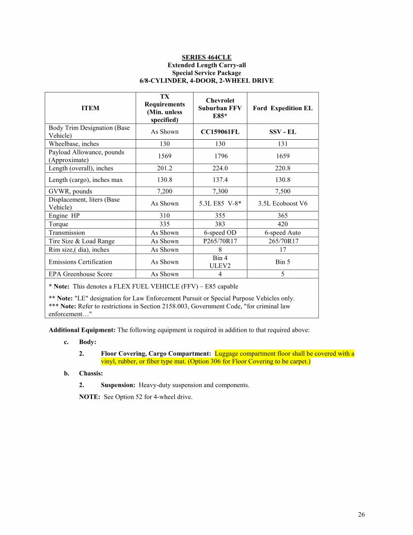
SERIES 464CLE Extended Length Carry-all
Special Service Package 6/8-CYLINDER, 4-DOOR, 2-WHEEL DRIVE
ITEM
TX Requirements (Min. unless
specified)
Chevrolet Suburban FFV
E85* Ford Expedition EL
Body Trim Designation (Base Vehicle) As Shown CC159061FL SSV - EL
Wheelbase, inches 130 130 131 Payload Allowance, pounds (Approximate) 1569 1796 1659
Length (overall), inches 201.2 224.0 220.8
Length (cargo), inches max 130.8 137.4 130.8
GVWR, pounds 7,200 7,300 7,500 Displacement, liters (Base Vehicle) As Shown 5.3L E85 V-8* 3.5L Ecoboost V6
Engine HP 310 355 365 Torque 335 383 420 Transmission As Shown 6-speed OD 6-speed Auto Tire Size & Load Range As Shown P265/70R17 265/70R17 Rim size,( dia), inches As Shown 8 17
Emissions Certification As Shown Bin 4 ULEV2 Bin 5
EPA Greenhouse Score As Shown 4 5
* Note: This denotes a FLEX FUEL VEHICLE (FFV) – E85 capable
** Note: "LE" designation for Law Enforcement Pursuit or Special Purpose Vehicles only. *** Note: Refer to restrictions in Section 2158.003, Government Code, "for criminal law enforcement…"
Additional Equipment: The following equipment is required in addition to that required above:
c. Body:
2. Floor Covering, Cargo Compartment: Luggage compartment floor shall be covered with a vinyl, rubber, or fiber type mat. (Option 306 for Floor Covering to be carpet.)
b. Chassis:
2. Suspension: Heavy-duty suspension and components.
NOTE: See Option 52 for 4-wheel drive.

27
SERIES 465CLE FULL SIZE UTILITY VEHICLE **
SPECIAL SERVICE PACKAGE 6/8-CYLINDER, HEAVY-DUTY, 4-DOOR, 2/4-WHEEL DRIVE
Additional Equipment: The following equipment is also required in addition to that required above:
a. Body:
Floor Covering, Cargo Compartment: Luggage compartment floor shall be covered with a vinyl, rubber, or fiber type mat. (Option 306 for Floor Covering to be carpet.)
ITEM
TX Requirements (Min. unless
specified)
Ford Expedition
Dodge Durango SSV FFV
(E85)*
Chevrolet Tahoe
SSV FFV *E85 4WD
Body Trim Designation (Base Vehicle)
As Shown SSV WDEE75 CK15706 5W4**
Wheelbase, inches 116 119 119 116 Payload Allowance, pounds (Approximate) 1,500 1698 1500 1794
Length (overall), inches 199.8 206.0 199.8 204
Length (cargo), inches max. 81.4 82.5 84.5 81.4
GVWR, pounds 7100 7260 7100 7300
Displacement, liters (Base Vehicle) As Shown 3.5L
Ecoboost V6
5.7L HEMI® V8/
or option 3.6L FFV
*E85
5.3L V-8 * FFV *E85
Engine HP 310 365 360/290 355 Torque 335 420 390/260 383
Transmission 6-Speed Automatic OD
6-Speed Auto
8-Speed Auto 845RE 6-Speed Auto
Tire Size & Load Range As Shown P265/70R17 P265/60R18
BSW P265/70R17
Rim size,( dia), inches As Shown 17 8 8 Emissions Certification As Shown Bin 5 NAS BIN 4+
ULEV II Bin ULEV2
EPA Greenhouse Score As Shown 3 3 4
* Note: This denotes a FLEX FUEL VEHICLE (FFV) – E85 capable ** Note: "LE" designation for Law Enforcement Pursuit or Special Purpose Vehicles only. *** Note: Refer to restrictions in Section 2158.003, Government Code, "for criminal law enforcement."

28
SERIES 466BLE FULL SIZE UTILITY VEHICLE PURSUIT**
6-CYLINDER, HEAVY-DUTY, 4-DOOR, ALL WHEEL DRIVE
ITEM TX Requirements (Min. unless specified)
Ford Utility Interceptor* FFV
Body Trim Designation (Base Vehicle) As Shown K8A
Wheelbase, inches 112.6 112.6 Payload Allowance, pounds (Approximate)
1610 1610
Length (overall), inches 196.8 197.1 Volume (Cargo Behind 2nd Row),cu-ft As Shown 48.1
Width, including mirrors inches 85.5 90.2 GVWR, pounds 6300 6342 Displacement, liters (Base Vehicle) As Shown 3.7L V6 Ti-VCT* FFV
Engine HP 290 304 Torque, ft-lb 260 279 Transmission Automatic 6-SPD AUTO
Tire Size & Load Range As Shown P245/55R18
Rim size,( dia), inches As Shown 18 Emissions Certification As Shown Bin 5 EPA Greenhouse Score As Shown 3 EPA Combined MPG As Shown 17 EPA Air Pollution Score As Shown 5 * Note: This denotes a FLEX FUEL VEHICLE (FFV) – E85 capable ** Note: "LE" designation for Law Enforcement Pursuit or Special Purpose Vehicles only. *** Note: Refer to restrictions in Section 2158.003, Government Code, "for criminal law enforcement…"
Additional Equipment
Heavy Duty Equipment - Alternator, Battery, Cooling System with engine oil cooler and transmission oil cooler, Powertrain Mounts, Brakes

29
SERIES 468CLE FULL SIZE UTILITY VEHICLE PURSUIT ***
8-CYLINDER, HEAVY-DUTY, 4-DOOR, 2-WHEEL DRIVE
ITEM TX Requirements (Min. unless specified)
Chevrolet Tahoe* PPV E85
Body Trim Designation (Base Vehicle) As Shown CC15706 9C1
Wheelbase, inches 116 116 Payload Allowance, pounds (Approximate) 1,588 1,590
Length (overall), inches 202 204 Length (cargo), inches 81.4 81.4 GVWR, pounds 6,800 6,800 Displacement, liters (Base Vehicle) As shown 5.3L V-8 * E85
Engine HP 320 355 Torque 335 383 Transmission Automatic A4OD 6-Speed Auto Tire Size & Load Range As Shown P265/60R17H Rim size,( dia), inches As Shown 8 Emissions Certification As Shown Bin ULEV2 EPA Greenhouse Score As Shown 4 * Note: This denotes a FLEX FUEL VEHICLE (FFV) – E85 capable ** Note: "LE" designation for Law Enforcement Pursuit or Special Purpose Vehicles only. *** Note: Refer to restrictions in Section 2158.003, Government Code, "for criminal law enforcement…"
Additional Equipment: The following equipment is also required in addition to that required above:
a. Body:
1. Floor Covering, Cargo Compartment: Luggage compartment floor shall be covered with a vinyl, rubber, or fiber type mat. (Option 306 for Floor Covering to be carpet.)
2. Speedometer: Certified, calibrated to within plus or minus 2 MPH accuracy.
b. Chassis:
1. Heavy Duty, Locking Differential.

30
SERIES 471BLE FULL SIZE PURSUIT SEDAN ***
4-DOOR, FRONT WHEEL DRIVE, 6-CYLINDER
SPECIAL NOTE 1: General Motors may require pilot model inspection on special order two-tone paints Additional Equipment: The following equipment is required in addition to that required above:
b. Body:
4. Covering, Luggage Compartment: Luggage compartment floor shall be covered with a vinyl, rubber, or fiber type mat. (Option 306 for Floor Covering to be carpet.)
5. Speedometer: Certified, calibrated to within plus or minus 2 MPH accuracy.
6. Trunk Release: To be ignition fed, if offered by manufacturers.
b. Chassis:
Suspension: Police pursuit rated suspension & components.
ITEM TX Requirements (Min. unless specified)
Ford Police Interceptor *E85
Body Trim Designation (Base Vehicle) As Shown P2L
Wheelbase, inches 110.5 112.9 Length (overall), inches 200.4 202.9 Width, inches 72.9 85.7 Displacement, liters (Base Vehicle) As Shown 3.5L TiVCT V6 FFV*
Engine HP 288 288 Torque 254 254 Transmission Automatic 6 Speed Automatic Tire Size & Load Range As Shown 245/55R18 A/S BSW Rim size,( dia), inches As Shown 18 Emissions Certification As Shown Tier 3 Bin 125 EPA Greenhouse Score As Shown 5 * Note: This denotes a FLEX FUEL VEHICLE (FFV) – E85 capable ** Note: "LE" designation for Law Enforcement Pursuit or Special Purpose Vehicles only. *** Note: Refer to restrictions in Section 2158.003, Government Code, "for criminal law enforcement…"

31
SERIES 474BLE FULL SIZE SEDAN ***
PURSUIT 4-DOOR, UNI BODY, REAR WHEEL DRIVE, 6-CYLINDER
ITEM TX Min. Requirements
Dodge Charger Police Package FFV
E85** Body Trim Designation (Base Vehicle) As Shown LDDE48-CHARGER
POLICE RWD Wheelbase, inches 118.5 120.2 Length (overall), inches 199.9 199.9 Width, inches 74.75 75 Displacement, liters (Base Vehicle) As shown 3.6 V6 FFV *
Engine HP 292 292 Torque 260 260 Transmission As Shown 5-Speed Auto
Tire Size & Load Range As Shown P225/60VR18 BSW V-rated
Rim size,( dia), inches As Shown 18X7.5 STEEL WHEELS
Emissions Certification As Shown NAS BIN 4+ ULEV II EPA Greenhouse Score As Shown 5 * Note: This denotes a FLEX FUEL VEHICLE (FFV) – E85 is available as a no charger item please specify at time of order! ** Note: "LE" designation for Law Enforcement Pursuit or Special Purpose Vehicles only. *** Note: Refer to restrictions in Section 2158.003, Government Code, "for criminal law enforcement…"
SPECIAL NOTE : The Dodge Charger is also available with 5.7L Hemi V8, 370hp and 398 torque. (See 476CLE
Series). Additional Equipment: The following equipment is required in addition to that required above:
a. Body:
1. Covering, Luggage Compartment: Luggage compartment floor shall be covered with a vinyl, rubber, or fiber type mat. (Option 306 for Floor Covering to be carpet.)
2. Speedometer: Certified, calibrated to within plus or minus 2 MPH accuracy.
3. Trunk Release: To be ignition fed.
b. Chassis:
1. Suspension: Police pursuit rated suspension & components.
Additional Options: (See Option listing shown under Series 476CLE table)

32
SERIES 475BLE FULL SIZE SEDAN PURSUIT ***
4-DOOR, ALL WHEEL DRIVE, 6-CYLINDER
ITEM TX Requirements (Min. unless specified)
Ford Police Interceptor FFV E85
**
Body Trim Designation (Base Vehicle) As Shown P2M
Wheelbase, inches 112.9 112.9 Payload Allowance, pounds (Approximate) 1392 1392 Length (overall), inches 202.9 202.9 Width, including mirrors inches 85.7 85.7 GVWR, pounds 5700 5700 Displacement, liters (Base Vehicle) As Shown 3.7L V6 Ti-VCT* FFV Engine HP 288 305 Torque, ft-lb 254 279 Transmission Automatic 6-Speed Auto
Tire Size & Load Range As Shown P245/55R18 A/S BSW
Rim size,( dia), inches As Shown 8 Emissions Certification As Shown Tier 2 Bin 5 EPA Greenhouse Score As Shown 5 EPA Combined MPG As Shown 21 EPA Air Pollution Score As Shown TBD * Note: This denotes a FLEX FUEL VEHICLE (FFV) – E85 capable ** Note: "LE" designation for Law Enforcement Pursuit or Special Purpose Vehicles only. *** Note: Refer to restrictions in Section 2158.003, Government Code, "for criminal law enforcement…"
Additional Equipment
Heavy Duty Equipment - Alternator, Battery, Cooling System with engine oil cooler and transmission oil cooler, Powertrain Mounts, Brakes Luggage compartment floor shall be covered with a vinyl, rubber, or fiber type mat. (Option 306 for Floor Covering to be carpet.)

33
SERIES 476CLE FULL SIZE PURSUIT SEDAN ***
4-DOOR, REAR WHEEL DRIVE, 8-CYLINDER UNIBODY
ITEM TX Requirements (Min. unless specified) Dodge Charger
Body Trim Designation (Base Vehicle) As Shown LDDE48-CHARGER POLICE
RWD Wheelbase, inches 120.2 120.2 Length (overall), inches 199.9 199.9 Width, inches 75 75 Displacement, liters (Base Vehicle) As shown 5.7L V-8
Engine HP 370 370 Torque 395 395 Transmission As Shown 5-Speed Auto
Tire Size & Load Range As Shown P225/60VR18 BSW V-rated
Rim size,( dia), inches As Shown 18x7.5 STEEL WHEELS Emissions Certification As Shown NAS BIN 4 + ULEV II + EPA Greenhouse Score As Shown 4 * Note: This denotes a FLEX FUEL VEHICLE (FFV) – E85 capable ** Note: "LE" designation for Law Enforcement Pursuit or Special Purpose Vehicles only. *** Note: Refer to restrictions in Section 2158.003, Government Code, "for criminal law enforcement…"
Additional Equipment: The following equipment is also required in addition to that required above:
a. Body:
1. Covering, Luggage Compartment: Luggage compartment floor shall be covered with a vinyl, rubber, or fiber type mat. (Option 306 for Floor Covering to be carpet.)
2. Speedometer: Certified, calibrated to within plus or minus 2 MPH accuracy. 3. Trunk Release: To be ignition fed.
b. Chassis: 1. Suspension: Police pursuit rated suspension and components

34
SERIES 478CLE FULL SIZE PURSUIT SEDAN
4-DOOR, ALL WHEEL DRIVE, 8-CYLINDER UNIBODY
ITEM TX Requirements (Min. unless specified)
Dodge Charger Police AWD
Body Trim Designation (Base Vehicle) As Shown LDEE48
Wheelbase, inches 120.2 120.2 Length (overall), inches 199.9 199.9 Width, inches 75 75 Displacement, liters (Base Vehicle) As shown 5.7L V-8
Engine HP 370 370 Torque 395 395 Transmission As Shown 5-Speed Auto
Tire Size & Load Range As Shown P225/60VR18 BSW V-rated
Rim size,( dia), inches As Shown 18x7.5 STEEL WHEELS
Emissions Certification As Shown NAS BIN 4 + ULEV II +
EPA Greenhouse Score As Shown 4 * Note: This denotes a FLEX FUEL VEHICLE (FFV) – E85 capable ** Note: "LE" designation for Law Enforcement Pursuit or Special Purpose Vehicles only. *** Note: Refer to restrictions in Section 2158.003, Government Code, "for criminal law enforcement…"
Additional Equipment: The following equipment is required in addition to that required above:
a. Body:
1. Covering, Luggage Compartment: Luggage compartment floor shall be covered with a vinyl, rubber, or fiber type mat. (Option 306 for Floor Covering to be carpet.)
2. Speedometer: Certified, calibrated to within plus or minus 2 MPH accuracy. 3. Trunk Release: To be ignition fed.
b. Chassis: 1. Suspension: Police pursuit rated suspension and components

35
B.4. UTILITY VEHICLES (CARRYALLS, 4-WHEEL DRIVE UTILITY, AND CARGO VANS): Unless otherwise specified, all units shall be furnished complete with standard equipment and factory- installed accessories as listed in the manufacturer's printed literature for the models specified herein (See Section A.4.1. and Section B.1.1.). The following items are minimum requirements for the models specified herein, and shall be provided whether shown as optional or standard equipment by the manufacturer. The following are some of those standard features or additional features as listed for these models. Please note any additional requirements following the table for each series number. These additional requirements listed below any table are in addition to, the following general requirements for Utility Vehicles:
4.1. Body:
4.1.1. Air Bags: Manufacturer’s standard to include side curtain/impact airbags if available from manufacturer.
4.1.2. Air Conditioning: Manufacturer's standard. 4.1.3. Arm Rests: Left door only. Both right and left arm rests are required if right front seat is provided. 4.1.4. AM/FM Radio: Manufacturer's standard. 4.1.5. Auxiliary Power Outlet: 12 volt. 4.1.6. Heater and Defroster: See Accessory Specifications. 4.1.7. Power Package: Includes power windows, power locks, power mirrors, cruise control, and tilt steering
wheel. (Select Option 87 to delete power package.) 4.1.8. Seat, Cloth: Front seats split bench 40/60, 40/20/40, or buckets. (Bench not acceptable) (Option No.
258 is for vinyl seats.) 4.1.9. Sun Visor: Driver's side only. Dual sun visors are required if right front seat is provided. 4.1.10. Windshield Wipers: Dual electric 2-speed type with intermittent feature windshield washers. 4.1.11. Window Tint: OEM Standard Tint. Tinting shall meet Texas DPS regulations. 4.1.12. Bluetooth Wireless Communication: OEM standard at no additional cost to Customer. 4.1.13. Back-up Camera: OEM standard no additional cost to Customer
4.2. Chassis:
4.2.1.Power Brakes, ABS, required: Manufacturer's standard; front disc, 2- or 4-wheel. 4.2.2.Automatic Transmission 4.2.3.Bumpers: Manufacturer’s standard front and rear bumper 4.2.3.Ground Ratings: As required for the GVWR certified. 4.2.4.Jack, Handle, and Lug Wrench 4.2.5.Shock Absorbers: Front and rear. Manufacturer’s heaviest duty shocks without increase in vehicle trim
level. 4.2.6.Spare Wheel and Tire (mounted on carrier): Manufacturer's standard. Must be OEM BRAND
NAME, TYPE AND SIZE OF TIRE to those on the vehicle, where available. 4.2.7.Tires (including spare): Steel belted radial type tubeless tires. 4.2.8. Electronic Stability Control: Required (per FMVSS 126 all light duty vehicles (under GVWR
10,000) to have ESC installed. 4.2.9. Power Steering: Manufacturer’s standard 4.2.10. Flex Fuel, when available
4.3. Cargo Weight:
4.3.1. Approximate Payload Allowance: (See definition in Section A.2)
4.4. KEYS: At no additional cost, each vehicle will be delivered with three (3) ignition/door keys and three (3) fobs/remote keyless entry/ignition devices.*This applies to ALL vehicles on state contract, unless otherwise specified*

36
Note: the above are required options on the Series within this section. Ordering entities shall not pay additional cost for the requirement options. Charging a Customer for the above requirements may result in cancellation of award. Note: On specification tables, rim size means tire width, unless otherwise indicated.
UTILITY VEHICLES (CARRYALLS, 4-WHEEL DRIVE UTILITY, AND CARGO VANS) Refer to General Requirements, Preceding Each Group.
SERIES 650C
CARRYALL GASOLINE, 1/2 TON, 2 WHEEL DRIVE V-8 OR V-6 ACCEPTABLE
ITEM TX Requirements
(Min. unless specified)
FORD Expedition
Chevrolet Suburban* FFV E85
GMC Yukon XL
FFV *E85 Body Trim Designation (Base Vehicle)
As Shown K1F - EL CC15906 1FL
TC15906 3SA
Wheelbase, inches 130 131 130 130 Payload Allowance, max pounds (Approximate)
1538 1690 1796 1633
Length (overall), inches 220.8 220.8 224 224
GVWR, pounds 7200 7,540 7300 7300 Displacement, liters (Base Vehicle) As shown 3.5L V6
Ecoboost 5.3L V-8* E85 5.3L V-8* E85
Engine HP 320 365 355 355 Torque 335 420 383 383 Transmission Automatic 6 Speed Auto 6 speed Auto 6 speed Auto Tire Size & Load Range P265/70R17 265/70R17
P265/70R17 P265/65R18
Rim size,( dia), inches 7 7.5 7 7 Emissions Certification As Shown Bin 5 Bin 4
ULEV2 Bin 4
ULEV2 EPA Greenhouse Score As Shown 3 4 4
* Note: This denotes a FLEX FUEL VEHICLE (FFV) – E85 capable ** Note: See Section A.3.3 of this specification for the limited use of this vehicle.
Additional Equipment: The following equipment is required in addition to that required above:
a. Body: 1. Seating Capacity: Minimum 5 passengers including the driver. See Option No. 99 to increase
seating capacity. 2. Headliner: Full length, factory installed where available. 3. Side Panels, Interior: Option of rigid material with a durable finish (such as plastic) or carpet
installed on all walls, wheel wells, and doors, factory installed, when available. 4. Cab and Cargo Area Insulation: Factory installed, when available.

37
5. Floor Covering, Cargo Compartment: Cargo compartment floor shall be covered with manufacturers’ standard carpet or rubber floor covering. (Requirement will be indicated prior to ordering vehicle)
NOTE: Unless Option No. 99 is requested, this vehicle will be provided with a front and middle seat only.
SERIES 658A CARGO VAN, 4-CYLINDER
4-DOOR, FRONT WHEEL DRIVE
ITEM TX Requirements (Min. unless specified)
Ford Transit Connect
Nissan NV200
Ram ProMaster
City
Chevrolet City Express
Body Trim Designation (Base Vehicle) As Shown Cargo Van
XL Cargo Van
SV
VMDL51
Cargo VAN 15S60 1LS
Wheelbase, inches 114.6 120.6 115.2 122- 115.2 Payload Allowance, max pounds (Approximate) 1500 1620
1,500 (est) 1883 1500
Length (overall), inches 176 189.7 186.3 187.5 186.3
Length(Cargo), inches As Shown 87.3
122.7
87.2
82.8
GVWR, pounds 4718 5270
4718
5380
4,751
Displacement, liters (Base Vehicle) As shown 2.5L 2.0L
2.4L 24- VALVE DOHC I-4
2.0
Engine HP 131 169 140 178 131
Torque 128 171 147 174 139
Transmission Automatic 6 Speed Auto Xtronic CVT 9 speed auto variable automatic
Tire Size & Load Range As Shown 215/55R16 185/60R15 215/55R16 185/60R15
Rim size,( dia), inches As Shown 6.5
5.5
6.5
5.5
Emissions Certification As Shown Tier 3 Bin 125 ULEV II
50S: LEV2-LEV (Cal), Tier2(B5)
(Fed); CAL: PZEV
50S: LEV2-LEV (Cal), Tier2(B5) (Fed); CAL: PZEV
EPA Greenhouse Score As Shown 5 TBD 6 * Note: This denotes a FLEX FUEL VEHICLE (FFV) – E85 capable ** Note: See Section A.3.3 of this specification for the limited use of this vehicle.

38
SERIES 659A UTILITY VEHICLE, COMPACT
4-CYL, 4-DOOR, LIGHT DUTY, FWD
ITEM
TX Requirements (Min. unless
specified)
Nissan Rogue
Ford Escape
Chevrolet Equinox
Toyota Rav4
Jeep
Compass
Body Trim Designation
(Base Vehicle) As Shown S S
1XP261LS 4430
Sport
Wheelbase, inches 103.7 105.9 105.9
107 104.7 103.7
Length (overall),
inches 173.6 183.3/1,047 178.1
183 183.5 173.0
Length (Cargo), inches
As Shown 70.9 68.0 56.4
73.4 2nd row –
38.4
59.8
GVWR, pounds 3515 4339 3515 curb
weight
4464 4525 4400
Displacement, liters (Base
Vehicle) As Shown 2.5L I-4 2.5L I-4
1.5L Turbo
DOHC, VVT
2.5L DOHC
2.4L
Engine HP 158 175 168 170 176 172
Torque 141 170 170 203 172 165
Transmission Automatic CVT 6-speed auto
6 Speed Auto OD
6 speed ECTI
6 Spd Auto
Tire Size & Load Range As Shown P215/70R16 P235/55R1
7 P225/65R17 P225/65R17 215/65R16
Rim size,( dia), inches As Shown 6.5 6 7 6.5 TBD
Emissions Certification As Shown Tier 2, Bin 5 Tier 3, Bin
125 Bin 4
ULEV2 ULEV II TBD
EPA Greenhouse
Score As Shown TBD 5 6 TBD
TBD

39
SERIES 661B
UTILITY VEHICLE, SMALL SIZE 6-CYLINDER, LIGHT-DUTY, 4-DOOR, 2 RWD OR 4-WHEEL DRIVE
ITEM TX Requirements
(Min. unless specified)
Nissan Xterra Jeep Wrangler Jeep®
Cherokee FFV
Ford Explorer
Chevrolet Traverse
Body Trim Designation (Base Vehicle)
As Shown X Unlimited Sport (4 x 4) Sport
INV56LS
Wheelbase, inches 106.3 106.3 116 106.3 112.8 120.9
Payload Allowance, max lbs (Approximate) 1,000
4x2-1058 4x4 – 1045
Est. 1099 1000
1,500
1,798
Length (overall), inches 178.7 178.7 184.8 182
198.3 204.3
Length(Cargo), inches 54.9 65.7 31.5
70.6 Rear seat folded
54.9
81.7 98.5 behind
1st row
GVWR, pounds 5201 5201 (4x2) 5400 5500 (4x4) 6160 6160 Displacement, liters (Base Vehicle) As Shown 4.0L V6 3.6L V6 3.2L V6 3.5L TiVCT
V6 3.6L V-6
Engine HP 261 261 285 271 290 305 Torque 239 281 260 239 255 260
Transmission Automatic 5-Speed Automatic
5-speed Automatic
9-speed Automatic
6-speed Automatic
9-speed Automatic
Tire Size & Load Range As Shown P265/70R16 P225/75R16
On/Off-Road 225/65R17 BSW All
P245/60R18 255/65R18
Rim size,( dia), inches As Shown 7 7.0 7 8 8 Emissions Certification As Shown 50 State ULEV NAS BIN 4+
ULEV II + TBD Bin 5 Bin 4 ULEV 2
EPA Greenhouse Score As Shown TBD 4 TBD 4 5
* Note: This denotes a FLEX FUEL VEHICLE (FFV) – E85 capable
Additional Equipment: The following equipment is required in addition to that required above:
a. Body:
1. Seating Capacity: minimum 4 passengers including driver

40
SERIES 662B
UTILITY VEHICLE, MID SIZE, 6-CYLINDER, LIGHT-DUTY REAR WHEEL DRIVE, 4-DOOR, 2-WHEEL DRIVE
ITEM
TX Requirements (Min. unless
specified)
Grand Cherokee Nissan Pathfinder
Toyota 4 Runner
Explorer
Chev Trav
Body Trim Designation (Base Vehicle) As Shown Laredo S 8642 BASE AW
INV Wheelbase, inches 109.8 114.8 114.2 109.8 112.8 12 Payload Allowance, max pounds (Approximate) 1500 2030 1,500 (est) 1700
1500
1,7
Length (overall), inches 189.2 189.9 197.2 190.2 198.3
20
Length(Cargo), inches 68.7 68.7 79.8 89.7 81.7 98.5 be ro
GVWR, pounds 5912.7 6500 5912.7 6100 6160 61
Displacement, liters (Base Vehicle) As Shown
V-6 *FFV /5.7L V8 Hemi Option
Available with a 3.0L EcoDiesel
engine
3.5L V-6 4.0L V6
3.5L TiVCT V6
3.6L
Engine HP 260 290V6/360 V8/240V6 EcoDiesel
260 270
290 30
Torque 240 260V6/390 V8/420V6 EcoDiesel
240 278
255 2
Transmission Automatic 8 speed auto CVT 5 speed Auto 6 speed Auto
9-sp Auto
Tire Size & Load Range As Shown P245/70R17 BSW On/Off Road Tires P235/55R20 P265/70R/17 P245/60R18 255/6
Rim size,( dia), inches As Shown 8 7.5 7 8
Emissions Certification As Shown NAA/BIN 5 LEV2-ULEV/ Tier2‐Bin5 ULEV 2 Bin 5 Bin 5 Bin 4 U
EPA Greenhouse Score As Shown V6 5 V8 4 TBD 3 4
* Note: This denotes a FLEX FUEL VEHICLE (FFV) – E85 capable ** Note: See Section A.3.3 of this specification for the limited use of this vehicle. *** Note: Cargo length behind 2nd row of seats
Additional Equipment: The following equipment is required in addition to that required above. Body:
1. Seating Capacity: Minimum 5 passengers including driver.

41
SERIES 663B UTILITY VEHICLE, MID SIZE, 6-CYLINDER, LIGHT-DUTY
FRONT WHEEL DRIVE, 4-DOOR, 2-WHEEL DRIVE
ITEM TX Requirements
(Min. unless specified)
Dodge Journey
FFV
Ford Explorer
Toyota Highlander
Chevrolet Traverse
Body Trim Designation (Base Vehicle)
As Shown SXT K7B 6946 1NB561LS (1FL)*
Wheelbase, inches 112.5 113.8 112.8 109.8 121 Payload Allowance, max pounds (Approximate)
1,151 1203 TBD 1,370 1,798
Length (overall), inches 188.4 192.4 198.3 192.5
204.3 Length(Cargo), inches As Shown 67.6 TBD 83.7 98
GVWR, pounds 5100 5100 TBD 5840 6160 Displacement, liters (Base Vehicle) As Shown 3.6 L V6
FFV E85 3.5L TiVCT
V6 3.5L V6 3.6L V6
Engine HP 270 283 290 295 305
Torque 248 260 255 263 260
Transmission Automatic 6-Speed Auto 6 speed auto 5-speed Auto OD 9 Speed
Tire Size & Load Range As Shown
P225/65R17 BSW All-
Season Touring
P245/60R18 P245/65R17 P255/65R18
Rim size,( dia), inches As Shown 6.5 TBD 7.5 TBD
Emissions Certification As Shown NAS BIN 4+
ULEV II + Tier 2
ULEV Bin 5 ULEV 2 Bin 5 Bin 4 UVLEV 2
EPA Greenhouse Score As Shown 5 TBD 4 5
* Note: This denotes a FLEX FUEL VEHICLE (FFV) – E85 capable ** Note: See Section A.3.3 of this specification for the limited use of this vehicle. *** Note: Cargo length behind 2nd row of seats
Additional Equipment: The following equipment is required in addition to that required above:
a. Body:
1. Seating Capacity: Minimum 5 passengers including driver.

42
SERIES 665C UTILITY VEHICLE, FULL SIZE
6/8-CYLINDER, REAR WHEEL DRIVE, 4-DOOR, 2-WHEEL DRIVE
ITEM
TX Requirements (Min. unless
specified)
Chevrolet Tahoe*
Ford Expedition
Dodge Durango
Nissan Armada
GMC Yukon*
Toyota Sequoia
Body Trim Designation (Base Vehicle)
As Shown CC15706 1FL XL WDDE75 SV TC15706
1SA 7917
Wheelbase, inches 116 116 119 119.8 123.2 116 122 Payload Allowance, max pounds (Approximate)
1370 1720 1630 1500 1,680
1720 1370
Length (overall), inches 199.8 204 206.0 199.8 207.7 204 205.1
Length(Cargo) inches** As Shown
51.7 44.4 52.6 61.4 51.4 TBD
GVWR, pounds 7,100 7,100 7,260 7100 7,100 7,100 7,100
Displacement, liters As Shown 5.3L V-8 *
E85 3.5L V6 Ecoboost
5.7L V8 HEMI MDS
VVT/optional 3.6L V6 24V VVT Engine
5.6L V-8 FFV E85*
5.3L V-8 * E85 5.7L V-8
Engine HP 310 355 365 360/290 317 355 381 Torque 335 383 420 390/260 385 383 401
Transmission Automatic 6 Speed Auto
6 Speed Auto
8-Spd Auto 845RE
5 speed Auto OD
6 Speed Auto
6 speed ECTI
Tire Size & Load Range As Shown P265/70R17 P265/70R17
P265/60R18 BSW On/Off Road Tires
P275/60R20 P265/70R17 P215/55R17
Rim size, dia. in. As Shown 17x8 7.5 8 8 17x8 8
Emissions Certification As Shown Bin 4
ULEV2 Bin 5 NAS BIN 4+ ULEV II +
50 state: LEV2-LEV
(Cal), Tier2(B5)
(Fed)
Bin 4 ULEV2 ULEV II
EPA Greenhouse Score As Shown 4 3 3 TBD 4 TBD
* Note: This denotes a FLEX FUEL VEHICLE (FFV) – E85 capable ** Note: See Section A.3.3 of this specification for the limited use of this vehicle. *** Note: Cargo length behind 2nd row of seats
Additional Equipment: The following equipment is required in addition to that required above:
a. Body: 1. Seating Capacity: 4 passenger, including driver.
2. Air Conditioning: Front and Rear.

43
SERIES 668C MINI-CARGO VAN 2 WHEEL, 6 OR 8-CYL, 2WD
ITEM TX Requirements (Min. unless specified) Ram Promaster VPG MV-1
Accessible Van
Ford
Transit Connect
ADA
Body Trim Designation (Base Vehicle) As Shown VF1L11 DX XL
Wheelbase, inches 118 118 122 120.6
Payload Allowance, max pounds (Approximate) 1500 3990 1500 1620
Length (overall), inches 189 195.4 205 189.7
Length(Cargo), inches 99 105 115 169
GVWR, pounds 5,380 8,550 6,600 5,380
Displacement, liters (Base Vehicle) As Shown 3.6L V-6 4.6L V8 2.5L
Engine HP 169 280 248 169
Torque 171 260 294 171
Transmission Automatic 6-Speed Auto 4-Speed with O/D 6-Speed Auto
Tire Size & Load Range As Shown 225/775R16 All
Season
P235/65/R17XL All Season 215/55R16
Rim size,(dia), inches As Shown 16x6.0 Steel
Wheels
17x6.5 STEEL WHEELS 6.5
Emissions Certification As Shown TBD Tier 2, Bin 4 Tier 2 Bin 4
ULEVII
EPA Greenhouse Score As Shown TBD TBD 6
Additional Equipment: The following equipment is also required in addition to that required above:
a. Body:
1. Cargo Door: Manufacturer's standard configuration.
2. Seating Capacity: Driver's and Front passenger
3. Full Length Headliner, if available

44
SERIES 670B 1/2 TON, FULL SIZE CARGO VAN
6-CYLINDER, 2-WHEEL, RWD/FWD
Additional Equipment: The following equipment is also required in addition to that required above:
a. Body: 1. Cargo Door:
a. Right side, Swing-Out Panel (See Option No. 201 for Sliding Side Door or Option No. 202 for Swing-Out Doors on driver’s side).
b. Left Side, with RH Swing-Out Doors (See Option No. 203) 2. Full Length Headliner, if available. 3. Seating Capacity: Driver's and Front passenger
ITEM TX Requirements
(Min. unless specified)
RAM
ProMaster FORD TRANSIT 150 FFV
Body Trim Designation (Base Vehicle) As Shown 1500 CARGO VAN
LOW ROOF VF1L12 E1Y
Wheelbase, inches 130 136 130 Payload Allowance, max pounds (Approximate)
2,360
3852 3675
Length (overall), inches 213 213 219.9
Length(Cargo), inches 123 123 126 GVWR, pounds 7,300 8,550 8600
Displacement, liters (Base Vehicle) As Shown
V6/ Optional 3.0L EcoDiesel I4
3.7L V6
Engine HP 195 280 /174 275 Torque 250 260 /295 260
Transmission Automatic 6 speed Auto/Manual 6-speed clutchless 6 speed Auto
Tire Size & Load Range As Shown 225/75R16C BSW
ALL SEASON TIRES (TU4)
235/65/16
Rim size,( dia), inches As Shown 16x6.0 STEEL WHEELS (WCS) 16x6.0 STEEL WHEELS (WCS)
Emissions Certification As Shown N/A N/A
EPA Greenhouse Score As Shown TBD
TBD
* Note: This denotes a FLEX FUEL VEHICLE (FFV) – E85 capable

45
SERIES 670C 1/2 TON FULL SIZE CARGO VAN
STANDARD GLASS: WINDSHIELD, LEFT AND RIGHT FRONT DOORS 8-CYLINDER
ITEM TX Requirements
(Min. unless specified)
Ford Transit 150 *FFV E85 Ram ProMaster FWD
Body Trim Designation (Base Vehicle)
As Shown E1Z 1500 CARGO VAN LOW ROOF VF1L12
Wheelbase, inches 130 130 136 Payload Allowance, max pounds (Approx.)
2,342 3600 3,852
Length (overall), in. 213 219.9 213.0
Length(Cargo), in. 121.4 126 123.0 GVWR, pounds 7,300 8600 8,550 Displacement, liters (Base Vehicle)
As Shown 3.7L V6 3.6 L V6
Engine HP 225 270 280/174 Torque 260 260 260/295
Transmission Automatic 6 speed auto 6 speed Auto6 speed/Manual 6-speed clutchless
Tire Size & Load Range As Shown 235/65R16 225/75R16C BSW ALL
SEASON TIRES
Rim size,( dia), in As Shown 16 16X6.0 STEEL WHEELS (WCS)
Emissions Certification As Shown TBD N/A
EPA Greenhouse Score As Shown TBD TBD
* Note: This denotes a FLEX FUEL VEHICLE (FFV) – E85 capable Additional Equipment: The following equipment is also required in addition to that required above:
a. Body: 1. Cargo Door: Right side, Swing-Out Panel (See Option No. 201 for Sliding Side Door) 2. Full Length Headliner, if available 3. Seating Capacity: Driver's and Front passenger

46
SERIES 680C 3/4 TON FULL SIZE CARGO VAN
STANDARD GLASS: WINDSHIELD, LEFT AND RIGHT FRONT DOORS 6/ 8-CYLINDER
ITEM
TX Requirements (Min. unless
specified)
Chevrolet CG23405/
GMC TG23405
Transit 250 *FFV E85
Nissan NV2500
RAM PROMASTER CARGO VAN
Body Trim Designation (Base Vehicle)
As Shown 1WT R1Z S VF2L13 High Roof
Wheelbase, inches 130 135 130 146.1 136 Payload Allowance, max pounds (Approximate)
3,287 3,287 4,000
3086.5
4,113
Length (overall), inches 213 224.1 219.9 240.6 213
Length(Cargo), inches 122.4 124.6 126 234.1 123
GVWR, pounds 8,600 8,696 9,000 9100 8,900 Displacement, liters (Base Vehicle) As Shown 4.3L V-6 3.5L V6
FFV E85 5.6L 3.6 L V6/ Optional 3.0L EcoDiesel I4
Engine HP 225 280 270 317 280/174 Torque 250 295 260 385 260/295
Transmission Automatic 8 speed auto 6 speed auto 5 speed AUTO
6 speed Auto/Manual 6-speed clutchless
Auto
Tire Size & Load Range As Shown LT245/75R16E 235/65R16 LT245/70/R17
225/75R16C BSW ALL SEASON TIRES (TU4)
Rim size,( dia), inches As Shown 16 X 6.5 16 7.5 16X6.0
Emissions Certification As Shown Bin 8 MDV ULEV TBD
HDV1(Fed)/LEVII-ULEV
MDV6(Cal) N/A
EPA Greenhouse Score As Shown 1 TBD TBD TBD
* Note: This denotes a FLEX FUEL VEHICLE (FFV) – E85 capable
Additional Equipment: The following equipment is required in addition to that required above:
a. Body:
1. Cargo Door: Right side, Swing-Out Panel (See Option 201 for Sliding Side Door). 2. Full Length Headliner, if available 3. Seating Capacity: Driver's and Front passenger
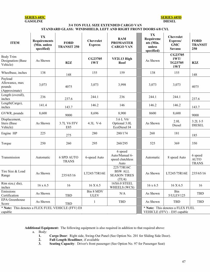
47
SERIES 685C SERIES 685D GASOLINE DIESEL
3/4 TON FULL SIZE EXTENDED CARGO VAN STANDARD GLASS: WINDSHIELD, LEFT AND RIGHT FRONT DOORS 6/8 CYL
Additional Equipment: The following equipment is also required in addition to that required above:
a. Body: 1. Cargo Door: Right side, Swing-Out Panel (See Option No. 201 for Sliding Side Door). 2. Full Length Headliner, if available 3. Seating Capacity: Driver's front passenger (See Option No. 97 for Passenger Seat)
ITEM
TX Requirements (Min. unless
specified)
FORD
TRANSIT 250
Chevrolet Express
RAM PROMASTER CARGO VAN
TX Requirements (Min.
unless specified)
Chevrolet Express/
GMC Savana
FORD TRANSIT 250
Body Trim Designation (Base Vehicle)
As Shown R2Z
CG23705 1WT
VF2L13 High Roof
As Shown
CG23705 1WT/
TG23705 1WT
R2Z
Wheelbase, inches 138 148 155 159 138 155
148 Payload Allowance, max pounds (Approximate)
3,073 4075 3,073 3,998
3,073 3,073 4075
Length (overall), inches 236
237.6 244.1 236 244.1 244.1 237.6
Length(Cargo), inches 141.4
143.7 146.2 146 146.2 146.2 143.7
GVWR, pounds 8,600 9000 8,696 8,900 8600 8,600
9000 Displacement, liters (Base Vehicle)
As Shown
3.7L V6 FFV E85
4.3L V-6 3.6 L V6/
Optional 3.0L EcoDiesel I4
As Shown 2.8L
Diesel 3.2L I-5 DIESEL
Engine HP 225 275 280 280/174 260 181
185
Torque 250
260
295 260/295
525 369
350
Transmission Automatic
6 SPD AUTO TRANS
6-speed Auto
6 speed Auto/Manual 6-speed clutchless
Auto
Automatic 8 speed Auto
6 speed AUTO TRANS
Tire Size & Load Range As Shown
235/65/16 LT245/75R16E
225/75R16C BSW ALL
SEASON TIRES (TU4)
As Shown LT245/75R16E 235/65/16
Rim size,( dia), inches 16 x 6.5 16 16 X 6.5 16X6.0 STEEL
WHEELS (WCS) 16 x 6.5 16 X 6.5 16
Emissions Certification As Shown
TBD Bin 8 MDV
ULEV N/A As Shown Bin 5/ULEV125 TBD
EPA Greenhouse Score As Shown
TBD 1 TBD As Shown TBD TBD
* Note: This denotes a FLEX FUEL VEHICLE (FFV) E8 capable
* Note: This denotes a FLEX FUEL VEHICLE (FFV) – E85 capable

48
SERIES 686C 1 TON FULL SIZE EXTENDED CARGO VAN , 6/8-CYL
STANDARD GLASS: WINDSHIELD, LEFT AND RIGHT FRONT DOORS
ITEM Minimum Requirements
RAM PROMASTER CARGO VAN
VF3L16
Freightliner Sprinter
3500
FORD
TRANSIT 350
Chevrolet Express
CG33705
GMC Savana
TG33705
Wheelbase, inches 138 159 144
148 155 155
Apprx. Payload Allowance lbs
3470 4,417 4364 4575 4120 4120
Overall Length, inches
232.5 236 232.5
266.1 244.1 244.1
Length, Cargo, inches 128.5
146 128.5 172.2 146.2 146.2
GVWR, pounds 9000 9350 9990
9500
9600 9600
Engine, Displacement, liters
As Shown 3.6 L V6/
Optional 3.0L EcoDiesel I4
3.7L V6 FFV* E85
4.8L V-8
4.8L V-8
Engine, HP 255 280/175 275 280 280
Engine, Torque 260 260/295
260 295 295
Transmission Automatic
6 speed Auto/Manual 6-speed clutchless
Auto transmission
6 SPD AUTO
8-Spd Auto 8-Spd Auto
Tire Size & Load Range As Shown
225/75R16C BSW ALL SEASON
TIRES (TU4)
235/65/16 P245/75R16E P245/75R16E
Rim Size, inches 6.5
16X6.0 STEEL WHEELS
(WCS 7 6.5 6.5
Emissions Certification As Shown TBD
TBD Bin 8 MDV ULEV
Bin 8 MDV ULEV
Additional Equipment: The following equipment is also required in addition to that required above:
a. Body:
1. Cargo Door: Right side, Swing-Out Panel (See Option No. 201 for Sliding Side Door).
2. Seating Capacity: Driver's front passenger (See Option No. 97 for Passenger Seat).
3. Full Length Headliner, if available

49
B.5. PASSENGER VANS, LIGHT-DUTY:
Unless otherwise specified, all units shall be furnished complete with standard equipment and factory-installed accessories as listed in the manufacturers’ printed literature for the models specified herein (See Section A.4.1. and Section B.1.1. of this document). The below items are minimum requirements for the models specified herein, and shall be provided whether shown as optional or standard equipment by the manufacturer. The following are some of those standard features or additional features as listed for these models. Please note any additional requirements following the table for each series number. These additional requirements listed below any table are in addition to, the following general requirements for Light-Duty Passenger Vans:
5.1. Body: 5.1.1. Air Bags: Required. Manufacturer’s standard to include side curtain/impact airbags if
available from manufacturer. 5.1.2. Air Conditioning: Manufacturer’s Front and Rear required. 5.1.3. Arm Rests, Door-Mounted: Both right and left arm rests are required. 5.1.4. AM/FM Radio: Manufacturer's standard. 5.1.5. Auxiliary Power Outlet: 12 volt. 5.1.6. Headliner: Required. Full length, if available. 5.1.7. Heater and Defroster: Required 5.1.8. Power Package: Includes power windows, power locks, power mirrors, cruise control, and tilt
steering wheel. (Select Option 87 to delete entire power package, not available from Nissan.) 5.1.9. Seat, Cloth: Front buckets, 2nd, 3rd, & 4th row bench seats, where applicable (Option 258 for
vinyl seats.) 5.1.10. Side Panels, Interior: Rigid material with a durable finish such as plastic shall be installed on
all walls and doors. 5.1.11. Sun Visor: Dual. 5.1.12. Windows, Passenger: Required (factory installed, if available) for each row of seats (Option
153). 5.1.13. Windshield Wipers: Dual electric 2-speed type with intermittent feature windshield washers. 5.1.14. Window Tint: OEM Standard Tint. Tinting shall meet Texas DPS regulations 5.1.15. Bluetooth Wireless Communication: OEM standard at no additional cost to Customer. 5.1.16. Back-up Camera: OEM standard, option should be at no additional cost to Customer
5.2. Chassis:
5.2.1. Automatic Transmission 5.2.2. Brakes, ABS, required, Manufacturer's standard, front disc, 2- or 4-wheel. 5.2.3. Traction Assistance and Vehicle stability enhancement system. 5.2.4. Bumpers: Manufacturer's standard front and rear. 5.2.5. Ground Ratings: As required for the GVWR certified. 5.2.6. Spare Wheel and Tire: Manufacturer's standard, mounted (Conventional Tire) – full-size spare
wheel and tire shall be A BRAND NAME, TYPE, AND SIZE OF TIRE to those on the vehicle, where available. (See Option 108 for space saver wheel and tire).
5.2.7. Tires, Including Spare, If Conventional Type: Steel-belted radial-type tubeless tires (all tires shall be identical).
5.2.8. Electronic Stability Control: Required ( per FMVSS 126 all light duty vehicles (under GVWR 10,000) to have ESC installed)
5.3. KEYS: At no additional cost, each vehicle will be delivered with three (3) ignition/door keys and three (3) fobs/remote keyless entry/ignition devices.*This applies to ALL vehicles on state contract, unless otherwise specified*
Note: the above are required options on the Series within this section. Ordering entities shall not pay additional cost for the requirement options. Charging a Customer for the above requirements may result in cancellation of award. Note: On specification tables, rim size means tire width, unless otherwise indicated.

50
PASSENGER VANS, LIGHT DUTY Refer to General Requirements, Preceding Each Group.
SERIES 741A
COMMERCIAL MINI VAN (5-PASSENGER) 4-CYLINDER, FRONT WHEEL DRIVE
Item Minimum Requirements
Ford Transit Connect *
Ram ProMaster
City Passenger van
Body Trim Designation (Base Vehicle) As Shown XL Passenger van
Wheelbase, inches 114.6 120.6 122.4 Length, Overall, inches 180.7 189.7 187.1 GVWR, pounds 4,965 5280 5,395
Engine, Displacement, liters As shown 2.5L 2.4L
Engine, HP 136 169 178 Engine, TORQUE 128 171 174
Transmission Automatic Automatic (6-speed)
9 speed auto
Tire Size & Load Range As Shown 215/55R16 215/55R16XL
BWS ALL SEASON TIRES
Rim Size, inches As Shown 6.5 6.5
Emissions Certification As Shown Tier 3 Bin 125 ULEV II
TBD
EPA Greenhouse Score As Shown 5 TBD * Note: This denotes a FLEX FUEL VEHICLE (FFV) – E85 capable at no extra cost
Additional Equipment: The following equipment is also required in addition to that required above:
1. Sliding Doors:
2. Seats - The minimum seating arrangement shall be as follows:
Rows Seat Capacity
1 One (driver) & One (passenger, front) 2 Three (per seat) 3 no seats

51
SERIES 741B 1/2 TON MINI VAN 6-CYLINDER, 7 -PASSENGER
Additional Equipment: The following equipment is also required in addition to that required above:
a. Body:
1. Sliding Doors, right and left side.
2. Seats - The minimum seating arrangement shall be as follows:
Rows Seat Capacity
1 One (driver) & One (passenger, front) 2 Three (per seat)
Item Minimum Requirements
Dodge Grand
Caravan
Nissan Quest
Toyota Sienna
Chrysler Pacifica
Body Trim (Base Vehicle) As Shown SE 3.5 SV 5328
Pacifica LX; with option for
Touring Hybrid Electric
Wheelbase, inches 118.1 121.2 118.1 119.3 121.6 Length, Overall, inches 200.2 202.5 200.8 200.2 203.6 GVWR, pounds 5818 6100 5818 5995 6005
Engine, Displacement, liters As shown 3.6L V-6 FFV * 3.5L V6 3.5L V6 3.6L V-6
Engine, HP 260 283 260 266 287 Engine, TORQUE 240 260 240 245 262 Transmission Automatic 6 speed CVT 6 speed auto 9 spd
Tire Size & Load Range As Shown 225/65R16 BSW All-
Season P265/60R18 P235/60R17
P235/65R17
Rim Size, inches As Shown 16X6.5 STEEL
WHEELS 7 6.5
Emissions Certification As Shown NAS BIN 4+ ULEV
II+
LEV2-ULEV / Tier
2, Bin 5 / Tier 2, Bin 5
(Non-50 State/Federal Emissions)
ULEV 2 Bin 5
EPA Greenhouse Score As Shown 5 TBD 4 * Note: This denotes a FLEX FUEL VEHICLE (FFV) – E85 capable at no extra cost.

52
SERIES 750C l/2 TON FULL SIZE PASSENGER VAN
6/8-CYLINDER, 8-PASSENGER
Item Minimum Requirements Ford Transit 150 *FFV E85
Body Trim Designation (Base Vehicle) As Shown XL
Wheelbase, inches 129.9 129.9 Approximate Payload Allowance 1779 2,980
Length, Overall, inches 216.7 219.9 GVWR, pounds 7300 8,550 Engine, Displacement, liters As Shown 3.7L V6 FFV
Engine, HP 225 275 Engine, TORQUE 250 260 Transmission Automatic 6-speed auto Tire Size & Load Range As Shown 235/65R16 BSW Rim Size, inches 7 16 Emissions Certification As Shown Bin 8
EPA Greenhouse Score As Shown 2
* Note: This denotes a FLEX FUEL VEHICLE (FFV) – E85 capable at no extra cost.
Note: For cutaway chassis with Para-transit bodies see Series 885CPT Additional Equipment: The following equipment is required in addition to that required above:
a. Body:
1. Swing out Side Door(s): Sliding (See Option No. 202 for Swing-Out Side Door).
2. Seats - The minimum seating arrangement shall be as follows:
Rows Seat Capacity
1 One (driver) & One (passenger, front) 2 Three (per seat) 3 Three (per seat)
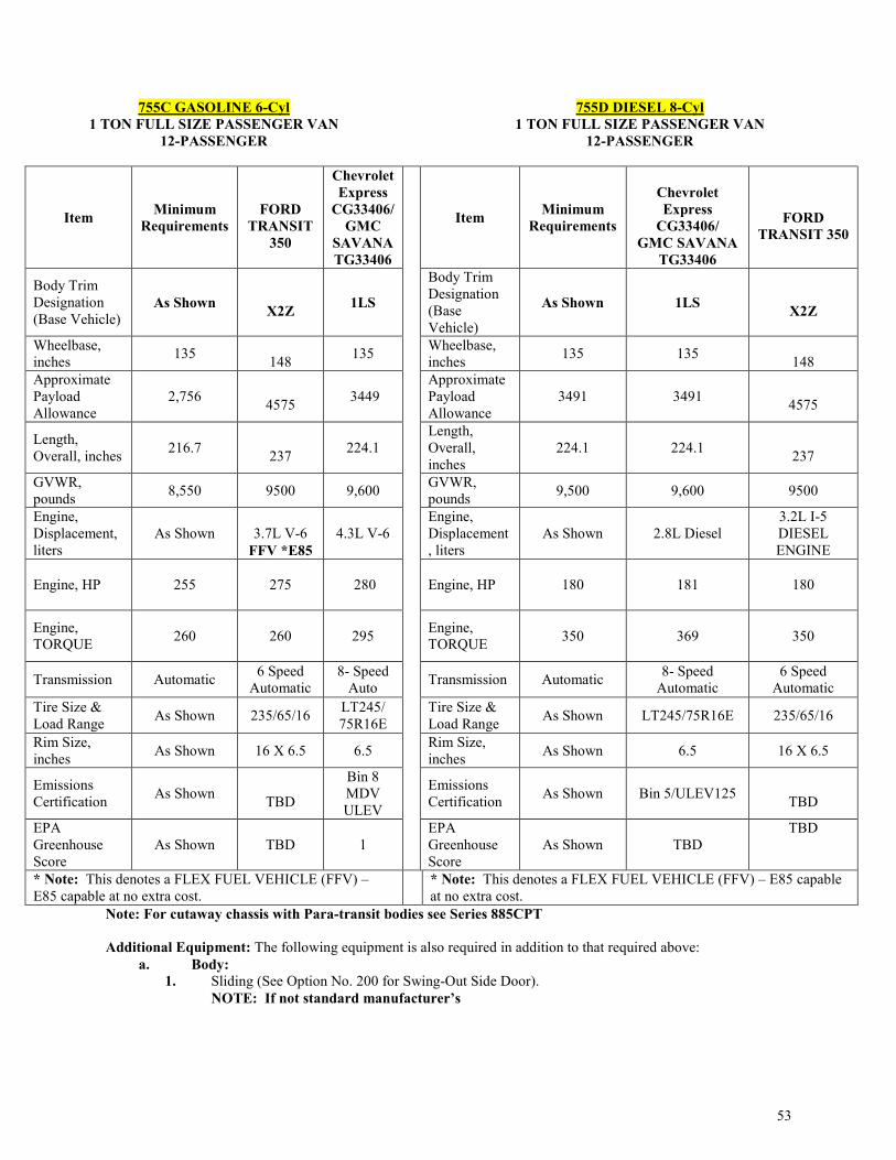
53
755C GASOLINE 6-Cyl 1 TON FULL SIZE PASSENGER VAN
12-PASSENGER
755D DIESEL 8-Cyl 1 TON FULL SIZE PASSENGER VAN
12-PASSENGER
Item Minimum Requirements
FORD
TRANSIT 350
Chevrolet Express
CG33406/ GMC
SAVANA TG33406
Item Minimum Requirements
Chevrolet Express
CG33406/ GMC SAVANA
TG33406
FORD
TRANSIT 350
Body Trim Designation (Base Vehicle)
As Shown X2Z 1LS
Body Trim Designation (Base Vehicle)
As Shown 1LS X2Z
Wheelbase, inches 135
148 135 Wheelbase, inches 135 135
148 Approximate Payload Allowance
2,756 4575 3449
Approximate Payload Allowance
3491 3491 4575
Length, Overall, inches 216.7
237 224.1 Length, Overall, inches
224.1 224.1 237
GVWR, pounds 8,550 9500 9,600 GVWR,
pounds 9,500 9,600 9500
Engine, Displacement, liters
As Shown
3.7L V-6 FFV *E85
4.3L V-6 Engine, Displacement, liters
As Shown 2.8L Diesel 3.2L I-5 DIESEL ENGINE
Engine, HP 255
275
280 Engine, HP 180 181
180
Engine, TORQUE 260
260
295 Engine,
TORQUE 350 369
350
Transmission Automatic 6 Speed Automatic
8- Speed Auto Transmission Automatic 8- Speed
Automatic 6 Speed
Automatic Tire Size & Load Range As Shown 235/65/16 LT245/
75R16E Tire Size & Load Range As Shown LT245/75R16E 235/65/16
Rim Size, inches As Shown 16 X 6.5 6.5 Rim Size,
inches As Shown 6.5 16 X 6.5
Emissions Certification As Shown
TBD
Bin 8 MDV ULEV
Emissions Certification As Shown Bin 5/ULEV125
TBD
EPA Greenhouse Score
As Shown TBD 1 EPA Greenhouse Score
As Shown TBD TBD
* Note: This denotes a FLEX FUEL VEHICLE (FFV) – E85 capable at no extra cost.
* Note: This denotes a FLEX FUEL VEHICLE (FFV) – E85 capable at no extra cost.
Note: For cutaway chassis with Para-transit bodies see Series 885CPT Additional Equipment: The following equipment is also required in addition to that required above:
a. Body: 1. Sliding (See Option No. 200 for Swing-Out Side Door). NOTE: If not standard manufacturer’s

54
760C GASOLINE 1 TON FULL SIZE EXTENDED PASSENGER VAN
6/8-CYLINDER,15-PASSENGER
760D DIESEL 1 TON FULL SIZE EXTENDED PASSENGER VAN,6/8-
CYLINDER,15-PASSENGER
Item Minimum Requirements
FORD
TRANSIT 350
Chevrolet CG33706/
GMC SAVANA TG33706
Item Minimum Requirements
Chevrolet CG33706
GMCSAVANA
TG33706
FORD
TRANSIT 350
Body Trim Designation (Base Vehicle)
As Shown X2Z 1LS
Body Trim Designation (Base Vehicle)
As Shown 1LS X2Z
Wheelbase, inches 138 148 155
Wheelbase, inches 148 155 148
Approximate Payload Allowance
2,668 4,575 3,146
Approximate Payload Allowance
3,171 3,389 4,275
Length, Overall, inches
237 237 244.1
Length, Overall, inches
237 244.1 237.6
GVWR, pounds 9,100 9,500 9,600
GVWR, pounds 9,500 9,600
9,500
Engine, Displacement, liters
As Shown 3.7L V6 FFV 4.3L V-6
Engine, Displacement, liters
As Shown 2.8L Diesel 3.2L I-5 DIESEL ENGINE
Engine, HP As Shown
275
280
Engine, HP As Shown 181
180
Engine, TORQUE As Shown
260
295
Engine, TORQUE As Shown 369
350
Transmission Automatic
6 SPD AUTO TRANSMISSI
ON
8-speed Automatic
Transmission Automatic 8- Speed Automatic
6 SPD AUTO
TRANS Tire Size & Load Range As Shown 235/65/16 LT245/75R
16E
Tire Size & Load Range As Shown LT245/75R16
E 235/65/16
Rim Size, inches 6.5 6.5 6.5
Rim Size, inches 6.5 6.5 6.5
Emissions Certification As Shown TBD
Bin 8 MDV ULEV
Emissions Certification As Shown Bin
5/ULEV125 TBD
EPA Greenhouse Score As Shown TBD 1
EPA Greenhouse Score
As Shown TBD TBD
* Note: This denotes a FLEX FUEL VEHICLE (FFV) – E85 capable at no extra cost.
* Note: This denotes a FLEX FUEL VEHICLE (FFV) – E85 capable at no extra cost.
Note: For cutaway chassis with Para-transit bodies see Series 885CPT Additional Equipment: The following equipment is required in addition to that required above:
a. Body: 1. Cargo Door: Right side, Swing-Out Panel (See Option No. 201 for Sliding Side Door). NOTE: If not standard manufacturer’s

55
2. Color: Limited number of standard colors available.
SERIES 771G EXTENDED HEIGHT 15 PASSENGER VAN
GASOLINE
ITEM Minimum Requirements
Lift Equipped Ford Transit 350
*FFV E85 Body Trim Designation (Base Vehicle) As Shown X2X
Interior Height 75.5 77.0 Wheelbase, inches 138 148 Approximate Payload Allowance, pounds 2652 2,810
Overall Length, inches 231 236.7 Length, Cargo, inches 129 TBD GVWR, pounds 9,000 9,000
Engine, Displacement, liters As shown 3.7L V6
Engine, HP 255 270 Engine, TORQUE 350 250 Transmission Automatic 6-speed auto Tire Size & Load Range As Shown 235/65R16 BSW Rim Size, inches 6 16 x 6.5 Emissions Certification As Shown TBD
a. Chassis: Stability Traction Control: Vehicle must include rollover stability control. Electronic
Stability Control: (per FMVSS 126 all light duty vehicles (under GVWR 10,000) to have ESC installed by model year 2012)
Note: For cutaway chassis with Para-transit bodies see Series 885CPT. The para-transit vehicles shall satisfy the specifications listed in Section H: Special Equipment: Para-transit Vehicles or Section I(a): Special Equipment-Para-transit Low Floor Body & Wheelchair Ramp. Para-transit up-fit may affect passenger capacity. Please check with the awarded Contractor for the specific configuration available for this series.
Following options may be available for conversion to para-transit vehicle.
Option 137: Wheelchair Lift securement for one wheelchair position. Option 138: Wheelchair Lift: securement for two wheelchair positions. Option 141: Para-transit Body: securement for two wheelchair positions with 8 ambulatory passengers. Option 144: Wheelchair Vehicle Fixed Route Options-Destination Signs, Public Information System and Stop Request Chime.

56
B.6 LIGHT-DUTY TRUCKS: Unless otherwise specified, all units shall be furnished complete with standard equipment and factory-installed accessories as listed in the manufacturer's printed literature for the models specified herein (See Section A.4.1. and Section B.1.1.). The following items are minimum requirements for the models specified herein, and shall be provided whether shown as optional or standard equipment by the manufacturer. The following are some of those standard features or additional features as listed for these models. Please note any additional requirements following the table for each series number. These additional requirements listed below any table are in addition to, the following general requirements for Light-duty Trucks:
6.1. Body: Pickup or Cab and Chassis.
6.1.1. Pickup Bodies: Straight / fleet side with steel cargo floors.
6.2. Cab: Conventional, Extended, or Crew. 6.2.1. Air Bags: Required. Manufacturer’s standard to include side curtain/impact airbags if available
from manufacturer [Exception: Units with 8,600 lb. GVWR and up.] 6.2.2. Air Conditioning: Required. Manufacturer's standard. 6.2.3. AM/FM Radio: Manufacturer's standard. 6.2.4. Auxiliary Power Outlet: One(1) 12 volt. 6.2.5. Seat, Cloth: Front seats split bench 40/60, 40/20/40, or buckets. (Bench not acceptable) (Option
No. 258 is for vinyl seats.) 6.2.6. Jack, Handle, and Lug Wrench. 6.2.7. Power Package: Includes power windows, power locks, power mirrors, cruise control, and tilt
steering wheel. (Option No. 87 to delete entire power package, not available from Nissan. 6.2.8. Mirrors: Rearview Mirrors shall be the largest factory installed available. 6.2.9. Sun Visors: Dual. 6.2.10. Window Tint: OEM Standard Tint. Tinting shall meet Texas DPS regulations. (see Option # 140) 6.2.11. Bluetooth Wireless Communication: OEM standard at no additional cost to Customer. 6.2.12. Back-up Camera: If option is a manufacturer’s standard, it should be at no additional cost to
Customer. 6.3. Chassis:
6.3.1. Automatic Transmission: Required 6.3.2. Brakes, ABS, required, Manufacturer's standard; front disc, 2- or 4- wheel. 6.3.3. Bumper (Full Width of Truck): Installed front and rear-step bumper shall be manufacturer's
standard (except cab and chassis units - See Sections F., G., and H. for body specifications). 6.3.4. Spare Wheel and Tire: OEM full-size (See Option No. 116 for All Terrain Tires). 6.3.5. Tires (including Spare): Steel belted radial, all position, tubeless highway tread. Tires with raised
white lettering are acceptable, if mounted with the black lettering facing away from vehicle. 6.3.6. Electronic Stability Control: Required (per FMVSS 126 all light duty vehicles (under GVWR
10,000) to have ESC installed)
6.4. Cargo Weight: 6.4.1. Cargo Weight: Deduct the cargo body weight from the body and payload allowance shown. The
remainder is the cargo weight limit for the standard, base truck. 6.4.2. Payload Allowance: Weight of cargo that may be carried by the standard, base vehicle. (See
definition of Payload Allowance in Section A.2.1 – Abbreviations and Definitions)
6.5. KEYS: At no additional cost, each vehicle will be delivered with three (3) ignition/door keys and three (3) fobs/remote keyless entry/ignition devices. This applies to ALL vehicles on state contract, unless otherwise specified
Note: the above are required options on the Series within this section. Ordering entities shall not pay additional cost for the requirement options. Charging a Customer for the above requirements may result in cancellation of award. Note: On specification tables, rim size means tire width, unless otherwise indicated.

57
LIGHT-DUTY TRUCKS Refer to General Requirements, Preceding Each Group.
SERIES 843B
MID-SIZE CREW CAB PICKUP TRUCK SINGLE REAR WHEEL
5/6-CYLINDER, SHORT BED 1/2 TON 4 Full Door
ITEM Minimum Requireme
nts Nissan Frontier SV Toyota Tacoma Chevrolet
Colorado GMC Canyon
Body Trim Designation (Base Vehicle)
As Shown 4x2 7186 12M43WT T2M43
Wheelbase, inches 125.9 125.9 127.4 128.3 128.3
Approximate Payload Allowance, pounds
1,422 1,422 1430 1572
1575
Length, Overall, inches As Shown 205.5 208.1 212.7 212.7
Length, Cargo, inches 59.5 59.5 60.3 62 62
GVWR, pounds 4900 5,730 5,600 6000 6000 Engines, Displacement, liters
As Shown 4.0L V-6 4.0L V-6 3.6L V6 3.6L V6
Engines, Net HP As Shown 261 236
308
308 Engines, TORQUE 266 281 266
275
275 Transmission Automatic 5 speed auto 5 speed 8 speed auto 8 speed auto Tire Size & Load Range As Shown P265/70R16 P245/75R16 P265/70R16 P265/70R16
Rim Size, inches As Shown 7 7 7 7
Emissions Certification As Shown Tier2Bin5 (FED) /
LEVII LEV (California) LEV2 Bin 5 BIN 4 /ULEV2 BIN4 /ULEV2
EPA Greenhouse Score
As Shown TBD 3 5 5
Additional Equipment: The following equipment is required in addition to that required above:
a. Body:
1. Seats: Seating shall be provided for a minimum for 4 persons, including driver (See Option No. 98 for Rear Seat Delete Option * Note: Not available from GM or Nissan).
2. Front Seat: 40/60 Split bench front seat. Nissan and Ford front seats are only bucket.

58
SERIES 844B MID-SIZE EXTENDED CAB PICKUP TRUCK
SINGLE REAR WHEEL, 5/6-CYLINDER SHORT BED
ITEM Minimum Requirements
Toyota Tacoma
Access Cab Nissan Frontier Chevrolet
Colorado GMC Canyon
Body Trim Designation (Base Vehicle)
As Shown 7164 PreRunner KC SV 4 x 2 12M53WT T2M53
Wheelbase, inches 125.9 127.4 125.9 128.3 128.3 Approximate Payload Allowance, pounds
1415 1415 1,447 1572
1575
Length, Overall, inches 205.5 208.1 205.5 212.7 212.7
Length, Cargo, inches 73.3 73.5 73.3 74 74
GVWR, pounds 5250 5250 5,589 6000 6000 Engines, Displacement, liters As Shown 4.0L V-6 4.0L V-6 3.6L V6 3.6L V6
Engines, Net HP 236 236 261 305
305
Engines, TORQUE 266 266 281 275
275
Transmission Automatic 5 speed Auto. 5 speed auto 8 speed auto 8 speed auto Tire Size & Load Range As Shown P245/R7516 P265/70R16 P265/70R16 P265/70R16
Rim Size, inches As Shown 16 x 7 16 x 7 16 x 7 16 x 7
Emissions Certification As Shown LEV 2 Bin 5
Tier2Bin5 (FED) / LEVII LEV (California)
BIN 4 /ULEV2 BIN 4 /ULEV2
EPA Greenhouse Score As Shown 3 TBD 5 5
Additional Equipment: The following equipment is also required in addition to that required above:
a. Body:
1. Seats: Seating shall be provided for a minimum for 4 persons, including driver (See Option No. 98 for Rear Seat Delete Option* Note: Not available from GM and Nissan).
2. Front Seat: Bucket or split bench.

59
SERIES 855B FULL SIZE 1/2 TON REGULAR CAB PICKUP TRUCK SINGLE REAR WHEEL, 6-CYLINDER, SHORT BED
ITEM Minimum Requirements RAM 1500 Ford F 150*
FFV Chevrolet
Silverado * GMC
Sierra * Body Trim Designation (Base Vehicle) As Shown DS1L61
TRADESMAN F1CXL CC15703 1WT
TC15703 1SA
Wheelbase, inches 119 120.5 122.4 119 119 Approximate Payload Allowance, pounds 1430 1430 1,610
1960
1960 Length, Overall, inches 205.6 209 209.3 205.6 205.6 Length, Cargo, inches 76.3 76.3 78.9 78.9 78.9
GVWR, pounds 6,010 6,010 6,050 6,700
6,700
Engines, Displacement, liters As Shown 3.6L V6*FFV 3.5L V6
*FFV E85 4.3L V6*E85
FFV 4.3L V6*E85 FFV
Engines, Net HP 195 305 282 285 285
Engines, TORQUE 250 269 253 305
305
Transmission Automatic 8HP45
8-speed Automatic
6 speed auto 6 Speed OD
6 Speed OD
Tire Size & Load Range As Shown P265/70R17 BSW All-Season 245/70R17
P255/70R17
P255/70R17 Rim Size, inches As Shown 17X7.0 STEEL 17 X 7.5 17 X 8.0 17 X 8.0
Emissions Certification As Shown BIN 4 + ULEV II + Bin 4 Bin 4 ULEV2 Bin 4 ULEVS
EPA Greenhouse Score As Shown 5 4 5 5 * Note: This denotes a FLEX FUEL VEHICLE (FFV) – E85 capable at no extra cost.

60
SERIES 855C
FULL SIZE 1/2 TON REGULAR CAB PICKUP TRUCK SINGLE REAR WHEEL
8-CYLINDER, SHORT BED
ITEM Minimum Requirements
RAM 1500 FFV
Ford F150* FFV
Chevrolet Silverado FFV
GMC Sierra *FFV
Body Trim Designation (Base Vehicle) As Shown DS1L61
TRADESMAN F1C - XL CC15703
1WT TC15703
1SA Wheelbase, inches 119 120.5 122.4 119 119 Approximate Payload Allowance, pounds 1,690 1690 1,760
1,870
1,870 Length, Overall, inches 205.6 209 209.3 205.6 205.6 Length, Cargo, inches 76.3 76.3 78.9 78.9 78.9
GVWR, pounds 6,400 6,600 6,400 6700
6700
Engines, Displacement, liters As shown 5.7 L V8 5.0L V8 5.3L V-8 *E85 FFV 5.3L V-8
*E85 FFV Engines, Net HP 302 395 *E85 FFV 355 355 Engines, TORQUE 305 407 385 383 383
Transmission Automatic 8-speed Automatic
387 6-SPEED OD 6-SPEED OD
Tire Size & Load Range As Shown P265/70R17
BSW All Season Tires
6 speed auto P255/70R17 P255/70R17
Rim Size, inches As Shown 17X7 245/70R17 17 X 8.0 17 X 8.0 Emissions Certification As Shown BIN 4 ULEV II 17x7.5 Bin 4 ULEV2 Bin 4 ULEV2 EPA Greenhouse Score As Shown 3 Bin 4 ULEV II 4 4 * Note: This denotes a FLEX FUEL VEHICLE (FFV) – E85 capable at no extra cost.
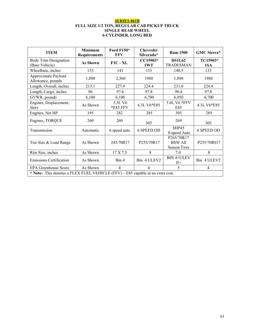
61
SERIES 861B FULL SIZE 1/2 TON, REGULAR CAB PICKUP TRUCK
SINGLE REAR WHEEL 6-CYLINDER, LONG BED
ITEM Minimum Requirements
Ford F150* FFV
Chevrolet Silverado* Ram 1500 GMC Sierra*
Body Trim Designation (Base Vehicle) As Shown F1C - XL CC15903*
1WT DS1L62
TRADESMAN TC15903*
1SA Wheelbase, inches 133 141 133 140.5 133 Approximate Payload Allowance, pounds 1,890 2,360 1980 1,890 1980
Length, Overall, inches 213.1 227.9 224.4 231.0 224.4 Length, Cargo, inches 96 97.6 97.8 98.4 97.8 GVWR, pounds 6,100 6,100 6,700 6,950 6,700 Engines, Displacement, liters As Shown 3.5L V6
*E85 FFV 4.3L V6*E85 3.6L V6 *FFV E85 4.3L V6*E85
Engines, Net HP 195 282 285 305 285
Engines, TORQUE 260 260 305 269
305
Transmission Automatic 6 speed auto 6 SPEED OD 8HP45 8-speed Auto 6 SPEED OD
Tire Size & Load Range As Shown 245/70R17 P255/70R17 P265/70R17
BSW All Season Tires
P255/70R017
Rim Size, inches As Shown 17 X 7.5 8 7.0 8
Emissions Certification As Shown Bin 4 Bin 4 ULEV2 BIN 4+ULEV II+ Bin 4 ULEV2
EPA Greenhouse Score As Shown 4 4 5 4 * Note: This denotes a FLEX FUEL VEHICLE (FFV) – E85 capable at no extra cost.

62
SERIES 861C FULL SIZE 1/2 TON, REGULAR CAB PICKUP TRUCK
SINGLE REAR WHEEL 8-CYLINDER, LONG BED
ITEM Minimum Requirements
Ford F150* FFV
Chevrolet Silverado*
FFV Ram 1500 GMC Sierra *
FFV
Body Trim Designation (Base Vehicle) As Shown F1C - XL CC15903
1WT DS1L62
TRADESMAN CC15903
1SA Wheelbase, inches 133 141 133 140.5 133 Approximate Payload Allowance, pounds 1,880 2,200 1980 1,880 1980
Length, Overall, inches 224 227.9 224.4 231.0 224. 4 Length, Cargo, inches 97.6 97.6 97.8 98.3 97.8 GVWR, pounds 6,800 6,950 6,800 6,950 6,800 Engines, Displacement, liters As Shown 5.0L V8
*E85 FFV 5.3L V8
*E85 5.7 L V8 5.3L V8 E85
Engines, Net HP 302 385 355 395 355 Engines, TORQUE 305 387 383 407 383
Transmission Automatic 6 Speed auto 6 Speed OD 8 Speed 6 Speed OD
Tire Size & Load Range As Shown 245/70R17 P255/70R17 P265/70R17 BSW P255/70R017
Rim Size, inches As Shown 17 X 7.5 17 X 8 17X7.0 17 X 8
Emissions Certification As Shown Bin 4 ULEV II Bin 4 ULEV2 NAA BIN 8 Bin 4 ULEV2
EPA Greenhouse Score As Shown 4 4 3 4 * Note: This denotes a FLEX FUEL VEHICLE (FFV) – E85 capable at no extra cost.

63
SERIES 862B FULL SIZE 1/2 TON EXTENDED CAB PICKUP TRUCK
SINGLE REAR WHEEL, 6-CYLINGER 5-PASSENGER, SHORT BED
ITEM Minimum Requirements
Chevrolet Silverado*
Ford F 150* FFV
Toyota Tundra
Double Cab
GMC Sierra*
Ram Quad Cab 1500 FFV
Body Trim Designation (Base Vehicle) As Shown CC15753
1WT X1C - XL 8215 Base TC15753 1SA
DS1L41 TRADESMA
N Wheelbase, inches 140.5 143.5 145 145.7 143.5 140.5 Approximate Payload Allowance, pounds 1,450
1890 1,680 1,450 1890 1,800
Length, Overall, inches 228.7 230. 0 231.9 228.7 230. 0 229.0 Length, Cargo, inches 73.9 78. 9 78 78.7 78. 9 73.9 GVWR, pounds 6,100 6,900 6,100 6400 6,900 6,700 Engines, Displacement, liters As Shown 4.3L V6
*E85 FFV 3.5L V6
*E85 FFV 4.0L V6 4.3L V6* E85 FFV
3.6L V6 *FFV E85
Engines, Net HP 195 285 282 236 285 305
Engines, TORQUE 250 305 253 266
305 269
Transmission Automatic 6-SPEED Auto OD 6 speed auto 5-Speed Auto 6-SPEED
Auto OD 8-speed
Automatic
Tire Size & Load Range As Shown P255/70R17 245/70R17 P255/70R18
P255/70R1
7
P265/70R17 BSW All
Season Tires Rim Size, inches As Shown 8 7 8 8 7.0
Emissions Certification As Shown Bin 4 ULEV2 Bin 4 18V8.0 Bin 4
ULEV2 NAS BIN 4+
ULEV II+ EPA Greenhouse Score As Shown 4 4 3 4 5 * Note: This denotes a FLEX FUEL VEHICLE (FFV) – E85 capable at no extra cost.
Additional Equipment: The following equipment is also required in addition to that required above:
a. Body:
1. Seats: Seating shall be provided for a minimum of 5 persons, including driver (See Option No. 98 for Rear Seat Delete Option. This option is not available from Nissan).
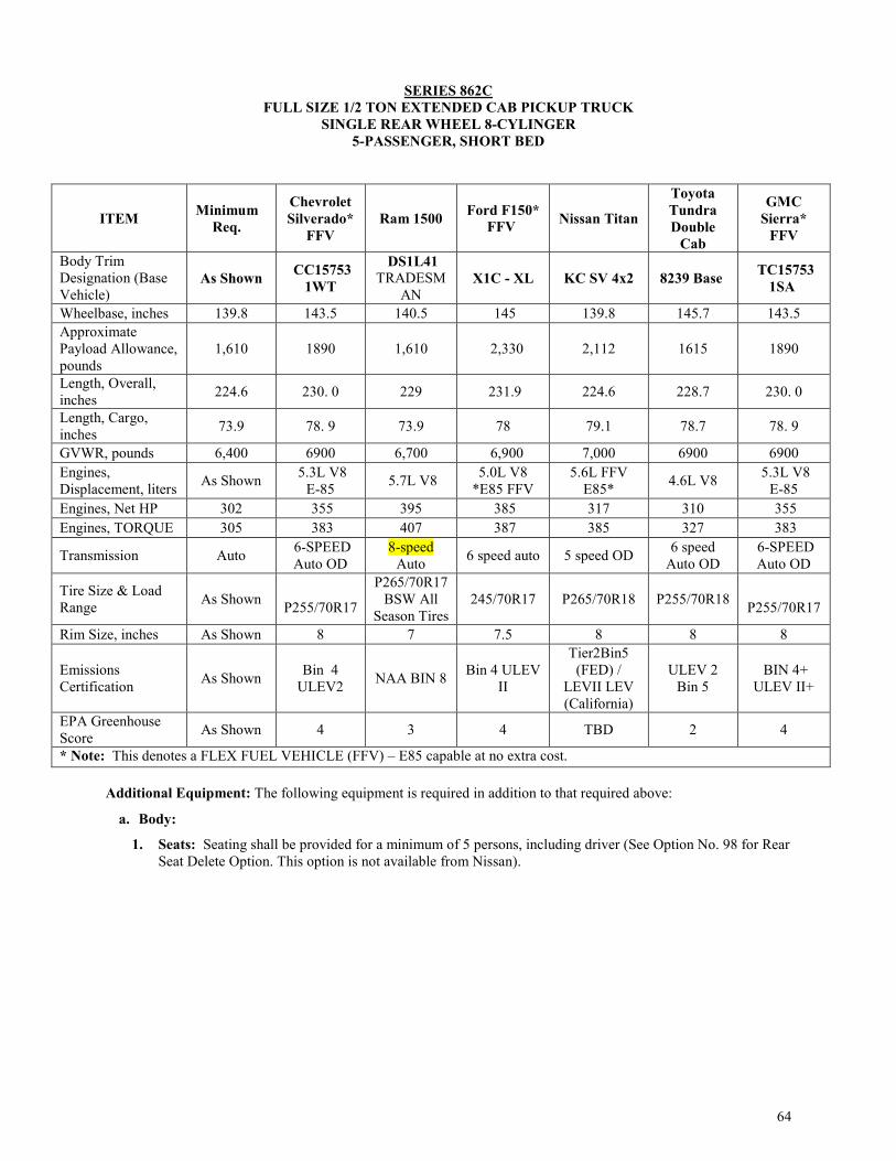
64
SERIES 862C
FULL SIZE 1/2 TON EXTENDED CAB PICKUP TRUCK SINGLE REAR WHEEL 8-CYLINGER
5-PASSENGER, SHORT BED
ITEM Minimum Req.
Chevrolet Silverado*
FFV Ram 1500 Ford F150*
FFV Nissan Titan
Toyota Tundra Double
Cab
GMC Sierra*
FFV
Body Trim Designation (Base Vehicle)
As Shown CC15753 1WT
DS1L41 TRADESM
AN X1C - XL KC SV 4x2 8239 Base TC15753
1SA
Wheelbase, inches 139.8 143.5 140.5 145 139.8 145.7 143.5 Approximate Payload Allowance, pounds
1,610 1890 1,610 2,330 2,112 1615 1890
Length, Overall, inches 224.6 230. 0 229 231.9 224.6 228.7 230. 0
Length, Cargo, inches 73.9 78. 9 73.9 78 79.1 78.7 78. 9
GVWR, pounds 6,400 6900 6,700 6,900 7,000 6900 6900 Engines, Displacement, liters As Shown 5.3L V8
E-85 5.7L V8 5.0L V8 *E85 FFV
5.6L FFV E85* 4.6L V8 5.3L V8
E-85 Engines, Net HP 302 355 395 385 317 310 355 Engines, TORQUE 305 383 407 387 385 327 383
Transmission Auto 6-SPEED Auto OD
8-speed Auto 6 speed auto 5 speed OD 6 speed
Auto OD 6-SPEED Auto OD
Tire Size & Load Range As Shown
P255/70R17
P265/70R17 BSW All
Season Tires 245/70R17 P265/70R18 P255/70R18
P255/70R17
Rim Size, inches As Shown 8 7 7.5 8 8 8
Emissions Certification As Shown Bin 4
ULEV2 NAA BIN 8 Bin 4 ULEV II
Tier2Bin5 (FED) /
LEVII LEV (California)
ULEV 2 Bin 5
BIN 4+ ULEV II+
EPA Greenhouse Score As Shown 4 3 4 TBD 2 4
* Note: This denotes a FLEX FUEL VEHICLE (FFV) – E85 capable at no extra cost. Additional Equipment: The following equipment is required in addition to that required above:
a. Body:
1. Seats: Seating shall be provided for a minimum of 5 persons, including driver (See Option No. 98 for Rear Seat Delete Option. This option is not available from Nissan).

65
SERIES 863C
FULL SIZE 1/2 TON EXTENDED CAB PICKUP TRUCK 5 PASSENGERS, LONG BED
6/8 CYLINDER SINGLE REAR WHEEL
ITEM Minimum Requirements Ford F150* FFV Toyota Tundra
Body Trim Designation (Base Vehicle) As Shown X1C - XL 8245
Wheelbase, inches 145.7 163 145.7 Approximate Payload Allowance, pounds 1641 2,330 1645
Length, Overall, inches 247.6 250.5 247.6 Length, Cargo, inches 96 96 97.6 GVWR, pounds 7,000 7,000 7,000 Engines, Displacement, liters As shown 5.0L V8 *E85 FFV 5.7L V8
Engines, Net HP 315 385 381 Engines, TORQUE 335 387 401
Transmission As shown 6 speed auto 6-speed Auto OD
Tire Size & Load Range As shown 245/70R17 P255/70R18
Rim Size, inches As Shown 17 X 7.5 18 X 8.0 Emissions Certification As shown Bin 4 ULEV II ULEV II EPA Greenhouse Score As Shown 4 1 * Note: This denotes a FLEX FUEL VEHICLE (FFV) – E85 capable at no extra cost.
Additional Equipment: The following equipment is required in addition to that required above:
a. Body:
1. Seats: Seating shall be provided for a minimum of 5 persons, including driver. (See Option 98 for Rear Seat Delete option)

66
SERIES 864C
FULL SIZE1/2 TON, CREW CAB PICK UP TRUCK 6 PASSENGERS, SHORT BED
8-CYLINDERS SINGLE REAR WHEEL
ITEM Minimum Requirements
Ram 1500 Crew Cab
Chevrolet Silverado*
Ford F150* FFV
Nissan Titan SV
Toyota Tundra
Crew Max
GMC Sierra*
Body Trim Designation (Base Vehicle)
As Shown DS1L98 Tradesman
CC15543 1WT W1C - XL Crew Cab
4x2 8259 TC15543 1SA
Wheelbase, inches 139.8 140.5 143.5 145 139.8 145.7 143.5 Approximate Payload Allowance, pounds
1550 1620 1840 2,130 2015 1550 1840
Length, Overall, inches 224.6 229.0 230. 0 231.9 224.6 228.7 230. 0
Length, Cargo, inches 66.7 67.4 69.3 67.1 67.3 66.7 69.3
GVWR, pounds 6,800 6,800 6,900 6,800 7,101 6800 6,900 Engines, Displacement, liters
As Shown 5.7L V-8 5.3L V8 E-85
5.0L V8 *E85 FFV
5.6L FFV E85* 4.6L V8 5.3L V8
E-85
Engines, Net HP 302 395 355 385 317 310 355 Engines, TORQUE 305 407 383 387 385 327 383
Transmission Automatic 8-Speed Automatic
6-speed Auto OD
6 speed auto 5-speed OD 6 speed OD 6-speed
Auto OD
Tire Size & Load Range Single Rear
P265/70R17 BSW All Season Tires
P255/70R17
245/70R17 P265/70R18 P255/70R18
P255/70R17
Rim Size, inches As Shown 7 17 X 8 17 x 7 8 18 X 8 17 X 8
Emissions Certification As Shown NAA BIN 8 Bin 4
ULEV2 Bin 4
ULEV II
Tier2Bin5 (FED) /
LEVII LEV (California)
ULEV 2 Bin 4 ULEV2
EPA Greenhouse Score As Shown 3 4 4 TBD 2 4
* Note: This denotes a FLEX FUEL VEHICLE (FFV) – E85 capable at no extra cost. Additional Equipment: The following equipment is required in addition to that required above:
a. Body:
1. Seats: Seating shall be provided for a minimum of 6 persons, including driver (See Option No. 98 for rear seat Delete Option. This option is not available from Nissan).

67
SERIES 866C FULL SIZE 3/4-TON, CREW CAB PICKUP TRUCK
6 PASSENGERS, SHORT BED 8-CYLINDER, GASOLINE
SINGLE REAR WHEEL DRIVE
ITEM Minimum Requirements
Ram 2500 Crew Cab
Chevrolet Silverado* (GT5) 4.10 Rear Axle
Ratio
Ford F 250SD* FFV
GMC Sierra*
(GT5) 4.10 Rear Axle
Ratio Body Trim Designation (Base Vehicle)
As Shown DJ2L91 TRADESMAN
CC25743 1WT XL TC25743
1SA
Wheelbase, inches 149.5 149.5 153.70 159.8 153.70
Approximate Payload Allowance, pounds
2,900 2,930 3,233 3880 3,233
Length, Overall, inches 237.4 237.4 239.5 250.0 239.5
Length, Cargo, inches 76.3 76.3 78.8 79 78.8
GVWR, pounds 8800 8,800 9,500 10,000 9,500 Engines, Displacement, liters
As Shown 5.7L V8/option 6.4L V8 6.0L V-8 E85* 6.2L V8 FFV
E85 * 6.0L V-8
E85*
Engines, Net HP 360 383/410 360 385 360 Engines, TORQUE 380 400/429 380 430 380
Transmission Automatic 6 Speed OD 6-speed OD 6-Speed 6-speed OD
Tire Size & Load Range Single Rear LT245/70R17E
BSW LT245/75R17 LT245/75R17 LT245/75R17
Rim Size, inches 17 X 7.5 17 X 7.5 17 X 7.5 17 X 7.5 17 X 7.5
Emissions Certification As Shown
NAS HDV1,MDV1,ULEV
II HDV/LEV395 HDV/LEV395 HDV/LEV395
EPA Greenhouse Score As Shown TBD TBD TBD TBD
* Note: This denotes a FLEX FUEL VEHICLE (FFV) – E85 capable at no extra cost. Additional Equipment: The following equipment is also required in addition to that required above:
a. Cab:
1. Seats: Seating shall be provided for a minimum of 5 persons, including driver (See Option No. 98 for Rear Seat Delete Option).
2. Mirrors, Exterior, Trailer Tow/Camper Type, Both Sides: Each mirror shall be approximately 6 inch by 9 inch and equipped with extension arms.

68
SERIES 866D FULL SIZE 3/4-TON, CREW CAB PICKUP TRUCK
6 PASSENGERS, SHORT BED 6/8 CYLINDER, DIESEL
ITEM Minimum Requirements
Ram 2500 Crew Cab Chevrolet Silverado Ford F 250 GMC
Sierra Body Trim Designation (Base Vehicle)
As Shown DJ2L91 TRADESMAN
CC25743 1WT XL TC25743
1SA
Wheelbase, inches 149.5 149.5 153.70 159.8 153.70 Approximate Payload Allowance, pounds 2,650 3120
2,803 3080 2,803
Length, Overall, inches 237.4 237.4 239.5 250.0 239.5 Length, Cargo, inches 76.3 76.3 78.8 79 78.8 GVWR, pounds 9000 10000 9,500 10,000 9,500 Engines, Displacement, liters AS Shown 6.7L I-6 DIESEL
B20 6.6L V-8Diesel B20 6.7 V-8 DIESEL B20
6.6L V-8Diesel B20
Engines, Net HP 350 370 445 440
445
Engines, TORQUE 650 800 910 925
910
Transmission Automatic 6 Speed OD 6-speed OD 6-Speed 6-speed OD
Tire Size & Load Range Single Rear LT245/70R17E
BSW LT245/75R17 LT245/75R17 LT245/75R17
Rim Size, inches As Shown 17 X 7.5 17 X 7.5 17 X 7.5 17 X 7.5 Emissions Certification As Shown HDV1,MDV1,ULEV
II HDV/ULEV2 HDV/ULEV2 HDV/ULEV2
EPA Greenhouse Score As Shown TBD TBD TBD TBD
* Note: This denotes a FLEX FUEL VEHICLE (FFV) – E85 capable at no extra cost.
Additional Equipment: The following equipment is required in addition to that required above:
a. Cab:
1. Seats: Seating shall be provided for a minimum of 6 persons, including driver (See Option No. 98 for Rear Seat Delete Option---- Note: GM does not have this delete option).
2. Mirrors, Exterior, Trailer Tow/Camper Type, Both Sides: Each mirror shall be approximately 6 inch by 9 inch and equipped with extension arms.
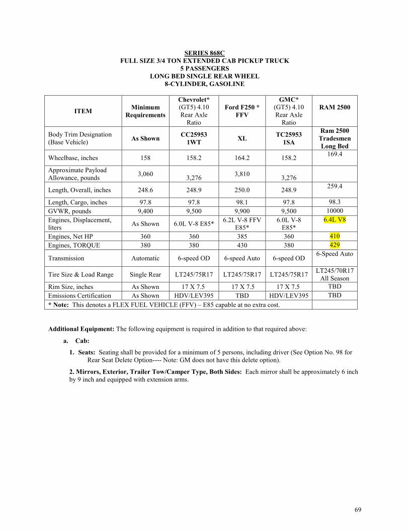
69
SERIES 868C
FULL SIZE 3/4 TON EXTENDED CAB PICKUP TRUCK 5 PASSENGERS
LONG BED SINGLE REAR WHEEL 8-CYLINDER, GASOLINE
ITEM Minimum Requirements
Chevrolet* (GT5) 4.10 Rear Axle
Ratio
Ford F250 * FFV
GMC* (GT5) 4.10 Rear Axle
Ratio
RAM 2500
Body Trim Designation (Base Vehicle) As Shown CC25953
1WT XL TC25953 1SA
Ram 2500 Tradesmen Long Bed
Wheelbase, inches 158 158.2 164.2 158.2 169.4
Approximate Payload Allowance, pounds 3,060
3,276 3,810 3,276
Length, Overall, inches 248.6 248.9 250.0 248.9 259.4
Length, Cargo, inches 97.8 97.8 98.1 97.8 98.3 GVWR, pounds 9,400 9,500 9,900 9,500 10000 Engines, Displacement, liters As Shown 6.0L V-8 E85* 6.2L V-8 FFV
E85* 6.0L V-8
E85* 6.4L V8
Engines, Net HP 360 360 385 360 410 Engines, TORQUE 380 380 430 380 429
Transmission Automatic 6-speed OD 6-speed Auto 6-speed OD 6-Speed Auto
Tire Size & Load Range Single Rear LT245/75R17 LT245/75R17 LT245/75R17 LT245/70R17 All Season
Rim Size, inches As Shown 17 X 7.5 17 X 7.5 17 X 7.5 TBD Emissions Certification As Shown HDV/LEV395 TBD HDV/LEV395 TBD * Note: This denotes a FLEX FUEL VEHICLE (FFV) – E85 capable at no extra cost. Additional Equipment: The following equipment is required in addition to that required above:
a. Cab:
1. Seats: Seating shall be provided for a minimum of 5 persons, including driver (See Option No. 98 for Rear Seat Delete Option---- Note: GM does not have this delete option).
2. Mirrors, Exterior, Trailer Tow/Camper Type, Both Sides: Each mirror shall be approximately 6 inch by 9 inch and equipped with extension arms.

70
SERIES 868D FULL SIZE 3/4 TON EXTENDED CAB PICKUP TRUCK 5 PASSENGERS, LONG BED, SINGLE REAR WHEEL
8-CYLINDER, DIESEL
ITEM Minimum Requirements Chevrolet Ford F250 GMC
RAM 2500
Body Trim Designation (Base Vehicle) As Shown CC25953
1WT XL TC25953 1SA
Ram 2500 Tradesmen Long Bed
Diesel Wheelbase, inches 158 158.2 164.2 158.2 169.4 Approximate Payload Allowance, pounds 2,910
3,276 3,810 3,276
169.4
Length, Overall, inches 248.6 248.9 250.0 248.9 259.4 Length, Cargo, inches 97.8 97.8 98.1 97.8 98.3 GVWR, pounds 10,000 10,000 10,000 10,000 10,000 Engines, Displacement, liters As Shown 6.6L V-8
Diesel B20 6.7L V-8
DIESEL B20 6.6L V-8
Diesel B20
Engines, Net HP 370 445 440 445 370 Engines, TORQUE 765 910 925 910 800
Transmission Automatic 6-speed OD 6-Speed Auto 6-speed OD
6-Speed
Tire Size & Load Range Single Rear LT245/75R17 LT245/75R17 LT245/75R17 LT245/70R17 Rim Size, inches As Shown 17 X 7.5 17 X 7.5 17 X 7.5 Emissions Certification As Shown HDV/ULEV2 TBD HDV/ULEV2 EPA Greenhouse Score As Shown TBD TBD TBD TBD * Note: This denotes a FLEX FUEL VEHICLE (FFV) – E85 capable at no extra cost. Additional Equipment: The following equipment is required in addition to that required above:
a. Cab:
1. Seats: Seating shall be provided for a minimum of 5 persons, including driver (See Option No. 98 for Rear Seat Delete Option---- Note: GM does not have this delete option).
2. Mirrors, Exterior, Trailer Tow/Camper Type, Both Sides: Each mirror shall be approximately 6 inch by 9 inch and equipped with extension arms.

71
SERIES 869C
FULL SIZE 3/4 TON EXTENDED CAB PICKUP TRUCK 5 PASSENGERS, SHORT BED, SINGLE REAR WHEEL
8-CYLINDER, GASOLINE
ITEM Minimum Requirements
Chevrolet Silverado * (GT5) 4.10 Rear Axle
Ratio
Ford F250 * FFV
GMC Sierra* (GT5) 4.10 Rear Axle
Ratio
Ram 2500 Tradesman
Body Trim Designation (Base Vehicle) As Shown CC25753
1WT XL TC25753 1SA
Short Bed Gas
Wheelbase, inches 141.8 144.2 148 144.2 149.5 Approximate Payload Allowance, pounds 3,020
3,381 3,900 3,381
Length, Overall, inches 230 230 238.2 230 237.4 Length, Cargo, inches 78.8 78.8 81.9 78.8 GVWR, pounds 9,400 9,500 9,900 9,500 10,000
Engines, Displacement, liters As Shown 6.0L V-8 E85 6.2L V-8 FFV E85* 6.0L V-8 E85 6.4L V-8
Engines, Net HP 360 360 385 360 383 Engines, TORQUE 380 380 430 380 400
Transmission Automatic 6-speed OD 6-speed Auto 6-speed OD 6-Speed
Tire Size & Load Range Single Rear LT245/75R17 LT245/75R17 LT245/75R17 LT245/70R17 Rim Size, inches As Shown 7.5 7.5 7.5 Emissions Certification As Shown HDV/LEV395 TBD HDV/LE395 * Note: This denotes a FLEX FUEL VEHICLE (FFV) – E85 capable at no extra cost. Additional Equipment: The following equipment is also required in addition to that required above:
a. Cab:
1. Seats: Seating shall be provided for a minimum of 5 persons, including driver (See Option No. 98 for rear seat Delete Option).
2. Mirrors, Exterior, Trailer Tow/Camper Type, Both Sides: Each mirror shall be approximately 6 inch by 9 inch and equipped with extension arms.

72
SERIES 869D FULL SIZE 3/4 TON EXTENDED CAB PICKUP TRUCK 5 PASSENGERS, SHORT BED, SINGLE REAR WHEEL
8-CYLINDER, DIESEL
Additional Equipment: The following equipment is also required in addition to that required above:
a. Cab:
1. Seats: Seating shall be provided for a minimum of 5 persons, including driver (See Option No. 98 for rear seat Delete Option).
2. Mirrors, Exterior, Trailer Tow/Camper Type, Both Sides: Each mirror shall be approximately 6 inch by 9 inch and equipped with extension arms.
ITEM Minimum Requirements Chevrolet Silverado Ford F
250SD GMC Sierra
Ram 2500 Tradesman
Body Trim Designation (Base Vehicle) As Shown CC25753
1WT XL TC25753 1SA
Short Bed Diesel
Wheelbase, inches 141.8 144.2 148 144.2 149.5 Approximate Payload Allowance, pounds 2,850
2,951 3,900 2,951
Length, Overall, inches 230 230 238.2 230 237.4 Length, Cargo, inches 76.3 78.8 81.9 78.8 76.3 Bed Length GVWR, pounds 9,800 10,000 10,000 10,000 10,000 Engines, Displacement, liters As Shown 6.6L V-8Diesel B20 6.7L V-8
DIESEL B20 6.6L V-8 Diesel B20 6.7 L I6 Diesel
Engines, Net HP 370 445 440 445 370 Engines, TORQUE 765 910 925 910 800
Transmission Automatic 6-speed OD 6-speed Auto 6-speed OD 6- Speed
Tire Size & Load Range Single Rear LT245/75R17 LT245/75R17 LT245/75R17 LT245/70R17 Rim Size, inches As Shown 17 X 7.5 17 X 7.5 17 X 7.5 Emissions Certification As Shown HDV/ULEV2 TBD HDV/ULEV2 TBD * Note: This denotes a FLEX FUEL VEHICLE (FFV) – E85 capable at no extra cost.

73
SERIES 870C FULL SIZE 3/4 TON, REGULAR CAB AND CHASSIS *
SINGLE REAR WHEEL 8-CYLINER, GASOLINE
ITEM Minimum Requirements
Chevrolet Silverado* (GT5) 4.10 Rear Axle
Ratio
Ram 2500 CC Ford F250 *FFV
GMC Sierra*
(GT5) 4.10 Rear Axle
Ratio
Body Trim Designation (Base Vehicle) As Shown
CC25903 1WT BOX
DELETE
DJ2L62 BOX DELETE
TRADESMAN
XL – BOX DELETE
TC25903 1SA BOX
DELETE Wheelbase, inches 133 133.6 140.5 148.0 133.6 Effective Cab-to-Axle, inches 55.2 55.2 56 56.1 55.2
Approximate Payload Allowance, pounds 3120
3,534 3170 3830 3,534
GVWR, pounds 8650 9,300 10,000 9,900 9,300 Engines, Displacement, liters As Shown 6.0L V-8
E-85 6.4L V8 HEMI®
6.2L V-8 FFV E85*
6.0L V-8 E-85
Engines, Net HP 360 360 410 385 360 Engines, TORQUE 380 380 429 430 380
Transmission Automatic 6-speed OD 6 -speed OD 6-speed Auto 6-speed OD
Tire Size & Load Range Single Rear LT245/75R17
LT245/70R17E BSW All-
Season LT245/75R17 LT245/75R17
Rim Size, inches As Shown 7.5 7.5 17 X 7.5 7.5
Emissions Certification As Shown FEL/ULEV NAS
HDV1,MDV1,ULEV II
TBD FEL/ULEV
* Note: This denotes a FLEX FUEL VEHICLE (FFV) – E85 capable at no extra cost. **NOTE: See Section E, F, G for Optional Truck Bodies.
Additional Equipment: The following equipment is also required in addition to that required above:
a. Cab:
Mirrors, Exterior, Trailer Tow/Camper Type, Both Sides: Each mirror shall be approximately 6 inch by 9 inch and equipped with extension arms.
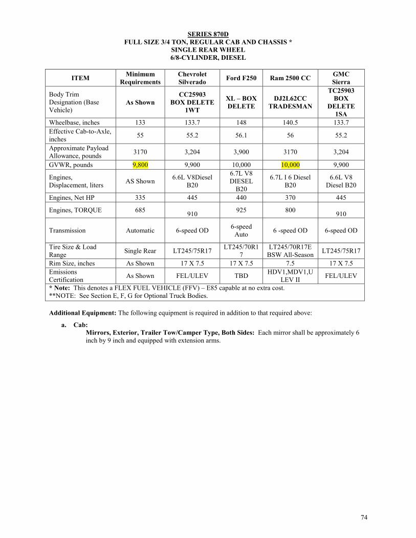
74
SERIES 870D FULL SIZE 3/4 TON, REGULAR CAB AND CHASSIS *
SINGLE REAR WHEEL 6/8-CYLINDER, DIESEL
ITEM Minimum Requirements
Chevrolet Silverado Ford F250 Ram 2500 CC GMC
Sierra
Body Trim Designation (Base Vehicle)
As Shown CC25903
BOX DELETE 1WT
XL – BOX DELETE
DJ2L62CC TRADESMAN
TC25903 BOX
DELETE 1SA
Wheelbase, inches 133 133.7 148 140.5 133.7 Effective Cab-to-Axle, inches 55 55.2 56.1 56 55.2
Approximate Payload Allowance, pounds 3170 3,204 3,900 3170 3,204
GVWR, pounds 9,800 9,900 10,000 10,000 9,900
Engines, Displacement, liters AS Shown 6.6L V8Diesel
B20
6.7L V8 DIESEL
B20
6.7L I 6 Diesel B20
6.6L V8 Diesel B20
Engines, Net HP 335 445 440 370 445
Engines, TORQUE 685 910 925 800
910
Transmission Automatic 6-speed OD 6-speed Auto 6 -speed OD 6-speed OD
Tire Size & Load Range Single Rear LT245/75R17 LT245/70R1
7 LT245/70R17E
BSW All-Season LT245/75R17
Rim Size, inches As Shown 17 X 7.5 17 X 7.5 7.5 17 X 7.5 Emissions Certification As Shown FEL/ULEV TBD HDV1,MDV1,U
LEV II FEL/ULEV
* Note: This denotes a FLEX FUEL VEHICLE (FFV) – E85 capable at no extra cost. **NOTE: See Section E, F, G for Optional Truck Bodies. Additional Equipment: The following equipment is required in addition to that required above:
a. Cab: Mirrors, Exterior, Trailer Tow/Camper Type, Both Sides: Each mirror shall be approximately 6 inch by 9 inch and equipped with extension arms.

75
SERIES 872C
FULL SIZE 3/4 TON REGULAR CAB PICKUP TRUCK LONG BED, SINGLE REAR WHEEL
6/8-CYLINGER, GASOLINE
ITEM Minimum Requirements
Chevrolet Silverado * (GT5) 4.10 Rear Axle
Ratio FFV
RAM 2500
Ford F250 *FFV
GMC Sierra *
(GT5) 4.10 Rear Axle Ratio FFV
Body Trim Designation (Base Vehicle) As Shown CC25903
1WT
DJ2L62 TRADESMA
N XL TC25903
1SA
Wheelbase, inches 133.7 133.7 140.5 141.2 133.7 Approximate Payload Allowance, pounds 3030
3,534 3170 4150 3,534
Length, Overall, inches 224 224.4 231 231.8 224.4 Length, Cargo, inches 97.8 97.8 98.3 98.1 97.8 GVWR, pounds 8,650 9,300 9,000 9,900 9,300
Engines, Displacement, liters As Shown 6.0L V-8
E85*
5.7L V-8 option 6.4L
V8
6.2L V-8 FFV E85*
6.0L V-8 E85*
Engines, Net HP 360 360 383/410 385 360 Engines, TORQUE 380 380 400/429 430 380
Transmission Automatic 6-speed OD 6 -speed OD 6-speed Auto 6-speed OD
Tire Size & Load Range Single Rear LT245/75R17 LT245/70R17E LT245/75R17 LT245/75R17
Rim Size, inches As Shown 17 X 7.5 17 X 7.5 17 X 7.5 17 X 7.5
Emissions Certification As Shown HDV/LEV395 HDV1,MDV1, ULEV II TBD HDV/LEV39
5 * Note: This denotes a FLEX FUEL VEHICLE (FFV) – E85 capable at no extra cost.
Additional Equipment: The following equipment is required in addition to that required above:
a. Cab: Mirrors, Exterior, Trailer Tow/Camper Type, Both Sides: Each mirror shall be approximately 6 inch by 9 inch and equipped with extension arms.

76
SERIES 872D FULL SIZE 3/4 TON REGULAR CAB PICKUP TRUCK
LONG BED, SINGLE REAR WHEEL 6/8-CYLINDER, DIESEL
Additional Equipment: The following equipment is required in addition to that required above:
a. Cab:
Mirrors, Exterior, Trailer Tow/Camper Type, Both Sides: Each mirror shall be approximately 6 inch by 9 inch and equipped with extension arms.
ITEM Minimum Requirements Chevrolet Silverado Ram 2500 Ford F250 GMC Sierra
Body Trim Designation (Base Vehicle)
As Shown CC25903 1WT
DJ2L62 TRADESMAN XL TC25903
1SA
Wheelbase, inches 133.7 133.7 140.5 141.2 133.7 Approximate Payload Allowance, pounds
2420 3,204 2420 3948
3,204
Length, Overall, inches 224.4 224.4 231 231.8 224.4
Length, Cargo, inches 97 97.8 97 98.1 97.8
GVWR, pounds 9000 9300 10,000 9,900 9300 Engines, Displacement, liters
As Shown 6.6L V-8Diesel B20 6.7L I-6 DIESEL
B20
6.7L V-8 DIESEL B20 6.6L V-8 Diesel B20
Engines, Net HP 370 445 370 440 445 Engines, TORQUE 800
910 800 925 910
Transmission Automatic 6-speed OD 6-speed Auto 6-speed Auto 6-speed OD
Tire Size & Load Range Single Rear LT245/75R17 LT245/70R17E
BSW All-Season LT245/75R17 LT245/75R17
Rim Size, inches As Shown 17 X 7.5 7.5 17 X 7.5 17 X 7.5 Emissions Certification As Shown HDV/ULEV2 HDV1,MDV1,U
LEV II TBD HDV/ULEV2
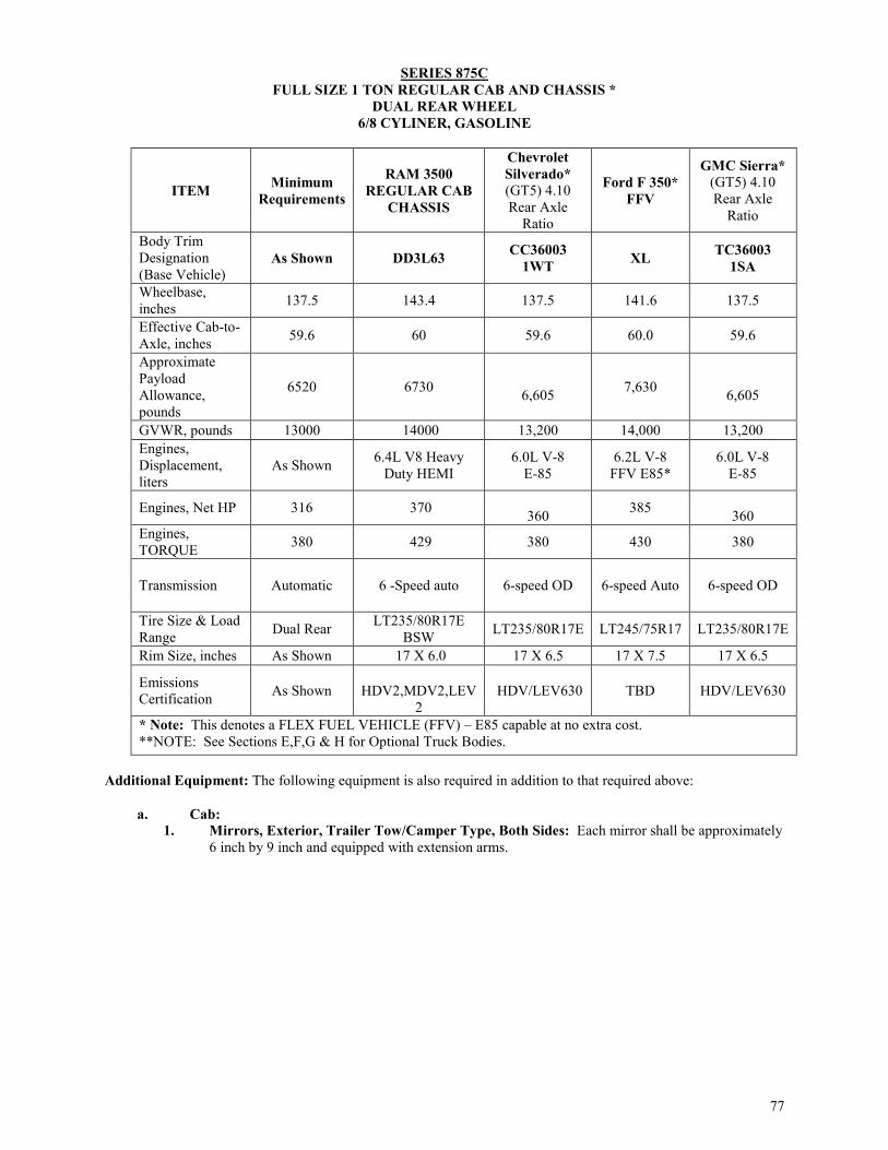
77
SERIES 875C FULL SIZE 1 TON REGULAR CAB AND CHASSIS *
DUAL REAR WHEEL 6/8 CYLINER, GASOLINE
ITEM Minimum Requirements
RAM 3500 REGULAR CAB
CHASSIS
Chevrolet Silverado* (GT5) 4.10 Rear Axle
Ratio
Ford F 350* FFV
GMC Sierra* (GT5) 4.10 Rear Axle
Ratio
Body Trim Designation (Base Vehicle)
As Shown DD3L63 CC36003 1WT XL TC36003
1SA
Wheelbase, inches 137.5 143.4 137.5 141.6 137.5
Effective Cab-to-Axle, inches 59.6 60 59.6 60.0 59.6
Approximate Payload Allowance, pounds
6520 6730 6,605 7,630
6,605
GVWR, pounds 13000 14000 13,200 14,000 13,200 Engines, Displacement, liters
As Shown 6.4L V8 Heavy Duty HEMI
6.0L V-8 E-85
6.2L V-8 FFV E85*
6.0L V-8 E-85
Engines, Net HP 316 370 360 385
360 Engines, TORQUE 380 429 380 430 380
Transmission Automatic 6 -Speed auto 6-speed OD 6-speed Auto 6-speed OD
Tire Size & Load Range Dual Rear LT235/80R17E
BSW LT235/80R17E LT245/75R17 LT235/80R17E
Rim Size, inches As Shown 17 X 6.0 17 X 6.5 17 X 7.5 17 X 6.5
Emissions Certification As Shown
HDV2,MDV2,LEV
2 HDV/LEV630 TBD HDV/LEV630
* Note: This denotes a FLEX FUEL VEHICLE (FFV) – E85 capable at no extra cost. **NOTE: See Sections E,F,G & H for Optional Truck Bodies.
Additional Equipment: The following equipment is also required in addition to that required above:
a. Cab: 1. Mirrors, Exterior, Trailer Tow/Camper Type, Both Sides: Each mirror shall be approximately
6 inch by 9 inch and equipped with extension arms.

78
SERIES 875D
FULL SIZE 1 TON REGULAR CAB AND CHASSIS * DUAL REAR WHEEL
6/8-CYLINDER, DIESEL
ITEM Minimum Requirements
RAM 3500 REGULAR
CAB CHASSIS
Chevrolet Silverado Ford F 350 GMC Sierra
Body Trim Designation (Base Vehicle) As Shown DD3L63 CC36003
1WT XL TC36003 1SA
Wheelbase, inches 137.5 143.4 137.5 141.6 137.5 Effective Cab-to-Axle, inches 59.6 60 59.6 60.0 596
Approximate Payload Allowance, pounds 6248 6730 6605 7,630 6605
GVWR, pounds 13,000 14,000 13,200 14,000 13,200
Engines, Displacement, liters As Shown
6.7L I 6 DIESEL
B20
6.6L V-8 Diesel B20
6.7L V-8 DIESEL B20
6.6L V-8 Diesel B20
Engines, Net HP 300 325 445 440 445 Engines, TORQUE 750 750 910 925 910
Transmission Automatic 6-Speed auto 6-speed OD 6-speed Auto 6-speed OD
Tire Size & Load Range Dual Rear LT235/80R17E
BSW LT235/80R17E LT245/75R17 LT235/80R17E
Rim Size, inches As Shown 17 X 6.0 17 X 6.5 17 X 7.5 17 X 6.5
Emissions Certification As Shown NAS HDV1,
MDV1 ULEV II
HDV/ULEV2 TBD HDV/ULEV2
* Note: This denotes a FLEX FUEL VEHICLE (FFV) – E85 capable at no extra cost. **NOTE: See Sections E,F,G & H for Optional Truck Bodies.
Additional Equipment: The following equipment is also required in addition to that required above:
a. Cab: 1. Mirrors, Exterior, Trailer Tow/Camper Type, Both Sides: Each mirror shall be approximately
6 inch by 9 inch and equipped with extension arms.

79
SERIES 876C FULL SIZE 1 TON REGULAR CAB PICKUP TRUCK
LONG BED, DUAL REAR WHEEL 6/8-CYLINDER, GASOLINE
ITEM Minimum Requirements
Ford F 350* FFV
Chevrolet * (GT5) 4.10 Rear Axle
Ratio FFV
GMC * (GT5) 4.10 Rear Axle
Ratio FFV
RAM 3500 REGULAR CAB 4X2
Body Trim Designation (Base Vehicle)
As Shown XL CC35903 1WT TC35903 1SA D23L62
Tradesman
Wheelbase, inches 133 141.2 133.6 133.6 140.5 Approximate Payload Allowance, pounds
6,690 7,630 7,153 7,153 6,690
Length, Overall, inches 225 231.8 244.4 244.4 231.0
Length, Cargo, inches 97.8 98.1 97.8 97.8 98.3
GVWR, pounds 12,000 14,000 13,500 13,500 12,000 Engines, Displacement, liters As Shown 6.2L V-8 FFV
E85* 6.0L V-8 E85* 6.0L V-8 E85* 6.4L V-8
Engines, Net HP 316 385 360
360 383/410
Engines, TORQUE 380 430 380 380 400/429
Transmission Automatic 6-speed Auto 6 speed OD 6 speed OD 6 speed OD
Tire Size & Load Range Dual Rear LT245/75R17E LT235/80R17E LT235/80R17E LT235/80R17E
Rim Size, inches As Shown 17 X 7.5 17X6.5 6.5 17X6.5
Emissions Certification As Shown TBD HDV/LEV630 HDV/LEV630
NAS HDV1, MDV1 ULEV
II

80
SERIES 876D FULL SIZE 1 TON REGULAR CAB PICKUP TRUCK
LONG BED, DUAL REAR WHEEL 8-CYLINDER, DIESEL
ITEM Minimum Requirements
Chevrolet Silverado (2-Door)
GMC SIERRA (2-Door) Ford F350
RAM 3500 REGULAR CAB 4X2
Body Trim Designation (Base Vehicle)
As Shown CC35903 CC35903 XL D23L62 Tradesman
Wheelbase, inches 133.6 133.6 133.6 141.2 140.5 Approximate Payload Allowance, pounds 6520 6729 6729 7,630 6530
Length, Overall, inches 224.4 224.4 224.4 231.8 231.0
Length, Cargo, inches 97.8 97.8 97.8 98.1 98.3 GVWR, pounds 12600 13025 13025 14,000 14000
Engines, Displacement, liters As Shown 6.6L V8
DIESEL B20 6.6L V8
DIESEL B20
6.7L V-8 DIESEL
B20
6.7L I6 CUMMINS
TURBO DIESEL
Engines, Net HP 370 445 445 440 370 Engines, TORQUE 765 910 910 925 800
Transmission Automatic 6-speed OD 6-speed OD 6-speed Auto 6 speed OD
Tire Size & Load Range Dual Rear LT235/80R17E LT235/80R17E LT245/75R1
7E
LT275/70R18E BSW ALL SEASON
TIRES Rim Size, inches As Shown 6.5 6.5 7.5 8.0 Emissions Certification As Shown HDV/ULEV2 HDV/ULEV2 TBD NAS HDV1,
MDV1 ULEV II * Note: This denotes a FLEX FUEL VEHICLE (FFV) – E85 capable at no extra cost.

81
SERIES 881C FULL SIZE 1 TON CREW CAB PICKUP TRUCK,
6-PASSENGER, LONG BED, SINGLE REAR WHEEL 6/8-CYLINDER, GASOLINE
ITEM Minimum Requirement
Chevrolet Silverado * (GT5) 4.10 Rear Axle
Ratio
Ford F350 * FFV
GMC Sierra * (GT5) 4.10 Rear
Axle Ratio Ram 3500
Body Trim Designation (Base Vehicle)
As Shown CC35943 1WT XL TC35943 1SA D23L92
Wheelbase, inches 167.7 167.7 176.0 167.7 169.5
Approximate Payload Allowance, pounds
3,820 4,124 4,000
4,124 4500
Length, Overall, inches 258.4 258.4 266.2 258.4 259.4
Length, Cargo, inches 97.8 97.8 98.1 97.8 98.3
GVWR, pounds 10500 10,700 11,000 10,700 11000 Engines, Displacement, liters
As Shown 6.0L V-8 E85* 6.2L V-8 FFV E85* 6.0L V-8 E85* 6.4L V-8
Engines, Net HP 316 360 385
360 383/410
Engines, TORQUE 380 380 430 380 400/429
Transmission Automatic 6-speed OD 6-speed Auto 6-speed OD 6-speed OD
Tire Size & Load Range Single Rear LT265/70R18
E TBD LT265/70R18E LT265/70R17E
BSW All-Season
Rim Size, inches As Shown 8.0 TBD 8.0 18X8.0
Emissions Certification As Shown HDV/LEV630 TBD HDV/LEV630
NAS HDV1, MDV1 ULEV
II * Note: This denotes a FLEX FUEL VEHICLE (FFV) – E85 capable at no extra cost.
SERIES 881D

82
FULL SIZE 1 TON CREW CAB PICKUP TRUCK, 6-PASSENGER, LONG BED, SINGLE REAR WHEEL
6/8-CYLINDER, DIESEL
ITEM Minimum Requirement
Chevrolet Silverado
Ford F350
GMC Sierra C30943 Ram 3500
Body Trim Designation (Base Vehicle)
As Shown CC35943 1WT XL TC35943
1SA D23L92
Wheelbase, inches 167.7 167.7 176.0 167.7 169.5 Approximate Payload Allowance, pounds 3,720 3,993 4,000 3,993 4500
Length, Overall, inches 258.4 258.4 266.2 258.4 259.4
Length, Cargo, inches 97.8 97.8 98.1 97.8 98.3 GVWR, pounds 11,000 11,400 11,000 11,400 11,000
Engines, Displacement, liters As Shown 6.6L V-8
Diesel B20
6.7L V-8 DIESEL
B20
6.6L V-8 Diesel B20
6.7L I6 Cummins Turbo Diesel
Engines, Net HP 370 445 440 445 370 Engines, TORQUE 765 910 925 910 800
Transmission Automatic 6-speed OD
6-speed Auto 6-speed OD 6-speed OD
Tire Size & Load Range Single Rear LT265/70R
18E TBD LT265/70R18E
LT265/70R17E BSW All-Season
Rim Size, inches As Shown 18x8.0 TBD 18x8.0 18X8.0 Emissions Certification As Shown HDV/ULE
V2 TBD HDV/ULEV2 NAS HDV1, MDV1 ULEV II
* Note: This denotes a FLEX FUEL VEHICLE (FFV) – E85 capable at no extra cost.

83
SERIES 882C FULL SIZE 1 TON EXTENDED CAB PICKUP TRUCK, 5-PASSENGERS, LONG BED, SINGLE REAR WHEEL
6/8-CYLINDER, GASOLINE
ITEM Minimum Requirement
Chevrolet Silverado * (GT5) 4.10 Rear Axle
Ratio FFV
Ford F350 * FFV
GMC Sierra * (GT5) 4.10 Rear Axle
Ratio FFV
Ram 3500
Body Trim Designation (Base Vehicle) As Shown CC35953
1WT XL TC35953 1SA
Ram 3500 Tradesman
Wheelbase, inches 158 158.1 164.2 158.1 168.9 Approximate Payload Allowance, pounds 3,830
4,246 3,940 4,246
4480
Length, Overall, inches 248.6 248.9 254.4 248.9 259.3 Length, Cargo, inches 97.8 97.8 98.1 97.8 98.3 GVWR, pounds 10,200 10,700 11,000 10,700 11,000 Engines, Displacement, liters As Shown 6.0L V-8 E85* 6.2L V-8
FFV E85* 6.0L V-8 E85* 6.4L V-8
Engines, Net HP 316 360 385
360 383
Engines, TORQUE 380 380 430 380 400
Transmission Automatic 6-speed OD 6-speed Auto 6-speed OD 6-Speed
Tire Size & Load Range Single Rear LT265/70R18E TBD LT265/70R18E LT275/70R18
Rim Size, inches As Shown 18X8.0 TBD 18X8.0
Emissions Certification As Shown HDV/LEV630 TBD HDV/LEV630 * Note: This denotes a FLEX FUEL VEHICLE (FFV) – E85 capable at no extra cost.

84
SERIES 882D FULL SIZE 1 TON EXTENDED CAB PICKUP TRUCK, 5-PASSENGERS, LONG BED, SINGLE REAR WHEEL
6/8-CYLINGER, DIESEL
ITEM Minimum Requirement
Chevrolet Silverado Ford F350 GMC Sierra Ram 3500
Body Trim Designation (Base Vehicle)
As shown CC35953 1WT XL TC35953
1SA
Ram 3500 Tradesman
Diesel Wheelbase, inches 158 158.1 164.2 158.1 168.9 Approximate Payload Allowance, pounds 3,680
3,916 3,940 3,916
4480
Length, Overall, inches 248.6 248.9 254.4 248.9 259.3
Length, Cargo, inches 97.8 97.8 98.1 97.8 98.3 GVWR, pounds 10,800 11,200 11,000 11,200 Engines, Displacement, liters As Shown 6.6L V-8
Diesel B20 6.7L V-8
DIESEL B20 6.6L V-8
Diesel B20 6.7L Diesel
Engines, Net HP 397 445 440
445 370
Engines, TORQUE 765 910 925
910 800
Transmission Automatic 6-speed OD 6-speed Auto 6-speed OD
6-Speed
Tire Size & Load Range Single Rear LT265/70R18E TBD LT265/70R18E
LT275/70R18
Rim Size, inches As Shown 8.0 TBD 8.0 Emissions Certification As Shown HDV/ULEV2 TBD HDV/ULEV2
* Note: This denotes a FLEX FUEL VEHICLE (FFV) – E85 capable at no extra cost.

85
SERIES 886D FULL SIZE 1 TON CREW CAB PICKUP TRUCK
6-PASSENGER, LONG BED, DUAL REAR WHEEL 6/8-CYLINDER, DIESEL
ITEM Minimum Requirements
Chevrolet Silverado Ford F350 GMC Sierra RAM Crew Cab
3500 Body Trim Designation (Base Vehicle) As Shown CC35943
1WT XL TC35943 1SA
D23L92 Tradesman
Wheelbase, inches 167.7 167.7 176.0 167.7 169.5 Approximate Payload Allowance, pounds 5,280 5,281 6,540 5,281 6,190
Length, Overall, inches 248.9 248.9 266.2 248.9 259.4 Length, Cargo, inches 97.8 97.8 98.1 97.8 98.3 GVWR, pounds 11,500 13,025 14,000 13,025 14000
Engines, Displacement, liters As Shown 6.6L V-8
Diesel B20 6.7L V-8
DIESEL B20 6.6L V-8
Diesel B20 6.7 L I 6 Cummins
Diesel
Engines, Net HP 350 445 440 445 370 Engines, TORQUE 800 910 925 910 800
Transmission Automatic 6-speed OD 6-speed Auto 6-speed OD 6 speed auto
Tire Size & Load Range Dual Rear LT235/80R17E LT245/75R17E LT235/80R17E LT235/80R17E
Rim Size, inches As Shown 17 X 6.5 17 X 7 17 X 6.5 6.0
Emissions Certification As Shown HDV/ULEV2 TBD HDV/ULEV2 HDV2,MDV2,LEV 2
* Note: This denotes a FLEX FUEL VEHICLE (FFV) – E85 capable at no extra cost.

86
SERIES 887D FULL SIZE EXTENDED CAB 1 TON PICKUP TRUCK 5-PASSENGERS, LONG BED, DUAL REAR WHEEL
6/8-CYLINGER, DIESEL
ITEM Minimum Requirement
Chevrolet Silverado Ford F350 GMC Sierra
Body Trim Designation (Base Vehicle) CC35953
1WT XL TC35953 1SA
Wheelbase, inches 158 158.2 164.2 158.2 Approximate Payload Allowance, pounds 4,860 5,404 7,200 5,404
Length, Overall, inches 248.6 248.9 254.4 248.9 Length, Cargo, inches 97.8 97.8 98.1 97.8 GVWR, pounds 13,000 13,025 14,000 13,025 Engines, Displacement, liters As Shown 6.6L V-8 B20 6.7L V-8 6.6L V-8 B20
Engines, Net HP 397 445 440 445 Engines, TORQUE 765 910 925 910
Transmission Automatic 6-speed OD 6-speed Auto 6-speed OD
Tire Size & Load Range Single Rear LT235/80R17E LT245/75R17E LT235/80R17E
Rim Size, inches As Shown 17 X 6.8 17 X 7 17 X 6.8 Emissions Certification As Shown HDV/ULEV2 TBD HDV/ULEV2 * Note: This denotes a FLEX FUEL VEHICLE (FFV) – E85 capable at no extra cost.

87
SERIES 888C FULL SIZE 1 TON CREW CAB AND CHASSIS
6-PASSENGER, DUAL REAR WHEEL 6/8-CYLINDER, GASOLINE
Additional Equipment: The following equipment is required in addition to that required above:
a. Cab:
Mirrors, Exterior, Trailer Tow/Camper Type, Both Sides: Each mirror shall be approximately 6 inch by 9 inch and equipped with extension arms.
ITEM Minimum Requirements
RAM 3500 CREW CAB
CHASSIS 4X2
Chevrolet Silverado (GT5) 4.10 Rear Axle
Ratio
Ford F 350 * FFV
GMC Sierra (GT5) 4.10 Rear Axle
Ratio
Body Trim Designation (Base Vehicle)
As Shown DD3L93 TRADESMAN
CC36043 1WT XL TC36043
1SA
Wheelbase, inches 171.5 172.4 171.5 176.0 171.5
Effective Cab-to-Axle, inches 59.1 60 59.1 60.0 59.1
Approximate Payload Allowance, pounds
6020 6119 6,605 6,280 6,605
GVWR, pounds 12,500 13,500 13,200 14,000 13,200 Engines, Displacement, liters
As Shown 6.4L V8 Heavy Duty HEMI 6.0L V-8 6.2L V-8 FFV
E85* 6.0L V-8
Engines, Net HP 316 370 360 385
360 Engines, TORQUE 380 429 380 430 380
Transmission Automatic 6 -Speed auto 6-speed OD 6-speed Auto 6-speed OD
Tire Size & Load Range Dual Rear
LT235/80R17E BSW ALL
SEASON TIRES LT235/80R17e LT245/75R17E LT235/80R17e
Rim Size, inches As Shown 17 X 6.0 17 X 6.5 17 X TBD 17 X 6.5 Emissions Certification As Shown HDV2,MDV2,LEV
2 HDV/LEV630 TBD HDV/LEV630
* Note: This denotes a FLEX FUEL VEHICLE (FFV) – E85 capable at no extra cost. **NOTE: See Sections F,G,H for Optional Truck Bodies.

88
SERIES 888D FULL SIZE 1 TON CREW CAB AND CHASSIS 6-PASSENGER, DUAL REAR WHEEL, DIESEL
6/8-CYLINDER, DIESEL
Additional Equipment: The following equipment is required in addition to that required above:
a. Cab:
Mirrors, Exterior, Trailer Tow/Camper Type, Both Sides: Each mirror shall be approximately 6 inch by 9 inch and equipped with extension arms.
ITEM Minimum Requirements
RAM 3500 CREW CAB
CHASSIS 4X2
Chevrolet Silverado Ford F 350 GMC Sierra
Body Trim Designation (Base Vehicle)
As Shown DD3L93 TRADESMAN
CC36043 1WT XL TC36043
1SA
Wheelbase, inches 171 172.4 171.5 176.0 171.5 Effective Cab-to-Axle, inches 59.1 60 59.1 60.0 59.1
Approximate Payload Allowance, pounds
5,410 5,432 5758 6,280
5758
GVWR, pounds 13,000 14,000 13,200 14,000 13,200 Engines, Displacement, liters As Shown 6.7L I 6 DIESEL
B20 6.6L V-8 Diesel
B20 6.7L V-8
DIESEL B20 6.6L V-8 Diesel
B20
Engines, Net HP 300 325 445 440
445
Engines, TORQUE 660 750 910 925
910
Transmission Automatic 6-Speed auto 6-speed OD 6-speed Auto 6-speed OD
Tire Size & Load Range Dual Rear LT235/80R17E
BSW LT235/80R17E LT245/75R17E LT235/80R17E
Rim Size, inches As Shown 17X6.0 17x6.5 17 X TBD 17x6.5 Emissions Certification As Shown HDV2,MDV2,LEV
2 HDV/ULEV2 TBD HDV/ULEV2
EPA Greenhouse Score As Shown TBD TBD TBD TBD
* Note: This denotes a FLEX FUEL VEHICLE (FFV) – E85 capable at no extra cost. **NOTE: See Sections F,G,H for Optional Truck Bodies.

89
B.7. CUTAWAYS: Unless otherwise specified, all units shall be furnished complete with standard equipment and factory-installed accessories as listed in the manufacturer's printed literature for the models specified herein (See Section A.4.1. and Section B.1.1.). The following items are minimum requirements for the models specified herein, and shall be provided whether shown as optional or standard equipment by the manufacturer. The following are some of those standard features or additional features as listed for these models. Please note any additional requirements following the table for each series number. These additional requirements listed below any table are in addition to, the standard.
7.1. Body:
7.1.1. Bumpers: Manufacturer’s standard front and under-ride rear bumper.
7.2. Chassis: 7.2.1. Air Bags: Required. Manufacturer’s standard to include side curtain/impact airbags if available from manufacturer. 7.2.2. Air Conditioning: Required manufacturer's standard. 7.2.3. Arm Rests, Door-Mounted: Both right and left arm rests are required. 7.2.4. AM/FM Radio: Manufacturer's standard. 7.2.5. Auxiliary Power Outlet: One (1) 12 volt. 7.2.6. Automatic Transmission: Manufacturer’s standard 7.2.7. Brakes: ABS, required, Manufacturer’s standard; front disc, 2- or 4 wheel. 7.2.8. Ground Ratings: As required for the GVWR certified. 7.2.9. Heater and Defroster: Manufacturer’s standard 7.2.10. Jack, Handle, and Lug wrench 7.2.11. Power Steering: Manufacturer’s standard 7.2.12. Seat, Cloth 7.2.13. Shock Absorbers: Front and rear. Manufacturer’s heaviest duty shocks without increase in vehicle trim level. 7.2.14. Sun Visor: Dual. 7.2.15. Tinted Glass: OEM Manufacturer’s Standard Tint. Tinting shall meet Texas DPS regulations. 7.2.16. Spare Wheel: OEM full-size. 7.2.17. Windshield Wipers: Manufacturer’s standard 7.2.18. Bluetooth Wireless Communication: standard for this Series, shall be at no additional cost to Customer. 7.2.19. Back-up Camera: if option is a manufacturer’s standard for this Series, it should be at no
additional cost to Customer. 7.3. KEYS: At no additional cost, each vehicle will be delivered with three (3) ignition/door keys and three (3)
fobs/remote keyless entry/ignition devices.*This applies to ALL vehicles on state contract, unless otherwise specified*
Note: the above are required options on the Series within this section. Ordering entities shall not pay additional cost for the requirement options. Charging a Customer for the above requirements may result in cancellation of award. Note: On specification tables, rim size means tire width, unless otherwise indicated.

90
CUTAWAYS Refer to General Requirements, Preceding Each Group.
SERIES 884C
1 TON CUTAWAY CHASSIS 158 WHEEL BASE, DUAL REAL WHEELS FOR VAN BODY
6/8-CYLINDER, GASOLINE
Additional Equipment: The following equipment is required in addition to that required above:
Note: Additional requirements for Para-transit Vehicles are listed in Section H: Special Equipment
Body
1. Body: Aluminum body or agency approved equal 2. Airbags: Driver and passenger side 3. Air Conditioning: Adequate air conditioning front and rear part of the body. 4. Floor covering: Front vinyl 5. Logistic Track: Inlaid, 12-gauge steel, painted. E-Track or agency approved equal 6. Side Mirrors: trailer towing 7. Cab-access: sliding door in cargo 8. Interior Lights: 12-volt dome light with rear switch 9. Floor: Flat, 2 X 6 Dense Pine ship lapped, formed X-member-16 O.C., 3” X 1-1/2” single lip X-member,
4” I beam long sills, undercoating 10. Lining: 3” Full height plywood lining 11. Interior Lights: Dome light with rear switch, hot wired 12. Bulkhead: 6” setback with or without access 13. Front End: 6-14” radius composite corner wind deflector extruded aluminum front corners with def. rad.
050, smooth 14. Undercoating: Required (Reference Section G, 1.7 Undercoating) 15. Mud Flaps: standard
ITEM Minimum Requirements
Ford E-350 * FFV
Chevrolet Express*
GMC Savana*
Body Trim Designation (Base Vehicle) As Shown E3F CG33803
1WT TG33803
1WT Wheelbase inches 158 158 159 159 Overall Length 261.1 261.1 266.7 266.7 Overall Width 75.4 75.4 79.1 79.1 GVWR, pounds 11500 11,500 12,300 12,300 Engine Displacement, liters As Shown 6.2L V-8 6.0L V-8
E-85 6.0L V-8
E-85 Engine HP 255 255 360 360 Engine Torque lbs -ft 350 350 380 380
Transmission Automatic 5 speed automatic
6 speed automatic
6 speed automatic
Tire size and load range, 6 ea As Shown LT225/75Rx16E
BSW LT
215/85Rx16E LT
215/85Rx16E Rim size, inches 6.5 7 6.5 6.5 Emissions certification As Shown LEV FEL/ULEV FEL/ULEV * Note: This denotes a FLEX FUEL VEHICLE (FFV) – E85 capable at no extra cost.

91
SERIES 885C/885CPT
1 TON CUTAWAY CHASSIS 6/8-CYLINDER, 159 WHEELBASE DUAL REAL WHEELS FOR VAN BODY
GASOLINE Note: 885C: long wheelbase
ITEM Minimum Req. Ford E-450 Chevrolet G4500*
Body Trim Designation (Base Vehicle) As Shown E4F CG33803 2WT
Wheelbase inches 158 158 159 Overall Length 261.2 261.2 266.7 Overall Width 77.7 77.7 79.1 GVWR, pounds 14,200 14,500 14,200 Engine Displacement, liters As Shown 6.8L 6.0L V8
E-85 Engine HP 305 305 360 Engine Torque lbs -ft 373 420 380 Transmission Automatic 5 speed automatic 6 speed auto Tire size and load range, 6 ea As Shown LT225/75Rx16E BSW LT225/75R16E
Rim size, inches 6.5 7 6.5 Emissions certification As Shown LEV FEL/ULEV * Note: This denotes a FLEX FUEL VEHICLE (FFV) – E85 capable at no extra cost. **Diesel not available in long wheelbase
Additional Equipment: The following equipment is required in addition to that required above: Note: Additional requirements for Para-transit Vehicles are listed in Section H and Section I: Special Equipment Body
1. Body: Aluminum body or agency approved equal 2. Airbags: Driver and passenger side 3. Air Conditioning: Adequate air conditioning front and rear part of the body. 4. Floor covering: Front vinyl 5. Logistic Track: Inlaid, 12-gauge steel, painted. E-Track or agency approved equal 6. Side Mirrors: trailer towing 7. Cab-access: sliding door in cargo 8. Interior Lights: 12-volt dome light with rear switch 9. Floor: Flat, 2 X 6 Dense Pine ship-lapped, formed X-member-16 O.C., 3” X 1-1/2” single lip X-
member, 4” I beam long-sills, undercoating 10. Lining: 3/” Full height plywood lining 11. Interior Lights: Dome light with rear switch, hot wired 12. Bulkhead: 6” setback with or without access 13. Front End: 6-14” radius composite corner wind deflector extruded aluminum front corners with def.
rad. 050, smooth 14. Undercoating: Required (Reference Section G, 1.7 Undercoating) 15. Mud Flaps: standard
**NOTE: Options 270 thru 279, and Options 795 thru 797. Please check with the awarded Contractors for
the specific configurations available for this vehicle series. Additional requirements for Para-transit Vehicles are listed in Section H: Special Equipment Body
92
B.8 MEDIUM-DUTY TRUCKS:Unless otherwise specified, all units shall be furnished complete with standard equipment and factory-installedaccessories as listed in the manufacturer’s printed literature for the models specified herein (See Section A.4.1, andSection B.1.1). The following items are minimum requirements for the models specified herein, and shall beprovided whether shown as optional or standard equipment by the manufacturer. The following are some of thosestandard features or additional features as listed for these models. Certain minimum requirements listed below arenot available for Series 929 through 950. Please note any additional requirements following the table for each seriesnumber. These additional requirements listed below are in addition to the following general requirements forMedium Duty Trucks:8.1. Body:
8.1.1 Clearance Lights, Directional, Signals and Reflectors: Shall meet or exceed the requirements of FMVSS No. 108. Armored-type clearance, turn signal lamps, and reflectors are required on cargo bodies. 8.1.2 Rear End Protective Device(s): Medium-duty trucks (except cab and chassis units) shall be equipped with rear and under-ride protection in compliance with Texas Motor Carrier Safety Regulation, Part 393.86. Rear End Protection shall comply with, but not necessarily be limited to, the following specific areas:
8.1.2.1 Clearance from bottom of bumper or protective device(s) and the ground shall not exceed 30 inches with the vehicle empty; 8.1.2.2 Maximum distance between the closest points between bumpers or devices, if more than one is used, shall not exceed 24 inches; 8.1.2.3 Maximum transverse distance from the widest part of the vehicle at the rear to the bumper or device(s) shall not exceed 18 inches; 8.1.2.4 Bumper or device(s) shall be located not more than 24 inches forward of the extreme rear end of the vehicle; and 8.1.2.5 Bumper or device(s) shall be substantially constructed and firmly attached.
8.1.3 MUD FLAPS: Mud flaps shall be installed complete on all vehicles prescribed by law to meet the Department of Public Safety regulation and the following requirements: 8.1.3.1 Mud flaps or truck splash guards, color to be black, anti-sail and anti-splash type,
constructed of rubber or polyethylene, 24 inches wide, 1/4 inch minimum thickness, and of sufficient length to reach within 8 inches of the surface of the highway. They shall be constructed in such a manner so as to prevent sailing and water splashing. They shall have punched mounting holes. If furnished in rubber material, they shall be fully molded and cord-reinforced with metal inserts to prevent sailing and shall weigh a minimum of 18 pounds per pair.
NOTE: NO ADVERTISEMENTS ARE PERMITTED ON MUD FLAPS. 8.2. Cab: Conventional, unless otherwise specified in the invitation for bid. If OEM offers a taller cab option, it is
to be provided as standard at no additional charge. 8.2.1. Air Conditioning: Manufacturer's standard. 8.2.2. Heater and Defroster: Assembly shall be the fresh air type customarily offered as the Standard vehicle manufacturer's accessory and shall be chassis factory installed. Controls shall be mounted on the dashboard. 8.2.3. AM/FM Radio: Manufacturer's standard. 8.2.4. Assist Handles: Installed, one on each side of cab, near the door (except for Series 930). (Outside or Inside). 8.2.5. Horns: Dual electric. 8.2.6. Instruments: Medium-duty trucks shall be equipped with at least the following instruments:
8.2.6.1. Ammeter or voltmeter 8.2.6.2. Coolant temperature gauge 8.2.6.3. Fuel gauge 8.2.6.4. Oil pressure gauge 8.2.6.5. Speedometer 8.2.6.6. Tachometer
8.2.7. REARVIEW MIRRORS, EXTERIOR, LEFT AND RIGHT SIDES (for Medium-duty Trucks only): Mirrors shall have OEM installed metal or plastic frames. These mirrors shall be the type regularly offered as standard original vehicle manufacturer's accessory. Overall face size shall be the largest factory installed available. The mirrors shall have auxiliary convex mirrors (not the stick on type). 8.2.8. Running Boards, External: Furnished anti-skid on both left and right sides of Medium-duty trucks, mounted to the frame (including Series 930), and shall support a minimum 250 pounds.

93
8.2.9. Anti-Skid Steps shall be Cab Length (shall support a minimum of 250 pounds) are acceptable in lieu of Running Boards (Exceptions: TRUCKS FURNISHED WITH STEP TYPE FUEL TANKS (Option Nos. 57 or 58). 8.2.10. Seat Belts, Lap and Shoulder: With 3-point mounting (with retractors for driver and right front passenger and lap belt only for center passenger with bench-type seats). Installed for each passenger space to meet or exceed the requirements of FMVSS Nos. 209 and 210. 8.2.11. Seating with Air Brakes: Air ride, high back driver’s seat and 2-person bench seat. Bench seat shall be furnished with a head rest for each seating position. Head rests shall be height adjustable, if this feature is available from the OEM. 8.2.12. Seating with Hydraulic Brakes: Full width, 3-person bench seat or driver’s seat and 2-person bench seat. Seat shall be furnished with a head rest for each seating position. Head rests shall be height adjustable, if this feature is available from the OEM. 8.2.13. Sun Visors: Dual. 8.2.14. Windshield Wipers (as required by FMVSS No. 104): Electric with intermittent feature windshield washers. 8.2.15. Upholstery: Seat fabric to be cloth or vinyl with cloth inserts. (See Option 258 for all vinyl seats). 8.2.16. Bluetooth Wireless Communication: Manufacturer’s standard, where available. 8.2.17. Power Group – Power locks and windows and Cruise control
8.3. Chassis: 8.3.1. Alternator: **12 volt, minimum 155 ampere for gasoline engines (Series 930D through 990D).
**12 volt, minimum 160 ampere for diesel engines (Series 930D through 990D). 8.3.2. Axle, Rear: Single speed, unless otherwise specified in the RFP. See Paragraph C.9.d.5 for performance requirements. Rear axle dust shields (rock guards) shall be provided on air brake equipped models. 8.3.3. Battery Box Cover, Removable: Cover shall be furnished for any battery or batteries located outside of engine compartment and shall fully enclose the battery or batteries.(Note: May not apply to Hybrid batteries. Not available for Series 929 -950) 8.3.4. Brakes: Shall meet or exceed the requirements of FMVSS No. 105. Air dryer including integral 100-watt heater shall be easily accessible with spin on desiccant cartridge, and automatic moisture ejector on air brake system reservoir(s). EXAMPE: Rockwell WABCO System Saver 1200 or Customer Approved Equal. 8.3.5. Bumper: Front only. 8.3.6. Clutch: Minimum 13-inch single-plate clutch required.
NOTE: MINIMUM 14-INCH SINGLE-PLATE CLUTCH REQUIRED ON DIESEL POWERED TRUCKS (Series 970 through 981 and Series 985 through 990) OR 13-INCH TWO-PLATE CLUTCH MAY BE USED.
8.3.7. Driver’s Side Door: Pocket shall be furnished at driver’s side door for storage of driver’s work/travel logs. Pocket to be a minimum 12 inches long if available. 8.3.8. Magnetic Drain, Magnetic Disc, or Fill Plug: In transmission case and rear axle housing. 8.3.9. Power Steering: Manufacturer's standard. 8.3.10. Shock Absorbers: Front, double action hydraulic. 8.3.11. Springs, Rear: Auxiliary overload type (N/A on Series 930).
NOTE: TWO-STAGE VARIABLE RATE MAIN SPRINGS ALONE ARE UNACCEPTABLE. 8.3.12. Tires and Wheels: Maximum 0.095 inch out-of-round tolerance. Manufacturer's standard. Unless otherwise specified on the IFB, tires and wheels shall be standard OEM approved FULL SIZE, STYLE AND SIZE. Wheels and tires (including spare, where applicable) shall be IDENTICAL for ALL axle positions.
8.3.12.1. Tires: Steel belted radial, tubeless, all-position highway tread (shall meet FMVSS No. 119). Tires shall be at least heat range B rated.
8.3.12.2. Wheel: Disc type, hub piloted. 8.3.12.3. Spare Wheel & Tire: All Medium Duty Trucks (Series 930-959) shall be required to
have full size mounted Spare Wheel & Tire. Tire to be identical in type and size of tire and wheel to those on vehicle. Trucks included in series 960 and up only require matching full size spare wheel, unless otherwise noted.
8.3.13. Transmission: Manual transmission shall be provided as standard equipment on Series 960 through 990, except 986D. Automatic transmission is required on Series 929 through 950 and 986D.

94
8.4. Engine: 8.4.1. Battery: 12 volt, minimum cold cranking performance of 500 amperes for gasoline and 1,000 cold
cranking amperes for diesel at 0 degrees Fahrenheit and 115 minutes reserve capacity at 80 degrees Fahrenheit (Series 930 manufacturer's standard).
8.4.2. Design: Heavy-Duty V8 or V10 gasoline engine with manufacturer's maximum cooling capacity when specified by Series number.
8.4.3. Governor, Engine Speed: Installed and set at manufacturer's maximum recommended RPM. 8.4.4. Mid-range Diesel Engine: Provided when specified by Series Number. 8.4.5. Engine Performance: Transmission and rear axle ratio combination shall provide the following
performance: grade-ability minimum 1.1 percent steady-state at 55 MPH; shall provide minimum 20% start ability from a complete stop (at clutch engagement), based upon full GVWR or GCWR. Maximum road speed 70 MPH, cruise control set at 65 MPH, based on maximum GVWR.
8.4.6. Synthetic lubricants and extended life coolants shall be provided where available. 8.4.7. Long life (Gates Blue Stripe or entity Customer Approved Equal) radiator hoses and silicone water lines
shall also be provided where available.
8.5. Ratings, Complete Units: 8.5.1. Ratings: Each medium-duty truck shall have a Gross Vehicle Weight Rating (GVWR) which meets or
exceeds the Minimum Requirements listed in each table for the respective Series. Each truck shall be equipped with appropriate tires, springs, axle capacities and a chassis designed to transport a combined body and payload allowance which meets or exceeds the minimum Requirement in each respective table. Combined truck and trailer towing weight allowances (Gross Combination Weight Rating - GCWR) are listed for each model in the following tables.
8.6. Cargo Weight: 8.6.1. Base Units: Deduct the driver, passenger, and cargo body weights from the body and payload allowance
shown. The remainder is the cargo weight limit for the standard, base truck.
8.7. KEYS: At no additional cost, each vehicle will be delivered with three (3) ignition/door keys and three (3) fobs/remote keyless entry/ignition devices.*This applies to ALL vehicles on state contract, except Series 960 and above in which it is an option.
* NO EQUIPMENT SHALL BE BOLTED INSIDE THE FRAME FROM A POINT IMMEDIATELY BEHIND THE CAB AND EXTENDING 9 INCHES TOWARD THE REAR OF THE UNIT. IN ADDITION, A CLEAN FRAME RAIL SHALL BE PROVIDED ON THE PASSENGER SIDE FROM THE BACK OF THE CAB TO THE FRONT OF THE REAR SPRING HANGER.
Note: the above are required options on the Series within this section. Ordering entities shall not pay additional cost for the requirement options. Charging a Customer for the above requirements may result in cancellation of award. Note: On specification tables, rim size means tire width, unless otherwise indicated.

95
MEDIUM-DUTY TRUCKS Refer to General Requirements, Preceding Each Group.
SERIES 929D CAB AND CHASSIS *
6/8-CYLINDER, DIESEL 4 X 4
Note: Power locks and windows are required.
ITEM Minimum Requirements
Ford F 450 Crew Cab 4x4
RAM 4500 Crew Cab 4X4
Body Trim Designation Base Vehicle
As Shown XL DP9L93 TRADESMAN
GVWR, pounds 14000 15,000 15000 GCWR, pounds 32,500 33,000 32,500 Front GAWR, pounds 5940 7,580 7000
Rear GAWR, pounds 9,100 12,000 12,000 Approximate Body/Payload Allowance lbs.
5,800 9,000 6,395
Wheelbase, inches 172 179.8 173.4 Cab-to-Axle, inches 56 60 60 Front Axle Capacity, pounds 6000 7,000 7,000
Rear Axle Capacity, pounds 9650 12,000 13,500
Engines, Displacement, liters As Shown 6.7L V-8 B20 6.7 LI6 B20
Engines, HP 300 330 320 Engines, TORQUE 750 750 750
Transmission Automatic 6-speed Auto 6-SPD AUTO AISIN AS69RC HD TRANS
Tire Size & Load Range As Shown 225/70R19.5G
225/70R19.5G ALL POS FT,RR TRACTION
Alternator, amperes ALTERNATOR 200 AMP ALTERNATOR
180 AMP ALTERNATOR

96
SERIES 930D CAB AND CHASSIS
6/8-CYLINDER, DIESEL
ITEM Minimum Requirements International
Ford F 450
RAM 4500 REGULAR CAB
CHASSIS 4X2 Body Trim Designation Base Vehicle
As Shown TerraStar
XL DP4L63 TRADESMAN
GVWR, pounds 16,000 18,000 16,500 16,000 GCWR, pounds 16,500/19,000 26,000 28,700 26,000 Front GAWR, pounds 4,800 7,000 7,000 7,000
Rear GAWR, pounds 11,000 11,000 12,000 12,000
Approximate Body/Payload Allowance lbs
8,326 9,500
9,170 8,326
Wheelbase, inches ** As Shown 134 145 144.4
Cab-to-Axle, inches ** 60 60 60 60
Front Axle Capacity, pounds 7,000 7,000 7,000 7,000
Rear Axle Capacity, pounds 11,000 11,000 12,000 13,500
Heavy-Duty Frame, RBM As Shown TBD TBD TBD
Engines, Displacement, liters As Shown 6.4L V-8
6.7L V-8
6.7L I6 CUMMINS TURBO
DIESEL B20 Engines, HP 300 300 330 325 Engines, TORQUE 610 660 750 750 Governed Speed, RPM As Shown 2,800 TBD 2900
Transmission Automatic Allison 1000 Series
6-speed Auto 6-SPD AUTO AISIN
AS69RC HD TRANS
Tire Size & Load Range As Shown 225/70Rx19.5F 225/70R19.5G 225/70R19.5G ALL
POSITION TIRES
Rim Size, in 6 6 19 X TBD 19.5X6.0 STEEL WHEELS
Alternator, amperes 180 190 220 Amp 180 Stnd/220 opt * NOTE: See Sections E,F,G for Optional Truck Bodies.
Additional Equipment: The following equipment is required in addition to that required above:
a. Body: 1. Rear End Protective Devices: These are not required with standard purchase depending on
clearance level b. Cab:
1. Assist Handles: Not required. 2. Dual Horns: Not required. 3. Rearview Mirror, Camper Style: Units shall be furnished with swing-out type; left and right
side face size shall be the largest factory installed available mirrors and shall be camper style. ***NOTE: For longer cab-to-axle and wheelbase, see Options 33 and 34

97
SERIES 940D CAB AND CHASSIS * CREW CAB
6/8-CYLINDER, DIESEL 4 X 2
ITEM Minimum Requirements Ford F 450 Ram 4500 International
Body Trim Designation (Base Vehicle) As Shown XL 4500 DP4L93
Tradesman TerraStar
GVWR, pounds 16,000 18,000 16500 18,000 GCWR, pounds 26,000 26,000 26,000 26,000 Front GAWR, pounds 5,600 7,500 7,000 7,000 Rear GAWR, pounds 11,000 12,880 12000 11,000 Approximate Body/Payload Allowance, pounds 8,100 10,940 8,108 9,000
Wheelbase, inches ** 172.3 179.8 173.4 203 Cab-to-Axle, inches ** 84 84 84 85 Front Axle Capacity, pounds 7,000 7,500 7,000 7,000 Rear Axle Capacity, pounds 11,000 12,880 12000 11,000 Heavy-Duty Frame, RBM As Shown TBD TBD TBD
Engines, Displacement, liters As Shown 6.7L V-8
6.7L I6 CUMMINS
TURBO DIESEL ENGINE
B20
6.4L V-8
Engines, HP 300 330 325 300 Engines, TORQUE 610 750 750 660 Governed Speed, RPM As Shown TBD 2500 2800
Transmission As Shown 6-speed Auto
6-SPD AUTO AISIN
AS69RC HD TRANS
Allison 1000 Series
Tire Size & Load Range As Shown 225/70R19.5G 225/70R19.5G
ALL POSITION TIRES
P225/70R19.5F
Rim Size, inches As Shown TBD 6 6
Alternator, amperes 180 220 180 Stnd and a 220 opt 190
Additional Equipment: The following equipment is required addition to that required above
a. Body: 1. Rear End Protective Devices: These are not required with standard purchase depending on clearance level
b. Cab: 1. Assist Handles: when available from manufacturer as standard 2. Dual Horns: when available from manufacturer as standard 3. Rearview Mirror, Camper Style: Units shall be furnished with swing-out type; left and right side face size shall be the largest factory installed available mirrors and shall be camper style.
c. Chassis: 1. Shock Absorbers – Heavy duty shock absorbers shall be manufacturer’s maximum capacity

98
SERIES 940G CAB AND CHASSIS * CREW CAB
8 or 10-CYLINDER, GASOLINE 4 X 2
ITEM Minimum Requirements Ram 4500
FORD F450
Body Trim Designation (Base Vehicle)
As Shown 4500 DP4L93 Tradesman
XL
GVWR, pounds 16,000 16,500 18,000 GCWR, pounds 26,000 26,000 26,000 Front GAWR, pounds 5,600 7,000 7,500 Rear GAWR, pounds 12,000 12,000 12,880 Approximate Body/Payload Allowance, pounds
8,400 8,944
10,940
Wheelbase, inches ** 179.8 200 179.8 Cab-to-Axle, inches ** 84 84 84 Front Axle Capacity, pounds 5,600 6,000 7,500
Rear Axle Capacity, pounds 12,000 12,000 12,880
Heavy-Duty Frame, RBM As Shown 980-387 TBD
Engines, Displacement, liters
As Shown Hemi V8 6.2L V8 FFV
Engines, HP 362 366 385
Engines, TORQUE As Shown 429 430 Governed Speed, RPM As Shown TBD TBD
Transmission Automatic 6-SPD AUTO AISIN AS69RC HD TRANS
6-speed Auto
Tire Size & Load Range As Shown
225/70R19.5G ALL POSITION TIRES
225/70R19.5G
Rim Size, inches 6 6 TBD Alternator, amperes 155 155 200
Additional Equipment: The following equipment is required addition to that required above
a. Body: 1. Rear End Protective Devices: These are not required with standard purchase depending on clearance level
b. Cab: 1. Assist Handles: when available from manufacturer as standard 2. Dual Horns: when available from manufacturer as standard 3. Rearview Mirror, Camper Style: Units shall be furnished with swing-out type; left and right side face size shall be the largest factory installed available mirrors and shall be camper style.
d. Chassis: 2. Shock Absorbers – Heavy duty shock absorbers shall be manufacturer’s maximum capacity
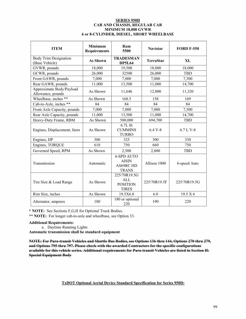
99
SERIES 950D CAB AND CHASSIS, REGULAR CAB
MINIMUM 18,000 GVWR 6 or 8-CYLINDER, DIESEL, SHORT WHEELBASE
ITEM Minimum Requirements
Ram 5500 Navistar FORD F-550
Body Trim Designation (Base Vehicle) As Shown TRADESMAN
DP5L64 TerraStar XL
GVWR, pounds 18,000 19,500 18,000 18,000 GCWR, pounds 26,000 32500 26,000 TBD Front GAWR, pounds 7,000 7,000 7,000 7,500 Rear GAWR, pounds 11,000 13,500 11,000 14,700 Approximate Body/Payload Allowance, pounds As Shown 11,646 12,000 11,320
Wheelbase, inches ** As Shown 168.5 158 169 Cab-to-Axle, inches ** 84 84 84 84 Front Axle Capacity, pounds 7,000 7,000 7,000 7,500 Rear Axle Capacity, pounds 11,000 13,500 11,000 14,700 Heavy-Duty Frame, RBM As Shown 500,000 694,700 TBD
Engines, Displacement, liters As Shown 6.7L I6
CUMMINS TURBO
6.4 V-8 6.7 L V-8
Engines, HP 300 325 300 330 Engines, TORQUE 610 750 660 750 Governed Speed, RPM As Shown 2,500 2,800 TBD
Transmission Automatic
6-SPD AUTO AISIN
AS69RC HD TRANS
Allison 1000 6-speed Auto
Tire Size & Load Range As Shown
225/70R19.5G ALL
POSITION TIRES
225/70R19.5F 225/70R19.5G
Rim Size, inches As Shown 19.5X6.0 6.0 19.5 X 6
Alternator, amperes 180 180 or optional 220 190 220
Additional Requirements: a. Daytime Running Lights Automatic transmission shall be standard equipment NOTE: For Para-transit Vehicles and Shuttle Bus Bodies, see Options 136 thru 144, Options 270 thru 279, and Options 795 thru 797. Please check with the awarded Contractors for the specific configurations available for this vehicle series. Additional requirements for Para-transit Vehicles are listed in Section H: Special Equipment Body
TxDOT Optional Aerial Device Standard Specification for Series 950D:
* NOTE: See Sections F,G,H for Optional Truck Bodies. ** NOTE: For longer cab-to-axle and wheelbase, see Option 33.

100
AERIAL DEVICE, TRUCK-MOUNTED, ARTICULATED OR TELESCOPING 28, 30, 32, AND 35 FOOT
1. SCOPE: This specification describes a 28, 30, 32, and 35 foot articulated or telescoping truck mounted,
insulated aerial device. Unit shall safely hydraulically lift and rotate personnel to the heights specified in the solicitation. The unit shall be used for such things as overhead sign maintenance, safety lighting maintenance, traffic signal maintenance, etc. The specification is inclusive of telescoping, articulating, and articulating over center type booms. If a particular boom type is required, it will be specified on the solicitation. The aerial device shall be complete, assembled, mounted, serviced, tested and certified in accordance with the current American National Standard Vehicle-Mounted Elevating and Rotating Aerial Devices ANSI/SIA A92.2 on the vehicle specified on the solicitation. Unit furnished to these specifications shall meet or exceed all the following requirements. EXAMPLES: Altec AT 30G and AT35-G Versalift TEL-29-IH, T-34-I,T3100-I or equal NOTICE TO RESPONDENT: Any example shown is listed to show type and class of equipment desired. Respondent is cautioned to read the specification carefully, as there may be special requirements not commonly offered by the equipment manufacturer. DO NOT ASSUME STANDARD EQUIPMENT MEETS ALL OF THE DETAILED SPECIFICATION REQUIREMENTS MERELY BECAUSE IT IS LISTED AS AN EXAMPLE. Respondent is cautioned that any unit delivered to the FOB point that does not meet specifications in every aspect will not be accepted.
2. ANSI/SIA: A unit meeting this specification shall be in compliance with the current "American National Standard for Vehicle-Mounted Elevating and Rotating Aerial Devices, "ANSI/SIA A92.2. Requirements contained in this specification that were extracted from the ANSI/SIA publication will be cross-referenced with the initials "ANSI/SIA" and the appropriate paragraph numbers for the respondent’s convenience. The Contractor shall remain responsible for ensuring all ANSI/SIA requirements are met.
3. DEVICE REQUIREMENTS
3.1. PLATFORM HEIGHT (ANSI/SIA A92.2-2015): The platform height shall be a minimum 28, 30, 32 or 35 feet as specified on the solicitation, measured at maximum elevation of the device, from the floor of the bucket to the ground with the device mounted on the vehicle as specified on the solicitation. Extensions, spacers, inserts, etc. shall not be installed on this aerial device solely for the purpose of meeting height requirements. Any other type spacer that is a standard feature of the design of the aerial device shall not exceed eight inches in height.
3.2. REACH (ANSI/SIA A92.2 Section 6.2.2.4): The reach of the device shall be measured from the centerline of the pedestal to the outer edge of the bucket. Reach shall be as follows:
3.2.1. A 28-foot unit shall have a reach of at least 17 feet at a platform height of 14 feet.
3.2.2. A 30-foot unit shall have a reach of at least 18 feet at a platform height of 16 feet.
3.2.3. A 32-foot unit shall have a reach of at least 19 feet at a platform height of 18 feet.
3.2.4. A 35-foot unit shall have a reach of at least 21 feet at a platform height of 16 feet.
3.3. CAPACITY (ANSI/SIA A92.2 Section 6.2.2.2 Type 1): The rated capacity of the platform shall be a minimum 300 pounds, unless otherwise specified on the solicitation. The rated capacity shall be designated with the boom(s) extended to the position of maximum overturning moment attainable throughout full rotation of its pedestal.
4. STABILITY REQUIREMENT
4.1. LEVEL GROUND (ANSI/SIA 4.5.1 - 4.5.3): The device, when mounted on the truck as specified, shall sustain a static load one and one-half times its rated load capacity, in every position in which the load can be placed within the definition of the specific configuration, when the unit is on a firm and level surface. If stability-assist equipment such as outriggers or a torsion bar is part of the definition of the configuration, they shall be utilized according to the manufacturer’s instruction for the purpose of determining whether the unit meets the stability requirements. If outriggers are provided, the outrigger spread at full extension shall not exceed 144 inches.

101
4.2. SLOPES (ANSI/SIA 4.5.2 and 4.5.3): The device, when mounted on the truck as specified, shall sustain a static load one and one-third times its rated load capacity, in every position in which the load can be placed within the definition of the specific configuration when the vehicle is on a slope of five degrees downward in the direction most likely to cause overturning. If stability assist equipment such as outriggers or a torsion bar is part of the definition of the configuration, they shall be utilized according to the manufacturer’s instruction for the purpose of determining whether the unit meets the stability requirements. If outriggers are provided, the outrigger spread at full extension shall not exceed 144 inches.
4.3. STABILITY CERTIFICATION (ANSI/SIA - SECTION 4): Contractor shall provide the receiving district with a certified report of the stability tests. The stability tests shall include the capacity with stability-assist equipment in use.
4.4. TORSION BAR(S): Unit shall be equipped with torsion bar stabilizers mounted to the chassis to prevent excessive tipping and spring compression with the device in working position to the side of the truck. Torsion bars installed shall be of the quantity, size and type recommended by the manufacturer of the aerial device. Unit shall be equipped with torsion bars only if recommended by the manufacturer.
5. GROUNDING REQUIREMENTS (ANSI/SIA SECTION 5): The truck cab, chassis, bed and boom(s) shall be a grounded unit. All necessary components for grounding of the unit during work operations shall include, but not be limited to, the following:
5.1. Minimum 50 feet of No. 2 copper stranded grounding cable, 600 volt yellow cover with one end grounded to the cable reel and the free end shall have a positive clamp for attaching to the copper bronze ground rod.
5.2. A cable reel for the cable mounted in a position so as not to interfere with the normal operations of the unit. If Contractor’s mounting location for reel interferes with the unit’s storage area, Contractor shall coordinate with TxDOT for final mounting location. The reel shall not be mounted where it will interfere with a trailer hitch installation.
5.3. Grounding cable fastening method, as a minimum, the cable and cable reel shall be grounded to units frame. Provide one or two positive screw-on ground clamps to the free end of grounding cable. Alternate means of grounding the cable shall be coordinated with TxDOT
5.4. Provide a minimum 9/16 inch diameter x six foot long copper bronze grounding rod.
6. PERSONNEL BUCKET: Unit shall be equipped with a fiberglass bucket with door. Bucket shall:
6.1. Be of fiberglass construction and have a walk-in door with safety chain, facing curbside.
6.2. Have decal(s) with max weight capacity in black lettering, measuring a minimum 6 inches tall, applied to the exterior of bucket door.
6.3. Have an insulated positive type self-leveling system that will cause the bucket to automatically assume and hold a level position as the boom elevation varies. Gravity or pendulum type leveling is not acceptable.
6.4. Be equipped with a hydraulic “bucket dump” feature for the removal of water and to aid in the removal of an injured person.
6.5. Be minimum 24” inches wide x 42” inches long x 42” inches deep.
6.6. Be equipped with one OSHA-approved, fall-arrest safety harness and a 48” inch decelerating or shock absorbing type lanyard. An attachment point shall be provided for attaching safety harness lanyards to the aerial device.
EXAMPLE: Klein Tools Fall Arrest Safety Harness Model #87020, Medium: 36 – 44 inches, Elk River Inc. Shock Absorbing Lanyard, P/N 35324, 1 inch X 4 feet, NoPac, or equal
6.7. Be equipped with one fiberglass tool tray of size normally provided by the manufacturer.
6.8. Be equipped with hydraulic rotators to allow 180 degree rotation of the bucket. Controls shall be located

102
at the bucket.
6.9. Have red and white chevrons on rear facing side of bucket made of 8” wide 3M reflective DOT approved tape. Bottom chevron shall be red and alternate colors moving upwards.
6.10. Be equipped with a removable vinyl cover that stretches over the bucket lip and prevents water from entering the bucket.
7. BOOM AND PEDESTAL: Unit shall be equipped with either an articulated-elbow or telescoping type boomdesign unless specified otherwise.
7.1. LOWER BOOM: The lower boom or section shall be constructed of steel.
7.2. UPPER BOOM: (ANSI/SIA - SECTION 5): Upper boom or section shall be constructed of fiberglassand shall be electrically insulated and certified to the requirements of the current ANSI/SIA A92.2, Category "C".
NOTE: INSULATION CERTIFICATION (ANSI/SIA - SECTION 5): Contractor shall provide the receiving district with a certified report of the insulation tests required by ANSI/SIA A92.2 when delivery is made.
7.3. CENTER SECTION: Center section of a three-stage telescoping type boom shall be of steel or fiberglass construction.
7.4. PEDESTAL: The pedestal furnished shall be the standard design for the aerial device model awarded. Pedestal shall be mounted in the manner recommended by the manufacturer. Mounting shall provide for a minimum of overhang of the device on both the front and rear of the truck.
7.5. BOOM ROTATION: The device shall be able to rotate continuous 360 degrees in either direction.
8. HYDRAULIC SYSTEM (ANSI/SIA 4.6 - 4.8): Power for elevation, extension, rotation and related movementsof the device shall be by means of a complete hydraulic system.
8.1. An SAE power take-off assembly on the truck transmission shall power the hydraulic pump(s).
8.2. System shall include all necessary hoses, fittings, connectors, reservoir, filter and other items necessary for operation.
8.3. Hydraulic system shall be equipped with the appropriate devices to prevent free and unrestricted motion of the aerial device including boom(s) and outriggers and bucket leveling system, in the event of hydraulic failure.
8.3.1. The unit shall be equipped with an emergency power system to provide back-up power in case the truck engine fails and the hydraulic system is inoperable. The system shall consist of a 12-volt DC electrical pump, which operates off the truck battery to safely lower the bucket and operator. Controls shall be at the bucket and pedestal.
8.3.2. The aerial device shall have easily accessible reducing valves to bleed off hydraulic pressure and safely lower the bucket and pedestal in the event of the failure of both the truck engine and electrical system.
9. CONTROLS (ANSI/SIA 4.3.1 - 4.3.6): Controls shall be feather type, furnished at the bucket and pedestal forcontrolling all movements of the device.
9.1. Pedestal controls shall override the bucket controls and provide full metering for gradual movement ofall functions.
9.2. Controls for the hydraulic “bucket dump” feature shall be at the pedestal.
9.3. Bucket control lines shall be permanently installed in the interior of the boom.
9.3.1. Bucket and pedestal controls shall be insulated and provide full metering for gradual movement of all functions.
9.3.2. Bucket and pedestal controls shall automatically assume a neutral or off position when released by the operator to automatically stop the motion of the device.
9.4. Insulated return to neutral type controls to start and stop the truck engine shall be provided at the bucket.

103
An engine throttle control shall also be provided if the aerial device is equipped with an open-center type hydraulic system.
10. INSTALLED EQUIPMENT ELECTRICAL SYSTEM
10.1. Unless provided by Chassis OEM, Contractor shall furnish a Power Distribution Center (PDC) independent of the chassis OEM electrical system, for all added equipment electrical wiring. PDC shall include as a minimum:
10.1.1. Covered junction box furnishing individual protected circuits for all non-chassis equipment ordered.
10.1.2. Excess capacity for a minimum of two additional circuits to be added at a later date.
10.1.3. A compatible switch panel with indicator light.
10.2. Contractor shall furnish a separate, waterproof, minimum 70 amp manual reset circuit breaker to be located between the battery and the PDC for the added equipment. The circuit breakers manual reset function shall allow isolation of added equipment wiring from the OEM electrical system.
10.3. Contractor shall furnish a chassis with an OEM installed equipment wiring system. Chassis manufacturer shall provide convenient access points for fused power to allow installation of body accessories. Under no circumstances is added equipment to be wired into the main chassis fuse box.
10.4. All electrical wiring shall be insulated and enclosed in a fibrous loom, plastic loom or flexible conduit for protection from external damage and short circuits. Wiring shall be securely fastened at sufficient intervals to prevent sagging and insure clearance of mechanical parts. Routing of the wiring through the sub-frame, deck, etc. shall not interfere with the normal operation and use or present a safety hazard. A sealed, splice-free modular wiring harness is acceptable. Rubber grommets shall be used wherever wires or harness pass through metal.
10.5. Contractor shall furnish a Pure Sine Wave, Minimum 3000 Watt inverter. Inverter shall be mounted in one of the tool boxes or body compartments. Inverter shall have a circuit hard wired to an electrical outlet mounted curbside on the rear tail shelf. Contractor shall coordinate with TxDOT for final mounting locations.
10.6. Contractor shall provide a back-up camera system containing a cab mounted, minimum 7” inch color display. Camera will be mounted on rear hitch plate. Contractor shall coordinate with TxDOT for final mounting locations of monitor and camera.
EXAMPLE: Example Model: Zone Defense ZD.323.1.CH or equal.
11. MARKINGS (ANSI/SIA 4.10 - 4.10.2 and 6.5 - 6.5.4): The aerial device shall include, but not be limited to, the following legible, permanent and readily visible markings in English or universally recognized symbols:
11.1. IDENTIFICATION MARKINGS: The manufacturer shall install markings indicating the following: make, model, insulated or non-insulated, qualification voltage, date of test, serial number, rated load capacity, buck height (to bottom of bucket), and aerial device system pressure or aerial device system voltage, or both.
11.2. OPERATION MARKINGS: The manufacturer shall install markings on the equipment describing the function of each control.
11.3. INSTRUCTION MARKINGS: The manufacturer shall install markings that indicate hazards inherent in the operation of an aerial device and those hazards for which the aerial device does not provide protection. These markings shall include, but not be limited to:

104
11.3.1. Electrical hazard markings cautioning that the aerial device does not provide protection to the operator from contact with or proximity to an electrically charged conductor when the operator is in contact with or in proximity to another conductor. These markings shall include weather-resistant placards, decals, or both, of not less than 5 inches by 7 inches with a yellow background and black lettering reading as follows: "WARNING - UNLAWFUL TO OPERATE THIS EQUIPMENT WITHIN TEN FEET OF HIGH VOLTAGE LINES." The markings shall be legible at a distance of 12 feet and placed as follows:
11.3.1.1. Within the equipment readily visible to the operator(s) at each control station.
11.3.1.2. On the outside of equipment in such number and location as to be readily visible to other persons engaged in the work operations from all sides of the vehicle.
11.3.2. Electrical hazard markings cautioning that the aerial device, when working on or in proximity to energized conductors, shall be considered energized, and that contact with the aerial device or vehicle under those conditions may cause serious injury. These markings shall also warn that there is no protection from phase-to-phase situations.
11.3.3. Hazards that may result from improper or non-prescribed use of the aerial device.
11.3.4. Information concerning the use and load rating of the equipment for material handling.
11.3.5. Information related to operator cautions.
11.3.6. Bucket capacities shall be permanently marked in six inch high black letters on the outside of the bucket door.
12. TRUCK BODY: The truck shall be equipped with a utility body designed for general utility work and suitable for mounting on a truck chassis having dual rear wheels and meeting the current ANSI/SIA Sections 6 and 7. The body shall be treated for resistance to rust and corrosion prior to being painted. The utility body requirements, which follow, are listed for an 84-inch and 102-inch cab-to-axle truck chassis units. This specification utility body shall be provided unless specified otherwise on the solicitation.
NOTE: Mounted equipment shall not be welded to the vehicle frame at any point between the front of the front spring hanger and the rear of the rear spring hanger. Also, all holes for bolting shall be drilled in the accepted manner and the burning of the holes shall not be acceptable. Further, no holes shall be drilled in top or bottom flange of truck frame unless drilling is confined to the section behind the rearmost attachment of the rear spring hangers or for preformed factory-made frame rail bolt holes for subsequent body installation. Welding or torch cutting shall be confined to "boxing" the rear end of truck frame. All such work shall be confined to area behind rear spring hangers. Chassis frame rivets shall not be removed or cut flush with frame. Welding to vehicle frame in violation of these requirements shall be grounds for rejection of the unit. 84-Inch C.A. 108-Inch C.A.
12.1. BODY LENGTH: 132 157
12.2. BODY WIDTH: 94 fixed 94 fixed
12.3. BODY HEIGHT: 40 40
12.4. SIDE COMPARTMENT DEPTH: 18 or 20 18 or 20
12.5. INSIDE BODY FLOOR WIDTH: 54 or 58 54 or 58
NOTE: Utility body configuration dimensions are in inches, compartment width dimensions are approximate, with a range of tolerance of ± 3 inches.
12.6. The body shall be fabricated from cold-rolled automotive steel and be all electrically welded. Floor shall be covered with safety tread plate and have drain holes. The entire structure shall be sealed to prevent water from entering the compartments. The entire exposed underside of the utility body shall be completely and thoroughly undercoated without skips, voids, or thin places with high quality asphalt base underbody coating conforming to Federal Specification TT-C520-B.

105
EXAMPLE: Lion Nokorode Emulsion 331 manufactured by Lion Oil Company or equal
12.7. Both sides shall be equipped with two full-height vertical compartments if body is for an 84-inch cab-to-axle or three full-height vertical compartments if body is for a 108 inch cab-to-axle. These compartments shall be forward of the rear wheels, each approximately 28 inches wide for 84 inch cab-to-axle and each approximately 24 inches wide for 108 inch cab-to-axle.
12.8. Both sides shall be equipped with a minimum of one full-height vertical compartment behind the rear wheels approximately 22 inches wide.
12.9. Both sides shall be equipped with one horizontal compartment over the rear wheels approximately 54 inches wide.
12.10. Compartment doors shall have recessed handles with slam-action latches and all locks keyed alike. Each door shall be equipped with a stay to prevent the door from opening into other doors or body components.
12.11. Each vertical compartment shall have two adjustable shelves and the horizontal compartments shall have material drawers with dividers.
12.12. All body compartments shall be provided with L.E.D. light strips that shall run the length of each compartment. The light strips shall be activated with door switches that will be wired to an in-cab master battery switch.
12.13. Both the 84 inch and the 108 inch cab-to-axle body shall have a 42 inch tailshelf added on the rear of the bed at the same height and extend across the full width of the bed to serve as an extended work shelf. This tailshelf shall provide a step access point on the curb side. The access point area needs 2 steps in body and one non-rigid step under body and a minimum 18" wide. Welding to vehicle frame in violation of these requirements shall be grounds for rejection of this unit.
12.14. A bumper measuring as wide as the platform shall be a maximum 23 inches from the ground and a
minimum 16 inches deep shall be provided. Bumper shall be a two section type, recessed to allow for trailer tow hitch.
12.15. A tread plate of minimum 1/8-inch diamond pattern steel plate shall be provided on the top of both side compartments.
12.16. Vertical grab handles approximately 20 inches long shall be provided at top rear on each side.
12.17. A boom rest, if necessary, shall be located and securely mounted to the manufacturer's recommendation, to hold the boom in the lowered position while traveling. RESPONDENT & CONTRACTOR NOTE: THE CONTRACTOR SHALL COORDINATE FINAL CONFIGURATION (BODY, BUCKET MOUNTING AND OUTRIGGERS TYPE AND LOCATION), WITH THE RECEIVING DISTRICT BY SUBMITTING APPROVAL DRAWINGS, BEFORE FABRICATION OF THE UNIT. THE REQUIREMENTS LISTED ABOVE AND ON THE SOLICITATION, MAY BE EXCEEDED ONLY AT NO COST TO TxDOT.
13. LIGHTING: The lighting arrangement on the truck and body shall be in accordance with Texas Traffic Laws.
13.1 Quantity, type, mounting and wiring requirements shall be as specified in the current version of the State of Texas, Automobiles and Trucks, Texas Specification No. 071-072-AT.
13.2 All body lighting shall be LED, including side markers, stop lights, reverse lights and turn signals.
13.3 Contractor shall use the following specification for emergency lighting.
13.3.1 Whelen Mini LFL Liberty lightbar, Amber, P/N IT9AAAAP, with four additional Amber light heads, P/N SLDAA mounted passenger side.
13.3.2 Whelen Mini LFL Liberty lightbar, blue, P/N IT9BBBBP, with four additional blue light heads, P/N SLDBB mounted driver side.
13.3.3 Whelen M Series amber, P/N M7A mounted passenger side rear tool box
106
13.3.4 Whelen LIN3 amber, P/N RSA02CCR mounted passenger side tailshelf.
13.3.5 Whelen M Series blue, P/N M7B mounted driver side rear tool box.
13.3.6 Whelen LIN3 amber, P/N RSA02CCR mounted driver side tailshelf.
Note: The manufacturer and model numbers shown above are examples only. An equivalent product from other manufacturers may be considered by the Customer.
13.4 An arrow stick, Amber colored, minimum 46.5” inches long with control head mounted on rear tail shelf.
EXAMPLE: Whelen, Traffic Advisor, Model #TAM85 or equal
13.5 Dual motorized spot lights, minimum 400,000 candle power that are wirelessly operated from within the chassis cab and via a wireless remote control shall be furnished and mounted to chassis cab.
EXAMPLE: GOLIGHT Model #2007 Or equal
14. HOURMETERS: Provide two hourmeters, as follows:
14.1. One standard OEM in-dash hourmeter, monitoring the truck engine.
14.2. One electric quartz type, shock proof, totally sealed case hourmeter, with readout up to 9,999.9 hours for monitoring the PTO. EXAMPLES: Hobbs Three Screw Model 85097-02 Hobbs Flush Mounted Model 85093-03 or equal
15. PAINTING: The unit shall be painted with a manufacturer's standard lead free white color, except for glass, rubber and those metallic accessories or fixtures constructed of rust-resistant or plated material not normally painted.
16. MANUAL(S): Two original copies of aerial device manuals as described in Para. 6.4. and 6.10. of the current ANSI/SIA A92.2 shall be delivered with each unit. These manuals shall include, but not be limited to, an illustrated parts book, operator's manual, service and safety manuals. These also shall include, at minimum, all appropriate manuals for the device hydraulic system, controls and electrical system. Also, an original chassis manual(s) containing illustrated parts list(s) and operating and service instructions for the unit and engine(s) shall be delivered with each unit.
16.1. Additionally, two complete sets of original aerial device wiring and hydraulic schematics shall be delivered with each unit. All schematics shall be clear, legible and indicate the location of each component. Hydraulic schematics shall include the diameter and length of each hose and the manufacturer and part number of each fitting.
16.2. The original manuals and schematics supplied shall provide complete and comprehensive information on all equipment, equipment components and accessories, as supplied to comply with this specification. If changes, modifications, additions or alterations of any kind are made on the equipment, the Contractor shall provide blueprints, line drawings and descriptive text sufficient to allow one of average skill in general mechanics to diagnose, repair and maintain the equipment and all components.
16.3. On equipment assembled from manufactured components, original parts manuals shall show the manufacturer of each part and all cross referencing between the Contractor and the manufacturers.
16.4. The original operator's manual shall include detailed instructions on the proper method of operation of the unit, load and stability requirements, and electrical safety instructions, to include proper use of the grounding kit. Necessary warnings and safety precautions shall be included.
16.5. The following additional information shall be provided by the Contractor at time of delivery if not included in the manual required above.
16.5.1. Manufacturer’s recommended service and preventive maintenance intervals.
16.5.2. Recommended fluids, lubricants and their SAE or API equivalents.

107
NOTE: Districts must retain these manuals until the unit is disposed of. Upon sale of the unit, these manuals must be furnished to the purchaser (Ref. ANSI/SIA 8.7).
17. INSTRUCTION ON SAFETY, OPERATION, AND MAINTENANCE (ANSI/SIA 7.8 AND 8.12): The Contractor shall provide the services of a competent factory-trained technician thoroughly trained in the use and operation of the unit to TxDOT for a minimum of eight hours of instruction on safety, operation and preventive maintenance of the unit, as required by ANSI/SIA 8.12, after the machine has been delivered and is ready for operation but prior to payment. The instruction shall include a full demonstration of all unit functions on the unit(s) delivered. The electrical safety instruction shall include, but not be limited to, proper grounding procedures for the vehicle. Instruction shall identify potentially hazardous situations that can occur when working in the vicinity of high voltage lines, and how these situations can be prevented or reduced.
17.1. LESSON PLAN: The Contractor shall furnish two original copies of the unit manufacturer’s approved lesson plan for the instructional training required, within 30 days after award of the purchase order. One copy shall be furnished to the receiving TxDOT District (F.O.B. point) attention District Equipment Supervisor shown on the face of the purchase order. The lesson plans shall be as detailed as possible, covering all safety and pre-operational (daily) inspection and maintenance procedures necessary to adequately prepare an operator prior to using the unit in routine work. Additionally, as a minimum, the instruction shall include weekly, monthly, three-month, and six-month pre-operational inspections and maintenance procedures. The lesson plan may be taken from the operator’s manual, provided all necessary information is included.
17.2. MAINTENANCE SCHEDULE: The Contractor shall furnish a separate list of manufacturers recommended scheduled maintenance items and shall cover this list in detail with district personnel as designated by the district equipment administrator.
18. INSPECTIONS, CERTIFICATIONS, AND SAFETY EQUIPMENT
18.1. SAFETY INSPECTION: The Contractor shall have the unit(s) inspected in accordance with either the United States Department of Transportation or the State of Texas motor vehicle laws [as indicated by the Gross Vehicle Weight Rating of the unit(s) cab and chassis]. A certified inspection station shall conduct the inspection and the unit shall have the inspection certificate properly affixed at time of delivery.
18.2. AXLE ALIGNMENT: After the aerial device and body are mounted on the chassis and all additional equipment is installed, the axles of the completely assembled unit shall be properly aligned in accordance with the chassis manufacturer’s recommended specifications for the caster, camber, toe and tracking. The alignment shall include allowances for a minimum of 800 pounds of payload and 400 pounds in the cab for the operator and the passenger. Documentation recording the date of the axle alignment shall be furnished.
18.3. UNIT WEIGHTS: Aerial unit shall be delivered with weight tickets from a certified scale. Weights provided shall include the front axle weight and combined gross weight.
18.4. ANSI CERTIFICATION AND DOCUMENTATION: The aerial device described above shall be complete, assembled, mounted, serviced, tested, and certified on the vehicle described on the solicitation. Complete unit(s) shall be furnished. A unit shall be composed of an aerial device mounted on a truck chassis and shall include any additional options or special equipment specified. The aerial device shall be delivered in full compliance with all applicable ANSI and OSHA standards, rules, and regulations. A corresponding inspection sticker shall be affixed. A test report noting any discrepancies identified along with the corrective action taken and the date performed, and stating the results of a dielectric test and stability test performed on the delivered unit will be provided. If there are any repairs made at the time of inspection, a completed work order describing the repair shall be included with the report. All paperwork shall be signed and dated by a certified aerial device inspector.
18.5. MANUFACTURER’S STATEMENT OF ORIGIN (MSO) AND LINE SETTING SHEET: A MSO and line setting sheet covering the components of each cab and chassis provided shall be furnished by the Contractor. Cusomer will not accept the unit and process payment without MSO.
18.6. WHEEL CHOCKS: Two each shall be delivered with the unit. The size and quantity shall be as recommended by the manufacturer for a service life of five years minimum. Wheel chocks shall be stored in receptacles located under the body near the rear wheels.
18.7. REFLECTOR KIT: One triangle reflector kit meeting DOT FMVSS 125 standards.

108
18.8. FIRE EXTINGUISHER: The fire extinguisher shall be a minimum 2-1/2 pounds UL rating 1A-10B:C and installed in a suitable and readily accessible location within the cab.
19. REPLACEMENT FILTERS: A complete set of replacement filters shall be provided for each unit furnished to this specification (not required for cab and chassis). This set of filters shall include air, fuel, oil, and hydraulic filters used on the equipment. Each filter shall be labeled with the equipment manufacturer's part number as shown in the manufacturer's parts book furnished at the time of delivery. The Filter and Belt Identification Form should be completed in duplicate for informational purposes only. The form can be found at www.dot.state.tx.us/gsd/purchasing/purchasing.htm. The part numbers provided on the form shall correspond with the part numbers found in the parts manual for the equipment.
OPTIONAL EQUIPMENT IF AERIAL SELECTED
The following optional equipment items are not required unless identified on the solicitation.
1. OPTION NO. 1: HYDRAULIC TOOL CIRCUIT – An insulated hydraulic tool circuit shall be provided for use of hydraulic hand tools. Two outlets shall be furnished. One outlet shall be located curbside at the rear of the body, the second shall be located within reach of the bucket. Outlets shall be equipped with dripless quick-coupling fittings.
2. OPTION NO. 2: COMBINATION IMPACT WRENCH AND DRILL – A hydraulically driven combination impact wrench and drill compatible with the tool circuit and fittings provided under Option 1 above shall be provided. Tool shall include 10 feet of nonconductive hose with necessary fittings and the following accessories:
2.1. 7/16-inch quick change hex drive chuck.
2.2. 7/16-inch hex shank by 1/2-inch square drive adaptor.
2.3. Jacob Chuck 1/2-inch square drive female plain chuck 1/8-inch to 1/2-inch plain shank steel drills. EXAMPLE: Fairmont Textron, H8508 Impact Wench and Drill or equal
3. OPTION NO. 3: CIRCULAR SAW – a heavy-duty hydraulically driven circular saw compatible with the tool circuit and fittings provided under Option 1 above shall be provided. Tool shall include 10 feet of nonconductive hose with necessary fittings and accessories to be ready for immediate operation. EXAMPLES: Stanley CR27 Fairmont Textron, 43180 Overhead Circular Saw or equal
4. OPTION NO. 4: SINGLE LEVER CONTROL – The unit shall be equipped with a single lever control at the bucket. The control shall be connected to a three spool valve for aerial device movement. A safety trigger device shall be included in the single lever control that will cause the aerial device movement to cease should the operator become incapacitated.
5. OPTION NO. 5: EXTRA SET OF MANUALS – In addition to the manuals required in Part II, Para. 16, one extra original set of operators, service and parts manuals shall be provided at time of delivery.
6. OPTION NO. 6: MANUFACTURER DEVELOPED TRAINING MATERIALS (ANSI/SIA 6.10 and 8.12) – Contractor shall furnish manufacturer developed training materials in the operation, inspection, testing and maintenance of the aerial device in compliance with current revision of ANSI/SIA A92.2, Section 6.10. Material shall include instruction to assist owners in all the areas of responsibility outlined in current revision of ANSI/SIA A92.2, Section 8.12. As a minimum, the training material shall act as a stand alone that contains comprehensive testing to document the training of subsequent operators of the model aerial device(s) purchased in this solicitation.
7. OPTION NO. 7: Insulated bucket liner, certified at 50 kV AC.
THIS ENDS TxDOT SPECIFICATIONS FOR THIS SERIES

The following equipment is required on SERIES 970 through 990 in addition to general requirements preceding each group. a. Body:
1. Hood, Forward Tilting b. Chassis:
1. Battery: Minimum 1,000 amperes cold cranking capacity. 2. Brakes, Straight Air (ABS): Manufacturer's standard, with desiccant type air dryer. Air dryer
including integral 100-watt heater shall be easily accessible with spin on desiccant cartridge, and automatic moisture ejector on air brake system reservoir(s). EXAMPLE: Rockwell WABCO System Saver 1200 or Customer Approved Equal.
3. Automatic slack adjusters: Front and rear, with visual brake stroke adjustment indicators. 4. Clutch: Minimum 14-inch diameter with single plate; minimum 13-inch diameter with two
plates. 5. Compressor, Air: Minimum 13.2 CFM with reservoir and low-air pressure warning indicator in
cab. 6. Coolant System: Manufacturer's standard capacity for application. 7. Moisture Ejector, Automatic: Manufacturer's standard (installed on wet tank). 8. Parking Brake, Spring-Set Type: Manufacturer's standard mounted forward of rear axle. 9. Tachometer: Manufacturer's standard. 10. Fuel Tank: Minimum 45 gallon tank.

110
SERIES 970D CAB AND CHASSIS
25,500 GVWR, REGULAR CAB 6 or 8-CYLINDER, DIESEL, LONG WHEELBASE
ITEM Minimum Requirements Freightliner Navistar Ford Kenworth
Body Trim Designation (Base Vehicle) As Shown M2 4000 F 650SD T270
GVWR, pounds 25,500 25,500 25,500 25,999 25,500 GCWR, pounds 30,000 30,000 30,000 30,000 30,000 Front GAWR, pounds 8,000 8,000 8,000 8,000 8000 Rear GAWR, pounds 17,500 17,500 17,500 17,500 17,500 Approximate Body/Payload Allowance, pounds
17,500 18,000 17,500 17,500 17,500
Wheelbase, inches ** 152 153 152 158 152 Cab-to-Axle, inches ** 84 84 85 84 84 Front Axle Capacity, pounds 8,000 8,000 8,000 10,000 8000
Front Spring Ground Rating, pounds As Required 8,000 8,000 10,000 8000
Rear Axle Capacity, pounds 17,500 17,500 17,500 17,500 17,500
Rear and Auxiliary Ground Rating, pounds As Required 18,000 18,500 18,500 20,000
Heavy-Duty Frame, RBM 1,275,200 1,358,400 1,275,200 1,275,200 1,776,000
Engines, Displacement, liters As Shown 6.7L I-6 6.7 I-6 6.7L I-6 ISB 6.7L I-6
Engines, HP SAE Gross*** 200 200 200 200 240
Engines, TORQUE 520 520 520 520 560 Governed Speed, RPM As Shown 520 2600 520 560 Transmission Manual M5 M6 M6 M6 OD Tire Size & Load Range 11R-22-5G 11R-22.5G 11R-22.5G 11R-22.5G 11 R-22.5G Rim Size, inches 8.25 8.25 8.25 8.25 8.25
Alternator, amperes 160 160 160 185 160 * NOTE: See Sections E,F,G for Optional Truck Bodies. ** NOTE: For longer cab-to-axle and wheelbase, see Option 33, 34, 35. *** NOTE: Contractor shall furnish higher horsepower engine to meet grade-ability requirements if necessary.
Additional Requirements:
1. Keyless Battery Disconnect & Engine Hour Meter required.
2. Daytime Running Lights
NOTE: For Para-transit Vehicles and Shuttle Bus Bodies, see Options 136 thru 144, Options 270 thru 279, and Options 795 thru 797. Please check with the awarded Contractors for the specific configurations available for this vehicle series. Additional requirements for Para-transit Vehicles are listed in Section H: Special Equipment Body

111
SERIES 985D CAB AND CHASSIS
31,000 GVWR, REGULAR CAB 6-CYLINDER, DIESEL, SHORT WHEELBASE
ITEM Minimum Requirements Freightliner Navistar Ford KenWorth
Body Trim Designation (Base Vehicle) As Shown M2 4000 F 750SD Model T-
370 GVWR, pounds 31,000 31,000 31,000 31,000 31,000 GCWR, pounds 50,000 50,000 50,000 50,000 50,000
Front GAWR, pounds 10,000 10,000 10,000 10,000 10,000 Rear GAWR, pounds 21,000 21,000 21,000 21,000 21,000
Approximate Body/Payload(Pounds) As Shown 20,000 18,276 20,845 20,000
Wheelbase, inches 152 153 152 158 152 Cab-to-Axle, inches 84 84 85 84 84
Front Axle Capacity, pounds 10,000 10,000 10,000 10,000 10,000 Rear Axle Capacity, pounds 21,000 21,000 21,000 21,000 21,000 Heavy-Duty Frame, RBM 1,275,200 1,808,400 1,275,200 1,275,200 1,776,000
Diesel Engine Displacement, liters As Shown 6.7L I-6 6.7 I-6 6.7L I-6
ISB 6.7L I-6
Horsepower, SAE 250 250 250 250 260 Torque, SAE, lbs-ft 620 660 660 620 620
Governed Speed, RPM As Shown 2,400 2600 2,600 2,600 Transmission, Manual
(Standard) 6 or 7 speed M6 M6 M6 7 or 9 speed
Tire Size & Load Range 11R-22.5G 11R-22.5G 11R-22.5G 11R-22.5G 11R-22.5 G
Rim Size, inches 8.25 8.25 8.25 8.25 8.25 Alternator, amperes 160 160 160 185 160
See Option 33 and 34 for longer Effective cab-to-axle availability.
Additional Requirements:
a. Keyless Battery Disconnect Engine Hour Meter required.
b. Daytime Running Lights
NOTE: For Para-transit Vehicles and Shuttle Bus Bodies, see Options 136 thru 144, Options 270 thru 279, and Options 795 thru 797. Please check with the awarded Contractors for the specific configurations available for this vehicle series. Additional requirements for Para-transit Vehicles are listed in Section I: Special Equipment Body

112
TxDOT Optional Aerial Device Standard Specification for Series 985D:
AERIAL DEVICE, TRUCK MOUNTED, TELESCOPING WITH ARTICULATING LOWER BOOM
SPECIFICATION FOR OPTIONAL Aerial Device –MUST SEE VARIANCE OPTIONS TO BE QUOTED IF THIS OPTION IS SELECTED
1. SCOPE: This specification describes a 40’ and 52’ foot telescoping with articulating lower boom, truck-
mounted aerial device. Unit shall safely lift personnel to the heights specified below. These units will be used for applications such as overhead sign maintenance, safety lighting maintenance, traffic signal maintenance, etc. Units furnished to this specification shall meet or exceed all requirements herein. The aerial device shall be complete, assembled, mounted, serviced, tested, and certified in accordance with the current American National Standard Vehicle-Mounted Elevating and Rotating Aerial Devices ANSI/SIA A92.2 for the vehicle specified on the solicitation. Units furnished to these specifications shall meet or exceed all the following requirements. EXAMPLES: 40-Foot Unit 52-Foot Unit Altec. AT40M Altec TA55 Versalift VST- 40-I Versalift VST- 52-I
or equal or equal NOTICE: Any example listed is to show type and class of equipment desired. Contractor is cautioned to read the specification carefully, as there may be special requirements not commonly offered by the equipment manufacturer. DO NOT ASSUME STANDARD EQUIPMENT MEETS ALL OF THE DETAILED SPECIFICATION REQUIREMENTS MERELY BECAUSE IT IS LISTED AS AN EXAMPLE.
2. ANSI/SIA: Units meeting this specification shall be in compliance with the current "American National Standard for Vehicle-Mounted Elevating and Rotating Aerial Devices”, ANSI/SIA A92.2. Requirements contained in this specification that were extracted from the ANSI publication will be cross-referenced with the initials "ANSI" and the appropriate paragraph numbers for the respondent’s convenience. The Contractor shall remain responsible for ensuring all ANSI requirements are met.
3. DEVICE REQUIREMENTS
3.1. BUCKET HEIGHT (ANSI/SIA A92.2-2015): The bucket height shall be a minimum 40’ or 52’ feet as specified on the solicitation measured at maximum elevation of the device, from the floor of the bucket to the ground with the device mounted on the vehicle. Extensions, spacers, inserts, etc. shall not be installed on this aerial device solely for the purpose of meeting height requirements. Any other type spacer which is a standard feature of the design of the aerial device shall not exceed eight inches in height.
3.2. REACH (ANSI/SIA A92.2. Section 6.2.2.4.): The reach of the device shall be measured from the center line of the pedestal to the outer edge of the bucket. Reach shall be as follows:
3.2.1. A 40’ foot unit shall have a reach of at least 29’ feet at a bucket height of 16’ feet.
3.2.2. A 52’ foot unit shall have a reach of at least 37’ feet at a bucket height of 22’ feet.
3.3. CAPACITY (ANSI/SIA A92.2 Section 6.2.2.2 Type 1): The rated capacity of the unit with a single person bucket shall be a minimum 400 pounds or minimum 500 pounds when Option No. 1 - Two-Person Aluminum Platform Bucket is specified. The rated capacity shall be designated with the boom(s) extended to the position of maximum overturning moment attainable throughout full rotation of its pedestal.
4. STABILITY REQUIREMENT

113
4.1. LEVEL GROUND (ANSI/SIA 4.5.1. – 4.5.3.): The device, when mounted on the truck as specified, shall sustain a static load one and one-half times its rated load capacity, in every position in which the load can be placed within the definition of the specific configuration, when the unit is on a firm and level surface. If stability-assist equipment such as outriggers or a torsion bar is part of the definition of the configuration, they shall be utilized according to the manufacturer’s instruction for the purpose of determining whether the unit meets the stability requirements.
4.2. SLOPES (ANSI/SIA 4.5.2. & 4.5.3.): The device, when mounted on the truck as specified, shall sustain a static load one and one-third times its rated load capacity, in every position in which the load can be placed within the definition of the specific configuration when the vehicle is on a slope of five degrees downward in the direction most likely to cause overturning. If stability assist equipment such as outriggers or a torsion bar is part of the definition of the configuration, they shall be utilized according to the manufacturer’s instruction for the purpose of determining whether the unit meets the stability requirements.
4.3. STABILITY CERTIFICATION (ANSI/SIA – SECTION 4): Contractor shall provide the receiving district with a certified report of the stability tests. The stability tests shall include the capacity with stability-assist equipment in use.
4.4. TORSION BAR(S): The unit may be equipped with torsion bar stabilizers mounted to the chassis to prevent excessive tipping and spring compression with the device in working position to the side of the truck. Torsion bars installed shall be of the quantity, size and type recommended by the manufacturer of the aerial device. Unit shall be equipped with torsion bars only if recommended by the manufacturer.
5. GROUNDING REQUIREMENTS (ANSI/SIA SECTION 5): The truck cab, chassis, bed and boom(s) shall be a grounded unit. All necessary components for grounding of the unit during work operations shall include, but not be limited to, the following:
5.1. Minimum 50’ feet of No. 2 gauge copper stranded grounding cable, 600-volt yellow cover with ferrules attached to each end.
5.2. A cable reel for the cable mounted in a position so as not to interfere with the normal operations of the unit. If Contractor’s mounting location for reel interferes with the unit’s storage area, Contractor shall coordinate with TxDOT for final mounting location. The reel shall not be mounted where it will interfere with a trailer hitch installation.
5.3. Grounding cable fastening method, as a minimum, the cable and cable reel shall be grounded to units frame. Provide one or two positive screw-on ground clamps to the free end of grounding cable. Alternate means of grounding the cable shall be coordinated with TxDOT.
5.4. Provide a minimum 9/16 inch diameter x six foot long copper bronze grounding rod.
6. PERSONNEL BUCKET: Unit shall be equipped with a fiberglass bucket with door. Bucket shall:
6.1. Be of fiberglass construction and have a walk-in door with safety chain, facing curbside.
6.2. Have decal(s) with max weight capacity in black lettering, measuring a minimum 6 inches tall, applied to the exterior of bucket door.
6.3. Have an insulated positive type self-leveling system that will cause the bucket to automatically assume and hold a level position as the boom elevation varies. Gravity or pendulum type leveling is not acceptable.
6.4. Be equipped with a hydraulic “bucket dump” feature for the removal of water and to aid in the removal of an injured person.
6.5. Be minimum 24” inches wide x 42” inches long x 42” inches deep.
6.6. Be equipped with one OSHA-approved, fall-arrest safety harness and a 48” inch decelerating or shock absorbing type lanyard. An attachment point shall be provided for attaching safety harness lanyards to the aerial device.

114
EXAMPLE: Klein Tools Fall Arrest Safety Harness Model #87020, Medium: 36 – 44 inches, Elk River Inc. Shock Absorbing Lanyard, P/N 35324, 1 inch X 4 feet, NoPac, or equal
6.7. Be equipped with one fiberglass tool tray of size normally provided by the manufacturer.
6.8. Be equipped with hydraulic rotators to allow 180 degree rotation of the bucket. Controls shall be located at the bucket.
6.9. Have red and white chevrons on rear facing side of bucket made of 8” wide 3M reflective DOT approved tape. Bottom chevron shall be red and alternate colors moving upwards.
6.10. Equipped with a removable vinyl cover that stretches over the bucket lip and prevents water from entering the bucket.
7. BOOM AND PEDESTAL: Unit shall be equipped with an articulating-arm (boom) and telescoping typeboom with the following features:
7.1.
7.2.
7.3.
7.4.
7.5.
7.6.
7.7.
LOWER BOOM (ANSI/SIA SECTION 5): The lower boom shall be constructed of steel and, shall, have an electrically insulated fiberglass insert or similar insulation tested up to Category "C". The articulating arm shall be compensating and elevate the upper boom while allowing the upper boom to maintain an angle relative to the pedestal
UPPER BOOM (ANSI/SIA SECTION 5): Initial section of a two-stage telescoping type boom shall be of steel or fiberglass construction. The final section shall be constructed of fiberglass and shall be electrically insulated and certified to the requirements of the current ANSI/SIA A92.2, Category "C".
NOTE: INSULATION CERTIFICATION (ANSI SECTION 5): Contractor shall provide the receiving district with a certified report of the insulation tests required by ANSI/SIA A92.2 when delivery is made.
PEDESTAL: The pedestal furnished shall be the standard design for the aerial device model awarded. Pedestal shall be mounted in the manner recommended by the manufacturer. Mounting shall provide for a minimum overhang of the device on both the front and rear of the truck.
BOOM ROTATION: The device shall have 360 degree continuous rotation from any position.
An interlock system shall be installed to prevent boom operation if outriggers are not fully extended and set.
A flashing warning light mounted in the cab and illuminated whenever the boom is not fully lowered and stored in the traveling position shall be provided.
The boom rest shall be located and securely mounted according to the manufacturer's recommendation to hold the boom secure in the lowered position while traveling.
8. OUTRIGGERS: The unit shall be equipped with a minimum of two rectangular or modified "A" or squaresteel "H" frame design outriggers, complete with sand shoe pads. Outriggers shall:
8.1. Be telescoping and self-locking.
8.2. Be hydraulically operated with double-acting cylinders and shall be individually controlled to permit leveling of the truck on moderately sloping surfaces. The hydraulic system shall be equipped with manual shut-off or diversion valve or valves to prevent inadvertent operation of the outriggers when the boom is aloft.
8.3. Have the controls protected from unintentional operation and located at the back of unit. A flashing warning light shall be installed in the cab to alert the driver when outriggers are extended. Contractor shall also provide an audible alarm when outriggers are activated.
8.4. Have a spread that shall not exceed 144” inches at full extension, outside of pad to outside of pad.
8.5. Have a minimum 12” inch ground clearance when fully retracted.

115
8.6. Not interfere with stowing the bucket.
9. HYDRAULIC SYSTEM (ANSI/SIA 4.6. – 4.8.): Power for elevation, extension, rotation, and related movements of the device shall be by means of a complete hydraulic system.
9.1. An SAE power take-off assembly on the truck transmission shall power the hydraulic pump(s).
9.2. System shall include all necessary hoses, fittings, connectors, reservoir, filter and other items necessary for operation.
9.3. Hydraulic system shall be equipped with the appropriate devices to prevent free and unrestricted motion of the aerial device including boom(s) and outriggers and bucket leveling system, in the event of hydraulic failure.
9.3.1. The unit shall be equipped with an emergency power system to provide back-up power in case the truck engine fails and the hydraulic system is inoperable. The system shall consist of a 12-volt DC electrical pump, which operates off the truck battery to safely lower the bucket and operator. Controls shall be at the bucket and pedestal.
9.3.2. The aerial device shall have easily accessible reducing valves to bleed off hydraulic pressure and safely lower the bucket and pedestal in the event of the failure of both the truck engine and electrical system.
10. CONTROLS (ANSI/SIA 4.3.1. – 4.3.6.): The unit shall be equipped with a single lever control at the bucket. The control shall be connected to a three spool valve for aerial device movement. A safety trigger ("Dead Man") device shall be included in the single lever control that will cause the aerial device movement to cease should the operator become incapacitated.
10.1. Pedestal controls shall override the bucket controls and provide full metering for gradual movement of all functions.
10.2. Controls for the hydraulic “bucket dump” feature shall be at the pedestal.
10.3. Bucket control lines shall be permanently installed in the interior of the boom.
10.4. Bucket and pedestal controls shall be insulated and provide full metering for gradual movement of all functions.
10.5. Bucket and pedestal controls shall automatically assume a neutral or off position when released by the operator to automatically stop the motion of the device.
10.6. Insulated return to neutral controls to start and stop the truck engine shall be provided at the bucket. An engine throttle control shall also be provided if the aerial device is equipped with an open-center type hydraulic system.
11. INSTALLED ELECTRICAL SYSTEM
11.1. Contractor shall use a Power Distribution Center (PDC) independent of the chassis OEM electrical system if a PDC is not already provided by the OEM, for all added equipment electrical wiring. PDC shall include as a minimum.
11.1.1. Covered junction box furnishing individual protected circuits for all non-chassis equipment ordered.
11.1.2. Excess capacity for a minimum of two additional circuits to be added at a later date.
11.1.3. A compatible switch panel, with indicator light, shall be furnished.
11.2. Contractor shall furnish a separate, waterproof, minimum 70 amp manual reset circuit breaker to be located between the battery and the PDC for the added equipment. The circuit breakers manual reset function shall allow isolation of added equipment wiring from the OEM electrical system.

116
11.3. Contractor shall furnish a chassis with OEM installed equipment wiring system. Chassis manufacturer shall provide convenient access points for fused power to allow installation of body accessories. Under no circumstances is wiring added equipment to be wired into the main chassis fuse box.
11.4. All electrical wiring shall be insulated and enclosed in a fibrous loom, plastic loom or flexible conduit for protection from external damage and short circuits. Wiring shall be securely fastened at sufficient intervals to prevent sagging and insure clearance of mechanical parts. Routing of the wiring through the sub-frame, deck, etc. shall not interfere with the normal operation and use or present a safety hazard. A sealed, splice-free modular wiring harness is acceptable. Rubber grommets shall be used wherever wires or harness pass through metal.
11.5. Contractor shall furnish a Pure Sine Wave, Minimum 3000 Watt inverter. Inverter shall be mounted in one of the tool boxes or body compartments. Inverter shall have a circuit hard wired to an electrical outlet mounted curbside on the rear tail shelf. Contractor shall coordinate with TxDOT for final mounting locations.
11.6. Contractor shall provide a back-up camera system containing a cab mounted, minimum 7” inch color display. Camera will be mounted on rear hitch plate. Contractor shall coordinate with TxDOT for final mounting locations of monitor and camera.
EXAMPLE: Example Model: Zone Defense ZD.323.1.CH or equal.
12. MARKINGS (ANSI/SIA 4.10. – 4.10.2. and 6.5. – 6.5.4.): The aerial device shall include, but not be limited to, the following legible, permanent markings readily visible markings in English or universally recognized symbols.
12.1. IDENTIFICATION MARKINGS: The manufacturer shall install markings indicating the following: make, model, insulation, qualification voltage and date of test, serial number, rated load capacity, bucket height (to bottom of bucket), and aerial device system pressure or aerial device system voltage, or both.
12.2. OPERATION MARKINGS: The manufacturer shall install markings on the equipment describing the function of each control.
12.3. INSTRUCTIONAL MARKINGS: The manufacturer shall install markings which indicate hazards inherent in the operation of an aerial device and those hazards for which the aerial device does not provide protection. These markings shall include, but not limited to:
12.3.1. Electrical hazard markings cautioning that the aerial device does not provide protection to the operator from contact with or proximity to an electrically charged conductor when the operator is in contact with or in proximity to another conductor. These shall include weather-resistant markings (signs) of not less than 5” inches by 7” inches with a yellow background and black lettering reading as follows: "WARNING-UNLAWFUL TO OPERATE THIS EQUIPMENT WITHIN TEN FEET OF HIGH VOLTAGE LINES." These shall be legible at 12’ feet and placed as follows:
12.3.1.1. Within the equipment readily visible to the operator(s) at each control operation.
12.3.1.2. On the outside of equipment in such number and location as to be readily visible to other persons engaged in the work operations from all sides of the vehicle.
12.3.2. Electrical hazard markings cautioning that the aerial device, when working on or in proximity to energized conductors, shall be considered energized, and that contact with the aerial device or vehicle under those conditions may cause serious injury. These markings shall also warn that there is no protection from phase-to-phase situations.
12.3.3. Hazards that may result from improper or non-prescribed use of the aerial device.

117
12.3.4. Information concerning the use and load rating of the equipment for material handling.
12.3.5. Information related to operator cautions.
12.3.6. Bucket capacities shall be permanently marked in 6” inch high black letters on the outside of the bucket door. Material handling capacities, (if so equipped), shall be posted as described in Option 6 of this specification.
13. TRUCK BODY
13.1. The truck body shall be equipped with the type of body called out in the PO and suitable for mounting on a truck chassis having dual rear wheels and meeting the current ANSI Sections 6 and 7. The body shall be treated for resistance to rust and corrosion prior to being painted. The body requirements which follow are listed for an 84 inch and 102 inch, cab-to-axle truck chassis unit. This specification body shall be provided unless specified otherwise on the PO. NOTE: Mounted equipment shall not be welded to the vehicle frame at any point between the front of the front spring hanger and the rear of the rear spring hanger. Also, all holes for bolting shall be drilled in the accepted manner and the burning of the holes shall not be acceptable. Further, no holes shall be drilled in top or bottom flange of truck frame unless drilling is confined to the section behind the rearmost attachment of the rear spring hangers or for preformed factory-made frame rail bolt holes for subsequent body installation. Welding or torch cutting shall be confined to "boxing" the rear end of truck frame. All such work shall be confined to area behind rear spring hangers. Chassis frame rivets shall not be removed or cut flush with frame. Welding to vehicle frame in violation of these requirements shall be grounds for rejection of the unit.
13.2. CRANE-READY UTILITY BODY
NOTE: Body configuration dimensions are in inches, compartment width dimensions are approximate, with a range of tolerance of ± 3 inches.
84 CA 102 CA
Body length 132 156
Body width 96 96
Body height* 48 48
Side compartment depth 18 or 20 18
Inside body floor width 54 or 58 58
13.2.1 The body shall be fabricated from cold-rolled automotive steel, and all electrically welded. Floor shall be covered with safety tread plate and drains holes. The entire structure shall be sealed to prevent water from entering the compartments. The entire exposed underside of the utility body shall be completely and thoroughly undercoated without skips, voids, or thin places with a high quality rubberized protective coating confirming to Federal Specification TT-C520-B. EXAMPLE: Lion Nokorode Emulsion 331 manufactured by Lion Oil Company, 3M Body Schutz 08864, or equal.
13.3. Both sides shall be equipped with three (3) full-height vertical compartments if body is for an 84 inch cab-to-axle or four (4) full-height vertical compartments if body is for a 102 inch cab-to-axle. One of these vertical compartments on each side shall be equipped with a minimum (6) Full-width drawers with removable dividers.
13.4. Both sides shall be equipped with one (1) horizontal full-height vertical compartment containing (3) Full-width drawers with removable dividers.
118
13.5. Both the 84 inch and the 102 inch cab-to-axle body shall have a 42 inch tailshelf added on the rear of the bed at the same height and extend across the full width of the bed to serve as an extended work shelf. This tailshelf shall provide a step access point on the curb side. The access point area needs 2 steps in body and one non-rigid step under body and a minimum 18" wide. Welding to vehicle frame in violation of these requirements shall be grounds for rejection of this unit.
13.6. All body compartments shall be provided with L.E.D. light strips that shall run the length of each compartment. The light strips shall be activated with door switches that will be wired to an in-cab master battery switch.
13.7. Body shall use a master locking device for all compartments, independent of the key locks.
13.8. Compartment doors shall have recessed handles with slam-action latches and all locks keyed alike. Each door shall be equipped with a stay to prevent the door from opening into other doors or body components.
13.9. The street side shall have a full length 12 inch high top shelf with a rear access door for storage of long objects (hot stick compartment).
13.10. Vertical grab handles approximately 20 inches long shall be provided at top rear on each side.
13.11. A tread plate of minimum 1/8 inch diamond pattern steel plate shall be provided on the top of the side compartments.
13.12. A bumper measuring as wide as the platform shall be a maximum 23 inches from the ground and a minimum 16 inches deep shall be provided. Bumper shall be a two section type, recessed to allow for trailer tow hitch. NOTE: THE CONTRACTOR SHALL COORDINATE FINAL CONFIGURATION (BODY, BUCKET MOUNTING AND OUTRIGGERS TYPE AND LOCATION), WITH FLEET OPERATIONS DIVISION BY SUBMITTING APPROVAL DRAWINGS, BEFORE FABRICATION OF THE UNIT. THE REQUIREMENTS LISTED ABOVE AND ON THE SOLICITATION, MAY BE EXCEEDED ONLY AT NO COST TO THE TEXAS DEPARTMENT OF TRANSPORTATION.
14. PLATFORM BODY: The following requirements cover platform type bodies.
14.1. The dimensions of the platform bodies shall be as follows:
14.1.1. Length: Approximately 192 inches.
14.1.2. Width: Minimum 90 inches or overall body width shall be sufficient to cover rear tires.
14.1.3. Components that shall be mounted to the platform body shall be as follows:
a) Street Side, One (1) Under bed Toolbox (18”T X 18”D X 36”W) Black color b) Street Side, Two (2) On-Bed Toolbox(s) (18”T X 18”D X 60”W) White color c) Street Side, One (1) Open, Expanded Metal Box Mounted on Top of Pipe Rack (see i)
(14”T X 14”W X 8’L) d) Curb Side, One (1) Grounding Reel Mounted Under Deck e) Curb Side, One (1) Oxygen/Acetylene Hose Reel f) Curbside, One (1) Drop Down, 3 Rung Ladder with two grab handles to Access Boom
Pedestal Controls g) Street Side, One (1) Drop Down, 3 Rung Ladder with two grab handles to Access
Oxygen/Acetylene tanks h) Street Side, One (1) Oxygen/Acetylene Tank Hold-down brackets/support, 4” deep deck
cut-out or support brackets and minimum 2” ratcheting nylon straps. i) Street Side, On-Bed Pipe Rack inside diameter measuring (10”T X9”W X 15’L) with
internal horizontal supports only and rear lockable door. j) Curb Side, Two (2) On-Bed Toolbox(s) (24”T X 24”D X 36”W) White color

119
k) Curb Side, One (1) Under bed Toolbox (18”T X 18”D X 36”W) Black color l) Curb Side, One (1) On-Bed Sign Box (12”W X 48”D X 62”T) accommodate 62” Tall
signs m) Curb Side, One (1) On-Bed Sign Box (12”W X 36”D X 50”T) accommodate 50” Tall
signs n) Curb Side, One (1) On-Bed Expanded Metal Box (14”W X 14”T X 96”L) on 40’ Aerial
device trucks. o) Curb Side, One (1) Receiver Type Mount, 1/8- 4 inch pipe capacity, Pipe Vise with
receiver type storage on inboard and outboard of rear Bumper. Pipe vice shall be able to swivel 90 degrees in either direction to allow pipe to run along curb side of vehicle.
p) Street Side, min 15 Gallon Under Bed Water Tank w/pump plumbed to Curb Side Mounted Hose Reel
14.1.4. Bumper measuring as wide as the platform shall be a maximum 23 inches from the ground and a minimum 16 inches deep shall be provided. Bumper shall be a two section type, recessed to allow for trailer tow hitch and have rope type step hanging from bottom of curbside section.
NOTE: THE CONTRACTOR SHALL COORDINATE FINAL CONFIGURATION (BODY, BUCKET MOUNTING AND OUTRIGGERS TYPE AND LOCATION), WITH FLEET OPERATIONS DIVISION BY SUBMITTING APPROVAL DRAWINGS, BEFORE FABRICATION OF THE UNIT. THE REQUIREMENTS LISTED ABOVE AND ON THE SOLICITATION, MAY BE EXCEEDED ONLY AT NO COST TO THE TEXAS DEPARTMENT OF TRANSPORTATION.
14.2. CONSTRUCTION AND COMPONENT REQUIREMENTS: These bodies shall include, but not be limited to the following components:
14.2.1. Cross Members: Cross members shall be spaced as uniformly as possible and shall be as follows: Minimum of 6 cross members of minimum 4 inch, 12-gauge formed steel channel.
14.2.2. Flooring: Steel Body: Flooring shall be minimum 3/16 inch safety tread plate steel flooring.
14.2.3. Longitudinal Sills: A minimum of two (2) are required on each body as follows:
14.2.3.1. Longitudinal sills of bodies shall be minimum 6 inch, 11-gauge formed steel channel of 5 inch, 6.7 pound-foot structural steel channel.
14.2.4. Cab Protector: (Bulkhead Type): Unless otherwise specified in the PO, each stationary platform body shall be equipped with a bulkhead type cab protector. This protector shall be designed to prevent shifting of load and penetrating or crushing of the driver's compartment. Bulkhead shall be equal height as chassis cab. It shall be constructed of minimum 11-gauge steel plate with a window to provide visibility. The window shall be made of minimum 11-gauge diamond-punched steel, or covered with minimum 9-gauge expanded metal diamond mesh. Cab protector dimensions shall be designed to fit the truck cab and shall not interfere with the driver's rearward visibility. Cab protector shall include two (2) outboard mounting plates for strobe warning lights.
14.2.5. End Rails: Minimum 12-gauge formed steel channel. Side Rails: Minimum 11-gauge formed steel channel.
15. INSTALLATION/MOUNTING AND COLOR: The installation and mounting shall be in accordance with the body and vehicle manufacturer's instructions. Platform color painting shall be standard black unless specified otherwise.

120
16. LIGHTING: The lighting arrangement on the truck and body shall be in accordance with Texas Traffic Laws.
16.1. Quantity, type, mounting and wiring requirements shall be as specified in the current version of the State of Texas, Automobiles and Trucks, Texas Specification No. 071-072-AT.
16.2. All body lighting shall be LED, including side markers, stop lights, reverse lights and turn signals.
16.3. Contractor shall use the following specification for emergency lighting.
16.3.1 Whelen Mini LFL Liberty lightbar, Amber, P/N IT9AAAAP, with four additional Amber light heads, P/N SLDAA mounted passenger side.
16.3.2 Whelen Mini LFL Liberty lightbar, blue, P/N IT9BBBBP, with four additional blue light heads, P/N SLDBB mounted driver side.
16.3.3 Whelen M Series amber, P/N M7A mounted passenger side rear tool box 16.3.4 Whelen LIN3 amber, P/N RSA02CCR mounted passenger side tailshelf. 16.3.5 Whelen M Series blue, P/N M7B mounted driver side rear tool box. 16.3.6 Whelen LIN3 amber, P/N RSA02CCR mounted driver side tailshelf.
Note: The manufacturer and model numbers shown above are examples only. An equivalent product from other manufacturers may be considered by the Customer.
16.4. An arrow stick, Amber colored, minimum 46.5” inches long with control head mounted on rear tail shelf.
EXAMPLE: Whelen, Traffic Advisor, Model #TAM85 TxDOT approved equal
16.5. Dual motorized spot lights, minimum 400,000 candle power that are wirelessly operated from within the chassis cab and via a wireless remote control shall be furnished and mounted to chassis cab.
EXAMPLE: GOLIGHT Model #2007 TxDOT approved equal
17. HOURMETERS: Provide two hour meters, as follows:
17.1. One standard OEM in-dash hourmeter, monitoring the truck engine.
17.2. One electric quartz type, shock proof, totally sealed case, hourmeter, with readout up to 9,999.9 hrs. for monitoring the PTO. OEM PTO hourmeter is acceptable in lieu of aftermarket. EXAMPLES: Hobbs Three Screw Model 85097-02 Hobbs Flush Mounted Model 85093-03 or equal
18. ELECTRICAL INTERFERENCE: Two-way radios are often installed after delivery of the unit(s) and are an integral part of its operation. The RFI protection, Option No. 93, shall be provided in accordance with the current version of the State of Texas Specifications for Automobiles and Trucks, Texas Specification 071-072-AT.
19. SAFETY INSPECTION: The Contractor shall have the unit(s) inspected in accordance with either the United States Department of Transportation or the State of Texas motor vehicle laws [as indicated by the Gross Vehicle Weight Rating of the unit(s) cab and chassis]. A certified inspection station shall conduct the inspection and the unit shall have the inspection certificate properly affixed at time of delivery
20. PAINTING: The unit shall be painted with a manufacturer's standard lead free white color, except for glass, rubber and those metallic accessories or fixtures constructed of rust-resistant or plated material not normally painted.
21. MANUAL(S): Two original copies of aerial device manuals as described in Para 6.4. and 6.10. of the current ANSI/SIA A92.2 shall be delivered with each unit. These manuals shall include, but not be limited to, an

121
illustrated parts book, operator's manual, service and safety manuals. These also shall include, at minimum, all appropriate manuals for the device hydraulic system, controls and electrical system. Also provide an original chassis manual(s) containing illustrated parts list(s) and operating and service instructions for the unit and engine(s) shall be delivered with each unit.
21.1. Additionally, two complete sets of original Aerial Device wiring and hydraulic schematics shall be delivered with each unit. All schematics shall be clear, legible and indicate the location of each component. Hydraulic schematics shall include the diameter and length of each hose and the manufacturer and part number of each fitting.
21.2. The original manuals and schematics supplied shall provide complete and comprehensive information on all equipment, equipment components and accessories, as supplied to comply with this specification. If changes, modifications, additions or alterations of any kind are made on the equipment, the Contractor shall provide blueprints, line drawings and descriptive text sufficient to allow one of average skill in general mechanics to diagnose, repair and maintain the equipment and all components.
21.3. On equipment assembled from manufactured components, original parts manuals shall show the manufacturer of each part and all cross referencing between the Contractor and the manufacturers.
21.4. The original operator's manual shall include detailed instructions on the proper method of operation of the unit, load and stability requirements, and electrical safety instructions, to include proper use of the grounding kit. Necessary warnings and safety precautions shall be included.
21.5. The following additional information shall be provided by the Contractor at time of delivery if not included in the manual required above.
21.5.1. Manufacturer’s recommended service and preventive maintenance intervals.
21.5.2. Recommended fluids, lubricants and their SAE or API equivalents. NOTE: Districts must retain these manuals until the unit is disposed of. Upon sale of the unit, these manuals must be furnished to the purchaser (Ref. ANSI/SIA 8.7.).
22. INSTRUCTION ON SAFETY, OPERATION, AND MAINTENANCE (ANSI/SIA 7.8. AND 8.12.): The Contractor shall provide the services of a competent factory-trained technician, thoroughly trained in the use and operation of the unit to TxDOT for a minimum of eight hours of instruction on safety, operation and preventive maintenance of the unit, as required by ANSI/SIA 8.12., after the machine has been delivered and is ready for operation but prior to payment. The instruction shall include a full demonstration of all unit functions on the unit(s) delivered. The electrical safety instruction shall include, but not be limited to, proper grounding procedures for the vehicle. Instruction shall identify potentially hazardous situations that can occur when working in the vicinity of high voltage lines, and how these situations can be prevented or reduced.
23. LESSON PLAN: The Contractor shall furnish a copy of the unit manufacturer’s approved lesson plan for the instructional training required, within 30 days after award of the purchase order. One copy shall be furnished to the receiving TxDOT district (F.O.B. point) attention District Equipment Supervisor shown on the face of the purchase order The lesson plans shall be as detailed as possible, covering all safety and pre-operational (daily) inspection and maintenance procedures necessary to adequately prepare an operator prior to using the unit in routine work. Additionally, as a minimum, the instruction shall include weekly, monthly, three-month, and six-month pre-operational inspections and maintenance procedures. The lesson plan may be taken from the operator’s manual, provided all necessary information is included.
24. MAINTENANCE SCHEDULE: The Contractor shall furnish a separate list of manufacturers recommended scheduled maintenance items and shall cover this list in detail with district personnel as designated by the district equipment administrator.
25. SAFETY INSPECTION: The Contractor shall have the unit(s) inspected in accordance with either the United States Department of Transportation or the State of Texas motor vehicle laws [as indicated by the Gross Vehicle Weight Rating of the unit(s) cab and chassis]. A certified inspection station shall conduct the inspection and the unit shall have the inspection certificate properly affixed at time of delivery.
122
26. AXLE ALIGNMENT: After the aerial device and body are mounted on the chassis and all additional equipment is installed, the axles of the completely assembled unit shall be properly aligned in accordance with the chassis manufacturer’s recommended specifications for the caster, camber, toe and tracking. The alignment shall include allowances for a minimum of 800 pounds of payload and 400 pounds in the cab for the operator and the passenger. Documentation recording the date of the axle alignment shall be furnished.
27. UNIT WEIGHTS: Aerial unit shall be delivered with weight tickets from a certified scale. Weights provided shall include the front axle weight and combined gross weight.
28. ANSI CERTIFICATION AND DOCUMENTATION: The aerial device described above shall be complete, assembled, mounted, serviced, tested, and certified on the vehicle described on the solicitation. Complete unit(s) shall be furnished. A unit shall be composed of an aerial device mounted on a truck chassis and shall include any additional options or special equipment specified. The aerial device shall be delivered in full compliance with all applicable ANSI and OSHA standards, rules, and regulations. A corresponding inspection sticker shall be affixed. A test report noting any discrepancies identified along with the corrective action taken and the date performed, and stating the results of a dielectric test and stability test performed on the delivered unit will be provided. If there are any repairs made at the time of inspection, a completed work order describing the repair shall be included with the report. All paperwork shall be signed and dated by a certified aerial device inspector.
29. MANUFACTURER’S STATEMENT OF ORIGIN (MSO) AND LINE SETTING SHEET: A MSO and line setting sheet covering the components of each cab and chassis provided shall be furnished by the Contractor. Customer will not accept the unit and process payment without MSO.
30. WHEEL CHOCKS: Two each shall be delivered with the unit. The size and quantity shall be as recommended by the manufacturer for a service life of five years minimum. Wheel chocks shall be stored in receptacles located under the body near the rear wheels.
31. REFLECTOR KIT: One triangle reflector kit meeting DOT FMVSS 125 standards.
32. FIRE EXTINGUISHER: The fire extinguisher shall be a minimum 2-1/2 pounds UL rating 1A-10B:C and installed in a suitable and readily accessible location within the cab.
33. REPLACEMENT FILTERS: A complete set of replacement filters shall be provided for each unit furnished to this specification (not required for cab and chassis). This set of filters shall include air, fuel, oil, and hydraulic filters used on the equipment. Each filter shall be labeled with the equipment manufacturer's part number as shown in the manufacturer's parts book furnished at the time of delivery. The Filter and Belt Identification Form should be completed in duplicate for informational purposes only. The form can be found at www.dot.state.tx.us/gsd/purchasing/purchasing.htm. The part numbers provided on the form shall correspond with the part numbers found in the parts manual for the equipment.
OPTIONAL EQUIPMENT IF AERIAL DEVIDE IS SELECTED
Optional equipment must be identified on the solicitation to be required.
1. OPTION NO. 1: TWO-PERSON ALUMINUM/PLATFORM - In lieu of the one-person bucket specified in Part II, Para. 6 , the unit shall be equipped with one two-person bucket and a minimum rated capacity of 500 pounds. Bucket shall:
1.1. Be fully open and of aluminum type construction.
1.2. Have an insulated positive type self-leveling system that will cause the bucket to automatically assume and hold a level position as the boom elevation varies. (Gravity or pendulum type leveling is not acceptable.)
1.3. Have a hydraulic or manual “bucket dump” feature for the removal of water and to aid in the removal of an injured person.
1.4. Be a minimum 26 inches wide x 60 inches long x 48 inches deep.

123
1.5. Be equipped with two OSHA-approved safety fall-arrest harnesses and two 48 inch decelerating or shock absorbing type lanyards. Attachment points shall be provided for attaching safety harness lanyards to aerial device.
EXAMPLE: Klein Tools Fall Arrest Safety Harness Model #87020, Medium: 36 – 44 inches Elk River Inc. Shock Absorbing Lanyard, P/N 35324, 1 inch X 4 feet, NoPac, or equal
1.6. Be equipped with two fiberglass or plastic tool trays of size normally provided by the manufacturer that attaches to the edge of the bucket.
1.7. Be equipped with hydraulic rotators to allow 180 degree rotation of the bucket. Controls shall be located at the bucket.
2. OPTION NO. 2: HYDRAULIC TOOL CIRCUIT – An insulated hydraulic tool circuit shall be provided for use of hydraulic hand tools. Two outlets shall be furnished. One outlet shall be located curbside at the rear of the body, the second shall be located within reach of the bucket. Outlets shall be equipped with dripless quick-coupling fittings.
3. OPTION NO. 3: COMBINATION IMPACT WRENCH AND DRILL – A hydraulically driven combination impact wrench and drill compatible with the tool circuit and fittings provided under Option 2 above shall be provided. Tool shall include 10 feet of non-conductive hose with necessary dripless fittings and the following accessories:
3.1. 7/16 inch quick change hex drive chuck.
3.2. 7/16 inch hex shank x 1/2 inch square drive adapter.
3.3. Jacob Chuck 1/2 inch square drive female plain chuck 1/8 inch to 1/2 inch plain shank steel drills. EXAMPLE: Fairmont Textron, H8508 Impact Wench and Drill, or equal.
4. OPTION NO. 4: NARROW GAUGE OUTRIGGERS – In lieu of the outriggers specified in Part II, Para. 8., four each "A" or "H" type outriggers, complete with sand shoe pads, shall be provided. The “A” type outriggers shall not interfere with the entry into unit or stowing the bucket in the lowest center position. Outriggers shall:
4.1 Be telescoping and self-locking.
4.2 Be hydraulically operated with double-acting cylinders and shall be individually controlled to permit leveling of the truck on moderately sloping surfaces. The hydraulic system shall be equipped with manual shut-off or diversion valve or valves to prevent inadvertent operation of the outriggers when the boom is aloft.
4.3 Have the controls protected from unintentional operation and located at the back of unit. A flashing warning light shall be installed in the cab to alert the driver when outriggers are extended. Contractor shall also provide an audible alarm when outriggers are activated and have an interlock system to prevent boom operation if outriggers are not fully extended and set.
4.4 Have a spread at full extension that shall not exceed 120 inches (edge of pad to edge of pad).
4.5 Have a 12 inch ground clearance when fully retracted.
4.6 Not interfere with stowing the bucket
5 OPTION NO. 5: TWO SINGLE-PERSON BUCKETS – The unit shall be equipped with two single-person buckets and a minimum rated capacity of 500 pounds. Buckets shall:
5.1 Be fully enclosed and of fiberglass type construction.
5.2 Have an insulated positive type self-leveling system that will cause the bucket to automatically assume and hold a level position as the boom elevation varies. (Gravity or pendulum type leveling is not acceptable).

124
5.3 Be a minimum 24 inches wide x 24 inches long x 40 inches deep.
5.4 Have a molded interior and exterior step(s) for entering and exiting the bucket from the truck bed. Unit shall be designed so as to provide easy access to the buckets from the truck. Unit shall be equipped with a hydraulic “bucket dump” feature. If the “bucket dump” feature is to be used to enhance bucket positioning, controls at the bucket will be allowed provided they are deadman type controls.
5.5 Be equipped with a removable cover of plastic or similar type fabric reinforced with a masonite or similar insert for rigidity.
5.6 Be equipped with one each safety harness with snaps and a 36-inch nylon rope lanyard. A ringbolt shall be provided for attaching safety harness.
5.7 Be equipped with one fiberglass tool tray of size normally provided by the manufacturer.
5.8 Be equipped with hydraulic rotators to allow 180 degree rotation of the bucket. Controls shall be located at the bucket.
6 OPTION NO. 6: MATERIAL HANDLING SYSTEM
6.1 Aerial device shall be equipped with a minimum five foot material handling fiberglass jib with sheave, mounted at the boom tip. Jib shall be fold-down or pin-on type, and shall be tested and certified to 46kv. Minimum capacity of jib shall be 800 lbs. at a zero to one foot radius at an angle of 60 degrees with one person in each bucket. Jib to extend manually. Durable load charts stating jib capacities shall be posted. Load charts shall be readily visible at all times to the operators in the bucket(s) and at the pedestal.
6.2 HYDRAULIC WINCH
6.2.1 A hydraulic winch with minimum first wrap line pull capacity of 800 lbs. shall be mounted near the tip of the second section of the boom, not to interfere with the bucket(s).
6.2.2 Winch shall be equipped with a minimum 54 feet of one inch diameter insulated rope with a minimum working strength of 800 lbs., a swivel load hook, and a downhaul weight.
6.2.3 Controls for the winch shall be located at the buckets and the lower operator's station.
7. OPTION NO. 7: EXTRA SET OF ORIGINAL MANUALS – In addition to the manuals required in Part II, Para. 24, one extra original set of operators, service and parts manuals shall be provided at time of delivery.
8. OPTION NO. 8: MANUFACTURER DEVELOPED TRAINING MATERIALS (ANSI 6.10. & 8.12.) – Contractor shall furnish manufacturer developed training materials in the operation, inspection, testing and maintenance of the aerial device in compliance with current revision of ANSI/SIA A92.2, Section 6.10. Material shall include instruction to assist owners in all the areas of responsibility outlined in current revision of ANSI/SIA A92.2, Section 8.12. As a minimum, the training material shall act as a stand alone that contains comprehensive testing to document the training of subsequent operators of the model aerial device(s) purchased in this solicitation.
9. OPTION NO. 9: INSULATED BUCKET LINER, certified at 50 kV AC.
10. OPTION NO. 10: ELECTRIC/HYDRAULIC 3,200 LB. CRANE WITH TYPE “A” OUTRIGGERS - Electric/hydraulic crane with a minimum 3,200 lb. lifting capacity at 3 ft load radius and a moment rating not less than 10,000 lb/ft, for mounting on trucks with a minimum 10,000 lb. GVWR. Crane shall provide power elevation and rotation of the boom. Crane shall meet or exceed the current OSHA 1910.180 and ANSI B30.5.
10.1 LIFTING CAPACITIES: The unit shall be powered up and down through 360-degree continuous rotation.
The unit shall have a lifting capacity of 3,200 lbs. at a 3 ft. radius, double lined and fully retracted. Shall be rated at a minimum of 900 pounds with the boom horizontal at a radius of 15 ft.
10.2 BOOM: Boom shall hydraulically extend. Retracted length of the boom shall be a maximum 8 ft. Extended length of the boom shall be a minimum of 15 ft. Boom shall be hydraulically powered up and down. Boom shall rotate hydraulically, left and right, through a 360 degree continuous rotation. Hydraulic system shall be self-contained and powered by a 12 volt vehicle electrical system. The unit shall be

125
equipped with a boom support rest and retaining strap(s) to hold and retain the boom during transport. 10.3 WINCH: The winch shall lift a minimum of 3,200 pounds, using a double line pull. The winch shall be
worm gear or planetary gear driven with the appropriate reduction. Shall be equipped with self-locking worm gears or a mechanical load apportioning brake. Solenoid activated (applied) brakes are not acceptable. Cable drum shall be complete with a minimum of 62 ft of 7/32-inch galvanized aviation type cable. Cable shall be minimum 5,600 lb breaking strength. Cable shall have a swagged-on eye. Eye shall be equipped with a swivel type traveling block, connected to the eye by means of a safety hook. Traveling block assembly shall be equipped with a minimum 1.65 ton capacity lifting hook. Lifting hook shall be equipped with a spring loaded safety latch. Load line shall be power up and down.
10.4 MOTOR: The winch shall be powered by a minimum 1.8 horsepower, 12 volt DC operated, reversible electric motor. Horsepower shall be sufficient for routine operation at rated capacity. A minimum of 24 ft of #1 battery cable with grommets, frame clips, high-current plug-in connector for the unit, and a terminal connector for the 12 volt vehicle battery shall be furnished.
10.5 CONTROLS: The operation of the unit shall be by a hand-held remote pendent type control, complete with minimum 18 ft industrial grade extension cord and plug-in connector. All remote controlled relays necessary for operation shall be provided.
10.6 LOAD SENSOR: A load sensing device meeting OSHA requirements shall be furnished to prevent overloading. The sensor shall stop winch up, boom extension, and boom down operations, but shall allow power rotation, and hoist down operation.
10.7 ANTI-TWO BLOCK: The unit shall be equipped with a boom-tip-mounted anti-two block device which shall prohibit the traveling block or hook assembly from coming into contact with the boom.
10.8 OUTRIGGERS: The unit shall have two (2) type “A” telescoping and self-locking outriggers which meet all applicable ANSI standards. Outriggers shall be hydraulically operated with double acting cylinders with individual control and a manual shut-off or diversion valve(s) to prevent inadvertent operation of the outriggers when boom is aloft. Controls shall be protected at the rear of the unit and have a flashing red light when outriggers are extended and an audible alarm when outriggers are activated. Controls shall have an interlock system to prevent boom operation if outriggers are not set. The outriggers shall be equipped with minimum 6 inch by 8 inch foot pad(s). Spread at full extension shall not be more than 144” inches. Outriggers shall have a minimum of 12” inches of ground clearance when fully retracted and not interfere with stowing the bucket. JACK LEGS ARE NOT PERMITTED.
10.9 BASE PLATE: Shall be constructed of steel plate a minimum of ⅝ inch thick. The rectangular dimensions of the base plate shall be approximately 14 inches by 14 inches, with a range of tolerance of ± 2 inches.
10.10 MOUNTING: Crane shall be mounted in accordance with the crane manufacturer’s instructions. When mounted on a service body, the service body must be factory reinforced as an OEM upgrade by the original manufacturer of the body and should be rated to the total foot pounds of the crane installed. No aftermarket or shop fabricated reinforcements are acceptable.
10.11 LOAD CAPACITY CHART: A permanent load capacity chart with gravity activated boom angle indicator shall be located near the operator’s position, easily visible to the operator. The load capacity chart shall show rated load capacities at various radii resulting from different boom angles and lengths.
10.12 SAFETY PLAQUES OR DECALS: Safety plaques or decals shall be furnished and affixed at any hazardous area. The safety plaques or decals shall describe the nature of the hazard, level of hazard seriousness, how to avoid the hazard, and the consequence of human interaction with the hazard. Permanent plaques are preferred to decals. Type, size, and location of product safety plaques or decals shall be in accordance with the current ANSI Z535.4.
10.13 PAINTING: The unit shall be painted an approved manufacturer's standard lead free white color, except for rubber, plastic, and metallic accessories or fixtures constructed of rust-resistant or plated material not normally painted.
10.14 MANUAL(S): Manual(s) containing illustrated parts list(s) and operating and service instructions for the crane shall be delivered with each unit.
11. OPTION NO. 11: CRANE PEDESTAL - Standard design for an Electric/Hydraulic 3,200 LB. Crane, Insulated
to 46kV AC, mounted per manufacturer recommendation with minimum overhang on both front and rear of truck, 24 to 35 inches tall for use on Platform body.
126
12. OPTION NO. 12: WELDER, GENERATOR, DIESEL: Liquid cooled, diesel powered generator capable of producing a minimum 9,500 watts of usable continuous power and a minimum 245 DC amps. Shall be capable of processing A/C and D/C TIG, MIG and Stick welding. Example: Miller Bobcat 250 or equal.
13. OPTION NO. 13: WINCH - Vendor shall furnish and install a 9,500lb. pull capacity electric winch. Winch shall be equipped with a remote control suitable for cab mounting and a 4 way roller fair lead measuring a minimum 12” wide. Winch shall be mounted on and protected chassis frame supported bumper/shelf. Shelf step shall be min. 3/8” tread plate steel. Vendor shall also fabricate and install an A-frame structure with a fixed sheave mounted at the apex of the A-frame. Sheave shall guide and serve as a fulcrum for the winch’s wire rope. A-frame shall be a minimum 2 1/4' in height and constructed of four members of minimum 1 ¼” diameter carbon steel pipe. The base of the A-frame shall be a min. of 3ft. in length. The center of the sheave and the winch drum shall be aligned perpendicular to the center line of the chassis frame width to minimize lateral stress on the a-frame. A-frame and bumper shall be painted black and shall not interfere with the opening of the hood. Vendor shall furnish and install two outriggers to be installed on the right and left corners of the front bumper. A single red safety pole/marker shall be mounted at the furthest point forward and be visible to the operator while in the driver’s seat.
THIS ENDS TxDOT SPECIFICATIONS FOR THIS SERIES
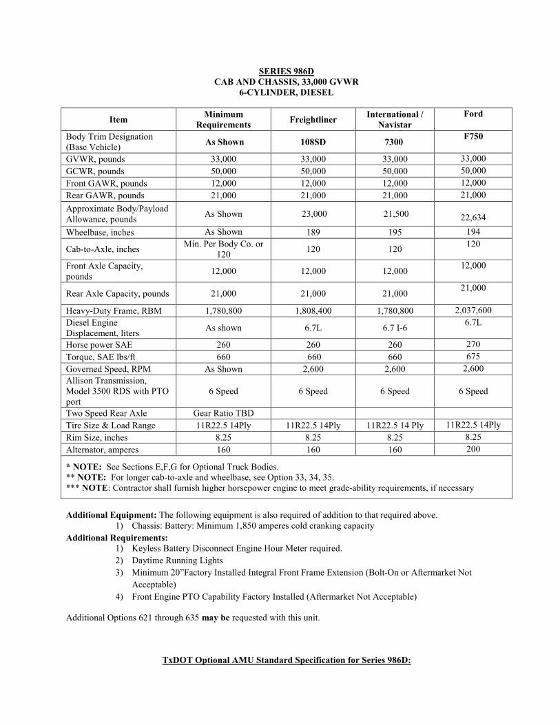
SERIES 986D CAB AND CHASSIS, 33,000 GVWR
6-CYLINDER, DIESEL
Item Minimum Requirements Freightliner International /
Navistar Ford
Body Trim Designation (Base Vehicle) As Shown 108SD 7300 F750
GVWR, pounds 33,000 33,000 33,000 33,000 GCWR, pounds 50,000 50,000 50,000 50,000 Front GAWR, pounds 12,000 12,000 12,000 12,000 Rear GAWR, pounds 21,000 21,000 21,000 21,000 Approximate Body/Payload Allowance, pounds As Shown 23,000 21,500
22,634
Wheelbase, inches As Shown 189 195 194
Cab-to-Axle, inches Min. Per Body Co. or 120 120 120 120
Front Axle Capacity, pounds 12,000 12,000 12,000 12,000
Rear Axle Capacity, pounds 21,000 21,000 21,000 21,000
Heavy-Duty Frame, RBM 1,780,800 1,808,400 1,780,800 2,037,600 Diesel Engine Displacement, liters As shown 6.7L 6.7 I-6 6.7L
Horse power SAE 260 260 260 270 Torque, SAE lbs/ft 660 660 660 675 Governed Speed, RPM As Shown 2,600 2,600 2,600 Allison Transmission, Model 3500 RDS with PTO port
6 Speed 6 Speed 6 Speed
6 Speed
Two Speed Rear Axle Gear Ratio TBD Tire Size & Load Range 11R22.5 14Ply 11R22.5 14Ply 11R22.5 14 Ply 11R22.5 14Ply Rim Size, inches 8.25 8.25 8.25 8.25 Alternator, amperes 160 160 160 200
* NOTE: See Sections E,F,G for Optional Truck Bodies. ** NOTE: For longer cab-to-axle and wheelbase, see Option 33, 34, 35. *** NOTE: Contractor shall furnish higher horsepower engine to meet grade-ability requirements, if necessary
Additional Equipment: The following equipment is also required of addition to that required above.
1) Chassis: Battery: Minimum 1,850 amperes cold cranking capacity Additional Requirements:
1) Keyless Battery Disconnect Engine Hour Meter required. 2) Daytime Running Lights 3) Minimum 20”Factory Installed Integral Front Frame Extension (Bolt-On or Aftermarket Not
Acceptable) 4) Front Engine PTO Capability Factory Installed (Aftermarket Not Acceptable)
Additional Options 621 through 635 may be requested with this unit.
TxDOT Optional AMU Standard Specification for Series 986D:

Specifications and Requirements for Fleet Automobiles and Trucks
128
ASPHALT MAINTENANCE UNIT, TRUCK-MOUNTED,
ONE-MAN OPERATED, 1,500 GALLON
SPECIFICATION FOR OPTIONAL AMU –MUST SEE VARIANCE OPTIONS TO BE QUOTED IF THIS OPTION IS SELECTED
1. SCOPE: This specification describes a one-man operated Asphalt Maintenance Unit (AMU) consisting of a truck chassis and an asphalt application device with a tank. The tank shall hold a minimum rated capacity of 1,500 gallons of asphalt. The rear axle loading shall not exceed 20,000 lbs. when fully loaded to rated capacity. The tank shall have a minimum 10 percent reserve volumetric capacity. The unit shall be designed and constructed to provide asphalt application operations controlled from the truck cab by the driver-operator. The unit will be used in large, multi-mile, chip seal operations. A unit furnished to this specification shall meet or exceed the following requirements.
2. STATEMENT OF INTENT
2.1. A unit furnished to this specification will be used in the application of water and solvent based asphaltic material for road repair and maintenance. The Contractor shall be responsible for designing and furnishing a unit that shall meet all of the performance requirements and design criteria required for the unit to uniformly and consistently apply asphaltic materials at rates and temperatures specified. Loaded weight of the unit shall be based on an asphalt weight of 8.333 lbs. per gallon with all tanks full, less driver. The unit’s rear axle loading shall not exceed rated capacity of the axle when the unit is fully loaded. The 1500 gallon unit shall also be structurally able to carry 1650 gallons of asphalt without exceeding a rear axle load of 21,000 lbs. All units delivered may be weighed for compliance and performance tested as defined in Part III, Para. 2.2. The completed unit when loaded to rated capacity shall be legally and structurally designed to be driven on the highway at 65 mph.
2.2. The asphaltic materials to be applied and the temperature at which they will be applied are specified in Texas Department of Transportation, Standard Specification for Construction, and Maintenance of Highways, Streets, and Bridges 2014 Edition Specifications Book. This information is available at the following web site:
www.txdot.gov/business/specifications.htm
EXAMPLES: BearCat BC-502 Etnyre Black-Topper Centennial Mauldin Precision Spray Rosco Model Maximizer 3 with EZ2S Computer or equal.
NOTICE TO RESPONDENT: Any example shown is listed to show type and class of equipment desired. Respondent is cautioned to read the specification carefully, as there may be special requirements not commonly offered by the equipment manufacturer. DO NOT ASSUME STANDARD EQUIPMENT MEETS ALL OF THE DETAILED SPECIFICATION REQUIREMENTS MERELY BECAUSE IT IS LISTED AS AN EXAMPLE. Respondent is cautioned that any unit delivered to the FOB point that does not meet specifications in every aspect will not be accepted.
3. PERFORMANCE REQUIREMENTS: All asphalt application functions shall be operational from the cab and controlled by the driver-operator. The unit shall meet or exceed the following:
3.1. Operate at ambient temperatures of 40°F and higher.
3.2. Uniformly and consistently apply asphaltic materials at specific pre-selected rates of 0.25, 0.30, 0.35, and 0.40 gallons per square yard with a maximum spraybar width noted below. This shall be accomplished while using Size 3 nozzles (Ref. Part V, Para. 2.3.). The computer or controller shall simultaneously and automatically maintain and hold the pre-selected application rate, as long as the unit maintains a minimum operational speed of 1500 RPM, and while the spraybar spray

Specifications and Requirements for Fleet Automobiles and Trucks
129
pattern width varies from 2 feet to the maximum width.
3.2.1. Spraybar maximum width up to 20 feet.
3.3. Heat, circulate, and apply all types of asphalt listed below in 4.6. Asphalt Pump, including emulsion and heavy oils (EXAMPLE: RC 250). The application rate shall have a range of tolerance of ± 2/100 gallon per square yard. This application rate shall be accomplished without heating the asphalt to more than the maximum allowable application temperature shown in Table 19 (Ref. page 183) TxDOT 2014 Standard Specifications for Construction and Maintenance of Highways, Streets & Bridges, adopted November 2014.
3.4. Uniformity of application of the spraybar shall vary no more than ± 7-1/2 percent per nozzle over the entire length of the spraybar. Asphalt application rate shall be maintained regardless of truck speed, truck gear, or spraybar length.
4. DESIGN REQUIREMENTS: The unit shall meet or exceed the following:
4.1. BASE: The asphalt maintenance unit shall be of heavy-duty construction, designed, and engineered to be an integral part of the truck chassis specified on the solicitation. The unit shall meet DOT 406, specification cargo tank requirements as specified in: Code of Federal Regulations (CFR), Title 49, Part & Sections: 173.247, 178.345 and 178.346 and meet any other applicable federal and state requirements for transport of elevated temperature materials with a flash point at or above 100 degrees.
4.2. TANK: The tank shall be an elliptical cylinder with dimensions designed and engineered for proper load distribution and mounted on the truck chassis to allow for expansion and contraction of tank without placing undue stress on the tank shell or the truck chassis frame. The tank shall meet or exceed the following requirements:
4.2.1. Tank shell, heads, and surge plates shall be constructed of tank-quality steel minimum 10 gauge.
4.2.2. All seams shall be electrically welded on both inside and outside.
4.2.3. Equipped with two full-circumference surge plates which allow necessary circulation of material and do not interfere with operation even when shooting the full width of the spraybar.
4.2.4. Surge plate crawl holes shall be a minimum of 20 inches in diameter with staggered placement.
4.2.5. Have a minimum 20 inch diameter manhole with a quick-opening hinged type cover. Manhole cover shall have a gasket and safety latch. A nominal 20 inch diameter removable manhole strainer shall be provided.
4.2.5.1. A spillage collar around the manhole for units that have an external overflow shall have a minimum 3 inch overflow drain.
4.2.5.2. A spillage collar around the manhole for units that have an internal overflow shall have a minimum 2 inch overflow drain.
4.2.6. Venting: The preferred method of venting of fumes shall be accomplished by venting out the top of the tank. When fumes are vented out the bottom of the tank, Contractor shall furnish a minimum 3 inch diameter x 10 foot long flexible metal hose with airtight coupling to vent fumes away from

Specifications and Requirements for Fleet Automobiles and Trucks
130
the tank. This flexible bottom vent hose shall be rated for minimum 200ºF service. Hose shall be stored on a side hose bracket when not in use.
EXAMPLE: Evertite Type F tank adapter and Evertite Type C hose coupling or equal.
4.2.7. Material Overflow: A minimum 3 inch overflow pipe shall be provided to direct overflow material away from the tank.
4.2.8. Insulated complete tank with a minimum of 2 inches of waterproof rock wool or 1 lb. density glass fiber. Two inch spacers shall be installed to prevent compression of the insulation material. Tank shall be covered with a minimum 0.04 inch weatherproof aluminum jacket. Painted steel tank jacket heads or ends are acceptable.
4.2.9. Provided with an oil-filled thermometer well on the side of the tank, readily visible from ground level. Unit shall include an armored, engraved pencil-type thermometer with a minimum range of 50°F to 450°F.
4.2.10. Include a shut-off valve in the supply line between tank and asphalt pump. The supply line shall enter the tank at as low a point as possible. There shall be an easily accessible screen between the tank and the pump to allow for cleaning of the screen.
4.3. AUTOMATIC RATE CONTROL SYSTEM: The unit shall be equipped with an automatic LCD readout type microprocessor driven cab control computerized system which automatically controls the liquid bituminous spreading rate with 0.01 to 4.0 gallons per square yard. Unit shall be installed in the cab with all computer functions accessible with a single control switch. As a minimum, the system shall perform the following functions:
4.3.1. Have diagnostic troubleshooting system for pinpointing malfunctions. System operation shall be explained in the operations manual.
4.3.2. Provide an automated rate selection with digital display of the pre-selected rate. Pre-selected rate shall be displayed in gallons per square yard.
4.3.3. Have built-in memory which shall hold and maintain the preselected application rate setting(s).
4.3.4. Automatically maintain pre-selected application rate within variables as defined in this document, without requiring the use of a handheld slide rule or calculator.
4.3.5. Set spraybar width.
4.3.6. Activate spraybar with instantaneous on and off.
4.3.7. Display asphalt pump Gallons Per Minute (GPM), forward rate of speed in Feet Per Minute (FPM), total square yards sprayed and total feet traveled.
4.3.8. Retain and display indefinite memory on feet sprayed and distance traveled.
4.3.9. Have master cutoff switch for system power.
4.3.10. Automatically shut off spraybar if wing is raised while shooting and automatically re-activate when lowered.
4.3.11. Display and register temperature of asphalt in the tank. The temperature displayed shall be within 5 percent of the temperature registered on the thermometer specified in Part II, Para. 4.2.9. and the temperature indicated

Specifications and Requirements for Fleet Automobiles and Trucks
131
by the dial thermometer referenced in Section 4.17 in this TxDOT specification.
4.4. VALVES AND PIPING: All valves shall have riveted stamped metal tags or raised permanent type markings adjacent to valve handles to indicate the valve positions (open or closed) for the functions listed. Piping and valving shall be provided to perform the following operations:
4.4.1. Fill the tank from drums or supply tanks using the unit's asphalt pump. Provide one rear mounted 3 inch diameter fill line with quick connect coupling and end cap. This line shall be mounted as low as possible. Unit shall be plumbed to permit filling of the tank without asphalt routing through the unit's pump. Provide a 3 inch diameter bottom drain line with shut off valve (gate) located as close to the tank as possible. The valve handle shall be accessible from outside the chassis frame. The bottom drain line shall extend to the driver’s side of the unit with a quick connect coupling and end cap. Bottom drain line shall permit draining and filling of the tank without asphalt touching the unit's pump.
4.4.2. Circulate material in the tank while heating.
4.4.3. Spray from the tank through the hand spray with the spraybar off.
4.4.4. Spray from tank through spraybar.
4.4.5. Drain pump and lines without draining the tank.
4.4.6. Transfer material from one outside source to another source. Provide one rear mounted 3 inch diameter transfer line with shut-off valve, quick connect coupling, and end cap. This line shall be mounted as low as possible.
4.4.7. Circulate through the spraybar while heating.
4.4.8. Empty tank using asphalt pump. The residual amount of material remaining in the tank shall be no more than 1 percent of total tank capacity.
4.4.9. Switch spraybar from spray to circulate in bar through in-cab controls.
4.4.10. Suck Back: Utilize asphalt pump to suck material back into tank from spraybar, lines, and pump.
4.5. HIGH PRESSURE DIESEL (FUEL OIL) HEATING SYSTEM: The unit shall have a heating unit fueled by diesel.
4.5.1. Two sets of flues shall be mounted to heat material in the tank. The flues shall operate independently of one another to allow heating of varying amounts of material safely.
4.5.2. Heating flues shall have a minimum wall thickness of 0.165 inches and a minimum diameter of 8 inches, or 8 inches tapered to 6 inches. All bends shall be smooth radius bends or double mitered. Square and rectangular flues are not acceptable.
4.5.3. Flues shall be equipped with easily replaceable stainless steel or ceramic liners flue liners.
4.5.4. Vertical exhaust stacks shall be made of stainless steel
4.5.5. Burners: The heating unit shall have two high pressure burners, which are self-contained electrically driven diesel burners with electronic push button ignition and automatic outfire control. Combined capacity of 14 gallons per

Specifications and Requirements for Fleet Automobiles and Trucks
132
hour, producing 945,000 BTU (997 x 10 degrees) per hour, per burner. Unit shall include a manually adjustable thermostat control of 50°F to 450°F. Burners shall have an electrically operated electronic ignition system complete with safety cutoff switch to cut off fuel in case the flame is unintentionally extinguished.
4.5.5.1. Wind shields shall be installed on units with automatic (not electronic) ignition systems to prevent the ignition flame from extinguishing or being directed away from the thermocouple.
4.5.5.2. Heating unit shall be equipped with a system which automatically shuts down the burners if the unit travels more than 5 mph.
4.5.5.3. The fuel system shall include all necessary forged steel piping connections, regulators, and valves and be ready for continuous operation.
4.5.6. The unit shall be equipped with a separate diesel tank to fuel the burners. The tank capacity shall be sufficient for eight hours of operation.
NOTE: Drawing fuel from the truck chassis tank to fuel or fire the burners is prohibited by law.
4.5.6.1. Unit shall include a rain cap venting, directed upward to the atmosphere away from the burners.
4.6. ASPHALT PUMP: Pump shall be rotary-gear, positive-displacement type, designed to handle all grades of liquid asphalt (including: asphalt cement, latex modified asphalt, cutback asphalt, and emulsified asphalt) at 400 GPM. Pump shall include, but not be limited to the following:
4.6.1. Pressure relief valve or bypass arrangement to eliminate danger of excessive pressure in the lines and permit bypassing of material when valves are closed.
4.6.2. Strainer(s) readily accessible for cleaning, installed in the pump's intake line(s) to prevent foreign objects from entering and damaging the pump.
4.6.3. Reversible feature, if necessary to suck back asphalt from spraybar, as required in 4.4.10.
4.7. ASPHALT PUMP TRANSMISSION SYSTEM: Shall power asphalt pump to produce a minimum of 400 GPM when pumping all types and grades of liquid asphalt listed in 4.6.
4.7.1. Hydraulic variable displacement pump shall be mounted to the automatic transmission PTO. The hydraulic pump shall be hydrostatic type with controls in the truck's cab convenient to operator.
4.7.2. Hydraulic motor complete with hydraulic reservoir, temperature gauge and replaceable element type filter incorporated in the hydraulic system. Red indicator light for high hydraulic oil temperature shall be installed in cab.
4.7.3. Hydraulic cooling system shall be of the manufacturer’s method and design and shall keep the hydraulic fluid from overheating.
4.8. SPRAYBAR: Spraybar shall be full circulating type with the following functions controlled from the cab. The spray-bar, cab controls, and rear controls shall be designed to accommodate up to 20’ of bar and shall comply with the following requirements:
4.8.1. Basic (center section) length shall be 8 feet with one folding

Specifications and Requirements for Fleet Automobiles and Trucks
133
2-foot extension on each end to provide a spraybar length of 12 feet or a telescoping spray bar that can extend from 8 feet to a minimum 16 feet. If used, extensions shall fold vertically (90°) for transport either hydraulically or pneumatically without the use of tools. Means shall be provided to secure the extensions in the transport position. Overall spraybar width shall not exceed 8 feet when in the transport position with extensions folded.
4.8.2. Spraybar shall accept additional sections or extensions as identified on the PO
4.8.2.1. The spraybar shall be expandable to 20 feet in width.
4.8.3. Spraybar shall horizontally shift a minimum 10 inches from either side of the centerline of the unit.
4.8.4. Spraybar vertical travel (from the tip of the spraybar nozzle) shall lower to within 8-1/2 inches off the ground and lift a minimum of 15 inches above the ground.
4.8.5. Spraybar shall move horizontal and vertical shifting throughout the ranges referenced in. 4.8.3. and 4.8.4.
4.8.6. Spraybar shall have a safety relief feature to prevent damage to the spraybar should the outer sections or extensions strike an obstruction in the forward or reverse movement of the unit. Anything outside the legal width of the truck shall be equipped with safety reliefs.
4.8.7. Spraybar shall be designed so that it can be isolated from the pumping system of the maintenance unit for extensive hand spray use or to circulate material in the tank without material entering the spraybar.
4.8.8. Spraybar shall be fitted with individual non-clogging nozzles to produce a fan-shaped spray. Nozzle sizes shall be as identified in the solicitation. Nozzles shall be placed at 4 inch intervals for overlapping coverage during normal application work. Nozzles shall be labeled with either size or part number (PN). If PNs are used, a translation of PN to application rate per square yard shall be provided with the unit.
4.8.9. Spraybar shall have a separate valve for each nozzle.
4.8.10. Spraybar minimum inside cross section area shall be 6.56 square inches.
4.9. HAND SPRAY WAND: Hand spray equipment shall consist of a 50 foot section of 3/4 inch ID hose designed for use in asphalt operations. The hose shall be complete with swivel-type coupling at the hand wand and all necessary fittings, insulated or cold handle(s), fan type spray nozzle(s), shut-off valve, and a manually operated hose storage reel. Hose shall be flexible enough to be easily stored on the hose storage reel mounted on the unit.
4.10. CONTROLS: All controls for spray operation and pump operation shall be located in the truck's cab convenient to the driver-operator and meet the requirements in TxDOT specification document section 4.3. All control valves shall be leakless type. The controls shall be electric over air or electric over hydraulic. Cab and rear controls shall accommodate up to a 20’ bar and shall meet or exceed the following requirements:
4.10.1. Incremental, instantaneous on/off control throughout the spraybar. On/off controls shall be based on maximum 1 foot sections throughout the entire length of the spraybar including any additional sections or extensions. Telescoping spraybars may have on/off controls for a 2 foot section on

Specifications and Requirements for Fleet Automobiles and Trucks
134
either side of the center of the spray bar. Controls shall enable the operator or driver to pre-select the application rate(s) noted in Part II, Para. 3.2. from the driver’s seat.
4.10.1.1. On controls: When a section or sections of the spraybar are turned on, all nozzles sectioned shall immediately and simultaneously open to produce uniform fan-shaped spray patterns without drips or distortions. This no-drip actuation shall occur when the unit is starting a shot from a stationary position. Actual asphalt coverage shall be in accordance with this TxDOT specification Section 3.1. through 3.4.
4.10.1.2. Off controls: When section(s) of the spraybar are turned off, all nozzles in the section(s) shall immediately and simultaneously close to terminate the uniform fan-shaped spray patterns without drips or distortions. This no-drip actuation shall occur whenever the unit is terminating a shot.
4.10.1.3. The instantaneous on/off control throughout the entire spraybar including any extensions (wings), shall provide a straight clean line that shall eliminate the need for the use of paper laid across the roadway to achieve sharp asphalt-to-road surface line definition.
4.10.2. Spraybar horizontal shift, vertical shift, and wing-lift controls.
4.10.3. A unit utilizing air pressure for control functions shall have a reservoir separate from the truck's air brake reservoir complete with a check or safety valve and automatic moisture ejector.
4.10.4. The following functions shall be controlled from the cab:
4.10.4.1. On/off switch.
4.10.4.2. Circulation in spraybar.
4.10.4.3. Spraybar application in 1 foot increments.
4.10.5. The following controls shall be located in the cab and rear control panel except as noted:
4.10.5.1. Raising spraybar wings, which shall automatically shut off when raised.
4.10.5.2. Lowering spraybar wings.
4.10.5.3. Center and raise the wings of the spraybar for travel.
4.10.5.4. Flush or transfer. May be located at rear only.
4.10.5.5. Distributor pump load. May be located at rear only.
4.10.5.6. Handspray and unload. May be located at rear only.
4.10.5.7. Pump to spraybar clean or suck back. May be located at rear only.
4.11. EMERGENCY SHUTDOWN: An emergency shutdown control shall be located in the rear panel in addition to the controls in the cab. Prominent labeling meeting the requirements referenced in this TxDOT specification Section 4.4. shall be furnished.

Specifications and Requirements for Fleet Automobiles and Trucks
135
4.12. LADDER, CATWALK, AND REFINERS PLATFORM: A ladder shall be provided at the curbside or rear of the tank meeting the requirements of latest revision to the Truck Trailer Manufacturer’s Association (TTMA), Recommended Practice – RP No. 59, Tank Trailer Ladders and Walkways (http://www.ttmanet.org/). Ladder shall allow easy access from ground level to the top of the tank. Ladder shall be positioned so an operator approximately 5 feet, 6 inches in height shall be able to easily grab the ladder railings without bending, while standing at ground level and facing the step of the unit. Ladders mounted rear or curbside shall enable operator access to the manhole without touching, standing on, or coming into contact with any components of the unit. Bottom rung of ladder shall be high enough so that operator’s foot shall not come into contact with the pump or any other component. If rear mounted ladder is provided, it shall extend a minimum of 2 feet, 6 inches above the catwalk enabling the operator to safely step onto the catwalk from the top of the ladder. Lower rails shall have L-shaped extensions to the rear deck (refiner’s platform) area for ease of access to the ladder by operator. A full length by minimum 24 inch wide, grip-strut catwalk shall be provided on the top of the tank with a refiner’s platform at the manhole.
4.13. RADAR OR SPEED SENSING UNIT: A radar or speed sensing unit that digitally indicates FPM shall be calibrated with minimum 1 FPM gradations as well as total feet traveled. The unit shall be integrated with the control system referenced in Part II, Para. 4.3. with read-out displayed in the truck's cab. The unit shall automatically begin indicating speed when the spraybar is turned on, and shall also have override to allow operation independently of the spraybar. GPS systems are not acceptable
EXAMPLE: DICKEY-john Dj RVS II Radar Velocity Sensor or equal.
4.14. LOADING HOSE: A 15 foot section of 3 inch diameter flexible metal hose shall be furnished with a coupling for attaching loading hose to intake line. This hose shall be rated at 450°F. A provision shall be made for storing and transporting the loading hose assembly when not in use. Loading hose shall be stored in a manner and location which does not obstruct operation of the unit. The hose shall be equipped with two loading hose fittings, one for fill and one for discharge.
4.15. MEASURING STICK: A steel or aluminum measuring stick shall be furnished, calibrated in standard U.S. gallons as to tank volume. This stick shall be designed to read tank contents without dipping stick into material, and will be used to confirm application rates. Calibration shall be in 10 gallon increments. The measuring stick shall be stored inside the tank's overflow pipe or in clips on the side of the tank when not in use. A second measuring stick (calibrated to the tank) meeting the above requirements shall also be furnished.
4.16. TANK GAUGES: Tank shall be equipped with two calibrated, durable gauges reading in 25 gallon graduations, accurately indicating the liquid content of the tank at all times, with one visible from the driver’s seat and the other visible from the rear control panel.
4.17. DIAL THERMOMETER: A minimum 4 inch dial type thermometer with liquid filled case shall be furnished. Thermometer shall register from 50°F to at least 450°F in 10°F increments to indicate temperature of liquid contents of tank. Thermometer shall be protected and readable by an operator on the ground.
4.18. SPRAYBAR AND PUMP FLUSHING SYSTEM: A self-contained, self-flushing system, connected to a separate 20 gallon minimum diesel tank for cleaning the asphalt out of all plumbing lines, spraybar, and asphalt pump. System shall have all valves, piping, and controls necessary for flushing. System shall suck back used diesel from the spraybar and asphalt pump into the asphalt tank or a separate tank. If separate tank is used this tank shall be minimum 25 gallons and shall have a bottom drain for clean out.

Specifications and Requirements for Fleet Automobiles and Trucks
136
4.19. TRUCK CHASSIS ADDITIONAL REQUIREMENTS:
4.19.1. Curbside Mirror: Right (curb) side of chassis shall be equipped with a minimum 6 inch wide by 15 inch tall, four way electrically controlled mirror that permits easy viewing of spraybar position from the driver’s seat.
4.19.2. Instrumentation: PTO Hourmeter, electric quartz type, shock proof, totally sealed case, with readout up to 9,999.9 hrs. Three screw or flush mount to accommodate equipment system voltage range between 10-80V.
EXAMPLE: Hobbs Three Screw Model 85097-02 Hobbs Flush Mounted Model 85093-03 or equal.
4.19.3. Dual Air Filter: Chassis manufacturer’s heavy dust two-stage filtration system, with a graduated, continuous air restriction indicator device. The air restriction indicator device shall be visible from the ground.
EXAMPLE: Donaldson S Series or equal.
4.19.4. Vertical Exhaust Stack: Chassis engines shall have vertical exhaust stack.
5. APPLICATION CHARTS: Application charts or a sliding type computer for calculating the amount of material required, travel speed and length of spraybar shall be provided.
6. INSTRUCTION ON SAFETY, OPERATION, AND PREVENTIVE MAINTENANCE: The Contractor shall provide the services of a competent factory trained technician thoroughly trained in the use and operation of the unit to TxDOT a minimum 16 hours instruction on safety, operation, and preventive maintenance of the unit. The service shall be provided after the unit has been delivered and is ready for operation but prior to payment.
7. BACKUP ALARM SYSTEM: Shall be distinguishable from the surrounding noise level. The backup alarm shall meet the requirements of current SAE J994.
8. REAR BACK-UP CAMERA SYSTEM: Rear mounted back up color camera with in cab 7” inch monitor. Mounting location of camera and monitor to be prior approved by TxDOT before mounting.
EXAMPLE: Zone Defense, ZD.323.1.15CH Or equal
9. LIGHTING PACKAGE:
9.1. L.E.D. type clearance lights and reflectors meeting Texas Motor Vehicle Laws and Texas Department of Public Safety requirements. Stick-on type reflectors are not acceptable.
9.2. Amber strobe mounted on top at the rear of tank.
10. SAFETY PLAQUES OR DECALS
10.1. Product safety plaques or decals shall be furnished and affixed at the operator's station and at any hazardous area. The safety plaques or decals shall describe the nature of the hazard, level of hazard seriousness, how to avoid the hazard, and the consequence of human interaction with the hazard. Permanent plaques are preferred to decals. Type, size, and location of product safety plaques or decals shall be in accordance with current ANSI Z535.4 standard.
10.2. A permanent lubrication plaque shall be furnished and visible from the outside of the unit. The plaque shall note all lubrication points and recommended periodic oil changes and lubrication intervals.

Specifications and Requirements for Fleet Automobiles and Trucks
137
10.3. An aluminum diamond framed hazardous material flip type placard with removable placard for elevated temperature asphaltic materials shall be provided. Placards shall be mounted to the sides, front, and rear of truck.
11. SAFETY INSPECTION: Unit furnished shall be in compliance with Federal and Texas Motor Vehicle Laws upon delivery, and be ready for inspection and certification by a licensed inspection station.
12. PAINTING: With the exception of the aluminum tank covering and trim, and those accessories or fixtures constructed of rust resistant or plated material not normally painted, the maintenance unit shall be painted with a lead free high quality, heat and rust resistant black enamel. The cab and chassis shall be painted a manufacturer’s standard lead-free white color, except for those accessories or fixtures constructed of rust-resistant or plated material not normally painted.
13. MANUAL(S): One original illustrated parts book, operator's manual, and service manual shall be delivered with each unit. These shall include, at minimum, all appropriate manuals for the engine, transmission, brakes, hydraulic system, controls, and electrical system. It is requested, but not required, that the manuals be printed on recycled paper. Copies of parts book, operator’s manual and service manual are not acceptable. In addition to the original paper manual, Contractor may provide an electronic media version of the current original manual.
13.1. Additionally, one complete set of wiring, plumbing, and hydraulic schematics shall be delivered with each unit. All schematics shall be clear, legible, and indicate the location of each component. Hydraulic schematics shall include the diameter and length of each hose and the manufacturer and part number of each fitting. Copies of schematics are not acceptable.
13.2. The manuals and schematics supplied shall provide complete and comprehensive information on all equipment, equipment components, and accessories, as supplied to comply with this specification. If changes, modifications, additions, or alterations of any kind are made on the equipment, the Contractor shall provide blueprints, line drawings, and descriptive text sufficient to allow one of average skill in general mechanics to diagnose, repair, and maintain the equipment and all components.
13.3. The operator's manual shall include detailed instructions on the proper method of operation of the unit and the procedures for loading, storing, and applying all types’ asphaltic materials as referenced in this TxDOT specification section 4.6 at specific: rates, temperatures, roadway speeds, and spraybar lengths. All necessary warnings and safety precautions shall be included.
13.4. The following additional information shall be provided by the Contractor at time of delivery if it is not included in the manuals required above.
13.4.1. Manufacturer’s recommended service and preventive maintenance intervals.
13.4.2. Recommended fluids, lubricating and their SAE/API equivalents.
14. REPLACEMENT FILTERS: A complete set of replacement filters shall be provided for each unit furnished to this specification (not required for cab and chassis). This set of filters shall include air, fuel, oil, and hydraulic filters used on the equipment. Each filter shall be labeled with the equipment manufacturer's part number as shown in the manufacturer's parts book furnished at the time of delivery. The Filter and Belt Identification Form should be completed in duplicate for informational purposes only. The form can be found at www.dot.state.tx.us/gsd/purchasing/purchasing.htm. The part numbers provided on the form shall correspond with the part numbers found in the parts manual for the equipment.
15. MANUFACTURER'S STATEMENT OF ORIGIN (MSO): Contractor shall furnish MSO to the receiving district with each unit at time of delivery. CUSTOMER WILL NOT ACCEPT
Specifications and Requirements for Fleet Automobiles and Trucks
138
THE UNIT AND PROCESS PAYMENT WITHOUT THE MSO.
16. TITLE APPLICATION FORM: Contractor shall furnish a completed State of Texas Form 130-U, Application for Texas Title and/or Registration, to the receiving district with each unit at time of delivery. The Form 130-U must be the most current version available. TxDOT WILL NOT ACCEPT THE UNIT AND PROCESS PAYMENT WITHOUT THE COMPLETED FORM 130-U.
If TxDOT selects AMU option 986D-AMU, additional options may apply, see below for variance options.
OPTIONAL EQUIPMENT IF AMU IS SELECTED
Prices shall be provided for the optional equipment on the Mandatory Price Sheet.
1. AMU OPTION 1: SPRAYBAR EXTENSIONS – The quantity of spraybar extensions and total spraybar width shall be specified on the PO. Spraybar extensions shall be provided, each being 1 foot in length, designed for quick change or quick addition and interchangeable from side to side. Valve type and installation shall be as specified in Part II, Para. 4.4., of this specification. On/off controls for each 1 foot extension shall be provided in the truck cab as specified in Part II, Para. 4.10.1. of this specification. Hydraulic system intake air shall be filtered.
2. AMU OPTION 2 (MULTIPLE OPTIONS): SPRAYBAR NOZZLES – The spraybar nozzles shall be brass and sized on the PO. The nozzles shall be selected from the sizes listed below:
2.1. AMU OPTION 2.1: SIZE 1, Fog and Tack (1/8 inch Coin Slot) Nozzle, (Application rate = .05 - .20 GAL/yd.2).
EXAMPLES: Etnyre 3351013, Rosco nozzle #0, or equal.
2.2. AMU OPTION 2.2: SIZE 2, Multi-Material (V-Slot) Nozzle, (Application rate = .15 - .40 GAL/yd.2).
EXAMPLES: Etnyre 3352368, Rosco nozzle #1.5, or equal.
2.3. AMU OPTION 2.3: SIZE 3, Multi-Material (V-Slot) Nozzle with end nozzles, (Application rate = .25 - .55 GAL/yd.2).
EXAMPLES: Etnyre 3352205 & 3352210, Rosco nozzle #2, or equal.
2.4. AMU OPTION 2.4: SIZE 4, Multi-Material (V-Slot) Nozzle, (Application rate = .35 - .95 GAL/yd.2).
EXAMPLES: Etnyre 3352204, Rosco nozzle #3, or equal.
3. AMU OPTION. 3: MECHANICAL POINTER GUIDE WITH HYDRAULIC LIFT – A front-mounted adjustable pointer guide shall be provided. The pointer shall be adjustable in length from 6 to 10 feet. Pointer shall be movable from left to right side operating position. The guide shall be capable of angular displacement when assembled for either left or right side operation. In the transport position, it shall fold within the vehicle's width and shall be clamped in position. In the transport position, it shall in no way interfere with the driver's vision. It shall be easily assembled by one person using simple hand tools.
4. AMU OPTION 4: THREE INCH REAR MOUNTED FILL LINE – Provide an additional 3 inch fill line with in-line gate valve, quick connect coupling, and end cap. This fill line may route through the asphalt pump and shall end as low as possible. On/off valve shall be furnished and labeled meeting the requirements of TxDOT SPECS, PARAGRAPH 4.4 ABOVE.
5. AMU OPTION 5: POWER WASH DOWN – The unit shall be equipped with power wash down system to include an electric fuel or oil pump or pneumatic with electric on/off switch located at the rear. Shall be equipped with hand-operated wand to provide sufficient pressure for cleaning the spraybar and rear of unit.
6. AMU OPTION 6: SPIRIT LEVEL(S) – Unit shall be equipped with two spirit levels mounted at the rear of the unit on the driver's side. Spirit levels shall be mounted so that the unit may be readily leveled both longitudinally and transversely by the operator for measuring of the tank contents using the measuring stick provided in TxDOT SPECS, PARAGRAPH 4.15 ABOVE.

Specifications and Requirements for Fleet Automobiles and Trucks
139
7. AMU OPTION 7 (ALL ONE OPTION): LPG HEATING SYSTEM – In lieu of the High Pressure Diesel heating system described in TxDOT SPECIFICATIONS ABOVE PARAGRAPH. 4.5., the unit shall have a LPG fueled heating system. Delete referenced TxDOT specifications in paragraph 4.5 and replace with the following:
7.1. LPG-FUELED HEATING UNIT: The unit shall have a heating unit fueled by LPG. All LPG equipment, including valves, fittings, vessels, etc. and installation, shall be approved for use in the state of Texas as required by the Railroad Commission (RRC) of Texas. A copy of the LPG equipment installer’s license from RRC of Texas shall be submitted with the unit at time of delivery.
7.1.1. Two sets of flues shall be mounted to heat material in the tank. One flue shall be located high and one low. The flues shall operate independently of one another to allow heating of varying amounts of material safely.
7.1.2. Heating flues shall have a minimum wall thickness of 0.165 inches and a minimum diameter of 8 inches, or 8 inches tapered to 6 inches. All bends shall be smooth radius bends or double mitered. Square and rectangular flues are not acceptable.
7.1.3. Flues shall be equipped with easily replaceable stainless steel flue liners.
7.1.4. Vertical exhaust stacks shall be made of Stainless Steel.
7.1.5. Burners: The heating unit shall have two each standard LPG burners, each with a minimum of 1,000,000 BTUs per hour capacity with manually adjustable thermostat control of 50°F up to 450°F. Each burner shall have an electrically operated, automatic or electronic ignition system complete with safety cutoff switch to stop the flow of fuel if the flame is unintentionally extinguished.
7.1.5.1. Wind shields shall be installed on units with automatic (not electronic) ignition systems to prevent the ignition flame from extinguishing or being directed away from the thermocouple.
7.1.5.2. Heating unit shall be equipped with a system which automatically shuts down the burners if the unit travels more than 5 mph.
7.1.5.3. LPG system: The fuel system shall include, but not be limited to; all forged steel piping, connectors, regulators, and valves, and is ready for continuous operation.
7.1.6. LPG Motor Fuel Container: The unit shall be equipped with an ASME-approved motor fuel container, frame mounted with fill access to the right (curb) side of the unit. Capacity shall be sufficient for eight hours of operation. Container shall include:
7.1.6.1. All valves, fittings, gauges, etc. as required by the RRC of Texas.
7.1.6.2. A rain cap venting, directed upward to the atmosphere away from the burners.
7.1.6.3. ASME approval which is legible and readily visible from curbside of unit.
NOTE: The identification plate on the container shall be unpainted stainless steel attached by a continuous 360° weld.
7.1.7. LPG INSTALLERS LICENSE: Contractor shall furnish a copy of the LPG installer’s license issued by the RRC of Texas and documentation indicating the date the system was manufactured and installed at the time of delivery.
8. AMU OPTION 8 (ALL ONE OPTION): SPRAYBAR EXTENSION STORAGE BOXES – Unit shall be supplied with a liquid-tight spraybar extension storage box located in an easily accessible location on the side or under the rear deck of the unit. Box shall meet the following minimum requirements:
8.1. Size: 26 inches long, 14 inches wide and 9 inches in height.
8.2. Constructed of 14-gauge steel on the bottom and all sides.
8.3. Cover shall be hinged, lockable, and constructed of 16-gauge anti-skid plate steel.
8.4. Cover and box rim shall be splash proof and baffled to prevent sloshing of liquid. Box shall have

Specifications and Requirements for Fleet Automobiles and Trucks
140
bottom drain with removable, threaded steel cap.
8.5. Shall be painted black enamel meeting the requirements of this TxDOT Specification Paragraph 12.
9. AMU OPTION 9: TELESCOPING SPRAYBAR – In lieu of the spraybar described in TxDOT SPECIFICATIONS Paragraph 4.8.1., units shall have a minimum 20 foot width telescoping and retracting spraybar. Center section shall be two center bars, 8 feet in length and shall adjust outward in not less than 4 inch increments. Telescoping and retracting controls shall be located in the cab.
10. AMU OPTION 10: TRAINING – The Contractor shall provide a minimum eight hour training class covering all safety, operation, and maintenance procedures, including pre-operational inspection, necessary to adequately prepare an operator prior to using the asphalt distributor in routine work. Class shall be taught by a factory authorized instructor. Training to take place within 21 days of delivery at location determined by TxDOT.
11. AMU OPTION 11: TRAINING VIDEO – A produced video program of full broadcast quality shall be provided in DVD format for instructional training. The video shall be detailed as possible covering all safety, operation, and maintenance procedures, including pre-operational inspection, necessary to adequately prepare an operator prior to using the asphalt distributor in routine work. The video shall include, but not be limited to the following:
11.1. Asphalt loading and unloading procedures.
11.2. Detailed procedures on heating operations for diesel and propane burner systems.
11.3. Suck back procedures.
11.4. Safety issues: Operational warnings, precautions, recommendations, and details related to the use of specific asphaltic materials.
11.5. Exterior care and cleaning of asphalt units with emphasis on proper spraybar and nozzle cleaning.
11.6. Periodic maintenance, to include lubrication and adjustments of all components, winterizing, and long term storage procedures and precautions.
12. AMU OPTION 12: EXTRA SET OF MANUALS – In addition to the manuals required in TxDOT SPECIFICATIONS Paragraph 13, one extra set of operator’s service and parts manuals shall be provided at time of delivery.
13. AMU OPTION 13: COMPLETE SET OF OVERHAUL MANUALS – In addition to the manuals required IN TxDOT SPECIFICATIONS Paragraph 13, one complete set of specialized major overhaul or technical manuals for the engine, transmission, hydraulic system, electrical system, etc., shall be provided at time of delivery.
14. AMU OPTION 14: ELECTRIC BELLY HEAT – 220V single phase or 440V 3 phase, with thermostat to maintain heat.
THIS ENDS TxDOT SPECIFICATIONS FOR THIS SERIES

Specifications and Requirements for Fleet Automobiles and Trucks
141
SERIES 990D CAB AND CHASSIS, REGULAR CAB
35,000 GVWR 6-CYLINDER, DIESEL
Additional Equipment: The following equipment is required in addition to that required above:
a. Body: 1. Hood, Forward Tilting 2. Engine: Shall be In-Line 6-Cylinder 3. Keyless Battery Disconnect & Engine Hour Meter required. 4. Daytime Running Lights
b. Chassis:
1. Air Brake Lines: Complete with trailer air couplings (with suitable protection to restrict dirt from entering coupling) and 7-wire electrical hook-ups. Lines shall be routed through the chassis to the end of frame and shall be securely fastened to the frame at intervals sufficient to prevent sagging and to provide clearance of any mechanical parts. Rubber grommets shall be used wherever air or electrical lines pass through metal.
2. Batteries: Minimum 1,200 amperes cold cranking capacity. 3. Brakes, Straight Air: Manufacturer's standard with desiccant type air dryer, designed for towing air brake
ITEM Minimum Req. Freightliner Navistar Kenworth
Body Trim Designation (Base Vehicle) As Shown M2 4000
GVWR, pounds 33,000 33,000 35,000 35,000 GCWR, pounds 50,000 50,000 50,000 50,000 Front GAWR, pounds 12,000 12,000 12,000 12,000 Rear GAWR, pounds 23,000 23,000 23,000 23,000
Approximate Body/Payload Allowance, pounds As Shown 23,000 20,000 23,500
Wheelbase, inches 128/152 158 128/152 152 Cab-to-Axle, inches 84 84 85 84
Front Axle Capacity, pounds 12,000 12000 12,000 12,000
Rear Axle Capacity, pounds 23,000 23,000 23,000 23,000
Heavy-Duty Frame, RBM ** 1,275,200 1,358,400 1,275,200 1,776,000
Diesel Engine Displacement, liters As Shown 8.9L 9.0L I-6 9.0L I-6 8.3L I-6
Horsepower, SAE 260 270 275 260 Torque, SAE, lbs-ft 800 800 860 800 Governed Speed, RPM As Shown 2,200 2200 2,600
Transmission, Manual (Standard) 6 or 7 Speed OD 6 or 7 6 or 7 7 or 9 speed
Tire Size & Load Range 11R-22.5G 11R-22.5G 11R-22.5G 11R22.5G Rim Size, inches 8.25 8.25 8.25 8.25x22.5 Alternator, amperes 160 160 160 160 * NOTE: See Sections F,G,H for Optional Truck Bodies. ** NOTE: For longer cab-to-axle and wheelbase, see Option 33.

Specifications and Requirements for Fleet Automobiles and Trucks
142
equipped trailers. Complete with dummy glad hand seals. 4. Clutch: Minimum 13-inch diameter with two plates, or minimum 14” single plate.5. Compressor, Air: Minimum 13.2 CFM with reservoir and low-air pressure warning indicator in cab.6. Coolant System: Manufacturer's maximum cooling.7. Moisture Ejector, Automatic: Manufacturer's standard (installed on wet tank).8. Parking Brake, Spring-Set Type: Manufacturer's standard mounted forward of rear axle.9. Slack Adjusters: Automatic adjusting type, front and rear.10. Tachometer: Manufacturer's standard.11. Trailer Package: Including hand-control valve, tractor-protection valve, and dummy for glad hands.12. Visual Brake Stroke Adjustment Indicators13. Wheel bearings shall be fluid lubricated with synthetic lubricants.14. Oil seals shall be wet-type standard two-piece with sight glass
* NO EQUIPMENT SHALL BE BOLTED INSIDE THE FRAME FROM A POINT IMMEDIATELY BEHIND THE CAB AND EXTENDING 9 INCHES TOWARD THE REAR OF THE UNIT. IN ADDITION, A CLEAN FRAME RAIL SHALL BE PROVIDED ON THE PASSENGER SIDE FROM THE BACK OF THE CAB TO THE FRONT OF THE REAR SPRING HANGER.
TxDOT Optional Aviation Re-Fueler Truck Standard Specification for Series 990D
1. 3000 GALLON CAPACITY2. 100 GPM JET REFUELEREXAMPLE: GARSITE MODEL #3M-100-SC OR EqualCHASSIS INFORMATION:
a) SERIES 990D, TxDOT SPECIFIED CHASSISb) ALLISON AUTOMATIC TRANSMISSION W/PTO PROVISION
3. TANK INFORMATION:a) 3000 U.S. GALLON CAPACITY (3% OUTAGE),b) UNPAINTED NATURAL BRIGHT FINISH ALUMINUM,c) FULLY BAFFLED,d) SINGLE COMPARTMENT,OVERTURN PROTECTIONe) 20" MANHOLE, AND 10" FILL OPENING & VENTf) ONE REAR MOUNTED TANK ACCESS LADDER MUST BE INSTALLED TO MEET OSHA 29
CFR 1910.674. PUMP SYSTEM:
a) 100 GPM CENTRIFUGALb) PTO DRIVENc) HOT SHIFT PUMPING SYSTEM WITH 2 OVERWING HOSES, REELS AND FLOW METERS
FOR DUAL OVERWING FUELING CAPABILITIES.5. SYSTEM CONFIGURATION:
a) DISPENSING EQUIPMENT WILL BE LOCATED IN DRIVER'S SIDE OPEN CABINET.6. HOSES:
a) TWO (2) 1 1/4" X 50 FOOT AVIATION REFUELING HOSES WITH N/R MALE COUPLINGSCERTIFIED TO API 1529.
7. OVERWING NOZZLES:a) TWO (2) JET OVERWING NOZZLES WITH SWIVELS & 100 MESH STRAINER
8. HOSE REELS:a) TWO REELS;
I. ONE SINGLE WRAP SIZED FOR 1 1/4"X 50'HOSE LOCATED BEHIND CHASSISCAB.
II. ONE DRUM STYLE SIZE FOR 1 1/4"X 50'HOSE LOCATED IN THE OPEN SIDECABINET.

Specifications and Requirements for Fleet Automobiles and Trucks
143
III. REELS WILL INCLUDE NON-FERROUS INTERNALS. IV. EXPLOSION PROOF ELECTRIC REWIND MOTORS & SWITCHES. V. AUXILIARY MANUAL REWIND.
VI. SHUTOFF VALVE WILL BE INSTALLED IMMEDIATELY UPSTREAM OF EACH REEL.
9. METERS: a) TWO (2) DIGITAL METERS, WITH LARGE NUMERAL RESET COUNTER AND TOTALIZER. b) REGISTERS IN WHOLE U.S. GALLONS.
10. BOTTOM LOADING: a) INCLUDE A JET LEVEL SENS OR CONTROL SYSTEM FOR AUTOMATIC, HIGH-LEVEL
SHUTOFF WITH PRE-CHECK AS SECONDARY EMERGENCY SHUT-OFF SOURCE. b) THE BOTTOM-LOADING ADAPTER, CAPABLE OF ACCEPTING AN INTERNATIONAL
STANDARD 3-LUG UNDERWING NOZZLE, WILL BE INSTALLED ON DRIVER'S SIDE. c) A GAUGE AND SHUTOFF VALVE WILL BE INSTALLED IMMEDIATELY DOWNSTREAM
OF BOTTOM LOAD. d) A MECHANISM SHALL BE INSTALLED TO AUTOMATICALLY OPEN THE OPERATING
VENT & BELLY VALVE WHEN BOTTOM LOADING OCCURS. 11. SCULLY OVERFILL PROTECTION SYSTEM:
a) SCULLY 09409 SP-TO THERMO OPTIC PROBE b) SCULLY 09065 SP-MHC PROBE HOLDER c) SCULLY SJ-6S 8-PIN THERMISTER SOCKET WITH GREEN COVER, & GROUND LUG
SHALL BE INSTALLED AS PRIMARY HIGH-LEVEL SHUTOFF. 12. FILTRATION SYSTEM:
a) FILTER/SEPARATOR SYSTEM WITH CATEGORY M FILTER ELEMENTS FOR USE WITH FUEL PRE-BLENDED WITH FSII (PRIST).
13. PIPING: a) ALL PIPING WILL BE 2" ALUMINUM PRESSURE RATED FOR THE FLOW RATE.
14. CENTRALIZED CONTROL SYSTEM: b) ALL PRIMARY REFUELER FUNCTIONS (INCLUDING PTO & PRODUCT PUMP, VENTS,
BRAKE INTERLOCK, & PRESSURE CONTROLS) ARE TO BE ROUTED TO A CENTRAL HUB TO ALLOW FOR EASE OF ACCESSIBILITY, QUICK DIAGNOSTICS, AND SIMPLE INSPECTION.
15. AUTOMATED PTO ENGAGEMENT SYSTEM: a) AN AUTOMATIC PUMP ENGAGEMENT SYSTEM SHALL BE PROVIDED. b) PUMP SHALL BE AUTOMATICALLY ENGAGED, AND THE OPERATING VENT &
OFFLOADING VALVE WILL OPEN WHEN THE OVERWING NOZZLE(S) IS REMOVED FROM ITS HOLDER(S).
c) SYSTEM WILL ACT AS A SAFETY MECHANISM. 16. SAFETY & MAINTENANCE ITEMS: (THE FOLLOWING ITEMS WILL BE INCLUDED)
a) ONE STATIC REEL WITH 50' CABLE AND BONDING CLAMP MOUNTED ON DRIVER'S SIDE.
b) BRAKE INTERLOCK SYSTEM TO APPLY THE BRAKES WHEN EITHER THE AUTOMATED PTO ENGAGEMENT SYSTEM OR THE BOTTOM-LOAD SYSTEM IS ACTIVATED.
c) AN INTERLOCK OVERRIDE SYSTEM WITH INDICATOR LIGHT SHALL BE INSTALLED TO ALLOW MOVEMENT OF THE REFUELER FOR MAINTENANCE PURPOSES SHOULD AN INTERLOCK FAIL.
d) EMERGENCY SHUTDOWN SYSTEM WITH (2) SHUT-OFFS. ONE ON EACH SIDE OF THE VEHICLE.
e) EMERGENCY FUEL SHUT-OFF" WILL BE DISPLAYED BY EACH SHUT-OFF IN LETTERS AT LEAST 2" HIGH CONTRASTING WITH THE BACKGROUND.
f) THE METHOD OF SHUT-OFF OPERATION WILL ALSO BE INDICATED BY ARROW OR PUSH OR PULL.
g) TWO (2) PROPERLY MOUNTED 20-B:C FIRE EXTINGUISHERS. h) AUDIBLE, BACK-UP ALARM. i) FLASHING BEACON LOCATED ON TOP OF THE CHASSIS CAB. (Beacon Will Operate
Whenever Ignition Switch Is Turned On.)

Specifications and Requirements for Fleet Automobiles and Trucks
144
j) TWO (2) HIGH MOUNTED LED SPOT LIGHTS LOCATED NEAR THE FRONT OF THE TANK AND AT THE REAR ON THE REEL SIDE OF THE TRUCK THAT CAN BE ADJUSTED FOR NIGHT FUELING.
k) SHUT-OFF VALVES BEFORE AND AFTER THE FILTER VESSEL. l) MAINTENANCE VALVE DOWNSTREAM FROM THE BELLY VALVE. m) DIFFERENTIAL PRESSURE GAUGE n) PUMP PRESSURE GAUGE o) SYSTEM PRESSURE GAUGE
I. All THREE ABOVE GAUGES WILL BE INSTALLED IN THE DISPENSING CABINET. 17. ADDITIONAL ITEMS TO BE INSTALLED ON UNIT:
a) CAM-LOCK DUST CAPS ON ALL DRAINS AND SUMP LINES. b) BATTERY ISOLATION ON/OFF SWITCH MOUNTED IN EASILY ACCESSIBLE LOCATION. c) CHASSIS TO INCLUDE ENGINE HOUR METER. d) TRUCK-CHASSIS TO INCLUDE ENGINE BLOCK HEATER. e) HEAVY-DUTY, ALUMINUM CHOCKS WITH HOLDERS. f) ALUMINUM, WEATHER-TIGHT, STORAGE BOX 14"X 12" X 24". g) ALUMINUM, 20-GALLON CAPACITY PRODUCT RECOVERY TANK TO INCLUDE VENTED
FILL COVER & DRAIN. h) HOSE ROLLER ASSEMBLIES FOR BOTH FUELING HOSES TO GUIDE HOSES FOR EASIER
ROLL-UPS. i) 8" DIAMETER, FLUID LEVEL GAUGE ON PRODUCT TANK. j) LADDER RACK FOR TWO (2) 6' LADDERS.
18. TANK SHALL REMAIN IN ITS NATURAL BRIGHT ALUMINUM FINISH. 19. FUELING EQUIPMENT, WHERE REQUIRED, WILL BE PAINTED SILVER. 20. UNIT WILL MEET OR EXCEED ALL APPLICABLE NFPA 407 AND 385 CODES. 21. DESIGN WILL COMPLY WITH ATA-103 REQUIREMENTS. 22. TANK WILL HAVE A MINIMUM 5-YEAR WARRANTY. 23. COMPONENTS WILL CARRY A MINIMUM 12 MONTH WARRANTY. 24. IN-SERVICE TRAINING WILL ALSO BE PROVIDED BY A QUALIFIED COMPANY
TECHNICIAN AT THE TXDOT FLIGHT SERVICES LOCATION IN AUSTIN TX.
THIS ENDS TxDOT SPECIFICATIONS FOR THIS SERIES

Specifications and Requirements for Fleet Automobiles and Trucks
145
B.9. HEAVY-DUTY TRUCKS: Unless otherwise specified, all units shall be furnished complete with standard equipment and factory-installed accessories as listed in the manufacturer's printed literature.
SERIES 1000D TxDOT TRUCK, TANDEM AXLE, DIESEL-POWERED, CAB AND CHASSIS
SPECIFICATIONS
1. SCOPE: This specification describes a tandem axle, diesel powered cab, and chassis for use by TxDOT for mounting a 13 foot long, 10 cubic yard dump body. Completed units will be used in dump, trailer towing, material spreading, and snow plowing applications. Truck(s) furnished to this specification shall be legally and structurally capable of transporting the specified Gross vehicle weight rating (GVWR) and Gross combination weight rating (GCWR) requirements, on highway, at speeds up to 70 MPH and off highway under conditions imposing more severe frame stresses without experiencing failure or permanent sets in the truck frame or any component of the unit. All specified components shall be original equipment manufacturer (OEM) chassis-factory installed, when offered by the vehicle manufacturer. Aftermarket components require TxDOT’s approval. Trucks furnished to this specification shall be certifiable as straight trucks and shall meet or exceed the following requirements:
EXAMPLES: International 7600 SFA 6x4, Western Star 4700 SA, Mack Granite, Freightliner 114SD, or equal
NOTICE TO RESPONDENTS: Any example shown is listed to show type and class of equipment desired. Respondents are cautioned to read the specification carefully, as there may be special requirements not commonly offered by the equipment manufacturer. DO NOT ASSUME YOUR STANDARD EQUIPMENT MEETS ALL OF THE DETAILED SPECIFICATION REQUIREMENTS MERELY BECAUSE IT IS LISTED AS AN EXAMPLE. Respondents are cautioned that any unit delivered to the Freight on Board (FOB) points which does not meet specifications in every aspect will not be accepted.
2. VEHICLE WEIGHT RATINGS:
2.1. GVWR shall be minimum 54,000 pounds.
2.2. GCWR shall be minimum 78,000 pounds.
2.3. Trucks shall be legally capable of operating at a maximum gross weight of 54,000 pounds and a gross combination weight of 78,000 pounds, on highway, at speeds up to 75 mph.
2.4. Trucks shall also be structurally capable of operating at a gross weight of 54,000 pounds, off highway, under conditions imposing more severe frame stresses without experiencing failure or permanent sets in the truck frame or any component of the unit.
3. CHASSIS: Chassis, components, and accessories (OEM and aftermarket) shall comply with all applicable recommended practices of The Maintenance Council (TMC).
3.1. The effective cab-to-axle dimension, with vertical muffler shall be 108 to 111 inches. End of frame shall be 52 to 65 inches from center of rear tandem. If horizontal muffler is provided, dimensions shall be adjusted to accommodate the 13-foot dump body. Wheelbase and crossmember location must be approved by TxDOT prior to production.
3.2. Frame shall be 2,585,000 resistance bending moment (RBM) if single channel non-reinforced. If frame is reinforced, it shall be minimum 2,100,000 RBM and the reinforcement shall extend from the back of the cab to within at least six

Specifications and Requirements for Fleet Automobiles and Trucks
146
inches from the end of the frame. Units with reinforced drop frames shall have additional reinforcement from approximately six inches of the front bumper rearward, approximately 50 inches.
3.3. Special Chassis Requirements: No equipment shall be bolted inside the frame from immediately behind the cab and extending nine inches toward the rear of the unit. In addition, a clean frame rail (inside and outside) shall be provided on the passenger's side from the back of the cab to the front of the rear spring hanger. A clean frame rail shall also be provided from immediately behind the rear spring hanger to the end of the frame on both frame rails.
3.4. Rearmost frame crossmember shall be positioned a minimum of 14 inches from the rear end of the truck frame. No portion of the rearmost crossmember shall intrude into this area. The intent of this requirement is to position the crossmember forward of the rear hinge point of a dump body hoist.
4. DRIVE LINE COMPONENTS: Engine, transmission, and tandem drive rear axle offered shall have been in regular production and offered for sale to public and private entities for a minimum of 12 calendar months prior to solicitation opening. Drive line components shall meet the following minimum requirements:
4.1. Engine shall be electronically controlled diesel, in-line 6-cylinder design and shall have:
4.1.1. Minimum 455 SAE gross horsepower.
4.1.2. Minimum 1,650 ft/lb. gross torque.
4.2. Engine manufactured by and branded as a product of Cummins, PACCAR, Mack, Volvo, Navistar, or Detroit Diesel, or equal. Only engines from these manufacturers are acceptable. Engine repairs shall be available at any facility authorized as a repair provider by the applicable engine manufacturer.
4.3. Transmission shall be a push-button shift control; minimum 6-speed automatic with Power take-off (PTO) provision, suitable for the applications described in the Scope, and meet the performance requirements in paragraphs 5. through 5.5. Transmission shall be automatic shift type and furnished with auxiliary transmission oil cooler, as recommended for severe service applications by transmission manufacturer.
EXAMPLE: Allison 4500 RDSP
or equal.
4.4. PTO shall be provided that is clutch shift or “hot shift” type and rated for use with the automatic transmission required for this application. PTO shall be compatible with a pump using a 4-bolt, SAE class B flange with 7/8”, 13-tooth splined shaft.
EXAMPLE: Chelsea 277XBFJP-B5XK, Muncie CS10, or equal.
4.5. Dash mounted PTO controls, including: Switch for electric/air solenoid, PTO hour meter, and “PTO engaged” light. Shall include all associated wiring and piping.
4.6. Full tandem drive rear axle GAWR shall be 40,000 pounds minimum. Tandem shall be single speed, single reduction with inter-axle differential and power divider lockout, or single speed, double reduction with automatic power divider system.
4.7. Transmission and rear axle shall be equipped with synthetic lubricants, and be

Specifications and Requirements for Fleet Automobiles and Trucks
147
labeled as such.
5. PERFORMANCE REQUIREMENTS: The driveline components offered shall provide the following minimum performance in the intended application:
5.1. Engine, transmission, and axle ratio shall be capable of attaining a minimum geared speed of 80 mph before the governed engine rpm is reached.
5.2. Maximum vehicle speed in top gear shall be electronically limited or governed to 65 mph.
5.3. Maximum cruise control speed setting shall be electronically limited or governed to 65 mph.
5.4. Shall provide minimum 1.1 % gradeability at 65 mph steady-state, based upon 78,000 pound GCWR.
5.5. Shall provide minimum 20% startability from a complete stop (at clutch engagement), based upon 78,000 pound GCWR.
5.6. Contractor shall furnish Allison SCAAN report documentation verifying the driveline configuration offered meets all specified requirements. Documentation shall be with the solicitation, or provided within five days from request, and prior to purchase order award. TxDOT will make the final determination on acceptability of a proposed drivetrain, and it’s suitability for the intended application.
6. DRIVE LINE AND ENGINE ACCESSORIES: All accessories necessary for operation shall be provided, to include, but not be limited to, the following:
6.1. BATTERY(IES): Sealed, spill-proof, absorbed glass mat (AGM) type (no free electrolyte), maintenance-free battery with sufficient cold cranking amperes (CCA) total battery rating to reliably start the unit in zero degree Fahrenheit weather. Shall be covered by minimum 12 month full replacement warranty and minimum 36 month prorated warranty. Replacement battery shall be furnished by Contractor during 12 month initial warranty period at no cost (including shipping or environmental fees) to TxDOT TxDOT
EXAMPLE: Optima YellowTop or equal.
6.2. Battery disconnect switch used to shut down the entire battery fed electrical system with the exception of the ECM or any other device requiring constant electrical power. Switch shall be located in the cab and accessible from driver’s door at street level.
6.3. Heavy-duty 12 volt alternator or generator rated at minimum 200 amperes.
6.4. Oil pump.
6.5. Full-flow type oil filtration system with replaceable filter and provision for bypassing oil to the engine as the filter becomes clogged.
6.6. Heavy-duty radiator, maximum cooling capacity offered by manufacturer.
6.7. Ethylene Propylene Diene Monomer (EPDM) or silicone radiator hoses and water lines.
6.8. OEM standard coolant.
6.9. Automatic or viscous fan clutch.
6.10. 1500 watt, 110-120 volt engine block heater.
EXAMPLE: Hotstart, Model CNT-151B
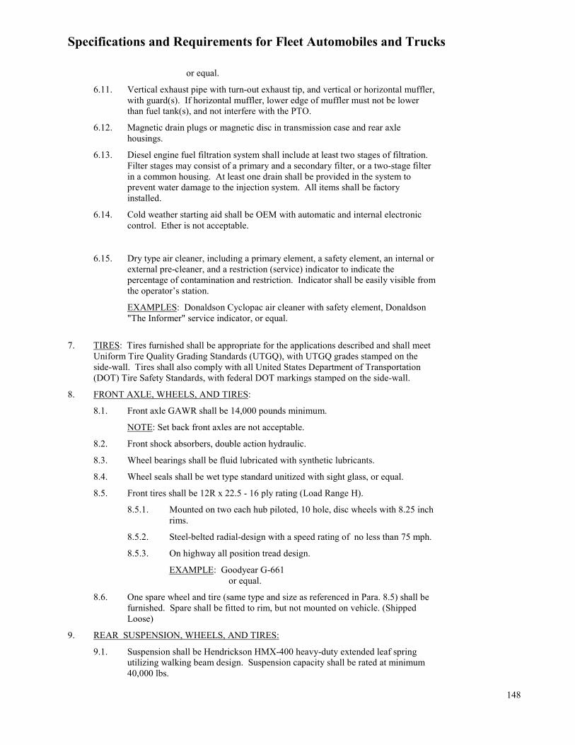
Specifications and Requirements for Fleet Automobiles and Trucks
148
or equal.
6.11. Vertical exhaust pipe with turn-out exhaust tip, and vertical or horizontal muffler, with guard(s). If horizontal muffler, lower edge of muffler must not be lower than fuel tank(s), and not interfere with the PTO.
6.12. Magnetic drain plugs or magnetic disc in transmission case and rear axle housings.
6.13. Diesel engine fuel filtration system shall include at least two stages of filtration. Filter stages may consist of a primary and a secondary filter, or a two-stage filter in a common housing. At least one drain shall be provided in the system to prevent water damage to the injection system. All items shall be factory installed.
6.14. Cold weather starting aid shall be OEM with automatic and internal electronic control. Ether is not acceptable.
6.15. Dry type air cleaner, including a primary element, a safety element, an internal or external pre-cleaner, and a restriction (service) indicator to indicate the percentage of contamination and restriction. Indicator shall be easily visible from the operator’s station.
EXAMPLES: Donaldson Cyclopac air cleaner with safety element, Donaldson "The Informer" service indicator, or equal.
7. TIRES: Tires furnished shall be appropriate for the applications described and shall meet Uniform Tire Quality Grading Standards (UTGQ), with UTGQ grades stamped on the side-wall. Tires shall also comply with all United States Department of Transportation (DOT) Tire Safety Standards, with federal DOT markings stamped on the side-wall.
8. FRONT AXLE, WHEELS, AND TIRES:
8.1. Front axle GAWR shall be 14,000 pounds minimum.
NOTE: Set back front axles are not acceptable.
8.2. Front shock absorbers, double action hydraulic.
8.3. Wheel bearings shall be fluid lubricated with synthetic lubricants.
8.4. Wheel seals shall be wet type standard unitized with sight glass, or equal.
8.5. Front tires shall be 12R x 22.5 - 16 ply rating (Load Range H).
8.5.1. Mounted on two each hub piloted, 10 hole, disc wheels with 8.25 inch rims.
8.5.2. Steel-belted radial-design with a speed rating of no less than 75 mph.
8.5.3. On highway all position tread design.
EXAMPLE: Goodyear G-661 or equal.
8.6. One spare wheel and tire (same type and size as referenced in Para. 8.5) shall be furnished. Spare shall be fitted to rim, but not mounted on vehicle. (Shipped Loose)
9. REAR SUSPENSION, WHEELS, AND TIRES:
9.1. Suspension shall be Hendrickson HMX-400 heavy-duty extended leaf spring utilizing walking beam design. Suspension capacity shall be rated at minimum 40,000 lbs.

Specifications and Requirements for Fleet Automobiles and Trucks
149
9.2. Wheel bearings shall be fluid lubricated with synthetic lubricants.
9.3. Wheel seals shall be wet type standard unitized.
9.4. Rear tires shall be 12R x 22.5 – 16 ply rating (Load Range H).
9.4.1. Mounted on eight each hub piloted, 10-hole, single-piece steel disc wheels with 8.25-inch rims.
9.4.2. Steel-belted radial-design with a speed rating of no more or no less than 75 mph.
9.4.3. On/Off-Highway, open lug design type, with minimum 28/32 tread depth.
EXAMPLE: Goodyear G-282 MSD, Continental HDR2, or equal
9.5. Dust shields (rock guards) shall be provided for each rear axle.
10. BRAKES: Antilock brake system (full vehicle wheel control system, 4S/4M minimum) with air brakes for straight truck application, complete with:
10.1. Compressor, minimum 15 cubic feet per minute.
10.2. Reservoir.
10.3. Low air pressure warning indicator in cab.
10.4. Spring-set type parking brake.
10.5. Tractor package for towing air brake equipped trailers, complete with:
10.5.1. Hand control valve, on steering column or dash mounted in a location easily operated by driver.
10.5.2. Tractor protection valve.
10.5.3. Trailer air couplings.
10.5.4. Electrical cables and seven-wire connector shall be furnished and installed. The cables shall be wired to the connector, in accordance with the American Truck Association’s Maintenance Council recommended practice (RP) 107 as detailed in Vehicle Maintenance Reporting Standards (VMRS) 34-003, latest version. Each wire shall be labeled or a wiring schematic shall be furnished to indicate each wire’s function.
10.5.5. Air brake lines and seven-wire electrical cables shall be routed through the chassis and extend past the end of the frame a sufficient length to allow later installation of a hitch. Air lines and electrical cables shall be affixed past the end of the frame using bulkhead fittings through a steel mounting plate. Lines and cables shall be securely fastened to the frame at intervals sufficient to prevent sagging and to provide clearance of any mechanical parts.
10.5.6. Air dryer – Including integral 100 watt heater, shall be easily accessible, with spin on desiccant cartridge and automatic moisture ejector for air brake system/reservoir(s).
EXAMPLE: Rockwell WABCO System Saver 1200 or equal.
10.5.7. Automatic slack adjusters, front and rear.
10.5.8. Connectors shall be equipped with seals.

Specifications and Requirements for Fleet Automobiles and Trucks
150
EXAMPLE: Midland 10440 seals or equal.
10.5.9. Connectors shall also be equipped with "dummy" glad-hands, to seal rear air lines when not in use.
11. STEERING: Truck shall be equipped with power steering of type normally recommended by manufacturer.
12. CAB: The truck shall have an enclosed cab with a stationary grille. Hood and fender unit shall maintain a minimum 70-degree forward tilt, without contact with the bumper or grille. When gauges are specified, indicator lights are not acceptable. Truck shall be equipped with, but not limited to, the following:
12.1. Cab grab handles.
12.2. Tilt and telescoping steering wheel.
12.3. Tachometer.
12.4. Speedometer.
12.5. Ammeter or voltmeter.
12.6. Oil pressure gauge.
12.7. Engine coolant temperature gauge.
12.8. Fuel gauge.
12.9. Air pressure gauge.
12.10. Electric powered intermittent windshield wipers (air not acceptable) with washers for both sides.
12.11. Air-ride high back driver and passenger seat.
EXAMPLE: National Cush-N-Aire or equal
12.12. Dual sun visors.
12.13. Fresh air type heater and defroster.
12.14. Air conditioner, factory installed.
12.15. Power adjustable, heated, exterior side view mirrors, OEM framed, break-away, west-coast rearview type, left and right sides. The mirrors shall have auxiliary convex mirrors (not stick-on type).
12.16. Two hood-mounted, convex mirrors for left and right side.
12.17. Hourmeter, either of the following types are acceptable:
12.17.1. OEM, factory installed and integrated into an electronic instrument display system.
12.17.2. Aftermarket, electric quartz, shock proof, totally sealed case, with readout up to 9,999.9 hours. Three screw or flush mount to accommodate equipment system voltage range between 10-80V.
EXAMPLE: Hobbs Model 85001-02 or equal
12.18. Four additional dash-mounted, two position toggle (on/off) switches, with power supplied to each switch. Power to switches shall be supplied from an easily accessible power strip or junction box located in the cab. Each terminal on power strip or junction box shall be supplied with power and each circuit protected by a minimum 20 amp manual or automatic reset circuit breaker(s) (SAE type III with

Specifications and Requirements for Fleet Automobiles and Trucks
151
trip indicators). Switches shall be factory installed if available from the OEM.
12.19. AM-FM radio, chassis factory-installed standard brand. Antenna, which may be an integral part of the windshield, shall be furnished and mounted.
12.20. Two entry steps shall be provided on each side of the cab. Anti-skid surface shall be furnished on entry steps.
12.21. Hood mounted left and right side convex mirrors, minimum 7.4 square inches.
12.22. Power Locks and Windows.
12.23. One set of DOT and Federal Motor Vehicle Safety Standard approved triangle reflective kit.
12.24. High visibility colored seatbelts, orange colored, for both driver and passenger seats. Seatbelt covers are not acceptable.
13. TRUCK: The truck shall be equipped to include, but not be limited to, the following:
13.1. Directional signals with flasher, visible from front and rear.
13.2. LED type clearance lights and reflectors meeting Texas Motor Vehicle Laws and Texas Department of Public Safety Requirements.
13.3. Front fenders and bumper.
13.4. Front tow hooks.
13.5. Radiator protector/stone guard shall be behind or integral with the front grille.
13.6. License plate brackets, front and rear, with illuminating light on rear bracket.
13.7. Twin air horns, if available from OEM, or single trumpet air horn if twin air horns are not available.
13.8. Sealed beam or halogen headlights.
14. RADIO FREQUENCY (RF) INTERFERENCE SUPPRESSION: The vehicle and allequipment and components mounted to the chassis shall incorporated RF interferencesuppression so as to provide RF interference immunity to and from land mobile radiotransceivers operating in the following bands: High Frequency (2 to 30 MHZ), Low band(30 to 50 MHZ), high band (140 to 174 MHZ), UHF band (440 to 512 MHZ), and the700/800/900 MHZ band (700 to 975 MHZ), and comply with the following requirements:
14.1. Typical land mobile radio transceivers will utilize a 3dB gain antenna with up toa 125 watt RF power output. Antennas will be mounted on the roof, front fender, and/or rear fender of the unit.
14.2. VEHICLE COMPONENT RF SUPRESSION: All equipment electronic circuits shall be designed to suppress, bypass, or otherwise prevent interference from affecting the radio transceiver. The RF immunity requirement shall apply to all Contractor supplied equipment and components thereof including, but not limited to, ignition, AM/FM radio receivers, computers, emission controls, fuel pumps, wiper motors, alternative fuel electronic components, air bag systems, and ABS controllers, etc.
14.3. VEHICLE COMPONENT RF IMMUNITY: The vehicle electronic equipment including, but not limited to, ignition, AM/FM radio receivers, computers, emission controls, fuel pumps, wiper motors, alternative fuel electronic components, air bag systems, and ABS controller, shall not be adversely affected in operation, safety, or control by radio frequency (RF) energy generated and radiated by the transmitter portion of installed transceivers (up to 125 watt output).
14.4. When available from the OEM, Dealer shall provide OEM's RFI ordering code designation.

Specifications and Requirements for Fleet Automobiles and Trucks
152
14.5. Contractor will be assessed any and all charges associated with the testing and remediation of vehicles which fail to meet RFI requirements at any time during the warranty period.
15. FUEL TANK: Shall be equipped with one each Federal Motor Carrier Safety Administration (FMCSA) approved frame mounted safety fuel tank with a total minimum 80-gallon capacity. Tank shall be mounted on the left or right side of the unit, and shall not interfere with dump bed operation. Shall include all necessary valves, hoses, and gauges.
16. PAINTING: The unit shall be painted an approved manufacturer's standard lead free bright white color, except for glass, rubber, and those metallic accessories or fixtures constructed of rust-resistant or plated material not normally painted.
17. MANUAL(S): Original manual(s) in paper format or electronic version access without fee based subscription shall be delivered with the unit. It is requested but not required that the manual be printed on recycled paper. Manuals shall include:
17.1. An illustrated parts list(s) coving all components of the unit identifying parts by part number, description, and component location.
17.2. Hydraulic schematics.
17.3. Electrical schematics.
17.4. All necessary operating instructions and maintenance procedures for the unit and engine(s).
17.5. The following additional information shall be provided by the Contractor at time of delivery if not included in the manual required above.
17.5.1. Manufacturer’s recommended service and preventive maintenance intervals.
17.5.2. Recommended fluids, lubricants, and their SAE or API equivalents.
18. PARTS AND SERVICE: The manufacturer of the equipment furnished shall have an authorized dealer within the state of Texas. The authorized dealer shall have factory-trained personnel available for warranty repairs and the performance of service. The dealer shall also maintain an inventory of high-usage parts and a quick source for low-usage parts, which shall be available within three working days after ordering.
19. MANUFACTURER’S STATEMENT OF ORIGIN (MSO): Contractor shall furnish a MSO and a Weight Slip (if applicable) for each unit to the receiving district with each unit at time of delivery. CUSTOMER WILL NOT ACCEPT THE UNIT AND PROCESS PAYMENT WITHOUT THE MSO.
20. TITLE APPLICATION FORM: Contractor shall furnish a completed State of Texas Form 130-U, Application for Texas Title and/or Registration, to the receiving district with each unit at time of delivery. The Form 130-U must be the most current version available. TxDOT WILL NOT ACCEPT THE UNIT AND PROCESS PAYMENT WITHOUT THE COMPLETED FORM 130-U.
OPTIONAL EQUIPMENT
Optional equipment must be identified on the PO to be required.
NOTE: Welding to the truck frame is not acceptable. Hole drilling shall be confined to the vertical face of the truck frame.
1. OPTION NO. 1.1 – FRONT FRAME EXTENSIONS: Truck shall be equipped with factory integral front frame extensions measuring a minimum 24 inches from the front bumper. The exact length will be identified on the PO.

Specifications and Requirements for Fleet Automobiles and Trucks
153
2. OPTION NO. 1.2 – SET-BACK FRONT AXLE: Truck shall be equipped with manufacturers standard set-back axle configuration, minimum 14,000 pound GAWR, in lieu of paragraph 7.1.

Specifications and Requirements for Fleet Automobiles and Trucks
154
SERIES 1200D
TRUCK TRACTOR CAB/CHASSIS 6-CYLINDER DIESEL
TANDEM AXLE
SPECIFICATIONS
1. SCOPE: This specification describes a tandem-axle diesel-powered truck tractor cab and chassis for use by TxDOT to pull van trailers, machinery trailers, float trailers, or other trailers as needed. Truck tractor(s) furnished to this specification shall be legally and structurally capable of transporting the specified GVWR and GCWR requirements, on highway, at speeds up to 70 MPH and off highway under conditions imposing more severe frame stresses without experiencing failure or permanent sets in the truck frame or any component of the unit. All specified components shall be OEM, factory installed, when offered by the vehicle manufacturer. Aftermarket components are subject to TxDOT approval. Unit(s) furnished to this specification shall meet or exceed all requirements. EXAMPLES: Freightliner M2-112
International 7600 6x4 Volvo VNM 64T300 Mack Pinnacle Western Star 4700 SA or equal.
NOTICE TO RESPONDENT: Any example shown is listed to show type and class of equipment desired. Respondent is cautioned to read the specification carefully, as there may be special requirements not commonly offered by the equipment manufacturer. DO NOT ASSUME STANDARD EQUIPMENT MEETS ALL DETAILED SPECIFICATIONS MERELY BECAUSE IT IS LISTED AS AN EXAMPLE. Respondent is cautioned that any unit delivered to the Freight on Board (FOB) point that does not meet specifications in every aspect will not be accepted.
2. CHASSIS: Tandem-axle, diesel-powered cab and chassis, shall meet the following requirements:
2.1. Gross vehicle weight rating (GVWR) shall be minimum 52,000 pounds.
2.2. Gross combination weight rating (GCWR) shall be minimum 80,000 pounds.
2.3. Chassis, components, and accessories (including after-market or non-OEM up-fits) shall comply with all applicable Technology and Maintenance Council (TMC) recommended practices.
2.4. Wheelbase: 160 to 185 inches.
2.5. Cab to center line of tandem dimension shall be 117 to 124 inches.
2.6. Frame shall be minimum 1,500,000 Resistance bending moment (RBM) from behind the cab to within 3 inches of the end of the frame.
3. PERFORMANCE REQUIREMENTS: The driveline components offered shall provide the following minimum performance in the intended application:
3.1. Engine, transmission, and axle ratio shall be capable of attaining a minimum geared speed of 80 mph before the governed engine rpm is reached.
3.2. Maximum vehicle speed in top gear shall be electronically limited or governed to 65 mph.
3.3. Maximum cruise control speed setting shall be electronically set at 65 mph.
3.4. A minimum 1.1% percent grade ability at 60 mph, steady state, based upon 80,000 pound GCWR.
3.5. A minimum 15% percent startability from a complete stop, based upon 80,000 pound GCWR.
3.6. Provide a gradeability and startability printout verifying the driveline

Specifications and Requirements for Fleet Automobiles and Trucks
155
configuration offered meets all specified requirements.
Documentation shall be with the solicitation, or provided within five days from request, and prior to purchase order award. TxDOT will make the final determination on acceptability of a proposed drivetrain, and it’s suitability for the intended application.
4. DRIVELINE COMPONENTS: Driveline components shall meet the following minimum requirements:
4.1. Engine shall be electronically controlled diesel, in-line 6-cylinder design, minimum of a 12 liter and shall have:
4.2. Minimum 470 SAE gross horsepower
4.3. Minimum 1,650 lbs./ft. peak torque.
4.4. Engine shall be manufactured by and branded as a product of Cummins, Navistar, Volvo, Mack, PACCAR, or Detroit Diesel. Only engines from these manufacturers are acceptable. Engine repairs shall be available at any facility authorized as a repair provider by the applicable engine manufacturers.
4.5. Transmission shall have a minimum 13 forward gears and 3 reverse gears, fully automated transmission with an electronically actuated clutch. This transmission should allow full clutch engagement at idle, auto neutral, hill start aid to use foundation brakes to prevent roll back or roll forward and provide a creep mode for low speed operation. This transmission must be suitable for the applications described in this TxDOT specification Paragraph 1, and shall meet the performance requirements in the this TxDOT specification Paragraph 3.1 through 3.6
EXAMPLE: Eaton UltraShift Plus MHP or equal.
5. DRIVELINE AND ENGINE ACCESSORIES: All accessories necessary for operation shall be provided, to include, but not limited to, the following:
5.1. Transmission must have power take-off (PTO) provisions.
5.2. Electric starting motor.
5.3. BATTERY(IES): Sealed, spill-proof, absorbed glass mat (AGM) type (no free electrolyte), maintenance-free battery with sufficient cold cranking amperes (CCA) total battery rating to reliably start the unit in zero degree Fahrenheit weather. Shall be covered by minimum 12 month full replacement warranty and minimum 36 month prorated warranty. Replacement battery shall be furnished by Contractor during 12 month initial warranty period at no cost (including shipping or environmental fees) to TxDOT. EXAMPLE: Optima YellowTop or equal
5.4. Battery disconnect switch used to shut down the entire battery fed electrical system with the exception of the ECM or any other device requiring constant electrical power. Switch shall be located in the cab and accessible from driver’s door at street level.
5.5. Heavy-duty 12-volt alternator rated at minimum 200 amperes.
5.6. Oil pump.
5.7. Full-flow type oil-filtration system with replaceable filter and provision for bypassing oil to the engine as the filter becomes clogged.
5.8. Manufacturers recommended dry type air filter, dual or two-stage.
5.9. Heavy-duty radiator, maximum cooling capacity offered by manufacturer.

Specifications and Requirements for Fleet Automobiles and Trucks
156
5.10. Ethylene Propylene Diene Monomer (EPDM) or silicone radiator hoses and water lines.
5.11. OEM standard extended life coolant.
5.12. Automatic or viscous fan clutch.
5.13. Vertical exhaust with turn outs, and vertical or horizontal muffler, with guard(s). If horizontal muffler, lower edge of muffler must not be lower than fuel tank(s).
5.14. Magnetic drain plugs in transmission case and rear axle housing.
5.15. Diesel engine fuel filtration system shall include a minimum of two stages of filtration. Filter stages may consist of a primary and a secondary filter, or a two stage filter in a common housing. Drain plug(s) shall be provided to prevent water damage to the injection system. All items shall be factory approved and factory installed.
5.16. Cold weather starting aid shall be OEM with automatic and internal electronic control. Ether is not acceptable.
5.17. 115 Volt engine block heater.
EXAMPLE: Hotstart, Model CNT-151B.
6. TIRES: Tires furnished shall be appropriate for the applications described. Tires shall meet Uniform Tire Quality Grading Standards (UTGQ), with UTGQ grades stamped on the side-wall. Tires shall also comply with all US DOT Tire Safety Standards, with federal DOT markings stamped on the side-wall.
7. FRONT AXLE, SPRINGS, WHEELS, AND TIRES
7.1. Shock absorbers, front double action hydraulic.
7.2. Front axle GAWR shall be minimum 12,000 pounds.
7.3. Wheel bearings shall be sealed hub or fluid lubricated with synthetic lubricants.
7.4. Oil seals shall be wet-type, two-piece with sight glass.
EXAMPLE: STEMCO or equal.
7.5. Front tires shall be 11R x 22.5 14-ply rating (Load Range G).
7.5.1. Steel-belted radials with all-position, on-highway tread.
7.5.2. Mounted on 10-hole, hub piloted steel disc wheels with 8.25 inch rims.
EXAMPLE: Goodyear G-661 HSA or equal.
8. REAR AXLE, SUSPENSION, WHEELS, AND TIRES
8.1. Rear axle shall be full tandem drive, with a minimum 40,000 pound rear GAWR. Tandem shall be single speed, single reduction with inter-axle differential and power divider lockout, or single speed, double reduction with automatic power divider system.
8.2. A rear axle ratio shall be used that will meet the performance requirements listed in Part II, Para. 3. and must be approved by TxDOT prior to build.
8.3. Rear suspension shall be a 40,000 lb. air ride with single leveling valves and dash mounted dump valve.
8.4. Wheel bearings shall be fluid lubricated with synthetic lubricant.
8.5. Oil seals shall be wet-type, two-piece.

Specifications and Requirements for Fleet Automobiles and Trucks
157
EXAMPLE: STEMCO or equal.
8.6. Rear tires shall be 11R x 22.5 14-ply rating (Load Range G).
8.6.1. Steel-belted radials with all position on-highway tread.
8.6.2. Mounted on 10-hole, hub piloted steel disc wheels with 8.25 inch rims.
EXAMPLE: Goodyear G-661 HSA or equal.
8.7. One spare wheel and tire (same type and size as referenced in Para. 7.5.) shall be furnished. Spare shall be fitted to rim, but not mounted on vehicle.
8.8. Dust shields (rock guards) shall be provided for each rear axle.
9. BRAKES: Air, dual system with Antilock brake System (ABS) (full vehicle wheel control system, 4S/4M) with air brakes for tractor truck application, complete with:
9.1. Compressor, minimum 15 cubic feet.
9.2. Parking Brake Alarm
9.3. Air reservoir.
9.4. Air dryer – Including integral 100 watt heater, shall be easily accessible, with easily replaceable desiccant cartridge with automatic and manual drain features.
9.5. Connectors shall be equipped with seals. EXAMPLE: Midland 10440 seals or equal.
9.6. Parking brake shall be spring-set type.
9.7. Tractor package for towing air brake equipped trailers, complete with:
9.7.1. Hand control valve, on steering column or dash mounted in a location easily operated by driver.
9.7.2. Tractor protection valve as specified by the Federal Motor Carrier Safety Association (FMCSA).
9.7.3. Trailer air couplings with a service brake coupler and a red colored emergency brake coupler. Couplings shall also be equipped with “dummy” glad-hands to seal rear air lines when not in use.
9.7.4. A spring assisted post will be used to prevent hoses and all wires going to trailer from tangling, stretching or contacting driveline or other moving parts when making turns.
9.8. Electrical cables and 7-wire connector shall be furnished and installed. The cables shall be wired to the connector, in accordance with the American Truck Association’s Maintenance Council recommended practice (RP) 107B as detailed in Vehicle Maintenance Reporting Standards (VMRS) 34-003, latest version. Each wire shall be labeled or a wiring schematic shall be furnished to indicate each wire’s function.
10. FIFTH WHEEL: Cast steel, 36 inches. Fifth wheel shall be mounted four inches forward of the center of the tandem. Safety latch location is at Contractor's option, mounted on driver’s side of unit. Aluminum grate catwalk shall be furnished and mounted in front of fifth wheel.
10.1. Air sliding type fifth wheel, complete with in cab controls. Mounted so that the forward-most position of king pin is 15 inches forward of the center line of the tandem. Slide rack travel length shall be minimum 36 inches. Shall be mounted within 46 to 49 inches from ground, unless otherwise specified.

Specifications and Requirements for Fleet Automobiles and Trucks
158
10.2. Shall provide minimum 84” swing clearance for trailer goose neck or landing gear.
10.3. A catwalk made of aluminum grate and access steps shall be provided and installed between the truck frame rails behind the cab and run up to the fifth wheel and shall provide the operator a place to stand while making hydraulic, electrical and pneumatic connections. Catwalk will be mounted as to not contact trailer while traversing uneven terrain.
11. STEERING: Truck shall be equipped with power steering of type normally recommended by manufacturer.
12. CAB: The truck shall have an enclosed conventional cab. Total distance from front of truck to rear of the cab (BBC) shall not exceed 116 inches. Truck shall also be equipped with, but not be limited to, the following (Note: When gauges are specified, indicator lights are not acceptable):
12.1. Cab grab handle providing three-point contact and access steps. Steps shall have anti-skid type surface. Grab handles and steps shall be positioned so the operator, when entering or exiting, will maintain a three-point contact with the unit at all times.
12.2. Shatterproof tinted windshield and door glass.
12.3. Engine tachometer.
12.4. Speedometer.
12.5. Engine hourmeter, OEM type accessible through instrument cluster.
12.6. Ammeter or voltmeter.
12.7. Oil pressure gauge.
12.8. Engine coolant temperature gauge.
12.9. Fuel gauge.
12.10. Tilt and telescoping steering wheel.
12.11. Pre-Trip Light Inspection.
12.12. Air pressure gauge.
12.13. One set of D.O.T. and FMVSS approved triangle reflective kit.
12.14. Low air pressure warning indicator in cab with an audible and visible alarm.
12.15. Electric powered (air not acceptable) intermittent type windshield wipers, with washers for both sides.
12.16. Air-ride high back driver and passenger seat. Both driver and passenger seat belts shall be OEM installed high visibility orange colored. Seatbelt covers are not acceptable.
EXAMPLE: National Cush-N-Aire or equal
12.17. Dual sun visors.
12.18. Fresh-air type heater and defroster.
12.19. Air Conditioner, manufacturer’s standard, factory installed.
12.20. Two hood mounted, convex mirrors for left and right side, minimum 7.4 square inches.
12.21. Contractor shall install after-market deep window tint, the maximum legal tint on

Specifications and Requirements for Fleet Automobiles and Trucks
159
driver, passenger, and rear windows. Must be TxDOT pre-approved prior to installation. Examples to be furnished to TxDOT representative.
12.22. OEM Power adjustable, heated, framed, break-away, exterior side view mirrors. Shall be west-coast rearview type, left and right sides. The mirrors shall have auxiliary convex mirrors (not stick-on type).
12.23. OEM Power locks and power windows shall be provided.
12.24. AM/FM radio with weather band (Wx) feature. Shall be factory-installed, manufacturer’s standard-brand transistor radio. Antenna, which may be an integral part of the windshield, shall be furnished and mounted.
12.25. Units shall be equipped with the following to facilitate entity mounting of ancillary equipment integral in the vehicle electrical system shall be installed by the OEM as either standard or optional equipment: Four dash mounted toggle (on/off) switches with power source to each switch. Power to switches shall be supplied from an easily accessible power strip or junction box. Each terminal on the power strip or junction box shall be supplied with power and each circuit protected by a minimum 20 amp manual or automatic reset circuit breaker(s) – SAE type III with trip indicators. Switches shall be factory installed if available from the OEM.
13. TRUCK: The truck shall be equipped to include, but not be limited to, the following:
13.1. Where available, all exterior lights shall be L.E.D. type with the exception of the headlights.
13.2. Daytime Running lights.
13.3. Clearance lights, reflectors, and identification lights meeting Texas Commercial Motor Vehicle Laws and Texas Department of Public Safety Requirements.
13.4. Front fenders and bumper.
13.5. Front mounted, behind grille bug screen.
13.6. Back-up Alarm system with audible exterior alarm.
13.7. Radiator protector or stone guard shall be behind or integral with, the front grille.
13.8. Metal license plate brackets with illuminating light on rear bracket.
13.9. Tow devices – Front and rear tow hooks, “D” rings or tow pins.
13.10. Twin Air horns, if available from OEM, or single trumpet air horn if twin air horns are not available.
13.11. Rear quarter fenders mounted forward of the tandem axles and mud flaps mounted behind the tandem axles, with anti-sail and anti-spray mud flaps spring mounted with Betts brackets (or equal) Mud flaps shall reach to within eight inches of the ground. NOTE: Advertisements are not permitted on mud flaps.
13.12. Rear mounted camera wired to in-cab seven inch monitor. Camera shall be able to operate automatically when in reverse and operator shall have the option to operate in forward gear. Camera shall be mounted on the headache rack on trucks equipped with headache rack and on the rear of the cab on trucks without a headache rack. EXAMPLE: Zone Defense, Model# ZD.323.1.15CH.or equal
13.13. Minimum of two white, halogen, high-low sealed beam headlights. Headlights shall be mounted one on each side on the front of the unit. Headlights shall automatically turn on when windshield wipers are activated.
13.14. An extra circuit breaker shall be provided in the fuse panel for protection of the

Specifications and Requirements for Fleet Automobiles and Trucks
160
semi-trailer electrical system.
14. RADIO FREQUENCY (RF) INTERFERENCE SUPPRESSION: The vehicle and allequipment and components mounted to the chassis shall incorporate RF interferencesuppression so as to provide RF interference immunity to and from land mobile radiotransceivers operating in the following bands: : High Frequency (2 to 30 MHZ), Low band(30 to 50 MHZ), high band (140 to 174 MHZ), UHF band (440 to 512 MHZ) and the700/800/900 MHZ band (700 to 975 MHZ) and comply with the following requirements:
14.1. Typical land mobile radio transceivers will utilize a 3dB gain antenna with up to a125 watt RF power output. Antennas will be mounted on the roof, front fender, and/or rear fender of the unit.
14.2. VEHICLE COMPONENT RF SUPRESSION: All equipment electronic circuits shall be designed to suppress, bypass or otherwise prevent interference from affecting the radio transceiver. The RF immunity requirement shall apply to all Contractor supplied equipment and components thereof including, but not limited to, ignition, AM/FM radio receivers, computers, emission controls, fuel pumps, wiper motors, alternative fuel electronic components, air bag systems, and ABS controllers, etc.
14.3. VEHICLE COMPONENT RF IMMUNITY: The vehicle electronic equipment including, but not limited to, ignition, AM/FM radio receivers, computers, emission controls, fuel pumps, wiper motors, alternative fuel electronic components, air bag systems, and ABS controller, shall not be adversely affected in operation, safety, or control by radio frequency (RF) energy generated and radiated by the transmitter portion of installed transceivers (up to 125 watt output).
14.4. When available from the OEM, Dealer shall provide OEM's RFI ordering code designation
14.5. Contractor will be assessed any and all charges associated with the testing and remediation of vehicles which fail to meet RFI requirements at any time during the warranty period.
15. FUEL TANKS
15.1. Fuel Tank shall be equipped with one each Federal Motor Carrier SafetyAdministration (FMCSA) approved frame mounted safety fuel tank with a total minimum 100-gallon capacity. If dual tanks are provided, they shall be top draw type; cross-over fuel line shall not be utilized. Tank arrangement shall not interfere with tractor-trailer operation.
15.2. Fuel system shall include all valves, gauges, etc. necessary for operation.
16. PAINTING: The unit shall be painted with a manufacturer's standard lead-free whitecolor, except for glass, rubber and those accessories or fixtures constructed of rust-resistantor plated material not normally painted.
17. SAFETY INSPECTION: The unit shall be in compliance with Texas Commercial MotorVehicle Laws upon delivery, and be ready for inspection and certification by a licensedinspection station.
18. MANUALS: Original manual(s) in paper format or electronic version access without feebased subscription shall be delivered with the unit. It is requested but not required that themanual be printed on recycled paper. Manuals shall include
18.1. An illustrated parts list(s) coving all components of the unit identifying parts bypart number, description and component location
18.2. Hydraulic schematics
18.3. Electrical schematics

Specifications and Requirements for Fleet Automobiles and Trucks
161
18.4. All necessary operating instructions and maintenance procedures for the unit and engine(s)
18.5. The following additional information shall be provided by the Contractor at time of delivery if not included in the manual required above.
18.5.1. Manufacturer’s recommended service and preventive maintenance intervals
18.5.2. Recommended fluids, lubricants and their SAE or API equivalents
19. MANUFACTURER'S STATEMENT OF ORIGIN (MSO): Contractor shall furnish MSO for each unit. MSO shall be executed in the name of the Customer. Should order be for, it shall be executed in the name of Texas Department of Transportation and mailed to:
Texas Department of Transportation, Fleet Operations Division Attn: Fleet Acquisitions 3500 Jackson Ave, Bld. 10 Austin, Texas 78731
CUSTOMER WILL NOT ACCEPT THE UNIT AND PROCESS PAYMENT WITHOUT THE MSO.
20. TITLE APPLICATION FORM: Contractor shall furnish a completed State of Texas Form 130-U, Application for Texas Title and/or Registration, to the receiving district with each unit at time of delivery. The Form 130-U must be the most current version available.
TxDOT WILL NOT ACCEPT THE UNIT AND PROCESS PAYMENT WITHOUT THE COMPLETED FORM 130-U.
OPTIONAL EQUIPMENT
Optional equipment must be identified on the PO to be required. NOTE: Welding to the truck frame is not acceptable. Hole drilling shall be confined to the vertical face of the truck frame.
1. OPTION NO. 1: HEADACHE RACK – Aluminum, Heavy-duty, constructed as normally furnished with a truck of this size. Headache rack shall be bolted to frame and include a chain tray, chain rack, and window with jailbars. Headache rack shall include a riser which will extend the height of the cab and include a top mount light bar pad measuring approximately 51” wide so that a light bar can be added by TxDOT personnel. In lieu of spring assisted post in Para. 9.8.4 a swinging hose hanger bar may be provided.
2. OPTION NO. 2: WET KIT/PTO/PUMP – Unit shall have a wet kit so that hydraulic power can be provided to transport trailers. The wet kit shall be provided and installed and must include:
2.1. An inline relief valve to prevent pressure build-up if trailer lines are not properly connected.
2.2. A transmission mounted PTO and direct mount pump shall be installed on the truck transmission. The pump shall be supported with an external pump support bracket mounted to the transmission. PTO shall be provided that is clutch shift or “hot shift” type and rated for use with the automatic transmission required for this application. The pump shall be capable of 15 to 25 gpm via a flow control valve, and shall provide a minimum 2400 psi hydraulic pressure.
2.2.1. The pump shall be controlled through a speed device that will automatically engage the pump at the proper engine RPM and will not allow engagement unless the engine is under 750 RPM and the truck transmission is in the neutral position. A gear type pump shall be provided with a bypass/pressure relief valve that is plumbed back to reservoir.
2.2.2. Dash mounted PTO controls shall include: Switch for electric/air solenoid, PTO hour meter, and “PTO engaged” light. Shall include all associated wiring and piping.
2.2.3. PTO/Pump shall automatically disengage when the RPM exceeds manufacturer’s recommended RPM.

Specifications and Requirements for Fleet Automobiles and Trucks
162
2.2.4. All valves, fittings, lines, filters, and quick coupler connections necessary for trailer operation shall be included and installed.
2.1. An aluminum, saddle style, dual port, hydraulic reservoir shall be mounted behind cab and be a minimum of 50 gallon capacity.
2.2. Wet kit shall be filled to capacity with SAE 10 hydraulic oil meeting MIL-L-46152 specifications. Hoses will remain with truck when disconnected from trailer and will be long enough to allow maximum articulation of truck and trailer without stretching. A spring assisted post will be used to prevent hoses and all wires going to the trailer from tangling, stretching or contacting drive line or other parts. One-quarter (1/4) turn ball valves will be installed to isolate the reservoir (suction and return lines) for service and maintenance.

Specifications and Requirements for Fleet Automobiles and Trucks
163
SERIES 1202D TRUCK/TRACTOR, 6-CYLINDER
DIESEL-POWERED TANDEM AXLE
50,000 GVWR TEXAS DEPARTMENT OF CRIMINAL JUSTICE
Item TX Minimum Requirements International Freightliner VOLVO
Body Trim Designation (Base Vehicle) Per R1084284 ProStar Cascadia
CA125DC-Day Cab
VNL64T300 GVWR, pounds 52,000 52000 53220 52000 GCWR, pounds As Shown 80000 80000 110000 Front GAWR, pounds 12,000 12000 13300 12000 Rear GAWR, pounds 40,000 40000 40000 40000 Wheelbase, inches 225 226 242 225 BBC (Bumper to Back of Cab) 121.6 121.9 126 121.6
Front Axle Capacity, pounds 12,000 12000 13300 12000
Rear Axle Capacity, pounds 40,000 40000 40000 40000 Set Back Front Axle 49 50.2 49 51.1 Heavy-Duty Frame, RBM As Shown 1782000 1808400 1778400 Diesel Engine Displacement, liters
Diesel In-Line 6 12.4L 14.8L 13L
Horse power SAE 475 475 485 475 Torque, SAE lbs-ft 1,650 1700 1650 1650 Governed Speed, RPM As Shown 1900 1900 RPM 75 at 1620 RPM Transmission, Manual Standard (RTLO-16913A) 13 Speed 13 Spd 13 Spd RTLO-
16913A 13 Spd RTLO
16913A Tire Size & Load Range 11R24.5 14PLY 11R24.5 14 Ply 11R24.5 14 PLY 11R24.5 14 PLY Rim Size, inches As Shown 8.25 8.25 8.25 Alternator, amperes As Shown 160 160 165

Specifications and Requirements for Fleet Automobiles and Trucks
164
SERIES 1286D TRUCK TRACTOR, TANDEM AXLE
WITH PUSHER DIESEL-POWERED
86,000 GVWR
SPECIFICATIONS
1. SCOPE: This specification describes a tandem-axle, with pusher axle, diesel-powered truck tractor cab and chassis for use by TxDOT to pull van trailers, machinery trailers, float trailers or other trailers as needed. Truck tractor(s) furnished to this specification shall be legally and structurally capable of transporting the specified GVWR and GCWR requirements, on highway, at speeds up to 70 MPH and off highway under conditions imposing more severe frame stresses without experiencing failure or permanent sets in the truck frame or any component of the unit. All specified components shall be original equipment manufacturer (OEM), factory installed, when offered by the vehicle manufacturer. Aftermarket components require TxDOT approval. Unit(s) furnished to this specification shall meet or exceed all requirements. EXAMPLES: Freightliner 122SD International HX Volvo VNX 300 Mack Titan Western Star 4900
or equal
NOTICE TO RESPONDENT: Any example shown is listed to show type and class of equipment desired. Respondent is cautioned to read the specification carefully, as there may be special requirements not commonly offered by the equipment manufacturer. DO NOT ASSUME STANDARD EQUIPMENT MEETS ALL DETAILED SPECIFICATIONS MERELY BECAUSE IT IS LISTED AS AN EXAMPLE. Respondent is cautioned that any unit delivered to the FOB point that does not meet specifications in every aspect will not be accepted.
2. CHASSIS: Tandem-axle, with pusher axle, diesel-powered cab and chassis
2.1. Chassis, components, and accessories (including after-market or non-OEM up-fits) shall comply with all applicable Technology and Maintenance Council (TMC) recommended practices.
2.2. Minimum 86,000 pounds GVWR and 160,000 pounds GCWR.
2.3. Wheelbase: 235 to 270 inches.
NOTE: Dimensions may be adjusted to maintain effective cab to center line of tandem dimension. Wheelbase must be approved by TxDOT prior to production.
2.3. Cab to center line of tandem dimension shall be 133 to 168 inches.
2.5. Frame shall be minimum 3,200,000 RBM from behind the cab to within 3 inches of the end of the frame.
3. PERFORMANCE REQUIREMENTS: The driveline components offered shall provide the following minimum engine performance in the intended application:
3.1. Engine, transmission and rear axle ratio shall be capable of attaining a minimum geared speed of 80 mph before the governed engine rpm is reached.
3.2. Maximum vehicle speed in top gear shall be electronically limited or governed to 65 mph.
3.3. Cruise shall be provided, and be electronically set at 60 mph.

Specifications and Requirements for Fleet Automobiles and Trucks
165
3.4. Shall provide minimum 1.1 percent gradeability at 55 mph, steady state at cruise speed, based upon 86,000 lbs. GVWR, 120,000 lbs. GCWR.
3.5. Shall provide minimum 15 percent startability from a complete stop (at clutch engagement), based upon 86,000 lbs. GVWR, 160,000 lbs. GCWR.
3.6. Respondent should submit a gradeability and startability printout with the response. This information is required prior to award. Failure to provide this information with the response or, within 3 working days of written request will result in the response being considered non-responsive.
4. DRIVELINE COMPONENTS: Driveline components shall meet the following minimum requirements:
4.1. Engine shall be electronically controlled diesel, in-line 6-cylinder design. Shall have minimum 500 SAE gross horsepower and minimum 1,850 foot pounds gross torque. Engine shall be manufactured by and branded as a product of Cummins, Navistar, Detroit Diesel, Volvo, Caterpillar, Mack or PACCAR. Only engines from these manufacturers are acceptable. Engine repairs shall be available at any facility authorized as a repair provider by the applicable engine manufacturers.
4.2. Transmission shall have a minimum 18 forward gears and 4 reverse gears, fully automated transmission with an electronically actuated clutch. This transmission should allow full clutch engagement at idle, auto neutral, hill start aid to use foundation brakes to prevent roll back or roll forward and provide a creep mode for low speed operation. This transmission must be rated for operation at a minimum 160,000 Lbs. GCWR, suitable for the applications described in Part II, Para. 1., and shall meet the performance requirements in Part II, Para. 3.1. through 3.5.
EXAMPLE: Eaton UltraShift PLUS model MXP 18B or equal
5. DRIVELINE AND ENGINE ACCESSORIES: All accessories necessary for operation shall be provided, to include, but not limited to, the following:
5.1. SAE 6-bolt and 8-bolt power take-off (PTO) access openings in transmission.
5.2. Electric starting motor.
5.3. BATTERY(IES): Sealed, spill-proof, absorbed glass mat (AGM) type (no free electrolyte), maintenance-free battery with sufficient cold cranking amperes (CCA) total battery rating to reliably start the unit in zero degree Fahrenheit weather. Shall be covered by minimum 12 month full replacement warranty and minimum 36 month prorated warranty. Replacement battery shall be furnished by Contractor during 12 month initial warranty period at no cost (including shipping or environmental fees) to TxDOT.
EXAMPLE: Optima YellowTop or equal.
5.4. Battery disconnect switch used to shut down the entire battery fed electrical system. Shall be located in cab and accessible from street level, driver’s door.
5.5. Heavy-duty 12-volt alternator rated at minimum 160 amperes.
5.6. Oil pump.
5.7. Full-flow type oil-filtration system with replaceable filter and provision for bypassing oil to the engine as the filter becomes clogged.
5.8. Manufacturers recommended dry type air filter, dual or two-stage.
5.9. Heavy-duty radiator, maximum cooling capacity offered by manufacturer.

Specifications and Requirements for Fleet Automobiles and Trucks
166
5.10. Ethylene Propylene Diene Monomer (EPDM) or silicone radiator hoses and water lines.
5.11. OEM standard extended life coolant.
5.12. Automatic or viscous fan clutch.
5.13. 110 Volt engine block heater
EXAMPLE: Hotstart, Model CNT1515 or equal.
5.14. Vertical exhaust, and vertical or horizontal muffler, with guard(s) and rain cap(s). If horizontal muffler, lower edge of muffler must not be lower than fuel tank(s), and not interfere with the PTO.
5.15. Magnetic drain plugs in transmission case and rear axle housing.
5.16. Diesel engine fuel filtration system shall include a minimum of two stages of filtration. Filter stages may consist of a primary and a secondary filter, or a two stage filter in a common housing. Drain plug(s) shall be provided to prevent water damage to the injection system. All items shall be factory approved and factory installed.
5.17. Cold weather starting aid shall be integral with internal electronic control, or manual with in-cab controls.
6. TIRES: Tires furnished shall be appropriate for the applications described and be of high quality design, materials, and workmanship. Tires shall meet Uniform Tire Quality Grading Standards (UTGQ), with UTGQ grades stamped on the side-wall. Tires shall also comply with all US DOT Tire Safety Standards, with federal DOT markings stamped on the side-wall.
7. FRONT AXLE, SPRINGS, WHEELS, AND TIRES
7.1. Parabolic leaf spring with front double action hydraulic shock absorbers.
7.2. Front axle GAWR shall be minimum 20,000 pounds. Wheel bearings shall be fluid lubricated with synthetic lubricants.
7.3. Either sealed front hub or wet type oil seals, two-piece with sight glass.
7.4. Front tires shall be 315/80R 22.5 20-ply rating (Load Range L). Tires shall be speed rated at minimum 65 MPH.
7.4.1. Steel-belted radials with all-position, on-highway tread.
7.4.2. Mounted on 10-hole, hub piloted steel disc wheels with minimum 9.00 inch rims.
EXAMPLE: Continental HSC1 or equal
7.5. One spare wheel and tire (same type and size as referenced in Para. 7.4) shall be furnished. Spare shall be fitted to rim, but not mounted on vehicle. (Shipped Loose)
8. REAR AXLE, SUSPENSION, WHEELS, AND TIRES
8.1. Rear axles shall be full tandem drive, with a minimum 46,000 pound rear GAWR. Tandem shall be single speed, single reduction with full locking differentials on both forward and rear drive axles and locking power divider with separate switches for each function as well as audible and visual warnings for each lock position, or single speed, double reduction with automatic power divider

Specifications and Requirements for Fleet Automobiles and Trucks
167
system.
8.2. Pusher axle includes one air lift type, non-steer axle with manufacturer recommended brand and size tires, rated at a minimum 20,000- lb. capacity, air actuated. Dash mounted axle air pressure gauge and valve and adjustable axle air pressure regulator mounted on chassis will be provided.
8.3. Rear axle ratio shall be determined based on 80 MPH geared speed limit.
8.4. Rear suspension shall be a Hendrickson PRIMAAX EX, model PAX462. Rear suspension shall have a dump valve for lowering suspension when loading and unloading trailers.
8.5. Wheel bearings shall be fluid lubricated with synthetic lubricant.
8.6. Pusher axle oil seals shall be wet-type, two-piece, with sight glass.
8.7. Rear tires shall be 12R x 22.5 16-ply rating (Load Range H). Tires shall be speed rated at minimum 65 MPH.
8.7.1. Steel-belted radials with drive tire tread.
8.7.2. Mounted on 10-hole, hub piloted steel disc wheels with minimum 8.25 inch rims.
EXAMPLE: Continental HDR2 or equal.
9. BRAKES: Antilock brake system (full vehicle wheel control system, 6S/6M) with air brakes for tractor truck application, complete with:
9.1. Compressor, minimum 13.2 cubic feet.
9.2. Parking brake alarm
9.3. Air reservoir.
9.4. Air dryer - including integral minimum 100 watt heater, shall be easily accessible, with spin on desiccant cartridge. EXAMPLE: Meritor WABCO System Saver 1200 or equal.
9.5. Automatic moisture ejectors for air brake system and reservoir(s).
9.6. Connectors shall be equipped with seals. EXAMPLE: Midland 10440 seals or equal.
9.7. Parking brake shall be spring-set type. Parking brake chambers on both drive axles.
9.8. Tractor package for towing air brake equipped trailers, complete with:
9.8.1. Hand control valve, on steering column or dash mounted in a location easily operated by driver.
9.8.2. Tractor protection valve as specified by the Federal Motor Carrier Safety Administration (FMCSA).
9.8.3. Trailer air couplings with a service brake coupler, and a red colored emergency brake coupler.
9.8.4. Connectors shall also be equipped with "dummy" glad-hands, to seal rear air lines when not in use.

Specifications and Requirements for Fleet Automobiles and Trucks
168
9.8.5. A spring assisted post will be used to prevent hoses and all wires going to trailer from tangling, stretching or contacting driveline or other moving parts when making turns.
9.9. Electrical cables and 7-wire connector shall be furnished and installed. The cables shall be wired to the connector, in accordance with the American Truck Association’s Maintenance Council recommended practice (RP) 107B as detailed in Vehicle Maintenance Reporting Standards (VMRS) 34-003, latest version. Each wire shall be labeled or a wiring schematic shall be furnished to indicate each wire’s function.
10. STEERING: Truck shall be equipped with power steering of type normally recommended by manufacturer.
11. CAB: The truck shall have an enclosed conventional cab. Total distance from front of truck to rear of the cab (BBC) shall not exceed 125 inches. Truck shall also be equipped with, but not be limited to, the following (Note: When gauges are specified, indicator lights are not acceptable):
11.1. Cab grab handle providing three-point contact and access steps. Steps shall have anti-skid type surface. Grab handles and steps shall be positioned so the operator, when entering or exiting will maintain a three-point contact with the unit at all times.
11.2. Shatterproof windshield with aftermarket tint on door and rear glass.
11.3. Engine tachometer.
11.4. Powered windows and door locks.
11.5. Speedometer.
11.6. Engine hourmeter, OEM type accessible through instrument cluster.
11.7. Ammeter or voltmeter.
11.8. Oil pressure gauge.
11.9. Engine coolant temperature gauge.
11.10. Fuel gauge.
11.11. Air pressure gauge.
11.12. Low air pressure warning indicator in cab with an audible and visible alarm.
11.13. Headlights shall automatically turn on when windshield wipers are activated.
11.14. Electric powered (air not acceptable) intermittent type windshield wipers, with washers for both sides.
11.15. Air-ride high back driver and passenger seat.
EXAMPLE: National Cush-N-Aire or equal
11.16. Dual sun visors.
11.17. Fresh-air type heater and defroster.
11.18. Two Hood Mounted, Convex mirrors for left and right side.

Specifications and Requirements for Fleet Automobiles and Trucks
169
11.19. Power adjustable and heated side view mirrors, OEM metal framed, or OEM plastic framed break-away, exterior, west-coast rearview type, left and right sides. The mirrors shall have auxiliary convex mirrors (not stick-on type).
11.20. Air Conditioner, manufacturer’s standard, factory installed.
11.21. AM/FM radio with weather band. Shall be factory-installed, manufacturer’s standard-brand transistor radio. Antenna, which may be an integral part of the windshield, shall be furnished and mounted.
11.22. Units shall be equipped with the following, to facilitate entity mounting of ancillary equipment integral in the vehicle electrical system shall be installed by the OEM as either standard or optional equipment: 4 dash mounted toggle (on/off) switches with power source to each switch. Power to switches shall be supplied from an easily accessible power strip or junction box. Each terminal on the power strip or junction box shall be supplied with power and each circuit protected by a minimum 20 amp manual or automatic reset circuit breaker(s) – SAE type III with trip indicators. Switches shall be factory installed if available from the OEM.
12. TRUCK: The truck shall be equipped to include, but not be limited to, the following:
12.1. Directional signals with flasher, visible from front and rear.or integral front directional signals with Class "A" lamps.
12.2. Clearance lights, reflectors and identification lights meeting Texas Commercial Motor Vehicle Laws and Texas Department of Public Safety Requirements.
12.3. Front fenders and bumper.
12.4. Tow devices – Front and rear tow hooks, “D” rings or tow pins.
12.5. Radiator protector or stone guard shall be behind or integral with, the front grille.
12.6. Metal license plate brackets with illuminating light on rear bracket.
12.7. Twin air horns, if available from OEM, or single trumpet air horn if twin air horns are not available.
12.8. Minimum, 2 white, halogen, high-low sealed beam headlights.
12.9. An extra circuit breaker shall be provided in the fuse panel for protection of the semi-trailer electrical system.
13. RADIO FREQUENCY (RF) INTERFERENCE SUPPRESSION: The vehicle and all equipment and components mounted to the chassis shall incorporated RF interference suppression so as to provide RF interference immunity to and from land mobile radio transceivers operating in the following bands: : High Frequency (2 to 30 MHZ), Low band (30 to 50 MHZ), high band (140 to 174 MHZ), UHF band (440 to 512 MHZ) and the 700/800/900 MHZ band (700 to 975 MHZ) and comply with the following requirements:
13.1. Typical land mobile radio transceivers will utilize a 3dB gain antenna with up to a 125 watt RF power output. Antennas will be mounted on the roof, front fender, and/or rear fender of the unit.
13.2. VEHICLE COMPONENT RF SUPRESSION: All equipment electronic circuits shall be designed to suppress, bypass or otherwise prevent interference from affecting the radio transceiver. The RF immunity requirement shall apply to all Contractor supplied equipment and components thereof including, but not limited to, ignition, AM/FM radio receivers, computers, emission controls, fuel pumps, wiper motors, alternative fuel electronic components, air bag systems, and ABS
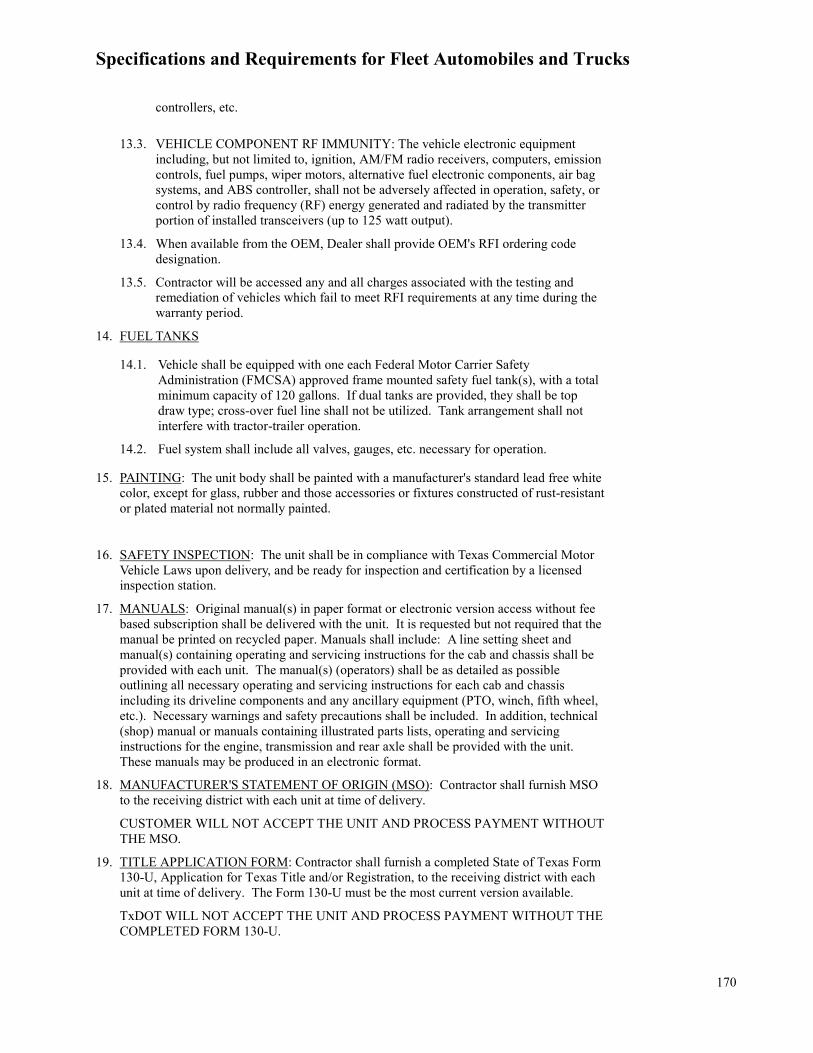
Specifications and Requirements for Fleet Automobiles and Trucks
170
controllers, etc.
13.3. VEHICLE COMPONENT RF IMMUNITY: The vehicle electronic equipment including, but not limited to, ignition, AM/FM radio receivers, computers, emission controls, fuel pumps, wiper motors, alternative fuel electronic components, air bag systems, and ABS controller, shall not be adversely affected in operation, safety, or control by radio frequency (RF) energy generated and radiated by the transmitter portion of installed transceivers (up to 125 watt output).
13.4. When available from the OEM, Dealer shall provide OEM's RFI ordering code designation.
13.5. Contractor will be accessed any and all charges associated with the testing and remediation of vehicles which fail to meet RFI requirements at any time during the warranty period.
14. FUEL TANKS
14.1. Vehicle shall be equipped with one each Federal Motor Carrier SafetyAdministration (FMCSA) approved frame mounted safety fuel tank(s), with a total minimum capacity of 120 gallons. If dual tanks are provided, they shall be top draw type; cross-over fuel line shall not be utilized. Tank arrangement shall not interfere with tractor-trailer operation.
14.2. Fuel system shall include all valves, gauges, etc. necessary for operation.
15. PAINTING: The unit body shall be painted with a manufacturer's standard lead free whitecolor, except for glass, rubber and those accessories or fixtures constructed of rust-resistantor plated material not normally painted.
16. SAFETY INSPECTION: The unit shall be in compliance with Texas Commercial MotorVehicle Laws upon delivery, and be ready for inspection and certification by a licensedinspection station.
17. MANUALS: Original manual(s) in paper format or electronic version access without feebased subscription shall be delivered with the unit. It is requested but not required that themanual be printed on recycled paper. Manuals shall include: A line setting sheet andmanual(s) containing operating and servicing instructions for the cab and chassis shall beprovided with each unit. The manual(s) (operators) shall be as detailed as possibleoutlining all necessary operating and servicing instructions for each cab and chassisincluding its driveline components and any ancillary equipment (PTO, winch, fifth wheel,etc.). Necessary warnings and safety precautions shall be included. In addition, technical(shop) manual or manuals containing illustrated parts lists, operating and servicinginstructions for the engine, transmission and rear axle shall be provided with the unit.These manuals may be produced in an electronic format.
18. MANUFACTURER'S STATEMENT OF ORIGIN (MSO): Contractor shall furnish MSOto the receiving district with each unit at time of delivery.
CUSTOMER WILL NOT ACCEPT THE UNIT AND PROCESS PAYMENT WITHOUT THE MSO.
19. TITLE APPLICATION FORM: Contractor shall furnish a completed State of Texas Form130-U, Application for Texas Title and/or Registration, to the receiving district with eachunit at time of delivery. The Form 130-U must be the most current version available.
TxDOT WILL NOT ACCEPT THE UNIT AND PROCESS PAYMENT WITHOUT THE COMPLETED FORM 130-U.

Specifications and Requirements for Fleet Automobiles and Trucks
171
OPTIONAL EQUIPMENT
Optional equipment must be identified on the PO to be required.
NOTE: Welding to the truck frame is not acceptable. Hole drilling shall be confined to the vertical face of the truck frame.
1. OPTION NO. 1: POWER TAKE-OFF (PTO), HYDRAULIC WINCH, STEEL HEADACHE RACK, and TOOL BOXES. Shall include the following:
1.1. Power take-off shall be a transmission mounted power take-off (PTO) capable of accepting a hydraulic pump required to drive a rear-mounted winch and trailer hydraulics and shall:.
1.1.1. Be equipped with an automatic Kick-Out control with low truck speed limitation which shall disengage the PTO at 10 MPH.
1.1.2. Be equipped with air type controls to operate the PTO, pump, and winch.
1.1.3. Include valving, controls and a three line system (two coupler) consisting of a pressure line, return line and by-pass line to protect hydraulic system.
1.1.4. Include a dash mounted indicator light shall be installed in the cab to indicate:
1.1.4.1. PTO (On or Off)
1.1.4.2. Pump (Engaged-Disengaged)
1.1.4.3. Winch (Engaged-Disengaged)
1.2. Hydraulic pump shall be capable of 15 to 25 gpm via a flow control valve and providing a minimum 2400 psi hydraulic pressure.
1.3. WINCH shall be a heavy-duty hydraulic PTO driven winch shall be installed immediately behind the truck cab and shall:
1.3.1. Be rated at 65,000 lbs. capacity
1.3.2. Provide a minimum of two speeds forward and one reverse.
1.3.3. Be equipped with jaw clutch, drum brake, and automatic worm or planetary brake.
1.3.4. Be equipped with a minimum 7/8 inch thick aircraft type cable, minimum 150 foot in length including tail chain and hook.
1.3.5. Winch mounting brackets shall be constructed of minimum 1/2 inch steel plate.
1.4. STEEL HEADACHE RACK shall be Heavy-duty, constructed of a minimum 2-1/2 inch and 3 inch heavy-duty pipe or minimum 3” x 3” square tubing, minimum .25” wall, constructed to industry standards and capable of handling the mounting and load stress caused by the operation of the attached winch. All electrical wiring shall be enclosed in conduit.
1.4.1. Height of headache rack shall be level with the height of the chassis cab.
1.4.2. Headache rack shall have mounting brackets and conduit so that a light bar can be added by TxDOT personnel.
1.4.3. Headache rack shall have a top mount light bar pad measuring approximately 51” wide so that a light bar can be added by TxDOT personnel.
1.4.4. Two LED type brake, turn signal and reverse lights shall be mounted on the top of the headache rack.
1.4.5. Two LED type work lights shall be mounted on the headache rack facing rearward and wired to a switch mounted in the cab.
1.4.6. Two open top storage boxes made of angle iron and expanded metal shall be mounted on rear of headache rack for storage of chains and ratchets.
1.4.7. Three weather proof, oilfield type tool boxes shall be provided, one mounted on each side and one

Specifications and Requirements for Fleet Automobiles and Trucks
172
mounted on rear.
1.4.7.1. Toolboxes shall be constructed of minimum 14 gauge steel.
1.4.7.2. Dimensions shall be (nominal) 18 x 18 x 24 inches.
1.5. ROLLING TAILPIPE as described in OPTION NO. 3 below.
2. OPTION NO. 2: ALUMINUM HEADACHE RACK – The unit shall meet the following requirements:
2.1. Aluminum headache rack shall measure approximately 68” x 76” with radius top corners.
2.2. Height of headache rack shall be level with the height of the chassis cab.
2.3. Headache rack shall have a top mount light bar pad measuring approximately 51” wide so that a light bar can be added by TxDOT personnel.
2.4. Headache rack shall have a jail bar window measuring approximately 22”W x 25”H.
2.5. Three weather proof compartments shall be provided, all mounted on rear. Compartments shall be constructed of aluminum and have two shelves in each compartment. Compartments shall be a minimum 11” deep.
2.6. Headache rack shall me mounted using fasteners approved by manufacturer of headache rack.
EXAMPLE: Merritt Dyna-Light 318 or equal.
NOTE: ALUMINUM HEADACHE RACKS CANNOT BE ORDERED WITH OPTION #1.
3. OPTION NO. 3: ROLLING TAIL PIPE – A tailboard roller shall be installed on the end of the truck frame and shall be approximately 36” wide. The roller shall be constructed of double extra-heavy-duty pipe minimum 6-5/8 inches outside diameter (OD) with ends mounted on heavy-duty bearings. A steel shaft shall run through the roller and connect on each rail of the truck frame. Angled loading skids shall be installed between the front of the roller and the fifth wheel to enable the kingpin of a trailer to clear the roller when being loaded. The roller assembly shall be attached to the end frame with bolts; a welding method is not acceptable.
4. OPTION NO. 4: FIFTH WHEEL – Cast steel, 36 inches. Fifth wheel shall be mounted 4 inches forward of the center of the tandem. Safety latch location is at Contractor's option, mounted on street side of unit.
4.1. Stationary fifth wheel, mounted between 51 and 59 inches from ground, unless otherwise specified.
4.2. Air sliding type fifth wheel, complete with in cab controls. Mounted so forward-most position of king pin is 15 inches forward of the center line of the tandem. Slide rack travel length shall be minimum 36 inches. Shall be mounted between 53 and 57 inches from ground, unless otherwise specified.
5. OPTION NO. 5: QUARTER FENDERS AND MUD FLAPS – Rear quarter fenders, mounted forward of the front drive axle, with anti-sail and anti-spray mud flaps spring mounted with Betts brackets (or equal) mounted rear of the rear drive axle. Mud flaps shall reach to within 8 inches of the ground. NOTE: Advertisements are not permitted on mud flaps.
6. OPTION NO. 6: FIFTH WHEEL OILFIELD BODY – Shall meet the following requirements:
6.1. Constructed of horizontal steel channel long sills and cross-members, sized and spaced for proper tire clearance and load capacity for the specified truck. Body length shall be configured to fit the chassis and wheelbase specified. Width shall be (nominal) 96 inches.
6.2. Floor shall be a continuous bed constructed with minimum 3/16 inch safety tread plate steel. Floor shall be sufficiently braced to prevent distortion under load. Flat folding three rung step ladders shall be provided on both curbside and streetside of body along with a folding grab handle. Ladder and grab handle shall be capable of folding flat on deck floor for storage or when not in use.
6.3. Unit shall be equipped with a fifth wheel, meeting the requirements of Option No. 4.1 or 4.2., which shall be bolted through the body to the chassis frame in accordance with manufacturer's fifth wheel mounting recommendations (welding the chassis frame is prohibited).

Specifications and Requirements for Fleet Automobiles and Trucks
173
6.4. The body and toolboxes shall be painted with a manufacturer's standard lead free black color, except for glass, rubber and those accessories or fixtures constructed of rust-resistant or plated material not normally painted. Surface preparation: All surfaces, including cross members and long sills, shall be thoroughly cleaned to remove all dirt, oil, grease, rust, slag, scale, and other foreign matter prior to priming. All welds shall be ground to a smooth finish. The cleaned and prepared surfaces shall be given a shop coat of primer and then thoroughly dried. The primer used shall be compatible with the finish coat in order to ensure proper adhesion of the finish coat. The finish coat shall be first quality air drying paint. The minimum dry film thickness of the finish coat shall be four mil.
7. OPTION NO. 7: GIN POLES: Two gin poles shall be provided, constructed of minimum 4-1/2 inch OD schedule 80 seamless pipe. Dimensions to be 9 feet 5 inches long (length may be reduced, to prevent interference with cab doors). Troughs shall fit within the 96” maximum body width. Shall include an "A" frame, with snatch block, folding toggle bar, and guy chains. Folding toggle block shall be positioned behind the gin pole pivot point. Gin poles shall be mounted ahead of the rolling tailpipe in a manner that will permit them to be folded forward or removed. Troughs shall be located at the outer edge of the body, for storage of the gin poles.
8. OPTION NO. 8: BACK-UP CAMERA SYSTEM: Headache rack mounted rear facing camera wired to in-cab monitor. Camera shall be able to operate automatically when in reverse and operator shall have the option to operate in forward gear. Make and Model used shall be: Zone Defense ZD.323.1CH or equal. Placement of camera and monitor shall be approved by TxDOT Fleet Acquisitions personnel prior to delivery.
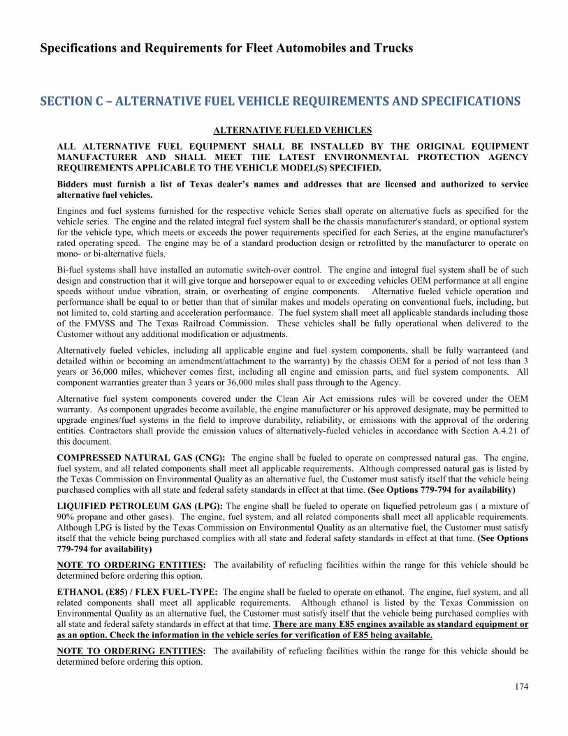
Specifications and Requirements for Fleet Automobiles and Trucks
174
SECTION C – ALTERNATIVE FUEL VEHICLE REQUIREMENTS AND SPECIFICATIONS
ALTERNATIVE FUELED VEHICLES
ALL ALTERNATIVE FUEL EQUIPMENT SHALL BE INSTALLED BY THE ORIGINAL EQUIPMENT MANUFACTURER AND SHALL MEET THE LATEST ENVIRONMENTAL PROTECTION AGENCY REQUIREMENTS APPLICABLE TO THE VEHICLE MODEL(S) SPECIFIED.
Bidders must furnish a list of Texas dealer’s names and addresses that are licensed and authorized to service alternative fuel vehicles.
Engines and fuel systems furnished for the respective vehicle Series shall operate on alternative fuels as specified for the vehicle series. The engine and the related integral fuel system shall be the chassis manufacturer's standard, or optional system for the vehicle type, which meets or exceeds the power requirements specified for each Series, at the engine manufacturer's rated operating speed. The engine may be of a standard production design or retrofitted by the manufacturer to operate on mono- or bi-alternative fuels.
Bi-fuel systems shall have installed an automatic switch-over control. The engine and integral fuel system shall be of such design and construction that it will give torque and horsepower equal to or exceeding vehicles OEM performance at all engine speeds without undue vibration, strain, or overheating of engine components. Alternative fueled vehicle operation and performance shall be equal to or better than that of similar makes and models operating on conventional fuels, including, but not limited to, cold starting and acceleration performance. The fuel system shall meet all applicable standards including those of the FMVSS and The Texas Railroad Commission. These vehicles shall be fully operational when delivered to the Customer without any additional modification or adjustments.
Alternatively fueled vehicles, including all applicable engine and fuel system components, shall be fully warranteed (and detailed within or becoming an amendment/attachment to the warranty) by the chassis OEM for a period of not less than 3 years or 36,000 miles, whichever comes first, including all engine and emission parts, and fuel system components. All component warranties greater than 3 years or 36,000 miles shall pass through to the Agency.
Alternative fuel system components covered under the Clean Air Act emissions rules will be covered under the OEM warranty. As component upgrades become available, the engine manufacturer or his approved designate, may be permitted to upgrade engines/fuel systems in the field to improve durability, reliability, or emissions with the approval of the ordering entities. Contractors shall provide the emission values of alternatively-fueled vehicles in accordance with Section A.4.21 of this document.
COMPRESSED NATURAL GAS (CNG): The engine shall be fueled to operate on compressed natural gas. The engine, fuel system, and all related components shall meet all applicable requirements. Although compressed natural gas is listed by the Texas Commission on Environmental Quality as an alternative fuel, the Customer must satisfy itself that the vehicle being purchased complies with all state and federal safety standards in effect at that time. (See Options 779-794 for availability)
LIQUIFIED PETROLEUM GAS (LPG): The engine shall be fueled to operate on liquefied petroleum gas ( a mixture of 90% propane and other gases). The engine, fuel system, and all related components shall meet all applicable requirements. Although LPG is listed by the Texas Commission on Environmental Quality as an alternative fuel, the Customer must satisfy itself that the vehicle being purchased complies with all state and federal safety standards in effect at that time. (See Options 779-794 for availability)
NOTE TO ORDERING ENTITIES: The availability of refueling facilities within the range for this vehicle should be determined before ordering this option.
ETHANOL (E85) / FLEX FUEL-TYPE: The engine shall be fueled to operate on ethanol. The engine, fuel system, and all related components shall meet all applicable requirements. Although ethanol is listed by the Texas Commission on Environmental Quality as an alternative fuel, the Customer must satisfy itself that the vehicle being purchased complies with all state and federal safety standards in effect at that time. There are many E85 engines available as standard equipment or as an option. Check the information in the vehicle series for verification of E85 being available.
NOTE TO ORDERING ENTITIES: The availability of refueling facilities within the range for this vehicle should be determined before ordering this option.

Specifications and Requirements for Fleet Automobiles and Trucks
175
HYBRID: The engine shall be fueled to operate on Hybrid, gas/electric. The engine, fuel system, and all related components shall meet all applicable requirements. Although electricity is listed by the Texas Commission on Environmental Quality as an alternative fuel, the Customer must satisfy itself that the vehicle being purchased complies with all state and federal safety standards in effect at that time. . OEM/Contractor of Hybrid vehicles shall provide estimated ranges for electricity use and conventional fuel use as a percentage of total drive time (i.e. 25% electricity, 75% gas) and expected variations between highway and city use.
PLUG-IN HYBRID ELECTRIC (PHEV): In addition to Hybrid requirements, OEM/Contractor shall provide details regarding driving range, recharge time, battery life and replacement costs, and vehicle weight.
ELECTRIC VEHICLES: OEM/Contractor shall provide details regarding driving range, recharge time, battery life and replacement costs, and vehicle weight.
NOTE: In addition to the vehicles listed in this section; additional vehicle models may modified to accommodate alternative fuels. Please see the “Options” section of theses specifications for availability. For example, options 779-794 detail which vehicles have LPG/CNG engine options.
Note: On specification tables, rim size means tire width, unless otherwise indicated.

Specifications and Requirements for Fleet Automobiles and Trucks
176
ALTERNATIVE FUELED VEHICLES
Unless specified, all units shall be furnished complete with standard equipment and factory-installed accessories as listed in the manufacturer's printed literature for the models specified herein). The Alternative Fueled Automobiles are required to have the same equipment as all automobiles.
SERIES 341ALT HYBRID GAS/ELECTRIC COMPACT SEDAN
4-CYLINDER, 4-DOOR FRONT WHEEL DRIVE
ITEM Minimum Toyota Prius Honda Civic Ford C-Max Chevrolet Volt
Body Trim Designation (Base Vehicle)
As shown 1223 Hybrid Hybrid 1RF68 Hybrid
Wheelbase, inches 104.3 106.3 106.3 104.3 106.1 Length, inches 173.6 175.6 176.7 173.6 180.4 Width, inches 68.7 68.7 69 72 71.2 Displacement, liters As shown 1.8L 4 cyl 1339 cc 2.0L I4 1.5L 4 cyl.
Engine Gross HP (CVT) @rpm (SAE net/with IMA)
As shown 98@5200/
134 IMA Net HP
110@6000 141@6000/ 188 Net HP
83@4,900/ 149 Net HP
Tire Size & Load Range As shown P195/65R15 P195/65R15
89S P225/50R17 P215/50R17
Emissions Certification As shown
AT-PZEV (Emissions
SULEV) Bin 3 ULEV TBD Bin 4 ULEV2
SERIES 342ALT ALL ELECTRIC VEHICLE
4-DOOR SEDAN

Specifications and Requirements for Fleet Automobiles and Trucks
177
FRONT WHEEL DRIVE
ITEM Minimum Requirements
Miles (Low Speed)
Nissan Leaf (Highway
Speed)
Ford Focus Electric
Chevrolet Bolt
Body Trim Designation (Base Vehicle) As shown ZX40S S S 1FB48
LT Wheelbase, inches 93.5 94 106.3 104.3 102.4 Length, inches 134 134 175 172.9 164.0 Width, inches 58 58 69.7 71.8 69.5
GVWR (approx.) As Shown 2350 4409 3563
Passengers As shown 4 5 5 5
Electric motor As shown
72V Brushless 3 Phase
Induction AC Motor
Lithium Ion Manganese
Permanent magnet electric traction, lithium-ion (23-kWh capacity)
Permanent magnetic drive
motor
Engine Gross HP Rated/Peak Power As shown 10 hp/35 hp 107 143 200
Range As shown 35-45 miles 100 miles* 115 238
Top Speed (MPH) As shown 25 90 84 91 Tire Size & Load Range /two-ply street rated tires
As shown 13 inch P205/55R16 P225/50/R17 P215/50R17
Emissions Certification As shown ZEV ZEV ZEV ZEV
SERIES 343ALT PLUG-IN HYBRID GAS/ELECTRIC COMPACT SEDAN
4-CYLINDER, 4-DOOR FRONT WHEEL DRIVE
ITEM Minimum Toyota Prius Prime Honda Civic Ford C-Max
Energi Chevrolet
Volt Body Trim Designation (Base Vehicle) As shown PLUS Hybrid SE 1RF68
Hybrid Wheelbase, inches 104.3 106.3 106.3 104.3 106.1 Length, inches 173.6 175.6 176.7 173.6 180.4 Width, inches 68.7 68.7 69 72 71.2 Displacement, liters As shown 1.8L 4 cyl 1339 cc 2.0L I4 1.5L 4 cyl. Engine Gross HP (ECVT) @rpm (SAE net/with IMA)
As shown 95@5200/ 121 Net HP 110@6000 141@6000/
188 Net HP 83@4,900/ 149 Net HP
Tire Size & Load Range As shown P195/65R15 P195/65R15 89S P225/50R17 P215/50R17
Emissions Certification As shown SULEV/TZEV ULEV TBD Bin 4 ULEV2
SERIES 359ALT HYBRID GAS/ELECTRIC INTERMEDIATE SEDAN

Specifications and Requirements for Fleet Automobiles and Trucks
178
4-CYLINDER, 4-DOOR FRONT WHEEL DRIVE
ITEM Minimum Requirements Camry Hybrid Ford Fusion Chevrolet
Malibu Body Trim
Designation (Base Vehicle)
As shown 2559 Hybrid 1ZE69 w/1HY
Wheelbase, inches 107.8 109.3 112.2 111.4 Length, inches 189.2 189.2 191.8 193.8 Width, inches 71.7 71.7 72.9 73.0
Displacement, liters As shown 2.4L 4 Cyl 2.0L I4 1.8L 4 cyl Engine Gross HP
(CVT) @rpm (SAE net/with IMA)
As shown 147@6000 187 IMA net HP
141@6000 (188 net HP when combined with
electric motor)
124@5,000
Tire Size & Load Range As shown P215/60R16 P215/60H16 P225/55R17
Emissions Certification As shown AT-PZEV Bin 3 Tier 2 Bin 3 ULEV II BIN5/ULEV125
SERIES 360ALT PLUG-IN HYBRID GAS/ELECTRIC INTERMEDIATE SEDAN
4-CYLINDER, 4-DOOR FRONT WHEEL DRIVE
ITEM Minimum Requirements Camry Hybrid Ford Fusion Energi
Body Trim Designation (Base
Vehicle) As shown 2559 P0P800A
Wheelbase, inches 107.8 109.3 112.2 Length, inches 189.2 189.2 191.8 Width, inches 71.7 71.7 72.9
Displacement, liters As shown 2.4L 4 Cyl 2.0L I4 Engine Gross HP
(CVT) @rpm (SAE net/with IMA)
As shown 147@6000 187 IMA net HP
141@6000 (188 net HP when combined with
electric motor) Tire Size & Load
Range As shown P215/60R16 P225/50R17
Emissions Certification As shown AT-PZEV Bin 3 Tier 2 Bin 3 ULEV II

Specifications and Requirements for Fleet Automobiles and Trucks
179
ALTERNATIVE FUEL – UTILITY VEHICLE SERIES 640ALT
HYBRID GAS/ELECTRIC UTILITY 4-DOOR, FRONT WHEEL DRIVE
ITEM Minimum Requirements
Toyota Highlander
Body Trim Designation (Base Vehicle) As Shown 6964
HYBRID
Wheelbase, inches 109.8 109.8 Length, inches 188.2 188.2 Width, inches 75.2 75.2 Displacement, liters As shown 3.5L V6 Engine Gross HP As shown 280 Net Torque As shown 212
Tire Size & Load Range As shown P245/65R17
Emissions Certification As shown SULEV/ TIER2BIN3
ALTERNATIVE FUEL – PICKUP TRUCK
SERIES 862ALT HYBRID GAS/ELECTRIC
FULL SIZE, ½ TON, CREW CAB 2-Wheel Drive
ITEM Minimum Requirements
Chevrolet Silverado 1500*
Body Trim Designation (Base Vehicle) As Shown 1LT
(PDE) Wheelbase, inches 143.5 143.5 Approximate Payload Allowance, pounds 1759 1,870
Length, inches 229.9 230.0 Width, inches 78 78.9 GVWR, pounds 6,800 7,000
Displacement, liters As shown 5.3L V-8 E-85
Engine Gross HP As shown 285 Net Torque As shown 305
Transmission, Automatic As shown 8 speed
Rim size, inches As shown 17X8 Tire Size & Load Range As shown 255/70R15 Emissions Certification As shown TBD

Specifications and Requirements for Fleet Automobiles and Trucks
180
SECTION D – OPTIONAL EQUIPMENT SPECIFICATIONS
NOTE TO ORDERING ENTITIES:
1) OPTIONS WHICH ARE NOT AVAILABLE IN TXSMARTBUY, MUST BE PROCURED BY THE CUSTOMER AND A SEPARATE PURCHASE ORDER ISSUED TO THE CONTRACTOR.
The following optional equipment shall be furnished when so specified in the PO:
OPTION NO. OPTION DESCRIPTION
4 AXLE RATIO: Rear axle ratio shall be specified by the Customer in accordance with manufacturer availability. (Customer to specify the ratio).
6 ALL WHEEL DRIVE (Any series where this upgrade is available) 7 EXTRA KEYS-At Time Of Delivery, Each Vehicle Will Have Three (3) Ignition/Door (In addition to minimum
provided by manufacturer). 13 FLASHER SYSTEM- Headlamp And Tail Lamp. Separates the headlamp and tail lamp flashing 15 ALTERNATOR (for light-duty trucks and pickups only): Manufacturer's higher capacity alternator. Customer to
specify the minimum amperage required on the purchase order. 16 ALTERNATOR (primarily for medium-duty trucks): Manufacturer's heavy-duty high capacity alternator.
Customer to specify the minimum amperage required on the purchase order. 19 AXLE, FRONT: (Series 985 through 990). Minimum 12,000 pound capacity front GAWR. 20 AXLE, REAR, TWO-SPEED (for Series 950 through 985 trucks only): Shall be furnished with a manual
transmission. Transmission and rear axle combination shall provide the following performance: grade ability minimum 1.1 percent at 55 MPH; maximum road speed 70 MPH; cruise control set at 60 MPH. Not recommended (and limited availability) for vehicles with automatic transmission.
23 ANTITHEFT DEVICE Contractor Must Furnish All Parts And Labor To Install The Antitheft Device According To Manufacturer And Customer Instructions. Referenced Brand/Model: Tremco Antitheft System (CHGR12=INT-RI), or DPS approved Brand
24 BRAKES, AIR (ABS) FOR TRACTOR APPLICATION WITH GLAD-HANDS (Complete Package for use with diesel or gasoline engines - for Series 970 through 980 trucks, but may be used on other size trucks based on availability with gasoline engines): An under-hood air-compressor shall be installed to power the air brake system.
25 BRAKES, AIR (ABS) FOR TRACTOR APPLICATION WITH GLAD-HANDS (Complete Package for use with diesel- for Series 970 through 1200 series trucks, but may be used on other size trucks based on availability): An under-hood air-compressor shall be installed to power the air brake system.

Specifications and Requirements for Fleet Automobiles and Trucks
181
30 BED LINER, SPRAY-ON: Shall be elastomeric polyurethane. Bed liner shall be 100% solids (no VOC’s, no solvents). Shall be applied at a thickness no less than 1/8” on walls and no less than 1/4" on floor and tailgate. Application will not inhibit access and use of factory tie downs. Durable, impact absorbing, abrasion resistant and skid resistant. Shall also be weather and corrosion resistant and shall not become brittle due to sun, rain, ice, or other environmental factors, at ambient temperatures of –20 degrees to 110 degrees Fahrenheit. Shall resist damage from grease, oil, gasoline and other chemicals. Shall be covered by limited lifetime warranty. Referenced Brand: Rhino Linings, TUFF STUFF© - man, or equal
33 CAB-TO-AXLE (C-A:102-108 inch effective), INCREASED/LONGER, for medium-duty and heavy duty trucks): Cab-to-Axle (C-A) will be 102 -108 inches.
34 CAB-TO-AXLE (C-A:120 inch effective) INCREASED/LONGER, (for medium-duty and heavy duty trucks): Cab-to-Axle (C-A) will be 120 inches.
35 CAB-TO-AXLE (C-A: 136-139 inches effective), INCREASED/LONGER, (for medium-duty and heavy duty trucks): Cab-to-Axle (C-A) will be 121-186 inches.
36 BATTERIES-Dual Cranking 730 CCA MIN 37 COLORS: Manufacturer's Standard Colors - shall be as specified by the Customer from manufacturer’s standard
colors available. (ex: Red, Black, White, Silver, Gold, Navy). More colors may be added per agency's request. 38 (DELETE) DAYLIGHT RUNNING LIGHTS : Option to delete the daytime running lights 45 DIFFERENTIAL, MAXIMUM TRACTION, LIMITED SLIP TYPE: The maximum traction type differential
shall be Posi-traction, no-spin, or equal (N/A on front wheel drive vehicles or medium duty trucks)
48 ENGINE, HIGHER PERFORMANCE (HORSEPOWER/DISPLACEMENT) WHERE AVAILABLE: Provide the next higher Horsepower ILO and/or larger displacement over what is listed as the base vehicle in the table for the appropriate series.
52 FOUR-WHEEL DRIVE: Four-wheel drive vehicles shall include automatic locking hubs and skid plates.
57 FUEL TANK, STEP TYPE: (65 GALLONS) FUEL TANK(S), AUXILIARY, CONVENTIONAL FUEL, DOT (FHA) - for Series 930 through 990 trucks only (See Options 57 and 58): Auxiliary fuel tank(s) shall be furnished in addition to the standard fuel tank(s) and shall be complete with in-cab fuel gauges. Tank(s) shall be securely mounted to the frame and shall not interfere with dump operation (where applicable) - See external running board requirements in Section C.8.b.8. NOTE: SHOP-BUILT TANKS ARE UNACCEPTABLE; ALL FUEL TANKS SHALL BE CHASSIS-FACTORY INSTALLED.
58 FUEL TANK, DUAL STEP TYPE: (70 GALLONS) FUEL TANK(S), AUXILIARY, CONVENTIONAL FUEL, DOT (FHA) - for Series 930 through 990 trucks only (See Options 57 and 58): Auxiliary fuel tank(s) shall be furnished in addition to the standard fuel tank(s) and shall be complete with in-cab fuel gauges. Tank(s) shall be securely mounted to the frame and shall not interfere with dump operation (where applicable) - See external running board requirements in Section C.8.b.8. NOTE: SHOP-BUILT TANKS ARE UNACCEPTABLE; ALL FUEL TANKS SHALL BE CHASSIS-FACTORY INSTALLED.
59 FUEL TANKS, INCREASED CAPACITY: The manufacturer shall furnish the largest fuel capacity available for the model offered. The fuel tank(s) furnished must meet or exceed requirements set forth in FMVSS No. 302-75. NOTE: Optional, increased capacity fuel tank(s) are not available on passenger cars and station wagons. They are also not available on certain models of light duty trucks and vans. Ordering this option will provide the largest capacity available (if any) furnished by the manufacturer.
63 GRILLE GUARD, HEAVY-DUTY, ROUND TUBE: A heavy-duty grille guard to protect headlamps and grille of a vehicle. This guard shall include: (1) Push Bar Pads (2) Made from 14 gauge (min) steel tubing (3) Bolted to the frame (Thread-forming bolts or screws are not acceptable) (4) Pre-treated for rust prevention prior to application of powder coated final finish.(Color specified by the Customer). (Ref: Section A.4.8 – General Requirements and Information).
66 HEADLINER, FULL LENGTH: For cargo vans, factory installed required where available 67 SEATS - ALL SEATS TO BE CLOTH, 40/20/40 FRONT SPLIT 68 SEATS - DRIVER'S SEAT TO BE POWER ADJUSTABLE

Specifications and Requirements for Fleet Automobiles and Trucks
182
69 LIGHTING - LAMP INOPERATIVE DOME, 70 FLOOR MATS, FRONT AND REAR, (Only available in vehicles with carpeted floors) 73 LIGHTING-LIGHT BAR- LAW ENFORCEMENT- Pursuit police vehicle LED overhead light bar. The light bar
shall contain: four corner linear LED lamps; Two front-facing directional linear lamps consisting of one red and one blue; Four rear-facing duplex linear lamps consisting of two red and two blue positioned over a six lamp linear LED traffic advisor; Six halogen lamps consisting of left and right alley lights, two takedown lights and two flashing and/or constant-on take down lights. Example: Whelen FL8TX2 or equal. Agency must specify 49 ¾ inch or 55 inch length light bar.
74 MIRRORS, REARVIEW, EXTERIOR, LOW MOUNT, TRAILER TOW/CAMPER TYPE, LEFT AND RIGHT SIDES (where available): Manufacturer's low mount (below eye level) wide view-type mirror, which shall meet or exceed the requirements of FMVSS No. 111 and shall have a face size approximately 6 inch by 9 inch. Extension arms are required on chassis-cab unit.
75 MIRRORS, REARVIEW, EXTERIOR, POWER, LOW MOUNT TYPE, LEFT AND RIGHT SIDES (where available). Manufacturer's low mount (below eye level) wide view-type mirror, which shall meet or exceed the requirements of FMVSS No. 111 and shall have a face size approximately 6 inch by 9 inch. Extension arms are required on chassis-cab unit
77 MIRRORS HEATED, REARVIEW, EXTERIOR: Power, Body Color (if available). 78 TRUNK RELEASE TO BE IGNITION FED 81 POWER TAKE-OFF (PTO), Hydraulic (when available), SINGLE SPEED, ONE GEAR (NO REVERSE): PTO
shall have a shaft output speed (RPM) of minimum 50 percent and a maximum of 80 percent of engine speed (RPM) for truck dump body operation. The output shaft shall have an RPM speed of approximately 90 percent on diesel engines. The PTO shall be furnished complete with cab controls (including a dash-mounted light to indicate when PTO is in operation) and shift linkage. The cut-out for the cab controls shall be held to the absolute minimum necessary for installation and operation and shall be sealed watertight. All PTO assemblies shall be repairable type with replaceable bearings, seals, gaskets, and other parts
83 POWER TAKE-OFF (PTO), SINGLE SPEED, HYDRAULIC (when available), TWO GEAR (ONE FORWARD AND ONE REVERSE): PTO shall have a shaft output speed (RPM) of minimum 50 percent a maximum of 80 percent of engine speed (RPM) for truck operation. The output shaft shall have an RPM speed of approximately 90 percent of diesel engines. The PTO shall be furnished complete with cab controls (including a dash-mounted light to indicate when PTO is in operation) and shift linkage. The cut out for the cab controls shall be held to the absolute minimum necessary for installation and operation and shall be sealed watertight. All PTO assemblies shall be repairable type with replaceable bearings, seals, gaskets, and other parts
88 HEADACHE RACK STEEL, (for light-duty pickup trucks only): A light-duty headache rack shall be provided to protect the rear window. It shall be constructed of a frame of minimum 1/2 inch by 3 inch steel flat bar, and a window covering of 16-gauge horizontal louvers, evenly spaced at approximately 2 inch intervals, adequately braced with gussets to insure stability and strength. The mounting shall be accomplished by the use of the most appropriate size bolts with nuts and flat washers to insure safe and secure mounting. It shall be mounted to facilitate cleaning of the rear window, and so designed to provide an unobstructed visibility of the center-mounted, rear window of cab-mounted stop
89 HEADACHE RACK, NO LOUVER WINDOW GRILL (for light-duty pickup trucks only): End plates are to be constructed at a minimum of ½” x 3” cold rolled steel flatbar. Upper and lower crossbars are to a minimum of 2” x 2” square tubing with minimum .065 wall. Mounting brackets are constructed of a minimum of 3/16” steel. A light-duty headache rack shall be provided to protect the rear window. The mounting shall be accomplished by the use of the most appropriate size bolts with nuts and flat washers to insure safe and secure mounting. Headache rack shall be treated in a chemical bath or dip, or similarly treated for rust prevention prior to application of the final finish.
93 RADIO FREQUENCY INTERFERENCE (RFI): This option will be required on all vehicles by MY2012
Radio frequency (RFI) interference suppression shall be incorporated so as to provide RF interference immunity to and from land mobile radio transceivers operating in the following bands: Low band (30 to 50 MHZ), high band (140 to 174 MHZ), UHF band (440 to 512 MHZ) and the 700/800/900 MHZ band (700 to 975 MHZ).

Specifications and Requirements for Fleet Automobiles and Trucks
183
Typical land mobile radio transceivers will utilize a 3dB gain roof mount antenna with up to a 125 watt RF power output. Antennas will be mounted on the roof, front fender, and/or rear fender.
The RF immunity requirement shall apply to all Contractor supplied equipment and components thereof.
THESE VEHICLES WILL BE SUBJECT TO TESTING UPON DELIVERY IN ACCORDANCE WITH THE TESTS DEFINED BELOW. Dealers must provide OEM's RFI ordering code designation.
RADIO TRANSCEIVER IMMUNITY: The vehicle electronic equipment shall not be adversely affected in operation, safety, or control by radio frequency (RF) energy. For Land Mobile Radio Transceiver Interference: All vehicle electronic circuits including, but not limited to, ignition, AM/FM radio receivers, computers, emission controls, fuel pumps, wiper motors, alternative fuel electronic components, air bag systems, and ABS controller, shall be designed to suppress, bypass, or otherwise prevent interference from affecting the radio transceiver. In accordance with the tests defined below, Contractor will be accessed any and all charges associated with the testing of vehicles, which fail to meet RFI requirements. TEST METHOD/TEST LIMIT: Texas Department of Transportation (TxDOT) Radio Frequency (RF) Radio Interference "SINAD" Test, Texas Test Method TEX 1160-U, Latest Revision.
VEHICLE: The vehicle electronic equipment including, but not limited to, ignition, AM/FM radio receivers, computers, emission controls, fuel pumps, wiper motors, alternative fuel electronic components, air bag systems, and ABS controller, shall not be adversely affected in operation, safety, or control by radio frequency (RF) energy generated and radiated by the transmitter portion of installed transceivers (up to 120 watt output). In accordance with the tests defined below, Contractor will be accessed any and all charges associated with the testing of vehicles which fail to meet RFI requirements. TEST METHOD/TEST LIMIT: Society of Automobile Engineers (SAE) Surface Vehicle Standard Vehicle Electromagnetic Immunity-On-Board Transmitter Simulation-J551/12, Latest Revision.
94 PACKAGE-CRUISE CONTROL AND TILT STEERING WHEEL PACKAGE: CHASSIS MANFACTURER’S STANDARD
95 SEATS, 40/60 or 40/20/40 SPLIT BENCH SEAT (for Series 930 through 1200). 96 SEATS, PASSENGER, HIGH-BACK AIR RIDE:(for Series 970 through 1200)–Same as driver's seat.
98 (DELETE)-REAR SEATS DELETE (for extended cab pickups only). * Note: May Not be available from certain manufacturers)
99 SEATS-REAR SEATS, THIRD ROW (for utility vehicles, where available): To increase seating capacity
100 (DELETE)-REAR SEATS DELETE OPTION: ( Series 760C full size extended passenger VAN 101 EXTRA REMOTE KEYLESS ENTRY DEVICES: With a minimum of 3 fobs/keyless entry devices furnished.
(In addition to standard number of devices provided by manufacturer) 102 LIGHTING-LIGHT BAR LED MULTI-DIRECTIONAL, AMBER– Full width LED Multi-directional, Amber
Light Bar shall be LED technology and consist of the following: One extruded aluminum I-beam light bar, eight 400 series Linear 8 LEDs and one pair 400 series halogen rear work lights. Light bar shall not include the wig-wag feature. Referenced brand:Whelen model FL8AAA (Whelen number or TxDOT – FLTXDOT1).
103 LIGHTING-LIGHT BAR LED MULTI-DIRECTIONAL AMBER/BLUE – full width LED multi-directional, Amber/Blue Light bar shall be LED technology and consist of the following: One extruded aluminum I- beam light bar, four amber 400 series Linear 8 LEDs and one pair 400 series halogen rear work lights. Light bar shall not include the wig-wag feature. Whelen model FL8AAA (TxDOT item #FLTXDOT1).
104 LIGHTING-LIGHT BAR LED LOW PROFILE, AMBER – width low profile LED multi-directional, Amber Light bar shall be LED technology and consist of the following: One extruded aluminum I – beam light bar, eight 400 series Linear 8 LEDs. Light bar shall not include the wig-wag feature. EXAMPLE: Whelen model FL8AAA (Whelen number for TxDOT - #FLTXDOT1).

Specifications and Requirements for Fleet Automobiles and Trucks
184
105 LIGHTING-LIGHT BAR LED LOW PROFILE AMBER/BLUE– full width low profile LED multi-directional, Amber/Blue Light bar shall be LED technology and consist of the following: One extruded aluminum I – beam light bar, four amber 400 series Linear 8 LEDs and four blue (to be located on the driver side when mounted) 400 series Linear 8 LEDs. Light bar shall not include the wig-wag feature. EXAMPLE: Whelen model FL8AAA (TxDOT item #SLTXDOT3).
106 LIGHTING-TRAFFIC ADVISOR– LED Multi-Directional AMBER Traffic Advisor shall be LED technology and consist of the following: eight amber TIER 6 LED lights. Referenced brand: Whelen #TAM85.
109 LIGHTING-SPOTLAMPS (Available for LE Series vehicles): - Left Hand, Independently Fused . Factory Installed
112 LIGHTING - SPOT LAMP (LED BULB) , PERMANENT MOUNT, DRIVER SIDE ONLY , must be factory installed
116 TIRES, ALL TERRAIN: To provide the vehicle with All Terrain Tires in the largest size for the application as available. (4 x 4 only)
117 TOOL BOX, SINGLE LID, HEAVY-DUTY. ALUMINUM, SMOOTH OR DIAMOND TREAD, STANDARD APPLICATION: Dimensions shall be approximately 60 inches long (overall length, approximately 72 inches) by 17.5 inches deep, 20.0 inches wide. (Series 800s). Example: Weather Guard Model No. R-127, Rawson-Koenig Model No. C63A or equal. Substitutes must be approved by the ordering agency.
118 TOOL BOX, DUAL LID, STEEL, CROSSOVER TYPE, STANDARD APPLICATION: 118. TOOL BOX, STEEL, CROSSOVER TYPE, STANDARD APPLICATION: Dimensions shall be approximately 60 inches long (overall length 70 inches) by 16-1/2 inches deep, 20 inches wide. Example: Rawson-Koenig Model No. ST-63, Weather Guard Model No. R-125, or equal. Substitutes must be approved by the ordering agency.
119 TOOL BOX, DUAL LID, STEEL, CROSSOVER TYPE, SPECIAL APPLICATION, DEEP: Used mainly by engineers and surveyors. Dimensions shall be approximately 60 inches long (overall length 70 inches) by 25-1/2 inches deep, 30 inches wide. NOTE: Will not fit short bed pickups. Example: Rawson-Koenig Model No. ST-63WD, Weather Guard Model No. R-115 with E Dimension of 18 inches, or equal. Substitutes must be approved by the ordering agency.
120 TOOL BOX, SINGLE LID, HEAVY-DUTY. ALUMINUM, SMOOTH OR DIAMOND TREAD, ALL PURPOSE CHEST TYPE, STANDARD APPLICATION: Dimensions shall be approximately 58 inches long (overall length 61 inches) by 19 inches deep, 23 inches wide. Example: Weather Guard Model No. 664, Rawson-Koenig Model No. M60FW-1NMA or equal. Substitutes must be approved by the ordering agency.
121 TOOL BOX, SINGLE LID, HEAVY-DUTY. ALUMINUM, SMOOTH OR DIAMOND TREAD,ALL PURPOSE CHEST TYPE, APPLICATION FULL SIZE WIDE BED TRUCKS: Dimensions shall be approximately 48 inches long (overall length 61 inches) by 19 inches deep, 23 inches wide. Example: Rawson-Koenig Model No. M60SB-1NMA or equal. Substitutes must be approved by the ordering agency.
122 TOOL BOX, SINDLE LID, HEAVY-DUTY, STEEL, SMOOTH, CHEST TYPE, STANDARD APPLICATION (Series 842 – 888): Dimensions shall be approximately 58 inches long (overall length, approximately 58 inches) by 17.5 inches deep, 20.0 inches wide. Mounted to the floor of the body. Example: Rawson-Koenig Model No. M58U-1NM or equal. Substitutes must be approved by the ordering agency.
123 TOOL BOX, DUAL LID, HEAVY-DUTY, STEEL, SMOOTH, CHEST TYPE, STANDARD APPLICATION (Series 842 – 888): Dimensions shall be approximately 60 inches long (overall length, approximately 58 inches) by 18.5 inches deep, 20.0 inches wide. Mounted to the floor of the body. Example: Rowson-Koenig Model No. M60-2NM or equal. Substitutes must be approved by the ordering agency.
124 TOW DEVICES: 2 front mounted tow hooks (loops are acceptable) or 1 front-mounted heavy-duty tow pin, with minimum horizontal pull capacity of 28,000 pounds shall be installed by the truck chassis manufacturer.

Specifications and Requirements for Fleet Automobiles and Trucks
185
125 TRAILER, IN-CAB ELECTRIC BRAKE CONTROLLER: Cab control unit shall be furnished and installed, for applying trailer brakes both simultaneously and independent of the brakes of the towing vehicle. Approved Brand – Cequent Towing. Factory installed, if available.
128 TRANSMISSION, MANUAL, 5-SPEED (Series 842 – 888): Manufacturer's standard for series specified.
129 TRANSMISSION, MANUAL, 6-SPEED: Manufacturer's standard for series specified. 130 TRANSMISSION, MANUAL, 7-SPEED (Series 970 – 1200): Manufacturer's standard for series specified.
131 TRAILER TOWING PACKAGE (available for LE vehicle, Special Service Package: HEAVY-DUTY TRAILER TOW PACKAGE: Class IV hitch receiver, 4- and 7- pin connectors, heavy-duty auxiliary transmission oil cooler and radiator, and electronic brake wiring kit.
133 PACKAGE-TRAILER TOWING PACKAGE (light and medium duty trucks, utility vehicles and vans).All items are to be heaviest available OEM equipment for and installed by manufacturer. Shall include, but not be limited to, the following: (1)Auto Transmission oil cooler (2) heavy-duty radiator (3) Trailer wiring harness: A 7-Pin, RV style, Flat (spade) electrical connector to connect trailer wiring circuitry to the vehicle wiring harness. Class III (frame mounted) ,Class IV (frame mounted) or Class V (frame mounted or may be after frame mounted) Receiver Hitch. EXAMPLE: Grote 82-1058 or Equal.
134 CLASS V RECEIVER HITCH and 7-Pin RV style, Flat (spade) electrical connector plug, (Example : Grote 82-1058 or Equal)
137 WHEELCHAIR LIFT: Conversion of a full size van, or para-transit van body equipped with a raised roof, wheelchair lift, provisions for stand-up entry and wheelchair passenger securement for one wheelchair position. Note; this option reduces ambulatory passenger capacity . Refer to Section I Special Equipment-Para-transit Vehicles
138 WHEELCHAIR LIFT: Conversion of a full size van, or a para-transit van body equipped with a raised roof, wheelchair lift, provisions for stand-up entry and wheelchair passenger securement for two-wheelchair positions. Note; This option reduces ambulatory passenger capacity. Refer to Section I Special Equipment-Para-transit Vehicles
140 WINDOW TINT (Limited Application on non-passenger vehicles): Maximum available tint- factory-installed. Tinting shall meet Texas Department of Public Safety regulations. Note: Tint to be installed at the factory and not at the dealership.
141 PARA-TRANSIT BODY: 8 ADULTS, 2 WHEELCHAIRS -Conversion of a full size van equipped with a raised roof to a para-transit vehicle with provisions for stand-up entry, seating for eight (8) adult ambulatory passengers and two wheelchair positions along with the wheelchair lift and tie downs. Wheelbase upgrade (if required) to be included in the price of the body. Approximate Payload Allowance, 2,550 pounds. Overall Length, 240 inches. Refer to Section I Special Equipment-Para-transit Vehicles
142 PARA-TRANSIT BODY:12 ADULTS, 2 WHEELCHAIRS - Conversion of a full size van equipped with a raised roof to a wide body para-transit vehicle with provision for stand-up entry, seating for twelve (12) adult ambulatory passengers and two wheelchair positions along with the wheelchair lift and tie downs. Wheelbase upgrade (if required) to be included in the price of the body. Approximate Payload Allowance, 2,550 pounds. Overall Length, 264 inches. Refer to Special Equipment-Para-transit Vehicles
143 PARA-TRANSIT BODY: 16 ADULTS, 2 WHEELCHAIRS. Conversion of a full size van equipped with a raised roof to a wide body para-transit vehicle with provision for stand-up entry, seating for sixteen (16)adult ambulatory passengers and two wheelchair positions along with the wheelchair lift and tie downs. Wheelbase upgrade (if required) to be included in the price of the body. Refer to Section I Special Equipment-Para-transit Vehicles

Specifications and Requirements for Fleet Automobiles and Trucks
186
144 WHEELCHAIR VEHICLE FIXED ROUTE OPTIONS TO INCLUDE DESTINATION SIGNS, PUBLIC INFORMATION SYSTEM AND STOP REQUEST CHIME: DESTINATION SIGNS: Changeable destination, twelve (12) volt motor driven movable mechanism signs shall be furnished on the curb side above the passenger window and at the front of the vehicle above the windshield. Front sign curtain to be approximately 36 inches wide. Sign curtains to be illuminated. Front bulkhead or sign box shall have door to open for viewing sign curtain position. Door shall be positioned for ease of driver operation. Sign shall comply with ADA requirements. Example: Trans Sign, Model D-3110, or equal. PUBLIC INFORMATION SYSTEM: Driver activated PIS. Refer to Section I Special Equipment-Para-transit Vehicles
146 WIRING, ACCESSORY, POWER SUPPLY (Limited Availability): Shall provide a minimum 12 volt power supply from the battery with 2 separate 30 amp serviceable fused circuits. Wiring shall be routed to the cab, under the dashboard. Sufficient wiring shall be provided to permit in-dash mounting of ancillary equipment controls. Each secondary circuit shall be fused for both positive and ground to protect electrical accessories. Shall provide either direct battery power or operation through the ignition system. Hook wire shall be provided on or under the dash. This option shall not compromise any requirements
147 WIRING, AUXILIARY FOR CAB-MOUNTED LIGHTING (Limited availability): A dash-mounted switch and wiring to the roof of the cab shall be provided for installation and connection of a cab roof mounted double flash strobe warning light or other similar device. System shall supply a minimum 12 volt or 24 volt D.C. power, through an independently fused connection, as required to operate a double strobe warning light. All wiring shall be housed within the cab and ends shall be capped. Requires: 8 gauge wire, 35 amp manual re-set circuit breaker, and 40 amp switch. Instructions for wiring access through the cab roof shall be furnished.
151 GLASS IN ALL DOORS: For cargo vans, glass must be factory installed; 153 GLASS IN EACH DOOR AND SIDE PANEL (Same as Window Van): For cargo van 157 PLATFORM DUMP BODY, WOODEN FLOOR 158 STATIONARY PLATFORM BODY, WOODEN FLOOR 159 STATIONARY PLATFORM BODY, STEEL FLOOR 160 STATIONARY STAKE BODY, WOODEN FLOOR 161 STAKE DUMP BODY, WOODEN FLOOR 162 PLATFORM DUMP BODY, STEEL FLOOR 163 UTILITY BODY, STANDARD For Light Duty Chassis (Section G) 164 UTILITY BODY-OPTION NO. 163 WITH TELESCOPING TOP AND TAILGATE ENCLOSURE (Section G) 165 UTILITY BODY-OPTION NO. 163 WITH TOP OPENING SMALL PARTS TRAY ON BOTH
COMPARTMENT (Section G) 166 UTILITY BODY-OPTION NO. 163 WITH THROUGH COMPARTMENT AND REAR ACCESS DOOR
(Section G) 167 STATIONARY STAKE BODY, STEEL FLOOR 168 STAKE DUMP BODY, STEEL FLOOR 169 UTILITY BODY, STANDARD For Medium Duty Chassis (Section G) 170 UTILITY BODY-OPTION NO. 169 WITH TELESCOPING TOP AND TAILGATE ENCLOSURE (Section G) 171 UTILITY BODY-OPTION NO. 169 WITH TOP OPENING SMALL PARTS TRAY ON BOTH
COMPARTMENT (Section G) 172 UTILITY BODY-OPTION NO. 169 WITH THROUGH COMPARTMENT AND REAR ACCESS DOOR
(Section G) 173 STATIONARY PLATFORM BODY, WOODEN FLOOR 174 STATIONARY STAKE BODY, WOODEN FLOOR 175 STATIONARY STAKE BODY, STEEL FLOOR 176 STAKE DUMP BODY, WOODEN FLOOR 177 PLATFORM DUMP BODY, STEEL FLOOR 178 CONTRACTOR'S DUMP BODY, 96 INCH, 2 CUBIC YARD CAPACITY (Section E) 179 CONTRACTOR'S DUMP BODY, 120 INCH, 3 CUBIC YARD CAPACITY (Section E) 180 CONTRACTOR'S DUMP BODY, 96 INCH, 4 CUBIC YARD CAPACITY (Section E)

Specifications and Requirements for Fleet Automobiles and Trucks
187
181 CONTRACTOR'S DUMP BODY, 120 INCH, 4 CUBIC YARD CAPACITY (Section E) 182 CONTRACTOR'S DUMP BODY, 96 INCH, 5 CUBIC YARD CAPACITY (Section E) 183 CONTRACTOR'S DUMP BODY, 120 INCH, 5 CUBIC YARD CAPACITY (See Section E) 185 STATIONARY PLATFORM BODY, STEEL FLOOR 186 STAKE DUMP BODY, STEEL FLOOR 187 6 CUBIC YARD DUMP TRUCK CHASSIS CONFIGURATION (DT-1)
STATEMENT OF INTENDED USE: These chassis will be up-fitted by state forces for use in 6 cubic yard dump truck applications, and shall be certifiable as straight trucks.
Special Chassis Requirements:
Verify wording to add to dimension from back of cab to center of rear axle – Confirm final configuration with Customer – rear cross members no closer than 14 inches.
Front Frame Extensions optional on the 970D - 990D, base and DT – 1 model
Effective CA (dimension from back of cab to center of rear axle) shall be 84 inches. Dimension from back of cab to end of frame shall be minimum 124 inches with the rear cross member located no more than inches 120 inches from back of cab.
No equipment shall be bolted inside the frame from a point from immediately behind the cab and extending 9 inches toward the rear of the unit. No equipment, such as air actuators, proportioning valves, etc. shall extend from the exterior rear of the cab. All valves, actuators, etc. shall be mounted inside or under the cab.
A clean frame rail (inside and outside) shall be provided on the passenger's side from the back of the cab to the front of the rear spring hanger. A clean frame rail shall also be provided from immediately behind the rear spring hanger to the end of the frame on both frame rails.
The frame shall be compatible for installation of a NTEA Class 40 arm type hoist.
EXAMPLE: Heil Model No. 1721.
Air lines and wiring/cables shall be routed along the frame and mounted at the rear using bulkhead fittings, through a steel mounting plate.
Synthetic lubricants and extended life coolants shall be provided where available. Long life (Gates Blue Stripe or entity Customer Approved Equal) radiator hoses and silicone water lines shall also be provided.
Units shall be equipped with the following, to facilitate entity mounting of ancillary equipment integral in the vehicle electrical system shall be installed by the OEM as either standard or optional equipment: 4 dash mounted toggle (on/off) switches with power source to each switch. Power to switches shall be supplied from an easily accessible power strip or junction box. Each terminal on the power strip or junction box shall be supplied with power and each circuit protected by a minimum 20 amp manual or automatic reset circuit breaker(s) - SAE type III with trip indicators. Installation shall be that of and/or equal to OEM quality.
Tire tread shall be highway type, identical on front and rear axles. EXAMPLE: Goodyear G149, Michelin XZE, or entity Customer Approved Equal. Contractor shall provide tire make, model, and performance information for entity approval, prior to vehicle order. Wheels shall be HUB piloted, 10-hole disc type.
OPTIONS: Each unit shall be equipped with the following options and special equipment. The price for the following options and equipment shall be included in the DT-1 and DT-2 option prices: No. 16 - Alternator, 160 amp minimum
No. 37 - Color, manufacturer's standard white No. 57 - Fuel Tank, Center Step Type, shall not extend past rear of cab more than inches 3 inches No. 93 - Radio Frequency Interference (RFI) Package No. 96 - Seat, Passenger, High Back Air Ride No. 124 - Tow Devices No. 258 - Vinyl Seats NOTE: Hydraulic pump and PTO will be furnished and installed by entity after delivery.

Specifications and Requirements for Fleet Automobiles and Trucks
188
Documents: Owner's manual, line setting ticket (listing the component of the chassis), spare keys, and warranty papers shall be provided for each chassis. All delivery documents shall list the entity's requisition number for reference. Documents, including one additional owner's manual for office use, shall be delivered to entity specified location. Manufacturer's Statement of Origin (MSO) shall be provided to Customer. Please contact Customer prior to filling out the MSO and Form 130U.
Deliveries: Units shall be delivered completely assembled, serviced, adjusted, and all equipment including standard and optional equipment shall be installed and the units shall be ready for continuous operation. On-site (F.O.B. point) dealer servicing or other type work will not be permitted. Units that have low fluid levels or other areas requiring service will not be accepted. Units not meeting specification requirements may not be stored at the Texas Department of Criminal Justice (TDCJ).
Deliveries of chassis ordered F.O.B. TDCJ facilities shall be made only between the hours of 8:00 a.m. and 12:00 p.m. (noon) Monday through Friday, excluding state and federal holidays. TxDOT Inspector (903-928-2217 extension 326) shall be notified 24 hours in advance of any deliveries to the TDCJ facilities.
Entity Inspection: Each unit received will be thoroughly inspected to ensure strict purchase specification compliance. Units not fully meeting specification requirements will be rejected at the Contractor's expense. Acceptance inspection of units delivered will not take more than 5 working days, weather permitting.
Contractor shall notify entity contact at least 3 working days prior to making initial delivery from each purchase order. Upon such notification, the entity, may, at its option, make a pre-delivery inspection and road test at the current location of the vehicles, (within the state of Texas). Vehicles that fail to pass the inspection will not be accepted until necessary repairs or corrections are made.
Warranty: Units shall be warranted against defects in materials and workmanship for a period of not less than 12 months after the vehicle has been placed into service and shall cover 100 percent parts and labor for the unit. Should manufacturer's standard warranty exceed these requirements, then the manufacturer's standard warranty shall be in effect.
A delayed warranty in-service start date will be requested and the paperwork necessary to obtain such warranty shall be provided and delivered with each chassis.
For units delivered to TDCJ, Contractor shall be responsible for pick-up and delivery of chassis, which require servicing/repair while the units are located at TDCJ facilities, within 2 working days after notification from either Customer and/or TDCJ.
189 6 CUBIC YARD DUMP TRUCK CHASSIS, SNOW PLOW CONFIGURATION (DT-2)
Statement of Intended Use: These chassis will be up-fitted by state forces for use in 6 cubic yard dump truck and snow plowing applications. Units shall be certifiable as straight trucks.
Chassis shall meet all requirements of TxDOT Configuration DT-1 (Option No. 187) and to include the following additional equipment:
Option No.19 -12,000 pound front axle, with corresponding increase in vehicle front GAWR. GVWR shall be minimum 33,000 pounds.
24” Front Frame Extensions required on the 990D, DT – 2 model
Electrically heated mirrors with dash mounted controls.
Stationary grille - shall maintain a minimum 70 degree forward tilt.
Frame shall be rated at a minimum 2,134,800 RBM
Fender mounted turn signals.
110 volt engine block heater.
Engine access panels and engine intake snow valve: Required from the OEM as either standard or optional equipment.
190 PLATFORM DUMP BODY, WOODEN FLOOR (See Section E.2.)
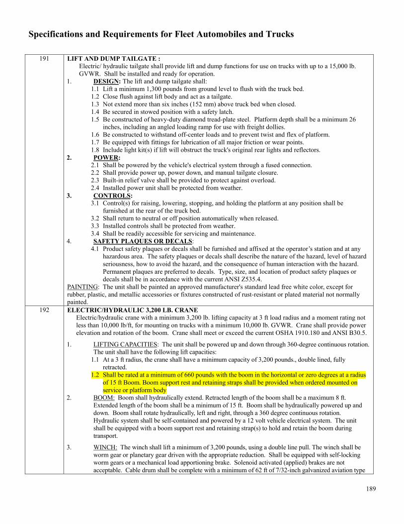
Specifications and Requirements for Fleet Automobiles and Trucks
189
191 LIFT AND DUMP TAILGATE : Electric/ hydraulic tailgate shall provide lift and dump functions for use on trucks with up to a 15,000 lb. GVWR. Shall be installed and ready for operation.
1. DESIGN: The lift and dump tailgate shall: 1.1 Lift a minimum 1,300 pounds from ground level to flush with the truck bed. 1.2 Close flush against lift body and act as a tailgate. 1.3 Not extend more than six inches (152 mm) above truck bed when closed. 1.4 Be secured in stowed position with a safety latch. 1.5 Be constructed of heavy-duty diamond tread-plate steel. Platform depth shall be a minimum 26
inches, including an angled loading ramp for use with freight dollies. 1.6 Be constructed to withstand off-center loads and to prevent twist and flex of platform. 1.7 Be equipped with fittings for lubrication of all major friction or wear points. 1.8 Include light kit(s) if lift will obstruct the truck's original rear lights and reflectors.
2. POWER: 2.1 Shall be powered by the vehicle's electrical system through a fused connection. 2.2 Shall provide power up, power down, and manual tailgate closure. 2.3 Built-in relief valve shall be provided to protect against overload. 2.4 Installed power unit shall be protected from weather.
3. CONTROLS: 3.1 Control(s) for raising, lowering, stopping, and holding the platform at any position shall be
furnished at the rear of the truck bed. 3.2 Shall return to neutral or off position automatically when released. 3.3 Installed controls shall be protected from weather. 3.4 Shall be readily accessible for servicing and maintenance.
4. SAFETY PLAQUES OR DECALS: 4.1 Product safety plaques or decals shall be furnished and affixed at the operator’s station and at any
hazardous area. The safety plaques or decals shall describe the nature of the hazard, level of hazard seriousness, how to avoid the hazard, and the consequence of human interaction with the hazard. Permanent plaques are preferred to decals. Type, size, and location of product safety plaques or decals shall be in accordance with the current ANSI Z535.4.
PAINTING: The unit shall be painted an approved manufacturer's standard lead free white color, except for rubber, plastic, and metallic accessories or fixtures constructed of rust-resistant or plated material not normally painted.
192 ELECTRIC/HYDRAULIC 3,200 LB. CRANE Electric/hydraulic crane with a minimum 3,200 lb. lifting capacity at 3 ft load radius and a moment rating not less than 10,000 lb/ft, for mounting on trucks with a minimum 10,000 lb. GVWR. Crane shall provide power elevation and rotation of the boom. Crane shall meet or exceed the current OSHA 1910.180 and ANSI B30.5.
1. LIFTING CAPACITIES: The unit shall be powered up and down through 360-degree continuous rotation. The unit shall have the following lift capacities:
1.1 At a 3 ft radius, the crane shall have a minimum capacity of 3,200 pounds., double lined, fully retracted.
1.2 Shall be rated at a minimum of 660 pounds with the boom in the horizontal or zero degrees at a radius of 15 ft Boom. Boom support rest and retaining straps shall be provided when ordered mounted on service or platform body
2. BOOM: Boom shall hydraulically extend. Retracted length of the boom shall be a maximum 8 ft. Extended length of the boom shall be a minimum of 15 ft. Boom shall be hydraulically powered up and down. Boom shall rotate hydraulically, left and right, through a 360 degree continuous rotation. Hydraulic system shall be self-contained and powered by a 12 volt vehicle electrical system. The unit shall be equipped with a boom support rest and retaining strap(s) to hold and retain the boom during transport.
3. WINCH: The winch shall lift a minimum of 3,200 pounds, using a double line pull. The winch shall be worm gear or planetary gear driven with the appropriate reduction. Shall be equipped with self-locking worm gears or a mechanical load apportioning brake. Solenoid activated (applied) brakes are not acceptable. Cable drum shall be complete with a minimum of 62 ft of 7/32-inch galvanized aviation type

Specifications and Requirements for Fleet Automobiles and Trucks
190
cable. Cable shall be minimum 5,600 lb breaking strength. Cable shall have a swagged-on eye. Eye shall be equipped with a swivel type traveling block, connected to the eye by means of a safety hook. Traveling block assembly shall be equipped with a minimum 1.65 ton capacity lifting hook. Lifting hook shall be equipped with a spring loaded safety latch. Load line shall be power up and down.
4. MOTOR: The winch shall be powered by a minimum 1.8 horsepower, 12 volt DC operated, reversible electric motor. Horsepower shall be sufficient for routine operation at rated capacity. A minimum of 24 ft of #1 battery cable with grommets, frame clips, high-current plug-in connector for the unit, and a terminal connector for the 12 volt vehicle battery shall be furnished.
5. CONTROLS: The operation of the unit shall be by a hand-held remote pendent type control, complete with minimum 18 ft. industrial grade extension cord and plug-in connector. All remote controlled relays necessary for operation shall be provided.
6. LOAD SENSOR: A load sensing device meeting OSHA requirements shall be furnished to prevent overloading. The sensor shall stop winch up, boom extension, and boom down operations, but shall allow power rotation, and hoist down operation.
7. ANTI-TWO BLOCK: The unit shall be equipped with a boom-tip-mounted anti-two block device which shall prohibit the traveling block or hook assembly from coming into contact with the boom.
8. OUTRIGGER(S): The unit shall have crane manufacturer-recommended hydraulic or manual slide-out, pin and crank down outrigger(s) which meet all applicable ANSI standards. The outrigger(s) shall be equipped with minimum 6 inch by 8 inch foot pad(s). JACK LEGS ARE NOT PERMITTED.
9. BASE PLATE: Shall be constructed of steel plate a minimum of ⅝ inch thick. The rectangular dimensions of the base plate shall be approximately 14 inches by 14 inches, with a range of tolerance of ± 2 inches.
10. MOUNTING: Crane shall be mounted in accordance with the crane manufacturer’s instructions. When mounted on a service, the service body must be factory reinforced as an OEM upgrade by the original manufacture of the body and should be rated to the total foot pounds of the crane installed. No aftermarket or shop fabricated reinforcements are acceptable.
11. LOAD CAPACITY CHART: A permanent load capacity chart with gravity activated boom angle indicator shall be located near the operator’s position, easily visible to the operator. The load capacity chart shall show rated load capacities at various radii resulting from different boom angles and lengths.
12. SAFETY PLAQUES OR DECALS: Safety plaques or decals shall be furnished and affixed at any hazardous area. The safety plaques or decals shall describe the nature of the hazard, level of hazard seriousness, how to avoid the hazard, and the consequence of human interaction with the hazard. Permanent plaques are preferred to decals. Type, size, and location of product safety plaques or decals shall be in accordance with the current ANSI Z535.4.
13. PAINTING: The unit shall be painted an approved manufacturer's standard lead free white color, except for rubber, plastic, and metallic accessories or fixtures constructed of rust-resistant or plated material not normally painted.
5. MANUAL(S): Manual(s) containing illustrated parts list(s) and operating and service instructions for the crane shall be delivered with each
195 DISABLE-Rear Doors lock/handles inoperable at factory. 196 (DELETE)-Rear Window Switch Delete (include rear power window switches operable by driver) 198 OUTRIGGERS (S) TO THE ELECTRIC/HYDRAULIC 3,200 LB. CRANE (OPTION 192): Single Outrigger –
The unit shall have crane manufacturer-recommended hydraulic or manual slide-out, pin and crank down outrigger(s) which meet all applicable ANSI standards. The Outrigger(s) shall be equipped with minimum 6 inch by 8 inch foot pad (s).
199 OUTRIGGERS (S) TO THE ELECTRIC/HYDRAULIC 4,000 LB. CRANE (OPTION 204): Duel Outrigger Assemblies – The unit shall have crane manufacturer-recommended hydraulic or manual slide-out, pin and crank down outrigger(s) which meet all applicable ANSI standards. The outrigger(s) shall be equipped with minimum 6 inch by 8 inch foot pad(s).
200 BODY, STATIONARY STAKE BODY, WOODEN FLOOR (See Section F and G of this specification) 201 DOORS-SLIDING SIDE DOOR (for Cargo and Passenger Vans) 202 DOORS- SWING –OUT Doors: Drivers side swing-out doors. for Cargo Vans) 203 DOORS-CARGO DOOR: Left Side, with RH Swing-Out Doors

Specifications and Requirements for Fleet Automobiles and Trucks
191
204 CRANE - ELECTRIC/HYDRAULIC 4,000 LB. CRANE (Series 930, 950, 960, 970, 980, 981,&990) Electric/hydraulic crane with a minimum 4,000 lb. lifting capacity at 4 ft load radius using single or double line only and a moment rating not less than 16,000 lb/ft for mounting on trucks with a minimum 11,000 lb.
1. LIFTING CAPACITIES: The unit shall be powered up and down through 360-degree continuous rotation. The unit shall have the following lift capacities:
1.1 At a 4 ft radius, the crane shall have a minimum capacity of 4,000 pounds, fully retracted. 1.2 Shall be rated at a minimum of 1000 pounds. with the boom horizontal at a radius of 16 ft.
2. BOOM: Boom shall hydraulically extend. Retracted length of the boom shall be a maximum 11’5” ft. Extended length of the boom shall be a minimum of 16 ft. Boom shall be hydraulically powered up and down. Boom shall rotate hydraulically, left and right, through a 360 degree continuous rotation. Hydraulic system shall be self-contained and powered by a 12 volt vehicle electrical system. The unit shall be equipped with a boom support rest and retaining strap(s) to hold and retain the boom during transport.
3. WINCH: The winch shall lift a minimum of 4,000 pounds, using a single or double line pull. The winch shall be worm gear or planetary gear driven with the appropriate reduction. Shall be equipped with self-locking worm gears or a mechanical load apportioning brake. Solenoid activated (applied) brakes are not acceptable. Cable drum shall be complete with a minimum of 80 ft of 5/16 inch galvanized aviation type cable. Cable shall be minimum 9800 lbs. breaking strength. Cable shall have a swagged-on eye. Eye shall be equipped with a swivel type traveling block, connected to the eye by means of a safety hook. Traveling block assembly shall be equipped with a minimum 1.65 ton capacity lifting hook. Lifting hook shall be equipped with a spring loaded safety latch. Load line shall be power up and down.
4. MOTOR: The winch shall be powered by a minimum 1.8 horsepower, 12 volt DC operated, reversible electric motor. Horsepower shall be sufficient for routine operation at rated capacity. A minimum of 25 ft .of #1 battery cable with grommets, frame clips, high-current plug-in connector for the unit, and a terminal connector for the 12 volt vehicle battery shall be furnished.
5. CONTROLS: The operation of the unit shall be by a hand-held remote pendent type control, complete with minimum 18 ft. industrial grade extension cord and plug-in connector. All remote controlled relays necessary for operation shall be provided.
6. LOAD SENSOR: A load sensing device meeting OSHA requirements shall be furnished to prevent overloading. The sensor shall stop winch up, boom extension, and boom down operations, but shall allow power rotation, and hoist down operation.
7. ANTI-TWO BLOCK: The unit shall be equipped with a boom-tip-mounted anti-two block device which shall prohibit the traveling block or hook assembly from coming into contact with the boom.
8. OUTRIGGER(S): The unit shall have crane manufacturer-recommended hydraulic or manual slide-out, pin and crank down dual outrigger(s) which meet all applicable ANSI standards. The outrigger(s) shall be equipped with minimum 6 inch by 8 inch foot pad(s). JACK LEGS ARE NOT PERMITTED.
9. BASE PLATE: Shall be constructed of steel plate a minimum of ⅝ inch thick. The rectangular dimensions of the base plate shall be approximately 14 inches by 14 inches, with a range of tolerance of ± 2 inches.
10. MOUNTING: Crane shall be mounted in accordance with the crane manufacturer’s instructions. When mounted on a service, the service body must be factory reinforced as an OEM upgrade by the original manufacture of the body and should be rated to the total foot pounds of the crane installed. No aftermarket or shop fabricated reinforcement and acceptable.
11. LOAD CAPACITY CHART: A permanent load capacity chart with gravity activated boom angle indicator shall be located near the operator’s position, easily visible to the operator. The load capacity chart shall show rated load capacities at various radii resulting from different boom angles and lengths.
12. SAFETY PLAQUES OR DECALS: Safety plaques or decals shall be furnished and affixed at any hazardous area. The safety plaques or decals shall describe the nature of the hazard, level of hazard seriousness, how to avoid the hazard, and the consequence of human interaction with the hazard. Permanent plaques are preferred to decals. Type, size, and location of product safety plaques or decals shall be in accordance with the current ANSI Z535.4.
13. PAINTING: The unit shall be painted an approved manufacturer's standard lead free white color, except for rubber, plastic, and metallic accessories or fixtures constructed of rust-resistant or plated material not normally painted.
MANUAL(S): Manual(s) containing illustrated parts list(s) and operating and service instructions for the crane
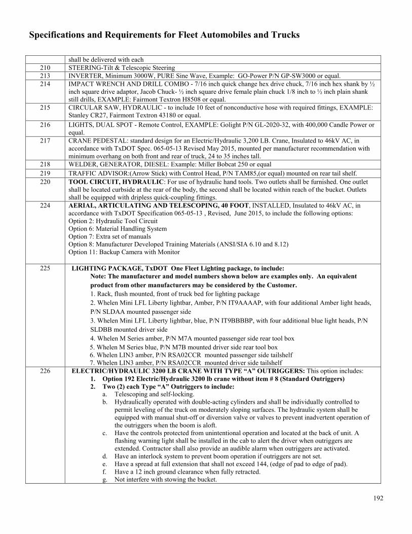
Specifications and Requirements for Fleet Automobiles and Trucks
192
shall be delivered with each 210 STEERING-Tilt & Telescopic Steering 213 INVERTER, Minimum 3000W, PURE Sine Wave, Example: GO-Power P/N GP-SW3000 or equal. 214 IMPACT WRENCH AND DRILL COMBO - 7/16 inch quick change hex drive chuck, 7/16 inch hex shank by ½
inch square drive adaptor, Jacob Chuck- ½ inch square drive female plain chuck 1/8 inch to ½ inch plain shank still drills, EXAMPLE: Fairmont Textron H8508 or equal.
215 CIRCULAR SAW, HYDRAULIC - to include 10 feet of nonconductive hose with required fittings, EXAMPLE: Stanley CR27, Fairmont Textron 43180 or equal.
216 LIGHTS, DUAL SPOT - Remote Control, EXAMPLE: Golight P/N GL-2020-32, with 400,000 Candle Power or equal.
217 CRANE PEDESTAL: standard design for an Electric/Hydraulic 3,200 LB. Crane, Insulated to 46kV AC, in accordance with TxDOT Spec. 065-05-13 Revised May 2015, mounted per manufacturer recommendation with minimum overhang on both front and rear of truck, 24 to 35 inches tall.
218 WELDER, GENERATOR, DIESEL: Example: Miller Bobcat 250 or equal 219 TRAFFIC ADVISOR:(Arrow Stick) with Control Head, P/N TAM85,(or equal) mounted on rear tail shelf. 220 TOOL CIRCUIT, HYDRAULIC: For use of hydraulic hand tools. Two outlets shall be furnished. One outlet
shall be located curbside at the rear of the body, the second shall be located within reach of the bucket. Outlets shall be equipped with dripless quick-coupling fittings.
224 AERIAL, ARTICULATING AND TELESCOPING, 40 FOOT, INSTALLED, Insulated to 46kV AC, in accordance with TxDOT Specification 065-05-13 , Revised, June 2015, to include the following options: Option 2: Hydraulic Tool Circuit Option 6: Material Handling System Option 7: Extra set of manuals Option 8: Manufacturer Developed Training Materials (ANSI/SIA 6.10 and 8.12) Option 11: Backup Camera with Monitor
225 LIGHTING PACKAGE, TxDOT One Fleet Lighting package, to include: Note: The manufacturer and model numbers shown below are examples only. An equivalent product from other manufacturers may be considered by the Customer. 1. Rack, flush mounted, front of truck bed for lighting package 2. Whelen Mini LFL Liberty lightbar, Amber, P/N IT9AAAAP, with four additional Amber light heads, P/N SLDAA mounted passenger side 3. Whelen Mini LFL Liberty lightbar, blue, P/N IT9BBBBP, with four additional blue light heads, P/N SLDBB mounted driver side 4. Whelen M Series amber, P/N M7A mounted passenger side rear tool box 5. Whelen M Series blue, P/N M7B mounted driver side rear tool box 6. Whelen LIN3 amber, P/N RSA02CCR mounted passenger side tailshelf 7. Whelen LIN3 amber, P/N RSA02CCR mounted driver side tailshelf
226 ELECTRIC/HYDRAULIC 3200 LB CRANE WITH TYPE “A” OUTRIGGERS: This option includes: 1. Option 192 Electric/Hydraulic 3200 lb crane without item # 8 (Standard Outriggers) 2. Two (2) each Type “A” Outriggers to include:
a. Telescoping and self-locking. b. Hydraulically operated with double-acting cylinders and shall be individually controlled to
permit leveling of the truck on moderately sloping surfaces. The hydraulic system shall be equipped with manual shut-off or diversion valve or valves to prevent inadvertent operation of the outriggers when the boom is aloft.
c. Have the controls protected from unintentional operation and located at the back of unit. A flashing warning light shall be installed in the cab to alert the driver when outriggers are extended. Contractor shall also provide an audible alarm when outriggers are activated.
d. Have an interlock system to prevent boom operation if outriggers are not set. e. Have a spread at full extension that shall not exceed 144, (edge of pad to edge of pad). f. Have a 12 inch ground clearance when fully retracted. g. Not interfere with stowing the bucket.

Specifications and Requirements for Fleet Automobiles and Trucks
193
NOTE: Addition of this option will increase the curb weight of the aerial device unit by 300 to 600 pounds. This weight, along with the weight of the aerial device, body, passengers, and fuel will be deducted directly from the chassis GVWR to determine payload capacity
227 ELECTRIC/HYDRAULIC 3200 LB CRANE WITH TYPE “H” OUTRIGGERS: This option includes: 1. Option 192 Electric/Hydraulic 3200 lb. crane without item # 8 (Standard Outriggers) 2. Two (2) each Type “H” Outriggers to include:
a. Telescoping and self-locking. b. Hydraulically operated with double-acting cylinders and shall be individually controlled to
permit leveling of the truck on moderately sloping surfaces. The hydraulic system shall be equipped with manual shut-off or diversion valve or valves to prevent inadvertent operation of the outriggers when the boom is aloft.
c. Have the controls protected from unintentional operation and located at the back of unit. A flashing warning light shall be installed in the cab to alert the driver when outriggers are extended. Contractor shall also provide an audible alarm when outriggers are activated.
d. Have an interlock system to prevent boom operation if outriggers are not set. e. Have a spread at full extension that shall not exceed 144, (edge of pad to edge of pad). f. Have a 12 inch ground clearance when fully retracted. g. Not interfere with stowing the bucket.
NOTE: Addition of this option will increase the curb weight of the aerial device unit by 300 to 600 pounds. This weight, along with the weight of the aerial device, body, passengers, and fuel will be deducted directly from the chassis GVWR to determine payload capacity.
228 Contractor shall furnish and install a 9,500lb. pull capacity electric winch. Winch shall be equipped with a remote control suitable for cab mounting and a 4 way, 12” roller fair lead. Winch shall be mounted on and protected by a chassis frame supported bumper/shelf. Shelf step shall be min. 3/8” tread plate steel. Contractor shall also fabricate and install an a-frame structure with a fixed sheave mounted at the apex of the a-frame. Sheave shall guide and serve as a fulcrum for the winch’s wire rope. A-frame shall be a minimum 2 1/4' in height and constructed of four members of minimum 1 ¼” diameter carbon steel pipe. The base of the a-frame shall be a min. of 3ft. in length. The center of the sheave and the winch drum shall be aligned perpendicular to the center line of the chassis frame width to minimize lateral stress on the a-frame. A-frame and bumper shall be painted black and shall not interfere with the opening of the hood. Contractor shall furnish and install two outriggers to be installed on the right and left corners of the front bumper. A red colored plastic marker shall be mounted to the top of the sheave and be a minimum 18” long.
231 OUTRIGGERS NARROW GAGE…in accordance with TxDOT Specification 065-05-13 Revised May 2015.
232 OUTRIGGERS MODIFIED "A" FRAME used for Aerial Devices…in accordance with TxDOT Specification 065-05-13 Revised May 2015.
258 SEAT FABRIC, VINYL 271 PARA-TRANSIT BODY 14 ADULTS, Stand up entry -Conversion of a full size van equipped with a raised roof
to a para-transit vehicle with provisions for stand-up entry, seating for fourteen (14) adult ambulatory passengers. Wheelbase upgrade (if required) to be included in the price of the body. Approximate Payload Allowance, 2,550 pounds. Overall Length, 256 inches. Refer to TX Fleet Specification for Para-transit Vehicles.
272 PARA-TRANSIT BODY: 10 ADULTS, 4 WHEELCHAIRS -Conversion of a full size van equipped with a raised roof to a para-transit vehicle with provisions for stand-up entry, seating for ten (10) adult ambulatory passengers and four (4) wheelchair positions along with the wheelchair lift and tie downs. Wheelbase upgrade (if required) to be included in the price of the body. Approximate Payload Allowance, 2,550 pounds. Overall Length, 256 inches. Refer to TX Fleet Specification for Para-transit Vehicles.
273 PARA-TRANSIT BODY: 8 ADULTS, 5 WHEELCHAIRS -Conversion of a full size van equipped with a raised roof to a para-transit vehicle with provisions for stand-up entry, seating for eight (8) adult ambulatory passengers and five (5) wheelchair positions along with the wheelchair lift and tie downs. Wheelbase, 176 inches. Approximate Payload Allowance, 2,550 pounds. Overall Length, 298 inches. Refer to TX Fleet Specification for Para-transit Vehicles.

Specifications and Requirements for Fleet Automobiles and Trucks
194
274 PARA-TRANSIT BODY: 2 ADULTS, 6 WHEELCHAIRS -Conversion of a full size van equipped with a raised roof to a para-transit vehicle with provisions for stand-up entry, seating for two (2) adult ambulatory passengers and six (6) wheelchair positions along with the wheelchair lift and tie downs. Wheelbase, 176 inches. Approximate Payload Allowance, 2,550 pounds. Overall Length, 298 inches. Refer TX Fleet Specification for Para-transit Vehicles.
275 TRANSMISSION, AUTOMATIC (for medium-duty trucks, Series 950 through 990) 278 FLOORING WITH RECESSED TRACK WITH WHEELCHAIR POSITIONS for Para-transit Vehicles 304 SEATS, Cloth. Front Bucket And Rear Bench. 306 FLOORS-Floor Covering To Be Carpet, With Front And Rear Floor Mats, 345 SUSPENSION-Heavy Service Suspension 350 BODY - TRUCK DUMP BODY, SPECIAL MATERIAL HANDLING 354 VAN BODY (CAB & CHASSIS APPLICATION): Unless otherwise specified, all units shall be furnished
complete with standard equipment and factory-installed accessories as listed in the manufacturer's printed literature for the models specified herein (but See Section A.4.1. and Section C.1.1.). The following items are minimum requirements for the models specified herein, and shall be provided whether shown as optional or standard equipment by the manufacturer. The following are some of those standard features or additional features as listed for these models. Please note any additional requirements following the table for each series number. These additional requirements listed below any table are in addition to, the standard. Contractors shall conform to OEM Builder’s Book or structural guidelines to ensure warranty and safety compliance.
Additional Equipment: The following equipment is also required in addition to that required above:
Body: • Body: Aluminum body or agency approved equal• Airbags: Driver and passenger side• Floor covering: Front vinyl• Logistic Track: Inlaid, 12-gauge steel, painted. E-Track or agency approved equal• Side Mirrors: trailer towing• Cab-access: sliding door in cargo• Interior Lights: 12-volt dome light with rear switch• Floor: Flat, 2 X 6 Dense Pine shiplapped, formed X-member-16 O.C., 3” X 1-1/2” single lip X-
member, 4” I beam longsills, or agency approved equal, undercoating• SCUFF: GALV STL TUFF SCUFF UP12"SIDES, GALV STL TUFF SCUFF UP12"FRONT• Lining: 3/” Full height plywood lining• Interior Lights: Dome light with rear switch, hot wired• Bulkhead: 6” setback with or without access• Front End: 6-14” radius composite corner wind deflector extruded aluminum front corners with
def. rad. 050, smooth• Undercoating: Required• Mud Flaps: standard supreme
Chassis: • Sidewalls: .040 pre-painted, side wall Z-posts on 16” centers• Roof: .032 Aluminum rood shin-seamless 1 piece, anti-snag roof bows on 24” centers• Exterior Lights: FMVSS standard 108 lights, standard taillight package• Rear End: Standard rear end w/door opening, galvanneal rear door frame• Rear Door: Overhead door, aluminum clad, 85-1/4” X 71”, maximum security lock on over 2 grab
handles – rear aluminum 12”Various lifts (i.e, rail type or tuckaway), in various weight ratings.
363 SEATS-Seats To Be Front Split Bench Or 40/20/40 Cloth Seats, Rear Seats To Be vinyl 380 MIRRORS- Outside Rearview, Power Adjustable, Foldaway 392 HEADLINER - HEADLINER TO COVER PASSENGER AREA ONLY 396 FLOORS- ALL WEATHER, Full Length Rubber Or Vinyl Floor Mat 398 SEATS-All Seats To Be Cloth, Front Bucket With Armrests (0)

Specifications and Requirements for Fleet Automobiles and Trucks
195
408 SEATS-Seats To Be Cloth, Front To Be High Back Or Captain Type With Arm Rest 424 SEATS - SEATS TO BE CLOTH, FRONT TO BE HIGH BACK 425 PARTITION-Metal Bulkhead Partition Behind Second Row Bench Seat Required From 427 MIRRORS - LEFT AND RIGHT EXTERIOR MIRRORS, MANUALLY ADJUSTED 433 WHEELBASE - UPGRADE WHEELBASE TO 172+ INCHES 435 HITCH - GOOSENECK TRAILER HITCH 444 OEM Service Contract- BUMPER TO BUMPER, 6 Year / 100,000 miles @ $0 Deductible 502 SWITCHES- Cutoff Switches. (Refer To Spec) 503 WHEELBASE - 172" For FULL SIZE 3/4TON, CREW CAB PICKUP TRUCK 508 UPGRADE-Upgrade to 19,500 GVWR 509 PTO Opening 512 UPGRADE-Upgrade to next body trim style 519 CAMERA, BACK UP CAMERA W/MONITOR 523 COLOR-Color Green Special Paint 525 HYDRAULIC JACK - 6 TON HYDRAULIC JACK 526 HEATER - ENGINE BLOCK HEATER WITH CORD 528 CRANE BODY-Re-enforced crane body with 84" CA dimension, Examples: Knapheide 6132DLHR-60J, Dakota
132-SB or equal (For use with 3200H Crane)529 INCREASE CRANE BODY SIZE (OPTION 528) FROM 84" CA TO 102" - 108" CA DIMENSION 533 LIGHT BAR-, LIGHT BAR, FULL FEATURE, LAW ENFORCEMENT - contractor must provide light bar,
mounting hardware, serial box and labor to mount the police pursuit LED overhead light bar according to manufacturer and customer provided instructions. Contractor will be required to route the cables/wiring to specific locations, but will not be required to complete the connections to power-up the light bar. Reference Brand/model - Whelen Legacy Duo Lightbar Model # GS8TX7.
536 INSTALLATION-DECAL INSTALLATION. Contractor provides labor to install the customer provided decal package
537 WINDOW TINT - AFTER-MARKET DEEP WINDOW TINT FOR LAW ENFORCEMENT VEHICLES - Contractor shall install high performance window tint capable of eliminating up to 98% of UV rays on the front and rear door glass of both passenger and drivers side doors and rear glass. Tint shall comply with all applicable State of Texas laws and shall have a legible window tint label that contains all the information required by the Department regarding light transmission and luminous reflectance of the film. The film and glass shall not have a light transmission of 35% or more: or a luminous reflectance of 35% or less. Parts (tint) and labor shall be warranted for a period of three (3) years from the date the vehicle is put into service. All warranty repairs will be performed at the Contractors location or at the DPS Fleet Operations Headquarters. Warranty repairs will be coordinated through DPS Fleet Operations Management.
538 STREET APPEARANCE PACKAGE DODGE : Includes: (1)18x7.5 Aluminum Wheels (2)Front reading/map lamps (3) Exterior Mirrors with Heating Element (4) Fog lamps (5) Front/Rear Climate Control Outlets (6) Full Length Floor Console (7) Illuminated Front Cup holders (8)Power Heated Mirrors with manual foldaway Example: Dodge Charger Code: AEB
547 GUN LOCK- DUAL VERTICAL GUN LOCK,PARTS & LABOR floor mounted (M-4 & shotgun) - contractor must furnish all parts and labor to install the vertical rear seat mount gun lock according to manufacturer and customer provided instructions. Referenced Brand/model - Jotto Desk PN 475-1026, or Equal (Chevrolet Tahoe - 465CLE/468CLE)
548 PACKAGE EMERGENCY EQUIP-emergency equipment console and computer mount package - contractor must furnish and install equipment console that includes armrest, face plates, cup holders, printer mount, & computer mount according to manufacturer and customer provided instructions. Referenced Brand/model - Jotto Desk Part # 425-6472, or Equal (Chevrolet Tahoe – 465CLE/468CLE).
551 EXHAUST-Vertical Exhaust (TDCJ Specific) 552 TIRES-24.5 Tires and Wheels (TDCJ Specific) 553 TIRES-Dual Tire Pressure Equalization Valves (TDCJ Specific)

Specifications and Requirements for Fleet Automobiles and Trucks
196
554 SERVICE-Balance Tires and Alignment (TDCJ Specific) 555 AUDIO-AM/FM/CD Player (TDCJ Specific) 557 COMPACTOR-20 Yard New Way Cobra Compactor (TDCJ Specific) 558 BODY -STEP VAN BODY FOR COMMERCIAL STRIP DOWN CHASSIS CAB, 22500 GVWR, UPS STYLE
BODY (950G SERIES) . Reference Brand: 22 ft Utilimaster Ford F-59 chassis, Bulkhead 93.5 X 81.0 with roll up doors and 4" Lowered Stepwell both sides (refer to Utilimaster specs)
562 FIFTH WHEEL - STATIONARY FIFTH WHEEL PER TxDOT 072-08-82OPTION 5.1 563 FIFTH WHEEL - AIR SLIDING TYPE FIFTH WHEEL PER TxDOT 072-08-82 OPTION 5.2 600 Automatic Transmission for Heavy Duty Trucks (Allison 4000HS or 4500RDS) per TxDOT specifications in this
document below specified Series 601 HEADLIGHTS WITH WIPERS per TxDOT specifications in this document below specified Series 602 MIRRORS - HOOD MOUNTED CONVEX MIRORS per TxDOT specifications in this document below
specified Series 603 ALARM - PARKING BRAKE ALARM per TxDOT specifications in this document below specified Series 604 INSPECTION - PRE-TRIP LIGHT INSPECTION per TxDOT specifications in this document below specified
Series 605 STEERING - TILT AND TELESCOPING STEERING per TxDOT specifications in this document below
specified Series 606 POWER TAKE-OFF per TxDOT specifications in this document below specified Series 607 WINCH - UPRIGHT WINCH per TxDOT specifications in this document below specified Series 608 RACK - HEADACHE RACK per TxDOT specifications in this document below specified Series 609 TAIL PIPE - ROLLING TAIL PIPE per TxDOT specifications in this document below specified Series 610 FIFTH WHEEL - OILFIELD BODY per TxDOT specifications in this document below specified Series 611 TOW DEVICES for Light Duty Trucks: Manufacturer’s Standard (This option is no longer available. Use Option
124) per TxDOT specifications in this document below specified Series 612 QUARTER FENDERS AND MUD FLAPS per TxDOT specifications in this document below specified Series 613 ENGINE BLOCK HEATER 110V per TxDOT specifications in this document below specified Series 614 FIFTH WHEEL - OILFIELD BODY per TxDOT specifications in this document below specified Series 615 MANUALS - EXTRA SET OF MANUALS FOR HEAVY DUTY TRUCKS per TxDOT specifications in this
document below specified Series. Includes: One(1) complete set of Operator's , Service and Parts manuals shall be provided at the time of delivery.
616 BUG SCREEN - FRONT END MOUNTED BEHIND GRILLE - Heavy Duty Trucks 618 SWITCH - BATTERY DISCONNECT SWITCH for Heavy Duty Trucks 620 PACKAGE - HEAVY HAUL TRACTOR GROUP PACKAGE - Includes GVWR: 62,000, GCWR: 135,000 per
TxDOT requirements 621 UPGRADE PACKAGE - CHASSIS UPGRADE TO MEET ASPHALT MAINTENANCE UNIT(AMU) , Per
TxDOT specifications below specified Series in this document AND to include following options from TX Fleet Specification(latest revision): Options: 16, 19, 34, 37, 57, 93, 94 & 275
622 BODY, 1500 gallon Highway Class Maintenance Body, Asphalt Maintenance Unit Per TxDOT specifications below specified Series in this document with 12’-0 Std. Spraybar.
623 SPRAYBAR EXTENSIONS - Per TxDOT specifications below specified Series in this document Option No. 1 624 SPRAYBAR NOZZLES - per TxDOT specifications in this document below specified Series, Option No. 2, The
size of the nozzle to be selected by the customer at the time of ordering 625 MECHANICAL POINTER GUIDE WITH HYDRAULIC LIFT - Per TxDOT specifications below specified
Series in this document Option No. 3 626 FILL LINE - THREE (3) INCH REAR MOUNTED FILL LINE - Per TxDOT specifications below specified
Series in this document Option No. 4 627 POWER WASH DOWN - Per TxDOT specifications below specified Series in this document Option No. 5 628 SPIRIT LEVELS - Per TxDOT 755-10-50 Option No. 6, Unit shall be equipped with two spirit levels mounted at
the rear of the unit on the driver side. 630 BOXES , SPRAYBAR EXTENSION STORAGE BOXES - Per TxDOT specifications below specified Series in
this document Option No. 8 631 BACK UP ALARM SYSTEM- Per TxDOT specifications below specified Series in this document Option No. 9
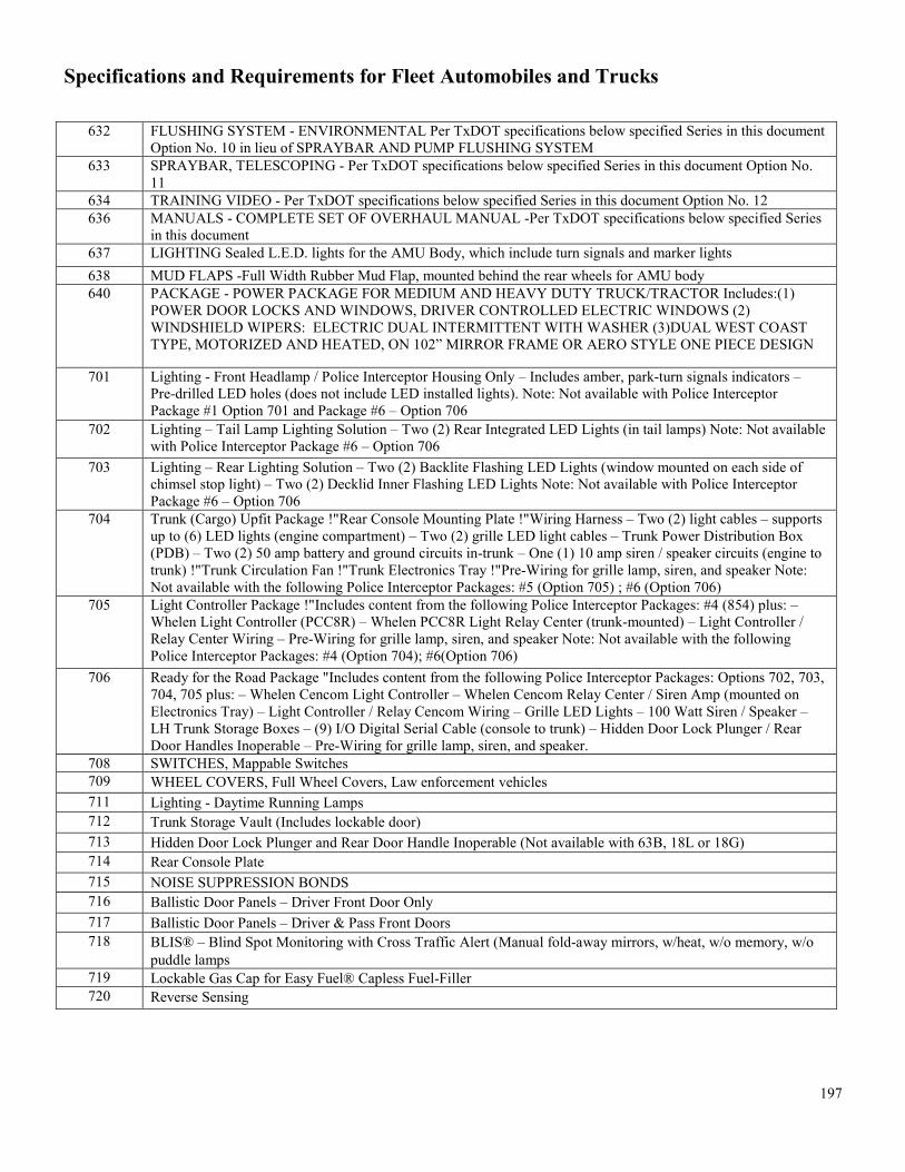
Specifications and Requirements for Fleet Automobiles and Trucks
197
632 FLUSHING SYSTEM - ENVIRONMENTAL Per TxDOT specifications below specified Series in this document Option No. 10 in lieu of SPRAYBAR AND PUMP FLUSHING SYSTEM
633 SPRAYBAR, TELESCOPING - Per TxDOT specifications below specified Series in this document Option No. 11
634 TRAINING VIDEO - Per TxDOT specifications below specified Series in this document Option No. 12 636 MANUALS - COMPLETE SET OF OVERHAUL MANUAL -Per TxDOT specifications below specified Series
in this document 637 LIGHTING Sealed L.E.D. lights for the AMU Body, which include turn signals and marker lights 638 MUD FLAPS -Full Width Rubber Mud Flap, mounted behind the rear wheels for AMU body 640 PACKAGE - POWER PACKAGE FOR MEDIUM AND HEAVY DUTY TRUCK/TRACTOR Includes:(1)
POWER DOOR LOCKS AND WINDOWS, DRIVER CONTROLLED ELECTRIC WINDOWS (2) WINDSHIELD WIPERS: ELECTRIC DUAL INTERMITTENT WITH WASHER (3)DUAL WEST COAST TYPE, MOTORIZED AND HEATED, ON 102” MIRROR FRAME OR AERO STYLE ONE PIECE DESIGN
701 Lighting - Front Headlamp / Police Interceptor Housing Only – Includes amber, park-turn signals indicators – Pre-drilled LED holes (does not include LED installed lights). Note: Not available with Police Interceptor Package #1 Option 701 and Package #6 – Option 706
702 Lighting – Tail Lamp Lighting Solution – Two (2) Rear Integrated LED Lights (in tail lamps) Note: Not available with Police Interceptor Package #6 – Option 706
703 Lighting – Rear Lighting Solution – Two (2) Backlite Flashing LED Lights (window mounted on each side of chimsel stop light) – Two (2) Decklid Inner Flashing LED Lights Note: Not available with Police Interceptor Package #6 – Option 706
704 Trunk (Cargo) Upfit Package !"Rear Console Mounting Plate !"Wiring Harness – Two (2) light cables – supports up to (6) LED lights (engine compartment) – Two (2) grille LED light cables – Trunk Power Distribution Box (PDB) – Two (2) 50 amp battery and ground circuits in-trunk – One (1) 10 amp siren / speaker circuits (engine to trunk) !"Trunk Circulation Fan !"Trunk Electronics Tray !"Pre-Wiring for grille lamp, siren, and speaker Note: Not available with the following Police Interceptor Packages: #5 (Option 705) ; #6 (Option 706)
705 Light Controller Package !"Includes content from the following Police Interceptor Packages: #4 (854) plus: – Whelen Light Controller (PCC8R) – Whelen PCC8R Light Relay Center (trunk-mounted) – Light Controller / Relay Center Wiring – Pre-Wiring for grille lamp, siren, and speaker Note: Not available with the following Police Interceptor Packages: #4 (Option 704); #6(Option 706)
706 Ready for the Road Package "Includes content from the following Police Interceptor Packages: Options 702, 703, 704, 705 plus: – Whelen Cencom Light Controller – Whelen Cencom Relay Center / Siren Amp (mounted on Electronics Tray) – Light Controller / Relay Cencom Wiring – Grille LED Lights – 100 Watt Siren / Speaker – LH Trunk Storage Boxes – (9) I/O Digital Serial Cable (console to trunk) – Hidden Door Lock Plunger / Rear Door Handles Inoperable – Pre-Wiring for grille lamp, siren, and speaker.
708 SWITCHES, Mappable Switches 709 WHEEL COVERS, Full Wheel Covers, Law enforcement vehicles 711 Lighting - Daytime Running Lamps 712 Trunk Storage Vault (Includes lockable door) 713 Hidden Door Lock Plunger and Rear Door Handle Inoperable (Not available with 63B, 18L or 18G) 714 Rear Console Plate 715 NOISE SUPPRESSION BONDS 716 Ballistic Door Panels – Driver Front Door Only 717 Ballistic Door Panels – Driver & Pass Front Doors 718 BLIS® – Blind Spot Monitoring with Cross Traffic Alert (Manual fold-away mirrors, w/heat, w/o memory, w/o
puddle lamps 719 Lockable Gas Cap for Easy Fuel® Capless Fuel-Filler 720 Reverse Sensing

Specifications and Requirements for Fleet Automobiles and Trucks
198
722 COLOR-Two-Tone Vinyl Package Includes: Labor and Materials to paint Hood, Roof and Trunk Deck Lid with White Vinyl. The vinyl paint must be factory installed or by the manufacturer's authorized upfitter. (Different color scheme may be substituted by the customer at the time of placing the order.
724 Vinyl Word Wrap – "POLICE" located on LH/RH sides of vehicle ("White" lettering) Note: May Not available with the other following Vinyl Wrap Packages:
725 Two-Tone Black & White Vinyl Wrap. Hood to be wrapped with white vinyl and all remaining panels to be painted black
728 Police Interior Upgrade Package "Cloth rear-seats "Floor mats, front and rear"1st Row Carpet Floor Covering with 2nd Row Vinyl "Floor Covering" Full floor console with unique police finish panels Note: Not available with the following Police Interceptor Packages: Options 704,705,706
729 Lighting - Dome Light - Red/White in Cargo Area 731 ROOF RACK SIDE RAILS-BLACK 735 Two-Tone Black & White Paint. Hood to be painted white and all remaining panels to be painted black
736 CARGO BOX, SCALE/EQUIPMENT – Must be installed. Dimensions shall be approximately 26.5" high x 45"
wide x 39.5" deep and must have the following: top of the box has an integrated inverted storage tray with rubberized liner and slots for attaching bungee cords or cargo net; consist of two drawers on the driver-side and one drawer and a storage cabinet on the passenger side, capable of holding four Haenni WL-101 scales. One driver side drawer must be approximately 7" in height with two removable dividers and capable of 250 pound capacity. Second driver side drawer must be approximately 11" in height with two removalbe dividers capable of 500 pound capacity and there must be a cutout center/rear to accommodate long weapons. The storage cabinet must have shelves available to install when scales are not stored and a partition/divider attached. The passenger side drawer must be approximately 5" in height, capable of 250 pount capacity, and removable. All drawers and doors must have a full length aluminum pull handle designed for one-hand operation and self-latching when closed. All drawers must have rubberized liners. An electrostatic painted "hardened" texture surface should be on all sides of the box. Referenced Brand: Ctech box # 27762 or equal for Chevrolet Tahoe (465CLE/468CLE)
737 CARGO BOX, EQUIPMENT CARGO BOX, Parts only, Installation is not required. Dimensions shall be approximately 26.5" high x 45" wide x 39.5" deep and must have the following: top of the box has an integrated inverted storage tray with rubberized liner and slots for attaching bungee cords or cargo net; consist of two drawers on the driver-side and one drawer and a storage cabinet on the passenger side, capable of holding four Haenni WL-101 scales. One driver side drawer must be approximately 7" in height with two removable dividers and capable of 250 pound capacity. Second driver side drawer must be approximately 11" in height with two removalbe dividers capable of 500 pound capacity and there must be a cutout center/rear to accommodate long weapons. The storage cabinet must have shelves available to install when scales are not stored and a partition/divider attached. The passenger side drawer must be approximately 5" in height, capable of 250 pount capacity, and removable. All drawers and doors must have a full length aluminum pull handle designed for one-hand operation and self-latching when closed. All drawers must have rubberized liners. An electrostatic painted "hardened" texture surface should be on all sides of the box. Referenced Brand: Ctech box # 27762 or equal for Chevrolet Tahoe (465CLE/468CLE)
738 Package - Upfit per TxDPS specification. Includes: (1) Front grille pre-wired for lights and siren speaker, (2) installation of Motorola Radio Harness (provided by TxDPS), (3) Installation of console mounting base (4) Supply and install power distribution block and harness with minimum 15 fused and time circuits with single power supply and circuit breaker, 911 Circuits P/N CH15 or equivalent, (5) Decal Package,(6) Supply and install Outer Edge with three (3) Whelen Ion Duo or equivalent lights on each side of third brake light (7) Supply and install red & blue lights on edge of rear liftgate, Whelen Ion Duo or equivalent (8) Supply and install window tint to both front windows to 35%, (9) Supply and install VHF antenna (mobile, coil with cables), Laird Technologies P/N B1322W or equivalent; and supply and install GPS antenna (with cables), Sharkee P/N GPSB4 or equivalent. Must be provided by a GM Authorized Upfitter

Specifications and Requirements for Fleet Automobiles and Trucks
199
739 Package - Upfit per TxDPS specification. Includes: (1) Front grille pre-wired for lights and siren speaker, (2) installation of Motorola Radio Harness (provided by TxDPS), (3) Installation of console mounting base (4) Supply and install power distribution block and harness with minimum 15 fused and time circuits with single power supply and circuit breaker, 911 Circuits P/N CH15 or equivalent, (5) Decal Package,(6) Supply and install Outer Edge with three (3) Whelen Ion Duo or equivalent lights on each side of third brake light (7) Supply and install red & blue lights on edge of rear liftgate, Whelen Ion Duo or equivalent (8) Supply and install window tint to both front windows to 35%, (9) Supply and install VHF antenna (mobile, coil with cables), Laird Technologies P/N B1322W or equivalent; and supply and install GPS antenna (with cables), Sharkee P/N GPSB4 or equivalent. Must be provided by a Ford Authorized Upfitter
743 LIGHTING, INOPERABLE DOME AND COURTESY LAMPS 753 PACKAGE- BASE PREP POLICE PACKAGE - for Dodge Charger Police RWD to include: (1) Front and Rear
Wire Harness(XPW), (2) Power Distribution Center (XWK), (3) Siren Speaker & Bracket (XWP), (4) Trunk Tray & Cooling Fan
754 PACKAGE-CONVENIENCE GROUP, Includes: Power 4-way Driver Seat Lumbar, Power 8-way Driver Seat, Power Adj Pedals, Power Driver/Passenger Seats, Power Driver/passenger Lumbar Adj
755 PACKAGE-PATROL PACKAGE - For Dodge Charger LE, Includes: Front and rear Wire Harness ,Front Corner LED Lamps ,Police Floor Console, Power Distribution Center, Rear Corner LED Lamp, Siren Speaker and Bracket(XWP), Trunk Tray and Cooling Fan(XWP)
757 PACKAGE- PATROL PACKAGE-For Dodge Charger to include: (1) Front and rear Wire Harness (XPW), (2) Front Corner LED Lamps (LNB),(3)Police Floor Console(CUG), (4)Power Distribution Center(XWK), (5)Push Bumper(MBR), (6)Rear Corner LED Lamp(LNU), (7)Siren Speaker and Bracket(XWP), Trunk Tray and Cooling Fan(XWP)
775 CONSOLE - MINI CONSOLE - Replace Full Console with Mini Console 777 KIT-TIRE RELOCATION: Contractor to provide and install spare tire relocation kit. Example: Jotto Desk Part #
425-3759 779 Dedicated CNG 2 Tank Rated 11 GGE (available on series #:658A) 780 Dedicated CNG 3 Tank Rated 16 GGE (available on series #:658A) 781 BI-FUEL CNG RATED 10 GGE with Tank Cover (available on series #:680C, 685C, 755C, 760C) 782 DEDICATED CNG RATED 20 GGE (available on series #:680C, 685C, 755C, 760C) 783 Dedicated CNG 3 Tank (available on series #:741A) 784 RAM - Upgrade to 5.7 HEMI Bi-Fuel CNG Engine (EZF) and 4x4 (available on series #:866C) 785 UNDERBED DEDICATED 20 GGE (available on series #:866C, 868C, 869C, 870C, 872C, 875C, 876C, 881C,
882C, 886C, 887C) 786 UNDERBED BI-FUEL CNG 10 GGE (available on series #:866C, 868C,869C, 870C, 872C, 875C, 876C, 881C,
882C, 886C, 887C) 787 IN-BED BI-FUEL CNG 20 GGE with Tank Cover (available on series #:866C, 868C,869C, 870C, 872C, 875C,
876C, 881C, 882C, 886C, 887C) 788 IN-BED BI-FUEL CNG 21 GGE with Tank Cover (available on series #:866C, 868C,869C, 870C, 872C, 875C,
876C, 881C, 882C, 886C) 790 6.0L V8 SFI GASEOUS (available on series #:868C,869C) 793 6.0L V8 SFI GASEOUS - 3-TANK CONFIGURATION, LIQUID PETROLEUM GAS (LPG) SYSTEM,
DEDICATED (available on series #:883C, 884C, 885C) 794 6.0L V8 SFI GASEOUS - 4-TANK CONFIGURATION, LIQUID PETROLEUM GAS (LPG) SYSTEM,
DEDICATED (available on series #:883C, 884C, 885C) 798 OEM BACK-UP ALARM SYSTEM. 799 OEM DAYTIME RUNNING LIGHTS. 800 OEM REVERSE SENSING SYSTEM. 801 OEM RUNNING BOARDS, COLOR BLACK. 802 OEM CNG/LPG GASEOUS ENGINE PREP PACKAGE. 803 UP-FITTER SWITCHES, CONTRACTOR SHALL PROVIDE A MINIMUM OF (4) FOUR UP-FITTER
SWITCHES, MOUNTED IN CAB AND ACCESSIBLE TO DRIVER ON RIGHT HAND SIDE

Specifications and Requirements for Fleet Automobiles and Trucks
200
805 OEM PHONE HANDS FREE DEVICE 806 OEM LONG BED IN LIEU OF SHORT 807 CAMERA SYSTEM, TWO CAMERA SYSTEMS, WITH IN-CAB MOUNTED 7” MONITOR 808 OEM STATIONARY FRONT GRILLE 809 MINIMUM 70 DEGREE FORWARD TILT HOOD 810 WINDOW TINT, CONTRACTOR SHALL INSTALL HIGH PERFORMANCE WINDOW TINT CAPABLE
OF ELIMINATING UP TO 98% OF UV RAYS ON THE FRONT AND REAR DOOR GLASS AND ANY OTHER GLASS THAT MAY BE BEHIND THE REAR DOORS OF BOTH PASSENGER AND DRIVERS SIDE, INCLUDING THE REAR WINDOW OR LIFTGATE GLASS. TINT SHALL COMPLY WITH ALL APPLICABLE STATE OF TEXAS LAWS AND SHALL HAVE A LEGIBLE WINDOW TINT LABEL THAT CONTAINS ALL THE INFORMATION REQUIRED BY LAW REGARDING LIGHT TRANSMISSION AND LUMINOUS REFLECTANCE OF THE FILM. THE FILM AND GLASS SHALL NOT HAVE A LIGHT TRANSMISSION OF 35% OR MORE: OR A LUMINOUS REFLECTANCE OF 35% OR LESS. PARTS (TINT) AND LABOR SHALL BE WARRANTED FOR A PERIOD OF THREE (3) YEARS FROM THE DATE THE VEHICLE IS PUT INTO SERVICE.
811 OEM Up-Fitter Switches – Contractor shall provide a minimum of (4) four Up-fitter Switches, mounted in cab accessible to driver on right hand side.
812 OEM Rearview Camera System (After-Market not acceptable) 813 HEADACHE RACK, NO LOUVER WINDOW GRILL WITH LIGHTS (for light-duty pickup trucks only): One
piece welded type headache rack shall include two (2) left and right side turn signals with brake lights and two (2) reverse lights that are integrated into the headache rack with wiring that is not exposed to the weather. All lights shall be L.E.D type. Material shall be a minimum 2” X .095 square tubing wall. A light-duty headache rack shall be provided to allow a mounting point for a light bar. The mounting shall be accomplished by the use of the most appropriate size bolts with nuts and flat washers to insure safe and secure mounting without causing damage to the bed of the vehicle. Headache rack shall be treated in a chemical bath or dip, or similarly treated for rust prevention prior to application of the final finish which shall consist of a black powder coat finish. Example: Roughneck Model No. BHD-BHRSANLWL or equal. Substitutes must be approved by the ordering agency.
814 TOOL BOX, SINGLE LID, HEAVY-DUTY. ALUMINUM, SMOOTH OR DIAMOND TREAD, LOW PROFILE APPLICATION: Dimensions shall be approximately 62 inches wide (overall width, approximately 72 inches) by 13 inches height, 20.0 inches deep. Example: Weather Guard Model No. R-127, Better Built Model No. 73010910, Camlocker Model No. CAM/S71LP or equal. Substitutes must be approved by the ordering agency.
815 Ground studs -- Two interior mounted left and right side M10 studs in cargo area. Driver side includes 5 feet of 8 gauge ground wire. GM Option #UT7 for Police Package (9C1) and Special Service Package (5W4), 465CLE, 468CLE
816 Grille Lamps and Siren Speaker Wiring – GM Option #6J3 for Police Package (9C1) and Special Service Package (5W4), 465CLE, 468CLE. Ford option 60A (466BLE) and 51G (475BLE)
817 Horn/Siren circuit wiring – In-line connection for customer furnished switch. GM Option #6J4 for Police Package (9C1) and Special Service Package (5W4), 465CLE, 468CLE
818 Cloth Bucket Seats – Power driver and passenger bucket seats in base cloth trim (center 20% section removed from 40-20-40 split). GM Option #9U3 for Police Package (9C1) and Special Service Package (5W4), 465CLE, 468CLE *** Note, this option request is similar to numbers 295, 304, 381, and 402, which probably contain some redundancies, but this does require both driver and passenger seats to be powered, which is not explicitly required by the existing options. ***
820 Siren/Speaker – 100 watt siren/speaker must be installed per manufacturer and DPS instructions. Ford option number 18X (466BLE) and 96P (475BLE). GM option is unknown, but this should be included on 465CLE/468CLE bids as well.
822 Badge Delete – Delete all "Interceptor" and "Special Service Police" badging. Ford option 16D (466BLE) and 19D (475BLE)
823 Painted Aluminum Wheels – Ford option 64E (466BLE) and 642(475BLE) 824 Ford SYNC – Ford option 53M (466BLE and 475BLE), 91M (881D)

Specifications and Requirements for Fleet Automobiles and Trucks
201
825 Cargo Wiring Upfit Package – Ford option 67G (466BLE) – Rear console plate, wiring harness and control system
826 Front Headlamp Lighting Solution – Ford option 66A (466BLE) and 661 (475BLE) – Police headlamp, includes base headlamp wit high-beam wig-wag function and (2) white LED side warning lights.
827 Front interior visor light bar – Ford option 96W (466BLE) – 2 backlit flashing, linear high-intensity LED lights (driver side red; passenger side blue), mounted inside the windshield glass.
828 Police wire harness kit (front) – Ford option 47C (466BLE) and 77E (475BLE) 829 Police wire harness kit (rear) – Ford option 21P (466BLE) and 51J (475BLE) 830 Tail Lamp Housing – Ford option 86T (466BLE) 831 Ultimate Wiring Package – Ford option 67U (466BLE) and 857 (475BLE) 832 GUN LOCK- DUAL VERTICAL GUN LOCK,PARTS & LABOR floor mounted (M-4 & shotgun) - contractor
must furnish all parts and labor to install the vertical rear seat mount gun lock according to manufacturer and customer provided instructions. Referenced Brand/model - Jotto Desk PN 475-1137 or Equal (Ford Police Interceptor Utility – 466BLE).
833 PACKAGE EMERGENCY EQUIP-emergency equipment console and computer mount package - contractor must furnish and install equipment console that includes armrest, face plates, cup holders, printer mount, & computer mount according to manufacturer and customer provided instructions. Referenced Brand/model - Jotto Desk part # 425-6476 or Equal (Ford Police Interceptor Utility 466BLE)
834 Cargo Box, Scale/Equipment, referenced brand: Ctech P/N ICB40-401 or equivalent for Ford PI Utility 835 Cargo Box, Scale/Equipment, Parts only, installation is not required. Referenced brand: Ctech P/N ICB40-401 or
equivalent for Ford PI Utility 836 Trunk electronics tray – Ford option 62D (475BLE) 837 GUN LOCK- DUAL VERTICAL GUN LOCK, PARTS & LABOR floor mounted (M-4 & shotgun) - contractor
must furnish all parts and labor to install the vertical rear seat mount gun lock according to manufacturer and customer provided instructions. Referenced Brand/model - Jotto Desk PN 475-0283 or Equal (Ford Police Interceptor Sedan – 475BLE).
838 110V AC Outlet – For cargo vans (685C) – Ford option 90L 839 Dual Batteries – For cargo vans (685C) – Ford option 634 840 Extra HD Alternator – For cargo vans(685C) – Ford option 63N 841 Rear Step – For cargo vans (685C) – Ford option 769 842 Hi Capacity Rear A/C – For cargo vans (685C) – Ford option 57V 843 High Roof – For cargo vans (685C) – Ford option R2X 844 Exterior Upgrade Pacakge – For cargo vans (685C) with high roofs – Ford option 18A 845 Steering Wheel Audio Controls – Ford option 62D (881D) 846 Premium Electronic AM/FM Stereo /w Single CD – Ford option 585 (881D) 847 Additional trim upgrade to 1LT – for Chevrolet Suburban (650C) 848 Upgrade body style to Premier – for Chevrolet Suburban (650C) 849 Luxury Package – for Chevrolet Suburban (650C) 850 Seats – Upgrade to leather – for Chevrolet Suburban (650C) 851 Seats – Power release second row bucket seats – for Chevrolet Suburban (650C) 852 Seats – Power folding third row seat 60/40 split bench – for Chevrolet Suburban (650C) 853 Side blind zone alert with lane change alert – for Chevrolet Suburban (650C) 854 Auxiliary rear battery – for Chevrolet Suburban (650C) 855 Push button, keyless start – for Chevrolet Suburban (650C) 856 Body-color bodyside moldings – for Chevrolet Suburban (650C) 857 Fog lamps – for Chevrolet Suburban (650C) 858 Rear liftgate, powered, hands free

Specifications and Requirements for Fleet Automobiles and Trucks
202
859 Chevrolet Mylink with navigation audio system 860 Park assist, front and rear – for Chevrolet Suburban (650C) 861 Rear cross traffic alert – for Chevrolet Suburban (650C) 862 Truck Bed Cover – Installed. Aluminum alloy construction with 400 pound load capacity, neoprene gasket and
gutters, allows complete bed access through 3 access points, security locks, black finish. Referenced brand: DiamondBack #270-CX. Substitutes must be approved by the ordering agency.
864 Police Floor Console – Dodge option CUG for Dodger Charger police vehicles 865 GUN LOCK- DUAL VERTICAL GUN LOCK,PARTS & LABOR floor mounted (M-4 & shotgun) - contractor
must furnish all parts and labor to install the vertical rear seat mount gun lock according to manufacturer and customer provided instructions. Referenced Brand/model - Jotto Desk PN 475-1032, or Equal (Dodge Charger police package).
866
Series 350A thru 869D, 872C, 872D, 876C, 876D, 881C, 881D, 882C, 882D, 886D, 887D
TxDOT Make Ready Option: Sedan, SUV, Van, Pickup: Please install all items in accordance with latest version of TxDOT Spec #928-04-99, Exhibit 1.
1. Install TxDOT supplied flying “T” Logos 2. Install TxDOT supplied global positioning system. 3. Install TxDOT supplied first aid kit. 4. Install TxDOT supplied lighting in accordance with latest version of
TxDOT Spec #928-04-99, Exhibit 1 5. Provide and install wiring harness for TxDOT supplied lightbar
(INSTALL LIGHT BAR). 6. Provide and install inverted chevrons to be installed in accordance with
latest version of TxDOT Spec #928-04-99, Exhibit 1. 7. Provide and install 2.5 lbs. ABC type, UL1A: 10 BC rated,
rechargeable fire extinguisher. 8. Provide and install “FIRE EXTINGUISHER INSIDE” label. 9. Provide and install “FIRST AID KIT INSIDE” label.
Series 870C, 870D, 875C, 875D, 888C, 888D, 929D thru 1286D
TxDOT Make Ready Option, Utility Body: Please install all items in accordance with latest version of TxDOT Spec #928-04-99
1. Install TxDOT supplied flying “T” Logos 2. Install TxDOT supplied global positioning system. 3. Install TxDOT supplied first aid kit. 4. Provide and install 2.5 lbs. ABC type, UL1A: 10 BC rated,
rechargeable fire extinguisher. 5. Provide and install “FIRE EXTINGUISHER INSIDE” label. 6. Provide and install “FIRST AID KIT INSIDE” label. 7. Provide inverted chevrons to be installed in accordance with latest
version of TxDOT Spec #928-04-99, Exhibit 1 883D/883DPT, 884C, 884D, 885C/885CPT, 929D thru 1000D
TxDOT Make Ready Option, Dump Body: Please install all items in accordance with latest version of TxDOT Spec #928-04-99
1. Install TxDOT supplied flying “T” Logos 2. Install TxDOT supplied global positioning system. 3. Install TxDOT supplied first aid kit. 4. Provide and install TxDOT supplied inverted chevrons to be installed
in accordance with latest version of TxDOT Spec #928-04-99, Exhibit 1
5. Provide and install 2.5 lbs. ABC type, UL1A: 10 BC rated, rechargeable fire extinguisher.
6. Provide and install “FIRE EXTINGUISHER INSIDE” label.

Specifications and Requirements for Fleet Automobiles and Trucks
203
7. Provide and install “FIRST AID KIT INSIDE” label.
867 In-Bed Bi-Fuel Propane 30 GGE With Tank Cover andToolbox Cover 868 17 GGE in bed Bi-Fuel With Tank Cover and Tool Box Cover 869 POWER PACKAGE - OEM Power Package to include power door locks, power windows, power mirrors, cruise
control and tilt steering wheel. 870 Power locks and windows (a required standard) 871 Extended Cab 872 Extended High Roof 873 Crew Cab 874 For 1200D: HEADACHE RACK – Aluminum, Heavy-duty, constructed as normally furnished with a truck of
this size. Headache rack shall be bolted to frame and include a chain tray, chain rack, and window with jailbars. Headache rack shall include a riser which will extend the height of the cab and include a top mount light bar pad measuring approximately 51” wide so that a light bar can be added by TxDOT personnel. In lieu of spring assisted post in (1200D TxDOT specifications in this document) a swinging hose hanger bar may be provided.
875 WET KIT/PTO/PUMP – Unit shall have a wet kit so that hydraulic power can be provided to transport trailers. The wet kit shall be provided and installed and must include:
1.1. An inline relief valve to prevent pressure build-up if trailer lines are not properly connected.
1.2. A transmission mounted PTO and direct mount pump shall be installed on the truck transmission. The pump shall be supported with an external pump support bracket mounted to the transmission. PTO shall be provided that is clutch shift or “hot shift” type and rated for use with the automatic transmission required for this application. The pump shall be capable of 15 to 25 gpm via a flow control valve, and shall provide a minimum 2400 psi hydraulic pressure.
1.2.1. The pump shall be controlled through a speed device that will automatically engage the pump at the proper engine RPM and will not allow engagement unless the engine is under 750 RPM and the truck transmission is in the neutral position. A gear type pump shall be provided with a bypass/pressure relief valve that is plumbed back to reservoir.
1.2.2. Dash mounted PTO controls shall include: Switch for electric/air solenoid, PTO hour meter, and “PTO engaged” light. Shall include all associated wiring and piping.
1.2.3. PTO/Pump shall automatically disengage when the RPM exceeds manufacturer’s recommended RPM.
1.2.4. All valves, fittings, lines, filters, and quick coupler connections necessary for trailer operation shall be included and installed.
1.3. An aluminum, saddle style, dual port, hydraulic reservoir shall be mounted behind cab and be a minimum of 50 gallon capacity.
1.4. Wet kit shall be filled to capacity with SAE 10 hydraulic oil meeting MIL-L-46152 specifications. Hoses will remain with truck when disconnected from trailer and will be long enough to allow maximum articulation of truck and trailer without stretching. A spring assisted post will be used to prevent hoses and all wires going to the trailer from tangling, stretching or contacting drive line or other parts. One-quarter (1/4) turn ball valves will be installed to isolate the reservoir (suction and

Specifications and Requirements for Fleet Automobiles and Trucks
204
return lines) for service and maintenance. (refer to 1200D TxDOT specifications in this document)
876 Dynatest 1295 Friction Measurement Skid System Model or Equal 877 Gooseneck Utility Body 879 21 under Body Bifuel LPG 881 Front Axle 16,000 GVWR (986D) 882 Material Handling System, Fiberglass JIB, minimum 800 lb. capacity 883 Rear Axle, 23,000 GVWR 884 4000 Gallon Water Tank Assembly with 6 Spray Nozzels and 50' ft.Hose Reel 885 Rear Tandem Axles, 40,000 GVWR 886 Tandem axle tire pressure equalization System 887 Reflective Triangle Kit 888 20' Ft. Stationary Stake Body, Steel Floor 889 Stationary Platform Body, Steel Floor 890 Max Speed Electronically governed at 65 MPH 891 Cruise Control Speed Electronically Governed at 65 MPH 892 Delete Front Frame Extensions 893 PTO Hour Meter 894 POWER TAKE OFF (PTO), HYDRAULIC WINCH, STEEL HEADACHE RACK, AND TOOL BOXES,
MUST INCLUDE ALL TxDOT SPECS IN 1286D IN ATTACHMENT D 895 ALUMINUM HEADACHE RACK, MUST INCLUDE ALL TxDOT SPECS IN 1286D IN ATTACHMENT D 896 ROLLING TAIL PIPE, MUST INCLUDE ALL TxDOT SPECS IN 1286D IN ATTACHMENT D 897 FIFTH WHEEL, CAST STEEL, 36 INCHES, MUST INCLUDE ALL TxDOT SPECS IN 1286D IN
ATTACHMENT D 898 QUARTER FENDERS AND MUD FLAPS, MUST INCLUDE ALL TxDOT SPECS IN 1286D IN
ATTACHMENT D 899 FIFTH WHEEL OILFIELD BODY, MUST INCLUDE ALL TxDOT SPECS IN 1286D IN ATTACHMENT D 900 GIN POLES, MUST INCLUDE ALL TxDOT SPECS IN 1286D IN ATTACHMENT D 901 AIR COMPRESSOR 902 Fiberglass Bucket/w Door, 24” x 42” x 42” with Red and White, 8" Chevron Markings (950D) 903 Electric over hydraulic lift gate (950D) 904 Blind Spot Alert 905 Cross Traffic Alert and Assist 906 Lane-Keeping Alert and Assist 907 Adaptive Cruise Control with Active Braking 908 Pedestrian and Forward Collision Detection, Warning and Active Braking
For AMU options Reference Specifications below specific Series for detailed specifications per option
For Aerial Options Reference Specifications below specific Series for detailed specifications per option (950D & 986D)
For TT (Truck,
Tandem) see 1000D
Reference Specifications below specific Series for detailed specifications per option

Specifications and Requirements for Fleet Automobiles and Trucks
205
SECTION E - REQUIREMENTS FOR DUMP BODIES - CONTRACTOR'S, PLATFORM, AND STAKE BODIES
The specific requirements for the Contractor's, Platform, and Stake Dump Bodies are given in Paragraphs F.1, F.2, and F.3, respectively. Section F.4, Installation and Mounting, and Section F.5, Painting, cover these requirements for all three types of bodies. Required dimensions are nominal.
E.1. CONTRACTOR'S TYPE DUMP BODY (See Options 178 through 183):
Sizes Available: 12’, 14’ & 16’ long Standard Features:
Fold-down sides (both sides of bed). The contractor's bed must have 14 - 18 inch max. side height, with brackets for nominal 2 inch sideboards. Body to be constructed of minimum 10 gauge steel.
10 gauge high strength steel front and side construction with formed sloping top rail. Front is fully welded to corner posts and front cross member for maximum strength. Sides have continuously welded vertical supports with drain holes. Equipped with brackets for 2” nominal side board extensions. End heights available in 20”. Clearance lights located high on rear corner posts and three light cluster (Identification lights) located in rear apron are recessed shock resistant rubber mounted. Fully boxed high strength steel construction tail gate with two vertical braces. 10 gauge high strength steel two-piece floor with 2” radius corners.
NOTE: A contractor’s type dump body has low profile panels for easy access from the ground.
BODY SIZES AND DIMENSIONS - The front and rear of the body shall be 6 inches higher than the sides. The sizes and dimensions of the bodies used on the various truck series shall be as follows:
1.1.1. Dimensions of the bodies shall be as shown for the truck series listed in the following table:
Series Number Wheelbase (nominal) Cab-to-Axle (nominal) Recommended Body Length Body Width
930 135.5 inches 60/84 inches 96/120 inch 70-84 inches950 128 inches 60 inches 96 inches 84 inches 960 - 990 126 inches 84 inches 98 inches 84 inches 960 - 990 150 inches 84 inches 120 inches 84 inches
1.1.2. Dump Body Capacities: When so specified in the Invitation for Bid, medium-duty trucks shall be equipped with dump bodies having capacities as follows: SERIES CAPACITY (cubic yards) 930 2-3960 3 970, and, 980 4 985, and 990 5 Not available on Series 971 and 981.
1.2. STEEL: The contractor's type dump body (including floor) shall be constructed from 0.1345 inch high-strength low-alloy steel (minimum yield point of 30,000 PSI and minimum tensile strength of 40,000 PSI) conforming to ASTM Standards A-607; or 0.1345 inch high carbon steel may be used. Standard AISI. tolerances are allowed for the metal thickness specified.
1.3. CONSTRUCTION AND COMPONENT REQUIREMENTS: Body shall include but not be limited to the following components: 1.3.1. Braces: Body shall have tapered box type side braces installed with continuous weld as follows:
1.3.1.1. 96 inch body: At least 2 braces on each side and 1 at each rear corner. 1.3.1.2. 120 inch body and above: At least 3 braces on each side and 1 at each rear corner.
1.3.2. Cross Members: Cross member spacing shall be the manufacturer's standard spacing. Cross members which form the front and rear outer box frame or to which the hoist is anchored shall be 3 inch minimum. 4.1 pound-foot structural steel channel. The other cross members shall be either the above structural steel channel or minimum 3 inch, 2.98 pound-foot high-strength junior I-beam. If a cross member must be cut to provide hoist clearance, this member may be 3/8 inch by 3 inch by 1-1/2 inch steel angle. Only 1 cross member may be constructed of steel angle and only then if it must be cut to provide hoist clearance. Body shall have cross members as follows:

Specifications and Requirements for Fleet Automobiles and Trucks
206
1.3.2.1. 96 inch body: A minimum of 7 cross members. 1.3.2.2. 120 inch body: A minimum of 9 cross members.
1.3.3. One-half Cab Protector: One-half cab protector shall cover approximately one-half of the truck cab (minimum 20 inch overhang). The material shall be as specified in Section 1.2.(above).
1.3.4. Back-up Alarm: Unit shall be complete with back-up alarm in compliance with applicable OSHA requirements.
1.3.5. Floor/Sidewall Joints: The joint between the side and floor of the body shall be one of the following types of construction to facilitate body clean-out: 1.3.5.1. A 2 inch minimum radius, or, 1.3.5.2. Body sheet with a 2 inch minimum 45 degree break (no welding) or, 1.3.5.3. Square corners. reference (price being equal) will be given in the above order.
1.3.6. Hoist and Hoist Sub-frame: The design of the hoist shall be the one customarily offered to the commercial trade for the body and hoist specified here. Hoist shall be double acting and have a positive stop incorporated to prevent hoist from reversing or locking up, and shall be complete. 1.3.6.1. Power hoists for two cubic yard dump bodies shall be equipped with a 12 volt electric/hydraulic drop
hinge low profile scissors hoist. A hydraulic type is preferred where available. 1.3.6.2. Power hoists for 3 and 4 cubic yard capacities shall be NTEA minimum Class 20 arm type; on 96
inch dump body and minimum Class 30 arm type; on 120 inch dump body from current chart on classification in effect. Power hoists for 5 cubic yard capacities shall be NTEA minimum Class 40 arm type on both the 96 inch and the 120 inch dump bodies. The following paragraphs (1.3.6.3 through 1.3.6.7) apply only to 3-5 cubic yard bodies:
1.3.6.3. The 96-120 inch dump body hoist shall have a 2 inch minimum diameter piston rod with a nominal stroke of 13-1/2 inches.
1.3.6.4. The 144 inch dump body hoist shall have a 2-3/16 inch minimum diameter piston rod with a nominal stroke of 20 inches.
1.3.6.5. The hoist shall have an anti-friction bearing pump with a minimum capacity of 12.7 GPM at 1,000 RPM and 1,000 PSI (sleeve bearing pump is not acceptable) and a hoist cylinder bore of not less than 7 inches".
1.3.6.6. Power hoists shall have at least a 3-stage valve to: (1) raise, (2) hold and (3) lower the body. 1.3.6.7. Hoist manufacturer's identification plate shall show the hoist model, class, and serial numbers.
NOTE: HOIST MUST BE REPAIRABLE TYPE HAVING REPLACEABLE BEARINGS, GASKETS, SEALS, AND OTHER LESS DURABLE PARTS.
1.3.7. Longitudinal Sills: A minimum of 2 are required which shall be manufactured from minimum 5 inch, 6.7 pound-foot structural steel channel or 5 inch, 10 pound/foot steel I-beam.
1.3.8. Power-Take-Off (PTO): PTO for dump operation shall be at least single speed. The output shaft shall have a speed (RPM) of not less than 50 percent or more than 80 percent of engine RPM. The output shaft shall have a speed (RPM) of approximately 90 percent on diesel engines.
NOTE: PTO MUST BE REPAIRABLE TYPE HAVING REPLACEABLE BEARINGS, GASKETS, SEALS, AND OTHER LESS DURABLE PARTS.
NOTE: Some light-duty trucks with automatic transmissions require an electric-powered PTO if ordered. If furnished, it shall be equipped with in-cab push-button or cable controls.
1.3.9. Rub Rails: Body shall have rub rails with a minimum slope of 30 degrees, constructed from 0.1345 inch steel (standard AISI. tolerances) and installed the full length of both sides and the tailgate.
1.3.10. Safety Strut (Brace): Each body shall be equipped with a "safety strut" designed to support the empty dump body in a raised position at an angle of approximately 45 degrees from the hoist sub-frame. The safety strut (brace) shall conform to OSHA Regulations, Section 1926.601 Motor Vehicles (b) (10) Trucks with Dump Bodies.
1.3.11. Sideboard Slots: The body shall have slots in the sides to accommodate sideboards.
1.3.12. Tailgate: Body shall be equipped with a double acting tailgate. Tailgate shall be designed and installed to close flush with body, and eliminate/minimize material loss between the tailgate and the dump body when chained in

Specifications and Requirements for Fleet Automobiles and Trucks
207
the horizontal position. The design and installation of the tailgate shall also prevent damage to the body/lights/reflectors when the tailgate is unlatched and deployed. Manufacturer's standard bracing shall be installed by continuous weld. Inner and outer panels of the tailgate shall also be connected by continuous weld. Spot welding is not acceptable. The tailgate shall be 6 inches higher than the sides of the body and shall consist of, but shall not be limited to, the following:
1.3.12.1. Upper Hinges and Hinge Pins: The tailgate shall be fitted with upper offset hinges of minimum 0.75 inch thick steel plate. These hinges shall not protrude above the sideboard gussets. The hinge pins shall be minimum 1 inch diameter. Supports made from minimum 0.5 inch thick steel shall be provided for each end of both upper hinge pins. Drilling of the sideboard gussets and reinforcing with minimum 0.375 inch thick steel plate for the upper hinge support is acceptable. Means shall be provided for adjusting the amount of tailgate opening when opened at the bottom and hinged at the top. Tailgate hinge pins shall be constructed with stops, to prevent lateral tailgate movement or accidental unlatching.
1.3.12.2. Lower Body Hardware and Hinge Pins: The lower body hardware on the tailgate shall be overhead hook type latch designed to hook and retain the hinge pins in supports on each side of the tailgate. The diameter of the lower hinge pins shall be minimum 1.25 inches. Means shall be provided to hold the tailgate in the same plane as the dump body floor when opened at the top and hinged at the bottom.
1.3.12.3. Operation and Control: A lever control for securing and releasing the lower tailgate latches shall be provided. This lever control shall be positioned on front of the body at the left so that operation of the lever shall not prevent opening the left cab door.
E.2 PLATFORM TYPE DUMP BODY (See Options 157, 162, 177, and 190):
2.1. BODY SIZES AND DIMENSIONS: The sizes and dimensions of the bodies used on the various truck series shall be asfollows: 2.1.1.Length: 144 inch minimum unless otherwise specified in the Invitation for Bid. 2.1.2.Width:
2.1.2.1. Light-Duty Truck Bodies: Minimum 80 inches to maximum 84 inches unless otherwise specified in the Invitation for Bid.
2.1.2.2. Medium-Duty Truck Bodies: Minimum 94 inches to maximum 96 inches unless otherwise specified in the Invitation for Bid.
2.2. FLOORING: 2.2.1.Steel: Steel platform type dump bodies (including floor) shall be constructed from 0.1345 inch high-strength low-
alloy steel (minimum yield point of 50,000 PSI and minimum tensile strength of 70,000 PSI) conforming to ASTM standards A-606; or 0.1345 inch high carbon steel may be used. Standard AISI tolerances are allowed for the metal thickness specified.
2.2.2.Wood: Wood platform type dump bodies (including floor) shall be constructed from 1-1/2 inch finished thickness, kiln-dried, Womanized or Penta-treated lumber, free from such defects as loose knots, knotholes, excessive warp, or edge splits. Each section shall be securely fastened to each cross member by recessed screws or bolts and installed flush with side rails.
2.3. CONSTRUCTION AND COMPONENT REQUIREMENTS: Body shall include but shall not be limited to the following components: 2.3.1.Rails:
2.3.1.1. Steel Body: The floor edges shall be enclosed with minimum 5 inch, 12-gauge, high-strength steel channel rails installed on both ends and on both sides.
2.3.1.2. Wood Body: The floor edges shall be enclosed with rails installed on both ends and on both sides as follows:
2.3.1.2.1. End Rails: Minimum 12-gauge formed steel channel.
2.3.1.2.2. Side Rails: Minimum 11-gauge formed steel channel.
2.3.2.Cross Members: Cross members shaping shall be the manufacturer's standard spacing with a minimum of 8 cross

Specifications and Requirements for Fleet Automobiles and Trucks
208
members on dump bodies spacing should be a minimum of 12” centers (including front and rear members) which shall be minimum 3 inch, 4.1 pound-foot structural steel channel, 3 inch, 2.98 pound-foot high-strength steel junior I-beam , or 4 inch formed, 11-gauge steel channel.
2.3.3.Hoist and Hoist Sub-frame: Body shall be equipped with a full length hoist sub-frame of not less than 0.250 inch steel channel. The design of the hoist shall hydraulic and be one customarily offered to the commercial trade for the body and hoist specified here. Hydraulic hoist shall be double arm lift type and shall have a positive stop incorporated to prevent hoist lift arms from reversing or locking up, and shall be complete with automotive drive parts. May be equipped with a single cylinder, scissor type hoist in lieu of the double arm lift type.
NOTE: HOIST SUB-FRAME NOT REQUIRED WITH SCISSOR TYPE HOIST.
2.3.3.1. The hoist shall have an anti-friction bearing pump with a minimum capacity of 12.7 GPM at 1,000 PSI (Sleeve-bearing pump is not acceptable) and a hoist cylinder bore of not less than 7 inches; or,
2.3.3.2. The hoist shall have an anti-friction bearing pump with a minimum capacity of 10.9 GPM at 1,000 RPM and 3,000 PSI with hoist cylinder bore of not less than 5 inches.
2.3.3.3. Power hoists shall have at least a 3-stage control valve to: (1) raise, (2) hold and, (3) lower the body.
2.3.3.4. Power hoist shall be NTEA minimum Class 30 arm type or Class D scissor type on 144 inch body from current chart on classifications in effect.
2.3.3.5. Hoist manufacturer's identification plate shall show the hoist model, class, and serial numbers..
NOTE: HOIST MUST BE REPAIRABLE TYPE HAVING REPLACEABLE BEARINGS, GASKETS, SEALS, AND OTHER LESS DURABLE PARTS.
2.3.4.Longitudinal Sills: A minimum of 2 are required which shall be manufactured from minimum 5 inch, 6.7 pound-foot structural steel channel or 5 inch, 10 pound-foot steel I-beam.
2.3.5.Power-Take-Off (PTO): PTO for dump operation shall be at least single speed. The output shaft shall have a speed (RPM) of not less than 50 percent or more than 80 percent of engine RPM. The output shaft shall have a speed (RPM) of approximately 110 percent on diesel engines.
NOTE: PTO MUST BE REPAIRABLE TYPE HAVING REPLACEABLE BEARINGS, GASKETS, SEALS, AND OTHER LESS DURABLE PARTS.
NOTE: Some light-duty trucks with automatic transmissions require an electric-powered PTO, if ordered. If furnished, it shall be equipped with in-cab push-button or cable controls.
2.3.6.Protector, Cab (Bulkhead Type): Body shall be equipped with a bulkhead type cab protector. This protector shall be designed to prevent shifting of load and penetrating or crushing of the driver's compartment. It shall be constructed of minimum 11-gauge steel plate with a window to provide visibility. The window shall be made of minimum 11-gauge diamond-punched steel, or covered with minimum 9-gauge expanded metal diamond mesh. Cab protector dimensions shall be designed to fit the truck cab and shall not interfere with the driver's rearward visibility.
Cab protector shall be mounted using knee-brace style reinforcements welded to the bottom of the outer body rail. Top-mounted angle gusset type mounting is not acceptable.
2.3.7.Safety Strut (Brace): Body shall be equipped with a "safety strut" designed to support the empty dump body in a raised position at an angle of approximately 45 degrees from the truck frame. The safety strut (brace) shall conform to OSHA. Regulations, Section 1926.601 Motor Vehicles (b) (10) Trucks with Dump Bodies.
2.3.8.Stake Pockets: Body shall have a minimum of 5 stake pockets on each side and a minimum of 4 on each end.
2.3.9.Operating Lever Latch: Body shall be equipped with a latch or other device which will prevent accidental starting or tripping of the mechanism.
2.3.10. Trip Handles: Trip handles for tailgates of dump bodies shall be so arranged that, in dumping, the operator will be in the clear.
E.3 STAKE TYPE DUMP BODY (See Options 161, 168, 176, and 186):
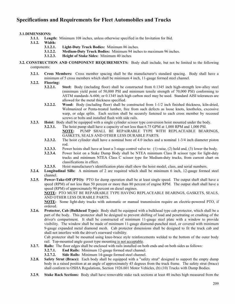
Specifications and Requirements for Fleet Automobiles and Trucks
209
3.1. DIMENSIONS: 3.1.1. Length: Minimum 108 inches, unless otherwise specified in the Invitation for Bid. 3.1.2. Width:
3.1.2.1. Light-Duty Truck Bodies: Minimum 86 inches. 3.1.2.2. Medium-Duty Truck Bodies: Minimum 94 inches to maximum 96 inches. 3.1.2.3. Height of Stake Sides: Minimum 40 inches
3.2. CONSTRUCTION AND COMPONENT REQUIREMENTS: Body shall include, but not be limited to the following components:
3.2.1. Cross Members: Cross member spacing shall be the manufacturer's standard spacing. Body shall have a minimum of 5 cross members which shall be minimum 4 inch, 11-gauge formed steel channel.
3.2.2. Flooring: 3.2.2.1. Steel: Body (including floor) shall be constructed from 0.1345 inch high-strength low-alloy steel
(minimum yield point of 50,000 PSI and minimum tensile strength of 70,000 PSI) conforming to ASTM standards A-606; or 0.1345 inch high carbon steel may be used. Standard AISI tolerances are allowed for the metal thickness specified.
3.2.2.2. Wood: Body (including floor) shall be constructed from 1-1/2 inch finished thickness, kiln-dried, Wolmanized or Penta-treated lumber, free from such defects as loose knots, knotholes, excessive warp, or edge splits. Each section shall be securely fastened to each cross member by recessed screws or bolts and installed flush with side rails.
3.2.3. Hoist: Body shall be equipped with a single cylinder scissor type conversion hoist mounted under the body. 3.2.3.1. The hoist pump shall have a capacity of not less than 6.75 GPM at 1,000 RPM and 1,000 PSI.
NOTE: PUMP SHALL BE REPAIRABLE TYPE WITH REPLACEABLE BEARINGS, GASKETS, SEALS AND OTHER LESS DURABLE PARTS.
3.2.3.2. The hoist cylinder shall have a nominal bore of 4.0 inches and a nominal 1-3/4 inch diameter piston rod.
3.2.3.3. Power hoists shall have at least a 3-stage control valve to: (1) raise, (2) hold and, (3) lower the body. 3.2.3.4. Power hoist on a Stake Dump Body shall be NTEA minimum Class B scissor type for light-duty
trucks and minimum NTEA Class C scissor type for Medium-duty trucks, from current chart on classifications in effect.
3.2.3.5. Hoist manufacturer's identification plate shall show the hoist model, class, and serial numbers. 3.2.4. Longitudinal Sills: A minimum of 2 are required which shall be minimum 6 inch, 12-gauge formed steel
channel. 3.2.5. Power-Take-Off (PTO): PTO for dump operation shall be at least single speed. The output shaft shall have a
speed (RPM) of not less than 50 percent or more than 80 percent of engine RPM. The output shaft shall have a speed (RPM) of approximately 90 percent on diesel engines. NOTE: PTO MUST BE REPAIRABLE TYPE HAVING REPLACEABLE BEARINGS, GASKETS, SEALS, AND OTHER LESS DURABLE PARTS. NOTE: Some light-duty trucks with automatic or manual transmission require an electric-powered PTO, if ordered.
3.2.6. Protector, Cab (Bulkhead Type): Body shall be equipped with a bulkhead type cab protector, which shall be a part of the body. This protector shall be designed to prevent shifting of load and penetrating or crushing of the driver's compartment. It shall be constructed of minimum 11-gauge steel plate with a window to provide visibility. The window shall be made of minimum 11-gauge diamond-punched steel, or covered with minimum 9-gauge expanded metal diamond mesh. Cab protector dimensions shall be designed to fit the truck cab andshall not interfere with the driver's rearward visibility.Cab protector shall be mounted using knee-brace style reinforcements welded to the bottom of the outer bodyrail. Top-mounted angle gusset type mounting is not acceptable.
3.2.7. Rails: The floor edges shall be enclosed with rails installed on both ends and on both sides as follows: 3.2.7.1. End Rails: Minimum 12-gauge formed steel channel. 3.2.7.2. Side Rails: Minimum 14-gauge formed steel channel.
3.2.8. Safety Strut (Brace): Each body shall be equipped with a "safety strut" designed to support the empty dump body in a raised position at an angle of approximately 45 degrees from the truck frame. The safety strut (brace) shall conform to OSHA Regulations, Section 1926.601 Motor Vehicles, (b) (10) Trucks with Dump Bodies.
3.2.9. Stake Rack Sections: Body shall have removable stake rack sections at least 40 inches high measured from the

Specifications and Requirements for Fleet Automobiles and Trucks
210
top to the floor rail after installation. Each stake rack section shall be equipped with the necessary hardware to lock each section to adjacent sections. 2 rack sections shall be provided on each side, and 2 on the rear of each stake dump body. Each stake rack section shall have a minimum of 4 horizontal slats with no more than a 7 inch gap between them. The slats shall be constructed from minimum 18-gauge corrugated steel with rounded corners and smooth edges. Each slat shall be securely fastened to 2 steel stakes.
3.2.10. Stakes and Stake Pockets: Body shall be provided with the standard number of stake pockets for this size body. The stakes shall be constructed of minimum 16-gauge corrugated steel and the stakes shall be designed to fit snugly and rigidly inside the stake pockets. Readily accessible lock down or latching system mechanisms shall be provided.
E.4 INSTALLATION AND MOUNTING: The installation and mounting of each of these types of bodies shall be inaccordance with the body and hoist manufacturer's instructions except for the requirements specified here and in Paragraphs A.4.4. through A.4.9.NOTE: ALL LUBRICATION POINTS ON DUMP EQUIPMENT, INCLUDING DRIVE SHAFT ASSEMBLY FROMPTO TO HOIST PUMP, SHALL BE THOROUGHLY LUBRICATED BEFORE DELIVERY.
4.1. BODY-CAB CLEARANCE: Body-cab clearance of the hydraulic hoist/dump body and the cab shall be a minimum of 2 inches and a maximum of 4 inches with a 3 inch clearance preferred.
4.2. DRIVE SHAFT HANGER BEARINGS: Drive shaft from the center of the PTO U-joint to the center of the hoist pump U-joint longer than 45 inches shall be 2-piece and equipped with hanger bearings.
4.3. DRIVE SHAFT ANGULARITY: Angularity of drive shaft from PTO output shaft to pump shall be no greater than 5 degrees between any 2 adjacent shafts to eliminate excessive U-joint wear..
4.4. CAB DUMP CONTROLS: Cab dump controls for the contractor's and platform dump bodies shall be mounted through the floor unless otherwise specified in the Invitation for Bid. The size of the cut-out for the cab control levers shall be held to the absolute minimum required for proper operation. The cut-out shall be sealed watertight. The controls for the stake dump body shall be the cable type and mounted in the cab.
4.5. CAB DUMP CONTROL SAFETY DEVICE: Trucks with lever- or cable-operated dump bodies shall be equipped with an enclosure or other safety device which will prevent accidental tripping of the dump body activation rods (controls) from outside the truck cab. The dump control safety device shall conform to OSHA Regulations, Section 1926.601 Motor Vehicles (b) (10) Trucks with Dump Bodies.
4.6. WIRING: All electrical wiring for the dump body shall be insulated and shall be enclosed in a fibrous loom, plastic loom, or flexible conduit for protection from external damage and short circuits. Wiring shall be securely fastened to the frame at intervals sufficient to prevent sagging, dragging, and for clearance of any mechanical parts.
4.7. LAMPS, REFLECTORS, AND SIDE MARKER LAMPS: Lamps, reflectors, and side markers shall be furnished as required by Paragraphs. A.4.8. and A.4.9., General Information and Requirements of this specification.
4.8. MUD FLAPS: Mud flaps shall be furnished as required by Section C.8a.3. E.5 PAINTING:
5.1. SURFACE PREPARATION: All surfaces of each dump body, including cross members, stake racks, and longitudinal sills, shall be thoroughly prepared and cleaned to remove all dirt, oil, grease, rust, slag, scale, and other foreign matter prior to priming. The cleaned and prepared surfaces shall be given a shop coat of primer and then thoroughly dried. The primer used shall be compatible with the finish coat in order to insure proper adhesion of the finish coat. The finish coat shall be first quality air drying paint. The minimum dry film thickness of the finish coat shall be 1 mil. The final color shall match the chassis manufacturer’s colors.
5.2. Color, Major Components: The body shall be painted the same color as the truck chassis cab except for rubber and those metallic accessories or fixtures constructed of rust-resistant or plated material not normally painted.
E.6 MANUAL(S): Manual(s) shall be furnished which contain illustrated parts lists and operating and servicing instructionsfor the body and hoist. Manual(s) shall be delivered with each unit. The manual(s) shall be as detailed as possible, outlining all necessary servicing and operating instructions for each unit. Parts list(s) shall cover all components of the unit. Necessary warnings and safety precautions shall be included (See Sections A.4.5 and A.4.6.). The following information shall be provided by the Contractor at the time of delivery, if it is not included in the above manual(s):
6.1. Manufacturer's recommended service/preventive maintenance intervals. 6.2. Recommended fluids, lubricants, and their SAE equivalents. 6.3. Installation instructions. 6.4. Hoist capacity information.
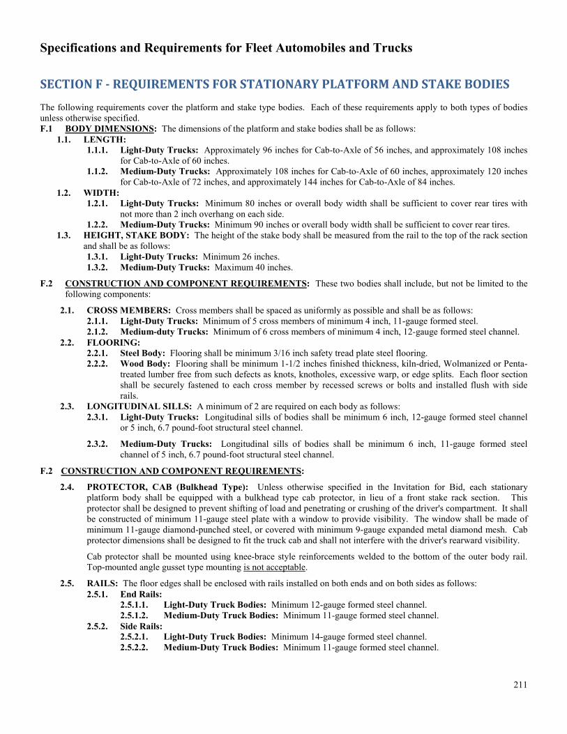
Specifications and Requirements for Fleet Automobiles and Trucks
211
SECTION F - REQUIREMENTS FOR STATIONARY PLATFORM AND STAKE BODIES
The following requirements cover the platform and stake type bodies. Each of these requirements apply to both types of bodies unless otherwise specified. F.1 BODY DIMENSIONS: The dimensions of the platform and stake bodies shall be as follows:
1.1. LENGTH:1.1.1. Light-Duty Trucks: Approximately 96 inches for Cab-to-Axle of 56 inches, and approximately 108 inches
for Cab-to-Axle of 60 inches. 1.1.2. Medium-Duty Trucks: Approximately 108 inches for Cab-to-Axle of 60 inches, approximately 120 inches
for Cab-to-Axle of 72 inches, and approximately 144 inches for Cab-to-Axle of 84 inches. 1.2. WIDTH:
1.2.1. Light-Duty Trucks: Minimum 80 inches or overall body width shall be sufficient to cover rear tires with not more than 2 inch overhang on each side.
1.2.2. Medium-Duty Trucks: Minimum 90 inches or overall body width shall be sufficient to cover rear tires. 1.3. HEIGHT, STAKE BODY: The height of the stake body shall be measured from the rail to the top of the rack section
and shall be as follows: 1.3.1. Light-Duty Trucks: Minimum 26 inches. 1.3.2. Medium-Duty Trucks: Maximum 40 inches.
F.2 CONSTRUCTION AND COMPONENT REQUIREMENTS: These two bodies shall include, but not be limited to thefollowing components:
2.1. CROSS MEMBERS: Cross members shall be spaced as uniformly as possible and shall be as follows: 2.1.1. Light-Duty Trucks: Minimum of 5 cross members of minimum 4 inch, 11-gauge formed steel. 2.1.2. Medium-duty Trucks: Minimum of 6 cross members of minimum 4 inch, 12-gauge formed steel channel.
2.2. FLOORING: 2.2.1. Steel Body: Flooring shall be minimum 3/16 inch safety tread plate steel flooring. 2.2.2. Wood Body: Flooring shall be minimum 1-1/2 inches finished thickness, kiln-dried, Wolmanized or Penta-
treated lumber free from such defects as knots, knotholes, excessive warp, or edge splits. Each floor section shall be securely fastened to each cross member by recessed screws or bolts and installed flush with side rails.
2.3. LONGITUDINAL SILLS: A minimum of 2 are required on each body as follows: 2.3.1. Light-Duty Trucks: Longitudinal sills of bodies shall be minimum 6 inch, 12-gauge formed steel channel
or 5 inch, 6.7 pound-foot structural steel channel.
2.3.2. Medium-Duty Trucks: Longitudinal sills of bodies shall be minimum 6 inch, 11-gauge formed steel channel of 5 inch, 6.7 pound-foot structural steel channel.
F.2 CONSTRUCTION AND COMPONENT REQUIREMENTS:
2.4. PROTECTOR, CAB (Bulkhead Type): Unless otherwise specified in the Invitation for Bid, each stationary platform body shall be equipped with a bulkhead type cab protector, in lieu of a front stake rack section. This protector shall be designed to prevent shifting of load and penetrating or crushing of the driver's compartment. It shall be constructed of minimum 11-gauge steel plate with a window to provide visibility. The window shall be made of minimum 11-gauge diamond-punched steel, or covered with minimum 9-gauge expanded metal diamond mesh. Cab protector dimensions shall be designed to fit the truck cab and shall not interfere with the driver's rearward visibility.
Cab protector shall be mounted using knee-brace style reinforcements welded to the bottom of the outer body rail. Top-mounted angle gusset type mounting is not acceptable.
2.5. RAILS: The floor edges shall be enclosed with rails installed on both ends and on both sides as follows: 2.5.1. End Rails:
2.5.1.1. Light-Duty Truck Bodies: Minimum 12-gauge formed steel channel. 2.5.1.2. Medium-Duty Truck Bodies: Minimum 11-gauge formed steel channel.
2.5.2. Side Rails: 2.5.2.1. Light-Duty Truck Bodies: Minimum 14-gauge formed steel channel. 2.5.2.2. Medium-Duty Truck Bodies: Minimum 11-gauge formed steel channel.

Specifications and Requirements for Fleet Automobiles and Trucks
212
2.6. STAKE RACK SECTIONS: Each stake body shall have stake rack sections with horizontal slats having a maximum 7 inch gap between them. Each stake rack section shall be equipped with the necessary hardware to lock each section to adjacent sections. The slats shall be constructed of either minimum 0.75 inch thick Wolmanized or Penta-treated lumber free of warps, splits, or knotholes; or they may be made from minimum 16-gauge or minimum 18-gauge corrugated steel with rounded corners and smooth edges unless a preference is specified on the Invitation forBids (See Note at the end of Section G.). Each slat shall be securely fastened to 2 steel stakes. The number of slatsper section and the number of stake rack sections per body for the two body sizes shall be as follows:
2.6.1. 108 inch Bodies: 108 inch bodies shall have 2 sections on each side and 2 at the rear. The number of slats per section for the two materials shall be as follows: 2.6.1.1. Lumber or 16-gauge Corrugated Steel: Minimum 3 slats per section. 2.6.1.2. 18-gauge Corrugated Steel: Minimum 4 slats per section.
2.6.2. 144 inch Bodies: 144 inch bodies shall have 3 sections on each side and 2 at the rear. The number of slats per section for the two materials shall be as follows: 2.6.2.1. Lumber or 16-gauge Corrugated Steel: Minimum 4 slats per section. 2.6.2.2. 18-gauge Corrugated Steel: Minimum 5 slats per section.
2.7. STAKE AND STAKE POCKETS: Stakes shall be steel and shall be designed to fit snugly and rigidly inside the stake pockets. Readily accessible lock-down mechanisms are required. The number of stake pockets required for the rear and side rails of the two body lengths are as follows: 2.7.1. 108 inch Bodies:
2.7.1.1. Rear Rail: Minimum 4 stake pockets. 2.7.1.2. Side Rails: Minimum 4 stake pockets on each side.
2.7.2. 144 inch Bodies: 2.7.2.1. Rear Rail: Minimum 4 stake pockets. 2.7.2.2. Side Rails: Minimum 6 stake pockets on each side.
F.3 INSTALLATION AND MOUNTING: The installation and mounting shall be in accordance with the body and vehiclemanufacturer's instructions except for the requirements in Paragraphs A.4.4. through A.4.9.
3.1. LAMPS, REFLECTORS, AND SIDE MARKER LAMPS: Lamps, reflectors, and side marker lamps shall be furnished as required by Paragraphs A.4.8. and A.4.9., General Information and Requirements.
3.2. Mud flaps shall be furnished as required by Section C.8.a.3. F.4 PAINTING:
4.1. STATIONARY BODIES (including Stake Rack Sections): Requirements for stationary bodies (including stake rack sections) are the same as those for dump bodies, Section F.5., except the color shall be the manufacturer's standard unless the Invitation for Bid specified another color.
4.2. PAINTING, TEXAS DEPARTMENT OF TRANSPORTATION (TxDOT): Complete units for TxDOT shall be painted as follows:
4.2.1. Colors, Major Components: The body shall be painted the same color as the truck chassis (cab) except for rubber and those metallic accessories or fixtures constructed of rust-resistant or plated material that are not normally painted. Lead-free paint is acceptable if it matches the color of the truck chassis (cab).
Note to Customer
CUSTOMER SHOULD TAKE SPECIAL NOTE THAT THIS SPECIFICATION REQUIRES WOLMANIZED OR PENTA-TREATED LUMBER OR CORRUGATED STEEL STAKE RACKS FOR STAKE BODIES AT THE OPTION OF THE MANUFACTURER.
REFER TO PARAGRAPH G.2.5., IF THE CUSTOMER HAS A PREFERENCE FOR EITHER WOLMANIZED OR PENTA-TREATED LUMBER OR STEEL (OR HARDWOOD)
SECTION G - REQUIREMENTS FOR UTILITY BODIES
Utility bodies for light-duty trucks, Series 870, 875, 881, 886, and 888 (Option No. 163) and medium-duty trucks, Series 930 through 961 (Option No. 169), shall be general purpose type bodies which meet or exceed the following requirements:

Specifications and Requirements for Fleet Automobiles and Trucks
213
G.1 GENERAL REQUIREMENTS: Each utility body shall be provided with the following, regardless of whether it ismounted on a light-duty or a medium-duty truck: Overall mounted height of the utility body shall provide the lowest profile possible. Body shall not extend more than 4 inches above the bottom of the vehicle's rear window.
1.1. BUMPER, REAR: The rear bumper shall be made of heavy-duty safety tread plate steel with recessed type hitch plate for installation of a ball-type hitch.
1.2. COMPARTMENT DOORS: Each compartment shall have a door and the doors shall have automotive type neoprene weather stripping installed between the door and the compartment so as to make the compartment dust-proof and waterproof.
1.3. HORIZONTAL AND VERTICAL STORAGE SPACE: The Vertical storage compartments shall extend the full height of the utility body on both sides and shall include internal partitions or shelves for storage on parts, tools or equipment. The horizontal compartment shall be located in between the vertical compartments, over the wheel wells and shall include internal partitions or shelves for storage of parts, tools or equipment.
1.4. RECESSED LATCHES: Each compartment door shall have a recessed latch and handle. The handle shall be a lifetime guarantee stainless steel.
1.5. LOCKS: Compartments shall have locks on each door and every lock shall be keyed alike. 1.6. MATERIAL, BODY: Body shall be constructed of minimum 14-gauge automotive type cold- rolled or Galvan Neal
steel. Compartment doors shall be constructed of minimum 16-gauge steel, where furnished as a single panel. Where doors are furnished in a double panel configuration, each panel shall be constructed of minimum 20-gauge steel.
1.7. UNDERCOATING: The entire exposed underside of the utility body shall be completely and thoroughly undercoated without skips, voids, or thin places with a high quality asphalt base underbody coating conforming to Federal Specification TT-C-520B, such as R-477-139 manufactured by Daubert Chemical Co., Chicago, Illinois 60638, or Lion Nokorode Emulsion 331 manufactured by Lion Oil Company, El Dorado, Arkansas 71730, or an Customer Approved Equal. The undercoating shall be applied in accordance with the undercoating manufacturer's instructions.
G.2 OPTIONAL REQUIREMENTS: When so specified in the Invitation for Bid, utility bodies shall be equipped with one ormore of the following options:
2.1. TELESCOPING TOP WITH TAILGATE ENCLOSURE (OPTIONS 164 AND 170): A minimum two-piece top shall be installed as near flush as practicable with the tops of the side compartments. The top shall be complete with a folding and locking tailgate enclosure and/or a heightened tailgate to form a secure and weather-tight storage compartment. The lock shall be keyed alike with compartment door locks. The rear half shall slide forward to provide access to the rear of the body floor.
2.2. TOP OPENING SMALL PARTS TRAY (OPTIONS 165 AND 171): The top of the body shall be hinged to provide access to a full length parts bin with dividers set on approximately 5 inch centers. Bin shall be provided on both compartment sides. Devices(s) shall be provided to hold the lid in the open position.
2.3. THROUGH-COMPARTMENT WITH REAR ACCESS DOOR (OPTIONS 166 AND 172): A full width and length shelf shall extend through all compartments on the curb (passenger) side of the utility body. An access door with handle and lock keyed in common with those provided on the other compartments shall be provided at the rear of the body. The access door shall be aligned with the shelf.
G.3 DIMENSIONS: The approximate dimensions of these utility bodies shall be as follows:
3.1. LIGHT-DUTY TRUCKS (Series 870, 875, 881, 886, and 888):
Parameter Series Number
870 875 881 886 888
Width, Cargo Body, inches 51 49-54 51 54 54
Length, inches 96 108 96 96 96
Compartment Depth, inches 14-1/2 20 14-1/2 20 20
Utility Body Height, inches 36 36 36 36 36
Utility Body Overall Width, inches 80 94 80 94 94
NOTE: WIDTH BETWEEN WHEEL WELLS OF PICKUP CAB AND CHASSIS UNITS (SERIES 881 AND 886) WITH DUAL REAR WHEELS IS APPROXIMATELY 42 INCHES.

Specifications and Requirements for Fleet Automobiles and Trucks
214
3.2. MEDIUM-DUTY TRUCKS (Series 930 through 961): Cab-to-Axle Dimensions 60 inches 84 inches
Width, Cargo Body, inches 49-54 * 49-54 *
Length, inches 108 132
Compartment Depth, inches 20 18”-20”
Utility Body Height, inches 36 36”-40”
Utility Body Overall Width, inches 89-94 * 89-94 *
* Applicable for Series 930 only (See NOTE (following) referring to maximum overhang).
NOTE: BODY WIDTH SHALL BE SUFFICIENT TO ADEQUATELY COVER REAR TIRES WITH NO MORE THAN 2 INCH OVERHANG ON EACH SIDE. BODY SHALL BE PROPER SIZE FOR CHASSIS.
G.4 PAINTING:
4.1. REQUIREMENTS: Painting requirements for utility bodies are the same as those for dump bodies, Section F.5.
4.2. Color, Major Components: The utility body shall be painted the same color as the truck chassis (cab) except for rubber or those metallic accessories or fixtures constructed of rust-resistant or plated material that are not normally painted.
SECTION H – SPECIAL EQUIPMENT – PARA-TRANSIT BODY & WHEELCHAIR LIFT 1. GENERAL DESCRIPTION
The purpose of these specifications is to describe the conversion of a full size van or a cutaway chassis asmanufactured by the vehicle OEM, equipped with a raised roof, wheelchair lift, provisions for stand-up entry andwheelchair passenger securement. Conversion must meet the requirements of the Americans with Disabilities Act,including but not limited to the provisions of the wheelchair lift, wheelchair entry and securement.
Unless otherwise specified, all units shall be furnished complete with standard equipment and factory-installedaccessories as listed in the manufacturer's literature for the models specified herein. The following items areminimum requirements and shall be provided whether shown as optional or standard equipment by themanufacturer.
1.1
1.2
All Standard and Common Features Shall be Furnished Standard and common features, some related to safety and others to driver and passenger convenience, which are generally provided in a para-transit vehicle without customer stipulation. Those features include but are not limited to: adjustable instrument lights, interior sun visors, exterior backup lamps, two-speed windshield wipers, windshield washers, windshield defroster, coolant recovery system, etc. Standard and other common features if not specifically stated shall not be interpreted as items that can be omitted to reduce price or to provide any other bidding advantage. Certification of ISO 9001:2000 Compliance The manufacturer of the vehicles shall have a proven, third-party certified quality control system in place and shall be ISO 9001:2000 certified at the facility that will produce the vehicles.
2. GENERAL DIMENSIONSWheelbase.....................................................… 138" min. Interior height from floor to ceiling..................... 72" min. Interior height from floor to ceiling at aisle......... 75" min. Height at first step.............................................. 12" max. Height at passenger door entrance.................... 78" min. Aisle width.......................................................... 14" min.

Specifications and Requirements for Fleet Automobiles and Trucks
215
Interior width at floor level.................................. 76" min. Gross Vehicle Weight Rating............................. 9,250 lbs. min. 3. BUMPERS
Chassis manufacturer's standard front chrome bumper and vehicle manufactured standard rear bumper. Rear bumper to be of sufficient strength to allow the vehicle to be pushed without damage.
4. ELECTRICAL 4.1 A minimum of 200 ampere alternators shall be provided. 4.2 Chassis manufacturer supplied batteries shall be mounted on a stainless steel roller mounted pull out tray with
battery hold down secured with bolts. Inside of compartment should be covered with a durable insulating material to prevent shorts. Battery compartment should be vented and the battery shall be easily serviceable without removal from battery tray.
4.3 All wiring other than that provided with the OEM chassis shall be number and function coded every 6 inches and shall be color coded. The body manufacturer shall furnish a complete wiring diagram with integrated body and chassis marked to show the codes used.
4.4 Fast idle solenoid with manual switch, volt sensor and light shall be installed. Solenoid is to automatically shut off when transmission is in gear or brake is applied.
5. LIGHTING
5.1 Overhead entrance and stepwell lights shall provide no less than five foot-candles of illumination on the entrance step area with the door open. This system shall be illuminated automatically when the door is open. Overhead and stepwell lights shall be wired to and activated automatically by door control and by a separate dash mounted switch.5.2 All exterior lights, with the exception of headlights, passenger entry door, lift door, curb light, and rear back-up lights shall be Light Emitting Diode (LED) lights. Lighting shall be in accordance with Federal Motor Carrier Safety Regulations 393.12. All lights shall have wire long enough to move the light at least six inches (6") from vehicle for service. Lights shall be grounded to body framing structure. All lights shall be sealed from moisture. Marker lights shall be armored, surface mounted. Center brake light shall be furnished.
6. AIR CONDITIONING 6.1 Air Conditioning Performance Specifications
The installed air conditioning system shall cool the interior of the vehicle to 80F measured at a minimum of three points, located four feet above the floor at the longitudinal centerline of the vehicle. The three points shall be (1) near the driver's location; (2) at the mid-point of the body; and (3) two feet forward of the rear of the vehicle
6.2 Compressors A chassis OEM supplied compressor and an engine mounted TM-16 compressor each rated @ 52,000-btu/hr (imaca) shall be provided. Each unit shall have a nominal ten (10) cubic-inch displacement, and is to be belt driven off of the vehicle's engine. The compressors are to be equipped with an electro-magnetic clutch controlling each of the system's (2) thermostats.
6.3 Condenser Condenser shall be a under floor skirt mounted unit rated @ 76,000 btu/hr (imaca). This unit shall be capable of producing a total of 2,400 cfm of airflow (rated @ 13.5vdc / 0" static). This unit shall contain three (3) single speed permanent magnet four pole, four brush 10,000 hour design life sealed ball bearing motors. This unit's maximum amperage draw shall be 21 amps @ 13.5vdc. The unit's refrigerant connections shall be of a corrosion resistant brass, and shall be of the o-ring type to insure leak-free continuous operation. The unit's filter drier shall be a minimum sixteen (16) cubic inches of desiccant compatible with R-134A; equipped with o-ring connections to insure leak-free connections, and capable of maintaining a dry, non-acidic system.
6.4 Evaporators Evaporators shall be a chassis OEM supplied 15,000 btu/hr drivers in dash air conditioning unit and a rear center ceiling mounted unit rated @ 52,000 btu/hr (imaca). This rear unit shall be capable of producing 1,600 cfm of airflow on high speed (rated @ 13.5vdc/0" static). This unit shall contain two (2) three speed permanent magnet 10,000 hour design life sealed ball bearing motors. This unit's maximum amperage draw shall be 36 amps @ 13.5 vdc. The unit shall be equipped with an easily removable, cleanable filter element capable of filtering air to 10,000 ppm. The unit's expansion valve shall be equipped with o-ring fittings to insure leak-free continuous operation.

Specifications and Requirements for Fleet Automobiles and Trucks
216
6.5 Controls The vehicle's air conditioning system shall be controlled from the driver's seated position. The controls shall consist of (2) rotary fan speed switch (off/high/medium/low), and (2) rotary or slide type thermostat switches.
7. HEATING AND DEFROSTING
A rear hot water heater with blower fan shall have a BTU rating of at least thirty thousand (30,000) shall be installed under a seat near the rear of the vehicle. The controls shall be readily accessible to the driver. Heater hose connections shall be installed above the floor of the vehicle body and through: he fire wall to the engine compartment. Easily accessible all brass gate valve(s) shall be furnished to cut off the flow of coolant water to the rear heater.
8. SAFETY EQUIPMENT
8.1 First Aid Kit; Will be the standard State of Texas School Bus First Aid Kit. Kit shall be securely mounted near the driver's seat (Description of School Bus First Aid Kit can be located at the following link: http://www.dps.texas.gov/schoolbus/sbtexspecs.htm
8.2 Fire Extinguisher; One 5-pound dry type (BC rated), securely mounted near the driver's seat. 8.3 Reflectors; Three folding triangle reflectors with storage container(s). 8.4 Back up Alarm; Meeting the requirements of SAE J994B or the latest revision thereto. 8.5 Fresnel Lens; provided on the rear window of the vehicle.
9. MIRRORS
9.1 Exterior; Rearview mirror, manufacturer's exterior low mount type with extension arms (below eye level) wide view type mirror. Mirror shall be a minimum of 6 inches by 9 inches. Additionally minimum 5-inch convex mirrors to be mounted with brackets on top of the main mirrors on the left and right sides.
9.2 Interior; Day/night type, conforming to FMVSS No. 111 and affording a good view of the road to the rear as well as the passenger area. The mirror(s) shall be made of safety glass, having rounded corners and protective edges. If more than one interior mirror is installed, at least one of the mirrors shall have a minimum of 90 square inch of clear vision, reflective surface area.
9.3 Passenger Mirror; an additional minimum 6-inch by 10-inch interior mirror shall be furnished for the driver to view the passengers.
10. WINDOWS
Side windows to be provided for the full length of the vehicle. If the windows are transit type T-slider windows they shall be equipped with emergency release latches to provide emergency exits. Release instructions shall be provided at or near the release handles and an audible alarm shall be activated when any handle is released. Side windows, rear window(s) and glass in passenger entrance door shall be of uniform dark tint sufficient to permit no more than 31% light transmission. Tinted film is not acceptable.
11. PASSENGER SEATS
All frames shall be high quality heavy duty tube; jig welded, and utilizing a heavy duty wire mesh grid for seat support. The back rest shall have steel straps for back support. Standard seat cushion width shall be 17 1/2" (single) or 35" (double). Back cushion height shall be 22 1/2" from the top of the seat cushion and 36 13/16” from the top of the back cushion to the floor. Cushions shall be molded polyurethane to ensure maximum individual passenger comfort and durability. All seats shall provide lower lumbar and side bolster support. Upholstery shall be level 1 material and select by the agency. Seats shall be recessed track mounted with pedestal support legs and hardware. Seat tracks shall be welded to the body structure and shall not rely on screws alone. Floor anchorage shall be neat and of a non-tripable design. Seating and securement shall meet or exceed every applicable Federal Motor Vehicle Safety Standard. 11.1 Seat backs shall be high impact ABS material which is recessed to provide one and one half inches (1-1/2") of
additional passenger hip to knee room. 11.2 A retractable seatbelt shall be provided for each seated passenger. The retractor shall be emergency locking with
anti-cinch capability. The retractor must be attached to the seat structure. Passenger Seatbelts shall be “A” type one seat belt assembly conforming to current FMVSS 209 requirements.
11.3 Aisle seats shall include an energy absorbent grab bar three quarter inch (3/4"), twenty (20) gauge steel covered with custom molded, wear and vandal resistant eight (8) pound density, self-skinning polyurethane foam. Grab bar shall be located in the top of the seatback.
12. BODY CONSTRUCTION

Specifications and Requirements for Fleet Automobiles and Trucks
217
Sides and roof shall be constructed of metal or fiberglass panels. Roof shall be of sufficient height to provide at least 75 inches headroom at the center aisle. Headroom may be reduced slightly in some areas of the vehicle to accommodate other specified equipment such as air conditioner components and the normal contour of the roof. The structure shall be watertight and shall meet the requirements of Federal Safety Standards as to school bus rollover protection, No. 220. Bus body consisting of steel cage construction with polystyrene insulation (or equal in performance) and exterior skin of galvanized steel, aluminum or FRP (fiberglass reinforced plastic). Side walls must be bonded together using the lamination process. Adhering sidewall skin to steel cage with double sided tape or any method other than lamination will not be accepted. A bus body consisting of a matrix of honeycomb composite material with steel reinforcement will not be accepted.
13. ROOF LINER The roof liner shall be of molded fiberglass installed the full length so as to cover all protrusions. 14. PASSENGER ENTRANCE DOOR AND STEPS
Passenger entrance door shall be a transit type, and shall have a minimum horizontal opening of approximately 24 inches and a minimum vertical opening of approximately 78 inches. The door shall be operated from controls at or near the vehicle driver's seated position. The door shall be manually operated, and shall be designed to allow manual opening in case of an emergency. The steps shall be designed so that the top of the first step is no more than 12 inches above the ground with the vehicle unloaded. Steps of at least 24 inches in width, approximately eight (8) inches deep and a maximum riser of 10-1/2 inches shall be fabricated and installed inside of the body to meet this requirement. The surface of all entrance steps shall have a non-skid material applied. A two inch white safety nosing shall be placed on each step edge.
15. STANCHIONS, GRAB RAILS, AND MODESTY PANELS Vertical stanchions shall be provided at the aisle immediately behind the driver's seat and the stepwell; a horizontal grab rail shall extend from the wall to each stanchion. A modesty panel shall be attached to the stanchion behind the stepwell. 15.1 A smoked three eights inch (3/8") thick panel Plexiglas panel shall be provided behind the driver’s seat. Panels
shall extend from the top of the horizontal grab rail to the ceiling and shall extend from the wall to the vertical stanchion. Stanchion and panel shall not impair driver's seat adjustment
15.2 An overhead handrail shall be installed in the roof of the vehicle on the driver and curb side and shall run the length of the seating area.
16. WHEELCHAIR LIFT DOOR Side opening double outward opening doors shall be provided for the platform type wheelchair lift. Lift shall be mounted
within the vehicle body on the curb side. The wheelchair doorframe structure shall consist of a minimum 12-gauge steel Door panel hinges shall be piano type with a minimum three sixteenth (3/16") inch diameter pivot pin. Each door panel shall have its own key lockable latch assembly which shall consist of a pistol grip style twist handle located at the inside center of the door panel. Door panel holders shall be gas shock type mounted at the top and shall allow door panels to open a minimum of one hundred degrees (100º) from the closed position. Wheelchair door clear opening dimensions shall be a minimum of forty (40") inches by sixty seven (67") inches. Lift doors shall be interlocked by a panel door switch controlling the transmission which requires the transmission to be in the "Park" position before lift can be operated. Door windows shall be installed with two (2) piece black ozone treated extruded rubber, lock and key of one (1) piece fixed design.
17. WHEELCHAIR LIFT 17.1 The wheelchair lift shall comply with all Federal ADA requirements.
17.2 The wheelchair lift shall be a fully automatic, including folding of platform and be electro-hydraulically powered with a minimum test-net load capacity of eight hundred (800) pounds. The lift shall be totally self-contained and installed without modifications to the vehicle body or frame inside of the curbside double service doors. The entire assembly shall be installed with adequate protection to prevent accidental injury to passengers.
17.3 The complete wheelchair lift assembly shall operate from the vehicle's electrical system, and shall have one hand-held lift control station with a minimum five foot (5') cable attached so lift may be operated from inside or outside of vehicle.
18. WHEELCHAIR SECUREMENT AND SEATBELTS 18.1 The vehicle shall have forward facing wheelchair positions. Each wheelchair position shall be provided with
restraint devices that will secure the wheelchair and its passenger while in the wheelchair. These devices shall be adjustable to accommodate varying track widths of wheelchairs. Each wheelchair shall have a four (4) point securement (2 front, 2 back) in the vehicle with recessed anchor points of sufficient strength to secure a wheelchair and/or three wheel scooter. The entire securement system shall comply with all applicable regulations including ADA.

Specifications and Requirements for Fleet Automobiles and Trucks
218
18.2 Floor mounted tracks shall be a series type "L” track floor plate. These plates shall be recessed mounted in the floor with three-eighths inch (3/8") diameter, SAE Grade 5 bolts, washers and self-locking nuts with National Fine Threads.
18.3 There shall be four (4) retractors assemblies for each wheelchair position in the vehicle to secure the wheelchair to the tracks. Example: Q’ Strain QRT Deluxe (Q-8100-A1) System, or approved equal. Each retractor assembly shall consist of a heavy duty series “L” track fitting, the front left and right retractor shall be equipped with manual tension knobs for manual tightening and/or release. Each retractor assembly shall be equipped with a quick release, push-button buckle and buckle connector.
18.4 Two (2) seat belts shall be provided for each wheelchair passenger. The torso belts shall be two inches (2") wide, seventy-two inches (72") long, adjustable, with a strength rating of not less than three thousand pounds (3,000 lbs.). One end of the belt shall be secured to a female seat belt fitting and the other end shall have a male seat belt fitting. The seat belt assembly shall provide for a quick-release and also provide for a snap locking to connect both ends together.
18.5 A wall mounted height adjustable of approximately twelve inches (12") shoulder harness system shall be provided at each wheelchair securement location that is compatible with the specified restraints. The harness system shall be installed in accordance with all structural requirements established by the restraint supplier and all applicable regulations, including 49 CFR part 571.
18.6 All belts, straps, and harness assemblies in bundled sets and shall include a container in which to store them. Storage compartments shall be provided over the windshield and over the driver’s door.
19. EMERGENCY EXITA combination roof ventilator and emergency escape hatch shall be provided towards the rear of the vehicle. A rear duty emergency door shall be provided at the rear of the vehicle.
20. FLOOR AND FLOOR COVERINGThe vehicle floor assembly shall be a minimum five eighths of an inch (5/8"), seven (7) ply, exterior grade plywood which is pattern cut, edge sealed, and attached with quarter inch (1/4") diameter counter sunk Tek screws. The floor in the under-seat area shall be covered with smooth gray rubber floor covering having a minimum thickness of .125 inch (1/8"). Floor covering in aisle and on steps shall be non-skid, wear-resistant, and ribbed. Minimum overall thickness shall be .1875 inch (3/16") measured from top of ribs.
21. PAINTINGExterior surfaces normally painted shall be thoroughly degreased, primed, and painted solid white. The base vehicle shall be Bright White in color. The area around the passenger windows shall be black.
22. DELIVERYAll vehicles must be serviced prior to delivery in accordance with the manufacturer's "New Vehicle Pre-delivery Service" requirements and with Part II, Paragraphs 3.3 and 3.4 of this specification.
23. REGISTRATIONContractor shall provide necessary documents to enable the purchasing agency to register the vehicle in the State of Texas. Necessary fees and state taxes will be paid by the purchasing agency.
24. MANUALSA line setting sheet and manual(s) containing operating and servicing instructions for the vehicle shall be provided with each unit. The manual(s) shall be as detailed as possible outlining all necessary operating and servicing instructions for each vehicle including the vehicle's driveline components. Necessary warnings and safety precautions shall be included. In addition, manual(s) containing illustrated parts lists, operating and servicing instructions for related and special equipment supplied with the vehicle shall be provided with the unit.
25. WARRANTYThe vehicle shall be warranted against defects in material and workmanship for a period of not less than 12 months or 12,000 miles, whichever comes first and shall cover 100 percent parts and labor for the unit. If the manufacturer's standard warranty exceeds 12 months then the standard warranty period shall be in effect. Contractor shall furnish manufacturer's warranty to the receiving agency at time of delivery. The Contractor is ultimately responsible for the warranty. EXCLUSIONS: The using agency will assume the expense for replacement filters, fuel, cleaning, painting and other minor items normally consumed in day to day operations. The using agency will assume responsibility for cost of repairs resulting from collision, theft, vandalism, operator negligence and/or acts of God.
26. PARTS AND SERVICEThe manufacturer of the vehicle furnished shall have an authorized dealer within the State of Texas. The authorized

Specifications and Requirements for Fleet Automobiles and Trucks
219
dealer shall have factory-trained personnel available for warranty repairs and the performance of service. The dealer shall also maintain an inventory of high-usage parts and a quick source for low-usage parts. If the manufacturer offers a complimentary service contract with the purchase of a new vehicle, that service contract shall be included with all vehicles purchased under these contracts (071-072-A1).
27. SAFETY DECAL(S)Safety decal(s) shall be furnished and shall be affixed at any applicable area (emergency exit, steps, etc.). The decals shall include necessary warnings and precautions. Permanent decals (plaques) are preferred.
28. INSTRUCTION ON SAFETY, OPERATION AND PREVENTIVE MAINTENANCEThe Contractor shall provide the agency sufficient instruction on safety, operation and preventivemaintenance of the vehicle after the unit has been delivered and is ready for operation but prior to payment.
SECTION I –SPECIAL EQUIPMENT–PARA-TRANSIT LOW-FLOOR BODY & WHEELCHAIR RAMP 1. GENERAL DESCRIPTIONThe purpose of these specifications is to describe the conversion of a steel cage, low floor, commercial bus designed foruse in Shuttle and Transit applications that meets all the requirements of ADA and the FMVSS Safety Standards in effectat the time of manufacture.
The proposed bus must have been tested at the Federal Bus Testing Center at Altoona, PA in the 7-year/ 200,000 mile category. The bus must meet all the chassis specifications listed in the chassis section.
The bus will be of a “Steel Cage” type construction with FRP Composite Skin laminated to a moisture resistant (less than 1%) substrate (not Luan) attached to the steel cage with urethane adhesive. The roof will consist of a single piece FRP skin laminated to the substrate and roof steel with urethane adhesive. The bus body is constructed of welded walls, sub floor, roof framing, and rear steel structure which are bonded and bolted together, forming an integrated steel cage around the passenger area.
Unless otherwise specified, all units shall be furnished complete with standard equipment and factory-installed accessories as listed in the manufacturer's literature for the models specified herein. The following items are minimum requirements and shall be provided whether shown as optional or standard equipment by the manufacturer.

220
1.1 All Standard and Common Features Shall be Furnished
1.2
1.3
Standard and common features, some related to safety and others to driver and passenger convenience, which are generally provided in a para-transit vehicle without customer stipulation. Those features include but are not limited to: adjustable instrument lights, interior sun visors, exterior backup lamps, two-speed windshield wipers, windshield washers, windshield defroster, coolant recovery system, etc. Standard and other common features if not specifically stated shall not be interpreted as items that can be omitted to reduce price or to provide any other bidding advantage.
Certification of ISO 9001:2000 Compliance The manufacturer of the vehicles shall have a proven, third-party certified quality control system in place and shall be ISO 9001:2000 certified at the facility that will produce the vehicles.
All Standard and Common Features Shall be Furnished Standard and common features, some related to safety and others to driver and passenger convenience, which are generally provided in a para-transit vehicle without customer stipulation. Those features include but are not limited to: adjustable instrument lights, interior sun visors, exterior backup lamps, two-speed windshield wipers, windshield washers, windshield defroster, coolant recovery system, etc. Standard and other common features if not specifically stated shall not be interpreted as items that can be omitted to reduce price or to provide any other bidding advantage.
2. GENERAL DIMENSIONSWheelbase.....................................................165" min. Interior height from floor to ceiling front.............. 86" min. Interior height from floor to ceiling at rear......... 76" min. Height at first step.at ride height................... 14.5" max. Height at first step.at ride height- bus knelt... 10.5" max.
Height at passenger door entrance............... .... 75" min. Aisle width.......................................................... 14" min. Interior width at floor level.................................. 91" min.
Exterior width ......................................... 96" max Gross Vehicle Weight Rating.................... 14,200 lbs. min.
Axles and Suspension 2.1 Front axle capacity 4,600 #GAWR for 14,200 GVW vehicles. All chassis’ will be equipped
with air spring suspension including all electric air compressor. This air system shall be managed by an electronically controlled manifold that will control the height of the suspension. Note: SYNC –SYNCHRONIZED AIR-RIDE SUSPENSION SYSTEM WILL NOT BE ACCEPTED.
2.2 Heavy Duty Air Dryer required. Must be able handle 80% air compressor duty cycle. Midland Pure Air Dryer or approved equal
2.3 Wheel cut 45 degrees. 2.4 OEM DANA HD70 Rear Axle for 14,200 GVWR or UltraRide suspension by Link MFG (or
Approved Equal) 2.5 Constant Ride Height Control with Three Electronic Height Sensors. 2.6 Front/Rear Air Suspension with Kneeling feature. (4” Kneel from Ride Height, 10.0” from
ground, 4.0” to Curb. 2.7 Front tires must be completely vertical at all times. Vehicle must be able to be moved in full
kneeling position in case of air ride failure. Rear Air Spring Suspension with ARBOC® 4-Bar linkage and Track Bar. Constant Ride Height Control with Three Electronic Height Sensors.
2.9 Front/Rear Electric Compressor Air Suspension with Kneeling feature. (3” Kneel from Ride Height, 10.25” from ground, 4.25” to Curb)
3. BUMPERSChassis manufacturer's standard front chrome bumper and vehicle manufactured standard rear bumper.Rear bumper must be of sufficient strength to allow the vehicle to be pushed without damage.

Specifications and Requirements for Fleet Automobiles and Trucks
221
4. ELECTRICAL4.1 Electrical box for the bus body shall be located inside above the driver in a compartment with a door. Fuse,
relay and component location will be labeled on the inside of this door. 4.2 Automotive type fuses are required. 4.3 Wiring needs to be color coded, and labeled for function every 12” and meet all the requirements of the
Society of Automotive Engineers (SAE Standards). 4.4 All body component circuits shall be protected in convoluted split loom tubing for protection and
tied/anchored a minimum every 16”. 4.5 The bus will be equipped and labeled with extra fuse protected circuits for the use of the customer
(minimum of 4 extra circuits). Fuses to be located in electrical box described in section 15.1 all exterior loomed wire harnesses shall have waterproof connectors and sprayed with corrosion resistance spray.
4.6 Rotary disconnect switch located near the driver. 4.7 Pre-wired for 2 way radio with a minimum 6”X6” metal ground plane for the antenna. Wiring for radio will
be designed for center console mounting. 4.8 A wiring diagram, “As Built” is required. The wiring diagram should indicate schematics and wire color,
gauge, and location. There should be separate diagrams for each system i.e. Doors, heaters, lights etc. A master wiring diagram will also be included of the complete wiring system added to the chassis.
4.9 A minimum of 200 ampere alternators shall be provided. 4.10 Chassis manufacturer supplied batteries shall be mounted on a stainless steel roller mounted pull out tray
with battery hold down secured with bolts. Inside of compartment should be covered with a durable insulating material to prevent shorts. Battery compartment should be vented and the battery shall be easily serviceable without removal from battery tray.
4.11 All wiring other than that provided with the OEM chassis shall be number and function coded every 6 inches and shall be color coded. The body manufacturer shall furnish a complete wiring diagram with integrated body and chassis marked to show the codes used.
4.12 Inter-motive Gateway idle with manual switch, volt sensor and light shall be installed. Solenoid is to automatically shut off when transmission is in gear or brake is applied.
5. LIGHTING5.1 Overhead entrance and step well lights shall be Light Emitting Diode (LED) and provide no less
than five foot-candles of illumination on the entrance step area with the door open. This system shall be illuminated automatically when the door is open. Overhead and step well lights shall be wired to and activated automatically by door control and by a separate dash mounted switch.
5.2 All exterior lights, with the exception of headlights, passenger entry door, lift door, curb light, and rear back-up lights shall be Light Emitting Diode (LED) lights. Lighting shall be in accordance with Federal Motor Carrier Safety Regulations 393.12. All lights shall have wire long enough to move the light at least six inches (6") from vehicle for service. Lights shall be grounded to body framing structure. All lights shall be sealed from moisture. Marker lights shall be armored, surface mounted. Center brake light shall be furnished.
6. AIR CONDITIONING6.1 Air Conditioning Performance Specifications The installed air conditioning system shall be roof
mounted and shall cool the interior of the vehicle to 80F measured at a minimum of three points,located four feet above the floor at the longitudinal centerline of the vehicle. The three points shall be (1) near the driver's location; (2) at the mid-point of the body; and (3) two feet forward of the rear of the vehicle.
6.2 Compressors A chassis OEM supplied compressor and an engine mounted TM-16 or larger compressor each rated @ 52,000-btu/hr (imaca) shall be provided. Each unit shall have a nominal ten (10) cubic-inch displacement, and is to be belt driven off of the vehicle's engine. The compressors are to be equipped with an electro-magnetic clutch controlling each of the system's (2) thermostats.
6.3 Condenser

Specifications and Requirements for Fleet Automobiles and Trucks
222
Condenser shall be a under floor skirt mounted unit rated @ 76,000 btu/hr (imaca). This unit shall be capable of producing a total of 2,400 cfm of airflow (rated @ 13.5vdc / 0" static). This unit shall contain three (3) single speed permanent magnet four pole, four brush 10,000 hour design life sealed ball bearing motors. This unit's maximum amperage draw shall be 21 amps @ 13.5vdc. The unit's refrigerant connections shall be of a corrosion resistant brass, and shall be of the o-ring type to insure leak-free continuous operation. The unit's filter drier shall be a minimum sixteen (16) cubic inches of desiccant compatible with R-134A; equipped with o-ring connections to insure leak-free connections, and capable of maintaining a dry, non-acidic system.
6.4 Evaporators Evaporators shall be a chassis OEM supplied 15,000 btu/hr drivers in dash air conditioning unit and a rear center ceiling mounted unit rated @65,000 btu/hr (imaca). This rear unit shall be capable of producing 1,600 cfm of airflow on high speed (rated @ 13.5vdc/0" static). This unit shall contain two (2) three speed permanent magnet 10,000 hour design life sealed ball bearing motors. This unit's maximum amperage draw shall be 36 amps @ 13.5 vdc. The unit shall be equipped with an easily removable, cleanable filter element capable of filtering air to 10,000 ppm. The unit's expansion valve shall be equipped with o-ring fittings to insure leak-free continuous operation.
6.5 Controls The vehicle's air conditioning system shall be controlled from the driver's seated position. The controls shall consist of (2) rotary fan speed switch (off/high/medium/low), and (2) rotary or slide type thermostat switches.
7. HEATING AND DEFROSTING A rear hot water heater with blower fan shall have a BTU rating of at least thirty thousand (30,000) shall be
installed under a seat near the rear of the vehicle. The controls shall be readily accessible to the driver. Heater hose connections shall be installed above the floor of the vehicle body and through: he fire wall to the engine compartment. Easily accessible all brass gate valve(s) shall be furnished to cut off the flow of coolant water to the rear heater.
8. SAFETY EQUIPMENT
8.1 First Aid Kit; Will be the standard State of Texas School Bus First Aid Kit. Kit shall be securely mounted near the driver's seat.
8.2 Fire Extinguisher; One 5-pound dry type (BC rated), securely mounted near the driver's seat. 8.3 Reflectors; Three folding triangle reflectors with storage container(s). 8.4 Back up Alarm; Meeting the requirements of SAE J994B or the latest revision thereto. 8.5 Fresnel Lens; provided on the rear window of the vehicle.
9. MIRRORS
9.1. Exterior; Rearview mirror, manufacturer's exterior low mount type with extension arms (below eye level) wide view type mirror. Mirror shall be a minimum of 6 inches by 9 inches. Additionally minimum 5-inch convex mirrors to be mounted with brackets on top of the main mirrors on the left and right sides. 9.2. Interior; Day/night type, conforming to FMVSS No. 111 and affording a good view of the road to the rear as well as the passenger area. The mirror(s) shall be made of safety glass, having rounded corners and protective edges. If more than one interior mirror is installed, at least one of the mirrors shall have a minimum of 90 square inch of clear vision, reflective surface area. 9.3. Passenger Mirror; an additional minimum 6-inch by 10-inch interior mirror shall be furnished for the driver to view the passengers. 9.4. OE Compliant mirror (GM and Ford tested for vibrations, door slams, UV testing, Salt spray testing, Thermal testing (temperatures of -40F to 212F) and shell load test (holds 225 lbs. max. load).
10. WINDOWS
10.1 One Double T – Slider window on each side of the bus will be standard. Option of all T slider windows is available.
10.2 Passenger windows shall be a minimum 18 ½”, 36” or 45” wide and 36” high (body length will dictate sizes).
10.3 Egress windows shall be provided in sufficient numbers and labeled to meet FMVSS and state minimum requirements (23 ½” x 60”). A minimum of one on each side and the rear is required.

Specifications and Requirements for Fleet Automobiles and Trucks
223
10.4 Side windows to be provided the full length of the vehicle. If the windows are transit type T-slider windows they shall be equipped with emergency release latches to provide emergency exits. Release instructions shall be provided at or near the release handles and an audible alarm shall be activated when any handle is released. Side windows, rear window(s) and glass in passenger entrance door shall be of uniform dark tint sufficient to permit no more than 31% light transmission. Tinted film is not acceptable.
11. PASSENGER SEATS AND STOP REQUEST
All seating installed in this vehicle shall be in compliance with FMVSS 207 (Seating System) and any associated seat belt assemblies shall be in compliance with FMVSS 209, 210 (Seat Belt Assembly, Seat Belt Assembly Anchorage’s). Testing of the seats must have been performed in the bus. A level 5 fabric must be used. 11.7 Citi Seats w/Inserts 11.8 Single Flip Citi Seats 11.9 Citi Seat Back Grab Rails 11.10 USR Double (Under Seatbelts) 11.11 USR Single (Under Seat Belts) 11.12 Citi Seat Level 4 Inserts 11.13 Minimum Aisle: 18” Standard; (Optional wider seats will decrease aisle width). 11.14 Seating quantity shall be determined by the floor plan selected. 11.15 Stop request system will have a pull cord type activation and a large “Stop Request“ display with
an adjustable audible Chime. The display will need to be easily seen by the passengers and driver or have a second dash light in the driver’s area. Display will be reset to off with the opening of the passenger doors. The system will need a switch to reset false trip of pull cord other than the opening and closing of the doors. Activation strips or pull cords will need to be at an appropriate level for activation by riders in wheelchairs in the para-transit locations.
12. BODY CONSTRUCTION SIDE WALL AND REAR WALL CONSTRUCTION
Sides and roof shall be constructed of fiberglass panels. Roof shall be of sufficient height to provide at least 75 inches headroom at the center aisle. Headroom may be reduced slightly in some areas of the vehicle to accommodate other specified equipment such as air conditioner components and the normal contour of the roof. The structure shall be watertight and shall meet the requirements of Federal Safety Standards as to school bus rollover protection, No. 220, as well as FMVSS 214 Side Impact Protection 12.1 There is one 1 ½” X 1 ½” horizontal 16 gauge steel tube below the window line and one 1 ½” X
2 ½” 14 gauge tube at the floor level, or approved equal. There is one 1 ½” X 1 ½” horizontal 16 gauge steel tube at the top sidewall forming the top edge of the wall, or approved equal Steel structure must extend to or below the floor level to the lowest point in the sidewall, or approved equal.
12.2 Vertical steel 16 gauge square tubing nominal dimensions 1 ½” X 1 ½”. Vertical steel ribs consist of one (1) 1 ½” X 2” 16 gauge steel spaced at the sides of each window opening, or approved equal.
12.3 Two (2) 1½” X 1½” 16 gauge steel tubes are required at the front of the sidewall to form the front & rear of the door opening. One (1) 1 ½” X 1 ½” 16 gauge steel tube is welded vertically at the midpoint of each window with a width greater than 24 inches connecting the horizontal tube welded below the window line and the horizontal tube that is welded at the floor line, or approved equal.
12.4 Horizontal steel tubes are welded to the vertical steel tubes. The entire steel structure must be bonded and bolted together with Sikaflex 252 or Locktite H8600 adhesive and have a full E-Coat corrosion protection to prevent rust/corrosion.
12.5 Exterior skin is FRP composite skin laminated to a moisture resistant (less than 1% absorption) substrate (not Luan) attached to the steel cage with urethane adhesive.
12.6 No wood or Luan is permitted in the sidewalls or rear end wall of the bus. Laminated constructions with Luan or other wood materials are not allowed as they can lead to corrosion of the skin due to the wicking of moisture into the wood material.
12.7 Rear of the bus shall have vacuum formed caps bonded to a FRP Composite Skin laminated to a moisture resistant (less than 1% absorption) substrate (not Luan) attached to the steel cage with

Specifications and Requirements for Fleet Automobiles and Trucks
224
urethane adhesive or a full Fiberglass panel. The LED lights shall be mounted to the vacuum formed or Fiberglas caps.
13. ROOF LINER The roof liner shall be of molded fiberglass installed the full length so as to cover all protrusions. 14. PASSENGER ENTRANCE DOOR AND STEPS
Passenger entrance door shall be a transit type, and shall have a minimum horizontal opening of approximately 24 inches and a minimum vertical opening of approximately 78 inches. The door shall be operated from controls at or near the vehicle driver's seated position. The door shall be manually operated, and shall be designed to allow manual opening in case of an emergency. The steps shall be designed so that the top of the first step is no more than 12 inches above the ground with the vehicle unloaded. Steps of at least 24 inches in width, approximately eight (8) inches deep and a maximum riser of 10-1/2 inches shall be fabricated and installed inside of the body to meet this requirement. The surface of all entrance steps shall have a non-skid material applied. A two inch white safety nosing shall be placed on each step edge.
15. STANCHIONS, GRAB RAILS, AND MODESTY PANELS Vertical stanchions shall be provided at the aisle immediately behind the driver's seat and the stepwell; a horizontal grab rail shall extend from the wall to each stanchion. A modesty panel shall be attached to the stanchion behind the stepwell. 15.1 A smoked three eights inch (3/8") thick panel Plexiglas panel shall be provided behind the driver’s
seat. Panels shall extend from the top of the horizontal grab rail to the ceiling and shall extend from the wall to the vertical stanchion. Stanchion and panel shall not impair driver's seat adjustment
15.2 An overhead handrail shall be installed in the roof of the vehicle on the driver and curb side and shall run the length of the seating area.
16. PASSENGER AND WHEELCHAIR RAMP DOOR
Passenger entrance door shall be a transit type, and shall have a minimum horizontal opening of approximately 24 inches and a minimum vertical opening of approximately 75 inches. The door shall be operated from controls at or near the vehicle driver's seated position. The door shall be automatically operated by pressing a switch on the driver’s console, and shall be designed to allow manual opening in case of an emergency. The entry ramp shall be designed so that the top of the first step is no more than 11.25 inches above the ground with the vehicle unloaded and bus fully kneeled. The entry ramp shall have a non-skid material applied. The passenger entry door shall be angled at 12.5° so that wheel chairs need only to be turned 77.5° to proceed down the aisle.
17. WHEELCHAIR RAMP
17.1 The wheelchair ramp shall comply with all Federal ADA requirements. 17.2 The ramp shall be a power ramp that is designed to let wheelchair passengers enter the bus
unassisted once the ramp is deployed. Ramps shall be rated at 800# minimum and have 34 inches clear width. Ramp length shall be 62 inches minimum. The use of exposed chains are not allowed.
18. WHEELCHAIR SECUREMENT AND SEATBELTS
18.1 The vehicle shall have forward facing wheelchair positions. Each wheelchair position shall be provided with restraint devices that will secure the wheelchair and its passenger while in the wheelchair. These devices shall be adjustable to accommodate varying track widths of wheelchairs. Each wheelchair shall have a four (4) point securement (2 front, 2 back) in the vehicle with recessed anchor points of sufficient strength to secure a wheelchair and/or three wheel scooter. The entire securement system shall comply with all applicable regulations including ADA.
18.2 Floor mounted tracks shall be a series type "L” track floor plate. These plates shall be recessed mounted in the floor with three-eighths inch (3/8") diameter, SAE Grade 5 bolts, washers and self-locking nuts with National Fine Threads.
18.3 There shall be four (4) retractors assemblies for each wheelchair position in the vehicle to secure the wheelchair to the tracks. Example: Q’ Strain QRT Deluxe (Q-8100-A1) System, or approved equal. Each retractor assembly shall consist of a heavy duty series “L” track fitting, the front left

Specifications and Requirements for Fleet Automobiles and Trucks
225
and right retractor shall be equipped with manual tension knobs for manual tightening and/or release. Each retractor assembly shall be equipped with a quick release, push-button buckle and buckle connector.
18.4 Two (2) seat belts shall be provided for each wheelchair passenger. The torso belts shall be two inches (2") wide, seventy-two inches (72") long, adjustable, with a strength rating of not less than three thousand pounds (3,000 lbs.). One end of the belt shall be secured to a female seat belt fitting and the other end shall have a male seat belt fitting. The seat belt assembly shall provide for a quick-release and also provide for a snap locking to connect both ends together.
18.5 A wall mounted height adjustable of approximately twelve inches (12") shoulder harness system shall be provided at each wheelchair securement location that is compatible with the specified restraints. The harness system shall be installed in accordance with all structural requirements established by the restraint supplier and all applicable regulations, including 49 CFR part 571.
18.6 All belts, straps, and harness assemblies in bundled sets and shall include a container in which to store them. Storage compartments shall be provided over the windshield and over the driver’s door.
19. EMERGENCY EXITA combination roof ventilator and emergency escape hatch shall be provided towards the rear of thevehicle. A rear duty emergency door shall be provided at the rear of the vehicle.
20. ROOF, FLOOR AND FLOOR COVERING20.1 Steel sub floor cross members shall be 2” X 2”, 14 Gauge steel tubing and coated to prevent rust
and corrosion. 20.2 Body is mounted directly over the chassis frame to provide an integrated body chassis mounting,
or approved equal. 20.3 Flooring shall be 5/8” thick single piece, engineered wood with moisture barrier laminated to
upper surface, with moisture sealed edges. The underside of the flooring shall be sprayed with a Poly-Urea coating (material thickness of 40 mils), or approved equal.
20.4 A sealant shall be installed in body to floor corners to provide a water tight seal as an aid in floor cleaning. Interior floor/lower side wall covering shall be seamless sprayed-in Poly-Urea coating (material thickness of 50 mils), for durability and which will allow the floor to be cleaned with a hose if desired, or approved equal.
20.5 The floor will also cover the area around the ramp (but not the ramp platform itself). The cab floor shall be the General Motors OEM or approved equal insulated floor covering. Floor will have a removable fuel tank access panel for easy access to fuel pump and fuel gauge sending unit.
20.6 Steel 1 ½” x 1 ½ “, 18 gauge, (minimum) square tubing bent to the radius of the roof is required, or approved equal. Roof bows must be bent square steel tubing. All roof cross members shall be a minimum 18 gauge steel,(minimum) spaced no more than 24” apart or two (2) 1 ½” X 1 ½” tubing welded together. One (1) 1 ½” X 1 ½” tube installed to form the center longitudinal members front to rear of roof structure.
20.7 The outer edge of the roof structure shall consist of one (1) 1 ½” X 1 ½” ,18 gauge (minimum) steel tube running the length of the roof welded to the roof bow steel tubes and bonded with Sikaflex® 252 or Locktite H8600 and four (4) weld studs to the 1 ½” X 1 ½” steel tube that forms the top of the sidewall structure.
20.8 Exterior roof surface shall be Fiberglas, in a single piece that extends across the roof from rain gutter to rain gutter. The roof surface base material is Azdel with FRP and will be attached to the roof bows using urethane adhesive.
20.9 Seams are allowed only at the junction of the front cap and the junction of the rear cap. Any other seams on the exterior of the roof are not permitted.
21. PAINTINGExterior surfaces normally painted shall be thoroughly degreased, primed, and painted solid white. Thebase vehicle shall be Bright White in color. The area around the passenger windows shall be black.21.1 All sections of the steel body cage are to be Electro-coated (Cathodic E-coating to 1500 hour salt
spray test) after fabrication, prior to final assembly. Galvanized steel with “Gatorshield” isacceptable.
21.2 Custom painting and/or graphics are available and will be quoted separately. This includesoptional paint schemes for the cab as well as the body.
22. DELIVERY

Specifications and Requirements for Fleet Automobiles and Trucks
226
All vehicles must be serviced prior to delivery in accordance with the manufacturer's "New Vehicle Pre-delivery Service" requirements and with Part II, Paragraphs 3.3 and 3.4 of this specification.
23. REGISTRATIONContractor shall provide necessary documents to enable the purchasing agency to register the vehicle in the State of Texas. Necessary fees and state taxes will be paid by the purchasing agency/Customer
24. MANUALSA line setting sheet and manual(s) containing operating and servicing instructions for the vehicle shall be provided with each unit. The manual(s) shall be as detailed as possible outlining all necessary operating and servicing instructions for each vehicle including the vehicle's driveline components. Necessary warnings and safety precautions shall be included. In addition, manual(s) containing illustrated parts lists, operating and servicing instructions for related and special equipment supplied with the vehicle shall be provided with the unit.
25. WARRANTYThe manufacturer of this vehicle will provide a warranty of 3 years or 36,000 miles parts and labor. The body structure shall be warranted for a period of five (5) years and 100,000 miles.
The major subcomponents, including but not limited to, the Wheelchair Ramp, the Wheelchair Tie Downs, and the optional rear Air Conditioning Systems are warranted by the manufacturer of that component. Detailed warranty coverage shall be provided with each bus. The Electric Air Ride Systems are warranted for 3 years and 100,000 miles, minimum.
The Electrical System will be warranted for a minimum of 3 Years or 36,000 miles parts and labor.LED Lights, Exterior/Interior, will be warranted for 7 years parts and labor (warranted by the manufacturer of those components)Chassis warranty is provided for 3 years or 36,000 miles. Details of the Warranty shall be provided with every bus delivered. Drive train warranty shall be 5 yr. or 100,000 miles.
EXCLUSIONS: The using agency will assume the expense for replacement filters, fuel, cleaning, painting and other minor items normally consumed in day to day operations. The using agency will assume responsibility for cost of repairs resulting from collision, theft, vandalism, operator negligence and/or acts of God.
26. PARTS AND SERVICEThe manufacturer of the vehicle furnished shall have an authorized dealer within the State of Texas. The authorized dealer shall have factory-trained personnel available for warranty repairs and the performance of service. The dealer shall also maintain an inventory of high-usage parts and a quick source for low-usage parts. If the manufacturer offers a complimentary service contract with the purchase of a new vehicle, that service contract shall be included with all vehicles purchased under these contracts (071-072-A1).
27. SAFETY DECAL(S)Safety decal(s) shall be furnished and shall be affixed at any applicable area (emergency exit, steps, etc.). The decals shall include necessary warnings and precautions. Permanent decals (plaques) are preferred.
28. INSTRUCTION ON SAFETY, OPERATION AND PREVENTIVE MAINTENANCEThe Contractor shall provide the agency sufficient instruction on safety, operation and preventive maintenance of the vehicle after the unit has been delivered and is ready for operation but prior to payment.