texas a&m uav design – texas buzzard - auvsi suas · texas a&m uav design – texas...
TRANSCRIPT

Texas A&M UAV Design – Texas Buzzard
W.J. Hill, D.W. Lund, Z.S. Reeder, K.J. Schroeder, T.W. Strganac, and B.O. Wood Texas A&M University College Station, TX
2nd Annual AUVSI Student UAV Competition
25-27 June 2004 St. Inigoes, MD
Texas A&M University -1- The Aerodynamic Mechanics
TEXAS A&M UAV DESIGN – TEXAS BUZZARD
W. Joel Hill‡, David W. Lund †, Zach J. Reeder*, Kyle J. Schroeder*, Thomas W. Strganac**, & Brian O. Wood‡
Texas A&M University, College Station, TX 77843-3141
1. ABSTRACT
The Texas Buzzard began as a RnR Products Inc. SB-XC sailplane model, however after much modification it is now an autonomous aerial vehicle (UAV). A O.S. FS-70 engine and landing gear were installed to a make the vehicle into a motor glider. After a series of successful flight tests with this configuration, a Piccolo autopilot was installed to allow transition to full autonomous flight. A video recording system with a GPS overlay system allowing location and heading information to be referenced to the recorded video for post-flight processing was added to the vehicle. The integration of the various systems into a usable UAV proved interesting and educational.
2. AIRFRAME SELECTION
The decision to use an existing R/C design for the basic airframe of the Texas Buzzard was based on the goal of the Texas A&M Flight Mechanics Lab to have a long endurance UAV. Thus the vehicle used for the 2nd annual AUVSI competition has the potential to serve as a testbed for the eventual development of an effective low cost, highly efficient UAV system.
Several characteristics drove the selection of the aircraft configuration. The aircraft must provide a stable platform for the payload, and have docile, easily predictable handling characteristics for smooth integration with the computerized flight control system. For these reasons flying wing, joined wing, and tandem wing configurations were eliminated. A standard tail-aft configuration is the most desirable.
A second characteristic involved payload and system accommodation. The fuselage must have sufficient volume to mount and access the internal vehicle systems while maintaining an necessary center of gravity. There must be sufficient space near the engine for the following;
Fuel Tank Electronic Ignition Module Power for Ignition Throttle Servo
The ideal location for the payload is near the aircraft center of gravity so that changes in
payload weight have minimal impact on the trim of the aircraft. Additionally, the payload must be oriented in such a way that allows an appropriate line of sight with the ground for the video equipment. For this application, sufficient volume near the aircraft C.G. must be available to house the following payload items;
*Undergraduate Research Assistant, Aerospace Engineering Department. **Associate Professor, Aerospace Engineering Department †Senior Lecturer and Director, Flight Mechanics Laboratory, Aerospace Engineering Department. Member AUVSI. ‡Graduate Research Assistant, Aerospace Engineering Department.

Texas A&M University -2- The Aerodynamic Mechanics
Video camera Video recorder Payload power GPS overlay system Padding and mounting hardware
The equipment bay arrangement was designed around the Piccolo flight control system by Cloud Cap Technologies. The aircraft must have sufficient internal volume for the following.
Piccolo unit Flight control power GPS antenna Padding and mounting hardware, cables COM antenna.
Finally, an important characteristic for a long endurance UAV involves the airframe efficiency To reduce the overall power required for fuel consumption the vehicle must have a high lift to drag ratio. This requires the selection process to focus on minimizing the total drag. Since the design will fly at relatively slow speeds and at high lift coefficients, the drag due to lift, induced drag, can be reduced primarily by increasing the aspect ratio of the wing. Additionally, for a conventional configuration, the overall lift coefficient of the aircraft is increased by reducing the downward lift produced by the horizontal tail to trim the aircraft. This reduction is accomplished by increasing the moment arm of the tail and reducing the size of the horizontal tail. The aircraft selected will have a long tail boom and a relatively small horizontal tail. Aircraft with these airframe geometric properties are primarily sailplanes. In addition, to having a high degree of aerodynamic efficiency, sailplanes have the additional benefit of typically being aesthetically pleasing.
3. AIRFRAME DESCRIPTION
Our team became aware of the Super XC (aka SBSC) competition model sailplane produced by RnR Products Inc. This manufacturer also produced the Aerosonde UAV (first to fly the north Atlantic) and the RPV 3. RnR’s kits have excellent workmanship. Additionally, we hope to network with a group at Southwest Research Institute who are also using this sailplane.
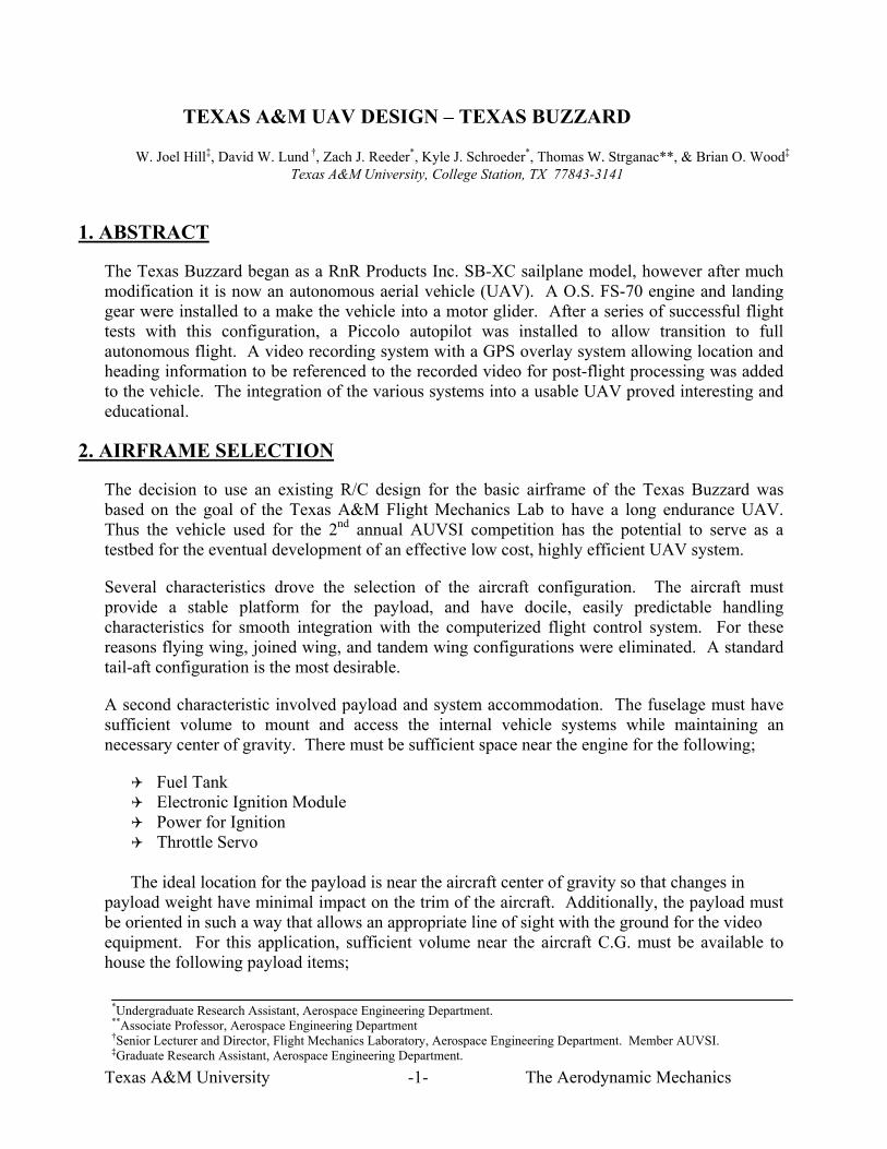
The SBXB was designed as a high performance cross country model sailplane. Super XC specifications appear in Table 3.1. The unmodified aircraft appears in Figure 3.11.
Texas A&M University -3- The Aerodynamic Mechanics
Table 3.1 Super XC Specifications
Parameter Quantity Units Wing Span 170 in Wing Area 1545 in2
Airfoil SD-2048 -- Aspect Ratio 18.7:1 -- Weight 9.5 Pounds Wing Loading 14 oz/ft2
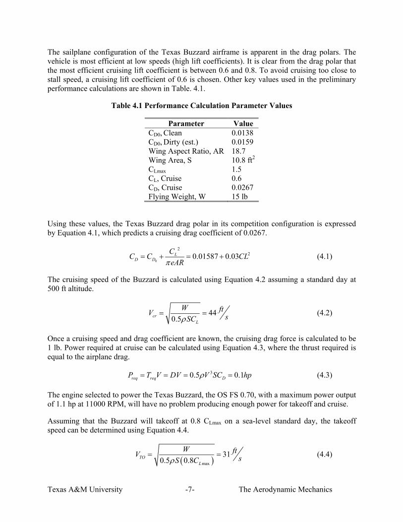
Figure 3.1 Super XC RC Sailplane
The Super XC has a conventional configuration with an all-flying horizontal tail. The aircraft utilizes a graphite push tube for the elevator linkage. The rudder linkage is a Kevlar cord pull-pull type. All control surfaces are controlled by electromechanical servos commercially available for RC aviation applications. The configuration of this aircraft met the needs of the Texas Buzzard UAV system.
One of the most appealing features of the Super XC is its payload volume. The semi-scale fuselage has a large volume forward of the wing in the simulated cockpit. Our flight tests of this unpowered sailplane showed the Super XC required approximately two pounds of ballast in the nose to achieve the recommended static margin. The large internal volume combined with the ballast requirement make the Super XC well suited for payload and engine installation, where the engine will replace the ballast.
Finally, the Super XC has the high airframe efficiency desired for the Texas Buzzard UAV system. This sailplane routinely thermals for four to eight hour flights. In addition to the 18.7 aspect ratio wing, the Super XC features faired control surface hinge lines and an all-flying tail. These features help reduce parasite drag and increase the aircraft lift to drag ratio. The wing is also fitted with part span flaps to help with glide slope control for approach. Obviously, the sailplane kit selected required significant modification in order to meet the mission goals.

Texas A&M University -4- The Aerodynamic Mechanics
Integration of the engine, payload and landing gear were required in order to complete the aircraft system. The general arrangement of internal components appears in Figures 3.2 and 3.3.
Figure 3.2 General Fuselage Layout
Figure 3.3 Fuselage Detail
3.1 FIREWALL
A plywood firewall was installed at the forward edge of the equipment bay access cover. Due to the volume constraints in the nose, the vibration damping engine mounts are mounted on the aft face of the firewall with the support arms extending forward into the engine compartment. This unique mounting scheme allowed a very compact engine installation. The throttle servo is mounted in an aluminum bracket captured by the starboard engine mount bolts.
3.2 LANDING GEAR
The addition of a tail dragger style landing gear represented one of the most significant structural modifications made to the aircraft. The tail dragger configuration was chosen because of the

Texas A&M University -5- The Aerodynamic Mechanics
weight and drag advantages over a tricycle landing gear. The main gear consists of a two part spring steel strut made from music wire. This spring-strut system attaches to plywood bulkheads attached to the original wing mount structure. Standard three inch RC model wheels are used. The aircraft has no brakes. The steering tail wheel is attached to the bottom of the fuselage near the original tail skid. A spring linkage attaches the tail wheel to the rudder and provides steering capability while the aircraft is on the ground. The landing gear installation is visible in Figure 3.4. The final configuration will feature main gear wheel fairings.
Figure 3.4 Landing Gear Installation
3.3 ENGINE:
For initial design and flight tests, an O.S. FS-91 engine was used to power the Texas Buzzard. This engine was selected because of its availability and fuel efficiency. The FS-91 is a four-stroke R/C engine that weighs approximately 1.5 lbs and produces about 1.6 hp at 11,000 RPM2. During initial flight testing, it was found that the aircraft was over-powered with this engine. The decision was made to replace the FS-91 with the smaller O.S. FS-70 engine. The FS-70 is also a four-stroke R/C engine, weighs about 1.36 lb, and produces about 1.1 hp at 11,000 RPM.
After the engine was selected, the primary design challenge of the engine installation was to integrate the engine into the aircraft with as little additional drag as possible. It was decided to integrate the engine in the existing fuselage with the propeller shaft protruding from the aircraft nose. The engine’s exhaust and cylinder head cooling vanes extend beyond the upper surface of the fuselage. This arrangement allows for adequate engine cooling and exhaust rejection while maintaining reasonable aerodynamic efficiency. The engine was mounted to the fuselage using the engine mount described in Section 3.1.
The engine was fitted with a 12 inch diameter APC propeller with a pitch of 8 inches. A Du-Bro exhaust gas deflector3 directs the dirty exhaust away from the aircraft. A small inlet in the bottom of the forward fuselage provides clean air to the carburetor. High pressure exhaust is drawn off to pressurize the fuel tank, thereby reducing the suction necessary for the engine to draw fuel into the cylinder. The engine configuration as installed in the airframe can be seen in Figure 3.5.

Texas A&M University -6- The Aerodynamic Mechanics
Figure 3.5 Engine Installation
Some modifications will be made to this engine to increase efficiency. These modifications will include replacing the glow plug with an electronic ignition to increase combustion reliability. This ignition is made by CH Ignitions4 and requires a separate battery pack and ignition module. For the competition we will us normal model aircraft fuel. Our design will eventually be modified to run on Coleman stove fuel. This fuel has a higher energy density than traditional aircraft fuels. It burns hotter and produces more power for a given amount of fuel. Since the fuel burns hotter, a special lubricant is needed to protect the engine, minimize the carbon build-up and help keep the engine running cooler. This lubricant is Indopol L-50 mixed at a ratio of 16 oz per gallon of fuel. Indopol L-50 is a high quality, lanolin-based oil used in the food processing industry. Several other fuel and carburetor system modifications are planned. Eventually, out team’s goal is to have a system that is very similar to that used by Maynard Hill on the record-setting TAM5 Atlantic-crossing5,6,7.
4. EXPECTED PERFORMANCE
The primary performance metric for the Texas Buzzard is a drag polar developed from flight testing of the airframe in a sailplane configuration with no engine or landing gear8. By measuring sink rates of the vehicle at different airspeeds with a known weight, a drag polar for the unpowered “clean” airplane can be constructed by curve fitting the measured lift and drag points. Assuming that the addition of the gas engine, propeller, and landing gear will add at most 15% to the zero-lift drag coefficient, the drag polar for the Texas Buzzard can be created. The drag polar is shown in Figure 4.1.
0
0.2
0.4
0.6
0.8
1
1.2
0 10 20 30L/D
CL
Experimental L/D
Calculated L/D
Figure 4.1 Clean Drag Polar: Calculated vs. Experimentally Determined
Texas A&M University -7- The Aerodynamic Mechanics
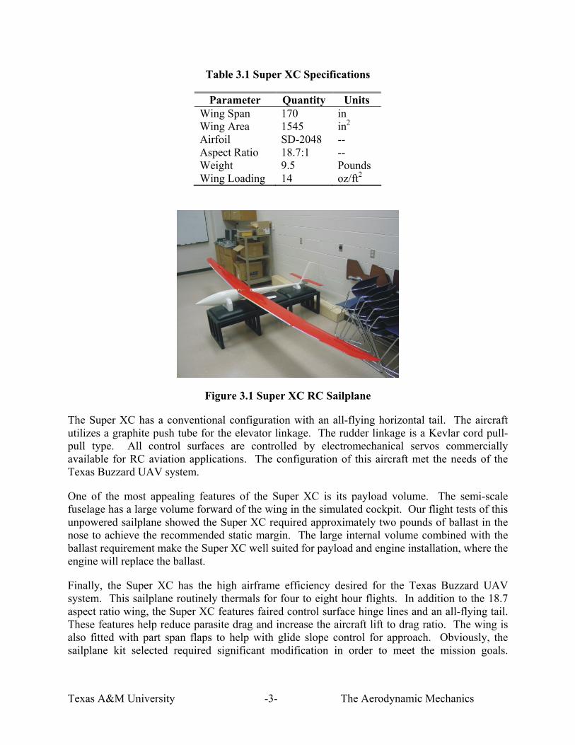
The sailplane configuration of the Texas Buzzard airframe is apparent in the drag polars. The vehicle is most efficient at low speeds (high lift coefficients). It is clear from the drag polar that the most efficient cruising lift coefficient is between 0.6 and 0.8. To avoid cruising too close to stall speed, a cruising lift coefficient of 0.6 is chosen. Other key values used in the preliminary performance calculations are shown in Table. 4.1.
Table 4.1 Performance Calculation Parameter Values
Parameter Value CD0, Clean 0.0138 CD0, Dirty (est.) 0.0159 Wing Aspect Ratio, AR 18.7 Wing Area, S 10.8 ft2
CLmax 1.5 CL, Cruise 0.6 CD, Cruise 0.0267 Flying Weight, W 15 lb
Using these values, the Texas Buzzard drag polar in its competition configuration is expressed by Equation 4.1, which predicts a cruising drag coefficient of 0.0267.
0
220.01587 0.03L
D DCC C CLeARπ
= + = + (4.1)
The cruising speed of the Buzzard is calculated using Equation 4.2 assuming a standard day at 500 ft altitude.
440.5cr
L
W ftV sSCρ= = (4.2)
Once a cruising speed and drag coefficient are known, the cruising drag force is calculated to be 1 lb. Power required at cruise can be calculated using Equation 4.3, where the thrust required is equal to the airplane drag.
30.5 0.1req req DP T V DV V SC hpρ= = = = (4.3)
The engine selected to power the Texas Buzzard, the OS FS 0.70, with a maximum power output of 1.1 hp at 11000 RPM, will have no problem producing enough power for takeoff and cruise.
Assuming that the Buzzard will takeoff at 0.8 CLmax on a sea-level standard day, the takeoff speed can be determined using Equation 4.4.
( )max
310.5 0.8TO
L
W ftV sS Cρ= = (4.4)

Texas A&M University -8- The Aerodynamic Mechanics
To calculate takeoff ground roll distance, the takeoff acceleration must be known9. Equation 2.5 gives an expression for aircraft acceleration during takeoff, before rotation, where g is acceleration due to gravity and Fc is the coefficient of rolling friction (typically about 0.03).
( )cga T D F W L
W⎛ ⎞= − − −⎡ ⎤⎜ ⎟ ⎣ ⎦⎝ ⎠
(4.5)
The expression for ground roll distance is given by Equation 4.6, where amean is the acceleration of the aircraft calculated from Equation 1.5 when V = 0.7VTO. For the pre-rotation takeoff ground roll, the wing is at an angle of attack of about 3°, with a CL of 0.5. From the drag polar, at this lift coefficient the airplane drag coefficient is 0.0234. The static thrust of the engine is 6.1 lb which will decrease with increasing speed. At V = 0.7VTO, the thrust will be approximately 75% of the static value. These values give an expected mean acceleration of 7.56 ft/s
2, which is used to calculate takeoff ground roll.
2
642
TOG
mean
Vs fta
= = (4.6)
5. AUTONOMY10
A Piccolo autopilot from Cloud Cap Technology was selected for use on the Texas Buzzard. The Piccolo’s reliability, rich development environment, and hardware-in-the-loop (HIL) simulator made it the ideal autopilot for AUVSI competition, as well as future UAV development at Texas A&M once the competition is complete.
Besides the proven reliability of the Piccolo, the hardware-in-the-loop simulation provides the greatest benefit to ensure a quick and successful autopilot implementation on the Texas Buzzard. Hardware-in-the-loop simulation should be considered a cornerstone of unmanned aircraft development. HIL simulation allows the aircraft control laws and mission functionality to be tested without risking the hardware in flight test. While HIL simulation will never replace flight testing, it certainly reduces the likelihood of failure in flight by detecting errors and deficiencies in the lab.
The Piccolo uses the advanced MPC555 microcontroller, based on the popular PowerPC architecture. The MPC555 marries an enormous array of interfaces to a powerful RISC engine that delivers 40Mhz PowerPC operation, including hardware floating point.
Piccolo uses three Tokin CG-16D rate gyros and three ADXL202 accelerometers to obtain inertial measurements. Additionally, the Piccolo includes a dual ported MPXV50045 4kPa dynamic pressure sensor, an absolute ported MPX4115A barometric pressure sensor, and an air temperature sensor. Together these sensors provide the ability to measure true air speed and altitude. These sensors are used as inputs to airspeed and altitude control loops within the autopilot. Piccolo uses the Motorola M12 GPS to provide its basic groundspeed and position. The M12 is differential capable, and by utilizing a M12 GPS receiver on the ground station, DGPS corrections can be sent over the data link to the Piccolo.

Texas A&M University -9- The Aerodynamic Mechanics
Waypoint navigation will be accomplished on the Texas Buzzard by using the Differential GPS to generate position and groundspeed; this information will then be used to generate a turn rate command to the autopilot. The navigation algorithm in Piccolo follows the great circle path defined by waypoints in a stored flight plan. The flight plan can be updated while in flight, however for the competition this information will be stored in the Piccolo prior to flight.
6. GROUND CONTROL STATION10
The Cloud Cap Piccolo ground station manages the communication link to one or more avionics systems, interfaces to the pilot in the loop console, and provides a command and control stream to the ground station display, hosted on the operator interface PC.
The main ground station display has a multitude of features which provide an exceptional level of information about and control of the Piccolo while in flight. The ground station displays a full telemetry set (Figure 6.1), including: GPS data, air data, attitude data, gyro data, engine RPM, wind estimates, radio settings, and system health.
Figure 6.1: Ground Station Telemetry Display
The autopilot commands display (Figure 6.2) shows the current autopilot command status, and allows you to change the commands. The Piccolo includes four main autopilot structures: Airspeed command and hold, Altitude command and hold, Turn Rate command and hold, and a GPS Waypoint Tracker. Commands for each of the autopilot structures can be set and changed from the autopilot display on the ground station.

Texas A&M University -10- The Aerodynamic Mechanics
Figure 6.2: Autopilot Commands Display
The map display (Figure 6.3) shows the current location of the vehicle, and provides an interface for creating flight plans. The map is capable of displaying geo-referenced raster files, as well as vector shape files, which allows the operator to track the progress of the vehicle more easily by referencing known ground objects.
The map displays the current waypoint based flight plans for the vehicle. There are two types of flight plans displayed: remote plans and local plans. Remote plans are those that are stored onboard the avionics, i.e. remote from the operator interface, and they are drawn in red. Local plans are those that are stored on the operator interface, i.e. they have not yet been sent to the avionics, and they are drawn in white. The Piccolo is capable of storing 100 waypoints. The waypoints are also capable of encoding altitude. Flight plans can easily be created by selecting waypoints on the map display or alternately by entering the desired latitude, longitude, and altitudes in a flight plan dialog box. When a new flight plan has been created it can be sent to the Piccolo autopilot by pressing the send button on the map display page.

Texas A&M University -11- The Aerodynamic Mechanics
Figure 6.3: Ground Station Map Display
In addition to the three ground station displays previously described, there are six other displays: Preflight, Limits, Sensors, Surfaces, Gains, and Payload. The Preflight page displays a simple checklist that can be used prior to flight to ensure that the avionics have been prepared for flight. The Limits page allows minimum and maximum values to be set for the airspeed, altitude, bank angle and aileron, elevator, rudder, throttle, and flap positions. It also allows mission limits to be set which trigger the deadman output. The deadman interface will be used in the competition to satisfy the radio fail-safe operating mode requirements outlined in the competition rules. Cloud Cap will provide us with an updated software package to allow this “aerodynamic termination” model The sensors page gives the current sensor readings and calibration information for each sensor. The surfaces page is used to control how the five autopilot outputs are mixed and matched to generate up to ten servo outputs; and also to provide the calibration information to go from surface angle to servo pulse width. The gains page is used to view and alter the autopilot gains. There are gains for seven loops: Dynamic Pressure, Altitude, Turn, Tracker, Roll, Pitch, Yaw, and Turn Compensator. Gains can be set prior to flight or tweaked as necessary while the Piccolo is in flight. The gains page also displays the current control surface positions. The payload page gives the user the ability to control the I/O lines on the external connector. No external payload control is planned for use in the competition.
7. DATA LINK10
Piccolo data link utilizes the MHX 910 radio modem from Microhard Systems Inc. The data link has up to 40Kbaud of throughput and is used for command and control, autopilot telemetry, payload data transfer functions, differential GPS corrections uplink, and pilot in the loop modes. The data link architecture allows multiple aircraft to be controlled by a single operator from a single ground station.
The MHX radio is a 900Mhz ISM band, frequency hopping radio with good receive sensitivity and a maximum 1 Watt output power. The wireless link formed between radios extends from all the avionics to the ground station. Communications going up from a ground station include an

Texas A&M University -12- The Aerodynamic Mechanics
address which identifies which avionics should process the information. Communications coming down from an avionics use the address to identify which avionics the data are coming from.
The data sent to or from any one avionics are made up of multiple bi-directional streams which are multiplexed onto the wireless channel. Each stream represents an endpoint in the avionics, which is either defined by software or by a physical port on the avionics.
The ground station manages flow control of the network, preventing multiple radios from transmitting at the same time. This is done by allowing one node of the network to dictate when every other node can talk, and for how long. Piccolo’s does this with a polled system in which the ground station polls each avionics in “round-robin” fashion. The Piccolo interface contains all the logic to run the polling scheme. If pilot in the loop commands are available the ground station sends them out as the first packet of each frame. If multiple aircraft are in the network then the avionics polls different addresses each frame, however the pilot command packet always contains the same address, the one specified by the operator interface for pilot in the loop commands. If no such specification has been received then the ground station does not send pilot in the loop commands.
After sending the pilot command, the ground station broadcasts differential corrections, if available, to all avionics. Then the ground station sends any data from the operator interface which was destined for the avionics addressed in that frame, up to the maximum amount of data allotted in that frame. Finally the ground station sends the polling packet with whatever data space remains in the frame. Any reply from the aircraft (except the frame terminator) is forwarded to the operator interface.
The MHX radio sends data in packets, with its own rudimentary network logic. It works by buffering up data from the host until the amount of data buffered reaches a specified maximum, or until the host stops sending data. When that happens the buffered data is formed into a packet (locally within the radio) and then queued for broadcast.
The MHX radio network hops from frequency to frequency at a user defined interval. The radios implement a master/slave architecture in which a single master radio (the ground station) broadcasts any data it has waiting at the beginning of the hop interval, and any and all slaves broadcast their data following the master, up to the end of the hop interval. With only one slave in the system there is no need to implement the flow control outlined in Table 1, since the slave radio will not broadcast when the master radio is broadcasting. However multiple slave radios require flow control since without it the slaves would attempt to transmit at the same time.
8. PAYLOAD
The payload for the Texas Buzzard is the imaging system. The imaging system records video of the ground with integrated GPS information. These images will be used in conjunction with GEOTIFF images of the Webster field area. This combination will allow target identification resolution orientation and reconnaissance.

Texas A&M University -13- The Aerodynamic Mechanics
The onboard imaging system includes a small (11.6 gms) Panasonic CX161 CCD color video camera. This camera has 330 TV lines resolution, 5 lux and 52 degree lens. The video camera is very small and extremely lightweight. The camera is mounted in the bottom of UAV, pointed. A GPS video overlay board OSD-GPS by Intuitive Circuits uses a separate 12 channel GPS system (PICO-GPS-SS from U-Nav) and overlays the current coordinates and speed of the vehicle onto the video image. Finally, this image is recorded on-board using a Sony DCR-IP1 Micro MV digital video recorder for on ground analysis. Size and weight information for the imaging system is provided in Table 8.1.
Table 8.1 Payload Size and Weight Data
Component Size [in] Weight [oz] Piccolo Autopilot 5.5 x 3 x 1.7 7.8
Piccolo Battery Pack 6.5 x 2 x 0.5 14 Piccolo GPS Antenna 1 x 0.75 x 0.25 0.8
Piccolo Datalink Antenna 4 x 0.5 x 0.5 1.7 Color Video Camera 1 x 1 x 0.75 0.4 GPS Overlay Board 4 x 3 x 1 0.7
Digital Video Recorder 3.5 x 2.6 x 1.5 10.2
To validate the function and integration of various payload subsystem, the entire imaging system was assembled and test flown several times on a scale Piper Cub R/C Model. Targets were painted on the ground at known locations on a runway, and video was taken of these targets from the air using the same imaging system which will be incorporated into the Texas Buzzard. A photo of the Cub model with the payload installed is shown in Figure 7.1.
Figure 8.1 Piper Cub Model with Imaging Payload Installed
9. SAFETY CONSIDERATIONS
A conventional hazard analysis was used to determine the failure modes and effects analysis which was then used to determine the procedures and test rules necessary for safely operating the Texas Buzzard. Three documents were produced by the Texas A&M team; 1. R/C and

Texas A&M University -14- The Aerodynamic Mechanics
Autonomous UAV Testing – Project Safety Analysis, 2. Hazard Analysis Plan and 3. the Standard Operating Procedures.
The hazard levels were assessed using the following definition:
Severity: I - Catastrophic, May cause death or UAV loss. II - Critical, May cause severe injury or major UAV damage. III - Marginal, May cause minor injury or UAV damage < $10,000. IV - Negligible, Will not result in injury or UAV damage. Probability: A - Frequent, Likely to occur within a short period of time. B - Probable, Probably will occur in time. C - Occasional, May occur in time. D - Remote, Unlikely to occur. The risk assessment was then performed, where risk is defined as “an expression of possible loss in terms of mishap severity and probability.” Loss is measured in lives, dollars, equipment and mission capability. Risk assessment, involves determining the hazard involved, predicting resulting frequency of occurrence, assessing severity or consequences, determining exposure and identifying action to avoid or minimize the risk. The risk that remains after the precautionary measures/corrective actions have been implemented is referred to as the “residual risk.”
Residual Risk Matrix
Mishap Probability
Hazard Severity
I (Catastrophic) II (Critical) III (Marginal) IV (Negligible)
A (Frequent) UA UA C B
B (Probable) UA C C A
C (Occasional) 1 C B A
D (Remote) B B A A
NOTES: 1 - The determination of a test project whose residual risk assessment falls under I/C will require up front discussions with TCT prior to proceeding with the test program development. UA - Unacceptable risk, project residual risk too high to proceed C - Test activities which present a significant risk to personnel, equipment or property, even after all precautionary/corrective actions are taken. B - Test activities which present a greater risk to personnel, equipment or property than normal operations. A - Test activities which present no greater risk than normal operations.

Texas A&M University -15- The Aerodynamic Mechanics
The complete hazard analysis for the Texas Buzzard is shown in the Appendix A. From this analysis the following hazards were identified;
Propeller Hazard - Propeller structural failure must also be anticipated. The potential impact zone for debris extends on the side of the propeller or impeller in-line with the rotation disc and to a lesser extent in front. Starting area will be set up clear of personnel not associated with starting and restraining the UAV. The area will be clear of debris for 24”’ in front and to the sides and 60” behind the UAV prior to engine start. Personnel responsible for starting the engine shall have eye protection, and use a starting stick or electric starter. THE PROPELLER IS NEVER TURNED BY HAND AFTER THE GLOW PLUG DRIVER IS ATTACHED OR AFTER THE CDI IGNITION SWITCH HAS BEEN TURNED ON. All test personnel/observers shall stay clear of a spinning propeller, & at all times will avoid standing to the side of the propeller disc.
At the end of a flight, the pilot will kill the engine either upon touch down or, if conditions allow for safe operation, after taxi back to the pit location. Ground handlers will verify the ignition and receiver power switch is in the “OFF” position prior to handling or moving the UAV.
Unintentional Engine Start Hazard - Four-stroke engines can be unintentionally started by turning the propeller if the glow plug driver or the electronic ignition switch is turned on. The glow plug driver shall not be installed except to run the engine. The electronic ignition switch shall not be turned on except to run the engine. A strobe light will be energized when the ignition switch is on.
Personnel & Equipment Impact Hazard - Aircraft loss of control represents an impact risk to test team and observers. The AMA recommended flying site specifications will be used as appropriate (as judged by the Test Safety Officer). For remote testing, suitable cars or other vehicles/tables etc can serve as protective fencing.
Given these hazards, the following operational rules were developed:
Personnel protection All ground test personnel not participating in the engine starting, launch or training for
launch activities will remain at least 20 feet from the UAV The ground handlers shall wear eye protection (goggles or safety glasses). Due to the
low noise level of these specific 4-stroke engines, the use of hearing protection is not required.
The wind speed seen by the R/C pilot will not exceed 14 mph as measured by a hand held wind speed gauge, or 17 mph as measured by the anemometer mounted ~10’ or more above the ground. Gusts limits are also important. No flying will be done if the gusts are over +/- 5 mph (with a 30 second period).
The test team shall have ready access to a fire extinguisher and a first aid kit whenever flight operations are conducted.
The Test Safety Officer will carry an operating cellular phone during all testing operations. The Test Safety Officer is responsible to ensure that its batteries are fully charged so as to last the expected duration of the test.

Texas A&M University -16- The Aerodynamic Mechanics
Test Commit Criteria
Flight test operations will cease immediately for 15 minute evaluation period if wind conditions exceed the following (determined by either a hand held wind gauge or by the anemometer:
o Total wind speed greater that 14 mph as measured at 6’ above the ground or 17 mph measured greater than 10’ above the ground.
o Wind >10 mph perpendicular to the planned landing or take-off. o Wind gusts in excess of +/- 5 mph. Any inclement weather such as rain or
lightning (observed within 10 miles), or loss of daylight shall terminate test operations until deemed safe by both the Test Director & the Test Safety Officer.
Failure of the radio receiver/aircraft to respond normally will result in test termination until the fault can be corrected.
Failure to pass engine on radio range check (for R/C control)
Personnel Training and Certification: All personnel shall complete hands-on fire extinguisher training. All test teams will be given a copy of the Academy of Model Aeronautics AMA National
Model Aircraft Safety Code
The following emergency procedures were also developed to mitigate the risks:
If personnel approach a spinning propeller:
Test Director Calls “STOP ENGINE”. Pilot drops throttle control on the transmitter and trim slider to engine kill switch. All personnel help in securing medical attention.
UAV is uncontrollable:
Pilot calls “LOSS of CONTROL” and kills engine Test Director notifies all Team Members and Observers of situation. Pilot adjusts UAV for landing, kills engine, lands in remote area. Ground Handler and Test Director safes the UAV and engine. Ground Handler and Test Director inspect for damage to UAV. Test operations are stopped until the UAV is repaired.
Fire Starts:
Person first noticing fire, calls “FIRE”. All personnel clear the area Test Safety Officer evaluates use of fire extinguisher and assigns closest person to the
extinguisher (Pilot, Ground Handler or Test Director) to extinguish the fire. If fire is uncontained, Test Safety Officer radios or calls fire department. All test personnel move 75 feet from UAV.

Texas A&M University -17- The Aerodynamic Mechanics

Texas A&M University -18- The Aerodynamic Mechanics
Appendix A. Texas Buzzard Hazard Analysis
Hazard Cause Effect Precautionary Measure Hazard Level based on
Residual Risk
Loss of Engine Fuel starvation/ Contamination, Carburetor, valves fouling/icing
Power-Off landing Fuel contamination and FOD programs Pilot proficiency in power off landings All flight operations within safe gliding distance of landing site
IV/C
Loss of Uplink Out of range flight. Antenna malfunction. Electrical malfunction
Loss of UAV control. Vehicle will not be able to be manually controlled should an avoidance maneuver be required. This poses a risk to other aircraft, or and people on the ground
Autopilot will provide appropriate response. For AUVSI competition, it will be Aerodynamic Termination (engine kill, aileron turn, elevator nose down, rudder turn). For other operations, the loss of link will cause the autopilot to steer to preprogrammed GPS waypoints and descend. Loss of uplink response will be verified prior to every autonomous flight. Antenna range proven to far exceed test requirements. Loss of uplink waypoint to be updated and verified before each flight. Battery charge checked prior to flight. Frequency coordination with other users (Appendix A)
IV/C
Autopilot malfunction
Internal electrical failure. Software problem. EMI disturbance
Vehicle may fly away from landing site. Loss of Uplink logic will not operate
Independent engine kill capability. Range check prior to flight operations Electronic shielding, and proper ground plane for the uplink receiver antenna.
IV/D
Loss of GPS signal
Electrical failure Loss of satellite lock
None during manual flight Autonomous flight. Navigation errors for autonomous flight.
GPS lock will be verified before takeoff. GPS antenna ground plane installation. Engine kill functionality verified before every flight Pilot will take manual control should the GPS system fail.
IV/D
Loss of Steering Control
Servo malfunction.
Unable to steer vehicle. UAV not controllable should an avoidance maneuver be required.
Independent engine kill capability verified before every flight All flight operations within safe gliding distance of landing site
III/C
Loss of Throttle Control
Ground station failure. Mechanical failure in UAV.
Vehicle may descend or climb depending on failure state
Throttle control verified before and immediately after takeoff Engine Kill capability verified before every flight Limited fuel on board
IV/D
Test personnel impacting propeller
Too close proximity to UAV during takeoff run.
Injury to personnel and propeller
Launch process modified to include a tie-down strap for vehicle. Ground handlers will be NLT 10 ft away during ALL test operations. Ignition switch mounted in a location visible to ground observers. External strobe light tied to ignition circuit.
II/D
Vehicle impacts test team personnel
Crosswind operations Out of control vehicle Structural failure
Injury to personnel No flight operations will be performed over test team personnel Flight path of vehicle predetermined so trajectory of falling vehicle will not endanger ground personnel. Simple structural test – lifting the UAV off the ground by the wing
II/D

Texas A&M University -19- The Aerodynamic Mechanics
REFERENCES 1 RnR Products, Sailplanes, “SBXC”, 13 May 2004, http://www.rnrproducts.com/ 2 OS Engines, 13 May 2004, http://www.osengines.com/engines/surpass.html 3 Du-Bro Corp., 13 May 2004, http://www.dubro.com/DU-BRO/DUB_CAT/Dub_cat_Frameset.htm 4 CH Ignitions, 13 May 2004, http://www.ch-ignitions.com 5 Hill, Maynard, Article. Model Aviation. <http://www.modelaircraft.org/mag/mhill/ hillindex.htm> (5/10/04) 6 Bell, Rick, “Record –Setting Transatlantic Flight”, Model Aircraft News, January 2004, Volume 132, Number 1, page 84-88. 7 Hill, Maynard, “Two Sunsets & Still Flying, Model Aviation, January 2004,Volume 30, Number 1, pg 18-28. 8 Ellias, John, “Performance Testing of RNR’s SBXC Using GPS”, 15 March 2004, www.xcsoaring.com/articles/john_ellias_1/ sbxc_performance_test.pdf 9 Nicolai, Leland M., “Estimating Model Aerodynamics and Performance”, Lockheed Martin Aeronautics Company, June 2002. 10 Cloud Cap Technologies, Inc., www.cloudcaptech.com