tests with codes
DESCRIPTION
Cadillac OBD 1 , 1995 test and error codes explained and how to do it.TRANSCRIPT

G - TESTS W/CODES - 4.6LArticle Text
1995 Cadillac ConcoursFor Ace Mechanics 123 Main Street San Diego Ca 92126
Copyright © 1997 Mitchell InternationalFriday, November 28, 2003 07:15PM
ARTICLE BEGINNING
1995 ENGINE PERFORMANCE General Motors Corp. Self-Diagnostics - 4.6L
Cadillac; Concours
INTRODUCTION
If no trouble codes were found while performing BASICDIAGNOSTIC PROCEDURES, proceed with self-diagnostics. If no faultcodes or only pass codes are present after entering self-diagnostics,proceed to H - TESTS W/O CODES article in the ENGINE PERFORMANCEsection for diagnosis by symptom (i.e., ROUGH IDLE, NO START, etc.).
SELF-DIAGNOSTIC SYSTEM
NOTE: Electronic Control Module (ECM) and Powertrain Control Module (PCM) are the same system. Terms are often used interchangeably.
Self-diagnostic system consists of 6 components. Thesecomponents are Powertrain Control Module (PCM), Instrument PanelCluster (IPC) options, A/C Programmer (ACP) options, SupplementalInflatable Restraint (SIR) system, Traction Control system (TCS) andRoad Sensing Suspension (RSS) system options. In addition to monitoring a particular set of sensors andswitches, PCM maintains continuous communication with each systemcomponent. Should a component exceed pre-programmed limits, PCM willrecognize a malfunction and may act to control malfunctioningcomponent. To control a particular component, PCM rapidly switches aninternal circuit between zero and 5 volts, converting programmedcontrol information into series of pulses that represents coded serialdata messages. These messages are transmitted to malfunctioningcomponent, which interprets information and responds accordingly. As a result, an alphanumeric code, known as a trouble code,is often set in PCM memory. This trouble code identifiesmalfunctioning component and can be accessed by a service technicianas an aid to diagnostic procedures. All trouble codes are displayed onDriver Information Center (DIC) panel. In addition to monitoring self-diagnostic system anddisplaying trouble codes, PCM can be programmed by service technicianto perform specific diagnostic tests on individual components andsystems. Results of these tests are displayed on DIC. This articlecovers accessing PCM trouble codes and programming self-diagnosticsystem to perform specific diagnostic tests on system components.

G - TESTS W/CODES - 4.6LArticle Text (p. 2)1995 Cadillac ConcoursFor Ace Mechanics 123 Main Street San Diego Ca 92126
ENTERING SELF-DIAGNOSTICS
1) Turn ignition on. Simultaneously push OFF and WARMERbuttons on Climate Control Center (CCC). Continue pushing OFF andWARMER buttons until segment check appears (about 3 seconds) onInstrument Panel Control (IPC).
NOTE: Failure of any segment to glow may result in inaccurate test results. Replace any inoperative segment display before proceeding with self-diagnostic process.
2) When segment check appears (all segments glow), system hasentered self-diagnostic mode. Release both buttons. Driver InformationCenter (DIC) will display diagnostic codes. Diagnostic code leveldisplays PCM codes first, followed by IPC, ACP, SIR, TCS and RSS codes(if so prompted). 3) To proceed to desired level, press and release CCC HI (fanup) button for "yes" or LO (fan down) button for "no". Depress LObutton to go to next test level (i.e., IPC?, ACP?, SIR?, TCS? or RSS?)or depress OFF button to return to next selection in previous testlevel. 4) To exit diagnostics, press AUTO or DEFOG button on IPC.System will go back to normal vehicle operation.
DISPLAYING TROUBLE CODES
1) Trouble codes appear in ascending (3-digit) numericalorder and are prefixed by "P" (PCM), "I" (IPC), "A" (ACP), "R" (SIR),"T" (TCS) or "S" (RSS). A final digit of either a "C" (current) or "H"(history)" will also be indicated on every code. Diagnostic code leveldisplays PCM codes first, followed by IPC, ACP, SIR, TCS or RSS codes(if so prompted). 2) For complete list of available PCM trouble codes, see PCMTROUBLE CODES table. If no codes are present for a system, a "NO XCODE" message (with X being system, i.e. "P", "I", etc.) will bedisplayed. If communication line to a component is not operating, a"NO X DATA" message will be displayed, indicating that IPC could notcommunicate with that system. 3) To continue with system diagnostics, see SERVICE MODEOPERATION. To exit from SERVICE MODE and go back to normal vehicleoperation, depress AUTO or DEFOG button on CCC.
PCM TROUBLE CODES TABLEÄÄÄÄÄÄÄÄÄÄÄÄÄÄÄÄÄÄÄÄÄÄÄÄÄÄÄÄÄÄÄÄÄÄÄÄÄÄÄÄÄÄÄÄÄÄÄÄÄÄÄÄÄÄÄÄÄÄÄÄÄÄÄÄÄÄÄÄÄÄCode Test Condition
P012 (1) ................. No 4X Signal From Ignition Control ModuleP013 (1) .............................. Rear Oxygen Sensor Not Ready

G - TESTS W/CODES - 4.6L
P014 (1) ................ Shorted Engine Coolant Temp. Sensor SignalP015 (1) ................... Open Engine Coolant Temp. Sensor SignalP016 (2) (4) (5) (6) (7) ........... Alternator Voltage Out Of RangeP017 (1) ............................. Front Oxygen Sensor Not ReadyP019 (2) ................................. Shorted Fuel Pump CircuitP020 (2) .................................... Open Fuel Pump CircuitP021 (1) (4) ............................. Shorted TP Sensor CircuitP022 (1) (4) ................................ Open TP Sensor CircuitP023 (1) .......................... Ignition Control Circuit ProblemP024 (1) (4) .................. Vehicle Speed Sensor Circuit ProblemP025 (2) .................................. 24X Reference Signal LowP026 (1) (6) ............................. Shorted TP Sensor CircuitP027 (1) (6) ................................ Open TP Sensor CircuitP028 (1) ................. Transaxle Pressure Switch/Circuit ProblemP029 (1) ...................... Transaxle Shift Solenoid "B" ProblemP030 (1) ................. Idle Speed Control (ISC) RPM Out Of RangeP031 (1) (7) ............................ Shorted MAP Sensor CircuitP032 (1) (7) ............................... Open MAP Sensor CircuitP033 (2) (5) ............... Extended Travel Brake Sw. Input CircuitP034 (1) (7) ............................ MAP Sensor Signal Too HighP035 (3) ...................... Ignition Ground Voltage Out Of RangeP036 (1) (6) ...................... EGR Pintle Position Out Of RangeP037 (1) .................... Shorted Intake Air Temp. Sensor SignalP038 (1) ....................... Open Intake Air Temp. Sensor SignalP039 (1) (4) ...... Torque Converter Clutch (TCC) Engagement ProblemP040 (1) ....................... Power Steering Pressure Switch OpenP041 (1) ................. No Cam Sensor Signal From Ignition ModuleP042 (1) ........................... Front Oxygen Sensor Lean SignalP043 (1) ........................... Front Oxygen Sensor Rich SignalP044 (1) ............................ Rear Oxygen Sensor Lean SignalP045 (1) ............................ Rear Oxygen Sensor Rich SignalP046 (1) ...................... Front-To-Rear Bank Fueling ImbalanceP047 (2) ...................................... PCM/BCM Data ProblemP048 (1) (7) ...................................... EGR System FaultP051 (1) ................................................ PROM ErrorP052 (3) ............................... PCM Keep Alive Memory ResetP053 (3) ........ 4X Reference Signal Interrupt From Ignition ModuleP055 (1) .................................... TP Sensor Out Of RangeP056 (1) .............. Transaxle Input Speed Sensor Circuit ProblemP057 (2) .............. Shorted Transaxle Temperature Sensor CircuitP058 (8) ........................... PASS-Key(R) Fuel Enable ProblemP059 (2) ................. Open Transaxle Temperature Sensor CircuitP060 (3) (5) ............... Cruise Control - Transaxle Not In DriveP061 (3) (5) ................ Cruise Control - Vent Solenoid ProblemP062 (3) (5) .............. Cruise Control - Vacuum Solenoid ProblemP063 (3) (5) .................. Vehicle Speed & Set Speed DifferenceP064 (3) (5) ......................... Vehicle Acceleration Too HighP065 (3) (5) .......... Cruise Control Servo Position Sensor Failure
G - TESTS W/CODES - 4.6L
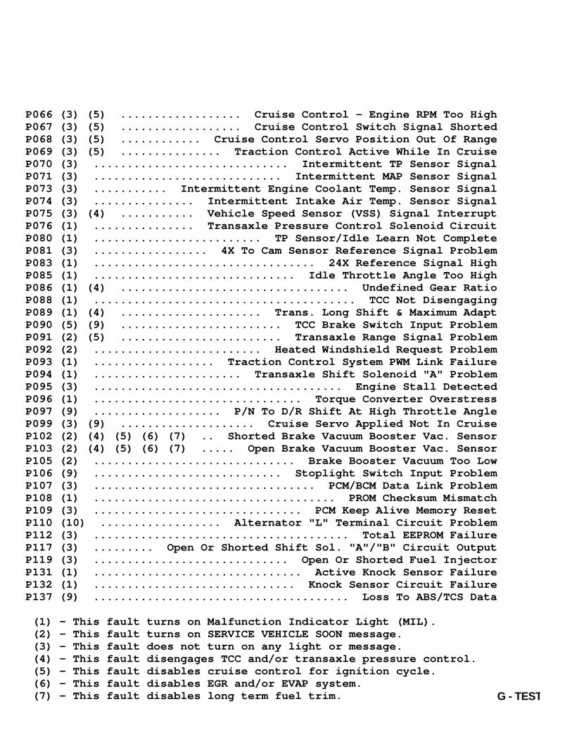
P066 (3) (5) .................. Cruise Control - Engine RPM Too HighP067 (3) (5) .................. Cruise Control Switch Signal ShortedP068 (3) (5) ............ Cruise Control Servo Position Out Of RangeP069 (3) (5) ............... Traction Control Active While In CruiseP070 (3) ............................. Intermittent TP Sensor SignalP071 (3) ............................ Intermittent MAP Sensor SignalP073 (3) ........... Intermittent Engine Coolant Temp. Sensor SignalP074 (3) ............... Intermittent Intake Air Temp. Sensor SignalP075 (3) (4) ........... Vehicle Speed Sensor (VSS) Signal InterruptP076 (1) ............... Transaxle Pressure Control Solenoid CircuitP080 (1) ......................... TP Sensor/Idle Learn Not CompleteP081 (3) ................. 4X To Cam Sensor Reference Signal ProblemP083 (1) ................................. 24X Reference Signal HighP085 (1) .............................. Idle Throttle Angle Too HighP086 (1) (4) .................................. Undefined Gear RatioP088 (1) ....................................... TCC Not DisengagingP089 (1) (4) ..................... Trans. Long Shift & Maximum AdaptP090 (5) (9) ........................ TCC Brake Switch Input ProblemP091 (2) (5) ........................ Transaxle Range Signal ProblemP092 (2) ......................... Heated Windshield Request ProblemP093 (1) .................. Traction Control System PWM Link FailureP094 (1) ...................... Transaxle Shift Solenoid "A" ProblemP095 (3) ..................................... Engine Stall DetectedP096 (1) ............................... Torque Converter OverstressP097 (9) ................... P/N To D/R Shift At High Throttle AngleP099 (3) (9) .................... Cruise Servo Applied Not In CruiseP102 (2) (4) (5) (6) (7) .. Shorted Brake Vacuum Booster Vac. SensorP103 (2) (4) (5) (6) (7) ..... Open Brake Vacuum Booster Vac. SensorP105 (2) .............................. Brake Booster Vacuum Too LowP106 (9) ............................ Stoplight Switch Input ProblemP107 (3) ................................. PCM/BCM Data Link ProblemP108 (1) .................................... PROM Checksum MismatchP109 (3) ............................... PCM Keep Alive Memory ResetP110 (10) .................. Alternator "L" Terminal Circuit ProblemP112 (3) ...................................... Total EEPROM FailureP117 (3) ......... Open Or Shorted Shift Sol. "A"/"B" Circuit OutputP119 (3) ............................. Open Or Shorted Fuel InjectorP131 (1) ............................... Active Knock Sensor FailureP132 (1) .............................. Knock Sensor Circuit FailureP137 (9) ...................................... Loss To ABS/TCS Data
(1) - This fault turns on Malfunction Indicator Light (MIL). (2) - This fault turns on SERVICE VEHICLE SOON message. (3) - This fault does not turn on any light or message. (4) - This fault disengages TCC and/or transaxle pressure control. (5) - This fault disables cruise control for ignition cycle. (6) - This fault disables EGR and/or EVAP system. (7) - This fault disables long term fuel trim.

G - TESTS W/CODES - 4.6LArticle Text (p. 5)
(8) - This fault turns on "THEFT SYSTEM PROBLEM - CAR MAY NOT RESTART" message. (9) - This fault turns on "REDUCED ENGINE POWER" message.(10) - This fault turns on "BATTERY NO CHARGE" message.ÄÄÄÄÄÄÄÄÄÄÄÄÄÄÄÄÄÄÄÄÄÄÄÄÄÄÄÄÄÄÄÄÄÄÄÄÄÄÄÄÄÄÄÄÄÄÄÄÄÄÄÄÄÄÄÄÄÄÄÄÄÄÄÄÄÄÄÄÄÄ
STATUS LIGHTS DISPLAY
Upon entering PCM system level of self-diagnostic mode,indicator lights on Climate Control Center (CCC) are used to indicatestatus of certain operating modes. Operational status of thesecomponents is indicated by corresponding status light being on or off.See Fig. 1.
Fig. 1: Identifying PCM Status IndicatorsCourtesy of General Motors Corp.
SERVICE MODE OPERATION
NOTE: IPC, ACP, SIR, TCS and RSS systems can also be tested in SERVICE MODE. Only information related to PCM diagnosis is covered in this article.
After PCM trouble codes have been displayed, SERVICE MODE canbe used to exit diagnostics or individually perform other tests ondifferent systems.
Selecting System Level
G - TESTS W/CODES - 4.6LArticle Text (p. 6)1995 Cadillac Concours
Following trouble code display, first available system willbe displayed (i.e., PCM?). When selecting a system to test, any offollowing actions may be taken to control display: 1) Depressing HI (fan up) button on CCC will select displayedsystem for testing (i.e., PCM DATA, PCM INPUTS, PCM OUTPUTS, etc.).See Fig. 2. 2) Depressing LO (fan down) button on CCC will display nextavailable system selection (i.e., IPC?, ACP? or SIR?). This allowsdisplay to be cycled through all system choices. This list of systemscan be repeated following end of system list. 3) Depressing OFF button on CCC will stop system selectionprocess and return display to beginning of PCM trouble code sequence.
Selecting Test Type Level Selection of "DATA?", "INPUTS?", "OUTPUTS?", "OVERRIDES?","CLEAR CODES?" or "SNAPSHOT?" test type may be displayed. See Fig. 2.If dashes appear in DIC, test is not valid or test conditions arewrong. While selecting a specific test, any of following actions maybe taken to control display: 1) Depressing HI (fan up) button on CCC will display aspecific output or test parameter for selected test type level (i.e.,PCM data parameter PD01,etc.). See Fig. 2. 2) Depressing LO (fan down) button on CCC will display nexttest type level for system level (i.e., PCM INPUTS?, PCM OUTPUTS?,etc.). See Fig. 2. This allows display to be cycled through allavailable test type choices. This list of test types can be repeatedfollowing display of last test type. 3) Depressing OFF button on CCC will stop test selectionprocess and return display to next system level (i.e., IPC?).
Selecting Clear Codes Selecting "CLEAR CODES?" test will result in "CODES CLEAR"message being displayed with selected system name for 3 seconds,indicating all stored trouble codes have been erased from memory.After 3 seconds, display will automatically return to next availabletest type level (i.e., PCM SNAPSHOT?). After a code has been cleared, make a complete ignitioncycle and possibly a test drive. Ensure code does not reset.

G - TESTS W/CODES - 4.6LArticle Text (p. 7)1995 Cadillac ConcoursFor Ace Mechanics 123 Main Street San Diego Ca 92126
Fig. 2: SERVICE MODE ChartCourtesy of General Motors Corp.
PCM LOCATION
PCM is located behind right kick panel.
DIAGNOSTIC PARAMETERS
PCM SPECIFIC DATA CODES
PD01: Throttle Position (TP) Sensor Display shows degrees of throttle opening from -13.9 to 93.4.
PD02: Manifold Air Pressure (MAP) Sensor reading is displayed in kilopascals (kPa) from 10 to105. With key on, engine off, MAP value will reflect barometricpressure. Multiply local barometric pressure by 3.386 to obtain MAPvalue within 2 kPa of displayed value with ignition on. MAP will alsovary with altitude.
PD03: Computed Barometric Pressure (BARO) Reading is displayed in kilopascals (kPa) from 61 to 103.

G - TESTS W/CODES - 4.6L
BARO pressure reading is taken with key on and engine off, and iscorrected at Wide Open Throttle (WOT). Multiply local barometricpressure by 3.386 kPa to obtain a BARO value within 2 kPa of displayedvalue. BARO varies with altitude (i.e., sea level 100 kPa, Denver 85kPa).
PD04: Engine Coolant Temperature (ECT) Sensor Display shows temperature in degrees Celsius (øC) from -40 to151.
PD05: Intake Air Temperature (IAT) Sensor Reading is displayed in degrees Celsius (øC) from -40 to 151.
PD07: EGR Pintle Position Display shows position of EGR pintle in counts from zero to255 based on feedback PCM receives from EGR valve.
PD08: Spark Advance Display shows timing advance in degrees BTDC as generated byignition control signal from PCM. Range of display is -20 to 70degrees.
PD09: Ignition Ground Voltage Display shows voltage difference between circuit No. 453(ignition ground) and PCM ground shifted 2.5 volts. A reading of 2.500volts means ignition and PCM grounds are at the same voltage. Areading of 1.000 means ignition ground voltage is 1.5 volts lower thanPCM ground and a reading of 3.500 means ignition ground voltage is 1.0volt greater than PCM ground. Display shows ignition ground voltagelevel from .003-4.970 volts.
PD10: Fuel Pump Feedback Voltage Voltage measured at fuel pump feedback circuit No. 120.Displayed in volts from zero to 25.5.
PD11: Engine Speed (RPM) Displayed in RPM from zero to 6375.
PD12: Vehicle Speed (MPH) Displayed in MPH from zero to 255.
PD13: EGR Pintle Position (Rescued) Display shows position of EGR pintle in percent of potentialpintle travel from zero to 100 based on feedback PCM receives from EGRvalve.
PD15: Ignition 1 Voltage Display shows ignition voltage measured on circuit No. 539,

G - TESTS W/CODES - 4.6L
PCM pin No. 2D5. Displayed in volts from zero to 25.5.
PD16: PCM Output Fault Status A Test shows state of fault lines from 4 of PCM's quad-drivers.Each quad-driver corresponds to one digit of display and each digitcan only appear as "0" or "1". A "0" means that no output faults arepresent. A "1" means that a fault is present in at least one output ofthat quad-driver. See QUAD-DRIVER IDENTIFICATION TABLE.
QUAD-DRIVER IDENTIFICATION TABLEÄÄÄÄÄÄÄÄÄÄÄÄÄÄÄÄÄÄÄÄÄÄÄÄÄÄÄÄÄÄÄÄÄÄÄÄÄÄÄÄÄÄÄÄÄÄÄÄÄÄÄÄÄÄÄÄÄÄÄÄÄÄÄÄÄÄÄÄÄÄQuad-Driver Outputs Driven
"A" (1st Digit) (1) .............. TCC Solenoid & Engine Temp. Light"B" (2nd Digit) ........ Pass-Key Starter Inhibit Output & EVAP Sol."C" (3rd Digit) ............................ Cooling Fan Relay & MIL"D" (4th Digit) ........... A/C Clutch Relay, TCS Delivered Torque & RSS Lift/Dive Outputs
(1) - "A" will be shown as "1" when brakes are applied.ÄÄÄÄÄÄÄÄÄÄÄÄÄÄÄÄÄÄÄÄÄÄÄÄÄÄÄÄÄÄÄÄÄÄÄÄÄÄÄÄÄÄÄÄÄÄÄÄÄÄÄÄÄÄÄÄÄÄÄÄÄÄÄÄÄÄÄÄÄÄ
PD17: PCM Output Fault Status B Test shows states of fault lines from one PCM quad-driver,the 8 injector drivers and the alternator enable circuit. Each quad-driver corresponds to one digit of display and each digit can onlyappear as "0" or "1". A "0" means no output faults are present. A "1"means a fault is present in at least one output of that quad-driver.See QUAD-DRIVER IDENTIFICATION TABLE.
QUAD-DRIVER IDENTIFICATION TABLEÄÄÄÄÄÄÄÄÄÄÄÄÄÄÄÄÄÄÄÄÄÄÄÄÄÄÄÄÄÄÄÄÄÄÄÄÄÄÄÄÄÄÄÄÄÄÄÄÄÄÄÄÄÄÄÄÄÄÄÄÄÄÄÄÄÄÄÄÄÄQuad-Driver Outputs Driven
"E" (1st Digit) (1) .................. TCC Shift Solenoids "A" & "B""F" (2nd Digit) ..................................... Fuel Injectors"G" (3rd Digit) (1) .................... Alternator "L" Term. Output"H" (4th Digit) ........................................... Not Used
(1) - "G" will be shown as "1" when ignition is on, engine off.ÄÄÄÄÄÄÄÄÄÄÄÄÄÄÄÄÄÄÄÄÄÄÄÄÄÄÄÄÄÄÄÄÄÄÄÄÄÄÄÄÄÄÄÄÄÄÄÄÄÄÄÄÄÄÄÄÄÄÄÄÄÄÄÄÄÄÄÄÄÄ
PD30: Front Bank Injector Pulse Width Display shows pulse width for cylinders No. 2, 4, 6 and 8 inmilliseconds (ms) from zero to 99.6.
PD31: Rear Bank Injector Pulse Width Display shows pulse width for cylinders No. 1, 3, 5 and 7 in

G - TESTS W/CODES - 4.6L
milliseconds (ms) from zero to 99.6.
PD32: Front Oxygen Sensor Voltage Display shows volts from zero to 1.16.
PD33: Rear Oxygen Sensor Voltage Display shows volts from zero to 1.16.
PD34: Front Oxygen Sensor Cross Counts Display shows counts from zero to 255. Cross count is numberof times voltage crosses the .45-volt reference in one second.
PD35: Rear Oxygen Sensor Cross Counts Display shows counts from zero to 255. Cross count is numberof times voltage crosses the .45-volt reference in one second.
PD36: Front Bank Short Term Fuel Trim Display shows counts from zero to 255. Normal integratorcount position is 128, indicating engine is operating normally. Acount greater than 128 indicates time is being added to injector pulsewidth, increasing amount of fuel to engine. A count of less than 128indicates time is being subtracted from injector pulse width, reducingamount of fuel to engine to compensate for a rich condition sensed atfront oxygen sensor.
PD37: Rear Bank Short Term Fuel Trim Displayed in counts from zero to 255. Normal integrator countposition is 128, indicating engine is operating normally. A countgreater than 128 indicates time is being added to injector pulsewidth, increasing amount of fuel to engine. A count of less than 128indicates time is being subtracted from injector pulse width, reducingamount of fuel to engine to compensate for a rich condition sensed atfront oxygen sensor.
PD38: Front Bank Long Term Fuel Trim Displayed in counts from zero to 255. Normal count positionfor long term fuel trim is 128, indicating engine is operatingnormally. Long term fuel trim value is based on short term learnedvalue, stored in memory blocks of long term according to MAP and RPMvalues. A count greater than 128 indicates time is being added toinjector pulse width, resulting in more fuel to engine. A count ofless than 128 indicates time is being subtracted from injector pulsewidth, resulting in less fuel to engine.
PD39: Rear Bank Long Term Fuel Trim Display shows counts from zero to 255. Normal count positionlong term fuel trim is 128, indicating engine is operating normally.Long term fuel trim value is based on short term learned value, stored

G - TESTS W/CODES - 4.6L
in memory blocks of long term memory according to MAP and RPM values.A count greater than 128 indicates time is being added to injectorpulse width, resulting in more fuel to engine. A count of less than128 indicates time is being subtracted from injector pulse width,resulting in less fuel to engine.
PD40: Knock Sensor Spark Retard Display shows amount of spark retard due solely to knocksensor input in degrees from zero to 44.8.
PD41: Knock Sensor Display shows the number of instances of engine detonationdetected by knock sensor in 1/8 of a second from zero to 255.
PD42: Octane Level Of Fuel Display shows octane level of fuel based on recent knocksensor activity. This parameter will only display zero, 87, 90 or 93indicating fuel octane calculated by PCM. A parameter value of zeroindicates that PCM has not enough time to calculate the octane level.Display will always read zero for vehicles equipped with 4.6L (VIN Y)engine.
PD69: Cruise Lash Display shows amount of cruise lash as a percentage of cruiseservo travel from 0.0-99.9 percent. Cruise lash in amount of slackfound in cruise control cable at closed throttle. A normal cruise lashpercentage should be 13-31 percent.
PD70: Cruise Control Feedback Display shows percentage of servo apply as measured by servoposition sensor. Zero equals no vacuum and 99 equals full vacuum (fullapply).
PD71: Transaxle Pressure Switch Display shows selected transaxle gear based on input fromtransaxle pressure switch in a 3-digit binary code from 000-111.Display will read 111 with key on, engine off.
TRANSAXLE PRESSURE SWITCH BINARY CODE TABLEÄÄÄÄÄÄÄÄÄÄÄÄÄÄÄÄÄÄÄÄÄÄÄÄÄÄÄÄÄÄÄÄÄÄÄÄÄÄÄÄÄÄÄÄÄÄÄÄÄÄÄÄÄÄÄÄÄÄÄÄÄÄÄÄÄÄÄÄÄÄCode Gear Range
000 ........................................................ Illegal001 ........................................................ Drive 4010 ........................................................ Illegal011 ........................................................ Drive 3100 ........................................................ Reverse101 ................................................... Park/Neutral

G - TESTS W/CODES - 4.6L
110 ........................................................ Drive 1111 ........................................................ Drive 2ÄÄÄÄÄÄÄÄÄÄÄÄÄÄÄÄÄÄÄÄÄÄÄÄÄÄÄÄÄÄÄÄÄÄÄÄÄÄÄÄÄÄÄÄÄÄÄÄÄÄÄÄÄÄÄÄÄÄÄÄÄÄÄÄÄÄÄÄÄÄ
PD72: Transaxle Input Speed Display shows the turbine shaft speed from zero to 8192 RPM.
PD73: Torque Converter Slip Speed Display shows amount of slippage between engine and transaxleinput shaft from zero to 8192 RPM.
PD74: Transaxle Pressure Control Solenoid Current Display shows calculated current output from PCM to drive thetransaxle pressure control solenoid. This current is calculated by PCMbased on the duty cycle of the signal it is sending out and isdisplayed in amps from 0-4.98.
PD75: Current Error Transaxle pressure control solenoid current error. Displayshows difference between calculated transaxle pressure controlsolenoid current output and that measured by the PCM at pin No. 2C15across the control solenoid current feedback resistor.
PD76: Transaxle Gear Ratio Display shows calculated gear ratio of transaxle based ontransaxle input speed and vehicle speed with the final drive ratiosubtracted out. If gear ratio difference is greater than 5 percent ofspecified ratio, Code P086 will set. See TRANSAXLE GEAR RATIO table.
TRANSAXLE GEAR RATIO TABLEÄÄÄÄÄÄÄÄÄÄÄÄÄÄÄÄÄÄÄÄÄÄÄÄÄÄÄÄÄÄÄÄÄÄÄÄÄÄÄÄÄÄÄÄÄÄÄÄÄÄÄÄÄÄÄÄÄÄÄÄÄÄÄÄÄÄÄÄÄÄGear Ratio
1st ........................................................... 2.962nd ........................................................... 1.633rd ............................................................ .004th ........................................................... 0.68Reverse ....................................................... 2.13ÄÄÄÄÄÄÄÄÄÄÄÄÄÄÄÄÄÄÄÄÄÄÄÄÄÄÄÄÄÄÄÄÄÄÄÄÄÄÄÄÄÄÄÄÄÄÄÄÄÄÄÄÄÄÄÄÄÄÄÄÄÄÄÄÄÄÄÄÄÄ
PD77: Transaxle Oil Temperature Display shows transaxle oil temperature in degrees Celsiusfrom -40 to 152.
PD78: Transaxle Shift Adapt Display shows readings of -128 to +127 psi. This value is theincrease or decrease in transaxle line pressure that PCM is commandingthrough the transaxle pressure control solenoid during the most recent

G - TESTS W/CODES - 4.6L
upshift or downshift. PCM increases or decreases line pressure duringshifts to control shift feel. Normal value fluctuates within a rangeof 20 psi. A value less than zero psi means PCM was lowering transaxleline pressure during most recent shift to soften the shift. A valuegreater than zero psi means PCM was raising transaxle line pressureduring most recent shift to firm up the shift.
PD79: Transaxle Steady State Adapt Display shows pressure from zero to +127 psi. This value isthe increase in transaxle line pressure that PCM is commanding throughthe transaxle pressure control solenoid during steady state, notupshifting or downshifting condition. PCM increases line pressure tocontrol clutch slippage. Normal value is 0-10 psi. A value greaterthan zero psi means that PCM has detected some clutch slippage (notduring transaxle shifts) and is raising transaxle line pressure todecrease transaxle clutch slippage.
PD80: Transaxle Garage Shift Adapt Displayed in seconds from-3000 to +3000. PCM increases ordecreases line pressure during garage shifts (shifts from Park orNeutral to Drive or Reverse) to control shift feel. This value is theincrease of decrease in garage shift duration/length that PCM istrying to achieve by adjusting transaxle line pressure up or down. Anormal value is between -1.0 and +1.0 second.
PD81: TCC Solenoid Duty Cycle Display shows the current duty cycle (on time as a percent ofcycle time) of the PCM's TCC solenoid output from zero to 99.6percent.
PD82: Transaxle Shift Time Display shows amount of time elapsed between when transaxleleft the previous gear ratio and arrived at the current gear ratio.Shift time is measured from zero to 6.375 seconds.
PD83: Non-Drive Wheel Speed Display shows speed of rear wheels as sent across the UARTdata link (circuit No. 800) from EBTCM. Measured in km/h from 2-255.
PD84: Brake Booster Vacuum Display shows vacuum level (with respect to atmosphere) inbrake booster in kPa from -10.65 to 83.4 (about 24.6 in Hg).
PD97: PROM Calibration (Transaxle) Display shows a 3-digit code that uniquely identifies theprogram stored in PROM for transaxle control calibration.
G - TESTS W/CODES - 4.6LArticle Text (p. 14)1995 Cadillac ConcoursFor Ace Mechanics 123 Main Street San Diego Ca 92126
PD98: Ignition Cycle Counter Display shows counts from 1-50. Count increases by one witheach on-to-off cycle. When a trouble code sets, counter is set tozero. If trouble code becomes history, counter will increase by onewith each key cycle until another code is set or until key has beencycled 50 times, at which point code will be erased.
PD99: PCM Programmable Read Only Memory (PROM) ID Code Display shows a 4-digit code identifying program stored inPROM for engine control calibration.
PCM SPECIFIC INPUT CODES
PCM input selections provide testing of inputs to PCM. Inputstatus is shown on display as HI or LO. Input test status is shown as"0" until PCM sees a transition in state of switch; status thenchanges from "0" to "X", indicating test has been passed.
PI70: Cruise Control Brake Switch Ensure cruise control switch is in ON position. Test detectsopening and closing of cruise control brake switch at PCM terminal No.No. 2D12. See Fig. 3. PI70 should be HI with pedal released and LOwith brake pedal depressed.
PI71: Torque Converter Clutch (TCC) Brake Switch Test detects opening and closing of TCC brake switch at PCMterminal No. No. 2D13. See Fig. 3. PI71 should be HI with brake pedalreleased and LO with brake pedal depressed.
PI72: Throttle Position Switch Test detects opening and closing of Idle Speed Control (ISC)nose switch at PCM terminal No. 2D8. See Fig. 3. PI72 should be LOwith accelerator pedal released and HI with accelerator pedaldepressed.
PI79: Transaxle Switch In Park/Neutral This input come to PCM terminal No. 2D9. PI79 should be LOwhen transaxle is in Park or Neutral and HI when transaxle is inReverse or any drive gear.
PI82: Cruise Control ON/OFF Switch Test detects opening and closing of CRUISE switch mounted onturn signal lever at PCM terminal No. 2D14. See Fig. 3. PI82 should beLO with cruise control switch off and HI with cruise control switchon.
PI83: Cruise Control SET/COAST Switch Test detects closing of SET/COAST switch at PCM terminal No.

G - TESTS W/CODES - 4.6L
2D15. See Fig. 3. PI83 should be LO with cruise control switch off andHI with cruise control switch on.
PI84: Cruise Control RESUME/ACCEL Switch This test detects closing of RESUME/ACCEL switch at PCMterminal No. 2D16. See Fig. 3. PI84 should be LO with cruise controlswitch off and HI with cruise control switch on.
PI85: Power Steering Pressure (PSP) Switch This input comes from PCM terminal No. 1A5. PI85 should be HIwith steering wheel on center and LO with engine running and steeringwheel at full lock (left or right) position.
PI86: Extended Travel Brake Switch This test detects closing of brake switch. This input comesto PCM terminal No. 2C7. PI86 should be HI with brake pedal releasedand LO with brake pedal depressed.
PI87: Low Engine Coolant Level Switch This input comes to PCM terminal No. 1B16. PI87 should be HIwith sufficient coolant in the coolant overflow bottle and LO withcoolant level.
PI89: Stoplight Switch This input comes through the data link from the EBTCM. PI89should be LO with brake pedal released and HI with brake pedaldepressed.
Fig. 3: Identifying Red PCM Harness ConnectorCourtesy of General Motors Corp.
Fig. 4: Identifying White PCM Harness ConnectorCourtesy of General Motors Corp.

G - TESTS W/CODES - 4.6LArticle Text (p. 16)1995 Cadillac ConcoursFor Ace Mechanics 123 Main Street San Diego Ca 92126
Fig. 5: Identifying Blue PCM Harness ConnectorCourtesy of General Motors Corp.
NOTE: All PCM specific output tests are to be performed with key on, engine off.
PCM OUTPUTS option provides ability to cycle PCM-controlledoutputs. DIC display identifies solenoid or relay and state PCM iscommanding that device. HI indicates solenoid or relay is de-energizedand LO indicates solenoid or relay is energized. See Fig. 1.
PO00: No Outputs No outputs are cycled.
PO01: EVAP Solenoid Evaporative canister purge solenoid will cycle on and offabout every 4 seconds.
PO02: Torque Converter Clutch (TCC) TCC solenoid will cycle on and off about every 4 seconds.
PO03: EGR Solenoid EGR solenoid will cycle on and off about every 4 seconds.
PO06: No Overrides No overrides are active at this point.
PO07: Idle Speed Control (ISC) Motor ISC will alternately extend plunger for 2 seconds and thenretract plunger for 2 seconds.
PO08: Cruise Control Vent Cruise control vent solenoid. Solenoid will cycle on and offabout every 4 seconds.
PO09: Cruise Control Vacuum Cruise control vacuum solenoid will cycle on and off aboutevery 4 seconds.

G - TESTS W/CODES - 4.6LArticle Text (p. 17)1995 Cadillac ConcoursFor Ace Mechanics 123 Main Street San Diego Ca 92126
PO10: Shift "A" Transaxle shift solenoid "A" will cycle on and off aboutevery 4 seconds.
PO11: Shift "B" Transaxle shift solenoid "B" will cycle on and off aboutevery 4 seconds.
PO20: A/C Compressor Clutch Relay A/C clutch control relay will cycle on and off about every 4seconds.
PO21: Transaxle Pressure Control (TPC) Solenoid TPC solenoid will cycle on and off about every 4 seconds.
PCM SPECIFIC OVERRIDE CODES
PCM override feature allows testing of certain systemfunctions regardless of normal program instructions, provided testconditions are met. When a test is selected, current mode of functionwill be displayed as a percentage on Driver Information Center (DIC).If test conditions are not met, DIC will display "==" instead ofoverride value selected. DIC display will alternate between "--" and normalprogrammed command. Depressing WARMER button will increase overridevalue and depressing COOLER button will decrease override value. Uponrelease of button, display may either remain at overridden value orautomatically return to normal program control, depending on whichfunction is being overridden. Selection of another override test willcancel current override.
PS00: No Outputs No outputs/overrides are active at this point.
PS01: Torque Converter Clutch (TCC) Solenoid TCC solenoid is energized by WARMER button and deactivated byCOOLER button. DIC will display "99" for on and "00" for off. TCC canonly be enabled when transaxle is in 3rd or 4th gear.
PS02: EGR Solenoid PS02 may be used to override normal EGR solenoid control.When PS02 is first selected, display will alternate between "--" forone second and current commanded EGR pintle position (as a percent offull travel). Depressing WARMER button will increment commanded EGRpintle position up to maximum of 99%. Depressing COOLER button willdecrement commanded EGR position down to minimum of 0%. Currentcommanded EGR pintle position will be displayed throughout theoverride.
G - TESTS W/CODES - 4.6LArticle Text (p. 18)1995 Cadillac ConcoursFor Ace Mechanics 123 Main Street San Diego Ca 92126
PS03: Idle Speed Control (ISC) Motor ISC motor may be overridden under certain conditions usingPS03. When PS03 is first selected, display will alternate between "--"for one second and "50" for 3 seconds to indicate normal PCM controlof ISC motor. This will continue until ISC extend or retract overrideis attempted. ISC motor may be extended using the WARMER button only whenfollowing conditions are met:
* Engine not running * Vehicle speed at zero * Transaxle in Park or Neutral * TP sensor closed or throttle angle (PD01) at less than 1.44 degrees.
When these conditions are met, ISC will extend as far as itcan and "99" will be displayed. ISC motor may be retracted using the COLDER button only whenvehicle speed is zero and transaxle is in Park or Neutral. When theseconditions are met, ISC will retract until throttle switch opens and"00" will be displayed. While in this override, EGR solenoid andalternator will be commanded off and ignition control will try tomaintain at least 450 RPM.
PS04: Injector Disable (Power Balance) 1) Test conditions are engine running, transaxle in Park orNeutral and vehicle speed zero. Desired engine RPM should be selectedbefore selecting this override as ISC will stay at a selected RPM. 2) Depressing WARMER button will select an injector and cycleinjectors at a rate of one selection (next injector) per second. DICwill display injector selected. Depressing COOLER button will causeinjector cut-off and DIC will display injector "00".
PS05: Fuel Pump Relay 1) Test conditions are transmission in Park or Neutral andvehicle speed at zero. When PS05 is first selected, DIC display willalternate between "==" for one second and the current state of thefuel pump relay output for 5 seconds. 2) Depressing COOLER button will turn relay off and display"00". Depressing WARMER button will turn relay on and display "99".Normal control will resume as soon as button is released.
PS06: No Outputs Not used. No outputs are cycled.
PS07: Cruise Control Servo Position 1) Before testing, engine should be run to charge vacuum

G - TESTS W/CODES - 4.6L
reservoir. Test conditions are transmission in Park or Neutral andengine off. With no buttons depressed, system remains at selectedoverride. 2) Depressing WARMER button will cause servo to retract. DICpanel display will change from "00" to "99". Depressing COOLER buttonwill cause servo to extend. DIC panel display will change from "99" to"00".
PS08: Cooling Fan Relays 1) The current state of the high and low speed fan relayoutputs will be displayed as 2-digits. The left digit represents thelow speed relay state and the right digit the high speed fan relaystate. A "1" indicates relay is energized; a "0" indicates relay isde-energized. 2) Depressing WARMER button on CCC changes the high speed fanrelay state to "1" if it was "0" or vice-versa. Depressing COOLERbutton on CCC changes the low speed relay state to "1" if it was "0"or vice-versa. There are 4 possible states of the cooling fan relaysand their corresponding cooling fan operation. See COOLING FAN RELAYOUTPUT STATE table.
COOLING FAN RELAY OUTPUT STATE TABLEÄÄÄÄÄÄÄÄÄÄÄÄÄÄÄÄÄÄÄÄÄÄÄÄÄÄÄÄÄÄÄÄÄÄÄÄÄÄÄÄÄÄÄÄÄÄÄÄÄÄÄÄÄÄÄÄÄÄÄÄÄÄÄÄÄÄÄÄÄÄOutput State Fan Operation
"00" .................................................. All Fans Off"01" ............................................. Right Fan On High"10" .............................................. Both Fans On Low"11" ............................................. Both Fans On HighÄÄÄÄÄÄÄÄÄÄÄÄÄÄÄÄÄÄÄÄÄÄÄÄÄÄÄÄÄÄÄÄÄÄÄÄÄÄÄÄÄÄÄÄÄÄÄÄÄÄÄÄÄÄÄÄÄÄÄÄÄÄÄÄÄÄÄÄÄÄ
PS09: Temporary Spark Advance 1) Test conditions are transaxle in Park or Neutral andengine running. Calculated advance will be displayed when this test isselected. First time COOLER button on CCC is depressed, PCM will fixspark advance to 10ø BTDC; DIC will display "10". 2) By depressing COOLER button a second time, PCM willcalculate a 1-2 degree timing retard, to a minimum of zero. DepressingWARMER button will increase spark advance up to maximum advancecalculated by PCM. If an advance selected is greater than calculatedvalue, "==" will be displayed.
PS10: Injector Flow 1) Test conditions are engine off, transaxle in Park orNeutral. PS10 may be used to fire each fuel injector to compareinjector flow. When PS10 is first selected, the display will alternatebetween "==" for one second and "08" for 5 seconds ("08" signifyinginjector No. 8).

G - TESTS W/CODES - 4.6LArticle Text (p. 20)1995 Cadillac ConcoursFor Ace Mechanics 123 Main Street San Diego Ca 92126
2) Depressing COOLER button selects the injector to be testedand the WARMER button is used to fire the selected injector.Depressing COOLER button again will select another injector fortesting and depressing WARMER button will fire the selected injector.While an injector is fired, display will show "99". PS10 will onlyallow each injector to be fired once between engine restart to avoidflooding.
PS11: Transaxle Shift 1) Test conditions are shift selector in "D4" and vehiclespeed less than 65 MPH. This override places transaxle in selectedgear until WARMER or COOLER buttons are depressed to change gearselection. 2) PCM will prevent a downshift from 2nd to 1st gear atspeeds greater than 30 MPH and from 3rd to 2nd gear at speeds greaterthan 60 MPH. When no button is depressed, transmission remains atselected override position. 3) Each time COOLER button is depressed, transmission willdownshift one gear. DIC will display gear number/position selected. 4) Each time WARMER button is depressed, transmission willupshift one gear. DIC will display gear number/position selected.
PS12: Long Term Fuel Trim Reset PS12 may be used to reset long term fuel trim values to 128(neutral). When PS12 is selected, "00" will be displayed. DepressingCOOLER button will cause all block learn values to reset to 128 and"90" to be displayed. Depressing WARMER button will not do anything.
PS13: Learn & Adapt Reset PS13 may be used to reset TP sensor learn and idle learnvalues and/or garage shift adapt values. When PS13 is selected, "00"will be displayed. Depressing WARMER button will reset the garageadapt values and cause "09" to be displayed. Depressing COOLER buttonwill reset TP sensor learn and idle learn values and cause "90" to bedisplayed. Ignition should be turned off for at least 30 seconds forlearned TP sensor values to reset. Each reset is allowed only once perignition cycle.
PS14: Transaxle Adapt Reset PS14 may be used to reset transaxle upshift adapt valuesand/or transaxle steady state adapt values. When PS14 is selected,"00" will be displayed. Depressing WARMER button will reset transaxlesteady state adapt values and cause "09" to be displayed. DepressingCOOLER button will reset transaxle upshift adapt values and cause "90"to displayed.
PS15: Transaxle Oil Life Transaxle oil life index is calculated and maintained by PCM.

G - TESTS W/CODES - 4.6L
When P15 is selected, the current transaxle oil life index (inpercent) will be displayed. The symbol "--" is displayed to indicate100 percent. Depressing WARMER button will increment transaxle oillife index up to 100 percent ("--"). Depressing COOLER button willdecrement oil life index to zero. Ignition must be turned off for atleast 30 seconds to allow new transaxle oil life index value to besaved.
PS20: Transaxle Pressure Control 1) P20 may be used to override control of the transaxlepressure control solenoid, thus overriding transaxle line pressure.When PS20 is selected, DIC display will alternate between "--" for onesecond and commanded transaxle line pressure (in psi) for 5 secondsuntil either the WARMER or COOLER button is depressed. PS20 overrideoperates differently depending the gear selector position. 2) Ensure gear selector is in Park or Neutral, vehicle speedis at zero, A/C clutch disabled, and engine speed at 1150-1250 RPM.WARMER button may be used to increment commanded line pressure andCOOLER button to decrement commanded line pressure. Current commandedline pressure will be displayed for the duration of the override. 3) With gear selector not in Park or Neutral, depressing theWARMER button will increment commanded line pressure. DepressingCOOLER button will have no effect. Current commanded line pressurewill be displayed for the duration of the override.
PS21: Knock Sensor Test 1) Test conditions are transaxle in 4th gear, throttle angleat greater than 33.6 degrees and coolant temperature at greater than80øC. When PS21 is selected, display will alternate between "--" forone second and "99" for 5 seconds. 2) If COOLER button is depressed and held down, display willchange to "00" and TCC will engage and spark advance will jump up to21 degrees and stay there for about 7.4 seconds. 3) If knock sensor activity is detected anytime during thetest, display will change to "11" and the test is suspended. If end oftest is reached and no knock sensor activity was detected, displaywill change to "22".
PS22: Permanent Spark Retard PS22 may be used to permanently restart ignition base timingof 10ø BTDC by up to 4ø BTDC. When PS22 is selected, the currentpermanent spark override will be displayed by either "00" for norecord or the number of degrees timing was retarded ("94" for 4øretard). Depressing COOLER button retards base timing a maximum of 4ø.Depressing WARMER button will display "00" and resets timing to 10øBTDC. Ensure ignition is turned off for at least 30 seconds to savenew permanent spark retard value.

G - TESTS W/CODES - 4.6LArticle Text (p. 22)1995 Cadillac ConcoursFor Ace Mechanics 123 Main Street San Diego Ca 92126
PS23: Alternator Enable/Disable PS23 may be used to enable or disable alternator chargingusing the PCM's "L" terminal output. Test conditions are transaxlegear selector in Park or Neutral and engine running. When PS23 isselected, display will alternate between "--" for one second and thecurrent state of PCM's "L" terminal output ("99" for enabled and "00"for disabled) for 5 seconds. Depressing WARMER button will enablealternator charging. Depressing COOLER button will disable alternatorcharging. The current state of PCM's "L" terminal output will bedisplayed for the duration of the override.
PS24: Traction Control Disable PS24 may used to temporarily disable traction control. WhenPS24 is selected, display will alternate between "--" for one secondand the current state of traction control disable override ("99" foroverride active and "00" for override inactive). Depressing WARMERbutton will disable traction control for the next 11 ignition cyclesand display "99". Depressing COOLER button will allow normal programcontrol of traction control and display "00". "TRACTION CONTROLDISABLED" message will appear for the duration of this override and isnormal.
PCM CLEAR CODES
If PCM CLEAR CODES option is chosen, PCM will clear allstored PCM trouble codes.
PCM SNAPSHOT
Selection of SNAPSHOT test type will allow the recall of all"DATA" and "INPUT" values for the selected system from specific pointin time. These values may be retrieved for either a snapshot that wasmanually triggered, or if the selected system allows a snapshot fromthe setting of last PCM trouble code. Snapshot may be selected by depressing HI button on CCC. Ifsnapshot for a set PCM trouble code is present, display will read"PXXX" (XXX being 3-digit code) when snapshot is first selected.Snapshot can be by-passed by depressing LO button. This selectionprocess may continue until all stored PCM codes with snapshotinformation are displayed. At this point, the manual snapshot display"TAKE SNAPSHOT?" will appear. Depressing LO button will return systemto start of snapshot process, if desired. If no stored PCM codes are available or all stored codes withsnapshot information are by-passed, display will read "TAKE SNAPSHOT?". A manually triggered snapshot may be taken at this point bydepressing the HI button. Display will read "SNAPSHOT TAKEN" and willchange to "SNAP DATA?" within several seconds.
VIEWING SNAPSHOT INFORMATION

G - TESTS W/CODES - 4.6LArticle Text (p. 23)1995 Cadillac ConcoursFor Ace Mechanics 123 Main Street San Diego Ca 92126
After snapshot has been taken or a code set snapshotselected, display will read "SNAP DATA?" or "PXXX DATA". Any offollowing actions may be taken to control display. 1) Depressing HI button on CCC will select data values forthe snapshot. At this point, display is controlled as it would be fornon-snapshot data displays, however, all values represent memorizedvehicle conditions. 2) Depressing LO button will allow for snapshot INPUT valuesto be selected. Display will read "SNAP INPUTS" or "PXXX INPUTS". 3) Depressing OFF button on CCC will return to originalsnapshot screen. Depressing OFF button several times will returndisplay to the next available test selection.
EXITING DIAGNOSTICS
To exit self-diagnostics, depress AUTO or DEFOG buttons onCCC or turn ignition off. Turning off ignition will not clear storedPCM trouble codes.
NOTE: In the following flow charts, vehicles equipped with Sequential Multiport Fuel Injection (SFI) are also referred to as Port Fuel Injection (PFI).
SFI CHARTS
SFI CHART C-1, FUEL SYSTEM CHECK
This test provides a quick analysis of fuel system. Thischart then identifies more detailed diagnosis required based onsymptoms present.

G - TESTS W/CODES - 4.6LArticle Text (p. 24)1995 Cadillac ConcoursFor Ace Mechanics 123 Main Street San Diego Ca 92126
Fig. 6: SFI Chart C-1 Schematic, Fuel System CheckCourtesy of General Motors Corp.

G - TESTS W/CODES - 4.6LArticle Text (p. 25)1995 Cadillac ConcoursFor Ace Mechanics 123 Main Street San Diego Ca 92126
Fig. 7: SFI Chart C-1 Diagnostic Flow Chart, Fuel System CheckCourtesy of General Motors Corp.

G - TESTS W/CODES - 4.6LArticle Text (p. 26)1995 Cadillac ConcoursFor Ace Mechanics 123 Main Street San Diego Ca 92126
SFI CHART C-2, FUEL PRESSURE CHECK
This test determines if fuel system is providing fuelpressure. Components involved include fuel tank, sender, pump, pipesand hoses, pressure regulator, fuel rail, and injectors. Electricaloperation of fuel pump relay is also checked.
NOTE: Test numbers refer to numbers on diagnostic chart.
1) If fuel pump does not operate with ignition on, diagnoseas if a Code P020 is set to determine cause. If fuel pump operateswith ignition on, check for clogged fuel filter or fuel line. 2) If fuel pressure is normal, check for proper injectoroperation. 3) If fuel pressure is too high, pressure regulator is notworking properly, or cannot work due to a restriction in fuel returnline to fuel tank. 4) Fuel pressure leak-down can be caused by faulty pressureregulator, a fuel pump check ball, or a leaking injector. Low fuelpressure that does not leak down can be caused by a faulty pressureregulator or a low output fuel pump. 5) If fuel pressure holds with fuse A5 removed (in enginecompartment fuse block), injectors No. 2, 3, 5 or 8 must have beenenergized causing fuel pressure drop. 6) Checks if a short to ground on the low side of injector orPCM was keeping injectors energized. 7) If fuel pressure holds with fuse A7 removed (in enginecompartment fuse block), injectors No. 1, 4, 6 and 7 must have beenenergized causing fuel pressure drop. 8) Checks if short to ground on low side of injectors or PCMwas keeping injector energized. 9) Checks for physical cause of pressure drop, such asleaking injectors, leaking fuel rail or pressure regulator. If noleaks are found, fuel pump check ball is not operating properly.Replace fuel pump.

G - TESTS W/CODES - 4.6LArticle Text (p. 27)1995 Cadillac ConcoursFor Ace Mechanics 123 Main Street San Diego Ca 92126
Fig. 8: SFI Chart C-2 Schematic, Fuel Pressure CheckCourtesy of General Motors Corp.

G - TESTS W/CODES - 4.6LArticle Text (p. 28)1995 Cadillac ConcoursFor Ace Mechanics 123 Main Street San Diego Ca 92126
Fig. 9: SFI Chart C-2 Diagnostic Flow Chart - 1 Of 2, Fuel PressureCheckCourtesy of General Motors Corp.

G - TESTS W/CODES - 4.6LArticle Text (p. 29)1995 Cadillac Concours
Fig. 10: SFI Chart C-2 Diagnostic Flow Chart - 2 Of 2, Fuel PressureCheckCourtesy of General Motors Corp.
SFI CHART C-3, INJECTOR FLOW & VOLTAGE DROP CHECK
This procedure compares fuel pressure drop when each injectoris pulsed for a set amount of time. Since each injector is pulsed thesame, fuel pressure drop for each injector should be about the same.Faulty injector can be identified by either too high or too low fuelpressure drop. This procedure also determines if injector voltage drop iswithin specification. Injector voltage dropping out of specificationcan cause driveability conditions that are intermittent or that do notshow up during injector flow check. This test requires the use of Fuel Pressure Gauge (J 34730-

G - TESTS W/CODES - 4.6L
1), DVOM and Fuel Injector Tester (J 39021).
NOTE: Test numbers refer to numbers on diagnostic chart.
1) Install Fuel Injector Tester (J 39021). Select PS05 for 5seconds to energize fuel pump and build up fuel pressure. Selectindividual injector with PS10 to check fuel pressure drop associatedwith each injector. No fuel pressure drop indicates that injector didnot operate. This could be caused by a faulty injector or circuitproblem. A substantial injector fuel pressure drop indicates a faultyinjector. 2) Checks if fuse is open causing either injectors No. 2, 3,5 and 8 or injectors No. 1, 4, 6 and 7 not to operate. 3) Checks if circuits No. 239 or 439 is open from fuse andharness connector. 4) Fuel pressure must be released before testing to avoidflooding. 5) Subtract .55 volts from highest recorded value (less than9.5 volts) to establish the lowest acceptable value. Any injectorbelow the established value must be replaced. 6) Any injector with greater than 2 psi difference from theother injectors is faulty and must be replaced. Inspect for depositsand restrictions and investigate source of contamination. 7) Checks for open or shorted fuel injector or injectorcircuit. 8) Checks if PCM cannot control injector or if PCM is notreceiving injector voltage due to an open between injector and PCMconnector. 9) Release fuel pressure before testing to avoid flooding. 10) Checks for open or shorted fuel injector harness.Resistance should be 8-25 ohms. 11) Checks if PCM cannot control injector or if PCM is notreceiving injector voltage due to an open between injector and PCMconnector.

G - TESTS W/CODES - 4.6LArticle Text (p. 31)1995 Cadillac ConcoursFor Ace Mechanics 123 Main Street San Diego Ca 92126
Fig. 11: SFI Chart C-3 Schematic, Injector Flow & Voltage Drop CheckCourtesy of General Motors Corp.

G - TESTS W/CODES - 4.6LArticle Text (p. 32)1995 Cadillac ConcoursFor Ace Mechanics 123 Main Street San Diego Ca 92126
Fig. 12: SFI Chart C-3 Diagnostic Flow Chart - 1 Of 3, Injector Flow& Voltage Drop CheckCourtesy of General Motors Corp.

G - TESTS W/CODES - 4.6LArticle Text (p. 33)1995 Cadillac ConcoursFor Ace Mechanics 123 Main Street San Diego Ca 92126
Fig. 13: SFI Chart C-3 Diagnostic Flow Chart - 2 Of 3, Injector Flow& Voltage Drop CheckCourtesy of General Motors Corp.
G - TESTS W/CODES - 4.6LArticle Text (p. 34)1995 Cadillac Concours
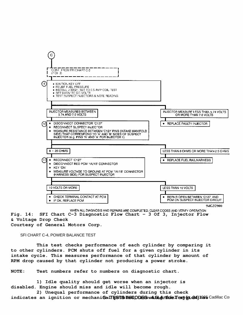
Fig. 14: SFI Chart C-3 Diagnostic Flow Chart - 3 Of 3, Injector Flow& Voltage Drop CheckCourtesy of General Motors Corp.
SFI CHART C-4, POWER BALANCE TEST
This test checks performance of each cylinder by comparing itto other cylinders. PCM shuts off fuel for a given cylinder in itsintake cycle. This measures performance of that cylinder by amount ofRPM drop caused by that cylinder not producing a power stroke.
NOTE: Test numbers refer to numbers on diagnostic chart.
1) Idle quality should get worse when an injector isdisabled. Engine should miss and idle will become rough. 2) Unequal performance of cylinders during this checkindicates an ignition or mechanical problem, assuming fuel system has

G - TESTS W/CODES - 4.6L
already been checked. Diagnose ignition system before checking for anengine mechanical problem. 3) If fuel system and power balance checks okay, check EGR,EVAP or PCV system for possible problem.
Fig. 15: SFI Chart C-4 Schematic, Power Balance TestCourtesy of General Motors Corp.

G - TESTS W/CODES - 4.6LArticle Text (p. 36)1995 Cadillac ConcoursFor Ace Mechanics 123 Main Street San Diego Ca 92126
Fig. 16: SFI Chart C-4 Diagnostic Flow Chart - 1 Of 2, Power BalanceTestCourtesy of General Motors Corp.
Fig. 17: SFI Chart C-4 Diagnostic Flow Chart - 2 Of 2, Power BalanceTestCourtesy of General Motors Corp.
SFI CHART C-5, FUEL LEAK/ODOR CHECK

G - TESTS W/CODES - 4.6LArticle Text (p. 37)1995 Cadillac Concours
This procedure provides a means of identifying a fuel systemcomponent that is causing a leak. This check also provides informationon how to diagnose a fuel odor condition.
NOTE: Test numbers refer to numbers on diagnostic chart.
1) Vehicle should be operated under same conditions as whenleak/odor occurred. 2) Nylon fuel lines are not repairable and must be replaced. 3) EVAP system problem or a rich engine operation may cause afuel odor condition.
Fig. 18: SFI Chart C-5 Diagnostic Flow Chart, Fuel Leak/Odor CheckCourtesy of General Motors Corp.
SFI CHART C-6, IDLE SPEED CONTROL (ISC) CHECK
This test verifies ISC motor operation and checks ISC plungeradjustment.
NOTE: Test numbers refer to numbers on diagnostic chart.
1) This checks for a high minimum air idle which could causea sail-on condition. High minimum air idle is okay if engine cannotstay running at minimum air idle. 2) Perform Code P030 diagnosis to identify cause of faultyISC motor. 3) This determines ISC authority. This is determined bycomparing minimum TP sensor value to the maximum ISC extend value. ISCauthority should be adjusted to 10-11 degrees of throttle angle. 4) TP sensor idle learn procedure must be performed after ISCplunger adjustment.

G - TESTS W/CODES - 4.6LArticle Text (p. 38)1995 Cadillac ConcoursFor Ace Mechanics 123 Main Street San Diego Ca 92126
Fig. 19: SFI Chart C-6 Schematic, Idle Speed Control (ISC) CheckCourtesy of General Motors Corp.

G - TESTS W/CODES - 4.6LArticle Text (p. 39)1995 Cadillac ConcoursFor Ace Mechanics 123 Main Street San Diego Ca 92126
Fig. 20: SFI Chart C-6 Diagnostic Flow Chart, Idle Speed Control(ISC) CheckCourtesy of General Motors Corp.
POWERTRAIN CHARTS
POWERTRAIN CHART 1, POWERTRAIN SYSTEM CHECK
POWERTRAIN SYSTEM CHECK is an organized approach toidentifying a computer-controlled electronics problem. Understandingchart and using it correctly will reduce diagnostic time and preventunnecessary parts replacement. Use POWERTRAIN SYSTEM CHECK to begin diagnosis if any
G - TESTS W/CODES - 4.6L
customer complaint does not directly relate to a specific subsystem.If Malfunction Indicator Light (MIL) fails to illuminate duringcranking, problem could be in PCM power supply circuit. POWERTRAINSYSTEM CHECK will direct technician to an appropriate diagnosticchart, test procedure in appropriate article. If DIC panel display is not operating properly, PCM self-diagnostics mode cannot be used and POWERTRAIN SYSTEM CHECK willdirect technician to an appropriate diagnostic chart, test procedurein appropriate article. If a trouble code is identified by PCM computer system self-diagnostics mode, problem can be corrected following appropriatenumbered code charts. If no trouble code has been identified,POWERTRAIN SYSTEM CHECK will direct technician to an appropriatediagnostic chart, test procedure in appropriate article.
NOTE: Test numbers refer to numbers on diagnostic chart.
1) Checks if system will enter diagnostics. If diagnosticscannot be entered or displays are blank, problem exists in IPC orrelated circuit. Diagnose system as follows:
* Turn ignition on. Using a DVOM connected to ground, backprobe IPC connector cavities A1, A2, C12 and C14. Reading should be greater than 10 volts. If voltage reading on one or more terminal is not as specified, repair open or short in related circuit. If voltage reading is not as specified on all terminals, check charging system. * If all of voltage readings are correct, turn ignition off. Disconnect IPC connectors (Black and White). Measure resistance between ground and IPC connector cavities A5 and C16. If any measurement is greater than one ohm, repair affected circuit or check/repair ground. If both circuits are less than, reconnect IPC connectors. * Turn ignition on. Using a DVOM connected to ground, backprobe IPC connector cavity B2. If reading is 14 volts or greater, check IPC connectors for good terminal contact. If contacts are okay and diagnostics still cannot be entered, replace IPC. * If reading is less than 14 volts, disconnect radio head and measure voltage at IPC connector terminal B2. If reading is 14 volts or greater, replace radio head. If reading is less than 14 volts, disconnect IPC connector. * Check continuity between IPC connector terminal B2 and ground. If continuity is present, repair short in circuit. If continuity is not present, replace IPC assembly.
2) Checks to see if IPC is able to communicate with PCM. IfIPC is unable to communicate with PCM, Code I034 will set or NO PCM

G - TESTS W/CODES - 4.6L
DATA message will be displayed when diagnostics are used. 3) MIL should be on when vehicle is in diagnostic mode. 4) Checks if powertrain system is operational. 5) Checks if PCM codes are present. 6) MIL should be off if codes are not present. 7) Checks if known customer complaint is causing problem. 8) If complaint is not in customer complaint list, performsystem check applying to situation.
Fig. 21: Powertrain Chart 1 Schematic, Powertrain System CheckCourtesy of General Motors Corp.

G - TESTS W/CODES - 4.6LArticle Text (p. 42)1995 Cadillac ConcoursFor Ace Mechanics 123 Main Street San Diego Ca 92126
Fig. 22: Powertrain Chart 1 Diagnostic Flow Chart, Powertrain SystemCheckCourtesy of General Motors Corp.

G - TESTS W/CODES - 4.6LArticle Text (p. 43)1995 Cadillac Concours
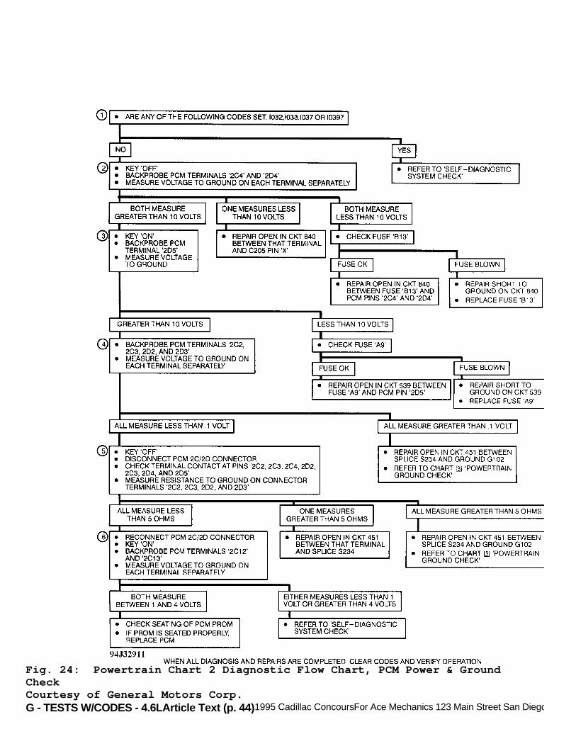
POWERTRAIN CHART 2, PCM POWER & GROUND CHECK
Battery voltage is present at all times at PCM terminals No.2C4 and 2D4 through circuit No. 840 from engine compartment fuseblock, fuse B13. PCM is also fed IGN 1 (hot in run, bulb test andstart) at PCM terminal No. 2D5 through circuit No. 539 from enginecompartment fuse block, fuse A9. PCM needs both battery and IGN 1voltage to operate. PCM grounding points are at PCM terminals No. 2C2, 2C3, 2D2and 2D3 through circuit No. 451 to ground (circuit G102).
NOTE: Test numbers refer to numbers on diagnostic chart.
1) This test checks for data line codes that would indicatethat entire data line is down. 2) Checks for battery voltage on circuit No. 840. If voltageis measured at one terminal and not other, check circuit No. 840 foran open to connector C205. If voltage is not measured at eitherterminal, check fuse B13 and circuit No. 840 to C205 for an open. 3) Checks circuit No. 539 and fuse A9 for open. 4) Checks for open circuit at circuit No. 451. If voltagemeasures greater than .1 volt on 1-3 wires, repair open to circuitS234. If voltage measures greater than .1 volt on all 4 wires, repairopen from circuit S234 to G102 (ground). 5) Checks for an open in circuit No. 451 or inside PCM. 6) Checks if data line is open or shorted to ground orvoltage, causing a PCM problem.
Fig. 23: Powertrain Chart 2 Schematic, PCM Power & Ground CheckCourtesy of General Motors Corp.
G - TESTS W/CODES - 4.6LArticle Text (p. 44)1995 Cadillac ConcoursFor Ace Mechanics 123 Main Street San Diego Ca 92126
Fig. 24: Powertrain Chart 2 Diagnostic Flow Chart, PCM Power & GroundCheckCourtesy of General Motors Corp.

G - TESTS W/CODES - 4.6LArticle Text (p. 45)1995 Cadillac ConcoursFor Ace Mechanics 123 Main Street San Diego Ca 92126
POWERTRAIN CHART 3, POWERTRAIN GROUND CHECK
Circuit G401 is ground location for fuel pump. Circuit G100is battery ground. Circuit G102 is ground for all powertrainelectronics, including PCM. Loose or poor ground connections may cause a variety ofproblems, including flickering telltales, PCM codes and severaldriveability problems. POWERTRAIN GROUND CHECK should be performedwhen referred to by other diagnostics or when erratic or intermittentproblem is present. These 3 vehicle grounds are essential for proper powertrainsystem operation. They are:
* Circuit G100, located near battery. * Circuit G102, located on right rear corner of engine block. * Circuit G401, located on front side of left rear seat diagonal brace.
Fig. 25: Powertrain Chart 3 Schematic, Powertrain Ground CheckCourtesy of General Motors Corp.

G - TESTS W/CODES - 4.6LArticle Text (p. 46)1995 Cadillac ConcoursFor Ace Mechanics 123 Main Street San Diego Ca 92126
Fig. 26: Powertrain Chart 3 Diagnostic Flow Chart, Powertrain GroundCheckCourtesy of General Motors Corp.
G - TESTS W/CODES - 4.6LArticle Text (p. 47)1995 Cadillac Concours
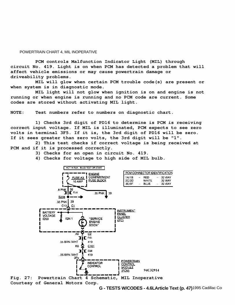
POWERTRAIN CHART 4, MIL INOPERATIVE
PCM controls Malfunction Indicator Light (MIL) throughcircuit No. 419. Light is on when PCM has detected a problem that willaffect vehicle emissions or may cause powertrain damage ordriveability problems. MIL will glow when certain PCM trouble code(s) are present orwhen system is in diagnostic mode. MIL light will not glow when ignition is on and engine is notrunning or when engine is running and no PCM code are current. Somecodes are stored without activating MIL light.
NOTE: Test numbers refer to numbers on diagnostic chart.
1) Checks 3rd digit of PD16 to determine is PCM is receivingcorrect input voltage. If MIL is illuminated, PCM expects to see zerovolts in terminal 3F5. If it is, the 3rd digit of PD16 will be zero.If it sees greater than zero volts, the 3rd digit will be "1". 2) This test checks if correct voltage is being received atPCM and if it is processed correctly. 3) Checks for an open in circuit No. 419. 4) Checks for voltage to high side of MIL bulb.
Fig. 27: Powertrain Chart 4 Schematic, MIL InoperativeCourtesy of General Motors Corp.

G - TESTS W/CODES - 4.6LArticle Text (p. 48)1995 Cadillac ConcoursFor Ace Mechanics 123 Main Street San Diego Ca 92126
Fig. 28: Powertrain Chart 4 Diagnostic Flow Chart, MIL InoperativeCourtesy of General Motors Corp.
POWERTRAIN CHART 5, MIL ON (NO CODES PRESENT)
PCM controls MIL through circuit No. 419. Light willilluminate when PCM detects a problem that will affect vehicleemissions, or cause powertrain damage or driveability problems.MIL will illuminate when certain PCM trouble codes are present or whensystem is in diagnostic mode. MIL will not illuminate when ignition is on and engine is notrunning or when engine is running and no PCM codes are current. Somecodes are stored without activating MIL.
NOTE: Test numbers refer to numbers on diagnostic chart.
1) With ignition on, MIL should be off. Check if any otherfault is present. 2) Check for diagnostic trouble code(s) causing MIL to
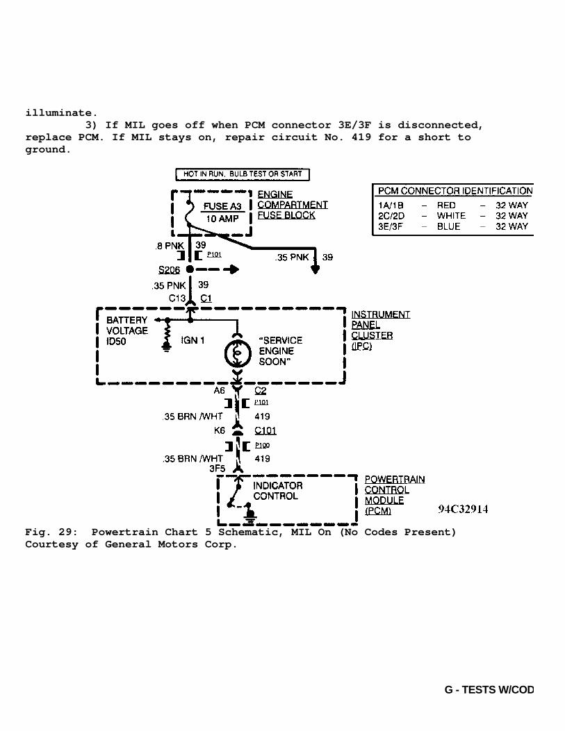
G - TESTS W/CODES - 4.6L
illuminate. 3) If MIL goes off when PCM connector 3E/3F is disconnected,replace PCM. If MIL stays on, repair circuit No. 419 for a short toground.
Fig. 29: Powertrain Chart 5 Schematic, MIL On (No Codes Present)Courtesy of General Motors Corp.

G - TESTS W/CODES - 4.6LArticle Text (p. 50)1995 Cadillac ConcoursFor Ace Mechanics 123 Main Street San Diego Ca 92126
Fig. 30: Powertrain Chart 5 Diagnostic Flow Chart, MIL On (No CodesPresent)Courtesy of General Motors Corp.
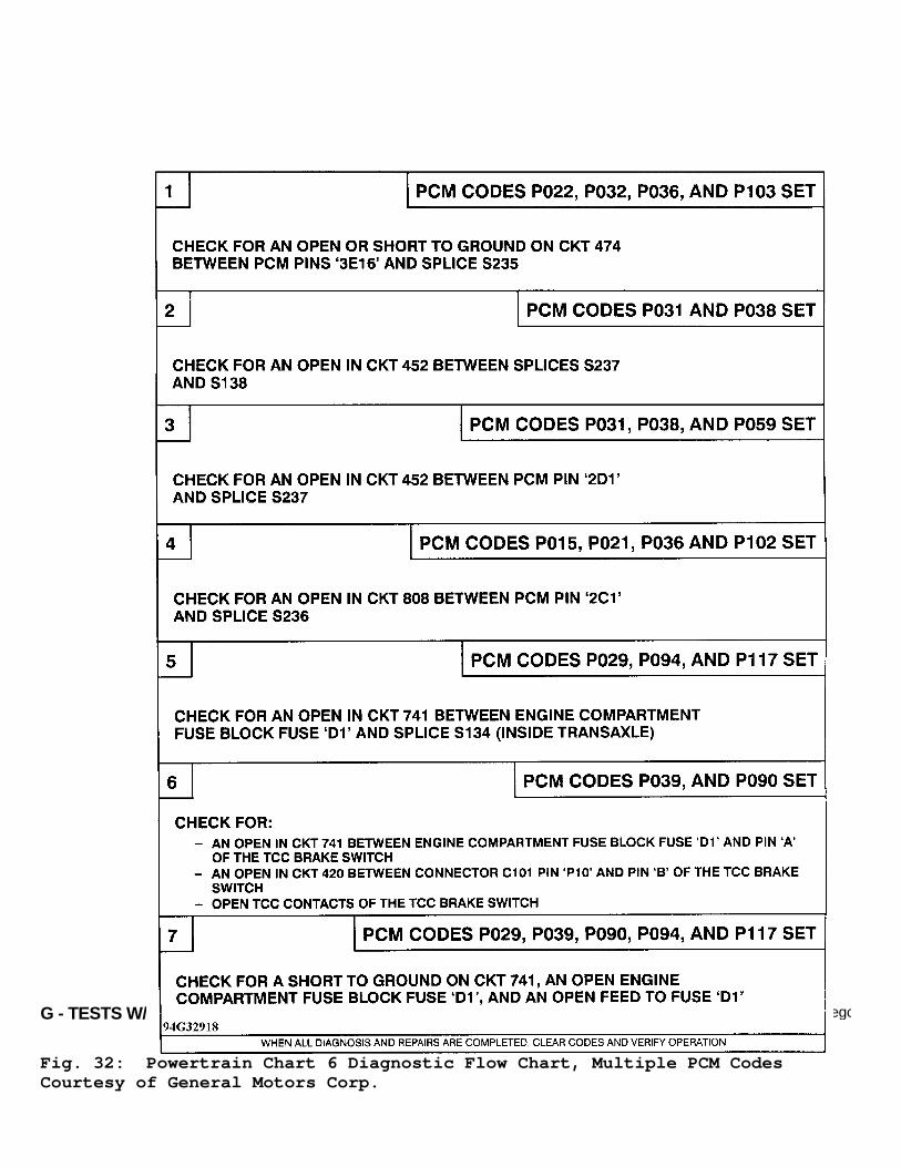
POWERTRAIN CHART 6, MULTIPLE PCM CODES
Some powertrain components share common feeds and returns.Certain failures of these circuits will cause multiple codes to set.Flow chart indicates groups of codes set by failure of common feedsand/or returns. If all codes in a group are set, perform diagnosislisted in that box. If all codes in a group are not set, diagnoselowest code number first.
NOTE: Test numbers refer to numbers on diagnostic chart.
1) Circuit No. 474 is 5-volt feed from PCM to MAP sensor, TPsensor, EGR valve and BBV sensor. An open or short to ground incircuit No. 474 between PCM terminal 3E16 and circuit S235 will causeCodes P022, P032, P036 and P103 to set. 2) Circuit No. 452 is sensor return to PCM from IAT and MAPsensors. An open in circuit No. 452 between circuits S237 and S138will cause Codes P031 and P038 to set. 3) Circuit No. 452 is sensor return to PCM from IAT sensor,MAP sensor and transaxle temperature sensor. An open in circuit No.

G - TESTS W/CODES - 4.6L
452 between circuit S237 and PCM terminal 2D1 will cause Codes P031,P038 and P059 to set. 4) Circuit No. 808 is sensor return to PCM from EGR valve,ECT sensor, BBV sensor and TP sensor. An open in circuit No. 808 andS236 and PCM will cause Codes P015, P021, P036 and P102 to set. 5) Circuit No. 741 is battery feed from fuse D1 (enginecompartment fuse block) to transaxle solenoids "A" and "B". An open incircuit No. 741 will cause Codes P029, P094 and P117 to set. 6) Circuit No. 741 is battery feed from fuse D1 (enginecompartment fuse block) to TCC brake switch which feeds the TCCthrough circuit No. 420. An open in circuits No. 741 and 420 or anopen in TCC contacts of TCC brake switch will cause Codes P039 andP090 to set. 7) Circuit No. 741 is battery feed for transaxle shiftsolenoids "A" and "B", TCC brake switch and TCC. A short to ground oncircuit No. 741, an open fuse D1 or an open feed to fuse D1 will causeCodes P029, P039, P090, P094 and P117 to set.
Fig. 31: Powertrain Chart 6 Schematic, Multiple PCM CodesCourtesy of General Motors Corp.
G - TESTS W/CODES - 4.6LArticle Text (p. 52)1995 Cadillac ConcoursFor Ace Mechanics 123 Main Street San Diego Ca 92126
Fig. 32: Powertrain Chart 6 Diagnostic Flow Chart, Multiple PCM CodesCourtesy of General Motors Corp.
G - TESTS W/CODES - 4.6LArticle Text (p. 53)1995 Cadillac ConcoursFor Ace Mechanics 123 Main Street San Diego Ca 92126
POWERTRAIN CHART 7, REAR OXYGEN SENSOR DIAGNOSIS
PCM provides .45-volt reference signal to oxygen sensor oncircuit No. 1670. When warm, a properly operating oxygen sensor willdrive .45-volt reference signal lower, indicating a lean mixture orhigher, indicating a rich mixture. This signal will toggle from richto lean rapidly, at least one toggle every 2 seconds, if PCM is ingood control of air/fuel mixture. This chart is designed to be used after oxygen sensorcircuit and PCM operation have been verified through POWERTRAIN CHART1, POWERTRAIN SYSTEM CHECK and PCM diagnostic trouble code diagnosis. This chart should identify oxygen sensors that are open (notable to drive .45-volt reference signal) or shorted (sensor output isfixed high or low, due to contaminants or internal sensor faults).
NOTE: Test numbers refer to numbers on diagnostic chart.
1) With engine running and coolant at normal operatingtemperature (85øC or greater) and at fast idle, observe engine dataparameter PD33. Voltage should swing from less than .3 volt to greaterthan .6 volt. 2) With engine at fast idle, observe open/closed loop statuslight (AUTO indicator on CCC). If PCM switches system into closed loopoperation, oxygen sensor is okay. If PCM remains in open loopoperation and coolant temperature PD04 is greater than 185øF (85øC),replace oxygen sensor. 3) If voltage remains .3-.6 volt for a minimum of one minute,replace oxygen sensor and check cause of sensor contamination. 4) If there is no high voltage variation, check forintermittent sensor terminal contact or faulty sensor.

G - TESTS W/CODES - 4.6LArticle Text (p. 54)1995 Cadillac ConcoursFor Ace Mechanics 123 Main Street San Diego Ca 92126
Fig. 33: Powertrain Chart 7 Schematic, Rear Oxygen Sensor DiagnosisCourtesy of General Motors Corp.

G - TESTS W/CODES - 4.6LArticle Text (p. 55)1995 Cadillac ConcoursFor Ace Mechanics 123 Main Street San Diego Ca 92126
Fig. 34: Powertrain Chart 7 Diag. Flow Chart, Rear O2 SensorDiagnosisCourtesy of General Motors Corp.
POWERTRAIN CHART 8, FRONT OXYGEN SENSOR DIAGNOSIS
PCM provides .45-volt reference signal to oxygen sensor oncircuit No. 412. When warm, a properly operating oxygen sensor willdrive .45-volt reference signal lower, indicating a lean mixture orhigher, indicating a rich mixture. This signal will toggle from richto lean rapidly, at least one toggle every 2 seconds, if PCM is ingood control of air/fuel mixture. This chart is designed to be used after oxygen sensorcircuit and PCM operation have been verified through POWERTRAIN CHART1, POWERTRAIN SYSTEM CHECK and PCM diagnostic trouble code diagnosis. This chart should identify oxygen sensors that are open (notable to drive .45-volt reference signal) or shorted (sensor output isfixed high or low, due to contaminants or internal sensor faults).

G - TESTS W/CODES - 4.6LArticle Text (p. 56)1995 Cadillac ConcoursFor Ace Mechanics 123 Main Street San Diego Ca 92126
NOTE: Test numbers refer to numbers on diagnostic chart.
1) With engine running and coolant at normal operatingtemperature (85øC or greater) and at fast idle, observe engine dataparameter PD32. Voltage should swing from less than .3 volt to greaterthan .6 volt. 2) With engine at fast idle, observe open/closed loop statuslight (AUTO indicator on CCC). If PCM switches system into closed loopoperation, oxygen sensor is okay. If PCM remains in open loopoperation and coolant temperature PD04 is greater than 185øF (85øC),replace oxygen sensor. 3) If voltage remains .3-.6 volt for a minimum of one minute,replace oxygen sensor and check for cause of sensor contamination. 4) If there is no voltage variation, check sensor forintermittent terminal contact or faulty sensor.
Fig. 35: Powertrain Chart 8 Schematic, Front Oxygen Sensor DiagnosisCourtesy of General Motors Corp.

G - TESTS W/CODES - 4.6LArticle Text (p. 57)1995 Cadillac ConcoursFor Ace Mechanics 123 Main Street San Diego Ca 92126
Fig. 36: Powertrain Chart 8 Diag. Flow Chart, Front O2 SensorDiagnosisCourtesy of General Motors Corp.
PCM CODE CHARTS
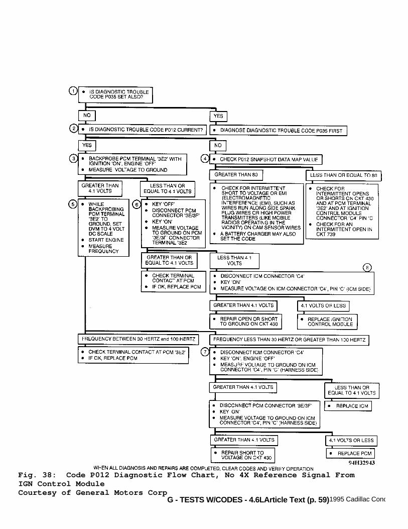
CODE P012, NO 4X REFERENCE SIGNAL FROM IGN CONTROL MODULE
PCM checks for cam pulses being received without 4X referencepulses. If PCM senses no reference pulses, engine will not startbecause fuel delivery system is triggered by pulses and Code P012 isset. Engine will start and run after an extended crank with CodeP012 set. This is because the 24X reference pulses are being receivedby PCM. PCM uses this signal for fuel control instead.
Test Conditions Codes P035 and P041 not set. Code P012 is testedanytime cam sensor signals are being received during engine crankingoperation.

G - TESTS W/CODES - 4.6LArticle Text (p. 58)1995 Cadillac ConcoursFor Ace Mechanics 123 Main Street San Diego Ca 92126
Failure Conditions If PCM does not receive 4X reference pulses for 4 secondswhile receiving cam reference pulses, Code P012 will set.
Action PCM turns on Malfunction Indicator Light (MIL).
NOTE: Test numbers refer to numbers on diagnostic chart.
1) Checks to see if Code P035 is present because a REF LOproblem can cause other ignition problems. 2) If Code P012 is current, the condition still exists andcan be diagnosed directly. If Code P012 is history, look at snapshotdata to determine conditions under which code was set. 3) Check for proper output of electronic ignition system. Ifvoltmeter reads 4.1 volts or greater, ignition control module is ableto produce 4X reference pulses. 4) Checks to see if Code P012 was set while vehicle wasrunning or not, if MAP value is 80 kPa or less, or if engine wasrunning when code was set. Stray cam pulses with ignition on, enginenot running can also cause a false Code P012 to set. 5) Checks for 4X reference pulses on circuit No. 430 fromignition control module to PCM. If PCM terminal No. 3E2 has beenbetween 30-100 Hertz, PCM is receiving 4X receiving pulses. 6) Checks if a faulty PCM is pulling the 4X signal low. 7) Checks for short to voltage on circuit No. 430. 8) Checks if ICM is providing proper reference signal to PCM.
Fig. 37: Code P012 Schematic, No 4X Reference Signal From IGN ControlModuleCourtesy of General Motors Corp
G - TESTS W/CODES - 4.6LArticle Text (p. 59)1995 Cadillac Concours
Fig. 38: Code P012 Diagnostic Flow Chart, No 4X Reference Signal FromIGN Control ModuleCourtesy of General Motors Corp

G - TESTS W/CODES - 4.6LArticle Text (p. 60)1995 Cadillac ConcoursFor Ace Mechanics 123 Main Street San Diego Ca 92126
CODE P013, REAR HEATED OXYGEN SENSOR NOT READY
PCM provides .45-volt reference signal to oxygen sensor oncircuit No. 1670. When oxygen sensor reaches operating temperature, itwill generate a counter voltage that will vary based on amount ofoxygen in exhaust. Rear oxygen sensor is located in manifold, beforecatalytic converter. A lean exhaust will generate a low voltage and cause .45-voltreference signal to decrease. A rich exhaust will generate a highervoltage and cause .45-volt reference signal to increase.Code P013 will set when oxygen sensor cannot respond under testconditions and generate a voltage greater or less than .45-voltreference. Code P013 will also set under following conditions: 1) Open in circuit No. 1670 or 1671. 2) Short to voltage on circuit No. 1670 or 1671. 3) Faulty oxygen sensor.
Test Conditions Codes P014, P015, P021, P022, P026 and P027 are not set.Coolant temperature greater than or equal to 180øF (82øC). TP sensorvalue of 5-25 degrees. Throttle switch open. RPM 800 or greater.
Failure Conditions Oxygen sensor voltage stays .307-.609 volt for more than 64seconds (not toggling).
Action PCM turns on MIL and closed loop is disabled. PCM enablescanister purge solenoid if Code P017 is set.
NOTE: Test numbers refer to numbers on diagnostic chart. See POWERTRAIN CHARTS for references to CHART 7.
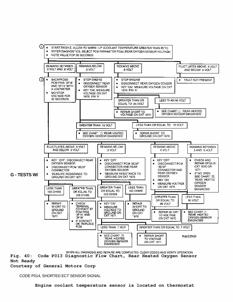
1) Voltage on PCM data parameter PD33 should fluctuate fromless than 0.3 volt to greater than 0.6 volt. If voltage remain greaterthan 0.6 volt, check circuit No. 1670 for short to voltage. If voltageremains less than 0.3 volt, check circuit No. 1670 for short toground. 2) Measuring voltage using voltmeter will isolatesensor/wiring problem from a PCM problem. If voltage fluctuates atgreater than 0.6 volt and less than 0.3 volt, fault is with PCM. Ifvoltage remains less than 0.3 volt, check circuit No. 1670 for shortto ground or circuit No. 1671 for short to voltage. If voltage remainsgreater than 0.6 volt, check circuit No. 1670 for short to voltage. Ifvoltage remains 0.3-0.6 volt, check circuits No. 1670 and 1671 for anopen.

G - TESTS W/CODES - 4.6LArticle Text (p. 61)1995 Cadillac ConcoursFor Ace Mechanics 123 Main Street San Diego Ca 92126
Fig. 39: Code P013 Schematic, Rear Heated Oxygen Sensor Not ReadyCourtesy of General Motors Corp
G - TESTS W/CODES - 4.6LArticle Text (p. 62)1995 Cadillac ConcoursFor Ace Mechanics 123 Main Street San Diego Ca 92126
Fig. 40: Code P013 Diagnostic Flow Chart, Rear Heated Oxygen SensorNot ReadyCourtesy of General Motors Corp
CODE P014, SHORTED ECT SENSOR SIGNAL
Engine coolant temperature sensor is located on thermostat

G - TESTS W/CODES - 4.6L
housing. ECT signal is on circuit No. 410. Sensor ground is on circuitNo. 808. As sensor temperature increases, resistance decreases. A highcoolant temperature will result in low signal voltage on circuit No.410. Code P014 sets because engine coolant temperature cannot begreater than 296øF (147øC) when intake air temperature is less than212øF (100øC).
Test Conditions Codes P037 and P038 are not set and intake air temperaturesensor value is less than or equal to 212øF (100øC).
Failure Conditions Coolant sensor value greater than or equal to 298øF (148øC)for 2 seconds.
Action PCM turns on MIL and uses IAT sensor value instead of coolantsensor value for all calculations during first 10 minutes ofoperation; it then uses a value of 194øF (90øC). Transaxle shiftadapts are maintained at current levels.
NOTE: Test numbers refer to numbers on diagnostic chart.
1) With ECT sensor or wiring shorted, PCM parameter PD04should indicate 148øC or greater. If PD04 does not indicate 148øC orgreater, sensor or wiring is not shorted. 2) Checks for shorted sensor or circuit No. 410. If parametervalue stays at 147øC or greater with sensor unplugged, short is incircuit No. 410 between terminal "B" and PCM terminal 1B5. 3) Check PCM connector. Fault is most likely at PCM connectoror PCM.

G - TESTS W/CODES - 4.6LArticle Text (p. 64)1995 Cadillac ConcoursFor Ace Mechanics 123 Main Street San Diego Ca 92126
Fig. 41: Code P014 Schematic, Shorted ECT Sensor SignalCourtesy of General Motors Corp
Fig. 42: Code P014 Diagnostic Flow Chart, Shorted ECT Sensor SignalCourtesy of General Motors Corp
G - TESTS W/CODES - 4.6LArticle Text (p. 65)1995 Cadillac ConcoursFor Ace Mechanics 123 Main Street San Diego Ca 92126
CODE P015, OPEN ECT SENSOR SIGNAL
Engine coolant temperature sensor is a 2-wire thermistor,whose resistance varies with temperature. Sensor signal is on circuitNo. 410. Sensor ground is on circuit No. 476. As sensor temperature increases, sensor resistance decreases.High coolant temperature will result in low signal voltage on circuitNo. 410. Code P015 sets because PCM assumes coolant temperature cannotbe -20øF (-29øC) or less when IAT is -9.4øF (-23øC) or greater.
Test Conditions Codes P037 and P038 not set and IAT sensor value greaterthan or equal to -9.4øF (-23øC).
Failure Conditions ECT sensor value is -20øF (-29øC) or less for 2 seconds.
Action PCM turns on MIL and uses IAT sensor value instead of ECTsensor value for all calculations during first 5 minutes of operation.After 5 minutes, PCM uses a value of 194øF (90øC). Transaxle shiftadapts are maintained at current levels.
NOTE: Test numbers refer to numbers on diagnostic chart.
1) If sensor or wiring is open, parameter PD04 shouldindicate -29øC or less. 2) This checks for open sensor signal in circuit No. 410 fromPCM to sensor connector. If parameter PD04 indicates 135-151øC withconnector shorted, circuits No. 410 and 808 are okay. 3) Checks for open in circuit No. 808 from sensor terminal"A" to ground splice. If shorting terminal "A" to ground causesparameter PD04 to indicate 135-151øC, an open in circuit No. 808exists. 4) This checks if PCM can recognize a short to ground or lowvoltage on terminal 1B5, coolant temperature signal. If groundingterminal 1B5 causes PD04 to indicate 135-151øC, circuit No. 410 fromPCM to ECT sensor is open.

G - TESTS W/CODES - 4.6LArticle Text (p. 66)1995 Cadillac ConcoursFor Ace Mechanics 123 Main Street San Diego Ca 92126
Fig. 43: Code P015 Schematic, Open ECT Sensor SignalCourtesy of General Motors Corp

G - TESTS W/CODES - 4.6LArticle Text (p. 67)1995 Cadillac ConcoursFor Ace Mechanics 123 Main Street San Diego Ca 92126
Fig. 44: Code P015 Diagnostic Flow Chart, Open ECT Sensor SignalCourtesy of General Motors Corp
CODE P016, ALTERNATOR VOLTAGE OUT OF RANGE
PCM monitors ignition feed voltage on circuit No. 539 to PCM.Code P016 sets when system voltage drops to less than 10 volts orincreases to greater than 16 volts with engine running at greater than500 RPM. If ignition voltage goes to zero volts (open circuit), enginewill not run since PCM does not have ignition signal.
Test Conditions Tested continuously.
Failure Conditions Engine speed at 500 RPM or greater. Ignition voltage to PCMless than 10 volts or more than 16 volts for 5.0 seconds.

G - TESTS W/CODES - 4.6LArticle Text (p. 68)1995 Cadillac ConcoursFor Ace Mechanics 123 Main Street San Diego Ca 92126
Action PCM turns on MIL. PCM turns off canister purge solenoid,disables cruise control, de-energizes TCC solenoid and disablestransaxle pressure control solenoid. PCM allows only 2nd gearoperation when any forward gear is selected. Transaxle shifts adaptsare maintained at current level. Garage shift adapts are maintained atcurrent levels.
NOTE: Test numbers refer to numbers on diagnostic chart.
1) This checks PCM data for parameters PD15 and ID50. Ifvoltages are within 0.5 volts of each other, a system problem mayexist. If not, find out why PCM is different. 2) This checks if PCM data PD15 is actually displaying systemvoltage.
Note On Intermittents A loose or faulty alternator terminal "L" connector maycause Code P016 to set intermittently.
Fig. 45: Code P016 Schematic, Alternator Voltage Out Of RangeCourtesy of General Motors Corp
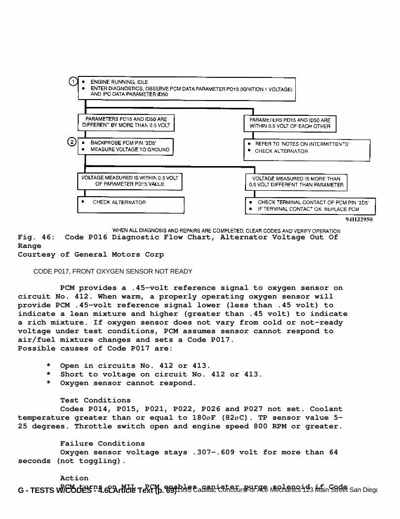
G - TESTS W/CODES - 4.6LArticle Text (p. 69)1995 Cadillac ConcoursFor Ace Mechanics 123 Main Street San Diego Ca 92126
Fig. 46: Code P016 Diagnostic Flow Chart, Alternator Voltage Out OfRangeCourtesy of General Motors Corp
CODE P017, FRONT OXYGEN SENSOR NOT READY
PCM provides a .45-volt reference signal to oxygen sensor oncircuit No. 412. When warm, a properly operating oxygen sensor willprovide PCM .45-volt reference signal lower (less than .45 volt) toindicate a lean mixture and higher (greater than .45 volt) to indicatea rich mixture. If oxygen sensor does not vary from cold or not-readyvoltage under test conditions, PCM assumes sensor cannot respond toair/fuel mixture changes and sets a Code P017.Possible causes of Code P017 are:
* Open in circuits No. 412 or 413. * Short to voltage on circuit No. 412 or 413. * Oxygen sensor cannot respond.
Test Conditions Codes P014, P015, P021, P022, P026 and P027 not set. Coolanttemperature greater than or equal to 180øF (82øC). TP sensor value 5-25 degrees. Throttle switch open and engine speed 800 RPM or greater.
Failure Conditions Oxygen sensor voltage stays .307-.609 volt for more than 64seconds (not toggling).
Action PCM turns on MIL. PCM enables canister purge solenoid if Code
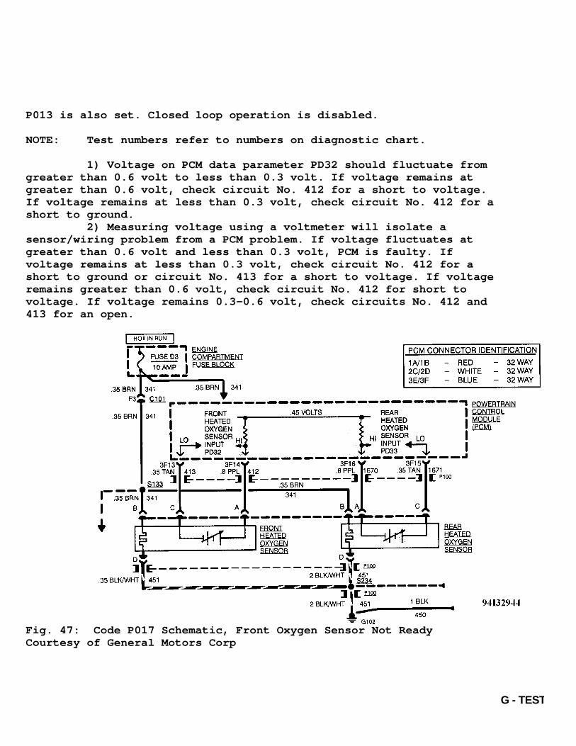
G - TESTS W/CODES - 4.6L
P013 is also set. Closed loop operation is disabled.
NOTE: Test numbers refer to numbers on diagnostic chart.
1) Voltage on PCM data parameter PD32 should fluctuate fromgreater than 0.6 volt to less than 0.3 volt. If voltage remains atgreater than 0.6 volt, check circuit No. 412 for a short to voltage.If voltage remains at less than 0.3 volt, check circuit No. 412 for ashort to ground. 2) Measuring voltage using a voltmeter will isolate asensor/wiring problem from a PCM problem. If voltage fluctuates atgreater than 0.6 volt and less than 0.3 volt, PCM is faulty. Ifvoltage remains at less than 0.3 volt, check circuit No. 412 for ashort to ground or circuit No. 413 for a short to voltage. If voltageremains greater than 0.6 volt, check circuit No. 412 for short tovoltage. If voltage remains 0.3-0.6 volt, check circuits No. 412 and413 for an open.
Fig. 47: Code P017 Schematic, Front Oxygen Sensor Not ReadyCourtesy of General Motors Corp

G - TESTS W/CODES - 4.6LArticle Text (p. 71)1995 Cadillac ConcoursFor Ace Mechanics 123 Main Street San Diego Ca 92126Fig. 48: Code P017 Diagnostic Flow Chart, Front Oxygen Sensor NotReadyCourtesy of General Motors Corp
CODE P019, SHORTED FUEL PUMP FEEDBACK SIGNAL

G - TESTS W/CODES - 4.6LArticle Text (p. 72)1995 Cadillac Concours
PCM monitors fuel pump feedback voltage for 6 seconds afterignition is turned on without engine being cranked. Fuel pump relaywill be energized for 2 seconds and then de-energized. If voltage onfuel pump feedback does not drop to less than 7 volts during first 4seconds after ignition is turned on (engine off), Code P019 will set,indicating voltage on circuit No. 120 with fuel pump relay de-energized.
Test Conditions Codes P012, P014 and P015 not set. Coolant temperature at122øF (50øC) or greater. No 4X reference pulses detected sinceignition was turned on (engine not cranked).
Failure Conditions Fuel pump feedback voltage remains greater than or equal to 7volts for 6 seconds (fuel pump relay never de-energized).
Action PCM turns on SERVICE VEHICLE SOON message.
NOTE: Test numbers refer to numbers on diagnostic chart.
1) With ignition on, engine off, fuel pump should not berunning and fuel pump feedback (PCM parameter PD10) should be zerovolts. If PD10 shows voltage greater than 7 volts, repair circuit No.120. 2) This checks for shorted oil pressure switch. 3) This checks for shorted fuel pump relay. 4) This checks for voltage on circuit No. 120 at PCM. 5) This checks for proper control of fuel pump relay by PCM.
Note On Intermittents Probe fuel pump test point using a voltmeter to ground. Turnignition on, and observe voltmeter. Voltmeter should indicate batteryvoltage for 2 seconds and then drop to zero. If voltage reading staysat battery voltage for longer than 2 seconds, check for sticking fuelpump relay contacts. Repeat test several times. Continue probing fuelpump test point to ground. Start engine, and then turn it off. Voltageshould immediately drop to zero. If voltage does not immediately dropto zero, check oil pressure switch contacts.
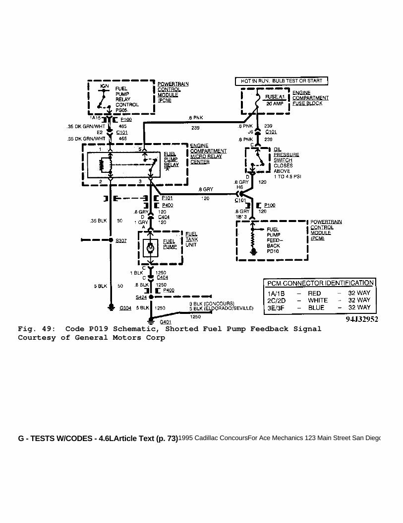
G - TESTS W/CODES - 4.6LArticle Text (p. 73)1995 Cadillac ConcoursFor Ace Mechanics 123 Main Street San Diego Ca 92126
Fig. 49: Code P019 Schematic, Shorted Fuel Pump Feedback SignalCourtesy of General Motors Corp

G - TESTS W/CODES - 4.6LArticle Text (p. 74)1995 Cadillac ConcoursFor Ace Mechanics 123 Main Street San Diego Ca 92126
Fig. 50: Code P019 Diagnostic Flow Chart, Shorted Fuel Pump FeedbackSignalCourtesy of General Motors Corp
CODE P020, OPEN FUEL PUMP CIRCUIT
Fuel pump receives power from circuit No. 120 through eitherthe fuel pump relay or oil pressure switch. PCM energizes fuel pumprelay for 2 seconds after key is turned on. Fuel pump is then turnedoff if no 4X reference pulses are received. The oil pressure switch isprovided as a backup to fuel pump relay enabling engine to start when

G - TESTS W/CODES - 4.6L
fuel pump relay fails. Code P020 is set when PCM sees fuel pump is notenergized (zero volts on feedback circuit) with engine cranking orrunning. PCM code is designed to detect a fuel pump relay fault (relaynot powering fuel pump).
Test Conditions Engine speed greater than or equal to 24 RPM.
Failure Conditions Fuel pump feedback voltage less than or equal to 2 volts for1.3 seconds or more.
Action PCM turns on SERVICE VEHICLE SOON light.
NOTE: Test numbers refer to numbers on diagnostic chart.
1) Checks for engine to start with fuel pump powered throughfuel pump relay. If engine does not start, proceed to CODE P020 (2 OF3). 2) Checks circuit No. 120 for open or if no fault code ispresent. 3) Checks for open in circuit No. 239 from fuse to fuel pumprelay terminal No. 5. 4) Checks for open in circuit No. 50 to fuel pump relayterminal No. 5. 5) Checks if fuel pump will run to isolate a fuel pumpcontrol problem from a fuel pump problem. 6) If greater than or equal to 10 volts is measured, fuelpump relay circuit is okay. Fuel pump relay is faulty. 7) Checks for open in circuit No. 120 from fuel pump relay tofuel pump. 8) Checks for proper control of fuel pump relay by PCM. 9) Checks for an open in circuit No. 1250 (fuel pump ground). 10) Checks circuit No. 239 for short to ground. 11) Isolates when circuit No. 120 is shorted to ground. 12) Checks circuit No. 120 for short to ground between oilpressure switch and PCM. 13) Checks fuel pump harness for short to ground. If harnessis okay, check circuit No. 120 from fuel pump relay terminal No. 3 forshort to ground.

G - TESTS W/CODES - 4.6LArticle Text (p. 76)1995 Cadillac ConcoursFor Ace Mechanics 123 Main Street San Diego Ca 92126
Fig. 51: Code P020 Schematic, Open Fuel Pump CircuitCourtesy of General Motors Corp

G - TESTS W/CODES - 4.6LArticle Text (p. 77)1995 Cadillac ConcoursFor Ace Mechanics 123 Main Street San Diego Ca 92126
Fig. 52: Code P020 Diagnostic Flow Chart - 1 Of 3, Open Fuel PumpCircuitCourtesy of General Motors Corp

G - TESTS W/CODES - 4.6LArticle Text (p. 78)1995 Cadillac ConcoursFor Ace Mechanics 123 Main Street San Diego Ca 92126
Fig. 53: Code P020 Diagnostic Flow Chart - 2 Of 3, Open Fuel PumpCircuitCourtesy of General Motors Corp
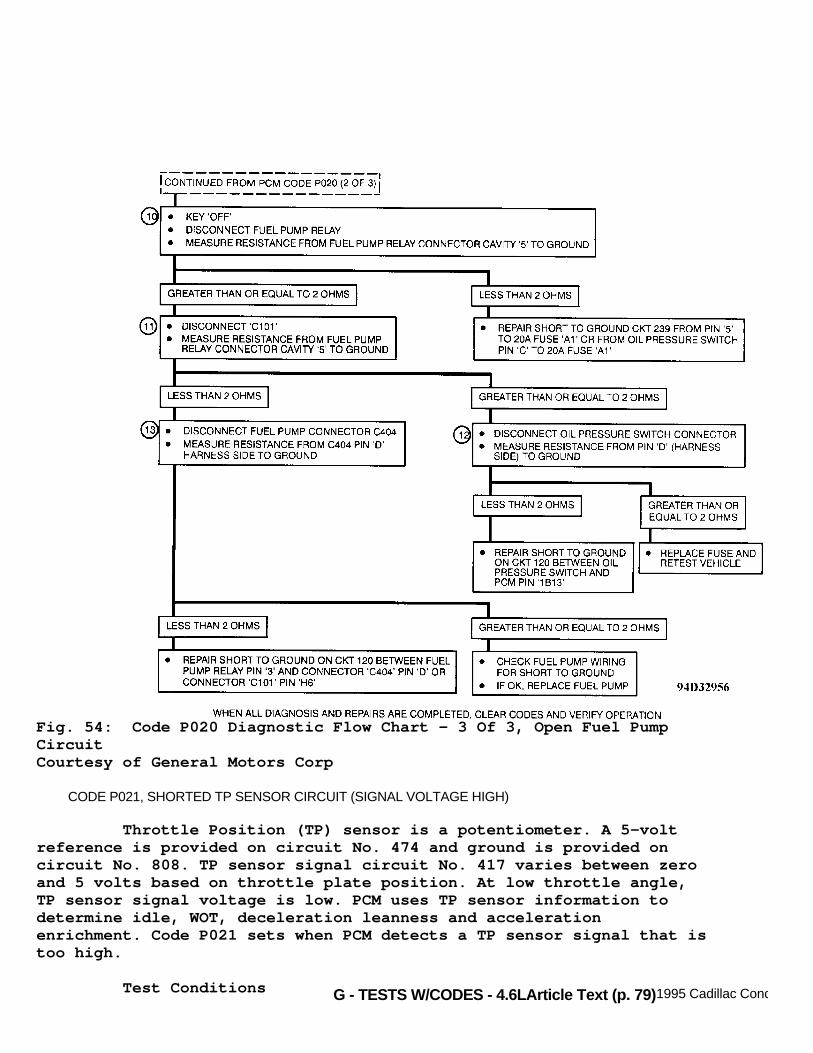
G - TESTS W/CODES - 4.6LArticle Text (p. 79)1995 Cadillac Concours
Fig. 54: Code P020 Diagnostic Flow Chart - 3 Of 3, Open Fuel PumpCircuitCourtesy of General Motors Corp
CODE P021, SHORTED TP SENSOR CIRCUIT (SIGNAL VOLTAGE HIGH)
Throttle Position (TP) sensor is a potentiometer. A 5-voltreference is provided on circuit No. 474 and ground is provided oncircuit No. 808. TP sensor signal circuit No. 417 varies between zeroand 5 volts based on throttle plate position. At low throttle angle,TP sensor signal voltage is low. PCM uses TP sensor information todetermine idle, WOT, deceleration leanness and accelerationenrichment. Code P021 sets when PCM detects a TP sensor signal that istoo high.
Test Conditions

G - TESTS W/CODES - 4.6LArticle Text (p. 80)1995 Cadillac ConcoursFor Ace Mechanics 123 Main Street San Diego Ca 92126
Engine speed 25-3000 RPM.
Failure Conditions TP sensor value greater than or equal to 85 degrees for 0.1second.
Action PCM turns on MIL, disables TCC and transaxle pressurecontrol. PCM sets TP sensor equal to 13 degrees when TP sensor is openand 6 degrees when TP sensor is closed. PCM freezes transaxle incurrent gear.
NOTE: Test numbers refer to numbers on diagnostic chart.
1) If TP sensor or wiring is shorted, data parameter PD01will read 85 or greater. 2) Checks for shorted TP sensor or wiring. If data valuestays greater than -7 with TP sensor disconnected, check for problemin wiring. 3) Check for open in circuit No. 808 between TP sensor andPCM. An open in circuit No. 808 will result in high TP sensor signalwhenever TP sensor is connected.
Fig. 55: Code P021 Schematic, Shorted TP Sensor Circuit (SignalVoltage High)Courtesy of General Motors Corp

G - TESTS W/CODES - 4.6LArticle Text (p. 81)1995 Cadillac Concours
Fig. 56: Code P021 Diagnostic Flow Chart, Shorted TP Sensor Circuit(Signal Voltage High)Courtesy of General Motors Corp
CODE P022, OPEN TP SENSOR CIRCUIT (SIGNAL VOLTAGE LOW)
TP sensor is a potentiometer. A 5-volt reference is providedon circuit No. 474 and ground is provided on circuit No. 808. TPsensor signal circuit No. 417 varies between zero and 5 volts based onthrottle plate position. At low throttle angle, TP sensor signalvoltage is low. PCM uses TP sensor information to determine idle, WOT,deceleration leanness and acceleration enrichment. Code P022 sets whenPCM detects a TP sensor signal that is too low.
Test Conditions Engine speed at least 600 RPM.
Failure Conditions TP sensor value less than -5 degrees for one second.
Action

G - TESTS W/CODES - 4.6LArticle Text (p. 82)1995 Cadillac ConcoursFor Ace Mechanics 123 Main Street San Diego Ca 92126
PCM turns on MIL and disables TCC. PCM sets TP sensor equalto 13 degrees when throttle switch is open and 6 degrees when throttleswitch is closed. PCM freezes transaxle in current gear.
NOTE: Test numbers refer to numbers on diagnostic chart.
1) If Code P032, P036 and P103 are also present, checkcircuit No. 474 for open or short to ground. TP sensor and MAP sensorshare 5-volt reference signal. 2) With TP sensor or wiring open, PCM data parameter PD01will read -5 or less. 3) Checks for open TP sensor or circuit. If data value staysless than 85 with TP sensor terminals "A" and "C" jumpered together,problem is in wiring. 4) Voltage should be greater than 0.5 volt if circuit No. 474is not open or shorted to ground. 5) Checks to see if circuit No. 474 is open or if circuit No.417 is shorted to ground. 6) Checks if signal is reaching PCM. If signal is reachingPCM, fault is in PCM.
Fig. 57: Code P022 Schematic, Open TP Sensor Circuit (Signal VoltageLow)Courtesy of General Motors Corp

G - TESTS W/CODES - 4.6LArticle Text (p. 83)1995 Cadillac ConcoursFor Ace Mechanics 123 Main Street San Diego Ca 92126
Fig. 58: Code P022 Diagnostic Flow Chart, Open TP Sensor Circuit(Signal Voltage Low)Courtesy of General Motors Corp
CODE P023, IGNITION CONTROL CIRCUIT PROBLEM
Test Conditions (Crank) By-pass line low (zero volts) and at least 2 reference pulseshave been received by PCM.
Failure Conditions (Crank) No ignition pulses detected in circuit No. 423.
Test Conditions (Run) By-pass line high (5 volts) and at least 2 reference pulses

G - TESTS W/CODES - 4.6L
have been received by PCM.
Failure Conditions (Run) No ignition control pulses detected on circuit No. 423.
Action PCM turns on MIL and will not enable spark timing control.Engine will start and run on base timing. PCM disables EGR solenoid.Transaxle shift adapts are maintained at current levels.
NOTE: Test numbers refer to numbers on diagnostic chart.
1) Checks if Code P035 is set. A REF LO problem can causeother ignition problems. 2) Checks if Code P023 was set during engine crank or whileengine was running. 3) Checks for short to voltage on circuit No. 424. Checks ifPCM failure is causing ignition control system into by-pass sparkcontrol when it should not be. 4) Checks for open in circuit No. 423 to see if ignitioncontrol pulses are reaching ignition control module or if pulses arereaching ignition control module but ignition control module is notreacting. 5) Checks for short to voltage in circuit No. 424. 6) Checks if by-pass control is being sent by PCM to ignitioncontrol module. If by-pass control is being sent, voltage will begreater than 4.1 volts. 7) Checks if by-pass control being sent by PCM is beingreceived by ignition control module. If circuit No. 424 is good,resistance will be less than 5 ohms. 8) Checks if PCM is providing proper signal to ICM. If PCMterminal 3F3 has 30-100 Hertz, PCM is not at fault. 9) Checks if PCM can produce proper ignition control pulses.If maximum voltage exceeds 3.7 volts, PCM is okay and ICM is at fault. 10) Checks circuit No. 424 for short to ground. 11) Checks if ICM is able to recognize a by-pass signal. Ifit does, Code P023 will not set again. If Code P023 resets, the ICM isfaulty. If does not reset, PCM is faulty. 12) Checks if ICM is causing incorrect voltage or if PCM issupplying incorrect signal.

G - TESTS W/CODES - 4.6LArticle Text (p. 85)1995 Cadillac ConcoursFor Ace Mechanics 123 Main Street San Diego Ca 92126
Fig. 59: Code P023 Schematic, Ignition Control Circuit ProblemCourtesy of General Motors Corp

G - TESTS W/CODES - 4.6LArticle Text (p. 86)1995 Cadillac ConcoursFor Ace Mechanics 123 Main Street San Diego Ca 92126
Fig. 60: Code P023 Diagnostic Flow Chart - 1 Of 2, Ignition ControlCircuit ProblemCourtesy of General Motors Corp

G - TESTS W/CODES - 4.6LArticle Text (p. 87)1995 Cadillac Concours
Fig. 61: Code P023 Flow Chart - 2 Of 2, Ignition Control CircuitProblemCourtesy of General Motors Corp

G - TESTS W/CODES - 4.6LArticle Text (p. 88)1995 Cadillac Concours
CODE P024, VEHICLE SPEED SENSOR (VSS) CIRCUIT PROBLEM
VSS is a permanent magnet pulse generator mounted intransaxle. PCM receives unbuffered speed information VSS. Code P024sets if PCM detects vehicle speed of 5 MPH or less with transaxleinput speed (turbine speed) of 3000 RPM or greater for one secondwhile in any forward gear. To avoid any erratic cruise controloperation due to an intermittent problem, cruise control system isdisabled for the entire ignition cycle.
Test Conditions Codes P056 and P091 not set. Transaxle in Park or Neutral.Transaxle pressure switch indicating not in Reverse. Transaxle inputspeed sensor indicating 3000 RPM or greater.
Failure Conditions Vehicle speed at 5 MPH or less for one second.
Action PCM turns on MIL and disables Torque Converter Clutch (TCC)and cruise control for the entire ignition cycle. PCM will substitutea calculated vehicle speed based on transaxle input speed and thecurrent gear commanded (gear ratio). PCM freezes transaxle in currentgear and torque management is disabled.
NOTE: Test number refers to number on diagnostic chart.
1) If Code P025 is current, fault is present and can bediagnosed directly. If Code P025 is stored as history, refer to CodeP075 to diagnose fault. 2) VSS will generate a frequency of greater than zero Hertzwhen spun by hand. If it does, PCM is faulty. If it does not, checkcircuit or sensor for open or short.
Note On Intermittents Check for Electromagnetic Interference (EMI) induced oncircuits No. 400 and 401 by running them close to spark plug wires orhigh power transmitters (mobile radios) operating in vicinity.

G - TESTS W/CODES - 4.6LArticle Text (p. 89)1995 Cadillac ConcoursFor Ace Mechanics 123 Main Street San Diego Ca 92126
Fig. 62: Code P024 Schematic, VSS Circuit ProblemCourtesy of General Motors Corp

G - TESTS W/CODES - 4.6LArticle Text (p. 90)1995 Cadillac ConcoursFor Ace Mechanics 123 Main Street San Diego Ca 92126
Fig. 63: Code P024 Diagnostic Flow Chart, VSS Circuit ProblemCourtesy of General Motors Corp
CODE P025, 24X REFERENCE SIGNAL LOW
PCM checks for 4X reference pulses being received without 24Xreference pulses. Code P025 is set when engine is running and PCM isreceiving 4X reference pulses and 24X reference signal line is low for4 seconds.
Test Conditions Codes P035 and P041 are not set. A cam reference pulse wasreceived and engine speed at greater than 496 RPM but less than 1200RPM. Ignition control not in by-pass mode.

G - TESTS W/CODES - 4.6LArticle Text (p. 91)1995 Cadillac ConcoursFor Ace Mechanics 123 Main Street San Diego Ca 92126
Failure Conditions No 24X reference pulses received by PCM and the line is lowfor 4 seconds.
Action PCM turns on SERVICE VEHICLE SOON light message.
NOTE: Test numbers refer to numbers on diagnostic chart.
1) Checks to see if Code P035 is present because REF LOproblem can cause other ignition problems. 2) Checks ability of ignition control module to produce 24Xreference pulses. If system is operating correctly, reading will be200 Hertz or greater. 3) Checks to see if ICM is providing PCM the proper 24Xreference signal. 4) Checks for open or short to ground in circuit No. 647.
Fig. 64: Code P025 Schematic, 24X Reference Signal LowCourtesy of General Motors Corp
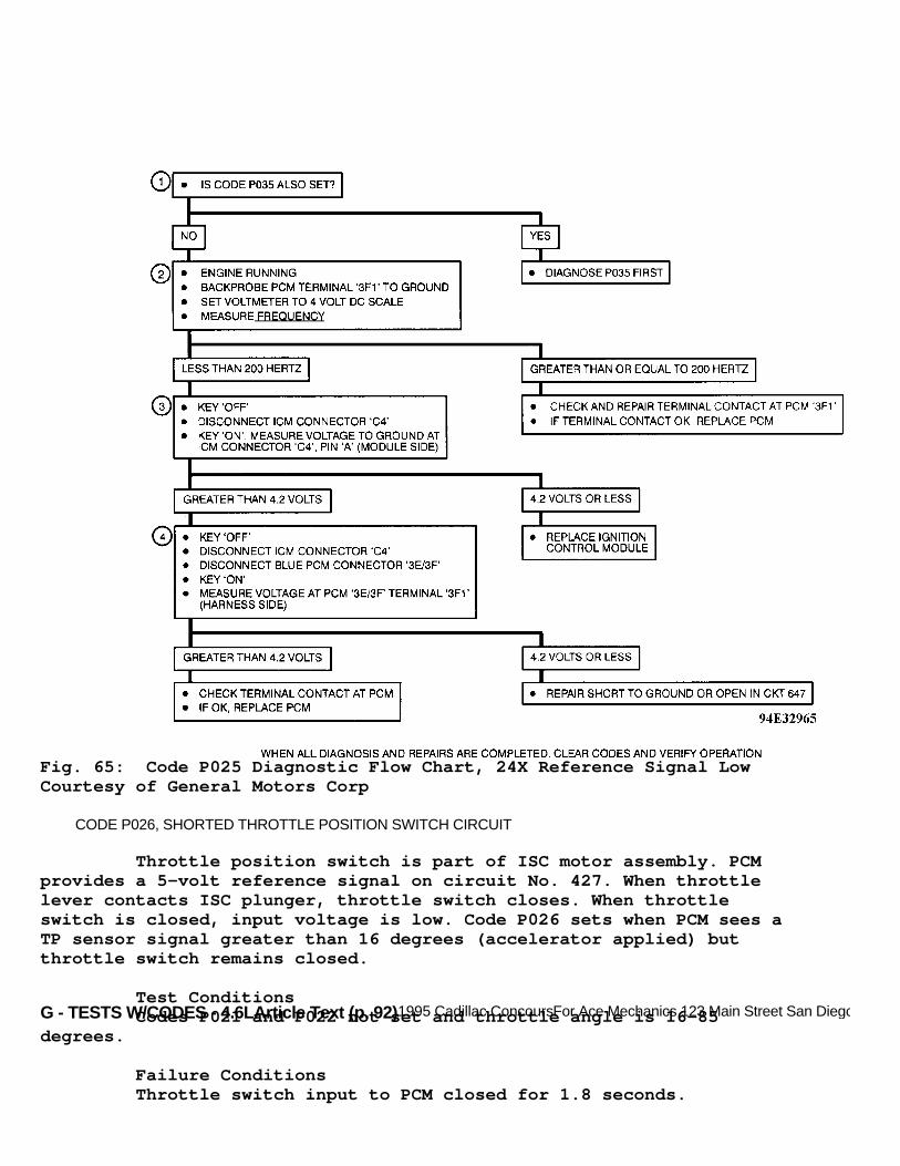
G - TESTS W/CODES - 4.6LArticle Text (p. 92)1995 Cadillac ConcoursFor Ace Mechanics 123 Main Street San Diego Ca 92126
Fig. 65: Code P025 Diagnostic Flow Chart, 24X Reference Signal LowCourtesy of General Motors Corp
CODE P026, SHORTED THROTTLE POSITION SWITCH CIRCUIT
Throttle position switch is part of ISC motor assembly. PCMprovides a 5-volt reference signal on circuit No. 427. When throttlelever contacts ISC plunger, throttle switch closes. When throttleswitch is closed, input voltage is low. Code P026 sets when PCM sees aTP sensor signal greater than 16 degrees (accelerator applied) butthrottle switch remains closed.
Test Conditions Codes P021 and P022 not set and throttle angle is 16-85degrees.
Failure Conditions Throttle switch input to PCM closed for 1.8 seconds.

G - TESTS W/CODES - 4.6L
Action PCM turns on MIL, disables EGR and assumes throttle switch isclosed if brakes are applied or if TP sensor position is less than orequal to 18 degrees. PCM also assumes open throttle when brakes areoff or TP sensor position is greater than 18 degrees. Garage shiftadapts are maintained at current levels.
NOTE: Test numbers refer to numbers on diagnostic chart.
1) PCM input PI72 should cycle from LO to HI to LO whenaccelerator is depressed and released. 2) If PCM input PI72 changes to HI when ISC motor isdisconnected, fault is with ISC motor. If PI72 still stays LO, checkcircuit No. 427 for short to ground. 3) Checks if circuit No. 427 is shorted to ground or if PCMis faulty.
Fig. 66: Code P026 Schematic, Shorted Throttle Position SwitchCircuitCourtesy of General Motors Corp

G - TESTS W/CODES - 4.6LArticle Text (p. 94)1995 Cadillac ConcoursFor Ace Mechanics 123 Main Street San Diego Ca 92126
Fig. 67: Code P026 Diagnostic Flow Chart, Shorted Throttle PositionSwitch CircuitCourtesy of General Motors Corp
CODE P027, OPEN THROTTLE POSITION SWITCH SIGNAL
Diagnostic test monitors ISC throttle position switch duringsome coast down and idle conditions with throttle position switch openand brake applied. Under these conditions, PCM commands ISC toretract, and monitors TP sensor for corresponding decrease in throttleposition. PCM sets Code P027 if it detects a decrease in throttleposition 2 times in succession, throttle is resting on ISC plunger andthrottle position should be closed.
Test Conditions Codes P021, P022 and P024 not set. Vehicle in coast downcondition. Throttle switch open, brakes applied, throttle angle 12degrees or less and engine speed at least 64 RPM greater than desired.At least 20 seconds have passed between brake applications or the lastISC motor pulse from PCM.
Failure Conditions PCM retracts ISC motor and sees a corresponding decrease inthrottle angle twice.

G - TESTS W/CODES - 4.6LArticle Text (p. 95)1995 Cadillac ConcoursFor Ace Mechanics 123 Main Street San Diego Ca 92126
Action PCM turns on MIL. EGR is disabled. Garage shift adapts aremaintained at current levels.
NOTE: Test numbers refer to numbers on diagnostic chart.
1) LO fan status light should cycle from ON to OFF to ON whenaccelerator is depressed and released. 2) Checks if fault is with throttle position switch. 3) Checks PCM's ability to recognize signal if circuit No.427 is open. 4) Checks if circuit No. 451 is open.
Note On Intermittents Code P027 may set if TCC brake switch is sticking open or ifaccelerator and brake pedals are depressed simultaneously. Refer toinput test PI71 to verify proper switch function.
Fig. 68: Code P027 Schematic, Open Throttle Position Switch SignalCourtesy of General Motors Corp

G - TESTS W/CODES - 4.6LArticle Text (p. 96)1995 Cadillac ConcoursFor Ace Mechanics 123 Main Street San Diego Ca 92126
Fig. 69: Code P027 Diagnostic Flow Chart, Open Throttle PositionSwitch SignalCourtesy of General Motors Corp
CODE P028, TRANSAXLE PRESSURE SWITCH/CIRCUIT PROBLEM
PCM checks for illegal transaxle pressure switch inputs (000& 010) in addition of any of following failure conditions:
* Transaxle range switch indicating no in P/N position but transaxle pressure switch input to PCM indicating P/N (101) with a valid drive transaxle gear ratio (3.11 or less). * Transaxle pressure switch input to PCM indicating REV (100) with a gear ratio not within recognized reverse gear ratio range (gear ratio less than or equal to 2.02 or gear ratio greater than or equal to 2.23). * Transaxle pressure switch input to PCM indicating D1 (110), D2 (111), D3 (011) or D4 (001) with a reverse gear ratio (gear ratio between 2.02 and 2.23).

G - TESTS W/CODES - 4.6LArticle Text (p. 97)1995 Cadillac ConcoursFor Ace Mechanics 123 Main Street San Diego Ca 92126
If any of above conditions are met for 5 seconds, Code P028will set for the entire ignition cycle.
Test Conditions 1 Engine running.
Failure Conditions 1 Illegal transaxle pressure switch value (000 and 010).
Test Conditions 2 Codes P021, P022, P024, P056, P056, P075, P086 and P091 notset. Engine running. Vehicle speed at 7 MPH or greater and throttleangle at 15.7 degrees or greater.
Failure Conditions 2 Transaxle switch indicating not in Park or Neutral, buttransaxle pressure switch value at 101 (P/N) with gear ratio of 3.11or less or 5 seconds. Transaxle pressure switch value 100 (REV) withgear ratio of 2.02 or 2.23 for 5 seconds. Transaxle pressure switchvalue 001 (D4), 011 (D3), 111 (D2) or 110 (D1) with gear ratio of 2.02-2.23 for 5 seconds.
Action PCM turns on MIL. PCM will substitute previous transaxleswitch value if it is consistent with transaxle range switch. If not,PCM will substitute D4 for transaxle switch value if transaxle rangeswitch indicates Drive/Reverse and Park/Neutral if transaxle rangeswitch indicates Park/Neutral.
NOTE: Test numbers refer to numbers on diagnostic chart.
1) Checks PCM data PD71 for failure that is present in alltransaxle ranges ("1" is for open circuit and "0" for short toground). 2) Determines in which circuit the failure is present. 3) Checks if PCM is receiving correct voltage changingbetween zero and 12 volts and not recognizing it. 4) If voltage remains at zero volts, circuit is shorted toground. If voltage remains at 12 volts, circuit is open. 5) Checks if short to ground is internal or external oftransaxle. 6) If PCM data PD71 parameter values are as specified in CodeP028 (1 of 2) diagnostic flow chart, problem is intermittent. Ifparameter values are not as specified, transaxle range switch isgiving wrong readings. 7) Checks if failure occurred while vehicle was in Reverse ornot. If gear ratio was 2.02-2.23, vehicle was in Reverse when failureoccurred.

G - TESTS W/CODES - 4.6LArticle Text (p. 98)1995 Cadillac ConcoursFor Ace Mechanics 123 Main Street San Diego Ca 92126
8) Checks Code P028 snapshot data PD71 to determine exactlywhat transaxle pressure switch value was at when code was set todetermine which circuits are open or shorted to ground.
Fig. 70: Code P028 Schematic, Transaxle Pressure Switch/CircuitProblemCourtesy of General Motors Corp

G - TESTS W/CODES - 4.6LArticle Text (p. 99)1995 Cadillac ConcoursFor Ace Mechanics 123 Main Street San Diego Ca 92126
Fig. 71: Code P028 Diagnostic Flow Chart - 1 Of 2, Transaxle PressureSwitch/Circuit ProblemCourtesy of General Motors Corp

G - TESTS W/CODES - 4.6LArticle Text (p. 100)1995 Cadillac ConcoursFor Ace Mechanics 123 Main Street San Diego Ca 92126
Fig. 72: Code P028 Diagnostic Flow Chart - 2 Of 2, Transaxle PressureSwitch/Circuit ProblemCourtesy of General Motors Corp
CODE P029, TRANSAXLE SHIFT SOLENOID "B" PROBLEM
PCM monitors gear ratio and compares the ratio to thecommanded gear ratio. Code PO29 will set if both ratios are notsynchronized.

G - TESTS W/CODES - 4.6LArticle Text (p. 101)1995 Cadillac ConcoursFor Ace Mechanics 123 Main Street San Diego Ca 92126
Test Conditions Codes P021, P022, P024, P028 and P056 not set. Transaxlepressure switch indicating D1, D2, D3 or D4 position. Engine runningand vehicle speed at 7 MPH or greater. Throttle angle position at 11degrees or greater.
Failure Conditions: * Case 1 - Gear ratio 0.65-0.71 for 5 seconds. 1st gear commanded. * Case 2 - Gear ratio 0.95-1.05 for 5 seconds. 2nd gear commanded. * Case 3 - Gear ratio 1.54-1.71 for 5 seconds. 3rd gear commanded. * Case 4 - Gear ratio 2.87-3.11 for 5 seconds. 4th gear commanded.
Action PCM turns on MIL. PCM commands 2nd gear when any forward gearis selected and garage shift adapts are maintained at current levels.
NOTE: Test numbers refer to numbers on diagnostic chart.
1) Checks if Code P117 is set. 2) Checks if shift solenoid "B" is in high when it should bein low or vice-versa. 3) Checks if PCM is operating correctly but setting falsecodes. 4) Checks if circuit No. 741 is open. 5) Checks if circuit No. 1223 is open (engine harness side). 6) Checks for short to ground inside transaxle. 7) Checks for open circuit inside transaxle. 8) Checks circuit No. 1223 (transaxle harness side) for shortto voltage inside transaxle. 9) Checks circuit No. 1223 (engine harness side) for short tovoltage from PCM connector. 10) Possible causes of getting 4th gear when 1st gear iscommanded. 11) Possible causes of getting 3rd gear when 2nd gear iscommanded. 12) Possible causes of getting 2nd gear when 3rd gear iscommanded. 13) Possible causes of getting 1st gear when 4th gear iscommanded.

G - TESTS W/CODES - 4.6LArticle Text (p. 102)1995 Cadillac ConcoursFor Ace Mechanics 123 Main Street San Diego Ca 92126
Fig. 73: Code P029 Schematic, Transaxle Shift Solenoid "B" ProblemCourtesy of General Motors Corp
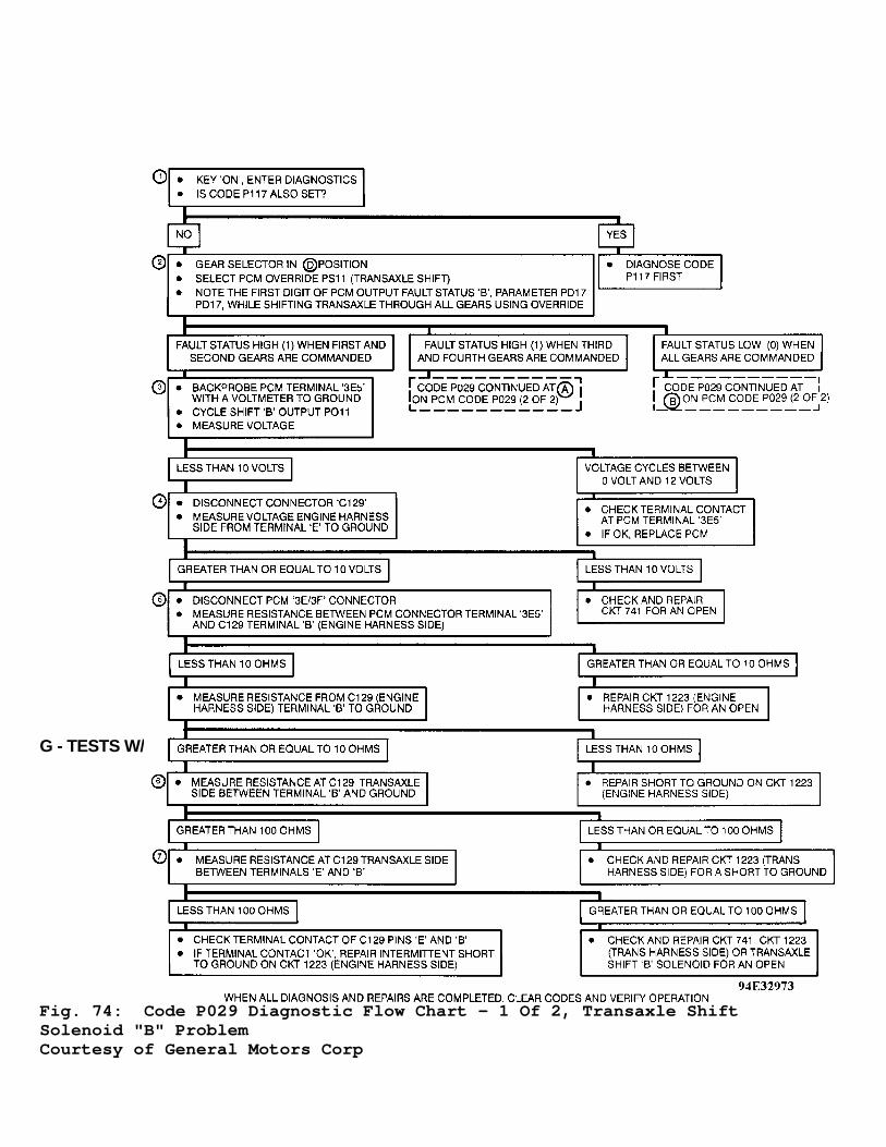
G - TESTS W/CODES - 4.6LArticle Text (p. 103)1995 Cadillac ConcoursFor Ace Mechanics 123 Main Street San Diego Ca 92126
Fig. 74: Code P029 Diagnostic Flow Chart - 1 Of 2, Transaxle ShiftSolenoid "B" ProblemCourtesy of General Motors Corp

G - TESTS W/CODES - 4.6LArticle Text (p. 104)1995 Cadillac ConcoursFor Ace Mechanics 123 Main Street San Diego Ca 92126
Fig. 75: Code P029 Diagnostic Flow Chart - 2 Of 2, Transaxle ShiftSolenoid "B" ProblemCourtesy of General Motors Corp
CODE P030, ISC RPM OUT OF RANGE
PCM controls engine idle RPM by increasing or decreasing

G - TESTS W/CODES - 4.6L
throttle opening using Idle Speed Control (ISC) motor. ISC controlsidle speed any time throttle switch is closed. Code P030 detectsengine RPM out of limits.
Test Conditions Codes P021, P022, P024, P026 and P027 not set, throttleswitch closed, vehicle speed equals zero, battery voltage greater thanor equal to 11 volts, desired engine speed 288 RPM greater than actualRPM, and idle speed control start-up delay over. Engine not receivingpower steering load. PCM not commanding an idle speed anticipate.
Failure Conditions ISC motor in forward mode. TP sensor at least 9.1 degrees orless and ISC extending for 64 seconds or ISC motor in reverse mode, TPsensor position at 1.3 degrees or greater and ISC retracting for 64seconds.
Action PCM turns on MIL.
NOTE: Test numbers refer to numbers on diagnostic chart.
1) This step checks for ISC motor codes that can cause otherproblems. 2) This step checks if cruise control is engaged, causingidle problems. 3) Checks for proper ISC motor operation. 4) Many engine fuel and emissions system faults may causeunstable idle. If base engine idle is not steady, ISC may not be ableto control idle to within 152 RPM of desired idle. For symptomdiagnosis, see H - TESTS W/O CODES article in the ENGINE PERFORMANCEsection. 5) This step checks PCM's ability to control ISC motor bychecking for signal present at ISC motor. 6) This step checks for open or short to ground in circuitNo. 425 or 426. 7) Checks PCM's ability to control ISC motor by checking forsignal present at ISC motor. 8) Checks if ISC motor is receiving signal but not respondingcorrectly. Voltage should fluctuate continuously from negative topositive value.
Note On Intermittents This code may set due to an intermittently sticking ISCmotor.

G - TESTS W/CODES - 4.6LArticle Text (p. 106)1995 Cadillac ConcoursFor Ace Mechanics 123 Main Street San Diego Ca 92126
Fig. 76: Code P030 Schematic, ISC RPM Out Of RangeCourtesy of General Motors Corp

G - TESTS W/CODES - 4.6LArticle Text (p. 107)1995 Cadillac ConcoursFor Ace Mechanics 123 Main Street San Diego Ca 92126
Fig. 77: Code P030 Diagnostic Flow Chart - 1 Of 2, ISC RPM Out OfRangeCourtesy of General Motors Corp

G - TESTS W/CODES - 4.6LArticle Text (p. 108)1995 Cadillac ConcoursFor Ace Mechanics 123 Main Street San Diego Ca 92126
Fig. 78: Code P030 Diagnostic Flow Chart - 2 Of 2, ISC RPM Out OfRangeCourtesy of General Motors Corp
CODE P031, SHORTED MAP SENSOR CIRCUIT
MAP sensor output signal voltage is a DC voltage varying withmanifold pressure. PCM provides a 5-volt reference signal and ground.

G - TESTS W/CODES - 4.6L
MAP signal varies between zero and 5 volts as manifold pressurechanges. As MAP decreases, voltage decreases (low engine load, highvacuum). As MAP increases, voltage increases (high engine load, lowvacuum). PCM uses MAP sensor values to indicate engine load. A highMAP reading indicates heavy load and low MAP indicates low load. CodeP031 is designed to set when PCM detects a MAP sensor signal out ofhigh limits.
Test Conditions Tested continuously. Codes P021 and P022 not set. Enginerunning with throttle angle at 20.5 degrees or less.
Failure Conditions MAP value high for at least .25 second.
Action PCM turns on MIL, disables long term fuel trim and uses asubstitute MAP sensor value based on engine RPM and throttle switchstatus (open or closed). PCM disables torque management and transaxleshift adapts are maintained at current levels.
NOTE: Test numbers refer to numbers on diagnostic chart.
1) If Code P038 is set, check circuit No. 452 for open orshort to voltage. MAP and IAT sensors share this same circuit. 2) PD02 will read 103-105 kPa if MAP sensor or circuit isshorted. 3) If PCM data PD02 goes to 10-16 kPa with connectorunplugged, check for faulty sensor or circuit. 4) Checks circuit No. 432 for short to battery. If circuit isokay, replace PCM.
Note On Intermittents Code P031 could be set during anengine backfire, which cause a rapid increase in MAP value. Check CodeP031 snapshot.

G - TESTS W/CODES - 4.6LArticle Text (p. 110)1995 Cadillac ConcoursFor Ace Mechanics 123 Main Street San Diego Ca 92126
Fig. 79: Code P031 Schematic, Shorted MAP Sensor CircuitCourtesy of General Motors Corp

G - TESTS W/CODES - 4.6LArticle Text (p. 111)1995 Cadillac ConcoursFor Ace Mechanics 123 Main Street San Diego Ca 92126
Fig. 80: Code P031 Diagnostic Flow Chart, Shorted MAP Sensor CircuitCourtesy of General Motors Corp
CODE P032, OPEN MAP SENSOR CIRCUIT
MAP sensor changes resistance based upon manifold vacuum. PCMprovides a 5-volt reference and ground. MAP signal varies between zeroand 5 volts as manifold vacuum varies. Code P032 sets when PCM detectsMAP sensor signal is too low.
Test Conditions (1) Engine speed less than or equal to 700 RPM, throttle angleless than or equal to 18 degrees and TP sensor closed.
Test Conditions (2) Engine speed less than or equal to 1800 RPM, throttle angle

G - TESTS W/CODES - 4.6L
less than or equal to 13 degrees, TP sensor open and transmission notin Park or Neutral.
Failure Conditions MAP value less than 16 kPa for .2 second.
Action PCM turns on MIL. PCM disables long term fuel trim and uses asubstitute MAP value based on engine RPM and throttle switch status(open or closed). PCM disables EVAP control solenoid. PCM disablestorque management and transaxle shift adapts are maintained at currentlevels.
NOTE: Test numbers refer to numbers on diagnostic chart.
1) PD02 will read 10-16 kPa if MAP sensor or related circuitis open. 2) Checks for 5-volt reference signal at sensor connector. Areading of 103-105 kPa means that wiring and PCM are okay. 3) Checks circuit No. 432 for short to ground and circuitsNo. 432 and 474 and MAP sensor circuit for open. 4) Checks circuit No. 432 for short to ground. 5) Checks if 5-volt signal is reaching PCM. If signal ispresent, replace PCM.
Fig. 81: Code P032 Schematic, Open MAP Sensor CircuitCourtesy of General Motors Corp

G - TESTS W/CODES - 4.6LArticle Text (p. 113)1995 Cadillac ConcoursFor Ace Mechanics 123 Main Street San Diego Ca 92126
Fig. 82: Code P032 Diagnostic Flow Chart, Open MAP Sensor CircuitCourtesy of General Motors Corp
CODE P033, EXTENDED TRAVEL BRAKE SWITCH INPUT CIRCUIT PROBLEM
This test assumes that a sudden decrease in non-drive (rear)wheel speed is caused by a brake application. Non-drive wheels andstoplight switch status are supplied to PCM through the serial datafrom the EBTCM.
Test Conditions Codes P090, P106 and P137 not set. Traction control and ABS

G - TESTS W/CODES - 4.6L
systems operating normally and non-drive wheel speed of 36 MPH orgreater.
Failure Conditions A 2 MPH or greater decrease in non-drive wheel speed in 0.2seconds. Transition in the TCC contacts of the TCC brake switch orstop/BTSI/cruise brake switch. No transition noticed in the extendedtravel contact of TCC brake switch. If these conditions are met andcounter reaches 5, Code P033 sets.
Action PCM disables cruise control and substitutes status of TCCcontacts of TCC brake switch input for the extended travel input. PCMturns on SERVICE VEHICLE SOON light message.
NOTE: Test numbers refer to numbers on diagnostic chart.
1) PCM input PI86 should cycle from high to low when brakepedal is depressed and then released. If PI86 remains low, check foropen or short to ground in system. If PI86 remains high, check forshort to voltage in system. 2) If 10 volts or greater is measured, check circuit No. 847or TCC brake switch for open circuit. If less than 10 volts ismeasured, check circuits No. 341 and 847 for a short to ground.
Fig. 83: Code P033 Schematic, Extended Travel Brake Switch InputCircuit ProblemCourtesy of General Motors Corp.

G - TESTS W/CODES - 4.6LArticle Text (p. 115)1995 Cadillac Concours
Fig. 84: Code P033Diagnostic Flow Chart, Extended Travel Brake SwitchInput Circuit ProblemCourtesy of General Motors Corp.
CODE P034, MAP SENSOR SIGNAL TOO HIGH
This test monitors MAP sensor signals for loss of enginevacuum under closed throttle condition. If difference between MAPsignal and calculated BARO is 11 kPa or less for 15 seconds, Code P034sets.
G - TESTS W/CODES - 4.6LArticle Text (p. 116)1995 Cadillac ConcoursFor Ace Mechanics 123 Main Street San Diego Ca 92126
Test Conditions Codes P021, P022, P026, P027, P031 and P032 not set,throttle switch closed, engine speed greater than or equal to 400 RPM,throttle angle less than or equal to 18 degrees and BARO at least 75kPa.
Failure Conditions Difference between MAP and calculated BARO sensor value 11kPa or less for 15 seconds.
Action PCM turns on MIL. PCM uses a substitute MAP sensor valuebased on engine RPM and throttle position switch status. PCM disableslong term fuel trim. PCM disables EVAP canister solenoid. PCM disablestorque management and transaxle shift adapts are maintained at currentlevels.
NOTE: Test numbers refer to numbers on diagnostic chart.
1) MAP at idle should be 30-50 kPa, depending on engine load.BARO pressure should be 85-105 kPa, depending upon altitude. 2) Check for vacuum at fuel pressure regulator hose. At idle,typical vacuum reading should be 14-20 in. Hg, depending on engineload. 3) PCM data PD02 should read 10-16 kPa MAP sensor connectordisconnected. If PD02 reads greater than 16 kPa, check circuit No. 432for short to voltage. 4) Checks for short to voltage inside intake manifold. 5) Checks for short to voltage on circuit No. 452 or 474.Also checks for high resistance on circuit No. 452. Ensure transaxletemperature sensor connector is disconnected to eliminate voltage.
CODE P035, IGNITION GROUND VOLTAGE OUT OF RANGE
This test monitors the REF LO voltage (circuit No. 453) inputto PCM and sets Code P035 if voltage difference between REF LO and PCMpower ground is greater than preset values. PCM internally adds 2.5volts to REF LO signal. If voltage is greater than 3.98 volts or lessthan 1.04 volts, PCM will set Code P035.
Test Conditions Code P016 not set.
Failure Conditions Voltage difference between PCM ground and ignition controlmodule REF LO is 1.48 volts or greater for one second or REF LOvoltage is -1.46 volts or less for one second.
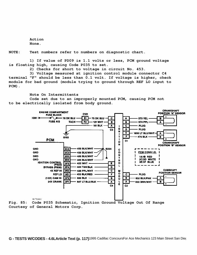
G - TESTS W/CODES - 4.6LArticle Text (p. 117)1995 Cadillac ConcoursFor Ace Mechanics 123 Main Street San Diego Ca 92126
Action None.
NOTE: Test numbers refer to numbers on diagnostic chart.
1) If value of PD09 is 1.1 volts or less, PCM ground voltageis floating high, causing Code P035 to set. 2) Checks for short to voltage in circuit No. 453. 3) Voltage measured at ignition control module connector C4terminal "F" should be less than 0.1 volt. If voltage is higher, checkmodule for bad ground (module trying to ground through REF LO input toPCM).
Note On Intermittents Code set due to an improperly mounted PCM, causing PCM notto be electrically isolated from body ground.
Fig. 85: Code P035 Schematic, Ignition Ground Voltage Out Of RangeCourtesy of General Motors Corp.
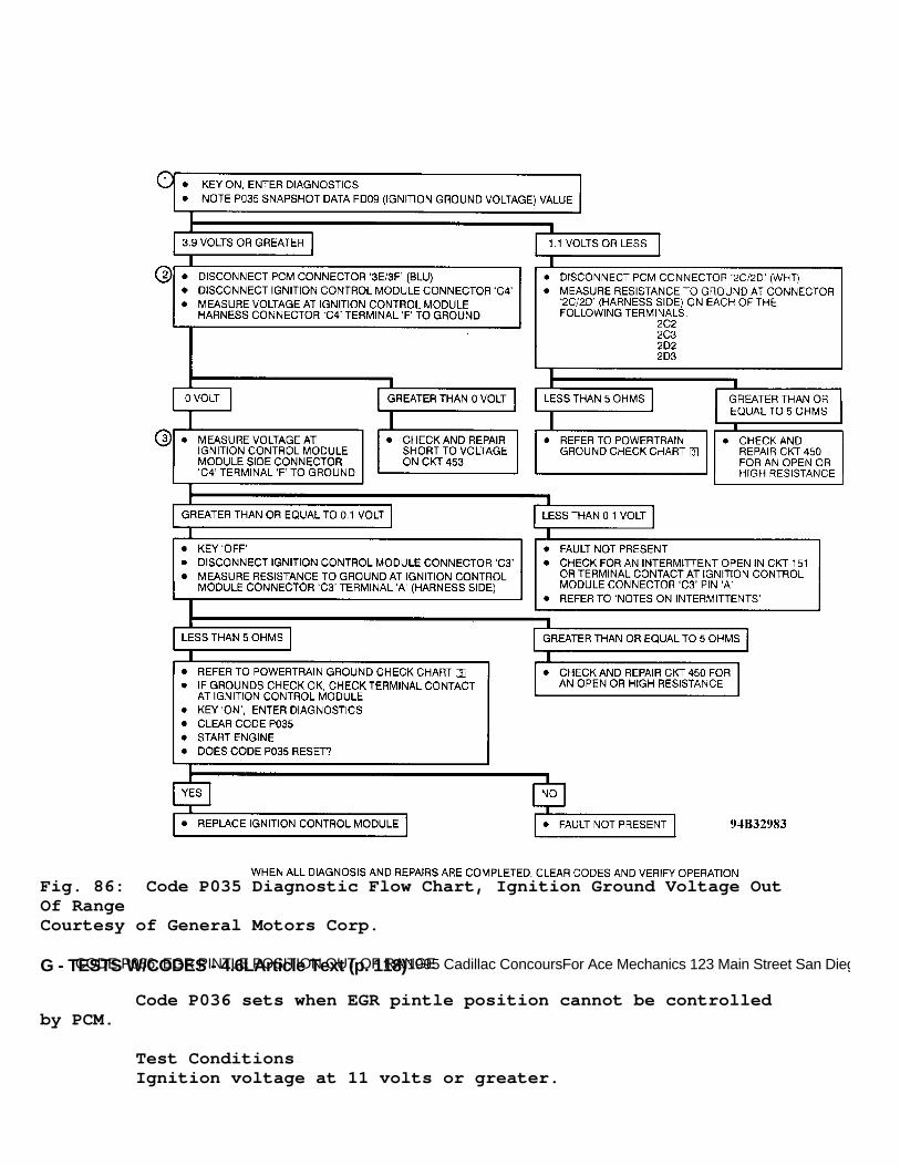
G - TESTS W/CODES - 4.6LArticle Text (p. 118)1995 Cadillac ConcoursFor Ace Mechanics 123 Main Street San Diego Ca 92126
Fig. 86: Code P035 Diagnostic Flow Chart, Ignition Ground Voltage OutOf RangeCourtesy of General Motors Corp.
CODE P036, EGR PINTLE POSITION OUT OF RANGE
Code P036 sets when EGR pintle position cannot be controlledby PCM.
Test Conditions Ignition voltage at 11 volts or greater.

G - TESTS W/CODES - 4.6LArticle Text (p. 119)1995 Cadillac ConcoursFor Ace Mechanics 123 Main Street San Diego Ca 92126
Failure Conditions Difference between commanded and actual EGR position isgreater than 25 counts for 10 seconds or learned EGR closed positionis less than 9 counts or greater than 103 counts.
Action PCM turns on MIL. PCM disables EGR solenoid for entireignition cycle. Transaxle shift adapts are maintained at currentlevels.
NOTE: Test numbers refer to numbers on diagnostic chart.
1) Checks if EGR pintle position feedback is within a validrange with EGR off. 2) This step forces a high signal on the feedback circuit andchecks for an appropriate result. 3) This step removes signal from feedback circuit and checksfor an appropriate result. 4) Jumper voltage should read 5 volts since 5-volt referenceline is jumpered to feedback line. 5) With EGR off (EGR overridden to zero), EGR pintle positionshould read less than 50 counts. 6) With EGR valve commanded to 50 percent, EGR pintleposition should read 100-150 counts. 7) With EGR valve on full, EGR pintle position should begreater than 200 counts. 8) Code P036 snapshot parameter PD07 (EGR pintle position)can help determine the root cause even if problem cannot bereproduced. A low pintle position (less than 9 counts) recorded in thesnapshot means a low feedback voltage caused the code to set. A highpintle position (greater than 250 counts) recorded in the snapshotmeans a high feedback voltage caused the code to set. An intermittentpintle position (9-250 counts) recorded in the snapshot means thatcode was set because PCM could not control the EGR solenoid either dueto intermittents in the solenoid (circuits No. 435 and 741) or EGRvalve is sticking.
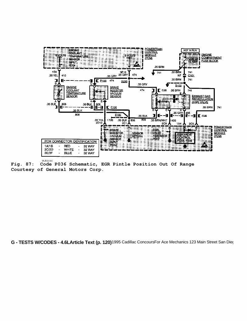
G - TESTS W/CODES - 4.6LArticle Text (p. 120)1995 Cadillac ConcoursFor Ace Mechanics 123 Main Street San Diego Ca 92126
Fig. 87: Code P036 Schematic, EGR Pintle Position Out Of RangeCourtesy of General Motors Corp.

G - TESTS W/CODES - 4.6LArticle Text (p. 121)1995 Cadillac ConcoursFor Ace Mechanics 123 Main Street San Diego Ca 92126
Fig. 88: Code P036 Diagnostic Flow Chart - 1 Of 2, EGR PintlePosition Out Of RangeCourtesy of General Motors Corp.
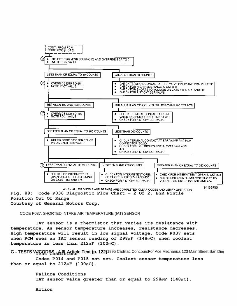
G - TESTS W/CODES - 4.6LArticle Text (p. 122)1995 Cadillac ConcoursFor Ace Mechanics 123 Main Street San Diego Ca 92126
Fig. 89: Code P036 Diagnostic Flow Chart - 2 Of 2, EGR PintlePosition Out Of RangeCourtesy of General Motors Corp.
CODE P037, SHORTED INTAKE AIR TEMPERATURE (IAT) SENSOR
IAT sensor is a thermistor that varies its resistance withtemperature. As sensor temperature increases, resistance decreases.High temperature will result in low signal voltage. Code P037 setswhen PCM sees an IAT sensor reading of 298øF (148øC) when coolanttemperature is less than 212øF (100øC).
Test Conditions Codes P014 and P015 not set. Coolant sensor temperature lessthan or equal to 212øF (100øC).
Failure Conditions IAT sensor value greater than or equal to 298øF (148øC).
Action
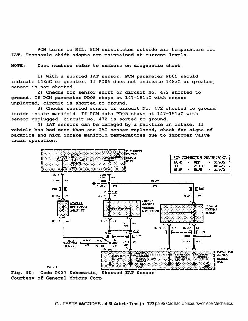
G - TESTS W/CODES - 4.6LArticle Text (p. 123)1995 Cadillac ConcoursFor Ace Mechanics 123 Main Street San Diego Ca 92126
PCM turns on MIL. PCM substitutes outside air temperature forIAT. Transaxle shift adapts are maintained at current levels.
NOTE: Test numbers refer to numbers on diagnostic chart.
1) With a shorted IAT sensor, PCM parameter PD05 shouldindicate 148øC or greater. If PD05 does not indicate 148øC or greater,sensor is not shorted. 2) Checks for sensor short or circuit No. 472 shorted toground. If PCM parameter PDO5 stays at 147-151øC with sensorunplugged, circuit is shorted to ground. 3) Checks shorted sensor or circuit No. 472 shorted to groundinside intake manifold. If PCM data PD05 stays at 147-151øC withsensor unplugged, circuit No. 472 is sorted to ground. 4) IAT sensors can be damaged by a backfire in intake. Ifvehicle has had more than one IAT sensor replaced, check for signs ofbackfire and high intake manifold temperatures due to improper valvetrain operation.
Fig. 90: Code P037 Schematic, Shorted IAT SensorCourtesy of General Motors Corp.

G - TESTS W/CODES - 4.6LArticle Text (p. 124)1995 Cadillac ConcoursFor Ace Mechanics 123 Main Street San Diego Ca 92126
Fig. 91: Code P037 Diagnostic Flow Chart, Shorted IAT SensorCourtesy of General Motors Corp.
CODE P038, OPEN INTAKE AIR TEMPERATURE (IAT) SENSOR
IAT sensor is a thermistor that varies its resistance basedon temperature. As temperature of sensor decreases, sensor resistanceincreases. Code P038 sets when PCM sees low voltage signal whencoolant sensor temperature is 14øF (-10øC) or greater.
Test Conditions Code P047 not set. Outside air temperature sensor has notfailed. Outside air temperature 14øF (-10øC) or greater or differencebetween outside air temperature and IAT is greater than 63øF (17øC).Vehicle speed at 7 MPH or greater for at least 5 seconds. Engine speedat 500 RPM or greater for more than 20 seconds.
Failure Conditions IAT sensor value less than 35øF (-37øC).
Action PCM turns on MIL. PCM substitutes outside air temperature forIAT. Transaxle shift adapts are maintained at current levels.

G - TESTS W/CODES - 4.6LArticle Text (p. 125)1995 Cadillac ConcoursFor Ace Mechanics 123 Main Street San Diego Ca 92126
NOTE: Test numbers refer to numbers on diagnostic chart.
1) If IAT sensor is open, PCM parameter PD05 should indicate-37øC or less. If PD05 does not indicate -37ø or less, sensor signalis not open. 2) Checks PCM and circuit No. 472 from PCM to sensorconnector. If PCM data PD05 indicates 147-151øC with connectorterminal "A" shorted to ground, sensor circuits and PCM are okay. 3) Checks for open sensor circuit No. 452 (ground). If PCMdata PD05 reads 147-151øC with sensor connector terminals "A" and "B"jumpered, then circuit No. 452 and PCM are okay. 4) Checks if circuit No. 472 or if PCM is open. 5) Checks if circuits No. 452 or 472 or IAT sensor is open orshorted to voltage. 6) IAT sensor can be damaged by backfire in intake manifold.If vehicle has had multiple IAT sensor replacements, check for signsof backfire.
Fig. 92: Code P038 Schematic, Open Intake Air Temperature (IAT)SensorCourtesy of General Motors Corp.

G - TESTS W/CODES - 4.6LArticle Text (p. 126)1995 Cadillac ConcoursFor Ace Mechanics 123 Main Street San Diego Ca 92126
Fig. 93: Code P038 Diagnostic Flow Chart, Open IAT SensorCourtesy of General Motors Corp.
CODE P039, TCC ENGAGEMENT PROBLEM
This code test monitors engine RPM and vehicle speed andcompares them. PCM will set code when engine speed exceeds fault valuefor a particular vehicle speed. This code can set due to an electricalproblem or slippage of TCC or transaxle clutches. If a TCC failure has

G - TESTS W/CODES - 4.6L
occurred, failure is more likely to be observed under high road load(high MAP) conditions. Use code snapshot data to confirm failure.
Test Conditions Codes P024, P026, P027, P028, P031, P032, P034, P056 andP075 not set, transaxle in 3rd or 4th gear and engine running. TCCcommanded on (100 percent). Transaxle not in Park or Neutral. Throttleposition switch open. Delivered torque from engine not 32 ft. lbs. orless (coast down condition). Delivered torque from engine not 508 ft.lbs. or greater (engine under extreme load).
Failure Conditions: 3.11 Ratio (VIN Y) - Slip speed greater than acceptable valuebased on engine torque delivered for 4.5 seconds. See chart. 3.71 Ratio (VIN 9) - Slip speed at 48 RPM or greater for 4.5seconds.
Action PCM turns on MIL. TCC disabled for the entire ignition cycle.
NOTE: Test number refers to number on diagnostic chart.
1) Testing TCC brake switch input to PCM PI71. If testpasses, display will change from HI 0 to HI X. If test fails, displaywill not change. 2) Checks for open in circuit No. 420 between TCC solenoidand TCC brake switch connectors. 3) Checks for open or short inside transaxle. Resistanceshould be 10-40 ohms. 4) Checks if circuit No. 422 is open or if PCM in unable tocontrol output. 5) Checks PCM's ability to control TCC output. 6) Checks if TCC is operating correctly by checking amount ofTCC slip when clutch is engaged.
Note On Intermittent Intermittent Code P039 nay be caused by delayed TCCengagement (usually first apply after a cold start) or by TCC slippageduring high engine load conditions. Delayed TCC engaged can be checkedusing PCM output override PS01 (TCC solenoid) to engage and disengageand time how long it takes TCC to engage by watching PCM data PD73.Delays of greater than 5 seconds may cause code to set. TCC slippage during high load conditions can be determined bylooking at Code P039 snapshot data. High throttle angle (PD01), MAP(PD02) may indicate a high load condition. Duplicating high loadconditions may cause the code to set.

G - TESTS W/CODES - 4.6LArticle Text (p. 128)1995 Cadillac ConcoursFor Ace Mechanics 123 Main Street San Diego Ca 92126
Fig. 94: Code P039 Schematic - 1 Of 2, TCC Engagement ProblemCourtesy of General Motors Corp.
Fig. 95: Code P039 Schematic - 2 Of 2, TCC Engagement ProblemCourtesy of General Motors Corp.

G - TESTS W/CODES - 4.6LArticle Text (p. 129)1995 Cadillac ConcoursFor Ace Mechanics 123 Main Street San Diego Ca 92126
Fig. 96: Code P039 Diagnostic Flow Chart - 1 Of 2, TCC EngagementProblemCourtesy of General Motors Corp.

G - TESTS W/CODES - 4.6LArticle Text (p. 130)1995 Cadillac ConcoursFor Ace Mechanics 123 Main Street San Diego Ca 92126Fig. 97: Code P039 Diagnostic Flow Chart - 2 Of 2, TCC EngagementProblemCourtesy of General Motors Corp.
CODE P040, OPEN PSPS CIRCUIT
This code test monitors Power Steering Pressure Switch(PSPS). When a load is placed on power steering, such as full lock,switch opens. Code P040 sets when vehicle speed is greater than 45 MPH

G - TESTS W/CODES - 4.6L
and pressure switch is open.
Test Conditions Engine running. Vehicle speed greater than or equal to 45MPH.
Failure Conditions Power steering switch open for 60 seconds.
Action PCM turns on MIL.
NOTE: Test numbers refer to numbers on diagnostic chart.
1) Checks if PI85 will cycle from high to low to high. IfPI85 stays low, check for open or short to ground in circuit. If PI85stays high, check for short to voltage in circuit. 2) Checks is circuit No. 495 is shorted to voltage or ifpower steering is faulty. 3) Checks if circuit No. 741 or fuse D1 is open. 4) Checks if power steering pressure switch is open. 5) Checks if circuit No. 495 is open or if PCM is faulty.
Fig. 98: Code P040 Schematic, Open PSPS CircuitCourtesy of General Motors Corp.

G - TESTS W/CODES - 4.6LArticle Text (p. 132)1995 Cadillac ConcoursFor Ace Mechanics 123 Main Street San Diego Ca 92126
Fig. 99: Code P040 Diagnostic Flow Chart, Open PSPS CircuitCourtesy of General Motors Corp.
CODE P041, NO CAM REFERENCE SENS SGNL FROM IGN CONTROL MODULE
Checks for CAM reference pulses not received when 4X
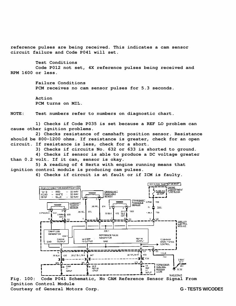
G - TESTS W/CODES - 4.6L
reference pulses are being received. This indicates a cam sensorcircuit failure and Code P041 will set.
Test Conditions Code P012 not set, 4X reference pulses being received andRPM 1600 or less.
Failure Conditions PCM receives no cam sensor pulses for 5.3 seconds.
Action PCM turns on MIL.
NOTE: Test numbers refer to numbers on diagnostic chart.
1) Checks if Code P035 is set because a REF LO problem cancause other ignition problems. 2) Checks resistance of camshaft position sensor. Resistanceshould be 800-1200 ohms. If resistance is greater, check for an opencircuit. If resistance is less, check for a short. 3) Checks if circuits No. 632 or 633 is shorted to ground. 4) Checks if sensor is able to produce a DC voltage greaterthan 0.2 volt. If it can, sensor is okay. 5) A reading of 4 Hertz with engine running means thatignition control module is producing cam pulses. 6) Checks if circuit is at fault or if ICM is faulty.
Fig. 100: Code P041 Schematic, No CAM Reference Sensor Signal FromIgnition Control ModuleCourtesy of General Motors Corp.

G - TESTS W/CODES - 4.6LArticle Text (p. 134)1995 Cadillac Concours
Fig. 101: Code P041 Diagnostic Flow Chart, No CAM Reference SensorSignal From Ignition Control ModuleCourtesy of General Motors Corp.
CODE P042, FRONT OXYGEN SENSOR LEAN SIGNAL

G - TESTS W/CODES - 4.6LArticle Text (p. 135)1995 Cadillac ConcoursFor Ace Mechanics 123 Main Street San Diego Ca 92126
PCM provides a .45-volt reference signal to oxygen sensor oncircuit No. 412. When oxygen sensor temperature is less than 392øF(200øC), sensor signal voltage will be about .45 volt and PCM willkeep system in open loop operation. When oxygen sensor temperature isgreater than 392øF (200øC), sensor will begin to generate a signalvoltage. In a rich environment, signal voltage will be greater than .45 volt. In a lean environment, signal voltage will be less than .45volt. If PCM is in good control of air/fuel mixture, mixture willchange from rich to lean rapidly (at least one change every 2seconds). When PCM sees oxygen sensor is generating a signal voltage(greater than .45 volt), PCM will send system into closed loopoperation. In closed loop operation, PCM will adjust fuel deliveryrate to engine based on oxygen sensor readings.Code P042 sets if oxygen sensor stays at lean voltage more than 50seconds during test conditions. Code P042 also sets when an oxygensensor circuit fault giving a false lean indication exists or whenair/fuel ratio is actually lean due to a vacuum leak or fuel controlsystem fault.
Test Conditions Codes P014, P015, P016, P021, P022, P026, P027, P031, P032and P034 not set. Throttle switch open, throttle angle 5-25 degrees,coolant temperature 180-268øF (82-131øC), oxygen sensor ready (closedloop), RPM at least 800 and MAP at least 32 kPa. Canister purgeoccurred at full duty cycle for 2 minutes since engine was running andthrottle angle 10 degrees or greater. Long term fuel trim not ineffect.
Failure Conditions Oxygen sensor status stays lean more than 50 seconds.
Action PCM turns on MIL. PCM turns on canister purge solenoid ifCode P044 is also set. Transaxle shift adapts are maintained atcurrent levels.
NOTE: Test numbers refer to numbers on diagnostic chart.
1) If Code P017 is present, diagnose this code first since anoxygen sensor not ready can cause other emission related problems. 2) If oxygen sensor is operating correctly, voltage shouldfluctuate at greater than 0.3 volt. A lean sensor condition will causevoltage to remain at less than 0.3 volt. 3) If voltage measured is greater than 0.15 volt, PCM andcircuit No. 412 are okay.
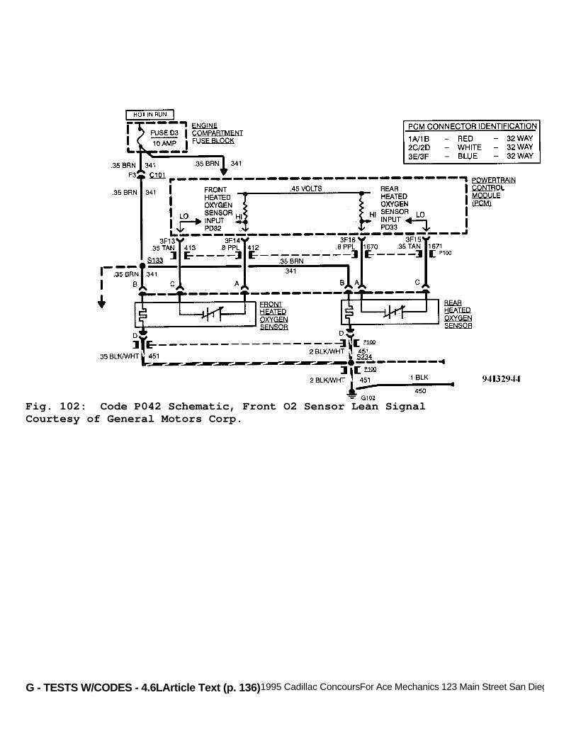
G - TESTS W/CODES - 4.6LArticle Text (p. 136)1995 Cadillac ConcoursFor Ace Mechanics 123 Main Street San Diego Ca 92126
Fig. 102: Code P042 Schematic, Front O2 Sensor Lean SignalCourtesy of General Motors Corp.
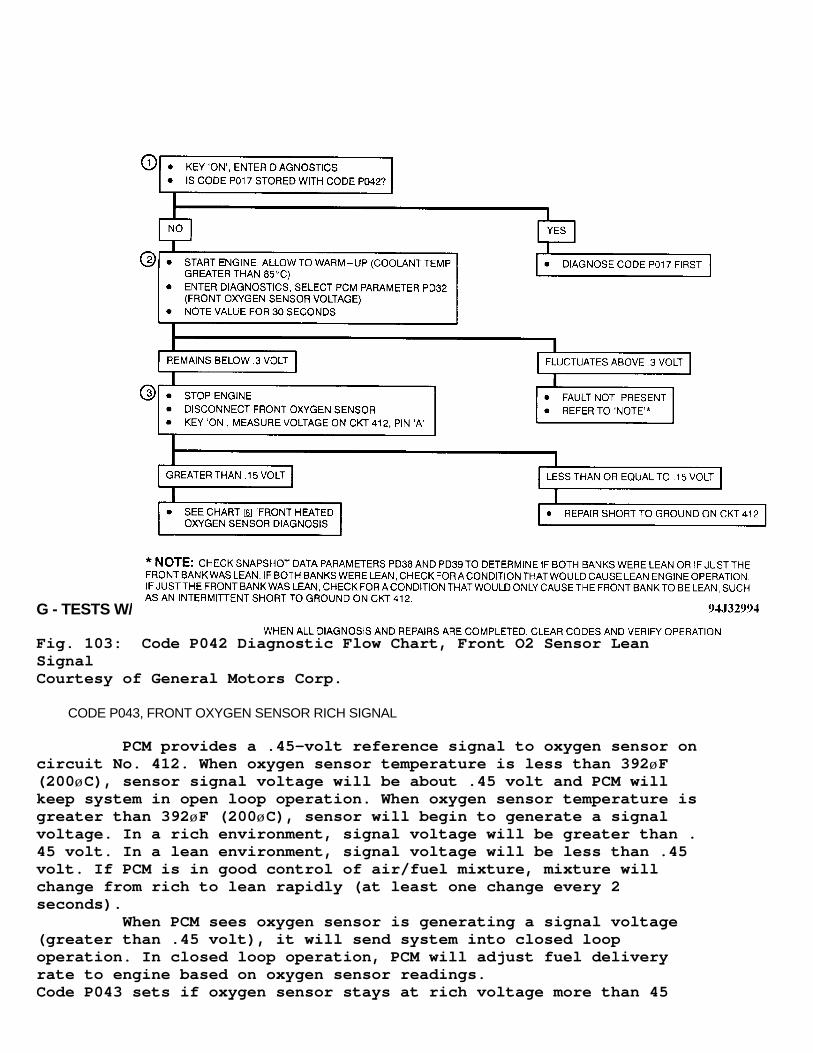
G - TESTS W/CODES - 4.6LArticle Text (p. 137)1995 Cadillac ConcoursFor Ace Mechanics 123 Main Street San Diego Ca 92126
Fig. 103: Code P042 Diagnostic Flow Chart, Front O2 Sensor LeanSignalCourtesy of General Motors Corp.
CODE P043, FRONT OXYGEN SENSOR RICH SIGNAL
PCM provides a .45-volt reference signal to oxygen sensor oncircuit No. 412. When oxygen sensor temperature is less than 392øF(200øC), sensor signal voltage will be about .45 volt and PCM willkeep system in open loop operation. When oxygen sensor temperature isgreater than 392øF (200øC), sensor will begin to generate a signalvoltage. In a rich environment, signal voltage will be greater than .45 volt. In a lean environment, signal voltage will be less than .45volt. If PCM is in good control of air/fuel mixture, mixture willchange from rich to lean rapidly (at least one change every 2seconds). When PCM sees oxygen sensor is generating a signal voltage(greater than .45 volt), it will send system into closed loopoperation. In closed loop operation, PCM will adjust fuel deliveryrate to engine based on oxygen sensor readings.Code P043 sets if oxygen sensor stays at rich voltage more than 45
G - TESTS W/CODES - 4.6L
seconds during test conditions. Code P043 also sets when oxygen sensorcircuit fails or when air/fuel ratio is actually rich due to fuelcontrol or emissions system fault.
Test Conditions Codes P014, P015, P016, P021, P022, P026, P027, P031, P032and P034 not set, throttle switch open, throttle angle 5-30 degrees,coolant sensor temperature 180-268øF (82-131øC), sensor ready (closedloop), vehicle not accelerating or decelerating, and engine speedgreater than or equal to 800 RPM. Canister purge occurred at full dutycycle for 2 minutes since engine was running and throttle angle at 10degrees or greater. Long term fuel trim not in effect.
Failure Conditions Oxygen sensor stays rich for more than 50 seconds.
Action PCM turns on MIL. PCM turns on canister purge solenoid ifCode P045 is also set. Transaxle shift adapts are maintained atcurrent levels.
NOTE: Test numbers refer to numbers on diagnostic chart.
1) If Code P017 is present, diagnose this code first since anoxygen sensor not ready can cause other emission related problems. 2) If oxygen sensor is operating correctly, voltage shouldfluctuate at less than 0.6 volt. A rich sensor condition will causevoltage to remain at greater than 0.6 volt. 3) If voltage measured is less than one volt, PCM and circuitNo. 412 are okay.

G - TESTS W/CODES - 4.6LArticle Text (p. 139)1995 Cadillac ConcoursFor Ace Mechanics 123 Main Street San Diego Ca 92126
Fig. 104: Code P043 Schematic, Front O2 Sensor Rich SignalCourtesy of General Motors Corp.
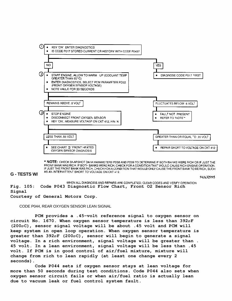
G - TESTS W/CODES - 4.6LArticle Text (p. 140)1995 Cadillac ConcoursFor Ace Mechanics 123 Main Street San Diego Ca 92126
Fig. 105: Code P043 Diagnostic Flow Chart, Front O2 Sensor RichSignalCourtesy of General Motors Corp.
CODE P044, REAR OXYGEN SENSOR LEAN SIGNAL
PCM provides a .45-volt reference signal to oxygen sensor oncircuit No. 1670. When oxygen sensor temperature is less than 392øF(200øC), sensor signal voltage will be about .45 volt and PCM willkeep system in open loop operation. When oxygen sensor temperature isgreater than 392øF (200øC), sensor will begin to generate a signalvoltage. In a rich environment, signal voltage will be greater than .45 volt. In a lean environment, signal voltage will be less than .45volt. If PCM is in good control of air/fuel mixture, mixture willchange from rich to lean rapidly (at least one change every 2seconds). Code P044 sets if oxygen sensor stays at lean voltage formore than 50 seconds during test conditions. Code P044 also sets whenoxygen sensor circuit fails or when air/fuel ratio is actually leandue to vacuum leak or fuel control system fault.

G - TESTS W/CODES - 4.6LArticle Text (p. 141)
Test Conditions Codes P014, P015, P016, P021, P022, P026, P027, P031, P032and P034 not set. Throttle switch open, throttle angle 5-25 degrees,coolant sensor temperature 180-268øF (82-131øC), sensor ready (closedloop), RPM greater than or equal to 800 and MAP at 32 kPa or greater.Canister purge occurred at full duty cycle for 2 minutes since enginewas running and throttle angle 10 degrees or greater. Long term fueltrim not in effect.
Failure Conditions Oxygen sensor status stays lean more than 50 seconds.
Action PCM turns on MIL. PCM turns on canister purge solenoid ifCode P042 is also set. Transaxle shift adapts maintained at currentlevels.
NOTE: Test numbers refer to numbers on diagnostic chart.
1) If Code P013 is present, diagnose this code first since anoxygen sensor not ready can cause other emission related problems. 2) If oxygen sensor is operating correctly, voltage shouldfluctuate at greater than 0.3 volt. A lean sensor condition will causevoltage to remain at less than 0.3 volt. 3) If voltage measured is greater than 0.15 volt, PCM andcircuit No. 1670 are okay.
Fig. 106: Code P044 Schematic, Rear O2 Sensor Lean SignalCourtesy of General Motors Corp.

G - TESTS W/CODES - 4.6LArticle Text (p. 142)1995 Cadillac ConcoursFor Ace Mechanics 123 Main Street San Diego Ca 92126
Fig. 107: Code P044 Diagnostic Flow Chart, Rear O2 Sensor Lean SignalCourtesy of General Motors Corp.
CODE P045, REAR OXYGEN SENSOR RICH SIGNAL
PCM provides a .45-volt reference signal to oxygen sensor oncircuit No. 1670. When oxygen sensor temperature is less than 392øF(200øC), sensor signal voltage will be about .45 volt and PCM willkeep system in open loop operation. When oxygen sensor temperature isgreater than 392øF (200øC), sensor will swing from rich to leanrapidly, at least one swing every 2 seconds, if PCM is in good controlof air/fuel mixture. Code P045 sets when sensor stays at a rich voltage for morethan 50 seconds during the test conditions. Code P045 will also setwhen oxygen sensor circuit fails or when air/fuel ratio is actuallyrich due to fuel control or emissions system fault.
Test Conditions Codes P014, P015, P016, P021, P022, P026, P027, P031, P032and P034 not set. Throttle switch open, throttle angle 5-25 degrees,coolant temperature 180-268øF (82-131øC), oxygen sensor ready (closedloop), and engine speed at least 800 RPM. Canister purge occurred atfull duty cycle for 2 minutes since engine was running and throttle
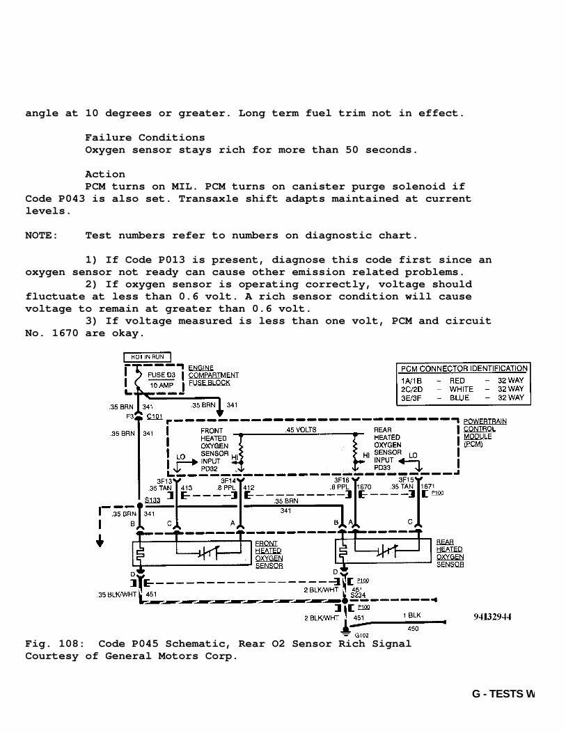
G - TESTS W/CODES - 4.6L
angle at 10 degrees or greater. Long term fuel trim not in effect.
Failure Conditions Oxygen sensor stays rich for more than 50 seconds.
Action PCM turns on MIL. PCM turns on canister purge solenoid ifCode P043 is also set. Transaxle shift adapts maintained at currentlevels.
NOTE: Test numbers refer to numbers on diagnostic chart.
1) If Code P013 is present, diagnose this code first since anoxygen sensor not ready can cause other emission related problems. 2) If oxygen sensor is operating correctly, voltage shouldfluctuate at less than 0.6 volt. A rich sensor condition will causevoltage to remain at greater than 0.6 volt. 3) If voltage measured is less than one volt, PCM and circuitNo. 1670 are okay.
Fig. 108: Code P045 Schematic, Rear O2 Sensor Rich SignalCourtesy of General Motors Corp.

G - TESTS W/CODES - 4.6LArticle Text (p. 144)1995 Cadillac ConcoursFor Ace Mechanics 123 Main Street San Diego Ca 92126
Fig. 109: Code P045 Diagnostic Flow Chart, Rear O2 Sensor Rich SignalCourtesy of General Motors Corp.
CODE P046, FRONT-TO-REAR BANK FUELING IMBALANCE
PCM controls rear bank fueling based upon rear oxygen sensorand front bank fueling based upon front oxygen sensor. Likely causesfor imbalance include lean or faulty injectors on one side of engine,cracked or fouled spark plugs, or exhaust or intake manifold leaks.
Test Conditions Tested continuously.
Failure Conditions Front bank block learn values differ from rear bank blocklearn values by more than 15 counts for 10 minutes.
Action PCM turns on MIL.
NOTE: Test numbers refer to numbers on diagnostic chart.

G - TESTS W/CODES - 4.6LArticle Text (p. 145)1995 Cadillac ConcoursFor Ace Mechanics 123 Main Street San Diego Ca 92126
1) If any other codes are present, diagnose them firstbecause they can cause a fueling imbalance. 2) This test checks for a physical or mechanical problemcausing Code P046 to set. 3) Injector bank that is farthest from neutral value of 128is bank which is out of fuel. Refer to PCM DATA PARAMETER. See Fig. 2.See appropriate chart under POWERTRAIN CHARTS.
Fig. 110: Code P046 Schematic, Front-To-Rear Bank Fueling ImbalanceCourtesy of General Motors Corp.

G - TESTS W/CODES - 4.6LArticle Text (p. 146)1995 Cadillac ConcoursFor Ace Mechanics 123 Main Street San Diego Ca 92126
Fig. 111: Code P046 Diagnostic Flow Chart, Front-To-Rear Bank FuelingImbalanceCourtesy of General Motors Corp.
CODE P047 & P107, IPC-TO-PCM DATA LINK PROBLEM
PCM and IPC share information through Universal AsynchronousReceiver Transmitter (UART). IPC is master link and data are onlytransmitted at IPC request. Data are sent in 8-character blocks at arate of 8192 characters per second. Data from PCM to IPC contain engine operating information.PCM-IPC data include CTS, RPM and injector pulse width values so IPCcan control cooling fans, display RPM and calculate MPG for display atDriver Information Center (DIC) panel. IPC sends PCM A/C status to beused for idle speed control and ambient temperature for use in TCCapplication and release decisions. Codes P047/P107 are set in PCM in event of a UART failure. Iffault is a current failure, PCM will not be able to communicate withIPC and IPC Code IO34 will be displayed as current. Code P047/P107 iscurrent in PCM but cannot be sent (displayed) to IPC because of UARTfault. If UART fault is corrected, Codes P047, P107 and IPC Code IO34will be displayed as history codes. Code P047 & P107 should be diagnosed using chart for IPC Code
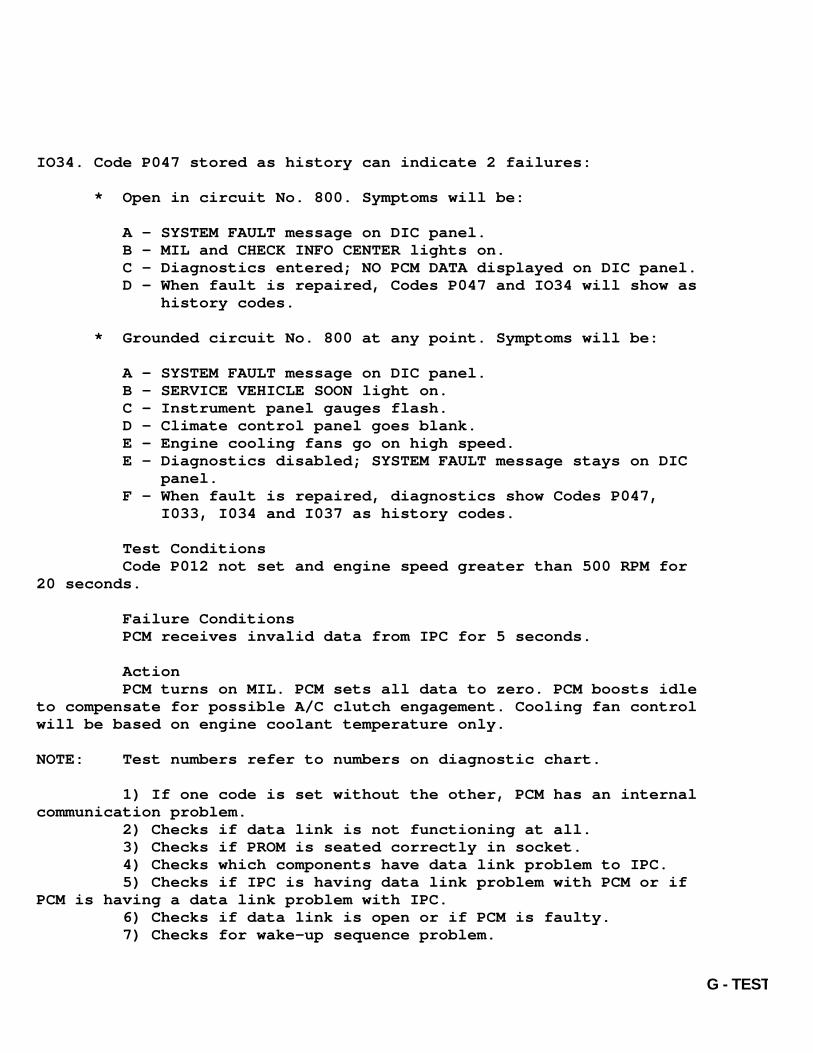
G - TESTS W/CODES - 4.6L
IO34. Code P047 stored as history can indicate 2 failures:
* Open in circuit No. 800. Symptoms will be:
A - SYSTEM FAULT message on DIC panel. B - MIL and CHECK INFO CENTER lights on. C - Diagnostics entered; NO PCM DATA displayed on DIC panel. D - When fault is repaired, Codes P047 and IO34 will show as history codes.
* Grounded circuit No. 800 at any point. Symptoms will be:
A - SYSTEM FAULT message on DIC panel. B - SERVICE VEHICLE SOON light on. C - Instrument panel gauges flash. D - Climate control panel goes blank. E - Engine cooling fans go on high speed. E - Diagnostics disabled; SYSTEM FAULT message stays on DIC panel. F - When fault is repaired, diagnostics show Codes P047, I033, I034 and I037 as history codes.
Test Conditions Code P012 not set and engine speed greater than 500 RPM for20 seconds.
Failure Conditions PCM receives invalid data from IPC for 5 seconds.
Action PCM turns on MIL. PCM sets all data to zero. PCM boosts idleto compensate for possible A/C clutch engagement. Cooling fan controlwill be based on engine coolant temperature only.
NOTE: Test numbers refer to numbers on diagnostic chart.
1) If one code is set without the other, PCM has an internalcommunication problem. 2) Checks if data link is not functioning at all. 3) Checks if PROM is seated correctly in socket. 4) Checks which components have data link problem to IPC. 5) Checks if IPC is having data link problem with PCM or ifPCM is having a data link problem with IPC. 6) Checks if data link is open or if PCM is faulty. 7) Checks for wake-up sequence problem.

G - TESTS W/CODES - 4.6LArticle Text (p. 148)1995 Cadillac ConcoursFor Ace Mechanics 123 Main Street San Diego Ca 92126
Fig. 112: Code P047 & P107 Schematic, IPC-To-PCM Data Link ProblemCourtesy of General Motors Corp.

G - TESTS W/CODES - 4.6LArticle Text (p. 149)1995 Cadillac ConcoursFor Ace Mechanics 123 Main Street San Diego Ca 92126
Fig. 113: Code P047 & P107 Diagnostic Flow Chart, IPC-To-PCM DataLink ProblemCourtesy of General Motors Corp.
CODE P048, EGR SYSTEM FAULT
To perform test, PCM turns off EGR flow to engine and

G - TESTS W/CODES - 4.6L
monitors oxygen sensor (closed loop) integrator. With EGR off,integrator should swing to a greater value, reflecting leaner air/fuelmixtures. If integrator does not swing to a greater value, PCM assumeseither EGR was turned off before test started or EGR is flowing andPCM does not have ability to turn it off. PCM monitors EGR 5 times ina given key cycle. If EGR does not respond 3 or more times during akey cycle, Code P048 is set.
Test Conditions EGR failed in entire ignition cycle. Codes P013, P014, P015,P017, P021, P022, P024, P031, P032, P034, P042, P043, P044, P045 andP075 not set and 9.2 seconds have elapsed since closed loop fuelcontrol was enabled. Coolant temperature 176-230øF (80-110øC), MAPbetween 50-80 kPa. Engine speed between 1250-1850 RPM and vehiclespeed at 35 MPH or greater. Ignition voltage at 11 volts or greater,and 5 seconds prior to test EGR system at full, rear oxygen sensortoggles for 5 times per second and rear short term fuel trim is at 135counts or less.
Failure Conditions PCM turns off EGR system for 5 seconds. PCM monitors rearfuel integrator for change. Oxygen sensor fails to indicate a leanermixture in at least 3 of 5 tests during key cycle.
Action PCM turns on MIL. EGR is disabled for entire key cycle andtransaxle shift adapts are maintained at current levels.
NOTE: Test numbers refer to numbers on diagnostic chart.
1) Diagnose Code P036 first because it can cause EGR systemmalfunction. 2) If rear bank long term trim is 15 counts or greater thanfront bank long term trim, a fuel control problem exists. Use CodeP046 to diagnose. 3) Checks for a rich engine condition causing Code P048 toset. 4) Checks if by using PCM overrides if EGR valve can be shutoff (less than 100 counts). 5) Checks if by using PCM overrides if EGR can be returned tofull on (greater than 200 counts). 6) Checks circuit No. 741 and fuse D1 for open. 7) Checks if EGR circuit is open. 8) Checks if circuit No. 435 is open. 9) Checks if PCM is open internally or if circuit No. 435 isshorted to voltage. 10) Checks if EGR valve can correctly respond to PCM signal.
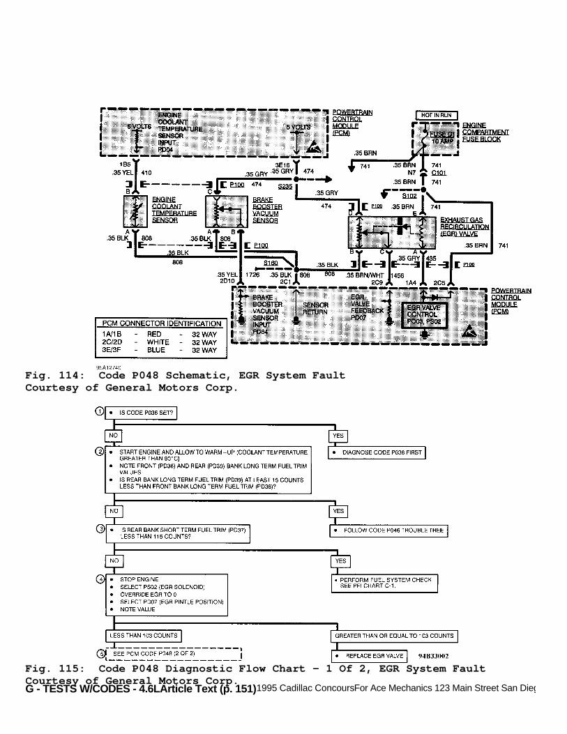
G - TESTS W/CODES - 4.6LArticle Text (p. 151)1995 Cadillac ConcoursFor Ace Mechanics 123 Main Street San Diego Ca 92126
Fig. 114: Code P048 Schematic, EGR System FaultCourtesy of General Motors Corp.
Fig. 115: Code P048 Diagnostic Flow Chart - 1 Of 2, EGR System FaultCourtesy of General Motors Corp.

G - TESTS W/CODES - 4.6LArticle Text (p. 152)1995 Cadillac ConcoursFor Ace Mechanics 123 Main Street San Diego Ca 92126
Fig. 116: Code P048 Diagnostic Flow Chart - 2 Of 2, EGR System FaultCourtesy of General Motors Corp.
CODE P051 & P108, PROM CHECKSUM MISMATCH
PCM PROM contains data essential in running engine andtransaxle. Codes P051 and P108 checks the integrity of this data. RPMis divided into 2 halves or sides in the PROM. Code P051 checks onehalf of this data and Code P108 checks the other half.Integrity of this data is checked by adding up the data in alllocations of the PROM, called the checksum. If checksum does not equalto what it should, code is set. The checksum is only checked whenignition is turned off and if it does not match, trouble code will setnext time ignition is turned on. Trouble codes can also be due to a bad connection between PCM

G - TESTS W/CODES - 4.6L
and PROM, incorrect data in PCM due to electromagnetic discharge.Faulty PROM or internal PCM problem.
NOTE: To prevent electrostatic discharge damage, DO NOT touch PCM and PROM connector pins or soldered components on circuit board.
Ensure PROM is fully inserted in socket. If PROM is fullyinserted, replace PROM. Clear memory and recheck. If Code P051 or P108reappears, replace PCM.
Fig. 117: Code P051 & P108, Prom Checksum MismatchCourtesy of General Motors Corp.
CODE P052 & P109, PCM KEEP ALIVE MEMORY RESET
This code test monitors PCM's keep alive memory for a loss orunintended change of data setting Codes P052 and P109. These codesindicate that long term memory in PCM has been reset.
Test Conditions Tested continuously.

G - TESTS W/CODES - 4.6LArticle Text (p. 154)1995 Cadillac Concours
Failure Conditions Keep alive memory checksum does not match previous checksum.
Action None.
Notes On Intermittents If battery has been disconnected for any reason, Codes P052and P109 will set. PCM keeps a running check on the memory, if memorychanges it resets. Codes P052 and P109 may also set while keying OFFin diagnostics. If IPC is sending new information to PCM when ignitionswitch is turned off, making PCM think it has been switched off,causing a reset.
Fig. 118: Code P052 & P109 Schematic, PCM Keep Alive Memory ResetCourtesy of General Motors Corp.
CODE P053, 4X REFERENCE SGNL INTERRUPT FROM IGN CNTRL MODULE
Code P053 is set if PCM does not receive 4X reference pulsesfrom Ignition Control Module (ICM) for more than .4 second. Since PFI

G - TESTS W/CODES - 4.6L
system requires ICM pulses in order to trigger injectors, mostoccurrences of Code P053 will be accompanied by a stall.
Test Conditions Code P019 and P035 not set and engine speed greater than 568RPM.
Failure Conditions No 4X reference pulses received by PCM for .4 second.
Action Code P053 is set. MIL is not illuminated.
NOTE: Test number refers to number on diagnostic chart.
1) Checks to see if Code P035 is set. A REF LO problem cancause other ignition problem. 2) Checks for power to ignition control module. 3) Checks ignition control module's ability to produce 4Xreference pulses. If system is operating correctly, reading will be 30Hertz or greater. 4) Open at fuse block. Check terminal contact. 5) Checks for open or short on circuit No. 430.
Note On Intermittents This code sets due to a false start condition which enginespeed exceeds 568 RPM but does not start.
Fig. 119: Code P053 Schematic, 4X Reference Signal Interrupt FromIgnition Control ModuleCourtesy of General Motors Corp.

G - TESTS W/CODES - 4.6LArticle Text (p. 156)1995 Cadillac Concours
Fig. 120: Code P053 Diagnostic Flow Chart, 4X Reference SignalInterrupt From Ignition Control ModuleCourtesy of General Motors Corp.
CODE P055, CLOSED TP SENSOR OUT OF RANGE

G - TESTS W/CODES - 4.6LArticle Text (p. 157)1995 Cadillac ConcoursFor Ace Mechanics 123 Main Street San Diego Ca 92126
TP sensor is self-adjusting. With ignition off, PCM executesa TP sensor learning routine. After ignition is turned off, PCM willretract ISC until ISC throttle switch opens and throttle linkage isresting on minimum air screw. PCM then stores TP sensor value andcalculates a correction. If same correction factor occurs on 2 consecutive key offcycles, TP sensor is corrected to zero degrees using correction factorlearned. If value needs correction by greater than 6.5 degrees, CodeP055 will be stored in memory at next key on cycle. Parameter PD01displays incorrect TP sensor values.
Test Conditions Tested continuously.
Failure Conditions "Learned" TP sensor is less than 6.5 degrees or greater.
Action PCM learned TP sensor value set to zero.
NOTE: Test numbers refer to numbers on diagnostic chart.
1) Checks for ISC/TP sensor codes causing Code P055 to set. 2) Checks if TP sensor is really out of range or if TP switchis open. 3) Checks TP sensor adjustment. PCM Data PD01, TP sensordisplays incorrect TP sensor so that it can be used to check TP sensoradjustment. 4) If TP sensor is within range, ISC and throttle switchoperation need to be checked. Check throttle linkage for properoperation, cruise control cable, proper throttle return springoperation and that throttle shaft and blades are free.

G - TESTS W/CODES - 4.6LArticle Text (p. 158)1995 Cadillac ConcoursFor Ace Mechanics 123 Main Street San Diego Ca 92126
Fig. 121: Code P055 Schematic, Closed TP Sensor Out Of RangeCourtesy of General Motors Corp.

G - TESTS W/CODES - 4.6LArticle Text (p. 159)1995 Cadillac ConcoursFor Ace Mechanics 123 Main Street San Diego Ca 92126
Fig. 122: Code P055 Diagnostic Flow Chart, Closed TP Sensor Out OfRangeCourtesy of General Motors Corp.
CODE P056, TRANSAXLE INPUT SPEED SENSOR CIRCUIT PROBLEM
This test checks transaxle input speed sensor circuitproblem. If engine is running and vehicle is moving at greater than 10

G - TESTS W/CODES - 4.6L
MPH, then transaxle input speed must be non-zero. If turbine speed isless than 50 MPH with vehicle speed of 10 MPH or greater, Code P056will set.
Test Conditions Codes P024, P075 and P091 not set. Transaxle not in Park orNeutral. Engine running and vehicle speed at 10 MPH or greater.
Failure Conditions PCM turns on MIL. PCM calculates transaxle input speed basedon output speed and gear ratio of gear commanded. PCM calculates slipspeed from calculated input speed and engine RPM. TCC engaged andgarage shift adapts are maintained at current levels. Torquemanagement is disabled.
NOTE: Test numbers refer to numbers on diagnostic chart.
1) With engine idling in Park or Neutral, PCM data PD72should read 50-100 RPM less than engine RPM. 2) Transaxle input speed sensor should generate a frequencyof greater than zero Hertz with engine at idle. If frequency is not asspecified, check circuits No. 1230 and 1231 and speed sensor for openor short inside transaxle. 3) Checks circuits No. 1230 and 1231 for open or short toPCM. If circuit is okay, PCM is faulty.
Note On Intermittents Manipulate circuits No. 1230 and 1231. Look for EMI sources,such as sensor wires running along spark plug cables or high powertransmitters in vicinity.
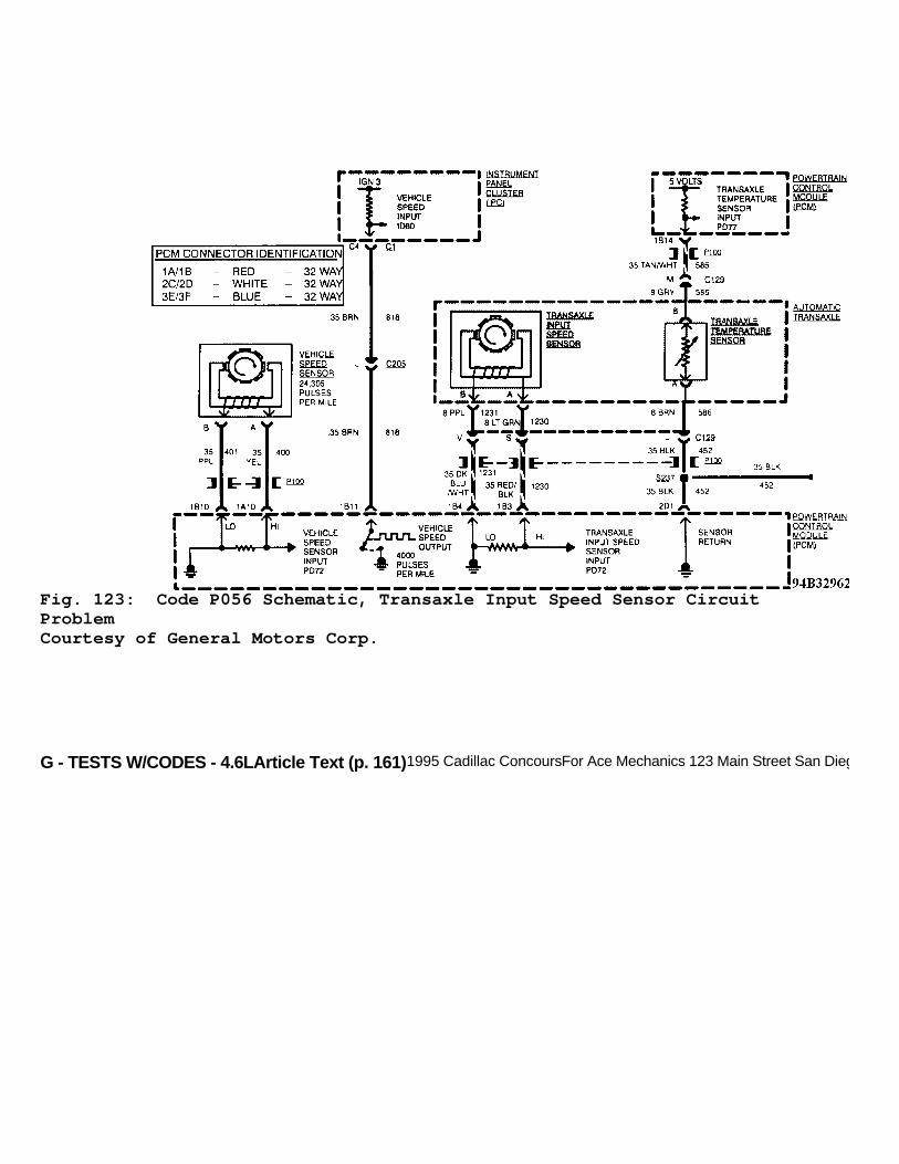
G - TESTS W/CODES - 4.6LArticle Text (p. 161)1995 Cadillac ConcoursFor Ace Mechanics 123 Main Street San Diego Ca 92126
Fig. 123: Code P056 Schematic, Transaxle Input Speed Sensor CircuitProblemCourtesy of General Motors Corp.

G - TESTS W/CODES - 4.6LArticle Text (p. 162)1995 Cadillac ConcoursFor Ace Mechanics 123 Main Street San Diego Ca 92126
Fig. 124: Code P056 Diagnostic Flow Chart, Transaxle Input SpeedSensor Circuit ProblemCourtesy of General Motors Corp.
CODE P057, SHORTED TRANSAXLE TEMPERATURE SENSOR CIRCUIT
Transaxle temperature sensor resistance decreases as sensortemperature increases. A high transaxle temperature will result in lowsignal voltage on circuit No. 585 (Tan/White wire). Code P057 setswhen PCM sees a transaxle temperature reading of 298øF (148øC) orgreater (.08 volt or less).
Test Conditions Test continuously.
Failure Conditions Transaxle temperature sensor value at 298øF (148øC) orgreater for 5 seconds.
Action

G - TESTS W/CODES - 4.6LArticle Text (p. 163)1995 Cadillac ConcoursFor Ace Mechanics 123 Main Street San Diego Ca 92126
PCM turns on SERVICE VEHICLE SOON message. PCM substitutesengine coolant temperature value for transaxle temperature untilengine coolant temperature reaches 221øF (105øC) before it sets to hotmode operation. Transaxle shift adapts and garage shift adapts aremaintained in current levels.
NOTE: Test numbers refer to numbers on diagnostic chart.
1) If transaxle temperature sensor is shorted, PCM dataparameter PD77 should read 298øF (148øC) or greater. If parameter doesnot show this reading, sensor and wiring are okay. 2) Checks if circuit No. 585 (Tan/White wire) is shorted. Ifparameter value stays at -18øF (-28øC) or greater with transaxletemperature sensor connector disconnected, check for short betweensensor connector and PCM terminal No. 1B14. 3) Checks for short to ground on circuit No. 585 (Tan/Whitewire) inside transaxle. If wire is okay, replace shorted transaxletemperature sensor.
Fig. 125: Code P057 Schematic, Shorted Transaxle Temp. Sensor CircuitCourtesy of General Motors Corp.

G - TESTS W/CODES - 4.6LArticle Text (p. 164)1995 Cadillac ConcoursFor Ace Mechanics 123 Main Street San Diego Ca 92126
Fig. 126: Code P057 Diagnostic Flow Chart, Shorted Transaxle Temp.Sensor Ckt.Courtesy of General Motors Corp.
CODE P058, PASS-KEY(R) FUEL ENABLE PROBLEM
PASS-Key(R) system enables engine operation by allowingstarter to engage and issuing a fuel enable signal to PCM. Once engineis running, PCM constantly monitors fuel enable signal from PASS-Key(R) module. PCM will not cancel fuel injection once it has seen aproper PASS-Key(R) module signal; therefore, stalling conditionscannot occur as a result of a PASS-Key(R) malfunction.
Test Conditions Engine has been running for a predetermined amount of time.PASS-Key(R) engine start timer expired.
Failure Conditions PASS-Key(R) fuel enable input incorrect but has been correctwithin this engine run cycle.
Action "THEFT SYSTEM PROBLEM, CAR MAY NOT RESTART" message isdisplayed on DIC. Enables fuel injection on future ignition cycles

G - TESTS W/CODES - 4.6L
without regard for PASS-Key(R) fuel enable input status.
NOTE: Test numbers refer to numbers on diagnostic chart.
1) If engine will crank, problem has been isolated to PASS-Key(R) module, PCM or fuel enable circuit. If engine will not crank,perform PASS-Key(R) system diagnosis. See PASS-KEY(R) DIAGNOSIS. 2) Checking voltage to PCM will identify if PCM is at fault.Typical signal will be about 2-3 volts. 3) Checks if PCM is recognizing cranking fuel enable signalfrom PASS-Key(R) decoder module. 4) Checks circuit No. 229 for short or open circuit. Ifcircuit is okay, check PASS-Key(R) module terminal contacts.
Note On Intermittents If code is intermittent, check forshort to ground or voltage on circuit No. 229, intermittent open incircuit No. 229 or intermittent loss of power to module.
PASS-Key(R) Diagnosis PASS-Key(R) system interfaces PCM and starter with a powersource, decoder module, starter enable relay, ignition switch andinstrument cluster. Before replacing PASS-Key(R) module, check systemfor following common problems.
* Check ignition key pellet sensing contacts in ignition lock cylinder. Look into cylinder lock. If contacts are damaged, replace cylinder lock. * Check PASS-Key(R), PCM and GAGES fuses. * Check SECURITY indicator bulb in instrument panel. * A defective resistor pellet within ignition key or incorrect resistance value of key (15 different assigned values) will cause vehicle not to start. Key must be correct electrically and mechanically.
If incorrect key is used to try to start vehicle, decoderwill not allow vehicle to start for 2-4 minutes, even if after correctkey is inserted.

G - TESTS W/CODES - 4.6LArticle Text (p. 166)1995 Cadillac ConcoursFor Ace Mechanics 123 Main Street San Diego Ca 92126
Fig. 127: Code P058 Schematic, Pass-Key(R) Fuel Enable ProblemCourtesy of General Motors Corp.

G - TESTS W/CODES - 4.6LArticle Text (p. 167)1995 Cadillac ConcoursFor Ace Mechanics 123 Main Street San Diego Ca 92126
Fig. 128: Code P058 Diag. Flow Chart, Pass-Key(R) Fuel Enable ProblemCourtesy of General Motors Corp.
CODE P059, OPEN TRANSAXLE TEMPERATURE SENSOR CIRCUIT
Transaxle temperature sensor resistance varies based on itsresistance. As sensor temperature increases, resistance decreases. Alow transaxle temperature will result in high voltage in circuit No.585. Code P059 sets when PCM sees a transaxle temperature sensorreading of -31øF(-35øC) or less (4.9 volts or greater).
Test Conditions Codes P014, P015 and P024 not set. Coolant temperature at

G - TESTS W/CODES - 4.6L
-13.0øF (-25øC) or greater and vehicle speed greater than zero MPH.
Failure Conditions Transaxle temperature sensor at -32øF (-36øC) or less for 6seconds.
Action PCM turns on MIL. PCM substitutes coolant temperature valuefor transaxle temperature until coolant temperature reaches 221øF(105øC) then transaxle will be set to hot mode operation.
NOTE: Test numbers refer to numbers on diagnostic chart.
1) With transaxle temperature sensor or wiring open, PCM dataPD77 will read -35øC or less. If parameter does not show this, sensorand circuit is okay. 2) Check for open in circuit No. 585 between PCM and sensorconnector. If PCM data PD77 reads 148-151øC with sensor terminal "M"jumpered to ground, the circuit No. 585 and PCM are okay. 3) Checks circuit No. 452 for open to PCM terminal connector. 4) Checks PCM's ability to recognize low voltage on PCMterminal 1B14 (transaxle temperature sensor input). If grounding PCMterminal 1B14 caused PCM data PD77 to read 148-151øC, check for openin circuit No. 585 between PCM and sensor connector. 5) Checks for open transaxle temperature sensor.
Fig. 129: Code P059 Schematic, Open Transaxle Temperature SensorCircuitCourtesy of General Motors Corp.

G - TESTS W/CODES - 4.6LArticle Text (p. 169)1995 Cadillac Concours
Fig. 130: Code P059 Diagnostic Flow Chart, Open Transaxle TemperatureSensor CircuitCourtesy of General Motors Corp.
CODE P060, CRUISE CONTROL WITH TRANSAXLE NOT IN DRIVE
Code P060 sets if cruise control is engaged and park/neutralswitch is closed, indicating transaxle is in Park or Neutral.
Test Conditions Cruise control on and engaged.
Failure Conditions Transaxle in Park or Neutral.
Action PCM disengages cruise control.
NOTE: Test numbers refer to numbers on diagnostic chart.

G - TESTS W/CODES - 4.6LArticle Text (p. 170)1995 Cadillac ConcoursFor Ace Mechanics 123 Main Street San Diego Ca 92126
1) Checks if Code P028 or P091 are set because they can causeCode P060 to set. 2) Checks if P/N input to PCM from transaxle range switchagrees with transaxle pressure switch. If they do, code was driverinduced by shifting into Park or Neutral while cruise control wasengaged. If not, check for intermittent fault.
Fig. 131: Code P060 Schematic, Cruise Control With Transaxle Not InDriveCourtesy of General Motors Corp.

G - TESTS W/CODES - 4.6LArticle Text (p. 171)1995 Cadillac ConcoursFor Ace Mechanics 123 Main Street San Diego Ca 92126
Fig. 132: Code P060 Diagnostic Flow Chart, Cruise Control WithTransaxle Not In DriveCourtesy of General Motors Corp.
CODE P061, CRUISE CONTROL VENT SOLENOID PROBLEM
Code P061 will set if PCM output PO07 is commanding ventsolenoid off and feedback is indicating that it is on or PCM iscommanding vent solenoid on and feedback is indicating that it is offfor 0.5 second.
Test Conditions Tested continuously.
Failure Conditions Cruise vent solenoid commanded off but feedback indicatessolenoid is on or cruise vent solenoid commanded on but feedbackindicates solenoid is off.
Action PCM disables cruise control.
NOTE: Test numbers refer to numbers on diagnostic chart.

G - TESTS W/CODES - 4.6LArticle Text (p. 172)1995 Cadillac ConcoursFor Ace Mechanics 123 Main Street San Diego Ca 92126
1) Checks to see if fault is due to cruise control servo orcircuit. Frequency should cycle between zero and a non-zero number. IfDVOM stays at zero, circuit or PCM is at fault. 2) Checks for short to voltage in circuit No. 403. 3) Checks for open in circuit No. 451. 4) Checks PCM's ability to control cruise control servo.Voltage should cycle between zero and 12 volts. If voltage does notcycle, check for open in circuit No. 403.
Fig. 133: Code P061 Schematic, Cruise Control Vent Solenoid ProblemCourtesy of General Motors Corp.

G - TESTS W/CODES - 4.6LArticle Text (p. 173)1995 Cadillac ConcoursFor Ace Mechanics 123 Main Street San Diego Ca 92126Fig. 134: Code P061 Diagnostic Flow Chart, Cruise Control VentSolenoid ProblemCourtesy of General Motors Corp.
CODE P062, CRUISE CONTROL VACUUM SOLENOID PROBLEM
Code P062 will set if PCM output PO08 is commanding vacuumsolenoid off and feedback is indicating that it is on, or PCM iscommanding vacuum solenoid on and feedback is indicating that it isoff for 0.5 second.
Test Conditions Tested continuously.

G - TESTS W/CODES - 4.6LArticle Text (p. 174)1995 Cadillac Concours
Failure Conditions Cruise vacuum solenoid commanded off but feedback indicatessolenoid is on, or cruise vacuum solenoid commanded on but feedbackindicates solenoid is off.
Action PCM disables cruise control.
NOTE: Test numbers refer to numbers on diagnostic chart.
1) Checks if fault is due to cruise control servo or circuit.Frequency should cycle between zero and a non-zero number. If DVOMstays at zero, circuit or PCM is at fault. 2) Checks for short to voltage in circuit No. 205. 3) Checks for open in circuit No. 451. 4) Checks PCM's ability to control cruise control servo.Voltage should cycle between zero and 12 volts. If voltage does notcycle, check circuit No. 205 for open.
Fig. 135: Code P062 Schematic, Cruise Control Vacuum Solenoid ProblemCourtesy of General Motors Corp.

G - TESTS W/CODES - 4.6LArticle Text (p. 175)1995 Cadillac ConcoursFor Ace Mechanics 123 Main Street San Diego Ca 92126
Fig. 136: Code P062 Diagnostic Flow Chart, Cruise Control VacuumSolenoid ProblemCourtesy of General Motors Corp.
CODE P063, VEHICLE SPEED & SET SPEED DIFFERENCE TOO HIGH
Code P063 will set and disengage cruise control if vehiclespeed is 20 MPH greater than cruise set speed. Code P063 is designedto detect a cruise control problem that results in cruise overspeed orinability to hold speed.
Test Conditions

G - TESTS W/CODES - 4.6LArticle Text (p. 176)1995 Cadillac ConcoursFor Ace Mechanics 123 Main Street San Diego Ca 92126
Tested when cruise control is enabled and engaged, andcruise control servo position is at 39 percent or greater.
Failure Conditions Vehicle speed 20 MPH greater than set speed for .5 second.
Action PCM disengages cruise control.
NOTE: Test numbers refer to numbers on diagnostic chart.
1) If Code P075 is set, diagnose code first because it cancause other speed related problems. 2) Checks if cruise control feedback is a value is zero to 6or greater. 3) Checks if PCM and related circuit to cruise control servois okay (4.6-5.1 volts). 4) Checks if circuit No. 398 for a short to voltage. 5) Checks if cruise control servo is able to respondcorrectly to signal from PCM.
Notes On Intermittents If Code P063 is intermittent, ensure vehicle operator is notoverrunning set speed by greater than 20 MPH. Trouble code will notset by vacuum leaks or vacuum supply problem. Trouble code can only beset by vehicle exceeding set speed by 20 MPH.
Fig. 137: Code P063 Schematic, Vehicle Speed & Set Speed DifferenceToo HighCourtesy of General Motors Corp.
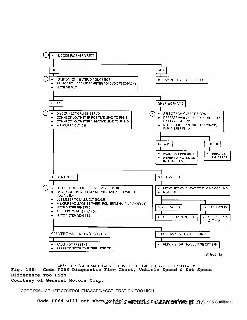
G - TESTS W/CODES - 4.6LArticle Text (p. 177)1995 Cadillac Concours
Fig. 138: Code P063 Diagnostic Flow Chart, Vehicle Speed & Set SpeedDifference Too HighCourtesy of General Motors Corp.
CODE P064, CRUISE CONTROL ENGAGED/ACCELERATION TOO HIGH
Code P064 will set when vehicle speed is increasing at a

G - TESTS W/CODES - 4.6L
rapid rate (wheel spin). This protective measure prevents wheel spinon icy roads when cruise control is in operation.
Test Conditions Tested continuously.
Failure Conditions Vehicle speed increases greater than 16 MPH in one secondwith cruise control engaged. Cruise control disengages when code sets.Code sets when wheel spins due to slippery conditions.
Action PCM disengages cruise control. If Code PO64 is present and noother cruise control faults exists, clear code and road test vehicle.If Code P075 is also present, check for sources of ElectromagneticInterference (EMI) such as VSS wire running along spark plug cables orhigh power transmitters, like mobile radios, operating in vicinity.
Fig. 139: Code P064 Schematic, Cruise Control Engaged/AccelerationToo HighCourtesy of General Motors Corp.
CODE P065, CRUISE CONTROL SERVO POSITION SENSOR FAILURE
Cruise servo position sensor is a potentiometer that changes

G - TESTS W/CODES - 4.6L
resistance with servo position. Code P065 sets when PCM detects a lowvoltage, indicating a short to ground in cruise servo position sensorcircuit.
Test Conditions Tested continuously.
Failure Conditions Cruise control servo position 1.9 percent or less for 0.9second.
Action PCM disables cruise control.
NOTE: Test numbers refer to numbers on diagnostic chart.
1) Checks if cruise control feedback is a value that itshould never be, even with servo fully released (0-2). 2) Checks PCM and circuit to cruise control servo are okay.Voltage reading should be 4.6-5.1 volts. 3) Checks circuit No. 399 for an open. 4) Checks circuit No. 398 for an open. 5) Checks circuit No. 398 for short to ground. If wire isokay, PCM is open internally. 6) Checks if cruise control servo is operating normally. Iffeedback is greater than 30, servo is operating correctly.
Fig. 140: Code P065 Schematic, Cruise Control Servo Position SensorFailureCourtesy of General Motors Corp.
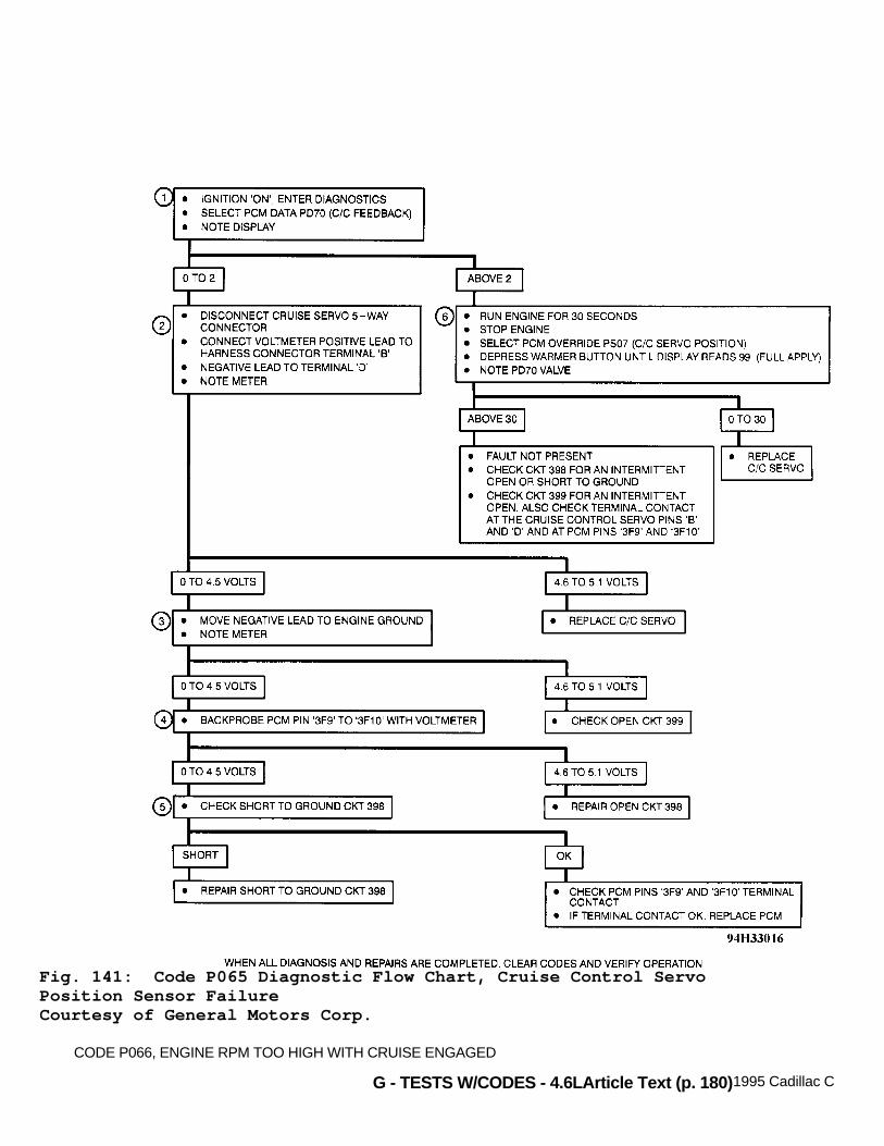
G - TESTS W/CODES - 4.6LArticle Text (p. 180)1995 Cadillac Concours
Fig. 141: Code P065 Diagnostic Flow Chart, Cruise Control ServoPosition Sensor FailureCourtesy of General Motors Corp.
CODE P066, ENGINE RPM TOO HIGH WITH CRUISE ENGAGED

G - TESTS W/CODES - 4.6LArticle Text (p. 181)1995 Cadillac ConcoursFor Ace Mechanics 123 Main Street San Diego Ca 92126
Code P066 will set when engine speed is greater than 5975 RPMwith cruise engaged. This may occur on slippery pavement, extendedwide open throttle acceleration or for some other mechanical problems(such as transaxle slippage). Under these conditions, Code P066 isnormal. Vehicle operator should be advised why cruise control de-energized. Clear code, and road test vehicle to verify normaloperation.
Test Conditions Cruise is enabled and engaged. Vehicle operator not manuallycontrolling throttle position.
Failure Conditions Engine at 5975 RPM or greater for 0.5 second with cruisecontrol on and engaged. This may occur on slippery road conditions,extended wide open throttle acceleration or for some mechanicalproblems, such as transaxle slippage. Under these conditions Code P066will set. This should be considered normal for cruise control todisengage. Clear code and road test vehicle to verify normaloperation.
Action PCM disengages cruise control.
Fig. 142: Code P066 Schematic, Engine RPM Too High With CruiseEngagedCourtesy of General Motors Corp.

G - TESTS W/CODES - 4.6LArticle Text (p. 182)1995 Cadillac Concours
CODE P067, SET/COAST OR RESUME/ACCEL SWITCH SHORTED
When cruise control is on, system voltage is available at oneside of normally open contact of SET/COAST and RESUME/ACCEL switches.If cruise control switch is in ON position, voltage is available toswitches when ignition is turned on. If SET/COAST or RESUME/ACCELswitches were stuck on or shorted to power, cruise control operationwould begin. To prevent this, Code P067 will set and cruise controloperation is disabled if signal voltage from SET/COAST (circuit No.84) or RESUME/ACCEL (circuit No. 87) is high continuously for 10minutes. Cruise control will be disengaged until PCM sees a lowvoltage on both of these signals.
Test Conditions Tested continuously.
Failure Conditions SET/COAST and RESUME/ACCEL switches are both closed for 10minutes.
Action PCM disengages cruise control.
NOTE: Test numbers refer to numbers on diagnostic chart.
1) Checks if PCM input data PI83 (SET/COAST) and PI84(RESUME/ACCEL) will cycle from LO to HI to LO. If inputs remain high,a short to voltage in system is present. 2) Checks if SET/COAST and/or RESUME/ACCEL switches areshorted to voltage. 3) Checks if circuit No. 84 is shorted to voltage. 4) Checks if circuit No. 87 is shorted to voltage.

G - TESTS W/CODES - 4.6LArticle Text (p. 183)1995 Cadillac ConcoursFor Ace Mechanics 123 Main Street San Diego Ca 92126
Fig. 143: Code P067 Schematic, Set/Coast Or Resume/Accelerator SwitchShortedCourtesy of General Motors Corp.
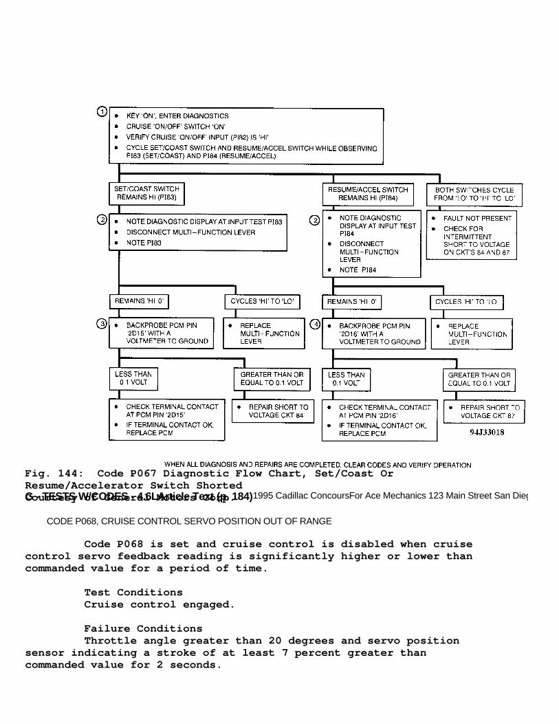
G - TESTS W/CODES - 4.6LArticle Text (p. 184)1995 Cadillac ConcoursFor Ace Mechanics 123 Main Street San Diego Ca 92126
Fig. 144: Code P067 Diagnostic Flow Chart, Set/Coast OrResume/Accelerator Switch ShortedCourtesy of General Motors Corp.
CODE P068, CRUISE CONTROL SERVO POSITION OUT OF RANGE
Code P068 is set and cruise control is disabled when cruisecontrol servo feedback reading is significantly higher or lower thancommanded value for a period of time.
Test Conditions Cruise control engaged.
Failure Conditions Throttle angle greater than 20 degrees and servo positionsensor indicating a stroke of at least 7 percent greater thancommanded value for 2 seconds.
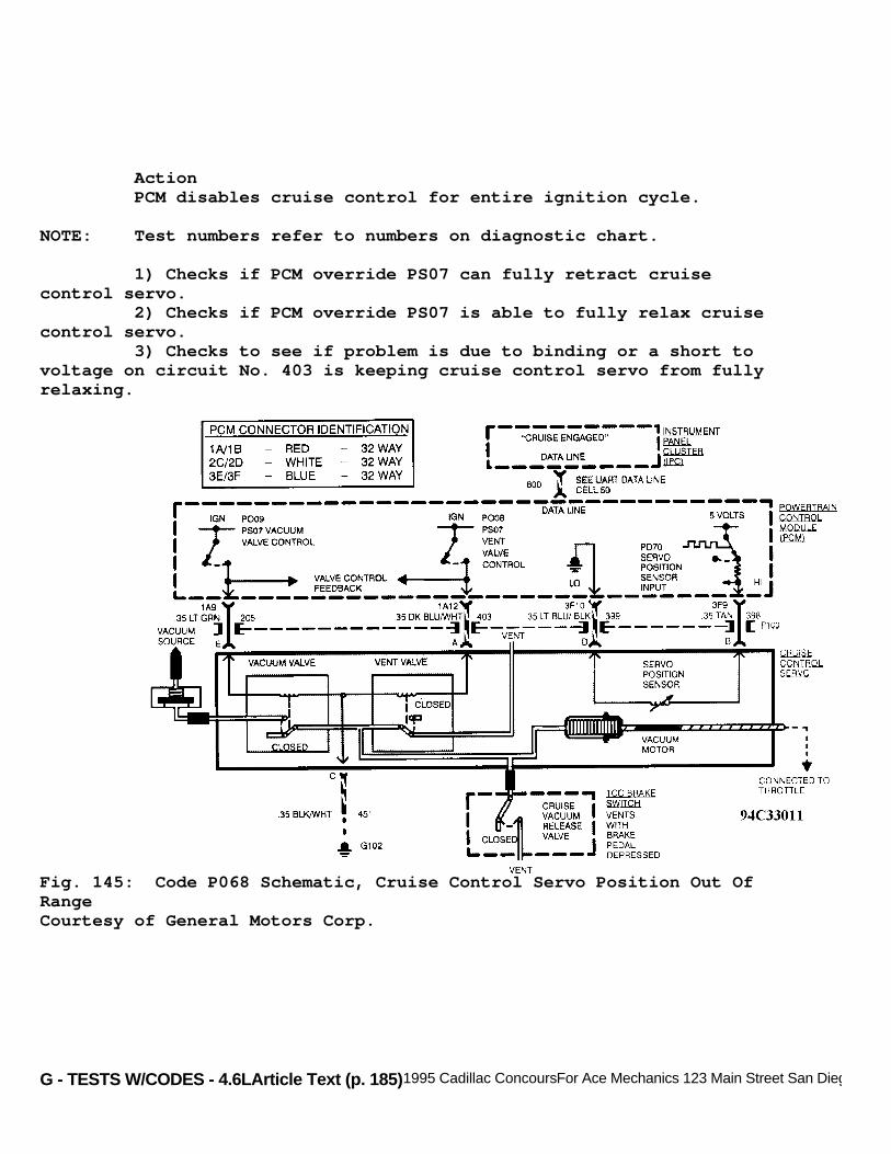
G - TESTS W/CODES - 4.6LArticle Text (p. 185)1995 Cadillac ConcoursFor Ace Mechanics 123 Main Street San Diego Ca 92126
Action PCM disables cruise control for entire ignition cycle.
NOTE: Test numbers refer to numbers on diagnostic chart.
1) Checks if PCM override PS07 can fully retract cruisecontrol servo. 2) Checks if PCM override PS07 is able to fully relax cruisecontrol servo. 3) Checks to see if problem is due to binding or a short tovoltage on circuit No. 403 is keeping cruise control servo from fullyrelaxing.
Fig. 145: Code P068 Schematic, Cruise Control Servo Position Out OfRangeCourtesy of General Motors Corp.
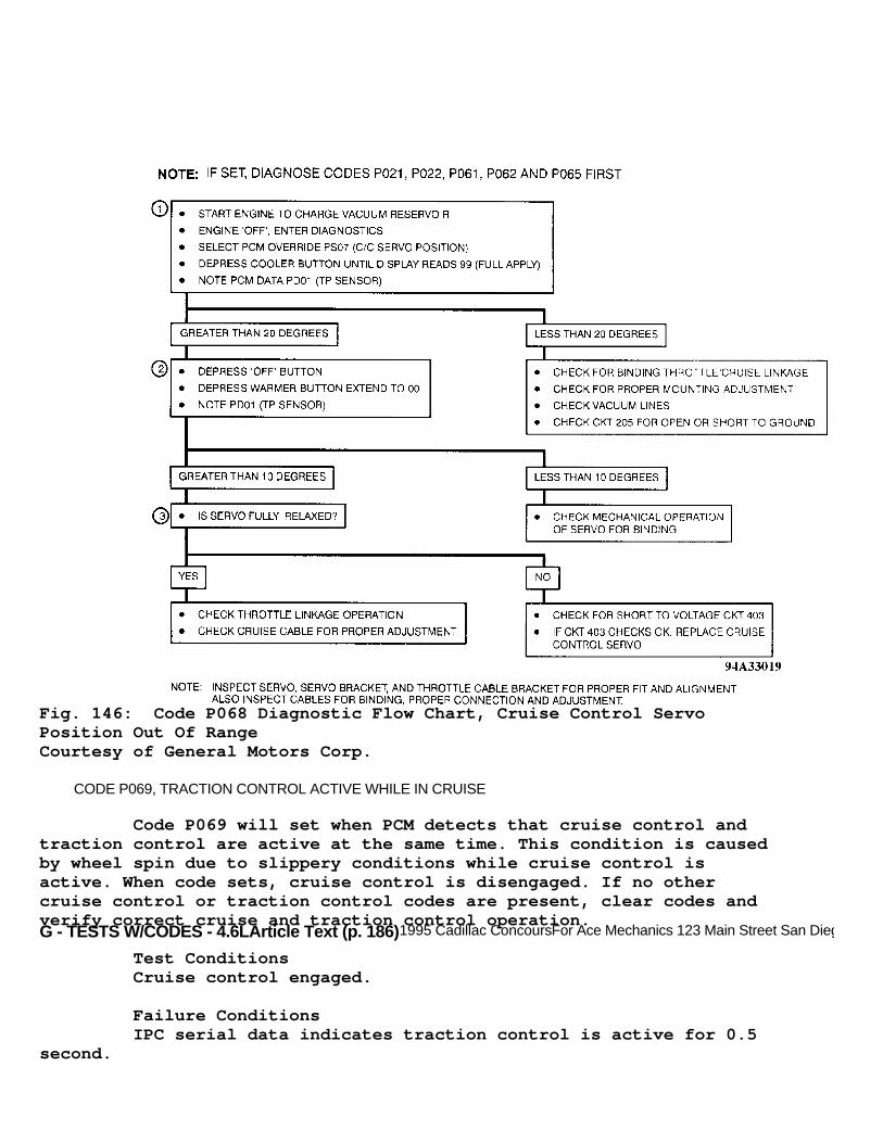
G - TESTS W/CODES - 4.6LArticle Text (p. 186)1995 Cadillac ConcoursFor Ace Mechanics 123 Main Street San Diego Ca 92126
Fig. 146: Code P068 Diagnostic Flow Chart, Cruise Control ServoPosition Out Of RangeCourtesy of General Motors Corp.
CODE P069, TRACTION CONTROL ACTIVE WHILE IN CRUISE
Code P069 will set when PCM detects that cruise control andtraction control are active at the same time. This condition is causedby wheel spin due to slippery conditions while cruise control isactive. When code sets, cruise control is disengaged. If no othercruise control or traction control codes are present, clear codes andverify correct cruise and traction control operation.
Test Conditions Cruise control engaged.
Failure Conditions IPC serial data indicates traction control is active for 0.5second.

G - TESTS W/CODES - 4.6LArticle Text (p. 187)1995 Cadillac ConcoursFor Ace Mechanics 123 Main Street San Diego Ca 92126
Action PCM disables cruise control.
Fig. 147: Code P069 Schematic, Traction Control Active While InCruiseCourtesy of General Motors Corp.
CODE P070, INTERMITTENT THROTTLE POSITION (TP) SENSOR SIGNAL
This test monitors MAP and TP sensors. Code P070 will set ifMAP value remains constant and TP sensor value changes considerably.Engine operation requires that any large change in TP sensor valuemust be followed by a change in MAP sensor value.
Test Conditions Codes P031, P032 and P034 not set. Throttle angle changesmore than 5 degrees in 12.5 milliseconds (.0125 seconds). Engine notdecelerating (MAP drops to 22 kPa or less). Engine not accelerating(MAP is within 7.4 kPa of atmospheric pressure). Engine running.Coolant level normal and engine not overheating. Traction control notactive.
Failure Conditions MAP changes 3 kPa or less in .21 second following a 5 degreeor greater change in throttle angle.

G - TESTS W/CODES - 4.6LArticle Text (p. 188)1995 Cadillac Concours
Action None.
NOTE: Test number refers to number on diagnostic chart. Reference to CHART 3 refers to POWERTRAIN CHARTS.
1) Checking Code P070 snapshot value is used to determine ifan intermittent low or high voltage caused code to set. Anintermittent low voltage can be caused by an open or short to groundin circuit No. 417, an open in circuit No. 474 or a faulty TP sensor.An intermittent high voltage can be caused by an open in circuit No.808 or a short to voltage on circuit No. 417.
Fig. 148: Code P070 Schematic, Intermittent Throttle Position (TP)Sensor SignalCourtesy of General Motors Corp.
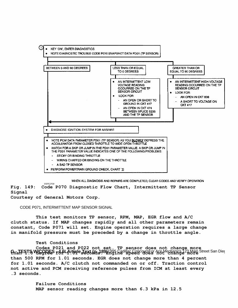
G - TESTS W/CODES - 4.6LArticle Text (p. 189)1995 Cadillac ConcoursFor Ace Mechanics 123 Main Street San Diego Ca 92126
Fig. 149: Code P070 Diagnostic Flow Chart, Intermittent TP SensorSignalCourtesy of General Motors Corp.
CODE P071, INTERMITTENT MAP SENSOR SIGNAL
This test monitors TP sensor, RPM, MAP, EGR flow and A/Cclutch status. If MAP changes rapidly and all other parameters remainconstant, Code P071 will set. Engine operation requires a large changein manifold pressure must be preceded by a change in throttle angle.
Test Conditions Codes P021 and P022 not set. TP sensor does not change morethan 1.0 degree for 1.01 seconds. Engine speed does not change morethan 500 RPM for 1.01 seconds. EGR does not change more than 4 percentfor 1.01 seconds. A/C clutch not commanded on or off. Traction controlnot active and PCM receiving reference pulses from ICM at least every.3 seconds.
Failure Conditions MAP sensor reading changes more than 6.3 kPa in 12.5

G - TESTS W/CODES - 4.6L
milliseconds (.0125 second).
Action PCM uses substitute MAP value based on engine RPM andthrottle position switch status.
NOTE: Test numbers refer to numbers on diagnostic chart. Reference to CHART 3 refers to POWERTRAIN CHARTS.
1) Checks if MAP can read BARO pressure correctly (87-105kPa). 2) Checks MAP sensor's ability to react to a known vacuum(26-34 kPa). 3) Checks MAP sensor's ability to react to sudden change invacuum.
Fig. 150: Code P071 Schematic - 1 Of 2, Intermittent MAP SensorSignalCourtesy of General Motors Corp.

G - TESTS W/CODES - 4.6LArticle Text (p. 191)1995 Cadillac ConcoursFor Ace Mechanics 123 Main Street San Diego Ca 92126
Fig. 151: Code P071 Schematic - 2 Of 2, Intermittent MAP SensorSignalCourtesy of General Motors Corp.
Fig. 152: Code P071 Diag. Flow Chart, Intermittent MAP Sensor SignalCourtesy of General Motors Corp.
G - TESTS W/CODES - 4.6LArticle Text (p. 192)1995 Cadillac ConcoursFor Ace Mechanics 123 Main Street San Diego Ca 92126
CODE P073, INTERMITTENT ENGINE COOLANT TEMP SENSOR SIGNAL
Engine Coolant Temperature (ECT) sensor circuit uses 2 pull-up resistors for temperature sensing. When sensor resistance is high(indicating low temperatures), PCM uses 3.65-k/ohm resistor and 348-ohm resistor in series. As temperature increases to 122øF (50øC),sensor resistance will decrease to 973 ohms. This resistancecorresponds to .97 volt at PCM. At this point PCM shifts to single348-ohm pull-up resistor to measure temperature greater than 122øF(50øC). PCM monitors voltage signal of circuit and assumes engineoperation causes coolant temperatures to change at slow rates. Thistest monitors ECT sensor voltage. If PCM detects a large change insensor output voltage in a one-second period, code will set.
Test Conditions Two seconds have passed since ignition has been turned onand 2 seconds have passed since PCM had shifted ECT sensor pull-upresistors. This occurs when sensor resistance indicates 122øF (50øC).
Failure Conditions ECT sensor voltage changes .3 volt in one second.
Action Code P073 is set. No service message is given.
NOTE: Test number refers to number on diagnostic chart. Reference to CHART 3 refers to POWERTRAIN CHARTS.
1) Checks Code P073 snapshot value to determine if anintermittent high or low resistance caused code to set. Anintermittent high resistance can be caused by an open in circuit No.410 or 808. An intermittent low resistance can be caused by a short toground in circuit No. 410.

G - TESTS W/CODES - 4.6LArticle Text (p. 193)1995 Cadillac ConcoursFor Ace Mechanics 123 Main Street San Diego Ca 92126
Fig. 153: Code P073 Schematic, Intermittent Engine CoolantTemperature Sensor SignalCourtesy of General Motors Corp.

G - TESTS W/CODES - 4.6LArticle Text (p. 194)1995 Cadillac ConcoursFor Ace Mechanics 123 Main Street San Diego Ca 92126
Fig. 154: Code P073 Diagnostic Flow Chart, Intermittent EngineCoolant Temperature Sensor SignalCourtesy of General Motors Corp.
CODE P074, INTERMITTENT IAT SENSOR SIGNAL
Code P074 will set when PCM detects a large change in sensoroutput voltage in a .3-second period of time.
Test Conditions Two seconds have passed since ignition switch has been

G - TESTS W/CODES - 4.6L
turned to RUN position.
Failure Conditions IAT sensor voltage changes .3 volt (11øC) in 250milliseconds.
Action None.
NOTE: Test number refers to number on diagnostic chart. Reference to CHART 3 refers to POWERTRAIN CHARTS.
1) Checks Code P074 snapshot to determine if an intermittenthigh or low resistance caused code to set. An intermittent highresistance can be caused by an open in circuit No. 452 or 472. Anintermittent low resistance can be caused by a short to ground oncircuit No. 472.
Fig. 155: Code P074 Schematic, Intermittent IAT Sensor SignalCourtesy of General Motors Corp.

G - TESTS W/CODES - 4.6LArticle Text (p. 196)1995 Cadillac ConcoursFor Ace Mechanics 123 Main Street San Diego Ca 92126
Fig. 156: Code P074 Diagnostic Flow Chart, Intermittent IAT SensorSignalCourtesy of General Motors Corp.
CODE P075, VSS SIGNAL INTERRUPT
This test compares vehicle speed to manifold pressure. Changein MAP must correspond with a change in vehicle speed. PCM will ignoretest if conditions for engine idle are present. If vehicle speedchanges 14 MPH (VIN Y) or 16 MPH (VIN 9) or greater in one second CodeP075 will set. If failure occurs 10 times in 10 seconds, code willremain current for the entire ignition cycle.
Test Conditions Codes P021, P022, P027, P056 and P090 not set. TCC brakeswitch not applied. Engine running at 500 RPM or greater. Two secondshave passed since ignition was turned on. Traction control not active.Throttle position 15.7 degrees or greater.
Failure Conditions Vehicle speed change of 4 MPH or more in a one-second timeperiod.
Action PCM turns on MIL, disables TCC and freezes transaxle incurrent gear. If failure occurs 10 times in 10 seconds, code will

G - TESTS W/CODES - 4.6L
remain current for the entire ignition cycle.
Fig. 157: Code P075 Schematic, VSS Signal InterruptCourtesy of General Motors Corp.
CODE P076, TRANSAXLE PRESSURE CONTROL SOLENOID CIRCUIT
Transaxle pressure control solenoid regulates pressure tomaintain a desired transaxle line pressure under varying operatingconditions. PCM send a pulse width modulated signal to transaxlepressure control solenoid in order to control line pressure.A PCM internal current monitor is provided as feedback to determineactual transaxle pressure control solenoid current draw. Current drawis proportional to transaxle line pressure. If commanded versus actualcurrent draw is different by more than calibrated value or iftransaxle pressure control solenoid is energized at 100 percent dutycycle for 3 minutes or more, Code P076 will set.
Test Conditions Codes P016, P086 and P089 not set. Engine running.
Failure Conditions Difference between commanded and actual transaxle pressurecontrol solenoid current .16 amps or greater for one second ortransaxle pressure solenoid energized at 100 percent duty cycle for 3minutes or more.

G - TESTS W/CODES - 4.6LArticle Text (p. 198)1995 Cadillac ConcoursFor Ace Mechanics 123 Main Street San Diego Ca 92126
Action PCM turns on MIL, transaxle pressure control solenoid de-energized. Torque management disabled and transaxle shift adapts aremaintained at current levels.
NOTE: Test number refers to number on diagnostic chart.
1) Checks for open in transaxle pressure control solenoidcircuit. If resistance is 8 ohms or greater, circuit is open. 2) Checks for short to ground in transaxle pressure controlsolenoid circuit. If resistance is 100 ohms or less, circuit isshorted to ground. 3) If transaxle pressure control solenoid is okay, fault iseither intermittent or PCM is faulty. 4) If resistance is greater than 8 ohms, check for opentransaxle pressure control solenoid or circuits No. 1228 or 1229. Ifresistance is 8 ohms or less, check for open between solenoidconnector and PCM in circuits No. 1228 or 1229. 5) If resistance is 100 ohms or greater, check for short toground between PCM connector circuits NO. 1228 or 1229. If resistanceis less than 100 ohms, check for short to ground inside transaxlecircuits No. 1228 or 1229 or for shorted transaxle pressure solenoid.
Fig. 158: Code P076 Schematic, Transaxle Pressure Control SolenoidCircuitCourtesy of General Motors Corp.

G - TESTS W/CODES - 4.6LArticle Text (p. 199)1995 Cadillac Concours
Fig. 159: Code P076 Diagnostic Flow Chart, Transaxle Pressure ControlSolenoid CircuitCourtesy of General Motors Corp.
CODE P080, TP SENSOR/IDLE LEARN NOT COMPLETE

G - TESTS W/CODES - 4.6LArticle Text (p. 200)1995 Cadillac ConcoursFor Ace Mechanics 123 Main Street San Diego Ca 92126
This test checks if initial TP sensor learn and idle learnvalues have been stored in PCM. If these values have not been stored,Code P080 is set. Performing TP sensor/idle learn procedure will causeCode P080 to become history.
Test Conditions Tested continuously.
Failure Conditions No TP sensor or idle learn value stored.
Actions PCM turns on MIL.
Fig. 160: Code P080 Schematic, TP Sensor/Idle Learn Not CompleteCourtesy of General Motors Corp.

G - TESTS W/CODES - 4.6LArticle Text (p. 201)1995 Cadillac ConcoursFor Ace Mechanics 123 Main Street San Diego Ca 92126
Fig. 161: Code P080 Diag. Flow Chart, TP Sensor/Idle Learn NotCompleteCourtesy of General Motors Corp.
CODE P081, CAM TO 4X REFERENCE CORRELATION PROBLEM
This test checks to see if there are eight 4X referencepulses between cam signals. Code P081 will set when this signal is notpresent. DO NOT attempt diagnosis or repair unless vehicle operator isexperiencing driveability problems associated with this code.
Test Conditions Code P035 not set, engine speed greater than 496 RPM and 7or greater cam pulses after ignition was turned on.
Failure Conditions Number of 4X reference pulses between cam pulses is notequals to 8. Failure must exist continuously for 2 or more cycles.

G - TESTS W/CODES - 4.6L
Action None.
Fig. 162: Code P081 Schematic, CAM To 4X Reference CorrelationProblemCourtesy of General Motors Corp.
Fig. 163: Code P081 Schematic, CAM To 4X Reference CorrelationProblemCourtesy of General Motors Corp.

G - TESTS W/CODES - 4.6LArticle Text (p. 203)1995 Cadillac Concours
CODE P083, 24X REFERENCE SIGNAL HIGH
This test checks for 24X signal at a logic high condition.Fault can be induced by failure of either crankshaft position sensor"A" or "B" input signal to ignition control module. Under suchcondition, ignition control module would force the 24X signal high.This test also checks for 24X shorted to battery externally. Code P083will set if either conditions are met.
Test Conditions Code P035 not set. Engine speed greater than 496 RPM butless than 1200 RPM. 7 or more cam pulses received since ignition wasturned on and ignition control not in by-pass mode.
Failure Conditions 24X signal at logic HI and no 24X reference pulses receivedsince last cam pulse.
Actions PCM turns on MIL.
NOTE: Test number refers to number on diagnostic chart.
1) Checks if Code P035 is set. REF LO problem can cause otherignition problem. 2) If engine stalls, problem is with crankshaft sensor "B".Engine will continue running with only one crankshaft sensor. 3) Checks crankshaft position "B" sensor for open or shortedcircuit. Resistance should be 800-1600 ohms. 4) Checks if circuits No. 470 or 1800 is shorted to ground.If circuit is shorted to ground, resistance will be less than 100ohms. 5) Sensor is okay if it is able to produce a DC voltagegreater than 0.25. 6) If engine stalls, problem is with crankshaft positionsensor "A". If engine remains running, ignition module or circuit No.647 is shorted. 7) Checks crankshaft position sensor "A" circuit for open orshort. Resistance should be 800-1600 ohms. 8) Checks if circuit No. 573 or 574 is shorted to ground. Ifcircuit is shorted to ground, resistance will be less than 100 ohms. 9) If sensor is able to produce a DC voltage of greater than.25 volt, sensor is okay. 10) Checks if circuit No. 647 is shorted high or if ICM iskeeping high. If reading is greater than zero Hertz, ICM and circuitNO. 647 are okay. Check for intermittent fault.
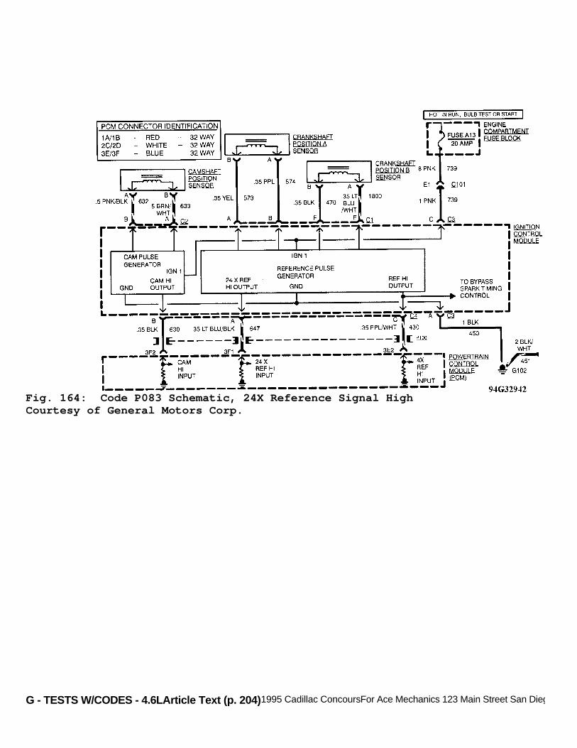
G - TESTS W/CODES - 4.6LArticle Text (p. 204)1995 Cadillac ConcoursFor Ace Mechanics 123 Main Street San Diego Ca 92126
Fig. 164: Code P083 Schematic, 24X Reference Signal HighCourtesy of General Motors Corp.

G - TESTS W/CODES - 4.6LArticle Text (p. 205)1995 Cadillac ConcoursFor Ace Mechanics 123 Main Street San Diego Ca 92126
Fig. 165: Code P083 Diag. Flow Chart - 1 Of 2, 24X Reference SignalHighCourtesy of General Motors Corp.

G - TESTS W/CODES - 4.6LArticle Text (p. 206)1995 Cadillac ConcoursFor Ace Mechanics 123 Main Street San Diego Ca 92126Fig. 166: Code P083 Diag. Flow Chart - 2 Of 2, 24X Reference SignalHighCourtesy of General Motors Corp.
CODE P085, IDLE THROTTLE ANGLE TOO HIGH
G - TESTS W/CODES - 4.6LArticle Text (p. 207)1995 Cadillac Concours
PCM continuously learns base idle position. This base idleposition is the relationship of engine RPM to throttle position. PCMis limited to a fixed amount of learned throttle angle that it canapply. When this limit is reached, Code P085 will set. The cause ofthis increase in learned throttle angle is usually deposits inthrottle body.
Test Conditions Constantly monitored.
Failure Conditions A/C on or off, learned idle throttle angle 3.9 degrees orgreater.
Action PCM turns on MIL.
NOTE: Test number refers to number on diagnostic chart.
1) Checks for other throttle position sensor codes being set,causing other throttle body problems. 2) Checks if throttle body deposits are causing the increasein learned throttle angle. Check for loose fitting air duct or aircleaner causing debris to enter throttle body. 3) Checks if ISC motor can retract far enough to closethrottle position switch. 4) Checks for proper operation of ISC motor.
Notes On Intermittents PCM Code P085 may set due to an engine overheated conditionin which PCM will only allow engine to run on 4 cylinders, causing ahigh idle throttle angle. If this occurs, clear PCM Code P085, resetidle learn using PCM override PS13 and perform TP sensor/idle learn.

G - TESTS W/CODES - 4.6LArticle Text (p. 208)1995 Cadillac ConcoursFor Ace Mechanics 123 Main Street San Diego Ca 92126
Fig. 167: Code P085 Schematic, Idle Throttle Angle Too HighCourtesy of General Motors Corp.

G - TESTS W/CODES - 4.6LArticle Text (p. 209)1995 Cadillac ConcoursFor Ace Mechanics 123 Main Street San Diego Ca 92126
Fig. 168: Code P085 Diagnostic Flow Chart, Idle Throttle Angle TooHighCourtesy of General Motors Corp.
CODE P086, UNDEFINED GEAR RATIO
Transaxle gear ratio is calculated from ratio of turbinespeed against output speed. This test checks gear ratio which is notpossible to obtain under normal operating condition of transaxle, ifsuch gear ratio is observed, Code P086 is set.
Test Conditions Codes P021, P022, P024, P056 and P075 not set. Enginerunning and vehicle speed at 7 MPH or greater. Throttle position at 11

G - TESTS W/CODES - 4.6L
degrees or greater. Transaxle not in Park or Neutral and commandedtransaxle line pressure 100 psi or greater.
Failure Conditions: * Gear ratio less than 2.87 or greater than 3.11 for 3 seconds. * Gear ratio less than 1.54 or greater than 1.71 for 3 seconds. * Gear ratio less than 0.95 or greater than 1.05 for 3 seconds. * Gear ratio less than 0.65 or greater than 0.71 for 3 seconds. * Gear ratio less than 2.07 or greater than 2.23 for 3 seconds.
Action PCM turns on MIL. PCM de-energizes transaxle pressure controlsolenoid and torque management is disabled. Maintains transaxle shiftadapts at current levels.
NOTE: Test numbers refer to numbers on diagnostic chart.
1) Install pressure gauges to transaxle. 2) Comparing gear box ratio (PD76) and transaxle pressureswitch input (PD71) will determine what gear PCM was commanding andwhat possible gear ratio change resulted from such command.
Fig. 169: Code P086 Schematic, Undefined Gear RatioCourtesy of General Motors Corp.

G - TESTS W/CODES - 4.6LArticle Text (p. 211)1995 Cadillac ConcoursFor Ace Mechanics 123 Main Street San Diego Ca 92126
Fig. 170: Code P086 Diagnostic Flow Chart - 1 Of 2, Undefined GearRatioCourtesy of General Motors Corp.

G - TESTS W/CODES - 4.6LArticle Text (p. 212)1995 Cadillac ConcoursFor Ace Mechanics 123 Main Street San Diego Ca 92126
Fig. 171: Code P086 Diagnostic Flow Chart - 2 Of 2, Undefined GearRatioCourtesy of General Motors Corp.

G - TESTS W/CODES - 4.6LArticle Text (p. 213)1995 Cadillac Concours
CODE P088, TCC NOT DISENGAGING
This test checks for TCC slippage. If slippage is not presentwhen transaxle is operating at a given condition, TCC is engaged.
Test Conditions Codes P021, P022, P028 and P056 not set. Engine running andthrottle position at 15.7 degrees or greater. Transaxle in 3rd or 4thgear.
Failure Condition Slip speed at less than 5 or equals to 10 RPM for 4 seconds(slip = engine RPM - transaxle RPM).
Action PCM turn on MIL and freezes shift adapts from being updated.TCC disabled.
Action PCM turn on MIL.
NOTE: Test numbers refer to numbers on diagnostic chart.
1) Checks circuit No. 422 (Tan/Black wire) between engineharness connector C129 and PCM connector 3E13 for short to ground. 2) Isolates short to ground between engine harness or PCM. 3) Checks circuit No. 422 for short to ground insidetransaxle.

G - TESTS W/CODES - 4.6LArticle Text (p. 214)1995 Cadillac ConcoursFor Ace Mechanics 123 Main Street San Diego Ca 92126Fig. 172: Code P088 Schematic, TCC Not DisengagingCourtesy of General Motors Corp.
Fig. 173: Code P088 Diagnostic Flow Chart, TCC Not DisengagingCourtesy of General Motors Corp.

G - TESTS W/CODES - 4.6LArticle Text (p. 215)1995 Cadillac ConcoursFor Ace Mechanics 123 Main Street San Diego Ca 92126
CODE P089, LONG SHIFT AND MAXIMUM ADAPT
Transaxle pressure is modified by an adaptive modifier usedto control gear shift execution time. This test checks the shiftextension and time it takes to accomplish it. If it takes longer than.55 second and adaptive modifier cannot shorten this time, counterwill increment. When counter reaches 5, Code P089 will set.
Test Conditions Codes P021, P022, P024, P056, P057, P059 and P075 not set.Vehicle speed at 10 MPH or greater and throttle position is at 15.7degrees or greater. Transaxle temperature at 194øF (90øC) or greater.
Failure Conditions: * 1-2 shift time 5.5 seconds or greater and adapt cannot shorten shift time for 5 shifts. * 2-3 shift time 5.5 seconds or greater and adapt cannot shorten shift time for 5 shifts. * 3-4 shift time 5.5 seconds or greater and adapt cannot shorten shift time for 5 shifts.
Action PCM turns on MIL and de-energizes transaxle pressure controlsolenoid.
NOTE: Test numbers refer to numbers on diagnostic chart.
1) Install transaxle pressure gauge. 2) Using operator information to diagnose which shift causedthe code to set. 3) Code P089 snapshot information can be used to determinewhich shift the long time occurred on.
Notes On Intermittents Due to complexity of the 4T80-E transaxle, an intermittentPCM Code P089 will be very difficult to diagnose. Hold off maintenanceuntil specific problem is identified.

G - TESTS W/CODES - 4.6LArticle Text (p. 216)1995 Cadillac ConcoursFor Ace Mechanics 123 Main Street San Diego Ca 92126
Fig. 174: Code P089 Schematic, Long Shift And Maximum AdaptCourtesy of General Motors Corp.

G - TESTS W/CODES - 4.6LArticle Text (p. 217)1995 Cadillac ConcoursFor Ace Mechanics 123 Main Street San Diego Ca 92126
Fig. 175: Code P089 Diagnostic Flow Chart - 1 Of 2, Long Shift AndMaximum AdaptCourtesy of General Motors Corp.
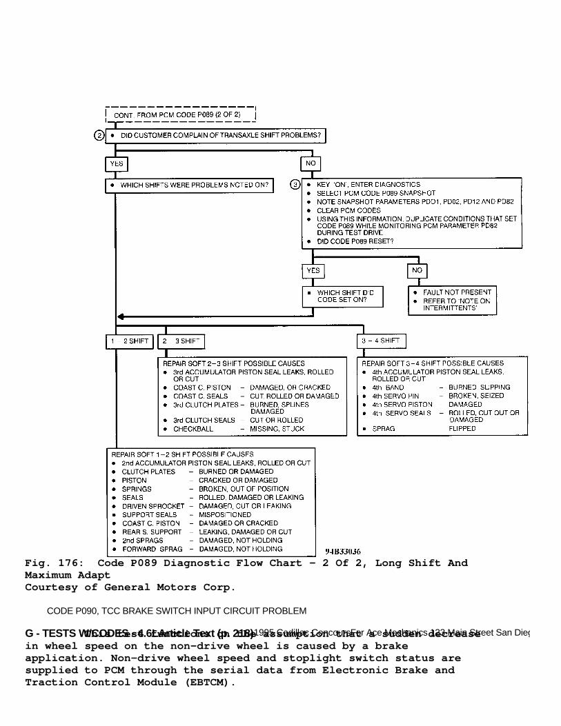
G - TESTS W/CODES - 4.6LArticle Text (p. 218)1995 Cadillac ConcoursFor Ace Mechanics 123 Main Street San Diego Ca 92126
Fig. 176: Code P089 Diagnostic Flow Chart - 2 Of 2, Long Shift AndMaximum AdaptCourtesy of General Motors Corp.
CODE P090, TCC BRAKE SWITCH INPUT CIRCUIT PROBLEM
This test functions on the assumption that a sudden decreasein wheel speed on the non-drive wheel is caused by a brakeapplication. Non-drive wheel speed and stoplight switch status aresupplied to PCM through the serial data from Electronic Brake andTraction Control Module (EBTCM).
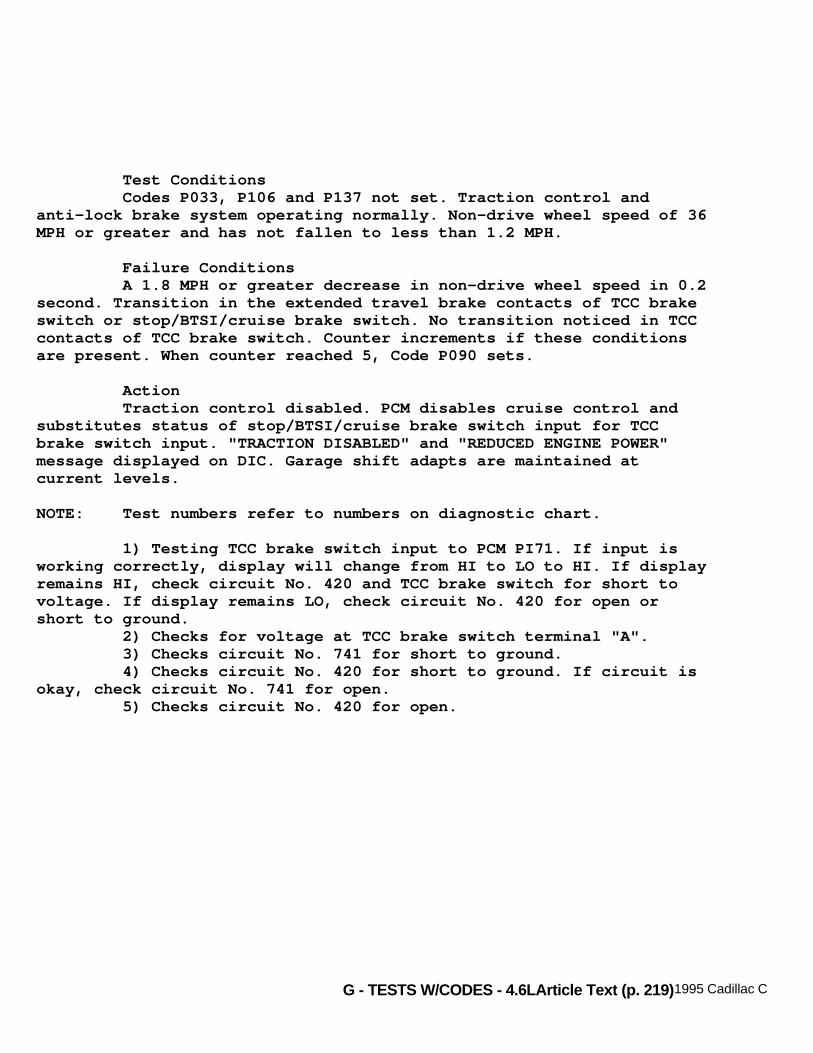
G - TESTS W/CODES - 4.6LArticle Text (p. 219)1995 Cadillac Concours
Test Conditions Codes P033, P106 and P137 not set. Traction control andanti-lock brake system operating normally. Non-drive wheel speed of 36MPH or greater and has not fallen to less than 1.2 MPH.
Failure Conditions A 1.8 MPH or greater decrease in non-drive wheel speed in 0.2second. Transition in the extended travel brake contacts of TCC brakeswitch or stop/BTSI/cruise brake switch. No transition noticed in TCCcontacts of TCC brake switch. Counter increments if these conditionsare present. When counter reached 5, Code P090 sets.
Action Traction control disabled. PCM disables cruise control andsubstitutes status of stop/BTSI/cruise brake switch input for TCCbrake switch input. "TRACTION DISABLED" and "REDUCED ENGINE POWER"message displayed on DIC. Garage shift adapts are maintained atcurrent levels.
NOTE: Test numbers refer to numbers on diagnostic chart.
1) Testing TCC brake switch input to PCM PI71. If input isworking correctly, display will change from HI to LO to HI. If displayremains HI, check circuit No. 420 and TCC brake switch for short tovoltage. If display remains LO, check circuit No. 420 for open orshort to ground. 2) Checks for voltage at TCC brake switch terminal "A". 3) Checks circuit No. 741 for short to ground. 4) Checks circuit No. 420 for short to ground. If circuit isokay, check circuit No. 741 for open. 5) Checks circuit No. 420 for open.
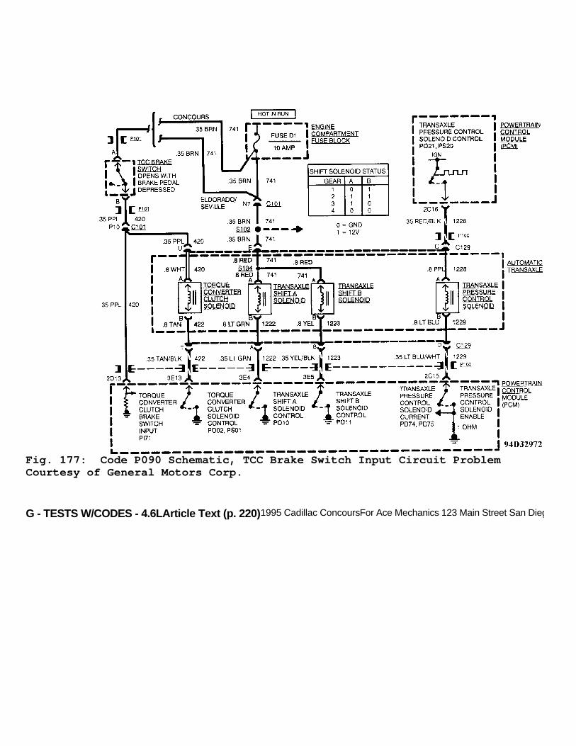
G - TESTS W/CODES - 4.6LArticle Text (p. 220)1995 Cadillac ConcoursFor Ace Mechanics 123 Main Street San Diego Ca 92126
Fig. 177: Code P090 Schematic, TCC Brake Switch Input Circuit ProblemCourtesy of General Motors Corp.
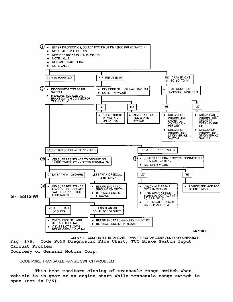
G - TESTS W/CODES - 4.6LArticle Text (p. 221)1995 Cadillac ConcoursFor Ace Mechanics 123 Main Street San Diego Ca 92126
Fig. 178: Code P090 Diagnostic Flow Chart, TCC Brake Switch InputCircuit ProblemCourtesy of General Motors Corp.
CODE P091, TRANSAXLE RANGE SWITCH PROBLEM
This test monitors closing of transaxle range switch whenvehicle is in gear or an engine start while transaxle range switch isopen (not in P/N).

G - TESTS W/CODES - 4.6LArticle Text (p. 222)1995 Cadillac ConcoursFor Ace Mechanics 123 Main Street San Diego Ca 92126
Test Condition 1 Vehicle not moving.
Test Condition 2 Gear ratio indicating P/N range.
Failure Conditions 1 Engine speed changes from zero to higher RPM without P/Ninput to PCM HI (not in P/N). At least 5 seconds have elapsed sincetransaxle switch was moved.
Failure Conditions 2 Codes P024, P075 and P086 not set. P/N input to PCM LO (inP/N). Engine running and throttle position 15.7 degrees or greater.Vehicle speed at 7 MPH or greater. Gear ratio of 3.11 or less (vehiclein gear). All these conditions happened within 5 seconds.
Actions PCM turns on SERVICE VEHICLE SOON light. PCM disables cruisecontrol and will substitute gear status from transaxle pressure switchfor transaxle range switch.
NOTE: Test numbers refer to numbers on diagnostic chart.
1) Checks PCM status light. AUTO should be displayed whengearshift is in Park or Neutral and OFF should be displayed ifgearshift is in any other gear. 2) Checks transaxle range switch for open. 3) Checks circuit No. 451 for open. 4) Checks circuit No. 434 for open. 5) Checks if fault is still present. 6) Checks for shorted transaxle range switch. 7) Checks circuit No. 434 for short to ground.
Note On Intermittents Check for intermittent short to ground in circuit No. 434. Astall or a near stall condition which may set Code P054 or P095 andmay cause a false Code P091 to set due to engine transition fromrunning to not running (or near stall) then back to running withouttransaxle switch being in Park or Neutral.

G - TESTS W/CODES - 4.6LArticle Text (p. 223)1995 Cadillac ConcoursFor Ace Mechanics 123 Main Street San Diego Ca 92126
Fig. 179: Code P091 Schematic, Transaxle Range Switch ProblemCourtesy of General Motors Corp.

G - TESTS W/CODES - 4.6LArticle Text (p. 224)1995 Cadillac ConcoursFor Ace Mechanics 123 Main Street San Diego Ca 92126
Fig. 180: Code P091 Diagnostic Flow Chart, Transaxle Range Sw.ProblemCourtesy of General Motors Corp.
CODE P092, HEATED WINDSHIELD REQUEST PROBLEM
This test will detect a problem with heated windshield fastidle request circuit to PCM. When circuit is grounded by heatedwindshield module, PCM will increase idle speed to compensate forextra load placed on alternator. Code P092 will set when signal is lowfor more than 10 minutes.
Test Conditions Engine running.
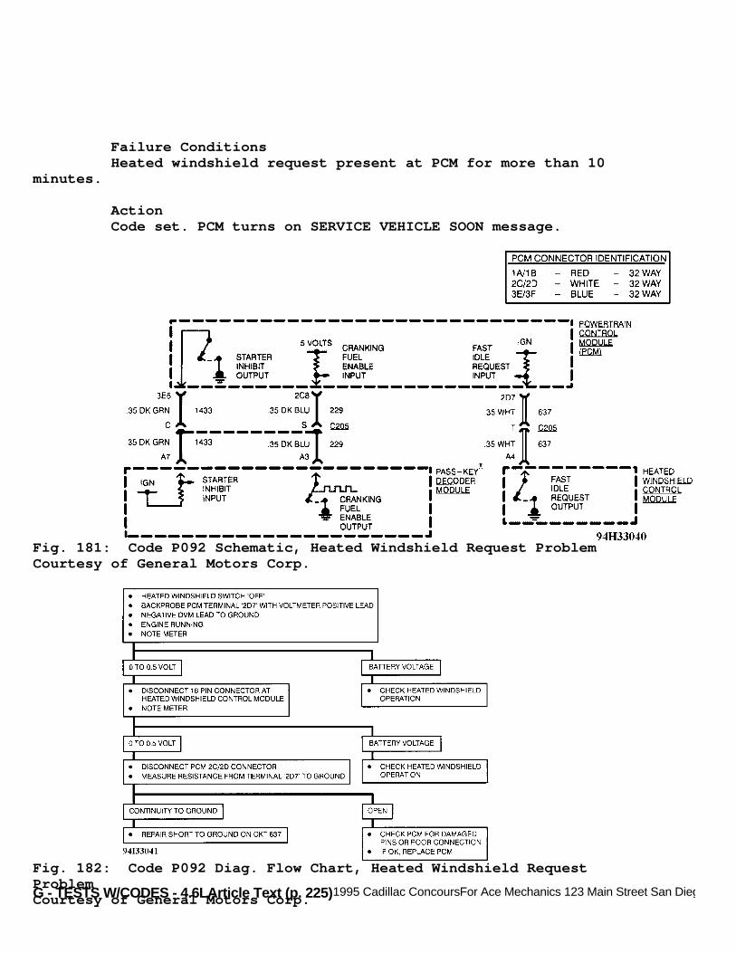
G - TESTS W/CODES - 4.6LArticle Text (p. 225)1995 Cadillac ConcoursFor Ace Mechanics 123 Main Street San Diego Ca 92126
Failure Conditions Heated windshield request present at PCM for more than 10minutes.
Action Code set. PCM turns on SERVICE VEHICLE SOON message.
Fig. 181: Code P092 Schematic, Heated Windshield Request ProblemCourtesy of General Motors Corp.
Fig. 182: Code P092 Diag. Flow Chart, Heated Windshield RequestProblemCourtesy of General Motors Corp.

G - TESTS W/CODES - 4.6LArticle Text (p. 226)1995 Cadillac Concours
CODE P093, TRACTION CONTROL SYSTEM PWM LINK FAILURE
This test checks for traction control system PWM link failureto PCM.
Test Conditions Code P137 not set. Traction control not failed.
Failure Conditions No rising edges of traction control system PWM signals arereceived for 3 seconds.
Action TRACTION DISABLED message displayed in DIC. PCM disables 1stgear and transaxle shift adapts are maintained at current levels.
NOTE: Test numbers refer to numbers on diagnostic chart.
1) Checks for traction control communication code that wasset. Determines if it is a PCM problem or not. 2) Checks for proper output voltage from PCM. 3) Checks circuit No. 594 for open. 4) Checks circuit No. 594 for short to ground. 5) Checks circuit No. 594 for short to voltage. 6) Checks for intermittent traction control problem. Iftraction control system is okay, check for faulty PCM or EBTCM.
Fig. 183: Code P093 Schematic, Traction Control System PWM LinkFailureCourtesy of General Motors Corp.

G - TESTS W/CODES - 4.6LArticle Text (p. 227)1995 Cadillac Concours
Fig. 184: Code P093 Diagnostic Flow Chart, Traction Control SystemPWM Link FailureCourtesy of General Motors Corp.
CODE P094, TRANSAXLE SHIFT SOLENOID "A" PROBLEM

G - TESTS W/CODES - 4.6LArticle Text (p. 228)1995 Cadillac ConcoursFor Ace Mechanics 123 Main Street San Diego Ca 92126
Monitors commanded gear versus transaxle gear ratio to checktransaxle shift solenoid "A". If gear ratio falls out of range for agiven gear, Code P094 will set.
Test Conditions Codes P021, P022, P024, P028 and P056 not set. Transaxlepressure switch indicating transaxle in D1, D2, D3 or D4 position.Engine running and vehicle speed at 7 MPH or greater. Throttleposition at 11 degrees or greater.
Failure Conditions:
* Gear ratio between 1.54-1.71 for 5 seconds, 1st gear commanded. * Gear ratio between 2.87-3.11 for 5 seconds, 2nd gear commanded. * Gear ratio between 0.67-0.71 for 5 seconds, 3rd gear commanded. * Gear ratio between 0.95-1.05 for 5 seconds, 4th gear commanded.
Action PCM turns on MIL. PCM allows only 2nd gear when forward gearis selected.
NOTE: Test numbers refer to numbers on diagnostic chart.
1) Checks if Code P117 is set. Presence of code will causetransaxle problem. 2) Checks if shift solenoid "A" is HI when it be LO or vice-versa. 3) Checks if PCM is operating correctly and setting a falsecode. 4) Checks if circuit No. 741 is open at connector. 5) Checks if circuit No. 1222 (engine harness side) is open. 6) Checks if circuit No. 1222 (trans. harness side) isshorted to ground inside transaxle. 7) Checks for an open circuit inside transaxle. 8) Checks if circuit No. 1222 (trans. harness side) for shortto voltage inside transaxle. 9) Checks if circuit No. 1222 (engine harness side) for shortto voltage from connector to PCM. 10) Checks for possible cause for getting 4th gear when 3rdgear is commanded. 11) Checks for possible cause for getting 3rd gear when 4thgear is commanded. 12) Checks for possible cause for getting 2nd gear when 1stgear is commanded.

G - TESTS W/CODES - 4.6LArticle Text (p. 229)1995 Cadillac ConcoursFor Ace Mechanics 123 Main Street San Diego Ca 92126
13) Checks for possible cause for getting 1st gear when 2ndgear is commanded.
Fig. 185: Code P094 Schematic, Transaxle Shift Solenoid "A" ProblemCourtesy of General Motors Corp.
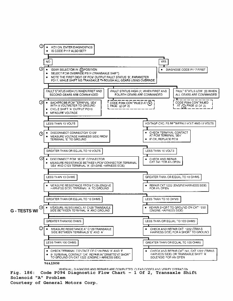
G - TESTS W/CODES - 4.6LArticle Text (p. 230)1995 Cadillac ConcoursFor Ace Mechanics 123 Main Street San Diego Ca 92126
Fig. 186: Code P094 Diagnostic Flow Chart - 1 Of 2, Transaxle ShiftSolenoid "A" ProblemCourtesy of General Motors Corp.

G - TESTS W/CODES - 4.6LArticle Text (p. 231)1995 Cadillac Concours
Fig. 187: Code P094 Diagnostic Flow Chart - 2 Of 2, Transaxle ShiftSolenoid "A" ProblemCourtesy of General Motors Corp.
CODE P095, ENGINE STALL OR NEAR STALL DETECTED
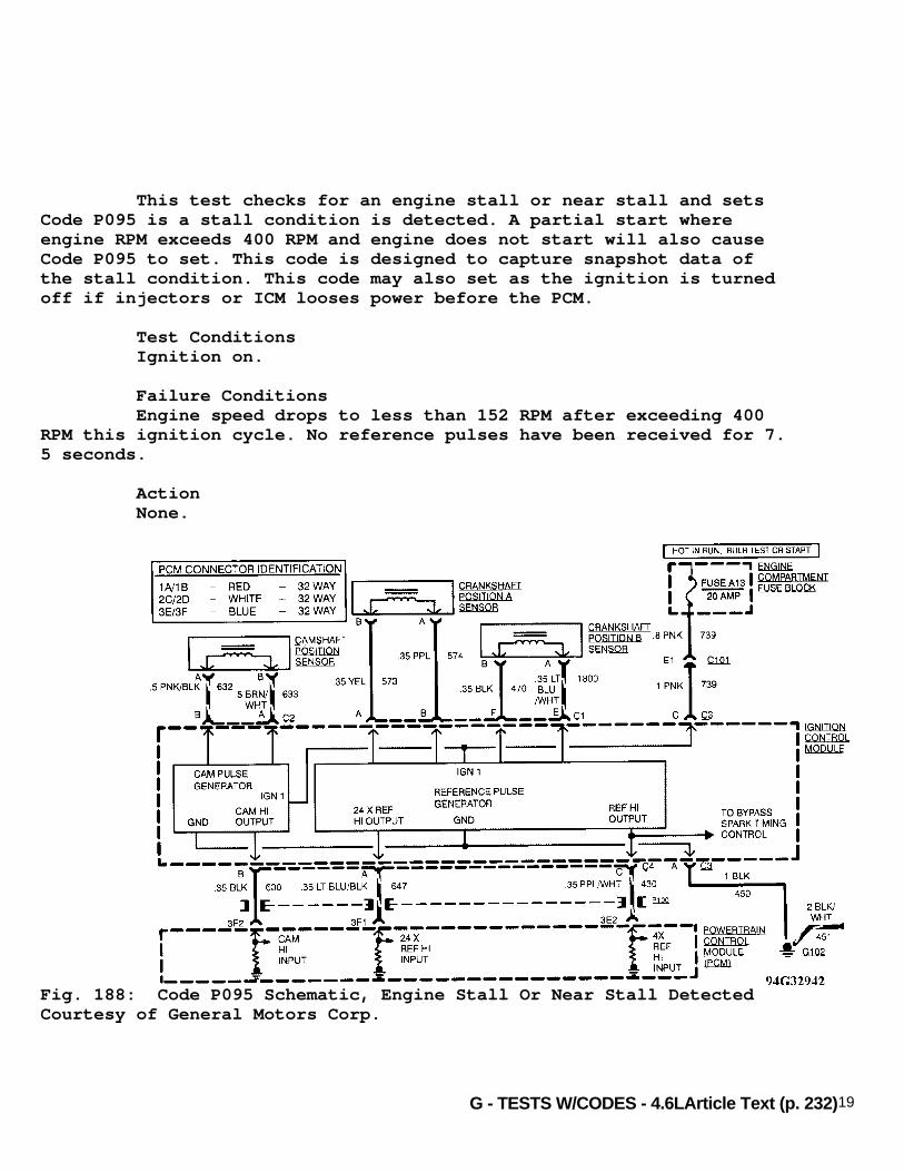
G - TESTS W/CODES - 4.6LArticle Text (p. 232)1995 Cadillac Concours
This test checks for an engine stall or near stall and setsCode P095 is a stall condition is detected. A partial start whereengine RPM exceeds 400 RPM and engine does not start will also causeCode P095 to set. This code is designed to capture snapshot data ofthe stall condition. This code may also set as the ignition is turnedoff if injectors or ICM looses power before the PCM.
Test Conditions Ignition on.
Failure Conditions Engine speed drops to less than 152 RPM after exceeding 400RPM this ignition cycle. No reference pulses have been received for 7.5 seconds.
Action None.
Fig. 188: Code P095 Schematic, Engine Stall Or Near Stall DetectedCourtesy of General Motors Corp.

G - TESTS W/CODES - 4.6LArticle Text (p. 233)1995 Cadillac ConcoursFor Ace Mechanics 123 Main Street San Diego Ca 92126
Fig. 189: Code P095 Diagnostic Flow Chart, Engine Stall Or Near StallDetectedCourtesy of General Motors Corp.
CODE P096, TORQUE CONVERTER OVER STRESS
Primary purpose of Code P096 is to detect an action of driverwhich could cause an unsafe condition or damage to vehicle. Code P096can be driver-induced by application of brake and accelerator at sametime.

G - TESTS W/CODES - 4.6LArticle Text (p. 234)1995 Cadillac ConcoursFor Ace Mechanics 123 Main Street San Diego Ca 92126
Test Conditions Codes P021, P022 and P024 not set.
Failure Conditions Brake applied, transaxle in Drive or Reverse, vehicle speed 5MPH or less and throttle angle greater than 65 degrees for 12 seconds.
Action Code P096 is set. PCM turns on MIL.
Fig. 190: Code P096 Schematic, Torque Converter Over StressCourtesy of General Motors Corp.
CODE P097, PARK/NEUTRAL-TO-DRIVE/REVERSE SHIFT AT HIGH THROTTLE ANGLE
Primary purpose of Code P097 is to detect an action ofvehicle operator which could cause an unsafe condition or damage tovehicle. When such conditions exists, Code P097 is set and enginepower will be reduced by disabling fuel injector to individualcylinders.
Test Conditions Codes P021 and P022 not set.

G - TESTS W/CODES - 4.6LArticle Text (p. 235)1995 Cadillac ConcoursFor Ace Mechanics 123 Main Street San Diego Ca 92126
Failure Conditions Engine speed greater than 2000 RPM, gear selector moved fromPark or Neutral to Drive or Reverse, vehicle speed less than 6 MPH andthrottle angle is 20 degrees or greater.
Action "REDUCED ENGINE POWER" message displayed on DIC. PCM willdisable selected injectors to reduce engine power and set Code P097.
Fig. 191: Code P097 Schematic, Park/Neutral-To-Drive/Reverse Shift AtHigh Throttle AngleCourtesy of General Motors Corp.
CODE P099, CRUISE SERVO APPLIED NOT IN CRUISE
This diagnostic test monitors cruise control servo positionsensor to ensure servo has released throttle after cruise control hasbeen disengaged for 2 seconds. If cruise control servo has not beenreleased, Code P099 will set and engine power will be reduced bydisabling fuel to individual cylinders. Code P068 may disable cruisecontrol and lead to setting Code PCM P099.

G - TESTS W/CODES - 4.6LArticle Text (p. 236)1995 Cadillac ConcoursFor Ace Mechanics 123 Main Street San Diego Ca 92126
Test Conditions Engine running. Code PS07 override not active.
Failure Conditions Failure conditions for PCM code set change depending onwhether code was previously set or not.
Code P099 not previously set:
* Cruise control disengaged for 2 seconds. * Throttle angle greater than 20 degrees, TP sensor not failed. * MAP greater than 70 kPa, TP sensor failed. * Cruise control servo stroke greater than 63 percent for 0.1 second.
Code P099 previously set:
* Cruise control disengaged for 2 seconds. * Throttle angle greater than 16 degrees, TP sensor not failed. * MAP greater than 55 kPa, TP sensor failed. * Cruise control servo stroke greater than 37 percent for 0.1 second.
Action REDUCED ENGINE POWER displayed on DIC. PCM disables cruisecontrol and reduces fuel delivery to selected cylinders.
NOTE: Test numbers refer to numbers on diagnostic chart.
1) Checks if PCM can control cruise control solenoid. 2) Checks if cruise control position sensor is workingcorrectly. 3) Checks if cruise control servo will extend fully. If servodoes not extend fully, check circuit No. 402 for a short to voltage.
Note On Intermittent Code P099 may be inadvertently induced by technician usingcruise servo to bump up throttle.
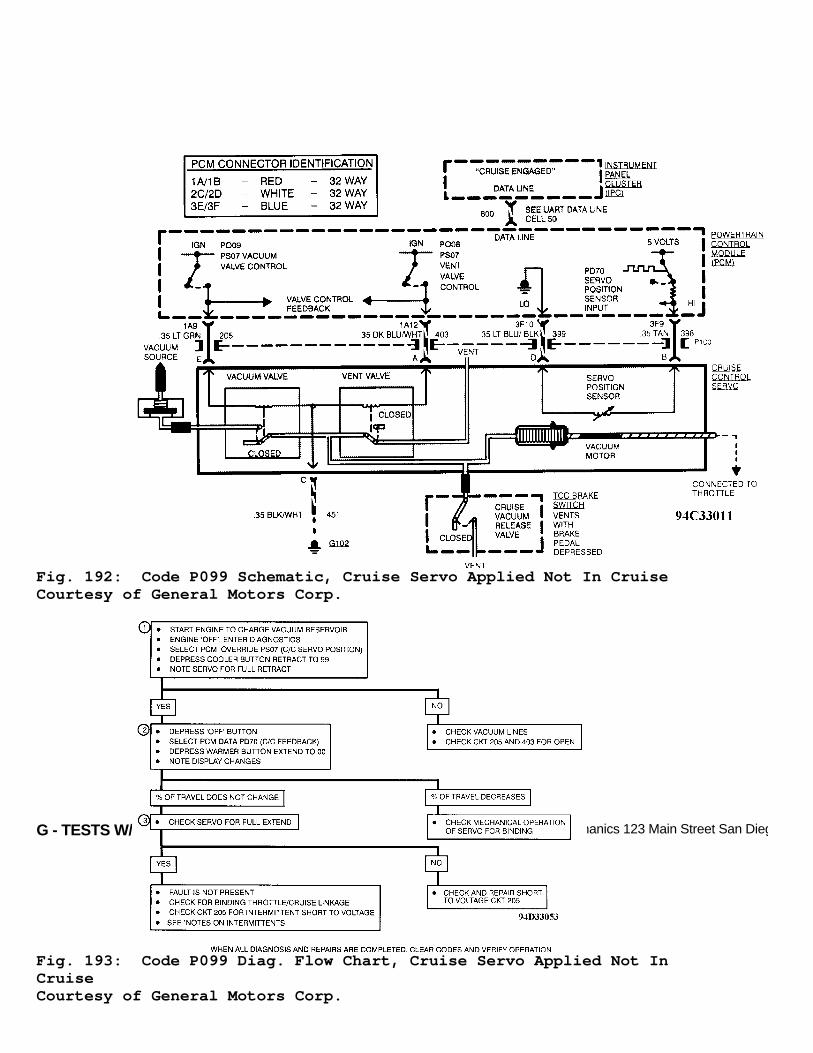
G - TESTS W/CODES - 4.6LArticle Text (p. 237)1995 Cadillac ConcoursFor Ace Mechanics 123 Main Street San Diego Ca 92126
Fig. 192: Code P099 Schematic, Cruise Servo Applied Not In CruiseCourtesy of General Motors Corp.
Fig. 193: Code P099 Diag. Flow Chart, Cruise Servo Applied Not InCruiseCourtesy of General Motors Corp.

G - TESTS W/CODES - 4.6LArticle Text (p. 238)1995 Cadillac Concours
CODE P102, SHORTED BRAKE BOOSTER VACUUM (BBV) SENSOR
Brake booster vacuum sensor changes resistance based onvacuum inside brake booster. This test checks for a vacuum readingwhich can be caused by a shorted sensor or a short on circuit No. 1726or and open on circuit No. 808. Every time TCC brake switch cyclesfrom closed to open with engine not at idle, this test checks for ashorted vacuum signal. If shorted vacuum signal is detected for 5consecutive cycle of TCC brake switch, Code P102 will set. Any cycleof TCC brake switch where a shorted vacuum signal is not detected willreset counter to zero.
Test Conditions Codes P031, P032, P034, P071 and P090 not set. One secondhas passed since TCC brake switch was cycled from closed to open. MAPvalue at 30 kPa or greater (engine not at idle) for one second.Failure counter will increment when all these conditions are presentand brake booster vacuum signal is 82 kPa or greater. Failure counterwill reset when all these conditions are present but vacuum signal isless than 82 kPa.
Failure Conditions Failure counter at 7 counts or greater.
Action PCM turns on SERVICE VEHICLE SOON message.
NOTE: Test numbers refer to numbers on diagnostic chart.
1) PCM data PD84 will read 82-84 kPa with sensor shorted. Ifreading is not as specified, fault is not present. 2) If PCM data PD84 reads -11 to -8 kPa with sensorunplugged, check circuit No. 476 for open or for a shorted sensor. 3) Checks circuit No. 1726 for short to voltage.
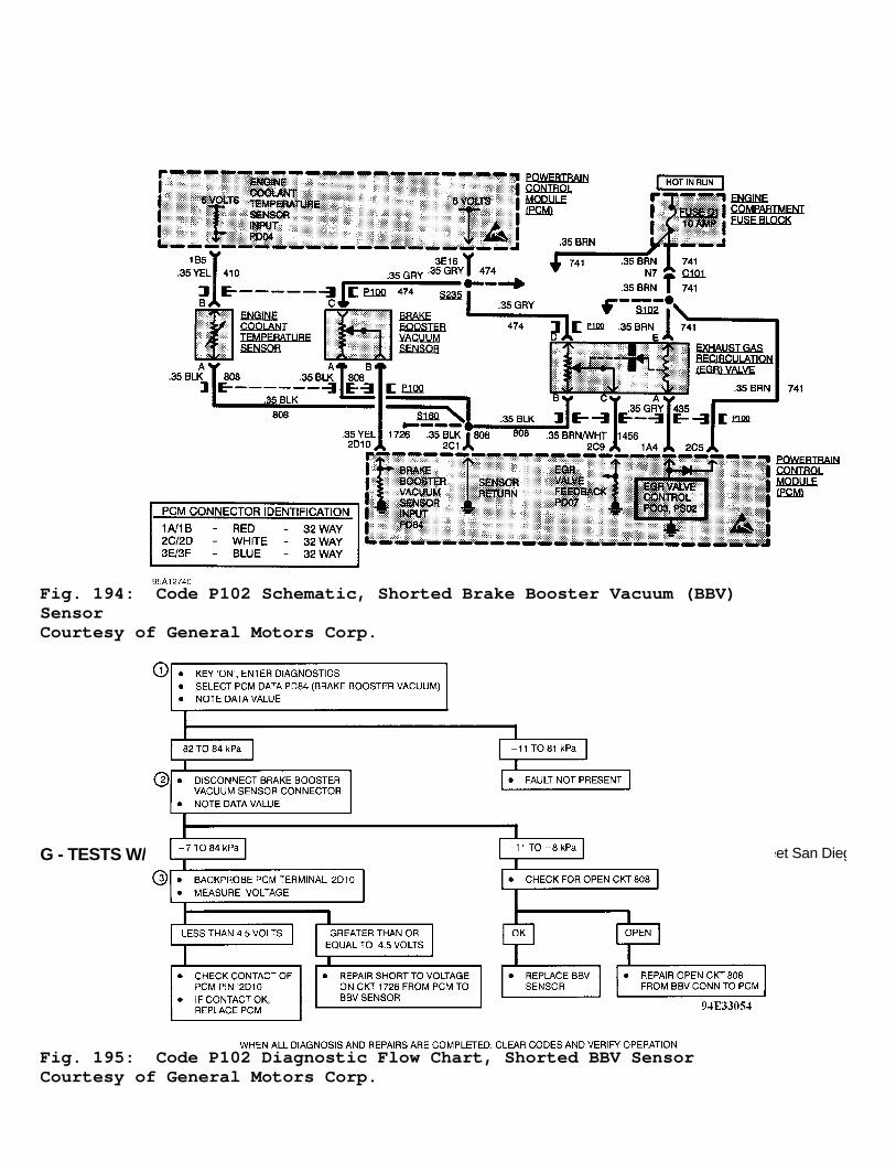
G - TESTS W/CODES - 4.6LArticle Text (p. 239)1995 Cadillac ConcoursFor Ace Mechanics 123 Main Street San Diego Ca 92126
Fig. 194: Code P102 Schematic, Shorted Brake Booster Vacuum (BBV)SensorCourtesy of General Motors Corp.
Fig. 195: Code P102 Diagnostic Flow Chart, Shorted BBV SensorCourtesy of General Motors Corp.

G - TESTS W/CODES - 4.6LArticle Text (p. 240)1995 Cadillac ConcoursFor Ace Mechanics 123 Main Street San Diego Ca 92126
CODE P103, OPEN BRAKE BOOSTER VACUUM (BBV) SENSOR
Brake booster vacuum sensor changes resistance based onvacuum inside brake booster. This test checks for a vacuum readingwhich can be caused by an open sensor or open on circuit No. 474 orand short to ground on circuit No. 1726. When PCM detects as brakebooster vacuum signal that is too low, Code P103 will set.
Test Conditions Tested continuously.
Failure Conditions Failure counter at 7 counts or greater.
Action PCM turns on SERVICE VEHICLE SOON message.
NOTE: Test numbers refer to numbers on diagnostic chart.
1) If brake booster vacuum sensor is open PD84 should read -8kPa or less. 2) If brake booster vacuum sensor is open, PD84 should read82-84 kPa with sensor terminals jumpered together. 3) Checks circuit No. 1726 for short to ground between BBVand PCM. 4) Checks circuit No. 1726 for open between BBV and PCM.
Fig. 196: Code P103 Schematic, Open Brake Booster Vacuum (BBV) SensorCourtesy of General Motors Corp.

G - TESTS W/CODES - 4.6LArticle Text (p. 241)1995 Cadillac ConcoursFor Ace Mechanics 123 Main Street San Diego Ca 92126
Fig. 197: Code P103 Diagnostic Flow Chart, Open BBV SensorCourtesy of General Motors Corp.
CODE P105, BRAKE BOOSTER VACUUM (BBV) SENSOR TOO LOW
Brake booster vacuum sensor changes resistance based onvacuum inside brake booster. This test monitors brake booster vacuumalong with manifold vacuum. If brake booster vacuum is too low for agiven manifold vacuum and brakes are not applied, then brake boostervacuum signal must be in error and will set Code P105.
Test Conditions Codes P031, P032, P034, P071, P103 and P137 not set. Enginespeed at 500 RPM or greater for 20 seconds and brake not applied.Barometric pressure at 72 kPa or greater and MAP at 60 kPa or less.
Failure Conditions Brake booster vacuum 5 kPa or less for 16 seconds.
Action
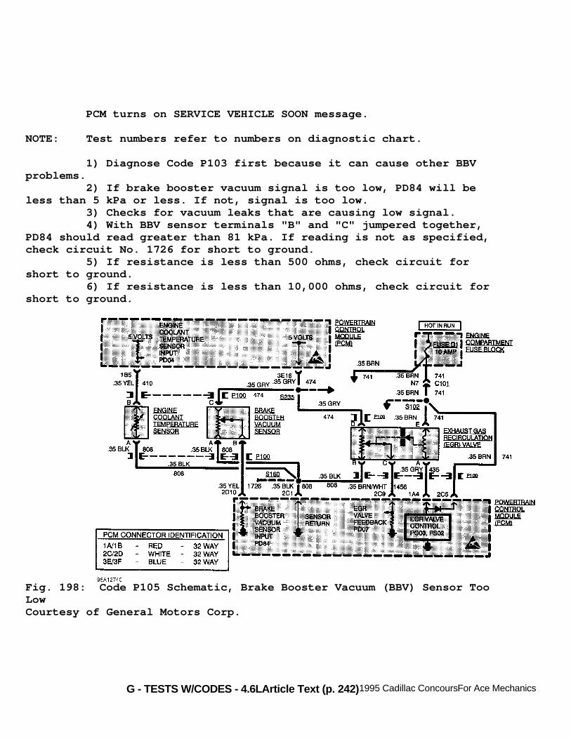
G - TESTS W/CODES - 4.6LArticle Text (p. 242)1995 Cadillac ConcoursFor Ace Mechanics 123 Main Street San Diego Ca 92126
PCM turns on SERVICE VEHICLE SOON message.
NOTE: Test numbers refer to numbers on diagnostic chart.
1) Diagnose Code P103 first because it can cause other BBVproblems. 2) If brake booster vacuum signal is too low, PD84 will beless than 5 kPa or less. If not, signal is too low. 3) Checks for vacuum leaks that are causing low signal. 4) With BBV sensor terminals "B" and "C" jumpered together,PD84 should read greater than 81 kPa. If reading is not as specified,check circuit No. 1726 for short to ground. 5) If resistance is less than 500 ohms, check circuit forshort to ground. 6) If resistance is less than 10,000 ohms, check circuit forshort to ground.
Fig. 198: Code P105 Schematic, Brake Booster Vacuum (BBV) Sensor TooLowCourtesy of General Motors Corp.

G - TESTS W/CODES - 4.6LArticle Text (p. 243)1995 Cadillac ConcoursFor Ace Mechanics 123 Main Street San Diego Ca 92126Fig. 199: Code P105 Diagnostic Flow Chart, BBV Sensor Too LowCourtesy of General Motors Corp.
CODE P106, STOPLIGHT SWITCH INPUT CIRCUIT PROBLEM
This test functions on the assumption that a sudden decreasein wheel speed on the non-drive wheel is caused by a brake

G - TESTS W/CODES - 4.6L
application. Non-drive wheel speed and stoplight switch status aresupplied to PCM through the serial data from Electronic Brake andTraction Control Module (EBTCM).
Test Conditions Codes P033, P090 and P137 not set. Traction control and ABSare operating normally and non-drive wheel speed at 36 MPH or greater.
Failure Conditions A 1.8 MPH or greater decrease in non-drive wheel speed in 0.2second. Transition in TCC or extended travel contacts of TCC brakeswitch or no transition of stop/BTSI/cruise brake switch noticed. Ifthese conditions are met, trouble code will set.
Action Traction control disabled. PCM will set stop/BTSI/cruisebrake switch status not applied. TRACTION DISABLED and REDUCED ENGINEPOWER message displayed.
NOTE: Test numbers refer to numbers on diagnostic chart.
1) Checks if PCM input test PI89 will cycle when brake pedalis depressed and released. If PI89 remains HI, check fro short tovoltage in system. If P189 remains LO, check for open or short toground in system. 2) Checks for voltage supplied to brake switch. 3) Checks circuit No. 540 for short to ground. 4) Checks circuit No. 20 for short to ground. 5) Checks circuit No. 20 for open or for faulty PCM.
Fig. 200: Code P106 Schematic, Stoplight Switch Input Circuit ProblemCourtesy of General Motors Corp.

G - TESTS W/CODES - 4.6LArticle Text (p. 245)1995 Cadillac Concours
Fig. 201: Code P106 Diagnostic Flow Chart, Stoplight Switch InputCircuit ProblemCourtesy of General Motors Corp.
CODE P110, ALTERNATOR "L" TERMINAL CIRCUIT PROBLEM
This test monitors alternator feedback and compares it toalternator control in PCM. When PCM commands alternator turned on andfeedback indicates that it is off for 15 seconds, Code P110 will set.PCM initiates alternator operation by supplying 12 volts to alternator

G - TESTS W/CODES - 4.6L
"L" terminal through circuit No. 225. Alternator regulator appliesvoltage to rotor as pulse signal to energize the field windings.Alternator can detect internal faults, setting Code P110. It can alsoself-diagnose a shorted output diode, malfunctioning regulator, openor shorted rotor, over or under voltage condition, shaft not rotatingor open sense lead.
Test Conditions Engine running. PCM commanding alternator on.
Failure Conditions PCM commanding alternator on and alternator feedbackindicating it is off for 15 seconds.
Action BATTERY NO CHARGE message displayed on DIC.
NOTE: Test numbers refer to numbers on diagnostic chart.
1) Checks PCM's ability to cycle alternator control output.If voltage cycles, replace battery. 2) Checks if circuit No. 225 is open or shorted to ground orif PCM is faulty.
Notes On Intermittents A loose or faulty connection at alternator "L" terminal maycause Code P110 to set intermittently.
Fig. 202: Code P110 Schematic, Alternator "L" Terminal CircuitProblemCourtesy of General Motors Corp.

G - TESTS W/CODES - 4.6LArticle Text (p. 247)1995 Cadillac Concours
Fig. 203: Code P110 Diagnostic Flow Chart, Alternator "L" TerminalCircuit ProblemCourtesy of General Motors Corp.
CODE P112, EEPROM FAILURE
Electrically Erasable Programmable Read Only Memory (EEPROM)is used by PCM to store data even when battery power is removed. Itstores TP sensor/idle learned values, transaxle adapt values,transaxle oil life index and cruise control lash/learn. EEPROM storethis information in several locations and if PCM detects a problem inone location of EEPROM, it will store data in another location. If PCMruns out of good locations in the EEPROM to store data, Code P112 willbe stored. PCM stores the same data in its Keep Alive Memory so thateven if EEPROM is bad, Code P112 will set. Vehicle operation willremain unchanged. Even after a code is set, PCM will continue to lookfor good locations in the EEPROM to store data. If a good location isfound, Code P112 will become a history code. If Code P112 is present,PCM must be replaced.
NOTE: Test numbers refer to numbers on diagnostic chart.
1) If Code P112 is set current, PCM cannot find anotherlocation to store data. Replace PCM. 2) Cycle ignition to PCM a chance to find a place to storedata. If trouble code resets, PCM must be replaced.
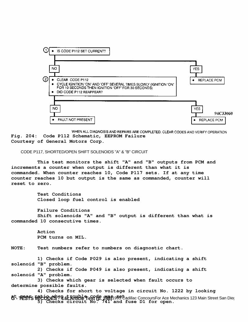
G - TESTS W/CODES - 4.6LArticle Text (p. 248)1995 Cadillac ConcoursFor Ace Mechanics 123 Main Street San Diego Ca 92126
Fig. 204: Code P112 Schematic, EEPROM FailureCourtesy of General Motors Corp.
CODE P117, SHORTED/OPEN SHIFT SOLENOIDS "A" & "B" CIRCUIT
This test monitors the shift "A" and "B" outputs from PCM andincrements a counter when output is different than what it iscommanded. When counter reaches 10, Code P117 sets. If at any timecounter reaches 10 but output is the same as commanded, counter willreset to zero.
Test Conditions Closed loop fuel control is enabled
Failure Conditions Shift solenoids "A" and "B" output is different than what iscommanded 10 consecutive times.
Action PCM turns on MIL.
NOTE: Test numbers refer to numbers on diagnostic chart.
1) Checks if Code P029 is also present, indicating a shiftsolenoid "B" problem. 2) Checks if Code P049 is also present, indicating a shiftsolenoid "A" problem. 3) Checks which gear is selected when fault occurs todetermine possible faults. 4) Checks for short to voltage in circuit No. 1222 by lookingat gear ratio when trouble code was set. 5) Checks circuit No. 741 and fuse D1 for open.

G - TESTS W/CODES - 4.6LArticle Text (p. 249)
6) Checks circuits No. 741 and 1222 (transaxle harness side)or transaxle shift solenoid "A" for open. 7) Checks for short to ground. If resistance is 1000 ohms orless, short is inside transaxle. If resistance is greater than 1000ohms, short is between solenoid connector and PCM. 8) Checks for short to voltage in circuit No. 1223 by lookingat gear ratio when trouble code was set. 9) Checks circuit No. 741 and fuse D1 for open. 10) Checks circuits No. 741 and 1223 or transaxle shiftsolenoid "B" for open. 11) Checks for short to ground. If resistance is 1000 ohms orless, short is inside transaxle. If resistance is greater than 1000ohms, short is between solenoid connector and PCM. 12) Checks if shift solenoid "A" is functioning properlyusing PCM output and PCM status light. 13) Checks if shift solenoid "B" is functioning properlyusing PCM output and PCM status light. 14) Checks if PCM is receiving voltage. 15) Checks for open or short to ground on circuit No. 741outside of transaxle. 16) Checks circuits No. 741 and 1222 or shift solenoid "A"for open. 17) Checks for short to ground. If resistance is equal to orless than 1000 ohms, short is inside transaxle. If resistance isgreater than 1000 ohms, short is between harness connector and PCM. 18) Checks circuits No. 741 and 1223 or shift solenoid "B"for open. 19) Checks for short to ground. If resistance is equal to orless than 1000 ohms, short is inside transaxle. If resistance isgreater than 1000 ohms, short is between harness connector and PCM.

G - TESTS W/CODES - 4.6LArticle Text (p. 250)1995 Cadillac ConcoursFor Ace Mechanics 123 Main Street San Diego Ca 92126
Fig. 205: Code P117 Schematic, Shorted/Open Shift Solenoids "A" & "B"CircuitCourtesy of General Motors Corp.

G - TESTS W/CODES - 4.6LArticle Text (p. 251)1995 Cadillac ConcoursFor Ace Mechanics 123 Main Street San Diego Ca 92126
Fig. 206: Code P117 Diagnostic Flow Chart - 1 Of 3, Shorted/OpenShift Solenoids "A" & "B" CircuitCourtesy of General Motors Corp.

G - TESTS W/CODES - 4.6LArticle Text (p. 252)1995 Cadillac ConcoursFor Ace Mechanics 123 Main Street San Diego Ca 92126
Fig. 207: Code P117 Diagnostic Flow Chart - 2 Of 3, Shorted/OpenShift Solenoids "A" & "B" CircuitCourtesy of General Motors Corp.
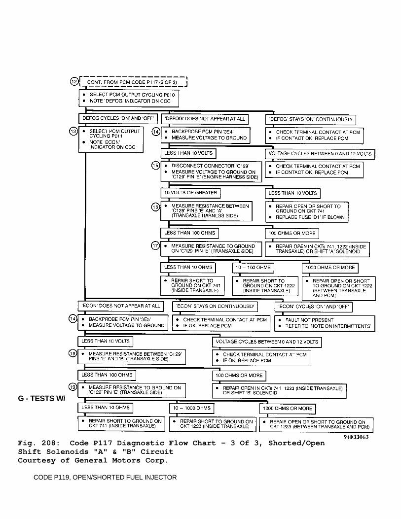
G - TESTS W/CODES - 4.6LArticle Text (p. 253)1995 Cadillac ConcoursFor Ace Mechanics 123 Main Street San Diego Ca 92126
Fig. 208: Code P117 Diagnostic Flow Chart - 3 Of 3, Shorted/OpenShift Solenoids "A" & "B" CircuitCourtesy of General Motors Corp.
CODE P119, OPEN/SHORTED FUEL INJECTOR

G - TESTS W/CODES - 4.6LArticle Text (p. 254)1995 Cadillac ConcoursFor Ace Mechanics 123 Main Street San Diego Ca 92126
PCM contains a General Field Effect Transistor Driver (GFD)that control the 8 fuel injector drivers. GFD detects circuit problemswith any of the 8 fuel injectors. If any circuit exists, PCM setstrouble code and also sets the second digit of parameter PD17 HI (1)and disables the faulty injector of the engine cycle.
Test Conditions Codes P016 and P035 not set. Engine cranked during ignitioncycle and fuel pump feedback greater than 10 volts.
Failure Conditions Injector circuit fault detected for .5 second.
Action Faulty injector disabled for engine run cycle.
NOTE: Test numbers refer to numbers on diagnostic chart.
1) Checks for intermittent. If second digit of PD17 is zero,fault is not present. PCM snapshot should show PD17 second digit as"1". 2) Checks for short to ground on circuit No. 339 or 439. 3) Open may be caused by poor injector harness connectorcontact. Check terminal contact. 4) Use fuel injector override to pinpoint faulty injectorcircuit. Disabling one injector would normally create a noticeabledifference in engine RPM or idle quality. 5) Checks for open or short to ground in circuit to PCM. 6) Checks injector resistance at engine temperature when thecondition occurs. Injector resistance will normally increase withincreasing engine temperature. Normal injector resistance should be 8-25 ohms. 7) Checks if problem is with injector or fuel rail harness. 8) Checks if problem is shorted injector or a short in fuelrail harness. 9) Checks for open or high resistance in fuel injector railharness or open or high injector resistance.

G - TESTS W/CODES - 4.6LArticle Text (p. 255)1995 Cadillac ConcoursFor Ace Mechanics 123 Main Street San Diego Ca 92126
Fig. 209: Code P119 Schematic, Open/Shorted Fuel InjectorCourtesy of General Motors Corp.

G - TESTS W/CODES - 4.6LArticle Text (p. 256)1995 Cadillac ConcoursFor Ace Mechanics 123 Main Street San Diego Ca 92126
Fig. 210: Code P119 Diagnostic Flow Chart - 1 Of 2, Open/Shorted FuelInjectorCourtesy of General Motors Corp.

G - TESTS W/CODES - 4.6LArticle Text (p. 257)1995 Cadillac ConcoursFor Ace Mechanics 123 Main Street San Diego Ca 92126
Fig. 211: Code P119 Diagnostic Flow Chart - 2 Of 2, Open/Shorted FuelInjectorCourtesy of General Motors Corp.
CODE P131, ACTIVE KNOCK SENSOR FAILURE

G - TESTS W/CODES - 4.6LArticle Text (p. 258)1995 Cadillac Concours
This test checks the knock sensor's ability to detect aknock. PCM adds an increasing level of spark that should causedetonation and sees if knock sensor detects knock. If knock is notdetected, Code P131 will set.
Test Conditions MAP value not varying by more than 7.8 kPa (VIN 9) or 10 kPa(VIN Y) at steady state operation. IAT value greater than 30øC andcoolant temperature at 40øC or greater. Battery voltage at 11 volts orgreater. Engine speed at greater than 1200 RPM for at least 2 seconds.
Failure Conditions Spark value of 0.3 degrees (VIN Y) or 3 degrees (VIN 9) willincrement until a maximum of 21 degrees is reached. If knock is notdetected for one second at maximum spark, Code P131 will set.
NOTE: Test numbers refer to numbers on diagnostic chart.
1) Checks if Code P132 was set due to circuit problem. 2) Checks knock sensor's ability to detect an induced spark.
Fig. 212: Code P131 Schematic, Active Knock Sensor FailureCourtesy of General Motors Corp.

G - TESTS W/CODES - 4.6LArticle Text (p. 259)1995 Cadillac ConcoursFor Ace Mechanics 123 Main Street San Diego Ca 92126
Fig. 213: Code P131 Diagnostic Flow Chart, Active Knock SensorFailureCourtesy of General Motors Corp.
CODE P132, KNOCK SENSOR CIRCUIT FAILURE
This test checks for knock sensor wiring problem. If circuitNo. 496 becomes open or shorted, voltage will either increase togreater than 4.2 volts or drop to less than 0.3 volt. If either ofthese conditions are met for 0.4 second, Code P132 will set.
Test Condition Coolant temperature at greater than 104øF (40øC) and batteryvoltage at 11 volts or greater.
Failure Conditions Knock sensor feedback voltage at greater than 4.48 volts 9(VIN 9) or 4.2 volts (VIN Y), or less than 0.3 volts (VIN Y & 9).
Action PCM turns on MIL.
NOTE: Test numbers refer to numbers on diagnostic chart.
1) Checks if Code P035 is also present. A REF LO problem cancause other ignition problems. 2) Checks for proper operating voltage of 0.3-4.2 volts at

G - TESTS W/CODES - 4.6L
PCM terminal 1A13. 3) Checks circuit No. 496 for short to ground. If circuit isokay, sensor is faulty. 4) Checks for short to voltage in circuit No. 496. 5) Checks circuit No. 496 for open.
Fig. 214: Code P132 Schematic, Knock Sensor Circuit FailureCourtesy of General Motors Corp.

G - TESTS W/CODES - 4.6LArticle Text (p. 261)1995 Cadillac ConcoursFor Ace Mechanics 123 Main Street San Diego Ca 92126
Fig. 215: Code P132 Diagnostic Flow Chart, Knock Sensor CircuitFailureCourtesy of General Motors Corp.
CODE P137, LOSS OF ABS/TCS DATA
This test checks for loss of or invalid ABS/TCS serial datato PCM. When such condition exists for 5 seconds, Code P137 will set.
Test Conditions Code P012 not set. Engine speed at 500 RPM or greater for 20seconds.
Failure Condition
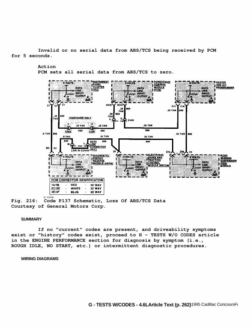
G - TESTS W/CODES - 4.6LArticle Text (p. 262)1995 Cadillac ConcoursFor Ace Mechanics 123 Main Street San Diego Ca 92126
Invalid or no serial data from ABS/TCS being received by PCMfor 5 seconds.
Action PCM sets all serial data from ABS/TCS to zero.
Fig. 216: Code P137 Schematic, Loss Of ABS/TCS DataCourtesy of General Motors Corp.
SUMMARY
If no "current" codes are present, and driveability symptomsexist or "history" codes exist, proceed to H - TESTS W/O CODES articlein the ENGINE PERFORMANCE section for diagnosis by symptom (i.e.,ROUGH IDLE, NO START, etc.) or intermittent diagnostic procedures.
WIRING DIAGRAMS

G - TESTS W/CODES - 4.6LArticle Text (p. 263)1995 Cadillac ConcoursFor Ace Mechanics 123 Main Street San Diego Ca 92126
Fig. 217: 4.6L (VIN Y & 9) PCM Wiring Diagram (1 Of 3)

G - TESTS W/CODES - 4.6LArticle Text (p. 264)1995 Cadillac ConcoursFor Ace Mechanics 123 Main Street San Diego Ca 92126Fig. 218: 4.6L (VIN Y & 9) PCM Wiring Diagram (2 Of 3)

G - TESTS W/CODES - 4.6LArticle Text (p. 265)1995 Cadillac ConcoursFor Ace Mechanics 123 Main Street San Diego Ca 92126Fig. 219: 4.6L (VIN Y & 9) PCM Wiring Diagram (3 Of 3)
END OF ARTICLE