tests of reinforced concrete t-beams. series of 1906,
TRANSCRIPT

IL L I N 0 I SUNIVERSITY OF ILLINOIS AT URBANA-CHAMPAIGN
PRODUCTION NOTE
University of Illinois atUrbana-Champaign Library
Large-scale Digitization Project, 2007.
T$ OFP
)F 1906
d... ~
IU
/
* <~
I IIII
U
I *
HIS BULLETIN is the twelftheof a series of bulletins pub-A lishied by the Engineering Experiment Station of the
UniTversity- of Illinois. The Engineering ExperimentStation was established by actoi of the Board of Trus-
tees Deicember 8, 1908. It is the pirpose of the Station to carryon investigations along various lines of engineering, and to studyproblemsi pf importanice to professional engineers and to the man-ufacturing, railwayi mining, construcional and industrial inter-ests of the state.
The control of the Engineering Experiment Station is vestedin the leads of the several departmentsa of the College of En-gineering. These constitute the Station Staff, and with the Di-rector determine the character of the investigations to be under-taken. The work is carried oi under the supervision of the Staff;sometimes by a Fellow Ltas graduate work, sometimes by a mem-ber of the instructional force of the College of Engineering, butmore frequently by a l investigator belonging to the Station Corpe.
.4~.
* I~ jC-
1 ~ I
U~ /
A
i '* ''1<
. . '"'
, -*: -
*y '^;' 1
^-.A.*.;
1'
^""i
8!£
1'
UNIVERSITY OF ILLINOIS
ENGINEERING EXPERIMENT STATION
BULLETIN No. 12. FEBRUARY 1907
TESTS OF REINFORCED CONCRETE T-BEAMSSERIES OF 1906.
BY ARTHUR N. TALBOT, PROFESSOR OF MUNICIPAL AND SANITARY
ENGINEERING AND IN CHARGE OF THEORETICAL
AND APPLIED MECHANICS.
CONTENTS.
I. INTRODUCTION.Page.
1. Preliminary ................. ..... ............. ... 3
2. Scope of Tests.......... ....... .................. 3
3. A cknowledgm ent ........... ........................... 4
II. RESISTANCE OF T-BEAMS TO FLEXURE.
4. General ........................... ....... . 4
5 . N otation ......... .. .... ....... .. .. . . . . ......... 5
6. Longitudinal,Tensile and Compressive Stresses,and
Location of Neutral Axis.-Approximate Solution 6
7. W eb S tresses....... ........ ............................ 9
8. Integrity of Flanges ............... ...... ..... . ... 11
9. M ethod of Tjeatm ent............... . ............... 12
10. Other Formulas for T-beams .......................... 12
III. MATERIALS, TEST PIECES, AND METHODS OF TESTING.
11. M aterials ..... ........... . ............ .... ..112. Test Specimens.............. . .... ...... ...... 1413. Forms ................ ..... . ..................... * .1714. Fabrication and Storage .............................. 17
15. M ethod of Testing .................... ..... .... ............ 18
2 ILLINOIS ENGINEERING EXPERIMENT STATION
IV. EXPERIMENTAL DATA AND DISCUSSION.
Page
16. Cube and Cylinder Test Data ... .................... 1917. Deflection Diagrams......... . ............ 1918. Phenomena of Tests .............. ...... .... 2019. Tension in Steel ......... ...... ................. 2420. Compression in Concrete............... ..... 2521. Web Stresses ......................... . 2622. Beam Deflection ......... ..... ................ ... 2823. Position of Neutral A xis......... ........ ........ 2824. Applicability of Results ......... ..... .... ..... 2925. Sum m ary .......... .. . ............... .............. 30
Deflection Diagram s ......... ....... ................. 32
TALBOT-TESTS OF REINFORCED CONCRETE T-BEAMS
I. INTRODUCTION.
1. Preliminary.-The series of tests on T-beams hereindescribed was undertaken with two objects in view,-to de-termine whether the width of slab within the limit used in theexperiments is a controlling element in the strength of thebeam, and to test the efficacy of vertical reinforcing stirrups inresisting web stresses. °
When a reinforced concrete floor and its supporting beamsare built as one piece, the resulting composite structure forms asystem of T-shaped beams. There are differences of opinion onthe action of the T-beams so formed, and also differences as tothe width of flange or floor which may be considered to contributeto the strength and stiffness of the beam. T-shapes may also beused in the design of bridge girders and other structures forspecial conditions. The large amount of reinforcement whichmay be put into a T-beam without encroaching on the com-pressive strength of the concrete too far and the resulting highweb stresses developed in the stem of the T-beam, make theT-beam an advantageous form of test piece for determining theefficacy of various forms and amounts of web reinforcement. Itis felt that this feature of T-beam testing is, in itself, sufficientreason for the conduct of tests on T-beams.
2. Scope of Tests.-Three top widths of beam were used,equal, respectively, to two, three, and four times the width of thestem of the beam. The beams were reinforced verticallywith U-shaped stirrups. One size and spacing of stirrupswas used. To insure that failure woull not occur by slip-ping of the vertical reinforcement in the concrete, the stir-rups were made of deformed bars. The amount of longitudinalreinforcement was made proportional to the width of flange ofthe beam. Both mild steel plain round rods and high-carbonJohnson corrugated bars were used for the longitudinal reinforce-ment, as it was not known whether the point of elastic limit ofthe metal would control the amount of load or method of failure.As no data on the amount of the web stresses which may beresisted by vertical stirrups were available and as little seemedto be known on the effect of the width of flange or slab, thebeams were designed to give considerable latitude in the resultsThe series was considered as preliminary and leading to a set of

ILLINOIS ENGINEERING EXPERIMENT STATION
tests which should include various forms and amounts of webreinforcement.
3. Acknowledgment.-The investigation was made in theLaboratory of Applied Mechanics of the University of Illinois asa part of the work of the University of Illinois EngineeringExperiment Station. Assistance in the tests and in the calcula-tions was given by F. S. Hewes and C. A. Hewes, senior studentsin civil engineering, class of 1906, who used the results in theirthesis. Immediate supervision of the work of making the beamsand conducting the tests was given by D. A. Abrams, Assistant inthe Engineering Experiment Station. Acknowledgment is alsomade to W. R. Robinson, Assistant in the Engineering Experi-ment Station, for aid in the preparation of this bulletin. Thestone, sand and cement used in making the beams were furnishedby the Joint Committee on Concrete and Reinforced Concrete.
An analysis of some of the elements of flexure of T-beamswill be given. This will be followed with a description of thetest pieces and method of testing, the experimental data, and adiscussion of the results.
II. RESISTANCE OF T-BEAMS TO FLEXURE
4. General.-The analysis of the resistance of T-beams toflexure -may be made to follow the general lines of analysis forrectangular beams. If the tensile strength'of the concrete be notconsidered at sections having a maximum bending moment andif the flange or slab extends down to the neutral axis of the beam,the resisting moment may be expected to be the same as that fora rectangular beam of width equal to the width of the flange, pro-vided, of course, that the integrity of the plane section is conserved.If the flange does not extend down to the neutral axis. anexamination of the effect of the omission of apart of the com-pression area must be made to find whether the formula forrectangular beams is still applicable. With relatively shallowflanges some modification of the formulas used in rectangularbeams for determining neutral axis, tensile and compressivestresses, and resisting moment may be required. In thedetermination of web stresses, a slightly different treatment willbe needed on account of the narrowed width of beam throughthe stem. The stiffness and integrity of the flange next to itsjunction with the stem will require investigation.
TALBOT-TESTS OF REINFORCED CONCRETE T-BEAMS
In the treatment here given, the usual assumptions of beamaction noted in Bulletin No. 4 will be made. These include the
assumptions that a plane section before bending will remain aplane section after bending and that tensile stresses in the con-
crete at the section of greatest bending moment may be neglected.The stresses developed in the flange' to conserve the plane sectionwill be considered separately. The general treatment will followthat given in Bulletin No. 4 of the University of Illinois Engi-neering Experiment Station, under I. RESISTANCE OF BEAMS TO
FLEXURE, and equations from this source will be quoted withoutdemonstration. The term "inclosing rectangle" will be used todenote the rectangle inclosing the flange of the T-beam and thestem down to the centroid of the reinforcing bars.
5. Notation.-The following notation will be used, Fig. 1:h = thickness of flange or slab of T-beam.b = breadth of flange or slab of T-beam.b'= breadth of stem of T-beam.d = distance from the compressive face to the centroid of the
longitudinal reinforcement.d'-- distance from the center of the longitudinal reinforcement
to center of gravity of compressive stresses.A = area of cross section of longitudinal reinforcement.bd= area of inclosing rectangle (rectangle inclosing flange and
stem of T-beam down to center of the longitudinalreinforcement).
p =d ratio of area of longitudinal reinforcement to area ofinclosing rectangle.
o = circumference or periphery of one reinforcing bar.m = number of reinforcing bars.E. = modulus of elasticity of steel.E- = initial modulus of elasticity of concrete in compression, a
term defined in Bulletin No. 4.
n = = ratio of two moduli.
f-= tensile stress per unit of area in longitudinal reinforcement.
c = compressive stress per unit of area in most remote fiberof concrete.
c'= compressive stress per unit of area which causes failure bycrushing.
ILLINOIS ENGINEERING EXPERIMENT STATION
e = deformation per unit of length in the longitudinal reinforce-ment.
e-= deformation per unit of length in most remote fiber of theconcrete.
e'c = deformation per unit of length when crushing failure occurs;i. e., ultimate or crushing deformation.
S-- = ratio of deformation existing in most remote fiber to$C ultimate or crushing deformation.
k = ratio of distance between compression face and neutral axisto distance d.
z = distance from compression face to center of gravity of com-pressive stresses.
M= resisting moment at the given section.8 = horizontal tensile stress per unit of area in the concrete.t = diagonal tensile stress per unit of area in the concrete.u = bond stress per unit of area on the surface of the reinforcing
bar.v = vertical shearing stress and horizontal shearing stress per
unit of area in the concrete.
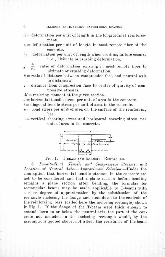
FIG. 1. T-BEAM AND INCLOSING RECTANGLE.
6. Longitudinal, Tensile and Compressive Stresses, andLocation of Neutral Axis.--Approximate Solution.-Under theassumption that horizontal tensile stresses in the concrete arenot to be considered and that a plane section before bendingremains a plane section after bending, the formulas forrectangular beams may be made applicable to T-beams witha close degree of approximation by the substitution of therectangle inclosing the flange and stem down to the centroid ofthe reinforcing bars (called here the inclosing rectangle) shownin Fig. 1. If the flange of the T-beam were thick enough toextend down to or below the neutral axis, the part of the con-crete not included in the inclosing rectangle would, by theassumptions quoted above, not affect the resistance of the beam

TALBOT-TESTS OF REINFORCED CONCRETE T-BEAMS
to flexure. If the flange does not extend to the neutral axis, apart of the compression area assumed to exist for the inclosingrectangle is not available in the T-beam, but the portion so cutoff has, by reason of its proximity to the neutral axis, a compar-atively small influence upon the flexural action of the beam. Theeffect is so little that we may, within certain limits of propor-tions, substitute the inclosing rectangle for the T-section indetermining the position of the neutral axis, the tensile stress inthe reinforcement, the compressive stress in the most remotefiber of the concrete, and the resisting moment of the section.
For this approximation, the formulas given in Bulletin No. 4for the proportional depth of the neutral axis may be repeated :
For a constant modulus of elasticity in the concrete (straight-line stress-deformation relation),
k = 2 pn + p'n -pn ........................... (10)
When the deformation in the most remote fiber is equal toone fourth of the ultimate or crushing deformation (q-=-4), acondition approaching that found in beams of the usual per-centage of reinforcement, the general equation for neutral axisreduces to,
k= pn~~ i p* 2n- pn....................(11)
Equation (8) of Bulletin No. 4 may be used for the general caseand (9) when the concrete is at the limit of the compressivestrength.
The diagram given on page 16 of Bulletin No. 4 will be usefulin determining the position of the neutral axis if equation (11)is to be used. With 1% reinforcement, for a ratio n equal to 12,k will be .40; for a ratio A equal to 15, k will be .43.
For a beam in which the compressive stress developed is lessthan the ultimate strength of the concrete (and this conditioncovers all the usual cases of T-beams), the formula for the resist-ing moment of the beam may best be expressed in terms of thetensile stress in the reinforcing bars, as given in the two equa-tions:
M = Af (d- z)..................................... (12)= A fd' ............ ...... ....... .............. (13)
ILLINOIS ENGINEERING EXPERIMENT STATION
If k = .40, or .43, the latter equation may be written M = .86A / d, and this equation for the resisting moment of the T-beammay be used with sufficient accuracy for many purposes, even forquite a range of reinforcement. If the bending moment isknown, the stress in the steel may be calculated by substitutingthe value of the bending moment for X in equation (13) or in thereduced form M = .86 A f d. The effect of substituting theinclosing rectangle for the exact T-shape in determining theposition of the neutral axis and the center of the compressivestresses is so slight that the error may be neglected and the aboveformulas used when the flange extends at least two thirds of thedistance to the neutral axis or, say, when the thickness of theflange is at least one fourth of the depth of the beam. Even forthinner flanges the error in the use of these formulas will not belarge.
Values for compressive stresses in T-beams are not of verygeneral usefulness since the percentage of reinforcement (basedon the inclosing rectangle) will generally not be large and theco upressive stresses iay therefore not need to be considered andmay be sufficiently guarded by limiting the percentage of re-inforcement. To illustrate, if in a T-beam made up of a beamand its connecting portion of the floor a width equal to fourtimes the width of the beam itself be considered to be tributaryto the T-beam and if the area of the reinforcing bars is 4% of thearea inclosing the stem of the T-beam (b'd, of Fig. 1), this re-inf6rcement will be only 1% of the inclosing rectangle of theassumed T-beam. Under conditions of good construction, thecompressive stress developed in the concrete, would, as hasbeen shown for rectangular beams, be well below any danger of acompression failure. This amount of steel is larger than wouldordinarily be used in such construction.,
If, however, it is desired to compute the compressive stress,an approximate solution may be made by equation (15) ofBullet'in No 4,
. 2Af 1 - q_ 2pf 1 - sqc kbd 1- i q k 1 -T q *
where b and p refer to the inclosing rectangle. For the con-
ditions of T-beams the fraction 1 will likely range between1 -

TALBOT-TESTS OF REINFORCED CONCRETE T-BEAMS
.92 and .97, so that its use or non-use does not affect the resultsmaterially.
There is a greater proportional error in the use of equation(15) for beams in which the flange does not extend down to theneutral axis than there is in the use of equation (13), but as thepurpose is only to find whether a limiting value is exceeded, thelimits for depth of flange used with equation (13) may be con-sidered allowable. This is further borne out by the fact that infloor systems a width of floor even greater than here used willgenerally be tributary to the T-beam, and hence the compressivestress will be lower than for an assumed ratio of 4.
7. Web Stresses.-Bond, Shear, and Diagonal Tension.-InT-beams the bond stresses developed are practically the same aswould be found with the same steel in a rectangular beam. Theshearing stresses developed and the corresponding diagonal ten-sile stresses are higher, since the width of stem is relativelysmall; and even with a moderate amount of reinforcement theresistance to web stresses may constitute the weakest element ofthe beam.
The. bond stress developed in a T-beam when the longitudinalreinforcing rods are laid horizontally throughout the length ofthe beam may be determined by equation (17) of Bulletin No. 4,(p. 19),
Vu - mod' ............. .. .......... . ... (17)
where u is the bond unit-stress developed, V is the total externalvertical shear, m is the number of reinforcing bars, o is theeffective circumference or periphery of one bar, and d' is thedistance from the center of the longitudinal reinforcement to thecenter of gravity of the compressive stresses. The only approxi-mation to be made is in getting the value of d'. As in the pre-ceding article, d' may be taken to be d (1 - .34 k), and k may beobtained as before suggested by the use of the method of rec-tangular beams with the width of the beam taken as that of theinclosing rectangle. For most conditions d' may be called .86d.
The reasoning for the determination of vertical and horizontalshearing stresses given on page 20 of Bulletin No. 4 is directlyapplicable to T-beams, and formula (18) will give the horizontalshearing unit-stress (and therefore its equal, the vertical shear-
ILLINOIS ENGINEERING EXPERIMENT STATION
ing unit-stress), if we use in it the width Y', the width of thestem of the T-beam.
v = ............ . .................. ............ (18)
In equation (18) v is either the horizontal or the vertical shear-.ing unit-stress, the two shearing unit-stresses being always equal.For most conditions d' may be taken as .86d, as in the last para-graph. The amount of the vertical shearing unit-stress developedin T-beams may be much higher than in ordinary rectangularbeams, but it will be well below the ultimate shearing strengthof the concrete.
The diagonal tensile stress in the stem of the T-beam is afunction of the shearing stress and the horizontal tensile stressin the concrete. As the horizontal tensile stresses may not bewell determined, it seems best for our purpose to use the hori-zontal and vertical shearing stresses as a means of comparison ofthe diagonal tensile stress developed. If part or all of the reinforc-ing bars are bent up at the ends, the problem is further compli-cated. The beams described in this bulletin- were reinforcedwith vertical stirrups, and as the concrete itself failed to resistthe diagonal tension at points well below the maximum load puton the beam, the resistance of the concrete to diagonal tensionwill be disregarded for these tests and the effect of the verticalstirrups studied.
Two forms of metallic web reinforcement are used to coun-teract the diagonal tension: (1) bending the reinforcing bars orstrips sheared from them into a diagonal position, and (2) verti-cal stirrups carried under and around the longitudinal reinforce-ment and extended upward to the top of the beam or to someanchorage. The T-beams tested were reinforced with verticalstirrups, and hence this form of web reinforcement will be con-sidered further.
The diagonal tension existing in the web may be resolved intohorizontal and vertical components. Considering the longitudi-nal bars to be all horizontal, we may expect, when the bond re-sistance is sufficient, that the horizontal component will be takenby the longitudinal reinforcement. Considering that the test haspassed the point where the concrete of the web resists the diagonaltension, we may count that the whole vertical component of the
TALBOT-TESTS OF REINFORCED CONCRETE T-BEAMS
web stresses is taken by the stirrups. The amount of this verticalcomponent per unit of length of beam is for the T-beams equal tothe horizontal shear for the width of the stem as given by
Vequation (18), and vb' = will give the rate of vertical stress
per unit of length of beam which will go to the stirrups. If thestirrups are 6 inches apart, the stress to be taken by the twoprongs of the stirrup will be 6 vb'. This calculation is on thebasis of a test loading which gives a constant shear from supportto load point, as, for example, a loading at the one-third points.For a uniformly distributed load, the value vb' will be the rate ofstress at a given section. To illustrate further, for a T-beamhaving a width of stem of 8 in., and d' = 8.6 in., and a load of60000 lb., V= 30000 lb., and v = 437 lb. per sq. in. With stir-rups 6 inches apart the total stress on one prong of the stirrupwill be 10 500 lb. These calculations do not take into accountthe resistance to bending of the reinforcing bars themselves.In the T-beams having also a part of the bars bent up, in orderto avoid complicated calculations and to give a general com-parison, the same formulas will be used herein, although theresults are not an accurate measure of the stresses produced.
8. Integrity of Flanges.-In discussions on T-beams it is fre-.quently stated that the thickness of the flange must be at least onehalf as greatas the width of the stem or rib, in order that. the shear-ing stresses at the junction of the flange and stem may not exceedthose in the lower part of the stem. As the actual shearingstresses in both sections are well within the shearing strength ofthe concrete, there is no danger of failure by shear in eithersection, using the term shear in its strict sense. In the stem wehave used the shearing unit-stress as a measure or method ofcomparison for the diagonal tensile stresses. In the flange thesestresses do not need consideration. Longitudinal shearing stressesin the flange, then, will not require consideration, and the limitof depth given above is unnecessary.
Another statement sometimes made is that the compressivestress in the flange varies across the width of the flange from amaxifnum amount next to the stem to zero at the edge of theflange. A little consideration will show that this cannot be true.The flange must transmit stress laterally to its edges, acting in a

ILLINOIS ENGINEERING EXPERIMENT STATION
way as a beam with a load applied longitudinally and horizon-tally. The width of the overhang of the flange may be consideredto be the span of this cantilever beam, and the distance from theload to the support (one-third the span 'length in the beamstested) may be thought of as the depth. Evidently this will be avery stiff beam, and the result will be a close approach to uni-formity of compressive stress at points across the width of theflange. Little variation from a plane section may therefore beexpected, the change that may exist being produced more largelyby other causes. Of course, there must be a limit to thisassumed integrity of the cross section, but for T-beams with theordinary amount of reinforcement the compressive stress devel-oped is small and the variation may generally be neglected.
As usually constructed, the floor, and hence the flange ofthe T-beam, will have reinforcement at right angles to the stem.This will resist a breaking of the flange next to the stem andassist in giving the whole flange the curved shape which thebeam takes when the load is applied.
9. iMethod of Treatment.-For the investigation hereinrecorded, the preceding method of analysis will be used. TheT-beam will be treated as a rectangular beam of the dimensionsgiven by the inclosing rectangle, when tensile, compressive, andbond stresses are under consideration. The width of the stemwill be considered to enter into calculations for shear and for.diagonal tension. The integrity of the cross section will beinvestigated somewhat, and the bearing of the approximationinvolved in the above assumptions will be looked into.
10. Other Formulas for T-beams.-If it is desired to takeinto account the exact section above the neutral axis the followingformula for the proportionate depth of the neutral axis may beused, if we consider q = 0, or if we use a straight-line modulus ofelasticity. Other values of q may be used.
k 2 pn ( - (1- [pn ( 1-p ) Y - 1d ................ (10')
For a beam with 1% reinforcement and having a ratio of
depth of flange to effective depth of steel of , using forL iC) of

TALBOT-TESTS OF REINFORCED CONCRETE T-BEAMS 18
comparison n = 15, this formula gives k = .44, and the approxi-
mate method previously described gives k = .42. For = -,
k - .46. It is easily seen that the effect of this difference uponthe calculated resisting moment of the beam (when based ontension in the steel) is small.
III. MATERIALS, TEST PIECES, AND METHOD OF TESTING.
11. Materials.-The stone was a good quality of rather hardlimestone from Kankakee, Illinois, ordered screened through a1-in. screen and over a ¼-in. screen. It contained 45% to 50%
voids and weighed 85 pounds per cubic foot. In the determina-tion of the voids of both stone and sand, the material was pouredslowly into water so that the voids became filled with water andno air was caught.
The sand was of good quality from near the Wabash river atAttica, Indiana. It was fairly clean, sharp and well graded, con-tained 28% voids, and weighed 115 lb. per cu. ft. Table 1 givesthe results of a mechanical analysis of this sand.
TABLE 1.
MECHANICAL ANALYSIS OF SAND.
Sieve No.
410203074
100
Per centPassing
10073361252
The cement used was furnished by the Joint Committee on
Concrete and Reinforced Concrete. It was made up of a mixtureof five standard American portland cements,, selected and mixedby the manufacturers and was of excellent quality.
The concrete was made of the proportions of 1 of cement, 2 of
sand, and 4 of stone, measured by loose volume. The mixing was
done and the beams made by men skilled in concrete work. Care
was taken in measuring, mixing, and tamping, to secure as
uniform a concrete as possible. The mixing was done with
ILLINOIS ENGINEERING EXPERIMENT STATION
shovels by hand; the stone having been wetted a day or so beforebeing used. The sand and cement were first mixed dry, thestone being then added and the mass mixed until uniform inappearance. Water was added in such proportion that thetamping of the central portion of the beam really amounted to achurning action.
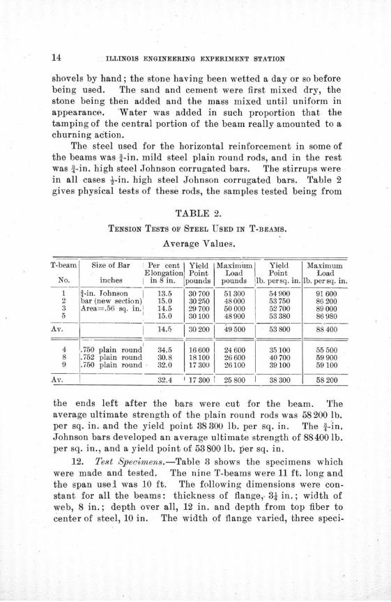
The steel used for the horizontal reinforcement in some ofthe beams was 1-in. mild steel plain round rods, and in the restwas 1-in. high steel Johnson corrugated bars. The stirrups werein all cases J-in. high steel Johnson corrugated bars. Table 2gives physical tests of these rods, the samples tested being from
TABLE 2.
TENSION TESTS OF STEEL USED IN T-BEAMS.
Average Values.
T-beam Size of Bar I Per cent Yield Maximum YieldElongation Point Load Point
No. inches I in 8 in. pounds pounds lb. persq. in.
1 i-in. Johnson 13.5 30 700 51300 549002 bar (new section) 15.0 30 250 48 000 53 7503 Area=.56 sq. in.I 14.5 29700 50000 527005 15.0 30100 48900 53380
Av. 14.5 30 200 49 500 53 800
4 .750 plain round 34.5 16600 24600 35 1008 .752 plain round 30.8 18100 26600 407009 .750 plain round 32.0 17 300 26100 39 100
Av. 32.4 17 300 25 800 38 300
MaximumLoad
lb. per sq. in.
91 60086 20089 00086980
88400
55 5005990059 100
58 200
the ends left after the bars were cut for the beam. Theaverage ultimate strength of the plain round rods was 58 200 lb.per sq. in. and the yield point 38 300 lb. per sq. in. The 4-in.Johnson bars developed an average ultimate strength of 88400 lb.per sq. in., and a yield point of 53800 lb. per sq. in.
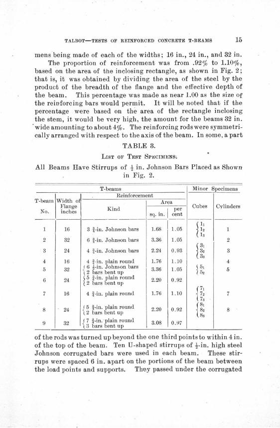
12. Test Specimens.-Table 3 shows the specimens whichwere made and tested. The nine T-beams were 11 ft. long andthe span usel was 10 ft. The following dimensions were con-stant for all the beams: thickness of flange,-34 in.; width ofweb, 8 in.; depth over all, 12 in. and depth from top fiber tocenter of steel, 10 in. The width of flange varied, three speci-
TALBOT-TESTS OF REINFORCED CONCRETE T-BEAMS
mens being made of each of the widths; 16 in., 24 in., and 32 in.The proportion of reinforcement was from .92% to 1.10%,
based on the area of the inclosing rectangle, as shown in Fig. 2;that is, it was obtained by dividing the area of the steel by theproduct of the breadth of the flange and the effective depth ofthe beam. This percentage was made as near 1.00 as the size ofthe reinforcing bars would permit. It will be noted that if thepercentage were based on the area of the rectangle inclosingthe stem, it would be very high, the amount for the beams 32 in.
'wide amounting to about 4%. The reinforcing rods were symmetri-cally arranged with respect to the axis of the beam. In some, a part
TABLE 3.
LIST OF TEST SPECIMENS.
All Beams Have Stirrups of 1 in. Johnson Barsin Fig. 2.
Width ofFlangeinches
16
32
24
16
32
24
16
24
32
T-beamsReinforcement
Kind
3 a-in. Johnson bars
6 f-in. Johnson bars
4 f-in. Johnson bars
4 f-in. plain roundJ6 ½-in. Johnson bars
2 bars bent up5 f-in. plain round
( 2 bars bent up
4 f-in. plain round
i-in. plain roundbars bent up
4-in. plain roundbars bent up
Areaper
sq. in. cent
1.68
3.36
2.24
1.76
3.36
2.20
1.05
1.05
0.93
1.10
1.05
0.92
1.10
0.92
0.97
Placed as Shown
1Minor
Cubes
Specimens
Cylinders
1
2
3
4
5
7
8
of the rods was turned up beyond the one third points to within 4 in.of the top of the beam. Ten U-shaped stirrups of 4-in. high steelJohnson corrugated bars were used in each beam. These stir-rups were spaced 6 in. apart on the portions of the beam betweenthe load points and supports. They passed under the corrugated
T-beam
No.
1
2
3
4
5
6
7
8
9
Reinforcement
• lr -" __ _
ILLINOIS ENGINEERING EXPERIMENT STATION
3t/ 7 1 14-'ohnsa/ w v./fMJ~'~f/l /', ^
N-e 1- 6- Zlh,4n,, B ~/x3s,~i II I III . . . . . 'U _
I----------...._...- .---- ,
N- f - ~ 0-~.2"
VN 2 - S- - " A'o W 8<, a,., 6-/; 4"-/-4.Y3"/rm/r . 3- " " " _
i " ------ , i , .-- -n n ,y
I i i il i1 iI
g u,) 1.,,, I -.
i- i i '~ m-x-j Ti» II
I'3 i. - uf ;
L- = L-Li/^^
NO 7 - 4-'~¼~tnBs
N 40 8 - 2 8f
S iIII I II I I
Nl< '- ¢^-Sk/'s a/7 0o fs , •rl'.'/^i:4"l',' 4-/ "8t/P* ,Tt'frt',
, , ...... . ." ' ----11, ,1 ' , ..
A/ a g - /- rounda G ,U SIr-v, V'ru
, i i 1i t i i | ' .
• i", l i 6 _ •
- 41
N-2 - ---2 i
' ,2.. .ARRANGEMENT1 OF ,,IFOCEMN
I -i .I- 11i I•I I- I I
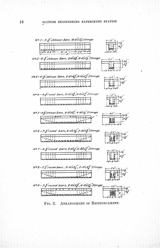
FIG. 2. ARRANGEMENT OF REINFORCEMENT.
TALBOT-TESTS OF REINFORCED CONCRETE T-BEAMS
reinforcing bars, alternate ones inclosing only the middle bars.In two of the 32-in. beams three '-in. Johnson corrugated barswere placed transversely in the upper side of the flange at andnear the load points. Fig. 2 shows the arrangement of thereinforcement in all of the beams. In some of the beams inwhich the reinforcing bars were placed in two layers, the upperbars sank down in the mortar until they were in contact withthe lower layer of bars.
Fourteen 6-in. cubes were tested. The numbering is thesame as that for the beams for which the batch was made. Seven8-in. cylinders were made in a similar manner.
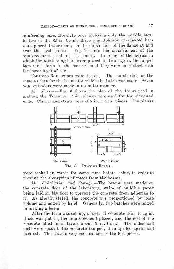
13. Forms.-Fig. 3 shows the plan of the forms used inmaking the T-beams. 2-in. planks were used for the sides andends. Clamps and struts were of 2-in. x 4-in. pieces. The planks
7Too I/ew n/a'd V'w
FIG. 3. PLAN OF FORMS.
were soaked in water for some time before using, in order toprevent the absorption of water from the beams.
14. Fabrication and Storage.-The beams were made onthe concrete floor of the laboratory, strips of building paperbeing laid on the floor to prevent the concrete from adhering toit. As already stated, the concrete wis proportioned by loosevolume and mixed by hand. Generally, two batches were mixedin making a beam.
After the form was set up, a layer of concrete 1-in. to 1I in.thick was put in, the reinforcement placed, and the rest of theconcrete filled in in layers about 3 in. thick. The sides andends were spaded, the concrete tamped, then spaded again andtamped. This gave a very good surface to the test pieces.
ILLINOIS ENGINEERING EXPERIMENT STATION
The forms were kept on until a day or so before testing thebeams, the beams being sprinkled twice daily in the meantime.The temperature of the room ranged from 600 to 70° F. during theperiod of storage.
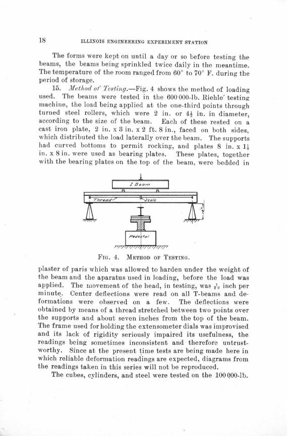
15. Method of Testing.-Fig. 4 shows the method of loadingused. The beams were tested in the 600 000-lb. Riehle' testingmachine, the load being applied at the one-third points throughturned steel rollers, which were 2 in. or 4j in. in diameter,according to the size of the beam. Each of these rested on acast iron plate, 2 in. x 3 in. x 2 ft. 8 in., faced on both sides,which distributed the load laterally over the beam. The supportshad curved bottoms to permit rocking, and plates 8 in. x 11in. x 8 in. were used as bearing plates. These plates, togetherwith the bearing plates on the top of the beam, were bedded in
FIG. 4. METHOD OF TESTING.
plaster of paris which was allowed to harden under the weight ofthe beam and the aparatus used in loading, before the load wasapplied. The movement of the head, in testing, was -y inch perminute. Center deflections were read on all T-beams and de-formations were observed on a few. The deflections wereobtained by means of a thread stretched between two points overthe supports and about seven inches from the top of the beam.The frame used for holding the extensometer dials was improvisedand its lack of rigidity seriously impaired its usefulness, thereadings being sometimes inconsistent and therefore untrust-worthy. Since at the present time tests are being made here inwhich reliable deformation readings are expected, diagrams fromthe readings taken in this series will not be reproduced.
The cubes, cylinders, and steel were tested on the 100000-lb.
TALBOT-TESTS OF REINFORCED CONCRETE T-BEAMS
Riehle' machine, the speed of the head being .1 inch per minute.The cubes and cylinders were bedded in plaster of paris beforetesting.
IV. EXPERIMENTAL DATA AND DISCUSSION.
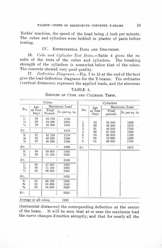
16. Cube and Cylinder Test Data.-Table 4 gives the re-sults of the tests of the cubes and cylinders. The breakingstrength of the cylinders is somewhat below that of the cubes.The concrete showed very good quality.
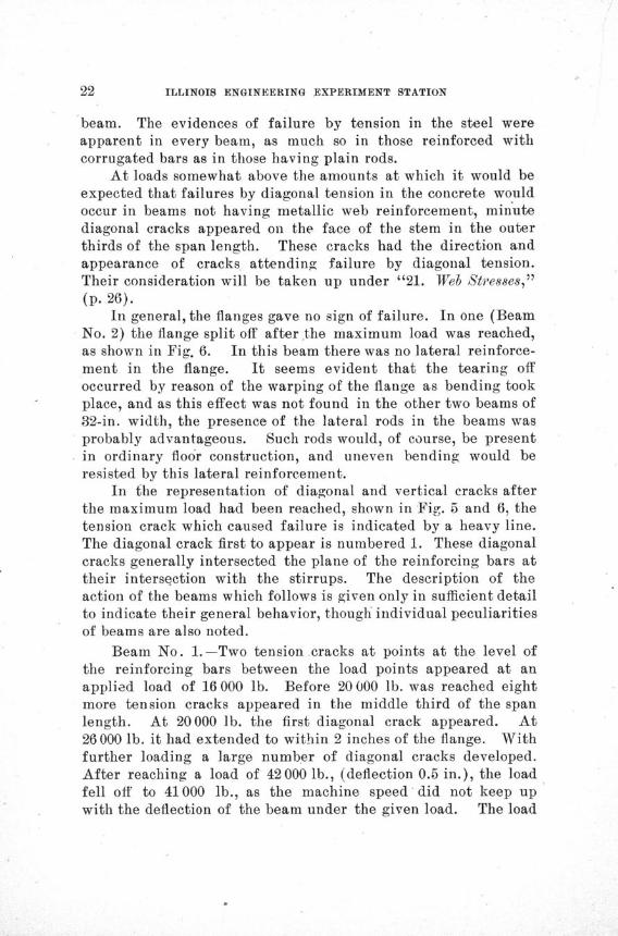
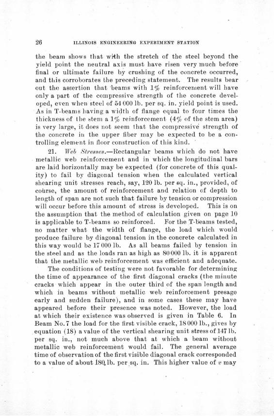
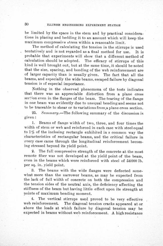
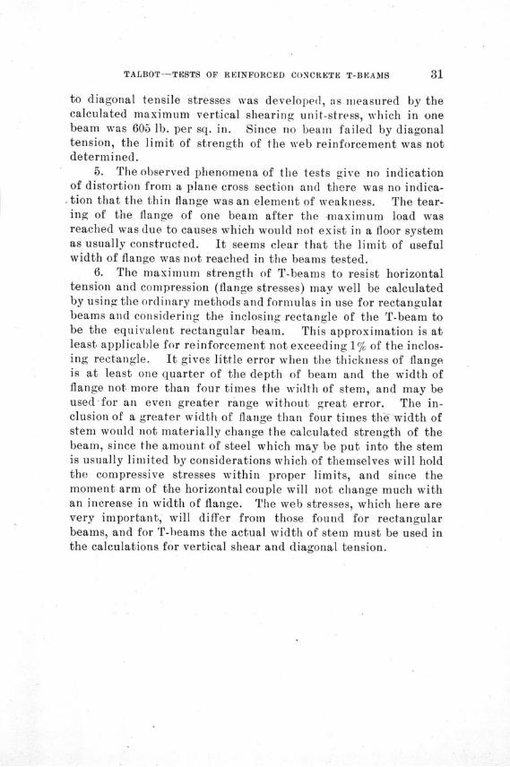
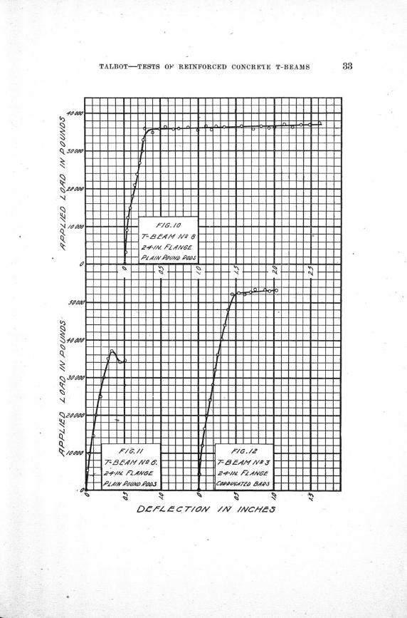
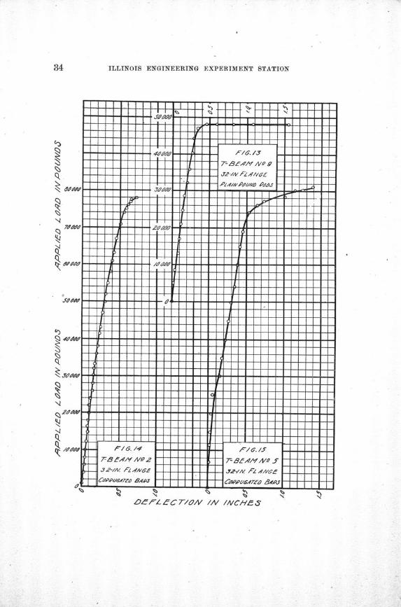
17. Dedleetion Diagrams.-Fig. 7 to 15 at the end of the textgive the load-deflection diagrams for the T-beams. The ordinates(vertical distances) represent the applied loads, and the abscissas
TABLE 4.RESULTS OF CUBE AND CYLINDER TESTS.
AgeNo. at Test
Days
11 5912 5918 59
Av.
32
3s
Av.
5152
Av.
717278
Av.
575757
5858
565656
81 548a 5483 54
Av.
CubesMaxir
TotalPounds
62 12084 69066 390
42 12049 62046 200
69 80081500
57 60071 10068 300
68 10055 60094 500
Average of all cubes,
aum Load
lb. per sq. in.
172023501840
1970
117013801280
1280
19402260
2100
160019801900
1830
189015402620
2020
No.
1234578
Av.
Ageat TestDays
63636159585654
CylindersMaximum Load
Totalpounds
95 00094 20088 20067 00060 00073 00088 000
lb. per sq. in.
1890187017601330119014501750
1610
1820
(horizontal distances) the corresponding deflection at the centerof the beam. It will be seen that at or near the maximum loadthe curve changes direction abruptly, and that for nearly all the
I
ILLINOIS ENGINEERING EXPERIMENT STATION
beams the load does not fall off materially until a considerabledeflection has been obtained. The stress-deformation curvesfound (not reproduced) show an abrupt change on the tensionside of the beam.
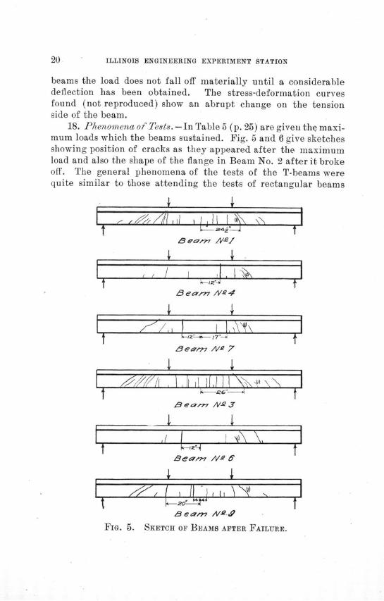
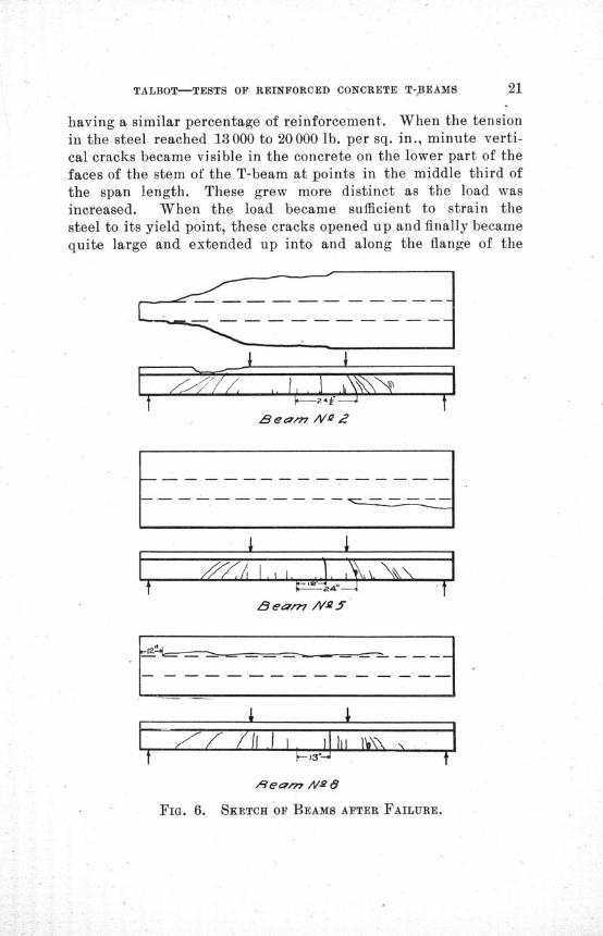
18. Phenomena of Tests.- In Table 5 (p. 25) are given the maxi-mum loads which the beams sustained. Fig. 5 and 6 give sketchesshowing position of cracks as they appeared after the maximumload and also the shape of the flange in Beam No. 2 after it brokeoff. The general phenomena of the tests of the T-beams werequite similar to those attending the tests of rectangular beams
T
Beamw /Vye
4 4If , 'i'i I^,
I ,
Seam7 ,- 7
4 4t ,, ,
Be,7iw N-e.,,n'-•' -Beam /V-" 3
\ 4
4 4
BealM /VA. E
FIG. 5. SKETCH OF BEAMS AFTER FAILURE.
TALBOT-TESTS OF REINFORCED CONCRETE T-BEAMS
having a similar percentage of reinforcement. When the tensionin the steel reached 13000 to 20000 lb. per sq. in., minute verti-cal cracks became visible in the concrete on the lower part of thefaces of the stem of the T-beam at points in the middle third ofthe span length. These grew more distinct as the load wasincreased. When the load became sufficient to strain thesteel to its yield point, these cracks opened up and finally becamequite large and extended up into and along the flange of the
Beaw N0 2
ae ,m ,a5"
^ ̂=-^==^B N-9^ _T -
I / / /1 .1I •., I i,,H 1^", , I-^ (-~13`41
, earn N- 6
FiG. 6. SKETCH OF BEAMS AFTER FAILURE.
f
ILLINOIS ENGINEERING EXPERIMENT STATION
beam. The evidences of failure by tension in the steel wereapparent in every beam, as much so in those reinforced withcorrugated bars as in those having plain rods.
At loads somewhat above the amounts at which it would beexpected that failures by diagonal tension in the concrete wouldoccur in beams not having metallic web reinforcement, minutediagonal cracks appeared on the face of the stem in the outerthirds of the span length. These cracks had the direction andappearance of cracks attending failure by diagonal tension.Their consideration will be taken up under "21. Web Stresses,"(p. 26).
In general, the flanges gave no sign of failure. In one (BeamNo. 2) the flange split off after the maximum load was reached,as shown in Fig. 6. In this beam there was no lateral reinforce-ment in the flange. It seems evident that the tearing offoccurred by reason of the warping of the flange as bending tookplace, and as this effect was not found in the other two beams of32-in. width, the presence of the lateral rods in the beams wasprobably advantageous. Such rods would, of course, be presentin ordinary floor construction, and uneven bending would beresisted by this lateral reinforcement.
In the representation of diagonal and vertical cracks afterthe maximum load had been reached, shown in Fig. 5 and 6, thetension crack which caused failure is indicated by a heavy line.The diagonal crack first to appear is numbered 1. These diagonalcracks generally intersected the plane of the reinforcing bars attheir intersection with the stirrups. The description of theaction of the beams which follows is given only in sufficient detailto indicate their general behavior, though individual peculiaritiesof beams are also noted.
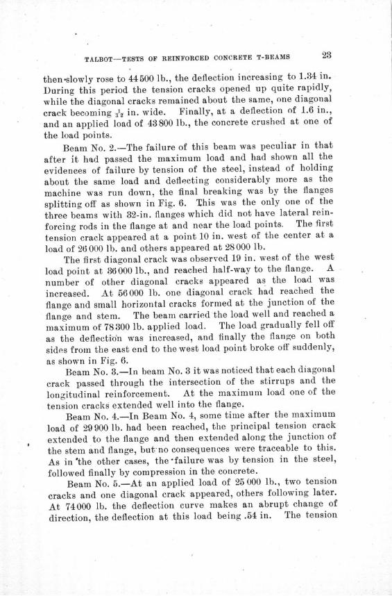
Beam No. 1.-Two tension cracks at points at the level ofthe reinforcing bars between the load points appeared at anapplied load of 16 000 lb. Before 20 000 lb. was reached eightmore tension cracks appeared in the middle third of the spanlength. At 20000 lb. the first diagonal crack appeared. At26 000 lb. it had extended to within 2 inches of the flange. Withfurther loading a large number of diagonal cracks developed.After reaching a load of 42000 lb., (deflection 0.5 in.), the loadfell off to 41000 lb., as the machine speed did not keep upwith the deflection of the beam under the given load. The load
TALBOT-TESTS OF REINFORCED CONCRETE T-BEAMS
then-slowly rose to 44500 lb., the deflection increasing to 1.34 in.
During this period the tension cracks opened up quite rapidly,
while the diagonal cracks remained about the same, one diagonal
crack becoming .y in. wide. Finally, at a deflection of 1.6 in.,
and an applied load of 43800 lb., the concrete crushed at one of
the load points.
Beam No. 2.-The failure of this beam was peculiar in that
after it had passed the maximum load and had shown all the
evidences of failure by tension of the steel, instead of holding
about the same load and deflecting considerably more as the
machine was run down, the final breaking was by the flanges
splitting off as shown in Fig. 6. This was the only one of the
three beams with 32-in. flanges which did not have lateral rein-
forcing rods in the flange at and near the load points. The first
tension crack appeared at a point 10 in. west of the center at a
load of 26000 lb. and others appeared at 28000 lb.
The first diagonal crack was observed 19 in. west of the west
load point at 36000 lb., and reached half-way to the flange. A
number of other diagonal cracks appeared as the load was
increased. At 56000 lb. one diagonal crack had reached the
flange and small horizontal cracks formed at the junction of the
flange and stem. The beam carried the load well and reached a
maximum of 78300 lb. applied load. The load gradually fell off
as the deflection was increased, and finally the flange on both
sides from the east end to the west load point broke off suddenly,
as shown in Fig. 6.Beam No. 3.-In beam No. 3 it was noticed that each diagonal
crack passed through the intersection of the stirrups and the
longitudinal reinforcement. At the maximum load one of the
tension cracks extended well into the flange.
Beam No. 4.-In Beam No. 4, some time after the maximum
load of 29 900 lb. had been reached, the principal tension crack
extended to the flange and then extended along the junction of
the stem and flange, but-no consequences were traceable to this.
As in'the other cases, the failure was by tension in the steel,
followed finally by compression in the concrete.
Beam No. 5.-At an applied load of 25 000 lb., two tension
cracks and one diagonal crack appeared, others following later.
At 74000 lb. the deflection curve makes an abrupt change of
direction, the deflection at this load being .54 in. The tension
ILLINOIS ENGINEERING EXPERIMENT STATION
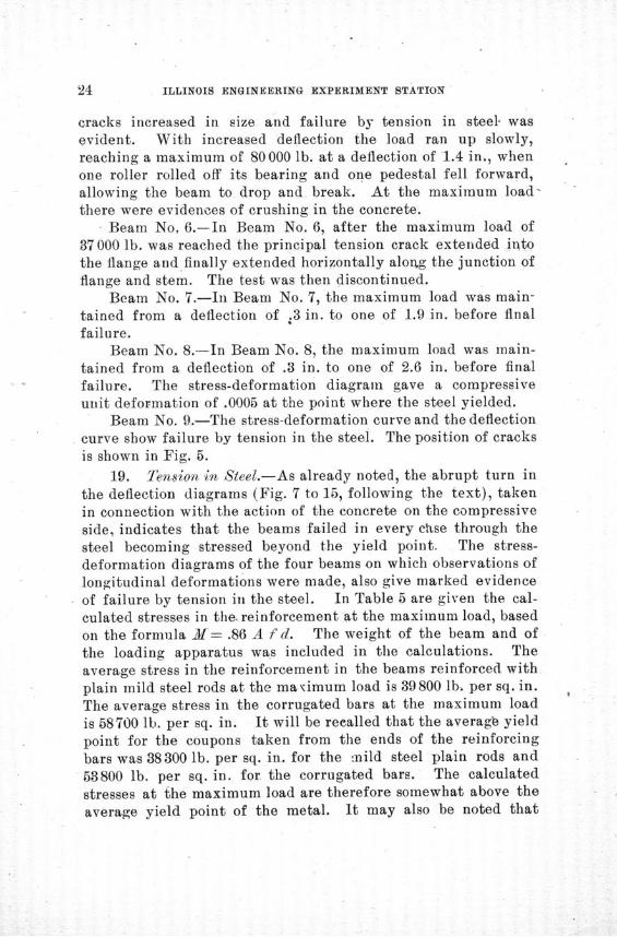
cracks increased in size and failure by tension in steel- wasevident. With increased deflection the load ran up slowly,reaching a maximum of 80000 lb. at a deflection of 1.4 in., whenone roller rolled off its bearing and one pedestal fell forward,allowing the beam to drop and break. At the maximum load-there were evidences of crushing in the concrete.
Beam No., 6.-In Beam No. 6, after the maximum load of37000 lb. was reached the principal tension crack extended intothe flange and finally extended horizontally along the junction offlange and stem. The test was then discontinued.
Beam No. 7.-In Beam No. 7, the maximum load was main-tained from a deflection of .3 in. to one of 1.9 in. before finalfailure.
Beam No. 8.--In Beam No. 8, the maximum load was main-tained from a deflection of .3 in. to one of 2.6 in. before finalfailure. The stress-deformation diagram gave a compressiveunit deformation of .0005 at the point where the steel yielded.
Beam No. 9.-The stress-deformation curve and the deflectioncurve show failure by tension in the steel. The position of cracksis shown in Fig. 5.
19. Tension in Steel.-As already noted, the abrupt turn inthe deflection diagrams (Fig. 7 to 15, following the text), takenin connection with the action of the concrete on the compressiveside, indicates that the beams failed in every chse through thesteel becoming stressed beyond the yield point. The stress-deformation diagrams of the four beams on which observations oflongitudinal deformations were made, also give marked evidenceof failure by tension in the steel. In Table 5 are given the cal-culated stresses in the, reinforcement at the maximum load, basedon the formula M=- .86 A f d. The weight of the beam and ofthe loading apparatus was included in the calculations. Theaverage stress in the reinforcement in the beams reinforced withplain mild steel rods at the ma'imum load is 39800 lb. per sq. in.The average stress in the corrugated bars at the maximum loadis 58700 lb. per sq. in. It will be recalled that the average yieldpoint for the coupons taken from the ends of the reinforcingbars was 38300 lb. per sq. in. for the mild steel plain rods and583800 lb. per sq. in. for the corrugated bars. The calculatedstresses at the maximum load are therefore somewhat above the
average yield point of the metal. It may also be noted that
TALBOT-TESTS OF REINFORCED CONCRETE T-BEAMS
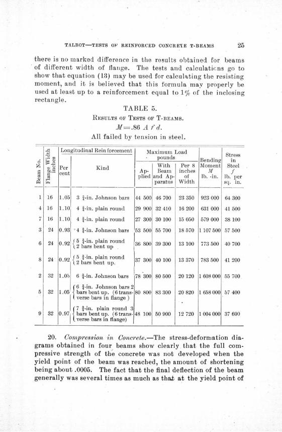
there is no marked difference in the results obtained for beamsof different width of flange. The tests and calculaticns go toshow that equation (13) may be used for calculating the resistingmoment, and it is believed that this formula may properly beused at least up to a reinforcement equal to 1% of the inclosingrectangle.
TABLE 5.
RESULTS OF TESTS OF T-BEAMS.
-M=.86 A fd.
All failed by tension in steel.
Longitudinal Rein forcement
Per Kindcent
1.05 3 f-in. Johnson bars
1.10 4 f-in. plain round
1.10 4 f-in. plain round
0.93 4 f-in. Johnson bars
0.92 5 i-in. plain round19 2 bars bent up
0.92 5 a-in. plain roundS9 2 bars bent up.
1.05 6 1-in. Johnson bars
f6 f-in. Johnson bars 21.05 bars bent up. (6trans-
verse bars in flange )
(7 f-in. plain round 30.971 bars bent up. (6trans-
( verse bars in flange)
Maximum Loadpounds
SWithAp- Beam14 A d AA
44 500
29 900
27 300
5O 5CA
36 800
37 300
78 300
80 800
48 100
ant p-paratus
46 700
32 410
30 100
55 700
39 300
40 100
80 500
83 300
50 900
Per 8inches
ofWidth
23 350
16 200
15 050
18 570
13 100
13 370
20 120
20 820
12 720
20. Compression in Concrete.-The stress-deformation dia-grams obtained in four beams show clearly that the full com-pressive strength of the concrete was not developed when theyield point of the beam was reached, the amount of shorteningbeing about .0005. The fact that the final deflection of the beamgenerally was several times as much as that at the yield point of
BendingMoment
M3lb. -in.
923 000
631 000
579 000
1107 500
773 500
783 500
608 000
1 658 000
1 004 000
Stressin
Steelf
lb. persq. in.
64 300
41 500
38 100
57 500
40 700
41 200
55 700
57 400
37 600
i.%• •71Jll
I
ILLINOIS ENGINEERING EXPERIMENT STATION
the beam shows that with the stretch of the steel beyond theyield point the neutral axis must have risen very much beforefinal or ultimate failure by crushing of the concrete occurred,and this corroborates the preceding statement. The results bearout the assertion that 'beams with 1% reinforcement will haveonly a part of the compressive strength of the concrete devel-oped, even when steel of 54000 lb. per sq. in. yield point is used.As in T-beams having a width of flange equal to four times thethickness of the stem a 1% reinforcement (4% of the stem area)is very large, it does not seem that the compressive strength ofthe concrete in the upper fiber may be expected to be a con-trolling element in floor construction of this kind.
21. Web Stresses.-Rectangular beams which do not havemetallic web reinforcement and in which the longitudinal barsare laid horizontally may be expected (for concrete of this qual-ity) to fail by diagonal tension when the calculated verticalshearing unit stresses reach, say, 120 lb. per eq. in., provided, ofcohrse, the amount of reinforcement and relation of depth tolength of span are not such that failure by tension or compressionwill occur before this amount of stress is developed. This is onthe assumption that the method of calculation given on page 10is applicable to T-beams so reinforced. For the T-beams tested,no matter what the width of flange, the load which wouldproduce failure by diagonal tension in the concrete calculated inthis way would be 17000 lb. As all beams failed by tension inthe steel and as the loads ran as high as 80000 lb. it is apparentthat the metallic web reinforcement was efficient and adequate.
The conditions of testing were not favorable for determiningthe time of appearance of the first diagonal cracks (the minutecracks which appear in the outer third of the span length andwhich in beams without metallic web reinforcement presageearly and sudden failure), and in some cases these may haveappeared before their presence was noted. However, the loadat which their existence was observed is given in Table 6. InBeam No. 7 the load for the first visible crack, 18000 lb., gives byequation (18) a value of the vertical shearing unit stress of 147 lb.per sq. in., not much above that at which a beam withoutmetallic web reinforcement would fail. The general averagetime of observation of the first visible diagonal crack correspondedto a value of about 180.1b. per sq. in. This higher value of v may
TALBOT-TESTS OF REINFORCED CONCRETE T-BEAMS
be an indication that the stiffness of the stirrups holds back thegrowth of cracks of the size at which they become visible oreven that the stirrups act with the concrete in taking thesesecondary stresses up to the load where the cracks becomevisible, or else that the method of calculation gives too highresults.
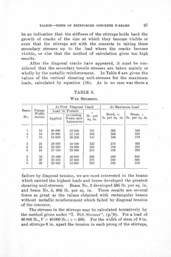
After the diagonal cracks have appeared, it must be con-sidered that the secondary tensile stresses are taken mainly orwholly by the metallic reinforcement. In Table 6 are given thevalues of the vertical shearing unit-stresses for the maximumloads, calculated by equation (18). As in no case was there a
TABLE 6.
WEB STRESSES.
At First Diagonal CrackLoad in rounds
Applied
20 00029 90018 000
28 00020 00027 000
36 00035 00032 000
in cludingBeam andApparatus
22 20032 10020 200
30 5002250029500
3880037 80034 800
Vlb. persq. in.
161234147
222164214
282275253
At Maximum Load
Bond, ulb. per sq. in.
302200186
270194198
260269180
Shear, vlb. per sq. in.
340236219
405286292
585605370
failure by diagonal tension, we are most interested in the beamswhich carried the highest loads and hence developed the greatestshearing unit-stresses. Beam No. 2 developed 585 lb. per sq. in.and beam No. 5, 605 lb. per sq. in. These results are severaltimes as great as the values obtained with rectangular beamswithout metallic reinforcement which failed by diagonal tensionof the concrete.
The stresses in the stirrups may be calculated tentatively bythe method given under "7. Web Stresses", (p.'9). For a load of80 000 l'b., V= 40000 lb.; v = 580. For the width of stem of 8 in.and stirrups 6 in. apart the tension in each prong of the stirrups,
Beam
No.
147
368
259
FlangeWidthinches
161616
242424
323232
ILLINOIS ENGINEERING EXPERIMENT STATION
calculated in this way, will be 13900 lb., equivalent to 55500 lb.per sq. in. The bond developed is also very high.
In the foregoing discussion the horizontal and vertical shear-ing stresses have been used as a means of comparing resistancesto diagonal stresses. Viewed by themselves, they are alsointeresting. 600 lb. per sq. in. is evidently well below the actualshearing resistance of concrete, but it is considerably above thevalues given as the ultimate shearing strength of concrete bythose who hold that shearing strength is but little more than thetensile strength of concrete.
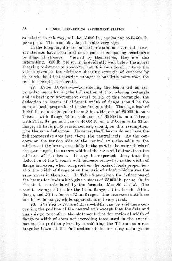
22. Beam Deflection.-Considering the beams all as rec-tangular beams having the full section of the inclosing rectangleand as having reinforcement equal to 1% of this rectangle, thedeflection in beams of different width of flange should be thesame at loads proportional to the flange width. That is, a load of10 000 lb. on a rectangular beam 8 in. wide, one of 20 000 lb. on aT-beam with flange 16 in. wide, one of 30000 lb. on a T-beamwith 24-in. flange, and one of 40000 lb. on a T-beam with 32-in.flange, all having 1% reinforcement, should, on this assumption,give the same deflection. However, the T-beams do not have thefull compressive area just above the neutral axis. As the con-crete on the tension side of the neutral axis also adds to thestiffness of the beam, especially in the part in the outer thirds ofthe span length, the narrow width of the stem will detract from thestiffness of the beam. It may be expected, then, that thedeflection of the T-beams will increase somewhat as the width offlange increases, when compared on the basis of loads proportion-al to the width of flange or on the bEsis of a load which gives thesame stress in the steel. In Table 7 are given the deflections ofthe beams for loads which give a stress of 35000 lb. per sq. in. inthe steel, as calculated by the formula, M= .86 A f d. Theresults average .27 in. for the 16-in. flange, .27 in. for the .24-in.flange, and .32 in. for the 32-in. flange. The decrease in stiffnessfor the wide flange, whlile apparent, is not very great.
23. Position of Neutral Axis.-Little can be said here con-cerning the position of the neutral axis except that the data andanalysis go to confirm the statement that for ratios of width offlange to width of stem not exceeding those used in the experi-ments, the position given by considering the T-beam as a rec-tangular beam of the full section of the inclosing rectangle is

TALBOT-TESTS OF REINFORCED CONCRETE T-BEAMS
sufficiently close for purposes of ordinary calculation. The stress-deformation diagrams for the beams on which observations weremade, so far as these results may be used, also corroborate thisview. As the compressive stresses in T-beams will generally below, the error in any use of the assumed inclosing rectangle likelyto be made will be small enough to be neglected, especially if we
TABLE 7.
DEFLECTIONS FOR A STRESS OF 35 000 LB. PER SQ. IN. IN THE STEEL.
M =.86 A f d.
Beam FlangeNo. Width
No. inches
1 164 167 16
Av.
3 246 248 24
Av.
2 325 329 32
Av. I
Per centReinforce-
ment
1.051.101.10
0.930.920.92
1.051.050.97
AppliedLoad Deflection
pounds inches
25200 0.2426500 0.2526500 0.31
0.27
33600 0.2533200 0.2733200 0.28
0.27
50500 0.3150500 0.3146700 0.34
0.32
limit the use to the condition that the flange shall extend two-thirds of the distance to the neutral axis.
24. Applicability of Results.-The tests are not numerousenough or sufficiently diversified to show that the results aregenerally applicable to beam construction. It seems clear, how-ever, from the general behavior of these beams that for calcula-tions on strength the T-section may be considered to be theequivalent of rectangular beams of the size of the inclosing rec-tangle for widths of flange equal at least to four times the widthof stem. It seems probable that this relation may be applicableto even greater widths of flange. However, the actual valueof this limit cannot be of great practical importance, since agreater width would not materially change the value of the cal-culated resisting moment (considering it based upon tensilestrength of steel and moment arm measured to center of com-pressive stress), and since the amount of steel will at any rate
ILLINOIS ENGINEERING EXPERIMENT STATION
be limited by the space in the stem and by practical considera-tions in placing and bedding it to an amount which will keep themaximum compressive stress within a reasonable limit.
The method of calculating the tension in the stirrups is usedtentatively and is not regarded as a final method for use. It isprobable that experiments will show that a different method ofcalculation should be adopted. The efficacy of stirrups of thiskind is well brought out, but at the same time, it should be notedthat the size, spacing, and bonding of the web reinforcement areof larger capacity than is usually given. The fact that all thebeams, and especially the wide beams, escaped failure by diagonaltension is of especial importance.
Nothing in the observed phenomena of the tests indicatesthat there was an appreciable distortion from a plane crosssection even in the flanges of the beam. The tearing of the flangein one beam was evidently due to unequal bending and seems notto be traceable to shear or to variations from.a plane cross section.
25. Summary.-The following summary of the discussion isgiven:
1. Beams of flange width of two, three, and four times thewidth of stem or web and reinforced in each case with steel equalto 1% of the inclosing rectangle exhibited in a common way thecharacteristics of rectangular beams, and the critical failure inevery case came through the longitudinal reinforcement becom-ing stressed beyond its yield point.
2. The full compressive strength of the concrete at the mostremote fiber was not developed at the yield point of the beam,even in the beams which were reinforced with steel of 54000 lb.per sq. in. yield point.
3. The beams with the wide flanges were deflected some-what more than the narrower beams, as may be expected fromthe lack of full width of concrete on both the compression andthe tension sides of the neutral axis, the deficiency affecting thestiffness of the beam but having little effect upon its strength atuoints of maximum bending moment.
4. The vertical stirrups used proved to be very effectiveweb reinforcement. The diagonal tension cracks appeared at orabove the loads at which failure by diagonal tension may beexpected in beams without web reinforcement. A high resistance
TALBOT-TESTS OF REINFORCED CONCRETE T-BEAMS
to diagonal tensile stresses was developed, as measured by thecalculated maximum vertical shearing unit-stress, which in onebeam was 605 lb. per sq. in. Since no beam failed by diagonaltension, the limit of strength of the web reinforcement was notdetermined.
5. The observed phenomena of the tests give no indicationof distortion from a plane cross section and there was no indica-
.tion that the thin flange was an element of weakness. The tear-ing of the flange of one beam after the -maximum load wasreached was due to causes which would not exist in a floor systemas usually constructed. It seems clear that the limit of usefulwidth of flange was not reached in the beams tested.
6. The maximum strength of T-beams to resist horizontaltension and compression (flange stresses) may well be calculatedby using the ordinary methods and formulas in use for rectangulazbeams and considering the inclosing rectangle of the T-beam tobe the equivalent rectangular beam. This approximation is atleast applicable for reinforcement not exceeding 1% of the inclos-ing rectangle. It gives little error when the thickness of flangeis at least one quarter of the depth of beam and the width offlange not more than four times the width of stem, and may beused-for an even greater range without great error. The in-clusion of a greater width of flange than four times the width ofstem would not materially change the calculated strength of thebeam, since the amount of steel which may be put into the stemis usually limited by considerations which of themselves will holdthe compressive stresses within proper limits, and since themoment arm of the horizontal couple will not change much withan increase in width of flange. The web stresses, which here arevery important, will differ from those found for rectangularbeams, and for T-heams the actual width of stem must be used inthe calculations for vertical shear and diagonal tension.

ILLINOIS ENGINEERING EXPERIMENT STATION
i l . . . . . . . . .I' l . .I1l l1
-- WeI j
ili iiIM ill")
It I 1 1 1 1I r 1 1 1 1 1 1 1 1 1 1I I ' I I I I E l I I I I I I I I
I I I i - l I I I I . . I I I . 1 i
d 1 I I I 1 1 1 1
i i i i i i iI II I I I I I III
I- IT I - -
tF -:LLLLLIHHIV1liiiii lull
F/8- . 9
7-£P4A'A'/ 7
/ff-/w. ^t.di#vee
DEIPL C7T/0/V /A/V IAI/CHS
Q
2) Z^
IQ
Moa~
S F
F 6 7L 7-BP•7/f A• J
% I
'I'lll'
31J660
N
ezIIt-iN"I
Q.
111111 I
8
T-B~AAf A'."4
/6-,,v Pr ~4'VG~
Jv
1 1 3 - 1 1 1 1 1 1
n-r-tSt
tuSi i l i i i i I
m--
I I I ..........1I I ý TI I T I *M - - - - ý1
IIIlllll
S I
1
9t
I
I
OF REINFORCED CONCRETE T-BEAMS
I I .I -I I lI i i . i i i i ii 1 " 11 i i :
,.J0Wr
'4
F/6./O
7-d•BL N,• -, 6'2-.-/,. Fzdwc/vG
. ... . . . ... •. .. .. . . . . ..
lea.
I I I IJ. I i IA I 1
1D 1.127- 16-141-f/V2 IR4-/At rkxA'Ge
cap""rm'r 9a'
L)FL C 7 70/bO /11 /INCH/AJ
-,-2' I- I
'2 .I iiiIi'
N
* /1.//
7- Be," IVP
ý14-I rILAWEs
lomm" oowada PI
. . I .. . . I . . .. . . . . . . . . . . . .;
1 1 1 1 1 1 1 1 dmA-d6Q44o4 " i I 1 1 1
. .. . . . . ... . . .. . . .'. My""
T-T Fl~ffi ,_ýl l
_+--
I 1 1 1 1 I I 1 1 1 1 i l l i1
TALBOT-TESTS
| •,€ •'/4¥ ,4"15-V/¥M •l,•lr•
•J
•T
ILLINOIS ENGINEERING EXPERIMENT STATION
- T TTr"rY1
m
I1 - II II I I I I
//6. /3
TpBf4/AA /V0 9f
JA/d/AAid''0VSE,2
i 11 1 U 07 l'' i t
I I I T~r~~r1r1F111TmIII 11111
I Ill I I I I I I I I I I I I I I
I l l .III"
III 111111111 IIII*I I
:11.1I II l l i l i a l i l I I
S I I I I .I I I I I I . .r .I
Z. %996f6 *444--4
I?! I I I I I I I IIIII..i,,.,,,,
-IiI I I 1 1 I J1 il l
':
jill liii j II 11111 I I I I I
I I I I I I I I *IIIIIII~, I I I I I1111111
II I I IIIIIIIi,.,..,, I I1-A -11 -I 1 1
ld ra8/Y /vZ
4"/A- 3-//. FZ dI6£
_~- Cweiu~re 8A AF
f~,'$. /5
r-8t,4A',v2 5JZV# A2 dA'c~
2'~'.pt's#rz'o &~'j
DOFL PC LCTION IV //VCH- S
IIII1I11
t2ii Vrn
s.J
ri
^
1 ' tl J
1 1 1
I I f
•LlJJlI l l i l l l m - I I
s i m i d
Illi l
4(/ffff
ni l I. . . . . . . . .
Im I I I 1 5 I I
M
I
y /000i
TALBOT-TESTS OF REINFORCED CONCRETE T-BEAMS
PUBLICATIONS OF THE ENGINEERING EXPERIMENT STATION
Bulletin No. 1. Tests of Reinforced Concrete Beams, byArthur N. Talbot. 1904.
Circular No. 1. High-Speed Tool Steels, by L. P. Brecken-ridge. 1905.
Bulletin No. 2. Tests of High-Speed Tool Steels on CastIron, by L. P. Breckenridge and Henry B. Dirks. 1905.
Circular No. 2. Drainage of Earth Roads, by Ira 0. Baker.1906.
Bulletin No. 3. The Engineering Experiment Station of theUniversity of Illinois, by L. P. Breckenridge. 1906.
Bulletin No. 4. Tests of Reinforced Concrete Beams, Seriesof 1905, by Arthur N. Talbot. 1906.
Bulletin No. 5. Resistance of Tubes to Collapse, by AlbertP. Carman. 1906.
Bulletin No. 6. Holding Power of Railroad Spikes, by RoyI. Webber. 1906.
Bulletin No. 7. Fuel Tests with Illinois Coals, by L. P.Breckenridge, S. W. Parr and Henry B. Dirks. 1906.
Bulletin No. 8. Tests of Concrete: I. Shear; II. Bond, byArthur N. Talbot. 1906.
Bulletin No. 9. An Extension of the Dewey Decimal Systemof Classification Applied to Engineering Industries, by L. P.Breckenridge and G. A. Goodenough. 1906.
Bulletin No. 10. Tests of Plain and Reinforced ConcreteColumns, Series of 1906, by Arthur N. Talbot. 1907.
Bulletin No. 11. The Effect of Scale on the Transmission ofHeat through Locomotive Boiler Tubes, by Edward C. Schmidtand John M. Snodgrass. 1907.
Bulletin No. 12. Tests of Reinforced Concrete T-beams,Series of 1906, by Arthur N. Talbot. 1907.

~?w 224, 4,
I' ~ -i4y~ 2~-
A7
A
'A
hA
A
4/~ '~,
<I
YUNIVERSITY op ILLINOIS
THE UNIVERSITY INCLUDES THECOLLEGE OF LITERAI URE AND ARTS (Ancient and Modern
'Languags and Literatures, Philosophical and Political Sci-ence Groups of Studies, kcononics, Cpmmerce and Industry)
COLLEGE OF ENGINEERING (Unexcelled library; spaciousbuildings; well-equiipped laboratories and shops. Graduateand Undergraduate courses in Architecture; ArchitecturalEngineering; Architectural Decoration; Civil Engineering;Mun'icipal and Sanitary Engineering; Electrical Engineering;Mechanical Engineeing; Railway Engineering).
COLLEGE OF SCIENCE (Astronomy, Botany, Chewistry, Geology,Mathematics, Physics, Physiology, Zo6logy).
COLLEGE OF AGRICULTURE (Animial Husbandry, Agronomy,Dairy Husbandry, Horticulture, Veterinary, Science, House-old Science),.
COLLEGE- OF LAW (Three years' course).COLiLEGE OF MEDICINE (College of Physicians and Surgeons,
Chicago). (Four years' course).COLLEGE OF DENTISTRY (Chicago). (Three years' course).SCHOOLS-MfUSIC (Voice, Piano. Violin). LIBRARY SCINCE.
4'~ ~
~A ~ ~
~"
1A ~
VA
4,
* 44"
A'A
44 v
'4, VV V
4 V ~VV~

'-,7- )'',,,.
^.4 4 •"\ ^''
A
'.4.4 .4 -
14,4 ' '<4
.4.
.4 4,
S , ".4%
4 4'.4
,44
.4 7,,
* A,
t4
..
~< 44'
I
~.44 4~4'44 &
'44
44 .4
-+A /
4%
4 4
44.4
.7<
4 4'
'4^ . ^^ "lf
)' •V 7
4,^
'4 .44 4
'^
i• i̧•,• •!•i!•ii
• •i•ii•ii,•b••