testo easyheat english
TRANSCRIPT

Instruction manual en
testo easyheatConfiguration and Analysis software
General InformationThis documentation includes important information about the features and application ofthe product. Please read this documentation through carefully and familiarise yourselfwith the operation of the product before putting it to use. Keep this document to handso that you can refer to it when necessary.
This documentation describes the software with the program language English -GGB.
The range of functions of the software depends on the country version of themeasuring instrument connected and on the number and kind of instrument types forwhich the software has been enabled via licence key. The descriptions in thisdocument apply to the complete enabling of all instrument types.
SymbolsSymbol Meaning
Identifies particularly important information.
Text Text appears on the instrument display or PC monitorPosition cursor over the whole element and click with the left mouse button.*Position cursor over the whole element and click with the right mouse button.*
* Data refers to standard mouse configuration (left button: selects, right button: context menu)
TTrraaddeemmaarrkkssMicrosoft and Windows are registered trademarks of the Microsoft Corporation in the USA and/or other countries.Intel and Pentium are registered trademarks of the Intel Corporation in the USA and/or other countries.Other trademarks or product names are the property of the respective owner.
General Information2
ContentGeneral Information ..............................................................................2
Content ..........................................................................................................3
A. Intended Purpose ................................................................................6
B. Using software ......................................................................................7B.1 System requirements ....................................................................7B.2 Installing software ..........................................................................7B.3 Starting the software ......................................................................8B.4 Setting up the connection ..............................................................8
C. Operation ..............................................................................................9
D. Application example ..........................................................................11
E. Ribbon bar ..........................................................................................13E.1 Testo Logo ..................................................................................13
E.1.1 Enhance licence ......................................................................13E.2 General ........................................................................................13
E.2.1 Previous module ......................................................................13E.2.2 Initial page ..............................................................................14E.2.3 Exit ..........................................................................................14
E.3 Customer ....................................................................................14E.3.1 Search customer ....................................................................14
E.3.1.1 List of customers ..............................................................................15E.3.2 Show customer data ................................................................16
E.3.2.1 Address ............................................................................................16E.3.2.2 List of locations ..................................................................................17
E.3.3 Change customer data ............................................................17E.3.4 Insert new customer ................................................................18E.3.5 Import customer data ..............................................................18
E.4 Locations ....................................................................................19E.4.1 Show measure location data ....................................................20
E.4.1.2 Measurements ..................................................................................20E.4.1.3 Task ..................................................................................................21
E.4.2 Change measure location data ................................................21E.4.3 Insert new location ..................................................................22E.4.4 Print barcodes ........................................................................22
Content 3

E.5 Measurements ............................................................................23E.5.1 Search measurement ..............................................................23E.5.2 Display measurement data ......................................................24
E.5.2.1 Information ..............................................................................................24E.5.2.2 Graphics ..................................................................................................25E.5.2.3 Measure values ........................................................................................25
E.6 Jobs ............................................................................................26E.6.1 Search job ..............................................................................26E.6.2 Show job details ......................................................................27E.6.3 New job ..................................................................................27
E.7 Employee ....................................................................................28E.7.1 All employees ..........................................................................28E.7.2 Change employee ....................................................................29E.7.3 New employee ........................................................................29E.7.4 Job list ....................................................................................29
E.8 testo 312-4 ..................................................................................30E.8.1 Download measurement data ................................................30E.8.2 Online measurement ................................................................31E.8.3 Configure testo 312-4 ............................................................32
E.8.3.1 Serial connection to testo 312-4 ........................................................32E.8.3.2 Instrument ..........................................................................................33E.8.3.3 Date / Time ........................................................................................33E.8.3.4 Print text ..........................................................................................33E.8.3.5 Logger programme ..........................................................................33E.8.3.6 Memory ............................................................................................33
E.9 testo 314 ....................................................................................34E.9.1 Transmit measure locations ......................................................34
E.9.1.1 Measure locations on PC ..................................................................35E.9.1.2 Measure locations on instrument ........................................................35
E.9.2 Download measurement data ................................................36E.9.3 Configure testo 314 ................................................................36
E.9.3.1 Serial communication ........................................................................37E.9.3.2 Clock ................................................................................................37E.9.3.3 Print text ..........................................................................................37
Content4
E.10 testo 330 ....................................................................................37E.10.1 Transmit measure locations ......................................................38
E.10.1.1 Measure locations on PC ........................................................................38E.10.1.2 Measure locations on instrument ............................................................39
E.10.2 Download measurement data ................................................39E.10.3 Online measurement ................................................................40E.10.4 Configure testo 330 ................................................................41
E.10.4.1 Instrument ..............................................................................................41E.10.4.2 Date/Time ..............................................................................................41E.10.4.3 Display edit ............................................................................................42E.10.4.4 Sensor settings ......................................................................................42E.10.4.5 Print text ................................................................................................42E.10.4.6 Memory ..................................................................................................42
E.11 Settings ......................................................................................43E.11.1 Synchronise Pocket PC ..........................................................43
E.11.1.1 Synchronisation ......................................................................................43E.11.1.2 Configuration ..........................................................................................43
E.11.2 Install easyheat.mobile ............................................................44E.11.3 Report design ..........................................................................44
E.11.3.1 Field, Font, Border, Page ........................................................................45E.11.3.2 Editor ......................................................................................................46E.11.3.3 Preview ..................................................................................................46
E.11.4 Configuration ..........................................................................46E.11.4.1 Instruments ............................................................................................47E.11.4.2 Programme ............................................................................................47E.11.4.3 Customer data ........................................................................................47E.11.4.4 Own data ................................................................................................47E.11.4.5 Color scheme ........................................................................................47E.11.4.6 Backup ..................................................................................................47
E.11.5 Information ..............................................................................47E.12 Database ....................................................................................48
E.12.1 Full backup ..............................................................................48E.12.2 Incremental backup ................................................................48E.12.3 Restore database ....................................................................48E.12.4 Repair and compact ................................................................48
E.11 ? (Info) ........................................................................................49
F. Questions and Answers ......................................................................49
Content 5
A. Intended Purpose The testo easyheat configuration and analysis software adds many useful functions tothe testo 312-4, testo 314 and testo 330 measuring instruments:- Instrument configuration via software.- Manages customer, system and measurement data. - Data import from and data export to the measuring instrument. - Sets up, saves and prints measurement protocols from imported data.
A. Intended purpose6
B. Using software
B.1 System requirementsOperating system
Microsoft® Windows® 2000 (from Service Pack 4), Windows® XP (from Service Pack 2)or Windows® Vista
Processor (min.)
Intel® Pentium® III, 800MHz
RAM (mind.)
128MB with Windows® 2000 and Windows® XP
1 GB with Windows® Vista
Other hardware (min.)
CD-ROM drive for installation, mouse, USB 1.1 interface
Monitor resolution (min.):
1024 x 768 pixels
Hard drive (min.)
150MB free memory
B.2 Installing softwareTo install the USB driver, please read the separate documentation included with theUSB driver CD.
Administrator rights are required in Windows® 2000, Windows® XP and Windows®
Vista to install the program.
Once installed, input of a licence key is required. Without this input, the software willonly run as a demo version with a limited range of functions (time limit of 30 days). When the software is first started, a window automatically appears for you to enterthe licence key.
B. Using software 7
1 Insert CD.
If the installation program does not start automatically:
Open Windows Explorer and start the Setup.exe file ( click twice).
2 Follow the instructions in the installation program.
B.3 Starting the software( ) Programs Testo testo easyheat configuration and analysis software ( ).
- The program is opened. The program language corresponds to the operating systemlanguage.
- When the software is first started, a window appears for you to enter the licence key.
Enter licence key (found on the CD packaging)) OK ( ).The range of functions of the software depends on the country version of theanalyser connected. and on the number and kind of instrument types for which thesoftware has been enabled via licence key. To enter additional licence keys, refer to Enhance licence, p. 13.
B.4 Setting up the connectiontesto 314
To connect testo 314 to a PC the “connection cable PC/ instrument 0409 0178” isrequired.
1 Connect cable to a serial connection socket in the PC.
2 Connect cable to RS232 socket in measuring instrument.
3 Switch on instrument ( ).
testo 330
To connect testo 330 to a PC the “connection cable PC/instrument 0449 0047” isrequired.
1 Install the USB driver. To do this, select Install TTesto UUSB DDriver in the directory USBDriver on the CD.
2 Connect connection cable to a USB socket in the PC.
3 Connect connection cable to a USB socket in the analyser.
4 Switch on analyser ( ).
B. Using software8
testo 312-4
The “Connection cable 0409 0178 PC/instrument is required for the connection of thetesto 312-4 to a PC.
1 Connect connection cable to a serial connection socket of a PC.
2 Connect connection cable to the RS 232 socket of the instrument.
3 Switch instrument on ( ).
testo 330 only
The analyser switches to the Slave Mode during data transfer; the analyser operatingbuttons are disabled in this mode. Once data is no longer being transferred the SlaveMode is stopped and the analyser can be controlled via the control buttons, asnormal.
C. Operation
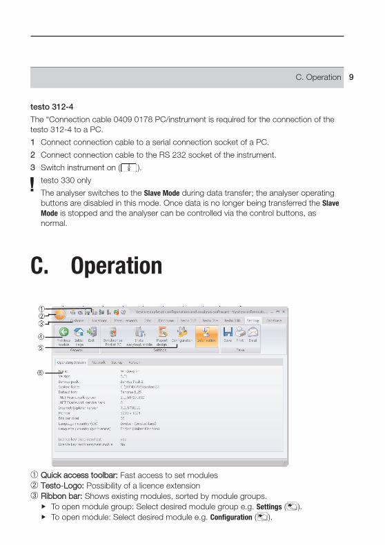
Quick aaccess ttoolbar: Fast access to set modules Testo-LLogo: Possibility of a licence extensionRibbon bbar: Shows existing modules, sorted by module groups.
To open module group: Select desired module group e.g. Settings ( ).To open module: Select desired module e.g. Configuration ( ).
C. Operation 9
The modules can also be opened with the quick access toolbar. The menus have thesame names as the corresponding module groups.
Some of the modules can only be opened if data was stored or specific data wasselected in advance in another module.
Ribbon ggroup GGeneral: Several important functions can be called up by clicking onthe symbolRibbon ggroup ffunction: Shows the active module. The module window is the workarea in which all entries are made.
If a module is not activated, the homepage containing the modules required mostfrequently (favourites) appear enabling direct access.
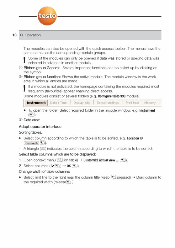
Some modules consist of several folders (e.g. Configure testo 330 module):
To open the folder: Select required folder in the module window, e.g. Instrument( ).
Data aarea:
Adapt operator interface
Sorting ttables:
Select column according to which the table is to be sorted, e.g. Location ID( ).
- A triangle ( ) indicates the column according to which the table is to be sorted.
Select ttable ccolumns wwhich aare tto bbe ddisplayed:
1 Open context menu ( on table) Customize actual view ... ( ).
2 Select columns ( ) OK ( ).
Change wwidth oof ttable ccolumns:
Select limit line to the right near the column title (keep pressed) Drag column tothe required width (release ).
C. Operation10

D. Application exampleThe most important steps required for a typical application of the software is explainedin this Chapter using an example.
A detailed description of all software functions can be found at Ribbon bar, p. 13.
Configuring software
1 Settings ( ) Configuration ( ).
2 Own data ( ) Enter/change address data.
3 Customer data ( ) Activate functions required.
4 Backup ( ) Undertake settings.
5 Taking on changes: Save ( ).
Configuring the analyser (testo 314, testo 330)
1 testo 314 ( ) Configure testo 314 ( ) and testo 330 ( ) Configure testo 330 ( ).
2 Print text ( ) Own address data ( ) Apply ( ).
Configuring the analyser (testo 312-4)
1 testo 312-4 ( ) Configure testo 312-4 ( )
2 Print text ( ) Print line ( ) Save ( ).
Setting up new customers
1 Customer ( ) Insert new customer ( ).
2 Enter new customers in the corresponding boxes Save ( ).
Setting up a new location
1 Locations ( ) Insert new location ( ).
2 Enter new location in the corresponding boxes in the folders Location, Installation,Boiler, Furnace Save ( ).
Transmitting location(s) to the instrument
1 testo 314 ( ) Transmit measure locations ( ) and testo 330 ( ) Transmit measure locations ( ).
2 Select location(s) in the Measure locations on PC folder ( ) Transmit ( ).
D. Application example 11
Carrying out measurements
To activate location, carry out measurement and save reading: see Instruction manualon testo 314, testo 312-4 or testo 330.
Reading in measurement data protocol(s) from the instrument
1 testo 314 ( ) Read measurement data ( ) and testo 330 ( ) Read measurement data ( ) andtesto 312-4 ( ) Read measurement data ( ).
2 Select measurement protocol(s) in folder Measurements in instrument ( ) Read( ).
Displaying and printing a measurement protocol
1 Measurements ( ) Search measurement ( ).
2 Select measurement protocol ( ) View ( ).
3 Print measurement protocol: Print ( ).
D. Application example12
E. Ribbon bar
E.1 Testo Logo
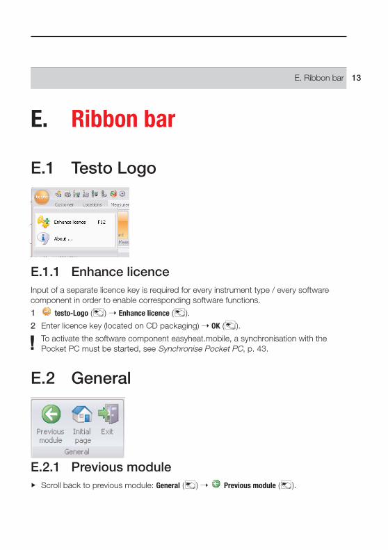
E.1.1 Enhance licenceInput of a separate licence key is required for every instrument type / every softwarecomponent in order to enable corresponding software functions.
1 testo-Logo ( ) Enhance licence ( ).
2 Enter licence key (located on CD packaging) OK ( ).
To activate the software component easyheat.mobile, a synchronisation with thePocket PC must be started, see Synchronise Pocket PC, p. 43.
E.2 General
E.2.1 Previous moduleScroll back to previous module: General ( ) Previous module ( ).
E. Ribbon bar 13
E.2.2 Initial pageOpen initial page: General ( ) Initial page ( ).
The initial page includes the modules used most frequently for direct access (favourites).
E.2.3 ExitEnd program: General ( ) Exit ( ).
- If you have not carried out data backup on the day, the Database backup window willopen offering you the following options:
· Complete backup: A complete backup is made of the database.· Save changes: Any changes made since the last backup will be saved.· Currently no backup: Program is ended without data backup being carried out.
Carrying out data backup: Select required option ( ) OK ( ) OK ( ).
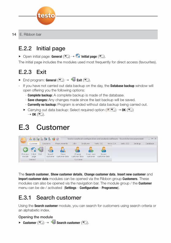
E.3 Customer
The Search customer, Show customer details, Change customer data, Insert new customer andImport customer data modules can be opened via the Ribbon group Customers. Thesemodules can also be opened via the navigation bar. The module group / the Customermenu can be de-/ activated (Settings - Configuration - Programme).
E.3.1 Search customerUsing the Search customer module, you can search for customers using search criteria oran alphabetic index.
Opening the module
Customer ( ) Search customer ( ).
E. Ribbon bar14

E.3.1.1 List of customersSelect desired search criterion (condition) for a field ( ).
- All customers whose entry in e.g. the field Name/Company begin with thecorresponding condition, are displayed.
- If you enter several search criteria (conditions) for a search, only those customerswho match these criteria will be found
Activating customers
If a customer is not activated, the Show customer data and Change customer datamodules cannot be opened.
Activating customers ( ).
- The selected customer is highlighted in color.
Displaying customer data
Activating customers ( ) Show costumer data ( ).
- The Show customer data module is opened, see Show customer data, p. 16.
Changing customer data
Activating customers ( ) Change costumer data ( ).
- The Change customer data module is opened, see Change customer data, p. 17.
Deleting customers
Activating customers ( ) Delete ( ) Yes ( ).
- The customer is deleted.
If a customer is deleted, all measurement sites and measurements of this customerare removed from the memory.
Setting up new customers
New ( ).
- The Insert new customer module is opened, see Insert new customer, p. 18.
E. Ribbon bar 15
E.3.2 Show customer dataThe address data and the customer’s saved systems can be shown with the Showcustomer data module.
Opening a module
The Show customer data module can only be opened if a customer has been activatedin the Search customer module, see Search customer, p. 14.
Customer ( ) Search customer ( ).
The Show customer data module is divided into two areas. The Address folder is located inthe upper area while the List of locations folder is located in the lower area.
E.3.2.1 Address
Changing address
Change ( ).
- The Change customer data module is opened, see Change customer data, p. 17.
Deleting customers
Delete ( ) Yes ( ).
- The customer is deleted.
Searching for customers
Search ( ).
- The Search customer module is opened, see Search customer, p. 14.
E. Ribbon bar16
E.3.2.2 List of locations
Activating location
If a location is not activated the Show measure location data and Change measure locationdata modules cannot be opened.
Activating a location ( ).
- The selected location is highlighted in color.
Displaying measurement location data
Select location ( ) Show measure location data ( ).
- The Show measure location data module is opened, see Show measure location data, p. 20.
Changing measurement location data
Activating location ( ) Change measure location data ( ).
- The Change measure location data module is opened, see Change measure locationdata, p. 21.
Deleting a location
Activating location ( ) Delete ( ) Yes ( ).
- The location is deleted.
If a measurement site is deleted, all measurements are deleted which were allocatedto this measurement site.
Setting up a new location
New ( ).
- The Insert new location module is opened, see Insert new location, p. 22.
E.3.3 Change customer dataExisting customer data can be changed with the Change customer data module.
Opening a module
The Change customer data module can only be opened if a customer was activated inthe Search customer module, see Search customer, p. 14.
Customer ( ) Change customer data ( ).
Changing data
A specific customer number is assigned to one customer when first set up. It cannotbe changed afterwards.
E. Ribbon bar 17

Enter changes to the customer data in the corresponding boxes Save ( ).
- The Show customer data module is open, see Show customer data, p. 16.
E.3.4 Insert new customerA new customer can be set up with the Insert new customer module.
Opening the module
Customer ( ) Insert new customer ( ).
Ensure that the customer number is allocated correctly, it cannot be changed at alater stage.
Enter new customer data in the corresponding boxes Save ( ).
- The Show customer data module is opened, see Show customer data, p. 16.
E.3.5 Import customer dataUsing the Import customer data module, existing customer data can be imported fromother applications.
Opening the module
Customer ( ) Import customer data ( ).
Importing data
Before importing customer data, it has to be changed to a supported import format:· Text file with separating character (comma, semicolon, Tabulator)· Microsoft® Access® database· Microsoft® Excel® worksheetStandard programs (such as Microsoft® Outlook®) usually support one of the namedformats.
1 Select import format ( ) - Locate ( ).
2 Select file to be imported.
When iimporting aan AAccess ddatabase yyou mmay bbe rrequired:
To enter User ID and Password.
3 Next > ( ).
When iimporting aan EExcel wworksheet yyou mmay bbe rrequired:
To select a worksheet ( ) Next >.
When iimporting aan AAccess ddatabase yyou mmay bbe rrequired:
To select a table ( ) Next >.
E. Ribbon bar18

Allocating import data
Once the data is read in, the data boxes have to be allocated. Only allocated data boxeswill take effect.
When iimporting ffrom aa ttext ffile, iit iis ppossible tthat tthe ffirst lline ddoes nnot iinclude aanyaddress ddata. IIf rrequired:
First line contains column name ( ).
1 Open list box ( ) - Select target data box ( ).
- The import data box is allocated to the target data box.
2 Repeat step 1 for all required data boxes.
If the Customer ID data box is empty for one customer, a customer number is assignedautomatically.If the Customer ID data box is available for a customer but the customer number isalready assigned in the configuration and analysis software the available data isreplaced by import data. If the Name/Company data box for a customer is empty, the customer data is notimported.
3 Apply ( ) OK ( ).
- The Search customer module is opened, see Search customer, p. 14.
E.4 Locations
The Show measure location data, Change measure location data, Insert new location and Printbarcodes modules can be opened via the Locations menu. You can also open thesemodules using the navigation bar.
E. Ribbon bar 19
E.4.1 Show measure location dataSystem data and the measurement data saved in a system can be displayed with theShow measure location data module.
Opening a module
With activated module group/menu Customer (Settings - Configuration - Programme): TheShow measure location data module can only be opened if a location was activated inthe, Show customer data module, see Show customer data, p. 16.
Locations ( ) Show measure location data ( ).
The Show measure location data module is divided into two areas. The Location, Owner,Installation, Boiler and Furnace folders are located in the upper area, in the lower area, theMeasurement values and Tasks folders. The Tasks folder is only available if the Jobmanagement module group/menu is activated (Settings - Configuration - Programme).
E.4.1.1 Location, Owner, Installation, Boiler, FurnaceChanging location data
Change ( ).
- The Change measure location data module is opened, see Change measure locationdata, p. 21.
Open Show customer data module
Show customer data ( ).
- The Show customer data module is opened, see Show customer data, p. 16.
E.4.1.2 Measurements
Activate measurement protocol
If a measurement protocol is not activated, the Display measurement data modulecannot be opened.
Activate the measurement protocol ( ).
- The selected measurement protocol is highlighted with color.
Displaying a measurement protocol
Activating the measurement protocol ( ) Display ( ).
- The Display measurement data module is opened, see Display measurement data, p. 24.
E. Ribbon bar20

Deleting a measurement protocol
Activate the measurement protocol ( ) Delete ( ) Yes ( ).
- The measurement protocol is deleted.
E.4.1.3 Task
New Job
New ( ).
- The New Job module is opened, see New Job, p. 27.
Delete job
Activate job ( ) Delete ( ) Yes ( ).
- The job is deleted.
E.4.2 Change measure location dataExisting location data can be changed using the Change measure location data module.
Opening the module
With activated Customer module group/menu (Settings - Configuration - Programme): TheChange measure location data module can only be opened if a location was selected inthe Show customer data module, see Show customer data, p. 16.
Locations ( ) Change measure location data ( ).
Changing data
The system number is determined and allocated when the location is first set up. Itcannot be changed at a later stage.
Enter changes to the location in the appropriate boxes Save ( ).
- The Show measure location data module is opened, see Show measure location data, on this page.
E. Ribbon bar 21

E.4.3 Insert new locationA new location can be set up with the Insert new location module.
Opening the module
Locations ( ) Insert new location ( ).
Ensure that the system number is assigned correctly, it cannot be changed at a laterstage.
Enter the data from the new location in the corresponding boxes in the Location,Installation, Boiler and Furnace folders Save ( ).
- The Show measure location data module is opened, see Show measure location data, p. 20 .
E.4.4 Print barcodesBarcode labels can be printed via the Print barcodes module. The system numbers storedin the barcode can be read in to the analyser using a barcode reader. In this way, thecorresponding location in the instrument is activated.
Opening a module
Locations ( ) Print barcodes ( ).
Printing barcode labels
1 Select locations for which a barcode label is to be printed ( ).
Options:
Select all locations: Select all ( ).
No location selected: Select none ( ).
2 Enter Company.
The company name is printed above the barcode.
3 Define Paper size and number of Columns and Lines ( or ).
For Testo labels (0554 0411): paper size DIN A4, 2 columns, 6 lines.
4 Set Copies per label ( ).
5 Select label at which printout is to begin ( on the label).
6 Start printout: Print ( ).
E. Ribbon bar22
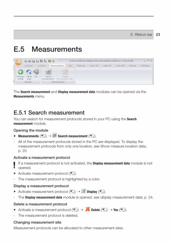
E.5 Measurements
The Search measurement and Display measurement data modules can be opened via theMeasurements menu.
E.5.1 Search measurementYou can search for measurement protocols stored in your PC using the Searchmeasurement module.
Opening the module
Measurements ( ) Search measurement ( ).
- All of the measurement protocols stored in the PC are displayed. To display themeasurement protocols from only one location, see Show measure location data, p. 20.
Activate a measurement protocol
If a measurement protocol is not activated, the Display measurement data module is notopened.
Activate measurement protocol ( ).
- The measurement protocol is highlighted by a color.
Display a measurement protocol
Activate measurement protocol ( ) Display ( ).
- The Display measurement data module is opened, see display measurement data, p. 24.
Delete a measurement protocol
Activate a measurement protocol ( ) Delete ( ) Yes ( ).
- The measurement protocol is deleted.
Changing measurement site
Measurement protocols can be allocated to other measurement sites.
E. Ribbon bar 23
1 Activate measurement protocol ( ) Change location ( ).
2 Activate the measurement site to which the measurement protocol is to be allocated( ) OK ( ).
- The measurement protocol is allocated to the selected measurement site.
Multiple measurement protocols can be merged into one measurement protocol.
1 Activate measurement protocols ( ); for multiple selections, hold down the [Ctrl]key.
2 Connect ( ).
3 Select location where the measurement protocol is to be saved OK ( ).
- The measurement protocols are merged into one protocol.
Exporting/importing measurement protocols
1 Activate measurement protocol ( ) Export ( ) or Import ( ).
2 Enter file name Save ( ) or select file Open ( ).
- The measurement protocol is imported or exported.
E.5.2 Display measurement dataMeasurement protocols can be displayed and processed via the Display measurement datamodule.
The Display measurement data module can only be opened if a measurement protocolwas selected in the Search measurement or Show measure location data modules, seeSearch measurement, p. 23 or Show measure location data, p. 20.
Open a module
Measurements ( ) Display measurement data ( ).
E.5.2.1 InformationInformation on the measurement protocol is shown in the Information folder.
Enter text in the Remark box.
Print measurement protocol
Print measurement protocol with information data and readings: Print ( ).
Display print preview
Display measurement protocol as a print preview: Preview ( ).
E. Ribbon bar24

E.5.2.2 GraphicsThe readings are shown in graphics form in the Graphics folder (maximum 16 channels).
The Graphics folder can only be opened for measurement protocols in testo 330 if anonline measurement is involved.
Changing features in graphics
1 Settings ( ).
2 Channel: Select measurement channels ( ), Legend: Enter channel name.
3 Save settings: OK ( ).
Print measurement protocol
Print measurement protocol with information data and readings: Print ( ).
Save graphics as a file
Save grapfic ( ) Enter file name ( / ) Enter file type ( / ) Save ( ).
E.5.2.3 Measure valuesThe readings in a table or list are shown in the Measure values folder.
Print measurement protocol
Print measurement protocol with information data and readings: Print ( ).
Display print preview
Display measurement protocol as a print preview: Preview ( ).
Export readings as an Excel file
Export Excel ( ).
Export readings into the PC’s clipboard
Clipboard ( ).
- The readings are exported as a file text, separated by tabs, into the PC’s clipboard.
E. Ribbon bar 25
E.6 Jobs
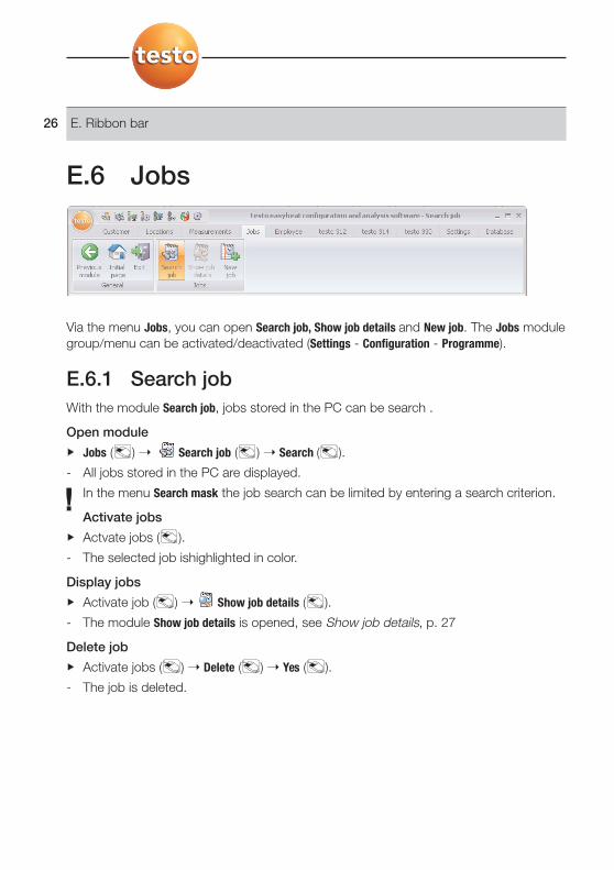
Via the menu Jobs, you can open Search job, Show job details and New job. The Jobs modulegroup/menu can be activated/deactivated (Settings - Configuration - Programme).
E.6.1 Search jobWith the module Search job, jobs stored in the PC can be search .
Open module
Jobs ( ) Search job ( ) Search ( ).
- All jobs stored in the PC are displayed.
In the menu Search mask the job search can be limited by entering a search criterion.
Activate jobs
Actvate jobs ( ).
- The selected job ishighlighted in color.
Display jobs
Activate job ( ) Show job details ( ).
- The module Show job details is opened, see Show job details, p. 27
Delete job
Activate jobs ( ) Delete ( ) Yes ( ).
- The job is deleted.
E. Ribbon bar26
E.6.2 Show job detailsMit dem Modul Show job details können Aufträge angezeigt und weiter verarbeitetwerden.
Das Modul Show job details kann nur geöffnet werden, wenn im Modul Search job einAuftrag markiert wurde, siehe Search job, on this side.
Modul öffnen
Jobs ( ) Show job details ( ).
E.6.3 New jobWith the New job module, a new employee job can be entered that is automaticallyassigned to the respective employee and appears in his or her job list.
Open the module
The New job module can only be opened if an employee was activated in the Allemployees module, see All employees, p. 28.
Jobs ( ) New job ( ).
Enter data
1 Select the date which should apply to the job ( ).
2 Enter job data in the corresponding fields Ready ( ).
E. Ribbon bar 27

E.7 Employee
Using the Employee menu, the All employees, Change employee, New employee, and Job listmodules can be opened.
E.7.1 All employeesAll entered employee data is displayed in the All Employees module and the employeewhose job list should be created/displayed can be activated.
Open the module
Employee ( ) All Employees ( ).
Activate employee
If no employee is activated, the Change employee and Job list modules cannot beopened.
Activate employee ( ).
- The selected employee is highlighted.
Display job list
Activate employee ( ) Job list ( ).
- The Job list module is opened, see Job list, p. 29.
Change employee data
Activate employee ( ) Change ( ).
- The Change customer data module is opened, see Change customer data, p. 17.
Delete employee
Activate employee ( ) Delete ( ) Yes ( ).
- The employee is deleted.
E. Ribbon bar28
Create new employee
New ( ).
- The New employee module is opened, see New employee, p. 29
E.7.2 Change employeeThe Change employee module enables existing employee data to be edited.
Open the module
The Change employee module can only be opened if an employee was activated in theAll employees module, see All employees, on this page.
Employee ( ) Change employee ( ).
Edit data
The employee number is assigned when the employee is first created. It cannot bechanged afterwards..
Enter changes to the employee data in the corresponding fields Ready ( ).
- The All employees module is opened, see All employees, on this page.
E.7.3 New employeeWith the New employee module, a new employee can be created.
Open the module
Employee ( ) New employee ( ).
Enter data
Make sure that the employee number is correctly assigned as it cannot be changedlater.
Enter the data of the new employee in the corresponding fields Ready ( ).
- The All employees module is opened, see All employees, on this page.
E.7.4 Job listIn the Job list module, all entered jobs of the activated employee are displayed.
Open the module
The Job list module can only be opened if an employee was activated in the Allemployees module, see All employees, on this page.
E. Ribbon bar 29

Employee ( ) Job list ( ).
Filter jobs
Enter date range or select predefined time period ( ).
- The applicable jobs are displayed.
Print job list: Print ( ).
E.8 testo 312-4
E.8.1 Download measurement data With the module Download measurement data, measurement reports can be saved from themeasuring instrument testo 312-4 to a PC.
Open module
testo 312-4 ( ) Download measurement data ( ).
Save measurement report(s)
Options:
Select all measurement reports: Select all ( ).
Deactivate selection of measurement reports: Select none ( ).
Select measurement report(s) ( ) Read ( ).
- The measurement report is saved in the PC under the same measurement site as inthe instrument. If the measurement site of the selected report does not yet exist inthe PC, you will be asked whether this should be created.
-oor-
Select measurement report(s) ( ) Download as ... ( ) Select destinationmeasurement site OK.
E. Ribbon bar30
Delete measurement report
Measurement report ( ) Delete ( ) Yes ( ).
- The measurement is deleted
Display measurement report
If the measurement site selected has not yet been saved in the PC, this function isnot available.
Measurement reports ( ) View ( ).
- The module Display measurement data is opened, see Display measurement data, p. 24
E.8.2 Online measurementWith the module Online measurement, a pressure measurement can be carried out, inwhich the measuring instrument is controlled via a PC. The measurement values aretransferred directly to the PC and stored there.
Open module
testo 312-4 ( ) Online measurement ( ).
E.8.2.1 Measure values, Display, Chart
Carry out online measurement
Only those measurement parameters and units are displayed, which are activated inthe file Display order (in the same module).
1 Set measurement cycle: ( ).
2 Set measurement sequence: ( ).
3 Start measurement: Start ( ).
- The online measurement starts
- The measurement values are displayed: · File Measure values: Table with all measurement channels and date/time of the
individual measurements.· File Display: Display fields with all measurement channels.
During measurement, mean value, maximum and minimum can be displayedinstead of the current values: Actual values ( ).
· File Chart: Measurement diagram with 16 selectable measurement channels andautomatic scaling of the time axis.
Set diagram properties (displayed channels, line colour, scaling: Settings ( ).
Save diagram as a bitmap: Save bitmap ( ).
E. Ribbon bar 31

4 End measurement Stop ( ).
- The online measurement is ended.
Options ((Only iin tthe ffile):
Save measurement values online under the measurement site: Save as... ( ).
Export measurement values to Microsoft Excel (Microsoft Excel 2000 or higherrequired!): Export Excel ( ). .
Export measurement data to the clipboard (tabstop tabstop separated text file):Clipboard ( ).
E.8.2.2 Display order
The available measurement channels are displayed in the area All channels. Only thosemeasurement parameters and units are available, which are present in the currentdisplay order of the measuring instrument.
The measurement channels presented on the PC in the online measurement aredisplayed in the area Shown channels.
Set display order
Add/delete measurement channel : Add ->, Add all ->, <-Delete or <- Delete All ( ).
Set order of measurement channels: Select measurement channel ( ) Up or Down ( ).
E.8.3 Configure testo 312-4 The measuring instrument testo 312-4 can be configured with the module Configuretesto 312-4 .
Open modul
testo 312-4 ( ) Configure testo 312-4 ( ).
E.8.3.1 Serial connection to testo 312-4This menu appears when no connection to the instrument can be set up.
The interface for the connection set-up with the measuring instrument testo 312-4can be selected.
Select interface used ( ).
Option:
Test connection to the instrument: TTest cconnection ( ).
E. Ribbon bar32

E.8.3.2 InstrumentThe file Instrument displays important information on the instrument connected
E.8.3.3 Date / TimeIn the file Date / Time, the date and time of the instrument can be sychronised with thePC.
Synchronise date/time manually
Synchronise now ( ).
E.8.3.4 Print text In the file Print text, the print line for the report printouts of the measuring instrumenttesto 312-4 can be set..
Set print line
Enter print text in the text input space.
E.8.3.5 Logger programme In the file Logger programme, the measurement cycle and the number of measurementvalues for the measuring instrument testo 312-4 can be set.
1 Activate file Logger programme-Typ ( ).
2 Enter measure cycle ( ) and Number of measure values ( ) Save ( ).
E.8.3.6 MemoryIn the file Memory, the memory or the measuring instrument testo 312-4 can be cleared.
Clear memory
Clear memory ( ).
E. Ribbon bar 33

E.9 testo 314
The testo 314 menu/module group is only available if instrument support is activatedfor the testo 314 measuring instrument, see Configuration, p. 46.
E.9.1 Transmit measure locationsLocations can be transmitted to the testo 314 measuring instrument via the Transmitmeasure locations module.
Opening the module
testo 314 ( ) Transmit measure locations ( ).
The Transmit measure locations module is divided into two areas. The Measure locations onPC folder is located in the upper area while the Measure locations on instrument folder islocated in the lower area.
E. Ribbon bar34
E.9.1.1 Measure locations on PCThe Measure locations on PC folder shows the locations saved on the PC.
Search for a specific location
Enter search criterion in a search box Start search: Search ( ).
Transmit location(s) to measuring instrument
Options:
Select all locations: Select all ( ).
Cancel location selection: Select none ( ).
Select location(s) ( ) Transmit ( ).
Display location
Activate location ( ) Display ( ).
- The Show measure location data module is opened, see Show measure location data, p. 20.
Change location
Activate location ( ) Changes ( ).
- The Change measure location data module is opened, see Change measure locationdata, p. 21.
E.9.1.2 Measure locations on instrumentThe Measure locations on instrument folder shows the locations which are saved in theinstrument.
Select location(s)
Options:
Select all location(s): Select all ( ).
Cancel location selection: Select none ( ).
Select location(s) ( ) Delete ( ).
E. Ribbon bar 35
E.9.2 Download measurement data Measurement protocols from the testo 314 measuring instrument are saved on your PCusing the Download measurement data module.
Open module
testo 314 ( ) Download measurement data ( ).
Save measurement protocol(s)
Options:
Select all measurement protocols: Select all ( ).
Cancel selection of measurement protocols: Select none ( ).
Select measurement protocol(s) ( ) Read ( ).
- The measurement protocol is saved on your PC at the same location as in theinstrument. If the location of the selected measurement protocol is not available onyour PC, you will be asked if it should be set up.
-oor-
Select measurement protocol(s) ( ) Download as ... ( ) Select target locationOK.
Delete measurement protocol
Activate measurement protocol ( ) Delete ( ) Yes ( ).
- The measurement is deleted.
Display measurement protocol
If the selected location was not saved on the PC, this function is not available.
Select measurement protocol ( ) View ( ).
- The Display measurement data module is opened, see Display measurement data, p. 24.
E.9.3 Configure testo 314The testo 314 measuring instrument can be configured with the Configure testo 314module.
Open module
testo 314 ( ) Configure testo 314 ( ).
E. Ribbon bar36
E.9.3.1 Serial communicationThe interface for setting up the connection with the testo 314 measuring instrument canbe selected.
Select interface used ( ).
Option:
Test connection to measuring instrument: Test connection ( ).
E.9.3.2 ClockThe date and clock in the instrument can be synchronised with the PC.
Synchronise date/time manually
Synchronise now ( ).
Synchronise date/time automatically
Synchronise time of instrument while connecting ( ).
E.9.3.3 Print text The headers and footnote for protocol printouts in the testo 314 measuring instrumentcan be set up in the Print text folder.
Set up Print texts
Enter print texts in the text input boxes.
Option:
Overwrite data with your own address data: Own address data ( ).
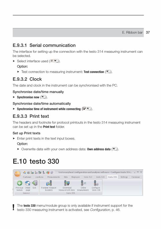
E.10 testo 330
The testo 330 menu/module group is only available if instrument support for thetesto 330 measuring instrument is activated, see Configuration, p. 46.
E. Ribbon bar 37

E.10.1 Transmit measure locationsLocations can be transmitted to the testo 330 measuring instrument using the Transmitmeasure locations module.
Open module
testo 330 ( ) Transmit measure locations ( ).
The Transmit measure locations module is separated into two areas. The Measure locationson PC folder is located in the upper area while the Measure locations on instrument folder islocated in the lower area.
E.10.1.1 Measure locations on PCThe Measure locations on PC folder shows the locations which are saved on the PC.
Search for a specific location
Enter search criterion in a search box Start search: Search ( ).
Transmit location(s) to measuring instrument
Options:
Select all locations: Select all ( ).
Cancel selection of locations: Select none ( ).
Select location(s) ( ) Transmit ( ).
Display location
Activate location ( ) Display ( ).
- The Show measure location data module is opened, see Show measure location data, p. 20.
Change location
Activate location ( ) Change ( ).
- The Change measure location data module is opened, see Change measure locationdata, p. 21.
E. Ribbon bar38
E.10.1.2 Measure locations on instrumentThe Measure locations on instrument folder shows the locations which are saved in theinstrument.
Delete llocation(s):
Options:
Select all locations: Select all ( ).
Cancel location selection: Select none ( ).
Select location(s) ( ) Delete ( ).
E.10.2 Download measurement data Measurement protocols in the testo 330 measuring instrument can be saved on your PCvia the Download measurement data module.
Open module
testo 330 ( ) Download measurement data ( ).
Save measurement protocol(s)
Options:
Select all measurement protocols: Select all ( ).
Cancel all measurement protocols: Select none ( ).
Select measurement protocol(s) ( ) Read ( ).
- The measurement protocol is saved on your PC in the same location as on theinstrument. If the location of the selected measurement protocol is not yet availableon your PC, it is set up automatically.
-oor-
Select measurement protocol(s) ( ) Download as ... ( ) Select targetlocation OK.
- The measurement protocol is saved on your PC in the location selected.
Delete measurement protocol
Select measurement protocol ( ) Delete ( ) Yes ( ).
- The measurement is deleted.
E. Ribbon bar 39
Display measurement protocol
If the selected location is not yet saved on your PC, this function is not available.
Select measurement protocol ( ) View ( ).
- The Display measurement data module is opened, see Display measurement data, p. 24.
E.10.3 Online measurementA flue gas measurement, during which the instrument is controlled by the PC, is carriedout via the Online measurement module. The readings are transmitted directly to your PCand displayed.
Open a module
testo 330 ( ) Online measurement ( ).
E.10.3.1 Measure values, Display, Chart
Carry out online measurementOnly parameters and measurement units are shown which are activated in the Displayorder folder (in the same module).
1 Set measurement cycle: ( ).
2 Set measurement sequence: ( ).
3 Start measurement: Start ( ).- Online measurement starts (initialisation phase may possibly run first)- The readings are displayed:
· Measure values folder: Table with all measurement channels and data/time of singlemeasurements.
· Display folder: Display fields with all measurement channels. During a measurement, mean value, maximum, minimum can be displayedinstead of the actual values:: Actual values ( ).
· Chart folder: Measurement diagram with 16 selectable measurement channels andautomatic scaling of the time axis.
Set diagram properties (channels displayed, line color, scaling ): Properties ( ).
Store diagram as a file: Store diagram ( ).
4 End measurement: Stop ( ).
- Online measurement is complete.
Options ((only iin rreadings ffolder):
Save readings in Online location: Save ( ).
Export readings to Microsoft Excel: Export Excel ( ).
E. Ribbon bar40
Export readings to clipboard (text file separated by tab stop): Clipboard ( ).
E.10.3.2 Display order
The measurement channels available are shown in the All channels area. Only theparameters and measuring units are available which are in the current display sequenceof the measuring instrument
The measurement channels, which appear on your PC during online measurement, areshown in the Shown channels area.
Setting up the display sequence
Add/delete measurement channels: Add ->, Add all ->, <- Delete or <- Delete all ( ).
Arrange order of measurement channels: Select measurement channel ( ) Up orDown ( ).
E.10.4 Configure testo 330The testo 330 analyser can be configured with the Configure testo 330 module.
Open module
testo 330 ( ) Configure testo 330 ( ).
E.10.4.1 InstrumentThe Instrument folder shows important information on the analyser connected.
E.10.4.2 Date/TimeThe data and time in the analyser can be synchronised with your PC in the Date/Timefolder.
Synchronise date/time manually
Synchronise now ( ).
Lock date/clock function in measuring instrument
Clock ccan bbe sset mmanually ( ).
It is only possible to change this function with this software.
E.10.4.3 Display editThe display sequence of the parameters and measurement units in the testo 330analyser is set in the Display edit folder.
E. Ribbon bar 41

Set display sequence
1 Select line which is to be changed ( ).
2 Select parameter and unit ( ).
Options:
Insert empty line: Insert line ( ).
Delete line: Delete line ( ).
E.10.4.4 Sensor settingsThe sensor protection settings in the testo 330 analyser can be carried out in the Sensorsettings folder.
Carry out settings
Enter value for adjustable criteria.
E.10.4.5 Print text The headers and footnote for the protocol printouts in the testo 330 analyser can be setup in the Print text folder.
Set up print texts
Enter print texts in the text input boxes.
Option:
Overwrite data with your own address data: Own address data ( ).
E.10.4.6 MemoryThe memory in the testo 330 analyser can be deleted in the Memory folder.
Delete memory
Delete all ( ).
E. Ribbon bar42
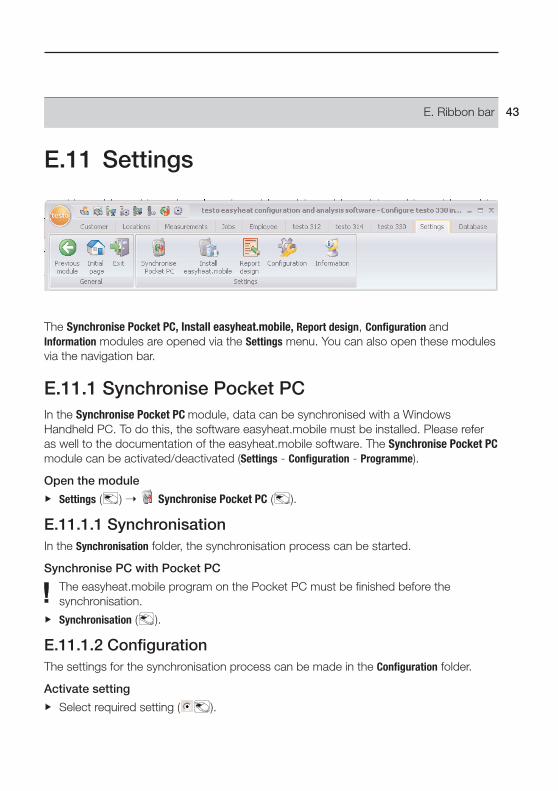
E.11 Settings
The Synchronise Pocket PC, Install easyheat.mobile, Report design, Configuration andInformation modules are opened via the Settings menu. You can also open these modulesvia the navigation bar.
E.11.1 Synchronise Pocket PCIn the Synchronise Pocket PC module, data can be synchronised with a WindowsHandheld PC. To do this, the software easyheat.mobile must be installed. Please referas well to the documentation of the easyheat.mobile software. The Synchronise Pocket PCmodule can be activated/deactivated (Settings - Configuration - Programme).
Open the module
Settings ( ) Synchronise Pocket PC ( ).
E.11.1.1 SynchronisationIn the Synchronisation folder, the synchronisation process can be started.
Synchronise PC with Pocket PC
The easyheat.mobile program on the Pocket PC must be finished before thesynchronisation.
Synchronisation ( ).
E.11.1.2 ConfigurationThe settings for the synchronisation process can be made in the Configuration folder.
Activate setting
Select required setting ( ).
E. Ribbon bar 43

E.11.2 Install easyheat.mobileThe easyheat.mobile software can be installed on a Windows Handheld PC using theInstall easyheat.mobile module. Please refer as well to the documentation of theeasyheat.mobile software.
An employee must be created before the installation, see New employee, p. 29.
Open the module
Settings ( ) Install easyheat.mobile ( ).
Install easyheat.mobile software on Pocket PC:
The Windows Pocket PC is connected to the PC.
1 Start installation ( ).
2 Follow the instructions of the installation program.
E.11.3 Report designThe forms for printing measurement protocols are changed according to userspecifications in the Report design module.
Opening the module
1 Settings ( ) Report design ( ).
- The measurement types to which a form is allocated are shown.
If the measurement type is not shown, the measurement protocols are printed in afixed standard layout. However, the user can set up a form specific to ameasurement type if so required:
New ( ) Activate measurement type ( ) OK ( ).
2 Activate measurement type for which the form is to be changed ( ) OK ( ).
The form designer module is separated into two areas. The Field, Font, Border and Pagefolders are located in the left area while the Editor and Preview folders are located in theright area.
Save form
Save ( ).
- The saved form is used for printing measurement protocols from the measurementtype selected.
E. Ribbon bar44
Save form as template
Backup as ... ( ) Enter form name OK ( ).
- The form is saved so that it can be restored if required.
Restore form
Restore form ... ( ) Select form name ( ) OK ( ).
- The form is restored.
Print form
Print ( ).
- The form is printed as it is shown in the Preview folder.
E.11.3.1 Field, Font, Border, PageThe box properties of the form boxes (field type, font and margin) and the pageproperties can be changed in the folders.
The displayed properties for box, font and margin are valid for the form box which isselected in the Editor folder (in the same module).
Set up box type
Select box type in Field ( ):· Textfield: Text is entered in the form box.
Enter text in the text box.· Data field: The selected data box value stored in the database (reading, customer or
system data) is entered in the form box.Select data box ( ).
· Graphics (Logo): The selected graphic is entered in the form box.Select graphic: File ... ( ) Select file Open ( ).
· Chart (measured data): The measurement protocol readings stored in the database areinput as graphics in the form box.
· Table: The measurement protocol readings stored in the database are input in tableform in the form box.
Select printing area ( ) Select range of table to be printed ( )Select data of table to be printed ( )
E. Ribbon bar 45

Determining the font
This function is only available if the Textfield or Data field box type is selected.
Select font in Font ( ):· Standard font: The standard font set in the Page folder is used.· Special font: A font deviating from the standard font is used.
Select font: Font ... ( ) Set values OK ( ).· Barcode: The “Barcode” font is used.Select alignment in the Alignment text box ( ).
Border settings
Select border properties for the form box in Border ( ).
Page settings
Page properties and the form standard font can be changed in the Page folder.
Input and set page properties ( ).
Define standard font: Default font ... ( ) Adjust values OK ( ).
E.11.3.2 EditorForm boxes can be inserted, modified in size and deleted in the Editor folder.
Insert new form box
Select corner point of form box on a free area of the form ( keep pressed) Drag form box until it is the right size End input, release ( ).
Move form box
Select form box ( and then keep pressed) Move form box to required positionEnd moving, release ( ).
Delete form box
Highlight form box ( ) [Del ] (keypad).
E.11.3.3 PreviewA preview of the form is shown in the Preview folder.
E.11.4 Configuration
Open module
Settings ( ) Configuration ( ).
E. Ribbon bar46

E.11.4.1 InstrumentsThe instruments which are to be supported by the software can be selected in theInstruments folder.
Activate required instruments ( ).
E.11.4.2 ProgrammeThe user-specific programme settings can be made in the Programme folder.
Perform required settings ( ).
E.11.4.3 Customer dataYou can enter presettings for setting up customer and location data in the Customer datafolder.
Activate required functions ( ).
E.11.4.4 Own dataYour own address data can be input in the Own data folder.
Own data ( ) Enter/change address data.
E.11.4.5 Color schemeIn the file Color scheme, the screen presentation can be selected.
Select desired screen presentation ( ).
E.11.4.6 BackupPresettings for data backups are made in the Backup folder.
To protect your data from a fault in the hard disk, your backup files should be savedon another data carrier.
Select directory for backup files
Search ( ) Select directory OK ( ).
Determine backup methods
Full backup ( ) Select required option ( ).
Changes backup ( ) Select required option ( ).
E.11.5 InformationThe Information module contains 4 folders in which important information for the PC usedand for the software is shown. This information is important if you contact our hotlineand will help us to diagnose the fault.
E. Ribbon bar 47

Open a module
Settings ( ) Information ( ).
E.12 Database
E.12.1 Full backup1 Full backup of data: Database ( ) Full backup ( ).
2 Confirm Information 3010: OK ( ).
E.12.2 Incremental backup1 Save changes since last data backup: Database ( ) Incremental backup ( ).
2 Confirm Information 3009: OK ( ).
E.12.3 Restore database1 Open Restore database window: Database ( ) Restore database ( ).
2 Restore data: Select time for restore ( ) OK ( ).
3 Confirm Information 3013: OK ( ).
E.12.4 Repair and compactFaults in the database occurring after a system crash or power failure can be corrected.
Repair faults in database: Database ( ) Repair and compact ( ).
E. Ribbon bar48

F. Questions and AnswersQuestion Possible reasons Answer
Uninstall software. - Use Windows uninstall routine.
If your query was not included, please contact your nearest distributor or Testo’sCustomer Service. You will find contact details in our Warranty booklet or in Internet atwww.testo.com.
F. Questions and answers 49

50

51
0971.0350/04/T/wh/08.02.2008
testo AG
Postfach 11 40, 79849 LenzkirchTesto-Straße 1, 79853 Lenzkirch
Telefon: (07653) 681-0Fax: (07653) 681-100
E-Mail: [email protected]: http://www.testo.com