testing vision cmms and the international … · bulletin no. 2183 testing vision cmms and the...
TRANSCRIPT

Bulletin No. 2183
TESTING VISION CMMS AND THE INTERNATIONAL STANDARD, ISO 10360-7
EDUC
ATIO
NA TECHNICAL PAPER FROM THE LEADING MANUFACTURER OF METROLOGY INSTRUMENTS
EDU-13002A
Whatever your challenges are, Mitutoyo supports you from start to finish.
Mitutoyo is not only a manufacturer of top-quality measuring products but one that also offers qualified support for the lifetime of the equipment, backed by comprehensive services that ensure your staff can make the very best use of the investment.
Apart from the basics of calibration and repair, Mitutoyo offers product and metrology training, as well as IT support for the sophisticated software used in modern measuring technology. We can also design, build, test and deliver measuring solutions and even, if deemed cost-effective, take your critical measurement challenges in-house on a sub-contract basis.
Coordinate Measuring Machines
Sensor Systems
Vision Measuring Systems
Test Equipment and Seismometers
Form Measurement
Digital Scale and DRO Systems
Optical Measuring
Small Tool Instruments and Data Management
Mitutoyo America Corporationwww.mitutoyo.comOne Number to Serve You Better1-888-MITUTOYO (1-888-648-8869)
M3 Solution Centers:Aurora, Illinois (Headquarters)Boston, MassachusettsHuntersville, North CarolinaMason, OhioPlymouth, MichiganCity of Industry, CaliforniaBirmingham, AlabamaRenton, WashingtonHouston, Texas
Mitutoyo Institute of MetrologyThe Mitutoyo Institute of Metrology provides educational courses and on-demand resources across a wide variety of measurement related topics including basic inspection techniques, principles of dimensional metrology, calibration methods, and GD&T. Visit www.mitutoyo.com/education for details on the educational opportunities available from Mitutoyo America Corporation.
About this Technical PaperISO 10360-7:2011 is the first international standard to address the calibration and testing of non-contacting coordinate measuring machines (CMMs) equipped with any type of imaging probing system, such as video or vision measuring instruments. This technical paper provides an overview of this new standard along with some insight into the options available in the standard. In particular, this paper explains how the tests in this standard can be used for the most modern three-dimensional measuring systems while still providing testing methods to meet the needs of older systems. Recommendations are also made regarding the use of the tests in this standard for the calibration of both old and new vision based CMMs. This paper was initially presented at the 2012 NCSL International Workshop and Symposium (www.ncsli.org).
© 2
016
Mitu
toyo
Am
erica
Cor
pora
tion
Mitutoyo America Corporation Education965 Corporate BoulevardAurora, Illinois 60502Phone: 888-648-8869 option 6Fax: 630-978-6471
Find additional product literature and our product catalog
www.mitutoyo.com
Trademarks and RegistrationsDesignations used by companies to distinguish their products are often claimed as trademarks. In all instances where Mitutoyo America Corporation is aware of a claim, the product names appear in initial capital or all capital letters. The appropriate companies should be contacted for more complete trademark and registration information.

Presented at the 2012 NCSL International Workshop and Symposium in Sacramento, CA
2012 NCSL International Workshop and Symposium Page 1 of 10
Developments in the International Standardization of Testing Methods for
CMMs with Imaging Probing Systems
James G. Salsbury
Mitutoyo America Corporation
945 Corporate Blvd.
Aurora, IL 60502
Phone: 630-723-3619
Fax: 630-978-6471
Email: [email protected]
Abstract
The first international standard to address the calibration and testing of certain types of non-
contacting measuring instruments was published in 2011. This important new standard addresses
the need for common testing methods and specifications for coordinate measuring machines
(CMMs) equipped with any type of imaging probing system, such as video or vision systems.
The standard, ISO 10360-7:2011, was developed by a working group within the ISO technical
committee 213. This paper provides an overview of this new standard along with some insight
into the options available in the standard. In particular, it will be shown how the tests in this
standard can be used for the most modern three-dimensional measuring systems while still
providing testing methods to meet the needs of older systems. Recommendations will also be
made regarding the use of the tests in this standard for the calibration of both old and new vision
based CMMs.
Learning Objectives
Identify the new ISO 10360-7 and recognize how the new standard fits within the ISO
10360 series of standards.
Interpret and apply the test methods in ISO 10360-7.
Compare the new test methods to prior methods and derive modern specifications and
calibration methods for older equipment.
1 Introduction
An important new international standard for the dimensional metrology community was
published in June 2011. To address the need for common testing methods and specifications for
certain types of non-contact measuring instruments, the working group on coordinate measuring
machines (CMMs) within the ISO technical committee 213 developed the new ISO 10360-
7:2011, Geometrical product specifications (GPS) – Acceptance and reverification tests for
coordinate measuring machines (CMM) – Part 7: CMMs equipped with imaging probing systems
[1]. This paper provides an overview of this new standard and provides some insight into the
options written into the standard. This author was the task force leader for the development of
this standard, but the content of this paper should not be considered as any type of official
interpretation of the standard.

2012 NCSL International Workshop and Symposium Page 2 of 10
2 ISO 10360 Series of Standards
Performance testing standards for CMMs began in 1985 with the publication of ASME/ANSI
B89.1.12 [2], and this was soon followed by related standards published by various groups and
standards bodies around the world. The historical evolution of CMM testing standards is shown
in Figure 1.
The first international standard for CMM testing, ISO 10360-2, was published in 1994 [3]. The
solidification and harmonization of CMM testing concepts around the world lead to the
publication of a new version of ISO 10360-2 in 2009 [4]. This latest version contains many
mature ideas that go beyond any prior national or international CMM test standards.
Until the publication of ISO 10360-7, all the CMM testing standards (such as those shown in
Figure 1), only applied to CMMs with contacting probing systems. The goal of ISO 10360-7 was
to extend the contacting probing testing ideas to a certain class of CMMs with non-contacting
probes. ISO 10360-7 was developed from ISO 10360-2:2009 and contains many of the same
concepts and much of the same language.
Figure 1. The evolution of national and international standards for testing CMMs.
3 Scope of ISO 10360-7:2011
There are many types of CMMs with non-contact probing systems. ISO 10360-7 only applies to
Cartesian CMMs using any type of imaging probing system and operating in the discrete point
probing mode. In the metrology market, the largest class of these instruments is the vision or
2012 NCSL International Workshop and Symposium Page 3 of 10
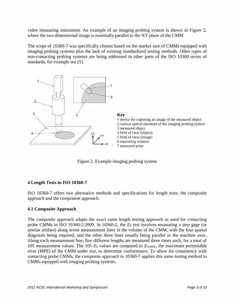
video measuring instrument. An example of an imaging probing system is shown in Figure 2,
where the two-dimensional image is nominally parallel to the XY plane of the CMM.
The scope of 10360-7 was specifically chosen based on the market size of CMMs equipped with
imaging probing systems plus the lack of existing standardized testing methods. Other types of
non-contacting probing systems are being addressed in other parts of the ISO 10360 series of
standards, for example see [5].
Key 1 device for capturing an image of the measured object
2 various optical elements of the imaging probing system
3 measured object
4 field of view (object)
5 field of view (image)
6 measuring window
7 measured point
Figure 2. Example imaging probing system
4 Length Tests in ISO 10360-7
ISO 10360-7 offers two alternative methods and specifications for length tests: the composite
approach and the component approach.
4.1 Composite Approach
The composite approach adapts the exact same length testing approach as used for contacting
probe CMMs in ISO 10360-2:2009. In 10360-2, the E0 test involves measuring a step gage (or
similar artifact) along seven measurement lines in the volume of the CMM, with the four spatial
diagonals being required, and the other three lines usually being parallel to the machine axes.
Along each measurement line, five different lengths are measured three times each, for a total of
105 measurement values. The 105 E0 values are compared to E0,MPE, the maximum permissible
error (MPE) of the CMM under test, to determine conformance. To allow for consistency with
contacting probe CMMs, the composite approach in 10360-7 applies this same testing method to
CMMs equipped with imaging probing systems.
+Y
+X
+Z

2012 NCSL International Workshop and Symposium Page 4 of 10
4.2 Bidirectional versus Unidirectional
In comparison to 10360-2, 10360-7 does allow one key difference in regards to the type of
artifact being used for the testing. For the E0 test in 10360-2, the test artifact must be measured in
a bidirectional manner, i.e. the two points that are used in the measurement of a length must be in
opposing directions. See Figure 3. In 10360-7, both bidirectional and unidirectional
measurements are allowed. The notation in 10360-7 is therefore slightly different than 10360-2;
EB and EU are used to indicate bidirectional or unidirectional testing to the corresponding EB,MPE
or EU,MPE specifications. The choice of specification is at the discretion of the CMM
manufacturer, and 10360-7 does not recommend one approach over the other.
Figure 3. Many artifacts, e.g. a linescale, allow both unidirectional measurements (U) and
bidirectional measurements (B). The artifact must be calibrated for the desired use.
4.3 Component Approach
The component approach is based on common industrial testing methods for imaging probe
CMMs and includes three separate tests. The first test is a modification of the 10360-2 E0 test
applied to the XY plane, EUXY or EBXY, and is tested along four measurement lines parallel to the
XY plane with a linescale or similar artifact (see Figure 4). The second test involves length
measurements parallel to the Z axis, EUZ or EBZ, and is tested along one measurement line with
gage blocks or similar artifacts (see Figure 5).
4.4 Z-axis Motion Relative to X and Y Axes
A major goal of 10360-7 was to ensure that imaging probe CMMs have three-dimensional
specifications. Even when these instruments are used for two-dimensional measurements, it is
common for the instrument to move in all three dimensions. As shown in Figure 6, when a
measurement involves projecting measured features into a common plane, such as is needed to
measure the distance between the two bores shown in the figure, the Z axis is typically moved up
or down. The error motion of the Z axis relative to the XY plane is often over-looked and can
result in large errors in what are usually considered to be just two-dimensional measurements.
This error motion is typically dominated by the Z-axis squareness error (to the X and Y axes)
B
U

2012 NCSL International Workshop and Symposium Page 5 of 10
and therefore 10360-7 has a Z-axis squareness test, ESQ. An example ESQ test using a square is
shown in Figure 7.
The measurement of a mechanical square for testing ESQ may require the use of an indicator, or
indicating gauge head, as shown in Figure 7. This approach has some drawbacks and was
carefully considered in the development of the 10360-7 standard. The standard also allows for
alternative testing approaches of ESQ.
Figure 4. Example testing of EUXY along one of two required planar face diagonals. The default
for the other two positions is parallel to the axes.
Figure 5. Example test of EUZ using one gage block stacked onto another one which is used as
the reference point.
4.5 Composite versus Component Approach
ISO 10360-7 offers two approaches to length testing and does not recommend one approach over
the other. The composite approach may be more useful when comparing the performance of
imaging probe CMMs to contacting probe CMMs. The component approach may be more useful
when comparing new imaging probe CMMs to prior products (which used similar
Test Length

2012 NCSL International Workshop and Symposium Page 6 of 10
specifications). The component approach may also be more useful when the measurement
application is primarily two-dimensional; however, both approaches address the three-
dimensional nature of the CMM. In addition, the MPE values associated with the two approaches
cannot necessarily be directly compared.
Figure 6. Measurement error associated with a squareness error in the XZ-plane. The Z’ axis
represents a possible error motion in an actual Z-axis, which results in measurement errors in
two-dimensional measurements, as shown.
Figure 7. Example test of ESQ with a square.
Measurement Error
+Y
+X
+Z
+Z’

2012 NCSL International Workshop and Symposium Page 7 of 10
5 Probing Tests in ISO 10360-7
In addition to length tests, ISO 10360-7 also includes a so-called probing performance test, PF2D,
which is based on other probing tests within the ISO 10360 series [6]. For PF2D a test circle is
measured using 25 points in a manner such that the CMM moves between all consecutive points
and that the measuring windows are distributed across the entire field of view. From the 25
points, a single circle is calculated and the form (maximum minus minimum radial distance) is
reported as the PF2D measured value. An example of an allowable measuring pattern for PF2D is
shown in Figure 8. The test circle for use in the PF2D test must be calibrated for the form of the
circle (i.e. the circle roundness).
a Test circle
b Field of view
c Measuring window
Figure 8. Example of an allowable test pattern for measuring PF2D. Note the distribution of the 25
measuring windows across the field of view.

2012 NCSL International Workshop and Symposium Page 8 of 10
6 Testing Field of View Separately
ISO 10360-7 offers two optional tests associated with the measuring performance of the field of
view separate from the rest of the CMM. The length test, EUV or EBV, and the probing test, PFV2D,
are similar to the tests described above but are done with no motion of the CMM. The test for
EUV or EBV is similar to EUXY and EBXY respectively but requires the four measurement lines to
be within the field of view. Similarly, the test for PFV2D is identical to that of PF2D but uses a
smaller circle that can be completely contained within the field of view. The specification of an
MPE associated with these field of view only tests is at the discretion of the imaging probe
CMM manufacturer.
10360-7 does not provide any recommendation concerning the application of these optional
specifications. EUV, EBV, or PFV2D will be more applicable to some imaging probe CMMs than
others, and some manufacturers may find these specifications useful to highlight features of their
particular instruments.
7 Specifications to ISO 10360-7:2011
A summary of the MPE specifications to ISO 10360-7:2011 that would be expected from the
imaging probe CMM manufacturers includes:
For the composite approach: For the component approach:
- EB,MPE or EU,MPE - EBXY,MPE or EUXY,MPE
- PF2D,MPE - EBZ,MPE or EUZ,MPE
- ESQ,MPE
- PF2D,MPE
For both approaches, the following are optional:
- EBV,MPE or EUV,MPE
- PFV2D,MPE
8 Options in ISO 10360-7:2011
Unlike most of the current test methods in the ISO 10360 series, 10360-7 offers a number of
options. These options include the composite versus component approach, the use of either
bidirectional or unidirectional artifacts, and the optional field of view only specifications. These
options allow for greater acceptance of the new standard in industry, but there is some risk that
too many options will lead to incomparable specifications. In the introduction clause of 10360-7,
it is mentioned that the differences between 10360-7 and 10360-2 may be eliminated in future
revisions of either standard.
9 Historical Specifications Compared to ISO 10360 Standards
It may be possible for older imaging probe CMMs to be tested following the latest ISO 10360
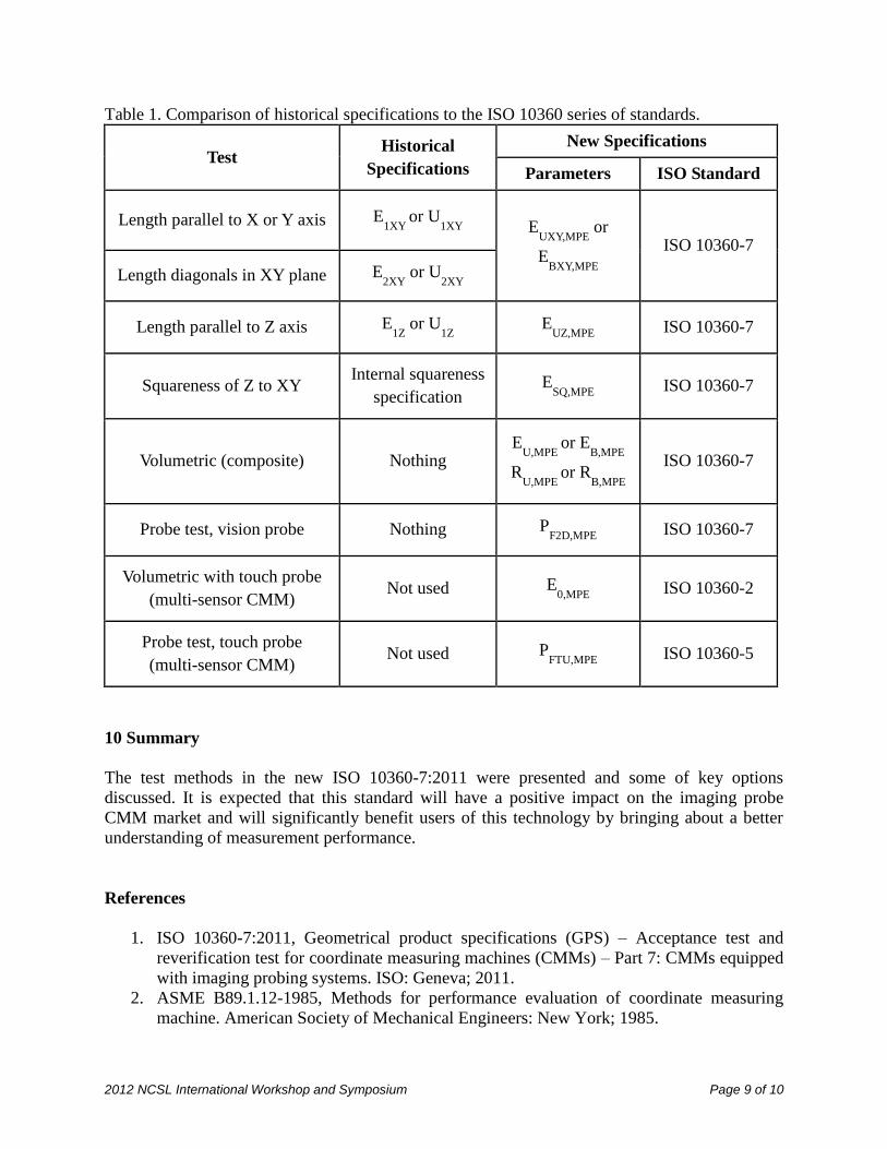
standards. Table 1 shows common historically listed manufacturer specifications in comparison
with the latest ISO 10360 standards.
2012 NCSL International Workshop and Symposium Page 9 of 10
Table 1. Comparison of historical specifications to the ISO 10360 series of standards.
Test Historical
Specifications
New Specifications
Parameters ISO Standard
Length parallel to X or Y axis E1XY
or U1XY
E
UXY,MPE or
EBXY,MPE
ISO 10360-7
Length diagonals in XY plane E2XY
or U2XY
Length parallel to Z axis E1Z
or U1Z
EUZ,MPE
ISO 10360-7
Squareness of Z to XY Internal squareness
specification E
SQ,MPE ISO 10360-7
Volumetric (composite) Nothing E
U,MPE or E
B,MPE
RU,MPE
or RB,MPE
ISO 10360-7
Probe test, vision probe Nothing PF2D,MPE
ISO 10360-7
Volumetric with touch probe
(multi-sensor CMM) Not used E
0,MPE ISO 10360-2
Probe test, touch probe
(multi-sensor CMM) Not used P
FTU,MPE ISO 10360-5
10 Summary
The test methods in the new ISO 10360-7:2011 were presented and some of key options
discussed. It is expected that this standard will have a positive impact on the imaging probe
CMM market and will significantly benefit users of this technology by bringing about a better
understanding of measurement performance.
References
1. ISO 10360-7:2011, Geometrical product specifications (GPS) – Acceptance test and
reverification test for coordinate measuring machines (CMMs) – Part 7: CMMs equipped
with imaging probing systems. ISO: Geneva; 2011.
2. ASME B89.1.12-1985, Methods for performance evaluation of coordinate measuring
machine. American Society of Mechanical Engineers: New York; 1985.

2012 NCSL International Workshop and Symposium Page 10 of 10
3. ISO 10360-2:1994, Coordinate metrology – Performance assessment of coordinate
measuring machine. ISO: Geneva; 1994.
4. ISO 10360-2:2009, Geometrical product specifications (GPS) – Acceptance test and
reverification test for coordinate measuring machines (CMMs) – Part 2: CMMs used for
measuring linear dimensions. ISO: Geneva; 2009.
5. ISO/DIS 10360-8, Geometrical product specifications (GPS) – Acceptance test and
reverification test for coordinate measuring machines (CMMs) – Part 8: CMMs with
optical distance sensors. ISO: Geneva; 2011.
6. ISO 10360-5:2010, Geometrical product specifications (GPS) – Acceptance test and
reverification test for coordinate measuring machines (CMMs) – Part 5: CMMs using
single and multiple stylus contacting probing systems. ISO: Geneva; 2010.