testing of yarns and fabrics (excluding colorfastness) sp15_2
DESCRIPTION
YARNSTRANSCRIPT

I
I
I
HANDBOOKOF
TEXTILE TESTING
Part 2 Testing of Yarns and Fabrics(Excluding Colourfastness)
(First Revision)
BUREAU OF INDIAN STANDARDSMANAK BHAVAN, 9BAHADkJRSHAH ZAFAR MARG
NEW DELHI 110002
I
1!

SP 15 (Part 2) :2000
FIRST PUBLISIl13D DECEMBER 2000
0 BUREAU OF INDIAN STANDARDS
w “-
‘A?‘,,..,
UDC 59.080.20; 59.080.30
ISBN 81-7061 -051-6
PRICE : Rs. 2200.00
TYPESET BY PRINTRADE, NEW DELHI 110 065
PRINTED IN INDIA BY VIBA PRESS PVT. LTD., 122 DSIDC SHEDS, OKHLA INDL. AREA PHASE-I, NEW DELHI 110020PUBLISHED BY THE BUREAU OF INDIAN STANDARDS, NEW DELHI 110002
I
i
——..—
FOREWORD
This part of the Handbook consists of five sections dealing with sampling and preparation of test samples/specimensfor testing various physical, physico-chemical, chemical and biochemical tests for yams and fabrics. The briefdetails of the methods/procedures covered in these sections are given below:
SECTION A
Contains the procedures for sampling and preparation of test samples/specimens for determination of physical andchemical characteristics of various textiles yams and fabrics.
SECTION B
Contains conditioning of textiles; physical tests for yams for various characteristics such as linear density, twist,strength parameters, commercial mass, unevenness, etc; and physical tests for fabric characteristics such as lengthand width, threads per unit length, weight per square meter and weight per linear meter, thickness, strength parameters,cgease recovery angle, pilling resistance, air permeability, stiffhess, thermal resistance, drape and abrasion resistanceetc. These methods of test are essential for controlling the quality, durability and end use suitability of various yamsand fabrics.
SECTION C
Contains physico-chemical tests for yams and fabrics for characteristics such as residual shrinkage, dimensionalchanges, nettability, absorbency, water repellency, water resistance, etc, which are useful in determining end usesuitability of the yam or fabric.
SECTION D
Contains chemical tests for determining various chemical characteristics such as chemical content in textile materials,scouring loss, residuai starch, properties of aqueous and organic extracts of textile materials, preservatives on textiles,soil resistance flammability and flame resistance, pH value, viscosity (or fluidity), copper number, etc. It alsoincludes tests for coated fabrics for characteristics such as mass of coating material, uniformity of coating, totalsolid content of coating materials, flexibility and effect of ageing.
SECTION E
Contains biochemical tests for detection and estimation of damage in textile yarns and fabrics due to micro-organismsand for determination of resistance of yams and fabrics to attack by micro-organisms.
The various methods of test included in this part of the Handbook are based on current national and internationalstandards.
The Indian Standards pertaining to various test methods included in this part of the Handbook have been broughtout by the following Sectional Committees :
TX 01 : Physical Methods of TestTX 02 : Cotton and Cotton ProductsTX 03 : Jute and Jute ProductsTX 04 : Wool and Wool ProductsTX 05 : Chemical Methods of TestTX 06 : Man-Made Fibre and Products
A number of test methods on coated and treated fabrics formulated by the Coated and Treated Fabrics SectionalCommittee of the Petro-Chemical Department of BIS have also been added. It would be pertinent to mention herethat test methods for evaluation of physical characteristics for silk yam and fabrics have not been included. Theseare under revision and it is intended to issue a separate compilation for the same at a later date.
,.
(iii)
/
SP 15 (Part 2) :2000.. .. --
INTRODUCTION .—..-
BIS Handbook of Textile Testing (SP 15: 1981) was first published in 1982 and has been taken up for revision toincorporate additional methods based on the standards which have come out after its publication. Opportunity hasalso been taken to incorporate latest version of the standards which have since been revised. The Handbook is nowbeing brought out in four parts wherein standards have been grouped on the basis of application and use:
Part 1 Testing and Grading of Textile Fibres
Part 2 Testing of Yams and Fabrics (Excluding Colour Fastness).
Part 3 Testing of Textile Products Other Than Yams and Fabrics.
Part 4 Identification and Testing of Dyestuffs and Their Colour Fastness on Textile Materials
The Handbook is basically a compilation of various Indian Standards on methods of test published by various
Sectional Committee under Textile Division Council. There are more than 300 standards covering a wide range ofphysical and chemical characteristics of textiles covered in the Handbook. Besides some methods of test and whichare included in the product specifications and no separate standards have not been published are also included in thepresent version of the Handbook wherever appropriate. As such the methods of test included in the Handbook
would satisfy the requirement of various sectors of textile industry like testing laboratories, research institutions, (
educational institutions in as far as the testing of the products like handloom and khadi, powerloom, hosiery, carpets,readymade garments, dyestuffs, textiIe auxiliaries, ropes and cordage, industrial textiIes, aerospace textiIes, etc, is .
concerned.
The objects of the Handbook are to :
. give the user details on all published national standards on methods of test for textiles;— help the various users to establish a suitable quality assurance system in the organization;— serve as a guide for the ordinary consumer to know the characteristics of textiles which are important with
reference to its end use; and— assist the textiIe technology/chemistry students, educational and research institutions in the selection of the
appropriate methods of test for various in depth studies/research.
Every effort has been made to make the various parts and sections self-contained but in certain cases relevant
provisions have been extracted and reproduced. In all such cases, for detailed guidance, reference should be madeto individual standards and in case of any contradiction observed between the Indian Standards and those reproducedherein; the provisions of the former should be considered accurate. On one hand, the Handbook is expected to be aself-contained reference document where as on the other, it is desirable to keep it less voluminous. The presentversion of the Handbook is the judicious choice with respect to the two aspects referred above.
/
Y
(iv)
I
SP 15 (Part 2) :2000
CONTENTS
Title
FOREWORD
INTRODUCTION
SECTION A: SAMPLING AND PREPARATIONOF TEST SAMPLEW3PECIMENS
A-1 Sampling
1. Sampling of cotton yam for determination ofphysical characteristics
2. Methods for sampling of cotton fabrics for determinationof physical characteristics
3. Sampling of cotton fabrics for chemical tests
4. Sampling of woollen fabrics
5. Sampling of man-made continuous filament flat yarn
A-2 Preparation of Test Samples/Specimens
1. preparation of test specimens from fabric
samples for physical tests
2. Methods for preparation of laboratory test samples andtest specimens of textile materials for chemical testing
SECTION B : PHYSICAL TESTS
B-1 General
1. Method for conditioning of textiles
B-2
1.
2.
3.
4.
5.
6.
7.
8.
9.
10.
11.
Tests for Yarns
Conversion factors and conversion tables for yam counts
Determination of linear density of yarns spun on cotton system
Determination of crimp and count of yarn removed from fabrics
Determination of universal count of woollen and worsted yarn
Determination of linear density of man-made fibres continuousfilament flat yarn
Determination of universal count of jute yarn
Determination of twist in yarn
Determination of yarn strength parameters of yarns spun on cotton system
Determination of breaking load and elongation at break of single strand
Determination of dry and wet tenacity and elongation of man-made fibrescontinuous filament flat yams
Determination of commercial mass of man-made fibre continuousfilament flat yams
Section Page No.
& (iii)
(iv)
A-111 3
A- 1/2 5
A- 1/3 8
A- 1/4 11
A-115 14
A-211 18
A-212 19
B-l/l
B-2/l
B-212
B-213
B-214
B-215
B-2/6
B-217
B-218
B-219
B-2I1O
B-2/l 1
25
27
42
45
49
52
54
57
62
66
71
73
(v)
I I
l’!
SP 15 (Part 2) :2000
12.
13.
14.
B-3
1.
2.
3.
4.
5.
6.
7.
8.
9.
10.
11.
12.
13.
14.
15.
16.
17.
18.
19.
20.
1.
2.
3.
4.
5.
6.
Title
Determination of correct invoice weight of all wool materials
Determination of unevenness percentage of continuous filamentpolyester and polyamide flat yarn
Grading for appearance of cotton yarn using photographic standards
Test for Fabrics
Determination of length and width of woven fabrics
Determination of threads per unit length in woven fabrics
Methods for determination of weight per square metre and weightper linear metre of fabrics
Determination of mass of jute fabrics
Determination of thickness of woven and knitted fabrics
Determination of breaking load and elongation of woven textile fabrics
Determination of bursting strength and bursting distention of fabrics :Diaphragm method
Determination of tear resistance by the falling pendulum method
Determination of seam strength of jute fabrics including their laminates
Determination recovery from creasing of textile fabrics by measuring the angleof recovery
Determination of pilling resistance of fabrics
Determination of air permeability of fabrics
Determination of stiffness of fabrics — Cantilever test
Determination of thermal resistance of textile fabrics guarded hot-plate method
Method for assessment of fabric drape
Determination of abrasion resistance of textile fabrics
Determination of pile height of hand-made carpets and handloom pile fabrics
Determination of terry ratio of towelling fabrics
Determination of wefi distortion of jute carpet backing fabric
Determination of correct invoice weight of woollen fabrics
SECTION C: PHYSIO-CHEMICAL TESTS
Preparation, marking and measuring of fabric specimens andgarments in tests for determination of dimensional change
Determination of dimensional stability of textile fabrics to dry heat
Determination of dimensional changes of woven fabrics on washingnear the boiling point
Determination of dimensional changes of fabrics containingwool on soaking in water
Determination of dimensional changes on washing of knittedgoods containing wool
Determination of dimensional changes on washing of fabrics wovenfrom rayon and synthetic fibres
Section
B-2/12
B-2113
B-2/14
B-3/l
B-312
B-3/3
B-3/4
B-315
B-3/6
B-317
B-318
B-319
B-3/10
B-3/l 1
B-3/12
B-3113
B-3114
B-3115
B-3/16
B-3/17
B-3118
B-3119
B-3120
Cil
C12
C13
c/4
C15
C/6
Page No.
75
77
80
83
88
92 .
95
97
99
105}
t,k
107
111I
114
117
123
125
28
31 ,.-
34 ,’---....
46,. .,t, .,
47
148
151
155
162
164
i.167
169
174
(vi)
/

,.. &
..—..-A
SP 15 (Part 2) :2000 1
7.
8.
9.
10.
11.
12.
13.
i 14.
15.
1.
2.
3.
4.
5.
6.
7.
8.
9.
10.
11.
12.
13.
14.
15.
16.
17.
18.
19.
20.
21.
22.
23.
24.
25.
26.
Title
Determination of dimensional changes of silk fabrics on washing
Determination of absorbency of absorbent textile materials
Determination of nettability of cotton fabrics
Determination of water repellency of fabrics by cone test
Determination of water repellency of fabrics by water spray test
Determination of water absorption and penetration of fabrics usingBundesmann type apparatus
Determination of resistance to penetration by water of fabricsby hydrostatic head test
Resistance to penetration by water of fabrics by static pressure head test
Determination of residual shrinkage of spun polyester sewing threads
SECTION D : CHEMICAL TESTS
Determination of wool content in woollen textile materials
Determination of bitumen content in laminated jute bags
Determination of oil content of jute yam and fabrics
Determination of hydrogen peroxide content in textile materials
Determination of sodium chlorite content in textile materials
Determination of sulphate content in textile materials
Determination of chloride content of textile materials
Estimation of residual chlorine in cotton textile materials
Determination of small quantities of copper, iron, manganese,chromium and zinc in textile materials
Determination of scouring loss in grey and finished cotton textile materials
Determination of scouring loss of rayon filament yarn
Determination of scouring loss in silk textile materials
Determination of water soluble chromate in textile materials
Determination of water soluble matter of textile materials
Estimation of benzene-methyl alcohol soluble matter in textile materials
Method for determination of ether soluble matter in textile materials
Determination of iron and chromium in textiles
Estimation of residual starch in cotton fabrics after desizing
Estimation of common preservatives
Determination of barium activity number of cotton textile materials
Determination of copper number of cotton textile materials
Determination of pH value of aqueous extracts of textile materials
Determination of viscosity (or fluidity) of solutions of cotton andregenerated celhdosic man-made fibres in cuprarnmonium hydroxide
Methods for determination of conductivity of aqueous and organicextracts of textile materials
Estimation of moisture, total size or finish, ash and fatty matter in grey andfinished cotton textile materials
Determination of soil resistance and soil release efficiencyof finished textile fabrics
Section
C17
C/8
c/9
Cllo
Cll 1
c/12
c/13
C114
c/15
D/l
D/2
D/3
D/4
D/5
D/6
D/7
D/s
D/9
DI1O
D/l 1
D/12
D/13
D/14
D/15
D/16
D/17
D/18
D/19
D120
D/2 1
D/22
D/23
D/24
D125
D/26
Page No.
178
181
183
185
187
190
197
199
202
205
207
209
211
212
214
217
221
223
240
242
244
246
249
251
253
255
258
260
281
284
289
292
300
303
308
-----
(vii)
.-.— ....-4
SP 15 (Part 2) :2000
Title
27. Determination of flammability and flame resistance of textile fabrics
28. Determination of flammability by oxygen index
29. Determination of the ignitability of upholstered composites for seating forfurniture by smokers’ materials
30. Evaluating the relative efficiency of wetting agents for mercerization
31. Methods of tests for coated and treated fabrics
— Determination of roll characteristics
— Determination of breaking strength and extension at break
— Determination of tear strength
— Determination of resistance to damage by flexing
— Determination of coating adhesion strength
— Determination of bursting strength
— Determination of resistance to penetration by water
— Accelerated ageing \
— Determination of blocking resistance
— Low-temperature bend test
— Determination of flexibility — Flat loop method
— Determination of tack-tear resistance
— Determination of crush resistance
— Low-temperature impact test
SECTION E : BIOCHEMICAL TESTS
1. Detection and estimation of damage in cotton yarn, cordageand fabrics due to micro-organisms
2. Tes~ing cotton fabrics for resistance to attack by micro-organisms
3. Detection and estimation of darnage in jute yarn, cordage and fabricsdue to micro-organisms
4. Testing of jute fabrics for resistance to attack by micro-organisms
5. Method for testing flax fabrics for resistance to attack by micro-organisms
6. Method of test for evaluation of insectproofness of woollen textiles
7. Determination of desizing efficiency and the relative efficiencyof amylolytic enzymes
Section Page No.
D/~7 313
D/28 323
D129 330
D130 337
D131.1
D/3 1.2
D131.3
D/3 1.4
D/31.5
D/3 1.6
D131.7
D/31.8
D/31.9
DI31.1O
D131.11
D131.12
D/31.13
D131.14
340
343
345
349
353
356
360
363
365
367
370
372
374
376
E/l 383
E12 386
E/3 394
E/4 399
E15 406
E/6 412
E/7 417
1’
(viii)
—...4
SP 15 (Part 2) :2000
... ..~
SECTION A
SAMPLING AND PREPARATION OFTEST SAMPLES/SPECIMENS

As in the Original Standard, this Page is Intentionally Left Blank

-.. ..—
1 SCOPE
SP 15 (Part 2) :2000
SAMPLING OF COTTON YARN FOR DETERMINATION
OF PHYSICAL CHARACTERISTICS
(Source:IS 3920: 1985)
It prescribes the procedure for sampling of cotton yarnfor determination of physical characteristics, namely,count, lea breaking load, twist, evenness percentage andappearance grade. It specifies the number of tests thatshould be made for each characteristic. It also lays downthe criteria for ascertaining the conformity of the yarn tothe specified requirements of the characteristics.
2 NUMBER OF TESTS
2.1 The minimum number of tests to be made fordetermination of average values of various characteristicsof yam in a lot shall depend upon the accuracy with whichthe averages are to be determined. Table 1 gives thenumber of tests necessary for determination of averagevalues of count, lea breaking load, evenness and twistfor varying limits of error.
NOTE — Limit of error of meau is the maximum differencebetween the sample mean and its true value (that would beobtained if aIl the units in the lot were tested) at a given probabilitylevel.
2.1.1 Unless otherwise agreed to between the buyer andthe seller, 25 tests for count, and lea breaking load and10 tests for evenness and twist shall be made forevaluation of average values.
2.1.2 For inspection for appearance grade five packagesshall be selected at random from a lot and one testspecimen shall be prepared from each package. As faras possible equal number of packages shall be selected
~from each bale/case. When the number of bales/cases is8 or 13 five bales/cases shall be selected at random and
& from each bale/case one package shall be selected.
2.2 The minimum number of tests to be made fordetermination of coefficient of variation of variouscharacteristics of yam in the lot shall depend upon the
accuracy with which the coefficient of variation (CV) isto be determined. Table 2 gives the number of testsnecessary for determination of coefficient of variationof count and lea breaking load for varying limits of error.
NOTE —Coefllcient of variation (CV) is the ratio of the standarddeviation to the absolute value of the mean expressed aspercentage. Limit of error of CV is the maximum differencebetween the CV of the sample and true value of CY (that would
1be obtained if all the units in the lot were tested) at a given
& probability level.
Table 1 Number of Tests(Clauses 2.1 and3.3.1)
Characteristic Limit of Error of Mean (Percent)
~
Count 25 15 10 5 - - –Lea breakhg 100 45 25 20 15 10 5loadEvenness 80 35 20 15 10 5 -percentage
Twist 65 30 28 10 7 5 -
NOTE — Wherever the number of tests have become too smaIl theyhave not been specified.
Table 2 Number of Tests for Determination of CV(Clauses 2.2 and2.2.1)
Limit of Error of CV
(Percent)
(1)
4
5
8
10
15
20
30
Number of Tests
(2)
1200
8003002009050
25
2.2.1 It can be seen fi-om Table 2 that 200 tests arerequired for determination of coefficient of variation withan accuracy of 10 percent. However, for a manufacturingconcern, the coefficient of variation can be determinedfrom routine tests conducted over a period of time toany degree of accuracy required.
3 SAMPLING
3.1 Test specimens shall be sampled from each lot for
determination of physical characteristics of yarn. In order
that the test specimens selected be representative of the
lot, they shall be distributed over the bales or cases in
the lot, packages in a bale or case and skeins of yam
within packages. Unless otherwise agreed to between
the buyer and the seller, the number of bales or cases to
be taken from a lot for the purpose shall depend upon
the size of the lot and be in accordance with Table 3.
PART 2, SECTION A-l/l
/
3
I
1 ,,,
. A
.—
SP 15 (Part 2) :2000
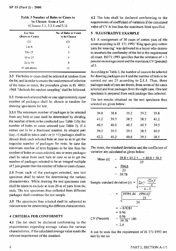
Table 3 Number of Bales or Cases tobe Chosen from a Lot
(C/auses 3.1, 3.3.1 and5.1)
Lot Size
(Bales or Cases)
(1)
2t08
9to 15
16t025
26 to 50
51 and above
No. of Bales or Casesto be Chosen
(2)
2
3
5
8
13
3.2 The bales or cases shall be selected at random from
the lot, and in order to ensure the randomness of selection
of the bales or cases, the procedure given in IS 4905:
1968 ‘Methods for random sampling’ shall be followed.
3.3 From each selected bale or case approximately equal
number of packages shall be chosen at random for
drawing specimens for test.
3.3.1 The minimum number of packages to be selected
from any bale or case shall be determined by dividing
the number of tests to be conducted (see Table 1) by the
number of bales or cases selected (see Table 3). If it
comes out to be a fractional number, its integral part
(say, r) shall be taken and r or (r +1) packages shall be
chosen from each selected bale or case so as to get the
requisite number of packages for tests. In case the
minimum number of tests happens to be less than the
number of bales or cases selected, one or more packages
shall be taken from each bale or case so as to get the
number of packages selected to be an integral multiple
of 5 just greater than the number of bales or cases chosen.
3.4 From each of the packages selected, one test
specimen shall be taken for determining the various
characteristics. While drawing the test specimens care
shall be taken to exclude at least 20 m of yarn from the
ends. The test specimens thus collected from different
packages shall constitute the test sample.
3.5 The specimens thus selected shall be subjected to
relevant tests for determining the different characteristics.
4 CRITERIA FOR CONFORMITY
4.1 The lot shall be declared conforming to the
requirements regarding average values for various
characteristics, if the calculated average value meets the
relevant requirement of the standard.
4.2 The lots shall be declared conforming to the
requirements of coefficient of variation if the calculated
value of CV is less than the maximum limit specified.
5 ILLUSTRATIVE EXAMPLE
5.1 A consignment of 30 cases of cotton yam of 40s
count according to IS 171:1993 ‘Ring spun grey cotton
yam for weaving’ was delivered to a buyer who desires
to ascertain the conformity of the lot to the requirement
of count. IS171: 1993 specifies that the tolerance of+ 3
percent on average count and the maximum CV (percent)
of5.
According to Table 3, the number of cases to be selected
for drawing packages are 8 and the number of tests to be
carried out are 25 according to 2.1.1. Thus, three
packages each of yam are drawn, from seven of the cases
selected and four packages from the eight case. One test
specimen is prepared from each package thus selected.
The test results obtained on the test specimen thus
selected are given below:
39.8 38.8 39.2 39.2 39.8
41.2 39.5 38.2 38.5 41.2
40.5 40.0 40.5 40.5 39.5
39.5 39.5 39.5 38.5 40.0
42.2 40.2 40.8 39.5 38.5
The mean, the standard deviation and the coefficient ofvariation are calculated as given below:
Mean (i) = 3.9.8 +41.2 + ... +40.0+ 38.525
.=25
= 39.78
JSample standard deviation (s) = ~,’- $?#
n–1——
“139591.44 – (994.6)225
24,,
—— ~ 0.9281
= 0.96_ 0.96
CV (Percent) – ~X 100
= 2.4 !
It can be seen that the requirement of IS 171:1993 are \
met by the lot.
/
4 PART 2, SECTION A- 1/1
.,d——
.——
SP 15 (Part 2) :2000
METHODS FOR SAMPLING OF--q
COTTON FABRICS FOR DETERMINATION
OF PHYSICAL CHARACTERISTICS d-1,. ----
(Source : IS 3919: 1966)
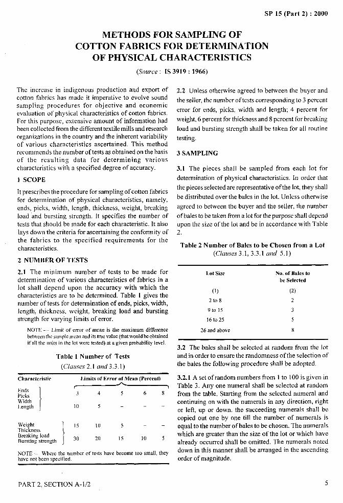
The increase in indigenous production and export ofcotton fabrics has made it imperative to evolve soundsampling procedures for objective and economicevaluation of physical characteristics of cotton fabrics.For this purpose, extensive amount of information hadbeen collected from the different textile mills and researchorganizations in the country and the inherent variabilityof various characteristics ascertained. This methodrecommends the number of tests as obtained on the basisof the resulting data for determining variouscharacteristics with a specified degree of accuracy.
1 SCOPE
It prescribes the procedure for sampling of cotton fabricsfor determination of physical characteristics, namely,
ends, picks, width, length, thickness, weight, breakingload and bursting strength. It specifies the number oftests that should be made for each characteristic. It alsolays down the criteria for ascertaining the conformity ofthe fabrics to the specified requirements for the
1 characteristics.
2 NUMBER OF TESTS
2.2 Unless otherwise agreed to between the buyer and
the seller, the number of tests corresponding to 3 percent
error for ends, picks, width and length; 4 percent for
weight, 6 percent for thickness and 8 percent for breaking
load and bursting strength shall be taken for all routine
testing.
3 SAMPLING
3.1 The pieces shall be sampled from each lot for
determination of physical characteristics. In order that
the pieces selected are representative of the lot, they shall
be distributed over the bales in the lot. Unless otherwise
agreed to between the buyer and the seller, the number
of bales to be taken from a lot for the purpose shall depend
upon the size of the lot and be in accordance with Table2.
Table 2 Number of Bales to be Chosen from a Lot(Ckwse,s3.1, 3.3.1 and 5.1)
2.1 The minimum number of tests to be made for
1determination of various characteristics of fabrics in alot shall depend upon the accuracy with which thecharacteristics are to be determined. Table 1 gives thenumber of tests for determination of ends, picks, width,
II
length, thickness, weight, breaking load and bursting
1
strength for varying limits of error.
NOTE — Limit of error of mean is the maximum differencebetweenthe salmplemean and itstrue value (thatwould be obtained
I
if all the units in the lot were tested) at a given probability level.
Table 1 Number of Tests
(Clauses 2.1 and 3.3. 1)
Characteristic
EndsPicksWidthLength 1
Limits of Error of Mean (Percent)
r 3
3 4 5 6 8
10 5 ---
Weight 15 10 5 — —ThicknessBreaking loadBursting strength 30 20 15 10 5
/NOTE — Where the number of tests have become too small, theyhave not been s~ecified.
Lot Size No. of Bales to
be Selected
(1) (2)
2t08 2
9t015 3
16t025 5
26 and above 8
$,,..
3.2 The bales shall be selected at random from the lotand in order to ensure the randomness of the selection ofthe bales the following procedure shall be adopted.
3.2.1 A set of random numbers from 1 to 100 is given inTable 3. Any one numeral shall be selected at randomfrom the table. Starting from the selected numeral andcontinuing on with the numerals in any direction, rightor left, up or down, the succeeding numerals shall becopied out one by one till the number of numerals isequal to the number of bales to be chosen. The numeralswhich are greater than the size of the lot or which havealready occurred shall be omitted. The numerals noteddown in this manner shall be arranged in the ascendingorder of magnitude.
8 PART 2, SECTION A-1/2 5

SP 15 (Part 2) :2000
Table 3 Random Number Table
(Clausef 3.2.1 and 5.1)
81 74
61 37
52 07
43 08
65 32
21 58
31 90
73 98
33 15
75 66
67
42
16
77
27
11
55
20
35
99
95
62
29
25
40
23
88
05
26
09
70 56 51 54 50 53
93 96 34 18 22 88
39 04 71 14 76 78
72 49 86 03 83 45
63 57 97 84 82 87
80 10 30 01 100 44
13 36 24 91 19 64
68 46 69 85 94 59
79 92 38 12 41 17
06 47 48 60 28 .02
3.2.2 Starting from any bale in the lot and counting themin one order, the bales corresponding to numerals alreadynoted down shall be selected from the lot for drawingsamples.
3.3 From each selected bale approximately equalnumber of pieces shall be chosen at random.
3.3.1 The minimum number of pieces to be selected ti-omany bale shall be determined by dividing the number oftests to be conducted (see Table 1) by the number ofbales selected (see Table 2). If it comes out to be atractional number, its maximum integral part (say 1)shallbe taken and 1or (1+1) pieces shall be chosen fi-om eachselected bale so as to get the requisite number of piecesfor tests. In case the minimum number of tests happensto be five and the number of bales selected to be eight,one or more pieces shall be taken from each bales so asto get ten pieces for test purposes.
3.4 In case the lot is not in the form of bales or cases butoffered as pieces as such, the number of pieces to beselected at random from a lot for testing for a particularcharacteristic shall be equal to the number of testsrequired to be carried out according to 2.
3.4.1 To ensure the randomness of selection of piecesthe procedure given in 3.1 or 3.3 of IS 4905: 1968‘Methods for random sampling’, shall be folIowed.
3.5 From each of the pieces selected, one test specimenshall be taken for determining the various characteristics.While drawing the test specimens care shall be taken toexclude a suitable length from both ends of the piece.
3.6 The test specimens thus selected shall besubjected to relevant tests for determining the differentcharacteristics.
4 CRITERIA FOR CONFORMITY
4.1 For ascertaining the conformity of the lot to the
specification requirements, the following procedure
shall be adopted.
4.1.1 For One-sided Specification Limit
The lot shall be declared as conforming to the
specification ifi
a) the value of the expression (Y+kR) or (Y + k~) isless than or equal to U, when the upperspecification limit U is given; or
b) the value of the expression (T–kR) or (Y–kx) isgreater than or equal to L, when the Iowerspecification limit L is given;
where the values of the factor k are given in Table 4 for
different sample sizes, and U and L refer to thespecification limits for individual test result.
4.1.2 For Two-sided Speclf2cation Limit
The lot shall be declared as conforming to the
specification it
a) the value of the expression R/(U– L) or
i7cJ– L)s B;
b) the value of the expression (1+ kR)
or (X + k~) < V, and
c) the value of the expression (X – kR)
or (7 – k~) 2 L;
where the value of factors B and k are given in Table 4for different sample sizes, and U and L refer to thespecification limits for individual test results.
NOTE-The explanationofvarious symbols is giveninAnnexA.
Table 4 Values of the Factors
Sample Size k B(n)
(1) (2) (3)
5 0.3 1.0
10 0.4 0.9 !,
15 and above 0.5 0.8
5 ILLUSTRATIVE EXAMPLE
5.1 A seller delivers to a buyer a consignment consistingof 50 bales, of which 20 bales consist of cotton umbrellacloth (waterproof) and the remaining 30 bales consist of Icotton brill (non-waterproof) for umbrella. The buyerdesires to ascertain the conformity of the fabrics supplied
6 PART 2, SECTION A-1/2I
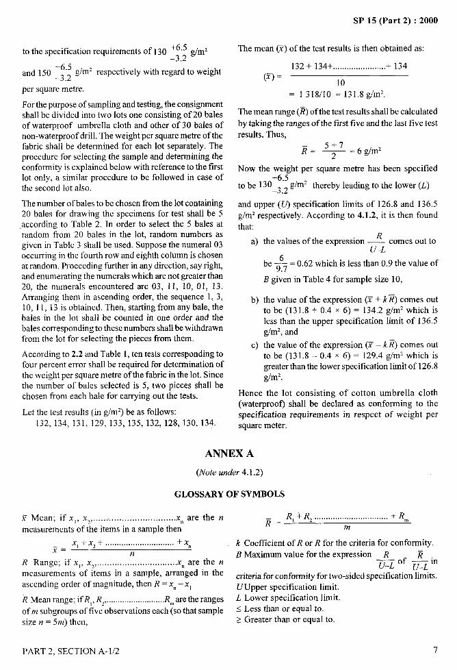
to the specification requirements of 130 ‘6”5-3.2 ‘m’
‘6”5 glmz respectively with regard to weightand 150 –3.2per square metre.
For the purpose of sampling and testing, the consignmentshall be divided into two lots one consisting of 20 balesof waterproof umbrella cloth and other of 30 bales ofnon-waterproof drill. The weight per square metre of thefabric shall be determined for each lot separately. Theprocedure for selecting the sample and determining theconformity is explained below with reference to the firstlot only, a similar procedure to be followed in case ofthe second lot also.
The number of bales to be chosen from the lot containing20 bales for drawing the specimens for test shall be 5according to Table 2. In order to select the 5 bales atrandom from 20 bales in the lot, random numbers asgiven in Table 3 shall be used. Suppose the numeral 03occurring in the fourth row and eighth column is chosenat random. Proceeding further in any direction, say right,and enumerating the numerals which are not greater than20, the numerals encountered are 03, 11, 10, 01, 13.Arranging them in ascending order, the sequence 1, 3,10, 11, 13 is obtained. Then, starting from any bale, thebales in the lot shall be counted in one order and thebales corresponding to these numbers shall be withdrawnfrom the lot for selecting the pieces from them.
According to 2.2 and Table 1, ten tests corresponding tofour percent error shall be required for determination ofthe weight per square metre of the fabric in the lot. Sincethe number of bales selected is 5, two pieces shall bechosen from each bale for carrying out the tests.
Let the test results (in g/m2) be as follows:132, 134, 131, 129, 133, 135, 132, 128, 130, 134.
SP 15 (Part 2) :2000
The mean (X) of the test results is then obtained as:
132 + 134+ .......................+ 134(Y) =
10
= 1 318/10 = 131.8 g/m’.
The mean range (~) of the test results shall be calculated
by taking the ranges of the first five and the last five test
results. Thus,
~= 5+7— = 6 glm2
2
Now the weight per square metre has been specified+6.5
to be 130_3 z g/m2 thereby leading to the lower (L)
and upper (U) specification limits of 126.8 and 136.5
g/m2 respectively. According to 4.1.2, it is then found
that:
a)
b)
c)
Rthe values of the expression — comes out to
U–L
be+ = 0.62 which is less than 0.9 the value of
B given in Table 4 for sample size 10,
the value of the expression (Y+ k ~) comes outto be (131.8 + 0.4 x 6) = 134.2 g/m2 which isless than the upper specification limit of 136.5glmz, and
the value of the expression (Z – k @ comes outto be (131.8 – 0.4 x 6) = 129.4 g/mz which isgreater than the lower specification limit of 126.8g/m2.
Hence the lot consisting of cotton umbrella cloth(waterproof) shall be declared as conforming to thespecification requirements in respect of weight persquare meter.
ANNEX A
(Note under 4.1.2)
GLOSSARY OF SYMBOLS
T Mean; if xl, X2, . . . . . . . . . . . . . . . . . . . . . . . . . . . . . . . .Xn are the n
measurements of the items in a sample then
xl +X2+ ... .. . .. .. . ... .. . .. .. ... . ... .. +x~= n
nR Range; if x,, Xl, .. .. . .. .. .. .. . ... .. . .. .. ... .. ...X. are the nmeasurements of items in a sample, arranged in theascending order of magnitude, then R = x“ – xi
~ Mean range; if R,, R,,. .........................Rlmaretheranges
of m subgroups of five observations each (so that samplesize n = 5m) then,
R, +R2 ................................ + R,~~=
m
k Coefficient of R or ~ for the criteria for conformity.
B Maximum value for the expression R R.—_U–L ‘f II–I, In.—
criteria for conformity for two-sided specification limits.UUpper specification limit.L Lower specification limit.< Less than or equal to.> Greater than or equal to.
PART 2, SECTION A-1/2 7
/
,,
SP 15 (Part 2) :2000
SAMPLING OF COTTON FABRICS FOR
CHEMICAL TESTS(Source : IS 5463:1969)
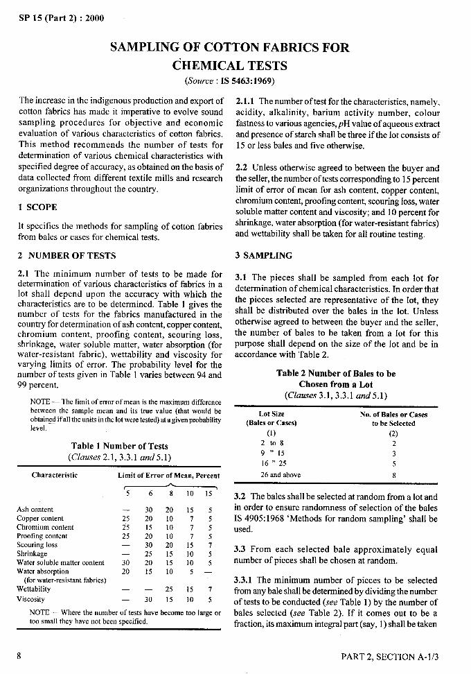
The increase in the indigenous production and export ofcotton fabrics has made it imperative to evolve soundsampling procedures for objective and economicevaluation of various characteristics of cotton fabrics.This method recommends the number of tests fordetermination of various chemical characteristics withspecified degree of accuracy, as obtained on the basis ofdata collected from different textile mills and researchorganizations throughout the country.
1 SCOPE
It specifies the methods for sampling of cotton fabricsfrom bales or cases for chemical tests.
2 NUMBER OF TESTS
2.1 The minimum number of tests to be made fordetermination of various characteristics of fabrics in alot shall depend upon the accuracy with which thecharacteristics are to be determined. Table 1 gives thenumber of tests for the fabrics manufactured in thecountry for determination of ash content, copper content,chromium content, proofing content, scouring loss,shrinkage, water soluble matter, water absorption (forwater-resistant fabric), nettability and viscosity forvarying limits of error. The probability level for thenumber of tests given in Table 1 varies between 94 and99 percent.
NOTE— The limit of error of mean is the maximum differencebetween the sample mean and its true value (that would beobtained if all the units in the lot were tested) at a given probabilitylevel.
Table 1 Number of Tests(Clauses 2.1, 3.3.1 arrd5.1)
Characteristic
Ash contentCopper contentChromium contentProofing contentScouring lossShrinkageWater soluble matter contentWater absorption
(for water-resistant fabrics)Nettability
Viscosity
Limit of Error of Mean, Percent
~
— 30 20 15 525 20 10 7 525 15 10 7 525 20 10 7 5— 30 20 15 7— 25 15 10 530 20 15 10 520 15 10 5 —
— . 25 15 7— 30 15 10 5
NOTE — Where the number of tests have become too large ortoo small they have not been specified.
8
2.1.1 The number of test for the characteristics, namely,acidity, alkalinity, barium activity number, colourfastness to various agencies,pH value of aqueous extract
and presence of starch shall be three if the lot consists of15 or less bales and five otherwise.
2.2 Unless otherwise agreed to between the buyer andthe seller, the number of tests corresponding to 15 percentlimit of error of mean for ash content, copper content,
chromium content, proofing content, scouring loss, watersoluble matter content and viscosity; and 10 percent forshrinkage, water absorption (for water-resistant fabrics)and nettability shall be taken for all routine testing.
3 SAMPLING
3.1 The pieces shall be sampled from each lot fordetermination of chemical characteristics. In order thatthe pieces selected are representative of the lot, they
shall be distributed over the bales in the lot. Unlessotherwise agreed to between the buyer and the seller,the number of bales to be taken from a lot for thispurpose shall depend on the size of the lot and be inaccordance with Table 2.
Table 2 Number of Bales to beChosen from a Lot
(Ckztfse,s 3.1, 3.3.1 and5.1)
Lot Size No. of Bales or Cases(Bales or Cases) to be Selected
(1) (2)
2t08 2
9 “ 15 3
16 “ 25 5
26 and above 8
3.2 The bales shall be selected at random from a lot andin order to ensure randomness of selection of the balesIS 4905:1968 ‘Methods for random sampling’ shall beused.
3.3 From each selected bale approximately equalnumber of pieces shall be chosen at random.
3.3.1 The minimum number of pieces to be selectedfrom any bale shall be determined by dividing the numberof tests to be conducted (see Table 1) by the number ofbales selected (see Table 2). If it comes out to be afraction, its maximum integral part (say, 1) shall be taken
PART 2, SECTION A- 1/3
,,
i’,
ii
4-
.-—
SP 15 (Part 2) :2000
and 1or (/ + 1) pieces shall be chosen from each selectedbales so as to get the requisite number of pieces for test.In case the minimum number of tests happens to be lessthan the number of bales selected, one or more piecesshall be taken from each bale so as to get the number ofpieces in multiple of five for test purposes.
3.4 From each of the pieces selected, one test specimenshall be taken for determining the various characteristics.
3.5 In case the lot is not in the form of bales or cases,but offered as pieces as such, the number of pieces to beselected at random from a lot for testing for a particularcharacteristics shall be equal to be number of testsrequired to be carried out according to 2.
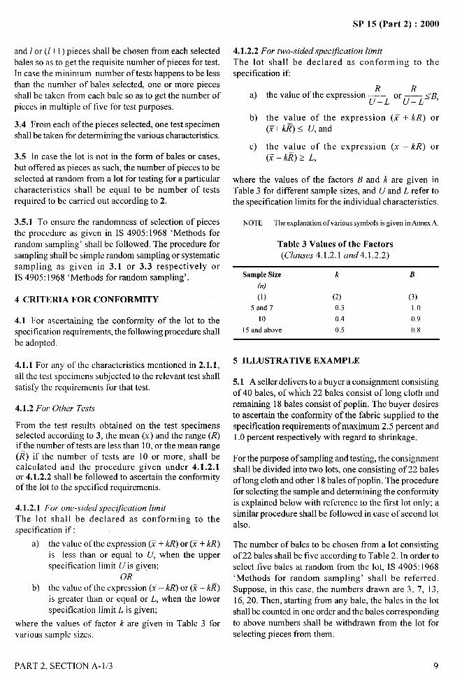
4.1.2.2 For two-sided specljication limit
The lot shall be declared as conforming to the
specification ifi
R Ra) the value of the expression — —
U–L OrU–L<B’
b) the value of the expression (,T + kR) or(z+ k~) < U, and
c) the value of the expression (Y – H?) or(x - k~) > L,
where the values of the factors B and k are given inTable 3 for different sample sizes, and U and L refer tothe specification limits for the individual characteristics.
3.5.1 To ensure the randomness of selection of pieces NOTE— The explanation of various symbolsisgiveninAnnexA.the procedure as given in IS 4905:1968 ‘Methods forrandom sampling’ shall be followed. The procedure for Table 3 Values of the Factorssampling shall be simple random sampling or systematic (Ckwses 4.1.2.1 and 4.1 .2.2)
sampling as given in 3.1 or 3.3 respectively orIS 4905:1968 ‘Methods for random sampling’. Sample Size k B
(n)
4 CRITERIA FOR CONFORMITY (1) (2) (3)
5 and 7 0.3 I ,0
4.1 For ascertaining the conformity of the lot to the 10 0.4 0.9
specification requirements, the following procedure shall 15and above 0.5 0.8
be adopted.
4.1.1 For any of the characteristics mentioned in 2.1.1, 5 ILLUSTRATIVE EXAMPLE
all the test specimens subjected to the relevant test shall5.1 A seller delivers to a buyer a consignment consisting
satisfy the requirements for that test.of 40 bales, of which 22 bales consist of long cloth and
4.1.2 For Other Tests
From the test results obtained on the test specimensselected according to 3, the mean (Y) and the range (R)if the number of tests are less than 10, or the mean range(~) if the number of tests are 10 or more, shall becalculated and the procedure given under 4.1.2.1or 4.1.2.2 shall be followed to ascertain the conformityof the lot to the specified requirements.
4.1.2.1 For one-sided specljication limit
The lot shall be declared as conforming to thespecification if:
a) the value of the expression (Y + kR) or (Y + k~)is less than or equal to U, when the upperspecification limit U is given;
OR
b) the value of the expression (1– kR) or (Z– k~)is greater than or equal or L, when the lowerspecification limit L is given;
where the values of factor k are given in Table 3 forvarious sample sizes.
remaining 18 bales consist of poplin. The buyer desiresto ascertain the conformity of the fabric supplied to thespecification requirements of maximum 2.5 percent and1.0 percent respectively with regard to shrinkage.
For the purpose of sampling and testing, the consignmentshall be divided into two lots, one consisting of 22 balesof long cloth and other 18 bales of poplin. The procedurefor selecting the sample and determining the conformityis explained below with reference to the first lot only; asimilar procedure shall be followed in case of second lotalso.
The number of bales to be chosen from a lot consistingof 22 bales shall be five according to Table 2. In order toselect five bales at random from the lot, IS 4905:1968‘Methods for random sampling’ shall be referred.
Suppose, in this case, the numbers drawn are 3, 7, 13,16,20. Then, starting from any bale, the bales in the lot
shall be counted in one order and the bales correspondingto above numbers shall be withdrawn from the lot for
selecting pieces from them.
. . ...-a
),
PARr 2, SECTION A-1/3 9
I
I~: II
.
*. —.-A
SP 15 (Part 2) :2000
According to 2.2 and Table 1, ten tests correspondingto ten percent error shall be required fordetermination of shrinkage of the fabrics in the lot.Since the number of bales selected is five, two piecesof fabric shall be chosen from each bale for carryingout the tests.
Let the test results for warpway shrinkage (expressed as
percentage) be as follows:
18,23, 18, 17, 15, 18, 1.3, 18,20,20
The mean (1) of the test results is obtained as:
18 +23 + ........... +20~=10
(18 0/10) = 180
The mean range (~) of the test results shall be calculatedby taking the ranges of the first five and last five testresults. Thus,
08+ 07Jq=2
= 0’75
Now the shrinkage has been specified as maximum2.5 percent.
Hence according to 4.1.2.1 (a), it is found that the valueof the expression (Y+ kR) comes out to be (180 +04 x
075 ) = 21, which is less than the upper specificationlimit of 2.5 percent.
Hence the lot consisting of long cloth shall be declaredconforming to the specification requirement in respectof warpway shrinkage.
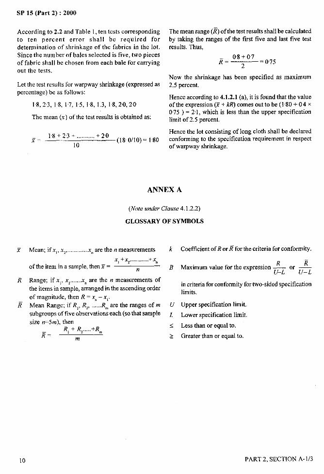
ANNEX A
(Note under Clause 4. 1.2.2)
GLOSSARY OF SYMBOLS
Mean; if x,, x2,.............xn are then measurements k
x, +X2..............+Xn
of the item in a sample, then Y = n B
Range; if xl, X2......,xn are the n measurements of
the items in sample, arranged in the ascending order
of magnitude, then R = x“ – X1.
Mean Range; if R,, Rz, ......R~ are the ranges of m U
subgroups of five observations each (so that sample L
size n=5m), thenR, + R, .....+R~
<
~=m
>
Coefficient of R or ~ for the criteria for conformity.
R EMaximum value for the expression — —
U–L ‘r U–L
in criteria for conformity for two-sided specificationlimits.
Upper specification limit.
Lower specification limit.
Less than or equal to.
Greater than or equal to.
m
I
PART 2, SECTION A- 1/3
I
-—. - .— - -----St’ 15 (l’art 2) : ZWU
SAMPLING OF WOOLEN FABRICS
(Source : IS
1 SCOPE
It prescribes the methods of sampling of woollen fabricsfor determination of various characteristics, namely,mass, breaking load (warp and weft), count of yarn, ends,picks, length, width, relaxation shrinkage, pH value ofaqueous extract, proofing agent, colour fastness, DDTcontent, ether soluble matter and water penetration. Itgives the number of tests for determination of breakingload and mass with specified degree of accuracy. It alsolays down the criteria for ascertaining the conformity tothe specified requirements for the characteristics.
‘2 SAMPLING
2.1 The pieces shall be sampled from each lot for
determination of various characteristics. In order thatpieces selected are representative of the lot, they shallbe suitably distributed over the bales/ cases in the lot.Unless otherwise agreed to between the buyer and theseller, the number of bales/cases to be taken from a lotfor the purpose shall depend upon the size of the lot and
shall be in accordance with Table 1.
2.2 In case the lot is not in the form of bales or cases but
offered as pieces or rolls, the number of pieces or rollsto be selected from the lot for testing shall be equal tothe number of tests required to be carried out accordingto COI2 of Table 2.
Table 1 Number of Bales/Casesto be Chosen from a Lot(Clauses 2.1,3.4 mzd5.1)
No. of Bales/Cases No. of Bales/Cases
In the Lot to be Selected
(1) (2)
2to 15 2
16t050 3
51 to 100 5
101and above 10
2.3 The bales, cases, pieces or rolls shall be selected at
random from the lot. The procedure for sampling shallbe simple random sampling or systematic sampling asgiven in 3.1 and 3.3, respectively of IS 4905:1968
‘Methods for random sampling’.
11191: 1985)
.—
—...
3 NUMBER OF TESTS
3.1 The number of tests to be made for determinationof the characteristics, namely, ends, picks, count of yarn,length, width, relaxation shrinkage, pH value of aqueousextract, proofing agent, colour fastness, DDT ccm@rt,ether soluble matter and water penetration, shall beaccording to Table 2.
Table 2 Number of Tests for Ends, Picks, Count,Length, Width, Relaxation Shrinkage, pH Value ofAqueous Extract, Proofing Agent, Colour Fastness,
DDT Content, Ether Soluble Matter andWater Penetration
(Clauses 2.2, 3.1,3.4 and5.1)
No. of Pieces Number of Tests for
in the Lot ~Count, Ends, Elck,Lengthand Width pH value of Aqueous Extract,
ProofingAgent, Colour Fastness,DDT Content, Ether SolubleMatter and Water Penetration
(1) (2) (3)
up to 150 8 3
151to 500 13 5
501to 1000 20 8
1001 and above 32 8
3.2 Number of tests to be made for determination ofmass and breaking load (warp and weft) shall dependupon the accuracy with which they are to be determined,and are given in Table 3.
Table 3 Number of Tests for Massand Breaking Load
(Clause 3.2)
Characteristic Limit of Error of Mean (Percent)
~
Mass 10 7 5 3Breaking load 20 15 10 5
(Warpand We@
3.2.1 Unless otherwise agreed to between the supplierand the seller, five tests for mass and ten tests for breakingload (warp and wetl) shall be taken for routine testing.
3.3 The number of tests for determination of count ofyarn shall be the same as that for the mass.
(
1,
;\
PART 2, SECTION A-1/4 11
SP 15 (Part 2) :2000
3.4 As far as possible, equal number of pieces or rollsshall be drawn from each selected bale. The number ofpieces or rolls taken from each bale shall be determinedby dividing the number of tests to be conducted (see CO12 of Table 2) by the number of bales selected (seeTable 1).
3.4.1 The number of pieces or rolls for determination
of characteristics other than ends, picks, length and width
shall be drawn from those which are already selected
according to 2.2. The number of pieces or rolls to be
selected shall be the same as number of tests required to
be carried out for the relevant characteristics except
breaking load. In case of breaking load, the number of
pieces or rolls to be selected shall be the same as that for
mass.
4 CRITERIA FOR CONFORMITY
4.1 For ascertaining the conformity of the lot to the
specification requirements for the characteristics given
in 3.2 the procedure given in 4.1.1 and 4.1.2 shall be
adopted. The procedure for determining the conformity
of the lot is illustrated in examples in 5.1.
4.1.1 One-sided Specljicution LimitThe lot shall be declared as conforming to thespecification ifi
a) the value of expression (Y – M?) or (Y – k~) isgreater than or equal to L, when the lowerspecification limit L is given,
b) the value of the exp~~ssion (Z + Id?) or (Y+ k~)is less than or equal to U, when the upperspecification limit U is given,
Where the values of the factor k are given in Table 4 fordifferent sample sizes, and U and L refer to thespecification limits for individual test results.
4.1.2 Two-sided Spec@ation Limit
The lot shall be declared as conforming to the
specification ifi
a) the value of the expression Z?/(U-L) or
~/(U–L) is less than or equal to B,
b) the value of the expression (Y + kl?) or (Z + k~)
is less than or equal to U, and
c) the value of the expression (Z – kR) or (Y– k~)
is greater than or equal to L.
Where the values of the factors B and k are givenTable 4 for different sample sizes, and U and L referthe specification limits for individual test results.
Table 4 Values of the Factors(Clauses 4.1.1 and4. 1.2)
into
Sample Size
;1)35710
15 and above
FactorA
rk B’
(2) (3)0.5 0.90.4 0.90.4 1.00.5 0.8
0.5 0.7
4.2 For ascertaining the conformity of the lot thespecification requirements for the characteristics givenin 3.1, the following criteria for conformity shall beadopted.
4.2.1 The lot shall be declared conforming to therequirements of the specifications if the number of testresults not meeting the requirements as laid down in therelevant specification does not exceed the correspondingacceptance number given in Table 5.
Table 5 Acceptance Numbers
Number of Tests Acceptance Number
(1) (2)
3 0
5 0
8 0
13 1
20 2
32 3
5 ILLUSTRATIVE EXAMPLE
5.1 A consignment of 75 bales of flannel, hospital greywas received by a buyer who wanted to ascertain theconformity of the lot to the requirement of breaking loadfor warp. The material was manufactured and suppliedas per the requirements of IS 674:1987 ‘Flannel,hospital grey’ which specifies a minimum 65 kg ofbreaking load on 15cm x 20cm strip for warp. Thenumber of bales to be chosen from 75 bales accordingto Table 1 is 5.
If 6 percent limit of error of mean is chosen thenaccording to 3.2 and Table 2, 15 tests are to be carriedout. Hence following the procedure given in 3.4(15/5) = 3 pieces or rolls are chosen from each of the
12 PART 2, SECTION A-1/4
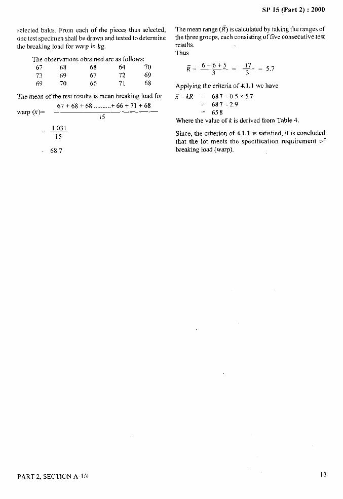
selected bales. From each of the pieces thus selected,one test specimen shall be drawn and tested to determinethe breaking load for warp in kg.
The observations obtained are as follows:67 68 68 64 70
73 69 67 72 69
69 70 66 71 68
The mean of the test results is mean breaking load for
67+ 68+ 68 ..........+ 66 + 71 +68warp (1) =
15
1031——15
= 68.7
SP 15 (Part 2) :2000
The mean range (~) is calculated by taking the ranges ofthe three groups, each consisting of five consecutive testresults. ,Thus
~= 6+6+5 . +
3z 5.7
Applying the criteria of 4.1.1 we have
%–k~ = 687– 0.5 X57
= 687-2.9= 658
Where the value of k is derived from Table 4.
Since, the criterion of 4.1.1 is satisfied, it is concludedthat the lot meets the specification requirement ofbreaking load (warp).
f.,
PART 2, SECTION A- 1/4 13
I
I II
SP 15 (Part 2) :2000
SAMPLING OF MAN-MADE CONTINUOUS
FILAMENT FLAT YARN
[Sxwce: IS 7703 (Part 4) : 1981]
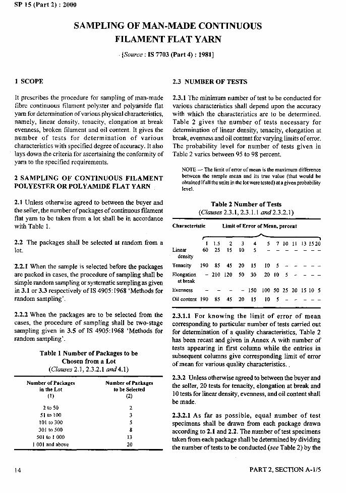
1 SCOPE
It prescribes the procedure for sampling of man-made
fibre continuous filament polyster and polyamide flatyarn for determination of various physical characteristics,namely, linear density, tenacity, elongation at breakevenness, broken filament and oil content. It gives thenumber of tests for determination of variouscharacteristics with specified degree of accuracy. It alsolays down the criteria for ascertaining the conformity ofyam to the specified requirements.
2 SAMPLING OF CONTINUOUS FILAMENTPOLYESTER OR POLYAMIDE FLAT YARN
2.1 Unless otherwise agreed to between the buyer andthe seller, the number of packages of continuous filamentflat yarn to be taken from a lot shall be in accordancewith Table 1.
2.2 The packages shall be selected at random from alot.
2.2.1 When the sample is selected before the packagesare packed in cases, the procedure of sampling shall besimple random sampling or systematic sampling as givenin 3.1 or 3.3 respectively of IS 4905:1968 ‘Methods forrandom sampling’.
2.2.2 When the packages are to be selected from thecases, the procedure of sampling shall be two-stagesampling given in 3.5 of IS 4905:1968 ‘Methods forrandom sampling’.
Table 1 Number of Packages to be
Chosen from a Lot(Clauses 2.1,2 .3.2.1 cmd4.1)
Number of Packages
in the Lot(1)
2 to 5051 to 100101 to300301 to 500
501 to 10001001 and above
Number of Packagesto be Selected
(2)
2358
1320
14
2.3 NUMBER OF TESTS
2.3.1 The minimum number of test to be conducted for
various characteristics shall depend upon the accuracywith which the characteristics are to be determined.Table 2 gives the number of tests necessary fordetermination of linear density, tenacity, elongation atbreak, evenness and oil content for varying limits of error.The probability level for number of tests given inTable 2 varies between 95 to 98 percent.
NOTE— The limit of error of mean is the maximum differencebetween the sample mean and its true value (that would beobtained if all the units in the lot were tested) at a given probabilitylevel.
Table 2 Number of Tests(Clauses 2.3.1,2 .3.1.1 arzd2.3.2.1)
Characteristic Limit of Error of Mean, percent
—.
11.5234 5 7 10 11 131520Lhear 602515105 -–--– --
density
Tenacity 190 85 45 20 15 lo5---–-
Elongation -2101205030 20105 ---–at break
Evenness – - – – 150 100 50 25 20 1510 5
Oil content 190 85 45 20 15 lo5–--––
2.3.1.1 For knowing the limit of error of meancorresponding to particular number of tests carried outfor determination of a quality characteristics, Table 2has been recast and given in Annex A with number oftests appearing in first column while the entries in
subsequent columns give corresponding limit of errorof mean for various quality characteristics. .
2.3.2 Unless otherwise agreed to between the buyer andthe seller, 20 tests for tenacity, elongation at break and10 tests for linear density, evenness, and oil content shallbe made.
2.3.2.1 As far as possible, equal number of testspecimens shall be drawn from each package drawnaccording to 2.1 and 2.2. The number of test specimenstaken from each package shall be determined by dividingthe number of tests to be conducted (see Table 2) by the
PART 2, SECTION A-1/5
I
SP 15 (Part 2) :2000
t
number of packages selected (see Table 1). If it comesout to be a fractional number its maximum integral part
(say i) shall be taken and i or (i + 1) specimen shall betaken from each selected package so as to obtain therequisite number of test specimens. In case the numberof tests are less than the number of packages selected,one or more test specimen may be drawn from eachselected package to get the number of tests specimens orbe an integral multiple of 5. For example, when thereare 501 to 1 000 packages in the lot, 13 packages areselected for testing. According to 2.3.2 for routine testing,the number of tests for tenacity are 20 while they are10 for linear density. For drawing test specimens fortenacity 20 test specimens are to be taken from13 packages. Thus one (maximum integral part of20/13) test specimen is taken out from each of13 packages giving only 13 test specimens. Theremaining 7 (= 20 – 13) test specimen are drawn oneeach from any 7 of the 13 packages. In case of lineardensity, the number of packages drawn (13) is greaterthan the number of test specimens (1 O) required. Henceinstead of testing only 10 test specimens, 15 (the smallestintegral multiple of 5 greater than 13) test specimens aretested. Here one test specimen is drawn from each of the13 packages and the remaining 2 (=1 5–13) test specimensare drawn one each from any two of the 13 packages.
2.3.3 To determine the characteristics broken filament,each package in the sample, selected according to 2.3.2.1shall be visually examined and number of brokenfilament counted.
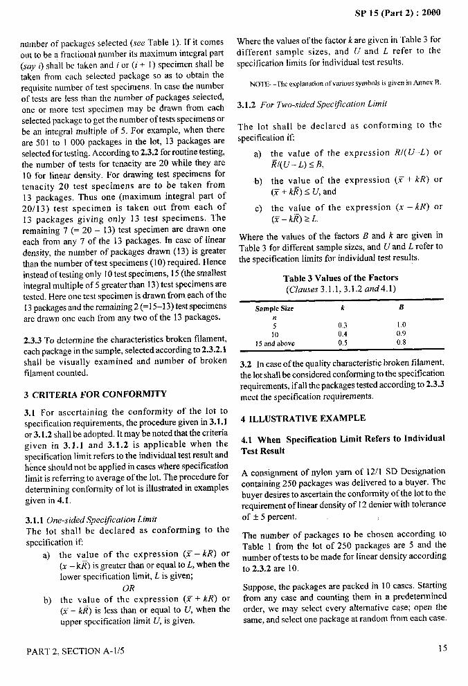
3 CRITERIA FOR CONFORMITY
3.1 For ascertaining the conformity of the lot tospecification requirements, the procedure given in 3.1.1or 3.1.2 shall be adopted. It maybe noted that the criteriagiven in 3.1.1 and 3.1.2 is applicable when thespecification limit refers to the individual test result andhence should not be applied in cases where specificationlimit is referring to average of the lot. The procedure fordetermining conformity of lot is illustrated in examplesgiven in 4.1.
3.1.1 One-sided Spec@ation Limit
The lot shall be declared as conforming to thespecification if
a) the value of the expression (Y– I@ or(Z- k~) is greater than or equal to L, when thelower specification limit, L is given;
OR
b) the value of the expression (Y+ kR) or(F+ k~) is less than or equal to U, when theupper specification limit U, is given.
Where the values of the factor k are given in Table 3 fordifferent sample sizes, and U and L refer to the
specification limits for individual test results. ~
Y,
NOTE—The explanation of various symbols is given in Annex B.!
;. ----?~:
3.1.2 For Two-sided Spec@ation Limit
The lot shall be declared as conforming to the
specification ifi
a) the value of the expression R/( U–L) or~/(U– L) s B,
b) the value of the expression (,Y + kR) or(X+ k~)s U, and
c) the value of the expression (f– kR) or(E - k~) 2 L.
Where the values of the factors B and k are given inTable 3 for different sample sizes, and U and L refer tothe specification limits for individual test results.
Table 3 Values of the Factors
(Clauses 3.1.1,3.1.2 and4.1)
Sample Size k Bn5 0.3 1.010 0.4 0.9
15 and above 0.5 0.8
3.2 In case of the quality characteristic broken filament,the lot shall be considered conforming to the specificationrequirements, if all the packages tested according to 2.3.3meet the specification requirements.
\
4 ILLUSTRATIVE EXAMPLE
4.1 When Specification Limit Refers to IndividualTest Result
A consignment of nylon yarn of 12/1 SD Designationcontaining 250 packages was delivered to a buyer. Thebuyer desires to ascertain the conformity of the lot to therequirement of linear density of 12 denier with toieranceof f 5 percent.
The number of packages to be chosen according toTable 1 from the lot of 250 packages are 5 and thenumber of tests to be made for linear density according
to 2.3.2 are 10.
Suppose, the packages are packed in 10 cases. Startingfrom any case and counting them in a predeterminedorder, we may select every alternative case; open thesame, and select one package at random from each case.
PART 2, SECTION A-1/5 15
/
I},
SP 15 (Part 2) :2000
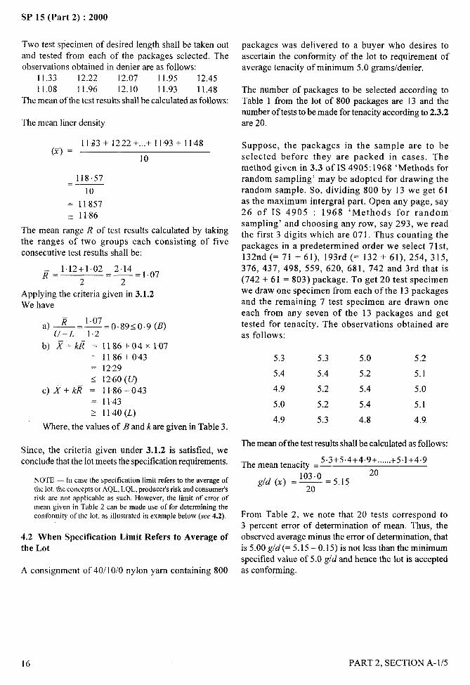
Two test specimen of desired length shall be taken out packages was delivered to a buyer who desires toand tested from each of the packages selected. The ascertain the conformity of the lot to requirement ofobservations obtained in denier are as follows: average tenacity of minimum 5.0 grams/denier.
11.33 12.22 12.07 11.95 12.4511.08 11.96 12.10 11.93 11.48 The number of packages to be selected according to
The mean of the test results shall be calculated as follows: Table 1 from the lot of 800 packages are 13 and thenumber of tests to be made for tenacity according to 2.3.2
The mean liner density are 20.
1133 +1222 +...+ 1193+1148(y) =
10
118.57._—10
= 11857~ 1186
The mean range ~ of test results calculated by takingthe ranges of two groups each consisting of fiveconsecutive test results shall be:
1.12+1.02 2.14~= —=1.072=2
Applying the criteria given in 3.1.2We have
—1.07
a)~=—U-L 1.2
=0.89< 0.9 (B)
b) ~+k~ =I186+O4X1O7
= 1186+043
Suppose, the packages in the sample are to beselected before they are packed in cases. Themethod given in 3.3 of IS 4905:1968 ‘Methods forrandom sampling’ may be adopted for drawing therandom sample. So, dividing 800 by 13 we get 61as the maximum intergral part. Open any page, say26 of IS 4905 : 1968 ‘Methods for randomsampling’ and choosing any row, say 293, we readthe first 3 digits which are 071. Thus counting thepackages in a predetermined order we select 7 1st,132nd (= 71 +61), 193rd (= 132 + 61), 254, 315,376, 437, 498, 559, 620, 681, 742 and 3rd that is(742 +61 = 803) package. To get 20 test specimenwe draw one specimen from each of the 13 packagesand the remaining 7 test specimen are drawn oneeach from any seven of the 13 packages and gettested for tenacity. The observations obtained areas follows:
5.3 5.3 5.0 5.2= 1229< 1260 (U)
5.4 5.4 5.2 5.1
C)~+k~ = 1186–043 4.9 5.2 5.4 5.0
= 1143 5.0 5.2 5.4 5.12 1140(L)
4.9 5.3 4.8 4.9Where, the values of B and k are given in Table 3.
Since, the criteria given under 3.1.2 is satisfied, weThe mean of the test results shall be calculated as follows:
conclude that the lot meets the specification requirements. The mean tenacitv =5.3+5 .4+4.9 + ......+5.1+4.9
.20
NOTE— in case the specificationlimit refersto the averageof g/d (Y) = y=5.15the lot, the concepts or AQL,LQL,producer’sriskandconsumetsrisk are not applicable as such. However, the limit of error ofmean given in Tab]e 2 can be made use of for determining theconformity ot’the lot, as illustrated in example below (see 4.2). From Table 2, we note that 20 tests correspond to
3 percent error of determination of mean. Thus, the
4.2 When Specification Limit Refers to Average of observed average minus the error of determination, that
the Lot is 5.00 g/d(= 5.15 – 0.15) is not less than the minimum
specified value of 5.0 gld and hence the lot is accepted
A consignment of 40/10/0 nylon yarn containing 800 as conforming.
!,
!
16 PART 2, SECTION A- 1/5
SP 15 (Part 2) :2000
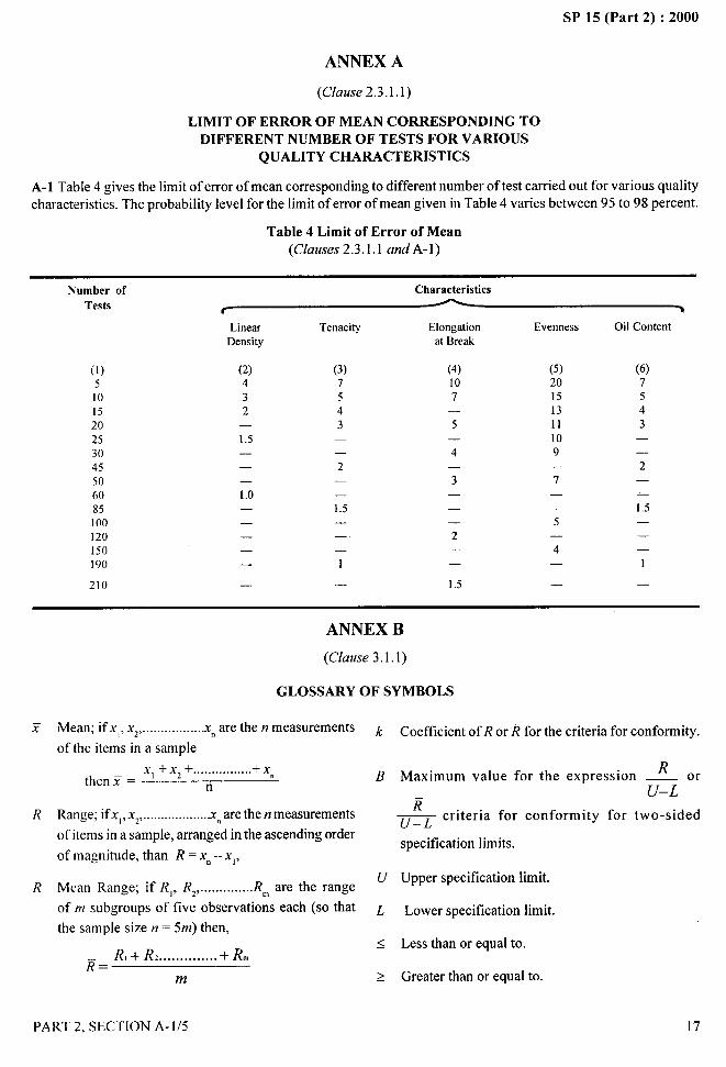
ANNEX A
(Chzuse2.3.l.1)
LIMIT OF ERROR OF MEAN CORRESPONDING TODIFFERENT NUMBER OF TESTS FOR VARIOUS
QUALITY CHARACTERISTICS
A-1 Table 4 gives the limit of error of mean corresponding to different number of test carried out for various quality
characteristics. The probability level for the limit of error of mean given in Table 4 varies between 95 to 98 percent.
Table 4 Limit of Error of Mean(Clauses 2.3.1.1 andA-1)
Number of
Tests
Characteristics
LhearDensity
Tenacity Elongationat Break
Evenness Oil Content
(2)432
(3)7543
(4)107
.
5—
4—
3—
(5)20151311109
(6)7
(1)5101520253045506085100120150190
210
543
1.5—
——2 2— —
7.1.0—
——1.5——
—1.5
—— —
5— .2
——
—4—
1—— 1—
1.5— —
ANNEX B
(Clause 3.1.1)
GLOSSARY OF SYMBOLS
Mean; ifx,, Xz,.................xmare the rzmeasurements k
of the items in a sample
x, +X*+ ................+Xthen Y =
n Bn
Range; ifx,, xz,...................xnare the rrmeasurements
of items in a sample, arranged in the ascending order
of magnitude, than R = Xn–xl,
Mean Range; if R), Rz, ...... ........R~ are the rangeu
Coefficient of R or ~ for the criteria for conformity.
RMaximum value for the expression _ or
U–L—& criteria for conformity for two-sided
specification limits.
Upper specification limit.
Lower specification limit.
Less than or equal to.
Greater than or equal to.
17
of m subgroups of five observations each (so that L
the sample size n = 5m) then,<
~= R,+ R, ..............+Rm
m >
PART 2, SECTION A-1/5
,. . 6,—
SP 15 (Part 2) :2000
PREPARATION OF TEST SPECIMENS FROM
FABRIC SAMPLES FOR PHYSICAL TESTS
(Source : IS 6668: 1972)
1 SCOPE
1.1 It prescribes procedure for preparing test specimensfrom fabric samples for the purpose of testing various
physical characteristics.
1.1.1 This standard is applicable to all types of fabrics,namely, woven, knitted, feked and nonwoven, made fromany type of fibre.
2 PROCEDURE
2.1 Woven Fabrics
2.1.1 Take one of the test samples drawn for the purpose
of preparing test specimens, I lark the warp and weftdirection and lay it flat on the surface of smooth table.Remove any wrinkles or folds in the sample by handwithout unduly stretching it.
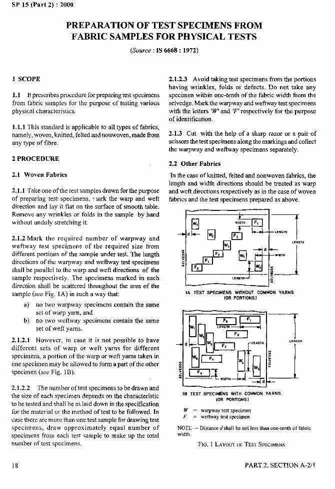
2.1.2 Mark the required number of warpway andweftway test specimens of the required size fromdifferent portions of the sample under test. The lengthdirections of the warpway and wetlway test specimensshall be parallel to the warp and weft directions of thesample respectively. The specimens marked in eachdirection shall be scattered throughout the area of thesample (see Fig. 1A) in such a way that:
a) no two warpway specimens contain the sameset of warp yam, and
b) no two we ftway specimens contain the sameset of weft yarns.
2.1.2.1 However, in case it is not possible to have
different sets of warp or weft yarns for differentspecimens, a portion of the warp or weft yarns taken inone specimen may be allowed to form a part of the otherspecimen (see Fig. lB).
2.1.2.2 The number of test specimens to be drawn andthe size of each specimen depends on the characteristicto be tested and shall be as laid down in the specificationfor the material or the method of test to be followed. Incase there are more than one test sample for drawing testspecimens, draw approximately equal number ofspecimens from each test sample to make up the totalnumber of test specimens.
2.1.2.3 Avoid taking test specimens from the portionshaving wrinkles, folds or defects. Do not take anyspecimen within one-tenth of the fabric width from theselvedge. Mark the warpway and wefhvay test specimenswith the letters ‘W’and ‘F’ respectively for the purpose
of identification.
2.1.3 Cut with the help of a sharp razor or a pair ofscissors the test specimens along the markings and collectthe warpway and we ftway specimens separately.
2.2 Other Fabrics
In the case of knitted, felted and nonwoven fabrics, thelength and width directions should be treated as warpand weft directions respectively as in the case of wovenfabrics and the test specimens prepared as above.
I 1
c1 “pm“ ‘% id-J LENGTH
I
1 &
4
5
b.9 —
d
—
!fl:
1A TEST SPECIMENS WITHOUT COMMON YARNS(ORPORTIONS}
mI I
lB TEST SPECIMENS WITH COMMON YARNS(OR PORTIONS )
W = warpway test specimenF = weftway test specimen
NOTE— Distanced shall be not less than one-tenth of fabricwidth.
FIG. 1 LAYOUTOFTESTSPECIMENS
-... -A
——
18 PART 2, SECTION A-2/l
SP 15 (Part 2) :2000-.. ..—
METHODS FOR
PREPARATION OF LABORATORY TEST
SAMPLES AND TEST SPECIMENS OF TEXTILE
MATERIALS FOR CHEMICAL TESTING
(Source : IS 9022: 1979)
This standard prescribes the methods in which thelaboratory test samples are obtained by the combination
of numerous small portions each drawn from a differentpart of the laboratory bulk sample. Therefore, any resultsobtained on test specimens from these samples willestimate the mean level in the laboratory bulk samplebut will not indicate the variability of level from portionto portion of the laboratory bulk sample. Consequentlyit is appropriate to use this method in cases where it isdesired to estimate the bulk composition, for example,the proportions of different fibres in a blend, but it is notappropriate in cases where variability is important, forexample, in the determination ofpH where the local valueis significan~ or in the determination of fimgicides, wherea high value in one area of the material does notcompensate for low value elsewhere. Also, it may notbe appropriate for use in determination of commercialmass values.
1 SCOPE
1.1 This method specifies procedure for laboratory testsamples of textile materials from laborato~ bulk samples
taken from a bulk source and gives general directionsfor the preparation of test specimens of convenient sizefor chemical tests.
1.2 No provision for sampling from the bulk source isdescribed since it is assumed that the laboratory bulksample has been selected by a suitable procedure and isrepresentative of the bulk source.
2 DEFINITIONS
For the purpose of this method, the following definitionsshall apply.
2.1 Bulk Source
That quantity of material which is to be judged on thebasis of one series of test results. This may comprise,for example, all the material in one delivery of cloth; allthe cloth woven from a particular beam; a consignmentof yarn; a bale or a group of bales of raw fibre.
PART 2, SECTION A-2/2
2.2 Laboratory Bulk Sample
That portion of the bulk source taken to be representativeof the whole. The size and nature of the laboratory bulksample should be sufficient to overcome adequately thevariability of the bulk source and to facilitate ease ofhandling in the laboratory.
2.3 Laboratory Test Sample
That portion of the laboratory bulk sample from whichspecimens are taken for testing. The size and nature ofthe laboratory test sample should be sufficient toovercome adequately the variability of the laboratorybulk sample.
2.4 Test Specimen
The portion of material required to give an individualtest result.
3 PRINCIPLE
The laboratory test sample is taken so that it isrepresentative of the laboratory bulk sample. The testspecimens are taken tiom the laboratory test sample insuch a way that each of them is representative of thelaboratory test sample.
4 SAMPLING OF LOOSE FIBRES
4.1 Non-oriented Flbres
4.1.1 If the laboratory bulk sample consists of less than
5 kg of loose tibre, spread it out in an even layer. Obtainthe laboratory test sample by taking at random aminimum of 100 tufts of approximately equal size, thetotal mass being sufficient to give a laboratory test sampleof required size.
4.1.2 If the laboratory bulk sample is greater than 5 kg,divide it into a number of equal portions, and take anequal number of tufts of suitable mass from each portionsuch that the total number from all portions exceed 100.
19

SP 15 (Part 2) :2000
4.1.3 Pretreat the laboratory test sample, if required, bythe test method to be used. From the laboratory testsample remove at random, using forceps, small tutls ofapproximately equal mass to give a test specimen of themass required.
4.2 Oriented Fibres (Card Webs, Slivers, Rovings)
From randomly selected parts of the laboratory bulksample cut not less than ten cross sections each weighingapproximately 1 g. After applying pretreatment, ifnecessary, lay the crosssections together and obtain thetest specimen by cutting through them so as to take aportion of each of the ten lengths.
5 SAMPLING OF YARN
5.1 Yarn in Packages or in Hanks
5.1.1 If the number of packages in the laboratory bulksample is 25 or less, sample all the packages. If thenumber exceeds 25, take 25 packages at random. If thelinear density of the yam, expressed in tex, is t,and thenumber of packag”es taken from the laboratory bulksample is n, the length of yam from each package togive a 10 g laboratory test sample is:
10’ cm
nxt
if n x t is high, for example, more than 2000, wind aheavier skein and cut it across in two places to make atow of suitable mass.
5.1.2 Withdraw the appropriate continuous lengthfrom each package either by winding skeins of thesame number of turns on a warp reel (see Note) orby some other means. Unite the length side by sideeither as a single skein or as a tow to form thelaboratory test sample, ensuring that there are equallengths from each package in the skein or tow.Pretreat the laboratory test sample, if required, by a
suitable method and ensure that the ends of anysample in the form of tow are securely tied beforetreatment.
NOTE — If the packages can be mounted in a convenient creel asufficient number of skeins can be wound simultaneously.
5.1.3 Take specimens of the appropriate mass fromthe laboratory test sample by cutting a bunch ofthreads of equal length from the skein or tow andcomprising all the threads in it, ensuring that testspecimens are taken from a place remote from thetie bands.
5.2 Yarn on Warp
5.2.1 Take the laboratory test sample by cutting alength from the end of the warp, not less than 20 cm
long and comprising all the yarns in the warp except
the selvedge yarns, which are rejected. Tie the bunch
of threads together near one end. If the sample is too
large for any required pretreatment, divide it into two
or more portions, each portion tied together separately
for pretreatme,nt. Reunite the portions after the
pretreatment.
5.2.2 Take a test specimen by cutting a suitable length
ti-om the laboratory test sample from the end remote from
the tie band, and comprising all the threads in the warp.
For warp of N threads of tex t,the length of a specimen
of mass 1 g is:
lo,
Nxt cm
6 SAMPLING OF FABRIC
6.1 From a Laboratory Bulk Sample Consisting of a
Single Cutting up to 1 m in Length
6.1.1 Cut a diagonal trip from corner to corner and
remove the selvedges. For a laboratory test sample of
Xg the area of the strip required is:
Xxlo’
Mcm’
where M is the mass of the cloth in grams per square
metre.
6.1.2 This area divided by the length of the diagonal in
centimeters will give the required width of strip in
centimeters.
6.1.3 After subjecting the strip to any pretreatment, cut
it across its length into four equal lengths and
superimpose them. Take test specimens from any part
of the layered material by cutting through all the layers
in such a way that each specimen comprises an equal
length from each layer.
6.2 From a Laboratory Bulk Sample Consisting of a
Single Cutting More than 1 m in Length
Take two fidl-width cuttings, one from each end of the
laboratory bulk sample and not more than 1 m long. Cut
20 PART 2, SECTION A-2/2
both into two equal portions by a cut parallel to the warp
direction and mark the right-hand and left-hand halves
of each. Put the right-hand half of one cutting to the left-
hand half of the other, with the cut edges together, and
cut a diagonal strip from the lower corner of one cutting
to the upper comer of the other, after removing the
selvedges. Proceed as in 6.1, treating the two half-width
diagonal strips as if they were a full-width continuous
strip.
6.3 From a Laboratory Bulk Sample Consisting ofSeveral Cuttings
Treat each cutting separately as described in 6.1 or 6.2and give results for each cutting in the test report.
6.4 From a Fabric with a Design Arising from theDistribution of Threads
6.4.1 Ensure, if possible, that there is an integralnumber of complete repeats of the design in thelaboratory bulk sample and proceed as in 6.1 unlessthe laboratory bulk sample so obtained is more than1 m in length in which case proceed as in 6.2. Wherethe pattern repeat is large and/ or asymmetric, theentire strip should be cut into small fragments,thoroughly mixed and then sampled by the procedureindicated in 4.1.
SP 15 (Part 2) :2000
6.4.2 Where the laboratory bulk sample does notcontain at least on complete repeat of the design, reportthis under 8.1 (b).
7 SAMPLING OF MADE-UP ARTICLES+
i,.-+,..I‘i{
7.1 The laboratory bulk sample normally consists of acomplete made-up article or a representative part of suchan article.
7.2 Determine whether all parts of the article are ofsimilar composition; if so, treat the whole article as alaboratory bulk sample, and take a laboratory testsample representative of the laboratory bulk sample.
7.3 If parts of the article are of different composition,separate the parts and treat each as the laboratory bulksample and take a laboratory test sample representativeof the laboratory bulk sample.
8 TEST REPORT
8.1 The test report shallinformation:
nclude the following
a) A statement that the material was sampled inaccordance with this method,
b) The size of the laboratory bulk sample (see also
6.4.2),
c) The size of the laboratory test sample, andd) The size of the test specimen.
/
PART 2, SECTION A-2/2,
21
I IIi!!
I

As in the Original Standard, this Page is Intentionally Left Blank
SP 15 (Part 2) :2000
.-1
““,,!
SECTION B
PHYSICAL TESTS

As in the Original Standard, this Page is Intentionally Left Blank
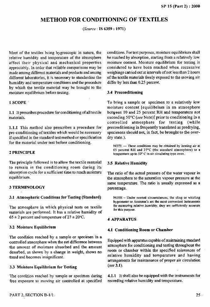
SP 15 (Part 2) :2000
METHOD FOR CONDITIONING OF TEXTILES
(Source : IS 6359: 1971)
‘!.. ....-*.
‘,
Most of the textiles being hydroscopic in nature, therelative humidity and temperature of the atmosphereaffect their physical and mechanical propertiesappreciably. In order that reliable comparisons may bemade among different materials and products and amongdifferent laboratories, it is necessary to standardize thehumidity and temperature conditions and the procedureby which the textile material may be brought to themoisture equilibrium before testing.
1 SCOPE
1.1 It prescribes procedure for conditioning of all textile
materials.
1.1.1 This method also prescribes a procedure for
pre-conditioning of textiles which would be necessaryif specified in the standard test method or specificationfor the material under test before conditioning.
2 PRINCIPLE
The principle followed is to allow the textile materialto remain in the conditioning room during itsabsorption cycle for a sufficient time to reach moistureequilibrium.
3 TERMINOLOGY
3.1 Atmospheric Conditions for Testing (Standard)
The atmosphere in which physical tests on textilematerials are performed. It has a relative humidity of65* 2 percent and temperature of 27 ● 20”C.
3.2 Moisture Equilibrium
The condition reached by a sample or specimen in acontrolled atmosphere when the net difference betweenthe amount of moisture absorbed and the amount
desorbed, as shown by a change in weight, shows notrend and becomes insignificant.
3.3 Moisture Equilibrium for Testing
fThe condition reached by sample or specimen during,
(free exposure to moving.
iPART 2, SECTION B-l/l
air controlled at specified
conditions. For test purposes, moisture equilibrium shallbe reached by absorption, starting from a relatively lowmoisture content. Moisture equilibrium for testing isconsidered to have been reached when successiveweighings carried out at intervals of not less than 2 hoursof the textile materials freely exposed to the moving airdiffer by less than 0.25 percent.
3.4 Preconditioning
To bring a sample or specimen to a relatively lowmoisture content [equilibrium in an atmospherebetween 10 and 25 percent RH and temperature notexceeding 50°C (see Note)] prior to conditioning in acontrolled atmosphere for testing (whilepreconditioning in frequently translated as predrying,specimens should not, in fact, be brought to the over-dry state.).
NOTE — These conditions may be obtained by heating air at65 percent RH and 27°C (the standard atmosphere) to atemperatureup to 50” C in air circulating type oven.
3.5 Relative Humidity
The ratio of the actual pressure of the water vapour inthe atmosphere to the saturation vapour pressure at thesame temperature. The ratio is usually expressed as apercentage.
4
NOTE - Under normal circumstances, the sling or whirlinghygrometer or Assmann’s are the most convenient instrumentsfor measuring relative humidity, they are sufficiently accuratefor this purpose.
APPARATUS
4.1 Conditioning Room or Chamber
Equipped with apparatus capable of maintaining standardatmosphere for conditioning and testing throughout theroom or chamber within the specified tolerances ofrelative humidity and temperature and havingarrangements for maintenance of proper air circulation(see 3.1).
4.1.1 It shall also be equipped with the instruments forrecording relative humidity and temperature.
25
,,
II
I
I
/
SP 15 (Part 2) :2000I-. -- . -
4.2 Preconditioning Cabinet or Room
Equipped with apparatus capable of maintainingatmosphere for pre-conditioning of textiles throughoutthe room or chamber within the specified tolerances ofrelative humidity and temperature (see 3.4).
4.3 Balance
Capable of weighing to an accuracy of 0.25 percent.
5.2 Expose the specimen or sample in the atmosphere forpreconditioning in such a way as to expose, as far as
possible, all portions of the material to the atmosphere untilthe moisture equilibrium is attained (see Note 1under 5.3).
5.3 Expose the specimen or sample (already pre-conditioned, if so required) in the standard atmospherein such a way as to expose, as far as possible, all portions
of the material to the atmosphere until the moistureequilibrium is attained (see Notes).
5 PROCEDURENOTES
5.1 Determine the relative humidity and temperature ofthe conditioning room or chamber (see 4.1) and, ifpreconditioning is also to be carried out, find the relativehumidity and temperature of the preconditioning cabinet
or room to check whether the conditions meet thespecified values of relative humidity and temperature ornot. If the conditions are not as required, makeadjustments to bring them to the desired limits oftemperature and humidity.
5.1.1 If both preconditioning and conditioning areprescribed in the test method or the specification for thematerial, proceed as gives in 5.2 and 5.3, and if onlyconditioning has been prescribed, omit 5.2.
I In case the material received is in package form, it ispreferable to prepare test specimens in loose or open formso that all portions get uniformly exposed to thepreconditioning or conditioning atmospheres. For example,in case of yarn in the form of cones or cheeses, suitableskeins may be prepared for conditioning,
2 For guidance purposes, it may be noted that the minimumtime required for the various types of textile materials havingmoisture regain values of less than 5 percent is about 6 hours toreach moisture equilibrium while forthose having moisture regainvalues of more than 5 percent it is 24 hours.
5.4 The textile materials conditioned as above be testedaccording to the procedure laid down.
k. ..—!4,, .- --
26 PART 2, SECTION B- 1/1
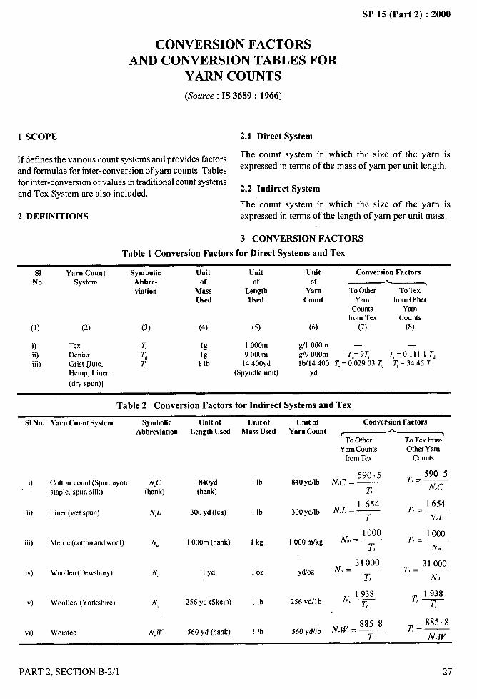
SP 15 (Part 2) :2000.. ..-—
CONVERSION FACTORS
AND CONVERSION TABLES FOR
YARN COUNTS
(Source: IS 3689: 1966)
1 SCOPE
If defmesthe various count systems and provides factorsand formulae for inter-conversion of yam counts. Tablesfor inter-conversion of values in traditional count systemsand Tex System are also included.
2 DEFINITIONS
2.1 Direct System
The count system in which the size of the yarn is
expressed in terms of the mass of yam per unit length.
2.2 Indirect System
The count system in which the size of the yarn isexpressed in terms of the length of yam per unit mass.
3 CONVERSION FACTORS
Table 1 Conversion Factors for Direct Systems and Tex
SI Yarn Count Symbolic Unit Unit Ursit Conversion FactorsNo. System Abbre- Of of of Ac
viation Mass Length Yam To Other To TexUsed Used Count Yarn fmm OtJrer
Counts Yarnfrom Tex
(1)Counts
(2) (3) (4) (5) (6) (7) (8)
O Tex q lg 1000m g/1 000m — —
ii) Denier T, lg 9000m g/9 OOOm Td=9~ ~=O.llll T,iii) Grist [Jute, q 1 lb 14400yd lb/14 400 ~ = 0.02903 ~ ~ = 34.45 ~
Hemp, Linen (Spyndle unit) yd(dry spun)]
Table 2 Conversion Factors for Indirect Systems and Tex
S1No. Yarn Count System Symbolic Unit of Unit oft.,[Init of Conversion Factors :’
ii)
iii)
iv)
v)
vi)
Cotton count (Spunrayonstaple, spun silk)
Liner (wet spun)
Metric (cotton and wool)
Woollen(Dewsbury)
Woollen (Yorkshire)
Worsted
Abbreviation Length Used Mass Used
N<,C 840yd 1lb(hank) (hank)
N,L 300yd (lea) 1 lb
NW, 10OOm(hank) 1 kg
N, 1yd 1Oz
N 256 yd (Skein)y 1 lb
N<,W 560 yd (hank) 1 lb
Yarn Count ~
Yarn Counts Other YarnfromTex Counts
590.5 ~= 590.5840yMb lY’cC = —
z N.C
NL=l.654 1654300yd/lb . — T,=—
T1 N.L
1000N., = —
10001000 01/kg T,=—
27 N.,
31000N,, = —
31000ydoz T,=—
z N,,
N 1938256 ydllb —“ T,
560 yd/lb NW==z
r I 938‘~
885.8Tl=—
N,.w
PART 2, SECTION B-2/l 27
/I
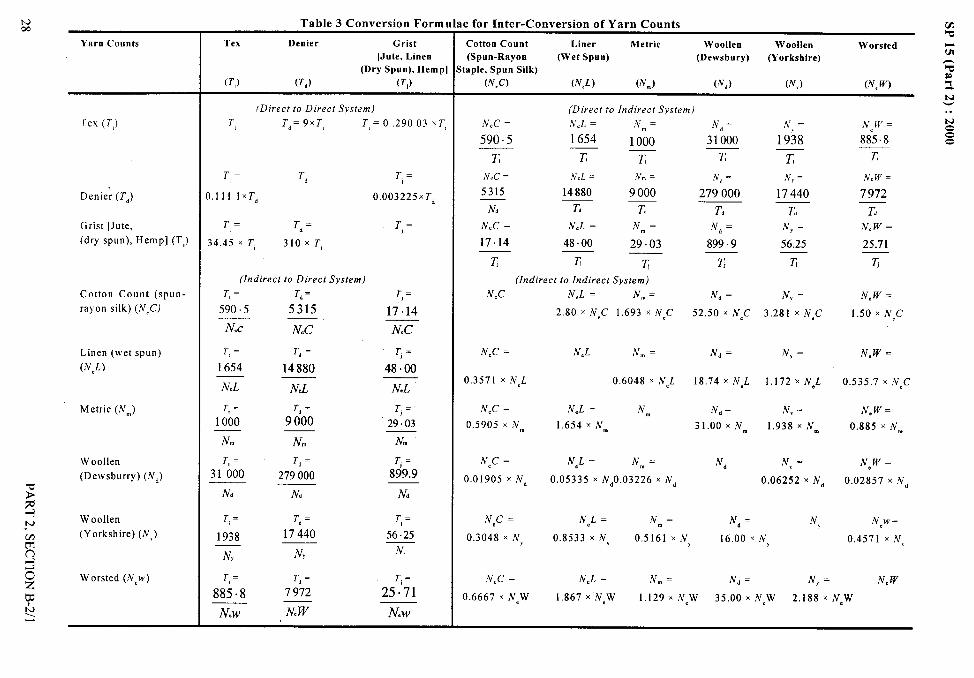
Table 3 Conversion FormlNcm
Yarn Counts
Ie for Inter-Conversion of Yarn Counts ‘mw
Cotton Count Liner Metric Woollen Woollen Worsted w
(Spun-Rayon (Wet Spun) (Dewsbury) (Yorkshire)m
taple, Spun Silk) ~
(N,C) (N,L) (Nm) (Nd) (N,) (N, W) ~
N
Tex Denier Grist
[Jute, Linen(Dry Spun), Hemp]
(TJ (Td) (T,)
(Direct toIndirect System)(Direct to Direct System)T, Td=9x T T,= O.29003 xT,Iex (T,) ‘yd = .$,,=
31000 1938
r T!
N, = .~,=
279000 17440
T, T,,Vd= N, =
899.9 56.25
z z
‘v~ = N, =
52.50 x NCC 3.281 x NCC
Nd = N, =
18.74 x NJ 1.172 xN~L
‘v~= N, =
31.00 x ,Vm 1.938 x ,Vm
N, N\ =
0.06252 x N,
N, = N,
590 ~5 1654 1000
T! K K 27
New=
7972
T,= T, T, =
11 lxTd 0.003225x T,
N.C = ,j:cL = ~m.
5315 14880 9000
N, T, T,Denie; (Td)
T,N, w =
25.71
z
‘v, w =
1.50 x N,c
‘v.w =
0.535.7 x ‘vec
N, w =
0.885 x ,Vm
New =
0.02857 XN~
New=
0.4571 x N\
‘v.w
Grist [Jute,(dry spun), Hemp] (T,)
T,= T,= T,=
.45 x T 31OXT,
Nec == N.L = ‘vm=
17.14 48.00 29.03
z K z
(Indirect to Indirect System)(Indirect to Direct System)T,E T,cCotton Count (spun-
rayon silk) (,VCC)
T,=
17.14
Nec
‘vec =
0.3571 x NeL
N,c =
0.5905 x ,Vm
N*C =
0.01905 x ‘vd
Nec =
0.3048 x N,
Nec ==
0.6667 x N,W
NeL = N.=
2.80 x NCC 1.693 x N,C
NeL N“, =
0.6048 XNCL
N,L = Nm
1.654 x ,Vm
NCL= ‘Vm=
0.05335 x N~O.03226 XN~
NeL = ,Vm=
590 5 5315
N.c N.C N.C
T,= T, =
1654 14880
N.L N.L
T,=
48.00
Linen (wet spun)(N,L)
NeL
Metric (Nm) T, = T, =
000 9000Ti=
29.03
N. N.
T, = T, =I 000 279000
N, N,
N.
Woollen(Dewsburry) (iV,)
$
T}=899.9
N,
hN Woollen.VY (Yorkshire) (,V,)mn
r, = T, = r,=
56.25
N
174401938
N, N,
0.8533 XN, 0.5161 X N, 16.00 XN,
NeL = N. = .v~ = ‘v, =~oz
Worsted (NCW)
wb
T,= T, =
85.8 7972
N.w N. W
Ti=
25.71 1.867 x N,W 1.129 X N,W 35.00 x New 2.188 X NgW
New
-.

SP 15 (Part 2) :2000
Table 4 Cotton Count (Spun-Rayon Staple, Spun Silk) (N,C’)
to Tex (Z’,)
Tex =590.5
Cotton Count
CottonCount o 1 2 3 4 5 6 7 8 9
Tex
65.631.120.415.112.1
10.0
8.567.486.645.96
5.42
4.96
l-ex Tex Tex Tex Tex Tex Tex Tex Tex
o 0 590.5 295.3 196.8 147.6 118.1 98.4 84.4 73.810 59.0 53.7 49.2 45,4 42.2 39.9 36.9 34.7 32.820 29.5 28.1 26,8 25.7 24.6 23.6 22.7 21.9 21.130 19.7 19.0 18.4 17.9 17.4 16.9 16.4 16.0 15.540 14.8 14.4 14.1 13.7 13.4 13.1 12.8 12.6 12.3
11.8 11.6 11,4 11.1 10,9 10,7 10.5 10.4 10.250
9.84 9.68 9.52 9.37 9.23 9.09 8.95 8.81 8.688.44 8.32 8.20 8.09 7.98 7.87 7.77 7.67 7.577.38 7.29 7.20 7.11 7.03 6.95 6.87 6.79 6.716.56 6.49 6.42 6.35 6.28 6.22 6.15 6.09 6.03
60708090
5.91 5.85 5.79 5.73 5.68 5.62 5.57 5.52 5.47100
5.37 5.32 5.27 5.23 5.18 5.14 5.09 5.05 5.00
4.92110
120
Table 5 Denier (T,) to Tex (7’,)
Tex = 0.111 I x Denier
----Denier 0 1 2 3 4 5 6 7 8 9
\Tex
0.8892.003.114.225.33
6.44
7.568.679.78
10.9
Tex
1.002.113.224.335.44
6.56
7.678.789.89
11.0
Tex Tex Tex Tex Tex Tex Tex Tex
0.111 0.222 0.333 0.4441.22 1.33 1.44 1.562.33 2.44 2.56 2.673.44 3.56 3.67 3.784.56 4,67 4.78 4,89
0.556 0.667 0.7781.67 1.78 1.892.78 2.89 3.003.89 4.00 4,115.00 5.11 5.22
0 010 1.1120 2.2230 3.3340 4.44
5.67 5.78 5,89 6.00 6.11 6.22 6.3350 5.56
6.78 6.89 7.00 7.117.89 8.00 8.11 8.229.00 9.11 9,22 9.33
10.1 10.2 10.3 10.4
7.22 7.33 7.448.33 8.44 8.569.44 9.56 9.67
10.6 10.7 10.8
60 6.6770 7.7880 8.8990 10.0
100 11.1 ,,
PART 2, SECTION B-2/1
/
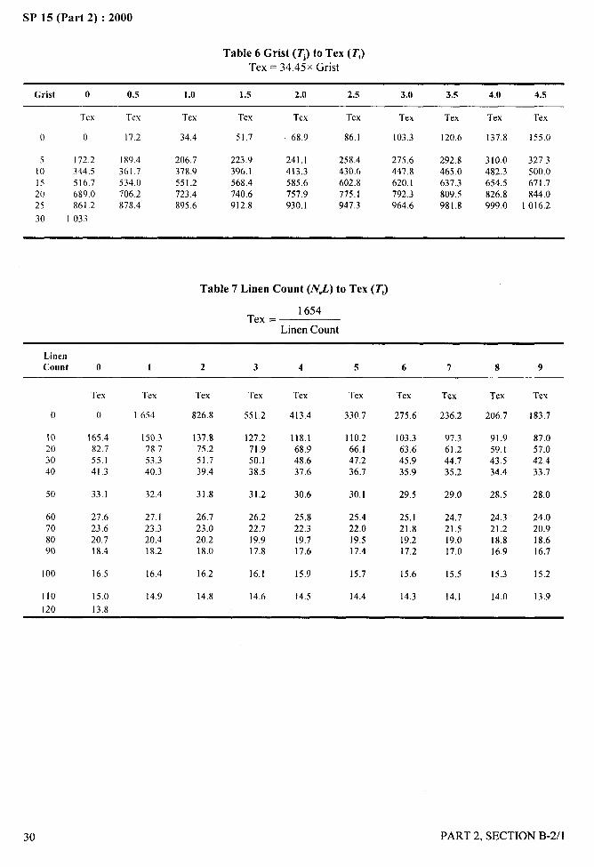
SP 15 (Part 2) :2000
Table 6 Grist (TJ to Tex (7’,)Tex = 34.45x Grist
Grist o 0.5 1.0 1.5 2.0 2.5 3.0 3.5 4.0 4.5
Tex Tex Tex Tex Tex Tex Tex Tex Tex Tex
() () 17.2 34.4 51.7 68,9 86.1 103,3 120.6 137.8 155.0
5 172.2 I89.4 206.7 223.9 241,1 258.4 275,6 292.8 310.0 327.310 344.5 361.7 378.9 396.1 413,3 430.6 447.8 465.0 482,3 500.015 516.7 534.0 551.2 568.4 585,6 602.8 620,1 637.3 654.5 671.720 689.0 706.2 723.4 740.6 757.9 775.1 792,3 809.5 826.8 844.025 861.2 878.4 895.6 912.8 930.1 947.3 964.6 981.8 999.0 1016.230 I 033
Table 7 Linen Count (NJ.) to Tex (Z’,)
1654Tex =
Linen Count
LinenCount o 1 2 3 4 5 6 7 8 9
Tex Tex Tex Tex Tex Tex Tex Tex Tex Tex
o 0 1654 826.8 551.2 413.4 330.7 275.6 236,2 206.7 183.7
10 165.4 150.3 137.8 127.2 118.1 110.2 103.3 97.3 91.9 87.020 82.7 78.7 75.2 71.9 68.9 66.1 63.6 61.2 59.1 57.030 55.1 53.3 51.7 50.1 48.6 47.2 45.9 44.7 43.5 42,440 41.3 40.3 39,4 38.5 37.6 36.7 35.9 35,2 34.4 33.7
50 33.1 32.4 31.8 31.2 30.6 30.1 29.5 29.0 28.5 28.0
60 27.6 27.1 26.7 26.2 25,8 25.4 25.1 24.7 24.3 24.070 23,6 23.3 23.0 22.7 22.3 22.0 21.8 21.5 21.2 20.980 20.7 20.4 20.2 19.9 19.7 19,5 19.2 19,0 18.8 18.690 18,4 18.2 18.0 17.8 17,6 17.4 17,2 17.0 16.9 16.7
I00 16,5 16.4 16,2 16.I 15.9 15.7 15.6 15.5 15.3 15.2
110 15.0 14.9 14.8 14.6 14.5 14.4 14.3 14.1 14.0 13.9120 13.8
___.-c
30 PART 2, SECTION B-2/l
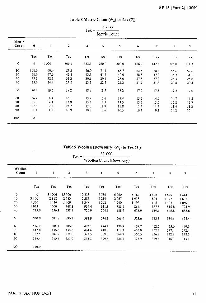
—SP 15 (Part 2) :2000
Table 8 Metric Count (NJ to Tex (Tt)
1000$
Tex =q
Metric Count
“A
..~:. -.!
Metric.,
Count o 17
2 3 4 5 6 7 8 9 .4
Tex Tex Tex Tex Tex Tex Tex Tex Tex Tex
o 0 1000 500.0 333.3 250.0 200.0 166,7 142.8 125.0 111.1
10 100.0 90.9 83.3 76.9 71.4 66.7 62.520
58.8 55.650.0
52.647.6 45.4 43.5 41,7 40.0 38.5 37.0 35.7 34.5
30 33.3 32.3 31.2 30.3 29.4 28.6 27.8 27.0 26.3 25.640 25.0 24.4 23.8 23.3 22.7 22.2 21.7 21.3 20.8 20.4
50 20,0 19.6 19,2 18.9 18.5 18.2 17.9 17.5 17.2 17.0
60 16.7 16.4 16.1 15.9 15.6 15.4 15.2 14.9 14.770 14.3
14.514.1 13,9 13.7 13.5 13,3 13.2 13.0 12.8 12.7
80 12.5 12,3 12.2 12.0 11.9 11.8 11.6 11.5 11.4 11.290 11.1 11.0 10.9 10.8 10.6 10,5 10.4 10.3 10.2 10.1
100 10.0
Table 9 Woollen (Dewsbury) (N,) to Tex (T)
31000Tex =
Woollen Count (Dewsbury)
WoollenCount o 1 2 3 4 5 6 7 8 9
Tex
o 010 310020 155030 103340 775.0
50 620.0
60 516.770 442.880 387.590 344.4
100 310.0
Tex Tex
31000 155002818 25831476 14091000 968.8
756.1 738.1
607.8 596.2
508,2 500.0436.6 430,6382.7 378.0340.6 337.0
Tex Tex Tex Tex Tex Tex Tex
10333 77502385 22141348 1292
939.4 911.8720.9 . 704.5
620020671240
885.7688.9
516719381192
861.1673.9
442818241148
837.8659.6
387517221107
815.8645.8
344416321069
794.9632.6
584.9 574.1 563.6 553.6 543.8 534.5 525.4
492,1 484.4424.6 418,9373.5 369.0333.3 329.8
476.9413.3364.7326.3
469.7407.9360.5
322.9
462,7402.6356.3319.6
455.9397.4352.3316.3
449.3392.4348.3313.1
PART 2, SECTION B-2/l
I
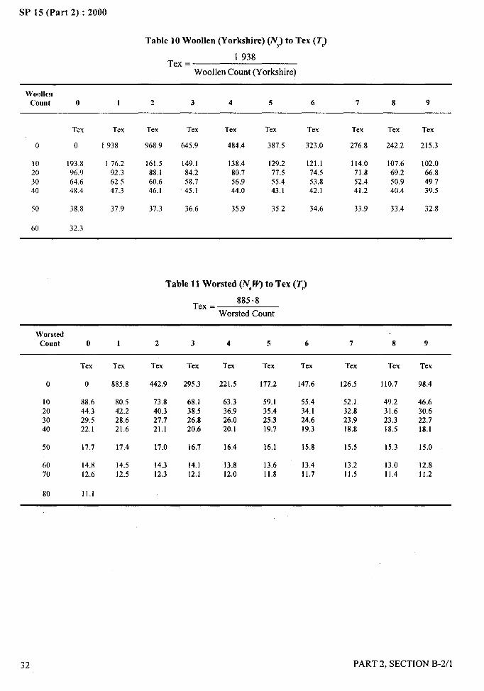
.,.,, ,&
“f
SP 15 (Part 2) :2000
Table 10 Woollen (Yorkshire) (NY)to Tex (7’,)
Tex =1938
Woollen Count (Yorkshire)
WoollenCount o I 2 3 4 5 6 7 8 9
Tex Tex Tex Tex Tex Tex Tex Tex Tex Tex
o 0 I 938 968.9 645.9 484.4 387.5 323.0 276.8 242.2 215.3
10 193.8 176.2 161.5 149,1 138.4 129.2 121.1 114.0 107.6 102.020 96.9 92.3 88.1 84,2 80.7 77.5 74.5 71.8 69.2 66.830 64.6 62.5 60.6 58.7 56.9 55.4 53.8 52.4 50.9 49.740 48.4 47.3 46.1 45.1 44.0 43.1 42.1 41.2 40.4 39.5
50 38.8 37.9 37.3 36.6 35.9 35.2 34,6 33.9 33.4 32.8
60 32.3
Table 11 Worsted (N~W’)to Tex (T,)
Tex =885.8
Worsted Count
WorstedCount o 1 2 3 4 5 6 7 8 9
0
10203040
50
6070
80
Tex Tex Tex Tex Tex Tex Tex Tex Tex Tex
o 885.8 442.9 295.3 221.5 177.2 147.6 126.5 I 10.7 98.4
88.6 80.5 73.8 68.1 63.3 59.1 55.4 52.1 49.2 46.644.3 42.2 40.3 38.5 36.9 35.4 34.1 32.8 31.6 30.629.5 28.6 27.7 2&8 26.0 25.3 24.6 23.9 23.3 22.722.1 21.6 21.1 20.6 20.1 19.7 19.3 18.8 18.5 18.1
17.7 17.4 17.0 16.7 16.4 16.1 15.8 15.5 15.3 15.0
14.8 14.5 14.3 14.1 13.8 13.6 13.4 13.2 13.0 12.812.6 12.5 12.3 12.1 12.0 11.8 11.7 11.5 11.4 11.2
11.1
32 PART 2, SECTION B-2/l
,,
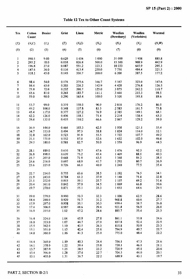
SP 15 (Part 2) :2000
Table 12 Tex to Other Count Systems
Tex
(z)
(1)
12345
678910
1112131415
1617181920
2122232425
2627282930
3132333435
3637383940
4142434445
CottonCount
(NCC)
(2)
590,5295.2196.8147.6118.1
98.484.473.865.659.0
53.749.2
45.442.239.4
36.934.732.831,129.5
28.126.825.724.623.6
22.721.921,120.419.7
19.018.417.917.416.9
16.416.0
15.515.114.8
14.414.113.713.413.1
Denier
(T,)
(3)
9.0018.027.036.045.0
54.063.072.081.090.0
99.0108.0117.0126.0135.0
144.0153.0162.0171.0180.0
189,0198.0207.0216.0225.0
234.0243.0252.0361.0270.0
279.0288,0297.0306.0315.0
324.0333.0342.0351.0360.0
369.0378.0387.0396.0405.0
Grist
(T)
(4)
0.029
0.0870.1160,145
0.1740.2030.2320.2610.290
0.3190.3480.3770.4060.435
0.4640.4940.5230.5520.581
0.6100.6390.6680.6970,726
0.7550.7840.8130.8420.871
0.9000.9290.9580.9871.02
1.041.071.101.131,16
1.191.221.251.281.31
Linen
(N.L)
(5)
1654826.8551.2413.4330.7
275.6236.2206.7183.7165.4
150.3137.8127.2118.1110.2
103.397.391.987.082.7
78.775.271.968.966.1
63.661.259.157.055.1
53.351.750.148.647.2
45.944,743,542.441.3
40.339.438.537.636.7
Metrie
(NJ
(6)
1000500.0333.3250,0200.0
166.7142.9125.0111.1100.0
90.983.376.971.466.6
62.558.855.552.650.0
47.645,443.541.740.0
38.537.025.7
34.533.3
32.331.230.329.428.6
27.827.026.325.625.0
24.423.823.222,722.2
Woollen(Dewsbury)
(N,)
(7)
31000155001033377506200
51674428387534443100
28182583238522142067
19381824172216321550
14761409134812921240
11921148110710691033
1000968.8939.4921.8885.7
861.1837.8815.8794.9775.0
756.1738.1720.9704.5688.9
Woollen(Yorkshire)
(N,)
(8)
1938968.9645.9484.4387.5
323.0276.8242.2215.3193.8
176.2161.5149.1138.4129.2
121.1114.0107.7102.096.9
92.388.184.280,777.5
74.571.869.266.864.6
62.560.658.756.955.4
53.852.450.949.748.4
47.346.145,144,043.1
Worsted
(N.W)
(9)
885.8442.9295.3221.5177,2
147.6126.51)0.798.588.6
80.573.868.163.359.0
55.452.149.246.644.3
42.240.338.536.935.4
34.132.831.630.629.5
28.627.726.826.025.3
24.623.923.322.722.2
21.621.120.620.119.7
..ii
i’\
PART 2, SECTION B-2/l 33
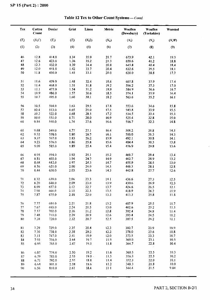
.-SP 15 (Part 2) :2000
Table 12 Tex to Other Count Systems — Conrd.
Tex
(K)
(1)
4647484950
5152535455
5657585960
6[62636465
6667686970
7172737475
7677787980
8182838485
8687888990
CottonCount
(N&)
(2)
12.812.612.312.011.8
11.611.411.110.910.7
10.510.410.210.0
9.84
9,689.529.37
9,239.09
8.958.818.688.568.44
8.328.208.097.987.87
7.777,677.577.487.38
7.297.20
7.117.036.95
6.876.796.716.646.56
Denier
(TJ
(3)
414.0423.0432.0441.0450.0
459.0468,0477.0486.0495.0
504.0513,0522.0531,0540.0
549,0558.0567.0576.0585.0
594.0603.0612.0621.0630.0
639.0648.0657.0666.0675.0
684.0693.0702.0711,0720.0
729.0738.0747,0756.0765.0
774.0783.0792.0801.0810.0
Grist
(T)
(4)
1.341.361.391.421.45
1.481.511.541.571.60
1.631.651.681.711.74
1.771.801.831.861.89
1.921.941.972.002.03
2,062.092.122.152.18
2.212.242.262.292.32
2.352.382.412.442.47
2.502.532.552.582.61
Lhsen
(NJ)
(5)
35.935.234.433.733.1
32.431.831.230.630.1
29,529.028.528.027.6
27.126.726.225.825.4
25.124.724.324.023.6
23.323.022.722.322,0
21.821.521,220,920.7
20.420.219.919.719.5
19.219.018.818.618.4
Metric
(NJ
(6)
21.721.320.820.420.0
19.619.218.918.518.2
17.817.517,216.9
16.6
16.416.115.915.6
15.4
15.214.914.714.514.3
14.113.913.713.513.3
13.213.012.812.612.5
12.312.212.0
11.911.8
11,611.511.411.211.1
Woollen(Dewsbury)
(N,)
(7)
673.9659.6645.8632.6620.0
607.8596.2584.9574.1563.6
553.6543.8534.5525.4516.7
508.2500.0492.1484.4476.9
469.7462.7455.9449.3442.8
436.6430.6424.6418.9413.3
407.9402.6392.4393.4387.5
382.7378.0373.5369.0364.7
360.5356.3352.3348.3344.4
Woollen(Yorkshire)
(N,)
(8)
42.141.240.439.538.8
37.937.336.635.935.2
34.633.933.432.832.3
31.831.330.830.329.8
29.428.928.528.127.7
27.326.926.526.225.8
25.525.224.824.524.2
23.923.623.323.122.8
22.522.322.021.821,5
Worsted
(N,W)
(9)
19.318.818.418.117.7
17.417.016.716.416.1
15,815.5
15.315.014.8
14.514.314.113.813.6
13.413.213.012.812,6
12.512.312.111,911.8
11.711.511.411.211.1
10.910.810.710.510,4
10.310.210.110.09.84
,\
34 PART 2, SECTION B-2/l
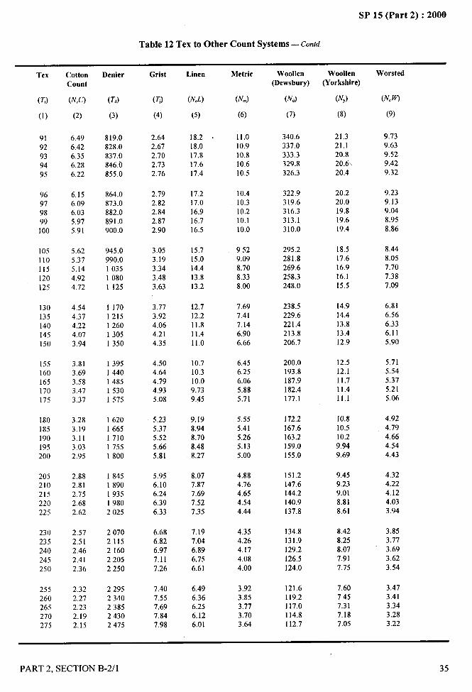
SP 15 (Part 2) :2000
Table 12 Tex to Other Count Systems — cord
.—
Tex
(TJ
(1)
9192939495
96979899100
105110115I20125
130135140145150
155160165170175
180185190195200
205210215220225
230235240245250
255260265270275
CottonCount
(NCC)
(2)
6.496.426.356.286.22
6.156.096.035.975.91
5.625.375.144.924.72
4,544.374,224.073.94
3.813,693.583.473.37
3.283.193.113.032.95
2.882.812.752.682.62
2.572.512.46
2.412.36
2.322.272.232.192.15
Denier
(T,)
(3)
819.0828.0837.0846.tl855.0
864.0873.0882.0891.0900.0
945.0990.0103510801125
11701215126013051350
13951440148515301575
16201665171017551800
18451890193519802025
20702115216022052250
22952340238524302475
Grist
(T)
(4)
2.642.672.702.732.76
2.792.822.842,872.90
3.053.193.343.483.63
3.773.924.064.214.35
4,504,644.794.935.08
5.235.375.525.66
5.81
5.956.106.246.396.33
6.686.826.977.117.26
7.407.557.697.847.98
Linen
(NCL)
(5)
18.218.017,817.617.4
17.217.016.916.716.5
15.715.014,413.813.2
12.712.211.811.411.0
10.710.310.09.739,45
9.198.948.708.488.27
8.077.877.697.527.35
7.197.046.896.756.61
6.496.366.256.126.01
Metric
(NJ
(6)
11.010.910.810.6
10.5
10.410.310.210,110.0
9.529.098.708.33
8.00
7.697.417.146.906.66
6,456.256.065.885.71
5.555,41
5.265.135.00
4.884.764.654.544.44
4.354.264.17
4.084.00
3.923.853.773.703.64
Woollen(Dewsbury)
(N,)
(7)
340.6337.0333.3329.8326.3
322.9319.6316.3313.1310.0
295.2281.8269.6258.3248.0
238.5229.6221.4213,8206.7
200.0193.8187.9182.4177.1
172.2167.6163.2159.0155.0
151.2147.6144.2140.9137.8
134.8131.9129.2126.5124.0
121.6119.2117.0114.8112.7
Woollen(Yorkshire)
(N,)
(8)
21.321.120.820.620.4
20.220.019.819,619.4
18.517.616.916.115.5
14.914.413.813.412.9
12.512.111.711.411.1
10.810.510.29.949.69
9.459.239.018.818.61
8.428.258.077.917.75
7.607.457.317.187.05
Worsted
(N.~
(9)
9.739.639.529.429.32
9.239.139.048.958.86
8.448.057.707.387.09
6.816.566.336,115.90
5.715.545.375.215.06
4.92, 4.79
4.664.544.43
4.324.224.124.033.94
3.853.773.693.623.54
3.473.413.343.283.22
--q-.
PART 2, SECTION B-2/l 35

SP 15 (Part 2) :2000
Table 12 Tex to Other Count Systems — Contd.
Tex
(TJ
(1)
280285290295300
305310315320325
330335340345350
355360365370375
380385390395400
405410415420425
430435440445450
455460465470475
480485490495500
CottonCount
(N.C)
(2)
2.112.072.042.001.97
1.941.901.87
1.841.82
1.791.761.741.711.69
I .661.641.621.601.57
1.551.531.511.491.48
1.461.441.421.411.39
1.371.36
1.341.331.31
1.301.281.271.26
1.24
1.231.221.201.191.18
Denier
(Td)
(3)
25202565261026552700
27452790283528802925
29703015306031053150
31953240328533303375
34203465351035553600
36453690373537803825
38703915396040054050
40954140418542304275
4320436544104,4554.500
Grist
(~)
(4)
8.138.278.428.568.71
8.859.009.149.299.43
9.589.729.8710.010.2
10.310.510.610.710.9
11.011.211.311.411.6
11,811.912.012.212.3
12.512.612.812.913.1
13.213.413.513.613.8
13.914.114.214.414.5
Linen
(N.L)
(5)
5.915.805.705.615.51
5.425,335.255.175.09
5.014,944.864.794,72
4.664.594.534.474.41
4.354.304,244.194.13
4.084.033.993.943.89
3.853.803.763.723.67
3.643.593.563.523.48
3.443.413.373.343.31
Metric
(N&)
(6)
3.573.003.453.393.33
3.283.233.173.123.08
3.032.992.942.902.86
2.822.782.742.702.67
2,632.602.562.532.50
2.472.442.412.382.35
2.322.302.272.252.22
2.202.172.152.132.11
2.082.062.042.022.00
Woollen(Dewsbury)
(N,)
(7)
110.7108.8106.9105.0103.3
101.6100.098.496.995.4
93.992.592.289.988.6
87.386.184.983.882.7
81.680.579.578.577.5
76.575,674.773.872.9
72.171.370.469.768.9
68.167.466.766.065.3
64.663.9
63.362.6
62.0
Woollen(Yorkshire)
(NJ
(8)
6.92
6.806.686.57
6.46
6.356.256.156.065.96
5.875.795.695.625.54
5.465.385.315.245.17
5.095.034.974.914.84
4.794.734.674.614.56
4.514.464.404.364,31
4.264.214,174.124.08
4.044.00
3.953.923.88
Worsted
(N.W)
(9)
3.163.113.063.002.95
2.902.862.812.772.73
2.682.642.602.572:53
2.502.462.432.392.36
2.332.302.272.242.22
2.192.162.132.112,08
2.062.042.011.991.97
1.951.931.901.881.86
1.841.831.811.791.77
36 PART 2, SECTION B-2/l
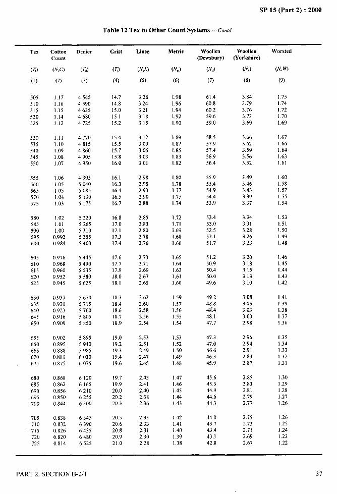
i
/
SP 15 (Part 2) :2000.-. ..—
Table 12 Tex to Other Count Systems — contd. —.
Tex
(z)
(1)
505510515520525
530535540545550
555560565570575
580585590595600
605610615620625
630635640645650
655660665670675
680685690695700
705710715720725
CottonCount
(N,C)
(2)
1.171.161.151.141.12
1.11
1.101.091.081.07
1.061.051.051.041.03
1.021.011.00
0.9920.984
0.9760.9680.9600.9520,945
0.9370.9300.9230.9160.909
0.9020.8950.8880.8810.875
0,8680.8620.8560.8500.844
0.8380.8320.8260.8200.814
Denier
(T,)
(3)
454545904635
46804725
47704815486049054950
49955040508551305175
52205265531053555400
54455490553555805625
56705715576058055850
58955940598560306075
6120
6165621062556300
63456390643564806525
Grist
(T)
(4)
14.7
14.815.0
15.115.2
15.415.515.715.816,0
16.116.316.416.516.7
16,817.017.117.317.4
17,617.717.918.018.1
18.318.418.618.718.9
19.019,219.319.419.6
19.719.920.020.220.3
20.520.620.820.921.0
Linen
(NJ)
(5)
3.28
3.243.213.183.15
3.123.093.063.033.01
2.982.952.932.902.88
2.852.832,802.782.76
2.732.712.692.672.65
2.622.602.582.562.54
2.532.512.492.472.45
2.432.412.402.382.36
2.352.332.312.302.28
Metric
(NJ
(6)
1.981,96
1.941.921.90
1.891.871.851,831.82
1.801.781,771.751.74
1,721.711.691.681.66
1.651.641,631.611.60
1.591.571.561,551,54
1.531.521.501.491.48
1.471.46I .451.441.43
1.421.411.401.391.38
Woollen(Dewsbury)
(N,)
(7)
61.460.8
60.259.659.0
58.557.957.456.956.4
55.955.454.954.453.9
53.453.052.552.151.7
51.250.950.450.049.6
49.248.848.448.147.7
47.347.046.646.345.9
45.645.344.944.644.3
44.043.743.443.142.8
Woollen(Yorkshire)
(N,)
(8)
3.84
3.793.763.733.69
3.663.623.593.563.52
3.493.463.433.393.37
3.343.313.283.263.23
3.203.183.153.133.10
3.083.053.033.002,98
2.962.942.912.892.87
2.852.832.812.792.77
2.752.732.712.692.67
Worsted
(NCW)
(9)
1.751.741.721,701.69
1.671.661.641.631.61
1.601.581.571.55[,54
1.531,51!.501.491.48
1.461.451.441.431.42
1.411.391.381.371.36
1.351.341.331.321.31
1.301.291.281.271.26 I
1.261,251.241.231.22
PART 2, SECTION B-2/l 37
I
I
1’1l!
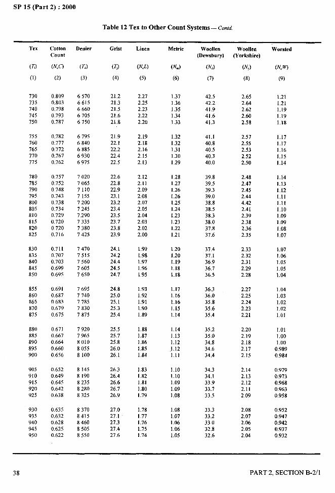
SP 15 (Part 2) :2000
Table 12 Tex to Other Count Systems — Contd.
Tex
(T!)
(1)
730
735740745750
755760765770775
780785790795800805810815820825
830835840845850
855860865870875
880885890895900
905910915920925
930935940945950
CottonCount
(N@)
(2)
0,8090.8030.7980,7930.787
0.7820.7770.7720.7670.762
0.7570.7520.7480.7430,7380.7340,7290.7200.7200.716
0.7110.7070.7030.6990.695
0,6910.6870.6830.6790.675
0.6710.6670.6640.6600.656
0.6520.6490.6450.6420.638
0.6350.6320.6280.6250.622
Denier
(T,)
(3)
6570
6615666067056750
67956840
688569306975
7020706571107155720072457.290733573807425
747075157560
76057650
76957740778578307875
79207965801080558100
81458190823582808325
83708415846085058550
Grist
(T)
(4)
21.221.321.5
21.621.8
21.922.122.222.422.5
22.622.822.923.123.223.423.523.723.823.9
24.124.224.424.524.7
24.825.025.125.325.4
25.525.725.826.026.1
26.326.426.626.726.9
27.027.127.327.427.6
Linen
(N.L)
(5)
2.272.252.232.222.20
2.192.182.162,152.13
2.122.112.092.082.072.052.042.032.022.00
1.991.981.971.96I.95
1.931.921.911.901.89
1.881.871.861.851.84
1.831.821.811.801.79
1.781.771.761.751.74
Metric
(Nm)
(6)
1.371.361.351.341.33
1.321.321.31
1.301.29
1.281.271.261.261.251.241.231.231.221.21
1.201.201.191.181.18
1.171.161.161,151.14
1.141.131.12
.1.121.11
1.101.101.091,091.08
1.081.071.061.061.05
Woollen(Dews bury)
(N,)
(7)
42.542.241.941.641.3
41.140.840.5
40.340.0
39.839.539.339.038.838.538.338.037.837.6
37.437.136.936.736.5
36.336.035.835.635.4
35.235.034.834.634.4
34.334.133.933.733.5
33.333.233.032.832.6
Woollen
(Yorkshire)
(N,)
(8)
2.652.642.622.602.58
2.572.552.532.522.50
2.482.47
2.452.444.422.412.392.382.362.35
2.332.322.312.292.28
2.272.252.242.232.21
2.202.192.182.172.15
2.142.132.122.112.09
2.082.072.062.052.04
Worsted
(NCW)
(9)
1.211.211.191.191.18
1.171.171.161.151.14
1.141.131.121.111.111.101.091.091.081.07
1.071.061.051.051.04
1.041.031.021.021.01
.. —.7
1.011.001.00
0.9890.984
0.9790.9730.9680.9630.958
0.9520.9470.942 I0.9370,932
38 PART 2, SECTION B-2/l .-
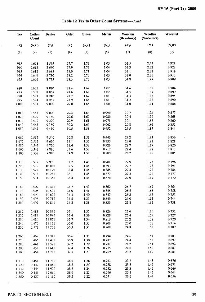
SP 15 (Part 2) :2000
Table 12 Tex to Other Count Systems — COntd
Tex
(TJ
(1)
955960965970975
980985990995
1000
10101020103010401050
10601070108010901100
11101120I 13011401 150
1 1601 17011801190I 200
12101220
123012401250
1260I 270128012901300
13101320133013401350
CottonCount
(N,C)
(2)
0.618
0.6150.6120.6090.606
0.6030.5990.5970.5940,591
0.5850.5790.5730,5680.562
0.5570.5520.5470.5420.537
0.5320.5270.5220.5180.514
0.5090.5050.5000.4960.492
0.4880.4840.4800.4760.472
0.4690.4650.4610.4580.454
0.4510.4470.4440.4410.437
Denier
(T,)
(3)
85958640868587308775
88208865891089559000
90909180927093609450
95409630972098109900
999010080101701026010350
1044010530106201071010800
10890109801107011 16011250
11340114301152011610I I 700
1179011880I I 9701206012150
Grist
(T)
(4)
27.727.928.028.228.3
28.428.628.728.929.0
29.329.629.930.230.5
30.831.131.431.631.9
32.232.532.833.133.4
33.734.034.334.534.8
35.135.435,736.036.3
36.636.937,237.437,7
38.038.338.638,939.2
Linen
(NJ)
(5)
1.731.721.711.701.70
1.691.681.671.661.65
1.641.621.611.601.58
1.561.551.531.521.50
1.491.481.461.451.44
1.431.411.401.391.38
1.371.361.341.331.32
1.311.301.291.281.27
1.261.251.241.231.22
Metrie
(NJ
(6)
1.051.041.041.031.03
1.021.021.011.011.00
0.9900.9800.9710.9620,952
0.9430,9350.9260.9170.909
0.9010.8930.8850.8770.870
0.8620.8550.8470.8400.833
0.8260.8200.8130.8060.800
0.7940.7870.7810.7750.769
0.7630.7580.7520.7460.741
Woollen(Dewsbury)
(N,)
(7)
32.532.332.132.031.8
31.631.531.331.231.0
30.730.430.129.829.5
29.229.028.728.428.2
27.927.727.427.227.0
26.726.526.326.025.8
25.625.425.225.024.8
24.624.424.224.023.8
23.723.523,323.123.0
Woolien(Yorkshire)
(NJ
(8)
2.032.022.01
2.00I .99
1.981.971.961.951.94
1.921.901.881.861.85
1.831.811.791.781.76
1.751.731.721.701.69
1.671.661.641.631.62
1.601.591.581.561.55
1.541.531.511.501.49
1.48I .471.461.451.44
Worsted
(N.W)
(9)
0.9280.9230.9180.9130.909
0.9040.8990.8950.8900.886
0.8770.8680.8600.8520.844
0.8360.8280.8200.8130.805
0.7980.7910.7840.7770.770
0.7640.7580.7510.7440.738
0.7320.727
0.7200.7140.709
0.7030.6970.6920.6870.681
0.6760.6710.6660.6610.656
PART 2, SECTION B-2il 39
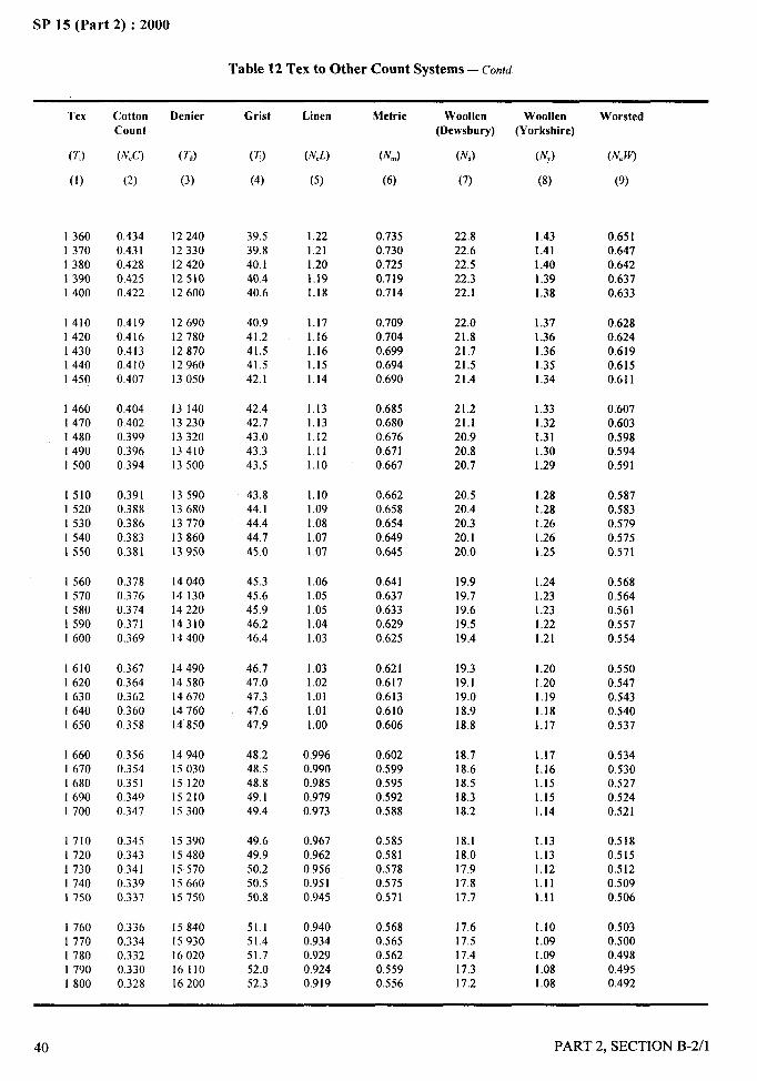
,“/
{.. .. .—
SP 15 (Part 2) :2000
Table 12 Tex to Other Count Systems — c’onrd
Tex
(7J
(1)
136013701380I 3901400
14101420I 4301440I 450
146014701480I 490I 500
1510I 520I 5301540i 550
15601570[ 580
15901600
16101620163016401650
16601670168016901700
17101720173017401750
1760I 770178017901800
CottonCount
(NCC)
(2)
0,4340.4310.4280.4250.422
0.4190.4160.4130.4100.407
0.4040.4020.3990.3960.394
0.3910.3880.3860.3830.381
0,3780.3760.3740.3710.369
0.3670.3640.3620.3600.358
0.3560.3540.3510.3490.347
0.3450.3430.3410.3390.337
0.3360.3340.3320.3300.328
Denier
(T,,)
(3)
1224012330124201251012600
1269012780128701296013050
1314013230133201341013500
135901368013770
1386013950
1404014130142201431014400
1449014580146701476014850
1494015030151201521015300
153901548015570
1566015750
1584015930160201611016200
Grist
(H
(4)
39.539,840,140.440.6
40.941,241.541.542,1
42.442.743.043,343.5
43.844.144.444,7
45.0
45.345.645.946.246.4
46.747.047.347.647.9
48.248.548.849.149.4
49.649.950.250.550.8
51.151,451.752.052.3
Linen
(N.L)
(5)
1,221.211.201,191.18
1.171.161.161.151.14
1.131,131.121.111.10
1,101.091.081.071.07
1,061.05I .051,041.03
1.031.021.011.011.00
0.9960.9900.9850.9790.973
0.9670.9620.9560.9510.945
0.9400.9340.9290.9240.919
Metric
(Nn,)
(6)
0.7350.7300.725
0.7190.714
0.7090,7040.6990.6940.690
0.6850.6800.6760.6710.667
0.6620.6580.6540.6490.645
0.6410.6370.6330.6290.625
0.6210.6170.6130.6100.606
0.6020.5990.5950.5920.588
0.5850.5810.5780.5750.571
0.5680.5650.5620.5590.556
Woollen
(Dewsbury)
(N,)
(7)
22.822.622.522.322.1
22.021.821.721.521.4
21.221.120.920.820.7
20.520.420.320.120.0
19.919.719.619.5
19.4
19.319.119.018.918.8
18.718,618.518.318.2
18.118.017.9
17.817.7
17.617.517.417.317.2
Woollen(Yorkshire)
(N,)
(8)
1.431.411.401.391.38
1.371.361.361,351.34
1.331.32
1.311.301.29
1,28
1.281.26
1.261,25
1.241.231.231.221.21
1.20I .201.191.181.17
1.171.161.151.151.14
1.131.131.121.111.11
1.101.091.091.081.08
Worsted
(NCW)
(9)
0.6510.6470.6420.6370.633
0.6280.6240.6190.6150.611
0.6070.6030.5980.5940.591
0.5870.5830.5790.5750.571
0.5680.5640.5610.5570.554
0.5500.547
0.5430.5400.537
0.5340.5300.5270.5240.521
0.5180.5150.5120.5090.506
0.5030.5000.4980.4950.492
40 PART 2, SECTION B-2/l
I I
1’!
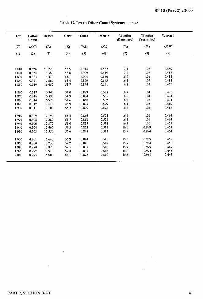
A-
. ...-
SP 15 (Part 2) :2000
Table 12 Tex to Other Count Systems — cond—,~
*j
Tex
(TJ
(1)
18101820183018401850
18601870188018901900
19101920193019401950
19601970198019902000
CottonCount
(N,C)
(2)
0.3260.3240.3230.3210.319
0.3170.3160.3140.3120.311
0.3090.3080.3060.3040.303
0.3010.3000.2980.2970.295
Denier
(Td)
(3)
1629016380164701656016650
1674016830169201701017100
1719017280173701746017550
1764017730178201791018000
Grist
(~)
(4)
52.552.853.153,453.7
54.054.354,645.9
55.2
55.455.756.056.3
56.6
56.9
57.257,557.858.1
Linen
(NCL)
(5)
0.9140.9090.9040.8990.894
0.8890.8840.8800.8750.870
0.8660.8610.8570.8530.848
0.8440.8400.8350.8310.827
Metric
(N~)
(6)
0.5520.5490.5460.5430.541
0,5380.5350.5320.5290.526
0.5240.5210.5180.5150.513
0.5100.5080.5050.5030.500
Woollen(Dewsbury)
(N,)
(7)
17.117.016.916.816.8
16.716.616.516.416.3
16.216.116,116.015.9
15.815.715.715.615.5
Woollen(Yorkshire)
(IW
(8)
1.071.061.061.051.05
1.041.041.031.031.02
1.011.011.00
0.9990.994
0.9890.9840.9790.9740.969
Worsted
(N.W)
(9)
0.4890.4870.4840.4810.479
0.4760.4740.4710.4690.466
0.4640.4610.4590.457
0.454
0,4520.4500.4470.4450.443
PART 2, SECTION B-2/l 41

SP 15 (Part 2) :2000
..—
DETERMINATION OF LINEAR DENSITY OF..-
YARNS SPUN ON COTTON SYSTEM
(source: IS 1315: 1977)r $,;
{-’!. ....- ,.$
‘1
1 SCOPE
It prescribes the procedure for determination of lineardensity of yarn spun on cotton system in cotton countand tex. It is applicable to single, plied and cabled yarns.
2 SAMPLING
The samples shall be drawn in accordance with theprocedure laid down in IS 3920:1985 ‘Methods forsampling of cotton yam for determination of physicalcharacteristics (see Section A-1 /1)’.
3 ATMOSPHERIC CONDITIONS FORCONDITIONING AND TESTING
3.1 The sample shall be conditioned to moistureequilibrium in standard atmosphere of 65 * 2 percentrelative humidity and 27 * 2°C temperature (see also
IS 6359:1971 ‘Method for conditioning of textiles’).
3.2 The test shall be carried out in the standardatmosphere (see 3.1).
4 APPARATUS
For the purpose of this test any of the following apparatus
may be used depending upon the availability.
.4.1 Any Special Balance
To indicate the linear density directly when a skein ofknown length of yarn is placed or hung on one side ofthe balance.
4.2 Pan Balance
Capable of measuring to an accuracy of 1 mg..,
4.3 Wrap Reel ‘
Having 1.372m (1.5 yd) or 1 m girth (see Annex A)and capable of reeling known lengths of yam.
4.4 Yarn Tensioning Device
An adjustable tensioning device capable of giving areeling tension that will result in skeins of the specifiedlength when measured on a skein gauge. The adjustment
42
in reeling tension maybe made, for example, by makingmore than one wrap around thread guides or by passingthe yam around tensioning bars. The reeling tension shallbe the same at all reeling positions and maybe checkedas follows:
The yam is wound fi-om the same package at differentreeling positions. The length of the skeins when measured
on a skein gauge shall not differ by more than 0.1 percent.
4.5 Skein Gauge
A gauge for checking the length of the skein under aload of 0.5 gf/tex (5 mN/tex) and expressing the lengthas a plus or minus deviation from the nominal length.The sensitivity of the skein gauge shall be sufficient topermit rejection of skeins falling outside +0.25 percenttolerances. The skein-gauge length may be adjustableor non-adjustable. A non-adjustable skein gauge maybe used when its nominal length differs by not more than0.4 percent from the measured perimeter of the reel.
NOTE— For detailsof skeingauge(seeAnnexB).
5 PROCEDURE-.
~’”
5.1 Cotton Count System j%, -.
5.1.1 Special Yarn Count of Balance
Prepare a skein of 109.73m ( 120yd) on the wrap reel(see Annex A) or take the specified length of yarn, andplace or hang it on the balance and read off the linear
density of yam from the scale provided.
5.1.2 Pan Balance
Reel out skeins of 109.73 m (120 yd) on the wrap reel(see Annex A) and then determine their mass in gramsindividually on the balance correct to 1 mg. Calculatethe linear density of yam as given in 6.1.
5.2 Tex System
5.2.1 Special Yarn Count Balance
Prepare a skein of 100 m on the wrap reel (see Annex I
A) or take the specified length of yam, and place or
PART 2, SECTION B-2/2

.- ..—
SP 15 (Part 2) :2000
hang it on the balance and read off the linear density ofyam from the scale provided.
5.2.2 Pan Balance
Reel out skeins of 100 m on the wrap reel (see Annex A)and determine their mass in grams, individually on thebalance correct to 1 mg. Calculate the linear density ofyam as given in 6.2.
5.3 Test At Least 30 Test Specimens
6 CALCULATIONS
6.1 Cotton Count System
Calculate linear density of cotton yam in the cotton countsystem up to one decimal place by the following formula:
453.6 64.8~c=—. —
7xrn m
whereNo= cotton yam count; and
m = mass of skein of 109.73 m (or 120 yd), in grams(see 5.1.2).
6.2 Tex System
Calculate the linear density of yam in tex system up toone decimal place by the following formula:
l=&xlOOO=l Om
—where -
t = count of yam in tex; andm = mass of skein of 100 m, in grams (see 5.2.2).
1,7..,—--
6.3 CaIculate the average of all the values up to onedecimal place and report it as the average linear densityof yarn.
6.4 Calculate the coefficient of variation (CV) of all thelinear density observations made.
6.5 For conversion of cotton countfollowing formula shall be used:
to tex system the
~ex= 590.5
iv.
6.5.1 For interconversion of values from one systemto the other, reference to IS 3689:1966 ‘Conversionfactors and conversion tables for yarn counts’ (seeSection B-2/l ) maybe made.
7 REPORT
The report shall include the following information:
a)
b)
c)
d)
Type of yam,
Average linear density in cotton count system .-and tex system, 1
CV of linear density, and
Number of test specimens tested.‘\.,,(’.
ANNEX A
(Clauses 4.3,5 .1.1,5.1.2,5.2.1 and5.2.2)
PREPARATION OF SKEINS
A-1 APPARATUS
A-1.l To reel off the skeins, a wrap reel having a girthof 1.372m ( 1.5 yd) or 1 m shall be used. The wrap reelshall be fitted with thread guides fixed on a horizontalbar which has a traverse of about 25 mm. The wrapreel shall also be provided with a counting device toindicate the length of yarn reeled out and bell to ring
just before the last revolution or a reel that automaticallystops after the required number of revolutions.
A-2 PROCEDURE
A12.1 Mount a test package on the wrap reel. Pass theend through the thread guides taking care that the yamshall be kept under sufficient tension to avoid kinks, curlsand slack in the yam on the one hand and stretch on theother (see Note) and lead it to the reel. i’
NOTE— If necessary, yam maybe wound full one turn aroundthe thread guide. I
A-2.2 Start the wrap reel. Running it at uniform speed, Ireel out a skein of required length. Cut and tie the trailingend of the skein to its leading end.
PART 2, SECTION B-2/2 43
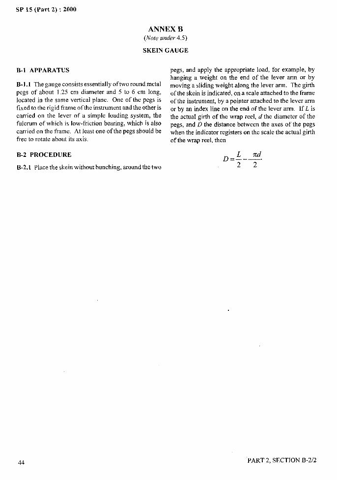
. !?+
SP 15 (Part 2) :2000
ANNEX B(Note under 4.5)
SKEIN GAUGE
B-1 APPARATUS
B-1. 1 The gauge consists essentially of two round metal
pegs of about 1.25 cm diameter and 5 to 6 cm long,located in the same vertical plane. One of the pegs isfixed to the rigid frame of the instrument and the other iscarried on the lever of a simple loading system, thefulcrum of which is low-friction bearing, which is alsocarried on the frame. At least one of the pegs should befree to rotate about its axis.
B-2 PROCEDURE
B-2.1 Place the skein without bunching, around the two
44
pegs, and apply the appropriate load, for example, byhanging a weight on the end of the lever arm or bymoving a sliding weight along the lever arm. The girthof the skein is indicated, on a scale attached to the frameof the instrument, by a pointer attached to the lever armor by an index line on the end of the lever arm. If L isthe actual girth of the wrap reel, d the diameter of thepegs, and D the distance between the axes of the pegswhen the indicator registers on the scale the actual girthof the wrap reel, then
xdD=;–—
2
PART 2, SECTION B-2/2
—..
.-
!
‘;\+,
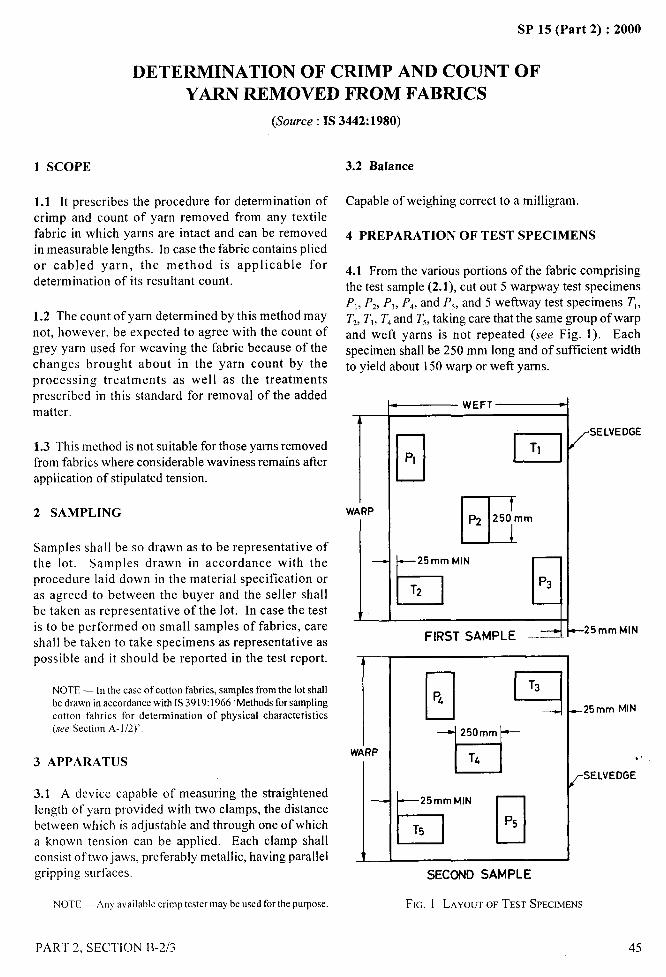
-—SP 15 (Part 2) :2000
DETERMINATION OF CRIMP AND COUNT OF
YARN REMOVED FROM FABRICS
(Source: IS 3442:1980) --! ,,,
1 SCOPE
1.1 It prescribes the procedure for determination ofcrimp and count of yarn removed from any textilefabric in which yarns are intact and can be removedin measurable lengths. In case the fabric contains pliedor cabled yarn, the method is applicable for
determination of its resultant count.
1.2 The count of yarn determined by this method maynot, however, be expected to agree with the count ofgrey yarn used for weaving the fabric because of thechanges brought about in the yarn count by theprocessing treatments as well as the treatmentsprescribed in this standard for removal of the addedmatter.
1.3 This method is not suitable for those yarns removedfrom fabrics where considerable waviness remains afterapplication of stipulated tension.
2 SAMPLING
Samples shall be so drawn as to be representative ofthe lot. Samples drawn in accordance with theprocedure laid down in the material specification oras agreed to between the buyer and the seller shallbe taken as representative of the lot. In case the testis to be performed on small samples of fabrics, careshall be taken to take specimens as representative aspossible and it should be reported in the test report.
NOTE — In the case of cott(m fabrics, samples from the lot shallbe drawn in accordance with IS 3919:1966 ‘Methodsfor samplingcotton fabrics for determination of physical characteristics(we Section A-1/2)’.
3 APPARATUS
3.1 A device capable of measuring the straightenedlength of yarn provided with two clamps, the distancebetween which is adjustable and through one of whicha known tension can be applied. Each clamp shallconsist of two jaws, preferably metallic, having parallelgripping surfaces.
NOTE — Any availahlc crimp tester maybe used for the purpose.
PART 2. SECTION B-2/3
3.2 Balance
Capable of weighing correct to a milligram.
4 PREPARATION OF TEST SPECIMENS
4.1 From the various portions of the fabric comprising
the test sample (2.1), cut out 5 warpway test specimensP,, Pz, P,, Pd, and P,, and 5 we ftway test specimens T],
T,, T,, T, and T,, taking care that the same group of warp
and weft yarns is not repeated (see Fig. 1). Eachspecimen shall be 250 mm long and of sufficient widthto yield about 150 warp or weft yams.
rWARP
L
—
rWARP
1—
— WEFTC
DPI nTI
E
pz 250mm
~~m;.ltd ~
FIRST SAMPLE --–-
4250mm&
B“’”El
/SELVEDGE
‘\\
–25mm MlN
–25mm MIN
. .
rSELVEDGE
SECOND SAMPLE
IFIG. 1 LAYOUTOF TEST SPECIMENS
45
/
II,$ I
. &
SP 15 (Part 2) :2000
5 ATMOSPHERIC CONDITION FOR thus obtained, calculate the average straightened length
CONDITIONING AND TESTING between the marks (1, ) of 10 warp yarns.
5.1. The test specimens shall be conditioned in standard 6.1.3 Calculate the crimp percent in the yarn by the
atmospheric conditions of 65 + 2°C percent relative following formula:
humidity and 27+ 2°C temperature to moistureequilibrium from dry side (see IS 6359:1971 ‘Method 1,-1
for conditioning of textiles’ (Section B-l/l).=—x 100
1
5.2 The tests shall be carried out in standard atmospheric where
conditions. 11= average length in millimetres of the yams when
straightened, and
6 PROCEDURE I = length in millimetres of the yams while in cloth.
6.1 Warp Yarn
6.1.1 For determining the approximate universal countof the warp yam in tex, which is necessary for calculatingthe tension to be applied during the test, take one of the
warpway test specimens. Draw two parallel marks 200mm apart at right angles to the direction of warp. Remove
10 warp yams and cut them along the marks with a sharp’razor blade and template. Determine the mass of all the
NOTE — The crimp percent maybe determined by using crimptester, following the procedure as prescribed in the instrumentmanual.
6.1.4 Cut the test specimen along the marks with a sharprazor blade and template. Remove sufficient number ofwarp yams (see Note) out of the specimen so that thetotal length of the yams removed is about 10 m, andplace them in a suitable container.
yarns in milligrams and calculate the approximateuniversal count of the yarn in tex by the following
NOTE — It may be necessary to trim off the protruding weft
formula:yarns frequently to avoid flaying of the warp yams.
6.1.5 Calculate the total length (L) of the yams collectedt=; in the container in millimetres taking the average length
between the marks (/,) determined as in 6.1.2, as thewhere length of each yam.
t = approximate universal count in tex of the warpyarn, and
m = mass in milligrams of 10 warp yams.
6.1.2 Take the test specimen P, and draw two parallelmarks 200 mm (/) apart at right angles to the directionof warp. Ravel a warp yam out of the test specimen P{to a length of about 50 mm. Hold the yarn as close tothe end as possible and fasten its loose end in the tensionclamp so that one of the marks on the yam coincideswith the inner edge of the tension clamp. Pull the yamout of the test specimen sideways, taking care not tostretch the yarn or release the other end of the yarn toavoid removal of any twist. Hold the yam as close tothe end as possible to avoid any untwisting. Draw theyarn through the other clamp and fix the yam such thatthe second mark on the yarn coincides with the inneredge of the clamp. Measure the length of the yarnbetween the two marks in millimetres under a tension of0.5 g/tex + 10 percent ( it should be noted that the tex ofyarn determined as in 6.1.1 for this purpose is onlyapproximate). In a similar manner, determine the lengthbetween the marks of 9 other warp yarns. From the data
6.1.6 Make the yams into bundles or loops and removethe finishing material as given in Annex A. Determinethe mass (M) of the yarns in milligram afler condkioning(see 5.1).
6.1.7 From the data thus onbtained, determine theuniversal count of the yarn in tex by the followingformula:
Universal count, in tex = z X 1 000L
where
M = total mass in milligrams of the yams (6.1.6),and
L = total length in millimetres of the yarns (6.1,5).
6.1.8 Determine the crimp and count of the warp yamin the remaining four test specimens, Pz, PJ, Pd, and Psin a similar manner. Find the average of the 5 values ineach case, round off these values to one decimal placeand report the values thus obtained as the crimp percentand count of the warp yam.
.. –.—.
I
46 PART 2, SECTION B-2/3
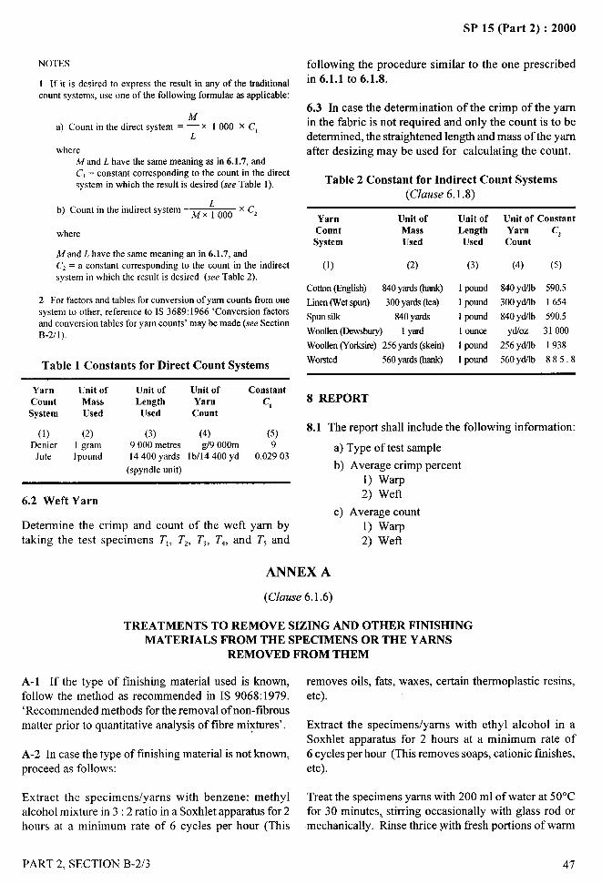
NOTES
1 If it is desired to express the result in any of the traditionalcount systems, use one of the following formulae as applicable:
Ma) Count in the direct system = — x 1000 x Cl
Lwhere
M and L have the same meaning as in 6.1.7, andC, = constant corresponding to the count in the directsystem in which the result is desired (see Table 1).
b) Count in the indirect system= ~ ~ ~ 000 x C,
where
Mand L have the same meaning an in 6.1.7, andC, = a constant corresponding to the count in the indirectsystem in which the result is desired (see Table 2).
2 For factors and tables for conversion of yarn counts from onesystem to other, reference to IS 3689:1966 ‘Conversion factorsand conversion tables for yarn counts’ may be made (see SectionB-2/1),
Table 1 Constants for Direct Count Systems
Yarn [Jnit of Unit of Unit of ConstantCount Mass Length Yarn c,System Used Used Count
(1) (2) (3) (4) (5)Denier 1 gram 9000 metres g/9 000m 9
Jute 1pound 14400 yards lb/14 400 yd 0.02903
(spyndle unit)
6.2 Weft Yarn
Determine the crimp and count of the weft yarn bytaking the test specimens T,, Tz, T,, Td, and T5 and
SP 15 (Part 2) :2000
following the procedure similar to the one prescribedin 6.1.1 to 6.1.8.
6.3 In case the determination of the crimp of the yarnin the fabric is not required and only the count is to bedetermined, the straightened length and mass of the yarnafter desizing may be used for calculating the count.
Table 2 Constant for Indirect Count Systems(Clause 6.1 .8)
Yarn Unit ofCount Mass
System lJsed
(1) (2)
Cotton(English) 840yards(hank)
Linen(Wetspun) 300yards(lea)
Spunsilk 840YxdsWoollen@cwsbury) 1yard
Woollen(Yorksire)256yards(skein)Worsted 560y~ds (@ink)
[Jnit ofLengthUsed
(3)
1pound
1pnsnd
1pound
1ounce
1parnd
1pound
Unit of ConstantYarn C,Count
(4) (5)
840ydilb 590.5300y~b 1654840yMb 590.5
yd!oz 31000256ydllb 1938
560yd/lb 885.8
8 REPORT
8.1 The report shall include the following information:
a) Type of test sample
b) Average crimp percent1) Warp2) Weft
c) Average count1) warp2) Wefl
ANNEX A
(Clause 6. 1.6)
TREATMENTS TO REMOVE SIZING AND OTHER FINISHINGMATERIALS FROM THE SPECIMENS OR THE YARNS
REMOVED FROM THEM
A-1 If the type of finishing material used is known, removes oils, fats, waxes, certain thermoplastic resins,
follow the method as recommended in IS 9068:1979. etc).
‘Recommended methods for the removal of non-fibrousmatter prior to quantitative analysis of fibre mixtures’. Extract the specimens/yarns with ethyl alcohol in a
Soxhlet apparatus for 2 hours at a minimum rate of
A-2 In case the type of finishing material is not known, 6 cycles per hour (This removes soaps, cationic finishes,
proceed as follows: etc).
Extract the specimensfyarns with benzene: methyl Treat the specimens yarns with 200 ml of water at 50°C
alcohol mixture in 3:2 ratio in a Soxhlet apparatus for 2 for 30 minutes,, stirring occasionally with glass rod or
hours at a minimum rate of 6 cycles per hour (This mechanically. Rinse thrice with fresh portions of warm
PART 2, SECTION B-2/3 47

SP 15 (Part 2) :2000
water (at 50”C) and dry (This removes water soluble every 3 minutes. Rinse throughly with water at 80°C
materials). containing a few drops of ammonia and then finally withplain water. Remove excess water from the sample by
Immerse the specimens/yarns in 200 ml of 0.1 N squeezing or suction centrifuge and allow to dry (This
hydrochloric acid at 80°C for 25 minutes, stirring gently removes starches/aminoaldehyde compound resins).
48 PART 2, SECTION B-2/3
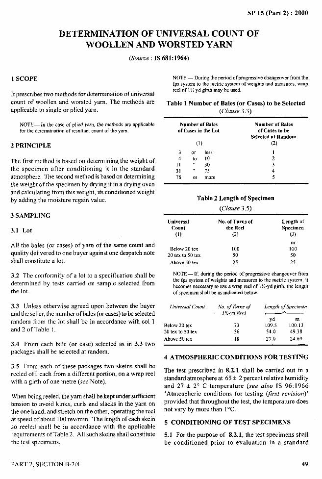
SP 15 (Part 2) :2000
DETERMINATION OF UNIVERSAL COUNT OF
WOOLLEN AND WORSTED YARN
(Source : IS 681 :1964)
1 SCOPE
It prescribes two methods for determination of universal
count of woollen and worsted yarn. The methods areapplicable to single or plied yarn.
NOTE— In the case of plied yam, the methods are applicablefor the determination of resultant count of the yarn.
2 PRINCIPLE
The first method is based on determining the weight ofthe specimen after conditioning it in the standardatmosphere. The second method is based on determiningthe weight of the specimen by drying it in a drying ovenand calculating from this weight, its conditioned weight
by adding the moisture regain value.
3 SAMPLING
3.1 Lot
All the bales (or cases) of yarn of the same count andquality delivered to one buyer against one despatch note
shall constitute a lot.
3.2 The conformity of a lot to a specification shall bedetermined by tests carried on sample selected fromthe lot.
3.3 Unless otherwise agreed upon between the buyerand the seller, the number of bales (or cases) to be selectedrandom from the lot shall be in accordance with CO11and 2 of Table 1.
3.4 From each bale (or case) selected as in 3.3 twopackages shall be selected at random.
3.5 From each of these packages two skeins shall bereeled off, each from a different portion, on a wrap reelwith a girth of one metre (see Note).
When being reeled, the yarn shall be kept under sufilcienttension to avoid kinks, curls and slacks in the yam onthe one hand, and stretch on the other, operating the reelat speed of about 100 revlmin.” The length of each skeinso reeled shall be in accordance with the applicablerequirements of Table 2. All such skeins shall constitutethe test specimens.
PART 2, SECTION B-2/4
NOTE — During the period of progressive changeover from thefps system to the metric system of weights and measures, wrapreel of 11%yd girth may be used.
Table 1 Number of Bales (or Cases) to be Selected(Clause 3.3)
Number of Balesof Cases in the Lot
(I)
3 or less4 to 10
11 “ 3031 “ 7576 or more
Number of Balesof Cases to be
Selected at Random(2)
12345
Table 2 Length of Specimen
(Clause 3.5)
Universal No. of Turns of Length ofCount the Reel Specimen
(1) (2) (3)
mBelow 20 tex 100 I00
20 tex to 50 tex 50 50
Above 50 tex 25 25
NOTE — If, during the period of progressive changeover fromthe fps system of weights and measures to the metric system, itbecomes necessary to use a wrap reel of 1%-yd girth, the lengthof specimen shall be as indicated below:
UniversalCount No. of Turnsof Length of Specimen1K-ydReel ( A >
ydBelow 20 tex 73 109,5 100:1320 tex to 50 tex 36 54.0 49.38
Above 50 tex 18 27.0 24.69
4 ATMOSPHERIC CONDITIONS FOR TESTING
The test prescribed in 8.2.1 shall be carried out in astandard atmosphere at 65* 2 percent relative humidityand 27 + 2° C temperature (see also IS 96:1966‘Atmospheric conditions for testing @st revision)’
provided that throughout the test, the temperature doesnot vary by more than 1“C.
5 CONDITIONING OF TEST SPECIMENS
5.1 For the purpose of 8.2.1, the test specimens shallbe conditioned prior to evaluation in a standard
49
1
,,
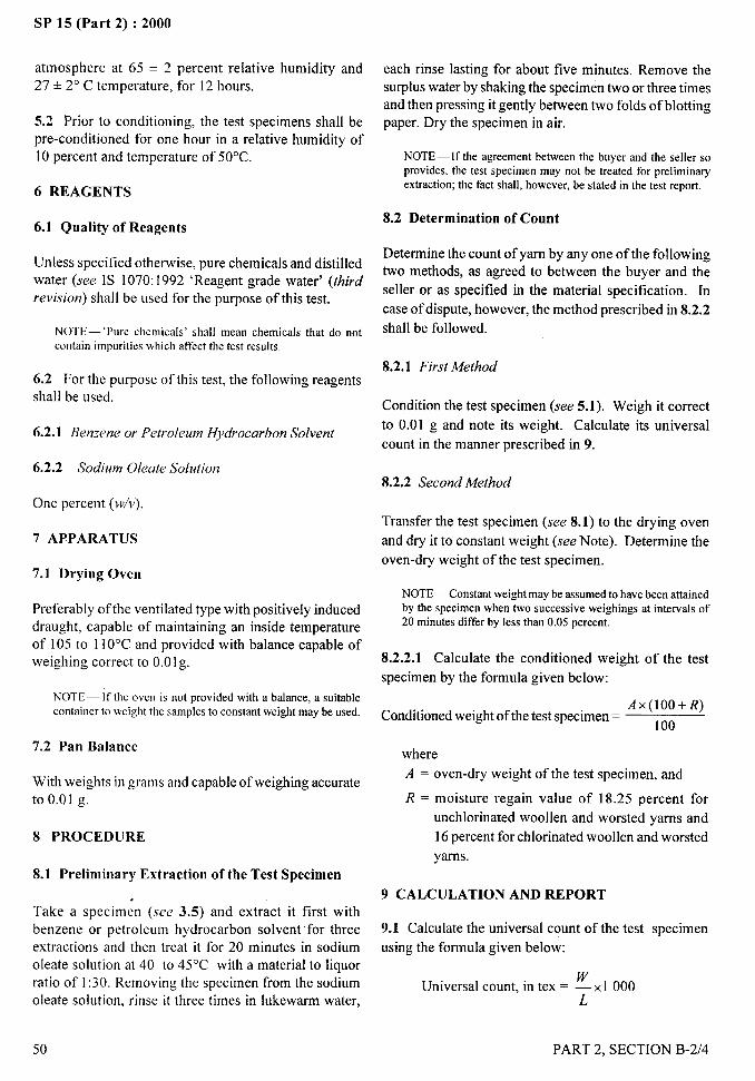
. .—SP 15 (Part 2) :2000
atmosphere at 65 + 2 percent relative humidity and27 * 2° C temperature, for 12 hours.
each rinse lasting for about five minutes. Remove thesurplus water by shaking the specimen two or three timesand then pressing it gently between two folds of blottingpaper. Dry the specimen in air.5.2 Prior to conditioning, the test specimens shall be
pre-conditioned for one hour in a relative humidity of10 percent and temperature of 50°C. NOTE— If the agreement between the buyer and the seller so
provides, the test specimen may not be treated for preliminaryextraction; the fact shall, however, be stated in the test report.
6 REAGENTS
8.2 Determination of Connt6.1 Quality of Reagents
Determine the count of yarn by any one of the followingtwo methods, as agreed to between the buyer and the
seller or as specified in the material specification. In
case of dispute, however, the method prescribed in 8.2.2
shall be followed.
Unless specified otherwise, pure chemicals and distilledwater (see IS 1070:1992 ‘Reagent grade water’ (third
revision) shall be used for the purpose of this test.
NOTE— ‘Pure chemicals’ shall mean chemicals that do notcontain impurities which affect the test results,
8.2.1 First Method6.2 For the purpose of this test, the following reagentsshall be used.
Condition the test specimen (see 5.1 ). Weigh it correct
to 0.01 g and note its weight. Calculate its universal
count in the manner prescribed in 9.6.2.1 Benzene or Petroleum Hydrocarbon Solvent
6.2.2 Sodium Oleate Solution8.2.2 Second Method
One percent (w/v).Transfer the test specimen (see 8.1) to the drying oven
and dry it to constant weight (see Note). Determine the
oven-dry weight of the test specimen.
7 APPARATUS
7.1 Drying Oven
NOTE—Constant weight maybe assumed to have been attainedby the specimen when two successive weighings at intervals of20 minutes differ by less than 0,05 percent.
Preferably of the ventilated type with positively induceddraught, capable of maintaining an inside temperatureof 105 to 11O“C and provided with balance capable ofweighing correct to 0.01 g. 8.2.2.1 Calculate the conditioned weight of the test
specimen by the formula given below:
NOTE — If the oven is not provided with a balance, a suitablecontainer to weight the salmplesto constant weight maybe used.
AX(1OO+R)Conditioned weight of the test specimen=
100
7.2 Pan Balance where
A = oven-dry weight of the test specimen, and
R = moisture regain value of 18.25 percent for
unchlorinated woollen and worsted yarns and
16 percent for chlorinated woollen and worsted
yarns.
With weights in grams and capable of weighing accurateto 0.01 g.
8 PROCEDURE
8.1 Preliminary Extraction of the Test Specimen
9 CALCULATION AND REPORT
Take a specimen (see 3.5) and extract it first withbenzene or petroleum hydrocarbon solvent for threeextractions and then treat it for 20 minutes in sodiumoleate solution at 40 to 45°C with a material to liquorratio of 1:30. Removing the specimen from the sodium
oleate solution, rinse it three times in lukewarm water,
9.1 Calculate the universal count of the test specimen
using the formula given below:
Universal count, in tex = ~ x 1000
50 PART 2, SECTION B-2/4
1 I
/

SP 15 (Part 2) :2000
where with the remaining test specimens in the sample and
determine their universal count in tex.W = weight in g of the test specimen determined
either as in 8.2.1 or 8.2.2.1, and 9.3 Calculate the mean of all the values and report it
L = length in m of the test specimen.as the universal count in tex of the yarn in the lot.
Report also the method followed for determining the
9.2 Repeat the procedure prescribed in 8.1 and 8.2 universal count.
—.-,
. .]
:\\ .!.,;,,
,-
PART 2, SECTION B-2/4
III
SP 15 (Part 2) :2000
DETERMINATION OF LINEAR DENSITY OF
MAN-MADE FIBRES CONTINUOUS
FILAMENT FLAT YARNS
[Source : IS 7703 @art 1):1990]
1 SCOPE
It presc~ibes the method for determination of lineardensity of man-made tibres continuous filament flatyarn.
2 PRINCIPLE
The linear density is determined from the mass of a
specified length of yarn and expressed in denier ortex. The specimen is first conditioned free fromtension and length is measured under standardpretension. The specimen is then oven-dried toconstant mass and weighed. The commercial mositureregain is then added to the oven-dry mass and theresultant mass is used in calculating the linear densityof the specimen.
3 SAMPLING
3.1 Sample to test conformity of a lot to a specificationshall be selected so as to be representative of the lot.
3.2 Sample drawn in accordance with the procedurelaid down in the relevant material specification or asagreed to between the buyer and the seller shall beheld to be representative of the lot.
4 ATMOSPHERIC CONDITIONS FOR
CONDITIONING AND TESTING
4.1 Unless otherwise agreed to between the buyerand the seller, the test sample shall be conditionedto a state of moisture equilibrium from the dry sidein standard atmosphere at 65+2 percent relative
humidity and 27+ 2°C temperature (see IS 6359:197 I‘Method of conditioning of textiles’ given in SectionB-III)’,
NOTE — When a test sample onder zero tension has been left insLIcba way as to expose, as ihr as possible. al! portions of it to tbestandard atmosphere for 24 boors, the test sample shall be deemedto have reached a state Ofmoistore equilibrium.
4.2 The test shall be carried out in the standardatmosphere (see 4.1 ).
52
5 APPARATUS
5.1 Pan Balance and Weights
Capable of weighing to test specimen to an accuracy of0.1 mg.
5.2 Drying Oven
Provided with forced ventilation and positive valvecontrol and capable of maintaining a temperature of105 + 3°C, preferably provided with a weighing balance.In case the weighing balance is not provided, a desiccatorwith a suitable desiccant and sealed containers of knownmass shall be made available.
5.3 Wrap Reel
Capable of winding specific length under requiredtension.
6 PREPARATION OF TEST SPECIMENS
6.1 From each conditioned sample, draw suitablelengths of yarn preferable in multiples of 10 m fortex and 9 m for denier measurement by the wrap reelwithout alteration of twist under a constant yarntension of 0.5+ 0.1 cN/tex so that the mass of eachspecimen is at least 5 g. Discard a few metres ofyarn while taking each specimen. Operate the reelby hand or motor (preferably the later) at a speed of100 to 150 rev/rein when reeling out yarn if it is inthe skein form, use a speed of 200 to 300 revlminfor reeling out yarn from packages other than skeins.Tie the tail ends of the skein to its starting end.
Measure the length of the yarntoanaccuracyof0.01percent.
7 PROCEDURE
7.1 Take at least six test specimens, two from eachpackage, one drawn from the inside and one drawnfrom the outside of the package, except when the yarnis on pirns. When the yarn is on pirns, takeat least ten test specimens each reeled off from
PART 2, SECTION B-2/5
.—-
I1,1
I
1:
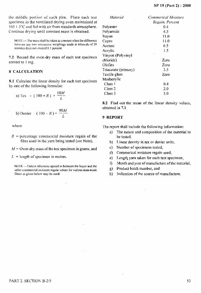
SP 15 (Part 2) :2000
the middle portion of each pirn. Place each testspecimen in the ventilated drying oven maintained at105 + 3°C and fed with air from standards atmosphere.
Continue drying until constant mass is obtained.
NOTE -– Tk mass shall bc taken as constant when the differencebetween any two successive weighings made at intervals crf20minotes does not exceed 0.1 percent.
7.2 Record the oven-dry mass of each test specimen
correct to 1 Ing.
8 CALCULATION
8.1 Calculate the linear density for each test specimenby one of the following fonmulae:
10A4a) Tex =(loo+f?)x~
90Mb) Denier =( IOO+R)X ~
where
A4aterial
PolyesterPolyamideRayon
CuproAcetateAcrylicVinyon (Polyvinylchloride)OIefinsTriacetate (primary)Textile glassModacrylicClass 1Class 2Class 3
Cotnmerical Moi.st~lre .:.-*
Regain, Percent 10.44.511.0
11.0
6.51.5
ZeroZero3.5
Zero
0.42.03.0
8.2 Find out the mean of the linear density values,obtained in 7.1.
9 REPORT
The report shall include the following information:
a)R = percentage commercial moisture regain of the
tlbre used in the yarn being tested (see Note), b)
M = Oven-dry mass of the test specimen in grams, and c)
d)L = length of specimen in metres. e)
NOTE — LJntessotherwise agreed to between the buyer and theo
seller commercial moistore regain values for various man-made g)
fibres m given below maybe osed: h)
The nature and composition of the material tobe tested,
Linear density in tex or denier units,I
Number of specimens tested,
Commerical moisture regain used,
Lengt~ yam taken for each test specimen,
Month and year of manufacture of the material, . .
Product batch number, and)
Indication of the source of manufacture. ;},.,~..
PART 2, SECTION B-2/5
/
53
SP 15 (Part 2) :2000
DETERMINATION OF UNIVERSAL
COUNT OF JUTE YARN
(Som-ce : 1S 570: 1964)
1 SCOPE
It is prescribes two methods for determination ofuniversal count ofjute yarn. The methods are applicableto single, plied or cabled yam.
NOIT — In the case of plied or cabled yarn, the methods areapplicable for determination of its resultant count.
2 PRINCIPLE
The first method is based on detemlining the universalcount of yam after conditioning the test specimens inthe standard atmosphere. The second method is basedon determining the weight of the specimen by drying itin a drying oven and calculating from this weight, itsconditioned weight by adding the moisture regain vahre.
3 SAMPLING
3.1 Lot
Quantity of jute yarn of one definite count and qualitydelivered to one buyer against one despatch note.
3.2 The conformity of a lot to a specification shall bedetermined on the basis of test carried out on the sampleselected from the lot.
3.3 Unless otherwise agreed upon between the buyerand the seller, the total number of baIes (or trusses) to betaken at random from a lot shall be in accordance withthe requirements of Table 1.
Table 1 Number of Bales or Trusses to be
Selected from the Lot
No. of Bales
(or Trusses)in a Lot
(1)
2 to 25
26 ,, 5051 ,, 75
76 ,, 100
Above 100
No. of Bales(or Trusses)to be Taken
(2)
I
234
3 percent of the additional bales
3.4 One bundle of yarn shall be drawn from each of thebales (or trusses) drawn as in Table 1. However, if the
number of bundles in a bale (or truss) is more than25, two bundles shall be drawn from each of the bales(or trusses) drawn.
3.5 In case the yarn is on cones, the number of cones tobe taken at random from the lot shall be in accordancewith the requirements of Table 2.
Table 2 Number of Cones to beSelected from the Lot
No. of Cones No. of Conesin tbe Lot to be Selected
(1) (2)
up to I00 2101 “ 150 3151 “500 5
501 “’I 000 81001 “3 000 13
3001 and above 20
3.6 From each of the bundles drawn as in 3.4 two skein,each 100 m long, shall be reeled off from different partsof the bundle, on a wrap reel with a girth of two metres.When being reeled, the yam shall be kept under sufficienttension to avoid kinks, curls and slacks in the yarn onthe one hand, and stretch on the other, operating the reelat a speed of 100 to 200 rev/rein. In case the yarn is oncones, one 100 m long skein shall be reeled off fromeach cone drawn as in 3.5. The skeins so reeled shallconstitute the test specimens.
3.6.1 In case the procedure prescribed in 3.6 providesless than 10 test specimens from the lot, further testspecimens shall be taken from the selected bundles orcones (see 3.4 and 3.5) to bring the number of testspecimens up to 10.
4 ATMOSPHERIC CONDITIONS FOR TESTING
4.1 The test prescribed in 7.2 shall be carried out in astandard atmosphere at 65 * 2 percent relat ive hum idityand 27 + 2°C temperature.
5 CONDITIONING OF SPECIMENS
5.1 When the test is to be carried out by the methodprescribed in 7.2 prior to evaluation, the test specimens
shall be left in the standard atmosphere at 65 + 2 percent
...-
,----
54 PART 2, SECTION B-2/6
..
i
relative humidity and 27+ 2°C temperature for48 hoursin such away as to expose, as far as possible, all portionsof the specimens to the atmosphere.
Ik 6 APPARATUS
For the purpose ofI
shall be used.I
6.1 Drying Oven
this test, the following apparatus
Ofa suitable capacity to hold about 500 g of yarn,
( preferably of the ventilated type with positively induceddraught, capable of maintaining an inside temperatureof 105 to 110° and provided with a balance whichweighs correct to O.1 g.
6.2 Pan Balance
With weights in grams and capable of weighing accurateto 0.1 g.
t7 PROCEDURE
7.1 Determine the universal count of yarn by the methodprescribed in 7.2 or 7.3 as agreed to between the buyerand the seller or as specified in the material specification.In case of dispute, however, the method specified in7.3 shall be followed.
7.2 First Method
7.2.1 Take one of the conditioned skeins (see 5.1)constituting the test specimens and weight it correct tothe nearest O.I g. Calculate its universal count in themanner prescribed in 8.
7.3 Second Method
7.3.1 Take a skein of yam constituting the test specimens
(see 3.5) and dry it to constant weight at 105 to 110”C inthe drying oven. Determine its constant weight. Stop
the draught through the oven during weighing. Take theweight to be constant when the difference between the
two consecutive weighings at an interval of20 minutesis lCSSthan O.] percent of the first weight.
N()’IT — In order to avoid risk in oil evaporation, the draught inthe (k}in: own shall not he crmtinucxlthroughout the dryingpmiod but 511:111hc in operation onl) intermittently.
7.3.2 Calculate the conditioned weight of the skein bythe formula given below:
PART 2. SECTION B-216
SP 15 (Part 2) :2000
A(1OO+R)Conditioned weight of the skein =
100
where
A = oven-dry weight, in g, of the specimen, andR = moisture regain value of 17 percent.
8 CALCULATION AND REPORT
8.1 Calculate the universal count of the test specimenusing the formula given below:
Universal count, in tex = %x 1000
where
W = weight, in g,, of the test specimen determinedeither as in 7.2.1 or 7.3.2; and
L = length, in m, of the test specimen.
8.2 Repeat the procedure prescribed in 7.2 or 7.3 withthe remaining test specimens in the sample and determinetheir universal count in tex.
8.3 Calculate the mean of all the values and report it asthe universal count, in tex, of the yarn in the lot. Reportalso the method followed for determining the universalcount.
9 CONVERSION OF GRIST INTO UNIVERSALCOUNT AND VICE-VERSA
9.1 For conversion of grist to universal count in tex, usethe following formula:
~ = ~ ~ 34.45
where
T,= universal count. in tex; and
~ = grist, in 1b.
9.2 For conversion of universal count to grist, use thefollowing formula:
? = T, x 0.029
where ~ and T, are same as in 9.1.
9.3 For convenience, Table 3 may, wherever possible,
be used for converting grist values into universal countin tex,
55
}.

SP 15 (Part 2) :2000
Table 3 Grist to Universal Count, in Tex
(Clause 9.3)
Grist o 10 20 30tcx tex tex tex
o — 3450.5 — 3601.0 . 3801.5 — 3952.0 — 415
2.5 85 430
3.0 105 4503.5 120 4654.0 140 4804.5 155 5(.X3
5.() 170 515
5.5 190 5356.0 205 5506.5 225 57137.0 240 585
7.5 260 605
8.0 275 6208.5 295 6359.0 310 655
9.5 325 670
NOTE — Tex values rounded c)ffto nearest 5 units,
690705725740760
775
790810825845
860
880895910930
945
9659801000
1015
1035————
——
—
————
———
I
#’
+
56 PART 2, SECTION B-2/6
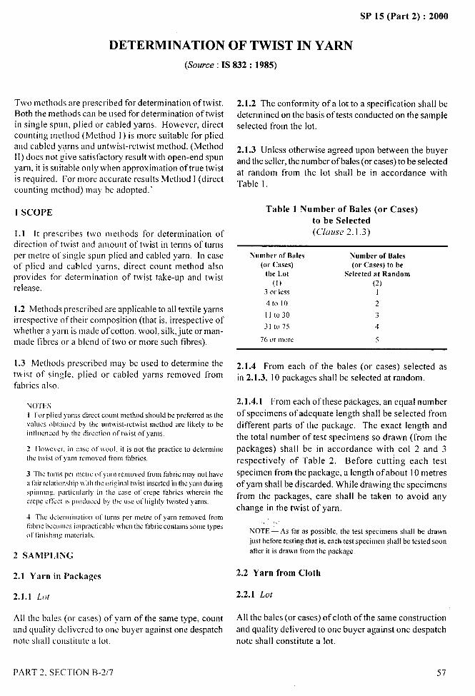
SP 15 (Part 2) :2000.-
DETERMINATION OF TWIST IN YARN
(Source : IS 832: 1985)
Two methods are prescribed for determination of twist. 2.1.2 The conformity of a lot to a specification shall beBoth the methods can be used for determination of twist determined on the basis of tests conducted on the samplein single spun, plied or cabled yarns. However, direct selected from the lot.counting method (Method I ) is more suitable for pliedand cabled yarns and untwist-retwist method. (Method 2.1.3 Unless otherwise agreed upon between the buyer11)does not give satisfactory result with open-end spun and the seller, the number of bales (or cases) to be selectedyarn, it is suitable only when approximation of true twist at random from the lot shall be in accordance withis required. For more accurate results Method I (direct Table 1.counting method) may be adopted.’
I SCOPE
1.1 It prescribes two methods for determination ofdirection of twist and amount of twist in terms of turnsper metre of single spun plied and cabled yarn. 10 caseof plied and cabled yarns. direct count method alsoprovides for determination of twist take-up and twistrelease.
1.2 Methods prescribed are applicable to all textile yarnsirrespective of their composition (that is, irrespective ofwhether a yarn is made of cotton, wool, silk, jute or man-made fibres or a blend of two or more sLIch fibres).
1.3 Methods prescribed may be used to determine thetwist of single, plied or cabled yarns removed fromfabrics also.
NOTES1 Ior plied ya!msdirect count method shoo]d be preferred as lbevdLIes oblained by the untwist-retwist method arc likely to beintlucnccd by the direction of twist of yarns.
2 1Io\ve\ cr. in case of ivoo!. it is not the practice to determinethe t\vist of yarn removwi from iidn-ics.
3 The tams per metm ~~fyarnremoved lkomfabric may not havea thir rclalinnsbip I\ i[llthe c)l-i:inalhvisl insertedillthe yarn duringspinning. particalwly in the use of crepe fabrics wbercin thecrcp$ etkct is prod[lccd by the usc of highly twisted yarns.
-t Tbc determination of turns per metrc of yarn removed fromf:,brlc(ICCC,111C5impractical~]cwlvmtbe thbl-iccontains SOOIClYPeS
(11’linisbing materials.
2 SAMPLING
2.1 Yarn in Packages
2.1.1 Lot
Table 1 Number of Bales (or Cases)to be Selected(c/ause 2.1 .3)
Nomber of Bales(nr Cases)
the Lot(1)
3 m less
4to 10
llto30
31 to 75
76 m more
Nrrmberof Ilalcs(or Cases) to be
Selected at Random(2)
I
2
3
4
5
2.1.4 Frotn each of the bales (or cases) selected asin 2.1.3, 10 packages shall be selected at randotn.
2.1.4.1 From each of these packages. an equal number
of specimens of adequate length shall be selected from
different parts of the package. The exact length and
the total number of test specimens so drawn (from the
packages) shall be in accordance with COI 2 and 3
respectively of Table 2. Before cutting each test
specitnen from the package, a length of about 10 metres
of yarn shall be discarded. While drawing the specimens
from the packages, care shall be taken to avoid any
change in the twist of yarn.
:.NOTE — As far as possible, the test specimens shall be drawnjust before testing that is, encb test specimen :ball be tested soonafter it is drawn tiom tbe package
2.2 Yarn from Cloth
2.2.1 Lot
All the bales (or cases) ofyu-n of the same type, count All the bales (or cases) of cloth of the satne construction
and quality delivered to one buyer against one despatch and quality delivered to one buyer against one despatch
note shall constitute a lot. note shall constitute a lot.
PART 2, SECTION B-X7 57
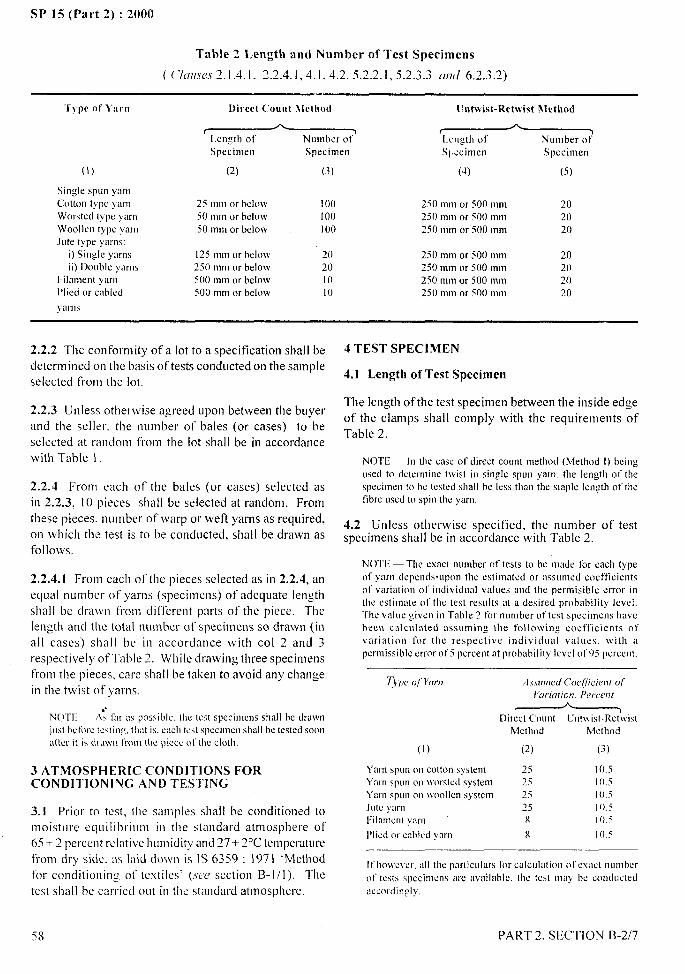
SP 15 (Pat-t 2) :2000
Table 2 Length and Number of Test Specimens
( C’ICII[,W,V2.1.4.1, 2.2.4.1, 4.1, 4,2, 5.2.2.1, 5.2.3.3 (llld6.2.3.2)
‘rypv Ot’l’arn l)irc~t {’ount N[ethod tlntwist-Retwist Nlcthrsd
~ ~.>= ‘=
Specimen Specimen Spccimcrr Specimen
(1) (2) (3) (4) (5)
Single spLm yarn
Cotton type yarn 25 mm or h~low 100 250 mm or 500 mm 20Worsted type yarn 50 mm or below I00 250 mm or 500 mm 20Woollcn type yam 50 mm or below 100 250 mm or 500 mm 20late type ya]ms:
i) ,Sin@ ymns 125 mm or h~low ~o 250 mm or 500 mm 20ii) Dooble yarns 250 mm or below 20 250 mm or 500 mm 20
FiIament yarn 500 mm or below lo 250 mm or 500 mmPlied or cabled
20500 mm or below lo 250 mm or 500 mm
yarns
20
2.2.2 The conformity of a lot to a specification shall bedeter-m ined on the basis of tests conducted on the sampleselected from the lot.
2.2.3 Unless otherwise agreed upon between the buyerand the seller, the number of bales (or cases) to beselected at random from the lot shall be in accordancewith Table 1.
2.2.4 From each of the bales (or cases) selected asin 2.2.3, 10 pieces shall be selected at random. Fromthese pieces. number of warp or weft yarns as required,on which the test is to be conducted, shall be drawn asfollows.
2.2.4.1 From each of the pieces selected as in 2.2.4, an
equal number of yarns (specimens) of adequate lengthshall be drawn from different parts of the piece. Thelength and the total number of specimens so drawn (inall cases) shall be in accordance with COI 2 and 3respectively of Table 2. While drawing three specimensfront the pieces, care shall be taken to avoid any changein the twist of yarns,
NOTI1— A: far as Ipossiblc.tl)c test specimens sha]l be drnwn
jLIst bcthre tinting. tlmt is. each teit specimen shall he tested soon
after it is dI Ll\wI from the piccc 0( (IICcloth
3 ATMOSPHERIC CONDITIONS FORCONDITIONING AND TESTING
3.1 Prior to test, the samples shall bc conditioned tomoisture equi[ibriunl in the standard atmosphere of65* 2 percent relative hulniclity and 27+ 2°C temperaturefrom dry side. as laid down is IS 6359: 197 i ‘Methodfor conditioning of textiles’ (we section B-1/1). Thetest shall he carried out in the standard atmosphere.
—.
,
4 TEST SPECIMEN
4.1 Length of Test Specimen
The length of the test specimen between the inside edgeof the clamps shall comply with the requirements ofTable 2.
NOTE— In the case ot’direct coont method (Method I) [IcingaSed tcl dckrminc twist in sing]e span yam. the length of thespecimen 10bc kstcd shall be less than tbe staple length of thetibre osed to spin lhc yarn.
4.2 Unless otherwise specified, the number of testspecimens shall be in accordance with Table 2.
NOTE — The exact nomber Of tests to be made lor each typeof ylrn depends.opon the eslinlatcd or tlSSLaIICdcoefficientsot’variation 01’inciividwd valoes and the permisiblc error inthe estimate of the test rcsal[s at a desired probability level.‘Ihc VdUC given in ‘rable 2 ror nomber of Lestspecimens tmvcbeen calculated assoming the following coefficients ofvariation for the respective individual valaes, with apermissible error of5 percent at probability Icvel of95 pcrceat.
T)y)e of Y(w)? Z1.w(nied<’ocfficientofI‘cIrl<ltlon,Pert’c’17[
Direct CoantMethod
()) (2)
Ymn span on cotton system 25Yam span on worskxl system 25Yarn span on Ivoollca system 25Jute )ara ?5Filmnent yam x
Plied or mblcd yin-n 8
[ lnt\vist-Ret\vistMctllod
(3)
105I 0.510.510.5]05
10.5
Ifhowcvcr, all the pw[icalars for calculation ot’exad namkrof tests specimens are availnblc. the tc$t may bc cond~lctcdaccordingly,
I
PART 2, SECTION B-2/7
,*.-
.-
SP 15 (Part 2) :2000
5 METHOD I DIRECT COUNT METHOD
5.1 Apparatus
The direct counting type twist tester shall conform tothe following requlrcments:
a) The twist tester shall be provided with:
i ) two clamps (or jaws) one rotatable and other non-
rotatable to grip the test specimens;
2) a scale graduated in centimetres and millirnetres
to measure the distance between clamps;
shape of central portion of the letters ‘,’7or ‘Z’.Note thedirection of twist as ‘S or ‘Z as observed.
5.2.2 Twist in .Tingle Yar/7
5.2.2.1 Set the clamps so that the distance between theclamps is equivalent to the applicable value of the lengthof test specimen specified in Table 2 and ensure that thedistance so set is within an accuracy of one percent of0.5 mm whichever is g-eater. Set the revolution counterto zero position. Set the tensioning device so as to applya tension of about tex/2 g + 10 percent (.wwNote) on thetest specimen.
3) a revolution counter positively connected to the rwm; — 11is ;Issumed tlmt tbe oniversal count, in tcx. of yarn
rotatable clamp and capable of recording theunder test would hc known md if not known W’OLIILI he ckterminedby !veigbing a kmnvn length ofymm ta!+mt’mm[be conditioned
number of revolutions of the clamps to an wmple. IH case ot’jote yarns a pretension ot’tcx/4g * IOpercentaccuracy OF may be oscd.
i) one turn, f’or testing specimen of length more 5.2.2.2 Secure the free end of the test specilmen in the
than 50 mm; non-rotatable clamp. Pass the other end of the specimenii) one tenth of a turn, for testing specimen of through the open rotatable clamp and pull it through the
length equal to or less than 50 mm and for clamp till the specified pre-tension becomes effective,
testing yarn with low twist; and then secure the specitnen.
4) a suitable scale, graduated in miliimetres tomeasure the elongation of contraction of the testspecimen; and
5) a suitable magnifyin~ glass to examine visuallythe test specimen during the test.
b) The distance bet\veen the clamps shall be capable ofbeing set to any distance up to 500 mtn as required.
c) The rotatable clamp shall be capable of being revolvedin either direction on its axis common to the longitudinal
axis of the test specimen.
d) The revolution counter shall be capable of being setto zero mark after each test.
e) The non-rotatable clamp shall be mounted on itssupport in such a manner that the required tension couldbe applied to tile test specimen.
5.2.2.3 Determine the direction of twist, ,’$or Z byvisually testing the specimens.
5.2.2.4 Revolve the rotatable clamp in the proper
direction so as to untwist the specitnen. Continue therotation in the same direction until it is possible to pass aneedle from one clamp lo the other between the untwistedfibre of the specimen; use the tnagnifying glass, ifnecessary, to make sure that all the twist has beenremoved. Note down the number of turns.
5.2.2.5 From the value obtained 5.2.2.4 and the length
oftbe test specimen before untwisting. calculate the turnsper metre in the test specimen.
5.2.2.6 By following the procedure 5.2.2.1 to 5.2.2.5
determine the turns per metre in the remaining testspecimens. Calculate the mean of all the values soobtained and the coefficient of variation.
5.2.3 T\~ist in Plied Yarn
5.2 Procedure
Hold one end of’ the yarn in such a position that a shortlength (at least 100 mm) is suspended in a verticalposition. Examine tllc vertical section of the yarn anddetermine if the shape of yarn elements conform to the
5.2.3.1 Detet-ming the direction of twist and thenumber of turns in the test specimens by followingthe procedure prescribed in 5.2.2.1 to 5.2.2.4 butnoting. for the purpose of 5.2.2.4 the end-point of thetest when it is possible to pass a needle betweencomponent yarns of’ the specimen. Record also theextension in length obtained on unt\visting the testspecimen.
-----$
,!\
,,
59PART 2. SECTION B-2/7
I1! I
I
SP 15 (Part 2) :2000
,4-
5.2.3.2 From the value of number of turns obtainedin 5.2.3.1 and the length of the specimen before untwist-ing, calculate the turns per metre in the test specimen.
5.2.3.3 Cllt off all but one component stand of single
yarn close to the inside edges of the clamps. Test thecomponent stand (still in the clamps) of single yarn for
the direction of twist and the number of turns by
following the p?ocedttre given under 5.2 and 5.2.2 butadjusting the length ofthe test specimen to comply with
the requirements of Table 2.
NOTE — 11is assormxithat all the component single yarns havethe same amnunt ofllvist. Ifthis fact is not known, it shoa]d beveritied. 1! it is found that they differ in respect of the amoont(It’t\vist. each component yarn shall bc tested and the resultsreporteci.
5.2.3.4 Test similarly the remaining test specimens for
turns per metre of the plied yarn and the component singleyarns, and twist take-up and twist-release of plied yarn.
Calculate the mean of all the values so obtained and thecoefficient of variation of the values.
5.2.4 T}iis{ ill C’abled Yu1-t7
5.2.4.1 Determine the direction of twist, and the numberof turns in the test specimens by following the procedureprescribed in 5.2.2.1 to 5.2.2.4 but noting, for the purposeof 5.2.2.4 the end point of the test when it is possible topass a needle between the strands of the component pliedyarn of the specimen. Record also the extension in lengthobtained on untwisting the test specimen.
5.2.4.2 From the value of number of turns’ obtained
in 5.2.4.1 and the length of the specimen before
untwisting, calculate the turns per metre in the testspecimen.
5.2.4.3 Cut off all but one component strand of the plied
yarn, close to the inside edges of the clamps. Test thecomponent strand of plied yarn for the direction of twistand the number of turns per metre, in the plied andcomponent single yarns (still in the clamps) by followingthe procedure given in 5.2.3.
NOTE — It is assomcxtthat all [he component plied yarns havethe sao-wanwont of[wist If this fact is not known, it should bevcriticd. If it is fcmnd[hat they differ in respect of the amoont oftwist. cac+ componentyarn shall be tested and the resoltsreported.
5.2.4.4 Test similarly the remaining test specimens forturns per metre of the cabled yarn, of the componentplied yarns, and of the component single yarns; the twisttake-up and twist-release of cabled yarn and of plied yarn.
60
Calculate the mean of all the valued so obtained and thecoefficient of variation of turns per rnetre values.
6 METHOD 11 UNTWIST-RETWIST METHOD
6.1 Apparatus
The untwist-retwist type of twist tester shall conform tothe following requirements:
a) The twist tester shall be provided with:
1)
2)
~)
4)
5)
6)
7)
b)
c)
d)
e)
o
g)
1
1
a pair of jaws - the rotatable and other non-rotatable 9 (called movable) - to hold the specimenof yarn by each of its extremities;a revolution counter positively connected torotatable jaw and capable of recording the numberof revolution of the jaw;means of a sliding support so that the distancebetween the jaws may be adjustable in order topermit measurements of the length of yarn;a scale graduated in centimetre and mill imetre tomeasure the distance between the jaws;means shall be provided either by dead weight or
by displacement of vertical penduhun for applyingtension to the specimen and maintaining thattension until permitted elongation is obtained;means shall also be provided for rapidlydetermining the specimen length to an acuracy of+ 0.5 mm; and
means shall also be provided to prevent specimen
under test extending more than 2 percent, forexample by means of stop.
Rotatable jaw may be motor driven or hand drivenit speed in excess of 820 turns per minute;~ovable jaw, situated in the extension of the arm
of rotatable jaw is mounted so that it is capable of~eing displaced and stopped in tile direction of thisaxis;Movable jaw shall not be able to be turned about itsown axis;The sliding support shall not permit play affectingthe length of test specimen:The distance between the jaws shall be capable of
being set to any distance as required; andRevolution counter shall be capable of being set tozero mark after each test.
6.2 Procedure
6.2.1 Direction of Twist
Determine the direction of twist in the yarn by theprocedure mentioned at 5.2.1.
PART 2, SECTION EI-2/7
‘t
/
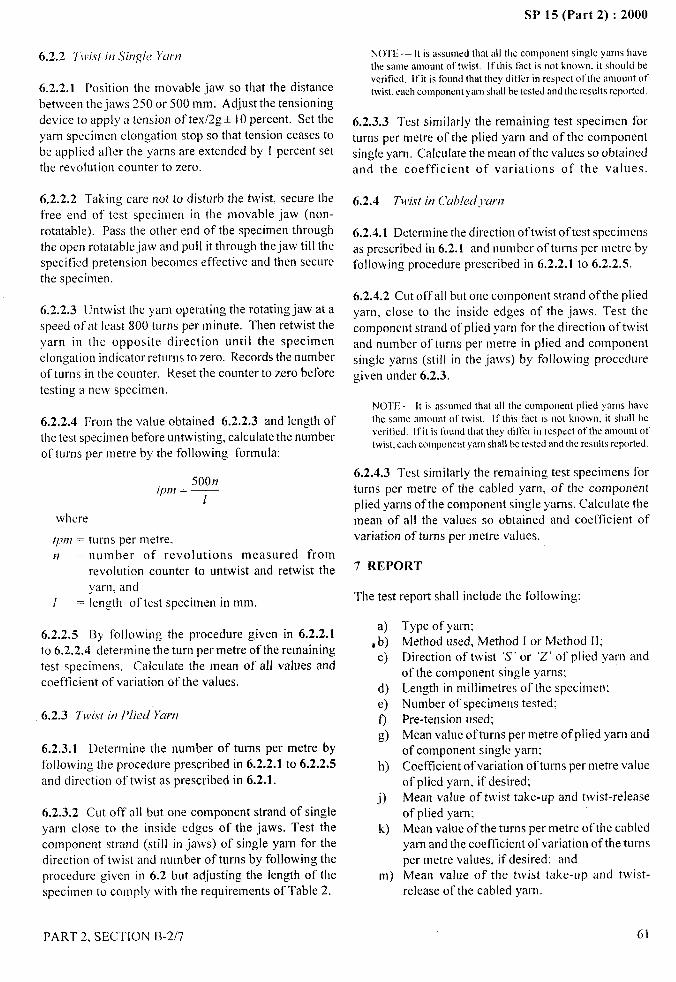
6.2.2 TIvis[ i)~Sii7,q/e Yurtl
6.2.2.1 Position the movable jaw so that the distance
between the jaws 250 or 500 mm. Adjust the tensioningdevice to apply a tension of tex/2g* 10 percent. Set theyarn specimen elongation stop so that tension ceases tobe applied after the yarns are extended by 1 percent setthe revolution counter to zero.
6.2.2.2 Taking care not to disturb the twist, secure thefree end of test specimen in the movable jaw (non-
rotatable), Pass the other end of the specimen throughthe open rotatable jaw and pull it through the jaw till thespecified pretension becomes effective and then securethe specimen.
6.2.2.3 Untwist the yarn operating the rotating jaw at aspeed of at least 800 turns per minute. Then retwist the
yarn in the opposite direction until the specimenelongation indicator returns to zero. Records the numberof turns in the counter. Reset the counter to zero beforetesting a new specimen.
6.2.2.4 From the value obtained 6.2.2.3 and length ofthe test specimen before untwisting, calculate the numberof turns per rnetre by the following formula:
50017tpm = —
1
where
/pm = turns per metre,n = number of revolutions measured from
revolution counter to untwist and retwist the
yarn, and[ = length of test specimen in mm.
6.2.2.5 By following the procedure given in 6.2.2.1to 6.2.2.4 determine the turn per metre of the remainingtest specimens. Calculate the mean of all values andcoefficient of variation of the values.
6.2.3 TJvi.st in Plied “Yarn
6.2.3.1 Determine the number of turns per metre byfollowing the procedure prescribed in 6.2.2.1 to 6.2.2.5
and direction of twist as prescribed in 6.2.1.
6.2.3.2 Cut off all but one component strand of singleyarn close to the inside edges of the jaws. Test thecomponent strand (still in jaws) of single yarn for thedirection of twist and number of turns by following theprocedure given in 6.2 but adjusting the length of thespecimen to comply with the requirements of Table 2.
SP 15 (Part 2) :2000
NOTE — 11is assLaned that all the component single yarns have
the same mroont dtwist. [f (his fact is not known. il shrrLItd beveritiwt. Ifit is foand that tlwy dit’tiirin respect ot”thc anmoot oftwist. each component yarn shall he tested and the resolts repcrrtcd.
6.2.3.3 Test similarly the remaining test specimen forturns per metre of the plied yarn and of the componentsingle yarn. Calculate the mean of the values so obtainedand the coefficient of variations of the values.
6.2.4 Twist in Culded]Iam
6.2.4.1 Determine the direction of twist of test specimensas prescribed in 6.2.1 and number of turns per metre byfollowing procedure prescribed in 6.2.2.1 to 6.2.2.5.
6.2.4.2 Cut off all but one component strand of the pliedyarn, close to the inside edges of the jaws. Test thecomponent strand of plied yarn for the direction of twistand number of turns per metre in plied and cotnponentsingle yarns (still in the jaws) by following proceduregiven under 6.2.3.
NOTE — It is assomcd that all the component plied yams have(IK same arnoont ot’twist, It’this fact is not known, it shall beveriiicd. lfit is tbond that they dit’ferin respect ofthc amooot oftwist, each cmnponcntyam shall be tested and the resohs reported.
6.2.4.3 Test similarly the remaining test specimens forturns per metre of the cabled yarn, of the componentplied yarns of the component single yarns. Calculate themean of all the values so obtained and coefficient ofvariation of turns per metre values.
7 REPORT
The tesl
a). b)
c)
d)e)
0/3)
h)
j)
k)
m)
report shall include the following:
Type of yarn;Method used, Method I or Method 11;Direction of twist ‘S’ or ‘Z’ of plied yarn andof the component single yarns;Length in miilimetres of the specimen:Number of specimens tested;Pre-tension used;Mean value of turns per metre of plied yarn andof component single yarn:Coefficient of variation of turns per metre valueof plied yarn, if desired;Mean value of twist take-up and twist-releaseof plied yarn;Mean value of the turns per metre of the cabledyarn and the coefficient of variation of the turnsper metre values, if desired; andMean value of the twist take-up and twist-
release of the cabled yarn.
PART 2. SECTION B-2/7 61

SP 15 (Part 2) :2000
DETERMINATION OF YARN STRENGTH PARAMETERS
OF YARNS SPUN ON COTTON SYSTEM
(~02/~C~ : 1S 1671: 1977)
t SCOPE
1.1 It prescribes methods for determination of yarnstrength parameters of yarns spun on cotton system usingcotton count and tex system.
1.1.1 In cotton count system, determination of leabreaking load and count strength product (CSP) havebeen prescribed and in the metric system, determinationof skein breaking load, yarn strength index (YSI) andskein breaking tenacity (SBT) have been prescribed.
2 SAMPLING
The samples shall be drawn in accordance with theprocedure laid down in IS 3920:1985 ‘Methods forsampling of cotton yarn for determination of physicalcharacteristics’ (see Section A-1 /1).
3 ATMOSPHERIC CONDITIONS FORCONDITION1NG AND TESTING
3.1 The samples shall be conditioned to moistureequilibrium in standard atmosphere of 65 + 2 percentrelative humidity and 27 + 2°C temperature [see also1S 6359 : 1971 ‘Method for conditioning of textiles’given in Section B-1/1].
3.2 The test shall be carried out in the standardatmosphere (see 3.1 ).
4 APPARATUS
4.1 Testing Machine
A skein breaking load testing machine working onconstant rate-of-traverse (CRT) principle. Its rate oftraverse shall be 300* 15 mmhnin and the load range of
the machine shall be such that the observed values wouldlie between 10 and 90 percent of the full scale load. Thepermissible error in the machine at any point in this rangeshall not exceed * I percent.
4.1.1 The machine shall be provided with the followingarrangements:
a) Two pulleys or hooks for holding the skein with
62
sufficient space to allow the even distribution ofthreads without much overlapping.
b) Means for adjusting distance between the pulleysor hooks.
c) A scale or dial or autograph recording chartgraduated so as to give load in kilograms.
4.2 Wrap-Reel
Having a girth of 1.372m (1 .5yd) or 1 m and capable ofreeling known length of yarn (see Annex A).
4.3 Yarn Tensioning Device
An adjustable tensioning device capable of giving areeling tension that will result in skeins of the specifiedlength when measured on a skein gauge. The adjustmentin reeling tension maybe made, for example, by makingmore than one wrap around thread guides or by passingthe yarn around tensioning bars. The reeling tension shallbe the same at all reeling positions and maybe checkedas follows:
The yarn is wound from the same package at differentreeling positions. The length of the skeins whenmeasured on a skein gauge shall not differ by more than0.1 percent.
4.4 Skein Gauge
A gauge for checking the length of the skein under aload of 0.5 gf/tex (5 mN/tex) and expressing the lengthas a plus or minus deviation frolm the nominal length.The sensitivity of the skein gauge shall be sufficient topermit rejection of skeins falling outside+ 0.25 percenttolerances. The skein-gauge length may be adjustable ornon-adjustable. A non-adjustable skein gauge can be usedwhen its nominal length differs by no more than0.4 percent from the measured perimeter of the reel.
NOTE — For details of skeiu gauge (see Anaex B).
5 PREPARATION OF TEST SPECIMENS
5.1 Prepare skeins of 109.73 m (120 yd ), 100 m or 50m as required, following the procedure as described inAnnex A.
PART 2, SECTION B-2/8
—7
--~“
‘\,.1%,/, ,
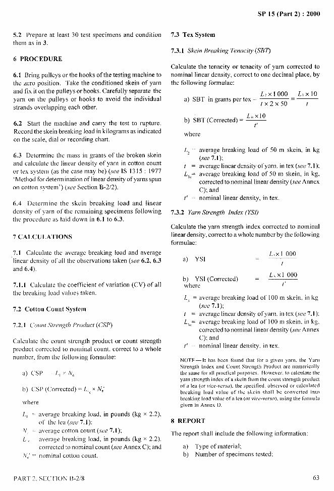
5.2 Prepare at least 30 test specimens and conditionthem as in 3.
6 PROCEDURE
6.1 Bring pulley sorthehooks of thetesting rnachinetothe zero position. Take the conditioned skein of yarnand fix it on the pulleys or hooks. Carefully separate the
yarn on the pulleys or hooks to avoid the individualstrands overlapping each other.
6.2 Start the machine and carry the test to rupture.Record the skein breaking load in kilograms as indicatedon the scale, dial or recording chart.
6.3 Determ ioe the mass in grams of the broken skeinand calculate the linear density of yarn in cotton countor tex system (as the case may be) (see IS 1315 : 1977‘Method for determination of linear density of yarns spunon cotton system’) (see Section B-2/2).
6.4 Determine the skein breaking load and lineardensity of yarn of the remaining specimens followingthe procedure as laid down in 6.1 to 6.3.
7 CALCULATIONS
7.1 Calculate the average breaking load and average‘linear density of all the observations taken (see 6.2, 6.3and 6.4).
7.1.1 Calculate the coefficient of variation (CV) of allthe breaking load values taken.
7.2 Cotton Count System
7.2.1 C’071)71 S[rmgth Product (CSP)
Calculate the count strength product or count strengthproduct cor-rected to nominal count, correct to a wholenumber, from the following fOrmLdae:
a) CSI’ =L,x~e
b) CSP (Corrected)= Ll, x NJ
where
L = average breaking load, in pounds (kg x 2.2),of the lea (see 7.1);
NC L average cotton count (see 7.1);
L,, average breaking load, in pounds (kg x 2.2),
corr-ected to nominal count (see Annex C); and,N,’‘- nominal cotton count.
SP 15 (Part 2) :2000
7.3 Tex System
7.3.1 Skein Breaking Terraci@ (SBT)
Calculate the tenacity or tenacity of yarn corrected tonominal linear density, correct to one decimal place, bythe following formulae:
L2X1OOO L2x1Oa) SBT in grams per tex =
tx 2x50= t
L,. x1Ob) SBT (Corrected)= —
t’
where
L, =
t=
L,c=
t’ =
average breaking load of 50 rn skein, in kg(see 7. I );average linear density of yarn, in tex (see 7.1):average breaking load of 50 rn skein, in kg,corrected to nominal linear density (see AnnexC); andnominal linear density, in tex.
7.3.2 Yarn Strength Index (YSI)
Calculate the yarn strength index corrected to nominallinear density, correct to a whole number by the followingformulae:
a) YSILxl 000
t
~~lle~SI (Corrected) =L,. xl 000
t’
L, =
t=
L,C=
t’ =
average breaking load of 100 rn skein, in kg
(see 7.1);average linear density of yarn. in tex (see 7. I ):average breaking load of 100 rn skein, in kg.corrected to nominal linear density (see AnnexC); andnominal linear density, in tex.
NOTE— It has been foond (hat for a given ymo. the YamStrength Index and Cooot Strength Product me namericzdlythe same for all practical purposes. However. to calculate theyaro strength index of a skein from the cooot strength prodoctofa lea (01-vice-versa). the specitied. observed or c:dcalatedbreaking load vzdoe of the skein shall be convcrred intobreaking load value ot’a lea (or vice-wr.w). osing the formalagiveo in Annex D.
8 REPORT
The report shall include the following information:
a) Type ofrnaterial;b) Number of specimens tested;
PART 2, SEC’T1ON B-2/8 63
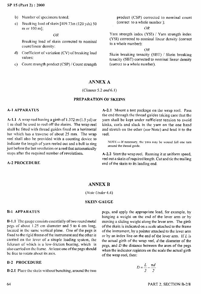
i
SP 15 (Part 2) :2000t. --—
b) Number of specimens tested;
c) Breaking load of skein [109.73m (120 yds) 50
m or 100 m];
OR
Breaking load of skein corrected to nominalcount/linear density;
d) Coefficient of variation (CV) of breaking loadvalues;
e) Count strength product (CSP) / Count strength
product (CSP) corrected to nominal count
(correct to a whole number);
OR
Yarn strength index (YS1) / Yarn strength index(YSI) corrected to nominal linear density (correctto a whole number);
OR
Skein breaking tenacity (SBT) / Skein breakingtenacity (SBT) corrected to nominal linear density
(correct to a whole number).
ANNEX A
(Clauses 5.2 and 6.1)
PREPARATION OF SKEINS
A-2 PROCEDURE
A-1 APPARATUS
A-1.1 A wrap reel having a girth of 1.372 m (1.5 yd) orI m shall be used to reel off the skeins. The wrap reelshall be fitted with thread guides fixed on a horizontalbar which has a traverse of about 25 mm. The wrapreel shall also be provided with a counting device to
indicate the length of yarn reeled out and a bell to ringjust before the last revolution or a reel that automaticallystops after the required number of revolutions.
A-2.1 Mount a test package on the wrap reel. Passthe end through the thread guides taking care that theyarn shall be kept under sufficient tension to avoidkinks, curls and slack in the yarn on the one handand stretch on the other (see Note) and lead it to thereel.
NOTE— It’oecessary. the yarn may be woLIndfLIllone tumaround the thread goide.
A-2.2 Start the wrap reel. Running it at uniform speed,reel out a skein of required length. Cut and tie the trailing
end of the skein to its leading end.
ANNEX B
(Note Under 4.4)
SKEIN GAUGE
B-1 APPARATUS
B-1. 1 The gauge consists essentially of two round metalpegs of about 1.25 cm diameter and 5 to 6 cm long,located in the same vertical plane. One of the pegs isfixed to the rigid frame of the instrument and the other iscarried on the lever of a simple loading system, thefulcrum of which is a low-friction bearing, which isalso carried on the frame. At least one of the pegs shouldbe free to rotate about its axis.
B-2 PROCEDURE
B-2.1 Place the skein without bunching, around the two
64
pegs, and apply the appropriate load, for example, byhanging a weight on the end of the lever arm or bymoving a sliding weight along the lever arm. The girthof the skein is indicated on a scale attached to the frameof the instrument, by a pointer attached to the lever armor by an index line on the end of the lever arm. If L. isthe actual girth of the wrap reel, d the diameter of thepegs, and D the distance between the axes of the pegswhen the indicator registers on the scale the actual girthof the wrap reel, then:
~=L rcd
22
PART 2, SECTION B-2/8 tI
/
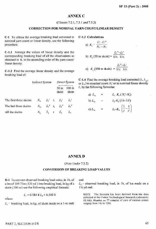
&-
.-
SP 15 (Part 2) :2000
ANNEX C
(Clauses 7.2.1,7.3.1 and7.3.2)
CORRECTION FOR NOMINAL YARN COUNT/LINEAR DENSITY
C-1 To obtain the average breaking load corrected tonominal yarn count or linear density, use the followingprocedure.
C-1.1 Arrange the values of linear density and the
corresponding breaking load of all the observations asobtained in 6, in the ascending order of the yam count/linear density.
C-1.2 Find the average linear density and the averagebreaking load OE
[rrdirect System Direct System
50m 100mskein skein
The first three skeins N,, L,’ t, L; L,’
The last three skeins N., L}” tz L;, L,!,
All the skeins N. L, t L, L,
C-1.3 Calculations
L,’–L,”
a) ‘~ = NC,– N,,
L2’’–L2’
b) Kz (50 m skein) = I/t,I/t,
L,’’–L,’
C) K, (100 m skein) = l/t, l/t,
C-1.4 Find the average breaking load corrected (L, L,C,
or L~C)to nominal count NJ or to nominal linear densityt’,by the following formulae:
a) L(C = L,-K, ( N;-NC)
b) L,c = L,-K, (l/t–l/t’)
C) L,c ——()
L,–K, ~ – ;
ANNEX D
(Note Under 7.3.2)
CONVERSION OF BREAKING LOAD VALUES
D-1 To convert observed breaking load value, in 1b, of and
a lea of 109.73m (120 yd ) into breaking load, in kg of a L2= observed breaking load, in 1b, of lea made on a
skein (100 m) use the following empirical formula: 1X yd reel.
L, = 0.5848 L,+ 0.5000 NOTE—The formula has been derived from the data
wherecollected at the Cotton Technological Research Laboratory(ICAR). Mumbai on 77 samples of yarn of various counts
L, = breaking load, in kg, of skein made on a 1-m reel; ranging from 14s to 120s.
PART 2. SECTION B-2/8 65
I
~ I
I
SP 15 (Part 2) :2000
DETERMINATION OF BREAKING LOAD AND
ELONGATION AT BREAK OF SINGLE STRAND
(Source: IS 1670: 1991)
I SCOPE
1.1 It prescribes procedure for determination of breakingload and elongation at break of yarn using constant-rate-
of-traverse, constant-rate-of-loading and constant-rate-of-extension machines. Since for any tibre type breakingload is approximately proportional to the linear density,
strands of different sizes are compared by convertingthe observed breaking load to breaking tenacity(centinewtons or millinewtons per tex).
1.1.1 The method prescribed is applicable tomonotilaments and multifilament other than tyre cordsand industrial yarns, and spun yarns (single, plied orcabled) made from all kinds of textile fibres of theirblends with the exception of yarns that stretch more than5.0 percent when tension is increased from 0.5 to 1.Og(5 to 10mN) per unit linear density of the yarn in tex.
1.1.2 This method is designed primarily for yarn inpackage form but can be used for single strands removed/extracted from a woven/knitted fabric.
1.1.3 This method does not cover textured yarns andfancy yarns.
1.1.4 This test method offers two options with respectto moisture content of the specimens at the time of testing.
1.1.4.1 Opfion 1
Conditioning to moisture equilibrium in the standardatmosphere for testing textiles (see IS 6359:1971 givenin Section B-l/l).
1.1.4.2 Option 2
Testing in wet condition. Tests on wet specimens are
usually made only on yarns which show a less strengthwhen wet or when exposed to high humidity, for
example, yarns made from animal fibres and man-madefibres based on regenerated and modified cellulose. Wettests are made on flax yarns to detect adulteration byfailure to gain strength.
1.1.5 This method also offers three options for thephysical confirmation of the specimen.
66
1.1.5.1 Option A — Straight (see Note 4).1.1.5.2 Option B — Knotted (see Notes 1,2 and 3),1.1.5.3 Option C — Looped (see Notes 1 and 3).
NOTES1 The reduction in strength due to the presence of a knot orloop is considered a measure of brittleness of yarn. If a textileyarn is looped or knotted, its tensile strength may reduce. Thiscan arise when a yarn is bent to a small radius ofcuvature (as insewing or knitting) or knotted (as in the manufacture of nets).In order to assess the importance of these effects, loop strengthand knot strength are described.
2 The knot strength test as described in this method is notintended to assess the effciency of any given type of knot forjoining together two separate lengths of yarns.
3 Elongation in a knot or loop test is not known to have anysignificance and is not usually recorded.
4 Unless otherwise indicated, ‘single-strand strength’ isassumed to refer to a straight, contltioned specimen (see 1.1.4.1and 1.1.5.1).
2 PRINCIPLE
The specimen is gripped between two clamps of thetensile testing machine and continually increasing loadis applied longitudinally by moving one of the clampsuntil the specimen ruptures. Values of the breakingload and elongation at break of the test specimen areread directly or from a chart attached.
3 TERMINOLOGY
For the purpose of this method, the following definitionsshall apply.
3.1 Elongation (or Extension) at Break
In a tensile test, the difference between the length of astretched specimen at breaking load and its initial lengthusually expressed as percentage of the latter.
3.2 Elongation at Rupture
The elongation occurring at the final rupture of thespecimen. The elongation at rupture is usually but notalways, identical with the elongation at the breaking load.
3.3 Knot Breaking Load
,I
!“ -
The breaking load of a strand with a knot tied in theportion of the specimen between the clamps.
PART 2, SECTION B-2/9
SP 15 (Part 2) :2000
3.4 Loop Breaking Load
The breaking load ofa specimen consisting of two lengthof yarn or monofi lament from the same package loopedtogether so that one length has both its ends in one clamp
of the testing machine and the other length has both itsends in the other clamp.
3.5 Single-Strand Breaking Load
The breaking load of a single strand of yarn,monofilament or cord, not knotted or looped but runningstraight between the clamps of the testing Imachine.
4 SAMPLING
The sample shall be drawn according to the proceduregiven in the relevant material specification or as agreed
to between the buyer and seller.
5 COND1TION[NG OF TEST SPECIMENS
until they are tbroughly soaked and sink under theirown weight. The time of immersion must be
sufficient to wet out the specimens thoroughly. The
time period will be at least 2 minutes for regeneratedcellulose yarn and at least 10 minutes for acetate.For yarns that do not readily wet with water, such as
those treated with water repellent or water-resistantmaterials, add a O. 1 percent solution of a nonioinicwetting agent to the water-bath. Do not use any agent
that will affect the physical properties of the yarn
appreciable. If a wetting agent has been used, the
specimen must be throughly rinsed in distilled or
demineralized water before conducting the test.When using option 2B, tie the knots very loosely
before wetting in order to save time and to avoid
handling while transferring the specimens from
container to the testing machine.
6 APPARATUS
6.1 Testing Machine
5.1 Option 1: Conditioned Specimens A single-strand tensile testiag machine working on oneof the following principles:
5.1.1 Prior to test, the specimens shall be conditioned tomoisture equilibrium in the standard atmosphere of65 +2 percent relative humidity and 27+2°C a) Constant-rate-of traverse (CRT),
temperature [(see 1S 6359 : 1971 ‘Methods of b) Constant-rate-of loading (CRL), and
conditioning of textiles’) (see Section B-l/l )]. c) Constant-rate-of-extension (CRE).
5.1.2 When the test specimens have been exposed to 6.1.1 It may be noted that, in most cases the resultsstandard atmosphere for at least as much time as given obtained on one type of machine will differ from thosebelow in such a way as to expose as far as possible, all obtained on another type and the three types of testingportions of the specimens to the atmosphere, they shallbe deemed to have reached moisture equilibrium:
machinej will not necessarily given the same results forany given yarn.
Equili[]rium Moisture Regain Value Time 6.1.2 Breaking load decreases slightly as the time-to-ojthe Yww at Stmdurd hours break increases. The rate of change is approximately of
Atmosp17ere the order of 5 to 10 percent decrease in the breaking
Percent load for a ten-fold increase in the time to break. It is
Less than 4 6 assumed that by testing with a specified time-to-break,
From 4 to 10 12t024 any difference between the results is reduced to a
Above 10 24 to 48 minimum.
5.1.3 The test shall be carried OLlt in standard atmosphere 6.1.3 The specimens shall break within 20* 3 seconds
(see 5.1.1). in the case ofconstant-rate-of loading and constant-rate-
of-extension machines. In the case of constant-rate-of-
5.2 option 2: Wet Specimens traverse machines, the rate of traverse shall be 300* 15mm/min and the load range of the machine shall be such
Reel a short skein from each of the packages forming that the observed value lies between 10 and 90 percent
the test sample. Clamp a group of specimens by both of the full scale load. The permissible error in the
ends to prevent loss of twist and submerge them in machine at any point in this range shall not exceed + I
distilled or demineralised water at room temperature percent of the load.
~ .....“1
PART 2, SECTION B-2/9 67
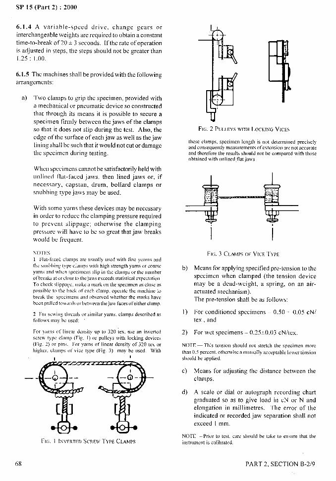
SP 15 (Part 2) :2000
6.1.4 A variable-speed drive, change gears orinterchangeable weights are required to obtain a constanttime-to-break of 20 * 3 seconds. If the rate of operationis adjusted in steps, the steps should not be greater thanI .25 :1.00.
6.1.5 The machines shall be provided with the followingarrangements:
,
a) Two clamps to grip the specimen, provided witha mechanical or pneumatic device so constructedthat through its means it is possible to secure a
specimen firmly between the jaws of the clampsso that it does not slip during the test. Also, the
edge of the surface of each jaw as well as the jawlining shall be such that it would not cut or damagethe specimen during testing.
..\.
FIG. 2 PULLEYSWITH LOCKING VICES
these clamps. specimen length is not determined preciselyand conscquent]ymeiuorements olextensioo are not accorateand therefore the resolts shoold not be colmparcdwith dmseobtained with oolioed tlatjaw’s
When specimens cannot be satisfactorily held withunlined flat-faced jaws, then lined jaws or, ifnecessary, capstan, drum, bollard clamps orsnubbing type jaws may be used.
IWith some yarns these devices may be necessary
in order to reduce the clamping pressure required
to prevent slippage; otherwise the clamping
pressure will have to be so great that jaw breaks
would be frequent. INOTI’S1 Flat-faced clamps arc usoally osed with tine ycams andthe snubbing type clamps with high strength yams 01-coarseyams and when spccinvms slip ill the clamps or the nomhel-olbreaks at orclose (L) thejaw exceeds statistical expectation,To check slippage, ma!ic a mark on the specimen as close aspossible to the back of each clamp, operate the macbioc iobreak the spccimeos and observed whether the marks havebeen polled towards or betiveea tbejaw faces of either clamp
FIG. 3 CLAMPSOF VICE I’YPE
1“ “--‘!,
‘\~,,~ij.,?
b) Means for applying specified pre-tension to thespecimen when clamped (the tension devicemay be a dead-weight, a spring, on an air-actuated mechanism).The pre-tension shall be as follows:
1) For conditioned specimens – 0.50 + 0.05 cN/tex., and
2 For smving tbrcads or similar yarns. clamps described asfbll[~\!’sIll:lybc ascd:
For yarns of [ioear density LIp to 320 ;ex, ase an inverted
scrm type clamp (Fig, I) or polleys with locking devices(Fig. 2) or pins. For yams of linear density of 320 tex orhigher. clamps of ~ricctype (Fig. 3) may be osed. With
I
2) For wet specimens – 0.25*0.03 cN/tex.
NOTE — This tension shoLIid not stretch dle specimen morethan 0.5 percent, otherwise a tnutu:dly acceptable lower tensionshoald be applied.
c) Means for adjusting the distance between theclamps.
A scale or dial or autograph recording chartgraduated so as to give load in CN or N andelongation in millimetres. The error of theindicated or recorded jaw separation shall notexceed 1 mm.
—.
d)
NOTE — Prior to test, care should be take to eosure that theinstrument is calibrated.FIG. I INV~RTIII SCRFWTYPE CLAMPS
68 PART 2, SECTION B-2/9
/
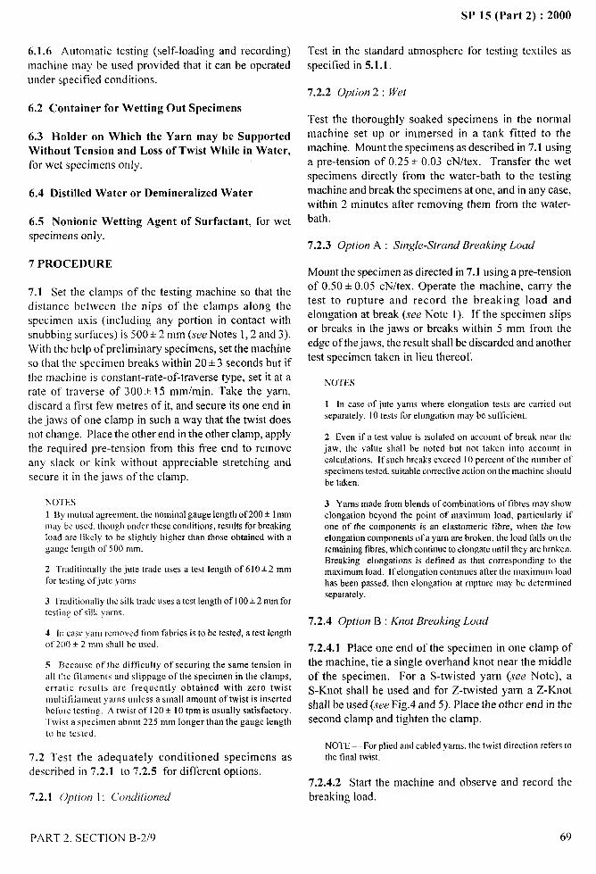
SP 15 (Part 2) :2000 _.. ..—
6.1.6 Automatic testing (self-loading and recording)machine may be used provided that it can be operated
under specified conditions.
6.2 Container for Wetting Out Specimens
6.3 Holder on Which the Yarn may be SupportedWithout Tension and Loss of Twist While in Water,for wet specimens only.
6.4 Distilled Water or Demineralized Water
6.5 Nonionic Wetting Agent of Surfactant, for wetspecimens only.
7 PROCEDURE
Test in the standard atmosphere for testing textiles as
specified in 5.1.1.
7.2.2 Option 2: Wet
Test the thoroughly soaked specimens in the normalmachine set up or immersed in a tank fitted to themachine. Mount the specimens as described in 7.1 usinga pre-tension of 0.25 * 0.03 cN/tex. Transfer the wetspecimens directly from the water-bath to the testingmachine and break the specimens atone, and in any case,within 2 minutes after removing them from the water-
bath.
7.2.3 Option A : Single-Strand Breaking Load
Mount the specimen as directed in 7.1 using a pre-tension
7.1 Set the clamps of the testing machine so that the of 0.50 + 0.05 cN/tex. Operate the machine, carry the
distance between the nips of the clamps along the test to rupture and record the breaking load and
specimen axis (including any portion in contact withelongation at break (see Note I). If the specimen slips
snubbing surfaces) is 500+2 mm (.we Notes 1,2 and 3).or breaks in the jaws or breaks within 5 mm from the
With the help of preliminary specimens, set the machineedge of thejaws, the result shall be discarded and another
so that the specimen breaks within 20+3 seconds but iftest specimen taken in lieu thereof.
the math ine is constant-rate-of-traverse type, set it at a NOTESrate of traverse of 300+ 15 mm/min. Take the yarn,discard a f;rst few metres of it, and secure its one end in I In case of jute yams where elongation tests are carried out
the jaws of one clamp in such a way that the twist does separately, 10 tests for elongation may bc srrfticient.
not change. Place the other end in the other clamp, apply 2 Even if a test value is isolated on account of break near thethe recmired ~re-tension from this free end to remove iaw, the value shall be noted but not taken into account in
any slack or kink without appreciable stretching and _calcolations. If such breaks exceed 10 percent of the number of
secure it in the jaws of the clamp.specimenstested. suitable corrective action on the machine shouldbe taken.
N(YI”ES 3 Yarns made from blends of combinations oftibres may show1 B) mutual agreement. the nominal gauge length of200 * lmm elongation beyond the point of maximum load, particularly ifmay be used, though ondcr these conditions, results for breaking one of the components is an elastomeric tibre, when the lowload are likely to be slightly higher than those obtained with a elongation components of a yarn are broken, the load falls on thegauge length of 500 mm. remaining tibres, which continue to elongate until they are broken.
Breaking elongations is defined as that corresponding to the2 Traditionally the jute trade LMqSa test length of 610 * 2 mmfor testing ofjote yarns
maximum load. If elongation continues after the maximum loadhas been passed. then elongation at rupture may be determined
3 Traditionally the silk trade uses a test length of 100+ 2 mm fortesting of silk yarns.
4 in case yarn removed from fdbrics is to be tested, a test lengthot’200 * 2 mm Wall be used,
5 Because of the difficulty of securing the same tension inall the tilaments and slippage of the specimen in the clamps,erratic results are frequently obtained with zero twistmultifilament yarns unless a small amount of twist is insertedbefore testing. A twist of 120 + 10 tpm is usually satisfactory.Twist a specimen about 225 mm Iongerthan the gauge lengthto be tested.
7.2 Test the adequately conditioned specimens asdescribed in 7.2.1 to 7.2.5 for different options.
7.2.1 option 1: L’o}]ditioned
separately
7.2.4 Option B : Knot Breaking Load
7.2.4.1 Place one end of the specimen in one clamp ofthe machine, tie a single overhand knot near the middleof the specimen. For a S-twisted yarn (see Note), a
S-Knot shall be used and for Z-twisted yarn a Z-Knotshall be used (see Fig.4 and 5). Place the other end in thesecond clamp and tighten the clamp.
NOTE — For plied and cabled yarns. the twist direction refers tothe tinal twist.
7.2.4.2 Start the machine and observe and record thebreaking load.
7,1,
~..,.- ,,,
.,
PART 2, SECTION B-2/9
/
69
Ii,[
I
1!
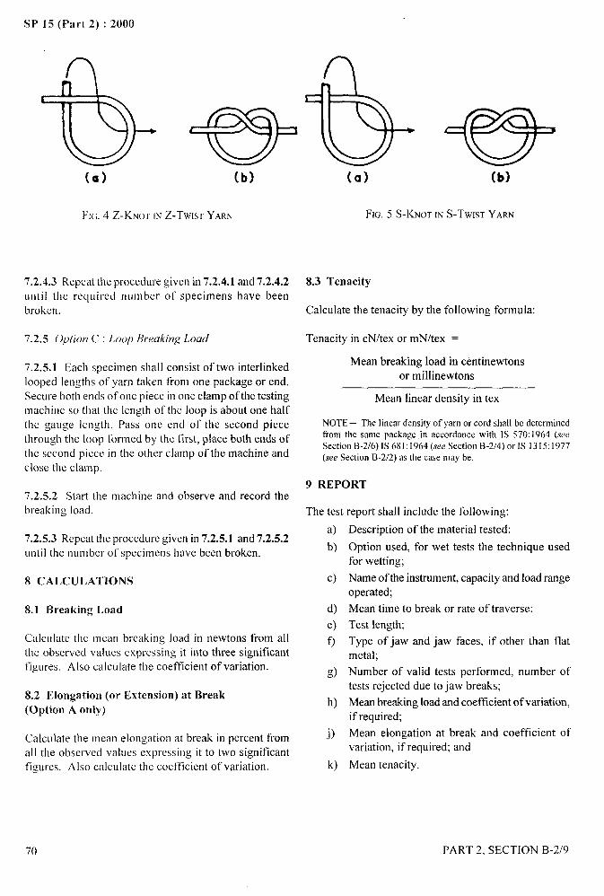
SP 15 (Part 2) :2000
n n —.
(a)
e(b)
FIG. 4 Z-KNOT INZ-TWIST YARN
7.2.4.3 Repeat the procedure given in 7.2.4.1 and 7.2.4.2until the required number of specimens have beenbroken.
7.2.5 option C : Loop Breaking Load
7.2.5.1 Each specimen shall consist of two irtterlinkedlooped lengths of yarn taken from one package or end.Secure both ends of one piece in one clamp oftbe testingmachine so that the length of the loop is about one halfthe gauge length. Pass one end of the second piecethrough the loop formed by the first, place both ends ofthe second piece in the other clamp of the machine andclose the clamp.
7.2.5.2 Start the machine and observe and record thebreaking load.
7.2.5.3 Repeat the procedure given in 7.2.5.1 and 7.2.5.2until the number of specimens have been broken.
8 CALCULATIONS
S.1 Breaking Load
Calculate the mean breaking load in newtons from allthe observed values expressing it into three significantfigures. A Iso calculate the coefficient of variation.
8.2 Elongation (or Extension) at Break(Option A only)
Calculate the mean elongation at break in percent fromall the observed values expressing it to two significantfigures. Also calculate the coefficient of variation.
(a) (b)
FIG. 5 S-KNOT IN S-TWIST YARN
8.3 Tenacity
Calculate the tenacity by the following formula:
Tenacity in cN/tex or mN/tex =
Mean breaking load in centinewtonsor millinewtons
Mean linear density in tex
NOTE — The linear density of yarn or cord shall be determinedfrom the same package in accordance with IS 570:1964 (seeSection 9-2/6) IS681: 1964 (see Section 9-2/4) or IS 1315:1977(see Section 9-2/2) m the case may be,
9 REPORT
The test report shall include the following:
a)
b)
c)
d)
e)
f)
g)
h)
j)
k)
Description of the material tested:
Option used, for wet tests the technique usedfor wetting;
Name of the instrument, capacity and load rangeoperated;
Mean’ time to break or rate of traverse:
Test length;
Type of jaw and jaw faces, if other than flatmetal;
Number of valid tests performed, number oftests rejected due to jaw breaks;
Mean breaking load and coefficient of variation,if required;
Mean elongation at break and coefficient ofvariation, if required; and
Mean tenacity.
.-.t}
).”,
70 PART 2, SECTION B-2/9
I
SP 15 (Part 2) :2000
DETERMINATION OF DRY AND WET TENACITY
AND ELONGATION OF MAN–MADE FIBRES
CONTINUOUS FILAMENT FLAT YARNS
[Source: IS 7703 (Part 2) : 1990]
1 SCOPE
[t prescribes methods for determination of dry andwet tenacity and elongation of man–made fibrescontinuous filament flat yarns.
2 PRINCIPLE
Conditioned specimen or the wet specimen is
gripped between the two clamps of the tensile
testing machine and a continual increasing load
is applied longitudinally by moving one of the
clamps until the specimen breaks. Values of
elongation corresponding to a predetermined load,
maximum breaking strength and elongation at
break of the test specimen are noted. Tenacity is
calculated by dividing the breaking strength innewton by the linear density in tex and multiplying
by 100 and the elongation (percent) by dividing
the elongation by the gauge length.
3 SAMPLING
3.1 Sample shall be so drawn as to be representativeof the lot.
3.2 Sample drawn in accordance with the procedurelaid down in the material specification or as agreedto between the buyer and the seller shall be takenas representative ot’the lot.
4 ATMOSPHERIC CONDITIONS FOR
CONDITIONING AND TESTING OF SPECIMENS
4.1 Unless otherwise agreed to between the buyerand the seller t’or testing of conditioned testspecimens, the test sample shall be conditioned
to a moisture equilibrium from the dry side in thestandard atmosphere (.~ec 1S 6359:1971 given inSection B-111) at 65 * 2 percent relative humidityand 27 + 2°C temperature for determination of drytenacity and elongation.
N()’1[--–\Ybw a Icit smplc under zero knsioa has km kft in
such a M :1} m to mpow. as far as possible all portions ofit to tbcstandard atmospbcrc for 24 brews.tbc test sample shall bc dcenml
10 have reacbcd a state c)F moisture eqailihriam.
PART 2. SECTION B-XI 0
4.2 The test shall be carried out in the standardatmosphere (see 4.1).
4.3 For determination of wet tenacity and elongationthe sample need not be conditioned in the standardatmosphere.
5 APPARATUS
5.1 Testing Machine
A single strand tensile strength testing machine workingon one of the following principles shall be used:
a) Constant–rate–of–traverse (CRT),b) Constant–rate–of–load (CRL), orc) Constant–rate–of+ xtension (CRE).
The specimens shall break within 20’+ 3 secondsin case of constant-rate-of load and constant-rate-of extension machines. In case of constant rate-of-traverse machine the rate-of-traverse shall be300+ 15 mm/minute, and the load range of themachine shall be such that the observed values
would be between 10 and 90 percent of the fullscale load. The permissible error in the, machineat any point in this range shall not exceed + 1percent. The machines shall be provided with thefollowing arrangements:
a) Two clamps to grip the specimen, each providedwith following provisions:i)
ii)
Each clamp of the machine shall be of curvedtype in which the yarn is gripped betweenthe plain-faced jaws and this makes an halfturn round a cylindrical extension of one ofthejaws before passing on to the other similarclamp. The cylindrical friction surface shallbe between 10 to 20 mm in diameter. Anoutline of the above type of clamp is shownin Fig. 1. The length of specimen betweenpoints A and A’ is the test length.Each clamps shall be provided with amechanical or pneumatic device soconstructed that through its means aspecimen can be secured firmly betweenthe jaws of the clamps so that it doesnot slip during the test. Also the edgeof the surface of each jaw shall be such
71
I
/
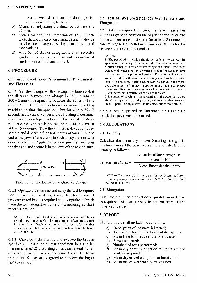
SP 15 (Part 2) :2000
test it would not cut or damage thespecimen during testing.
b) Means for adjusting the distance between theclamps.
c) Means for applying pretension of 0.5* 0.1 cN/tex to the specimen when clamped (tension devicemay be a dead weight, a spring or an air-acturatedmechanism),
d) A scale and dial or autographic chart recordergraduated so as to give load and elongation atpredetermined load and at break.
6 PROCEDURE
6.1 Test on Contlitioncd Specimens for Dry Tenacityand Elongation
6.1.1 Set the clamps of the testing machine so thatthe distance between the clamps is 250 + 2 mm or500 + 2 mm or as agreed to between the buyer and theseller. With the help of preliminary specimens, set themachine so that the specimen breaks within 20 * 2seconds in the case of constant rate of loading or constant-rate-of-extension type machine. In the case of constant-rate-traverse type machine, set the rate of traverse at300 + 15 mm/min. Take the yarn from the conditionedsample and discard a first few metres of yarn. Fix oneend in the jaws of one clamp in such a way that the twistdoes not change. Apply the required pre –tension fromthe free end and secure it in the jaws of the other clalmp.
FIci. ] SCI IEMATICDIAGRAM OF GRIPPINGCLAhnJs
6.1.2 Operate the machine and carry the test to ruptureand record the breaking strength, elongation atpredetermined load as required and elongation at breakfrolm the load elongation curve of the autographic chartrecorder provided.
NOTE — EVCOit’ a test valL]eis isolated on accoont of’a breakocar the jaw. the wdoc shall bc ootcd bat not tiken into accoontin calcolatit~os, !f\och breaks exceecd I(1percent of’thenomberof specimens tested. saitable corrective action shoald be takenon the machine,
6.1.3 Open both the clamps and remove the brokenspecimen. ‘Test another test specimen in a similarmanner as in 6.1.2 discarding at random several metresof yarn betweenminimum 10 testsand the seller.
72
two successive tests.or as agreed to between
Performthe buyer
6.2 Test on Wet Specimens for Wet Tenacity and
Elongation
6.2.1 Take the required number of test specimens either20 or as agreed to between the buyer and the seller andimmerse them in distilled water for at least 2 minutes incase of regenerated cellulose rayon and 10 tninutes foracetate rayon (see Notes I and 2).
NOTES1 The period of’immersion shoold be solficient to wet oat thespecimens thoroughly. I,ooger periods of immersion woold notregister further loss ot’strength if\vettiog is sot~lcien[. Specimenstreated with water-repellent or water-resistant finishes may haveto be immersed for prolonged period. For yarns which do not
wet oLIt readily with water. a penetrating agent such as neutralsoap of a non–ionic wetting agent may be added to the waterbath, the amount of the agent osed being sLIch as not to exceed
that required to obtiainmaximmn rate of wetting oat and as not toatTectdle normal physical properties of the yarn.2 Ifmnrtber of specimens cling together in the water bath, theyshoold be separated by gently raising and lowering them in waterso m to permit a single strand to be drawn oat without strain.
6.2.2 Repeat the procedures laid down in 6.1.1 to 6.1.3for all the specimens to be tested.
7 CALCULATIONS
7.1 Tenacity
Calculate the mean dry or wet breaking strength innewtons from all the observed values and calculate thetenacity as follows:
Mean breaking strength in
Tenacikv in cN/tex =newton ~ 100
.Mean linear density in tex
NOTE — The linear density of’yam shall be determined tyomthe same package in accordance w,itb 1S 7703 (Part 1) : 1990(see Section t3-2/5).
7.2 Elongation
Calculate the mean elongation at predetermined loadas required and also at break in percent from all theobserved values.
8 REPORT
The test report shall include the following;
a)b)c)d)e)
f)
g)h)
Description of the material tested;Type of the testing tnachine and its capacity:Mean time for break or rate-of-traverse:Specimen length:Number of tests performed;Mean dry or wet elongation at predeterminedload, as required;Mean dry or wet elongation at break; andMean dry or wet tenacity as required.
PART 2, SECTION B-2/l O
1
~
I
I
I1;
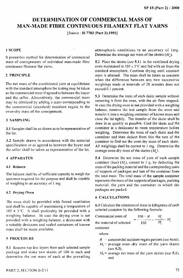
,*—-
SP 15 (Part 2) :2000
DETERMINATION OF COMMERCIAL MASS OF
MAN-MADE FIBRE CONTINUOUS FILAMENT FLAT YARNS
[~ozfrce:IS 7703 (Part 3):1991]
1 SCOPE
It prescribes method for determination of commercialmass of consignments of individual man-made fibre
continuous filament flat yarns.
2 PRINCIPLE
The net mass of the conditioned yarn at equilibriumwith the standard atmosphere for testing may be taken
as the commercial mass if agreed to between the buyer
and the seller. Alternatively. the commercial massmay be obtained by adding a mass corresponding to
the commercial (standard) moisture regain to the
oven-dry mass of the consignment.
3 SAMPLING
3.1 Samples shall be so drawn as to be representative ofthe lot.
3.2 Sample drawn in accordance with the materialspecification or as agreed to between the buyer andthe seller shall be taken as representative of the lot.
4 APPARATUS
4.1 Balance
The balance shall be of sufficient capacity to weigh the
specimen required for the purpose and shall be capable
of weighing to an accuracy of 1 mg.
4.2 Drying Oven
The oven shall be provided with forced ventilationand shall be capable of maintaining a temperature of
105 + 3°C. It shall preferably be provided with aweighing balance. In case the drying oven is notprovided with a weighing balance, a desiccator with
a suitable desiccant and sealed containers of knownmass shall be made available.
5 PROCEDURE
5.1 Remove top few layers from each selected samplepackage and make two skeins of 100 m each and
determine the net mass of each at the prevailing
PART 2. SECTION B-2/l 1
atmospheric conditions to an accuracy of lmg.Determine the average net mass of the skeins (Mn).
5.2 Place the skeins (see 5.1) in the ventilated dryingoven maintained at 105 + 3°C and fed with air from thestandard atmosphere. Continue drying until constantmass is attained. The mass shall be taken as constantwhen the difference between any two successiveweighings made at intervals of 20 minutes does notexceed 0.1 percent.
5.3 Determine the mass of each skein sample withoutremoving it from the oven, with the air flow stopped.In case the drying oven is not provided with a weighing
balance, remove the test sample from the oven andtransfer it into a weighing container of known mass and
close the lid tightly. The transfer of the skein shall bedone in as quickly as possible. Cool the skein and thecontainer in a desiccator to room temperature beforeweighing. Determine the mass of each skein and thecontainer and then deduct from this the tare of thecontainer to find out the oven-dry mass of each skein.All weighings shall be correct to 1 mg. Determine theaverage oven-dry mass of the skeins (A40).
5.4 Determine the net mass of yarn of each samplecontainer (box) (MC), correct to 1 g, by deducting the
mass of the packing material and the corresponding massof supports of packages and tare of the container fromthe total mass. The total mass of the sample containerrepresents the mass of the supports of packages, packing
material, the yarn and the container in which thepackages are packed.
6 CALCULATIONS
6.1 Calculate the commercial mass in kilograms of eachselected container by the following formula:
Commercial mass of 100+R M.— x MC
the material of selected – 100 x M,,
container
where
R = commercial moisture regain percent (see Note),Mo = average oven-dry mass of the yarn skeins
(see 5.3),Mn = average net mass of the yarn skeins (see 5.1),
and
73
_ ..
“9....+,.!
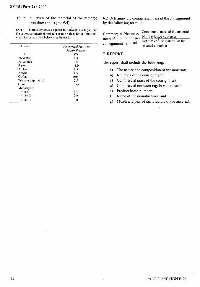
4-
SP 15 (Part 2) :2000
—
M, = net mass of the material of the selectedcontainer (box ) (see 5.4).
N(3TE— Unless otbmvise agreed to between tbe buyer andtile seller, commerical moislore regain values for various man-made tibres as given below may be ased:
(1)Polyester
PolyamideRayonAcetateAcrylicOletinsTriacetate (primary)GlassModacrylic:
C’lasslClass 2
class 3
Cottmerical Moisture
Regui)?Perce17/
(2)0.44.511.06.51.5
zero3.5zero
0.42.0
3.0
6.2 Determine the commercial mass of the consignmentby the following formula:
Commercial mass of the materialCommercial Net mass Ofthe ~elected containermass of = OfcOnsi-x ‘
Net mass of the material of theconsignment Wrneilt
selected container
7 REPORT
The report shall include the following:
a)
b)
c)
d)
e)
9
/3)
The nature and composition of the material;
Net mass of the consignment:
Commercial mass of the consignment;
Commercial moisture regain value used;
Product batch number;
Name of the manufacturer; and
Month and year of manufacture of the material.
74
/
PART 2. SECTION B-2/l 1
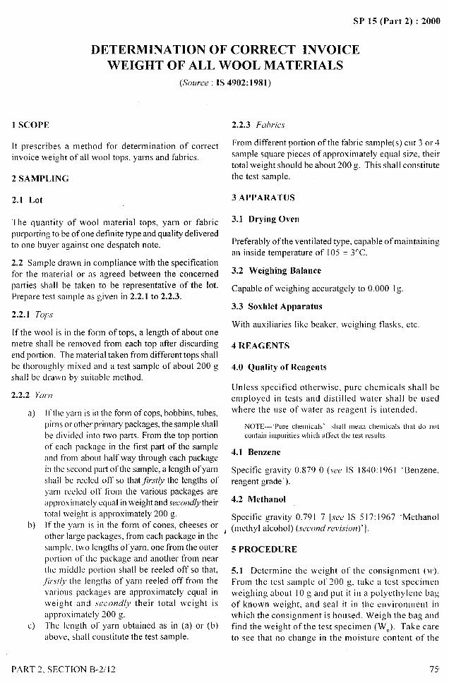
SP 15 (Pal-t 2) :2000
DETERMINATION OF CORRECT INVOICE
WEIGHT OF ALL WOOL MATERIALS
(,%urce : 1S 4902: 1981)
1 SCOPE
It prescribes a method for determination of correct
invoice weight of all wool tops, yarns and fabrics.
2 SAMPLING
2.1 Lot
The quantity of wool material tops, yarn or fabric
purporting to be of one definite type and quality deliveredto one buyer against one despatch note,
2.2 Sample drawn in compliance with the specificationfor the material or as agreed between the concerned
parties shall be taken to be representative of the lot.Prepare test sample as given in 2.2.1 to 2.2.3.
2.2.1 Tops
If the wool is in the form of tops, a length of about onemetre shall be removed from each top after discarding
end portion. The material taken from different tops shallbe thoroughly mixed and a test sample of about 200 gshall be drawn by suitable method.
2.2.2 y~,.,~
a)
b)
c)
II_tbeyarn is in the form of cops, bobbins, tubes,pirns or other primary packages, the sample shall
be divided into two parts. From the top portion
of each package in the first part of the sampleand from about half way through each packagein the second part of the sample, a length of yarn
shal I be reeled off so that jkwy the lengths ofyarn reeled off fi-om the various packages are
approximately equal in weight and seccvdy theirtotal weight is approximately 200 g,.[f tbe yarn is in the form of cones, cheeses or
other large packages, from each package in thesample, two lengths of yarn, one from the outerportion of the package and another from nearthe middle portion shall be reeled off so that,/~rst/J the lengths of yarn reeled off from thevarious packages are approximately equal in
weight and seconc~/.y their total weight is
approximately 200 g.
The length of yarn obtained as in (a) or (b)above, shal I constitute the test sample.
PART 2, SECTION B-2/12
I
2.2.3 Fa[~ric,v
From different portion of the fabric sample(s) cut 3 or 4
sample square pieces of approximately equal size. theirtotal weight should be about 200 g,. This shall constitutethe test sample.
3 APPARATUS
3.1 Drying Oven
Preferably of the ventilated type, capable of maintaining:an inside temperature of 105 * 3“C.
3.2 Weighing Balance
Capable of weighing accurately to 0.000 Ig,.
3.3 Soxhlet Apparatus
With auxiliaries like beaker,
4 REAGENTS
4.0 Quality of Reagents
weighing flasks, etc.
Unless specified otherwise, pure chemicals shall beemployed in tests and distilled water shall be usedwhere the use of water as reagent is intended.
NOTE—’Pure chemicals’ shall mm chemicals that do not
contain impurities which affect the test results.
4.1 Benzene
Specific gravity 0.8790 (sew 1S 1840:1961 ‘Benzene,reagent grade’ ).
4.2 Methanol
Specific gravity 0.791 7 [see 1S 517:1967 ‘Methanol(methyl alcohol) (,wcond revision)’].
5 PROCED(JRE
5.1 Determine the weight of the consignment (w).From the test sample of 200 g, take a test specimenweighing about 10 g and put it in a polyethylene bagof known weight, and seal it in the environment inwhich the consignment is housed. Weigh the bag andfind the weight of the test specimen (Wg). Take careto see that no change in the moisture content of the
75’
_.-y-.
\\,.,’ .
/

SP 15 (Part 2) :2000
test specimen takes placeweighing of the sample.
during the drawing and
5.2 Take the test specimen and wrap it in a filterpaper. Extract the specimen with the 300 ml ofbenzene methanol mixture [3 :2 (v/v)] in a soxhlet
apparatus for three hours, siphoning the solvent ata minimum rate of 6 extractions per hour. Relmovethe test specimen and dry it to constant weight inan oven at a temperature of 105 + 3“C. Determinethe weight of the dried extracted specimen (W.).
5.3 Repeat the test with one more test specimen.
6 CALCULATION
6.1 Calculate the correct invoice weight of the
consignment by the following formula:
W. IOO+RWe’wx —
w’&! 100
76
where
WC = correct invoice weight of the consignment,W = original weight of the consignment,W. = oven dry weight of the deoiled specimen,
W, = original weight of the specimen, andR = commercial moisture regain value (see Note).
NOTE— For the commercial moisture regain values referenceto IS 7033:1973 ‘Commercial moisture regain valoes for t\ooland its products’ shall be made.
6.1.1 Calculate the correct invoice weight of theconsignment by using the formula given in 6.1.
6.2 Calculate the average of the two values obtained asin 6.1 and 6.1.1, if the difference between the two is notmore than 0.5 percent.
7 REPORT
The report shall include the following information:a) Type of material;b) Invoice weight of the consignment;c) Commercial moisture regain values used; andd) Correct invoice weight of the consignment.
-—
—
PART 2, SECTION B-2/12 ~.
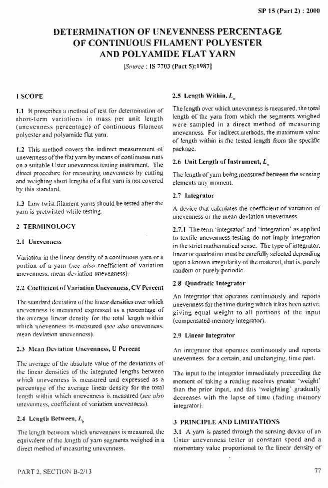
SP 15 (Part 2) :2000
DETERMINATION OF UNEVENNESS PERCENTAGE -4
OF CONTINUOUS FILAMENT POLYESTER
AND POLYAMIDE FLAT YARN-’f.!;...,.-
[Source : 1S 7703 (Part 5): 1987]
1 SCOPE
1.1 [t prescribes a method of test for determination ofshort-term variations in mass per unit length(unevenness percentage) of continuous filamentpolyester and polyamide flat yarn.
1.2 This method covers the indirect measurement ofunevenness of the flat yarn by means of continuous runson a suitable Uster unevenness testing instrument. Thedirect procedure for measuring unevenness by cuttingand weighing short lengths of a flat yarn is not coveredby this standard.
1.3 Low twist filament yarns should be tested after theyarn is pretwisted while testing.
2 TERMINOLOGY
2.1 Unevenness
Variation in the linear density of a continuous yarn or a
portion of a yarn (see a/so coefficient of variation
unevenness, mean deviation unevenness).
2.2 Coefficient of Variation Unevenness, CV Percent
The standard deviation of the linear densities over which
unevenness is measured expressed as a percentage of
the average linear density for the total length within
which unevenness is measured (see u/w unevenness,
mean deviation unevenness).
2.3 Mean Deviation Unevenness, U Percent
The average of the absolute value of the deviations of
the linear densities of the integrated lengths between
which unevenness is measured and expressed as apercentage of the average linear density for the total
length within which linevenness is measured (see u/sounevenness, coefficient of variation unevenness).
2.4 Length Between, Lb
The length between which unevenness is measured, the
equivalent of the length of yam segments weighed in a
direct method of measuring unevenness.
2.5 Length Within, L,,
The length over which unevenness is measured, the totallength of the yarn from which the segments weighedwere sampled in a direct method of measuring
unevenness. For indirect methods, the maximum value
of length within is the tested length from the specificpackage.
2.6 Unit Length of Instrument, L,,
The length of yarn being measured between the sensing
elements any moment.
2.7 Integrator
A device that calculates the coefficient of variatiori ofunevenness or the mean deviation unevenness.
2.7.1 The term ‘integrator’ and ‘integ,rat ion’ as applied
to textile unevenness testing do not imply integration
in the strict mathematical sense. The type of integrator.
linear or quadration must be carefully selected depending
LIpon a known irregularity of the material, that is, purelyrandom or purely periodic.
2.8 Quadratic Integrator
An integrator that operates continuously and reports
unevenness for the time during which it has been active,giving equal weight to all portions of the input
(compensated-memory integrator).
2.9 Linear Integrator
An integrator that operates continuously and reports
unevenness for a certain, and unchanging, time past.
The input to the integrator immediately preceding the
moment of taking a reading receives greater ‘weight’
than the prior input. and this ‘weighting’ gradually
decreases with the lapse of time (fading memoryintegrator).
3 PRINCIPLE AND LIMITATIONS
3.1 A yarn is passed through the sensing device of an
Uster unevenness tester at constant speed and amomentary value proportional to the linear density of
PART 2. SECT1ON B-2/13 77
SP 15 (rat-t 2) :2000
the yarn is recorded. The Uster instruments are equipped
with an integrator that calculates the unevenness
automatically and the value is read while the yarn is
passing through the instrument after 400 m of yarn have
been tested.
3.1.1 Tbe variation of one specific property, linear
density. is termed unevenness. The method is concerned
with measuring the unevenness of flat yarn.
3.1.2 Unevenness is always expressed as betweensuccessive lengths and over a total length. When the
length between which unevenness is measured (Q isvery short 8 mm of yarn ), then reference is often madeto short-term unevenness.
3.1.3 Unevenness can be measured by direct method orindirect methods. The direct method consists of cuttingand weighing yarn segment of length Lb and is thereference method of determining unevenness.Unevenness testing installments. as covered in thisstandard. use the indirect method where unevenness isdetermined by the measurement of yarn propertiesclosely related to and dependent on linear density. Theaccuracy of the indirect method and of an instrumentutiiizing it can be judged by a comparison of the value
of unevenness it gives with one obtained by the directmethod of cutting and weighing.
3.1.4 The LJster unevenness testing instrumentsmeasure those properties of the yarn which change thecapacitance when the yarn passes between the platesof a capacitor.
3.1.5 A number of mathematical concepts are used toexpress the unevenness of yarn. They are all based onthe coefficient of variation or its square. There is,therefore. some advantage in using an unevenness testinginstrument that gives the coefficient of variation and thereby fits into the general mathematical scheme.
4 APPARATUS
4.1 Capacitance-Type Unevenness TestingInstrument
A Suitable Uster unevenness tester using automaticintegrator or any other suitable instrument which can
satisfy the requirements. The instrument shall have thefollowing accessories provided.
4.1 ~1 Package Holders, Guides, Tension Devices und
Take-zip ~lcchut~ism
Which allow for or assist in. uniform delivery of the yarn
at the specified speed without undue acceleration ordeceleration and at a reasonably constant tension.
4.1.2 Uecorder
TO give a permanent chart record of the test details and
to depict the unevenness. It is a means to record allunevenness.
4.2 Pretwisting with constant tension material feedingfacilities for low-twist filament yarns to impart false-twist into low-twist filament yarn while it passes betweenthe sensing elements at a uniform tension.
5 ATMOSPHERIC CONDITIONS FORCONDITIONING AND TESTING OF SAMPLE
5.1 The test sample shall be conditioned to a state ofmoisture equilibrium from dry side in standardatmosphere at 65 + 2 percent relative humidity and27 + 2°C temperature (see IS 6359:197 I given in Section
B– 1/ I ) and tested in the same atmosphere.
6
NOTE— Wkm a test sample bas been left in such a way m to
expose as Iar as possible. all portions of it to the standardatmosphere for 24 hours. tbe test sample shall be deemed to havereached a state ofmois(ure cqoilibriuln.
PROCEDURE
6.1 Calibrate the unevenness testing instrument asprescribed by the instrument manufacturer.
NOTE— Do not separate the [eng~bof yarn m be tested from thepackagespriorto testing.
6.2 Mount the package on a suitable holder. Thread
the free end of the yarn through the sensing elements ofthe tester and through the take-up mechanism. If a lowtwist yarn is to be tested, pass it through a deviceimparting false twist.
6.3 Set the take-up mechanism to yarn speed of 100mhnin or to speed of travel as agreed to between thebuyer and the seller. Jf a recorder is used, set the yarnto chart speed 10 cm/min with test time limited to fourminutes.
6.4 Start the take-up mechanism of the tester andrecorder, if used. Adjust the controls of the tester torecord on the central part of the recorder chart or on thecentral part of the insturment meter or both.
6.5 Turn on the integrator. Test a total yarn length ofat least 400 m in one uninterrupted run, unless otherwise
agreed upon by the purchaser and the seller. Record themeter unevenness value.
6.6 Follow the unevenness tester instruction manualfor operational procedures not outlined in this method.
—..-
,-.‘.-
\,,,
,0,.~ .*
PART 2, SECTION B-2/l 3
.-SP 15 (Part 2) :2000
7 CALCULATIONS
7.1 The CV percentage and U percentage can beestimatid from the chart by converting the line of therecord into a frequency distribution. U percentage canalso be estimated by the use of a planimeter. Normally,however, CV percenta:c or U percentage wil I be readfrom dle integrator (,MW6.5).
7.2 If more than one values of CV percentage orU percentage is obtained for individual packages. thencalculate arithmetic mean of values of unevenness foreach package.
7.3 Calculate the average of CV percentage of
U percentage for all packages.
7.4 If required. Clacuiate the coefficient of variation orthe standard deviation (or both) of the CV percentageor U percentage values obtained for each package.
8 REPORT
8.1 State that the specimens were tested as dirccteci inthe standard. Describe the material or product sampled.
8.2 Report the following information
8.2.1 Number of specimens tested.
8.2.2
8.2.3
8.2.4
8.2.5
Instrument used and type of integrator, if used.
Yarn travel speed.
Length of specimen tested. ‘ --j
Chart speed or yarn-to–chart speed ratio andmethod ofchart calculation. if chart is used.
8.2.6 Type ofsettitlg tlsed, tllatis, t}orlnal, illertot"llalfinert.
8.2.7 Atmosphericc onditionsu sed,ifnotstandard.
8.2.8. Average value of unevenness obtained as CVpercentageor U percentage.
8.2.9 Coefficient ofvariation orstandard deviation, orboth, ifcaiculated,
8.2.10. Thevalttes oflen@betweenLll andlengthwithin[.,,).
,Nol’r –- ‘I”lwpretkrred )V:IY 01 \I riting the unevenness is to pllt
[<i, and /.,l wIlucs ill parentheses (l.I,, L,, ) alter CV perwntage or (1perccntmgc.
E.vc/mp/e — CV (8 mm, 100 m) to be read as follows:
‘Coefficient of variation unevenness bet~veen 8 mm
lengths Jvithin 100-m lengths’.
PART 2, SECTION B-XI 3 79
II
I I
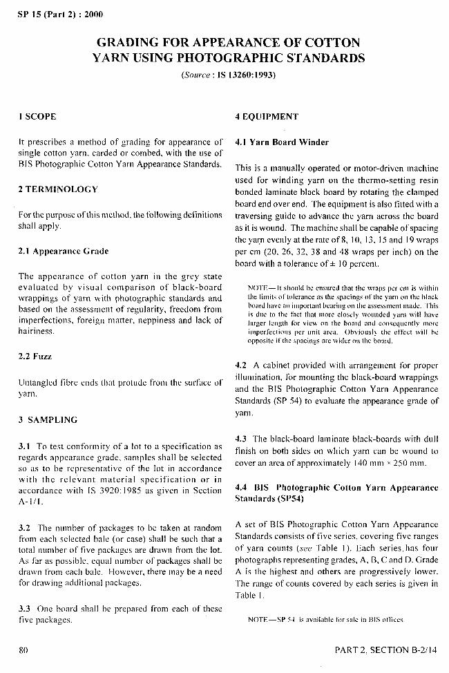
SP 15 (Part 2) :2000
GRADING FOR APPEARANCE OF COTTON
YARN USING PHOTOGRAPHIC STANDARDS
(Source: IS 13260:1993)
1 SCOPE
It prescribes a method of grading for appearance of
single cotton yarn, carded or combed, with the use ofBIS Photographic Cotton Yarn Appearance Standards.
2 TERMINOLOGY
For the purpose of this method, the following definitionsshall apply.
2.1 Appearance Grade
The appearance of cotton yarn in the grey stateevaluated by visual comparison of black-boardwrappings of yarn with photographic standards andbased on the assessment of regularity, freedom fromimperfections, foreign matter, neppiness and lack ofhairiness.
2.2 Fuzz
Untangled fibre ends that protude from the surface ofyarn.
3 SAMPLING
3.1 To test confornlity of a lot to a specification asregards appearance grade. samples shall be selectedso as to be representative of the lot in accordancewith the relevant material specification or in
accordance with IS 3920:1985 as given in SectionA-III.
3.2 The number of packages to be taken at randomfrom each selected bale (or case) shall be such that atotal number of five packages are drawn from the lot.As far as possible, equal number of packages shall bedrawn from each bale. However, there may be a needfor drawing additional pack:iges.
3.3 One board shall be prepared from each of thesefive packages.
80
4 EQUIPMENT
4.1 Yarn Board Winder
This is a manually operated or motor-driven machine
used for winding yarn on the thermo-setting resin
bonded laminate black board by rotating the clamped
board end over end. The equipment is also fitted with a
traversing guide to advance the yarn across the board
as it is wound. The machine shall be capable of spacing
the ya~n evenly at the rate of 8, 10, 13, 15 and 19 wraps
per cm (20, 26, 32, 38 and 48 wraps per inch) on the
board with a tolerance of + 10 percent.
NOT~- It shoLIld be ensomi that the \vraps per cm is \\,ithintbc limits of tolerance as the spacings ot’the yarn on the blackboard have an important bearing on tbe assessment made. This
is doe to [he t’act that more closely \voondcd yarn will havelarger lcngtb for view on the board and consequently moreimperfections per onit area. Obvioosly tbe utl’cct will beopposite iI the spacin:s are wider crnthe board,
4.2 A cabinet provided with arrangement for proper I ,.. .
illumination, for mounting the black-board wrappings -)
and the BIS Photographic Cotton Yarn Appearance
Standards (SP 54) to evaluate the appearance grade ofii+/.+
yarn.
4.3 The black-board laminate black-boards with dull
finish on both sides on which yarn can be wound to
cover an area of approximately 140 mm x 250 mm.
4.4 111S Photographic Cotton Yarn AppearanceStandards (SP54)
A set of BIS Photographic Cotton Yarn Appearance
Standards consists of five series, covering five ranges
of yarn counts (see Table 1). Each series. has four
photographs representing grades, A, B, C and D. Grade
A is the highest and others are progressively lower.
The range of counts covered by each series is given in
Table 1.
NOTE— SP 54 is available ti)r sale in t31Sotlices
PART 2, SECTION B-2/14
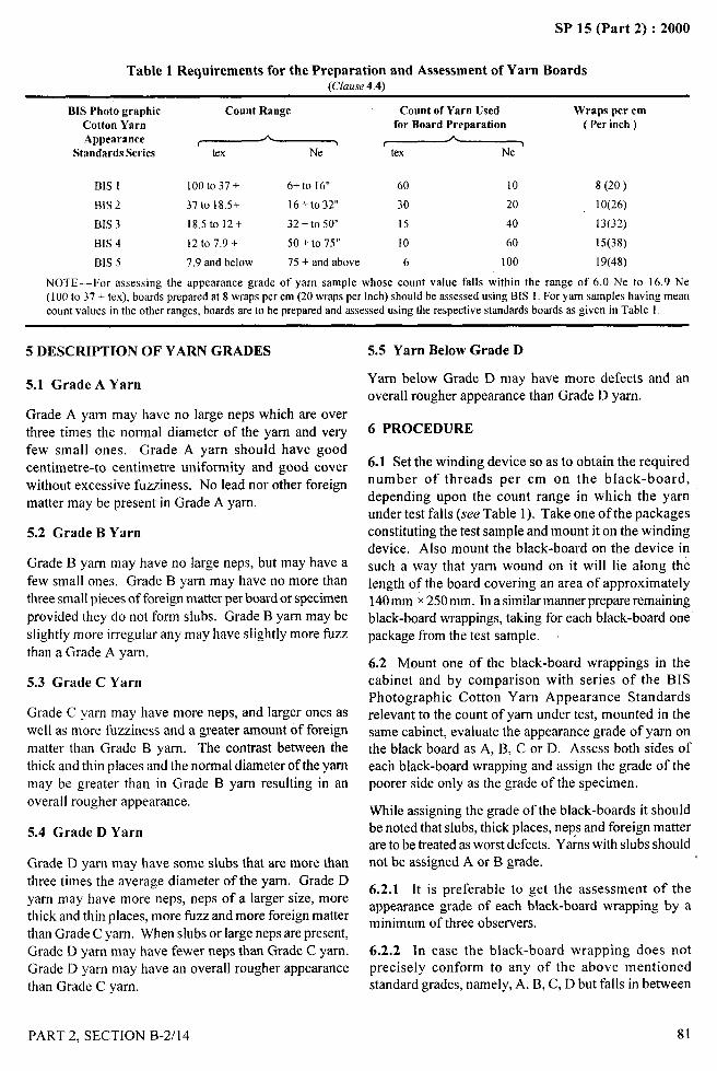
SP 15 (Part 2) :2000
Table 1 Requirements for the Preparation and Assessment of Yarn Boards(Clause4.4)
BIS Photo graphic Count Range Count of Yarn Used Wraps per cmCotton Yarn for Board Preparation ( Per inch)
Appearance ~ ~Standards Series tex
BIS 1 looto 37+ 6+ to 16” 60 10 8 (20)
BIS 2 37to 18.5+ 16+ to 32” 30 20 10(26)
BIS 3 18.5 to 12+ 32+ to 50” 15 40 13(32)
BIS 4 12t07.9+ 50+ to 75” 10 60 15(38)
BIS 5 7.9 and below 75 + and above 6 I00 19(48)
NOTE —For assessing the appearance grade of yarn sample whose count value falls within the range of 6.0 Ne to 16.9 Ne(100 to 37 + tex), boards prepared at 8 wraps per cm (20 wraps per Inch) should be assessed using BIS 1. Foryarn sampleshavingmeancountvalues in the other ranges, boards are to be prepared and assessed using the respective standards boards as given in Table 1.
5 DESCRIPTION OF YARN GRADES
5.1 Grade A Yarn
Grade A yarn may have no large neps which are over
three times the normal diameter of the yarn and veryfew small ones. Grade A yarn should have good
centimetre-to centimetre uniformity and good coverwithout excessive fuzziness. No lead nor other foreignmatter may be present in Grade A yarn.
5.2 Grade B Yarn
Grade B yarn may have no large neps, but may have a
few small ones. Grade B yarn may have no more than
three small pieces of foreign matter per board or specimen
provided they do not form slubs. Grade B yarn maybe
slightly more irregular any may have slightly more fuzz
than a Grade A yam.
5.3 Grade C Yarn
Grade C yarn may have more neps, and larger ones aswell as more fuzziness and a greater amount of foreign
matter than Grade B yam. The contrast between the
thick and thin places and the normal diameter of the yarnmay be greater than in Grade B yam resulting in an
overall rougher appearance.
5.4 Grade D Yarn
Grade D yam may have some slubs that are more than
three times the average diameter of the yam. Grade Dyam may have more neps, neps of a larger size, morethick and thin places, more fuzz and more foreign matterthan Grade C yam. When slubs or large neps are present,
Grade D yam may have fewer neps than Grade C yam.Grade D yarn may have an overall rougher appearancethan Grade C yam.
‘-”--
5.5 Yarn Below Grade D
Yam below Grade D may have more defects and anoverall rougher appearance than Grade D yam.
6 PROCEDURE
6.1 Set the winding device so as to obtain the requirednumber of threads per cm on the black-board,depending upon the count range in which the yarnunder test falls (see Table 1). Take one of the packagesconstituting the test sample and mount it on the windingdevice. Also mount the black-board on the device insuch a way that yarn wound on it will lie along thelength of the board covering an area of approximately140rnm x250 mm. In a similar manner prepare remainingblack-board wrappings, taking for each black-board onepackage from the test sample. i
6.2 Mount one of the black-board wrappings in thecabinet and by comparison with series of the BISPhotographic Cotton Yarn Appearance Standardsrelevant to the count of yam under test, mounted in thesame cabinet, evaluate the appearance grade of yam onthe black board as A, B, C or D. Assess both sides ofeach black-board wrapping and assign the grade of thepoorer side only as the grade of the specimen.
While assigning the grade of the black-boards it shouldbe noted that slubs, thick places, neps and foreign matterare to be treated as worst defects. Yams with slubs shouldnot be assigned A or B grade.
6.2.1 It is preferable to get the assessment of theappearance grade of each black-board wrapping by aminimum of three observers.
6.2.2 h case the black-board wrapping does notprecisely conform to any of the above mentioned
II
standard grades, namely, A, B, C, D but falls in between
PART 2, SECTION B-2/l 4 81

SP 15 (Part 2) :2000
two consecutive grades, denote the appearance gradeof the yarn by ‘+’ mark after the letter designating thelower of the two grades.
6.2.3 In case the black-board wrapping appears poorerthan Grade D, denote the appearance grade of the yam
as ‘<D’ (Below D).
6.3 Following the procedure given in 6.2, evaluate the
appearance grade of the remaining black-board
wrappings.
6.4 If the observers differ by morethanonegrade,fivemorepackagesmaybedrawnandevaluated.
7 CALCULATION
7.1 In acceptance testing, if no specimen falls more thatone grade below that specified, determine the percentageof specimens that are equal to or better than the specifiedgrade. If 80 percent of the specimens graded are equalto or better than the specified grade, and remaining 20percent do not fall below the next lower grade considerthe lot as passing yam appearance specification. If oneor more specimens fall more than one grade below thatspecified, reject the lot.
7.2 For research and experimental purposes, convertthe yam appearance grade of all the five grades of eachof the graders to their respective appearance index values
. —
using Table 2 and calculate the individual grader’s —..average index. From the average index values of all the
. .
graders, calculate the average index value of the yarn
sample, correct to an integer.
,4
~., “..
Table 2 Conversion of Grade into Appearance Index !;~
Grade AppearanceIndex
(1) (2)
A and above 130B+ 120B 110c+ 100c 90D+ 80D
-,70
Below D 60
8 REPORTS
The test report shall include the following:
a)
b)
c)
d)
e)
Count of yam as indicated on the package;
Number of black-board wrappings examined;
Average appearance index and appearancegrade of the yarn in the lot;
Range of grades; and
Series number of the BIS PhotographicApearance Standards used for grading thesample.
.- -.
/
82
,1
PART 2, SECTION B-2/14 II
SP 15 (Part 2) :2000
DETERMINATION OF LENGTH AND
WIDTH OF WOVEN FABRICS(Source: IS 1954:1990)
1 SCOPE
1.1 It prescribes two methods for determination of lengthand width of pieces (of any length) of all kinds of wovenfabrics that are in the state of relaxation obtained byexposure (free from applied tension) to the standardatmosphere.
1.2 The methods are applicable to woven fabrics(including ‘stretch’ fabrics) made up full width of foldeddown the middle.
2 TERMINOLOGY
2.1 Length of Piece
The distance between the outermost complete wefi threadin a piece, other than weft threads of other materials atthe end(s) of the piece.
2.2 Width of Piece
2.2.1 Overall Width
The distance, at right angles to the length of the fabric,between the outermost warp thread in a piece.
2.2.2 Width Between Lists or Selvedges (Usable Width)
The distance at right angles to the length of the fabric,
between the outermost warp thread of the body of thefabric.
3 APPARATUS
3.1 Calibrated Steel Rule of length at least 2 m(preferably 3 m), and graduated in centimetres andmillimetres.
3.2 Table having a smooth flat surface, of width greaterthan that of the fabric when prepared for measuring,and of length at least 4 m.
NOTE — If a table of substantially greater length is used, thedistance between temporary marks (see 6.2.1 and 6.2.3) may alsobe increased,
4 ATMOSPHERIC CONDITIONS FORCONDITIONING AND TESTING
4.1 The fabric pieces shall be conditioned to moistureequilibriLlm in the standard atmosphere of 65 + 2 percent
relative humidity and 27* 2°C temperature from the dryside (see also IS 6359:1971 given in Section B–l/l).
NOTE—The strain imposed during manufacturing and tinishingmay appreciably affect the length and width of fabrics, and somerecovery may take place during storage. It is, therefore, advisablefor fabrics to remain unrolled and freely exposed for as long aspossible in order to allow for relaxation before takingmeasurements. Fabrics containing threads of rubber may requirea period not less than foor days for relaxation.
4.2 The testing of fabric pieces shall be carried out inthe standard atmosphere (see 4.1) or prevailingatmosphere depending upon the method used.
5 SAMPLING
Sample from the lot shall be drawn so as to berepresentative of the lot. Sample drawn in accordancewith the relevant material specification or as agreed to
between the buyer and the seller shall be representativeof the lot.
6 DETERMINATION OF LENGTH
6.1 Location of Marks and Measurements
6.1.1 Fabric Made up Full Width
Measure and mark the fabric along two lines, each \positioned at a distance of about one-quarter of the widthof the fabric from the adjacent selvedge.
6.1.2 Fabric Folded Down the Middle
Measure to the nearest millimetre and mark one side ofthe fabric along a line approximately half-way betweenthe selvedge and the fold, then turn the fabric over andmark and measure the other side in a similar manner.
NOTE— Pieces of width less than that of the measuring tablemay be opened and measured as described in 6.1.1.
6.2 Method 1
6.2.1 Preliminary Markings
Place the piece on the table (at full width, folded downthe middle if received in this state) so that the first 3to 4 m portion lies flat and free from applied tension,and make temporary marks (used only to determinecompletion of relaxation and conditioning) 3 m or 2 ,
m apart, near the end of the piece. Then draw the
PART 2, SECTION B-3/l 83
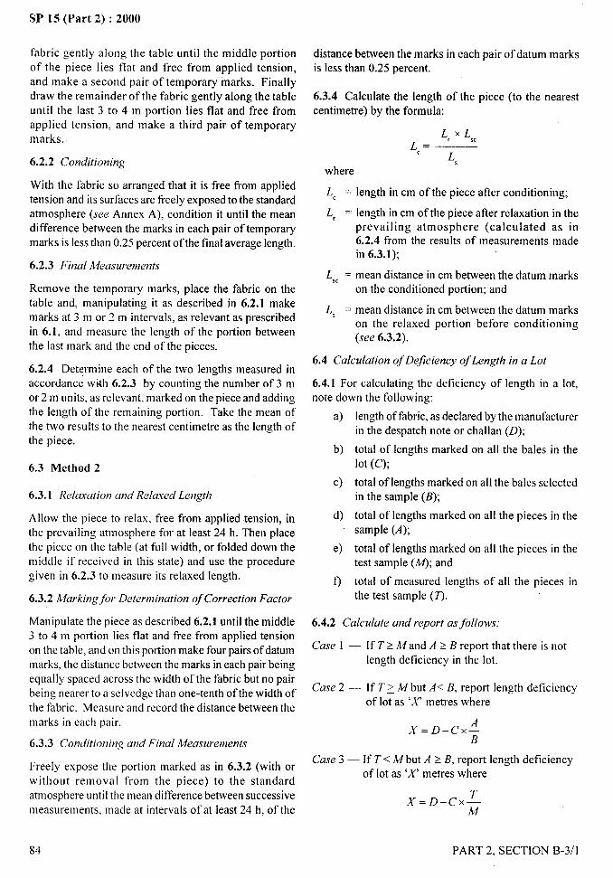
. . ..—SP 15 (Part 2) :2000
fabric gently along the table until the middle portionof the piece lies flat and free from applied tension,and make a second pair of temporary marks. Finallydraw the remainder of the fabric gently along the tableuntil the last 3 to 4 m portion lies flat and free fromapplied tension, and make a third pair of temporarymarks.
6.2.2 Conditioning
With the fabric so arranged that it is free from appliedtension and its surfaces are fi-eely exposed to the standardatmosphere (see Annex A), condition it until the meandifference between the marks in each pair of temporarymarks is less than 0.25 percent of the final average length.
6.2.3 Final Measurements
Remove the temporary marks, place the fabric on thetable and, manipulating it as described in 6.2.1 makemarks at 3 m or 2 m intervals, as relevant as prescribedin 6.1, and measure the length of the portion betweenthe last mark and the end of the pieces.
6.2.4 Determine each of the two lengths measured inaccordance with 6.2.3 by counting the number of 3 mor 2 m units, as relevant, marked on the piece and addingthe length of the remaining portion. Take the mean ofthe two results to the nearest centimetre as the length ofthe piece.
6.3 Method 2
6.3.1 Rela.~ation and Relaxed Length
Allow the piece to relax, free from applied tension, inthe prevailing atmosphere for at least 24 h. Then placethe piece on the table (at full width, or folded down themiddle if received in this state) and use the proceduregiven in 6.2.3 to measure its relaxed length.
6.3.2 Marking for Determination of Correction Factor
Manipulate the piece as described 6.2.1 until the middle3 to 4 m portion lies flat and free from applied tensionon the table, and on this portion make four pairs of datummarks, the distance between the marks in each pair beingequally spaced across the width of the fabric but no pairbeing nearer to a selvedge than one-tenth of the width ofthe fabric. Measure and record the distance between themarks in each pair.
6.3.3 Conditioning and Final Measurements
Freely expose the portion marked as in 6.3.2 (with orwithout removal from the piece) to the standard
atmosphere until the mean difference between successivemeasurements, made at intervals of at least 24 h, of the
84
distance between the marks in each pair of datum marksis less than 0.25 percent.
6.3.4 Calculate the length of the piece (to the nearestcentimetre) by the formula:
L, X L,,cL,=
L,
where
LC = length in cm of the piece after conditioning;
L, = length in cm of the piece after relaxation in theprevailing atmosphere (calculated as in6.2.4 from the results of measurements madein 6.3.1);
L,, = mean distance in cm between the datum markson the conditioned portion; and
L, = mean distance in cm between the datum markson the relaxed portion before conditioning(see 6.3.2).
6.4 Calculation of Deficiency of Length in a Lot
6.4.1 For calculating the deficiency of length in a lot,note down the following:
a)
b)
c)
d)
e)
0
length of fabric, as declared by the manufacturerin the despatch note or challan (D);
total of lengths marked on all the bales in thelot (c);
total of lengths marked on all the bales selectedin the sample (B);
total of lengths marked on all the pieces in thesample (A);
total of lengths marked on all the pieces in thetest sample (M); and
total of measured lengths of all the pieces inthe test sample (7).
6.4.2 Calculate and report as follows:
Case 1 — If T> Mand A 2 B report that there is notlength deficiency in the lot.
Case 2 — If T? M but A< B, report length deficiencyof lot as ‘X’ metres where
X= D–CX;
Case 3 — If T< M but A 2 B, report length deficiencyof lot as ‘X’ metres where
X= D–CX;
PART 2, SECTION B-3/l
-.
SP 15 (Part 2) :2000
Cc{.ye4 – If T< M and A <B, report length deficiency of
lot as ‘X where.Yis either equal to D – Cx~
Aor equal to D–c’ x — whichever is greater.
B
7 DETERMINATION OF WIDTH
7.1 Measurements
7.1. I Take each measurement to the nearest m illimetreand with the steel rule resting on the fabric in a directionat right angles to the selvedge.
7.1.2 Fabric folded down the middle, if received in thatstate, may be relaxed and conditioned in that state, butall measurements shall be taken from edge to edge withthe fabric open and laid flat.
7.3 Method 1 — For Pieces (Samples) of Length
at least 0.5 m and not Exceeding 5m
With fabric laid flat on the table and free from appliedtension, made at least four marks at equal intervals atpoints close to a seivedcge, the tirst and the last marksbeing made not closer to the adjacent end of the fabricthan one fifth of the length of the sample. Then exposethe sample to the standard atmosphere and condition itas described in 7.2.2 but taking measurements at eachmark. Record the final readings at each point.
7.4 Take the mean of the final measurement made in
accordance with 7.2.3 or 7.3 (as relevant) as the widthoftbe piece.
7.5 Record the Minimum and Maximum Widths
7.6 Method 2
7.2 Method 1 For Pieces of Length (lreater than 5 m 7.6.1 Re/u.YcitIonund Relaxed Widfh
7.2.1 Pre/in~im/y markingPlace the piece on the table (at full width, or foldeddown the middle if received in this state) so that thefirst 1 to 2 m portion lies flat and free from appliedtension, and make a temporary mark (used only todetermine completion of relaxation and conditioning),at a point close to a selvedge and approximately I mfrom the end oftbe piece. Then draw the fabric gentlyalong the table until the middle portion of the piecelies ilat and free from applied tension, and make asecond mark. Finally, draw the remainder of the fabricgellt]Y along the table until the last i to 2 m portion lies
flat and free from applied tension and make a thirdtemporary mark.
7.2.2 Conditioning
With the fabric so arranged as to be free from appliedtension and freely exposed to the standard atmosphere(see Annex A), condition it until the difference betweensuccessive measurements. made at intervals of at least2411, of the appropriate width of the fabric as determ ined
at the three marked measuring points is less than 0.25
percent at each measuring point.
Allow the piece to relax, free from applied tension, inthe prevailing atmosphere for at least 24 hours. Thenplace the piece on the table (at full width) or foldeddown the middle if received in this state and useprocedure given in 7.2.3 to determine its relaxed width.
7.6.2 A4urkitlg fbr Dcterminution qfCorrcctiorr Fuctor
Manipulate the piece as described in 7.6.1 until themiddle 2 to 3 m portion lies flat and free from appliedtension on the table, and on this portion make four marksat points close to a selvedge and at least 25 cm butpreferable 50 cm apart. Measure and record the widthat each oftbe four marks.
7.6.3 Conditioning and Finul A4eo.sllrenwnts
Freely expose the portion marked in accordancewith 7.6.2 (withor without removal from the piece) tothe standard atmosphere until the difference betweensuccessive measurements, made at intervals of at least24 hours, of the width of the tibric is less than 0.25
percent at each of the four measuring points. Recordthe mean of the last four readings.
7.6.4 Calculate the width of the piece by the formula:
Remove the temporary marks place, the fabric on the We= W, x ‘c
table and. manipulating: as described in 7.2.1 measure W,
the width of the fabr-ic at least five times at equal intervals whereof not more than 10 m along the length of the piece, thefirst measurement being made at a position at least 1 m [4’, = width in cm oftbe piece after conditioning:
from one end of the piece and the last measurement at W, = mean width in cm oftbe piece after relaxation
least I m from the other end. (see 7.6.1 );
_ ...-.,
\,
PART 2. SECTION B-3/l 85
/
I
I II
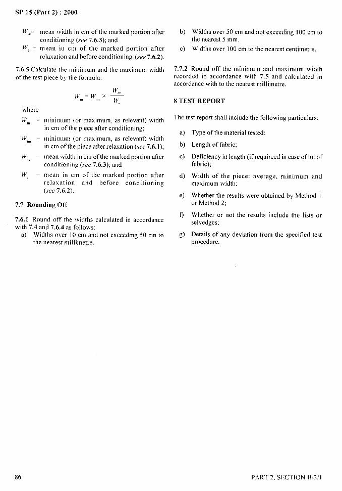
SP 15 (Part 2) :2000
W’,,= mean width in cm of the marked portion after
conditioning (see 7.6.3); and
W’, = mean in cm of the marked portion after
relaxation and before conditioning (see 7.6.2).
7.6.5 Calculate the minimum and the maximum widthof the test
where
Iv,,, =
W,,,l =
W,c =
w, =
piece by the formula:
W,cIV,,,= [{n, x —J/jf,
minimum (or maximum, as relevant) widthin cm of the piece after conditioning;
minimum (or maximum, as relevant) widthin cm of the piece after relaxation (see 7.6.1);
mean width in cm of the marked portion afterconditioning (see 7.6.3); and
mean in cm of the marked portion afterrelaxation and before conditioning(see 7.6.2).
7.7 Rounding Off
7.6.1 Round off the widths calculated in accordancewith 7.4 and 7.6.4 as follows:
a) Widths over 10 cm and not exceeding 50 cm tothe nearest millimetre.
b)
c)
7.7.2
Widths over 50 cm and not exceeding 100 cm tothe nearest 5 mm.
Widths over 100 cm to the nearest centimetre.
Round off the minimum and maximum widthrecorded in accordance with 7.5 and calculated inaccordance with to the nearest m illimetre.
8 TEST REPORT
The test report shall include the following particulars:
a)
b)
c)
d)
e)
9
g)
Type of the material tested;
Length of fabric;
Deficiency in length (if requireed in case of lot offabric);
Width of the piece: average, minimum andmaximum width;
Whether the results were obtained by Method Ior Method 2;
Whether or not the results include the lists orselvedges:
Details of any deviation from the specified testprocedure.
-- -“i.-,
‘1
86 PART 2, SECTION B-3/1
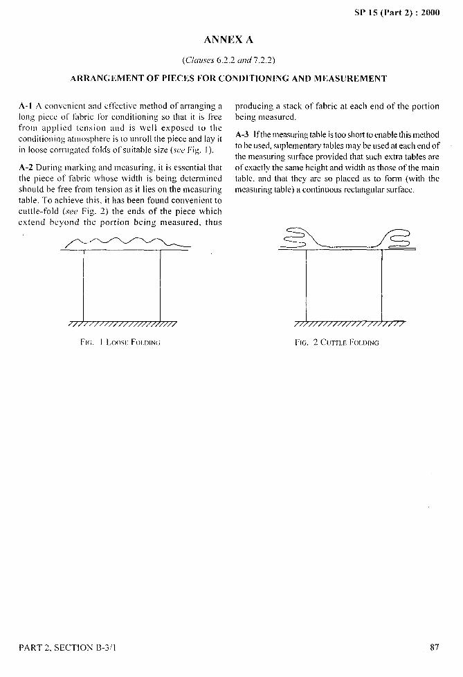
SP 15 (Part 2) :2000
ANNEX A
(Cluvses 6.2.2 amf 7.2.2)
ARRANGEMENT OF PIECES FOR CONDITIONING AND MEASUREMENT .-.....-4!‘$,,
A-1 A convenient and effective tmetbod of w-ranging along piece of fabric for conditioning so that it is freefrom applied tension and is well exposed to the
conditioning atmosphere is to unroll the piece and lay itin loose corrugated folcis ofsuitabie size (SW Fig. I).
A-2 During marking and measLlring, it is essential that
the piece of fabric whose width is being determined
should be free from tension as it lies on the measuring
table. To achieve this, it has been found convenient to
cuttle-fold (see Fig. 2) the ends of the piece which
extend beyond the portion being measured,
/’——~
7/// ///////////////////
FI(;. 1 LOOSE FOLOINW
PART 2, SECTiON B-3/l
thLIS
producing a stack of fabric at each end of the portionbeing measLmed.
A-3 Ifthe measuring table is too short to enable this method
to be used, sLlplelmentary tables maybe Llsed at each end of
the lmeasLa-ing surface provided that such extra tables are
of exactly the same height and width as those of the main
table, and that they w-e so placed as to form (with the
measuring table) a continuoL]s rectangLllar surface.
UFw. 2 C[JTTLE FOLWNG
87
J--JQb
..—
SP 15 (Part 2) :2000
DETERMINATION OF THREADS PER UNIT
LENGTH IN WOVEN FABRICS
(,%w-cc : 1S 1963: 1981)
lute industry is an export o~iented industry and the overseas consumers use the terms ‘porter’ and ‘shots’ forexpressing warp and lveft threads per unit length of jute f’abrics. For the convenience of the overseas consumersconversion factors for converting values of warp threads per decimeter to ‘porter’ and weft threads per decimetreto ‘shots per inch’ have been given in the standard (see Note under 5.3).
Apart from the two methods given in this standard, method based on LISC of different types of line gratings is alsofollowed.
1 SCOPE
1.1 It prescribes ttvrr methods for determination of warpthreads and weft threads per unit length (per centimetreand per decimetrc) in woven fabrics.
1.2 The methods are applicable to all textile fabricsirrespective of their composition (that is. whether theyare made of co~ton, wool, silk. jute. man-made flbres orblends of two or more soch fibres), manufacturingprocesses and finishing treatments.
2 TERMINOLOGY
For the purpose of this test method the following termsshall apply.
2.1 Porter
The value obtained by counting in jute fabric the numberof warp threads per gauge length of 47 mm (or 37/20inch) and dividing it by the number of threads per split(2 for hessian, 3 for single warp twill cloth, 4 for doublewarp plain fabric and 6 for doubie \varp twill cloth).
~ol’1: —“lbIs dcfitlltioll of “porter”based on tile [ndi:mpracliccrclkts to [be finisbcd hbl-ic. md bas 10be distinguisbcd from (IICI)undcc praclicc according lo wbicb ‘porter”is evaluated in termstll’loom reed uscci in ~+coiing lbc clntk
2.2 shot
Single thread of weft yarn in jute fabrics running fromsetvedge to selvedge. It is inserted in one passage of theshuttle across the loom.
3 ATMOSPHERIC CONDITIONS FORCONDITION1NG AND TESTING
3.1 I’rior to test. the fabric shall be conditioned tomoisture equilibrium from dry side, in the standard
8S
atmosphere of 65 + 2 percent relative humidity and27 * 2°C temperature as prescribed in IS 6359:1971
(see Section B- I/1).
3.2 The test shall be carried out in a standard atmosphere(see 3.1).
3.3 The conditioning and testing may also be carried outin prevailing atmosphere, if agreed between the parties.
4 GENERAL INFORMATION
4.1 Choice of Method
Me[hod A (see 5) — Th is method is suitable for fabrics,the individual threads of which can be easily identified
with a thread counting glass.
Mel}mu’ B (see 6) — This method is suitable for fabrics,the individual threads of \vhich cannot be easily identifiedwith a thread counting glass.
~011 —It ma? he noted that IIOIK of’ time metbmls my be
applicable to cer(ain spccid type of Ihbriu. SLICI1 as Moleskin,I,appct. Buttzr,Leno \VIXW3s.etc.
N Deterinination shall not be made (a) within 50 mm
from the selvedges, or (b) within two metres from eitherend of a piece, roll or bolt. In case of fabrics havingwidth from IO cm to 20 cm the selvedge ends shall be
excluded while counting.
NOTI — T’bisis not opplicribk to mrmv fabrics
4.3 Narrow Fabrics
In case of narrow fabrics having width of 10 cmor less, all warp threads including selvedge endsshall be counted and expressed as threads per fullwidth.
PART 2. SECTION B-3/2
, . .1-
),,..
SP 15 (Part 2) :2000
4.4 Design Fabrics b) 20 mm. if the ntlmber of threads are more than
2(I per centimetre (200 per decimetre). but less
For design fabrics, it is convenient (a) to determine the than or equal to I00 per centimetre ( I 000 per
number of units in a weave repeat from a point paper decimetre); and
diagram, and (b) to count(i) the number of whole repeats, c) 10 mm, if the number of threads are more than
and (ii) remaining units, in the distance across which the 100 per centimetre ( 1000 per decimetre).
threads are to be counted; and calculate from the data soobtained, the number of threads per ceotimetre or
NOTE — Coonting edge ofthc (bread coonter slmold be placed
decimetre, warpway ofweftway as required.al\\nyseitherparallel to the \\mrp(breads or perpendicular to tbewarp threads as the case may bc.
4.5 For the purpose of determining the distance acrosswhich the number of threads is to be counted, assume thefabric to have the number of warp and weft thread per
centimetre or decimetre as in the material specification,as specified in an agreement between the buyer and the
seller, or by actual determination of thread count in oneor two places.
5 METHOD A – BY TRAVERSING THREADCOUNTER
5.1 Apparatus
A thread counter, equipped with a low power microscopeof suitable magnification and a pointer which traversesalong a graduated base, shall be used. However, in theabsence of such a thread counter, an ordinary count in:glass with an aperture satisfying the requirements
of 5.2 may be used.
N[)TF — It is rccmnmended [bat a table will] a groond glass topi!lomiaated from bclo\v shoald be osed. Socb a table greatlyfacilitates the work involved,
5.2 Warp and Weft Threads per Centimetre orDecimetre
5.2.2 Following the procedure prescribed in 5.2.1determine the number of warp and weft threads percentimetre or decimetre as required, in at Ieast four moreplaces evenly distributed along the width and length of
the piece. Avoid counting same set of warp or weftthreads more than once. Average all the observed valuesand note the value so obtained as the number of warpand weft threads per centimetre or decimetre in the piece
as the case may be.
NOTE— [n caseo~wett threads. it is preiemblc to have at least 10readings. ittbc siz.co~thesample pemlits.
5.2.3 Calculate the number of warp and weft threads
per centimetre or decimetre as the case may be by thefollowing formula: -.
17=+x I0 (or 100)*
where
H = n~rnber of threads per cm (or din)*;N = observed number of threads in the distance L;
and
L = distance, expressed in mm, across which thethreads are ~ounted; 50 or 20 or 10 mm, as thecase may be.
5.3 Determine in a sitmilar manner (see 5.2) warp5.2.1 Lay on a flat table a portion of one of the pieces threads and weft threads per centimetre or decimetre asconstituting the test sample and smoothen it out. Place required of the remaining pieces in the sample and findthe counting glass with the pointer at zero on the piece in the mean of the value for warp threads per centir-netressuch a way that (a) on turning the screw the pointer or decimetre as required and the mean of the value for
moves in a direction parallel or perpendicular to warp weft threads per centimetre or decimetre, respectively.
threads, depending upon which set of threads (warp orweft) is being counted, and (b) the pointer shall coincideeither with the right hand or the Iet’t-hand edge of athread, depending on whether the counting is startedfrom right to left or from left to right direction. Findthe number of warp or weft threads by counting thenumber of units (normally comprising one thread andone space) and including as a fraction. any part of suchunit in a distance L (.WC4.5), which shall be:
a) 50 mm, if the number of threads are 20 percentimetre (200 per decimetre) or less;
NOrE — For converting ‘Wilr p [breads per cm or dm’ to ‘porter’and “wcti tbrcads per cm or dm’ to ‘shots per inch’ in case ol’jotefabrics.the tbllo\\,ingconversion t’actorsmay be oscd:
a) Porter Molliply
Threads/cmby Threacis/dmby
i) For bessim (Plain — ~,34c) ().234 9\vcave)cloth
ii) Fordoobtewarp —— t.175 ().1175plainweavecloth
*Valocin parembesisis used for nombcr oftbreads per dm,
- .-—
PART 2, SECTION B-3/2
/
89
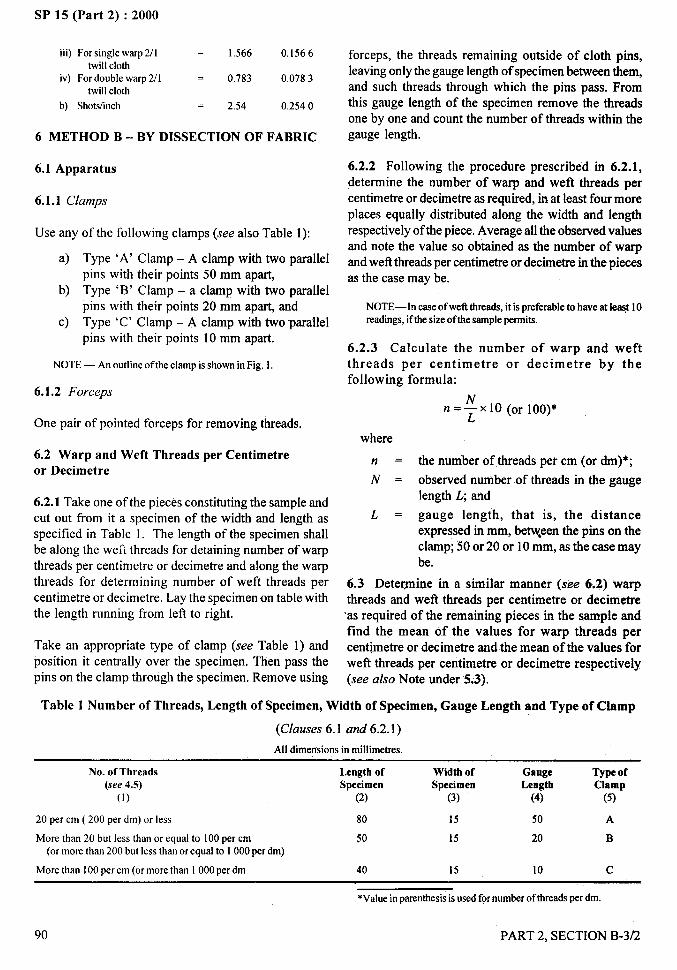
.,,,#t
SP 15 (Part 2) :2000
iii) For single warp 2/1 –— 1.566 0,1566twill cloth
iv) For double warp 2/1 = 0.783 0.0783twill cloth
b) Shot.shnch —— 2.54 0.2540
6 METHOD B – BY DISSECTION OF FABRIC
6.1 Apparatus
6.1.1 Clamps
Use any of the following clamps (see also Table 1):
a) Type ‘A’ Clamp – A clamp with two parallelpins with their points 50 mm apart,
b) Type ‘B’ Clamp – a clamp with two parallelpins with their points 20 mm apart, and
c) Type ‘C’ Clamp – A clamp with tM’oparallelpins with their points 10 mm apart.
NOTE— An outline of the clamp is shown in Fig. 1.
6.1.2 Forceps
One pair of pointed forceps for removing threads.
6.2 Warp and Weft Threads per Centimetreor Decimetre
6.2.1 Take one of the pieces constituting the sample andcut out from it a specimen of the width and length asspecified in Table 1. The length of the specimen shallbe along the wefi threads for detaining number of warpthreads per centimetre or decimetre and along the warpthreads for determining number of weft threads percentimetre or decimetre. Lay the specimen on table withthe length running from left to right.
Take an appropriate type of clamp (see Table 1) andposition it centrally over the specimen. Then pass thepins on the clamp through the specimen. Remove using
forceps, the threads remaining outside of cloth pins,leaving only the gauge length of specimen between them,and such threads through which the pins pass. Fromthis gauge length of the specimen remove the threads
one by one and count the number of threads within thegauge length.
6.2.2 Following the procedure prescribed in 6.2.1,determine the number of warp and weft threads percentimetre or decimetre as required, in at least four moreplaces equally distributed along the width and length
respectively of the piece. Average all the observed valuesand note the value so obtained as the number of warpand weft threads per centimetre or decimetre in the piecesas the case may be.
NOTE—Incaseofweftthreads,it ispreferableto haveat le~t 10readings,if the size of the sample permits.
6.2.3 Calculate the number of warp and weftthreads per centimetre or decimetre by thefollowing formula:
n=~x10 (or 100)*”
where
n = the number of threads per cm (or drn)*;
N = observed number of threads in the gaugelength L; and
L = gauge length, that is, the distanceexpressed in mm, be~een the pins on theclamp; 50 or 20 or 10 mm, as the case may
be.
6.3 Dete~ine in a similar manner (see 6.2) warpthreads and weft threads per centimetre or decimetre‘as required of the remaining pieces in the sample andfind the mean o.f the values for warp threads percent~metre or decimetre and the mean of the values forweft threads per centimetre or decimetre respectively(see also Note under 5.3).
Table 1 Number of Threads, Length of Specimen, Width of Specimen, Gauge Length and Type of Clamp
(Clauses 6.1 and 6.2.1)
All dimensions in millimetres.
No. of Tbreads Length of Width of Gauge(see 4.5)
Type ofSpecimen Specimen Length Clamp
(1) (2) (3) (4) (5)
20 per cm ( 200 per dm) or less 80 15 50 A
More than 20 but less than or equal to 100 per cm 50 15 20 B(or more than 200 but less than or equal to 1000 per dm)
More than 100 per cm (or more than 1000 per dm 40 15 10 c
*Vahsein parenthesisis used for number of threads per dm.
. -----
90 PART 2. SECTION B-3/2
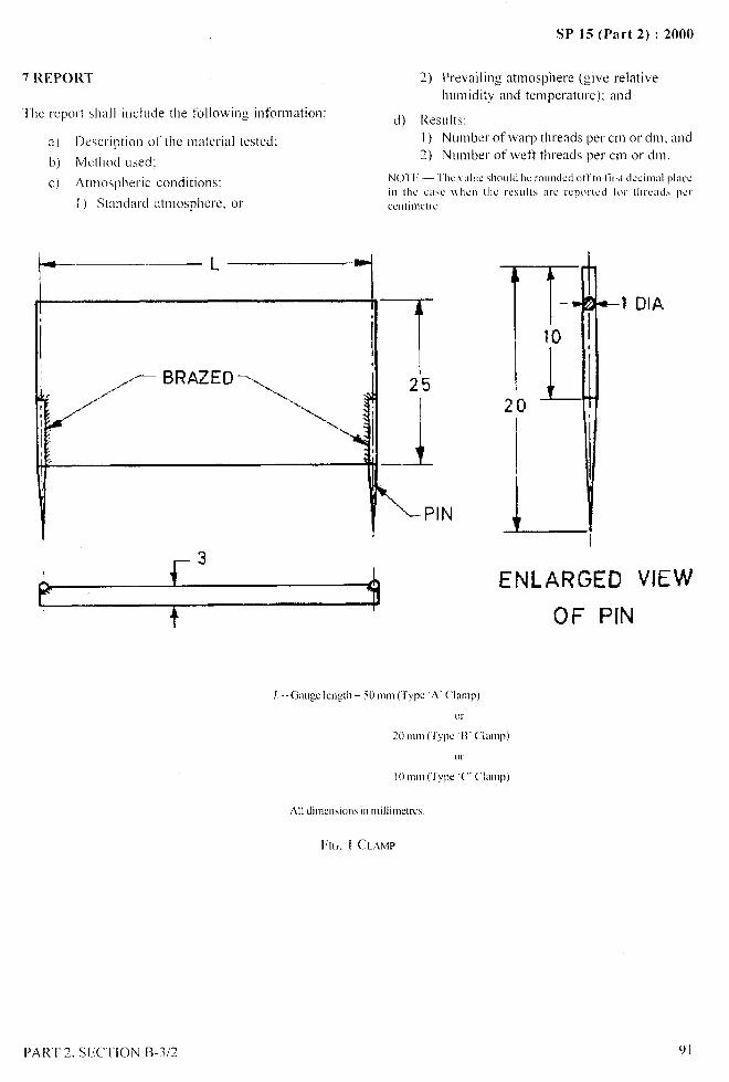
SP 15 (Part 2) :2000
TIIC report shall iuclude the ltillowing information:
a) Description of the material tested:
b) Method used:
c) Atmospheric conditions:
I ) Standard atmosphere, or
I--3
2) Prevailing atmosphere (give relative
humidity and temperature): and
d) Results:1) Number of \varp threacis per Cm or dnl, and~) NLlnlber Of weft threads per cm or dm.
25
-J
T?0
)L
LENLARGED VIEW
OF P[N\ >’,,
\I
All dimensionsi!)millimtres.
FK;. I CLAMP
PART 2, SECTION 13-3/2 9 i
SP 15 (Part 2) :2000
METHODS FOR DETERMINATION OF WEIGHT PER SQUARE
METRE AND WEIGHT PER LINEAR METRE OF FABRICS
(hWC~ : IS 1964: 1970)
1 SCOPE
1.1 It prescribes three Inethods for determination ofweight per square metre and weight per linear metre offabrics.
1.2 Excepting for jute fabrics and tyre cord fabrics,the methods prescribed in this standard areapplicable to all textile fabrics irrespective of theircomposition (that is, whether they are made ofcotton, wool silk or man-made fibres or blends oftwo or more such fibres). manufacturing processesand finishing treatments.
1.2.1 The methods are also applicable to narrow fabrics(see 3.2).
2 PRINCIPLES
In Method A, the material is conditioned to moistureequilibrium in standard atmospheric conditions and thenthe weight is determined; in Method B, oven-dry weight
of the material is determined and then to this is addedthe commercial moisture regain value of the material;and in Method B, the moisture present in the materialis determined ancl then the weight of the fabric iscorrected to the commercial moisture regain value.
3 GENERAL INFORMATION
3.1 Choice of Method
Any of the Methods A, B or C may be used for thedetermination of weight per square metre and weightper linear metre of fabrics depending upon the type ofthe instruments and facilities available.
N(Y1’E–- Method C is a qoic!i and convcoient method for thedcterm!nationot’\\,cighlpcr sqoaremctreandweightper linearmetreoftibrics particularlymhmclcxlin bulktesting/inspection,bot incasegrciltel-~lcc{lfilcyis rcq~llred Method A or B shall be followed.
3.2 Narrow Fabrics
In case of narrow fabrics the weight per unit length shallpreferably be determined from the weights and lengths
of complete rolls, but if this is not possible a tninimumlength of 5 tnetres shall be used.
4 METHOD A—CONDITIONED WEIGHTMETHOD
4.1 Apparatus
4.1.1 Horizontal, Flat, Smooth Tal~le
4.1.2 Graduated Steel Scale
4.1.3 Balance — capable of weighingofo.5 g.
to an accuracy
4.2 Atmospheric Conditions for Conditioning andTesting
4.2.1 Prior to test, the test samples shall be conditionedto moisture equilibrium from dry side in the standardattnosphere of 65+2 percent relative humidity and27+2°C temperature.
NO”rE— The time required for a t’rrbric to reach moistore
cquilibriom depends mainly on:
a) the thickness ofthe fabric or weight per onit area,b) the closeness ofthe weave.c) the hygroscopicity of the textile material comprising the
fabric. andd) type oftinisb given to the fabric.
When the test samples have been exposed to standardatmosphere for at least as much time as given below insuch a way as to expose as far as possible, all portionsof the specimen to the atmosphere they shall be deetnedto have been conditioned satisfactorily for the purposeof this test:
Textile Fabrics having Equilibrium Time
Moisture Regain Values at hours
Standard AtnlospherePercent
Less than 4 6From 4 to 10 12
Above 10 24 to 48
4.2.2 The test shall be carried out in a standardatmosphere (see 4.2. 1).
4.3 Procedure
Take the conditioned test sample (see Note) anddetermine its weight to an accuracy of 0.5g.
--
92
/
PART 2. SECTION B-3/3
Nol I;—11’thefacilities [(1condition the FuIIcut or roll 01t’ah]icarc IIOLwailohlc. CMswatches o! 250 + 2 mm Y full width of’fahl-icincludingsch edges.md conditionthcm.The s\vatclws sIMII
hc so cut m to hc rcprw.mt:ltiveofthe lot.
4.3.1 Determine the length and width of sampled
according to IS 1954:1969 ‘Method for determinationof length and width of fabrics (jkstrevision)’(seeSectionB-311).
4.4 Calculations
Calculate the weight per square metre and
r linear tnetre by the following formula:
weight per
a) ]n case of full length pieces:I ) Weight, in grams, per square
metre (g/m2) =I%X ‘o’
2) Weight. in g,t-ams, per linear
metre (g/m) = ~ x lo~
b) [n case of swatches of 250 mm x full width:1) Weight, in grams, per square
WX 4X10⁵metre (#m~) =
B2) Weight. in syuns, per linear
metre (#m) ==IV X 4 X 1Oq
NO 1’1:— [’onvcrsionquatiom
DJVcigllt in @tll = \l’ciglll in g/nll X ~ f
\\ Ilcrc
11’ = \vcight ofspccimcn in Kg.
.[ = Imgth oi’thic inm.and
h’ == I\ idlh oftidwic in cm.
4.5 Similarly, determine the weight per square metreanti \veigllt per linear metre of at least four tnore testspecimens and determine the average of all the values.
5 METHOD B – OVEN-DRY WEIGHT METHOD
5.1 Apparatus
5.1.1
5.1.2
5.1.3
Suitable for drying sample to constant weight at 105 to110*C.
PARI 2, SEC’1’ION B-3/$.,
SP 15 (Part 2) :2000
5.1.4 Bu/ut7ce
Capable of weighing to an accuracy of 0.5:.
5.2 Procedure
5.2.1 Lay the sample or one end of the cut or roll
smoothly on a flat table. Mark either full width or squareswatches (at least 5) with the help of the scale and T-square of the dimension given below:
a) 250 + 2 mm x fall width of cloth includingselvedges, and
b) 250+2 tnm square.
Cot the swatches so tnarked with the help of sharp scisorsor razor blade. The swatches shall be so chosen as to berepresentative of the lot.
5.2.2 Determine the width of the fabric according toIS 1954:1969 (see Section B-3/l).
5.2.3 Dry the test specimen to constant weight in anoven maintained at 105 to 110°C and weigh to anaccuracy of 0.5 g without removing the specitnen frotnthe oven, the draught being stopped during weighing.
5.3 Calculation
Calculate the weight j)er square tnetre or weight perlinear metre of specimen, at the applicable comtnercialmoisture regain value (.we Note) by using the following
formula:
a) In the case of fhll width swatches:
I) Weight, in grams, per square
4’ W(1OO+R)metre (g/tn2) =
B
2) Weig,ht, in grams, per linear
W(IOO+R)metre (g/m) =
25
b) In case of square swatches:
I ) Weight. in grams. per square
W(lOO+ R)’ 102metre (g/mz) =
625
2) Weight, in grams, per linear
w’ B(loo+R)metre (ghn) =
625
/
SP 15 (Part 2) :2000
Nol’t --- [’o11\e13io11° cqaatioll’
Wci:lll ia @ = \\cight in :Illlz x *
\v]qe~e
W = oven-dry weight of the speci]nen in g.B = width of the fabric in cm, andR = applicable commercial moisture regain,
percent.
~01[: -COtl]tllcrci[lllnOist~lrcregtlillvalllest>lfa[lricssll(lLlldl3cm stipalatcct ia the rclcvatlt lnclian,Standardspecifications tbr thematerialor in dw absenceofsLIch specificationsm agreed to hetweea
[k hoycr aad (he seller.
5.4 Similariy, determine the weight per square metre
and weight per linear metre of at least four more test
specimens and calculate the average of all the values
obtained.
6 METHOD C — MOISTURE REGAIN VALUE
METHOD
6.1 Apparatus
6.1.1 Moish{re Meter
6.1.2 Balurrcc
Capable of weighing to an accuracy of 100 g.
6.2 Procedure
6.2.1 Determine the moisture regain of cloth in the cut
or roll by the use of a suitable moisture meter. Take at
least four readings on the roll at random, along the length
covering different portions across the width.
6.2.2 Weigh the cut or roll to the nearest 100 g.
Determine the weight of the packing material (tare
weight) of the roll to the nearest 100 g and calculate
the net weight of the cloth.
6.2.3 Determine the length and width of the fabric (in
the cut or roll) according to IS 1954:1969 (see section
B-311).
6.3 Calculations
From the moistut-e regain, weight and dimensions of
the sample as determined in 6.2.1 to 6.2.3 Calculate the
weight in grams per square metre and Jveight pcr linear
metre at the applicable commercial moisture regain
using the following formulae:
a)
b)
wWeight, in grams = —
(1OO+R) ~ ,()<
per squareAx BX(IOO+M)
metre (ghn:)
Wx ([00+//)
Weight, in grams.x 103
‘I (I O()+M)per linearmetre (g/m)
NOTE— (’oawrsion qaationWeight io gm = weight ia g/m: . +
where
W’ = net weight of cloth in a cut or roll in kg,
A= length of cloth in a cut or roll in m,
B= fabric width in cm,
R= applicable commercial moisture regain
percent, and
M = average moisture regain percent observed.
NOTE-C~}l]llllercizll moist are regain valoc of fabrics
shoold be as stip Lllated ia the relevaat Iadiaa Staadal-d
specifications for material or in the absence ol’ SLICII
specitlcations as agreed to between the buyer and the seller.
6.4 Similarly, calculate the weight per square metreand weight per linear metre of at least four more testspecimens and calculate the average of all the values soobtained.
7 REPORT
Report shall include the following:
a) Type of fabric tested:
b) Method fol lowed:
c) Number of tests performed:
d) Weight per square metre:
e) Weight per linear metre; and
f) Moisture regain value used (in case of MethodsB and C).
.-
}$,.,,
94 PARI 2, SECTION B-3/3——
SP 15 (Part 2) :2000
DETERMINATION OF MASS OF
JUTE FABRICS
(L’bZi~CZ? : 1S 2387: 1969)
1 SCOPE
It prescribes methods for determination of mass perlinear metre and mass per square metre of jute fabrics.
2 ATMOSPHERIC CONDITIONS FOR TESTING
The test may be carried oL]tin the prevailing atmosphericconditions of the test room.
3 APPARATUS
3.1 For the purpose of this standard, the followingapparatus shall be used:
a) }{orizontal, smooth and flat table;
b) Graduated steel scale;
c) T-square:
d) Balance capable of weighing to an accuracy of0.05 g;
e) Conditioning oven suitable for drying samplesto constant mass at 105* 3°C;
t) A suitable moisture meter; and
g) Balance capable of weighing to an accuracy of100 g.
4 METHOD A — BASED ON OVEN-DRYWEIGHING OF CUT SAMPLE
4.1 Procedure
Based on full width of sample.
4.1.1 Lay one end of cloth from a cut or roll smoothly
on a flat table. By using a steel scale and a T-squaremake a swatch 500+2 mm in length perpendicular toselvedges across the full ~vidtb of the fabric and cut outthe swatch so marked. This shall constitute a test
specimen.
4. I. 1. I Prepare at least five sLIchtest specimens frolm asample lot.
4.1.1.2 For determination of mass per square metre,measuw the width of the specizrren according toIS 1954:1969 ‘Method for determination of length andwidth of fabrics’ given in B-3/l.
PART 2> SECTION B-3/4
4.1.2 Dry the test specimen to constant mass in an ovenmaintained at 105 * 3°C and weigh it to an accuracy of0.2 percent of its mass without removing the specimenfrom the oven, the draught (see Note 1) being stoppedduring weighing, Calculate the mass per linear metreor mass per square metre of the specimen at theapplicable contract regain value (see Note 2) by usingthe following formula:
ZW,,(1OO+R)Mass per linear metre, in g = so
Mass per square metre, in g =2ZW{,(1OO+R)
wwhere
M~ = oven-dry weight of the specimen in g,R = Applicable contract regain percent (see Note
2), andw = width of the specimen in cm.
NOTES1 In order to avoid the risk of oil evaporation, the draogbt in thedryingovenshall notbe continuedthroughout the drying period hotshallbe in operationonly intermittently.
2 Contract regain value of thejote fabrics, shoold be as stipulatedin the relevant Indian Standard speciticatizmsfor the material.
3 Fordeterminationofmass per linearyard or mass per square yardto soit the needsof overseas consumersose the following hmola:
a) Mass per Iincaryard, in oonces = Mass per linear metre.
in g x 0.0322
b)Mass pcrsqoare yard, in oonccs = Mass persqoare nmtre.in g x 0.0322
4.1.3 Similarly determine the mass per linear metre orsquare metre of the remaining test specimens preparedas in 5.1.1.
4.1.4 Calculate the mean of all the values obtained as
above and report it as the mass per linear metre or squaremetre of’the jute fabric in the lot.
4.2 PROCEDURE
4.2.1 Lay one end of cloth from a cut or roll, smoothlyon the flat table and mark at least one 500+2 mm squarespecimen from a cut and three 500+2 mm square
95
SP 15 (Part 2) :2000
specimensfroma rollwiththehelpofa templatetakingdifferentsetsofwarpand wefl threads as far as possibleand cut out the specimens marked. Specimens shouldnot be taken within 50 mm from a selvedge or 200 mmfrom an end of a cut or roll.
4.2.1.1 Prepare at least ten such specimens from asample lot.
4.2.1.2 Measure the width of the fabric according toIS 1954:1969 Method for determination of length andwidth of fabrics’ ~ive in Section B-3/l.
4.2.2 Dry the test specimen to constant mass in an ovenmaintained at 105+ 30”C and weigh it to an accuracyof 0.2 percent of its mass without removing the specimenfrom the oven, the draught (see Note 1 under 5.1.2)
being stopped during weighing. Calculate the mass persquare metre or mass per linear metre at the applicablecontract regain value (see Note 2 under 4.1.2) by thefollowing formulae:
Mass persquaremetre,in g = M, (100 +R)
25
Mass per linear metre, in g = ‘“ “OO+R)x w2500
where
~d .
R=
w=
Oven-dry mass of the specimen in g,Applicable contract regain percent (seeNote 2 under 4.1.2), andFabric width in cm.
NOTE— For determination of massper linear yam or mass persquare yard in ounces see Note 3 under 4.1.2.
4.2.3 Similarly determine the’ mass per square metre ormass per linear metre of the remaining test specimensprepared as in 4.2.1.
4.2.4 Calculate the mean of all the values obtained asabove and report it as the mass per square metre or massper linear metre of jute fabric in the lot.
5 METHOD B ~ BASED ON WEIGHING FULLCUT OR ROLL AND CORRECTING IT TOCONTRACT REGAIN
5.1 Procedure
5.1.1 Determine the moisture regain of cloth in the cutor roll by the use of a suitable moisture meter. Take atleast four readings on the cut and ten readings on theroll at random, along the length covering differentportions across the width.
96
NOTE — lJIRA (Indian Jute Industries’Research Association,Calcutta) Moisture Metre maybe used for the purpose. This meterworks on the principle of measuring the electrical resistance whichchanges with moisture content in the material. The specimen (juteproduct) is placed under the electrode gun having two poles of aspecially designed spring loaded electrode. The small amount ofcurrentpassingthroughthe material held acrossthe electrode polesisamplifiedandrecordedon the meter, calibratedagainst the actualmoistureregain,basedon oven drymethodof the materialmay alsobe used. The instrument shall be operated according to themanufacturer’sinstructions.
5.1.2 Weigh the cut to the nearest 100 g and the roll atleast to the nearest 500 g. Determine the mass of the
packing material (tare mass) of the roll to the nearest100 g and calculate the net mass of cloth in the roll bydeducting the tare mass from the gross mass. Determinethe length and width of the fabric (in the cut or roll)according to IS 1954:1969.
5.1.3 From the moisture regain, mass and dimensionsas determined in 5.1.1 and 5.1.2, calculate the mass ingrams per linear metre or per square metre at theapplicable contract regain (see Note 2 under 4. 1.2) usingthe following formulae:
1000MX 100+RC”a) Mass per linear metre, in g = ~ 100 + R,,
105M 100+Rcb) Mass per square metre, in g = =X
100+Rowhere
M = net weight of cloth in a cut or roll in kg,
1 = length of cloth in a cut or roll in m,
RC = applicable contract regain percent (see Note2 under 5.1.2),
RO = average moisture regain percent observed,and
w = fabric width in cm.
NOTE—For determinationof weight per linear yard or weight pers@re yard in ounces see Note 3 under 5.1.2.
5.1.4 Similarly determine the mass per linear metreand mass per square metre of all the cuts or rolls undertest and calculate their average and reporttheaverages.
6 REPORT
Report shall include the following information:
a) Type of fabric;
b) Method used;
c) Moisture regain value used;
d) Mass per square metre; and
e) Mass per linear metre.
PART 2, SECTION B-3/4
. . - .—
1...:---”
(..\‘%f,,
I
I
..-.
SP 15 (Part 2) :2000
DETERMINATION OF THICKNESS OF..-.
WOVEN AND KNITTED FABRICS8
.. --*(~orwce: IS 7702:1975) ‘1
,#
1 SCOPE a)
1.1 It prescribes a method for determination of thicknessof woven and knitted textile fabrics under a specific
b)pressure.
1.2 This method is not applicable to textile floorcoverings, non-woven textile fabrics, rubber-coated c)
fabrics, pile and raised fabrics.
2 PRINCIPLE
The thickness of a specimen of a woven or knitted fabricis measured as the distance between the reference plateon which the specimen rests and a parallel circularpresser-foot that exerts a specified pressure on the areaunder test.
d)
3 SAMPLING
The sample shall be drawn so as to be representative ofthe lot. Samples drawn in accordance with the procedurelaid down in the material specification or as agreed tobetween the buyer and the seller shall be taken asrepresentative of the lot.
4 ATMOSPHERIC CONDITIONS FORCONDITIONING AND TESTING
The conditioning and testing shall be carried out instandard atmosphere at 65 + 2 percent relative humidityand 27+ 2°C temperature (see also Section B-1/1).
Prior to evaluation, the test sample shall be conditionedto moisture equilibrium in the standard atmosphere(see Note).
NOTE— For guidaocepurposes,it maybe notedthat the minimumtime requiredto reach moisture equilibrium for the varioustypes oftextilematerialshavingmoisture regainvaluesof lessthan 5 percentis about 6 hours while the same for those having moisture regainvalues of more than 5 percent 24 hours.
5 APPARATUS
5.1 Thickness Tester
The instrument used for testing the thickness of fabrics
t shall be provided with the following arrangements:
Interchangeable Presser-Foot — of areaappropriateto the typeof fabricto be tested(seeAnnexA).
Reference Plate — with a plane upper surface
or diameter at least 50 mm greater than that of
the presser-foot.
Means for Moving the Presser-Foot — (in a
direction normal to the upper surface or the
reference plate) with its bearing surface
maintained parallel [to obtain 1 in 500 (slope)]
to the upper surface of the reference plate. The
relevant specific pressure (see Annex A) can
be applied to a test specimen supported on the
plate.
Gauge—for registering the vertical distance
between the bertring surfaces of the presser-foot
and the reference plate to an accuracy of 1
percent for fabrics over 0.1 mm in thickness,
and to 0.001 mm for fabric thickness not
exceeding 0.1 mm.
6 PROCEDURE
6.1 Clean the presser-foot and the reference plate. Check
that the presser-foot shaft moves freely. With the presser-
foot so loaded as to exert the appropriate specified
pressure on the reference plate, set the thickness gauge
to read zero.
NOTE — The areaof the presser-footandthe appliedpressureshallbe agreed betweenthe buyer and the seller (see Annex A).
6.2 Raise the presser-foot and position the sample,
without tension, on the reference plate so that no part of
the area to be measured lies nearer to a selvedge than
150 mm. Ensure that the area chosen for the test is free
from creases. Do not attempt to flatten out any creases,
this is likely to affect the result.
6.3 Lower the presser-foot gently onto the sample and
note the gauge reading after 30 seconds.
6.4 Similarly determine the thickness at 10 places on
the sample so chosen that each such place contains
different warp and weft threads, or courses and wales,
as relevant.I
I
PART 2, SECTION B-3/5 97
I
/
SP 15 (Part 2) :2000.-
7 CALCULATION a) The description of the fabric;
Calculate the arithmetic mean of the measurements b) The area of the presser-foot used;taken in 6.3 and 6.4 to the degree of precisionspecified in 5.1 (d), ,c) The applied pressure; and
8 REPORT d) The maximum, minimum and mean thicknessThe report shall include the following information: of the test sample.
ANNEX A
(Clauses 5.1 and 6.1)
GUIDE TO THE SELECTION OF AREA OF PRESSER-FOOT AND APPLIED PRESSURE
A-1 PRESSER-FOOT
A-1.1 It is recommended that:
a) the ratio of foot diameter to fabric thickness benot less than 5:1, and
b) the area of foot may lie between 500 and10000 mm2.
NOTE—The preferred sizes of the presser-foot are givenbelow:
Area Diametermm’ mm500 25.22
1000 35.682500 56.435000 79.78
10000 112.84
A-2 Applied Pressures
A-2.1 It is recommended that the applied pressure maybe 1, 5 or 10 kPa [Kilopascal (kPa) is approximatelyequivalent to 10 gf/cm2]. ““
).,..,
98
/
PART 2, SECTION B-3/5
SP 15 (Part 2) :2000
DETERMINATION OF BREAKING LOAD AND
ELONGATION OF WOVEN TEXTILE FABRICS
(hwce : IS 1969:1985)
1 SCOPE
1.1 It prescribes methods for determination of breakingload and elongation at break of woven fabrics(conditioned or wet) using grab, ravelled-s~ip and cut-strip methods on constant-rate-of-loading, constant-rate-
of-extension and constant-rate-of-traverse machines.
1.1.1 The methods are applicable to all woven textilefabrics irrespective of their composition (that is,whether they are made of cotton, wool, silk, jute orman-made fibres or blends or two or more such tibres),manufacturing processes and finishing treatments. Itis also applicable to laminated fabrics but not to fabricscoated with rubber or plastics.
2 PRINCIPLE
The specimen is gripped between two clamps of the
tensile testing machine in such a manner that the sameset of yarns is gripped by both the clamps and a continualincreasing load is applied longitudinally to the specimenby moving one of the clamps until the specimen ruptures.Values of breaking load and elongation of the testspecimen are read from the indications of the machine.
3 TERMINOLOGY
For the purpose of this test method, the followingdefinitions shall apply.
3.1 Grab Test
A test in which only a part of the width of the specimenis centrally gripped in the clamps for testing.
3.1.1 Modljied Grub Test
Grab test in which lateral slits are made in the specimento sever all yarns bodering the portion, the strength ofwhich is to be tested; thus reducing the effect of thethreads which are not directly gripped by the jaws to apractical minimum.
3.2 Strip Test
A test in which the full width of the specimen is grippedin the clamps for testing.
PART 2, SECTION B-3/6
3.2.1 Ravened-Strip Test
Strip test in which the specified width of the specimenis obtained by ravening away yarns at the edges.
3.2.2 Cut-Strip Test
Strip test in which the specified width of the specimenis obtained by cutting the fabric.
3.3 Nominal Gauge Length
The length of a specimen under specified pre-tension,measured from nip to nip of the jaws of the holdingclamps in their starting position.
3.4 Time-to-Break
The interval, measured in suitable units, such as seconds,during which the specimen is under a (generallyincreasing) tension, that is, absorbing the energysupplied before the breaking load is reached.
NOTE — Time-to -break does not include the time required toremove slack from the specimen. On machines supplied with anautographic recorder the time to break is indicated by the timeelapsing after the pen registers the initial force sustained by thespecimenuntil the pen registersthe maximum force.
4 SELECTION OF THE TEST
4.1 The type of test to be done in any specific case
depends on what has been specified in the materialspecification or as has been agreed to between the parties.
4.2 Grap Test Method
This method is used when it is desired to determine theeffective strength of the fabric in use, that is, the strengthof the yams in a specific width together with the strengthcontributed by the adjacent yarns. “The method is
particularly suitable for heavy fabrics as well as thosewith high cover factor and in cases where ravening isdifficult or when the ravened-strip starts ravening furtherunder stress.
4.3 Modified Grab Test Method
This method is used especially for fabrics with very highstrength or for fabrics constructions where application
99
)
SP 15 (Part 2) :2000
of stress on ravelled strip specimen produces further un- 1S 6359:1971 ‘Method for conditioning of textiles’ (see—.
ravelling. section B-l/l).
4.4 Ravened-Strip Test Method 6.2 The test shall be carried out in a standard atmosphere(see 6.1).
This method is generally used when it is desired todetermine the breaking load required to rupture specific 6.3 Wet Test — (See 9).width of fabric. This information is useful for comparingthe effective strength of yams in woven fabric with the 7 TESTING APPARATUSstrength of yam before weaving.
7.1 A tensile testing machine provided with the4.4.1 Full Width following arrangements shall be used for testing:
Tapes, ribbons and other narrow fabrics of less than 50mm width are tested full width by this method.
4.5 Cut Strip Test Method/
This method is used in case of heavily sized, felted,laminated fabrics or fabrics in which ravening is noteasy.
5 SAMPLING
5.1 The quantity of fabrics purported to be of onedefinite composition, construction and quality deliveredto one buyer against one despatch shall consitutute thelot.
1
5.2 Sample to test conformity of a lot to a specificationas regards to breaking load and elongation at break shallbe selected so as to be representative of the lot.
5.3 Sample drawn in compliance with the specificationfor the material or as agreed to between the buyer andthe seller shall be held to be representative of the lot.
5.4 Test at least five warpway and five we ftway testspecimens. As far as possible, only one test specimenshall be drawn from a piece in the test sample. Thepieces in the test sample may be drawn from as manybales (or cases) in the lot as possible.
NOTE— Results of tests performed on small samples should beconsidered as representrdiveof that small sample but shouldnot betaken as representativeof the fabricpieceor lotfromwhichthe smallsample was taken.
6 ATMOSPHERIC CONDITIONS FORCONDITIONING AND TESTING
6.1 Prior to test, the specimens shall be conditionedto moisture equilibrium from dry side and tested inthe standard atmosphere of 65 + 2°C percent relativehumidity and 27 + 2°C temperature as laid down in
100
a) Two clamps with the following provisions togrip the specimens:
i)
ii)
Each clamp of the machine shall consistof two metallic jaws and each jaw face shallbe in line both with respect to its mate inthe same clamp and to the correspondingjaws of the other clamp.
Each clamp shall be provided with amechanical device so constructed thatthrough its means a specimen can besecured firmly between the jaws of theclamps so that it does not slip during thetest. Also, the edge of the surface of eachjaws shall be such that it would not cut or
damage the specimen during testing.
NOTE — The faces of the jaws are generally, flat, engraved orcorrugated. To avoid the chances of slippage or damage to thespecimen,packingmaterialslikepaper,felt leather,plasticor rubbersheetmay be used.
b) Means for adjusting the distance between theclamps such that the specimens can be testedat 75 mm gauge length for grab test and at 200mm gauge length for strip test.
c) Means for driving by power one of the pair ofclamps at a specified constant-rate-or-traverse,loading or extension as the case may be, so thatthe test specimen breaks in 20 + 3 seconds(average-time-to-break).
NOTE — If the arrangement for breaking the specimen within20 +3 seconds is not there, the test shall be carried out at aconstant-rate-or-traverse machine (which is very popular andwidely used in India) at the rate of 300 *15 mm/min. In thecase of jute and laminated fabrics, the rate of traverse shall be300 +15 mm per minute for grab and modified grab methodsof test and 450 ● 15 mm/min for ravened-strip and cut stripmethods of test.
d) A scale or dial or authographic recording chartgraduated so as to give load in a newtons(kilograms) and elongation in millimetres.
PART 2, SECTION B-3/6
.
I
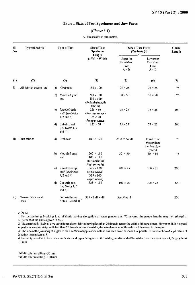
SP 15 (Part 2) :2000
Table 1 Sizes of Test Specimens and Jaw Faces
(Clause 8.1)
All dimensionsin millimetres.
SI Type of Fabric Type ofTest Size of Test Size of Jaw Faces GaugeNo. Specimen (See Note 3 ) Length
Length Ar ?(Mirr) x Width Upper (or Lower (or
Front)Jaw Rear) JawFace Face
AXEI AxB
(1) (2) (3)
i) All fabrics except jute a) Grab test
b) Modified grabtest
ii) Jute fabrics
c) Ravened-striptestlJ(see Notesl,2and4)
d) Cut-striptest(see Notes 1,2and 4)
a) Grab test
b) Modified grabtest
c) Ravened-striptest2J(see Notesl,2and4)
d) Cut-strip test(see Notes 1,2and 4)
iii) Narrow fabrics and Full width (seetapes Notes 1,2 and 4)
(4)
150X 100
200 x 100400 x 100
(forhigh strengthfabrics)
325 x 60(for closeweave)
325 x 70(foropen weave)
325 x 50
(5) (6)
25 x 25 25 x 25
30 x 5(3 50 x 50
75 x 25 75 x 25
75 x 25 75 x 25
180 x 120 25 x 25 to 50 Equal to orbigger than
the front jaw(Col5)
200 x 100 30 x 50 50 x 50400 x 100
(for fabrics ofhigh strength)
325 X 120(closeweave)
325 X 140(openweave)325 x 100 100 X25
100 X25 100 x 25
325 x Full width See Note 4
100 x 25
(7)
75
75
200
200
..-...
75
75
200
200
200
NOTES1 For determining breaking load of fabric having elongation at break greater than 75 percent, tbe gauge lengths may be reduced to50 percent of the values giveninCO17.2 This method is likely to give variable results on fabricshavingless than 20 threads acrossthe width of the specimen. However, if, it is agreedto perfomr a test on strips with less than 20 threads acrossthe width, the actual numberof threads shall be stated in the report.3 The side of thejaw at right anglesto the direction of applicationof load has beentaken as,4 andthat parallel to the direction of application ofload has been taken as B.4 For all types of strip tests, narrow fabrics and types being tested full width, jaw-faces shall be wider than the specimen width by at least10 mm,
‘)Widtb after ravelliog -50 mm.z~widtbafter ravellirrg-100 mm.
PART 2. SECTION B-3/6 101
II1,
I

SP 15 (Part 2) :2000
7.1.1 The load range of the machine shall be such thatall the observed values would lie between 20 and 80percent of the full-scale load. The permissible error inthe machine at any point in this range shall not exceed+1 percent.
7.2 A pair of scissors or a sharp blade, measuring scale,
stop watch, etc.
8 SIZES OF TEST SPECIMENS, JAW FACES ANDMETHODS OF MOUNTING THE SPECIMENS
8.1 Sizes of Test Specimens and Jaw Faces
The sizes of test specimens and jaws faces and differenttypes are given in Table 1.
8.2 Methods of Mounting the Specimen
8.2.1 Grab Test
The test specimen shall be centrally clamped with thesame set of yarns gripped in the two clamps so that thelongitudinal axis of the specimen is at right angles tothe edges of the clamps after pretensioning (see 8.3).Same length of specimen should extend beyond the endsof each jaw.
Example
To ensure that the specimen is centrally clamped withthe same yams in the two clamps, draw a longitudinalline at about 37mm from one edge perfectly parallel tothe lengthwise yarns. Position the specimen in the
lengthwise direction in the clamps such that the linedrawn on the specimen runs adjacent to the sides ofupper and lower edges of the clamps which are nearestto this edge.
8.2.2 Modljled Grab Test
The test specimen shall be centrally clamped with thesame yams gripped in the two clamps after cutting the
slits at the middle portion severing all yarns except thosecomprising the central 25 mm. portion as shown inFig. 1. The specimen should extend through the jawsand project at least 10 mm at each end. The testspecimen having very high strength and requiringspecial mounting device shall be mounted in a mannergiven in Fig. 2.
Example
To ensure that the slits cut on the two sides leave thecentral portion of 25 mm width, draw two longitudinallines at about 37 mm from each edge perfectly parallel
to the lengthwise yam leaving 25 mm width in thecentre. Position the specimen in the lengthwise directionin the clamps such that one of the lines drawn on thespecimen runs adjacent to the sides of upper and loweredges of the clamps which are nearest to that edge.
8.2.3 Ravened and Cut Strip Tests
Mount the test specimen centrally in the clamps with
the longitudinal threads parallel to the direction ofapplication of load, after pre-tensioning (see 8.3).
8.3 Pre-tensioning
8.3.1 Unless the use of a lower tension is necessazy
(see 8.3.2) apply either of the following tensions:
a) a tension equal to 1 + 0.25 percent of probablebreaking load, and
b) the tensioning given in Table 2 appropriate tothe mass per unit area of the fabric under test.
L37
+ . . . : 725 100
TYI1
--~Alldimensionsin millimetres.
FIG. 1 TIS,STSPECIMENFORMODIFIEDGRABTEST
rSTEEL PIN rFABRIC SPECIMEN10 #,130 mm LONG
L-l!KJ L J
-i ‘0 *75-4 50 &
Alldimensionsin millimetres.
FIG. 2 MOUNTINGOFTESTSPECIMEN(HIGH STRENGTHFmucs) — MODIFIEDGRABTESTMETHOD
Table 2 Pre-Tensioning of Specimens
Mass, g/m2 Force, N
Up to and including 150 2
Over 150to and including 500 5
Over 500 10
-–-’i-1
.4
----
]:;,..,,
102 PART 2, SECTION B-3/6
/
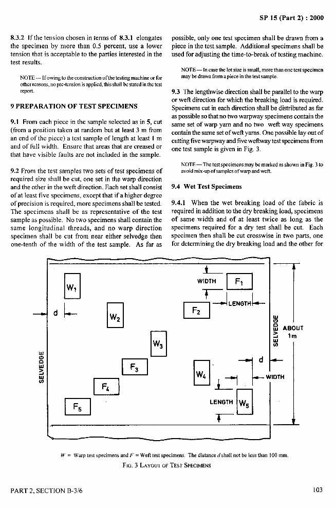
SP 15 (Part 2) :2000
8.3.2 If the tension chosen in terms of 8.3.1 elongates
the specimen by more than 0,5 percent, use a lowertension that is acceptable to the parties interested in thetest results.
NOTE— Ifowing to the construction of the testing machineor forother reasons,no pre-tensionisapplied,this shallbe statedinthe testreport
9 PREPARATION OF TEST SPECIMENS
9.1 From each piece in the sample selected as in 5, cut(from a position taken at random but at least 3 m froman end of the piece) a test sample of length at least 1 mand of full width. Ensure that areas that are creased orthat have visible faults are not included in the sample.
9.2 From the test samples two sets of test specimens ofrequired size shall be cut, one set in the warp directionand the other in the weft direction. Each set shall consistof at least five specimens, except that if a higher degreeof precision is required, more specimens shall be tested.The specimens shall be as representative of the testsample as possible. No two specimens shall contain thesame longitudinal threads, and no warp directionspecimen shall be cut from near either selvedge thenone-tenth of the width of the test sample. As far as
possible, only one test specimen shall be drawn from a .—.4-,piece in the test sample. Additional specimens shall beused for adjusting the time-to-break of testing machine. “
1
,,::.? ,,NOTE— In case the lot size is small, more than one test specimen
,,.
may be drawn from a piece in the test sample,
9.3 The lengthwise direction shall be parallel to the warpor weft direction for which the breaking load is required.Specimens cut in each direction shall be distributed as faras possible so that no two warpway specimens contain thesame set of warp yam and no two weft way specimenscontain the same set of wefi yarns. One possible lay out ofcutting five warpway and five weftway test specimens fi-omone test sample is given in Fig. 3.
NOTE — The test specimens maybe marked as shown in Fig, 3 toavoid mix-upof samples of warp and weft.
9.4 Wet Test Specimens
9.4.1 When the wet breaking load of the fabric isrequired in addition to the dry breaking load, specimensof same width and of at least twice as long as thespecimens required for a dry test shall be cut. Eachspecimen then shall be cut crosswise in two parts, onefor determining the dry breaking load and the other for
+
WIDTHn
F1
‘JLHKjTH~
nF2
w~
nF3
?. 1El,.1=nLENGTH W5
Q - A
W = Warp test specimens and F = Weft test specimens. The distanced shall not be less than 100 mm
FIG. 3 LAYOUTOFTESTSPECIMENS I
PART 2, SECTION B-3/6 103
SP 15 (Part 2) :2000
determining the wet breaking load to ensure that eachpair of specimens contains the same longitudinal yams.For fabrics which shrink excessively when wet, the initial
length of test specimens for the determination of wetbreaking load must be greater than that of specimensfor dry breaking load tests.
9.4.2 The specimens meant for testing wet strength shallbe immersed in distilled water for at least 1 hour. Ifnecessary, 0.5 g/1 of non ionic neutral wetting agent maybe added.
9.4.3 The test should be completed within two minutesafter the removal of test specimens from distilled wateror aqueous solution containing the wetting agent.
10 PROCEDURE
10.1. Set the clamps of the testing machine so that thedistance between them is 75 mm for grab test and200 mm for strip test. Use an additional specimen(9.2) and, after ‘pre-tensioning (if relevant), set themoving clamp in motion at a rate estimated to result inan average time to break as specified (7.1). Note thebreaking load and the time-to-break. Return the movingclamps to its zero position, remove the ends of the brokenspecimen, and repeat the above procedure on twoadditional specimens. If the average time-to-break ofthese three specimens does not fall within 20+3 seconds,discard the results and, using a suitable different rate ofoperation of the moving clamp, repeat the proceduredescribed above. Continue in this way until the average
time-to-break is 20+ 3 s.
10.2 Set the clamps of the testing machine so that thedistance between them is 75 mm for grab test and 200mm for strip test. Take a test specimen, say JVl, asprepared in 9 and insert it in the clamps of the testingmachine so that its longer side is parallel to the direction
of application of load with approximately the samelength of the fabric extending beyond the jaws of at eachend. Secure the test specimen between the jaws of upperclamps. Through the free end of the specimen, applyan appropriate tension as in 8.3 and secure it betweenthe jaws of the other clamps.
10.3 Operate the machine and carry the test to ruptureand record the breaking load and elongation of thespecimen. In case a fabric breaks in two or more stagsrecord only the maximum load.
NOTE— Ifthe specimenslips in thejaws or breaks inside thejaws,the reading should be discarded. If the break takes place within5 mm from the edge ot’eitherof thejaws and the value of the breakis appreciabley below,say 50percentof the averagevalueof all otherbreaks, it should be discarded. If some yarns in a specimen fail tobreak dueto impmpertensioning, the readingshall be discarded. Incaseof rejection anotherspecimen is to be tested in Iieu thereof.
10.4 Open both the clamps and remove the brokenspecimen. Take a fresh specimen and determine its
breaking load and elongation as given in 10.2 and 10.3and repeat the test with the remaining test specimens.
10.5 In a similar manner test weftway specimens.
11 CALCULATIONS
11.1 Calculate the mean breaking load separately forwarpway and we ftway test specimens as follows:
Z LI.z=—
nwhere~ = mean breaking load,
L, = sum of the observed values of breaking load, andn = number of observations.
11.2 Calculate the elongation at break separately forwarpway and weftway test specimens and calculate themean percentage elongation at as follows:
E=E. x 100
n x Gauge Length
where
~ = the mean elongation percent at break,
~ = observed values of elongation at break, ande
n = number of observations.
12 REPORT
The report shall include the following information:
a)
b)
c)
d)
e)
o
g)
Description of the material tested (width oftape if tested full width);
Condition of test (conditioned at standardatmosphere or wet, or both);
Type of test (grab, modified grab, ravened-stripor cut-strip);
Gauge length;
Width of specimen;
Number of the threads in the strip (warp orweft if less than 20 threads); and
Dimensions of jaws.
,..
104
/
PART 2, SECTION B-3/6
1’1,1
I
I

..-.
SP 15 (Part 2) :2000
DETERMINATION OF BURSTING STRENGTH AND BURSTING..4-“1
DISTENSION OF FABRICS: DIAPHRAGM METHOD.!
~:,-.4
1
.,(~ozwce : IS 1966:1975) “:!
The test for tensile strength may be unsuitable for certain type of fabrics, such as knitted materials and lace, and fori
these textiles the measurement of bursting strength provides an alternative criterion of strength. The test may alsobe suitable for woven fabrics which are subjected to bursting pressures in use, for example, pump diaphragms andfilter fabrics. In this test, the specimen breaks across the direction having the least breaking extension, but thebursting strength of the cloth cannot readily be calculated from its tensile strength in this direction since it is influencedby other aspects of the response of the fabric to biaxial stressing.
1 SCOPE
1.1 It prescribes a method for the determination ofbursting strength and bursting distension of woven andknitted fabrics and felts.
1.1.1 This method is applicable to all textile fabrics,irrespective of their composition (that is, whether thefabric is made of cotton, wool, silk, jute or man-madefibres or a blend of two or more such fibres) and history(that is, the manufacturing processes involved and thefinishing treatments).
2 TERMINOLOGY
For the purpose of this standard, the following definitionsshall apply.
2.1 Bursting Strength
The maximum fluid pressure applied to a circularspecimen in distending it to rupture. It is expressed inkilogram force per square centimetre (kgf/cm2) orkilonewtons per square metre (kN/mz).
kgf/cm2NOTE— 1kN/m2 = ——————
102
2.2 Bursting Distension
The distensiofi of a specimen at the bursting pressure. Itis the maximum height in millimetres achieved at thetime of bursting by the centre of the upper surface of thespecimen during the test.
3 PRINCIPLE
A specified area of the sample of fabric under test isclamped over an elastic diaphragm by means of a flatannular clamping ring, and an increasing fluid pressureis applied to the underside of the diaphragm until the
PART 2, SECTION B-3/7
specimen bursts. The operating fluid may be either aliquid or a gas.
4 SAMPLING
4.1 Samples shall be selected so as to be representative
of the lot.
4.2 Samples drawn in accordance with the procedurelaid down in the material specification or as agreed tobetween the buyer and the seller shall be taken asrepresentative of the lot.
5 TEST SPECIMENS
5.1 From the test sample, cut out at least 10 test specimenseach 250 mm x 250mm or 75 mm x 75 mm in size, by
drawing one test specimen (see Note) from each of thepieces constituting the test sample; these shall constitutethe test specimens.
NOTE — More than one test specimen may be cut out of one ormore sample pieces to make up for 10 test specimens.
5.1.1 The system of clamping used generally pertnitstests to be applied without cutting out specimens ( whichmay be resorted to, if desired). The sample of fabricavailable may sometimes be in one or more pieces but itshould be possible to test it at 10 places. The 10 testareas shall be so distributed as to be representative ofthe sample and avoiding selvedges, creased or wrinkledplaces, and other such non-representative areas of thesample.
CAUTION : No portion of the material that has
previously been gripped in the specimen clamp shall beused for a subsequent test.
6 ATMOSPHERIC CONDITIONS FOR CONDI-TIONING AND TESTING
6.1 The conditioning and testing shall be carried out instandard atmosphere at 65+2 percent relative humidity
105
. . —.
SP 15 (Part 2) :2000
and 27=t2°C temperature (see also IS 6359:1971‘Method for conditioning of textiles’ given inSection B-1/1).
6.2 Prior to evaluation, the test specimens shall beconditioned to moisture equilibrium in the standardatmosphere (see Note).
7
“.
NOTE— For guidance purposes, it may be noted that theminimum time required to reach moisture equilibrium for thevarious types of textile materials having moisture regain less than5 percent is about 6 hours while the same for those havingmoisture regain more than 5 percent is 24 hours.
APPARATUS
/.i For Test Diameter of 113 mm
7.1.1 The bursting strength tester shall have a flat baseplate of diameter at least 140 mm, covered by a flatdiaphragm of rubber or similar material (of thicknessnot more than 1 mm). A central hole in the base plateshall allow a controlled increase in fluid pressure to beapplied to the underside of the diaphragm, so that thespecimen bursts in 20*3 seconds. The rate of flow offluid through the hole in the base plate shall not varymore than &20 percent throughout the test.
7.1.2 A clamping ring of internal diameter 113.00+0.05mm and of external diameter 140 mm (Min) shall beprovided with a flat lower surface to hold the specimenfirmly against the diaphragm at all points.
7.1.3 The lower face of the clamping ring maybe lined
with a thin layer of cork or other compressible materialsuitable for the fabric under test; if the face is unlined,its inner edge (or inner periphery) shall have a radius of0.5mm.
7.1.4 Means shall be provided for applying the clampingring with sufficient pressure to prevent the fabricspecimen from slipping during the test. The specimenshall not be damaged by the action of the clamping ring.
7.1.5 Provision shall be made for indicating or recordingthe pressure under the diaphragm at any point in the rangein which the machine is used to an accuracy of* 1percent. Means shall be provided for indicating orrecording the bursting distension of the specimen to an
accuracy of+ 0.25 mm.
7.2 For Test Diameter of 30.5 mm
7.2.1 All conditions shall be the same as in 7.1.1to 7.1.5 except that the diameter of the base plate shall
106
beat least 55 mm and the internal and external diametersof the clamping ring shall be 30.50+ 0.05 mm and55 mm (Min); respectively.
8 PROCEDURE
8.1 Place the test specimen or the area of the sample tobe tested over the diaphragm so that it lies in a flattensionless condition. Clamp it securely by means of
the clamping ring. Increase the pressure smoothly sothat the bursting strength of the fabric is reachedin 20*3 seconds.
8.1.1 Note the bursting strength and the burstingdistension of the specimen. If the-specimen bursts clos~to the edge of the clamping ring, ‘record this fact anddiscard the reading, and carry out another testin lieu thereof.
8.1.2 Repeat the test with other test specimens or at otherplaces on the test sample, as the case may be, to have atleast 10 acceptable measurements.
8.2 Diaphragm Correction
With the same rate of fluid flow as employed in the abovetest, distend the diaphragm, without the presence of aspecimen, but with the clamping ring in position, andnote the pressure required to distend it by an amountequal to the average distension of the specimens. Thepressure is the ‘diaphragm correction’.
9 CALCULATION
9.1 Calculate the arithmetic mean of the measured valuesof bursting strength and from this subtract the diaphragmcorrection.
9.2 Express the arithmetic mean of the burstingdistensions of the specimens selected for the calculationof bursting pressure to the nearest 2 percent.
10 TEST REPORT .
The test report shall include the following information:
a)
b)c)d)
Mean bursting strength in kilogram force persquare centimetre or kilonewtons per squaremetre;Diaphragm correction;Mean bursting distension; andThe type and capacity of the machine, thepressure range at which it was operated, andthe test diameter of the specimen.
PART 2, SECTION B-3/7
?.----
SP 15 (Part 2) :2000
DETERMINATION OF TEAR RESISTANCE
BY THE FALLING PENDULUM METHOD
(Source : IS 6489:1993/1S09290 :1990)
1 SCOPE
It specifies a method for determining the force requiredto propagate a tear, through a specified distance andfrom a specified slit, cut in a test specimen of textilefabric, under specified conditions of loading. The testmethod is suitable for all types of woven fabric (treatedand untreated). The method is not applicable tononwovens or knitted fabrics. Two procedures are givenfor preparing test specimens.
2 TERMINOLOGY
For the purpose of this test method the followingdefinition shall apply.
2.1 Tear Resistance — The average force, in newtons,required to tear a test specimen over a specified length.
3 PRINCIPLE
A rectangular test specimen having a specified precutslit is subjected to a tearing force generated by the energystored in pendulum-sector of specified dimensions. Theenergy expanded in tearing the specimen is used todetermine the tear resistance of the specimen.
4 APPARATUS
4.1 Elements of the Apparatus
The apparatus essentially consists of a frame, mounted
on rigid base, carrying a pendulum and pointer assembly.It shall also satis~ the details as given below with respectto various parts.
4.1.1 Pendulum, preferably formed by a sector of a circle,suitably mounted, free to swing about a horizontal axisfrom bearings of very low frictional resistance.
4.1.2 Augmenting mass, the apparatus shall haveprovision of augmenting masses that maybe attached tothe pendulum sector for further increasing the workingcapacity of the apparatus.
4.1.3 Jaws, a pair of jaws each 16 mm* 0.5 mm deepand 37 mm* 0.5 mm wide, one stationary jaw, fixed
PART 2, SECTION B-3/8
with respect to the base, and the other movable jaw, fixedwith respect to the pendulum. When the pendulum is inthe initial position, ready for the test, the jaws shall beseparated by a distance of 2.8 mm * 0.4 mm and soaligned that the test sample when clamped lied in a planeperpendicular to the plane of oscillation of the pendulumsector with the edges of the jaws gripping the testspecimen in a horizontal line, a perpendicular to whichthrough the axis of suspension of the pendulum sectoris 104 mm + 1 mm long. The angle made by thisimaginary line and the vertical shall be 27.5 + 5°.
4.1.4 Pendulum-sector release mechanism, for holdingthe pendulum-sector in a raised position, and forreleasing it without imparting shock.
4.1.5 Pointer andpointer-stop, for the registering themaximum arc through which the pendulum-sectorswings when released. The pointer is mounted on thesame axis as the pendulum-sector, there being constantfriction just sufficient to stop the pointer at the highestpoint reached by the swing of the pendulum-sector. Theadjustable pointer-stop provides a means for setting thezero of the apparatus.
4.1.6 Levelling screws, for levelling the apparatus.
4.1.7 Cutting die (specimen size), having essentiallythe shape and dimensions shown in figure 1. The die isused to cut out the basic rectangular test specimen thatis 100 mm* 2 mm long and 63 mm* 1 mm wide, plusan additional 8 mm of fabric at the top edge of thespecimen to ensure that the last portion of the fabric istom (not ravened) and 4 mm of fabric at the bottom edgeas an aid to centring it in the jaws.
4.1.8 Means of making a slit, of 20 mm + 0.5 mm in thecentre of the bottom edge of the specimen to initiate thetear. The slit may be cut by the cutting die (5.1.7) or,alternatively, the initial cut may be made by a knife (thatis mounted on the apparatus) when the specimen isin place.
4.2 Capacity and Accuracy
The apparatus shall be of suitable capacity so that thetearing occurs between 20 per6ent and 80 perdent of thefull-scale force. It shall also meet the followingrequirements:
107
..
}.p&.,.

SP 15 (Part 2) :2000
Scale error < 10/0
Zero error < 0.5°/0 of till scale loadZero stability < 10/Oof full scale load
Pointer friction < 3 and >2 scale divisionsPendulum friction > 35 oscillations
4.3 Adjustment and Maintenance
The apparatus shall be maintained properly and adjustedregularly in accordance with the instructions of themanufacturer. A brief description of adjustment andmaintenance of an apparatus functioning on the aboveprinciple is given in Annex A.
5 PREPARATION OF TEST SPECIMENS
5.1 Sampling
The test sample shall be taken from a laboratory bulksample that is representative of the lot to be tested. Thetest sample shall not be cut within 2 m of the ends of apiece nor closer than 50 mm to a selvedge.
The critical dimensions of the test specimen are thedistance of 43 mm & 0.5 mm that is to be tom during thetest, and the distance above the clamp of the end of thepre-cut slit of 4.0 mm+ 0.5 mm.
For method A, cut specimens as shown in Fig. 1. Formethod B, cut specimens 100 mm + 2 mm by63 mm * 1 mm.
FIG. 1 CUTTINGDE
NOTE— For some apparatus the appropriate dimensions vary,particularly in the width of the test specimen. If specimens withwidths other than those specified are used, this shall be stated inthe test report
5.2 Test Specimens
One set of not less than five specimens shall be cut foreach direction to be tested, using the cutting die (4.1.7).
The set for the warp tear tests (that is tearing across the
warp threads) shall have the shorter dimension parallelto the weft threads, and the set for weft tear tests
(thaf is tearing across the wetl threads) shall have the
shorter dimension parallel to the warp threads. Each setof specimens shall be cut from the sample in such amanner that no two specimens in the set include the same
threads. In preparing the specimens, care shall be taken
to align the threads running in the short direction parallel
to the die so that when the slit is cut, the subsequent tear
will take place between these threads and not across them.This precaution is most important when testing bowed
fabrics.
6 ATMOSPHERE FOR CONDITIONING ANDTESTING
The specimens shall be conditioned to moisture
equilibrium and testing shall be conducted standardatmospheres at 65*2 percent relative humidity and
27* 2°C temperature (see Section B-l/l).
7 PROCEDURE
7.1 Preparation of Apparatus
7.1.1 Before testing, level the apparatus with thelevelling screws (4.1.6) and check both the equilibrium
position of the pendulum-sector and zero reading.
7.1.2 Select the capacity of the apparatus (4.2) according
to the fabric under test, so that the specimens tear
between 20 percent and 80 percent of the full-scale value.
Carry out a preliminary test, if necessary, to determinethe appropriate range.
7.2 Test Procedure for Method A
7.2.1 Raise the pendulum-sector (4,1.1) to the startingposition. Secure it by the pendulum-sector release
mechanism (4. 1.4) and set the pointer against its stop
(4.1.5).
7.2.2 Clamp a specimen securely in the jaws (4.1.3) sothat it is centred with the botton edge set against the stopsand the upper edge parallel to the top of the jaws. Closethe jaws by tightening the setting screws, usingapproximately the same tension on both, whereapplicable operate the knife (4. 1.8) to make the initial
108 PART 2, SECTION B-3/8
4.———.
SP 15 (Part 2) :2000
slit in the lower edge of the specimen. The specimen
shall lie free with its upper edge directed towards thependulum-sector so as to ensure a shearing action.
7.2.3 Depress the pendulum-sector release mechanism
as far as it will go and hold it down until tearing is
completed (This is particularly important in order to
prevent the pendulum stop from interfering with the
initial swing of the pendulum-sector). Catch the
pendulum-sector by hand on the return swing without
disturbing the position of the pointer.
7.2.4 Record the position of the pointer as indicated
by the nearest whole scale division for the capacityused.
7.2.5 Repeat operations 7.2.1 to 7.2.4 on the remainingtest specimens.
7.2.6 Discard readings obtained when the specimen slipsin the jaws or where tearing deviates beyond the base ofthe slit in such a way that the tear is not completed inthe notch at the top of the specimen.
7.3 Test Procedure for Method B
Carry out the procedure generally as describedin 7.2 but, after mounting the specimen on the apparatus,make a slit using the means provided (4.1.8).
8 EXPRESSION OF RESULTS ..-/.. .
8.1 Record the Tearing Force in Newtons,:
~~ .-.--F
NOTE — Dependingon the type of apparatus used, this may meanmultiplying the scale reading obtained by an appropriate factoras specified by the manufacturer of the test apparatus.
8.2 Calculate and record the average force, in newtons,required to tear the test specimens across:
– the warp threads; and– the weft threads.
8.3 If required, calculate the coefficients of variation ofthe results.
9 TEST REPORT
The test report shall include the following:
a)
b)
c)
d)
e)
that the test was conducted in accordance withthe method A or B;
the type of material tested;
the number of readings in both warp and weftdirections;
the individual values and the average tearingforce, in newtons, for each direction of tear and,if required, the coefficient of variation for eachdirection of tear; and
the number of tests rejected because ofcrosswise tearing or for other reasons.
/
PART 2, SECTION B-3/8
I
109
I
I
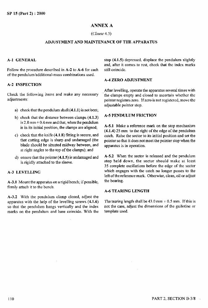
, 4,——
SP 15 (Part 2) :2000
ANNEX A
(Clause 4.3)
ADJUSTMENT AND MAINTENANCE OF THE APPARATUS
A-1 GENERAL
Follow the procedure described in A-2 to A-6 for eachof the pendulum/additional-mass combinations used.
A-2 INSPECTION
Check the followingadjustments:
items and make any necessary
a)
b)
c)
d)
check that the pendulum shaft (4.1.1) is not bent;
check that the distance between clamps (4.1.3)is 2.8 mm + 0.4 mm and that, when the pendulum
is in its initial position, the clamps are aligned;
check that the knife (4.1 .8) fi~ing is secure, andthat cutting edge is sharp and undamaged (the
blade should be situated midway between, andat right angles to the top of the clamps); and
ensure that the pointer (4.1.5) is undamaged andis rigidly attached to the sleeve.
A-3 LEVELLING
A-3.1 Mount the apparatus on a rigid bench; if possible,firmly attach it to the bench.
A-3.2 With the pendulum clamp closed, adjust theapparatus with the help of the levelling screws (4.1.6)so that the pendulum hangs vertically and the indexmarks on the pendulum and base coincide. With the
stop (4. 1.5) depressed, displace the pendulum slightlyand, after it comes to rest, check that the index marksstill coincide.
A-4 ZERO ADJUSTMENT
After Ievelling, operate the apparatus several times withthe clamps empty and closed to ascertain whether thepointer registers zero. If zero is not registered, move theadjustable pointer stop.
A-5 PENDULUM FRICTION
A-5.1 Make a reference mark on the stop mechanism(4.1.4) 25 mm to the right of the edge of the pendulumcatch. Raise the sector to its initial position and set the
pointer so that it does not meet the pointer stop when theapparatus is in operation.
A-5.2 When the sector is released and the pendulumstop held down, the sector should make at least35 complete oscillations before the edge of the sectorwhich engages with the catch no longer passes to theleft of the reference mark. Otherwise, clean, oil or adjustthe bearing.
A-6 TEARING LENGTH
The tearing length shall be 43.0 mm + 0.5 mm. If this isnot the case, adjust the dimensions of the guilotine ortemplate used.
---
110 PART 2, SECTION B-3/8
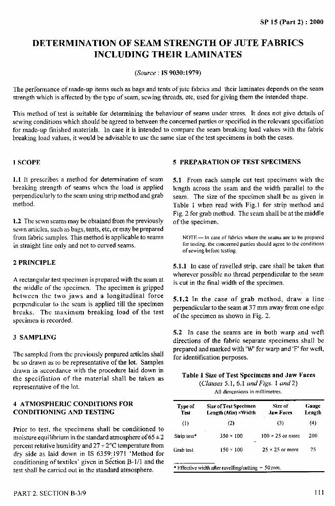
&—.-.—
..-.
SP 15 (Part 2) :2000
DETERMINATION OF SEAM STRENGTH OF JUTE FABRICS=.
INCLUDING THEIR LAMINATESt
(&x.free : IS 9030:1979) “’”-””1,
The performance of made-up items such as bags and tents of jute fabrics and their laminates depends on the seamstrength which is affected by the type of seam, sewing threads, etc, used for giving them the intended shape.
This method of test is suitable for determining the behaviour of seams under stress. It does not give details ofsewing conditions which should be agreed to between the concerned parties or specified in the relevant specificationfor made-up finished materials. In case it is intended to compare the seam breaking load values with the fabricbreaking load values, it would be advisable to use the same size of the test specimens in both the cases.
1 SCOPE
1.1 Itprescribes a method for determination of seam
breaking strength of seams when the load is appliedperpendicularly to the seam using strip method and grabmethod.
1.2 The sewn seams may be obtained from the previouslysewn articles, such as bags, tents, etc, or may be preparedfrom fabric samples. This method is applicable to seamsin straight line only and not to curved seams.
2 PRINCIPLE
A rectangular test specimen is prepared with the seam atthe middle of the specimen. The specimen is grippedbetween the two jaws and a longitudinal forceperpendicular to the seam is applied till the specimenbreaks. The maximum breaking load of the testspecimen is recorded.
3 SAMPLING
The sampled from the previously prepared articles shallbe so drawn as to be representative of the lot. Samplesdrawn in accordance with the procedure laid down inthe specification of the material shall be taken asrepresentative of the lot.
4 ATMOSPHERIC CONDITIONS FORCONDITIONING AND TESTING
Prior to test, the specimens shall be conditioned tomoisture equilibrium in the standard atmosphere of 65 + 2
percent relative humidity and 27+ 2°C temperature fromdry side as laid down in IS 6359:1971 ‘Method forconditioning of textiles’ given in S<ction B- 1/1 and thetest shall be carried out in the standard atmosphere.
5 PREPARATION OF TEST SPECIMENS
5.1 From each sample cut test specimens with thelength across the seam and the width parallel to the
seam. The size of the specimen shall be as given in
Table 1 when read with Fig. 1 for strip method and
Fig. 2 for grab method. The seam shall be at the middle
of the specimen.
NOTE— In case of fabrics where the seams are to be preparedfor testing, the concerned parties should agree to the conditionsof sewing before testing.
5.1.1 In case of ravened strip, care shall be taken thatwherever possible no thread perpendicular to the seam
is cut in the final width of the specimen.
5.1.2 In the case of grab method, draw a line
perpendicular to the seam at 37 mm away from one edge $.
of the specimen as shown in Fig. 2.
5.2 In case the seams are in both warp and weft
directions of the fabric separate specimens shall be
prepared and marked with ‘W’ for warp and ‘F’ for weft,
for identification purposes.
Table 1 Size of Test Specimens and Jaw Faces(Clauses 5.1,6.1 and Figs. 1 and2)
All dimensions in millimetres.
Type of Size of Test Specimen Size of GaugeTest Length (Mirr)xWidth Jaw Faces Length
(1) (2) (3) (4)
Striptest* 350 x 100 100 x 25 or more 200
Grab test 150 x 100 25 x 25 or more 75
* Effectivewidth afterravellinticuttirrrz = 50 mm.
PART 2, SECTION B-3/9
/
I
I1,’,
I

—.SP 15 (Part 2) :2000
6 TESTING MACHINE
6.1 A tensile testing machine provided with the
following arrangements shall be used:
a) Two clamps, each of which shall:
1) consist of two metallic jaws (see Table 1)
and each jaw face shall be in line both withrespect to its mate in the same clamp and
to the corresponding jaws of the otherclamp; and
2) be provided with a mechanical device
so constructed that through its means a
specimen can be secured firmly betweenthe jaws of the clamps so that it doesnot slip during the test. Also, the edge
of the surface of each jaw shall be suchthat it would not cut or damage thespecimen during testing.
NOTE— The faces of the jaws are generally flat, engravedorcorrugated. To avoid the chancesof slippageor damageto thespecimen,packingmaterialslikepaper,fel~leather,plasticor robbersheet may be used.
b) Means for adjusting the distance between theclamps.
c) Means for driving by power one of the pair ofclamps at a specified constant-rate-of-traverse,loading or elongation, as the case may be,
so that the test specimen breaks in 20seconds + 10 seconds.
NOTE— If the arrangement for breaking the specimen within20 seconds +10 seconds is not there, the test shall be carriedout at a constant-rate-of-traverse machine (which is verypopular and widely used in India) at the rate of 300 mm+ 15mm/min. In case of j ute fabrics, the rate-of-traverse shall be300 mm+ 15 mm hnin for grab test and 460 mm+ 15 mnr/min for ravened-strip and cut-strip method of test.
d) A scale or dial or autographic recording chartgraduated so as to give load in newtonslkilograms.
6.1.1 The load range of the machine shall be such that
all the observed values would lie between 10 and
90 percent of the full-scale load. The permissible error
in the machine at any point in this range shall not
exceed +1 percent. “
6.2 A pair of scissors or a sharp blade, measuring scale,stop watch, etc.
112
/
PORTION FOR
REVELLING /
CtJTTING
SEAM
4 25 l+__504 25 ~
All dimensions in millimetres.
FIG. 1 SHAPEANDDIMENSIONSOFTESTSPECIMENS
(STRIPMETHOD)
~“I.IIIIIIII
---+---.-- - -----------—. — .—. .,----- ------------
-100 mm FINALWIDTH
-SEAM
>
All dimensions in millimetres.
FIG. 2 SHAPEANDDIMENSIONSOFTESTSPECIMENS
(GIW METHOD)
PART 2, SECTION B-3/9
II
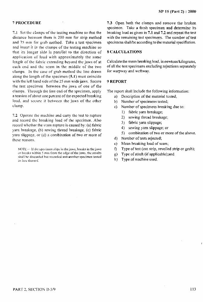
,—-
7PROCEDURE
7.1 Set the clamps of the testing machine so that the
distance between them is 200 mm for strip methodand 75 mm for grab method. Take a test specimen
and insert it in the clamps of the testing machine sothat its longer side is parallel to the direction ofapplication of load with approximately the samelength of the fabric extending beyond the jaws of at
each end and the seam in the middle of the two
clamps. [n the case of grab method the line drawnalong the length of the specimen (5.1) must coincidewith the left band side of the 25 mm wide jaws, Secure
the test specimen between the jaws of one of theclamps. Through the free end of the specimen, apply
a tension of about one percent of the expected breakingload, and secure it between the jaws of the other
clamp.
7.2 Operate the machine and carry the test to rupture
and record the breaking load of the specimen. Also
record whether the saam rupture is caused by: (a) fabricyarn breakage, (b) sewing thread breakage, (c) fabric
yarn slippage, or (d) a combination of two or more of
these reasons.
N()’lE-lt’the specimen slips in the jaws, breaks in the jawsc>rbreaks within 5 mm from the edge of the.jaws, the resllltSsha!l be discarded but recorded and another specimen testedifl /Ie II thereof.
SP 15 (Part 2) :2000
7,3 Open both the clamps and remove the brokenspecimen. Take a fresh specimen and determine itsbreaking load as given in 7.1 and 7.2 and repeat the test
with the remaining test specimens. - The number of testspecimens shall be according to the material specification.
8 CALCULATIONS
Calculate the mean breaking load, in newtons/kilograms,of all the test specimens excIuding rejections separatelyfor warpway and we ftway.
9 REPORT
The report shall include the following information:
a)
b)
c)
d)
e)
o
g)h)
Description of the material tested;
Number of specimens tested;
Number of specimens breaking due to:
1) fabric yam breakage;
2) sewing thread breakage;
3) fabric yam slippage;
4) sewing yam slippage; or
5) combination of two or more of the above.
Number of tests rejected;
Mean breaking load of seam;
Type of test (cut strip, revelled strip or grab);
Type of stitch (if applicable);and
Type of machine used.
“ --4$
PART 2, SECTION B-3/9 113
, II !,
I
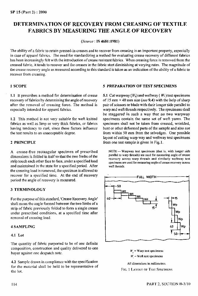
SP 15 (Part 2) :2000
DETERMINATION OF RECOVERY FROM CREASING OF TEXTILE
FABRICS BY MEASURING THE ANGLE OF RECOVERY
(Source : IS 4681:1981)
The ability of a fabric to retain pressed-in creases and to recover from creasing is an important property, especiallyin case of apparel fabrics. The need for standardizing a method for evaluating crease recovery of different fabricshas been increasingly felt with the introduction of crease resistant fabrics. When creasing force is removed from the
creased fabric, it tends to recover and the creases in the fabric start diminishing at varying rates. The magnitude ofthe crease recovery angle as measured according to this standard is taken as an indication of the ability of a fabric torecover from creasing.
1 SCOPE
1.1 It prescribes a method for determination of creaserecovery of fabrics by determining the angle of recoveryafter the removal of creasing force. The method isespecially intended for apparel fabrics.
1.2 This method is not very suitable for weft knittedfabrics as well as limp or very thick fabrics, or fabricshaving tendency to curl, since these factors influencethe test results to an unacceptable degree.
2 PRINCIPLE
A crease-free rectangular specimen of prescribeddimensions is folded in half so that the two limbs of thestrip touch each other face to face, under a specified loadand maintained in the state for a specified period. Afterthe creasing load is removed, the specimen is allowed torecover for a specified time. At the end of recoveryperiod the angle of recovery is measured.
3 TERMINOLOGY
For the purpose of this standard, ‘Crease Recovery Angle’shall mean the angle formed between the two limbs of astrip of fabric previously folded to form a single creaseunder prescribed conditions, at a specified time afierremoval of creasing load.
4 SAMPLING
4.1 Lot
The quantity of fabric pu~orted to be of one definitecomposition, construction and quality delivered to onebuyer against one despatch note.
4.2 Sample drawn in compliance with the specificationfor the material shall be held to be representative ofthe lot.
114
5 PREPARATION OF TEST SPECIMENS
5.1 Cut warpway (WP)and weflway ( W,) test specimensof 15 mm x 40 mm size (see 9.4) with the help of sharppair of scissors or blade with their longer side parallel towarp and weft threads respectively. The specimens shallbe staggered in such a way that no two warpwayspecimens contain the same set of weft yarns. Thespecimens shall not be taken from creased, wrinkled,bent or other deformed parts of the sample and also notfrom within 50 mm from the selvedges. One possible
layout of cutting warp way and we ftxvay test specimensfrom one test sample is given in Fig. 1.
NOTE — Warpway test specimens (that is, with longer sideparallel to warp threads) are used for measuring angle of creaserecovery across warp threads and similarly weftway testspecimens are used for measuring angle of crease recovery acrosswefi threads.
~FIJLL ‘lDTH
+50
J=+w-SJI ,
r,5J 1
15
Wp
Wp
Wp
40 Wp
50
Wr= Warp test specimens
W,= Wett test specimens
All dimensions in millimetres.
FIG. 1 LAYOUTOFTESTSPECIMENS
PART 2, SECTION B-3/10
.-. .
/
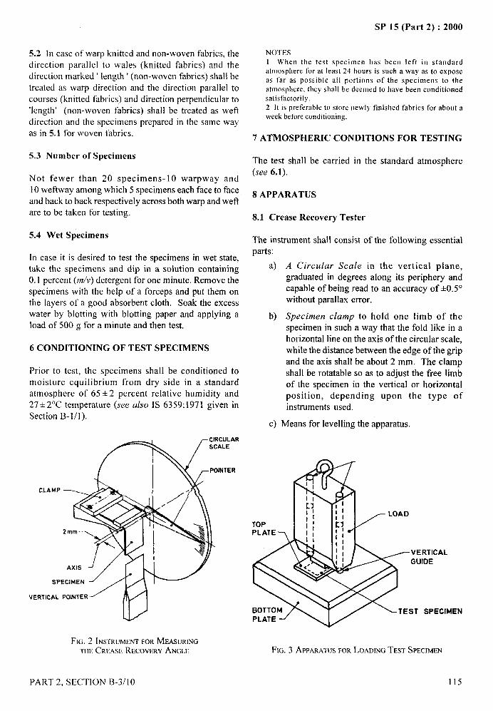
SP 15 (Part 2) :2000
5.2 In case of warp knitted and non-woven fabrics, thedirection parallel to wales (knitted fabrics) and thedirection marked ‘ length ‘ (non-woven fabrics) shall be
treated as warp direction and the direction parallel tocourses (knitted fabrics) and direction perpendicular to‘length’ (non-woven fabrics) shall be treated as weft
direction and the specimens prepared in the same wayas in 5.1 for woven fabrics.
5.3 Number of Specimens
Not fewer than 20 specimens-10 warpway and10 weftway among which 5 specimens each face to faceand back to back respectively across both warp and wetlare to be taken for testing.
5.4 Wet Specimens
In case it is desired to test the specimens in wet state,take the specimens and dip in a solution containing0.1 percent (WV) detergent for one minute. Remove thespecimens with the help of a forceps and put them onthe layers of a good absorbent cloth. Soak the excesswater by blotting with blotting paper and applying aload of 500 g for a minute and then test.
6 CONDITIONING OF TEST SPECIMENS
Prior to test, the specimens shall be conditioned tomoisture equilibrium from dry side in a standardatmosphere of 65+2 percent relative humidity and27+ 2°C temperature (see also IS 6359:1971 given inSection B-l/l ).
AR
R
CLAM.P
SP
VERTICAL
FIG. 2 INSTRUMENTFORMEASURINGTHECRF.ASERECOVERYANGLE
NOTES
I When the test specimen has been left in standardatmosphere for at least 24 hours is such a way as to exposeas far as possible all portions of the specimens to theatmosphere. they shall be deemed to have been conditioned
‘, .----?y
satisfactorilyy.2 It is preferable to store newly finished fabrics for about aweek before conditioning.
7 ATMOSPHERIC CONDITIONS FOR TESTING
The test shall be carried in the standard atmosphere
(see 6.1).
8 APPARATUS
8.1 Crease Recovery Tester
The instrument shaIl consist of the following essentialparts:
a) A Circular Scale in the vertical plane,graduated in degrees along its periphery andcapable of being read to an accuracy of &0.5°without parallax error.
b) Specimen clamp to hold one limb of thespecimen in such a way that the fold like in ahorizontal line on the axis of the circular scale,while the distance between the edge of the grip
and the axis shall be about 2 mm. The clampshall be rotatable so as to adjust the free limbof the specimen in the vertical or horizontalposition, depending upon the type ofinstruments used.
c) Means for levelling the apparatus.
RTICALIDE
SPECIMEN
FIG. 3 APPARA~USFORLOADINGTEST SPECMETi
PART 2, SECTION B-3/10 115
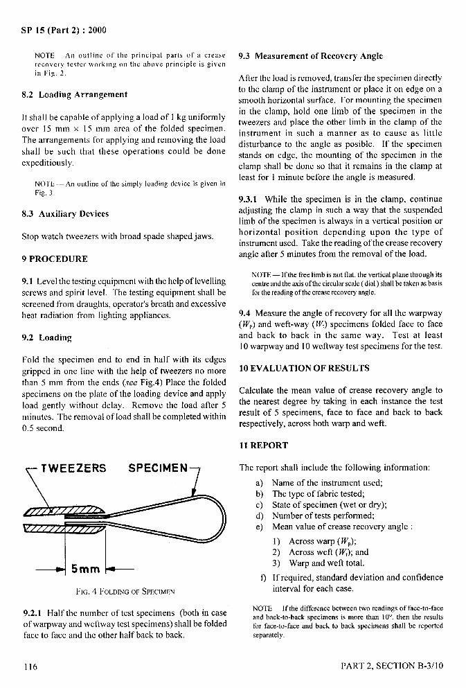
SP 15 (Part 2) :2000._..
NOTE—An outline of the principal parts of a creaserecovery tester wrrr!iiog on the above principle is givenin Fig. 2.
8.2 Loading Arrangement
It shall be capable of applying a load of 1 kg uniformly
over 15 mm x 15 mm area of the folded specimen.
The arrangements for applying and removing the load
shall be such that these operations could be doneexpeditiously.
NOTE — An outline of the simply loading device is given inFig, 3.
8.3 Auxiliary Devices
Stop watch tweezers with broad spade shaped jaws.
9 PROCEDURE
9.1 Level the testing equipment with the help of levelling
screws and spirit level. The testing equipment shall be
screened from draughts, operator’s breath and excessiveheat radiation from lighting appliances.
9.2 Loading
Fold the specimen end to end in half with its edges
gripped in one line with the help of tweezers no more
than 5 mm from the ends (see Fig.4) Place the folded
specimens on the plate of the loading device and apply
load gently without delay. Remove the load after 5
minutes. The removal of load shall be completed within
0.5 second.
‘1TWEEZERS SPECIMEN 7
.-+ 5mm k-----
Ft(;. 4 FOLDINGOF SPECIMEN
9.2.1 Half the number of test specimens (both in caseof warpway and weftway test specimens) shall be foldedface to face and the other halfback to back.
9.3 Measurement of Recovery Angle
After the load is removed, transfer the specimen directlyto the clamp of the instrument or place it on edge on asmooth horizontal surface. For mounting the specimen
in the clamp, hold one limb of the specimen in thetweezers and place the other limb in the clamp of theinstrument in such a manner as to cause as littledisturbance to the angle as posible. If the specimenstands on edge, the mounting of the specimen in the
clamp shall be done so that it remains in the clamp atleast for 1 minute before the angle is measured.
9.3.1 While the specimen is in the clamp, continueadjusting the clamp in such a way that the suspendedlimb of the specimen is always in a vertical position orhorizontal position depending upon the type ofinstrument used. Take the reading of the crease recoveryangle after 5 minutes from the removal of the load.
NOTE — If the free limb is not flat, the vertical plane through itscentreandthe axisof the circularscale ( dial ) shall be taken as basisforthe readingof the creaserecovery angle.
9.4 Measure the angle of recovery for all the warpway(IV,) and weft-way (IY,) specimens folded face to faceand back to back in the same way. Test at least10 warpway and 10 we ftway test specimens for the test.
10 EVALUATION OF RESULTS
Calculate the mean value of crease recovery angle tothe nearest degree by taking in each instance the testresult of 5 specimens, face to face and back to backrespectively, across both warp and weft.
11 REPORT
The report shall include the following information:
a)b)c)d)e)
o
Name of the instrument used;The type of fabric tested;State of specimen (wet or dry);Number of tests performed;Mean value of crease recovery angle :
1) Across warp (W,);2) Across weft ( W,); and3) Warp and weft total.
If required, standard deviation and confidenceinterval for each case.
NOTE— If the difference between two readings of face-to-faceand back-to-back specimens is more than 10°, then the resultsfor face-to-face and back to back specimens shall be reportedseparately.
–“?.
116
/
PART 2, SECTION B-3/10

SP 15 (Part 2) :2000
DETERMINATION OF
PILLING RESISTANCE OF FABRICS
(Source : IS 10971 :1984)
Fabrics made from certain fibres and fibre blends may develop during the course of wear tufts of entangled fibres,
attached to the surface of the cloth and looking like small pills. Although a number of methods have been developedfor determining the pilling properties of fabrics, it is difficult to simulate the wear conditions by any single machine.Testing of this characteristic is important especially for fabrics meant for garments like sweaters, shirts, blouses,Iingeries, trousers, suits and skirts.
1 SCOPE
It prescribes a method for determination of pillingresistance of fabrics by tumble type pilling tester. Thismethod may not be suitable for fabrics containing fancyyarn like stub yarn, gimp yarn and fleece yam.
2 PRINCIPLE
The fabric samples are mounted on rubber tubes andput in a cubical box revolving at a known speed for afixed time. The samples are then removed and comparedagainst standards.
3 SAMPLING
The samples for test shall be drawn as laid down in thematerial specification or as agreed to between the buyerand the seller. The samples drawn shall be representativeof the lot.
4 ATMOSPHERIC CONDITIONS FORCOND1TIONING AND TESTING
4.1 Prior to evaluation the samples shall beconditioned to moisture equilibrium in the standard
atmosphere at 65+2 percent relative humidity and a
temperature of 27 + 2°C as laid down in IS 6359:1971‘Method for conditioning of textiles’ given in SectionB-l /1. The test shall also be carried out in the standardatmosphere.
5 APPARP TUS
5.1 Tumble Pilling Tester
Having cubical boxes of 225 mm internal side length.The inner walls of the boxes shall be lined with 3 mmthick cork lining. The mass/cm2 of the cork lining shallbe 0.085 g. The boxes shall be capable of rotating at aconstant speed of 60 rev/rein about a horizontal axispassing through the centres of two opposite faces. The
PART 2. SECTION B-3/l 1
tester shall be provided with arrangements for stoppingit after pre-determined number of revolutions.
NOTE — The cork lining shall be replaced only when it appearsto be severely worn out or soiled.
5.2 Template for Cutting Specimens — See Fig. 1.
t- 500 d13
~
4 i—{
.
. 2 SLITS
? f< >
!LJ MATERIAL :BRASS
All dimensions in millimetres.
FIG. 1 TEMPLATEFORTESTSPECIMENS
5.3 Rubber Tubes
Of 150 mm length, 32 mm outer diameter and 3.2 mmwall thickness, having Shore A hardness of 55 to 60degrees.
5.4 Specimens Mounting Accessories
Comprising ~g, metal cylinder, etc, as shown in Fig. 3.
5.5 Photographic Rating Standards
A set of 5 photographs, 110 mm x 95 mm in size,numbered as 1 to 5 showing varying degrees of pillingfrom ‘very severe pilling’, to ‘no pilling’, as given inAnnex A.
/
6 PREPARATION OF TEST SPECIMENS
6.1 Place the fabric facing downwards on a plainsurface and on it place the template (see Fig. 1) withits longer edges along the weft direction. Draw lineswith the help of a pencil around the edges and in theslits of the template. Then cut the fabric along the outer
117
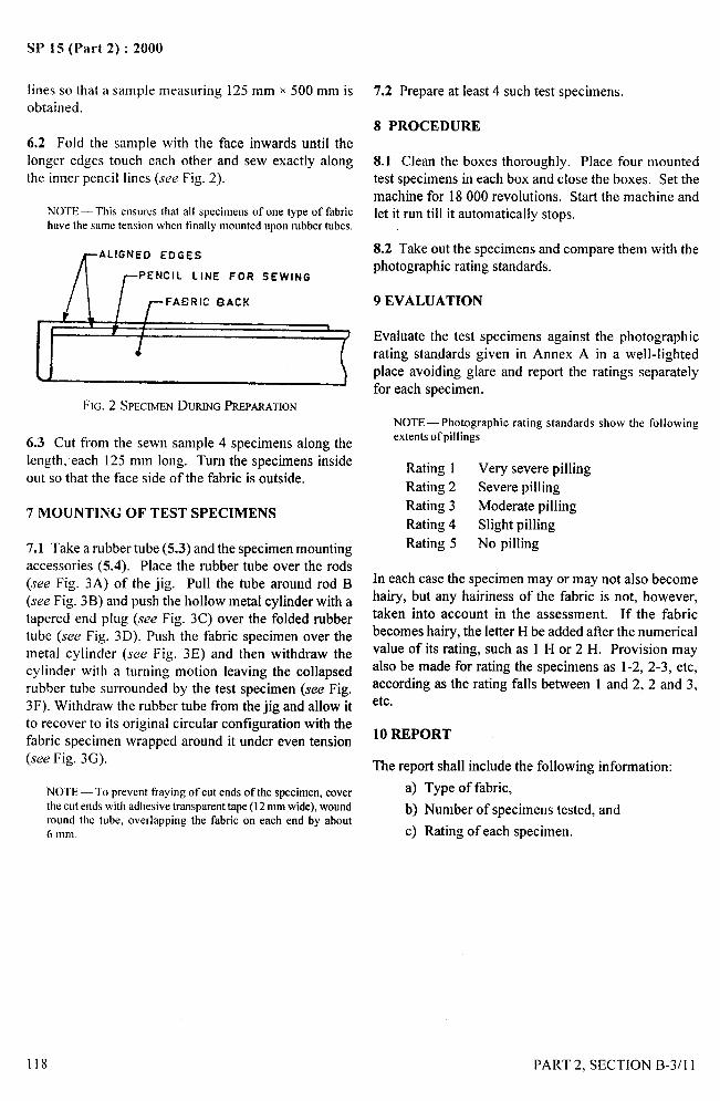
SP 15 (Part 2) :2000
. ---—
lines so that a sample measuring 125 mm x 500 mm is
obtained.
6.2 Fold the sample with the face inwards until thekmgeredges touch each other and sew exactly alongthe inner pencil lines (see Fig. 2).
NOTE —Thiswsores that aIl specimens ofonetype of fabrichave the same tension when finally mounted upon rubber tubes.
[
ALIGNED EDGES
/-P ENCiL LINE FOR SEWING
II / /- FAERIC BACK
FIG. 2 SPECIMENDURINGPREPARATION
6.3 Cut from the sewn sample 4 specimens along thelength, each 125 mm long. Turn the specimens insideout so that the face side of the fabric is outside.
7 MOUNTING OF TEST SPECIMENS
7.1 Take a rubber tube (5.3) and the specimen mountingaccessories (5.4). Place the rubber tube over the rods
(see Fig. 3A) of the jig. Pull the tube around rod B(see Fig. 3B) and push the hollow metal cylinder with atapered end plug (see Fig. 3C) over the folded rubbertube (see Fig. 3D). Push the fabric specimen over themetal cylinder (see Fig. 3E) and then withdraw thecylinder with a turning motion leaving the collapsedrubber tube surrounded by the test specimen (see Fig.3F). Withdraw the rubber tube from the jig and allow itto recover to its original circular configuration with thefabric specimen wrapped around it under even tension(see Fig. 3G).
NOTE — To prevent fraying of cut ends of the specimen, coverthe cut ends with adhesive transparent tape (12 mm wide), woundround the tube, overlapping the fabric on each end by about6 mm.
7.2 Prepare at least 4 such test specimens,
8 PROCEDURE
8.1 Clean the boxes thoroughly. Place four mountedtest specimens in each box and close the boxes. Set themachine for 18000 revolutions. Start the machine andlet it run till it automatically stops.
8.2 Take out the specimens and compare them with thephotographic rating standards.
9 EVALUATION
Evaluate the test specimens against the photographicrating standards given in Annex A in a well-lightedplace avoiding glare and report the ratings separatelyfor each specimen.
NOTE— Photographic rating standards show the followingextents ofpillings
Rating 1 Very severe pilling
Rating 2 Severe pilling
Rating 3 Moderate pilling
Rating 4 Slight pilling
Rating 5 No pilling
In each case the specimen mayor may not also becomehairy, but any hairiness of the fabric is not, however,taken into account in the assessment. If the fabricbecomes hairy, the letter H be added after the numericalvalue of its rating, such as 1 H or 2 H. Provision mayalso be made for rating the specimens as 1-2, 2-3, etc,according as the rating falls between 1 and 2, 2 and 3,etc.
10 REPORT
The report shall include the following information:
a) Type of fabric,
b) Number of specirnem tested, and
c) Rating of each specimen.
118
,’
PART 2, SECTION B-3/l 1

SP 15 (Part 2) :2000.
i
RUBBER TUBE
,’%%%z~~
A i!!!!n
STEEL BASE PLATE
. — - ~_ -_z ----- ------- ---- — —-—- —.-— —“ _____ ----- --- A
----- ----- -- z
“B
160 +6 STEEL RODSJ
3A Jig With Rubber Tube
RuBBER TUBE
B- “ ~ q
430 .*28
+
*
160 4
30 Rubber Tubepulled Round Rod B
3C Metal Cylinder With Solid Metal
SPECIMEN
B
RUBBER TUBE
t
1-
+PECIMEN
\ I-RUBBER TUEE
METALCYLINDER
!i!sl
RuBBER TUBE
0 - .\* \
I I1*I\
*- -“*
3D Metat CylinderP[aced OverRubber Tube
35 Specimen Orawn 3F Metal Cylinder 3G Mounted Specimen AfterOver The Metal Withdrawn,Leaving Withdrawal From JigCylinder Specimen Outside
Folded Rubber Tube
All dimensionsin millimetres.
FIG. 3 SPECIMENMOUNTINGPROCEDURE
k..,.
PART 2, SECTION B-3/l I
I
119
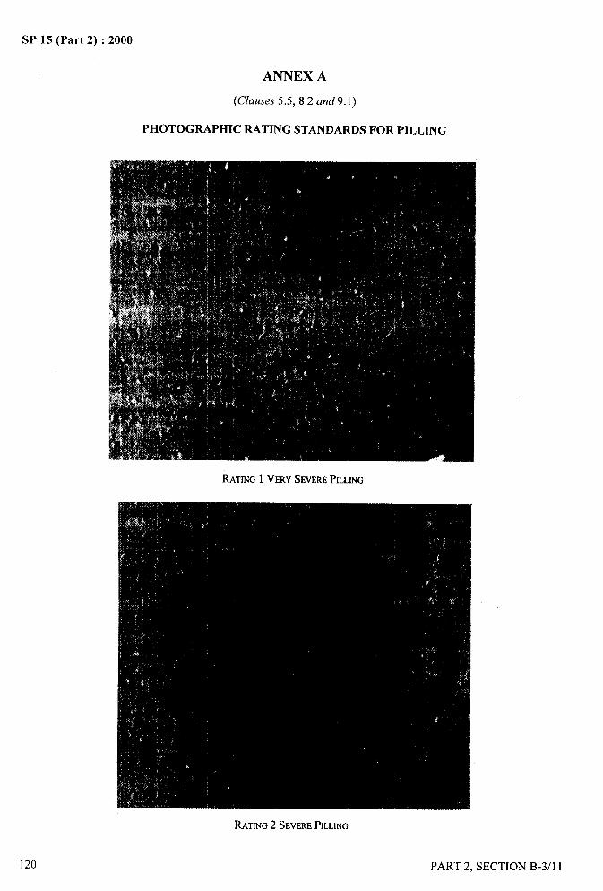
SP 15 (Part 2) :2000
ANNEX A
(Clauses 5.5,8.2 and9.1)
PHOTOGRAPHIC RATING STANDARDS FOR PILLING
_ .—4
RATING1 VERYSEVEREPILLING
.. . .
Iit
‘1‘“1RATING2 SEVEREPILLING
120
/
PART 2, SECTION B-3/l 1
II
II
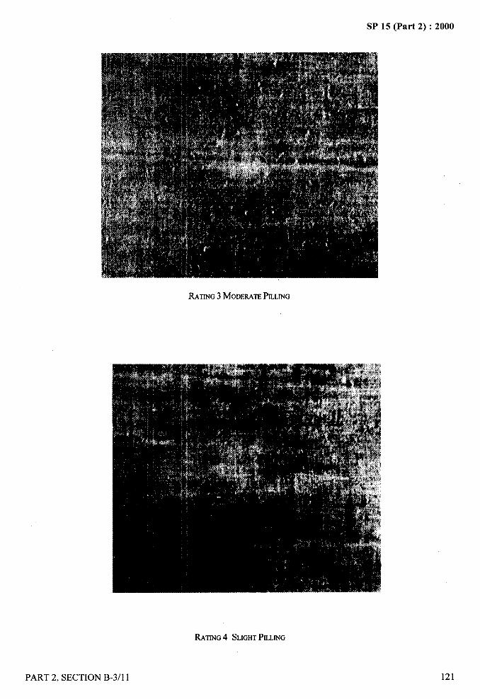
SP 15 (Part 2) :2000
RATING3 MODERATEPILLING
RATING4 SLIGHTPILLING
PART 2, SECTION B-3/l 1
—...-.
,.:..-
y,,..
,i$
121
II,;
,
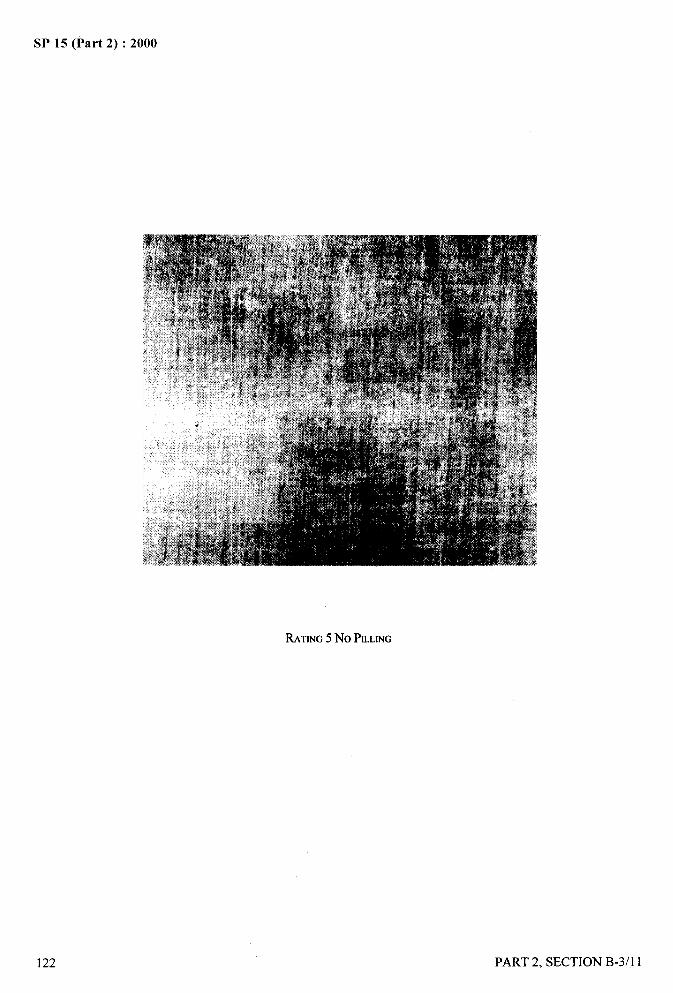
SP 15 (Part 2) :2000
RATING5 No PILLING
122
.—
j%.!
PART 2, SECTION B-3/l 1
\#<
. . . ..-
SP 15 (Part 2) :2000
DETERMINATION OF
AIR PERMEABILITY OF FABRICS
(Source: IS 11056:1984)
Air permeability is an important feature for fabrics used for special technical purposes such as filter cloths, felts,impregnated fabrics, membranes, parachutes, packing materials, etc. Air permeability may also be used for clothingfabric to indicate their breathability.
1 SCOPE
It prescribes a method for measuring the permeability offabrics to air and is applicable to industrial fabrics thatare permeable to air. However, the method is not suitablefor parachute fabrics.
2 PRINCIPLE
The method is based on the measurement of the rate offlow of air through a given area of fabric by a givenpressure drop across the fabric.
3 TERMINOLOGY
For the purpose of this standard, air permeability shallmean the volume (cm3) of air passing through 1 cmz of
fabric per second at a pressure difference of 1 cm head ofwater.
4 SAMPLING
Samples drawn in accordance with the procedure laiddown in material specification for the fabric or as agreeedto between the parties concerned shall be held to berepresentative of the lot.
5 ATMOSPHERIC CONDITIONS FORCONDITIONING AND TESTING
Prior to test, the samples shall be conditioned to moistureequilibrium in the standard atmosphere of 65 +2 percentrelative humidity and 27 + 2°C temperature from dry side
as laid down in IS 6359:1971 (see S6ction B-l/l). Thetest shall be carried out in the standard atmosphere.
6 APPARATUS
6.1 The apparatus shall consist of the followingarrangements:
a) Means for drawing or forcing air through thefabric of known area.
PART 2, SECTION B-3/12
b)
c)
d)
e)
f)
Circular orifice of definite known area.
Provision to hold the fabric so that there is no
peripheral leakage of air.
Means for adjusting the pressure drop acrossthe fabric to a known amount.
Means for measuring the rate of flow of airthrough the fabric.
Means for checking the calibration of air flowmeter (see Annex A).
6.1.1 It is desirable that the apparatus shall be capable
of testing large pieces of fabrics without cutting.
7 PROCEDURE
7.1 Take the conditioned specimen and mount a portion
between the clamp and circular orifice with sufficienttension to eliminate wrinkles, if any, taking care to seethat the fabric is not distorted in its own plane.
7.2 Start the suc~on f& or other means to force the air
through the fabric and adjust the rate of flow of air tillpressure drop of one centimetre water head across thefabric is indicated.
7.3 Note the rate of flow of air in cm3/s.
7.4 Repeat the test at other different places. In all, atleast 10 tests shall be carried out.
8 CALCULATION
Calculate the rate of flow of air per cmz of fabric incm3/s by the following formula:
R=:
where
R = rate of flow of airlcmz of fabric in cm3/s,
r= mean rate of flow of air in cm3/s, and
A= area cmz of fabric under test in cmz.
123
4
/
4-
SP 15 (Part 2) :2000- ——
9 REPORT
The report shall include the following information:
a) Type of fabric tested;
b) Name of the instrument used;
c) Number of tests recommended;
d) Average air permeability value (cm’/cm’/s); and
e) C. V. percent.
ANNEX A
[Clause 6.1 (f)]
CALIBRATION OF AIR FLOW INSTRUMENTS
A-1 GENERAL
A-1. 1 Air flow instruments are very sensitive instrumentsand therefore require delicate and careful handling toavoid malfimctioning. Malfunctioning of the instrumentscan be caused by air leakage, physical damage to thenozzle or test plate, wornout condition of the gasket orover flow of liquid in the manometer, etc.
+2 CALIBRATION
A-2.1 Different instruments are provided with differentmeans and accessories for the calibration and checkingof the air flow instruments, like steel plates with holes togive pre-determined airflow values, capilhuy resistanceshaving pre-determined air flow values to be used in
conjunction with roto meters, set of nozzles and plates,etc. Before using the instruments, check and calibrate
with the help of the calibration accessories provided withthe instruments as per the instructions given in theInstrument Manual.
124
/
PART 2, SECTION B-3/12
.. -
f
SP 15 (Part 2) :2000
DETERMINATION OF
STIFFNESS OF FABRICS — CANTILEVER TEST
(fkwce: IS 6490:1971)
1 SCOPE
1.1 It prescribes a method for determination of stiffnessof fabrics made from any textile fibre or a blend of twoor more textile fibres.
1.2 This method of testis not suitable for fabrics whichare very limp or which curl or twist bad] y when cut intosmall pieces; in general, this method is more suitable fortesting woven fabrics than for testing knitted ones.
2 PRINCIPLE
The principle employed is to measure a particular length
of the fabric specimen of specified dimensions whichwhen used as a cantilever bends to a constant angle underits own weight.
3 TERMINOLOGY
For the purpose of this test method, the followingdefinitions shall be used.
3.1 Stiffness
Resistance of fabric to bending.
3.2 Flexural Rigidity
Ratio of the small change in bending moment per unitwidth of the material to the corresponding smaIl changein the curvature, expressed in milligram centimetres(mg-cm).
3.2.1 This quantity is a measure of the resistance ofcloth to bending by external forces. It is related to thequality of stiffness that is appreciated when a fabric ishandled; that is, the cloth having a high flexural rigiditytends to feel stiff.
3.3 Bending Length
Cube root of the ratio of the flexural rigidity (milligram-centimetres) to the weight per unit area (miligram persquare centimetre) of the fabric. Bending length equalshalf the length of rectangular strip of fabric that will bendunder its own weight to an angle of 41.5°. It is alsoequal to the length of a rectangular strip of materials
PART 2, SECTION B-3/13
that will bend under its own weight to an angle of 7.10.It is expressed in centimetres.
3.3.1 This quantity is one of the factor that determinesthe manner in which fabric drapes. It is related to thequality of the stiffness that is appreciated by visualexamination of the draped material, that is, the clothhaving high bending length tends to drape stiffly.
4 SAMPLING
Sample drawn in accordance with the procedure laiddown in relevant specification for the material or asagreed to between the buyer and the seller shall berepresentative of the lot.
5 PREPARATION OF TEST SPECIMENS
5.1 From the samples, as selected in 4.1 cut rectangularwarpway and we ftway test specimens of25 mm x 200 mm size preferably with the help of atemplate from different portions of the sample under test.The lengthwise direction of specimens shall be parallelto the warp or weft direction for which the stiffhess is tobe determined. Specimens cut in each direction shall bescattered as far as possible so that no two warpwayspecimens contain the same set of warp yarns and notwo we ftway specimens contain the same set of weftyams. Avoid selvedges (within 10 cm), end portions,creased or folded places. The specimens shall be handledas little as possible.
6 ATMOSPHERIC CONDITIONS FORCONDITIONING AND TESTING
6.1 Prior to test, the fabrics shall be conditioned tomoisture equilibrium and tested in standard atmosphericconditions of 65*2 percent RH and 27*2°Ctemperature as laid down in IS 6359:1971 ‘Methods forconditioning of textiles’ given in Section B-1/1.
6.2 The test shall be carried out in standard atmosphere(see 6.1).
7 APPARATUS
7.1 Stiffness Tester
Having the following parts:
125
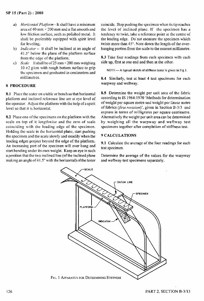
SP 15 (Part 2) :2000
a) Horizontal Platform - Itshall have a minimumarea of 40 mm x 200 mm and a flat smooth andlow friction surface, such as polished metal. Itshall be preferably equipped with spirit levelfor leveling.
b) Indicator – It shall be inclined at an angle of41.5° below the plane of the platform surfacefrom the edge of the platform.
c) Scale – It shall be of 25 mm x 200 mm weighing10 +2 g/cm with rough bottom surface to grip
the specimen and graduated in centimetres andmillimetres.
8 PROCEDURE
8.1 Place the tester on a table or bench so that horizontalplatform and inclined reference line are at eye level of
the operator. Adjust the platform with the help of a spiritlevel so that it is horizontal.
8.2 Place one of the specimens on the platform with thescale on top of it lengthwise and the zero of scalecoinciding with the leading edge of the specimen.Holding the scale in the horizontal plane, start pushingthe specimen and the scale slowly and steadily when theleading edges project beyond the edge of the platform.An increasing part of the specimen will over hang and
start bending under its own weight. Keep an eye in sucha position that the two inclined line (of the inclined planemaking an angleof41.5° with the horizontal) of the tester
coincide. Stop pushing the specimen when its tip reachesthe level of inclined plane. If the specimen has atendency to twist, take a reference point at the centre ofthe leading edge. Do’ not measure the specimen whichtwists more than 45°. Note down the length of the over-hanging portion from the scale to the nearest millimetre.
8.3 Take four readings from each specimen with eachside up, first at one end and then at the other.
NOTE— A typical sketch of stiffness tester is given in Fig, 1.
8.4 Similarly, test at least 4 test specimens for eachwarpway and we ftway.
8.5 Determine the weight per unit area of the fabricaccording to IS 1964:1970 ‘Methods for determinationof weight per square metre and weight per linear metreof fabrics (first revision)’, given in Section B-3/3 andexpress in terms of milligrams per square centimetre.Alternatively the weight per unit area can be determinedby weighing all the warpway and we ftway testspecimens together after completion of stiffness test.
9 CALCULATIONS
9.1 Calculate the average of the four readings for eachtest specimen.
Determine the average of the values for the warpwayand wetlway test specimens separately.
j,,,.,
126 PART 2, SECTION B-3/l 3
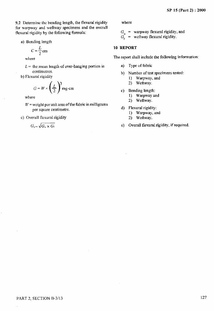
*-
9.2 Determine the bending length, the flexural rigidity
for warpway and we ftway specimens and the overallflexural rigidity by the following formula
a) Bending length
C=*cm
where
L = the mean length of over-hanging portion incentimetres.
b) Flexural rigidity
()~3G=WX
2mg-cm
where
W= weight per unit area of the fabric in milligramsper square centimetre.
c) Overall flexural rigidity
Go=J=
PART 2, SECTION B-3/l 3
-—SP 15 (Part 2) :2000
where
GW = warpway flexural rigidity, andG~ = we ftway flexural rigidity.
10 REPORT
The report shall include the following information:
a) Type of fabric
b) Number of test specimens tested:1) Warpway, and2) We ftway.
c) Bending length:1) Warpway and2) We fhvay.
d) Flexural rigidity:1) Warpway, and
2) Wet3way.
e) Overall flexural rigidity, if required.
127
k,>

SP 15 (Part 2) :2000
DETERMINATION OF THERMAL RESISTANCE OF TEXTILE
FABRICS GUARDED HOT-PLATE METHOD
(Source : IS 2702:1965)
The thermal resistance of a fabric is one of the important factors which influence the effectiveness of the fabric inkeeping the body comfortable. This factor includes the thermal conductivity of the fabric.
1 SCOPE
1.1 It prescribes a method for determining the thermalresistance of textile f~brics.
1.2 This method is applicable to all types of textilefabrics including blankets shawls, etc, irrespective oftheir composition (that is irrespective of whether thefabric is made of wool, silk, nylon or a blend of two ormore textile fibres) and their construction (that is,irrespective of whether the material is a woven fabric, aknitted fabric or a felted material).
2 TERMINOLOGY
2.1 Thermal Resistance
The resistance offered by the fabric to the flow of heatwhen its two faces are at different temperatures, asdenoted by the ratio of the temperature difference to therate of flow of heat per unit area, the flow being normalto the surfaces.
NOTE— Since surface temperatures of fabrics are difficult tomeasure precisely, the temperature difference between the hot-plate on which the fabric is put during test and that of air 20mm above the other surface of the fabric will be taken to assessthe thermal resistance.
2.2 Tog
The unit of thermal resistance. This is the resistancethat will maintain a difference of 10 degree between twoparallel isothermal plates with a heat flux of one wattper square decimetre.
NOTESI By adoptingthis unit the thermal resistanceof anyfabriccouldbeconvenient y described by a range of small integers (1to 10). Forexample, a Iight summer suiting has a thermal resistance of 1togand 10togs represent the thickest clothing that could be worn.2 Still air has a thermal resistance of 0.4 togs approximately.
3 SAMPLING
Sample to determine conformity of a lot to this standardshall be selected so as to be representative of the lot.
128
4 APPARATUS
4.1 The apparatus shall consist ofa) hot-plate assembly,b) heaters, andc) devices for measuring the surface temperature
of hot-plates.
4.1.1 Hot-Plate Assembly
The hot-plate assembly (see Fig. 1) shall consist of thetest plate, guard ring plate and the bottom plate whichis intended to prevent a downward loss of heat from theother two plates. All the plates shall be made fi-om thin(1.5 mm to 2 mm thick) sheets of highly conductivemetal like copper. The surface of the metal shall befinished to a true plane and lacquered to give a highemissivity. Each of these shall be electrically heatedand maintained at a constant temperature by separateheating grids.
4.1.1.1 The hot-plate assembly shall be housed in anair-tight wooden box one metre cube provided with:
a)
b)
c)
d)
e)
thermostatic arrangement to maintain a constant
temperature with an accuracy of * O.5°Cat about 8 to 10°C below the bottom platetemperature,
arrangements to maintain a constant humiditywithin the box and to measure it,
arrangements to maintain the velocity of airat 1 m/s,
suitable means to direct the air current so as toimpinge on the specimen at an angle of 45°,
and
thermocouples suspended inside the box so thatthe measuring junction is exposed to the air at20 mm above the test specimen to measure thetemperature of the ambient air inside the box.
4.1.2 Heaters
Each of the heating grids used for maintaining the platesat constant temperature shall be provided with separate
PART 2, SECTION B-3/14
/
SP 15 (Part 2) :2000
-.. .—
%
~
c~ kB8i D
. ---- —-—
I
u uL
c H H;
T7 300 SQ
T
150 SQ
250 SQ
SCREWS
PLATE
LEATING
25
TBLOCK
E TS
/’—
250 SQ ~
ELECTRIC HEATING GRID\ BOTTOM PLATE
B - Bottom-plate therrno-wrpleC,D – Test-platetherrno-couplesEE – Test-plate heater-terminalsFF – Differential-couple across the test plate and guard ring plateCC - Guard-ring plate heater terminalsHH – Bottom-plateheaterterminalsA – Guard-ringplate therrno-coupleSQ – Square dimension
All dimensionsin millimetres.
FIG. 1 HOT PLATEASSEMBLY
i
/
PART 2, SECTION B-3/14 129
,, #i
SP 15 (Part 2) :2000
electric circuit with a control to adjust the current and clamps, keep the test specimen in contact with the testmeters to measure the current and the voltage to an plate and guard ring plate at zero tension and close theaccuracy of+ 1 percent. The current maybe alternating wooden box.or direct. The heating grids shall be insulated from theplates by means of thin sheets of mica. NOTE— At low temperatures when testing takes more time pre-
heatingmay be done, ifnecessary.
4.1.3 Devices fop measuring Surjace Temperature6.4 Read the temperature of the test plate, guard ring
The surface temperature of the hot-plates shall beplate and the bottom plate at half-hour intervals until
measured by fine wire thermocouples. The differencethe three temperatures show identical and constant
in temperature between the test plate and the guard ringvalues (see Note) and the differential thermocouple
plate shall be measured by a differential thermocouple.gives zero reading. Take again at least four morereadings at half-hour intervals. Note down this
NOTE— Calibrated thermocouples such as copper-constantan constant temperature (Tl ). Note down the current in
or copper-advance may be used. amperes (C) and the voltage (V) as read from theammeter and voltmeter respectively, of the heater
4.1.3.1 Potentiometer having high sensitivity of at least circuit of the test plate. By means of the thermocouple
5 microvolt shall be used for measuring thermal kept at 20 mm above the test specimens, measure the
electromotive force and other voltages. The wattage of ambient air temperature (Tz) inside the box.
the central heater may be measured.NOTE- If the difference in temperature between the successive
5 PREPARATION OF TEST SPECIMENreadings doesnot exceed 0.1“C,the temperature shall be held to be‘Xnr.stant.
5.1 Cut out from each piece constituting the test sample 6.5 Calculate, correct to two places of decimals, thea test specimen (see Note) of 300 mm x 300 mm such thermal resistance in togs of the test specimen as under:that two adjacent sides are parallel to the direction ofwarp and weft respectively. Cut out at least 3 more test Thermal resistance, in togs, of the test specimen =specimens so that the total number of test specimens isat least 4. (T[-7’2)X 10
ax CxvxloNOTE— In case the sample is a woven fabric cut out the test ~herespecimen from a distance of at least 150 mm away from theselvedges.
a = area of the test plate in dmz;
6 PROCEDURE T, = temperature of test plate in “C;
6.1 Switch on the electrical circuit of the three heatersTz = temperature of ambient air inside the box
in ‘c;and adjust the current so as to maintain the temperatureof the three plates at 33°C to 36”C. C = current, in amperes, to maintain the test plate
at T}”C; and
NOTES V = voltage required to maintain the test plate
1 All the plates are to be kept at the same temperatureso that all the at TIOC.
electrical energy suppliedto the test plate is lost as heat energyonlyin direction normal to the fabric under test. 6.6 Repeat the test with the remaining test specimens2 In order to simulate the actual condition of sample when in use,the temperature has been prescribed as 33°C to 36°C which is
and calculate the mean of the values. Report it as the
assumed as the tvoical human skin tem~erature. thermal resistance of the fabric in the lot. Report also.,the relative humidity inside the box.
6.2 Adjust the temperature of the air inside the woodenbox to remain at a constant value of 25°C and the air 7 REPORT
circulating inside the box at a velocity of 1 m /s and thehutnidity at a constant value. The report shall include the following information:
6.3 Transfer the test specimen to the test date. If thea) Type of fabrics,
test specimen is pre-heated (see Note), this transfer b) Thermal resistance togs, and
should be effected very quickly. By means of suitable c) Relative humidity inside the base.
/
130 PART 2, SECTION B-3/14
SP 15 (Part 2) :2000
METHOD FOR ASSESSMENT OF FABRIC DRAPE
(&WC~ : IS 8357:1977)
Drape is one of the subjective performance characteristics of fabric that contributes to asthetic appeal; it is a complexproperty involving bending and shearing deformations. The present method provides objective estimation of theextent to which a fabric drapes; draping quality is expressed as drape coefficient which theoretically varies betweenO and 100.
Drape measurements can be employed for study of the effects of fabric geometry, chemical processing treatmentsand finishes for woven and knitted fabrics, certain qualities of non-wovens like leather for apparel. Drape coefficientcan also be used as an index for control of batches in production.
1 SCOPE
It prescribes a method for assessment of drape of fabrics b)and is applicable to all fabrics intended for end uses inwhich drape is important.
2 PRINCIPLEc)
A circular fabric specimen is sandwiched between twohorizontal discs of smaller diameter, and the d)
unsupported annular ring of fabric is allowed to hangdown under the action of gravity. A planar projection e)
of the contour of the draped specimen is recorded on alight-sensitive paper. The drape pattern obtained is
cut along the outline and its area determinedgravimetrically. The drape coefficient is calculated asthe ratio of the projected area of the drape specimen toits theoretical maximum.
3 TERMINOLOGY
For the purpose of this test method the following
definitions shall apply.
3.1 Fabric Drape
The extent to which a fabric will deform when it is
allowed to hang under its own weight.
3.2 Drape Co-efficient
The area covered by the shadow of the draped specimen
expressed as a percentage of the area of the annular ring
of fabric.
4 APPARATUS
4;1 Drape Tester
Consisting of:
a) a pair of horizontal discs of 12.3 cm diameter
between which the specimen is held; the lower
disc has a central pin for positioning on a holder.
an actinic source of light placed directly above
the centre of the discs with suitable attachment
to give a parallel beam of light.
arrangement to place a sheet of ammoniaprocess paper horizontally below the draped
. specimen (see also 4.3).timer and other devices to aid exposure forprescribed time.an enclosed box for developing the drapepattern in ammonia vapour.
NOTE— An outling of a suitable apparatus developed byBombay Textile Research Association, Bombay working on theabove principles is given in Annex A, Mention of the name of aspecific (or proprietary) instrument is not intended to promoteor give preference to the use of that instrument over those notmentioned.
4.2 Circular Template
A metal template of 250 mm diameter and with a centralhole for marking and cutting specimens for drape test.
4.3 Ammonia Process Paper
NOTES
1 In case ammonia process paper is not availbale, a good qualitydrawing paper may be used, and the outline of the drape patternmay be carefully traced by hand.
2 For better results photographic grade of ammonia paper maybeused.
4.4 Balance
Capable of determining mass to the accuracy of 0.01 g.
5 ATMOSPHERIC CONDITIONS FOR
CONDITIONING AND TESTING
5.1 The test specimens shall be conditioned to mositureequilibrium in standard atmosphere of 65+2 percentRH and 27* 2°C before testing (see IS 6359:1971
PART 2, SECTION B-3/15
SP 15 (Part 2) :2000
‘Method for conditioning of textiles’ given in SectionB-1 /1 )and the tests shall be carried out in the standardatmosphere.
6 PREPARATION OF TEST SPECIMENS
6.1 Marking and Cutting
Place the fabric free from creases and wrinkles on a flathorizontal surface and by means of the template (4.2)
trace the outline, mark the centre of each, and cut thespecimens. Ensure that the specimens representadequately the fabric under test and exclude the areaswithin 5 cm of the selvedges and those with wrinkles or
sharp folds.
7 PROCEDURE
7.1 Place the drape tester firmly on a level table. Switchon the light (The mercury vapour lamp when lightedattains full brightness after a few minutes.).
7.2 Remove the specimen holder from the bayonetsocket and place a cut fabric specimen between the plates.Hold the stub of the specimen holder assembly andbriskly move the holder with the specimen up and downten times, each time resting on the table for a moment(This is to allow the fabric to orient itself freely anddrape into natural folds.).
7.3 Place a square of ammonia process paper on thebase of the instrument and lay it flat.
7.4 Insert the stub of the specimen holder (with thespecimen) in the socket on the threaded bolt. Pressupwards and turn counter clock-wise to lock the holderin position.
7.5 Looking along the level of the base-board, adjustthe height of the drooping edge of the drape specimens,so that the lowermost edge is just above the paper withouttouching it.
7.6 Adjust the setting knob of the timer for the required
time of exposure.
NOTE — The optimum exposure time depends on the quality ofthe paper used, and will have to be determined experimentally.
7.7 At the end of the exposure time, remove theammonia process paper and place the same in thedeveloping box containing a few millilitres of strong
ammonia solution. Remove the paper when the latent isdeveloped.
7.8 Condition the paper to moisture equilibrium instandard atmosphere. Cut out the drape pattern with a
pair of scissors and determine its mass in gram correctto two decimal places.
#,
.— -—
7.9 Determine the mass per unit area of the paper usedby cutting a known area of the original paper andweighing.
7.10 Reverse the specimen and obtain the drape patternwith the other surface upwards.
7.11 Number of Tests
Test at least four specimens making a total of eightmeasurements.
8 CALCULATIONS
8.1 Calculate the drape co-efficient for each test asunder:
w
Drape co-efficient (F%) _ w a ~ ~00—where A–a
W = mass per unit area of the paper,
w = mass of the drape pattern,
a = area of circle of 12.5 cm diameter = 122.8 cmz,
and
A = Area of circle of 25 cm diameter=491. lcmz.)ii.,
OR..
By substituting the values of ‘a’ and ‘A’:
~– 122.8Drape co-efficient = L x 100
368.3
8.2 Calculate the arithmetic mean of alJ the individualtest values and round it off to two significant figures.
9 REPORT
9.0 The report shall comprise the following information:
a)
b)
c)
d)
Type of fabric;
Name of the instrument used;
Number of specimens tested; and
Mean drape co-efficient.
132
/
PART 2, SECTION B-3/l 5
I;,
I
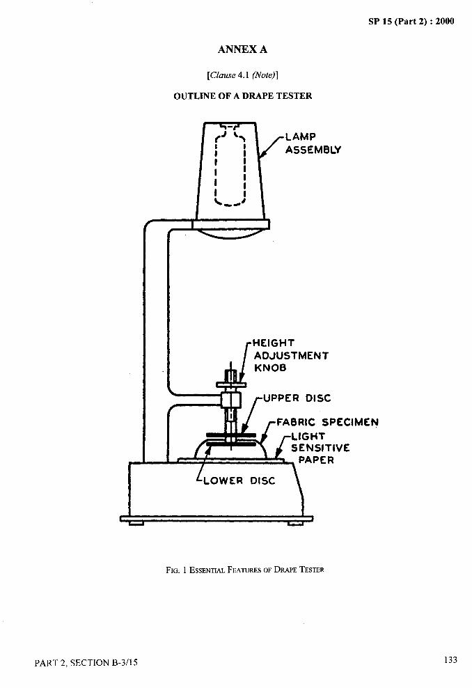
SP 15 (Part 2) :2000. .. .. —-
ANNEX A
[Clause 4.1 (Note)]
OUTLINE OF A DRAPE TESTER
LAMPASSEM6LY
::,II1L: -4
/I 1
ADJUSTMENT
UPPER DISC
FA8RIC SPECIMEN
?
FIG. 1 ESSENTTALFEATURESOFDRAPETESTER
PART 2, SECTION B-3/l 5 133
SP 15 (Part 2) :2000
DETERMINATION OF ABRASION RESISTANCE OF
TEXTILE FABRICS
(t%urce: IS 12673:1989)
Several factors such as bending, stretching, tearing, abrasion, laundering and cleaning contribute to the wearperformance or durability of fabrics. Abrasion which is just one aspect of wear is caused by the rubbing of thecomponent fibres and yams of the fabric.
The nature of abrasion met within the actual use of a fabric is of different type and severity. Therefore, it is virtually
impossible to imitate the abrasion exactly in any one labroatory test. In addition, the conditions of abrasion operatingon different types of fabrics are so different that a single type of abrasion test to assess the relative durability of eachis not feasible.
The type of abrasion test suitable for a given fabric depends on the assessment of the relative importance of factorsthat can be anticipated as being more involved during service (such as, rubbing or flexing ).
The approach followed here is, therefore, to subject a fabric to such type of abrasion and determine whether one
fabric will probably outlast in similar and specified end use. For instance, the durability of a newly developed fabriccan be compared with an already accepted fabric.
Laboratory assessment of abrasion resistance of a fabric can be affected by many variable factors, namely, natureof abradant, tension on test specimens, pressure between abradant and test-specimens, direction and speed of theabradant motion, removal of lint and other debris, and judgement of operator when a visual end point is used.Variation in these abrasion conditions can easily cause a larger deviation in test results than that due to the difference
among samples, thus invalidating the results of an entire test. Hence, the abrasion resistance results obtained bydifferent operators and in different laboratories may show a high degree of variability and the precision of thismethod is uncertain. Considerable caution is, therefore, required in interpreting the results of abrasion tests whichcannot be relied upon for comparing fabrics of widely different fibre compositions or construction.
1 SCOPE
1.1 It prescribes methods for the determination of
resistance of textile fabrics to plane abrasion (flat
abrasion) and flex abrasion.
1.2 Except for floor covering fabrics, the methods
prescribed are applicable to all textile fabrics, irrespective
of their composition (that is whether the fabric is made
of cotton, wool, silk, jute or man-made fibres or a blend
of two or more such fibres) and history (that is, the
manufacturing processes involved and the finishing
treatments).
1.3 In the case of narrow fabrics, only flex abrasion
resistance shall be determined.
2 TERMINOLOGY
For the purpose of this test method the following
definitions shall apply.
134
2.1 Abrasion
The wearing away of any part of a material by rubbingagainst another surface.
2.2 Plane Abrasion
The abrasion of the material from flat area.
2.3 Flex Abrasion
Rubbing accompanied by flexing and bending.
2.4 Edge Abrasion
Abrasion similar to the one occurring at collars and folds.
3 SAMPLING
Sample from the lot shall be drawn so as to berepresentative of the lot. Sample drawn in accordancewith the relevant material specification or as agreed to
PART 2, SECTION B-3/l 6
—..-
,,
4-
--- —.
SP 15 (Part 2) :2000
between the buyer and the seller shall be held to berepresentative of the lot. In the absence of above, theprocedure given in IS 3919:1966 (see Section A-1/2)may be followed.
4 ATMOSPHERIC CONDITIONS FORCONDITIONING AND TESTING
4.1 Prior to test, the fabric shall be conditioned to
moisture equilibrium from the dry side, in the standardatmosphere of 65+2 percent relative humidity and27+ 2°C temperature as prescribed in IS 6359:1971
{ (see Section B-l/l).
4.2 The test shall be carried out under standardatmospheric conditions.
5 CHOICE OF METHOD
Any one of the methods maybe used for determinationof abrasion resistance of fabric depending upon thematerial specification or agreement between the parties,about the type of the instruments, facilities available andcharacter of testing desired, such as, plane abrasion orflex abrasion.
6 DETERMINATION OF PLANE ABRASIONRESISTANCE
6.1 General
Although plane abrasion of fabric surface does notnecessarily cover all aspects of strains which areimportant in determining service life, there are occasionswhen such a test gives usefid information. Plane abrasionresistance shall be determined using one of the twocommercially available testers (see Annex A and B) byMethod 1 and 2.
6.2 Method 1
6.2.1 Principle
Circular specimens of fabric are abraded under knownpressure on an apparatus giving a motion which is theresultant of two simple harmonic motions at right anglesto each other. The resistance to abrasion is estimatedby breakage of threads or by loss in mass of thespecimens.
6.2.2 Apparatu,r
The abrasion tester is described in Annex A.
.;NOTE— The apparatus specified in this test was designed to ,9_.. —.,
,!give a controlled amount of abrasion between fabric surfaces atcomparatively low pressure in continuously changing directions. .!
6.2.3 Test Specimen Preparation
Cut or punch four circular specimens of 38 mm diameter,~
for the breakage method of assessment and eight
specimens for the loss in mass method of assessment.
6.2.4 Test Procedure
6.2.4.1 Mount test specimen on a 38 mm diametercircular piece of foam placed in the specimen holder.Keep the spec,imen under tension by pressing the holderagainst the brass plate provided on the base of theapparatus and screw it up tightly.
6.2.4.2 Mount a new piece of abradant on each of thefour tables with a piece of felt, as specified, beneath theabradant. Keep the abradant under tension by placing aweight on its surface before tightening up the retainingtiame. Replace the abradant at the start of each test andafier 50000 rubs, if the test is continued beyond thisnumber.
6.2.4.3 Clamp the specimen holders on the moving plateunder the desired load and switch on the machine.
NOTE—Normally a total load of 125 g/cm2is used but a lowerload of 30 g/cm2may be used if agreed to between the buyer andthe seller.
6.2.5 Choosing of the End-Point
Estimate the resistance to abrasion either by abradingtill two threads break or by loss in mass of the specimens,as has been agreed to between the buyer and the seller.
6.2.5.2 Breakage of threads
Continue abrading the specimens until two threads arebroken, rounding each reading to the nearest 1000 rubs.Record the number of rubs required before breakageoccurs. In some cases, removal of surface nap or otherstate is a more appropriate end-point and this should beused, if agreed to between the buyer and the seller.
6.2.5.3 Average rate of loss in mass
Abrade two specimens to end-point as described in7.1.5.2 to get approximate idea of abrasion resistanceof the sample and further pairs of specimens to threeintermediate stages of approximately 25, 50 and 75percent of the estimated abrasion resistance value
b..,%
PART 2, SECTION B-3/l 6 135
/
SP 15 (Part 2) :2000
choosing the convenient numbers of rubs from the range100,250,500, 1000, 1500,2000,2500,5000,7 500,10000 and 15000. Recondition the specimens and weighto the nearest 1 mg.
6.2.5.4 Plot a graph between the loss in mass and thenumber of rubs. If the points lie in straight line, draw aline and determine the average rate of loss in mass inmg/1 000 rub. If the points lie in curve, draw a curveand read off the loss in mass at three convenient pointschosen from the suitable range.
6.2.6 Report
The report shall include the following information:
a) Description of the material tested;
b) Type of abradant used;
c) Pressure used and the criterion for judging theend point;
d) Average of rubs to specified end points; and
e) If applicable, the average rate of loss in massor the loss in mass at three stages, taken ffom asmooth curve through the points.
6.3 Method 2
6.3.1 Principle
Abrasion resistance of a specimen held in a freed positionand supported by an inflated rubber diaphragm isdetermined by rubbing either unidirectionally ormultidirectionally against a standard abradant.
6.3.2 Apparatus
The abrasion tester is described in Annex B.
6.3.3 Test Specimen Preparation
Cut five circular test specimens of 112 mm in diameter,taking care to avoid specimens from areas containingthe same wales or courses in knitted fabrics or the samewarp and weft yarns in wove fabrics.
6.3.4 Procedure
6.3.4.1 Place the specimen over the rubber diaphragmin a smooth condition and clamp the specimen in placewithout distorting it.
6.3.4.2 Place the abrasive paper or other abradant onthe abradant plate under sufficient tension to be held
136
smooth and in such a position that the contact pin,reaching through a hole in the abradant, is even with the
surface of the abradant.
NOTES
1 Intheabsenceofany specific material specifications zero emerypolishing paper should be used as the abradarrt.
2 If the continuouschangingabradanthead is used, it should benoted that, although the weight of the head is counter balanced,the balance changes during use as the paper passes from the backroll to the front roll.
6.3.4.3 Set the air pressure under the diaphragm and
load on the abradant plate. In the absence of any specific
material specifications, the air pressure should be
0.3 Kg/cm* (4 p.s.i.) and the load on the abradant should
be 454 g. Ensure that the air pressure control and contact
between the inflated specimen and loaded abradant is in
a state of equilibrium before abrasion is started. To
ensure consistent inflation of the diaphragm, inflate to a
higher air pressure (25 percent) and then reduce to testing
pressure.
6.3.4.4 If unidirectional abrasion is desired, disengage
the rotation mechanism of the specimen clamp and,bring
the specimen into the desired direction by turning and
setting the clamp after the diaphragm has been inflated.
6.3.4.5 In the event that multidirectional abrasion is
required, or if no specific indication as to the abrasion
direction is given in the fabric specification, engage the
rotation mechanism of the specimen clamp.
6.3.4.6 Remove pills of matted tibres interfering with
proper contact between specimens and abradant during
the test if they cause a marked vibration of the abradant
plate.
6.3.4.7 If the specimen slips in the clamp or the air
pressure does not remain constant during the test or an
anomalous wear pattern is obtained, discard such
individual measurements and test an additional
specimen.
6.3.5 Choosing of the End-Point
6.3.5.1 Breakage of threads
Abrade the specimen until all fibres in the centre of the
abraded area are worn off so that the diaphragm and the
abradant head come
automatically stops.
.,
into contact and the instrument
PART 2, SECTION B-3/l 6
.—.
.
(’/“~,-,
,’
1’
!
I
1;~1J.
_
SP 15 (Part 2) :2000
6.3.5.2 Removing a predetermined thickness of the 7.3.2 Cut the test specimen 200 mm long and of 32 ormaterial 38 mm width depending on whether the number of yamsl
Abrade the specimen using the electrical depthmicrometer to determine the automatic end-point forremoving a predetermined thickness of the material fromthe specimen as agreed to between the buyer and theseller.
NOTES
1 For testing coated fabrics as well as plastic and rubber sheetingwhich are considered to be worn out, when they becomepermeable to air, a diphragm with a hole in the centre is used. Assoon as sufficient surface material has been worn off from thespecimen to permit air leakage the inflated specimen collapsesand the machine is automatically stopped.
2 Stiff materials and materials with irregular contours such astibre-glass fabrics, stiff pile fabrics, etc, are tested by assemblingspecimens with two diaphragms, the outer diaphragms with alarge hole enabling contact betweenthe specimenandthe abradantplate,
3 Unless the continuous changing abrasion head is used, it isrecommended that the abradant paper be changed atler every300 cycles.
6.3.6 Report
The report shall include the following information:
a) Type of abradant,b) Type of abrasion (unidirectional or
multidirectional), and
c) Number of cycles to reach the end point asdetermined by electrical contact.
7 DETERMINATION OF FLEX ABRASIONRESISTANCE
7.1 Principle
dm of the specimens is below or above 200. Ravel thespecimen to 25 mm in width by removing from each
side approximately the same number of yams. Do not
take two specimens for the warp test from the same warp
ends or any two specimens for the weft test from the
same picks. Take weft specimens at sufficiently wideintervals, whenever possible, to ensure the inclusion of
yam from different cops.
7.4 Procedure
7.4.1 After positioning the bar by means of the yoke
holder, place the specimen between the pressure (upper)
plate and the reciprocating (lower) plate of the apparatusand locate centrally. With the specified folding bar of
folding blade inserted, atler being clamped and loaded
by removal of the yoke holder, distribute the tension
exerted by the bar or blade uniformly over the width of
the specimen and align the long dimension both above
and below the bar parallel to the direction of the
reciprocating motion. Position the specimen with the
fold at the centre (midpoint) of the upper plate, and the
reciprocating plate at the rear of its stroke when the
specimen is clamped.
7.4.2 Load the pressure plate and folding bar or blade
as required by the material specification. In the absence
of the material specification, it is recommended that bar
load sufficient to produce rupture in excess of at least
100 cycles and preferably 300 cycles be used, in
combination with the lowest head load (pressure)
(see Note) sufficient to prevent vibration of the upper
plate at the start of the test. A ratio of bar to head loads
of 4:1 is recommended.
A specimen of the fabric is subjected to unidirectionalreciprocal folding and rubbing over a bar having
NOTE— A low level of load is required to prevent ripping ofthe fabric during testing. This ripping is caused by a high degree
specified characteristics under known conditions of of &lction between the fabric and the bar when abnorarnallv highpressure and tension to evaluate the flex abrasion loads are applied and results in insutlicient relative rnoti&
resistance. between the bar and the fabric specimen under test.
7.2 Description of Apparatus 7.4.3 Check the bar alignment after the first 25 cycles
by noting -whether the bar has shified laterally to either
A tester as specified in the Annex C shall be used. side of its normal rest position. If such shifting occurs,
discard the specimen and make the proper adjustment.
7.3 Test Specimen Preparation7.4.4 Remove the pills of matted fibre debris interfering
7.3.1 Unless and otherwise specified by a material with proper contact between the specimen and the folding
specification or by an agreement between the bar or folding blade during the test if they cause a marl&d
purchaser and the seller, five test specimens shall be vibration of the pressure plate or other wise interfere with
tested. proper abrasion. The pills should preferably be removed
. ....,.
PART 2. SECTION B-3/l 6 137
I I
I1’I
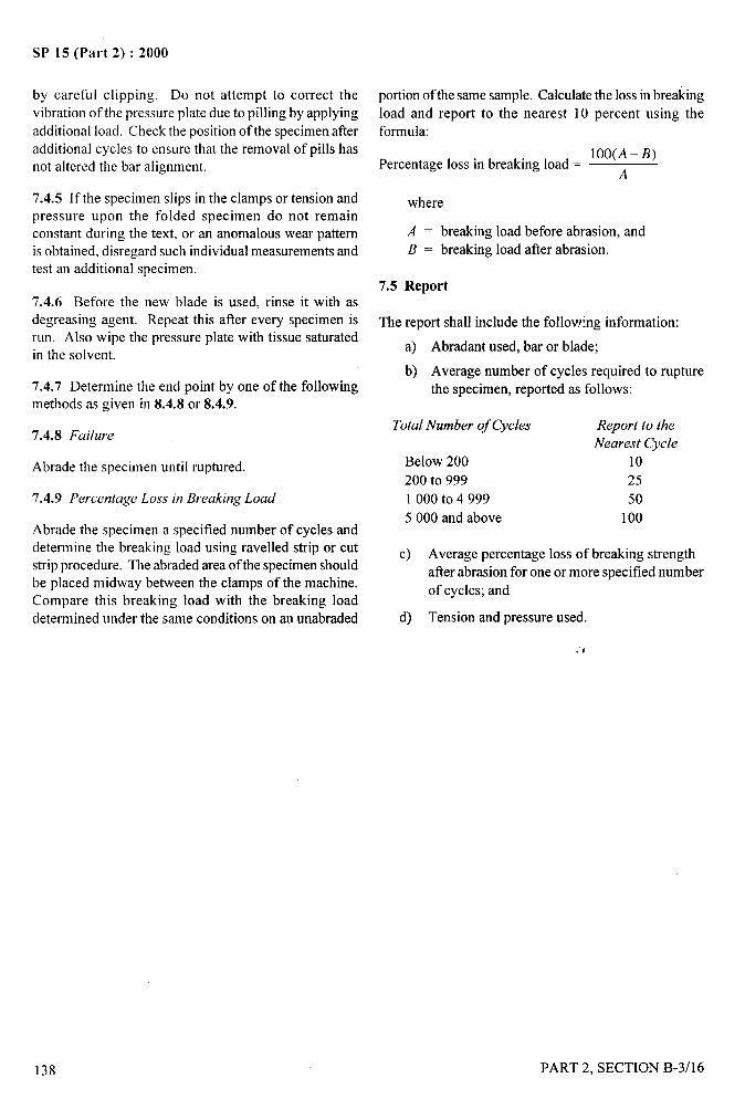
, 4.
.—
SP 15 (Part 2) :2000
by careful clipping. Do not attempt to correct the portion of the same sample. Calculate the loss in breaking
vibration of the pressure plate due to pilling by applying load and report to the nearest 10 percent using the
additional load. Check the position of the specimen after formula:additional cycles to ensure that the removal of pills has 1OO(A-B)not altered the bar alignment. Percentage loss in breaking load= A
7.4.5 If the specimen slips in the clamps or tension andpressure upon the folded specimen do not remainconstant during the text, or an anomalous wear patternis obtained, disregard such individual measurements andtest an additional specimen.
7.4.6 Before the new blade is used, rinse it with as
decreasing agent. Repeat this after every specimen isrun. Also wipe the pressure plate with tissue saturatedin the solvent.
7.4.7 Determine the end point by one of the followingmethods as given in 8.4.8 or 8.4.9.
7.4.8 Failure
Abrade the specimen until ruptured.
7’.4.9 Percentage Loss in Breaking Load
Abrade the specimen a specified number of cycles and
determine the breaking load using ravened strip or cutstrip procedure. The abraded area of the specimen shouldbe placed midway between the clamps of the machine.Compare this breaking load with the breaking load
determined under the same conditions on an unabraded
where
A = breaking load before abrasion, and
B = breaking load after abrasion.
7.5 Report
The report shall include the following information:
a) Abradant used, bar or blade;
b) Average number of cycles required to rupture
the specimen, reported as follows:
Total Number of Cycles Report to the
Nearest Cycle
Below 200 10
200 to 999 25
1 000to4999 50
5000 and above 100
c) Average percentage loss of breaking strength
after abrasion for one or more specified number
of cycles; and
d) Tension and pressure used.
/
.4
138
,
PART 2, SECTION B-3/16
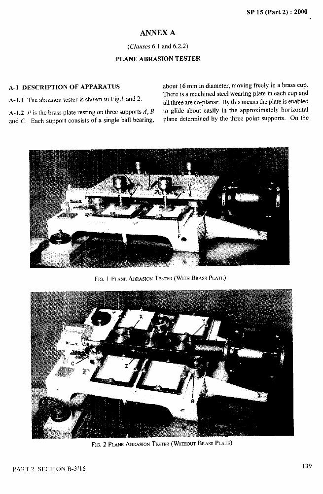
ANNEX A
(Clauses 6.1 and 6.2.2)
PLANE ABRASION TESTER
SP 15 (Part 2) :2000...-. .—
—...
A-1 DESCRIPTION OF APPARATUS about 16 mm in diameter, moving freely in a brass cup.
A-1.1 The abrasion tester is shown in Fig. 1 and 2.There is a machined steel wearing plate in each cup and
all three are co-planar. By this means the plate is enabled
A-1.2 P is the brass ~late resting on three supports A, B to glide about easily in the approximately horizontal.-. .
and C. Each support consists of a single ball bearing, plane determined by the three point supports. on me
FIG. 1 PLANEABRASIONTESTER(WITHBRASSPLATE)
)%..
PART 2, SECTION B-3/l 6139

SP 15 (Part 2) :2000
lower side of the plate are three steel plates machined
flat and co-planar which provide upper wearing surface
for the ball bearings. The plate is given the resultant
movement of two simple harmonic motions at right
angles in such a way that every point on it traces out a
path known as Lissajous figure (see Fig.3). This is the
result of the relative motion of two outer pegs (Xand Y)
which are synchronized and driven at the same speed of
47.5 +2 rev per min while the inner peg(s) rotate(s) at a
slightly lesser speed than the outer pegs with the speeds
in the ratio of 30:32. The total stroke of outer pegs as
well as inner pegs is 60.5 mm.
FIG. 3 LtSSAJOUSFIGURE,TRACEDBY PLATE(PLANEABRASIONTESTER)
A-1.3 There are recesses on two sides of the plate intowhich the four specimen holders (Hl, Hz, HJ and HJ canbe fitted. Each of the specimen holder rests upon one ofthe four small abrading tables whose surfaces are alsoflat and parallel to the plane in which the plate glides.These have the freedom of movement in vertical planebut must take part in the horizontal movement of theplate. The cloth specimens in the holders are rubbed onone of the surface of the abrading table, the path of eachbeing the Lissajous figure.
A-2 BACKING FOR SPECIMENS
A-2.1 Four circular pieces (38 mm diameter) ofpolyurethane foam approximately 3 mm thick and ofdensity approximately 0.04 g/cm3 are used for backingthe specimens. These are renewed when they becomeworn or soiled with use.
A-3 CLOTH SPECIMEN HOLDER
A-3.1 Each specimen holder consists of three parts, A,B and C (Fig. 4). A is a ring into which the cloth disc D,
38 mm in diameter, fits exactly. The working area ofspecimen holder is 6.45 cmz. B is a kind of circularplunger which is put in on top of the cloth and C isscrewed down over the outside of A. It then squeezesthe plunger against the rim of A, gripping the cloth andas the plunger B protrudes slightly through A, the clothis tensioned. In order to obtain a satisfactory tension thespecimens are mounted by pressing the holder downagainst the flat surface of the brass plate provided in the
base of the apparatus. A loaded specimen holder is shownin Fig. 5. With this device, the specimens may be
removed at any stage of abrasion testing and weighed.They can easily be put back into the holders for furtherrubbing exactly the same portion of the cloth beingexposed.
A-3.2 The machine makes about 3000 rubslh (one rubbeing a complete revolution of each cloth holder) and isfitted with a revolution counter and switch to stop themachine after a predetermined number of rubs.
EL
D A
FIG. 4 CLOTHSPECIMENHOLDER(PLANEABRASIONTESTER)
A-4 ABRADING TABLE
A-4.1 There are four square abrasion tables, one foreach specimen holder. They are made of cast iron andmachined flat. The surface against which the 38 mmdisc is to be rubbed shall be the abrasive fabric specimenor zero emery polishing paper as has been agreed tobetween the buyer and the seller.
\,4.!.
140 PART 2, SECTION B-3/16
/
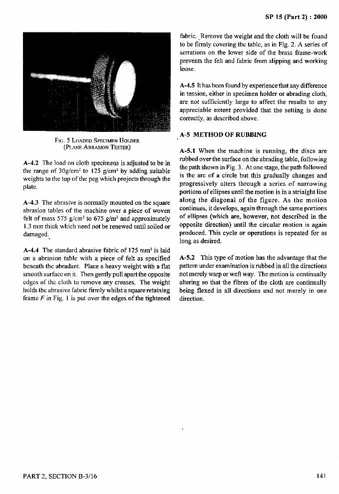
SP 15 (Part 2) :2000.. ___
FIG. 5 LOADEDSPECIMENHOLDER(PLANEABRASIONTESTER)
A-4.2 The load on cloth specimens is adjusted to be inthe range of 30g/cm2 to 125 g/cm2 by adding suitableweights to the top of the peg which projects through theplate.
A-4.3 The abrasive is normally mounted on the squareabrasion tables of the machine over a piece of wovenfelt of mass 575 g/cm2 to 675 g/m2 and approximately1.3 mm thick which need not be renewed until soiled ordamaged. .
A-4.4 The standard abrasive fabric of 125 mmz is laid
on a abrasion table with a piece of felt as specifiedbeneath the abradant. Place a heavy weight with a flatsmooth surface on it. Then gently pull apart the oppositeedges of the cloth to remove any creases. The weightholds the abrasive fabric firmly whilst a square retainingframe Fin Fig. 1 is put over the edges of the tightened
fabric. ,Remove the weight and the cloth will be found
to be firmly covering the table, as in Fig. 2. A series of
serrations on the lower side of the brass frame-work
prevents the felt and fabric from slipping and working
loose.
A-4.5 It has been found by experience that any difference
in tension, either in specimen holder or abrading cloth,
are not sufficiently large to affect the results to any
appreciable extent provided that the setting is done
correctly, as described above.
A-5 METHOD OF RUBBING
A-5. 1 When the machine is running, the discs are
rubbed over the surface on the abrading table, following
the path shown in Fig. 3. Atone stage, the path followed
is the arc of a circle but this gradually changes and
progressively alters through a series of narrowing
portions of ellipses until the motion is in a striaight line
along the diagonal of the figure. As the motion
continues, it develops, again through the same portions
of ellipses (which are, however, not described in the
opposite direction) until the circular motion is again
produced. This cycle or operations is repeated for as
long as desired.
A-5.2 This type of motion has the advantage that the
pattern under examination is rubbed in all the directions
not merely warp or wefl way. The motion is continually
altering so that the fibres of the cloth are continually
being flexed in all directions and not merely in one
direction.
.—. ii..1
‘
PART 2, SECTION B-3/16
/
141

—SP 15 (Part 2) :2000
ANNEX B
(Clauses 6.1 and 6.3.2)
PLANE ABRASION TESTER
—
B-1 DESCRIPTION OF APPARATUS
The plane abrasion tester shown in Fig. 6 consists of thefollowing parts.
B-1.l Surface Abrasion Head
The specimen is mounted in a circular clamp over a
rubber diaphragm by means of a clamping ring anda tightening collar. The circular opening of the
clamping ring is 94.0 mm + 1.3 mm in diameter and
that of the collar 95.3 mm or more. The height fromthe surface of the clamped in specimen to the upperedge of the tightening collar shall not exceed 9.5 mm.The clamping area of the body of the clamp and thering should have gripping surfaces to preventslipping of the specimen and leakage of air presureduring the test. Means should be provided for
applying air pressure to the body of the clamp sothat the pressure under the diaphragm can becontrolled between O and 0.4 kgf/cm2 with anaccuracy of+ 5 percent.
-.
142
FIG. 6 PLANEABRASIONTESTER
PART 2, SECTION B-3/l 6

SP 15 (Part 2) :2000
B-1.2 Diaphragm
The rubber diaphragm should be 1.40 mm + 0.25 mm inthickness. A metallic contact pin 3.2 mm in diameter issealed into the centre of the diaphragm flush with thediaphragm surface. Provision should be made for aflexible electrical connection from this contact pin tothe ground of the machine. The strain distribution onthe diaphragm must be uniform so that when inflatedwithout the specimen, it assumes the shape of a sphere.
B-1.3 Driving Mechanism
The design of the driving mechanism is such that thecircular clamp makes a reciprocal motion of 115+15double strokes per minute of 25 mm stroke length.Provision should be made for the rotation of the clampin addition to the reciprocating motion so that onerevolution can be completed in not less than 50 and notmore than 100 double strokes.
abradant plate assembly should be well balanced to e
maintain a vertical pressure equivalent to a mass of Oto i2270 g dead weights. Provision should be made to mount
different abradants, such as, abrasive paper, fabrics, etc,
‘y
,,;~:, ...
on this plate, and to stretch them into an even position.,+
An electrically insulated contact pin, adjustable to the
thickness of the abradant is mounted into this plate on
the length axis at one of the turning points of the centre
of the clamp.
B-1.4.2 The inflated diaphragm tester can also be
equipped with a continuous changing abradant head
which is available from the machine manufacturer.
B-1.5 Machine Stopping Mechanism
Contact between the adjustable pin on the lower side of
the abradant plate and the contact pin inserted into the
centre of the diaphragm closes a low voltage circuit and
stops the machine.
B-1.4 Balance Head and Abradant PlateB-1.6 Indicator
B-1 .4.1 The abradant is mounted upon a plate, which is
rigidly supported by double-lever parallelogram to
provide for free movement in a direction perpendicular
to the plane of the reciprocating specimen-clamp. The
Means should be provided for indicating the diaphragm
pressure and the number of abrasion cycles (1 cycle
= 1 double stroke).
PART 2, SECTION B-3/16
/
143
!

SP 15 (Part 2) :2000
‘r.. t+<
I%
ANNEX C
(Clause 7.2)
FLEX ABRASION TESTER
C-1 DESCRIPTION OF APPARATUS
The flex abrasion tester has following essential parts.
C-1.l Balance Head and Flex Block Assembly
The assembly should be of two parallel, smooth plates,one of which makes a reciprocating motionof115 + 15double strokes per minute, of 25 mm stroke-length. Theother plate is rigidly supported by a double leverassembly to provide free movement in a directionperpendicular to the plate of the reciprocating plate. Thisplate is stationary during the test and must be well
balanced so that a vertical load can be maintained bymeans of dead weights. The plates are equipped withclamps to permit the specimen, after it has been foldedaround the bar, to be aligned with its long dimensionparallel to the axis of the reciprocal motion and
equidistant from the edges of the plates. The clampshave gripping surfaces adequate to prevent slipping ofthe specimen during the test.
C-1.2 Flexing Bar Blade
C-1.2.1 A bar or blade is fixed depending on thespecification. Flex bars with the tester have beenstandardized.
C-1.2.2 The flex bars should be of 1.6 mm+ 0.4 mm by11.2 mm+ 1.6 mm cross section. It should be made oftool steel tipped with an edge of cemented carbide orother highly wear resistant material. The top, bottomand the edge of the bar which will be in contact with thespecimen, should be finally finished by grinding andpolishing, which levels off the microscopic projectionswithout breaking the edges of the bar.
C-1.2.3 The folding blade should be made of tool steel0.3 mm+ 0.13 mm by 25.4 mm+ 1.6mm in cross section,having radius of curvature of 0.13 mm* 0.02 mm andwell polished. The bar and blade should be of such lengthto properly fit the yoke (tension device) employed.
C-1.2.4 Before a new unstandardized bar or blade isused for testing, it should be placed in the tester andreceive to at least 20 000 cycles of abrasion using a64-mm fabric strip under a tensionof2270 g. A plied
144
yarn grey cotton duck, weighing from 400 g/m2 to
500 g/m2 is a suitable fabric strip for this purpose. The
bar or blade should then be standardized by comparing
its abrasion level to that of a master standard bar or blade
reserved for standardization purposes only. This
comparison should be carried out on a fabric with highly
unifo~ abrasion resistance, preferably a plain weave
fabric. Where the abrasion level of the bar or blade differs
by more than* 10 percent from the level of the master
standard bar or blade, the bar or blade should be reground
or otherwise reworked until its abrasion level is within +
10 percent of that of the master standard.
C-1.2.5 The testing bar should be restandardized on a
regular schedule either weekly or monthly depending
upon the amount of use of the given testing bar. Where
the abrasion level of the bar or blade differs by moreth~ + 10 percent flom the level of the master standard
bar or blade, the bar or blade should be reground or
otherwise reworked until the abrasion level is within+ 10
percent of that of the master standard bar or blade. The
same fabric should be used for restandardization as was
used for initial standardization. A standardized fabric is
available fi-om the equipment manufacturer.
C-1.3 Tension Device (Yoke)
A means for applying force to the folding bar or blade,
with the force acting parallel to the surface of the two
plates and perpendicular to the fold of the specimen to
produce a tension evenly distributed across the fold of
the specimen. The bar or blade should be prevented from
tilting or rotating around its principal axis by providing
means for rigidly clamping the bar to the yoke. The bar
yoke used for applying tension to the bar must be
sufficiently rigid to prevent its distortion, with consequent
impairment of bar position, during handling and
specimen loading.
C-1.4 Yoke-Positioning Device
Means should be provided to position the bar and yoke
properly while loading the specimen, in order to maintainthe proper bar alignment and to remove the positioning
PART 2 ;SECTION B-3/16
$r
/
-. ....SP 15 (Part 2) :2000
device from contact with the yoke atler the specimen
has been loaded and before the start of the test. Proper
bar alignment is a critical factor in this test and is
regulated by the length of the cables attaching the yoke
to the loading platform. The proper alignment shouldbe checked by abrading a strip of fabric and notingwhether the bar shifts laterally to either side of normalrest position during the course of abrasion. Such shiftingis indicative of improper bar alignment and should beadjusted by shortening or lengthening the proper cableuntil the shifting is no longer observed. After the propercable length has been achieved, the cables should be
PART 2, SECTION B-3/16
clamped securely by means of locknuts to preventsubsequent change in length.
C-1.5 Machine Stopping Mechanism
A microswitch actuated by the weight rack stops themachine when the test specimen ruptures:
C-1.6 Indicator
Means are provided for indicating the number of cycle(1 cycle= 1 double stroke).
ii,.,
145
/
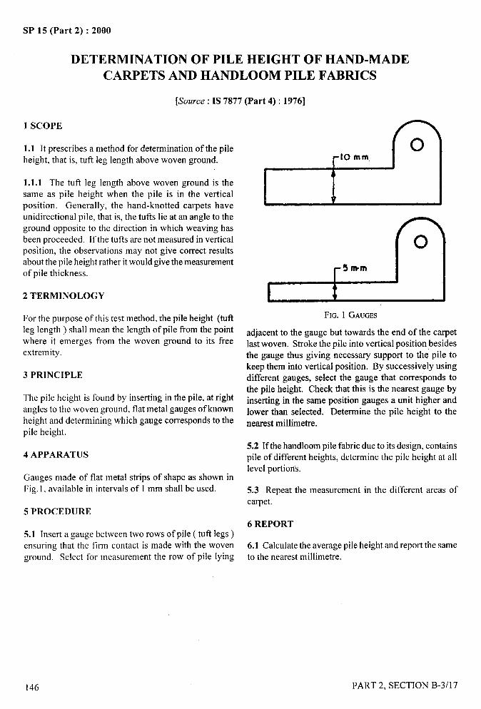
SP 15 (Part 2) :2000
DETERMINATION OF PILE HEIGHT OF HAND-MADE
CARPETS AND HANDLOOM PILE FABRICS
[Source : IS 7877 (Part 4) : 1976]
1 SCOPE
1.1 It prescribes a method for determination of the pileheight, that is, tuft leg length above woven ground.
1.1.1 The tufl leg length above woven ground is the
same as pile height when the pile is in the verticalposition. Generally, the hand-knotted carpets haveunidirectional pile, that is, the tufts lie at an angle to theground opposite to the direction in which weaving hasbeen proceeded. If the tufts are not measured in verticalposition, the observations may not give correct resultsabout the pile height rather it would give the measurementof pile thickness.
2 TERMINOLOGY
For the purpose of this test method, the pile height (tuftleg length ) shall mean the length of pile from the pointwhere it emerges from the woven ground to its freeextremity.
3 PRINCIPLE
The pile height is found by inserting in the pile, at rightangles to the woven ground, flat metal gauges of knownheight and determining which gauge corresponds to the
pile height.
4 APPARATUS
Gauges made of flat metal strips of shape as shown inFig. 1, available in intervals of 1 mm shall be used.
5 PROCEDURE
5.1 Insert a gauge between two rows of pile ( tuft legs)ensuring that the firm contact is made with the wovenground. Select for measurement the row of pile lying
FIG. 1 GAUGES
adjacent to the gauge but towards the end of the carpetlast woven. Stroke the pile into vertical position besidesthe gauge thus giving necessary support to the pile tokeep them into vertical position. By successively usingdifferent gauges, select the gauge that corresponds tothe pile height. Check that this is the nearest gauge byinserting in the same position gauges a unit higher andlower than selected. Determine the pile height to thenearest millimetre.
5.2 If the handloom pile fabric due to its design, containspile of different heights, determine the pile height at alllevel portions.
5.3 Repeat the measurement in the different areas ofcarpet.
6 REPORT
6.1 Calculate the average pile height and report the sameto the nearest millimetre.
j---
!
,
J!!,,...
146
/
PART 2, SECTION B-3/17
I I!!!I
SP 15 (Part 2) :2000
DETERMINATION OF TERRY RATIO
OF TOWELLING FABRICS
-- -.-j(Source : IS 7056:1989)
1 SCOPE
It provides a method for determination of terry ratio of
towelling fabrics.
2 TERMINOLOGY
For the purpose of this test method following definition
shall apply.
2.1 Terry Ratio
Ratio of straightened length of terry warp threads to the
mean straightened length of the ground warp threads.
3 SAMPLING
Sample taken from the lot shall be drawn so as to be
representative of the lot. Sample drawn in accordance
with the relevant material specification or as agreed to
between the buyer and the seller shall be representative
of the lot.
4 ATMOSPHERIC CONDITIONS FORCONDITIONING AND TESTING
4.1 Prior to evaluation, the fabric pieces shall beconditioned to moisture equilibrium in the standardatmosphere of 65 + 2 percent relative humidity and27+ 2°C temperature from dry side (see section B- 1/1).
4.2 Testing shall be caried out in standard atmsophere(see 4.1).
5 PROCEDURE
Cut out a 10 cm x 10 cm specimen fi-om the fabric andcondition the specimen in the standard atmosphere fortesting. Remove warp threads each from the specimenof ground warp and of terry warp, Determine the meanstraightened length of each group of 10 threads.
6 CALCULATION
Express the terry ratio as the ratio of the mean
straightened length of the terry warp threads to the meanstraightened length of the ground warp threads.
/
PART 2, SECTION B-3/l 8 147
1I
I I
I I
SP 15 (Part 2) :2000
DETERMINATION OF WEFT DISTORTION OF
JUTE CARPET BACKING FABRIC
[Source : IS 4900 (Part 1):1984]
Weft distortion in jute carpet backing may result in distortion of the pattern of the pile surface tufted into it.
I SCOPE
It prescribes measurement ofwetl distortion (bow, bias,combined bow and bias and weft fall-off ) in jute carpetbacking fabric. It is applicable to all woven jute backingfabrics.
2 SUMMARY OF METHOD
Weft distortion is classified into four types: bows, bias,combined bow and skewness, and weft fall-off. Thereare two conditions of measurement(a) unrolling a portionof the roll, laying it flat without tension on a horizontalsurface and making measurements, or (b) bymeasurement on the roll at the back of the rollingmachine. This method is most suitable for the backingmanufacturer.
A reference line perpendicular to the selvedges is drawnon the fabric. The distortion of a wefi yam is measuredin relation to the reference line.
3 COND1TION1NG
The fabric need not be conditioned or pre-conditionedfor measurement of filling distortion.
4 APPARATUS
4.1 Racks and mandrels for unwinding the roll of fabric.
4.2 Flat surface at least 3 m (3 yd) long, and at least150 mm (6 in) wider than the fabric to be measured.
4.3 Measuring Tape or Line
Long enough so that a perpendicular can be droped from
a point on one selvedge to the opposite point (plumplines).
5 PROCEDURE
5.1 Measurement on a Flat Surface
5.1.1 Mount the roll to be measured on a mandrel andracks. Rotate the roll without pulling on the fabric.
148
Gently lay out 3 m ( 3 yd) ofcioth rm a smooth horizontalsurface without tension in any direction.
5.1.2 Trace one weft thread across the full width usinga sotl pencil or other suitable marker.
5.1.3 Measure bow by drawing a line AC (See Fig. 1A)between the points of intersection of the marked fillingthread and the selvedges. This line must be perpendicularto each selvedge. Assume bow of a pick corresponds tothe curved line ABC of Fig. 1 A. Point B is the greatestdistance of filling pick ABC from the line AC. Draw aperpendicular from point B to the line AC interesting it
at D. Measure the distance BD to the nearest 2.5 mm(O.1 in).
5.1.4 Measure bias by tracing the position of one pickas directed in 5.1.2. Assume that this positioncorresponds to the line AC in Fig. I B. Draw a lineperpendicular to the selvedge across the fabric from thepoint C, where the marked pick meets one selvedge,meeting the other shown in Fig. 1B, to the nearest2.5 mm (0.1 in).
5.1.5 Measure combined bow and bias by tracing theposition of one pick as directed in 5.1.2. Assume thatthis position corresponds to the line ABC in Fig. 1C. AtC, where the pick meets the selvedge, draw aperpendicular across the fabric meeting the oppositeselvedge at point D. Point B is the greatest distance ofthe pick ABC from the line DC. Draw a perpendicularfrom point B to the line DC. Measure the distanceBE between point B and the intersection E, ofthe perpendicular and line DC to the nearest 2.5 mm(0.1 in).
5.1.6 Measure weft fall-off on a selected filling yarnAC (see Fig. 1D). Draw a reference line (the referenceline may be drawn using a chalked string) perpendicularto the selvedges. At a point Bon the selected weft yarn,draw a perpendicular to the reference line. Measure thedistance along the perpendicular from the point to thereference line to the nearest 2.5 mm (O.1in). From thepoint of intersection E measure 300 mm (12 in) alongthe reference line. At the point E erect a perpendicular
PART 2, SECTION B-3/l 9
—.:
II1,
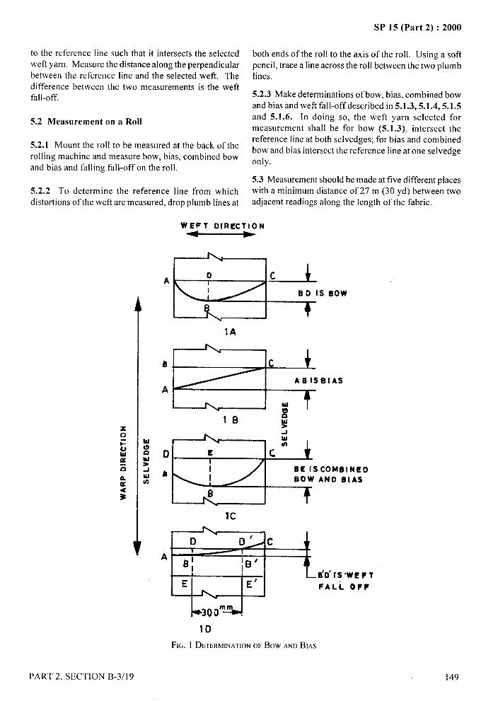
_
---
SP 15 (Part 2) :2000
to the reference line such that it intersects the selectedweft yarn. Measure the distance along the perpendicularbetween the reference line and the selected weft. The
difference between the two measurements is the weftfall-off.
5.2 Measurement on a Roll
5.2.1 Mount the roll to be measured at the back of therolling machine and measure bow, bias, combined bowand bias and falling fall-off on the roll.
5.2.2 To determine the reference line from whichdistortions of the weft are measured, drop plumb lines at
A
8.
both ends of the roll to the axis of the roll. Using a soft -- -Y
pencil, trace a line across the roll between the two plumblines.
!
5.2.3 Make determinations of bow, bias, combined bow1
.. --,
and bias and weft fall-off described in 5.1.3,5 .1.4,5.1.5 ‘<and 5.1.6. In doing so, the weft yarn selected formeasurement shall be for bow (5.1 .3), intersect thereference line at both selvedges; for bias and combinedbow and bias intersect the reference line atone selvedgeonly.
5.3 Measurement should be made at five different placeswith a minimum distance of27 m (30 yd) between twoadjacent readings along the length of the fabric.
WEFT DIRECTION
I
o L-LBo is eow
+
‘M’”slB
-1wUI
D E cI
hI BE lSCOMOINEDI SOW AND 61’S
Ic
D D> c
A ~ ~0; lBO
I
EB’D’r S”WEFT
E’ FALi. OFF
~,,,”dID
FIG. 1 DETERMINATIONOFBow ANDBIAS
PART 2, SECTION B-3/19
/
149
I{
!1I \I
4-
. ....—SP 15 (Part 2) :2000
6 CALCULATION OF RESULTS
6.1 If the weft distortion at any point of measurement isnot on the same side of reference line, measure weftdistortion at both the sides of reference line separatelyand add them to have the average value.
6.2 Compute the average of the five measurements ofweft distortion to the nearest 2.5 mm (0.1 in).
150
7 REPORT
Report the fol!owing information:
a)
b)
c)
The method of measurement, that is, on a flatsurface or on a roll;
The pattern of weft distortion observed at eachmeasurement; and
The average value as obtained in 6.2.
PART 2, SECTION B-3/19
\\!,.,
SP 15 (Part 2) :2000
DETERMINATION OF CORRECT INVOICE .-
WEIGHT OF WOOLLEN FABRICS
(Source: IS 4902:1981) ‘~,; ,-.q
It prescribes a method for determination of correct invoice weight of woolen fabrics. For details of the method referto Section B-2/l 2.
PART 2, SECTION B-3/20 151
I

As in the Original Standard, this Page is Intentionally Left Blank
.-
SP 15 (Part 2) :2000
.i
SECTION C
PHYSICO-CHEMICAL TESTS
II II

As in the Original Standard, this Page is Intentionally Left Blank
,4-
SP 15 (Part 2) :2000
PREPARATION, MARKING AND MEASURING OF FABRIC
SPECIMENS AND GARMENTS IN TESTS FOR DETERMINATION OF
DIMENSIONAL CHANGE
(Source : IS 10099:1982)
Dimensional stability of fabrics and garments is an important characteristic. Therefore, the measurement ofdimensional change due to various treatments like washing, dry cleaning, soaking in water, steaming, etc, is verynecessary. Preparation, marking and measuring of fabric specimens and garments before and atler treatment is asimportant as the testing procedures for accurate and reliable results; this test method has been doveloped to avoid
discrepancies in this area.
1 SCOPE
This standard prescribes methods for the preparation,marking and measuring of fabric specimens (except textile
floor coverings) and garments for use in tests for
determining dimensional change (for example,
dimensional change on washing, dry cleaning, soaking
in water, or steaming).
2 PRINCIPLE
Specimens are selected so as to be as representative as
possible of the sample. Pairs of reference marks are placedon the fabric specimen or garment and the distance
between the two marks of each pair of reference marks is
measured before and atler specified treatment.
3 APPARATUS
3.1 Rule
Not less than 750 mm length, preferably with an engraved,
bevelled edge, marked in millimeters, for measuringfabric specimens.
3.2 Flexible Steel Rule or Fibre-G1ass Tape
Marked in millimetres, for measuring garments.
3.3 Suitable Means of Marking Reference Points
Such as:
a) Indelible ink;
b) Fine threads, of colour contrasting with the
fabric;
c) Heated wire, with which small holes may be
made (for thermoplastic fabrics only); and
d) Staples, with the measurements made from thepoint of entry of the staple into the cloth.
PART 2, SECTION C/l
Indicate on the cloth which end of the staple isused for measurement.
3.4 Flat Table of dimensions such that the completearticle being tested can be laid flat for measurement.
4 ATMOSPHERIC CONDITIONS FOR
CONDITIONING AND TESTING
4.1 The test specimens shall be conditioned (after pre-
conditioning) to moisture equilibrium in standardatmosphere at 65 + 2 percent RH and 27+ 2°Ctemperature as given in 1S 6359:1971 ‘Method forconditioning of textiles’ reproduced in Section B-1/1before making measurements.
5 FABRIC SPECIMENS
5.1 Selection and Number
5.1.1 Selected specimens should be as representative aspossible of the sample. Take sufficient specimens to coverthe width of the fabric, but do not cut specimens fromwithin 1 m (preferably not within 3 m) of either end of apiece or where possible, within 75 mm of either selvedge.
5.2 Dimensions
5.2.1 Cut increased specimens, each measuring not lessthan 500 mm x 500 mm with edges parallel to the lengthand width of the fabric. In the case of fabrics less than650 mm in width, full-width specimens may be usedand measurements made by agreement between theinterested parties.
NOTE— Iftbereisapossibilityofthefabricunravelingduringthetestprocedure,overlocktheedgesof thespecimenwithdimensionallystablethread.Specimenstreatedintbk wayshallbe cutslightlylargerthanthe specifieddimensions.Specimensofwetl knittedfabricsshallbe ofdouble-thickness and the edges shall be overstiched looselyusingdimensionallystablethread.
155
—.;
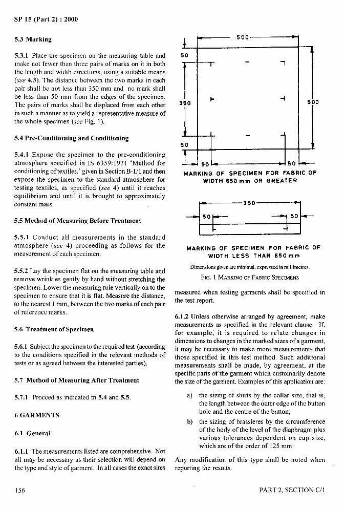
4-
SP 15 (Part 2) :2000
5.3 Marking
5.3.1 Place the specimen on the measuring table andmake not fewer than three pairs of marks on it in boththe length and width directions, using a suitable means(see 4.3). The distance between the two marks in each
pair shall be not less than 350 mm and no mark shallbe less than 50 mm from the edges of the specimen.
The pairs of marks shall be displaced from each otherin such a manner as to yield a representative measure of
the whole specimen (see Fig. 1).
5.4 Pre-Conditioning and Conditioning
5.4.1 Expose the specimen to the pre-conditioning
atmosphere specified in IS 6359:1971 ‘Method forconditioning of textiles.’ given in Section B-1/1 and then
expose the specimen to the standard atmosphere for
testing textiles, as specified (see 4) until it reachesequilibrium and until it is brought to approximately
constant mass.
5.5 Method of Measuring Before Treatment
5.5.1 Conduct all measurements in the standard
atmosphere (see 4) proceeding as follows for themeasurement of each specimen.
5.5.2 Lay the specimen flat on the measuring table andremove wrinkles gently by hand without stretching the
specimen. Lower the measuring rule vertically onto the
specimen to ensure that it is flat. Measure the distance,to the nearest 1 mm, between the two marks of each pair
of reference marks.
5.6 Treatment of Specimen
5.6.1 Subject the specimen to the required test (accordingto the conditions specified in the relevant methods of
tests or as agreed between the interested parties).
5.7 Method of Measuring After Treatment
5.7.1 Proceed as indicated in 5.4 and 5.5.
6 GARMENTS
6.1 General
6.1.1 The measurements listed are comprehensive. Not
all may be necessary as their selection will depend onthe type and style of garment. In all cases the exact sites
156
L50
r350
1
50
~
1
1- +
--l .
50 450
MARKING OF SPECIMEN FOR FABRIC OF
WIDTH 650 mm OR GREATER
*
MARKING OF SPECIMEN FOR FABRIC OF
WIDTH LESS THAN 650 mm
Dimensionsgiven are minimal, expressedin millimetres.
FIG. 1 MARRINGOFFABRICSPECIMENS
measured when testi~g garments shall be specified inthe test report.
6.1.2 Unless otherwise arranged by agreement, makemeasurements as specified in the relevant clause. If,for example; it is required to relate changes indimensions to changes in the marked sizes of a garment,it may be necessary to make more measurements thatthose specified in this test method. Such additionalmeasurements shall be made, by agreement, at thespecific parts of the garment which customarily denotethe size of the garment. Examples of this application are:
a) the sizing of shirts by the collar size, that is,the length between the outer edge of the buttonhole and the centre of the button;
b) the sizing of brassieres by the circumferenceof the body of the level of the diaphragm plusvarious tolerances dependent on cup size,which are of the order of 125 mm.
Any modification of this type shall be noted whenreporting the results.
PART 2, SECTION C/l
.—
\?”(.
/
I
!
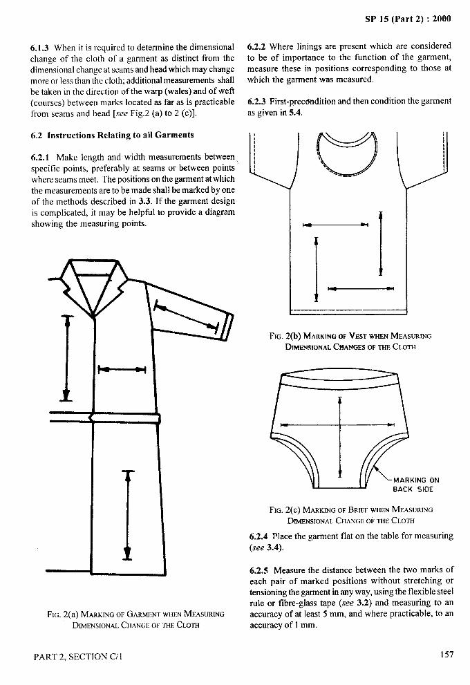
6.1.3 When it is required to determine the dimensionalchange of the cloth of a garment as distinct from thedimensional change at seams and head which may changemore or less than the cloth; additional measurements shallbe taken in the direction of the warp (wales) and of weft(courses) between marks located as far as is practicablefrom seams and head [see Fig.2 (a) to 2 (c)].
6.2 Instructions Relating tq all Garments
6.2.1 Make length and width measurements betweenspecific points, preferably at seams or between pointswhere seams meet. The positions on the garment at whichthe measurements are to be made shall be marked by oneof the methods described in 3.3. If the garment designis complicated, it may be helpful to provide a diagramshowing the measuring points.
IFIG. 2(a) MARKINGOFGARMENTWHENMEASURING
DIMENSIONALCHANGEOFm CLOTH
PART 2, SECTION C/l
SP 15 (Part 2) :2000
6.2.2 Where linings are present which are consideredto be of importance to the function of the garment,measure these in positions corresponding to those atwhich the garment was measured.
6.2.3 First-precondition and then condition the garmentas given in 5.4.
-ImIm
.--. -—-. ——— —.. ——-----
FIG. 2(b) MARKHWOFVESTWHENMEASURINGDIMENSIONALCFfANGESOFTHECLOTH
MARKING ONBACK SIOE
FIG. 2(c) MARKINGOFBRIEFWHENMEASURINGDIMENSIONALCHANGEOFTHECLOTH
6.2.4 Place the garment flat on the table for measuring
(see 3.4).
6.2.5 Measure the distance between the two marks ofeach pair of marked positions without stretching ortensioning the garment in anyway, using the flexible steelrule or fibre-glass tape (see 3.2) and measuring to anaccuracy of at least 5 mm, and where practicable, to anaccuracy of 1 mm.
157
/
I
I

SP 15 (Part 2) :2000
6.2.6 Measure the width or circumference with the along the fold. Measure the fold between side seams, or
garment closed and ensure that the buttons of buttoned between sleeve seams, or between panels, depending on
garments are fully home in the buttonholes. the construction of the garment.
6.2.7 Measure elasticated garments or portions of 6.3.1.8 Width across back between sleeve seamsgarments in the relaxed state. measured at a distance halfivay between centre-back neck
and lowest point of armhole, or width or yoke from sleeve6.3 Specific Positions for Measurements seam to sleeve seam.
The following measuring positions are recommendedbut not all positions are necessarily relevant to allgarments of a particular type. Correspondingmeasurements shall be made on both halves of thegarment under examination, for example, both sleeves.
6.3.1 Jacket-Like Garments (jor Example, Dresses,
Coats, PulIovers, Pyjamas, Shirts, Vests)
The measuring positions are the following.
6.3.1.1 Length ofneck-band
6.3.1.2 Vertical length from lowest point of armhole tobottom of garment.
6.3.1.3 Vertical length of fkont fi-omjunction of shoulderseam and neck seam to bottom of garment.
6.3.1.9 Width or circumference of garment at not morethan three places at stated distances ti-om the centre-backneck.
6.3.1,10 Width or circumference of sleeve from junctionof side and sleeve seams at right angles to sleeve length.
6.3.1.11 Width from front sleeve seam junction with thebody to the back sleeve seam junction with the body, asshown in Fig. 4.
6.3.1.12 Width or circumference or sleeve halfwaybetween lowest point of armhole and bottom of sleeve.
6,3.1.13 Width or circumference at cuff or bottom ofsleeve.
6.3.1.4 Vertical length of centre back from neck to bottomof garment.
6.3.1.5 Length of underarm seam(s) from armhole tobottom of sleeve.
There may be two such seams if the sleeve is made fromupper and lower sleeve sections: both shall be measured.
6.3.1.6 Length of shoulder seam from sleeve seam toneck.
6.3.1.7 Where applicable, the garment shall be foldedas shown in Fig. 3 with the widest part of the bust section,
FIG. 4 MEASUREMENTDESCRIBED
6.3.2 Trousers ~or example, Briefs, Pants, Swim,
Trunks)
The measuring positions are the following:
6.3.2.1 Length Ilom top to junction of leg seams atfront.
FIG. 3 METHODOFFOLDINGGARMENT
6.3.2.2 Length from top to junction of leg seams atback. If seams are curved, measure round the curves. Ifthere is more than one seam measure all seams.
—..
),
158 PART 2, SECTION C/l
( Ii’;I
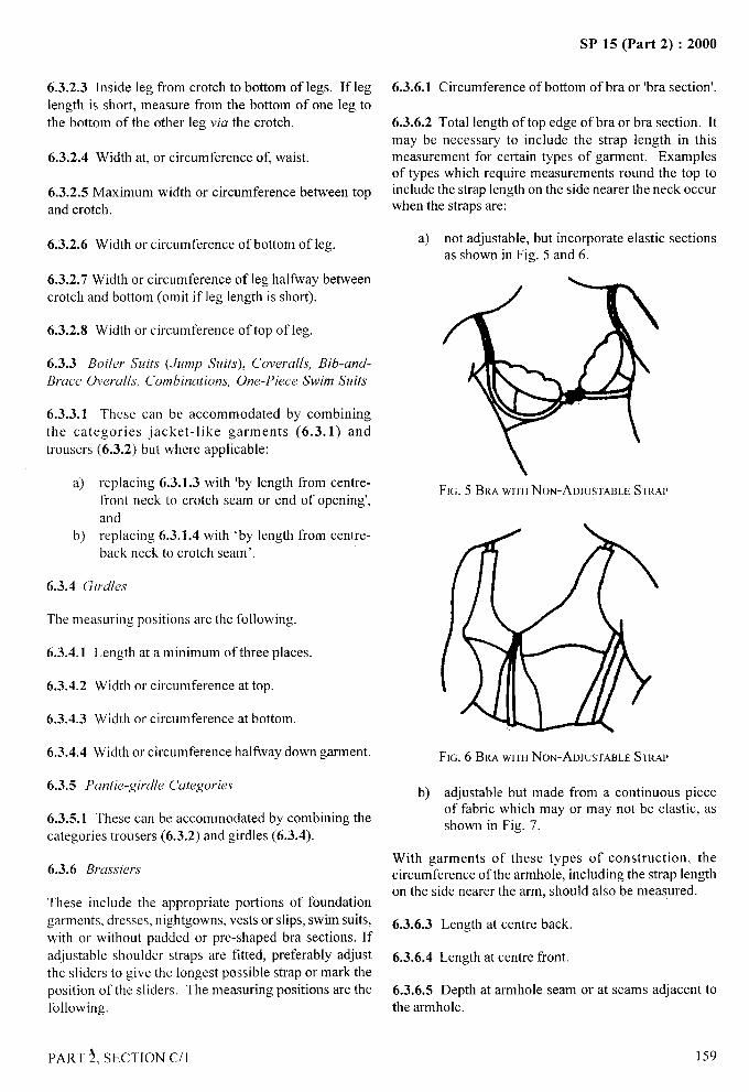
SP 15 (Part 2) :2000
6.3.2.3 Inside leg from crotch to bottom of legs. If leglength is short, measure from the bottom of one leg tothe bottom of the other leg via the crotch.
6.3.2.4 Width at, or circumference of, waist.
6.3.2.5 Maximum width or circumference between topand crotch.
6.3.2.6 Width or circumference of bottom of leg.
6.3.2.7 Width or circumference of leg halfway betweencrotch and bottom (omit if leg length is short).
6.3.2.8 Width or circumference of top of leg.
6.3.3 Boiler Suits (Jump Suits), Coveralls, Bib-and-
Brace (herall.s, Combinations, One-Piece Swim Suits
6.3.3.1 These can be accommodated by combiningthe categories jacket-like garments (6.3.1) andtrousers (6.3.2) but where applicable:
a) replacing 6.3.1.3 with ‘by length from centre-fi-ont neck to crotch seam or end of opening’,
andb) replacing 6.3.1.4 with ‘by length from centre-
back neck to crotch seam’.
6.3.4 (lirdles
The measuring positions are the following.
6.3.4.1
6.3.4.2
6.3.4.3
6.3.4.4
Length at a minimum of three places.
Width or circumference at top.
Width or circumference at bottom.
Width or circumference halfway down garment.
6.3.5 Pantie-girdle Categories
6.3.5.1 These can be accommodated by combining thecategories trousers (6.3.2) and girdles (6.3.4).
6.3.6 Brassiers
These include the appropriate portions of foundation
garments, dresses, nightgowns, vests or slips, swim suits,with or without padded or pre-shaped bra sections. Ifadjustable shoulder straps are fitted, preferably adjustthe sliders to give the longest possible strap or mark theposition of the sliders. The measuring positions are thefollowing.
PART ~, SECTION C/l
6.3.6.1 Circumference of bottom of bra or ‘bra section’.
6.3.6.2 Total length of top edge of bra or bra section. Itmay be necessary to include the strap length in thismeasurement for certain types of garment. Examplesof types which require measurements round the top toinchrde the strap length on the side nearer the neck occurwhen the straps are:
a) not adjustable, but incorporate elastic sectionsas shown in Fig. 5 and 6.
-- -J
FIG. 5 BRAwm NON-AEIJUSTABLESTRAP
},
FIG. 6 BRAWJTEINON-ADJUSTABLESTRAP
b) adjustable but made from a continuous pieceof fabric which may or may not be elastic, asshown in Fig. 7.
With garments of these types of construction, thecircumference of the armhole, including the strap lengthon the side nearer the arm, should also be measured.
6.3.6.3 Length at centre back.
6.3.6.4 Length at centre front
6.3.6.5 Depth at armhole seam or at seams adjacent tothe armhole.
159
I
,t’
II
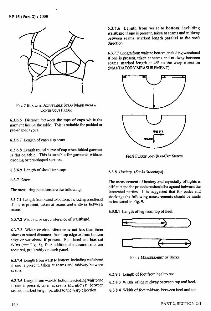
SP 15 (Part 2) :2000
‘1
6.3.7.6 Length from waist to bottom, includingwaistband if one is present, taken at seams and midwaybetween seams, marked length parallel to the weftdirection.
6.3.7.7 Length from waist to bottom, including waistbandif one is present, taken at seams and midway beweenseams, marked length at 45° to the warp direction(MANDATORY MEASUREMENT).
/
FIG. 7 BRA WITHADJUSTABLESTRAPMAOEFROMACONTINUOUSFABRIC
6.3.6.6 Distance between the tops of cups while thegarment lies on the table. This is suitable for padded orpre-shaped types.
6.3.6,7 Length of each cup seam.
6.3.6.8 Length round curve of cup when folded garmentis flat on table. This is suitable for garments without FIG.8 FLAREDANDBIAS-CUTSKIRTSpadding or pre-shaped sections.
6.3.6.9 Length of shoulder straps.
6.3.7 Skirts
The measuring positions are the following.
6.3.7.1 Length ffom waist to bottom, including waistbandif one is present, taken at seams and midway betweenseams.
6.3.7.2 Width at or circumference of waistband.
6.3.7.3 Width or circumference at not less than threeplaces at stated distances from top edge or from bottomedge or waistband if present. For flared and bias-cut
skirts (see Fig. 8), four additional measurements arerequired, preferably on each panel.
6.3.7.4 Length from waist to bottom, including waistbandif one is present, taken at seams and midway betweenseams.
6.3.7.5 Length from waist to bottom, including waistbandif one is present, taken at seams and midway betweenseams, marked length parallel to the warp direction.
6.3.8 Hosiev (Soc~ Stockings)
The measurement of hosiery and especially of tights isdifficult and the procedure should be agreed between theinterested parties. It is suggested that for socks and
stockings the following measurements should be madeas indicated in Fig. 9.
6.3.8.1 Length of leg from top of heel.
FIG. 9 MEASUREMENTOFSOCKS
6.3.8.2 Length of foot from heel to toe.
6.3.8.3 Width of leg midway between top and heel.
6.3.8.4 Width of foot midway between heel and toe
I
‘[
160 PART 2, SECTION C/l
/
.—-
SP 15 (Part 2) :2000
6.3.9 Hats and Caps
The measuring positions are the following.
6.3.9.1 Length of band.
6.3.9.2 Length of seams.
6.3.9.3 Width of band.
6.3.9.4 Overall diameter (inside dimension).
6.3.10 Gloves
6.3.10.1 Overall length.
6.3.10.2 Length of thumb seam(s).
6.3.10.3 Length along centre line of middle finger.
6.3.10.4 Width of pahn, above the thumb joint.
PART 2, SECTION C/l
6.3.10.5 Width across wrist at hem.
It maybe found helptid to use a template.
6.4 Treatment of Garment
Subject the garment to the required test method, repeatthe procedure described in 6.2.3 to 6.2.8 making
the same series of measurement as conducted
under 6.3.
7 EXPRESSION OF RESULTS
The changes in dimensions shall be recorded separately
as percentages of the original value. The changes in therecorded measurements may be reported as well as, or
instead of, the changes in dimensions. A plus sign(+)
shall be used to indicate elongation and a minus (–) to
indicate shrinkage.
161
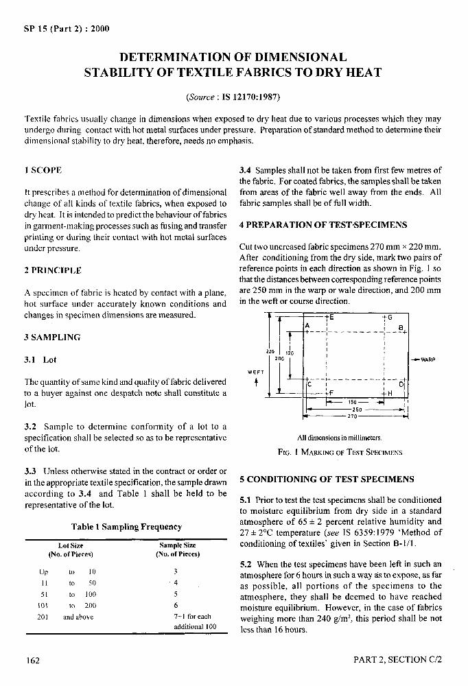
SP 15 (Part 2) :2000
DETERMI~ATION OF DIMENSIONAL
STABILITY OF TEXTILE FABRICS TO DRY HEAT
(Source : IS 12170:1987)
Textile fabrics usually change in dimensions when exposed to dry heat due to various processes which they may
undergo during contact with hot metal surfaces under pressure. Preparation of standard method to determine theirdimensional stability to dry heat, therefore, needs no emphasis.
1 SCOPE
[tprescribes a method for determination of dimensional
change of all kinds of textile fabrics, when exposed to
dry heat. It is intended to predict the behaviour of fabrics
in garment-making processes such as fhsing and transferprinting or during their contact with hot metal surfaces
under pressure.
2 PRINCIPLE
A specimen of fabric is heated by contact with a plane,hot surface under accurately known conditions and
changes in specimen dimensions are measured.
3 SAMPLING
3.1 Lot
The quantity of same kind and quality of fabric delivered
to a buyer against one despatch note shall constitute a
lot.
3.2 Sample to determine conformity of a lot to a
specification shall be selected so as to be representativeof the lot.
3.3 Unless otherwise stated in the contractor order or
in the appropriate textile specification, the sample drawn
according to 3.4 and Table 1 shall be held to be
representative of the lot.
Table 1 Sampling Frequency
Lot Size Sample Size(No. of Pieces) (No. of pieces)
(JP to 10 3
11 to 50 4
51 to 100 5
101 to 200 6
201 and above 7+1 for each
additional 100
3.4 Samples shall not be taken from first few metres ofthe fabric. For coated fabrics, the samples shall be takenfrom areas of the fabric well away from the ends. Allfabric samples shall be of fill width.
4 PREPARATION OF TEST’SPECIMENS
Cut two uncreased fabric specimens 270 mm x 220 mm.After conditioning from the dry side, mark two pairs ofreference points in each direction as shown in Fig. 1 sothat the distances between corresponding reference pointsare 250 mm in the warp or wale direction, and 200 mmin the weft or course direction.
.—
2’—.
WEF
t
rT ~~E -fG
Al 1
+–––;––-–----–:–-@+
I
2201
120
lL ~~
200 I -9 WARPI
T
+c___}. ___––_– &D+
1
L::’a
Alldimensionsin millimeters.
FIG. 1 MARKINGOFTESTSPECIMENS
5 CONDITIONING OF TEST SPECIMENS
5.1 Prior to test the test specimens shall be conditionedto moisture equilibrium from dry side in a standardatmosphere of 65 + 2 percent relative humidity and27+ 2°C temperature (see IS 6359:1979 ‘Method of iconditioning of textiles’ given in Section B-1/1. I
5.2 When the test specimens have been left in such an1,
atmosphere for 6 hours in such away as to expose, as faras possible, all portions of the specimens to the “~
atmosphere, they shall be deemed to have reachedmoisture equilibrium. However, in the case of fabrics Iweighing more than 240 g/m2, this period shall be not ~less than 16 hours.
162 PART 2, SECTION C/2
6APPARATUS
6.1 A Press
Consisting of a plane heated metal plate whose
temperature can be adjusted within the range 100 to
2 10°C with an accuracy of + 2°C, and a horizontal bed.
When closed, the press exerts a uniform pressure of
4 + 1 k Pa between the plate and bed. The bed is covered
by flexible and compressible cladding of low thermal
conductivity and heat capacity, which is capable of
conforming to slight variations in the thickness of
specimens or of the gap between plate and bed. The
cladding shall be unaffected by the highest temperature
used and shall not absorb moisture.
NOTE — A silicone foam rubber layer, supported on a lowdensity textile wadding has proved suitable for the claddingspecified in 6.1.
6.2 Specimen Holder
Consisting of a thin flexible sheet of material with low
friction and low heat capacity, larger than the heated plate,
and supported at its edges by a light frame which does
not impede contact between the plate and bed.
NOTE — A sheet of O.15mm thickness, polytetrafluoroethylenewith glass tibre reinforcement and a total mass per unit area of250ghn’, has been found suitable.
6.3 Steel Measuring Scale or Other Means of
Measuring Length
Accurate to 0.5 mm.
6.4 Means of Cutting Out and Marking Fabric
Specimens
Marking may be by notches, sewing thread, or other
means of equal precision that do not significantly increase
the thickness of the specimens.
7 PROCEDURE
7.1 Determine the dimensions All, CD: EF and GH of
the conditioned specimen to the nearest 0.5 mm.
7.2 Set the press at one or more of the following
temperatures, unless otherwise specified in the
appropriate textile specification, and leave the press
SP 15 (Part 2) :2000
closed until it reaches a steady state of temperature:
7.3
Test Temperature
Mild 150 + 2°c
Intermediate 180 + 2°C
Severe 210+2°c
Place the conditioned fabric specimen on the
specimen holder. Open the press, place the holder andspecimen in position on the bed and close the press sothat a pressure of 4 * 1 kPa is applied on the specimen.Leave the specimen in this condition for 30 seconds. Thenimmediately open the press and remove the specimenand holder.
NOTE — It is essential that the working area of the test press shallbe larger than the specimen size.
7.4 Condition the specimen in its flat state in the standardatmosphere, until the equilibrium is reached.
7.5 Measure the dimensions AB, CD, EF, GH of thespecimen to the nearest 0.5 mm.
7.6 Repeat the procedure with the second specimen.
8 CALCULATION AND EXPRESSION OFRESULTS
8.1 Calculate, for each specimen, the changes indimensions for each test length as follows:
Change in dimension (percent)=).
New Dimension ~ Original Dimension
Original Dimensionx 100
8.2 For each specimen, calculate the mean dimensionalchange in each direction.
9 REPORT
The report shall include the following:
a)
b)
c)
d)
Details of the samples tested;
The mean dimensional change in both directionsfor each specimen expressed as in 8;
The temperature used for testing; and
Any deviation from the test conditionsdescribed in 7.2 and 7.3.
PART 2, SECTION C/2
/
163
. —-.SP 15 (Part 2) :2000
DETERMINATION OF DIMENSIONAL CHANGES OF WOVEN
FABRICS ON WASHING NEAR THE BOILING POINT
(Source : IS 9:1982)
1 SCOPE
1.1 It prescribes a method for determining the
dimensional changes of woven fabrics on washing nearthe boiling point.
1.2 The method is mainly applicable to woven cottonand linen fabrics and their blends which are wasbed athig,h temperatures. The method is intended only for the
assessment of dimensional changes undergone by a
woven fabric subjected to single mechanical washing.
When it is desired to determine the amount of
progressive dimensional change, the test specimenshould be Jvashed repeatedly and the results reported so
as to clearly indicate the amount of dimensional changein the washed specimen as compared with original
dimensions of the unwashed specimen and the numberof testing cycles to which the specimen has been
subjected.
2 SAMPLING
2.1 Sample to determine conformity of a lot to a
specification shall be selected so as to be representativeof the lot.
2.2 Sample drawn in compliance with an agreement
between the buyer and the seller to evaluate the
dimensional changes on washing of cloth in the lot shallbe held to be representative of the lot.
3 TEST SPECIMENS
From the sample under analysis, draw three test
specimens, each being of a size such that its length is650 mm and of full width, taking care that (a) the
specimens are not drawn from within one metre of either
end of the piccc, (b) no two specimens are drawn from
the same piece, and (c) the specimens are cut and not
torn from the piece.
4 CONDITION1NG OF TEST SPECIMENS
4.1 Prior to test, the test specimens shall be conditioned
to moisture equilibrium in a standard atmosphere
at 65 +=2 percent relative humidity and 27+ 2°Ctemperature (.sce IS 6359:1971 ‘Method for
conditioning of textiles’ given in Section B-1/1), thevariation in temperature during any one series of testsshall not be more than 1°C.
4.2 When the test specimens have been left in such anatmosphere for 24 hours in such a way as to expose, asfar as possible, all portions of the specimens to theatmosphere, they shall be deemed to have reachedmoisture equilibrium. However, in the case of fabricswhich weigh more than 270 g/m2, this period shall be48 hours.
5 APPARATUS
5.1 Wash Wheel
5.1.1 A horizontal cylindrical machine with rotatingcage and reversing mechanism shall be used. The cageshould have a diameter between 40 and 60 cm and aperipheral speed of 50 to 55 m/min. Other diametersmay be used as a temporary measure, provided that therotational frequency is adjusted to give an equivalentperipheral speed.
5.1.2 For preference, three or four fins or ‘lifters’ about8 cm wide, equally spaced around the interior of thecage and extending to its full length, should be used.Either a single fin or two fins may be used, providedthat equivalent results may be obtained.
5.1.3 The cage shall turn at such speed that the load islifted by the tins and falls back into it (A peripheralspeed of 54 m/min has been found satisfactory). Thecage shall make 5 to 10 revolutions before reversing itsdirection.
5.1.4 The machine shall be equipped with beatingfacilities, such as live steam, gas or electricity, and withan outlet large enough to permit discharge of all waterfrom the machine in less than 2 min.
5.1.5 A thermometer in a suitable well, or equivalentequipment, shall be provided to indicate the temperatureof the water to within 1‘C during the washing andrinsing, and there shall be an outside water gauge toindicate level of the water in the wheel.
5.1.6 The mass of the load to be run in the machine
shall be between 8 kg and 50 k: of air-dry fabric per
L“.,
164 PART 2. SECTION (Y3
cubic mctre of cage space, including the volume of thefins. The load shall be made LIpof test specimens andas lmuch other similar fabric as is required. The quantityof water used shall be suftlcient to cover the load, thelevel being situated at a height from 1/7 to 1/3 of theinside diameter of the cage.
S.2 Extractor
5.2.1 A laundry-type centrifugal extractor with
perforated basket, or equ ivalent apparatus, shall be usedand it shall be capable of adjusting the moisture retentionto a range between 50 and 100 percent (m/m) based onthe air-dry mass of the fabric.
NOTES
I Any Otherapparatus that Wiilgive all eC]UjVillellt result WilbOUt
fabric distortion may bc osed. tbr example. a rubber roll wringerwhich could pass the specinlen through the rolls along a diagonalline without altering its dimensions.
2 Heavier fabrics of light cmstroction require a high moistureretention to ensorc removal ofwrint+s during prosing.
5.3 Pressing Equipment
5.3.1 A flat bed press capable of pressing a specimen
60 cm x 60 cm and of providin: a minimum pressure of3 kPa is required. The temperature of the press shall be150 + 15°c.
5.4 Marking Equipment
5.4.1 The equipment specified in 3.3 of IS 10099:1982(we Section C/l ) shall be used.
6 REAGENT
6.1 Quality of Reagents
Pure chemicals and soft water having a hardness of notmore than 50 parts per million shall be used for thepurpose of this test.
NOTE — ‘Parecilcn]icals’shall meancbunicats that do not coattrinimporitics u llichaflccl the resultsof the test.
6.2 Soap Solution
Prepare a stock solution by dissolving 0,5 kg of soap in4 Iitres of hot \vater. When cooled, this solution forms athick jelly which may be used as required.
The soap meet ing the fol lowing composition (based upondry weight) is satisfactory:
Free alkali calculatedNa,C03 (Max)
Free alkali calculatedNaOH (Max)
SP 15 (Part 2) :2000
as 0.3 percent
as O.I percent
Combined fatty acid calculated 85 percent
as Na salt (&/in)
Titre of mixed fatty acids 39°c
prepared from the soap (Mm)
Iodine value of fatty acids (MU.Y) 50
6.3 Anhydrous Sodium Carbonate
7 PREPARATION OF TEST SPECIMEN
7.1 The test specimen shall be prepared as specified in
IS 10099:1982 ‘Methods for preparation marking and
measuring of fabric specimens and garments in tests
for determination of dimensional changes’ given in
Section C/l.
8 PROCEDURE
8.1 Washing and Rinsing
8.1.1 Place the specimen or specimens individually in
the machine with sufficient similar fabric to make up
the proper dry load (see 5.1.5). Start the machine. noting
the time, and allow the machine to run continuously for
60 min. During this time, carry out the following
operations as indicated, each without delay.
8.1.2 Run water into the machine at a temperature such
that the machine will heat the liquor to boiling point
within 10 min maximum, and fill to the proper level for
washirt: (see 5.1) within 4 min.
8.1.3 Add approximately 2: per iitre of the anhydrous
soidutn carbonate (6.3). Raise the temperature rapidly
to 95°C. Add sufficient soap (6.2) to give a good running
suds. If more than 5 : per litre of soap is used, theamount and reasons for use shall be reported
[see 10 (h)]. The temperature shall be maintained
at not less than 80”C.
8.1.4 When the machine has run for 40 rein, timed
from the start of the test, drain off the soap solution
quickly and fill the machine with water to the properlevel for rinsing. Raise the tetnperature to 60°C within
2 min.
8.1.5 When the machine has run for 45 min from the
start of the test, drain off the water, fill again and heatto 60°C as before.
PART 2, SECTION C/3 165

. i?+.—
3Y la trart z) : zuuu
8.1.6 At the end of 55 min from the start of the test,
drain off the water quickly. Allow the machine to run
without further additions to complete the full 60 min of
operation. Stop the machine.
8.2 Extraction
8.2.1 Remove the specimen from the machine. Extractthe excess water (see 5.2).
8.3 Pressing
8.3.1 Press each specimens, using the press (5.3) takingcare to ensure that it is smoothed, with stretching, toremove wrinkles before pressing. Continue thisoperation until sufficient moisture has been extractedfrom the fabric to ensure conditioning from the dry side.
8.4 Evaluation
8.4.1 Allow the pressed specimen to cool, condition itin the standard atmosphere and measure the distancebetween the markings nearest to 1 mm.
9 CALCULATION AND EXPRESSION OF
RESULTS
Calculate the average dimensional changes in the warpand weft directions separately. Express as percentagesof the original value to the nearest 0.5°/0, UShg a minussign (–) to indicate shrinkage and a plus sign (+) toindicate elongation. Calculate the mean value and therange of the dimensional change for each set ofreplicates.
10 REPORT
The test report shall include the following particulars:
a)
b)
c)
d)
e)
f)
g)
h)
j)
A statement that the procedure was conductedin accordance with this test method;
The positions of the specimens in the fabric inrelation to the ends of the piece;
The number of testing cycles to which thespecimen has been subjected;
The dimensional change of each specimen, inthe warp and wefl directions, as a percentageof the original value;
The mean dimensional change of the replicates,in the warp and weft directions, as a percentageof the original value;
The range of individual dimensional changevalues;
Whether the specimen includes selvedeges;
The soap used. State the reasons for using morethan 5 g per Iitre of soap when this amount isexceeded; and
The following statement, if the test method isapplied to fabrics which may be inherentlyextensible.
‘The application of even moderate tension incommercial washing and pressing may be expected tocause considerable extension of the washed fabrics’.
),.,
166 PART 2, SECTION C/3
f.—
i
SP 15 (Part 2) :2000
DETERMINATION OF DIMENSIONAL CHANGES OF FABRICS .
CONTAINING WOOL ON SOAKING IN WATER
(SOll~Ce : IS 665:1989)::...-
q!
On soaking with water, fabrics containing wool shrink due to the relaxation of strains to which they are subjectedduring their manufacture. Appreciable shrinkage also takes place during drying of the wet fabrics. As fabricscontaining wool are quite often exposed to rain or humid atmosphere, their shrinkage behaviour is of obviousinterest to the consumer.
1 SCOPE
It prescribes a method for dretermination of dimensional
changes of all woven and knitted fabrics containing morethan 50 percent wool when wetted out without agitationand dried. The test is applicable to fully finished fabrics.
2 PRINCIPLE
The specimen, after conditioning, is measured, soaked,
dried under prescribed conditions, reconditioned andremeasured. The dimensional changes obtained arecalculated from the means of the original and final
dimensions in the Ieng,thwise and/or widthwisedirections.
3 SAMPLING
Sample from the lot shall be drawn so as to berepresentative of the lot. Sample drawn in accordancewith the relevant material specification or as agreed to
between the buyer and the seller shall be held to berepresentative of the lot.
4 APPARATUS
4.1 Watertight Tray or Container
Itshall be approximately 100 mm deep and of sufficient
area to contain the specimen horizontally withoutfolding, It shall be provided with a glass plate forcovering and with suitable draining arrangement.
4.2 Steel Rule, graduated in millimetres.
4.3 Means of Mat-king Reference Point, as specifiedin 3.3 of 1S 10099:1982 reproduced in Section C/l.
4.4 Flat Horizontal Surface, at least 100 mm longerthan the specimen in each direction.
4.5 Trays, with mesh of approximately, 10 mm onwhich specimens are dried and conditioned.
PART 2. SECTION c/’4
5 REAGENTS
5.1 Quality of Reagents
Unless otherwise specified, pure chemicals and distilled
water (see IS 1070: 1977) shall be used wherever theuse of water as a reagent is intended.
NOTE— ‘Porechemicsds’skdl meanchemicals that do not containimparitieswhich affectthe test reso[ts.
5.2 Sodium Hexametaphosphate, commercially
available as ‘Calgon’.
5.3 An Efficitmt Wetting Agent, for example, sodiumdi-octy 1 sulpho-stwcinate or dodecyl benzene sodiumsulphonate.
6 ATMOSPHERE FOR CONDITIONING ANDTESTING
6.1 Prior to test, the test specimens shall be conditionedto moisture equilibrium from the dry side in a standardatmosphere at 65+2 percent relative humidity and27+2°C temperature (see Section B-1/1).
6.2 When the test specimens have been left in such anatmosphere for 24 hours in such a way as to expose, asfar as possible, all portions of the specimen to theatmosphere, they shall be deemed to have reachedmoisture equilibrium. However, in case of fabrics whichweigh more than 270 g/m2, this period shall be 48 hours.
NOTE— It ispreferableto storethe newly finishedfabricsforaboutaweekbeforeconditioning.
6.3 The testing shall be carried out in the standardatmosphere (see 6.2).
7 TEST SPECIMENS
7.1 Draw at least one test specimen from each piece ofwide fabrics measuring not less that 500 mm x 500 mm
167
i,*
/
~ I
I
SP 15 (Part 2) :2000
with edges parallel to the length and width of the fabricand at least three specimens from each piece of narrowfabrics measuring 500 mm in length and of full width.Do not take any specimen within 1 m of either end ofthe piece. In case of wide fabrics, do not take specimenswith selvedges. For knitted fabrics, make up thespecimens in double thickness, sewing the free edgestogether with dimensionally stable thread. When fabricswith fancy weave structures are being tested, ensure asfar as possible that exact number of repeats are taken ineach test specimen.
NOTE — The specimen should be cot and not tom fromthe fabric.
8 PROCEDURE
8.1 Mark on each specimen pairs of reference points asprescribed in Section C/1. Lay the marked specimenswithout tension on the mesh tray and expose it to thestandard atmosphere for conditioning (see 6.2) at leastfor 24 hours to reach moisture equilibrium. Determinethe mass of the specimen. Lay the conditioned specimenwithout stretching on the flat surface and measure andrecord the distance between the corresponding referencepoints to the nearest millimetre.
8.2 Soak the measured specimen laid flat for 1 hour at
35 to 37°C in water, to which has been added 0.5 g/1 ofan efficient wetting agent (calculated on active mattercontent).
of its original mass~n the standard atmosphere (see 6.2)taking care to condition from the wet side. Lay the dried,conditioned specimen on the flat surface and remeasureand record the distances between correspondingreference points, to the nearest millimetre.
8.5 Repeat the procedure from 8.1 to 8.4 with theremaining test specimens.
9 CALCULATION AND EXPRESS1ON OFRESULTS
9.1 Calculate the mean of the original dimensions andthe mean of the final dimensions for each test specimenin each direction separately to the nearest millimetre.
Calculate separately the percentage dimensional changefor each specimen in each direction (lengthways andwidthways) by the formula:
Dimensional change, percent =Ioo(b-a)
a
where
a = mean original dimension before treatment foreach test specimen; and
b = mean final dimension after treatment for eachtest specimen.
9.2 Calculate the mean of dimensional changes of allthe specimens separately in each direction,
NOTE — The water Shooldbe of zero hardnessor of not more than 9.3 Express the mean dimensional change, percent in
50 ppm of calcium carbonate hardness to which sodium each direction to the nearest 0.25 percent.hexametaphosphate has been added at the rate of 0.08 g/1 per 10ppm of calcium carbonate.Ensure that the depthofliqoid abovethespecimen is at least 25 mm. If necessary, keep the specimen sob-
10 REPORT
merged, for example, by use of small weight-pieces, ensuring thatthese are as small as possible. The report shall include the following information:
8.3 After one hour, pour off the liquid and remove the a) Whether the specimens were from wide or
specimen, without distortion, from the tray or container narrow fabrics and the number of specimens
and place it flat on a towel. In this process, handle the tested from each piece in the test sample;
specimen with care. The most convenient method is tofold over the edge to the centre so that the whole b) Mean dimensional change, percent in thespecimen is supported when lifted on to the towel. lengthways and widthways directions for wideRemove excess moisture by lightly pressing another fabrics, and in the lengthways direction fortowel on top of the specimen. narrow fabrics; and
8.4 Lay the specimen flat on the mesh tray, dry it at c) Indicate a decrease in dimension by a minus
room temperature and condition it to within 5 percent sign and an increase by a plus sign.
168 PART 2. SECTION C/4
4. . .. -A
SP 15 (Part 2) :2000
D13TERMINATION OF DIMENSIONAL CHANGES ON WASHING OF
KNITTEI) GOODS CONTAINING WOOL
(Source : IS 1313:1984)
Knitted goods containing wool change in dimensions when taken off the machine. Subsequently, onsoaking in water they change in dimensions a little more due to further relaxation of strains to which theyare subjected during manufacturing and if they are subjected to conditions of moisture, pressure, heat and friction,the felting properties of the wool fibre develop and induce further dimensional change. The dimensional change
behaviour of the knitted goods is thus of considerable interest to the consumer.
The range of the conditions to which knitted goods containing wool are subjected is so large that it is notpossible for any single test to simulate all of them and hence arbitrary standard procedure is specified inwhich the severity of felting stage may be adjusted to individual needs.
The method is applicable to knitted fabrics and complete garments containing at least 50 percent wool.
1 SCOPE
Itprescribes a method for determination of relaxationdimensional change, felting dimensional change andtotal dimensional change during washing of knittedgoods containing woo I. The method is applicableto both fabrics and complete garments containing at least50 percent wool.
2 TERMINOL.QCY
2.1 For the purpose of this standard, followingdefinitions shall apply.
2.1.1 Relaxation Dimensional Change
The increase or decrease in dimensions (length or widthor area) that occurs in a fabric or garment after thematerial is soaked in water and agitated for a short periodunder prescribed conditions, expressed as a percentageof the corresponding dimension before the treatment.
2.1.2 Felting Dimensional Change
The increase or decrease in dimensions (length or widthor area) that occurs in a relaxed fabric or garment afterthe material is agitated for a certain period underprescribed conditions, expressed as a percentage of thecorresponding dimension before the treatment.
2.1.3 Total Dimensional Change
The increase or decrease in dimensions (length or widthor area) that occurs in a fabric or garment after it has beensubjected to the prescribed conditions of treatment,
PART 2. SECTION C/5
expressed as a percentage of the correspondingdimension before the treatment.
3 SAMPLING
3.1 Lot
The quantity of the knitted fabric or garments purportedto be of one definite type and quality delivered to
a buyer against one despatch note shall constitute alot.
3.2 Samples for test shall be selected so as to berepresentative of the lot. Samples drawn in compliancewith the material specification or as agreed to betweenthe buyer and the seller shall beheld to be representativeof the lot.
4 TEST SPECIMENS
4.1 From the samples under test, draw 3 double-thickness test specimens, each being of a size of300 mm (width direction) x 400 mm (lengthdirection), taking care that:
a)
b)
c)
the specimens are not drawn from within1 m of either end of the piece of fabric,
no two specimens are drawn fi-om the same pieceof fabric of garment, and
the specimens are cut and not torn fromthe piece or garment.
4.1.1 If the test specimens are cut from the garments,avoid areas containing seams, trimmings, etc.
169
—---J
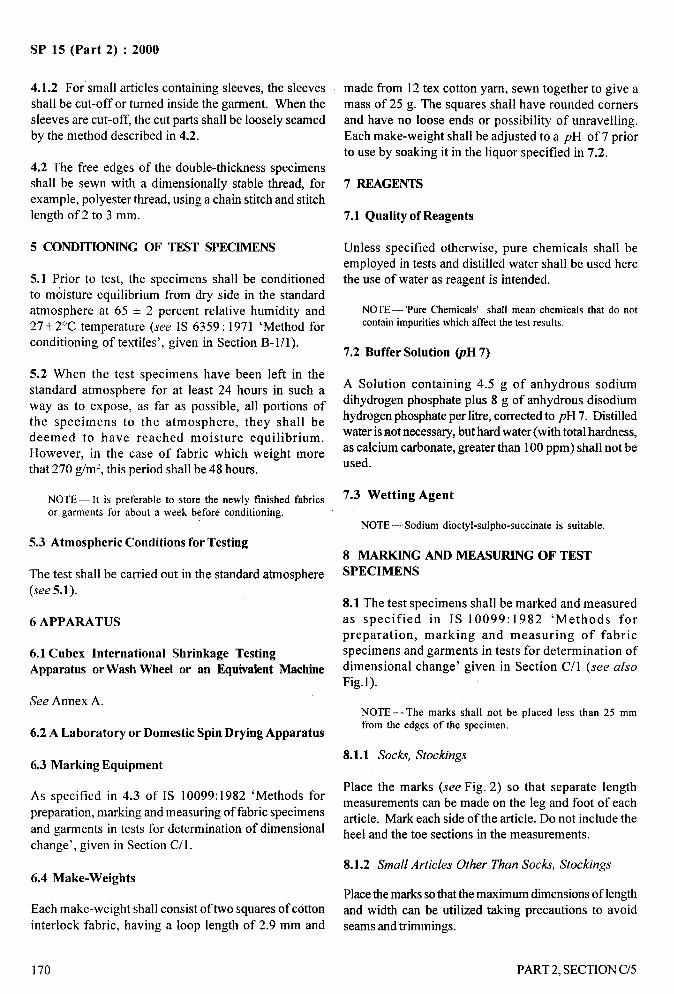
.—-
SP 15 (Part 2) :2000
.-.,4.1.2 For small articles containing sleeves, the sleevesshall be cut-off or turned inside the garment. When thesleeves are cut-off, the cut parts shall be loosely seamedby the method described in 4.2.
made from 12 tex cotton yarn, sewn together to give amass of 25 g. The squares shall have rounded cornersand have no loose ends or possibility of unraveling.Each make-weight shall be adjusted to a pH of 7 priorto use by soaking it in the liquor specified in 7.2.
4.2 The free edges of the double-thickness specimensshall be sewn with a dimensionally stable thread, forexample, polyester thread, using a chain stitch and stitchlength of 2 to 3 mm.
7 REAGENTS
7.1 Quality of Reagents
5 CONDITIONING OF TEST SPECIMENS Unless specified otherwise, pure chemicals shall beemployed in tests and distilled water shall be used herethe use of water as reagent is intended.5.1 Prior to test, the specimens shall be conditioned
to moisture equilibrium from dry side in the standardatmosphere at 65 + 2 percent relative humidity and27+ 2°C temperature (see IS 6359:1971 ‘Method for
conditioning of textiles’, given in Section B-1/1).
NOTE — ‘Pure Chemicals’ shall mean chemicals that do notcontain impurities which affect the test results.
7.2 Buffer Solution @H 7)
5.2 When the test specimens have been left in thestandard atmosphere for at least 24 hours in such away as to expose, as far as possible, all portions ofthe specimens to the atmosphere, they shall bedeemed to have reached moisture equilibrium.However, in the case of fabric which weight morethat 270 g/m2, this period shall be 48 hours.
A Solution containing 4.5 g of anhydrous sodiumdihydrogen phosphate plus 8 g of anhydrous disodiumhydrogen phosphate per Iitre, corrected to pH 7. Distilledwater is not necessary, but hard water (with total hardness,as calcium carbonate, greater than 100 ppm) shall not beused.
7.3 Wetting AgentNOTE— lt is preferable to store the newly finished fabricsor garments for about a week before conditioning.
NOTE— Sodium dioctyl-sulpho-succinate is suitable.
5.3 Atmospheric Conditions for Testing8 MARKING AND MEASURING OF TESTSPECIMENSThe test shall be carried out in the standard atmosphere
(see 5.1). ‘-),8.1 The test specimens shall be marked and measuredas specified in IS 10099:1982 ‘Methods forpreparation, marking and measuring of fabricspecimens and garments in tests for determination ofdimensional change’ given in Section C/l (see alsoFig. 1).
6 APPARATUS
6.1 Cubex International Shrinkage TestingApparatus or Wash Wheel or an Equivalent Machine
See Annex A.NOTE—The marks shall not be placed less than 25 mmfrom the edges of the specimen.
6.2 A Laboratory or Domestic Spin Drying Apparatus
8.1.1 Socks, Stockings6.3 Marking Equipment
Place the marks (see Fig. 2) so that separate lengthmeasurements can be made on the leg and foot of eacharticle. Mark each side of the article. Do not include theheel and the toe sections in the measurements.
As specified in 4.3 of IS 10099:1982 ‘Methods for
preparation, marking and measuring of fabric specimens
and garments in tests for determination of dimensional
change’, given in Section C/l.
8.1.2 Small Articles Other Than Socks, Stockings6.4 Make-Weights
Place the marks so that the maximum dimensions of lengthand width can be utilized taking precautions to avoidseams and trimmings.
Each make-weight shall consist of two squares of cotton
interlock fabric, having a loop length of 2.9 mm and
170 PART2, SECTION C/5
/
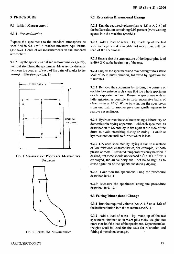
. 4.
9 PROCEDURE
9.1 Initial Measurement
9.1.1 Preconditioning
Expose the specimens to the standard atmosphere asspecified in 5.1 until it reaches moisture equilibrium(see 5.2). Conduct all measurements in the standardatmosphere.
9.1.2 Lay the specimens flat and remove wrinkles gently,without stretching the specimens. Measure the distance
between the centres of each of the pairs of marks to thenearest millimetre (see Fig. 1). -
kWIDTH 3DOm m ~
x—
\x—
Ix—
FIG. 1 MEASUREMENTPOINTSSPECIMEN
1LENGTH
400mm
FORMARXINGTHE
FIG. 2 POINTSFORMEASUREMENT
PART 2, SECTION C/5
SP 15 (Part 2) :2000
9.2 Relaxation Dimensional Change
9.2.1 Run the required volume (see A-1.5 or A-2.6) ofthe buffer solution containing 0.05 percent (m/v) wettingagents into the machine (see 6.1).
9.2.2 Add a load of mass 1 kg, made up of the testspecimens plus make-weights not more than half theload of the specimens.
9.2.3 Ensure that the temperature of the liquor plus loadis 40 & 2°C at the beginning of the test.
9.2.4 Subject the specimens and make-weights to a staticsoak of 15 minutes duration, followed by agitation for5 minutes.
9.2.5 Remove the specimens by folding the comers ofeach to the centre in such a way that the whole specimencan be supported in hand. Rinse the specimens with aslittle agitation as possible in three successive baths ofclean water at 40”C. While transferring the specimensfrom one bath to another give one gentle squeeze toremove excess liquor.
9.2.6 Hydroextract the specimens using a laboratory or
domestic spin drying apparatus. Fold each specimen asdescribed in 9.2.5 and lay it flat against the side of thedrum to avoid stretching during spinning. Continuehydroextraction until no Iiu-ther water is lost.
9.2.7 Dry each specimen by laying it flat on a surfaceof low frictional characteristics, for example, smoothplastic or metal. Elevated temperatures maybe used ifdesired, but these should not exceed 55”C. If air flow isemployed, the air velocity shall not be so high as tocause agitation of the specimens during drying.
9.2.8 Condition the specimens using the proceduredescribed in 9.1.1.
9.2.9 Measure the specimens using the proceduredescribed in 9.1.2.
9.3 Felting Dimensional Change
9.3.1 Run the required volume (see A-1.5 or A-2.6) ofthe buffer solution into the machine (see 6.1).
9.3.2 Add a load of mass 1 kg, made up of the testspecimens obtained as in 9.2.9 plus make-weights notmore than halfthe load of the specimens. Separate make-weights shall be used for the tests for relaxation andfelting dimensional changes.
171
-— -—
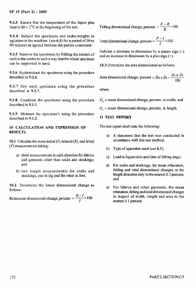
SP 15 (Part 2) :2000
9.3.3 Ensure that the temperature of the liquor plus F–i?xlooload is 40 + 2°C at the beginning of the test. Felting dimensional change, percent = ~
9.3.4 Subject the specimens and make-weights toagitation in the machine (see 6.1) for a period of 30 to
F–zxlooTotal dimensional change, percent = ~
60 minutes as agreed between the parties concerned.
9.3.5 Remove the specimens by folding the corners ofIndicate a decrease in dimension by a minus sign (–)and an increase in dimension by a plus sign (+).
each to the centre in such a way that the whole specimencan be supported in hand. 10.3 Determine the area dimensional as follows :
9.3.6 Hydroextract the specimens using the procedureD. X DL
described in 9.2.6. Area dimensional change, percent = D.+ DL–100
9.3.7 Dry each specimen using the proceduredescribed in 9.2.7. where
9.3.8 Condition the specimens using the procedure DW= mean dimensional change, percent, in width, and
described in 9.1.1.D~ = mean dimensional change, percent, in length.
9.3.9 Measure the specimen’s using the proceduredescribed in 9.1.2. 11 TEST REPORT
10 CALCULATION AND EXPRESSION OF The test report shall state the following:
RESULTSa)
10.1 Calculate the mean initial (Z),relaxed (R), and felted
(F’) measurements taking:b)
a)
b)
three measurements in each direction for fabrics c)and garments other than socks and stockings;and d)
two length measurements for socks andstockings, one in leg and the other in foot.
10.2 Determine the linear dimensional change asfollows:
e)
R-zxlooRelaxation dimensional change, percent = ~
A statement that the test was conducted inaccordance with this test method;
Type of apparatus used (see 6.1);
Load to liquor ratio and time of felting stage;
For socks and stockings, the mean relaxation,felting and total dimensional changes in thelength direction only to the nearest 0.1 percent;and
For fabrics and other garments, the meanrelaxation, felting and total dimensional changesin respect of width, length and area to thenearest 0.1 percent.
172
/
PART2, SECTION C/5
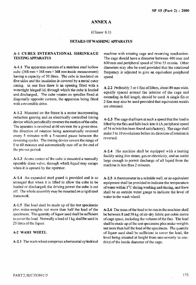
..-SP 15 (Part 2) :2000
ANNEX A
(Clause 6.1)
DETAILS OF WASHING APPARATUS
A-1 CUBEX INTERNATIONAL SHRINKAGETESTING APPARATUS
A-1.1 The apparatus consists of a stainless steel hollowcube (368 mm x 368 mm x 368 mm inside measurement)having a capacity of 50 litres. The cube is insulated onfive sides and the insulation is covered by a metal outercasing. In one face there is an opening fitted with awatertight hinged lid, through which the cube is loadedand discharged,. The cube rotates on spindles fixed atdiagonally opposite comers, the apparatus being fittedwith a reversible drive.
A-1.2 Mounted on the frame is a motor incorporatingreduction gearing and an electrically controlled timingdevice which periodically reverses the motion of the cube.The aparatus is revolved at 60 rev/rein for a given time,the direction of rotation being automatically reversedevery 5 minutes with a 5-second pause between thereversing cycles. The timing device covers the range of
O to 60 minutes and automatically cuts off at the end ofthe pre-set period.
A-1.3 At one corner of the cube is mounted a manuallyoperable drain valve, through which liquid may escapewhen it is opened by the operator.
A-1.4 An expanded steel guard is provided and is soarranged that when it is lified to allow the cube to beloaded or discharged, the driving power the cube is cutoff. The whole assembly may be mounted on a rigid steelframework.
A-1.5 The load shall be made up of the test specimensplus make-weights not more than half the load of thespecimens. The quantity of liquor used shall be sufficientto cover the load. Normally a load of 1 kg shall be used in25 litres of the liquor.
A-2 WASH WHEEL
A-2.1 The wash wheel comprises a horizontal cylindrical
machine with rotating cage and reversing mechanism.The cage should have a diameter between 400 mm and
600 mm and peripheral speed of 50 to 55 m/min. Otherdiameters may also be used provided that the rotational
frequency is adjusted to give an equivalent peripheral
speed.
A-2.2 Preferably 3 or 4 fins of lifters, about 80 mm wide,equally spaced around the interior of the cage and
extending its full length, should be used. A single fm or2 fins may also be used provided that equivalent resultsare obtained.
A-2.3 The cage shall turn at such a speed that the load is
lifted by the fms and falls back into it (A peripheral speed
of 54 m/min has been found satisfactory). The cage shallmake 5 to 10 revolutions before its direction of rotation is
reversed.
A-2.4 The machine shall be equipped with a heating
facility using live steam, gas or electricity, and an outlet
large enough to permit discharge of all liquid from the
machine in less than 2 minutes.
A-2.5 A thermometer in a suitable well, or an equivalent
equipment shall be provided to indicate the temperatureof water within 1‘C during washing and rinsing, and thereshall be an outside water gauge to indicate the level of
water in the wash wheel.
A-2.6 The mass of the load to be run in the machine shallbe between 8 and 50 kg of air-dry fabric per cubic metre
of cage space, including the volume of the fins. The loadshall be made up of the test specimens plus make-weightsnot more than half the load of the specimens. The quantityof liquor used shall be sufficient to cover the load, the
level being situated at height from one-seventy to one-third of the inside diameter of the cage.
—-.-:
1:..--“%
‘1,,
J!;
II
I
PART2. SECTION C/5 173
4—-
SP 15 (Part 2) :2000
DETERMINATION OF DIMENSIONAL CHANGES ON WASHING
OF FABRICS WOVEN FROM RAYON AND SYNTHETIC FIBRES
(Source : IS 1299: 1984)
The dimensions of fabrics woven from rayon and synthetic fibres are liable to change on soaking in water. Theirdimensional instability is liable to be higher when washed with soap. As the goods made out of these materials areusually washed with soap, their dimensional change behaviour is of obvious interest to the consumer.
1 SCOPE
1.1 It prescribes a method for determination of
dimensional changes on washing of fabrics woven fromrayon and synthetic fibres or their mixtures.
1.2 The method is intended only for the assessment ofdimensional changes undergone by woven fabricssubjected to single mechanical washing. When it isdesired to determine the amount of progressivedimensional changes, the test specimens should bewashed repeatedly and the amount of dimensional
changes in the washed specimens and the number oftesting cycles to which the specimens have beensubjected indicated clearly.
2 SAMPLING
2.1 Lot
The quantity of the fabric purporting to be of one definitetype and quality, delivered to a buyer against one despatchnote shall constitute a lot.
2.2 Samples for test shall be selected so as to berepresentative of the lot. Samples drawn in compliancewith the material specification or as agreed to betweenthe buyer and the seller shall beheld to be representativeof the lot.
3 TEST SPECIMENS
3.1 From the samples under test draw 3 test specimens,each of length 650 mm and of fill width, taking care that
a) the specimens are not drawn from within 1 mof either end of the piece,
b) no two specimens are drawn from the samepiece, and
c) the specimens are cut and not torn from thepiece.
3.2 The free edges of the specimens shall be sewn with adimensionally stable thread, for example, polyester thread,using a chain stitch and stitch length of 2 to 3 mm.
174
4 CONDITIONING OF TEST SPECIMENS
4.1 Prior to test, the test specimens shall be conditionedto moisture equilibrium fi-om dry side in the standard
atmosphere at 65+2 percent relative humidity and27+ 2°C temperature (see 1S 6359:1971 ‘Method forconditioning of textiles’, given in Section B-1/1).
4.2 When the test specimens have been left in such an
atmosphere for 24 hours in such a way as to expose, asfar as possible, all portions or the specimens to the
atmosphere, they shall be deemed to have reachedmoisture equilibrium. However, in the case of fabricswhich weigh more than 270 g/m2, this period shall be 48hours.
NOTE — It is preferable to store the newly finished fabricsfor about a week before conditioning.
4.3 Atmospheric Conditions for Testing
The test shall be carried out in the standard atmosphere(see 4.1).
5 APPARATUS
5.1 Cubex International Shrinkage Testing Apparatusor Wash Wheel or an Equivalent Machine
See Annex A.
5.2 Extractor
A laundry-type centrifugal extractor with perforatedbasket, capable of adjusting the moisture retention ofthe fabric to a range between 50 and 100 percent (m/m)based on the air-dry mass of the fabric.
NOTES1 Any other apparatusthat will give equivalent results withoutfabric distortion for example, rubber roll wringer which couldpass the specimen through the rolls along a diagonal linewithout altering its dimensions may also be used.
2 Heavier fabrics of tight construction require a high moistureretention to ensure removal of wrinkles during pressing.
PART2, SECTION C/6
‘\,,,,, “.
.4
5.3 Pressing Equipment
A flat bed press capable of pressing a specimen ofsize 600 mm x 600 mm and of providing a minimumpressure of 3 kPa. The temperature of the press shallbe 150 + 15°C.
5.4 Marking Equipment
As specified in IS 10099:1982 ‘Methods forpreparation, marking and measuring of fabricspecimens and garments in tests for determination ofdimensional change’, given in Section C/l.
5.5 Make-Weights
The make-weights shall consist of fabric similar to thatof the test specimens. Each make-weight shall be adjustedto a pH of 7 prior to use.
6 REAGENT
6.1 Soap Solution
Prepare a stock solution by dissolving 0.5 kg of soap in4 litres of hot water. When cooled, this solution formsa thick jelly which may be used as required. From thisstock solution, prepare a soap solution for the testcontaining 5 g/1 of soap on dry mass basis.
Soap meeting the following composition (based upondry mass) is satisfactory:
Free alkali calculated as Na2CO~, Max 0.3 percent
Free alkali calculated as NaOH, Max 0.1 percent
Combined fatty acids calculated 85 percentas Na salt, &fin
Titre of mixed fatty acids prepared 39°cfrom the soap, Max
Iodine value of fatty acids, Max 50
NOTE— Information regarding availability of the soap ofabove composition may be had from BIS, , .,
7 PREPARATION, MARKING ANDMEASURING OF TEST SPECIMENS
7.1 The test specimens shall be prepared, marked andmeasured as specified in IS 10099:1982 ‘Methods forpreparation, marking and measuring of fabric specimensand garments in tests for determination of dimensionalchange’, given in Section C/l.
PART2. SECTION C/6
SP 15 (Part 2) :2000
8 PROCEDURE
8.1 Initial Measurement
Expose the specimens to the standard atmosphere asspecified in 4.1 until they reach moisture equilibrium(see 4.2). Measure the distance between the centres ofeach of the pairs of marks to the nearest milhmetre usingthe procedure described in IS 10099:1982 ‘Methodsfor preparation, marking and measuring of fabricspecimens and garments in tests for determination ofdimensional change’, given in Section C/l.
8.2 Washing and Rinsing
8.2.1 Run water into the machine (see 5.1) at thetemperature such that the machine will heat the liquor to50 ‘C within 10 minutes, maximum, and fill to the properlevel for washing (see A-1.5 or A-2.6) within 4 minutes.
8.2.2 Add a load of mass 1 kg, made up of the testspecimens plus made-weights not more than half the loadof the specimens,
8.2.3 Add sufficient soap (6.1) to give good runningsuds. If more than 5 gll of soap is used, the amount andreasons for this shall be reported [see 11.1 (c)]. Thetemperature shall be maintained at not less than 45°C.
8.2.4 When the machine has run for 45 minutes, timedfrom the start of the test drain offthe soap solution quickly
and fill the machine with water to the proper level forrinsing. Raise the temperature to 50°C within 10 miunutesmaximum.
8.2.5 When the machine has run for another 5 minutes,drain off the water, fill again and heat to 50”C as before.
8.2.6 At the end of the next 5 minutes, drain off thewater quickly. Allow the machine to run without furtheradditions for 5 minutes more. Stop the machine.
8.3 Extraction
Remove the specimens from the machine by folding thecorners of each to the centre in such away that the wholespecimen can be supported in hand. Lay each specimenflat against the side of the perforated basket of theextractor to avoid streching during rotation and extractthe excess water (5.2).
8.4 Pressing
Press each specimen taking care to ensure that it issmoothened. Without stretching, remove wrinkles
175
/
SP 15 (Part 2) :2000
r ----(
before pressing. Continue this operation until sufficientmoisture has been extracted from the fabric to ensureconditioning fi-om the dry side.
8.5 Final Measurement
Allow the pressed specimen to cool, condition in the
standard atmosphere and measure the distance betweenthe centres of the markings to the nearest millimetre(see IS 10099:1982 ‘Methods for preparation, markingand measuring of fabric specimens and garments in testsfor determination of dimensional change’, given inSection C/l ).
9.2 Determine the area dimensional change as follows:
Area dimensional change, percent =
D.+DL.=
where
DW= mean dimensional change, percent in width; and
D~ = mean dimensional change, percent in length.
10 REPORT
9 CALCULATION AND EXPRESSION OFRESULTS a)
9.1 Calculate the dimensional changes in the length and b)width directions separately by the following formula:
c)F- I
Dimensional change, percent = ~ x 100
whered)
F = final measurement (see 8.5), and
1 = initial measurement (see 8.1). e)
Express as percentages of the original value to the nearest0.5 percent, using a minus sign (–) to indicate shrinkage f)
and a plus sign (+) to indicate elongation. Calculate themean value and the range of the dimensional change for g)each set of replicates.
10.1 The test report shall include the following particulars:
iA,’ -:
A statement that the test was conducted inaccordance with this test method;
Type of apparatus used (see 5.1);
Concentration of the soap solution used (statethe reasons for using more than 5 g/1 of soapwhen this amount is exceeded);
Number oftesting cycles to which the specimenswere subjected;
Dimensional changes in each specimen in thelength and width directions and in area;
Mean dimensional changes in the replicates, inthe length and width directions and in area; and
Range of individual dimensional change values.
176
;Ifi
PART2, SECTION C/6
SP 15 (Part 2) :2000
m“”
I,.
ANNEX A =
(Clause 5.1)
DETAILS OF WASHING APPARATUS,<,. ...-.?
J.,,,~
A-1 CUBEX INTERNATIONAL SHRINKAGETESTING APPARATUS
A-1. 1 The apparatus consists of a stainless steel hollow
cube (368 mm x 368 mm x 368 mm inside measurement)having a capacity of 50 litres. The cube is insulated on
five sides and the insulation is covered by a metal outercasing. [n one face there is an opening fitted with awatertight hinged lid, through which the cube is loadedand discharged. The cube rotates on spindles fixed atdiagonally opposite corners, the apparatus being fittedwith a reversible drive.
A-1.2 Mounted on the frame is a motor incorporatingreduction gearing and an electrically controlled timingdevice which periodically reverses the motion of the cube.The apparatus is revolved at 60 rev/rein for given time,the direction of rotation being automatically reversedevery 5 minutes with a 5-second pause between thereversing cycles. The timing device covers the range ofOto 60 minutes and automatically cuts off at the end ofthe pre-set period.
A-1.3 At one corner of the cube is mounted a manually
operable drain valve, through which liquid may escapewhen it is opened by the operator.
A-1.4 An expanded steel guard is provided and is soarranged that when it is lifted to allow the cube to beloaded or discharged, the driving power to the cube is
cut off. The whole assembly may be mounted on a rigidsteel framework.
A-1.5 The load shall be made up of the test specimensplus make weights not more than half the load of thespecimens. The quantity of liquor used shall be sufficientto cover the load. Normally a load of 1kg shall be used in25 Iitres of the liquor.
A-2 WASH WHEEL
A-2. 1 The wash wheel comprises horizontal cylindrical
machine with rotating cage and reversing mechanism.The cage should have a diameter between 400 and 600mm and peripheral speed of 50 to 55 m/min. Otherdiameters may also be used provided that the rotationalfrequency is adjusted to give an equivalent peripheralspeed.
A-2.2 Preferably 3 or 4 fins or lifters, about 8 cm wide,
equally spaced around the interior of the cage andextending its full length, should be used. A single fin or2 tins may also be used provided that equivalent resultsare obtained.
A-2.3 The cage shall turn at such a speed that the load islifted by the fins and falls back into it (A peripheral
speed of 54 m/min has been found satisfactory). Thecage shall make 5 to 10 revolutions before its direction ofrotation is reversed.
A-2.4 The machine shall be equipped with a heatingfacility, using live steam, gas or electricity, and an outletlarge enough to permit discharge of all liquid from the
machine in less than 2 minutes.
A-2.5 A thermometer in a suitable well, or an equivalent i.
equipment, shall be provided to indicate the temperatureof water within 1°C during washing and rinsing, andthere shall be an outside water gauge to indicate thelevel of water in the wash wheel.
A-2.6 The mass of the load to be run in the machineshall be between 8 and 50 kg of air-dry fabric per cubicmetre of cage space, including the volume of the fins.The load shall be made up of the test specimens plusmake-weights not more than half the load of thespecimens. The quantity of liquor used shall be sufficientto cover the load, the level being situated at a heightfrom one-seventh to one-third of the inside diameter ofthe cage.
PART 2, SECTION C/6
/
I77 I
.—
SP 15 (Part 2) :2000
DETERMINATION OF DIMENSIONAL CHANGES OF
SILK FABRICS ON WASHING
(Source : IS 3561: 1989)
Merely on soaking in water the dimensions of fabrics woven from silk are liable to change. Their dimensionalinstability is liable to be higher when washed with soap. As fabrics made out of silk are washed with mild soap, theirdimensional stability is of obvious interest to the consumer.
1 SCOPE
1.1 It prescribes a method for determination ofdimensional changes on washing of natural silkfabrics.
1.2 The method is intended only for theassessment of dimensional changes undergone byfabrics subjected to a single washing treatment.When it is desired to determine the amount ofprogressive dimensional changes, the testspecimens should be washed repeatedly and theamount of dimensional changes of the washedspecimens and the number of washing cycles towhich the specimen has been subjected, beindicated clearly in the report.
2 PRINCIPLE
The specimens, after conditioning, is measured, washed,dried under prescribed conditions, reconditioned andremeasured. The dimensional changes obtained arecalculated from the means of the original and finaldimensions in the length ways andlor widthwaysdirection.
3 SAMPLING
Sample from the lot shall be drawn so as to berepresentative of the lot. Sample drawn in accordancewith the relevant material specification or as agreed tobetween the buyer and the seller shall be held to berepresentative of the lot.
4 APPARATUS
4.1 Water Tight Tray or Container
Approximately 100 ml deep and of sufficient area tocontain the specimen horizontally without folding. It shallbe provided with a glass plate for covering and with’suitable draining arrangement.
4.2 Steel Rule, graduated in mm.
178
4.3 Means of Marking Reference Points, asspecified in 4.3 of IS 10099 : 1982 ‘Methods forpreparation, marking and measuring of fabricspecimens and garments in tests for determination ofdimensional change’ given in Section C/1.
4.4 Two Pieces of Plate Glass, each measuring at least600 mm x 600 mm.
5 REAGENTS
5.1 Quality of Reagents
Unless otherwise specified pure chemicals and distilledwater shall be used wherever the use of water as a reagentis intended.
NOTE—“’Purechemicals’shallmeaochemicalsthatdonotcontainimpuritieswhichaffectthe test results.
5.2 Soap Solution
Containing 5 g of soap per Iitre of the composition asspecified in Annex A.
6 ATMOSPHERE FOR CONDITIONING ANDTESTING
6.1 Prior to test, the test specimens shall be conditionedto mositure equilibrium from the dry side in a standardatmosphere at 65*2 percent relative humidity and27A 2°C temperature (see IS 6359:1971 ‘Method of
conditioning of textiles’, given in Section B-1/1).
6.2 When the test specimens have been left in suchan atmosphere for 24 hours in such a way as toexpose, as far as possible, all portions of thespecimens to the atmosphere, they shall be deemedto have reached moisture equilibrium. However, incase of fabrics which weigh more than 270 g/m3,this period shall be 48 hours.
NOTE— It is preferableto store the newly finishedt’abricsforabout a week before conditioning.
PART2, SECTION C/7
1
I
,*—-
SP 15 (Part 2) :2000
6.3 The testing shall be carried out in the standardatmosphere (see 6.2).
7 TEST SPECIMENS
Draw at least one test specimen from each piece of widefabrics measuring not less than 500 mm x 500 mm withedges parallel to the length and width of fabric and atleast three specimens from each piece of narrow fabricsmeasuring 500 mm in length and of full width. Do nottake any specimen within 1 m of either end of the piece.In case of wide fabrics, do not take specimens with
selvedges. For knitted fabrics, make up the specimensin double thickness, sewing the free edges togetherwith dimensionally stable thread. When fabrics withfancy weave structures are being tested, ensure as faras possible that exact number of repeats are taken ineach test specimen.
NOTE — The specimen should be cut and not torn from thefabric.
8 PROCEDURE
8.1 Marking and Measuring of Test Specimens beforeWashing
Mark and measure the distance between referencepoints in the test specimens previously conditioned inthe standard atmosphere (see 6.2) as prescribed in1S 10099: 1982. ‘Methods for preparation, markingand measuring of fabric specimens and garments intests for determination of dimensional change’, givenin Section C/l.
8.2 Washing of Test Specimens
8.2.1 Lay one test specimen flat after removing all creasesand wrinkles by hand for one hour in the watertight traycontaining 5 g/1 of soap solution at 50”C. Ensure thatthe depth of liquid above the specimen is at least 25 mm.If necessary, keep the specimen submerged, for example,by use of small weight-pieces, ensuring that these areassmall as possible.
8.2.2 After I hour, pour off the liquid and wash thespecimen first with water at 50°C for 20 minutes andthen with cold water for 5 minutes while kept flat.Remove the specimen without distortion from the trayand place it flat on a towel. Ensure that the specimen isnot stretched during handling. The most convenientmethod is to fold the corners to the centre so that the
whole specimen is supported when lifted on to thetowel. Remove excess moisture by lightly pressinganother towel on top of the specimen.
8.2.3 Lay the specimen on a smooth flat surface andallow it to dry at room temperature. Condition thespecimen in the standard atmosphere (see 6.1) tomoisture equilibrium from the dry side and remeasurethe distances between corresponding reference pointsto the nearest mm as prescribed in 8.1.
8.3 Repeat the procedure from 8.1 to 8.2.3 with theremaining test specimens.
9 CALCULATION AND EXPRESSION OFRESULTS
9.1 Calculate the mean of the original dimensions andthe mean of the final dimensions for each test specimenin each direction separately to the nearest millimetre.
Calculate separately the percentage dimensional changefor each specimen in each direction (Iengthways andwidthways) by the formula:
Dimensional change, percent =loo(b–a)
a
where
a= mean original dimension before treatmentfor each test specimen, and
b= mean final dimension after treatment foreach test specimen.
9.2 Calculate the mean of the dimensional changes of allthe specimens, separately in each direction.
9.3 Express the mean dimensional change percent in
each direction to the nearest 0.1 percent.
10 REPORT
The report shall include the following information:
a) Whether the specimens were from wide ofnarrow fabrics and the number of specimenstested from each piece in the test sample;
b) The mean dimensional change, percent, in thelengthways and widthways directions for widefabrics, and in the lengthways directions fornarrow fabrics; and
c) Indicate a decrease in dimension by a minussign and an increase by a plus sign.
—---/
)
PART2, SECTION C/7 179
...-SP 15 (Part 2) :2000
180
a)
b)
c)
d)
e)
f)
g)
h)
.0
k)
ANNEX A
(Clause 5.2)
COMPOSITION OF SOAP
Soap shall be free from optical brightening agents
Moisture regain, percent, Max
Titre of fatty acids, “C, Max
Total fatty matter, percent by mass, A4in
Rosin acids, percent by massof total fatty matter, Max
Unsaponified fatty matter,percent by mass, Max
Free caustic alkali,
percent by mass, Max
Matter insoluble in alcohol,percent by mass, Max
Glycerol percent bymass, Max
Hexabromide test
(on fatty acids)
4
25
80
3.0
0.5
0.05
2.0
1.5
Negative
PART 2. SECTION C/7
{
‘r+ ..
.-
-+
i\!, ‘%
SP 15 (Part 2) :2000
DETERMINATION OF ABSORBENCY OF
ABSORBENT TEXTILE MATERIALS
(SOWCe : IS 2369: 1967)
Absorbent textile materials, such as cotton gauze and cotton wool, are used mostly for surgical purposes. Acotton material of definite absorbency is necessary for use in surgical and other purposes. A textile material,
whose absorbency in terms of seconds is less than 10, is considered as highly absorbent material. it is hoped that
the revised standard would be helpful in determining the absorbency of absorbent textile materials.
1 SCOPE
This standard prescribes a method for determination ofabsorbency of absorbent textile materials, such as cotton
gauze and cotton wool.
2 PRINCIPLE
The test specimen of specific area or specific volume isplaced on the surface of water. The time taken by the
specimen to absorb water and sink in it completely is a
measure of the absorbency of the test specimen. The
shorter the time taken by the specimen to sink in water
completely, the greater is its absorbency.
3 SAMPLING
3.1 Lot
The quantity of rolls or bundles of absorbent material(such as cotton gauze and cotton wool) delivered to the
buyer against a despatch note shall constitute the lot.
3.2 Unless otherwise agreed to between the buyer andthe seller the number of rolls or bundles to be selected
at random from the lot shall be as given below:
Lot size Sample Size
(1) (2)
up to 100 4
101’’ 150 5
151’’ 300 7
301 “ 500 10
3.3 The rolls or bundles selected according to 3.2 shall
constitute the test sample.
PART 2, SECTION C/8
4 CONDITIONING OF TEST SPECIMENS AND
ATMOSPHERIC CONDITIONS FOR TESTING
4.1 Conditioning for Test Specimens
Prior to test, the test specimens shall preferably beconditioned to moisture equilibrium in a standardatmosphere at 65 * 2 percent relative humidity and27* 2°C temperature (see Section B-l/l).
4.1.1 When the test specimens have been left in such anatmosphere for 24 hours in such a way as to expose, asfar as possible, all portions of the specimens to theatmosphere, they shall be deemed to have reachedmoisture equilibrium.
4.2 Atmospheric Conditions for Testing
The test shall preferably be carried out in the standardatmospheric conditions (see 4.1 ).
\
5 APPARATUS
5.1 Wide-Bore GlassFig. 1).
5.2 Glass Plunger,(see Fig. 1).
5.3 Glass Trough,20cmx 15cm x 50cm.
Tube, open as both ends (see
solid or closed at the bottom
of suitable size, preferably
5.4 Retort Stand, with a clamp.
5.5 Stop -Watch, reading correct to 0.1 second.
5.6 Two Glass Plates, 10 cm x 10 cm and 0.75 cmthickness.
5.7 A Pair or Forceps
181
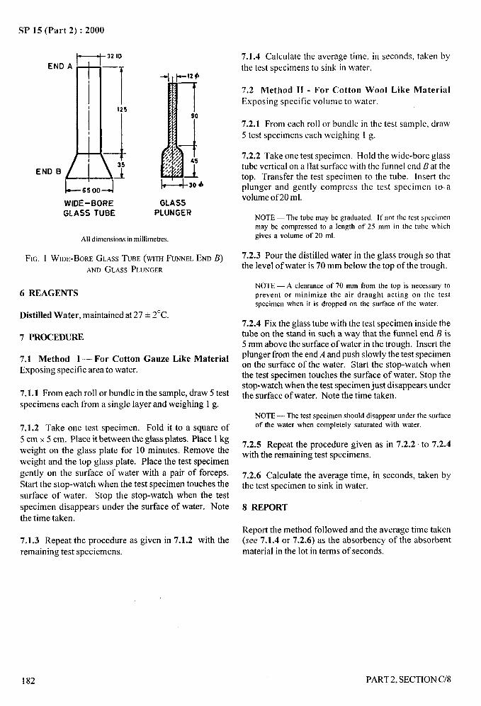
SP 15 (Part 2) :2000
END A
END B /
t(
I
1
32 ID
—.A
7.1.4 Calculate the average time, inthe test specimens to sink in water.
125
1 -1--bL-650DJ5WIDE-BORE GLASS
GLASS TUBE PLUNGER
Alldimensionsin millimetres.
FIG. 1 WIDE-BOREGLASSTUBE(wrm FUNNELEm B)ANDGLASSPLUNGER
6 REAGENTS
Distilled Water, maintained at 27 + 2“C.
7 PROCEDURE
7.1 Method 1— For Cotton Gauze Like MaterialExposing specific area to water.
7.1.1 From each roll or bundle in the sample, draw 5 testspecimens each from a single layer and weighing 1 g.
7.1.2 Take one test specimen. Fold it to a square of
5 cm x 5 cm. Place it between the glass plates. Place 1 kgweight on the glass plate for 10 minutes. Remove theweight and the top glass plate. Place the test specimengently on the surface of water with a pair of forceps.
Start the stop-watch when the test specimen touches thesurface of water. Stop the stop-watch when the testspecimen disappears under the surface of water. Notethe time taken.
7.1.3 Repeat the procedure as given in 7.1.2 with theremaining test specimens.
seconds, taken by
7.2 Method 11- For Cotton Wool Like MaterialExposing specific volume to water.
7.2.1 From each roll or bundle in the test sample, draw5 test specimens each weighing 1 g.
7.2.2 Take one test specimen. Hold the wide-bore glasstube vertical on a flat surface with the funnel end B at thetop. Transfer the test specimen to the tube. Insert theplunger and gently compress the test specimen to- avolume of20 ml.
NOTE — The tube may be graduated. It’not the test specimenmay be compressed to a length of 25 mm in the tube whichgives a volume of 20 ml.
7.2.3 Pour the distilled water in the glass trough so thatthe level of water is 70 mm below the top of the trough.
NOTE— A clearance of 70 mm from the top is necessary toprevent or minimize the air draught acting on the testspecimen when it is dropped on the surface of the water.
7.2.4 Fix the glass tube with the test specimen inside thetube on the stand in such a way that the funnel end B is5 mm above the surface of water in the trough. Insert theplunger from the end A and push slowly the test specimenon the surface of the water. Start the stop-watch whenthe test specimen touches the surface of water. Stop thestop-watch when the test specimen just disappears underthe surface of water. Note the time taken.
NOTE— The test specimen should disappear under the surfaceof the water when completely saturated with water.
7,2.5 Repeat the procedure given as in 7.2.2 to 7.2.4with the remaining test specimens.
7.2.6 Calculate the average time, in seconds, taken bythe test specimen to sink in water.
8 REPORT
Report the method followed and the average time taken(see 7.1.4 or 7.2.6) as the absorbency of the absorbentmaterial in the lot in terms of seconds.
—-.-,
‘i,,,,. .
182 PART 2, SECTION C/8
tA
-
_. ...-SP 15 (Part 2) :2000
I
P
I
I
11=.4’
t
I
DETERMINATION OF NETTABILITY OF COTTON FABRICS : –.4;
(Source : IS 2349:1963)
~
v, ,,PT. :
In the cotton textile industry the fabrics undergo treatment of scouring prior to bleaching and other finishing treatments...
.),~
By scouring treatment the cotton material is made more absorbent. Nettability is a very important property of alltextile materials. Bleaching, dyeing, and finishing of textiles are dependent among others on the nettability of thematerial. It is expected that the method of test prescribed in this standard would be of use for determining thenettability of cotton textile materials.
1 SCOPE
It prescribes a method for the determination of nettabilityof cotton fabrics. This method is also applicable forassessing the efficiency of scouring.
2 PRINCIPLE
A drop of water is allowed to fall on the test specimen.A lamp is suitably placed so that the image of the lamp isseen on the drop. The time taken for the image of thelamp to just ciisappear at the edge of the drop is noted.This time is a measure of the nettability of the sampleunder test.
NOTE — ‘lhe longer the time taken, the lower is thenettability.
3 SAMPLING
3.1 Sample to determine nettability of a lot of the material
shall be selected so as to be representative of the lot.
3.2 Sample drawn in accordance with an agreement
between the buyer and the seller to determine the
nettability of a lot of the material shall be held to be
representative of the lot.
3.3 In case of dispute as to whether the material in a lot
conforms to the standard or not and there being no agreedmethod of drawing its representative sample, the sampleselected to represent the lot shall consist of fabric frombales constituting the early, middle and late parts of thelot in order of time of delivery, or in the case of singledelivery, in order of serial numbers of bales. The fabricselected shall be not less than 1 percent nor more than 10percent of the lot by weight and shall be selected frombales constituting not less than 10 percent nor more than50 percent of the lot. The fabric so drawn shall constitutethe test sample.
4 ATMOSPHERIC CONDITIONS FOR TESTING
4.1 Unless otherwise provided for in an agreementbetween the buyer and the seller, all tests shall be carried
PART2. SECTION C/9
in a standard atmosphere at 65 + 2 percent relative
humidity and 27+ 2°C temperature or within a period of
5 minutes of the removal of the test spcimen from thestandard atmosphere.
4.2 The test shall be carried out in standard atmosphere(see 4.1).
5 CONDITIONING OF TEST SPECIMENS
5.1 Prior to evaluation, the test sample (or the testspecimens drawn therefrom) shall be conditioned tomoisture equilibrium (see 4.1 ), unless otherwise providedfor in an agreement between the buyer and the seller.
6 PREPARATION OF TEST SPECIMENS
6.1 From the test sample drawn as in 3.2 and 3.3, draw atrandom a 20 cm x 20 cm test specimen such that at least
five test specimens are taken. Treat these test specimens
with distilled water at 30”C, with a material to liquor ratio
of 1:50 for 30 minutes. Then remove the moisture presentin the test specimens by pressing them between folds of
filter paper and dry them at room temperature. ~
6.2 Take one test specimen treated as in 6.1, and mark onit, preferably in the middle, by means of marking pencil a
square measuring 10 cm x 10 cm. Subdivide the squareinto 25 small squares, each measuring 2 cm x 2 cm.
7 APPARATUS AND REAGENTS
7.1 An apparatus consisting of a base on which are fixed:
a) an arm which carries :
1) a boss holding a small burette which is provided
preferably with a metal edge, that is, a tip ofexternal diameter 1.2 mm; and
2) a housing containing an electrical lamp.
b) a viewing ring which is adjustable for height
corresponding to the length of the specimen to
be examined.
183
/
SP 15 (Part 2) :2000
7.2 Wooden Embroidery Frame
15 cm in diameter.
7.3 Stop-Watch
Reading correct to one-tenth of a second.
NOTE — A reciprocal time scale reading LIP to two revolutions
superimposed on the ordinary scale is very convenient.
7.4 Distilled Water
8 PROCEDURE
8.1 Mount the test specimen on the embroidery frame so
as to have a taut surface.
8.2 Switch on the electric lamp of the apparatus. Fill
the burette with distilled water. Place the test
specimen mounted on the frame on the base of the
apparatus. Adjust the height of the burette such that
the surface of the cloth is just two drops beneath the
edge of the burette, and that the drop falls on one of
the squares.
8.3 Allow a drop to fall on the specimen and, at the same
time, start the stop-watch. Observe the image of the
lamp on the face of the drop through the viewing ring.
1
When the image disappears at the edge of the drop, stopL --:
the stop-watch. From the two readings observed,
calculate the time, in seconds, taken for the image of the!&.. “’;,
lamp to disappear at the edge of the drop. ,,; J;!
,,,.
NOTE — The end-point is determined by placing the viewingring between the observer and a source of light. such as awiodow, at such an angle that tbe specular reflection of thelight from the surface of the flattened drop can be plainlyseen. As the drop is gradually absorbed. the area of this tinymirror dimnishes and finally vanished entirely leaving only a
I
dull wet spot bebind. Tie stop-watchmoment.
8.4 Repeat the procedure prescribed
remaining squares in the specimen.
is “stopped- at this
I
in 8.3 with the
8.5 Calculate the average of all the values obtained as
in 8.3 and 8.4.
8.6 Repeat the procedure prescribed in 8.1 to 8.5 with
the remaining test specimens.
8.7 Calculate the average of all values obtained as in 8.5
and 8.6.
9 REPORT
Report the average value obtained (see 8.7) as the
nettability of the fabric in the lot in terms of seconds.
/
1“
184 PART2, SECTION C/9
-. ___SP 15 (Part 2) :2000
DETERMINATION OF WATER REPELLENCY
OF FAB~ICS BY CONE TEST
(Source : IS 7941: 1976)
Water passes through water-resistant fabrics by:
a) penetration of water through their interstices under its own or applied pressure (the resistance offered byfabrics to this action is influenced mainly by their construction or structure),
b) Wetting of one side of the fabrics followed by capillary action; this brings the water to the other side and
wets it (the resistance offered by fabrics to this action is influenced mainly by their water-repellency),and
c) combination of(a) and (b).
A number of test methods has been developed for testing waterproofness, water repellency and water resistance offabrics like spray test, hydro-static head test, Bundesmann test, cone test, etc. A these test methods are prevalent
8in industry and trade. However, the use of a particular test depends upon the, pe of fabric under test and its enduses. So far no correlation has been established between the results of different test methods and hence their resultsare not comparable.
The prescribed cone test is a fairly simple test for assessing the resist nce of fabrics to wetting by water. According
?to this method the water resistance of fabrics is assessed on the ba 1s of(a) the degree of wetting of outer surface,and (b) the amount of water leakage through the fabric cone when water is kept standing for a fixed time.
1 SCOPE
1.1 lt prescribes a method for determining the waterrepel Iency of fabrics (permeable as well as non-permeableto air) by cone test.
1.1.1 This test shall be generally applicable for testingheavier types of proofed fabrics used as covers forwagons, shelters, etc, where pools of water may collectduring use due to depressions formed by the unevenlevel of the cover.
2 PRINCIPLE
Specimen of the fabric is folded to forma cone and keptin a wire cone kept in glass funnel. A specified amountof water is poured into the cone and left to stand for afixed time. The assessment is made on the basis of
a) wetting of the outer exposed surface, and
b) amount of water leaked out of the cone.
3 SAMPLING
Samples shall be so drawn as to be representative of thelot. Samples drawn in compliance with the procedure
PART 2, SECTION C/10
laid down in the material specification or as agreed to
between the buyer and the seller shall be taken asrepresentative of the lot. In case of cotton fabrics,reference to 1S5463:1969 ‘Method for sampling of cottonfabrics for chemical tests’, given in section A- 1/3 shall bemade.
4 ATMOSPHERIC CONDITIONS FOR
CONDITIONING AND TESTING
4.1 The test specimens shall be conditioned inaccordance with 1S 6359 : 1971 ‘Method forconditioning of textiles’, given in Section B-1/1 exceptin case of fabrics heavier than 270 g/m2 for which theminimum conditioning period shall be 48 hours.
4.2 The tests shall be carried out in standard atmosphere.
5 PREPARATION OF TEST SPECIMEN
Take a specimen of 30 cm x 30 cm from the conditionedtest sample and fold it in the form of a cone withoutcreasing the folds. Prepare at least 3 test specimens.
6 APPARATUS
6.1 Glass or Metal Funnel, of 60° angle and ofsufficient size.
185
/

SP 15 (Part 2) :2000
6.2 Wire Cone, A typical sketch of the wire cone isgiven in Fig,. 1.
6.3 Glass Rod
6.4 Conical Flask, for collecting water under the glassfunnel.
6.5
6.6
6.7
A Stand, for holding the cone assembly.
Measuring Flask
Water
Distilled water maintained at a temperature of the testingatmosphere (see 4.2).
F%. 1 A TYPICALWm CONE
7 PROCEDURE
7.1 Take a test specimen and prepare a fabric cone
(see 5), place it in the wire cone and in turn place them(fabric cone in wire cone) in the glass (on metal) funnel.Mount the assembly on the stand (see Fig. 2). Place aconical flask below the glass funnel. Pour slowly 400 mlof water from the sides with the help of a glass rod and letit stand for 18 hours. At the end of the test period removethe water container from below and also pour out thewater from the cone assembly immediately.
7.2 Determine the amount of water (in millilitres) collectedin the container and also visually assess the area ofwetting of the outer surface of the fabric cone cominginto contact with the surface of the wire cone (that is,ignoring the presence of water within the folds of thefabric cone).
. =--------- - _-=------------ _____ ------- -----
---- ---
WIRE CONE ‘--METAL FUNNEL
u STANDI
CONTAINER
--------- ____---- ____ ___---- -—-— _
-—-— ____ _
m
3-
FIG. 2 ASSEMBLYOFAPPARATUS
7.3 Repeat the test with the remaining test specimens.
8 CRITERIA OF ASSESSMENT
Assessment of the effectiveness ofprofiess of the sampleshall be made on the basis of limits laid down in thematerial specification for:
a) amou t of penetrated water collected inmillilitres (see 7.2), and
b) amou t of wetting of outer surface (see 7.2).
9 REPORT
The report shal
a)b)c)
TypeNumbAsses1) a
m2) a
___
186
n
n
l indicate the following information:
of fabric,er of test specimens tested,sment rating:mount of penetrated water collected inillilitres; and
mount of wetting of outer surface.
PART2, SECTION C/10
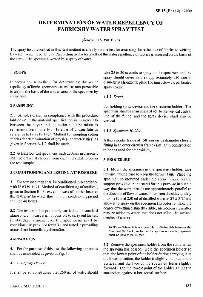
SP 15 (Part 2) :2000
DETERMINATION OF WATER REPELLENCY OF
FABRICS BY WATER SPRAY TEST
(Source : IS 390:1975)
The spray test prescribed in this test method is a fairly simple test for assessing the resistance of fabrics to wkktingby water (water repellency). According to this test method the water repellency of fabrics is assessed on the basis ofthe area of the specimen wetted by a spray of water.
1 SCOPE
It prescribes a method for determining the waterrepellency of fabrics (permeable as well as non-permeableto air) on the basis of the wetted area of the specimen byspray test.
2 SAMPLING
2.1 Samples drawn in compliance with the procedurelaid down in the material specification or as agreed tobetween the buyer and the seller shall be taken asrepresentative of the lot. In case of cotton fabricsreference to IS 3919:1966 ‘Method for sampling cottonfabrics for determination of physical characteristics’ asgiven in Section A-1/2 shall be made.
2.2 At least four test specimens, each 230 mm in diameter,shall be drawn at random from each individual piece inthe test sample.
3 CONDITIONING AND TESTING ATMOSPHERE
3.1 The test specimen shall be conditioned in accordancewith 1S 6359:1971 ‘Method of conditioning of textiles’,given in Section B- 1/1 except in case of fabrics heavierthan 270 g/m2 for which the minimum conditioning period
shall be 48 hours.
3.2 The tests shall be preferably carried out in standardatmosphere. ln case it is not possible to carry out the testin standard atmosphere, the specimens shall beconditioned as provided for in 3.1 and tested in prevailingatmosphere immediately thereafter.
4 APPARATUS
4.1 For the purpose of this test, the following apparatus
shall be assembled as given in Fig. 1.
4.1.1 A Spray Device
Itshall be so constructed that 250 ml of water should
take 25 to 30 seconds to spray on the specimen and the
spray should cover an area approximately 150 mm in
diameter in a horizontal plane 150 mm below the perforatedspray nozzle.
4.1.2 Stand
For holding spray device and the specimen holder. The
specimen shall beat an angle of 45° to the vertical centralline of the funnel and the spray device shall also be
vertical.
4.1.3 Specimen Holder
A thin circular frame of 150 mm inside diameter closely
fitting in an outer circular frame (similar in constructionto hoops used for embroidery).
5 PROCEDURE
5.1 Mount the specimen in the specimen holder, face
upward, taking care to keep the former taut. Place the
specimen so mounted under the spray nozzle on thesupport provided in the stand for this purpose in such a
way that the warp threads are approximately parallel to
the direction of flow of water. Pour from the sides quicklyinto the funnel 250 ml of distilled water at 27 + 2°C and
allow it to spray on the specimen (In order to make the
degree of wetting distinctly visible, such colouring mattermay be added to water, that does not affect the surface
tension of water).
NOTE— Where it is not possible to distinguish between the‘face’and the ‘back’,surface of the specimen mounted upwardsshall be held to be its face.
5.2 Remove the specimen holder from the stand whenthe spraying has ceased. Hold the specimen holder sothat, the lowest point of the holder during spraying is inthe lowest position, the holder is slightly inclined to thevertical, and the face of the specimen leans slightlyforward. Tap the lowest point of the holder 3 times insuccession against a horizontal surface.
1..-. ,.
\
PART 2, SECTION C/l 1 187
I I
~)’i
I
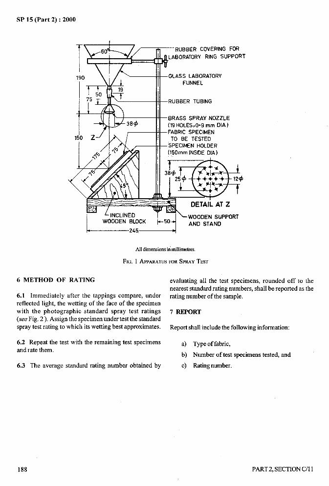
A-
SP 15 (Part 2) :2000
— RUBBER COVERING FOR
t
LABORATORYRING SUPPORT
–GLASS LABORATORYFUNNEL
–RUBBER TUBING
-BRASS SPRAY NOZZLE(19 HOLES,009 mm DIA)
-FABRIC SPECIMEN
TO BE TESTED–SPECIMEN HOLDER
(l!jOmmlNSIDEDIA )
~ -&38+
25c$ ~++++
E:<
124& Fj*+
+*
a
DETAILATZ
4\wooDEfIj suppoRT
50AND STAND
k---———KI~
Alldimensionsinmillimetres.
FIG. 1 APPARATUSFORSPRAYTEST
6 METHOD OF RATING evaluating all the test specimens, rounded off to thenearest standard rating numbers, shall be reported as the
6.1 Immediately after the tappings compare, under ratingnumberof the sample.
reflected light, the wetting of the face of the specimenwith the photographic standard spray test ratings 7 REPORT(see Fig. 2). Assign the specimen under test the standardspray test rating to which its wetting best approximates. Report shall include the following information:
6.2 Repeat the test with the remaining test specimens a) Type of fabric,and rate them.
b) Number of test specimens tested, and
6.3 The average standard rating number obtained by c) Rating number.
.z. -
>
I
188 PART2, SECTION C/l 1
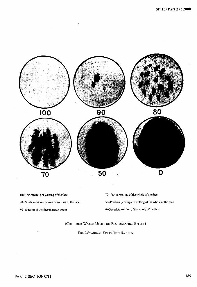
..
!00
70
100-No sticking or wetting of the face
90
50 L
SP 15 (Part 2) :2000
80
70- Partialwettingof thewholeof the face
o
9& Slight random sticking or wetting of the face S&Practically complete wetting of the whole of the face
80-Wetting of the face at spray points &Complete wetting of the whole of the face
(COLOUREDWATERUSEDFORPHOTOGRAPHIC
FIG.2 STANDARDSPMY TESTRATINGS
PART2, SECTION C/l 1
EFFECT)
189
.—
~... --,
),
/
SP 15 (Part 2) :2000
DETERMINATION OF WATER ABSORPTION AND PENETRATION
OF FABRICS USING BUNDESMANN TYPE APPARATUS
(Source : IS 392: 1989)
The work carried out with the Bundesmann apparatus has produced evidence of unidentified variables. Thereproducibility of the method is such that although variability within tests or a given apparatus may be reduced to asatisfactory level, the variability between tests on different apparatus may be large. However, for testing water-
repellency and water resistance of textile fabrics, the use of the Bundesmann apparatus is well established since themethod fulfils the need where quality control testing within a laborato~ is concerned.
The Bundesmann test is used to assess the behaviour of water resistant fabrics when exposed to heavy rain. To
assess the efficiency of proofing of water resistant fabrics permeable to air, the quantity of water absorbed by thespecimen and as a result of exposure to artitical rainfall for the period of test are measured separately, and the dataconsidered collectively.
1 SCOPE
1.1 It prescribes a method for determination of waterrepellency, resistance to wetting (in term of waterabsorbed ) and resistance to penetration by water in termsof water penetrated) of fabrics by the Bundesmann typeapparatus.
1.1.1 It is primarily applicable to woven or non-wovenwater repellent fabrics that are permeable to air.
2 PRINCTPLE
Four specimens of the fabrics under test aresimultaneously exposed to a simulated heavy rain showerof controlled intensity, while the specimen as a whole isflexed and the under surface subjected to the rubbingaction. The water absorbed by the specimens isdetermined after the test is over which is the measure forresistance to wetting. The penetrated water collected incups is the measure for resistance to penetration by water.
3 SAMPLING
Sample shall be drawn so as to be representative of thelot. Sample drawn in compliance with the procedure laiddown in the material specification or as agreed to betweenthe buyer and the seller shall be taken as representativeof the lot. In case of cotton fabrics, reference to SectionA-1/2 shall be made.
4 PREPARATION OF TEST SPECIMENS
4.1 Condition the test sample as specified in 5.1. From
each individual piece in the test sample, cut out fourcircular test specimens without any crease, each of
190
140 mm diameter with a circular dye such that each is
taken from different location spaced at least 100 mm away
from the edge of the fabric sample being tested. The
specimens shall not be folded, ironed or treated otherwise
during the interval between the drawing of the sample
and testing, except for conditioning. If possible thespecimens should not be taken directly from the ends of
the material, since experience has shown that the areadensity (for example, structure) and the finishing may be
different to that of the majority of the fabric.
NOTE— The cutting of specimens by means of a circularcutting die and press is facilitated if squares 150 mm x 150 mmare first cut from the fabric sample.
5 CONDITIONING AND TESTING ATMOSPHERE
5.1 The test specimens shall be conditioned in the
standard atmsophere at 65 * 2 percent relative humidity
and 27 + 2°C temperature at least for 24 hours
(see IS 6359:1971 ‘Method for conditioning of textiles’
given in Section B-1/1). In case of fabric specimens
heavier than 270 g/m2, the minimum conditioning
period shall be 48 hours.
5.2 The tests shall be preferably carried out in standardatmosphere (see 5.1). In case it is not possible to carry
out the test in standard atmosphere, the specimens shall
be conditioned as provided for in 5.1 and tested in
prevailing atmosphere within 15 minutes of their removalfrom the standard atmosphere (see 5.1).
6 APPARATUS
6.1 The apparatus shall be of the continuous-shower
type (see Annex A for details).
PART2, SECTION C/12
).,,.“
( II I
l!
,.4,
.—
SP 15 (Part 2) :2000
k
6.2 Suitable Means for Cutting Specimens of into position to intercept the shower, stop the motor and . ..
140 mm Diameter remove the cup assembly to its stand. Dry the outside of ,~the draincocks. Drain each cup through the draincock
A circular die shall be used with a press or a template and into a 100 ml graduated cylinder and check that thescissors. j
,. ..... ‘
required rate of flow has been obtained. -
6.3 A Mechanical Shaker, conforming to requirements 7.2 Before mounting the test specimens, dry all parts ofgiven in A-5. the cups, wipers and clamps that may come in contact
with the specimens. Remove any water in the exit tubes.6.4 A Stop-Watch or Stop Clock Do not dry the insides of the cups which should be-in
drained condition at the start of each test. Close the6.5 Airtight Containers draincocks.
These containers shall be of known mass and of such ashape and size that the specimen may be inserted withoutbeing creased before exposure to the shower.
6.6 A Balance, sensitive to 0.01 g.
7 PROCEDURE
7.1 Determine the mass of each conditioned specimen ina tared airtight container to the nearest 0.01 g. Set theshower working. The water supply used for the testshall conform to the following requirements and anyblocking to the drop-forming system (by foreign matter,etc) must be avoided. Use of a filter (containing porcelain,Kieselghur candles) on water feeding is recommended.
a) TemperatureThe temperature of water in the shower tank
shall be 27 + 2“C. A thermostatically controlleddomestic electric water-heater may be used tomaintain the required temperature.
b) pHThepH of the water shall be 7.0 + 1.0.
NOTE — If required, pH may be adjusted by passage of waterthrough saitable ion-exchange resins, or distilled water maybe used,
c) Rate of FlowThe rate of flow of water into a cup shall be
65+ 3 ml/min per cup.
7.1.1 Check the rate of flow at least once every 60 min ofcontinuous operation as follows:
Place the cup assembly in position inside the apparatus,with the cups drained and the draincocks closed. Switchon the motor. Swing away the tray to allow the drops tofall on the cups, simultaneously starting the stop watchor stop clock. Expose the cups for 1 rein, swing the tray
7.3 Mount the specimens with the wiper mechanism inthe depressed position. Lay the specimens over the cups
and apply the size of clamping ring that will expose an
area of specimen with diameter as close as possible to100 mm. The specimens must be in continuous contact
with the rims of cups without folds or other irregularity.Lock the clamping rings in position with the spring-
operated clamps.
NOTE— It is important to note that the clamps should beso designed that according to its thickness, the test specimenis not exposed where it is mounted over a hard backing(for example, the outside of the cup rim) since the impact ofthe shower on fabric so mounted may lead to an increase inpenetration through the test specimen.
7.4 Release the wiper arms, if necessary and place thecup assembly in position inside the apparatus. Switch
on the motor. Swing away the tray to allow drops to fall
on the specimens, simultaneously starting the stop-watchor stop-clock. Expose the specimens to the shower for ~10 min unless otherwise agreed between the buyer and
the seller.
7.5 At the end of the test period, swing the tray into
position to intercept the shower, stop the motor andremove the cup assembly to its stand. Immediately
‘unclamp each specimen ftom the cups and remove the
loosely attached water by gripping each specimenwithout folding or creasing it in the clip of the mechanical
shaker and rotating the handle so that the specimenreceives 10 shakes. Transfer each specimen to an airtightcontainer immediately after the shaking is completed.
7.6 Determine the mass of each loaded container to thenearest 0.01 g.
7.7 Dry the outside of the closed drairtcocks. Individually
drain each cup into a measuring cylinder and measure tothe nearest millilitre the volume of water collected fromeach cup separately.
PART 2, SECTION C/12 191
/
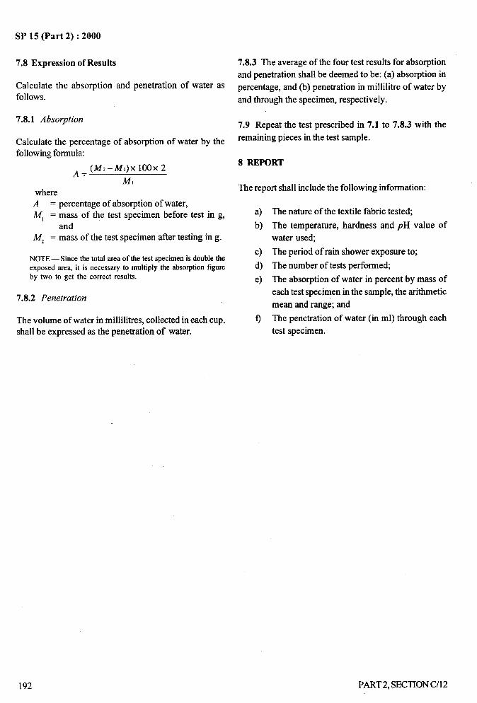
AL_!----
SP 15 (Part 2) :2000
7.8 Expression of Results 7.8.3 The average of the four test results for absorption
and penetration shall be deemed to be: (a) absorption inCalculate the absorption and penetration of water as percentage, and (b) penetration in millilitre of water byfollows. and through the specimen, respectively.
7.8.1 Absorption7.9 Repeat the test prescribed in 7.1 to 7.8.3 with the
Calculate the percentage of absorption of water by the remaining pieces in the test sample.
following formula
*= (M2-M1)X1OOX 28 REPORT
M,The report shall include the following information:where
A = percentage of absorption of water,Ml = mass of the test specimen before test in g, a) The nature of the textile fabric tested;
and b) The temperature, hardness and pH value of
Mz = mass of the test specimen after testing in g. water used;
NOTE— Since the total area of the test specimen is double thec) The period of rain shower exposure to;
exposed area, it is necessary to multiply the absorption figure d) The number of tests performed;by two to get the correct results. e) The absorption of water in percent by mass of
7.8.2 Penetrationeach test specimen in the sample, the arithmetic
mean and range; and
The volume of water in millilitres, collected in each cup, f) The penetration of water (in ml) through each
shall be expressed as the penetration of water. test specimen.
/
,:
192 PART2, SECTION C/12
I
II
SP 15 (Part 2) :2000
ANNEX A
(Clause 6.1)
BUNDESMANN TYPE APPARATUS
A-1 GENERAL DESCRIPTION
A-1.l The Bundesmann apparatus (see Fig. 1) shall beprovided with a water tank fitted with a number of finejets to generate a shower of water simulating rainfall.The tank shall be mounted on a fixed height above thefour metal test cups provided for mounting the specimens.The cups shall be mounted on the apparatus in such amanner that they can be rotated by means of an electricmotor ensuring equal exposure for each specimen tofalling water. The interior of each cup (or specimen holder)shall be fitted with an automatically worked wiper device.The wiper arms shall press lightly against the specimenby means of springs so that the specimen is flexedslightly in addition to the rubbing action as the wiperarms pass over its surface. The cups and base plateshall be separated fi-om the electric motor by means of a
sheet metal trough.
A-2 SHOWER
A-2.1 The shower tanks shall be provided with 304 brass
jets made as shown in Fig. 2. They shall be placed 20mm apart centre-to-centre.
A-2.2 The means shall be provided for the formation of
uniformly spaced drops of average mass 0.075+0.010 gwhen the rate of flow of water at 27 + 2°C andpH 6 to 8 isestablished at 65 + 3ml/min per cup.
A-2.3 The drops shall fall vertically and cover an areagreater than that swept by the cups as the cups assemblyrotates. The vertical distance between the centre of thespecimens when fixed in a position at which the dropsare released, shall be 1 500+ 10 mm.
A-3 CUP ASSEMBLY
A-3.1 The cup assembly shall rotate at 5 + 1 rev/reinunder the shower.
A-3.2 Four cups shall be so mounted on the assemblythat the specimens are tilted 10 to 15° to the horizontalso as to shed water outwards. The centre of the mountedspecimens shall be 105+ 10 mm from the vertical axis
of rotation of the cup assembly.
PART2, SECTION C/12
A-3.3 The cups having a circular orifice shall beprovided with clamps of such a kind that an area of thespecimen with 100 mm diameter is exposed. Thereshall be no leakage round the mounted specimen intothe cup and through the specimen at the clamps.
A-3.4 An exit hole or aperture of 7 + Imm diameter shallbe provided for allowing air displacement but notpermiting the ingress of water into the cup. The cupsshall have a minimum capacity of 350 ml when water fillsthe cup up to the exit hole. The cup shall be providedwith draincocks; having a bore of 3 mm, A4in so that thewater collected may be completely drained.
NOTE— The air exit holes in the cups may be advantageouslyprovided with external metal tubes that are bent in such a waythat the impact of the shower on the cup assembly does notcause the water to splash up into the tubes during the test period.This will prevent water that overtlows down the cup during theexposure from becoming lodged in the exit hole.
A-3.5 Each cup shall be provided with four wiper arms
fixed at right angles to each other and rotating about the
axis of the cup. When released the highest point of the
wiper arm shall stand 3.0 mm proud of the rim of the cupand the wipers shall press initially against the specimen
with a load of 400 +50 g. The wiper arms shall sweep an
arc of 100 + 5°, making 20 complete oscillations perminute. The length of the base of the wiper arms shall
be 96 mm. the maximum width of the wiper and its support
shall not exced 9.5 mm. The horizontal locating surfacesof the wiper supports shall lie in the same plane and thisplane shall beat right angles to the axis of rotation of the
wiper-head spindle.
A-3.6 The wiping surfaces shall be made fromstainless steel of good quality. The operative surfaceof the wipers shall be formed by machining thematerial to forma part of the cylinder having a diameter
12.7 + 0.1 mm with its axis disposed radially aboutthe wiper head spindle when viewed from above and
tilted downwards 2°+ 3’ when viewed horizontally. Thethickness of the wiping surface shall be from 5.08 to
5.13 mm. The extremities of the wipers shall have aradius of 3 mm. The centre of the wipers shall beindented in the form of a cone with a diameter of 13
mm diminishing to 11 mm over a depth of 0.8 mm so
193
),>;,
I,: _
SP 15 (Part 2) :2000
that the center of indentation is coaxial with the wiperhead spindle and at the intersection of the axis of thewiper cylinders. Care shall be taken to ensure that theends of the single wiper make a closely fitting butjoint with the opposite sides of the doubled wiper. Themachining marks shall then be carefully removed byfilling parallel to the cylinder axis and final polishgiven to the surface by Grade 00 emery paper to whichis added a little paraffin. Paraffin residues which
would contaminate the next specimen to be tested,should be removed by subsequent cleaning, such as,with trichloroethylene.
ofjets. A piece of closely woven cotton fabric, wrappedaround a perforated metal support, may be efficientfilter for use on Bundesmann type apparatus.
A-5 MECHAMCALSHAKER
A-5.1 A clip for holding the specimen shall be attachedat the end of 213 mm long arm to which a torque of9.7 kgf cm should be applied when this arm is released.The arm shall move through an arc of 170° to thehorizontal position and come to rest with a residualtorque of 1.15 kgf cm.
-!.-.
./
AA FJLTER A-5.2 The mass of the arm shall be such that the velocitymeasured tangentially at a radius of 195 mm and at a
A-4.1 It is desirable for almost all water supplies, to deflection of 140* 5° from the initial position shall beprovide a filter to obviate the need for frequent cleaning 5.4 * 0.54 mls.
194 PART2, SECTION C/12
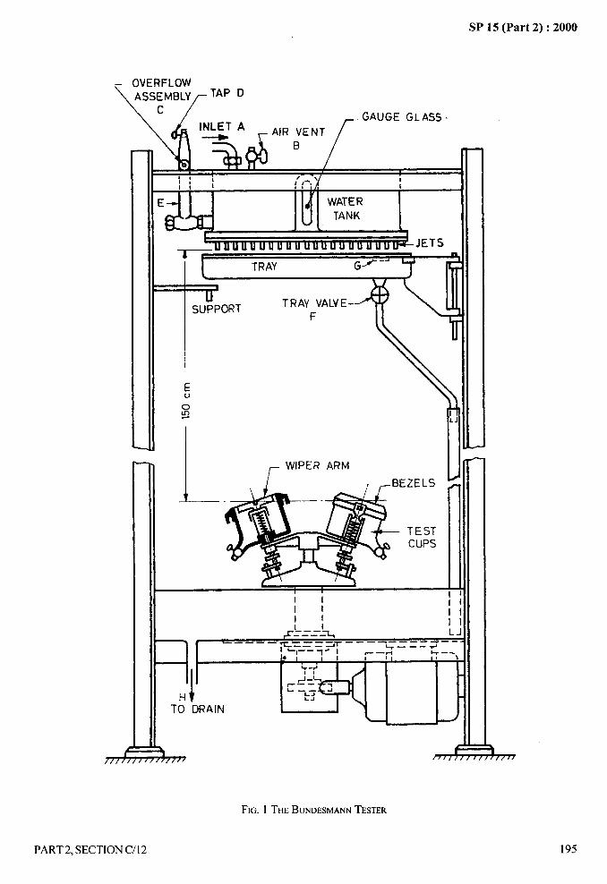
,A
SP 15 (Part 2) :2000. .-
— OVERFLOW
\ASSEMBLYf TAP D\L/ ,. .,----
‘-5-
)f(yAFA’R~ENTf“’”’’’LA’—
% oh Ii ~-1/, ‘f t I
EL
TRAY VALVE- \ 11SUPPOR-F
~ WIPER ARM I llT-1 ---- .- Ull
TESTCUPS
I IIi
ii
IIIi
i I II—--A-.--. * ‘J.—— - — —-— -——. —-——-L.___— -y
I -14%——–+
%—-
y#
#-
LAHtTO DRAIN
b
),,, ///[//[///7
FIG. 1 THEBUNDESMANNTESTER
PART2, SECTION C/12 195
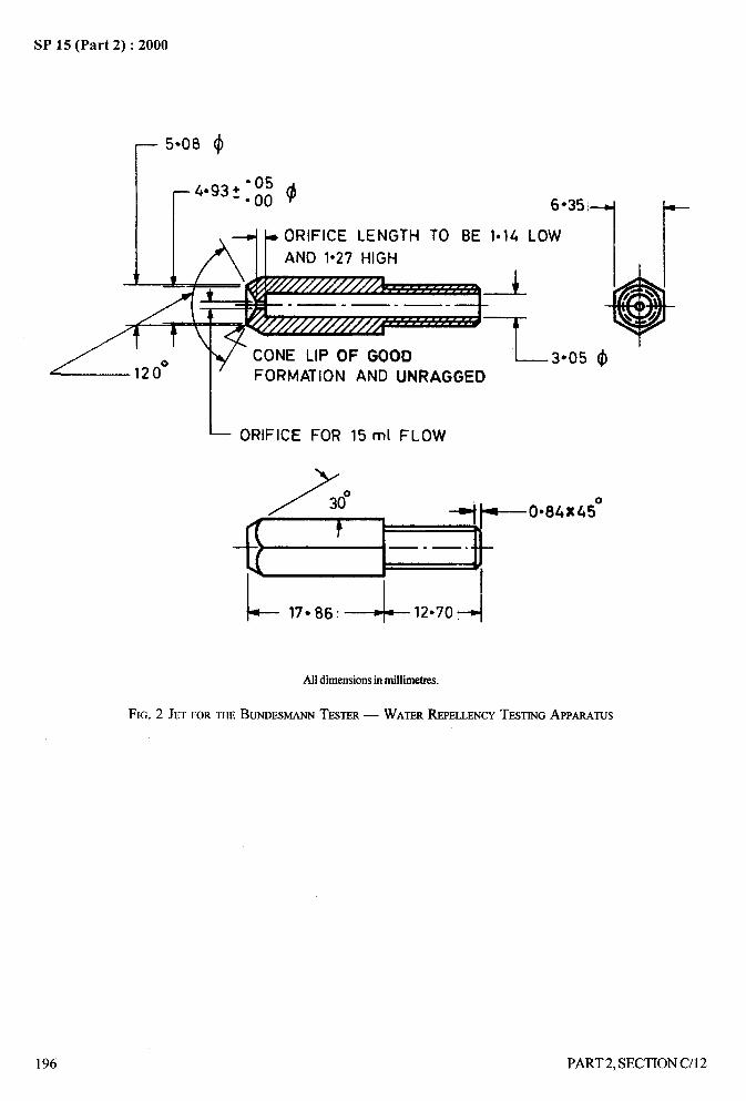
.—-SP 15 (Part 2) :2000
r 5*O8 $
_4.93+ “05-.00 ~ 6*35
* ORIFICE LENGTH TO BE 1*14 LOW
AND 1“27 HIGHv w
*Ir
A
7/ +
/\.— .— -—.
L)
CONE LIP OF GOOD 3“05 (#)FORMATION AND UNRAGGED
L ORIFICE FOR 15 ml FLOW
Y
~“”a’x”o+- 17Q86:+ 12*701+
Alldimensionsin millimetres.
FIG. 2 JETFORm BUNDESMANNTESTER— WATERREPELLENCYTESTINGAPPMmS
196 PART2, SECTION C/12
II1’
SP 15 (Part 2): 2000
DETERMINATION OF RESISTANCE TO PENETRATION BY WATER
OF FABRICS BY HYDROSTATIC HEAD TEST
(Source : IS 391:1975)
The hydrostatic head test prescribed in this method is a relatively simple test indicating the effect of fabric structureon its resistance to penetration by water. The resistance offered by the fabrics to penetration of water is expressedin centimetres of static head of water.
1 SCOPE
It prescribes a method of determining the resistance offabrics (permeable as well as non-permeable to air) towater penetration by hydrostatic head test.
2 SAMPLING
2.1 Samples drawn in compliance with the procedurelaid down in the material specification or as agreed tobetween the buyer and the seller shall be taken asrepresentative of the lot. In case of cotton fabricsreference to IS 3919:1966 ‘Methods for samplingcotton fabrics for determination of physicalcharacteristics’ given in Section A-1/3 shall be made.
2.2 At least eight test specimens, each 100 mm x 100 mm,shall be drawn at random from each individual piece inthe test sample.
3 CONIMI’IONING AND TESTING ATMOSPHERE
3.1 The test specimens shall be conditioned inaccordance with IS 6359:1971 ‘Atmospheric conditionsfor testing’ given in Section B-1/1 except in case offabrics heavier than 270 g/m2 for which the minimumconditioning period shall be 48 hours.
3.2 The tests shall be preferably carried out in standardatmosphere. in case it is not possible to carry out thetest in standard atmosphere, the specimens shall beconditioned as provided for in 3.1 and tested in prevailingatmosphere immediately thereafter.
4 APPARATUS
4.1 The apparatus shall meet the following requirements:
a) Means shall be provided for clamping thespecimen of fabric in such a manner that:1) the specimen is horizontal,2) a circular area of the fabric (50 mm
dia) shall be subjected to a steadilyincreasing water pressure on one face,
3) no leakage of water at the clamps shalloccur during the test period,
4) the specimen shall not slip in the clamps,and
5) any tendency for penetration to occur atthe clamped edge of the specimen isarrested.
b) The distilled water in contact with the testspecimen shall be maintained at 27 * 2°C.
c) The rate of increase of water head shall be100 +5 rnrn/min.
d) The manometer connected to the testing head(s)shall allow pressure to be read to an accuracyof 5 mm head of water.
NOTE— A suitable apparatus is described in Annex A
5 PROCEDURE
5.1 Prepare the apparatus for the test as advised by themanufacturer. Wipe all water from the clamping surface.Take the specimen and clamp it on the testing head insuch a manner that there is an air space between the faceof the fabric and the surface of water. Immediately subjectthe specimen to increasing water pressure [see 4.1 (c)].Watch continuously for evidence of penetration by thewater through the specimen.
5.2 Carefully observe for drops of water forced throughthe cloth. Ignore drops coming through the test specimenat the first two places. Record the head of water in
centimetres immediately when a drop of water comesthrough a third place in the specimen.
5.3 Repeat the test with the remaining test specimens.
6 REPORT
The report shall include the following information:
a) Type of fabric;b) Number of test specimens tested; andc) Mean resistance of fabrics, in centimetres of
water head.
PART2, SECTION C/13 197

- .-SP 15 (Part 2) :2000
A-1 DESCRIPTION
A-1. 1 The apparatus(see Fig. 1 and 2 ):
a)
b)
c)
d)
e)
ANNEX A
(Note in Clause 4.1)
HYDROSTATIC HEAD TEST APPARATUS
shall consist of the following
Brass Cylinder (M) – Closed at the bottomand open at the top; provided with a tube R atthe side, the latter serving as inlet and outletfor water. The smooth flanged top of thecylinder in order to prevent darnage to the testspecimen, shall be provided with a ring of thinrubber of 50 mm internal diameter (for detailsand dimensions of the cylinder, see Fig. 2).Ring Clamping Device – A device to clamp ametal ring to top of cylinder Mby screw J. The
metal ring of 50 mm internal diameter, in order toprevent damage to the test specimen, isprovided with a ring of thin rubber of 50 mminternal diameter.
Graduated Glass Tube – With the zero markexactly in level with the top of the cylinder M.Water Res&voir (see Fig. 1) – To constantlysupply water to the constant water headvessel C.Constant Water Head – The diameter of theend of its outlet tube G is so adjusted that whenit is delivering water into graduated tube H, thelevel of water in it rises at a constant rate of 100mrm’min.
A-2 OPERATION
A-2.1 Close taps K, L and F and open taps S and B.
Allow the distilled water from the reservoir A(maintained at 27 * 2°C) to run into the vessel C till itattains a constant level (The water will maintain constantlevel when it has reached the top of the overflow tube D,
all excess water being drained off through the tube D.).Close tap S, open taps L and K and fill the brass cylinderA4with water till it is nearly full. Close the tap Kand openthe tap S. Lay the test specimen on the rubber ring of thecylinder M, Place the clamping ring on top of the testspecimen and fix the former rigidly by operating the screwJ. Open the tap F to allow inflow of water into the tube H(Just as the level of water in tube H begins to go abovezero mark the test specimen which is at the same levelshould begin to bulge.). Continue the flow of water
rRESERYUIR
A
alTAPa
CONSTANT -WATER-~%
HEAD VESSEL C .x= Z-,= =-- ;=
.= ___ s--
CYLINUM M
FIG. 1 HYDROSTATICHEADTESTAPPARATUS
CLAMPINGs
‘F.
k
L’CYLINDER M
Alldimensionsin millimetres.
FIG. 2 TEST-HEADOFHYDROSTATICHEADTESTAPPARAmS
steadily into the graduated tube Hat such a rate that thelevel of water in the tube rises by 100 mm/min.
..
198 “
/
PART 2, SECTION C/13
SP 15 (Part 2) :2000
RESISTANCE TO PENETRATION BY WATER OF FABRICS BY STATIC___.-
PRESSURE HEAD TEST
‘1“.:,---
(Source : IS 7940:1976) ii
The static pressure head test prescribed in this method is a relatively simple test and gives a good indication of theeffect of fabric structure on resistance to penetration by water of fabrics. The resistance by a fabric to penetration ofwater is measured in terms of the amount of water penetrating through the fabric per unit area per unit time under astatic head of water.
1 SCOPE
It prescribes a method for determining resistance topenetration by water of fabrics by static pressure headtest. It is applicable to fabrics non-permeable to air.
2 PRINCIPLE
A circular specimen of the fabric is mounted horizontallyand water is forced through the specimen fi-om upperside under static pressure. The volume of water collectedin a given time is expressed in terms of the volume ofwater penetrated per unit area of the fabric per unit time(1/m2ih).
3 SAMPLING
Samples shall be so drawn as to be representative ofthe lot. Samples drawn in compliance with the procedurelaid down in the material specification or as agreed tobetween the buyer and the seller shall be taken asrepresentative of the lot. In case of cotton fabricsreference to IS 5463:1969 ‘Methods for sampling ofcotton fabrics for chemical tests’ given in SectionA-1/3 shall be made.
4 ATMOSPHERIC CONDITIONS FORCONDITIONING AND TESTING
4.1 The test smaples shall be conditioned in accordancewith IS 6359:1971 ‘Method of conditioning oftextiles’ given in Section B-l/l except in case offabrics heavier than 270 g/m2 for which the minimumconditioning period shall be 48 hours.
4.2 The tests shall be carried out in standard atmosphere.
5 PREPARATION OF TEST SPECIMENS
From each test sample prepare circular test specimensof 13 cm diameter from different portions at random.Prepare at least 3 test specimens.
PART 2, SECTION C/14
6 EQUIPMENT
6.1 Means for:
a)
b)
c)
clamping the specimens with a circular test
portion of 10 cm diameter,
applying the required static water head pressure
and maintaining the pressure throughout the
test, and
collecting penetrated water without any loss.
6.1.1 A typical equipment is detailed in Annex A.
6.2 Water
Having pH between 6 and 8.5 and total hardness not
exceeding 50 ppm, maintained at the temperature of
testing atmosphere (see 4.2).
‘.7 PROCEDURE .%,./
7.1 Adjust the water pressure head level to the required
height. Place the container for collecting penetrated water
in position. Open the water supply to the apparatus and
note the time. Maintain the water level height for 1 hour.
7.2 After 1 hour, immediately remove the water container
used for collecting penetrated water and determine the
voIume of water collected in litres.
7.3 Similarly carry out the test for other test specimens.
8 CALCULATION
8.1 From the volume of water collected as in 7.1 and 7.2
calculate the rate of water penetration (water resistance)
in terms of litres per square metre per hour as follows:
199
I
1’
‘L_.i
SP 15 (Part 2) :2000:.. ....1
Volume of water collected inlitres x 100 x 100
Rate of waterpenetration, I/m’/h =
3.14X5X5
Volume of water collected inlitres x 400
— 3.14—
8.2 Determine the average of all the observations.
9 REPORT
The report shall include the following information:
a) Type of the fabric;
b) Number of specimens tested;
c) Static water pressure head in millimetres; and
d) Rate of water penetration in litres per square
metre per hour.
.
ANNEX A
(Clause 6.1. 1)
STATIC PRESSURE HEAD TEST APPARATUS
A-1 DESCRIPTION OF THE EQUIPMENT
A-1.l The apparatus (see Fig. 1) consists of a metallicbase ring with an internal diameter of 10 cm (forholding the specimen), and a metallic dome ofdiameter 10 cm at the base provided with a water inletand an air valve. The dome is fitted in a metal frame,so that the dome can be moved up and down or firmlyfixed over the base ring. A funnel is fitted under thebase ring. To collect water leaking through thespecimen, a receptacle is provided. A gauge isattached to the water column for measuring the heightof the column. The water column in connected tothe water inlet on the metallic dome by means of arubber tubing. The apparatus is also provided with anoverflow arrangement (to regulate overflow) and anoverflow outlet.
A-2 OPERATION
A-2.1 Clamp the specimen under test tightly betweenthe base ring and the dome with the help of rubberwashers. Open the water supply and fill the dome withwater, taking care that all entrapped air is removed bypermitting a little quantity of water to come out of theair valve. When the dome is full of water, close thevalve and let the water rise in the water column to therequired height (depending upon the type of fabric).Immediately, place the receptacle under funnel.Maintain, for 1 hour, the water column at the requiredheight by adjusting the overflow arrangement.Immediately after 1 hour, remove the receptacle fromunder the fimnel, and drain off ttie water in the dome bydisconnecting the rubber tubing. Determine the volumeof water which has collected in the receptacle in Iitres.
../
200 PART2, SECTION C/14
II
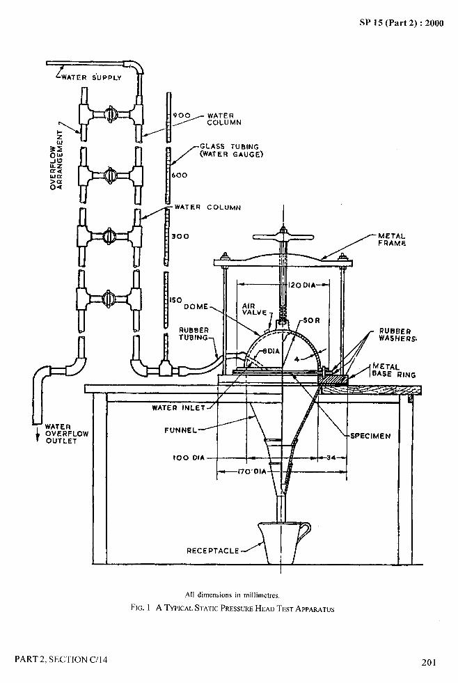
A-
SP 15 (Part 2) :2000
.—.
f-i h
J~:&LfJk
Il./
GLASS TUBING(WATER GAUGE)
I600
1
WATER
300
n
COLUMN
I
%=$==$-”
u [tWATER
OVERFLOWOUTLET
I
All dimensions in millimetres.
FIG. 1 A TYPICALSTATICPRESSUREHEAD TEST APPARATUS
PART 2, SECTION C/14
/
201
I
,:]’I1

- .—-
5P 15 (Part 2) :2000
DETERMINATION OF RESIDUAL SHRINKAGEPOLYESTER SEWING THREADS
(Source: IS 9543:1980)
OF SPUN
1 SCOPE
It prescribes a method for determination of residualshrinkage of spun polyester sewing threads.
2 PRINCIPLE
A sample of textile material under testis exposed to hightemperature (in case of dry shrinkage) and alternativelyimmersed in water and dried (in case of wet shrinkage)and residual shrinkage expressed as percentage decreasein length based on original length of the specimen.
3 APPARATUS
3.1 Mounting Device
The device shall be such that a test specimen of at least100 cm length can be mounted on it, with one of its endsin a fixed clamp under the desired dead weight tensionand
a) exposed to a temperature of 150”C or 180°C asthe case may be (in case of dry shrinkage test);and
b) immersed in water at 100”C (in case of wetshrinkage test).
3.1.1 The mounting device shall be provided withmeans for measuring the initial and final length of testspecimens to a range of 1 mm.
a) after exposure to a high temperature (in case ofdry shrinkage test); and
b) after immersion in water and drying (in case ofwet shrinkage test).
4 PROCEDURE
4.1 Take one of the test specimen and mount it on the
mounting device under tension of 0.45* 0.09 g per tex.Note the original length of the test specimen.
4.2 In Case of Dry Shrinkage Test
Prepare a small skein of the test specimen and suspend itin an oven at a temperature of 150+ 2°C or 180* 2°C for15 minutes. Note the final length.
4.3 In Case of Wet Shrinkage Test
Prepare a small skein of the test specimen and immerseit in a test tube containing water. Add a small quantityof soap solution (O. 1 percent) to ensure adequatewetting out. In order to prevent local heating, immersethe test tube in a water bath at 100”C and keep it in thisposition for 15 minutes. Ensure that the water in thewater-bath is above the level of water in the test tubethroughout the test. Rinse the test specimen in runningtap water and allow it to drip dry without tension. Notethe final length.
5 CALCULATIONS
Calculate the shrinkage as follows:
Shrinkage percent =a–b—Xloo
a
where
a = original length of the specimen, and
b = final length of the specimen (see 4.2 and 4.3).
6 REPORT
Report shall include the following
a) Method employed that is wet or dry;
b) Shrinkage obtained (see 5); and
c) Any deviation from the test method.
202 PART 2, SECTION C/l 5
.4. . . . “.2
SP 15 (Part 2) :2000.-
‘-”
SECTION D
CHEMICAL TESTS
I,, I
I

As in the Original Standard, this Page is Intentionally Left Blank
SP 15 (Part 2) :2000.—-
DETERMINATION OF WOOL CONTENT INWOOLLEN TEXTILE MATERIALS
(Source : IS 8476:1977)
The method determines the total protein content in the woollen textiles materials. However, it does not necessarilymean that the protein content so determined is ‘all wool’. It may also contain other protein fibres besides ‘wool’.
1 SCOPE
It prescribes a method for determination of percentage
of wool in all-wool textiles in any form, such as fibre,
yam, fabrics, druggets and carpets.
2 PRINCIPLE
A pretreated specimen of known oven-dry mass is
dissolved in sodium or potassium hydroxide. The non-
WOOIcontent, including burrs, seeds, etc, is over-dried
and weighed, and percentage of wool content is calculated
therefrom.
3 SAMPLING
Samples shall be so drawn so as to be representative of
the lot. A sample drawn in accordance with the
procedure laid down in the material specification or as
agreed to between the buyer and the seller, shall
constitute the test sample.
4 ATMOSPHERIC CONDITIONS FOR
CONDITIONING
Condition the test specimen to moisture equilibrium in
the standard atmosphere of 27+ 2°C temperature and
65+ 2 percent relative humidity [see also IS 6359:1971
‘Method for conditioning of textiles’ (see Section B- 1/1)].
5 APPARATUS
5.1 Soxhlet Apparatus
5.2 Sintered Glass Crucible No. 1
5.3 Desiccator
5.4 Weighing Balance
Capable of weighing to an accuracy of 10 mg.
PART 2, SECTION D/l
5.5 Drying Oven
Capable of maintaining a temperature of 105+ 3°C and
preferably fitted with weighing balance.
6 REAGENTS
6.0 Quality of Reagents
Unless specified otherwise pure chemicals shall be
employed in test and distilled water shall be usedwherever the use of water as a reagent is intended.
NOTE— ‘Purechemicals’shallmean chemicalsthat do not containimpuritieswhich affectthe test results.
6.1 Sodium or Potassium Hydroxide Solution
5 percent (rrr/v).
6.2 Benzene - Methyl Alcohol Mixture (3 : 2).
6.3 Acetic Acid Solution
3 percent (v/v).
7 PREPARATION OF TEST SAMPLE
Take the sample weighing about 30 g and cut it intopieces, if necessary. Put it in the Soxhlet apparatus and
extract with benzene-methyl alcohol mixture for two
hours at a minimum rate of six cycles per hour. Allowthe solvent to evaporate and then wash the sample inwater (about 500 ml) at 50°C for 30 minutes.
8 PROCEDURE
8.1 Take a representative specimen weighing about 5 g
from the prepared sample and place it in a suitablecontainer. Place the specimen in the drying ovenmaintained at a temperature of 105 + 3°C and dry it toa constant mass.
205
),
/
I
i:
II
SP 15 (Part 2) :2000
A-
-—
NOTE — The mass shall be taken as constantwhen the differencebetweenthetwosuccessiveweighingsmadeat intervalsof20 minutesis less than 0.05 percent.
8.2 Determine the mass of the specimen without
removing it from the oven. In case the drying oven is not
provided with weighing balance, remove the specimen
from the oven and transfer it to a weighing container of
known mass provided with a tight lid. The transference
of the specimen shall be done in as less atirne as possible.
Cool the specimen and the container in a desiccator to
room temperature before weighing. Weigh the container
and determine the mass of the specimen to an accuracy
of 10 mg.
8.3 Put the specimen in a beaker together witi”500 ml of
5 percent sodium or potassium hydroxide solution and
boil slowly until the wool fibres dissolve. After 10 minutes
of boiling, filter through a sintered glass crucible. Wash
the residue first with warm water, then with acetic acid
solution and finally with hot water. Dry the residue at
105 + 3“C.
8.4 Examine carefi.dly the residue and the pores of the
crucible for incompletely dissolved wool. If it is present,
dissolve it by pouring sodium or potassium hydroxide
solution. Rinse and dry the residue at 105+3 “C to
constant mass (see Note under 8.1) and weigh it to an
accuracy of 10 mg.
8.5 Similarly test at least two more test specimens.
9 CALCULATION
9.1 Calculate the wool content for each test specimen asunder:
a–bWool content, percent =TX100
wherea = oven dry mass of the specimen; andb = oven dry mass of the residue.
NOTE — 13.6is standard moisture regain for wool.
9.2 Calculate the average wool content of all the testspecimens.
10 REPORT
The report shall include the following:
a) Type of material;b) Average wool content, percent; andc) Number of test specimens.
206
/
PART 2, SECTION D/l
4-... —
J
b
SP 15 (Part 2) :2000
DETERMINATION OF BITUMEN CONTENT IN. .
LAMINATED JUTE BAGS~
,. ...!$(ho-cc : IS 8477:1985)
Jute bags laminated with craft paper or polyethylene film using bitumen as the bonding material are extensively usedthese days for packing materials like pesticides, fertilizers, etc. Two methods, one based on conditioning of the testspecimens in a standard atmosphere or in a conditioning chamber and the other based on conditioning of the testspecimens in a desiccator containing saturated solution of sodium nitrite were evolved for determining the amount ofbitumen used for bonding the liner and the jute fabric as its quantity is important for the performance of the laminatedjute bag.
1 SCOPE
It prescribes two methods for determination of bitumen
content in laminated jute bags.
2 PRINCIPLE
A specimen of laminated fabric of known mass is takenand the liner is removed by dipping in a suitable solventand then the fabric portion is extracted in Soxhletapparatus. From the mass of the initial piece, liner andextracted fabric, the bitumen content is calculated.
3 SAMPLING
3.1 Lot
The quantity of laminated jute bags purported to be ofone definite type and quality delivered to a buyer againstone despatch note shall constitute a lot.
3.2 The sample shall be so drawn as to be therepresentative of the lot. The sample drawn in accordancewith the procedure laid down in the material specificationor as agreed to between the buyer and the seller shall betaken as representative of the lot.
4 PREPARATION OF TEST SPECIMEN
From the sample, cut four pieces of 100 mm x 100 mmtaking one piece from the area near the mouth, the otherfrom the area close to the bottom and two pieces ffomthe middle portions of the bag. The pieces shall be takenin such a way that they contain spot application portionin case the bitumen is applied off-set.
5 METHOD 1
5.1 Conditioning of Test Specimens
5.1.1 Before testing, condition the specimens to moistureequilibrium in standard atmosphere at 27+ 2°C
PART 2, SECTION D/2
temperature and 65+2 percent relative humidity[see also IS 6359:1971 ‘Method for conditioning oftextiles’ (see Section B-1/1)].
5.1.1.1 When the test specimens have been left in suchan atmosphere for at least 24 hours in such a way as toexpose, as far as possible, all portions of the specimensto the atmosphere, they shall be deemed to have reachedmoisture equilibrium.
5.1.2 In case arrangements are not there for conditioningthe test specimens in standard atmosphere, these maybeconditioned in a conditioning chamber and massdetermined immediately after the removal of the testspecimens from the conditioning chamber.
5.2 Apparatus and Reagents
5.2.1 Soxhlet Apparatus
5.2.2 Weighing Balance – with an accuracy up to 1 mg.
5.2.3 Solvent – Light petroleum or any other suitablesolvent such as trichloroethylene or perchloroethylene.
5.3 Procedure
5.3.1 Take the conditioned test specimens and determinetheir collective mass to the nearest milligram.
5.3.2 Wash all the specimens with the solvent(see 5.2.3) and carefidly separate the liner pieces. Washthe liner pieces with solvent to remove adhering tracesof oil and bitumen.
5.3.3 Dry the liner pieces in air and determine theircollective mass to the nearest milligram (see Note).
NOTE — If the liner pieces are made of crti paper, these shall beconditionedbefore determiningtheir collective mass.
207
/
,
I~! I
I
.— __
SP 15 (Part 2) :2000
t5.3.4 Take the four fabric pieces obtained after theremoval of liner pieces from the test specimens andplace them in a thimble of the Soxhlet apparatus. Takeabout 400 ml of the solvent in the extraction flask.Extract the pieces for 1X to 2 hours at a rate of about6 cycles per hour. Take out the fabric pieces and letthe solvent evaporate.
5.3.5 Condition the fabric pieces as given in 5.1.1or 5.1.2 as the case may be, and determine theircollective mass to the nearest milligram.
5.3.6 Calculate the quantity of bitumen per square metreas given in 7.1 and 7.1.1.
6 METHOD 2
6.1 Apparatus and Reagents
6.1.1 S’oxhlet Apparatus
6.1.2 Weighing Balance – With an accuracy up to 1 mg.
6.1.3 Desiccator – Suitable size, charged with saturatedsolution of sodium nitrite at 27 + 2°C.
6;1.4 Solverrt – Light petroleum or any other suitablesolvent such as trichloroethylene or perchloroethylene
6.2 Procedure
6.2.1 Condition all the test specimens (see 5.1) in thedesiccator charged with saturated solution of sodiumnitrite at 27 + 2°C for at least 24 hours in such a waythat the fabric side of each specimen is exposed to theair inside the desiccator.
6.2.2 Remove all the specimens from the desiccatorand immediately determine their collective mass to thenearest milligram.
6.2.3 Wash all the specimens with the solvent (see 6.1.4)and carefully separate the liner pieces. Wash the linerpieces with solvent to remove adhering traces of oil andbitumen.
6.2.4 Dry the liner pieces in air and determine theircollective mass to the nearest milligram (see Noteunder 5.3.3).
6.2.5 Take the four fabric pieces obtained after theremoval of the liner pieces from the test specimens andplace them in the thimble of the Soxhlet apparatus. Takeabout 400 ml of the solvent in the extraction flask.Extract the fabric pieces for 1% to 2 hours at a rate ofabout 6 cycles per hour. Take out the fabric pieces andlet the solvent evaporate.
208
6.2.6 Place the fabric pieces in the desiccatorcharged with saturated solution of sodium nitrite at27+ 2°C for at least 24 hours exposing both sides ofeach fabric piece as far as possible to the air insidethe desiccator.
6.2.7 Remove the fabric pieces from the desiccatorand immediately determine their collective mass to thenearest milligram.
6.2.8 Calculate the quantity of bitumen per square metreas given in 7.1 and 7.1.1.
7 CALCULATION
7.1 Calculate the quantity of bitumen per square metreby the following formula:
X=25 [a–(b+c+d)]g/m2
where
X = mass of bitumen per square metre of thelaminated fabrics;
a = combined mass of the conditioned testspecimens;
b = combined mass of the liner pieces;
c = combined conditioned mass of the extractedfabric pieces; and
d = correction factor for oil content of the fabric.
7.1.1 Calculate the value of dby the following formula:
Cxyd=—
100where
c = combined conditioned mass of the extractedfabric pieces; and
y = oil content percentage of the fabric as specifiedin the material specification, on conditionedmass basis (see Note).
NOTE — Generally five percent oil content on conditioned massbasis is used for hessian and double-warp thread fabrics made ofjute. For other fabrics use the value as given in the materialspecificationbasedon conditionedmass. Fivepercentof oil contenton conditionedmasscorrespondsto six percentof oil contenton dryde-oiledmaterialbasis.
8 REPORT
The report shall include the following information:
a) Type of material;
b) Bitumen content per square metre; and
c) Method of bitumen application, namely,continuous or off-set bonding.
PART 2, SECTION D/2
---
%.
,1
... ,,
SP 15 (Part 2) :2000
DETERMINATION OF OIL CONTENT OFJUTE YARN AND FABRICS
(Source: IS 2969:1974)
During conversion of jute fibres into yarn considerable amount of oil, commonly known as batching oil, is used inthe form of its emulsion in water. Some or all of the oil is present in the later stages of manufacture of jute goods.The finished jute goods usually contain 5 to 9 percent oil. In the case of special goods, the oil content maybe upto 1 percent only.
1 SCOPE
It prescribes two methods for determination of oil contentof all types of jute yam and fabrics, namely conditioned-mass method and oven-dry method.
2 PRINCIPLE
A known amount of the sample is extracted withtrichloreoethylene or light petroleum or n-hexane inSoxhlet apparatus. The solvent is removed by distillationand the extract is weighed. The mass of the extract isexpressed as a percentage of the oven-dry mass of the”extracted specimen or conditioned mass of the testspecimen before extraction.
3 SAMPLING
3.1 Lot
The quantity of jute yam or fabric purported to be of
one definite type and quality delivered to one buyeragainst one despatch note shall constitute a lot.
3.2 Samples from the lot shall be so drawn as to berepresentative of the lot. Samples drawn in accordancewith the procedure laid down in the specification forthe material or as agreed to between the buyer and theseller shall be held to be representative of the lot.
4 PREPARATION OF TEST SPECIMENS
From each bundle of yam or cut of fabric selected, drawa test specimen weighing 6 to 8 g.
5 ATMOSPHERIC CONDITIONS FORCONDITIONING AND TESTING
5.1 Conditioned-Mass Method
The test shall be carried out in the standard atmosphereafter conditioning the test specimens as prescribed in
PART 2, SECTION D/3
IS 6359:1971 ‘Method for conditioning of textiles’
(see Section B-l/l).
5.2 Oven-Dry Method
The test may be carried out in the prevailing atmosphere.
6 APPARATUS
6.1 Soxhlet Apparatus
6.2 Drying Oven – capable of maintaining atemperature of 105 * 3°C.
6.3 Weighing Balance – capable of weighing to anaccuracy of 1 mg.
7 REAGENTS
7.1 Quality of Reagents
Unless specified otherwise, pure chemicals shall beemployed in test and distilled water shall be used wherethe use of water as a reagent is intended.
NOTE — ‘PoreChemicals’shallmeanchemicalsthat do not containimpuritieswhich affectthe test results.
7.2 The reagents to be used in the test shall be asfollows.
7.2.1 Trichloroethylene
7.2.2 Light Petroleum
7.2.3 n-hexane
Boiling range 40 to 60”C.
8 PROCEDURE
8.1 Conditioned-Mass Method
8.1.1 Take a test specimen conditioned in the standardatmosphere (see 5.1 ), determine its mass (Mc) correct
209
—__..
_-
\,,“6.,,
/
4,
.. . ...—
SP 15 (Part 2) :2000
to 1 mg and place it in the thimble of the Soxhlet
apparatus. Take about 100 ml of trichloroethylene or
light petroleum n-hexane in the extraction flask
previously cleaned, dried and weighed correct to 1 mg.
Extract the test specimen for 1!4 to 2 hours with a
minimum of 10 siphoning per hour. Disconnect the
apparatus.
8.1.2 Recover the excess of the solvent by heating the
flask in a water-bath, maintained at 90 to 95°C if the
solvent is trichloroethylene, 60 to 65°C if the solvent is
light petroleum and 70 to 75°C of the solvent in
n-hexane, and simultaneously allowing a stream of air
to pass through the flask by means of a tube terminating
just below its neck. Remove all traces of moisture by
heating the flask at 105 + 3°C for % hour. Weigh the
flask and determine the mass of the extract (Mc) correct
to 1 mg.
8.1.3 Repeat the test with the remaining test specimens.
8.2 Oven-Dry Method
8.2.1 Take a test specimen, weigh it to the nearest
milligram and place it in the thimble of the Soxhlet
apparatus. Take about 100 ml of trichloroethylene or
light petroleum in the extraction flask previously
cleaned, dried and weighed correct to 1 mg. Extract the
test specimen for 1!4 to 2 hours with a minimum of 6
siphoning per hour. Disconnect the apparatus.
8.2.2 Withdraw the specimen from the apparatus, open
it out and allow the excess solvent to evaporate. Dry
the specimen for 4 hours at 105 + 3°C in the drying
oven. Transfer the dried specimen to a tared airtight
container, cool and weigh. Determine the oven-dry mass
of the specimen (Md) correct to 1 mg.
8.2.3
8.2.4
Proceed further as in 8.1.2.
Repeat the test with the remaining test specimens.
9 CALCULATIONS
9.1 Calculate the oil content percent of each specimen
to the nearest 0.1 percent as follows:
Conditioned-mass basis:
MeOil content percent = ~ x 100
cwhere
Me = mass in milligrams of the extract (8.1.2), and
&fc =mass in milligrams of the conditioned
specimen (8.1.1).
Oven-dry-mass basis:
Oil content percent
where
Me=—X1OO
Md
Me = mass in milligrams of the extract (8.2.3), and
Md = mass in milligrams of the oven-dry de-oiled
specimen (8.2.2).
9.2 Calculate the average of all the values obtained as
in 9.1 to the nearest 0.1 percent.
10 REPORT
The report shall include the following information:
a) Average oil content percent,
b) Method followed, and
c) Number of specimens tested.
210 PART 2, SECTION D/3
.
SP 15 (Part 2) :2000
DETERMINATION OF HYDROGEN PEROXIDECONTENT IN TEXTILE MATERIALS
(Source: IS 7045:1973)
In the textile industry peroxide bleaching is carried out on different machines like kiers, J-boxes, open widthbleaching ranges, etc, and is generally used for cotton textiles to impart durable whiteness. The determination ofhydrogen peroxide content on fabrics is important for process control. This method can be used for determiningthe add-on the cloth before and atler the treatment. This can also be used for determining the strength to peroxidebath at different stages such as feeding bath and running bath and for determining the rate of consumption ofperoxide during the process.
1 SCOPE
It prescribes a method for determination of hydrogenperoxide content in textile materials during process.
2 PRINCIPLE
A small piece of fabric is put in distilled water and thendilute sulphuric acid is added to it and allowed to standfor some time. The solution ii then titrated againststandard potassium permanganate and the amount ofhydrogen peroxide is calculated on the basis of the oven-dry mass of the specimen.
3 SAMPLING
3.1 Test samples to determine the peroxide content offabrics in a lot shall be selected so as to be representativeof the lot.
3.2 Test Specimen
Draw at least two test specimens each weighing about5 g from different portions of the sample under test.
4 APPARATUS
4.1 Flat-Bottom Flask or Beaker – of 250 ml capacity.
4.2 Measuring Cylinder
4.3 Burette
4.4 Weighing Balance
5 REAGENTS
5.1 Unless specified otherwise pure chemicals shall beemployed in tests and distilled water shall be used wherethe use of water as reagent is intended.
NOTE — ‘Purechemicals’shallmeanchemicalsthat do notcontainimpuritieswhich affect the test results.
5.2 Potassium Permanganate
0.1 N.
PART 2, SECTION D/4
5.3 Sulphuric Acid
20 percent (v/v).
6 PROCEDURE
6.1 Cut a test specimen weighing approximately 5 gand directly place it in the flat-bottom flask withoutweighing. Add 100 ml of distilled water and 10 ml ofsulphuric acid. Shake the flask and allow it to stand for5 minutes. Titrate the contents with potassiumpermanganate till the fwst permanent pink colorationappears. Note the volume of potassium perrnanganateused.
NOTE — In casethevolumeofpotassium permaoganateconsumedis too small,a lowerwncxmtrationof potassiumpermanganateshallbe used.
6.2 Wash the test specimen with water and dry it toconstant mass at 105 + 3°C and determine its mass.
6.3 Similarly, test the other test specimens.
7 CALCULATIONS
Calculate the percentage of hydrogen peroxide contentby the following formula:
P=~xo.17m
where
P = percentage of hydrogen peroxide,
V= volume of potassium permanganate in ml(see 6.1), and
m= mass of the oven-dry test specimen in g (see 6.2).
8 REPORT
Report shall include the following information:
a) Percentage of hydrogen peroxide content, andb) Number of specimens tested.
211
___
/
\
SP 15 (Part 2) :2000
A-
.—
DETERMINATION OF SODIUM CHLORITECONTENT IN TEXTILE MATERIALS
(Source: IS 7044:1973)
In the textile industry, the chlorite bleach is carried out either on closed jiggers or on closed reaction chambers andis generally used for bleaching polyester-cotton blends. The determination of sodium chlorite content of fabrics isimportant for process control. This method can be used for determining the add-on on the cloth before and aftertreatment. This method can also be used for determining the strength of chlorite bath at different stages, feedingbath and running bath, for determining the rate of consumption of chlorite during process.
Determination of sodium chlorite content of finished fabrics is also important especially when these are to bestored for long time before use. For determining sodium chlorite content on finished fabrics the method describedin Annex A may be followed.
1 SCOPE
It prescribes a method for determination of sodium
chlorite content in textile materials during process.
2 PRINCIPLE
A small piece of fabric is put in distilled water
and potassium iodide solution is added and
acidified with acetic acid. The liberated iodine is
titrated against standard sodium thiosulphate
solution and the amount of sodium chlorite contentis calculated on the basis of the ovendry mass of
the specimen.
3 SAMPLING
3.1 Test sample to determine the chlorite content offabrics in a lot shall be selected so as to representative
of the lot.
3.2 Test Specimens
Draw at least 2 test specimens each weighing about 5 g
from different portions of the sample under test.
4 APPARATUS
4.1
4.2
4.3
4.4
212
Flat-Bottom Flask or Beaker — 250 ml capacity.
Measuring Cylinder
Burette
Weighing Balance
5 REAGENTS
5.1 Unless specified otherwise, pure chemicals shall be
employed in tests and distilled water shall be used where
the use of water as reagent is intended.
NOTE — ‘Purechemicrds’shallmeanchemicalsthat do not contain
impuritieswhich affect the test results.
5.2 Potassium Iodide Solution
10 percent.
5.3 Sodium Thiosulphate Solution
0.1 N.
5.4 Acetic Acid
25 percent (v/v).
5.5 Starch Indicator
0.5 percent.
6 PROCEDURE
6.1 Cut a test specimen weighing approximately 5 g
and directly place it in the flat-bottom flask without
weighing. Add 25 ml of distilled water and 15 to 20 ml
or potassium iodide solution and acidi@ with acetic acid.
Shake and then let the solution stand for about 5 minutes.
6.2 Titrate the liberated iodine with sodium thiosulphate
solution using starch indicator (see Note). The end-
PART 2, SECTION D/5
..!
)‘;..?
point shall be taken when the blue coloration
disappears. Note the volume of sodium thiosulphate
used.
NOTE — Determine the approximate end-point in a preliminarytitrationsothatthestarchindicatormaybe addedjust priorto reachingthe end-point. In casethe volumeofsodium thiosulphateconsumedis too small, a lower concentration of sodium thiosulphate shall beused.
6.3 Wash the test specimen in water and dry it to
constant mass at 105 + 3°C and determine its mass.
6.4 Similarly, test the other test specimens.
7 CALCULATIONS
7.1 Determine the percentage of sodium chlorite content
by the following formula:
SP 15 (Part 2) :2000
P=~x O.226 —_~m
where
P = percentage of sodium chlorite, *’-..”
q
.,. *
V = volume of sodium thiosulphate in ml (see 6.2),.’:
and
m = mass of the oven-dry test specimen in g (see
6.3).
8 REPORT
Report shall include the following information:
a) Percentage of sodium chlorite content, and
b) Number of specimens tested.
ANNEX A
DETERMINATION OF SODIUM CHLORITE CONTENT OF DRY SPECIMENS
A-1 ATMOSPHERIC CONDITIONS FOR
CONDITIONING AND TESTING
A-1.l Prior to test, the specimens shall be conditionedfor 24 hours to moisture equilibrium in a standardatmosphere of 65+2 percent RH and 27+ 2°C
temperature.
A-2 PROCEDURE
A-2.1 Take the conditioned test specimen and determine
its mass (m) accurately. Then follow the procedure asgiven in 6.1 and 6.2.
A-2.2 Similarly test at least one more test specimen.
A-2.3 Calculate the percentage of sodium chlorite ~<,
content as given in 7.1 taking m as the mass of,,
conditioned test specimen (see A-2.1).
PART 2, SECTION D/5
/
213
SP 15 (Part 2) :2000
DETERMINATION OF SULPHATE CONTENTIN TEXTILE MATERIALS
(Source : IS 4203:1967)
In textile industry, textile materials undergo various treatments in course of which extraneous matter of varioustypes, such as, sizing or finishing, material, and water-soluble salts (chlorides and sulphates) is gathered by oradded to the textile materials. Such water-soluble substances, if present, in more than certain quantities may havedeleterious effect on the fibrous material or on other materials with which they are associated in use and may,therefore, it affect their performance in service.
1 SCOPE
It prescribes two methods for determination of water-
soluble sulphates present in textile materials, and the
procedure for extracting the textile materials with water.
2 PRINCIPLE
The aqueous extract of textile material is prepared, the
sulphate content is determined, either gravimetrically
or volumetrically and expressed as the percentage of the
weight of the conditioned material.
3 SAMPLING
3.1 Sampling for Fibre and Yarn
3.1.1 Lot (Fibre or Yarn)
The quantity of fibre or yam tlom the same source shall
constitute a lot. If the lot contains more than 200 kg of
fibre or yam, it shall be divided in sub-lots each weighing
200 kg or less.
3.1.2 From a sub-lot 15 increments each approximatelyweighing 10 g shall be taken from different parts so
that a representative sample is obtained. All theincrements thus collected shall be thoroughly mixed.
This shall constitute the test sample.
3.2 Sampling for Fabrics
3.2.1 Lot (Fabric)
The quantity of fabric manufacturer under relatively
uniform conditions shall constitute a lot.
3.2.2 The number of pieces to be selected from a lotshall be as given below. The pieces thus selected shall
214
constitute the gross sample:
Lot Size Sample Size
up to 100 3101 “ 300 4301 “ 500 5
501 and above 7
3.2.3 From each piece in the gross sample about 25 g offabric shall be taken out from at least two different parts.The parts shall then be cut into further smaller piecesand thoroughly mixed. The pieces thus collected shallconstitute the test sample.
4 TEST SPECIMENS
From the test sample draw at least two test specimenseach weighing about 10 g. Cut the test specimens intosmall pieces. If the sample under analysis is loose tibre,take about 5 g of the test specimen.
5 CONDITIONING OF TEST SPECIMENS
Prior to test, the test specimens shall be conditioned for24 hours to moisture equilibrium in a standardatmosphere at 65 + 2 percent relative humidity Wd 27 +2“C.
6 APPARATUS
6.1 Flat-Bottom Flask – of a suitable capacity with aglass stopper.
6.2 Water-Cooled Condensers
6.3 Gooch Crucible – with asbestos pad.
7 QUALITY OF REAGENTS
Unless specified otherwise pure chemicals shall beemployed in tests and distilled water shall be used wherethe use of water as reagent is intended.
PART 2, SECTION D/6
.-
..—
SP 15 (Part 2) :2000
i-
NOTE — ‘Purechemicals’ shallmeanchemicalsthatdonot contain until the washings are free from chloride. Ignite theimpurities which affect the test results. crucible and its contents gently at first and finally at
8 PREPARATION OF AQUEOUS EXTRACT 800° to 900° C to constant weight.
8.1 Condition the test specimens to moisture equilibrium NOTE — WhatmanNo. 41 paper is suitable.
in the standard atmosphere and weigh accurately eachtest specimen. 9.2.2 Carry out the blank determination.
8.2 Put a test specimen in the flask and add sufficientamount of water into it to make liquor to material ratioof 20:1 (see Note). Connect the flask to the condenser
and bring rapidly to the boil and continue to boil theliquor gently for 60 minutes. Disconnect and remove
the flask while the liquor is still boiling and close itimmediately with the glass stopper fitted with the
stopcock. Rapidly cool the flask to room temperature(27”C). Do not remove or open the tap until ready for
filtration.
NOTE — Ifthe test specimeniswool in anyform, feltor loosetibremasses of any composition, the liquor to material ratio shouldbe50:l.
8.3 Similarly prepare separate extracts for each of the
remaining test specimens.
9 GRAVIMETRIC METHOD
9.1 Reagents
9.1.1 Barium Chloride Solution
2 percent (w\v).
9.1.2 Hydrochloric Acid
Concentrated.
9.2 Procedure
9.2.1 Take a measured portion of extract. Filter
through a suitable filter paper (see Note) and wash thefilter paper with distilled water. Add concentrated
hydrochloric acid drop by drop to the combined filtrateand washings until the solution is just acidic to litmus,
then add 1 ml of acid per 100 ml of solution. Boil the
solution for 5 minutes and leave it to cool overnight.Filter off any precipitate on a filter paper-pulp pad.
Wash with water and heat the combined filtrate andwashings to boiling. To the boiling Solution add drop
by drop 10 ml of hot barium chloride solution. Boil for
30 minutes and leave to cool overnight. Transfer the
precipitate quantitatively to an ignited tared Goochcrucible with asbestos pad and wash with cold water
9.2.3 Calculate the percentage of water-soluble sulphateby either of the following formulae:
a) For all materials in yarn and fabric form other
than wool (See Note 1):
~= 823x(a-b)
v
b) For wool in any textile form and for felts andloose fibre masses of any composition (see
Note 2) :
~= 2.058 x(a-b)
vwhere
P = percentage, by weight, of water-soluble
sulphates as sulphateion;
a = weight, in g, of the precipitate obtained in thetest (see 9.2.1);
b = weight in g, of the precipitate obtained as in
blank (see 9,2.2); and
v = volume, in ml, of extract taken for the test.
NOTES1 100 ml of extract is equivalent to 5.0 g of conditioned testspecimen.2 100 ml of extract is equivalent to 2.0 g of conditioned testspecimen.
9.2.4 Repeat the test with the extracts of the remainingtest specimens and calculate the percentage of water-soluble sulplmte in each test specimen.
9.2.5 Calculate the average of the values obtained asin 9.2.3 and 9.2.4.
10 VOLUMETRIC METHOD
10.1 Reagents
10.1.1 Benzidine Hydrochloride Solution
Prepared as follows:
Dissolve 5 g of benzidine hydrochloride in 40 ml of 1 Nhydrochloric acid and dilute the solution to 250 ml with
-.-.=
PART 2. SECTION D/6 215
/
I
!,
I
—— .— ------M’ 15 (Fart 2) : 2(JWJ
50 percent aqueous ethanol (v/v). Heat the solution toboil, cool, filter if necessary, and store in a dark glass
stoppered bottle.
10.1.2 Alcohol
95 percent (v/v).
10.1.3 Standard Sodium Hydroxide Solution
0.02N.
10.1.4 Standard Sulphuric Acid
0.02 N.
10.1.5 Phenol Red Indicator
0.25 percent (w/v) prepared in 25 percent ethanol (v/v).
10.2 Procedure
10.2.1 Take a measured portion of extract (see 8.2)and concentrate it to 20 ml. Add to this 20 ml ofalcohol followed by 20 ml of benzidine hydrochloridesolution. Allow the solution to stand for 30 minutes.Filter the solution under low suction through a suitablefilter paper (see Note 1). Wash the precipitate with 5ml of alcohol and repeat the washing 4 times more.After the test washing transfer the precipitate and filterpaper to 250 ml conical flask and add 25 ml of distilledwater. Add few drops of phenol red indicator. Heatthe solution to boiling and cool. Add a known volumeof standard sodium hydroxide solution to the contentsof the flask, shake thoroughly to dissolve all theprecipitate, add more phenol red indicator as requiredand back titrate the excess of sodium hydroxide withstandard sulphuric acid.
NOTES
1 Whatman No. 42 paper is suitable.
2 The accuracy of the above method may be checked bydeterminingthe sulphur mntent in 2 ml of sodiumsulphatesolutionof known strength. 2 ml of sodium sulphate solution is taken inbeaker and 8 ml of alcohol is added. To this 4 ml of benzidinehydrochloride is added. The solution is allowed to stand for 30minutes. The precipitate is filtered and titrated against 0.02 Nsodium hydroxide as above.
10.2.2 Calculate the percentage of water-solublesulphates by either of the following formulae:
a) For all materials in yarn and fabric form, other
than wool (see Note 1):
P= Ax Bx4.8 X20
v
b) For wool in any textile form and for felts and
loose fibre mases of any composition (see
Note 2):
~= Ax Bx4.8 x50
where v
P = percentage, by weight, of water-soluble sulphate
as sulphate on;
A = volume, in ml, of standard sodium hydroxide
solution;
B = normality of sodium hydroxide solution; and
V = volume, in ml, of the extract.
NOTES
1100 mlof extractisequivalentto 5.0g of conditionedtest specimen.
2100 ml of the extract is equivalent to 2.0 g of conditioned testspecimen,
10.2.3 Repeat the test with the remaining test
specimens and calculate the percentage of water solublesulphate in each test specimen.
10.2.4 Calculate the average of the values obtained asin 10.2.2 and 10.2.3.
11 REPORT
11.1 Report the values obtained as in 9.2.5 or 10.2.4 asthe percentage of sulphate content as sulphate ions intextile materials.
NOTE— If the percentage of water-soluble sulphate is to beexpressed as sodium sulphate, multiply P by 1.48.
11.2 Report also the method used (whether gravimetric
or volumetric).
._—..—
I
216
/
Ii\
I
PART 2, SECTION D/6
1?
SP 15 (Part 2) :2000
DETERMINATION OF CHLORIDE CONTENTOF TEXTILE MATERIALS
(Source : IS 4202: 1967)
In textile industry, textile materials undergo various treatments in course of which extraneous matter of various types,
such as sizing or finishing material, water-soluble salts (chlorides and sulphates ) is gathered by or added to thetextile materials. Such water-soluble substances, if present, in more than certain quantities may have deleteriouseffects on the fibrous material or on other materials with which they are associated in use and may, therefore, affecttheir performance in service . It is hoped that this method will be useful for determining the chloride content inaqueous extract of textile materials.
The gravimetric and volumetric methods for estimating the chloride content in textile materials are prescribed in thistest method. The potentiometric titration method which is suitable for very small quantities of chloride present intextile materials is also given as third method.
1 SCOPE
Itprescribes three methods for determination of water
soluble chloride in textile materials and the procedurefor extracting the textile materials with water.
2 PRINCIPLE
The aqueous extract of textile material is prepared, the
chloride content is determined, either gravimetrically orvolumetrically and expressed as the percentage of the
weight of the conditioned material.
3 SAMPLING
3.1 Sampling for Fibre and Yarn
3.1.1 Lot (Fibre or Yarn)
The quantity of fibre or yarn from the same source shallconstitue a lot. If the lot contains more than 200 kg offibre or yam, it shall be divided in sub-lots each weighing
200 kg or less.
3.1.2 From a sub-lot 15 increments each approximatelyweighing 10 g shall be taken from different parts so that
a representative sample is obtained. All the incrementsthus collected shall be thoroughly mixed. This shallconstitute the test sample.
3.2 Sampling for Fabrics
3.2.1 Lot (Fabric)
The quantity of fabrics manufactured under relatively
uniform conditions shall constitute a lot.
PART 2, SECTION D/7
3.2.2 The number of pieces to be selected from a lotshall be as given below. The pieces thus selected shall
constitute the gross sample:
Lot Size Sample Size
up to 100 3
101 “ 300 4
301 “ 500 5
501 and above 7
3.2.3 From each piece in the gross sample about 25 g of
fabric shall be taken out from at least two differentparts.
The parts shall then be cut into further smaller piecesand thoroughly mixed. The pieces thus collected shall
constitute the test sample.
4 TEST SPECIMENS
From the test sample, draw at least two test specimens
each weighing about 10 g. Cut the test specimens into
small pieces. If the sample under analysis is loose tibre,
take about 5 g of the test specimen.
5 CONDITIONING OF TEST SPECIMENS
Prior to test, the test specimens shall be conditioned for24 hours to moisture equilibrium in a standard atmosphere
at 65 * 2 percent relative humidity and 27+ 2°C
temperature (see IS 6359:1971 ‘Methods of conditioning
of textiles’ given in Section B-1/1).
6 APPARATUS
6.1 Flat-Bottom Flask – of a suitable capacity with a
glass stopper.
217
/
II
I 1
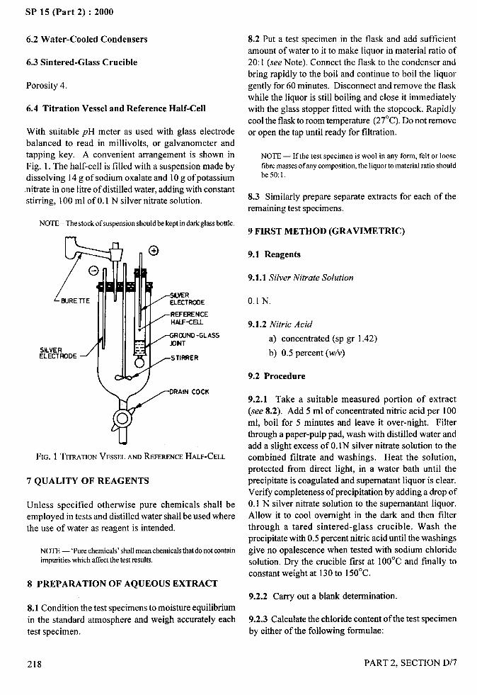
. ,,?
SP 15 (Part 2) :2000
6.2 Water-Cooled Condensers
6.3 Sintered-Glass Crucible
Porosity 4.
6.4 Titration Vessel and Reference Half-Cell
With suitable pH meter as used with glass electrode
balanced to read in millivolts, or galvanometers andtapping key. A convenient arrangement is shown in
Fig. 1. The half-cell is filled with a suspension made by
dissolving 14 g of sodium oxalate and 10 g of potassium
nitrate in one litre of distilled water, adding with constant
stirring, 100 ml of 0.1 N silver nitrate solution.
NOTE– The stock of suspensionshouldbe kept in darkglassbottle.
8.2 Put a test specimen in the flask and add sufficient
amount of water to it to make liquor in material ratio of
20:1 (see Note). Connect the flask to the condenser and
bring rapidly to the boil and continue to boil the liquor
gently for 60 minutes. Disconnect and remove the flask
while the liquor is still boiling and close it immediately
with the glass stopper fitted with the stopcock. Rapidly
cool the flask to room temperature (27°C). Do not remove
or open the tap until ready for filtration.
NOTE — If the test specimen is wool in any form, felt or loosetibre massesof any composition, the liquor to material ratio shouldbe50:l.
8.3 Similarly prepare separate extracts for each of the
remaining test specimens.
9 FIRST METHOD (GRAVIMETRIC)
YRAIN COCK
ou
FIG. 1 TImTION VESSELANDREFERENCEHALF-CELL
7 QUALITY OF REAGENTS
Unless specified otherwise pure chemicals shall be
employed in tests and distilled water shall be used where
the use of water as reagent is intended.
NOTE — ‘Purechemicals’shallmean chemicatsthat do not containimpuritieswhich affectthe test results.
8 PREPARATION OF AQUEOUS EXTRACT
8.1 Condition the test specimens to moisture equilibrium
in the standard atmosphere and weigh accurately each
test specimen.
9.1 Reagents
9.1.1 Silver Nitrate Solution
0.1 N.
9.1.2 Nitric Acid
a) concentrated (sp gr
b) 0.5 percent (w/v)
9.2 Procedure
1.42)
9.2.1 Take a suitable measured portion of extract
(see 8.2). Add 5 ml of concentrated nitric acid per 100
ml, boil for 5 minutes and leave it over-night. Filter
through a paper-pulp pad, wash with distilled water and
add a slight excess of O.lN silver nitrate solution to the
combined filtrate and washings. Heat the solution,
protected from direct light, in a water bath until the
precipitate is coagulated and supematant liquor is clear.
Verify completeness of precipitation by adding a drop of
0.1 N silver nitrate solution to the supemantant liquor.
Allow it to cool overnight in the dark and then filter
through a tared sintered-glass crucible. Wash the
precipitate with 0.5 percent nitric acid until the washings
give no opalescence when tested with sodium chloride
solution. Dry the crucible first at 10O°C and finally to
constant weight at 130 to 150”C.
9.2.2 Carry out a blank determination.
9.2.3 Calculate the chloride content of the test specimen
by either of the following formulae:
.—
218
/
PART 2, SECTION D/7

. .—SP 15 (Part 2) :2000
a) For materials in yarn and fabric form other than
wool (see Note 1):
495 x (xl -B)p=
v
b) For wool in any textile form and for felts andloose fibre masses of any composition (seeNote 2) :
1237x(.4-B)p.
vwhere
P = percentage, by weight, of water-soluble chlorideas chloride ion;
A = weight, in g, of the precipitate obtained in thetest (see 9.2.1);
B = weight, in g, of the precipitate obtained in blank(see 9.2.2); and
V = volume, in ml, of the extract taken for the test(see 9.2.1).
NOTES1 100 ml of extract is equivalent to 5.0 g of conditioned test
specimen.
2 100 ml of extract is equivalent to 2.0 g of conditioned testspecimen.
9.2.4 Repeat the test with the extracts of the remainingtest specimens.
9.2.5 Calculate the average of the values obtained asin 9.2.3 and 9.2.4.
10 SECOND METHOD (VOLUMETRIC)
10.1 Reagents
10.1.1 Standard Silver Nitrate Solution
0“1 N.
10.1.2 Standard Potassium Thiocyanate Solution
0.1 N.
10.1.3 Ferric Alum Indicator Solution
Dissolve 100 g of ferric ammonium sulphate in 250 mlof water. Heat the solution to boiling and addconcentrated nitric acid (sp gr 1.42) slowly until thered colour disappears.
NOTE— The amount of nitric acid used should be between
6 and 15ml.
10.2 Procedure
10.2.1 Take a suitable measured portion of extract.Acidify it with 5 ml of nitric acid. Add 5 ml of 0.1 Nsilver nitrate solution and 5 ml ferric alum indicatorsolution. Add sufficient amount of nitrobenzene(see Note). Titrate the excess of the silver nitrate against0.1 N potassium thiocyanate solution till the firstappearance of faint pink colour.
NOTE—About I ml ofnitrobenzene is required in every 0.05 g ofchloride.
10.2.2 Calculate the chloride content of the testspecimen by either of the following formulae:
a) For materials in yarn and fabric form other thanwool (see Note 1):
(AB -CD) X 3.55 x Z.p.
v
b) For wool in any textile form and for felts andloose fibre masses of any composition (see
Note 2):
(AB - CD) X 3.55 x sop.
vwhere
P = percentage, by weight, of water-soluble chlorideas chloride ion;
A = volume, in ml, of silver nitrate solution;B = normality of silver nitrate solution;
C = volume, in ml, of potassium thiocyanate,required for back titration;
D = normality of potassium thiocyanate solution;and
V= volume in ml, of extract taken for test.
NOTES1 100 ml of extract is equivalent to 5.0 g of conditioned test
specimen.
2 100 ml of extract is equivalent to 2.0 g of conditioned testspecimen.
10.2.3 Repeat the test with the extracts of the remainingtest specimens.
10.2.4 Calculate the average of the results obtained asin 10.2.2 and 10.2.3.
11 THIRD METHOD (POTENTIOMETRICTITRATION)
11.1 Reagents
11.1.1 Silver Nitrate Solution
0.01 N
.. ----‘1>“
,
;.,
PART 2, SECTION D/7
/
219
...
SP 15 (Part 2) :2000
11.1.2 Nitric Acid
Concentrated (sp gr 1.42).
11.2 Procedure
11.2.1 Take a suitable measured portion of the extract(see 8.2). Add 5 ml of concentrated nitric acid per100 ml of extract and boil for five minutes. Cool rapidlyto room temperature and transfer to the titration vessel.Start the stirrer, connect the electrodes to the pH meterbalanced to read in millivolts and titrate with 0.01 Nsilver nitrate solution until the galvanometers firstindicates zero.
11.2.2 Carry out a blank determination.
NOTE -—Flc{brcCA test, it shoold be veriiiedthatallpartsoftheapparatus are clean. The silver electrodes should be cleaned withvery tineabrmivcor a suitablechemicalmethod. Discardandreplacethe silver crxalatcsospcnsion at the first sign of darkening, aod todelay darkening half-cellshoold be shielded fromlightwhen not inUSC.Tbe sospcnsioo bottle should be shaken thoroughly beforereplenishingthe bzdf-cell.Take particular care that electrolytes donot come into contact with the junction between the silver wireelectrodes and their leads to the ,oIi meter. FILIShthe electrolytejunction atier each determinationby easingthe stopperat the bottomof tbc Imlfceil to allow lresh extract suspension to flow interthejunction.
11.2.3 Calculate the chloride content of the test specimen
by either of the following formulae:
a)
h)
For materials in yarn and fabric form, other
than wool (see Note 1):
~=().71X(VI-V2)
v
For wool in any textile form and for felts andloose fibre masses of any composition (seeNote 2)
~= 1.77x (VI–’VZ)
v
where
p. percentage, by weight, of chloride content as
chloride ion;
volume, in ml, of 0.01 N silver nitrate solution
required for test (see 11.2.1);
volume, in ml, of O.01 N silver nitrate solution
required for blank (see 11.2.2); and
volume, in ml, of extract taken for the test.
NOTES
I 100 ml ofthc extract is equivalent to 5.0 g ofcooditioned testspecimen.
2100 ml nftbe extract is equivalent to 2.0 g of conditioned testspecimen.
2.4 Repeat the test with the extracts of the11.
remaining test specimens and calculate the percentage
of water-soluble chloride in each test specimen.
11.2.5 Calculate the average of the values obtained as
in 11.2.3 and 11.2.4.
12 REPORT
12.1 Report the value obtained as in 9.2.5, 10.2.4
or 11.2.5 as the percentage of water-soluble chloride
as chloride ions in textile materials.
NOTE— If the percentage of the water-soluble chlorides is to beexpressedas sodium chloride. then multiply p by 1.65.
12.2 Report also the method used (whether gravimetric,
volumetric or potentiometric titration.)
/
PART 2, SECTION D/7
SP 15 (Part 2) :2000
ESTIMATION OF RESIDUALCHLORINE IN COTTON TEXTILE MATERIALS
(&M’CC : 1S 2350: 1963)
In the cotton textile industry, cotton in the form of tibres, yarn and fabric is treated with different oxidizing agentsduring the various chemical processing treatments. Garments inclusive of those made from fabrics which havebeen given a crease-resistant finish are also treated with the oxidizing agents during the laundering process.Normally, solutions of sodium or calcium hypocblorite are used as oxidizing agents. The unreacted hypochloritepresent in the material after the oxidizing treatment is completed, is removed from it by washing and/or antichlortreatments. However, some chlorine is retained by the material either due to improper washing and antichlortreatments or due to the absence of the antichlor treatments. This residual chlorine present on the material makesit yellow on storage and also degrades it if the latter comes in contact with a hot surface, for example, during
drying or ironing.
The method of test prescribed here consists of suspending the cotton textile material treated with a hypochlorite insolution of potassium iodide containing hydrochloric acid and titrating the liberated iodine against sodiumthiosulphate solution. The amount of the iodine liberated is equivalent to the available chlorine present in thecotton textile material.
1 SCOPE
It prescribes a method for estimating the residualchlorine present in cotton textile materials treated withhypochlorite solution.
2 TERMINOLOGY
For the purpose of this standard, the following definitionsshall apply.
2.1 Available Chlorine
The amount of chlorine liberated by the reaction of thematerial with acid.
2.2 Residual Chlorine
The quantity of available chlorine present in the material
at any specified period.
3 SAMPLING
3.1 Sample to estimate the residual chlorine present in
cotton textile material in a lot shall be selected so as to
be representative of the lot.
3.2 Sample drawn in compliance with an agreement
between the buyer and the seller to estimate the residual
chlorine content of the material in the lot shall be held
to be representative of the lot.
PART 2, SECTION D/8
3.3 In the absence of an agreed method of drawing
representative sample, the sample selected torepresent the lot shall consist of 100 g of the materialdrawn at random from the material constituting thelot.
4 TEST SPECIMENS
Cut the sample under test (see 3.2 and 3.3) into smallpieces. Mix all the pieces thoroughly. Draw at leastfour specimens from these pieces, such that each
specimen weighs 2 to 5g. These specimens shallconstitute the test specimens.
5 APPARATUS
5.1 Burette – of 50 ml capacity.
5.2 Erlenmeyer Flask – of pyrex glass or similarresistant glass fitted with a glass stopper, and of 500 mlcapacity.
6 REAGENTS
6.1 Quality of Reagents
Unless specified otherwise, pure chemicals shall beemployed in the tests and distilled water shall be usedwhere the use of water as a reagent is intended.
NOTE —‘ Parechemicals’shalImean clwmicalsthat do not containimpuritieswhich afTectther results of analysis.
221
/1!1
. ,4
.-
SP 15 (Part 2) :2000
6.2 Standard Sodium Thiosulphate Solution
0.01 N, prepared from sodium thiosulphate conformingto 1S 246:1986 ‘Sodium thiosulphate, crystalline,photographic grade’.
6.3 Starch Solution
0.2 percent (w/v).
6.4 Hydrochloric Acid
0.1 N, prepared from hydrochloric acid conforming to
IS 265:1993 ‘Hydrochloric acid’.
6.5 Potassium Iodide
7 PROCEDURE
7.1 Determine the moisture content, percent, of thematerial as follows.
7.1.1 Take a test specimen (see 4). Determine itsmoisture content, percent, by the method prescribed in
5 of IS 199:1989 ‘Method for estimation of moisture,total size or finish, ash, and fatty matter in grey andfinished cotton textile materials’ as given in sectionD125 .
7.1.2 Determine similarly the moisture content, percent,on a second test specimen.
7.1.3 Calculate the mean of the two values obtained as
in 7.1.1 and 7.1.2 and take that to be the moisturecontent, percent, of the material in the lot.
7.2 Take one test specimen and weigh it accurately.
Transfer the test specimen to the flask (see 5.2). Add190 ml of water, 10 ml of 0.1 N hydrochloric acid and2 g of potassium iodide to the flask. Stopper the flask
and shake it gently to mix the contents thoroughly andallow the contents to stand for one hour at room
temperature. At the end of the period, titrate theliberated iodine against 0.01 N thiosulphate solution
(see 6.2). When the colour of the solution in the flaskis pale-yellow, add 2 ml of the starch solution to it andcontinue the titration dropwise until the blue colour ofthe solution just disapears. This shall be taken as theend point.
7.3 Carry out a blank titration following the sameprocedure (see 7.2) but without the test specimen.
7.4 Calculate the residual chlorine in the test specimen
as the percent available chlorine, by the followingformula:
Residual chlorine =expressed as percentavaiiable chlorineof the test specimen
where
quantity,
(V, -V, )X NXO. O3546X1OOOO
FV(lOO- M)
in millilitres, of thiosulphatesolution required for the specimen;
quantity, in millilitres, of thiosulphatesolution required for the blank;
normality of thiosulphate solution;
Weight in g of the test specimen; and
moisture content, percent, of the materialin the lot.
7.5 Repeat the test (see 7.2 and 7.3) with the remainingtest specimen(s) and calculate the residual chlorine inthe test specimen(s) as the percent available chlorine ofthe test specimen(s).
8 REPORT
Report the mean of all the values obtained (see 7.4and 7.5) as the residual chlorine present in the cottontextile material expressed as percent available chlorineof the material in the lot.
..-
;<.:
222
/
PART 2, SECTION D/8
.’+-..”-
SP 15 (Part 2)
DETERMINATION OF SMALL QUANTITIES OF COPPER, IRON, :
MANGANESE, CHROMIUM AND ZINC IN TEXTILE MATERIA I S
(Source: IS 1039: 1989)~
~,...-,>
The presence of metals (such as copper, iron, manganese, chromium and zinc) even in small quantities, rubberized,oil-coated or similarly proofed cotton fabrics (or in basic fabric intended to be proofed) tender the fabric on reactionwith cellulose or otherwise deteriorate it. The methods prescribed are applicable in estimating metals when presentindividually or in combination with others. Every precautions should be taken to protect the fabric being sampled,the samples and the apparatus and reagents used, from adventitious contamination both before and during the testand chemicals of the analytical reagents grade and absolutely clean apparatus should be used.
The accuracy of the methods prescribed depends to a large extent on the ability of analyst and use of pure chemicals.
1 SCOPE
1.1 It prescribes methods for the estimation of smallquantities of copper, iron, manganese, chromium and
zinc in all kinds of textiles.
1.2 The methods of test prescribed in this standard are
applicable only if the total quantity of all the metalspresent does not exceed 0.2 percent (m/v) in any one of
the test solutions or suspensions.
2 SAMPLING
The sample from the lot shall be drawn so as to berepresentative of the lot. Sample drawn in accordancewith the procedure specified in relevant material
specification or as agreed to between the buyer and the
seller shall be taken as representative of the lot.
3 PREPARATION OF TEST SPECIMEN
The test sample shall be constituted of pieces or swatches
of approximately one square metre. From each suchswatch, four test specimens, 7.5 cm x 7.5 cm each, shall
be cut out from random locations. All the test specimens
shall then be shredded into fine fragments and mixed
thoroughly.
4 APPARATUS
4.1 Fiat Bottomed Canical Flasks with Neck
Extensions, of 150 ml or 250 ml capacity.
4.2 Sintered Porcelain Crucibles, of appropriate
capacity.
4.3 A Muffle Furnace
PART 2, SECTION D/9
4.4 Spectrophotometer or Spekker Absorptiometer
or Calorimeter
4.5 Hot Plate, with provision for maintaining gradedsurface temperatures.
4.6 Safety Glass Screen
4.7 Boiling Rods, made by rotating suitable lengths of5 mm diameter glass tubing in a small flame impingingabout 10 mm from one end, until the wall at that pointis completely fused leaving a small cup beyond. Thiscup is immersed in the liquid when the rod is in use.
5 QUALITY OF REAGENTS
Unless specified otherwise, pure chemicals shall beemployed in tests and distilled water shall be used wherethe use of water as a reagent is intended.
NOTE — ‘Purechemicals’shallmean chemicalsthat do not containimpuritieswhich affectthe test results.
6 ESTIMATION OF COPPER (Cu)
6.1 Destruction of the Organic Matter
6.1.1 Method 1- Wet Ashing
This method is preferable to Method 2, particularly when
the amount of copper is very small, or when substances
containing silicon (fa~ example, china clay) aye present.
Prepare wet ash of the test specimen by the method
prescribed in Annex A. Also prepare a ‘blank’ by
evaporating appropriate quantities of the acids to about
the same volume as that of the
combustion. Take particular carecompletely from both solutions.
residue from the
to expel chlorineI
223
I
, II
SP 15 (Part 2) :2000
6.1.2 Method 2- Dq Ashing
Determine the mass of the test specimen before ashing,place in a porcelain crucible and impregnate with 5
percent solution of magnesium nitrate at the rate of 1ml per gram of the test specimen. Alcohol maybe usedto facilitate the impregnation of grey cotton or poorlywettable materials. Take care to ensure that the innersurfaces of the curcible have not been damaged orroughened as this may lead to loss of copper bycombination with the glaze. Prepare dry ash of the testspecimen as prescribed in IS 199:1989 (see SectionD/25) and dissolve the ash by heating on a water-bathwith 5 ml of 2N sulphuric acid and prepare a ‘blank’ bymixing 5 ml of the same acid with the appropriatequantity of magnesium nitrate.
6.2 Selection of Method
6.2.1 The dithizone method (Method B) is moresensitive, but the choice depends largely upon the amountand nature of other substances present; the effects ofdifferent extraneous ions are summarized in Table 1.The amounts given in COI2 are the largest considered
likely to be derived from a 2 g sample of the material.The expression ‘no interference’ in COI3 and 4 signifiesthat at least this amount of the ion in question may betolerated. Interactions between different extraneous ionsare not considered.
6.3 Determination
6.3.1 MethodA - With sodium diethyldithiocarbamate.
6.3.1.1
a)
b)
224
Reagents
Sodium diethyldithiocarbamate — 0.2 percent
solution
This solution is best prepared in smallquantities at weekly intervals and should befiltered before use.
Ammonium citrate 20 percent solution
Dissolve 16 g citric acid in water and addammonium hydroxide solution (relative density0.880) until the solution is just acid to litmuspaper. Dilute the cooled solution to 100-mland shake it in a separating funnel with a smallamount of an approximately 0.01 percentsolution of dithizone in carbon tetrachloride,further quantities of this being added, if
c)
6.3.1.2
necessary, until the solvent layer remains green,blue or violet after the mixture has been shaken
vigorously for 2 minutes. Separate the solventlayer and shake the aqueous layer withsuccessive small amounts of purified carbontetrachloride (see below) until the solventremains colorless. Filter the reagent to removedroplets of the solvent.
Carbon tetrachloride
Fresh supplies of the solvent may containcarbon disulphide and should be purified asfollows:
Add alcoholic potassium hydroxide solution,with shaking, until no further yellow colourdevelops. Allow the mixture to stand for 1 hour,wash it several time with water and treat asdescribed below.
Used carbon tetrachloride that has accumulatedfrom previous analysis, or new solvent that has
been partly purified as above, shall be shakenwith successive portions of concentrated
sulphuric acid until the acid layer remainscolorless. Then shake the solvent withpowdered calcium hydroxide until evaporationof a test sample on litmus paper shows that itis free from acid, Finally filter it throughWhatrnan filter paper No. I and distil it.
Procedure
Place 10 ml of ammonium citrate solution and a fewdrops of phenolphthalein indicator in a 100-mlseparating funnel, add the ash solution (see 6.1 ) or asuitable aliquot containing not more than 150 pg ofcopper, and dilute the mixture to about 30 ml withwater. Gradually run in ammonium hydroxide solutionof any convenient strength until a permanent faint pinkcolour is obtained, cool the solution and add 2 ml ofsodium diethyldithiocarbam ate solution. Extract thebrown precipitate by shaking with 20 ml of carbontetrachloride.
If the presence of lead, mercuric, zinc or zirconium ionsis suspected, add further quantities of sodiumdiethlydithiocarbamate solution at this point until thedepth of colour of the carbon tetrachloride layer nolonger increases. Add small amounts of the reagent inthe two subsequent extractions to ensure that all thecopper has reacted. Do not carry out the extractions in
PART 2, SECTION D/9
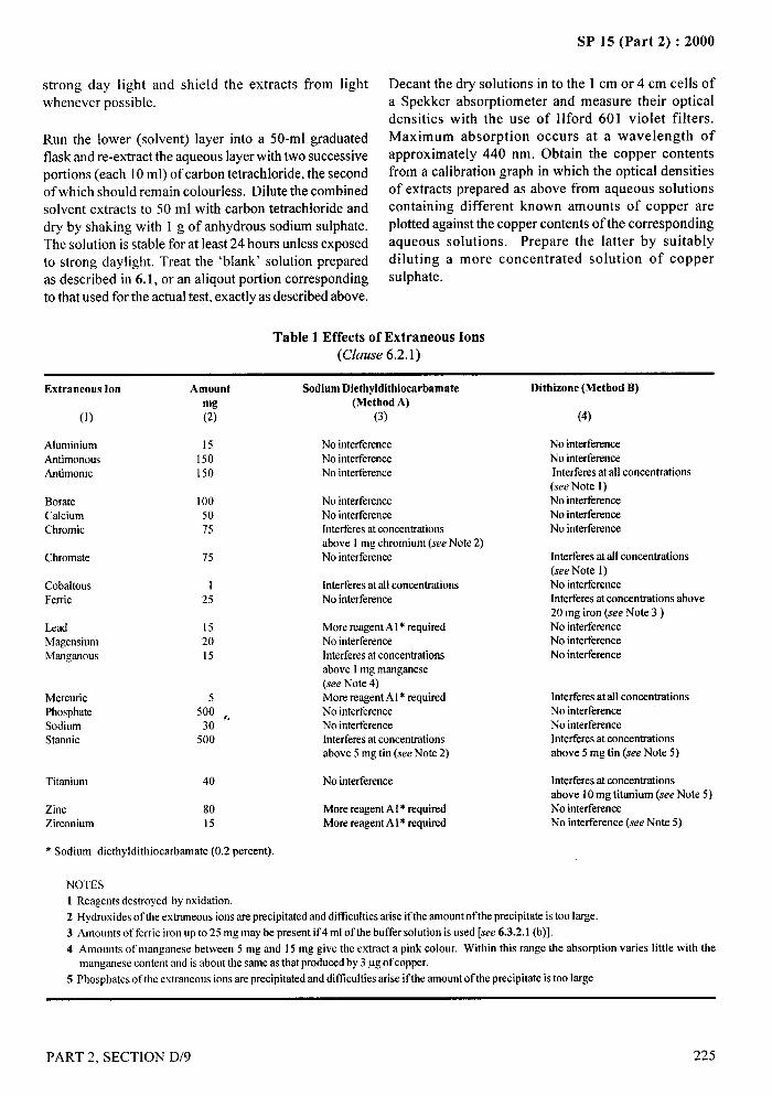
SP 15 (Part 2) :2000—
strong day Iight and shield the extracts from lightwhenever possible.
Run the lower (solvent) layer into a 50-ml graduatedflask and re-extract the aqueous layer with two successiveportions (each 10 ml) of carbon tetrachloride, the secondof which should remain colorless. Dilute the combinedsolvent extracts to 50 ml with carbon tetrachloride anddry by shaking with 1 g of anhydrous sodium sulphate.The solution is stable for at least 24 hours unless exposedto strong daylight. Treat the ‘blank’ solution preparedas described in 6.1, or an aliqout portion correspondingto that used for the actual test, exactly as described above.
Decant the dry solutions into the 1 cm or 4 cm cells ofa Spekker absorptiometer and measure their opticaldensities with the use of Ilford 601 violet filters.Maximum absorption occurs at a wavelength ofapproximately 440 nm. Obtain the copper contentsfrom a calibration graph in which the optical densitiesof extracts prepared as above from aqueous solutionscontaining different known amounts of copper areplotted against the copper contents of the correspondingaqueous solutions. Prepare the latter by suitably
diluting a more concentrated solution of coppersulphate.
Table 1 Effects of Extraneous Ions(Clause 6.2.1)
Extraneous Ion Amount
mg(2)
Sodium Diethyldithioearbamate(Method A)
(3)
Dithizone (Method B)
(1) (4)
AhrminiumAntimonousAntimonic
15150150
No interferenceNo interferenceNo interference
No interferenceNo interferenceInterferw at all concentrations(see Note 1)No interferenceNo interferenceNo interference
BorateCalciumChromic
1005075
No interferenceNo interferenceInterferesat concentrationsabove 1 mg chromium (see Note 2)No interferenceChromate 75 Interferesat all concentrations
(see Note 1)No interferenceInterferesat concentrations above20 mg iron (see Note 3 )No interferenceNo interferenceNo interference
CobaltousFerric
I25
Interferesat all concentrationsNo interference
s“LeadMagensiumManganous
152015
More reagentAl* requiredNo interferenceInterferesat concentrationsabove 1mg manganese(see Note 4)More reagentAl* requiredNo intefierenceNo interferenceInterferesat concentrationsabove 5 mg tin (see Note 2)
Interferesat all concentrationsNo interferenceNo interferenceInterferesat concentrationsabove 5 mg tin (see Note 5)
Mercuric 5Phosphate 500 ,.Sodium 30Stannic 500
No interference Interferesat concentrationsabove 10mg titanium (see Note 5)No interferenceNo interference (see Note 5)
Titanium 40
Zinc 80Zirconium 15
More reagentAl* requiredMore reagentAl* required
* Sodium diethyldithiocarbamate (0.2 percent)
NOTES1 Reagents destroyed by oxidation.2 Hydroxides of the extraneous ions are precipitated and difilculties arise if the amountof the precipitate istoo large.3 Amounts of ferric iron up to 25 mg may be present if 4 ml of the buffer solution is used [see 6.3.2.1 (b)].4 Amounts of manganese between 5 mg and 15 mg give the extract a pink colour. Within this range the absorption varies little with the
manganese content and is about the same as that producedby 3 pg of copper.5 Phosphates of the extraneous ions are precipitated and difficultiesarise if tbe amountof the precipitate is too large
PART 2, SECTION D/9 225
I!’
/
SP 15 (Part 2) :2000
Any other absorptiometer or calorimeter may be used,or the colours of the extracts maybe compared visually,in tubes of uniform dimensions, with those of a series of
extracts freshly prepared from solutions of known coppercontent. These alternatives may, however, affect themaximum permissible amount of copper in the solutiontaken for extraction.
6.3.2 Method B – With diphenylthiocarbazone(dithizone).
6.3.2.1
a)
b)
c)
6.3.2.2
Reagents
Dithizone, 0.002 percent solution in purljled
carbon tetrachloride - Prepare the solutiondaily and purify as follows:
Shake 10 ml of a 0.02 percent stock solution ofdithizone in purified carbon tetrachloride in a
separating funnel with 20 ml of watercontaining a drop of dilute ammoniumhydroxide solution. Reject the yellowish-
brown solvent layer and shake the aqueouslayer with a small amount of carbon
tetrachloride, which is also rejected. Add 100ml of carbon tetrachloride and then sufficientdilute hydrochloric acid to precipitate all thedithizone from the aqueous layer. Dissolve theprecipitate in the solvent by shaking and runthe solution off through a plug of loose cottonwool inserted in the stem of the funnel toremove droplets of water.
If stored in a stoppered vessel in a cool, darkplace the reagent is sufficiently stable for oneday’s work. Under similar conditions the 0.02percent stock solution may be kept for about aweek.
Bu& solution
Dissolve 75 g citric acid and 19 g anhydroussodium dihydrogen phosphate in water. Dilutethe mixed solution to 250 ml and purify it
exactly as described for the ammonium citratesolution.
Tropaeolin 00, 0.1 percent aqueous solution
Dksolve 0.1 g of the solid in 100 ml of water.
Procedure
Place 2 ml of the buffer solution in a 50 ml separatingfunnel, add the ash solution (see 6.1) or a suitable aliquot
226
containing not more than 10 pg of copper, and dilutethe mixture to about 20 ml with water. Add ammonium
hydroxide solution (relative density 0.880) gradually
until the mid hue of the indicator is reached, cool thesolution and add 10.0 ml of dithizone solution by meansof a pipette. Shake the funnel steadily for 2 minutes
(about 240 strokes). The colour of the lower (solvent)layer should now be green, blue or violet. If it is violet-red add a fimther quantity (10.0 ml) of dithizone solution
and repeat the shaking.
Run the solvent layer into another separating funneland shake for 30 seconds with 10 ml of 0.1 N
hydrochloric acid (see Note 1). If it is then still redreject it and repeat the determination with a smaller
aliquot of the original solution. Otherwise, draw it
off through a small tuft of cotton wool inserted in thestem of the funnel to remove droplets of water and
collect it in a 1 cm cell of the Spekker absorptiometer.Treat the ‘blank’ solution, prepared as described in6.1, or an aliquot portion corresponding to that usedfor the actual determination exactly as describedabove.
Measure the optical densities of the extracts with theuse of green filters. Maximum absorption of the
copper complex occurs at about 550 nm, but it ispreferable to make measurements at 510 nm wherethe absorption of the unchanged dithizone is at aminimum. The difference between the optical
densities of the ‘test’ and ‘blank’ extracts is used toobtain the copper content directly from a calibrationgraph constructed as follows.
Extract a series of solutions containing differentmeasured amounts of a standard solution of coppersulphate as above and measure the optical densities ofthe extracts. Subtract from each value the optical density
of the extract from a similar solution containing no addedcopper and plot the differences against the coppercontents of the original solutions. These differences aresubstantially independent of the concentration of thedithizone solution within the range 0.001 5 percent to
0.0025 percent.
Any other absorptiometer may be used, or the colourof the extract and those of extracts prepared similarlyfrom a series of aqueous solutions containing knownamounts of copper may be compared visually in small
stoppered tubes of uniform dimensions. It is notpossible to make the comparison in calorimeters of theDuboseq type. The colours are stable for few hours ifthe solutions are protected from light.
PART 2, SECTION D/9
.—-
/
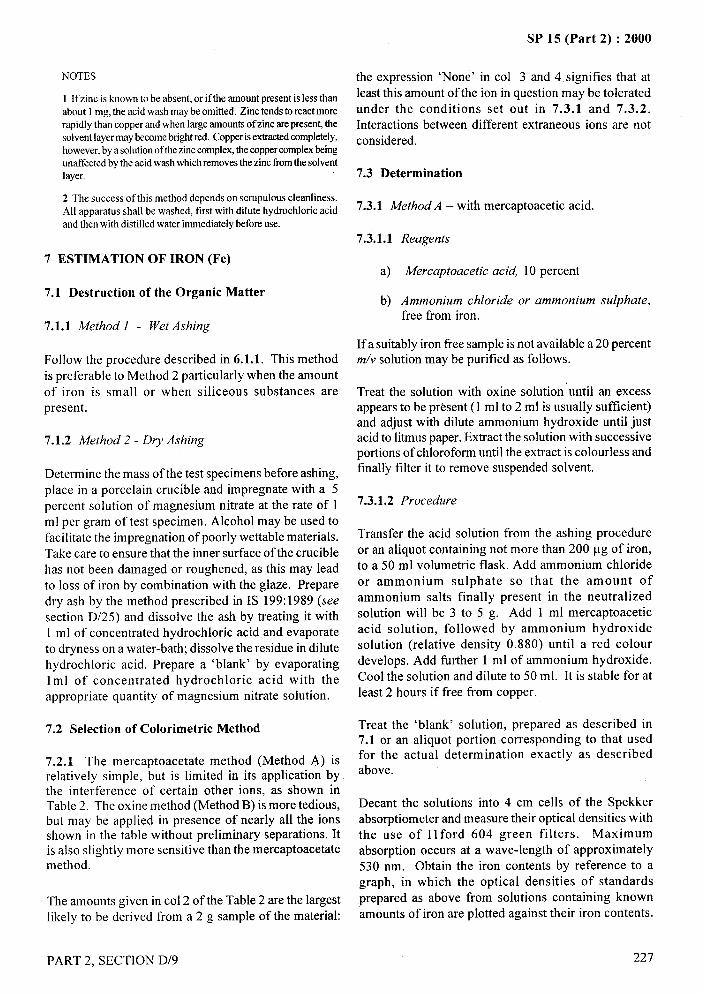
NOTES
1 Ifzinc is known to be absent, or ifthe amountpresent is less thanabout 1mg, the acid wash maybe omitted. Zinc tendsto reactmorerapidly than copper andwhen largeamountsof zinc arepresent,thesolventlayermaybecxxnebrightred. Copperisextractedcompletely,however,by a solutionofthezinccomplex,the coppercomplexbeingunaffectedby the acidwashwhichremovesthe zinc fromthe solventlayer.
2 The success of this method depends on scrupulous cleanliness.All apparatus shall be washed, first with dilute hydrochloric acidand then with distilledwater immediatelybeforeuse.
7 ESTIMATION OF IRON (Fe)
7.1 Destruction of the Organic Matter
7.1.1 Method 1 - Wet Ashing
Follow the procedure described in 6.1.1. This methodis preferable to Method 2 particularly when the amount
of iron is small or when siliceous substances arepresent.
7.1.2 Method 2- Dry Ashing
Determine the mass of the test specimens before ashing,
place in a porcelain crucible and impregnate with a 5percent solution of magnesium nitrate at the rate of 1ml per gram of test specimen. Alcohol may be used tofacilitate the impregnation of poorly wettable materials.Take care to ensure that the inner surface of the cruciblehas not been damaged or roughened, as this may leadto loss of iron by combination with the glaze. Preparedry ash by the method prescribed in IS 199:1989 (seesection D/25) and dissolve the ash by treating it with1 ml of concentrated hydrochloric acid and evaporateto dryness on a water-bath; dissolve the residue in dilutehydrochloric acid. Prepare a ‘blank’ by evaporatinglml of concentrated hydrochloric acid with theappropriate quantity of magnesium nitrate solution.
7.2 Selection of Calorimetric Method
7.2.1 The mercaptoacetate method (Method A) isrelatively simple, but is limited in its application bythe interference of certain other ions, as shown inTable 2. The oxine method (Method B) is more tedious,but may be applied in presence of nearly all the ionsshown in the table without preliminary separations. Itis also slightly more sensitive than the mercaptoacetatemethod.
The amounts given inCO12 of the Table 2 are the largestlikely to be derived from a 2 g sample of the material:
SP 15 (Part 2) :2000
the expression ‘None’ in CO1 3 and 4 signifies that atleast this amount of the ion in question maybe toleratedunder the conditions set out in 7.3.1 and 7.3.2.Interactions between different extraneous ions are not
considered.
7.3 Determination
7.3.1 Method A – with mercaptoacetic acid.
7.3.1.1
a)
b)
Reagents
A4ercaptoacetic acid 10 percent
Ammonium chloride or ammonium sulphate,free ffom iron,
If a suitably iron free sample is not available a 20 percentmlv solution may be purified as follows.
Treat the solution with oxine solution until an excessappears to be present (1 ml to 2 ml is usually sufficient)and adjust with dilute ammonium hydroxide until justacid to litmus paper. Extract the solution with successiveportions of chloroform until the extract is colorless andfinally filter it to remove suspended solvent.
7.3.1.2 Procedure
Transfer the acid solution from the ashing procedureor an aliquot containing not more than 200 pg of iron,to a 50 ml volumetric flask. Add ammonium chloride
or ammonium sulphate so that the amount ofammonium salts finally present in the neutralizedsolution will be 3 to 5 g. Add 1 ml mercaptoaceticacid solution, followed by ammonium hydroxidesolution (relative density O.880) until a red colourdevelops. Add further 1 ml of ammonium hydroxide.Cool the solution and dilute to 50 ml. It is stable for atleast 2 hours if free from copper.
Treat the ‘blank’ solution, prepared as described in7.1 or an aliquot portion corresponding to that usedfor the actual determination exactly as describedabove.
Decant the solutions into 4 cm cells of the Spekkerabsorptiometer and measure their optical densities withthe use of Ilford 604 green filters. Maximumabsorption occurs at a wave-length of approximately530 nm. Obtain the iron contents by reference to agraph, in which the optical densities of standardsprepared as above from solutions containing knownamounts of iron are plotted against their iron contents.
PART 2, SECTION D/9
/
227
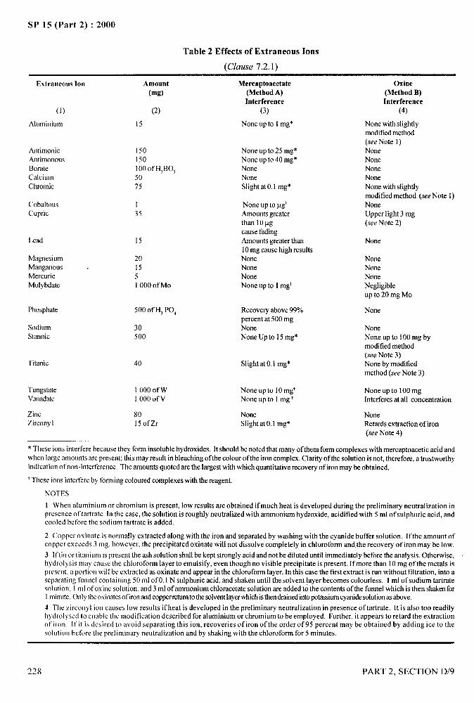
SP 15 (Part 2) :2000
Table 2 Effects of Extraneous Ions
(Clause 7.2.1)
Extraneous Ion Amount(mg)
Mercaptoacetate(Method A)Interference
(3)
Oxine(Method B)Interference
(4)(1)
Aluminiuln
(2)
15 None up to 1mg* None with slightlymoditiedmethod(see Note 1)NoneNooeNoneNoneNone with slightlymodified method (see Note 1)NoneUpper light 3 mg(see Note 2)
AntirnonicAntirnonousBorateCalciumChromic
I 50150100 of HIBO,5075
None up to 25 mg$None up to 40 mg*NoneNoneSlight at 0.1 mg*
CobaltousCupric
Nooe up to pg’Amountsgreaterthan 10pgcausefadingAmountsgreaterthan10mg cause high resultsNoneNoneNoneNone up to 1mgt
135
Lead 15 None
MagnesiumManganous .MercuricMolybdate
201551000 of Mo
NoneNoneNoneNegligibleup to 20 mg Mo
Phosphate 500 of H, PO, Recoveryabove99%percent at 500 mgNoneNone Up to 15mg$
None
SodiumStanoic
30500
NoneNone up to 100 mg bymodifiedmethod(see Note 3)None by modifiedmethod (see Note 3)
Titanic 40 Slight at 0.1 mg*
TungsMeVaoadate
1000 of wI 000 Ofv
None up to 10mg’None up to 1mg’
None up to 100mgInterferesat all concentration
ZincZirconyl
80150fZr
NoneSlight at0,1 mg*
NoneRetards extraction of iron(see Note 4)
* These ions interfere because they form insolublehydroxides. It should be notedthat many of them form complexeswith mercaptoacetic acid andwhen large amounts are present; this may result in bleachingof the colour of the ironcomplex.Clarity of the solution is not, therefore, a trustworthyindication of non-interference, The amounts quotedare the largestwith which quantitativerecoveryof ironmaybe obtained,
t These ions interfereby formingcoloured complexeswith the reagent.
NOTES
1 When aluminium or chromium is present, low results are obtained if much heat is developed during the preliminary neutralization inpresence of tartrate, In the case, the solution is roughly neutralized with ammonium hydroxide, acidified with 5 ml of sulphuric acid, andcooled before the sodium tartrate is added.
2 Copper oxinate is normally extracted along with the iron and separated by washing with the cyanide buffer solution. If the amount ofcopper exceeds 3 mg, boweyer, the precipitated oxinate will not dissolve completely in chloroform and the recovery of iron may be low.
3 lftio or titanium is present the ash solution shall be kept strongly acid and not be diluted until immediately before the analysis. Otherwise,hydrolysis may cause the chloroform layer to emulsify, even though no visible precipitate is present. If more than 10 mg of the metals ispresent, a portion wilIbe extracted as oxinate and appear in the chloroform layer. In this case the first extract is run without filtration, into aseparating funnel containing 50 ml of 0,1 N sulphuric acid, and shaken until the solvent layer becomes colorless. 1ml of sodium tartratesolution, 1ml of oxioe solution. and 3 ml of ammonium chloracetate solution are added to the contents of the funnel which is then shakenforI rninutc.Onlytheoxinatesof ironandcopperrchantothesolventlayerwhichisthendrainedintopotassiumcyanidesolutionasabove.
-1 The zircooyi ion causes low results if beat is developed in the preliminary neutralization in presence of tartrate. It is also too readilyhydrolyses to eaable the modification described for aluminium or chromium to be employed. Further, it appears to retard the extractionolirom If it is desired to avoid separating this ion, recoveries of iron of the order of95 percent may be obtained by adding ice to thesolution before the preliminary neutralization and by shaking with the chloroform for 5 minutes.
228 PART 2, SECTION D/9

SP 15 (Part 2) :2000
The standards may be prepared by dilution of a solution
of ferric alum in 0.1 N sulphuric acid.
Any other absorptiometer or calorimeter maybe used,or the samples maybe compared visually with freshlyprepared standards in tubes of uniform dimensions.These variations may, however, affect the maximumpermissible amount of iron in the solution
7.3.2 Method B – With S-hydroxyquinoline (oxine).
7.3.2.1 Reagents
a)
b)
c)
d)
e)
f)
7.3.2.2
Sodium tartrate 2A4 – Free a solutioncontaining 460 g of the hydrated salt perIitre from iron as described for reagent in7.3.1.1 (b).
Ammonium chloracetate 4M – Dissolvechloracetic acid (380 g) in water and neutralizewith ammonium hydroxide (relative density0.880) the solution being cooled during theprocess to reduce hydrolysis. Free the solutionfrom iron as described above for reagent in7.3.1.1 (b).
Oxine, 5 percent solution in 2M acetic acid.
Potassium Cyanide buffer – Prepare thesolution, which has a pH value of 8.5 bydissolving 0.5 g of potassium cyanide in 100ml of 0.06 N hydrochloric acid. Store this inwell stoppered bottles and reject it if it becomesdiscolored.
Chloroform - This maybe recovered by shakingfirst with successive portions of concentratedsulphuric acid until the acid layer remains
almost colorless, then with an excess ofcalcium hydroxide, filtering any finallydistilling. Add alcohol at the rate of 1 percentby volume to the distillate.
Methyl orange, 0.1 percent.
Procedure
Transfer the acid solution from the ashing procedure,or an aliquot portion containing not more that 250 ~gof iron, to a 250 ml conical flask and dilute to 30 ml.Cover the flask by a light shield (see Note 2). Add 1ml sodium tartrate solution and a few drops of methylorange indicator and neutralize the solution withconcentrated ammonium hydroxide solution. The end
PART 2, SECTION D/9
point is easily observed, without removal of the shield, ..
by holding the flask a short distance above a white tileand looking down the neck. Cool the flask rapidly inrunning water, the shield being removed temporarily
“--qjand exposure to strong daylight avoided; make anynecessary adjustment of the pH with dilute acid oralkali. Add 2.5 ml 2 N sulphuric acid, 1.0 ml oxinesolution and 3.0 ml ammonium chloracetate solutionin that order with intermediate mixing, the solution
being transfered to a 100 ml separating funnel anddiluted to about 50 ml. Add 25.0 ml chloroform andshake the contents of the funnel steadily for 2 minutes(about 300 cycles).
Drain the solvent layer through a tufi of cotton woolinserted in the stem of the funnel and collect it in another100 ml separating funnel containing 20 ml of potassium
cyanide solution. Shake this funnel for 1 minute anddrain the solvent layer through another cotton plugdirectly into a cell of the Spekker absorptiometer.Measure its optical density with the use of I ford N0.602
blue filter, maximum absorption being at about 470 lm.The extract is stable for at least 1 hour evaporation ifprevented.
Treat the ‘blank’ solution, prepared as in 7.1, or analiquot corresponding to that used for the actualdetermination, exactly as above.
Determine the iron content by reference to a calibrationgraph prepared as follows :
Dilute measured amounts of a standard solution of ,’ferric alum in 0.1 N sulphuric acid with water to 50ml and treat as described above, omittingneutralization to methyl orange. If a freshly preparedsolution of oxine is used, the ‘blank’ should showonly a very small absorption which is calculated asiron by assuming the graph near the origin to belinear. Add this amount of iron to each standard when
the graph is plotted and extrapolate the curve to theorigin. Any other absorptiometer may be used, orthe extracts may be compared visually with freshlyprepared standards in tubes of similar dimensions.These variations may, however, affect the maximumamount of iron that may be present. I
NOTES
1 All apparatus should be rinsed with dilute hydrochloric acid andthenwithwaterbefomuse. Careshouldbe takenthatno acid remainsroundthe stopcocksof separatingfunnels,and unbufferedsolutionsshould not be placed in the funnels.
2 Ferric ions in faintly acid solution containingtartrate are reducedby light, Suitablelightshields inthe form oftruncated conesmaybe
229
1
1
I I
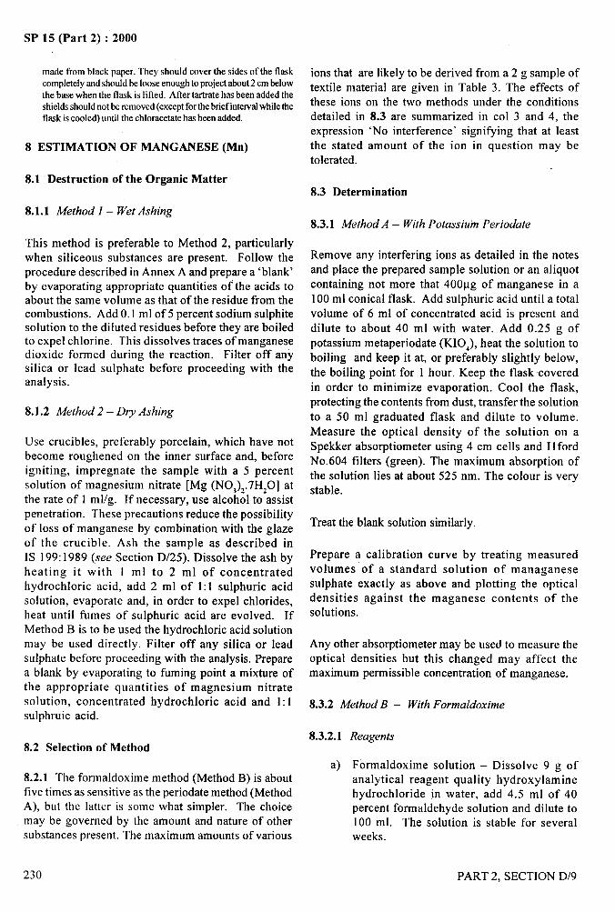
.—
SP 15 (Part 2) :2000
made from black paper. They should cover the sides of the flaskcompletelyand should be loose enoughto projectabout2 cm belowthe base when the flask is lifted. After tartrate has been added theshieldsshouldnot be removed(exceptforthe briefintervalwhiletheflask iscooled) until the chloracetate has been added.
8 ESTIMATION OF MANGANESE (Mn)
8.1 Destruction of the Organic Matter
8.1.1 Method 1 – Wet Ashing
This method is preferable to Method 2, particularlywhen siliceous substances are present. Follow theprocedure described in Annex A and prepare a ‘blank’by evaporating appropriate quantities of the acids toabout the same volume as that of the residue from thecombustion. Add 0.1 ml of 5 percent sodium sulphitesolution to the diluted residues before they are boiledto expel chlorine. This dissolves traces of manganesedioxide formed during the reaction. Filter off anysilica or lead sulphate before proceeding with theanalysis.
8.1.2 Method 2 – Dry Ashing
Use crucibles, preferably porcelain, which have notbecome roughened on the inner surface and, beforeigniting, impregnate the sample with a 5 percentsolution of magnesium nitrate [Mg (NOJ)2.7HZO] atthe rate of 1 ml/g. If necessary, use alcohol to assistpenetration. These precautions reduce the possibility
of loss of manganese by combination with the glazeof the crucible. Ash the sample as described inIS 199:1989 (see Section D/25). Dissolve the ash byheating it with 1 ml to 2 ml of concentratedhydrochloric acid, add 2 ml of 1:1 sulphuric acidsolution, evaporate and, in order to expel chlorides,heat until fumes of sulphuric acid are evolved. IfMethod B is to be used the hydrochloric acid solutionmay be used directly. Filter off any silica or leadsulphate before proceeding with the analysis. Preparea blank by evaporating to fuming point a mixture ofthe appropriate quantities of magnesium nitratesolution, concentrated hydrochloric acid and 1:1sulphruic acid.
8.2 Selection of Method
8.2.1 The formaldoxime method (Method B) is aboutfive times as sensitive as the periodate method (MethodA), but the latter is some what simpler. The choicemay be governed by the amount and nature of othersubstances present. The maximum amounts of various
230
ions that are likely to be derived from a 2 g sample of
textile material are given in Table 3. The effects ofthese ions on the two methods under the conditionsdetailed in 8.3 are summarized in CO13 and 4, theexpression ‘No interference’ signifying that at least
the stated amount of the ion in question may betolerated.
8.3 Determination
8.3.1 Method A – With Potassium Periodate
Remove any interfering ions as detailed in the notesand place the prepared sample solution or an aliquotcontaining not more that 400pg of manganese in a
100 ml conical flask. Add sulphuric acid until a totalvolume of 6 ml of concentrated acid is present and
dilute to about 40 ml with water. Add 0.25 g of
potassium metaperiodate (KIO,), heat the solution toboiling and keep it at, or preferably slightly below,
the boiling point for 1 hour. Keep the flask coveredin order to minimize evaporation. Cool the flask,
protecting the contents from dust, transfer the solution
to a 50 ml graduated flask and dilute to volume.
Measure the optical density of the solution on aSpekker absorptiometer using 4 cm cells and 11ford
No.604 filters (green). The maximum absorption ofthe solution lies at about 525 nm. The colour is very
stable.
Treat the blank solution similarly.
Prepare a calibration curve by treating measuredvolumes of a standard solution of manganesesulphate exactly as above and plotting the opticaldensities against the maganese contents of thesolutions.
Any other absorptiometer maybe used to measure theoptical densities but this changed may affect themaximum permissible concentration of manganese.
8.3.2 Method B – With Formaldoxime
8.3.2.1
a)
Reagents
Formaldoxime solution – Dissolve 9 g ofanalytical reagent quality hydroxylaminehydrochloride in water, add 4.5 ml of 40percent formaldehyde solution and dilute to100 ml. The solution is stable for severalweeks.
PART 2, SECTION D/9
..
1i:.,-.,
‘!
/
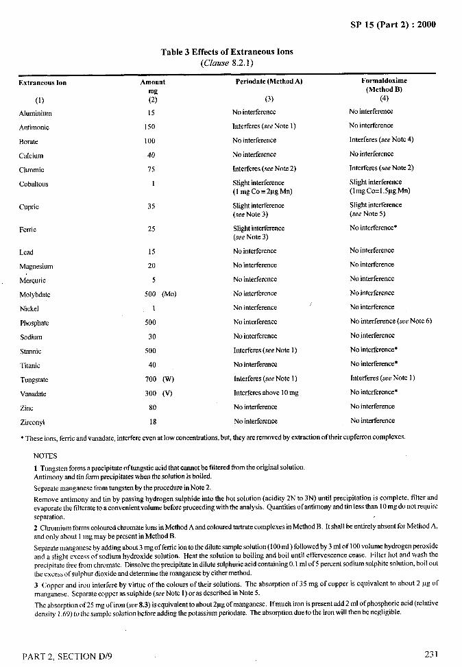
SP 15 (Part 2) :2000
Table 3 Effects of Extraneous Ions
(Clause 8.2. 1)
,6
.—
I
Extraneous Ion Amount Periodate (Method A) Formaldoxime
mg (Method B)
(1) (2) (3) (4)
Ahrminium 15 No interference No intefierence
Antimonic 150 Interferes (see Note 1) No interference
Borate 100 No interference Interferes (see Note 4)
Calcium 40 No intefierence No interference
Chromic 75 Interferes (see Note 2) Interferes (see Note 2)
Cobaltous 1 Slightinterference Slight irrterterence(lmg Co=2~g Mn) (lmg Co=l.5pg Mn)
Cupric 35 Slight interference Slight interference(see Note 3) (.reeNote 5)
Ferric 25 Slightinterference No interference*(see Note 3)
Lead 15 No interference No interference
Magnesium 20 No interference No interference
Merquric 5 No interference No interference
Molybdate 500 (MO) No interference No interference
Nickel 1 No interference/ No interference
Phosphate 500 No interference No interference (see Note 6)
Sodium 30 No interference No interference
Starmic 500 Interferes (seeNote 1) No interfererrce*
Titanic 40 No interference Nointerference*
Tungstate 700 (w) Interferes (see Note 1) Interferes (see Note 1)
Vanadate 300 (v) Interferesabove 10mg No interference*
Zinc 80 No interference No interference
Zirconyl 18 No interference No interference
* These ions, ferric and vanadate, interfereeven at low concentrations,but, they areremovedby extractionof their cupferron complexes.
NOTES
1 Tungsten forms a precipitate oftungstic acid that cannot be filtered from the original solution.Antimony and tin form precipitateswhen the solution is boiled.
Separate manganese from tongsten by the procedurein Note 2.
Remove antimony rmdtin by passing hydrogen sulphlde into the hot solution (acidity 2N to 3N) until precipitation is complete, filter andevaporatethe filterate to a convenientvolumebeforeproceedingwith the analysis. Quantitiesof antimonyand tin less than 10mg do not requireseparation.
2 Chromium forms colouredchromateions in Method A and colouredtartratecomplexesinMethod B. It shall be entirely absent for Method A,and only about 1mg maybe present in Method B.
Sepaate manganeseby addingabout3 mg of ferricionto the dilutesamplesolution(100ml ) followedby 3 ml of 100volume hydrogenperoxideand a SIi.gbtexcess of sodium hydroxide solution. Heat the solution to boiling and boil until effervescence cease. Filter hot and wash theprecipitate free from chromate. Dk.soIvetbe precipitate in dilute sulphuricacid containing0.1 ml of 5 percent sodium sulphite solution, boil outthe excessof sulphordioxide and determinethe manganeseby either method.
3 Copper and iron interfere by virtue of the colours of their solutions. The absorption of 35 mg of copper is equivalent to about 2 IIg ofmanganese. Separate copper as sulphide (seeNote 1)or as described inNote 5.
The absorption of 25 mg of iron (see 8.3) is equivalent to about2pg of manganese. Ifmuch iron is present add 2 ml of phosphoric acid (relativedensity 1.69)to the sample solution before adding the potassiumperiodate. The absorptiondue to the iron will then be negligible.
,..7
[PART 2, SECTION D/9 231
/
SP 15 (Part 2) :2000. . ..—
4 Borate ions react with the formal doxime. Use 4 ml ofa freshlypreparedformaldoximereagent five times as concentrated as that specified ifI
the presenceof borate is suspected.~+ .—.
~5 ‘Thepresenceof more than about 5 mg of coppertends to cause low recoveriesofmanganese. Separatethe copper by addingexcessof sodiumdictbyldithicarbamate solution after extracting the iron as described under Method B and continuing to extract with portions of methyiene
1
chloride until no tirther brown colour is removed.
qi“+’ “’
6 Phosphate interferes by producing a precipitates in alkaline solution inappreciableamounts of lead, clacium or magnesium are present. The I
quantities olthese metals or of phosphatenormally found in textiles cause no trouble.
Remove Icad as sulphate beforebeginningthe analysis.
lfcalcium is present add sullicient sulphuric acid to the original solutionto ensurethat the concentrationof ammonium salts in the final solutionwiIIbe 20percent to 25 percent. This will retain a considerableamountof calcium phosphate in solution.
Ifmagnesiom ispresent, add 2 g of analytical reagentquafitysodiumpyrophosphateimmediatelybefore makhrgthe solution alkaline.
b)
c)
d)
e)
o
g)
h)
Tartaric acid solution – 30 g of analyticalreagent quality acid in 100 ml.
Cupferron solution – 10 g of Cupferron in100 m 1 of water. Prepare freshly and filterbefore use.
Saturated bromine water.
Methyl orange – 0.05 percent solution in water.
Zinc cyanide solution – Dissolve 10 g of
analytical reagent quality potassium cyanide
in 50 m 1of water, and 12 g of analytical reagent
quality zinc sulphate (ZnS0,.7HzO) in 50 ml
of water. Mix and add sufficient concentrated
ammonium hydroxide to dissolve the
precipitate which forms. A small precipitate
may form on keeping the solution; decant the
supernatant liquid before use.
Methylene chloride – Recover used solvent bydistilling it in presence of about one-tenth itsvolume of 10 percent soidum hydroxidesolution.
Manganous sulphate solution – Dissolve 2.042g of manganous sulphate (MnS0,.4H20) inwater, add 1 ml of concentrated sulphuric acidand dilute to 400 ml. This solution containsapproximately 1 mg of manganese permillilitre. Standardize as follows:
Pipette 20 ml of solution into 100 ml of M sulphuricacid, add 1 g of sodium bismuthate, and allow to
1)TI,e followi,,g complexes may be extracted:ferric(brown),molybdate(white),stannic(white),titanic(yellow),wmadate(darkbrown),zircorryl(paleyellow). Increasethe initialadditionof capfemonuntilin excessif muchmetalispresent.Z)If,.opperispte~elltinqaanti~precededasdescribedinNote5aaderT*le3atthispoint.
stand for 5 min with occasional shaking. Filter ‘*,5
through a sintered glass (G4) filter or asbestos-padded Gooch crucible, rinse the residue with Msulphuric acid until free from permanganic acid and Ititrate the filtrate with fkeshly standardized ferroussulphate solution: 1 ml 0.1 N reductant = 1.099 mgof Mn. Dilute this solution as required immediatelybefore use.
8.3.2.2 Procedure
The procedure allows for the removal of the interfering ‘elements iron, tin, titanium and vanadium by extractionof their cupferron complexes and for the masking ofsmall quantities of copper, cobalt and nickel withcyanide. Remove any other interfering elements asdetailed in the Notes.
IPlace the prepared sample solution or an aliquotcontaining not more than 75 pg of manganese in a If
separating fi.mnel. Adjust the volume to about 25 ml L<and the sulphuric acid content to at least 3 N (the total %acidity should not exceed 6N). Cool if necessary, add1 ml of cupferron solution and extract with 10 ml ofmethylene chloride. Repeat this procedure until theaddition of cupferron produces only a slight precipitateof the free reagent ‘), than extract with one further 10ml portion of methylene chloride).
Transfer the aqueous solution to a suitable conical flask,rinsing the funnel with a minimum of water and add1 ml of 60 percent perchloric acid if the solution doesnot already contain this acid. Evaporate the solutionuntil fumes of perchloric acid are evolved and allorganic matter has been destroy ed3J, Cool, add 20 ml
F
v ~le ~lno,lnt~forgmicmatterremainingisverysmallandtherea@imris iw’tbouthazard.Ilreorganicmattermaybedestroyedbyprnlongeddlgesnonwithsalpharicacidaloneifpreferred.d)Wide.mgein{lcatorpaper maybe asedasexternalindicatorifpreferred.5)SeeNote4 underTable3. I
232
/
PART 2, SECTION D/9
. . ___SP Is (Part 2) :2000
of water, boil for a few minutes to remove chlorineand again cool. Add not more than 0.05 ml of methylorange solution and 1 ml of tartaric acid solution, andneutralize with concentrated ammonium hydroxidesolution.
Add 3 ml of M sulphuric acid and 0.1 ml of brominewater to destroy the indicator4J. Cool, add 2 ml ofzinc cyanide solution, 1 ml of formaldoxime solutions)and 4 ml of ammonium hydroxide (relative density0.880). Transfer the solution to a 50 ml graduatedflask and dilute to volume. Remove a few millilitresof the solution, shake the remainder vigorously andafter an interval of 30 minutes measure the opticaldensity of the solution on a Spekker absorptiometerwith 4 cm cells and Ilford No.602 filters (blue). Themaximum absorption of the solution lies at about 460nm. The colour is stable for at least 4 hours.
Prepare a calibration curve as follows:
Dilute measured amounts of a suitable standard solutionof manganous sulphate to about 40 ml. Add 1 ml oftartaric acid, 2 ml of zinc cyanide, 1 ml of formaldoximeand 3 ml of ammonium hydroxide (relative density0.880) solution. Measure the optical densities after 30minutes and plot them against the manganese contentsof the solutions.
Any other absorptiometer may be used to measure theoptical densities, but this change may alter the maximumpermissible concentration of manganese.
9 ESTIMATION OF CHROMIUM (Cr)
9.1 Destruction of the Organic Matter
9.1.1 Method 1- Wet Ashing
This method is preferable to Method 2, particularly whenthe amount of chromium is small or when siliceoussubstances or large amounts of other ions are present.The procedure is described in Annex A, but it is esentialto use sufficient sulphuric acid to cover the bottom ofthe flask at all times (see Note). The necessary amountis 2 ml for 150 ml flasks and the same amount sufficesfor 250 ml flasks if the bottoms are truly flat.
At the end of the reaction heat the flask strongly withthe neck extension still in place. When the perchloricacid has been expelled the residual acid ceases to boiland changes from yellow-green to colorless. It is notnecessary to expel every trace ofperchloric acid. Dilutethe residue boil it until free from chlorine, then cool
and neutralize it with concentrated ammoniumhydroxide solution, methyl orange (0.05 ml of a 0.1percent solution) being used as an indicator. Re-acidifithe solution with 5 ml of 2 N sulphuric acid and adjustit to a final volume of about 30 ml. Prepare a ‘blank’ byvolatilizing nitric and perch loric acids from anappropriate mixture and treating the residual sulphuricacid as described above.
NOTE — The occurrence of bare patches leads to loss ofchromium, possibly by volatilization from spray falling on thehot glass.
9.1.2 Method 2- Dry Ashing
This is performed essentially as described in IS 199:1989 (see Section D/25). Determine the mass of thesample in the form of pastilles, place them in a porcelaincrucible and impregnate with a 5 percent solution ofmagnesium nitrate at the rate of 1 ml per gram of thesample. Alcohol may be used to facilitate theimpregnation of poorly wettable materials.
Ensure that the inner surface of the curcible has notbeen damaged or roughened, as this may lead to loss ofchromium by combination with the glaze. After ignition,cover the cooled crucible with a watch glass, add 1 mlof concentrated nitric acid and 0.1 g of potassiumchlorate and allow the contents to digest on a water-bath until effervescence ceases. Rinse and remove thewatch glass and evaporate the contents of the crucibleto dryness. Heat the residue on a water bath until it isodourless, dissolve it in 5 ml of 2 N sulphuric acid anddilute to about 30 ml. Prepare a ‘blank’ by evaporatingthe appropriate volume of magnesium nitrate solutionin a crucible and treating with nitric acid and potassiumchlorate as above.
9.2 Removal of Interfering Ions
9.2.1 The effects of other ions on the determinationare shown in Table 4. The amounts shown in CO12 arethe largest likely to be derived from a 2 g sample oftextile material and the expression ‘no interference’in CO13 indicates that at least this amount may betolerated under the conditions detailed in 9.3. The datarelate to wet-ashed sampled only; the effects of dryashing in presence of large amounts of these elementsand radicals and of interactions between different ionshave not been studied.
I)Ifthecombinedcontent ofiron andcopperexceeds1mg,afurtherI mlofoxideshouldbeaddedandtheprocessrepeateduntilexcessoxineispresent.UHYd-i~ acidisVq volatileandirritatesthemucousmembrane.hdlddOII Ofthevapourfromthesesolutionsshouldthereforebeavoided.
PART 2, SECTION D/9
/
233
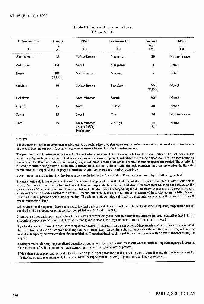
SP 15 (Part 2) :2000
Table 4 Effects of Extraneous Ions
(Clause 9.2.1)
Extraneous Ion Amount Effect Extraneous Ion Amount Effect
mg mg(1) (2) (3) (1) (2) (3)
Aluminimum 15 No interference Magnesium 20 No interference
Antimonic 150 Note 1 Manganous 15 Note 4
Borate 100 No intefereence Mercuric 5 Note I(H,BOJ
Calcium 50 No interference Phosphate 500 Note 5(H3B0,)
Cobaltous 1 No interference Starmic 500 Note 2
Cupric 35 Note 3 Thanic 40 Note 2
Ferric 25 Note 3 Zinc 80 No interference
Lead 15 No interference Zkonyl Note 2even in PbSO~ (:)Precipitates
NOTES
1 If antimony(it) and mercuryremain in solutionthey do not interfere,thoughmercurymay causelow resultswhen presentduringthe extractionof traces of iron and copper. It isusually necessaryto removethe metals bythe followingpWcess.
The perchloric acid is not expelled at the end of the wet rsshingprocedurebut the flask is cooled and the residue diluted. The solution is madeabout 3 N in hydrochloricacid, boiledto dissolveantimoniccompounds,ifpreserr~anddilutedto a total acidityof about lN. It is then heated ona water-bath for 30 minutes while a current of hydrogensrdphidesispassed through it. The flask is than stoppered and cooled. The solution isfiltered, the filtrate being returned to the flask and evaporated to small volume. Atler the neck extension has been replaced on the flask theperchloric acid isexpelled and the preparationof the solution completedas in Method 1(see 9.1 ).
2 Zirconium, tin and titanium interferebecausethey are hydrolyzedat low acidities. They maybe removed by the following method:
The perchloric acid is not expelled at the end of the wet-ashing procedurebut the flask is cooled and the residue diluted. Hydrochloric acid isadded, ifnecessary, to assist the solution of tin nodtitaniumcompounds,the solutionisboileduntil free from chlorine, cooled and diluted until itcontains about 10percent by volume of concentratedacids. It is transferredto a separating funnel. treated with excess of a 10percent aqueoussolution of cupferron,and extractedwith several 10ml portionsof methylenechloride. The completenessof the precipitationshould be checkedby adding more cupferron atter the first extraction. The white stannic complex is ditlicult to distinguish from excess of the reagent but it is lesstranslucent than the latter.
Atter extraction, the aqueousphase is returnedto the flaskandevaporatedto smallvolume. The neckextension is replaced, the perchloride acidexpelled, and the preparationof the solution completed as in Method 1(see 9.1).
3 Amounts of iron and coppergreaterthan 1or 2 mg arenot convenientlydealtwith by the oxinateextractionproceduredescribed in 9.3. Largeamounts of copper should be separatedby the method given inNote 1,and large amountsof ironby that given in Note 2.
If the total amount of ironand copper inthe samplesis koownnotto exceed 10pg the extractionofthese metals as their oxinatesmay be omitted,the neutralized and re-aciditied solution being oxidized immediately. Under these circumstances rdso,the solution from the dry ash maybetreatedwith diphenylcarbazidewithout furtheroxidation. The opticaldensitiesofthe solutionsshouldbe readwitldn a few minutesof addingthereagent.
4 Mangauesc dioxide maybe precipitatedwhenthe chromiumis oxidizedand causelow resultswhen morethan 1mg ofmangaoese is present.If the solution is free tiom ammonium salts as much as 15mg of manganesemay be present.
5 Phosphate causes precipitation of the feric ion and only 15mg of phosphoric acid can be tolerated or 5 mg if ammonium salts are absent. Bysubstituting potasium permanganatefor feric ammoniumsulphatethe full 500mg of phosphoricacidmay be tolerated.
----
/
234 PART 2, SECTION D/9
SP 15 (Part 2) :2000.—-
Iron and copper cause fading of the colour and variationin its hue; the procedure described in 9.3 thereforeprovides for the removal of small amounts of thesemetals.
9.3 Determination
9.3.1 Reagents
a)
b)
c)
d)
e)
0
@
8-hydroxyquinoline (oxine) – 1percent solutionin 2 N acetic acid.
Chloroform – Recover this by shaking it withsuccessive portions of concentrated sulphuricacid until the acid remains almost colorless.Shake the solvent with excess of calciumhydroxide filter and distil it. Add alcohol (1percent by volume) to the distillate.
A4ethylene chloride - Recover the methylenechloride, which is used for the extraction ofCupferron complexes by shaking it withsuccessive pofiions of a 10 percent solution ofsodium hydroxide until the alkali remainsalmost colorless, and then distilling thesolvent over solid sodium hydroxide.
Ceric ammonium sulphate – 0.05 N solutionin 2 N sulphuric acid.
Sodium azide – 5 percent solution in water.
Diphenylcarbazide – 0.25 percent solution in
equal volumes of acetone and water; thissolution must be prepared daily.
.4mmonium sulphate – free from iron andcopper. Treat a 20 percent (m/v) solution ofthe salt with an excess of oxine solution andadjust of pH 5 to 6 (wide range paper) withdilute ammonium hydroxide. Extract thesolution with successive portions of chloroformuntil the solvent remains colorless and thenfilter it to remove suspended solvent.
9.3.2 Procedure
Transfer the acid solution from the ashing process, oran aliquot containing not more than 75 pg ofchromium, to a separating funnel, 0.05 ml of a 0.1percent solution of methyl orange if required, and treatthe solution with 1 ml of oxine solution. Neutralize
carefully with ammonium hydroxide to the mid hue ofthe indicator, or until the colour of the indicator isobscured by black ferric oxinate. If the end point ofthe indicator is accidentally passed acidify the solutionagain and repeat the neutralization. Add 10 mlchloroform, shake the funnel vigorously and after thelayers have separated, adjust the aqueous layer ifnecessary to neutrality with ammonia. Again shakethe funnel vigorously for 30 seconds]), remove thechloroform layer and extract the aqueous layer twicemore with fresh 10 ml portions of chloroform. Returnthe aqueous layer to the conical flask (see Note 3 underTable 4). Acidify the solution with 5 ml of 2 Nsulphuric acid, boil to expel any residual chloroformand treat while still boiling with 1 ml of fericammonium sulphate solution, boil for a further 10minutes and cool. Remove any solid, includingmanganese dioxide, by filtration and treat the clearsolution with 0.2 ml of sodium azide solution2) Thesolution should now be colorless. If the purple colourof permanganate or the brown colour of colloidalmanganese dioxide is present warm the solution gentlyuntil the colour disappears.
Transfer the cooled solution to 50 ml graduated flask,
treat with 2 ml of diphenylcarbazide reagent and dilute
to volume. Treat the ‘blank’ solution, prepared as
described in 8.1, or an aliquot portion corresponding
to that used for the actual test exactly as described
above.
Shake the solutions vigorously to remove dissolved
gases, transfer them to the cells of a Spekker
absorptiometer and measure their optical densities with
the use of 11ford 605, yellow green filters. Maximum
absorption occurs at a wavelength of about 540 nm.
The colour is fairly stable but fades to the extent of
about 1 percent in 1 hour.
Use the difference between the optical densities of the
‘test’ and ‘blank’ solutions to obtain the chromium
content of the former directly from a calibration graphconstructed as follows:
Transfer different measured amounts of a standardsolution of potasium bichromate to separate 50 mlvolumetric flasks each containing 5 ml of 2 Nsulphuric acid and dilute to about 40 ml with water.If acid ashed samples are to be used add 5 gammonium sulphate, free from iron and copper. Add2 ml diphenylcarbazide reagent to each flask, thendilute the contents of each to 50 ml. Plot the optical
PART 2, SECTION D/9
/
235

-
SP 15 (Part 2) :2000
density of each solution, measured as above, against
its chromium content. Make fresh calibration graphs
for each batch of solid diphenylcarbazide and checkthe graphs periodically. Any other absorptiometermay be used, or the solutions may be comparedvisually with freshly prepared standards in uniformtubes, but these variations may affect the maximumpermissible amount of chromium in the sample.
10 ESTIMATION OF ZINC (Zn)
10.1 General
10.1.1 The dithizone method has been adopted forthis estimation. According to this method, the testsample is boiled in dilute hydrochloric acid for 30minutes in an Erlenmeyer flask, the contents cooled,
filtered and washed with water, the filtrate andwashings yielding a test solution. An aliquot of thissolution containing approximately 1 mg of zinc per100 ml of test solution is treated with acetate buffersolution (pH 4.75) and sodium thiosulphate solutionor with potassium cyanide solution and extractedwith dithizone to yield a bright red extract. Thisextract is compared against standard zinc solutiontreated exactly like the aliquot of the testthiosulphate.
10.1.2 In order to prevent interference due to ions ofcopper, mercury, lead and cadmium, the procedureprovides for the use of sodium thiosulphate solutionat pH 4.75. Next to these interfering metallic ions,cobalt and nickel are the other two important metals;when one or both of them are present the estimationhas to be repeated and the interference due to one orboth of them prevented by the use of potassiumcyanide solution in place of sodium thiosulphate.
10.3.2 Sodium Thiosulphate Solution
Prepared by dissolving sodium thiosulphate(Na,S,0,.5H20) in water to yield a 25 percent (m/v)solution.
10.3.3 Dilute Ammonia
Prepared by diluting ammonia (sp.gr 0.9) in water toyield at 1:1 (by volume) solution.
10.3.4 Potassium Cyanide Solution
Prepared by dissolving potassium cyanide in water toyield a 5 percent (w/v) solution.
10.3.5 DiIute Hydrochloric Acid— approximate 2 N.
10.3.6 Sodium Acetate Solution — approximate 2 N.
10.3.’? Dithizone Solution
Prepared by dissolving dithizone H~C,N=N–C(S) NHNHC,H, in carbon tetrachloride to yield a 0.001percent (m/v) solution (see 6.4.4).
10.3.8 Sodium Sulphate – solid, anhydrous.
10.3.9 Standard Zinc Solution
Prepared by dissolving zinc (30 mesh) in dilutehydrochloric acid (O.1 N) to yield a 0.01 percent (m/v)solution, taking 10 ml of the solution and diluting withwater to exactly 100 ml to yield ka 0.001 percent (m/v)solution. One millilitre of this solution contains 0.01mg of zinc (Zn).
10.2 Destruction of the Organic Matter10.4 Procedure
10.2.1 Follow the procedure as described in 6.1.1or 7.1.2.
10.3 Reagents
10.3.1 Acetate Bufler Solution ofpH 4.75
Prepared by mixing equal volumes of dilute sodiumacetate solution (2 N) and dilute acetic acid (2 N). Thesolution should be shaken well with 3 or 4 drops ofdithizone solution (see 10.3.7) to remove interferencedue to metallic ions, if any, and filtered through amoistened filter paper to remove drops of carbontetrachloride.
10.4.1 From the test solution prepared as in 10.2.1,choose an aliquot containing approximately 1 mg of zincper 100 ml of solution (making rough estimations ondifferent known quantities of the test solution, ifnecessary) transfer (see also 10.4.5) it to a 25 mlseparating funnel, add 5 ml of acetate buffer solutionand 1 ml of sodium thiosulphate solution (see Note);mix with 5 ml of dithizone solution and shake well for2 minutes. Allow the contents of the separating funnelto settle into two layers and when the lower of the twolayers thus formed is free from water droplets, dry thestem of the funnel with a piece of filter paper rolledround a thin glass rod and run the lower layer (extract)
.—.-!“
236 PART 2, SECTION D/9
I
Ii,
SP 15 (Part 2) :2000—.-.-..4
into a 25-ml volumetric flask avoiding exposure to directsunlight. Keep the flask well stoppered.
NOTE — When appreciableamountsof cobaltor nickelor botharepresent, add instead of acetate buffer and sodium thiosulphatesolutions, enough ammonia to neutralize and enough potassiumcyanide solution to dissolve the precipitate first formed; then adddilute hydrochloricacid dropby dropto bringthepH between3 and4 and adjust thepH to 5 to 5.5 with the addition of sodium acetatesolution. Use standardpH papers for adjustingpH.
10.4.2 Re-extract the portion left in the tinnel with 2or 3 ml of carbon tetrachloride and shake well for 2minutes. Allow the contents of the funnel to settle againinto two layers and when the lower of the two layersnow formed is free from water droplets, dry the stem ofthe funnel with a piece of filter paper rolled round a tinglass rod and run the lower layer into the 25 mlvolumetric flask containing the extract obtained asin 10.4.1.
10.4.3 Repeat the extraction two or three times (or untilthe aqueous layer in the separating fi,mnel is free fromred colour) collecting all the extracts in the samevolumetric flask.
10.4.4 Dilute the total extract with carbon tetrachlorideto exactly 25 ml; add 1 g of sodium sulphate and shakewell.
10.4.5 Prepare a series of reference standards takingdifferent known quantities of standard zinc solutioncontain approximately 1 mg or less of zinc per 100 mlof solution and treating the solutions side by side withand exactly as the aliquot of the test solution (see 10.4.1to 10.4.4).
10.4.6 Treat the ‘blank’ solution or an aliquot portioncorresponding to that used for the actual determinationexactly as described from 10.4.1 to 10.4.5.
10.4.7 Measure the optical densities of the extracts at/
.—suitable wavelength where the absorption of the
“1
—.
unchanged dithizone is at a minimum (510 rim). The
difference between the optical densities of the ‘test’and ‘blank’ extracts is used to obtain the zinc content
~
g’~’$~,:directly from a calibration graph constructed as given
,:
in 10.4.8. 2
10.4.8 Extract a series of solutions containing different
measured amounts of standard zinc solutions andmeasure the optical densities of the extracts. Substractfrom each value the optical density of the extract from a
similar solution containing no added zinc and plot thedifferences against the zinc contents of the original
solutions. These differences are substantiallyindependent of the concentration of the dithizonesolution with in the range 0.001 5 percent to 0.0025percent.
NOTES
1 The success of this method depends on scrupulous cleanliness.All apparatus shall be washed, first with dilute hydrochloric acidandthen with distilledwater immediatelybefore use.
2 The colour of the extract and those of extracts prepared similarlyfrom a series of aqueous solutions containing known amounts ofzinc may be comparedvisually in small stopperedtubes of uniformdimensions. The colours are stable for a few hours if the solutionsare protectedfrom light.
11 REPORT
The report shall include the following information:
a)
b)
c)
. .
Type and nature of textile being tested;
Amounts of copper, iron, manganese, ~i
chromium or zinc present; and
The type of treatment, if given to the fabric.
PART 2, SECTION D/9 237
SP 15 (Part 2) :2000
A-
ANNEX A
(Clauses 6.1.1,8.1.1 and9.1.1)
WET ASHING OF TEXTILE MATERIALS
A-1 INTRODUCTION
A-1. 1 Where destruction of organic matter in a sampleof textile material is required, and the ash is not to bedetermined, wet ashing possesses many advantages overdry ashing.
A-2 PRECAUTIONARY NOTE
A-2. 1 To avoid hazard, the conditions described mustbe carefully followed and any variation of extension ofthe method to materials other than those mentioned mustbe made only by fully trained operators.
A-3 PRINCIPLE
A-3.1 This method involves the controlled heating of
the sample with a suitable mixture of nitric, sulphuricand perchloric acids.
A-4 APPARATUS AND REAGENTS
A-4.1 Conical Flasks – with neck extensions (seeNote 1).
A-4.2 Hot Plate – with provision for maintaininggraded surface temperatures.
A-4.3 Safety Glass Screen – advisable until theoperator has had some experience of the method, andessential when working with previously untriedmaterials.
A-4.4 Boiling Rods
A-4.5 Nitric Acid – concentrated, relative density 1.42.
A-4.6 Sulphuric Acid – concentrated, relative density1.84.
A-4.7 Perchloric Acid – 60 percent, relative density1.54 (SW Note 2).
A-5 PROCEDURE
A-5.1 Place the specimen in the flask and add in theabove order the requisite quantities of the three acids.
238
After each addition, swirl the flask and allow anyreaction which takes place to proceed to completionbefore making a further addition. Fit a neck extensionto the flask, which is then placed on the cooler side ofthe hot plate, housed in an efficient fhme cup board.Vigorous evolution of brown fumes occurs, accompaniedby partial or complete solution of the sample. Cottondissolves only slowly, and most coating materials areresistant to oxidation at this stage.
A-5.2 When the evolution of brown fumes hasslackened, move the flask to the middle of the plateand allow excess of nitric acid and water to boil offgently. A gradually increasing evolution of gas,
culminating in a vigorous reaction and generation ofheavy white fumes, marks the action of the perchloric
acid and the virtual completion of the oxidation. Thereaction may be moderated, if necessary, by sliding theflask back to the cooler side of the hot plate. Charringof the reaction mixture at any stage should be rectifiedby swirling the tlask or by adding a few drops ofconcentrated nitric acid.
A-5.3 Finally, move the flask to the hottest part of theplate and allow the residual acid to reflux until the wallsof the flask and the lower portion of the neck have beenthoroughly washed by the distillate. During this process,lift the neck extension momentarily about three timesto release liquid held by capillary attraction at thejunction with the flask.
A-5.4 After the flask has been cooled, rinse the neckextension with about 20 ml of water and remove it. Thenboil the acids, thus diluted, for 2 minutes to expelchlorine, using a boiling rod to prevent pumping. Thediluted perchloric acid possess no oxidizing propertiesand the solution at this stage is ready for analysis.
A-5.5 Table 1 shows the amounts of each acidrecommended. The quantities given are suitable for usein 250 ml flasks unless otherwise stated. The additionof sulphuric acid produces a smoother reaction andfacilitates the clearance of any charring that may occur.When the nature of the subsequent analysis renders itspresence undesirablevolume of perchloricindic~ed.
it may be replaced by an equalacid, except in the few instances
PART 2, SECTION D/l O
SP 15 (Part 2) :2000
NOTES 2 The perchloric acid is pure enough for all but trace analysis, for
1 Conical flasks of 250 ml capacity are suitable for most purposes.which purpose it may be purified easily and economically by
The neck extensions are easily made by drawing down the closeddistillationas the 72 percent azeotropeunder reduced pressure.
ends of 200 mm x 25 mm boiling tubes, blowing out the ends, 3 The safety of the reaction depends upon the fact that readilychamfering them with a wire gauze and then flame polishing.Extensions for flasks of other sizes are made from tubes of
oxidizable matter destroyedby the nirtic acid before the perchloricacid reaches its reaction temperature of about 140”C. Addition of
proportionatedimensions. the acidsin the ordergivenreducesthe risk of accidentalommissionof the nirtic acid.
.—
. ----1,
PART 2, SECTION D/10 239
* f+
SP 15 (Part 2) :2000
DETERMINATION OF SCOURING LOSS IN GREYAND FINISHED COTTON TEXTILE MATERIALS
(Source: IS 1383: 1977)
In the cotton textile industry, yams and fabrics undergo treatments in the course of which extraneous matter ofvarious types is gathered by or added to the original material which is it not scoured or is partly scoured may alsocontain natural impurities, such as oils, fats, waxes and pectins. Estimation of the quantity of natural impuritiesand extraneous matter present in the material is therefore, considered necessary. It covers two methods namely,Mild Method - Suitable for fabrics like cotton gauge, bandage cloth and fabrics of loose construction; andSevere Method - Suitable for other type of fabrics.
1 SCOPE
1.1 It prescribes two methods for determining thescouring loss (loss in mass on scouring) of grey andfinished cotton textile materials.
1.2 The methods prescribed are generally applicable
to grey and finished cotton textile materials wherein
only starch or tamarind kernel powder or both, andwater-soluble or easily removable finishing agents,
such as oils, fats, and china clay have been used and
which would normally be removed during the scouringprocess.
2 PRINCIPLE
The test specimen is taken and its moisture content is
determined. Another test specimen is scoured, washedand its oven-dry mass is determined. The scouring lossis calculated on the basis of oven-dry mass of the test
specimen.
3 SAMPLING
Sample shall be selected so as to be representative ofthe lot. Sample drawn in accordance with the procedure
laid down in the specification of the material or as agreedto between the buyer and the seller shall be taken as
representative of the lot.
4 APPARATUS
4.1 Soxhlet Aparatus
4.2 Drying Oven – Capable of maintaining atemperature of 105 + 3°C.
4.3 Weighing Balance – Capable of weighing to an
accuracy of 0.001 g.
240
5 REAGENTS
5.1 Unless specified otherwise analytical reagent gradechemicals shall be employed in test and distilled watershall be used where the use of water is intended.
5.2 Desizing Enzyme – Diastase (or other suitableenzyme).
5.3 Sodium Chloride – Solid.
5.4 Caustic Soda Solution – 2 percent (rrr/v), containing1 percent turkey red oil Grade 2 (total fatty matter,percent by weight, Min 50 percent).
5.5 Acetic Acid Solution – 1 percent (v/v).
5.6 Chloroform
6 ESTIMATION OF MOISTURE
6.1 Draw from the sample (see 3) at least 2 testspecimens (see Note), each weighing approximately 3g. Take one test specimen and weigh it accurately in aclean, dry and tared weighing bottle. Place the weighingbottle containing the test specimen in the drying ovenand dry the specimen at 105 + 3°C to constant mass.Weigh the oven-d~ specimen accurately. Calculate thepercentage of moisture in the test specimen, by thefollowing formula:
(a -b) ~ looMoisture content, percent = _
awherea = original mass, in g of the test specimen; andb = oven-dry mass, in g of the test specimen.
NOTE — If the samples rmdertestis fabric, the specimens drawu
shall preferablybe square ia shape.
6.2 Similarly determine the moisture content in thesecond test specimen and take the average of the twovalues.
PART 2, SECTION D/l O
/
.—SP 15 (Part 2) :2000
*
7 PREPARATION OF TEST SPECIMENS
Draw from the sample at least two test specimens eachweighing about 5 g. If the sample under test is yarn, cuteach test specimen, separately into pieces about 15 cmlong, form into separate bundle and tie each bundleloosely round the middle. If the sample under test isfabric, trim each test specimen parallel to the directions
of warp and weft and pull out, to form a fringe, 5 threadsall round.
8 PROCEDURE
8.1 Method A (Severe Method)
8.1.1 Weigh accurately one test specimen drawn asin 7. Dip the specimen in a solution (weighing 20 timesthe mass of the specimen), containing, 5 g of diastaseand 10 g of sodium chloride per litre, at 50°C and at apH of 6.5 to 7.7 (see Notes 1 and 2). Allow the specimento remain in the solution for 1% hours. During thisperiod, take it out from the desizing bath and wring itby hand four times. At the end of the period, removethe specimen, wash it thoroughly (without wringing)four times in hot and cold water successively, using 50ml of water for each wash.
NOTES1 The temperature and pH given for the desizing solution are theoptimumfor bacterialdiastase. If anyothertypeof desizingenzymeis used, then the temperature and pH should be modified to thatrecommendedby the supplier. As many enzymaticdesizing agentsslowly deteriorate in storage, great care should be taken to see thatthe sample ofdesizing agent, at the time of test, is of satisfactorydesizingetliciency.2 If any doubt exists as to whether the size or finish has beencompletely removed, the treatment with the enzymatic desizingsolutionshouldbe repeated,the specimenbeingagainweighedtierdrying to constant mass at 105 + 3°C and the percentage loss inmass again calculated. If the percentage loss in mass has increasedby not more than 0.25, then it maybe considered that completedesizing has been affected and the secondfigure be acceptedasthefinal figure. If the percentage loss in mass has increased by morethan 0.25 then the desizing treatment should be repeated until thefigure for percentage loss in mass does not differ fromthe previousfigure by more than 0.2S.
8.1.2 Put the specimen in a 500 ml conical flaskcontaining caustic soda solution weighing 20 times themass of the specimen and boil for one hour. Addadequate quantity of water to make up for the loss duringboiling. At the end of the period remove the specimen,wash it thoroughly (without wringing) in hot water and
dip it for 5 minutes in acetic acid solution. Finally wash(without wringing) the specimen in cold water. Dry thespecimen in drying oven at 105 + 3°C to constant massand weigh it accurately.
8.2 Method B (Mild Method)
8.2.1 Weigh accurately one test specimen drawn asin 7. Extract the specimen for one hour with chloroformin a Soxhlet apparatus at the rate of 6 cycles per hour.AI1ow the chloroform to dry off in the air, and wash thespecimen by alternate immersion in hot running water
and wringing by hand 12 times in succession. Immersethe specimen in 0.5 percent aqueous solution of diastase(20 to 30 times the mass of the specimen) at 50°C andwring by hand repeating the process three times insuccession. Finally, return the specimen to the solutionand heat to 70°C. Allow the specimen to remain in thesolution for 15 minutes and then wash it well in hotrunning water. Squeeze and dry the specimen at105 + 3°C and weigh accurately.
9 CALCULATION
9.1 Calculate the percentage of scouring loss by thefollowing formula:
Scouring loss, percent [f’@@-4x100(oven-dry basis) = _____
where k-~)
M, = original mass i~ g of the specimen;
m = moisture content, percent (see 6.2); and
Mz = oven-dry mass in g of the specimen aftertreatment (see 8.1 or 8.2).
9.2 Repeat the test with the remaining test specimen(s)and find out the average of all the values.
10 REPORT
The report shall include the following information:
a) Type of material:
b) Method used (A or B);
c) Scouring loss, percent; and
d) Number of test specimens tested.
,,.,...-.
~i
t$
PART 2, SECTION D/10 24 I
II
!
A.-
SP 15 (Part 2) :2000
DETERMINATION OF SCOURING LOSS OFRAYON FILAMENT YARN
(hurce: IS 11219: 1984)
Continuous filament viscose rayon yam and acetate yam commonly used of weaving or knitting are generallytreated with special lubricants of sizes or gelatin during spinning. The general process of cleaning these filamentyams from the added lubricants of sizes is termed as scouring. The knowledge of loss due to scouring is very
essential to arrive at the commercial mass of the lot which is an important criteria for grading of these filamentyams.
Since the quality of lubricants of size used during spinning is not high, the method given in this standard prescribesa simple mild treatment.
1 SCOPE
It prescribes a method for determining the scouring loss
of viscose rayon and acetate rayon filament yams.
2 PRINCIPLE
A known amount of sample is scoured with mild sodium
carbonate solution. The loss in mass is determined and
expressed as a percentage of the dry mass of the sample.
3 SAMPLING
3.1 Lot
The quantity of yarn of the same grade and from the
same source delivered to a buyer against one despatch
note shall constitute a lot. If the lot contains more than
200 kg of yam, it shall be divided into sub-lots, each
weighing 200 kg or less.
3.1.1 Each sub-lot shall be tested separately.
3.2 Unless otherwise agreed to between the buyer and
the seller, 15 increments each approximately weighing10 g shall be taken from different parts of a sub-lot so
that a representative sample is obtained. All theincrements thus collected shall be thoroughly mixed.
This shall constitute the test sample.
4 PREPARATION OF TEST SPECIMENS
From the test sample, draw at least 2 specimens each
weighing about 5 g accurate to the nearest mg.
5 ATMOSPHERIC CONDITIONS FOR TESTING
The test shall be conducted in prevailing atmospheric
conditions.
NOTE — Shw the dry massesaredetermined,it isnot necessarytoconditionthe sample.
6 APPARATUS
6.1 Drying Oventemperature of 105 tq
6.2 Weighing Bottle
– Capable of maintaining a110”C.
– with a stopper.
6.3 Weighing Balance – Capable of weighing to anaccuracy up to 1 mg.
7 REAGENTS
7.1 Quality of Reagents
Unless specified otherwise, pure chemicals shall beemployed in tests and distilled water shall be used wherethe use of water as reagent is intended.
NOTE — ‘Purechemicals’shallmeanchemicalsthat do not containimpuritieswhich affectthe test results,
7.2 Sodium Carbonate Solution – (2 g/1),
8 PROCEDURE
8.1 Take a test specimen. Transfer it to a tared weighingbottle. Dry the specimen at 105° to 11O°C to constantmass (about 2 hours drying is sufficient) (see Note).Determine the oven-dry mass of the test specimen.
NOTE — For acetate rayon a drying temperature of 70-75~Cshallbe used andthe period of drying maybe prolonged to 4 hours till aconstant mass is obtained. If two consecutive readings taken at anintervalof30 minutes of drying do not differ by more than 2 mg, itshould be taken as constant mass.
8.2 Take the dried test specimen in a beaker containing250 ml of 2 g/1 sodium carbonate solution. Treat thetest specimen in this solution at 60-70”C for 30
—..-
242 PART 2, SECTION D/l 1
I1
-—SP 15 (Part 2) :2000
minutes. After this take out the test specimen, wash itthoroughly with hot water (below 70°C) and dry it inthe tared weighing bottle, as prescribed in 8.1, to aconstant mass. Determine the oven-d~ mass of thetreated test specimen.
NOTE — The material to liquor ratio should be 1:50
8.3 Calculate the percentage of scouring loss by thefollowing formula:
()w- fn2 x Iws= y–1
where
S = scouring loss, in percent, by mass on oven-drybasis;
PART 2, SECTION D/l 1
ml = oven-dry mass, in g, of the specimen beforescouring; and
mz = oven-dry mass, in g, of the specimen afierscouring.
8.4 Repeat the procedure given in 8.1 and 8.2 with theremaining test specimen(s) and calculate the percentage
of scouring loss by the formula given in 8.3.
8.5 Calculate the average of the values obtained as in8.3 and 8.4.
9 REPORT
The report shall include the following information:
a) Type and grade of material; and
b) Average scouring loss, percent.
243
\.
I
SP 15 (Part 2) :2000
DETERMINATION OF SCOURING LOSSIN SILK TEXTILE MATERIALS
(Source IS 1582:1968)
Raw silk contains, besides sericin, some traces of fat and mineral matter. Silk may be used in raw state, andafterwards either boiled off or not, according to the purpose for which it is intended. The silk gum and otherimpurities are generally removed from the silk textile materials by the process of boiling. Silk textiles are boiled offby passing them through heated soap liquor and hot water.
Method of test for determining the quantity of sericin and other extraneous matter present in the material is,therefore, considered necessary. The method of test prescribed in this standard shall be used as an aid in thedetermination of scouring loss of silk textile materials.
1 SCOPE
1.1 It prescribes a method for determining the scouringloss of silk textile materials.
1.1.1 The method prescribed in this standard isgenerally applicable to silk textiles wherein only sericinand other extraneous matter which would normally beremoved during the scouring or boiling process.
2 PRINCIPLE
A known amount of sample is scoured with mild soapand soda solution. The loss in weight is determined andexpressed as a percentage of the dry weight of the sample.
3 SAMPLING
3.1 Sampling for Yarn
3.1.1 Lot (Yarn)
The quantity of yarn from the same source shallconstitute the lot. If the lot contains more than 200 kgof yam, it shall be divided into sub-lots, each weighing200 kg or less.
3.1.2 Unless otherwise agreed to between the buyer andthe seller, 15 increments each approximately weighing10 g shall be taken from different parts of a sub-lot sothat a representative sample is obtained. All theincrements thus collected shall be thoroughly mixed.This shall constitute the test sample.
3.2 Sampling for Fabrics
3.2.1 ~Of (~abric)
The quantity of fabric manufactured essentially underuniform conditions shall constitute a lot.
244
3.2.2 Unless otherwise agreed to between the buyer andthe seller the number of pieces to be selected from a lotshall be as given below. The pieces thus selected shallconstitute the gross sample:
Lot Size Sample Sizeup to 100 3101 “ 300 4301 “ 500 5
501 and above 7
3.2.3 From each piece in the gross sample about 25 gof fabric shall be taken out from at least 2 different parts.The parts shall then be cut into fiu-ther smaller piecesand thoroughly mixed. The pieces thus collected shallconstitute the test sample.
4 PREPARATION OF TEST SPECIMENS
From the test sample, draw at least 2 test specimenseach weighing about 5 g.
5 ATMOSPHERIC CONDITIONS
The test shall be conducted in prevailing atmosphericconditions.
NOTE — Since the dry weights are determined, it is not necessay
to conditionthe sample.
6 APPARATUS
6.1 Air Oven – Capable of maintaining a temperatureof 105 to 1Io”c.
6.2 Weighing Bottle – With a stopper,
7 REAGENTS
7.1 Quality of Reagents – Unless specified otherwise,pure chemicals shall be employed in tests and distilled
PART 2, SECTION D/12
——-,.-,
‘\,,f,
SP 15 (Part 2) :2000
water shall be used where the use of water as reagent isintended.
NOTE — ‘Purechemicals’shallmeanchemicalsthatdonot containimpuritieswhich afiect the test results.
7.2 Sodium Carbonate Solution – 1 percent (w/v).
7.3 Soap Solution – 1 percent solution (w/v) of neutralsoap.
NOTE— Oliveoil soapissuitableforthistest.
8 PROCEDURE
8.1 Take atest specimen. Transfer ittoataredweighingbottle. Dry the specimen at 105 to 110°C to constantweight (about 2 hours drying is sufficient) (see Note).Determine the oven-dry weight of the test specimen.
NOTE — The consecutiveweightstakenat an intervalof 30 minutesof drying should not differ by morethan2 mg.
8.2 Take the dried test specimen in a beaker. Boil itgently (see Note 1) for 1 hour with 150 ml of soapsolution (see Note 2). Squeeze the test specimen andtransfer it to a beaker containing 150 ml of sodiumcarbonate solution and boil for half an hour (see Notes1 and 2). Take out the test specimen, wash it thoroughlywith hot water and dry it in the tared weighing bottle toconstant weight (about 2 hours drying is sufficient) inthe oven. Determine the oven-dry weight of the testspecimen.
NOTES
1 For very fine quality of silk, the temperature of the soap or soda .:
solutionshouldbe 80°C.
2 The lmaterialto liquor ratio should be 1:30.
$-. .-.--!
8.3 Calculate the percentage of scouring loss by the,:)
following formula:
(w, - w,) x 100~.
w,
where
S = scouring loss, in percent, by weight on oven-dry basis;
WI = oven-dry weight, in g, of the specimen beforescouring; and
Wz = oven-dry weight, in g, of the specimen afterscouring.
8.4 Repeat the procedure given in 8.1 and 8.2 with theremaining test specimen(s) and calculate the percentageof scouring loss by the formula given as in 8.3.
8.5 Calculate the average of the values obtainedas in 8.3 and 8.4.
9 REPORT
Report the value obtained as inin percent, of the test sample.
8.5 as the scouring loss
PART 2, SECTION D/12 245
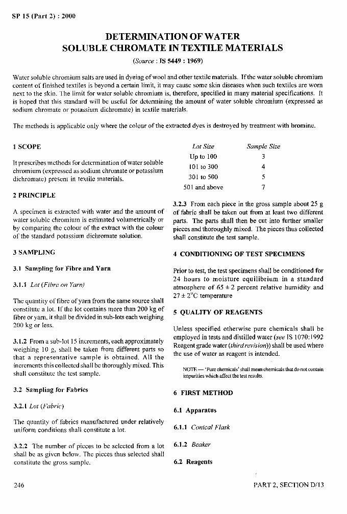
SP 15 (Part 2) :2000
DETERMINATION OF WATER
SOLUBLE CHROMATE IN TEXTILE MATERIALS
(Source : IS 5449: 1969)
Water soluble chromium salts are used in dyeing of wool and other textile materials. If the water soluble chromiumcontent of finished textiles is beyond a certain limit, it may cause some skin diseases when such textiles are wornnext to the skin. The limit for water soluble chromium is, therefore, specified in many material specifications. Itis hoped that this standard will be usetid for determining the amount of water soluble chromium (expressed assodium chromate or potassium bichromate) in textile materials.
The methods is applicable only where the colour of the extracted dyes is destroyed by treatment with bromine.
1 SCOPE
It prescribes methods for determination of water solublechromium (expressed as sodium chromate or potassiumbichromate) present in textile materials.
2 PRINCIPLE
A specimen is extracted with water and the amount ofwater soluble chromium is estimated volumetrically or
by comparing the colour of the extract with the colourof the standard potassium bichromate solution.
3 SAMPLING
3.1 Sampling for Fibre and Yarn
3.1.1 Lot (Fihre on Yarn)
The quantity of fibre of yarn from the same source shallconstitute a lot. If the lot contains more than 200 kg offibre or yam, it shall be divided in sub-lots each weighing200 kg or less.
3.1.2 From a sub-lot 15 increments, each approximatelyweighing 10 g, shall be taken from different parts sothat a representative sample is obtained. All theincrements this collected shall be thoroughly mixed. Thisshall constitute the test sample.
3.2 Sampling for Fabrics
3.2.1 Lot (Fabric)
The quantity of fabrics manufactured under relativelyuniform conditions shall constitute a lot.
3.2.2 The number of pieces to be selected from a lotshall be as given below. The pieces thus selected shallconstitute the gross sample.
246
Lot Size Sample Size
up to 100 3
lolto 300 4
301 to 500 5
501 and above 7
3.2.3 From each piece in the gross sample about 25 g
of fabric shall be taken out from at least two different
parts. The parts shall then be cut into further smallerpieces and thoroughly mixed. The pieces thus collected
shall constitute the test sample.
4 CONDITIONING OF TEST SPECIMENS
Prior to test, the test specimens shall be conditioned for
24 hours to moisture equilibrium in a standard
atmosphere of 65 + 2 percent relative humidity and
27+ 2°C temperature
5 QUALITY OF REAGENTS
Unless specified otherwise pure chemicals shall be
employed in tests and distilled water (see IS 1070:1992Reagent grade water (thirdrevision)) shall be used where
the use of water as reagent is intended.
6
NOTE — ‘Purechemicals’shallmeanchemicalsthat do not containimpuritieswhich affectthe test results.
FIRST METHOD
6.1 Apparatus
6.1.1 Conical Flask
6.1.2 Beaker
6.2 Reagents
/
P.4RT 2, SECTION D/l 3
.. ---
/
II
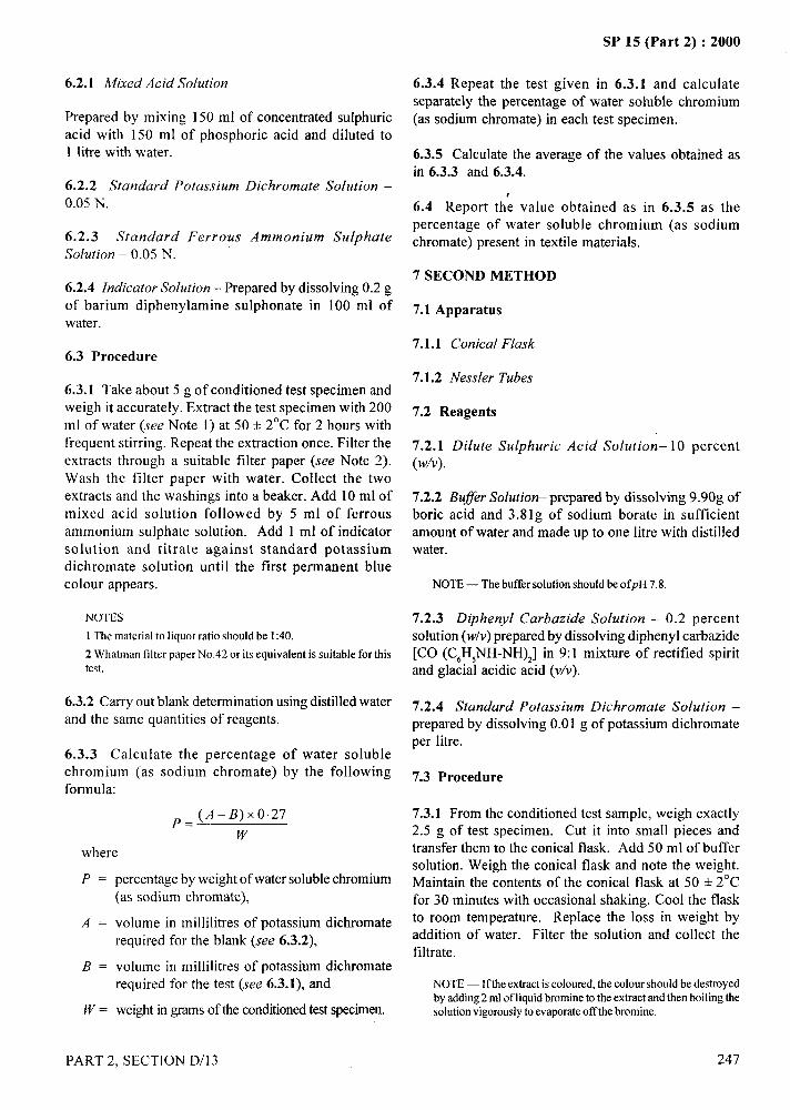
,#
6.2.1 Mixed Acid Solution
Prepared by mixing 150 ml of concentrated sulphuric
acid with 150 ml of phosphoric acid and diluted to
1 litre with water.
6.2.2 Standard Potassium Bichromate Solution –
0.05 N.
6.2.3 Standard Ferrous Ammonium Sulphate
Solution – 0.05 N.
6.2.4 Indicator Solution – Prepared by dissolving 0.2 gof barium diphenylamine sulphonate in 100 ml ofwater.
6.3 Procedure
6.3.1 Take about 5 g of conditioned test specimen andweigh it accurately. Extract the test specimen with 200ml of water (see Note 1) at 50 + 2°C for 2 hours withfrequent stirring. Repeat the extraction once. Filter theextracts through a suitable filter paper (see Note 2).Wash the filter paper with water. Collect the twoextracts and the washings into a beaker. Add 10 ml ofmixed acid solution followed by 5 ml of ferrousammonium sulphate solution. Add 1 ml of indicatorsolution and titrate against standard potassiumbichromate solution until the first permanent bluecolour appears.
NOTES
1 The material to liquor ratio should be 1:40.
2 Whatman filter paper No.42 or its equivalent is suitable for thistest.
6.3.2 Carry out blank determination using distilled waterand the same quantities of reagents.
6.3.3 Calculate the percentage of water solublechromium (as sodium chromate) by the followingformula:
~=(A-B) x027
w
where
p.
A=
B=
J’J7.
percentage by weight of water soluble chromium(as sodium chromate),
volume in millilitres of potassium bichromaterequired for the blank (see 6.3.2),
volume in millilitres of potassium bichromaterequired for the test (see 6.3.1), and
weight in gmms of the conditioned test specimen.
PART 2, SECTION D/13
SP 15 (Part 2) :2000
6.3.4 Repeat the test given in 6.3.1 and calculateseparately the percentage of water soluble chromium(as sodium chromate) in each test specimen.
6.3.5 Calculate the average of the values obtained asin 6.3.3 and 6.3.4.
6.4 Report th~ value obtained as in 6.3.5 as thepercentage of water soluble chromium (as sodiumchromate) present in textile materials.
7 SECOND METHOD
7.1 Apparatus
7.1.1 Conical FIask
7.1.2 Nessler Tubes
7.2 Reagents
7.2.1 Dilute Sulphuric Acid Solution– 10 percent(w/v).
7.2.2 Bu#er Solution- prepared by dissolving 9.90g ofboric acid and 3.81 g of sodium borate in sufficientamount of water and made up to one litre with distilledwater.
NOTE — The buffer solution should be ofpH 7.8.
7.2.3 Diphenyl Carbazide Solution – 0.2 percentsolution (w/v) prepared by dissolving diphenyl carbazide[CO (C,H,NH-NH),] in 9:1 mixture of rectified spiritand glacial acidic acid (v/v).
7.2.4 Standard Potassium Bichromate Solution –prepared by dissolving 0.01 g of potassium bichromateper Iitre.
7.3 Procedure
7.3.1 From the conditioned test sample, weigh exactly2.5 g of test specimen. Cut it into small pieces andtransfer them to the conical flask. Add 50 ml of buffersolution. Weigh the conical flask and note the weight.Maintain the contents of the conical flask at 50 + 2°Cfor 30 minutes with occasional shaking. Cool the flaskto room temperature. Replace the loss in weight byaddition of water. Filter the solution and collect thefiltrate.
NOTE — Ifthe extract is colourcd, the colour should be destroyedby adding2 ml ofliquid bromine to the extract and then boiling thesolutionvigorouslyto evaporateoff the bromine.
247
.—
SP 15 (Part 2) :2000
7.3.2 Take 20 ml of filtrate in a Nessler tube. Add to it5 ml of dilute sulphuric acid and 2 ml diphenyl carbazidesolution and make up the volume to 100 ml. Keep thecontents in the flask for 10 minutes. Compare the colourdeveloped with that of the solutions in which knownquantities of potassium bichromate solution are takenseparately instead of 20 ml of filtrate and treatedsimilarly.
NOTE — A violetpinkcolourisdevelopedwithdiphenylcarbazide.
7.3.3 Calculate the percentage of water soluble
chromium (as potassium bichromate) by the followingformula:
P=o.ool x v
where
P = percentage by weight of water solublechromium (as potassium bichromate), and
v = volume in millilitres of standard potassium
bichromate solution required to producecolour equal to colour of the extract.
7.3.4 Repeat the test with the remaining test specimens
and calculate the percentage of the soluble chromiumin each test specimen.
7.3.5 Calculate the average of the values obtained asin 7.3.3 and 7.3.4.
8 REPORT
The report shall include the following information:
a)
b)
c)
d)
Type of material tested;
Method followed;
Chromium, percent (as sodium chromate); or
Chromium, percent (as potassium bichromate).
(
—---
.;
#’-
248 PART 2, SECTION D/l 3
/
I I
I
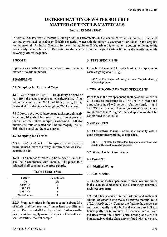
SP 15 (Part 2) :2000
DETERMINATION OF WATER SOLUBLEMATTER OF TEXTILE MATERIALS
(Source : IS 3456: 1966)
In textile industry textile materials undergo various treatments, in the course of which extraneous matter ofvarious types, such as sizing or finishing material, water soluble matter is gathered by or added to the originaltextile material. An Indian Standard for determining size or finish, ash and fatty matter in cotton textile materialshas already been published. The water soluble matter if present beyond certain limits in the textile materialsadversely affects its quality.
1 SCOPE
It prescribes a method for determination of water solublematter of textile materials.
2 SAMPLING
2.1 Sampling for Fibre and Yarn
2.1.1 Lot (Fibre or Yarn) – The quantity of fibre or
yam from the same source shall constitute a lot. If thelot contains more than 200 kg of tibre or yam, it shall
be divided in sub-lots each weighing 200 kg or less.
2.1.2 From a sub-lot 15 increments each approximatelyweighing 10 g shall be taken from different parts sothat a representative sample is obtained. All theincrements thus collected shall be thoroughly mixed.This shall constitute the test sample.
2.2 Sampling for Fabrics
2.2.1 Lot (Fabric) – The quantity of fabrics
manufactured under relatively uniform conditions shallconstitute a lot.
2.2.2 The number of pieces to be selected from a lot
shall be in accordance with Table 1. The pieces thusselected shall constitute the gross sample.
Table 1 Sample Size
Lot Size Sample Size
(1) (2)UP to 100 3101 “300 4301 “ 500 5
501 and above 7
2.2.3 From each piece in the gross sample about 25 gof fabric shall be taken out from at least two differentparts. The parts shall then be cut into further smaller
pieces and thoroughly mixed. The pieces thus collected
shall constitute the test sample.
PART 2, SECTION D/14
3 TEST SPECIMENS
From the test sample, take out at least two test specimenseach weighing about 10 g.
NOTE — Ifthe sampleunder analysis is loose tibre, take about 5 gof the test specimen.
4 CONDITION1NG OF TEST SPECIMENS
Prior to test, the test specimens shall be condhioned for24 hours to moisture equilibrium in a standardatmosphere at 65 + 2 percent relative humidity a,ld27+ 2°C temperature. However, in case of fabrics which
weigh more than 270 g/mz, the test specimens shall beconditioned for 48 hours.
5 APPARATUS
5.1 Flat-Bottom Flasks – of suitable capacity with aglass stopper incorporating a stop-cock.
NOTE — The flasksthat are used for the preparation of the extractshould not be used for any other purpose.
5.2 Water Cooled Condensers
6 REAGENT
6.1 Distilled Water
7 PROCEDURE
7.1 Condition the test specimens to moisture equilibriumin the standard atmosphere (see 4) and weigh acurately
each test specimen.
7.2 Put a test specimen in the flask and add sufficientamount of water to it to make a liquor to material ratioof 20:1 (see Note 1). Connect the flask to the condenserand bring rapidly to the boil and continue to boil theliquor gently for 60 minutes. Disconnect and removethe flask while the liquor is still boiling and close itimmediately with the glass stopper fitted with stop-cock.
249
/
SP 15 (Part 2) :2000
...-
Rapidly cool the flask to room temperature (27+ 2“C).Do not remove or open the tap until ready for filtration.Reject any extract where the flask is not under vacuumat the time of opening. Filter the extract and wash theresidue with small amount of water. Take the filtrateand washings in a tared vessel and evaporate the extractto dryness (see Note 2). Dry the residue to constantweight at 105 to 110”C.
NOTES
1 If the test specimen iswool, the liquor to material ratio should be50:1.
2 The filtrate and washingsmaybe dilutedto a suitablevolumeanda measuredamountof the solutionmaybe evaporatedforestimation.
8 CALCULATIONS
8.1 Calculate the water soluble matter as a percentageof the conditioned weight of the specimen by thefollowing formula:
where
P = percentage of water soluble matter;
W2 = weight, in g, of the residue (see 7.2); and
W, = Weight, in g, of the conditioned test specimen(see 7.1).
8.2 Repeat the test as given in 7.2 with the remainingtest specimen(s) and calculate the percentage of watersoluble matter in each test specimen.
8.3 Calculate the average of the values obtained asin 8.1 and 8.2 and report it as the percentage of watersoluble matter of the textiles.
9 REPORT
Calculate the average of the values obtained as in8.1 and 8.2, and report it as the percentage of watersoluble matter of the textiles.
250
/
PART 2, SECTION D/l 4
Ii,lI
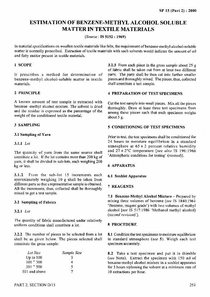
SP 15 (Part 2) :2000
ESTIMATION OF BENZENE-METHYL ALCOHOL SOLUBLEMATTER IN TEXTILE MATERIALS
(Source: IS 5152: 1969)
In material specifications on woollen textile materials like felts, the requirement of benzene-methyl alcohol-solublematter is normally prescribed. Extraction of textile materials with such solvents would indicate the amount of oiland fatty matter present in textile materials.
1 SCOPE
It prescribes a method for determination ofbenzene-methyl alcohol-soluble matter in textilematerials.
2 PRINCIPLE
A known amount of test sample is extracted withbenzene -methyl alcohol mixture. The solvent is driedand the residue is expressed as the percentage of theweight of the conditioned textile material.
3 SAMPLING
3.1 Sampling of Yarn
3.1.1 Lot
The quantity of yarn from the same source shallconstitute a lot. If the lot contains more than 200 kg ofyarn, it shall be divided in sub-lots, each weighing 200kg or less.
3.1.2 From the sub-lot 15 increments eachapproximately weighing 10 g shall be taken fromdifferent parts so that a representative sample is obtained.All the increments, thus, collected shall be thoroughlymixed to get a test sample.
3.2 Sampling of Fabrics
3.2.1 Lot
The quantity of fabric manufactured under relativelyuniform conditions shall constitute a lot.
3.2.2 The number of pieces to be selected fi-om a lotshall be as given beIow. The pieces selected shallconstitute the gross sample:
Lot Size Sample Size
up to 100 3101 “ 300 4
301 “ 500 5
501 and above 7
PART 2, SECTION D/l 5
3.2.3 From each piece in the gross sample about 25 gof fabric shall be taken out from at least two differentparts. The parts shall be then cut into further smallerpieces and thoroughly mixed. The pieces, thus, collectedshall constitute a test sample.
4 PREPARATION OF TEST SPECIMENS
Cut the test sample into small pieces. Mix all the piecesthoroughly. Draw at least three test specimens fromamong these pieces such that each specimen weighsabout 5 g.
5 CONDITIONING OF TEST SPECIMENS
Prior to test, the test specimens shall be conditioned for24 hours to moisture equilibrium in a standardatmosphere at 65 + 2 percent relative humidityand 27 k 2°C temperature [see also IS 196:1966‘Atmospheric conditions for testing’ (revised].
6 APPARATUS
6.1 Soxhlet Apparatus
7 REAGENTS
7.1 Benzene-Methyl Alcohol Mixture – Prepared bymixing three volumes of benzene (see IS 1840:1961‘Benzene, reagent grade’) with two volumes of methylalcohol [see IS 517:1986 ‘Methanol methyl alcohol)(second revision)’].
8 PROCEDURE
8.1 Condition the test specimens to moisture equilibriumin standard atmosphere (see 5). Weigh each testspecimen accurately.
8.2 Take a test specimen and put it in thimble(see Note). Extract the specimen with 150 ml ofbenzene-methyl alcohol mixture in a soxhlet apparatusfor 3 hours siphoning the solvent at a minimum rate of10 extractions per hour.
251
,,, d.—.
—.
!
SP 15 (Part 2) :2000
NOTE — If the thimble is not available, the test specimen shoold b=be wrapped in filter paper. a=
8.3 Evaporate the extract in a tared flask. Dry theresidue to constant weight at 105 to 110”C and weigh.
8.5 Rep
weight, in g, of the residue (see 8.3); and
conditioned weight, in g, of the test specimen(see 8.1).
~eat the test with the remaining test specimens
8.4 Calculationsand calculate the benzene-methyl alcohol-soluble matterin each test specimen.
8.4.1 Calculate the percentage of benzene-methylalcohol-soluble matter present in the textiles by the
8.6 Calculate the average of the values obtained as
following formula:in 8.4.1 and 8.5.
p=~xlooa
where
p = percent, by weight, benzene-methylsoluble matter in the test specimens;
252
9 REPORT
Report the value obtained as in 8.6 as the benzene-
alcohol- methyl alcohol-soluble matter present in the testsample.
PART 2, SECTION D/l 5
/
I~!I I
SP 15 (Part 2) :2000
METHOD FOR DETERMINATION OFETHER SOLUBLE MATTER IN TEXTILE MATERIALS
(Source: IS 4390: 1967)
In the cotton textile industry, yarn or fabric undergoes treatments in the course of which extraneous matter ofvarious types is gathered by or added to the original material. The ether-soluble matter, if present beyond certainlimits in the textile goods used as insulating materials in electrical industry, affects the quality of the insulatingmaterials.
1 SCOPE
It prescribes a method for determination of ether-solublematter in textile materials.
2 SAMPLING
2.1 Sampling for Fibre and Yarn
2.1.1 Lot (Fibre or Yarn)
The quantity of fibre or yarn from the same source shallconstitute a lot. If the lot contains more than 200 kg offibre of yarn, it shall be divided in sub-lots each weighing200 kg or less.
2.1.2 From a sub-lot, 15 increments each approximatelyweighing 10 g shall be taken from different parts sothat a representative sample is obtained. All theincrements thus collected shall be thoroughly mixed.This shall constitute the test sample.
2.2 Sampling for Fabrics
2.2.1 Lot (Fabric)
The quantity of fabrics manufactured essentially under
uniform conditions shall constitute a lot.
2.2.2 The number of pieces to be selected from a lotshall be as given below. The pieces thus selected shallconstitute the gross sample.
Lot Size Sample Size
up to 100 3
101 “ 300 4
301 “ 500 5
501 and above 7
2.2.3 From each piece in the gross sample above 25 gof fabric shall be takex out from at least two different
PART 2, SECTION D/l 6
parts. The parts shall then be cut into further smallerpieces and thoroughly mixed. The pieces thus collectedshall constitute the test sample.
3 TEST SPECIMENS
From the test sample, cut at least two test specimenseach weighing about 10 g. Cut the test specimens intosmall pieces.
4 CONDITIONING OF TEST SPECIMENS
Prior to test, the test specimens shall be conditioned for24 hours for moisture equilibrium in standardatmosphere at 65 + 2 percent relative humidity and27+ 2°C temperature.
5 APPARATUS
5.1 Soxhlet Apparatus
5.2 Reflux Condenser
6 REAGENTS
6.1 Quality of Reagents – Unless specified otherwise,pure chemicals shall be employed for tests and distilledwater shall be used where the use of water or distilledwater as reagent is intended.
NOTE— ‘purechemicals’shallmeanchemicalsthatdonotcontainimpuritieswhichaffectthetestresults.
6.2 Ethyl Ether – redistilled.
7 PROCEDURE
7.1 Take one test specimen conditioned as in 4.1 andweigh it accurately. Place it in a thimble of Soxhletapparatus. Extract the test specimen with ethyl etherfor 3 hours at a minimum rate of 6 c/h.
7.2 Reduce the extract, if necessary, by subsequent
distillation to a volume of approximately 25 ml. Filter
253
SP 15 (Part 2) :2000
the extract through a rapid filter paper and collect the
extract in a 50-ml tared flask. Wash the filter paper andthe extraction flask with small portions of ether andadd the washings to the extract.
7.3 Distill the extract to remove the solvent by heatingthe flask on a steam-bath. Dry the residue at 60 to 70”Cto constant weight.
8 CALCULATION
8.1 Calculate the amount of ether-soluble matter by thefollowing formula:
awhere
S = percentage, by weight, of ether-soluble matter;
- ..—
W1= Weight, in grams, of the residue (ether-soluble —-4matter) (see 7.3); and
-7$.!
Wz = Weight, in grams, of the conditioned test
specimen (see 7.1).
1
~,...,.-‘;,
.:
8.2 Repeat the test with the remaining test specimen(s)-j
and calculate the percentage of ether-soluble matter in
each test specimen.
8.3 Calculate the average of the values obtained as
in 8.1 and 8.2.
9 REPORT
9.1 Report the value obtained as
soluble matter in textile materials.
in 8.3 as the ether-
)’
254 PART 2, SECTION D/16
I:!I
I
SP 15 (Part 2) :2000
DETERMINATION OF IRON AND
CHROMIUM IN TEXTILES(Source: IS 4655: 1968)
Iron and chromium are present in large quantities in textiles, dyed in mineral khaki. Mineral khaki dyed material isused by Defence Personnel and civilians as well for making uniforms. The iron and chromium content of the fabricwould give an indication regarding the amount of mineral khaki present in the textile material. This standard wouldbe useful for the purpose of determining iron and chromium present in the textile material.
1 SCOPE
It prescribes method for determination of iron andchromium present in textile materials, especially dyed inmineral khaki and olive green shades.
2 PRINCIPLE
A known amount of test sample is ashed and the amountof iron and chromium is determined as their oxides(Fe,O, and Cr20,) and expressed as the percentage ofthe conditioned weight of the test sample.
3 SAMPLING
3.1 Sampling for Yarn
3.1.1 Lot (Yarn)
The quantity of yam from the same source shall constitute
the lot. If the lot contains more than 200 kg of yarn, itshall be divided into sub-lots, each weighing 200 kg orless.
3.1.2 Test Sample
Unless otherwise agreed to between the buyer and theseller, 15 increments each approximately weighing 10 gshall be taken from different parts of each sub-lot so thata representative test sample is obtained. All theincrements thus collected shall be thoroughly mixed.
3.2 Sampling for Fabrics
3.2.1 Lot (Fabric)
The quantity of fabrics manufactured essentially underuniform conditions shall constitute a lot.
3.2.2 Gross ,Yumple
Unless otherwise agreed to between the buyer and theseller, the number of pieces to be selected from a lot to
PART 2, SECTION D/17
constitute gross sample shall be as given below.”
Lot Size Sample Size
up to 100 3
101 “ 300 4
301 “ 500 5
501 and above 7
3.2.3 Test Sample
From each piece in the gross sample about 25 g of fabric
shall be taken out from at least two different parts toconstitute test sample. The parts shall then be cut into
further smaller pieces and thoroughly mixed.
4 PREPARATION OF TEST SPECIMEN
Cut the test sample into small pieces. Mix all the piecesthoroughly. Draw at least 3 test specimens from amongthese pieces such that each specimen weighs 5 g.
5 CONDITIONING OF TEST SPECIMEN
Prior to test, the test specimen shall be conditioned for
24 hours to moisture equilibrium in a standardatmosphere at 65 + 2 percent RH and 27 + 2°Ctemperature.
6 APPARATUS
6.1 Porcelain Crucible
6.2 Beakers
7 REAGENTS
7.1 Quality of Reagents
Unless specified otherwise, pure chemicals shall be
employed in tests and distilled water shall be used wherethe use of water or distilled water as reagent is intended.
255
..
f.:..
SP 15 (Part 2) :2000
NOTE — ‘Parechemicals’shall mean chemicalsthat do not contain ash it in a muffle furnace at 800°C for 15 minutes andimpuritieswhich affect the test results. fuse the ash over a bunsen flame to clear melt with 10 g
7.2 Hydrogen Peroxideof potassium bisulphate. Dissolve the melt in 100 ml ofhot water and add 100 ml of hydrogen peroxide. Add
6 percent (w/w) (or 20 volumes).enough amount of sodium hydroxide solution till the
solution is slightly alkaline. Boil the solution gently for
7.3 Sodium Hydroxide Solution – 20 percent (w/v).5 minutes and filter it through Whatman No. 54 or itsequivalent filter paper. Wash the precipitate with hot
7.4 Dilute Hydrochloric Acid – equal volumes ofwater. Collect the filtrate and the washings.
concentrated hydrochloric acids and water, NOTE— Ifthe amountof iron and chromium compounds whichhave been fixed properly on the fabric is to be determined the
7.5 Dilute Sulphuric Acid – 10 percent (w/v). water-solublecompoundsof iron and chromium ( which havenot been properly fixed) should be removed by the following
7.6 Mixed Acid Solution – prepared by mixing 150 ml procedure:
of concentrated sulphuric acid and 150 ml of phosphoric ‘Beforeashing, put the test specimen in a 250 ml beaker. Add100 ml of distilled water and boil it for 15 minutes. Wash the
acid and made up to 1 litre with water. test specimen thoroughly, first with warm water and then withcold water. Dry the test specimen and follow the procedure given
7.7 Ferrous Ammonium Sulphate Solution – N/IO. in 8.2’.
7.8 Potassium Bichromate Solution – (a) N/10, and 8.3 Dissolve the precipitate obtained as in 8.2 in 10 ml
(b) N/20. of hot dilute hydrochloric acid. Wash the filter paperthoroughly with distilled water till the washings are fi-ee
7.9 Stannous Chloride Solution – 5 percent (w/v). from iron. Add 5 ml of hydrogen peroxide solution andreprecipitate iron with sodium hydroxide solution as
7.10 Mercuric Chloride Solution – saturated. in 8.2. Boil it for 5 minutes. Filter off the precipitateand wash it till free from chromium.
7.11 Indicator Solution – prepared by dissolving 0.2 gof barium diphenylamine sulphonate in 100 ml of water. 8.4 Combine the filtrate as obtained in 8.2 and 8.3.
7.12 Potassium Permanganate Solution –(a) saturated,and (b) N/20.
7.13 Potassium Bisulphate – anhydrous.
7.14 Potassium Iodide – crystals.
7.15 Starch Indicator – 1 percent solution.
7.16 Sodium Thiosttlphate Solution – N/20.
7.17 Reinhardt Solution – prepared by dissolving 200g of manganese sulphate in 1000 ml of water to which isadded a cooled mixture of 400 ml of concentratedsulphuric acid, 1200 ml of water and 400 ml of syrupyphosphoric acid.
8 PROCEDURE
8.5 Determination of Chromium
8.5.1 First Method
8.5.1.1 Concentrate the filtrate obtained as in 8.4 andneutralize it with dilute sulphuric acid. Add 10 ml ofdilute sulphuric acid in excess. Add 25 ml of N/l Oferrousammonium sulphate solution followed by 20 ml of mixedacid solution and 1 ml of indicator solution. Titrate themixture against N/10 potassium bichromate solution tothe first permanent blue colour.
8.5.1.2 Carry out a blank test by following the proceduregiven in 8.5.1.1 using distilled water instead of the filtrateobtained as in 8.4.
8.5.1.3 Calculate the percentage of chromium aschromium oxide (Crz OJ by the following formula:
8.1 Condition the test specimens to moisture equilibrium ~=(V,-V,)XO.2534in standard atmosphere (see 5) and weigh each test wspecimen accurately. where
8.2 Put a test specimen in porcelain crucible (see Note), A = percent by weight of chromium as Cr,OJ,
i,,*J.,
256 PART 2, SECTION D/17
/
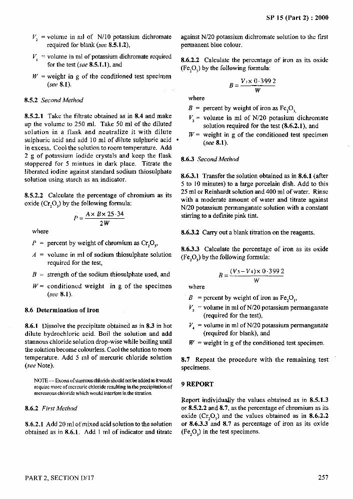
Vz = volume in ml of N/10 potassium bichromate
required for blank (see 8.5.1.2),
V, = volume in ml of potassium bichromate required
for the test (see 8.5.1.1), and
W = weight in g of the conditioned test specimen(see 8.1).
8.5.2 Second Method
8.5.2.1 Take the filtrate obtained as in 8.4 and makeup the volume to 250 ml. Take 50 ml of the dilutedsolution in a flask and neutralize it with dilutesulphuric acid and add 10 ml of dilute sulphuric acidin excess. Cool the solution to room temperature. Add2 g of potassium iodide crystals and keep the flaskstoppered for 5 mintues in dark place. Titrate theliberated iodine against standard sodium thiosulphatesolution using starch as an indicator.
8.5.2.2 Calculate the percentage of chromium as its
oxide (Cr20q) by the following formula
;= Ax Bx25.34
2Wwhere
P = percent by weight of chromium as CrzOj,
A = volume in ml of sodium thiosulphate solutionrequired for the test,
B = strength of the sodium thiosulphate used, and
W = conditioned weight in g of the specimen(see 8.1).
8.6 Determination of Iron
8.6.1 Dissolve the precipitate obtained as in 8.3 in hotdilute hydrochloric acid. Boil the solution and addstannous chloride solution drop-wise while boiling untilthe solution become colorless. Cool the solution to roomtemperature, Add 5 ml of mercuric chloride solution
i(see Note).
I NOTE — Excessof stannouschlorideshoutdnotbe addedas itwouldrequire more of mercuric chloride resulting in the precipitation ofmercurouschloride which would interfereinthe titration.
8.6.2 First Method
8.6.2.1 Add 20 ml of mixed acid solution to the solutionobtained as in 8.6.1. Add 1 ml of indicator and titrate
SP 15 (Part 2) :2000
against N/20 potassium bichromate solution to the firstpermanent blue colour.
8.6.2.2 Calculate the percentage of
(Fe,O,) by the following formula:
B= V, X0.3992
wwhere
iron as its oxide
—....
B = percent by weight of iron as FezOJ
V~= volume in ml of N/20 potasium bichromatesolution required for the test (8.6.2.1), and
W = weight in g of the conditioned test specimene
(see 8.1).
8.6.3 Second Method
8.6.3.1 Transfer the solution obtained as in 8.6.1 (after5 to 10 minutes) to a large porcelain dish. Add to this25 ml or Reinhardt solution and 400 ml of water. Rinsewith a moderate amount of water and titrate againstN/20 potassium permrtnganate solution with a constantstirring to a definite pink tint.
8.6.3.2 Carry out a blank titration on the reagents.
8.6.3.3 Calculate the percentage of iron as its oxide(Fe,O,) by the following formula:
B= (V5-V4)X 0.3992..
wwhere
B = percent by weight of iron as Fe20t, \ \:.( “
V~ = volume in ml of N/20 potassium permanganate(required for the test),
Vd = volume in ml of N/20 potassium permanganate(required for blank), and
W = weighting of the conditioned test specimen.
8.7 Repeat the procedure with the remaining testspecimens.
9 REPORT
Report individurdly the values obtained as in 8.5.1.3or 8.5.2.2 and 8.7, as the percentage of chromium as its
oxide (CrzOg) and the values obtained as in 8.6.2.2or 8.6.3.3 and 8.7 as percentage of iron as its oxide(Fe,O,) in the test specimens.
PART 2, SECTION D/17
/
257
, I111
l’!
SP 15 (Part 2) :2000
ESTIMATION OF RESIDUAL STARCH IN
COTTON FABRICS AFTER DESIZING
(hzwce: IS 1967: 1961)
Starch is applied to warp yarn during the sizing operation, prior to weaving. In order to obtain efficient results inbleaching, dyeing, printing and other finishing treatments, it is essential that starch and other ingredients of sizepresent in grey cloth and also the natural non-cellulosic impurities in cotton are removed completely. Such aremoval is accomplished in the processes of desizing and scouring. Desizing is done by steeping the cloth eitherin water or in dilute mineral acid or more advantageously, by treatment with amylolytic enzymes. Efficient desizingwould remove more than 90 percent of the starch present. Starch, if not removed to this extent, will interfere withthe efficiency of kiering, yielding degradation products with reducing properties; these products would actdetrimentally especially on coloured yarns if they are present in the material under treatment. Hence a routine testto determine the quality of residual starch in the desized cloth is very necessary.
1 SCOPE
It prescribes a method for the estimation of residualstarch in cotton fabrics.
2 SAMPLING
2.1 Sample to estimate the amount of residual starch incotton material in a lot shall be selected so as to be
. .representative of the lot.
2.2 Sample drawn in compliance with an agreementbetween the buyer and the seller to estimate the starchpresent in the material in the lot shall be held to berepresentative of the lot.
3 TEST SPECIMENS
3.1 From the sample under analysis (see 2.1 and 2.2)draw a piece weighing about 10 g. Shred the piece intosmall bits and mix them thoroughly.
3.2 Draw, from the pieces so shredded, at least five testspecimens each weighing about one gram.
4 DETERMINATION OF MOISTURE CONTENT,PERCENT
4.1 Take a test specimen (see 3.2), determine itsmoisture content by the method prescribed inIS 199:1989 ‘Methods for estimation of moisture, totalsize or finish, ash and fatty matter in grey and finished
cotton textile materials’ given in section D/25.
4.2 Repeat the procedure on another test specimen(see 3.2).
4.3 Calculate the average of the two values (see 4.1and 4.2).
258
5 PREPARATION OF THE EXTRACT
5.1 Take a test specimen (see 3.2). Weigh it accurately.
Boil it in about 150 ml of distilled water in a conicalflask for about 45 minutes. Cool the contents in theflask and decant the supernatant liquid into a beaker.
NOTE— It would be advantageous to carry out the proceduresprescribedin 4 and 5 simultaneously.
5.2 Add about 25 ml of distilIed water to the residue inthe conical flask and boil it for 30 minutes. Decant the
supematant liquid into the beaker.
5.3 Put a dr~p of iodine solution on the residue in theconical flask. Observe whether there is any appearanceof blue colour.
5.4 Take the residue in the conical flask to be free fromall starch if no blue colour is observed (see Note).
NOTE— It however,bluecolourisobserved,repeatas manytimesas maybe necessarythe procedureprescribed in 5.2.
5.5 Filter the decanted liquor twice through a G-3 sizesintered glass curcible. Concentrate the filtrate byboiling, cool to room temperature and make up thevolume to 100 ml.
6 ESTIMATION OF STARCH
6.1 Apparatus
6.1.1 250-ml ConicaI F[asks – two.
6.1.2 ReJux Coadenser
6.2 Reagents
PART 2, SECTION D/18
—
)..

6.2.1 Solution A, Potassium Bichromate Solution –
approximately 0.5 N, but not greater than 0.5 N,
containing 24.5 g of potassium bichromate (KzCr207)
and 300 ml of concentrated sulphuric acid per litre of
the solution.
6.2.2 Solution B, Ferrous Ammonium Sulphate
Solution – slightly greater than 0.1 N, but accurately
standardized, containing 39.5 to 40 g of ferrous
ammonium sulphate crystals [FeSO1 (NHl), SOq. 6H20]
and 20 ml of concentrated sulphuric acid per Iitre of the
solution.
6.2.3 Phenyl Anthranilic Acid Indicator – prepared by
dissolving 0.13 g of anhydrous sodium carbonate in a
small quantity of hot water, and dissolving in this
solution 0.26 g, of phenyl anthranilic acid and making
up the volume to 250 ml.
6.3 Procedure
Transfer 25 ml of the extract (see 5.5) into a 250-ml
flask. Add to this, 10 ml of solution A (see 6.2.1) and 5
ml of concentrated sulphuric acid. Boil the mixture
under reflux for one hour. Cool the contents, make up
the volume to 100 ml. Titrate the solution against
solution B (see 6.2.2) adding 6 to 8 drops of the indicator
towards the end of the titration (see Note).
NOTE — Appearance of characteristic green colourindkatesthecompletionofthetitration.
..$,’.
6.4 Carry out a blank simultaneously following the
procedure prescribed in 6.3 but taking 25 ml of distilled
water instead of the extract.
SP 15 (Part 2) :2000
6.5 Calculate the oven-dry ‘weight of the specimen bythe formula given below:
wxmOven-dry weight, in g, = w – ~ ‘
where
w = weight, in g, of the specimen taken (see 5.1); and
m = moisture content, percent, as calculated(see 4.3).
6.6 Calculate the percentage of starch present in thespecimen by the following formula:
400 X (V.,–V,) X N X 0.00696Percent of starch =
w
where
#,—.. —
. ....qq,,,,
v, =
V2 =
N.
w=
volume, in ml, of solution B required for blank(see 6.4);
volume, in ml, of solution B required for theextract (see 6.3);
normality of solution B; and
oven-dry weight, in g, of the specimen ascalculated (see 6.5).
NOTE—Onemillilitreof 1N potassiumbichromatecorrespondsto 0.00696 g of starch.
6.7 Repeat the procedure prescribed in 5 and 6 withthe remaining specimens. Calculate the average of all
the values.
7 REPORT\
Report the average as obtained in %.7 as the percentageof starch present in the sample.
PART 2, SECTION D/l 8 259
SP 15 (Part 2) :2000
ESTIMATION OF COMMON PRESERVATIVES
. (Source: IS 3522 (Part 1) :1989, (Part 2) :1983, (Part 3) : 1983)
During storage or in use, most of the textile materials are liable to suffer damage as a result of attack by micro-
organisms, fungi and bacteria. Numerous treatments have been developed for textile materials with differentpreservatives (fungicides and insecticides) to protect the material from staining and degradation arising fromattack of micro organisms and insects.
Orthophenyl phenol (OPP) and tributyltin oxide (TBTO) is mainly used for protection of textiles in store and OPPis also used for temporary protection in outside use. Halogenated diphenyl urea derivatives (HDUD) is used for theworking life protection of wool and other animal tibres and their blends from moth and beettle damage, duringstorage and use. Tar oil is used for jute fabrics, sacks, cordages, ropes and nets. Dichlorophen is used for cotton,flax, jute fabrics used as covers, convasses, tarpaulins, awnings, shop blinds, tentage, etc; either alone or incorporatedin water and other proofing treatments. It is also used for pressed felts, woollen fabrics, carpet backings, ropes,cordages, slacks, sewing threads, hospital textiles, mattress covers, coated fabrics, mosquito nets, nettings andtextiles for aeronautical application.
Most of the preservative agents have toxic properties in some measure and should be handled with care. Some ofthe chemicals used in the methods of test also present particular hazard. So the tests should only be carried out
under the supervision of an experienced analyst.
The methods prescribed in this standard are applicable in estimating preservatives when present on the yams andfabrics of different textile materials. Every precaution should be taken to protect the yam or fabric,being sampled.
1 SCOPE 2 SAMPLING
It prescribes methods for estimating the following 2.1 Lotpreservatives on textiles:
a)b)c)
d)e)
f)
/3)h)
j)k)m)n)
P)q)r)s)t)u)v)w)
SalicylanilideSalicylic acidPentachlorophenol
Sodium silicoflourideZinc chloride
Zinc naphthenate
Copper napthenateCopper-8 quinolinCopper Salicylanilide“p-nitrophenol2, 4-din itro- 1-naphthol (DAN)4, 6-dinitro-ortho-cresol (DNOC)Dichloro-dipheny l-trichloroethane (DDT)
Pentachloropheny] Iaurate (PCPL)PermethrinOrthophenyl phenol (OPP)/2-phenyi phenolTributyltin oxide (TBTO)Halogenated diphenyl urea derivatives (HDUD)Tar oilDichlorophen
The quantity of textile material of one definite type andquality delivered to a buyer against one despatch noteshall constitute a lot.
2.2 Unless otherwise agreed to between the buyer andthe seller, the number of bundles or pieces to be selectedat random from a lot shall be in accordance with Table1 or Table 2, respectively.
Table 1 Sample Size for Yarn(Clauses 2.2 and 2.3)
Lot Size(Number of Bundles
in the Lot)(1)
upto150151’’ 300
301 “ 500
501 “ 1000
1001 “ 2000
2001 “ 10000
1000 I and above
Sample Size(Number of Bundles
to be Selected)(2)
3
4
5
7
8
9
10
..
).,,
260
/
PART 2, SECTION D/19

SP 15 (Part 2) :2000 -. —.—.
Table 2 Sample Size for Fabrics
(Clauses 2.2 and 2,3)
Lot Size(Number of Pieces
in the Lot)(1)
up to 10010I “ 150151 “300301 “ 500
501 “ 1000
Sample Size(Number of Pieces
to be Selected)(2)
2345
7
2.3 From each bundle of yam or piece of fabric selectedas in 2.2, cut out small portions each weighing about25 g from at least two different parts and mix them.This shall constitute the test sample. While taking thesample, care shall be taken to exclude a sufficient lengthof yarn or fabrics from both the ends
3 PREPARATION OF THE TEST SPECIMEN
3.1 Cut the test sample into small pieces. Mix alI thepieces thoroughly and draw at least three test specimensfrom among these pieces each weighing about 1.5 g oras that required in the test.
4 QUALITY OF REAGENTS
Unless specified otherwise, pure chemicals shall beemployed in tests and distilled water [see IS 1070:1992‘Reagent grade water’ (third revision)] shall be usedwhere the use of water as reagent is intended.
NOTE – ‘Pure chemicals’ shall mean chemicals that do not containimpuritieswhich affectthe test results,
Whatman No. 40 filter paper the shade of which is then
compared, with the shades of a series of similar discs‘dyed’ with the indophenol obtained from solutionscontaining different known amount of salicylanidide.
‘“ ~
; .,,,.-.
6.2 Reagents
6.2.1 Disodium Tetraborate, 30 g/1 Extraction Solution
Prepared by dissolving 30 g of disodium tetraborate in
about 900 ml of water. Add about 30 ml of cyclohexanolthen make up to 1000 ml with water. Shake the solution,remove excess of cyclohexanol by filtration through
several layers of filter paper.
6.2.2 Disodium Tetraborate, 5 g/1, Reagent,. Wash
Solution
6.2.3 2, 6-dibromo-p-benzoquinone Chlorimine 1 g/1
Reagent Solution
The solution is prepared by dissolving 0.1 g in 100 mlof 95 percent v/v ethanol. This solution is unstable;prepare it freshly within a few hours of use.
6.2.4 Salicylanilide
0.125 g/1, standard reference solution, prepared by
gently heating 0.125 g of pure crystallized salicylanilidein 5 ml of water and 2 ml of 2 M sodium hydroxide
solution. When the solid has been dissolved completely
dilute to 1000 ml with water.
6.3 Apparatus):,
6.3.1 Paper Discs, 20 mm diameter.
5 CONDITIONING AND TESTING ATMOSPHERE6.4 Procedure
All the test specimens prior to test shali be conditionedto mositure equil ibrium from the dry side in the standardatmosphere at 65 + 2 percent relative humidity and27+ 2°C temperature, at least for 24 hours. All the mass
determinations shall be made in the standard atmosphereafter conditioning.
6 ESTIMATION OF SALICYLANILIDE
6.1 Principle
The salicylanilide is extracted from the textile by meansof a dilute solution of disodium tetraborate and theextract is treated with a solution of 2, 6-dibromo-p-benzoquinonech lorimine. The blue indophenolcolouring matter so formed is absorbed on a disc of
6.4.1 Place three weighed portions of 0.50 g, 0.25 g,and 0.125 g respectively in separate, dry, flat-bottomedspecimen tubes (75 mm x 20 mm) and add to each 5 mlof disodium tetraborate extraction solution. A now aminimum period of 1/hour for the extraction, which isassisted by occasional gentle shaking or stirring.Extracts containing much suspended matter should befiltered or centrifuged before use but small amounts of
suspended fibre are not deter-mental, Prepare a series orworking standard solutions of salicylanilide by suitabledilution of the reference solution with the disodiumtetraborate extraction solution to cover the anticipatedsalicylanilide content of the material. A suitable rangeof prepared standared solution can be made as shown inTable 3.
PART 2, SECTION D/19 261
I
I
,
SP 15 (Part 2) :2000
Table 3 Standard Solution of Salicylanilide(Clause 6.4.1)
Disc StandardReferenceSolution
DisodiumTetraborateExtraction
ml
I 10.02 9.0
3 8.0
4 7.0
5 6.0
6 5.0
7 4.0
8 3.0
9 2.0
10 1.0
11 0.5
ml
15.0
16.0
17.0
18.0
19.0
20.0
21.0
22.0
23.0
24.0
24.5
Percentage SaIicylanilideOn Mass of Material
TakenAr >
0,5 g 0.25 g 0.125 g
0.05 0.10 0.20
0.045 0,09 0.18
0.04 0.08 0.16
0.035 0,07 0.14
0.03 0.06 0.12
0.025 0.05 0.10
0.02 0.04 0.08
0.015 0.03 0.06
0.01 0.02 0.04
0.005 0.01 0,02
0.0025 0.005 0.01
6.4.2 Place 1.0 ml of each extract and of each ofthe standard solutions in a separate dry specimentube (100 mm x 25 mm) and mix with 0.2 ml of2,6-dibromo-p-benzoquinone chlorimine reagentsolution. Place immediately a filter paper disc in eachtube and allow the whole to stand for 1 hour with
occasional stirring, care being taken to keep each discbelow the surface of the liquid. Remove the discs fromthe tubes, rinse them with the disodium tetraboratewash solution, place them on a white opal glass andcover them with separate microscopical cover slips.Estimate the salicylanilide content of the sample undertest by comparing the colours of the disc(s) preparedfrom it with those prepared from the standard solutions.The percentage salicylanilide is that of the solutioncorresponding to the ‘matching’ disc.
NOTE—Thecomparisonof the discs is facilitatedby placingeachon a separate small piece of white glazed tile.
6.4.3 Modification of the above procedure maysometimes be necessary. For example, if the materialcontains colouring matter extractable by the disodiumtetraborate solution, it may be necessary to make apreliminary extraction of the salicylanilide with anorganic solvent or to separate it from the colouring matterin some other way. Such modifications should, howeverbe dictated by circumstances and are beyond the scopeof this method.
7 ESTIMATION OF SALICYLIC ACID
7.1 Reagents
7.1.1 Sodium Hydroxide Solution, one percent (m/v).
262
7.1.2
7.1.3
Phosphoric Acid Solution, 5 percent (m/v).
Petro[eum Hydrocarbon Solvent, boiling range
60 to 80”C (see IS 1745:1978 Petroleum hydrocarbonsolvents (second revision)).
7.1.4 Ether [see IS 336:1973 ‘Ether (second revision)’].
7.1.5 Standard Sodium Hydroxide So[ution, 0.1 N.
7.2 Procedure
7.2.1 Take a test specimen of about 5 g weighedaccurately to the nearest mg. Boil it in 200 ml of onepercent sodium hydroxide solution for one hour. Filterthe solution and wash the residue with hot water tillfree from alkali. Concentrate the filtrate and thewashings so collected to about 100 ml. Addphosphoric acid solution till the extract is just acidic.Extract the solution with equal volume of petroleumhydrocarbon solvent or a mixture of equal volumesof petroleum hydrocarbon solvent and ether.Evaporate the solvent to get the residue of salicylicacid. Dissolve the residue in warm 15 ml of 95 percentalcohol (previously neutralized to phenol redsolution). Add 20 ml of water to this solution ~ndtitrate it against 0.1 N sodium hydroxide solutionusing phenol red as indicator.
7.3 Calculation
7.3.1 Calculate the amount of salicylic acid in the testspecimen by the following formula.
S=0.0138xax 100
Mwhere
S = the amount of salicylic acid, in percent, by mass;
a = volume in ml, of 0.1 N sodium hydroxidesolution; and
M= mass in g, of the test specimen.
NOTE— 1mlof0.1N sodiumhydroxidesolutionisequivalentto0.0138 g ofsalicylicacid.
7.4 Repeat the test with the remaining test specimensand calculate the amount of salicylic acid in each testspecimen.
7.5 Calculate the average of the results obtained asin 7.3 and 7.4 and report it as the amount of salicylicacid in the test sample.
PART 2, SECTION D/19
—...
/
I I1,~
I
I I
SP 15 (Part 2) :2000
.—
8 ESTIMATION OF PENTACHLOROPHENOL
8.1 Principle
The treated textile is steam distilled in the presence ofhydrochloric acid and the pentachlorophenol in the
distillate extracted with 1, 1, I-trichloroethane andcomplexed with copper sulphate-pyridine reagent. The
optical density of the complex in 1, 1, l-trichloroethaneis measured on a suitable spectrophotometer at 450 nm.
NOTES
1 Completeremovalofpentacblorophenoltlom someformsof woolis not always possible.
2 The method is applicableto estimationof pentachlorophenolandalso to the estimation of pentachlorophenol in the presence ofpentach]orophenyllaerate.
8.2 Reagents
8.2.1 1, I, 1 + trichloroethane.“.
8.2.2 Pyridine
8.2.3 Sodium Sulphate, Anhydrous
trichloroethane to separate completely before runningoff the trichloroethane layer into a 100 ml separatingfunnel. Wash condenser and distillate receiver with a
further 25 ml to 30 ml of trichloroethane and add thisto the aqueous solution in the 500 ml separating funnel.
8.3.2 Repeat the extraction as previously described
and add the trichloroethane layer to the firsttrichloroethane extract in the 100 ml separating funnel.Add to the bulked trichloroethane extract 10 ml ofcopper sulphate-pyridine reagent (prepared by mixing4 ml of pyridine with 8 ml of copper sulphate solution
immediately before use), and shake well. After
effecting complete separation of the aqueous andtrichloroethane layers run the lower trich-woethane layerinto 100 ml standard flask via a small funnel containinganhydrous sodium sulphate supported by means ofa quartz wool plug. Add a small quantity of
trichloroethane to the copper sulphate-pyridine solutionremaining in the separating funnel, shake and allowthe layers to separate before running the trichloroethanelayer through the quartz wool filter and collect in thestandard flask. Wash the filter with further smallquantities of trichloroethane and finally make up to100 ml with trichloroethane.
8.2.4 Copper Sulphate Reagent Solution, 50 gll8.3.3 Determine the optical density of the solution
8.2.5 Hydrochloric Acid Concentrated 36 percent using a suitable spectrophotometer at a wavelength
(m/m)(] I M) of 456 nm using trichloroethane as a blank. Estimatethe pentachlorophenol content by reference to a
8.2.6 Pentachlorophenol Standard Reagent, calibration graph prepared from known standards of
recrystallized, melting point 188”C, Min pentachlorophenol.
8.3 Procedure 8.4 Calibration
8.3.1 Weigh 2.5 & 0.05 g of the material, cut into small
pieces of not more than 5 mm square and place in a 250ml round bottomed flask (B 24/29) socket. Add 60 ml
of water followed by 20 ml hydrochloric acid and a few
anti bumping granules. Fit the flask up for steam
distillation and steam distil the contents of the flaskensuring that constant volume is maintained by applying
gentle heat as necessary. Collect 300 ml of distillate ina suitable receiver, paying particular care to prevent loss
of pentachlorophenol in the distillate by having adequatecooling. Discontinue the external heating of the flask afew minutes before disconnecting the steam supply.
Disconnect the condenser and fit it vertically over the
distillate receiver. Wash down the condenser with 25ml to 30 ml of trichloroethane and collect the washings
in the distillate. Transfer the distillate and
trichloroethane washing to 500 ml separating funneland shake thoroughly. Allow the layers of water and
8.4.1 Direct
Prepare a calibration graph using 5,10 and 15 ml aliquots
of a standard solution of pentachlorophenol reagent intrichloroethane (1 g /200 ml) to cover a range of 1.0,2.0 and 3.0 percent respectively. Dilute each aliquot to50 ml to 60 ml with trichloroethane. Add 10 ml ofcopper sulphate-pyridine reagent and proceed asdescribed in 8.3.1 to 8.3.3.
Plot optical density against concentration ofpentachlorophenol.
8.4.2 Indirect
Prepare a calibration graph using 5, 10 and 15 mlaliquots of a standard solution of pentachlorophenolreagent (1g/200 ml) in dilute sodium hydroxide (only
PART 2, SECTION D/l 9 263
SP 15 (Part 2) :2000
sufficient hydroxide solution to ensure complete solutionof the pentachlorophenol is necessary). Place eachaliquot in a round bottomed flask, add 60 ml of waterand 20 ml hydrochloric acid. Fit the flask for distillationand proceed as described in 8.3.1 to 8.3.3.
If the distillation technique is satisfactory then the graphobtained by the procedure described under 8.4.1
and 8.4.2 should be the same.
9 ESTIMATION OF SODIUM SILICOFLUORIDE
9.1 Reagents
9.1.1 Standard Sodium Hydroxide Solution, 0.01 N.
9.1.2 Calcium Chloride Solution, 4 N.
9.2 Procedure
9.2.1 Take a test specimen of about 5 g and weighed
accurately to the nearest mg.
9.2.2 Extract the specimen with hot water at 80 to 90”Cfor 30 minutes keeping the material to liquor ratio as1 : 30. Cool the solution and add 20 ml of calciumchloride solution. Titrate the extract (without filtering)
with 0.01 N standard sodium hydroxide using
phenolphthalein as indicator.
9.3 Calculation
Calculate the amount of sodium silicofluoride in the test
specimen by the following formula:
s=p’xo. oo047xl(3(3
Mwhere
s=
v.
M.
amount of sodium silicofluoride, percent by mass;
volume, in ml, of 0.01 N sodium hydroxide;
and
mass in g, of the test specimen.
NOTE — Onemmof0.01 N sodium hydroxide= 0.00047 g ofsodium silicotluoride.
9.4 Repeat the test specimens and calculate the amountof sodium silicofluoride in each test specimen.
9.5 Calculate the average of the results obtained asin 9.3 and 9.4 and report it as the amount of sodiumsilicofluoridc in the test sample.
264
10 ESTIMATION ON ZINC IN TEXTILESTREATED WITH ZINC CHLORIDE AND ZINCNAPHTHENATE
10.1 General
If this method is used, then jute and similar materials,
which contain metal impurities forming oxinates at
pH 5 to pH 6 will be determined as zinc and it isnecessary, therefore, to carry out a blank determination
on the unproofed material.
NOTE— where the estimation of zinc relates solely to assessingthe content of zinc naphthenate, it is expected that the proofer orfinisherwill guaranteethat the zinc is present solely as naphthenateand is not mixed with other zinc soaps or compounds.
10.2 Volumetric Methodi-
The material is subjected to wet oxidation. The zinc isprecipitated as zinc oxinate fi-om a buffered solution,the precipitate dissolved in acid and the oxine contentdetermined after bromination by an iodometric titration.
10.2.1 Reagents.
10.2.1.1 Sodium acetate solution, M
10.2.1.2 Acetic acid 1 M, dilute 5 M reagent solutionfive times.
10.2.1.3 Ammonia solution, 5 M reagent solution
10.2.1.4 Ammonium chloride, 2 M reagent solution
10,2.1.5 8-hydro~quinolin 20 g/1 reagent solution
The solution is prepared by dissolving 2 g ofS-hydroxyquinolin in 100 ml of M acetic acid.
10.2.1,6 Hydrochloric acid 2 M, dilute 5 M reagentsolution.
10.2.1.7 Nitric acid concentrated 70 percent (tire) (16 M )
10.2.1.8 Sulphuric acid, concentrated, 98 percent(m/m) (approximately 18 M ).
10.2.1.9 Potassium bromate, 0.02 M standardvolumetric solution
The solution is prepared by dissolving 2.784 g potassiumbromate and 12.0 g potassium bromide in water andmaking up to 1 000 ml with water.
PART 2, SECTION D/19
10.2.1.10 Sodium thiosulphate, 0.1 M standardvolumetric solution
.. ..
10.2.1.11 Potassium iodide, 0.5 M non-standardizedvolumetric solution
10.2.1.12 Methyl red 0.05 g/I indicator solution
The solution is prepared by dissolving 0.05 g of methylred in 1 000 ml of a solution consisting of 800 ml95 percent (v/v) ethanol and 200 ml of water.
10.2.1.13 Soluble starch indicator solution, 10 gll
10.2.2 Procedure
Weigh accurately about 2 g of the material, transfer to a
200 ml Kjeldahl flask. Add 10 ml of sulphuric acidfollowed by graduaI addition of nitric acid until there isno reaction on further addition of acid (this volume can
vary and may be as much as 30 ml).
Apply heat gradually and digest with the further addition
of nitric acid if necessary until organic matter iscompletely destroyed. Evaporate down to fiuning, cool,add 5 ml to 10 ml of water and boil to remove nitricacid. Cool, dilute to approximately 50 ml with water
and filter if necessary through a Whatman No. 42 filterpaper.
10.2.3 To the solution add a few drops of methyl red,make just alkaline with ammonia solution, add 120 ml
of ammonium chloride solution, 25 ml of sodium acetatesolution, 6 ml of acetic acid and dilute the solution toapproximately 200 ml with water. Adjust the pH value
of the solution approximately to 5.3 by adding aceticacid or ammonia solution as appropriate using a PHmeter. Heat the solution to 70”C, add 10 ml of8-hydroxyquinolin reagent solution, bring to the boiland place on a heated steam bath for 30 minutes. Checkthat there is excess of reagent solution then filter througha suitable sintered glass crucible (for example G 3 or G4) and wash the precipitate with hot water to removeexcess 8-hydroxyquinolin that is until the washings arefree from colour. Transfer the precipitate to a beaker,and extract the crucible with hot hydrochloric acid, thentransfer the washings to the beaker, bulk up toapproximately 100 ml with hydrochloric acid and boilsolution to dissolve the precipitate. Transfer the solutionto a 500 ml conical flask. Cool, add 1 ml of methyl redindicator solution and titrate with potassium bromateuntil the colour of the solution becomes sulphur yellow.Add a further 1 ml of indicator solution.
Continue the process until a 1 ml portion of the indicatoris decolonized immediately. This second state of the
SP 15 (Part 2) :2000
titration should not take more than a few mm of thepotassium bromate solution. Note the volume of titrant
added. Allow the solution to stand for 2 minutes to ensurecomplete bromination of the 8-hydroxyquinolin, add 5 ml
of the potassium iodide solution using soluble starch asindicator. The back titration should not exceed 2 ml. Carryout a reagent blank determination using the same amountof indicator solution as used in the determination.
1 ml of O.2 M potasium bromate solution = 0.0009806 gzinc.
11 ESTIMATION OF COPPER IN TEXTILESTREATED T, ITH COPPER NAPHTHENATE
11.1 General
This method gives the quantity of organic copper as wellas nepthanic acids derived from copper naphthenate.
Use of inorganic copper such as copper sulphate is notrecommended in preservative formulations and hencethe extraction with benzene has been specified whichwill extract only organic copper as naphthenate fromwhich both copper and naphthanic acid can be estimated.In absence of standard naphthenic acids, these may be
estimated gravimetrically and copper by calorimetricmethod.
11.2 Reagents
11.2.1 Benzene or Petroleum ether, G.p = 40 – 60”C
11.2.2 Hydrochloric acid (approximately 6 N)
11.2.3 Concentrated Nitric Acid
11.2.4 Ammonia Solution, 5 M reagent solution
11.2.5 Standard Copper Solution, Prepared as follows:
Dissolve 0.983 g Analar grade copper sulphate
(CUSO,.5H,0) in distilled water and makeup to 500 mlin a volumetric flask.
1 ml of this solution= 0.5 mg copper (as Cu)
Standard coper solution may also be prepared fromelectrolytic copper.
11.3 Procedure●
11.3.1 From the test sample cut out pieces each weighingabout 10 g and condition them to moisture equilibrium
i’”.
PART 2, SECTION D/19 265
\,- . . . . . . ... .——— ,+,
SP 15 (Part 2) :2000
in the standard atmosphere of 27 + 2°C temperatureand 65 + 2 percent relative humidity. Saturated sodiumnitrite solution may be used for such atmosphere.
11.3.2 From the test specimens weigh about 10 g of the
conditioned material correct to the nearest mg and putin a thimble or properly wrap in a filter paper so thatany solid matter detached from the fabric does not enterthe extraction flask.
11.3.3 Extract the test specimen thoroughly for 3-4 hourswith benzene or petroleum ether in a Soxhlet extractionapparatus at the rate of 8-10 extractions per hour.
11.3.4 Recover most of the solvent from the extractionflask and evaporate the remaining solvent by heatingthe extraction flask at 105 + 3°C in an oven for 20-30minutes. A control experiment is run simultaneouslyfor estimation of solvent, extracts other than coppernaphthenate. Add 100 ml of hydrochloric acid (6 N)and reflux for 30 min when naphthenic acids (brown
colour) will separate out and copper will go into acidicaqueous phase as copper salt. Cool the flask and
quantitatively transfer the material to a separating funel.Extract with solvent ether three times (50 ml, 30 ml),combine the ether extracts and wash with distilled watertill the wash water is free from acid. Acidic aqueouslayer is released from estimation of copper.
11.3.5 Estimation of Naphtenic Acids
11.3.5.1 Take the combined ether extracts in a taredflask and remove the solvent. Add 1-2 ml acetone andheat at 105 + 3°C for 30 minutes. Weigh the flaskcontaining brown viscous mass of naphthenic acids.Subtract the extractable matter obtained in blank.Estimate the percentage of naphthenic acids by theformula:
Naphthenic acids, percent = ‘2 - ‘~m
whereml = mass of empty flask,mz = mass of flask plus material minus extractibles
obtained in the blank; andm = mass of the specimen taken.
NOTE — The acid value of the material may be checked bydissolving it in neutral in alcohol and titrating with 0.1 N KOH(with phenolphthalein as indicator. The acid value is found tobe 178).
11.3.6 Estimation of copper
11.3.6.1 Take the acidic aqueous extract in a beaker(250 ml), add 2-3 ml concentrated nitric acid and
266
..-!
carefully heat to reduce the volume to 10-15 ml. Cool,dilute with water (filter, if necessary), add excessammonia to develop blue colour and makeup the volumeto 50 ml.
Take 10, 2?, 30 and 40 ml of standard copper solutionsin separate 50-ml volumetric flasks, develop blue colourby adding excess ammonia and makeup the volume ofeach to 50 ml. Transfer each solution to colorimertube and take their calorimeter readings against blankset at zero. Prepare a standard curve (calorimeterreading Vs copper concentration). Calculate the amountof copper in the experimental solution from itscalorimeter reading and the standard curve. In absenceof calorimeter the colour of the solution can be matchedagainst that of standard copper solution in Nesslertubes.
12 ESTIMATION OF COPPER 8-HYDROXY-QUINOLIN
12.1 General
The method is applicable to the determination ofcopper 8-hydroxyquinolin in textile materials providedthat dyestuffs which are soluble in sulphuric acidor dichloromethane are absent. The copper8-hydroxyquinolin is extracted fi-om the material by hotextraction with sulphuric acid. The acid solution afterneutralizing is extracted with dichloromethane and the --
optical density of dichloremethane solution is measuredon a suitable spectrophotometer at 410 nm.
k;
12.2 Reagents
12.2.1
12.2.2
12.2.3
12.2.4
12.2.5
/’Dichloromethane
Sodium Sulphate Anhydrous
Ammonia Solution, 5 M
Sulphuric Acid 2.5 M
Copper 8-hydroxyquinolin
Standard reference reagent, prepared by adding excessof a solution of copper sulphate (60 g/1) to 100 mlsolution of 8-hydroxyquinolin (650 gl 1) in 95 percent(v/v) ethanol. Filter off the precipitated copper I8-hydroxyquinolin on a suitable sintered glass filter,wash with water to remove excess copper sulphate. Airdry at 90”C for 1 hour. The reagent should be bright
i,
yellow in colour.,i+1
PART 2, SECTION D/l 9 I“1
/I
I
I I
—...4
SP 15 (Part 2) :2000
12.2.6 Copper 8-hydroxyquinolin 12.4 Calibration _.—.“.
Standard reference solution, prepared by dissolving1.000 g standard reference reagent in 1000 ml of
dichloromethane.
12.2.7 Bromocresol Green Indicator Solution
0.4 g/1. Warm 0.1 g of bromocresol green with 2.9 ml
of 0.05 M sodium hydroxide solution and 5 ml of 95
percent (v/v) ethanol; after solution is effecte~ add 50
ml of 90 percent (v/v) ethanol and dilute to 250 ml with
water.
12.3 Procedure
Digest on a boiling water bath for 15 minutes 1.0 g of
the finely divided material in a 100 ml beaker with 25
ml of sulphuric acid (with dense fabrics it can be
advantageous to place the sample and acid in a suitable
high speed disintegrator or homogenizer, then transfer
the pulp suspension to the beaker). Filter the extract
through a quartz plug into a 400 ml beaker. Repeat the
extraction three times with 25 ml quantites of sulphuric
acid filtering each extract through the original quartz
wool plug. Cool the bulk solution, add bromocresol
green indicator and adjust to pH 6 + 1 with ammonia
solution added from a burette, cooling the solution from
time to time as necessary (The pH adjustment can be
done advantageously by the use of apH meter). Transferthe solution to a 500 ml separating funnel and add
20 ml of dichloromethane. Shake the funnel for at least
1 min. Allow the contents to separate out, run off the
dichloromethane layer through anhydrous sodiumsulphate supported on a quartz wool plug directly into
a 100 ml graduated flask. Repeat the dichloromethane
extraction four times with further 10 ml volumes of
dichloromethane, filtering each through the samesodium sulphate plug filter. Bulk the dichloromethane
extracts to 100 ml and measure the optical density ofthe solution on a suitable spectrophotometer at a
wavelength of 410 nm using 5 mm cells with
dichloromethane as a blank. The calculation of copper
S-hydroxyquinolin may be made from a previously
prepared calibration graph.
Calculate the copper content as follows:
Percentage copper content = percentage of copper
S-hydroxyquinolinXO.1806.
Take 0.0, 5.0, 7.5 and 10.0 ml of the standard referencereagent equivalent to 0.0, 0.5, 0.75 and 1.0 percentrespectively. Place in 100 ml flask and dilute each to100 ml with dichloromethane. Determine theoptical density of the solution in 5 mm cells at awavelength of410 nm using dichloromethane as a blank.Prepare graph of optical density against percentage ofS-hydroxyquinolin.
13 ESTIMATION OF COPPER SALICYLANILIDE
13.1 “Estimation of Copper Content
13.1.1 Take a test specimen of about 10 g weighedaccurately. Transfer the test specimen to a 90 mlporcelain crucible. Place the crucible in a muffle furnaceand slowly increase the temperature to about 300”C.After the sample is charred remove the crucible fromthe furnace.
13.1.2 Cool the crucible and moisten the carbonaceousskeleton with 1 ml sulphuric acid. Heat the contents
until white fumes cease to volatilize and grey ash remainsin the crucible. Digest the residue with 20 ml of distilledwater and 5 ml of sulphuric acid by heating nearly toboil for about 5 minutes. Cool the solution and neutralizeit with ammonium hydroxide and add 10 ml of
ammonium hydroxide in excess. Make up the volumeto 250 ml with distilled water.
13.1.3 Carry out a blank by adding 1 ml of sulphuricacid in a crucible and heating it over a low flame untildense white fumes are no longer evolved. Digest theresidue with 20 ml of distilled water and 5 ml ofsulphuric acid by heating to boil for about 5 minutes.Cool it and neutralize with ammonium hydroxide andadd 10 ml of ammonium hydroxide excess. Make upthe volume to 250 ml with distilled water.
13.1.4 Take 50 ml of solution obtained as in 13.1.2 in a100 ml Nessler tube. Add 1 ml of gum Arabic solutionand 10 ml of sodium diethyl dithiocarbamate solution,mix thoroghly and keep it for comparison.
13.1.5 Take 50 ml of blank solution obtained as in 13.1.3in a 100 ml Nessler tubes. Add to it a known quantityof standard copper solution tlom a 10 ml burette. Add1 ml of gum Arabic solution and 10 ml of sodium diethyldithiocarbamate solution, mix thoroughly and comparethe colour of the solution with the colour of the extract(see 13.1.4).
\
PART 2, SECTION D/19 267
SP 15 (Part 2) :2000
NOTES
1 The amount of standard copper solution to be addedwill dependupon the colour producedby the extract. If the colourinthe sampletube istoo light for a goodcomparison,the amountof copperpresenton the basis of 10 g test specimen is below the sensitivity of themethod, Best results would be obtained when the aliquot containscopper equivalent to 1to 5 ml of standard copper solution.
2 If necessary, water maybe aded to the tube containing extract tomake the volume equal to that of the tube containing the standardsolution.
13.1.6 Calculation
Calculate the copper content of the test specimen by thefollowing formula:
~= Ax@ OOlx5
B
where
c.
/4.
B.
copper content, in percent by mass;
volume, in ml, of standard copper solution; and
mass, in g, of the test specimen.
13.1.7 Repeat the test with the remaining test specimensand calculate the copper content of each test specimen.
13.1.8 Calculate the average of the results obtained asin 13.1.6 and 13.1.7 and report it as the copper contentof the sample.
NOTE — Alternatively the test specimen maybe ashed as givenin 13.1.9,
13.1.9 Take a test specimen weighing about 10 g. Weighit accurately to the nearest mg. Transfer the testspecimen to a 90 ml porcelain crucible. Place thecrucible on a low flame and protect it tiom strong drafts.Volatilie the organic matter gently taking care that thematerial does not burn with a flame. Continue heatingtill a carbonaceous skeleton is letl.
13.2 Estimation of Salicylanilide Content
13.2.1 Reagents
13.2.1.1 Potassium bromate-bromide solution
The solution 0.1 N, is prepared by disolving 2.784 g ofpotassium bromate and 10 g of potassium bromide insufficient amount of water and making up the volumeto one Iitre.
268
13.2.1.2
13.2.1.3
Hydrochloric acid 4 N.
Potassium iodide solution
The solution 1 N, is prepared by dissolving 166.028 gof potassium iodide in sufficient amount of water andmaking up to one litre.
13.2.1.4 Standard sodium thiosulphate solution,
0.1 N.
NOTE — The normalityof sodiumttiosulphate shouldbe checkedbeforeuse.
13.2.1.5 Starch solution
The solution is prepared by dissolving 1 g of solublestarch in 100 ml water.
13.2.1.6 Sodium hydroxide solution, 5 percent.
13.2.2 Procedure
13.2.2.1 Take a test specimen weighing about 10 g.Weigh it accurately to the nearest mg. Put the testspecimen in the conical flask and heat it with 100 ml ofsodium hydroxide solution for two hours at about 90°C
on a water bath. Filter the extract and wash the residuetwice with hot water and once with cold water. Collectthe washings and the filtrate and make up to 250 mlwith distilled water.
13.2.2.2. Take 25 ml of the extract in a 500 ml stopperedflask. Add to it 50 ml of potassium bromate-bromidesolution and 30 ml of 4 N hydrochloric acid. Keep theflask in a cold water-bath at 15°C for half an hour withoccasional shaking. Add 30 ml of potassium iodidesolution to the flask. Keep it for five minutes and titratethe liberated iodine against sodium thiosulphate solutionusing starch solution as indicator.
13.2.2.3 Carry out a blank simultaneously followingthe procedure prescribed in 13.2.2.2 but taking 25 ml ofwater instead of extract.
13.2.3 Calculation
Calculate the salicylanilide content in the test specimenby the following formula:
s= (VI- V2)X0.00355X1 000
Mwhere
S = salicylanilide content, percent, by mass;
PART 2, SECT;<JN D/19
–__.
{,:
V, = volume, in ml, of 0.1 N sodium thiosulphaterequired for extract (see 13.2.2.3); and
V2= volume, in ml, of 0.1 N sodium thiosulphaterequired for extract (see 13.2.2.2); and
M = mass, in g, of the test specimen.
13.2.4 Repeat the test with the remaining test specimensand calculate the salicylanilide content in each testspecimen.
13.2.5 Calculate the average of the results obtained asin 13.2.3 and 13.2.4 and report it as the salicylanilidecontent of the test sample.
14 ESTIMATION OF p-NITROPHENOL
14.1 Reagents
14.1.1 Standard p-Nitrophenol Solution
The solution is prepared by dissolving 0.25 g ofp-nitrophenol in 1 ml of 2 N sodium hydroxide solution
and made up to 250 ml with water.
14.1.2 Acetic Acid 2 N.
14.1.3 Sodium Hydroxide Solution, 2 N and 0.1 N.
14.1.4 Ortho-cresol Solution, 1 percent (m/m), freshlyprepared in sufficient alkali (O.1 N) (see 14.1.3).
14.1.5 Zinc Dust
14.2 Procedure
14.2.1 Take a test specimen of about 5 g weighedaccurately to the nearest mg.
14.2.2 Extract the test specimen with 100 ml of0.1 N sodium hydroxide solution for one hour at boil.Cool the extract, filter it and make up the volume to250 ml.
14.2.3 Take 25 m.1of the extract in a flask. Add 10 to15 ml of 2 N acetic acid and 1 g of zinc dust. Heat thesolution on boiling water-bath for 2 to 3 minutes toinitiate the reduction. Allow the solution to remain forone hour at room temperature. Filter the solution into a100 ml measuring flask. Wash and makeup the volumeto 100 ml.
14.2.4 Take 10 ml of standard p-nitrophenol solutionand treat it as in 14.2.3 and make up the volume to100 ml.
PART 2, SECTION D/19
SP 15 (Part 2) :2000
14.2.5 Take 10 ml of solution obtained as in 14.2.3and 1 ml of reduced standard p-nitrophenol solution(14.2.4) in two Nessler tubes. Add 5 ml of freshlyprepared ortho-cresol solution to each. Make the solutionin both the tubes sufficiently alkaline by adding 2 Nsodium hydroxide solution. Shake well and allow tostand for one hour till blue colour develops. Add morealkali to ensure complete development of colour. Makeup the volume in each Nessler tube to 50 ml and compare
the colour visually.
NOTE — It would be necessary to prepare different standardp-nitrophenol solutions in different Nessler tubes for comparison.In case of dispute, optical density method should be prepared. Theoptical density should be measured at wave-length of615 nm.
14.3 Calculations
Calculate the percentage of p-nitrophenol by thefollowing formula:
P=$
where
P = percentage, by mass of p-nitrophenol;
,4 = volume, in ml, of the reduced standardp-nitrophenol solution required to match thecolour of the test solution; and
M = mass, in g, of the test specimen.
14.4 Repeat the test with the remaining test specimensand calculate the percentage of p-nitrophenol in eachtest specimen and then determine the average of all thevalues.
15 ESTIMATION OF 2, 4-DINITRO-1-NAPHTHOL(DAN) AND 4, 6-DINITRO-ORTHO-CRESOL(DNOC)
15.1 General
15.1.1 The method is applicable to the determination
of 2,4-dinitro- 1-naphthol and 4, 6-dinitro-ortho-cresol
in textile material provided that dyestuffs are absent
which are soluble in diethylether. The preservative is
extracted from the material by hot extraction with
ammonia solution; the solution acidified and the
nitrobody extracted with ether. The residue from the
other extract is dissolved, reduced and treated with ferric
chloride solution. The optical density of the coloured
solution is measured on a suitable spectrophotometer at
a wavelength of 470 nm.
269
. ------i1,
,4,—. —
SP 15 (Part 2) : Z(JUO
15.2 Reagents 15.3.2 Decant off the extract and repeat the extraction
until the extract is colorless and gives no colour on
15.2.1 Diethylether addition of sodium hydroxide solution. Bulk the separateextract, filter if necessary and add 5 ml of 2.5 N sodium
15.2.2 2, 4-Dinitro-l-naphthol Standard Reference hydroxide reagent solution to extract and evaporate if
Solution necessary to about 100 ml. Neutralize the solution topH 6 with acetic acid solution, add 10 ml of lead acetate
The solution 0.250 gll is prepared by dissolving 0.250 solution and allow to stand for 1 hour. Filter and wash
g 2, 4 -dinitro- 1-naphthol reagent in 20 ml of sodium the precipitate with hot water, keeping the volume of
hydroxide (O.1 N) solution and diluting with water to water used for washing as low as possible.
1000 ml. 1 ml= 0.00025 g.15.3.3 Make the combined filtrate and washings
15.2.3 4, 6-Din itro-ortho-cresol Standard Referencedistinctly acidic with hydrochloric acid 5 N reagent
Solutionsolution and extract with 50 ml of diethyl ether untilthe aqueous layer remains colorless on making alkaline
The solution 0.250 g/1 is prepared by dissolving 0.250 g
of 4, 6-dinitro-ortho-cresol reagent in 20 ml of sodiumhydroxide 0.1 N solution and diluting with water to1000 ml. 1 ml= 0.00025 g.
15.2.4 Zinc Dust
15.2.5 Acetic Acid 5 M Reagent Solution
15.2.6 Ammonia Solution (0.2 N), dilute 5 N reagentsolution 25 times.
with sodium hydroxide 2.5 N reagent solution. Combine
the ether extracts and evaporate the ether to within afew ml of dryness, removing the last traces of etherwithout application of heat. Dissolve the extracted nitro
body in 60 ml of hot water adding 1 ml of 0.1 N sodiumhydroxide solution to the solution to prevent loss of nitro
body. Place on a boiling water bath, maintained at theboil, add 1 g of zinc dust and 2 ml concentratedhydrochloric acid in that order and continue heating onthe water bath for exactly 15 minutes, stirring
occasionally and avoiding loss by spray.
15.3.4 Filter through Whatman No. 42 filter paper into15.2.7 Ferric Chloride, — The solution 100 g/1, is a 250 ml volumetric flask and wash the zinc residueprepared by dissolving 10 g of ferric chloride in water well with water. Add 2.5 ml of ferric chloride solutionand making up to 100 ml . and make up to 25 ml with water. Mix well. If the
solution shows the slightest turbidity it must be refiltered.15.2.8 Hydrochloric Acid Concentrated, 36 percent Measure the optical density of the solution on a suitable(m/m) (11 N). spectrophotometer at a wavelength of 470 nm with water
as a blank. The calculation of 2, 4-dinitro- 1-naphthol
15.2.9 Hydrochloric Acid 5 N Reagent Solution (DAN) and 4, 6-dinitro-ortho-cresol (DNOC) contentmay be made ffom a previously prepared calibration
15.2.10 Lead Acetate Solution graph.
The solution, 100 g/1, is prepared by dissolving 10 g of 15.4 Calibration
lead acetate in water and making up to 100 ml.15.4.1 To a series of 250 ml beakers, add 20,4060 and
15.2.11 Sodium Hydroxide Solution (2.5 N), dilute80 ml of the DAN or (DNOC) standard solution. To an
5 N reagent solution two times.empty beaker add 80 ml of water, neutralize each withhydrochloric acid 5 N solution and make all the solutions
15.2.12 Sodium Hydroxide Solution (O.1 N), diluteto approximately 80 ml with water. Heat to the boil and
5 N reagent solution fitly times.place on a water bath. Maintain at the boil, add to each1 g of zinc dust and 2 ml hydrochloric acid(concentrated) in that order and continue heating on
15.3 Procedure the water bath for exactly 15 minutes stirringoccasionally and avoiding loss by spray.
15.3.1 Extract 5.0 g of shreded textile under reflux with50 ml to 75 ml of water containing 3 ml of 0.2 N 15.4.2 Filter through Whatman No. 42 filter paper intoammonia solution. a 250 ml volumetric flask and wash the zinc residues
--”4,/
i
270 PART 2, SECTION D/l 9
/
4-
well with water. Add to each 2.5 ml of ferric chloridesolution and make up to 250 ml with water. Mix well.
15.4.3 Measure the optical density of the solution at awavelength of 470 nm using 5 mm cells with water inthe reference cell.
15.4.4 Construct a graph by plotting optical densityagainst concentration of preservative agent. The rangecovered by the details given in 0.01 to 0.40 percent.
16 ESTIMATION OF DDT
16.1 Reagents
16.1.1
16.1.2
16.1.3
16.1.4
16.1.5
16.1.6
16.1.7
Ethyl Ether
Ethanolic Potassium Hydroxide Solution, 1 N.
Acetone
Nitric Acid, 2 N.
Standard Silver Nitrate Solution, 0.5 N.
Ferric Alum, 10 percent (m/v).
Standard Potassium Thiocyanate Solution,0.05 N.
16.1.8 Nitrobenzene
16.2 Procedure
[
,’16.2.1 Draw one test specimen of about 10 g weighed
~/ accurately to the nearest mg.
16.2.2 Extract the specimen in the Soxhlet apparatusfor four hours with ethyl ether at the rate of 10 to 12extractions per hour.
16.2.3 Evaporate the ether off the extract and add 50
I ml acetone and 20 ml of 1 N ethanolic potassiumhydroxide. Keep at 20 to 25°C for 15 minutes and add50 ml of distilled water. Add 20 ml of 2 N nitric acidand exactly 25 ml of 0.5 N standard silver nitratesolution. Shake, add 2 ml ofnitrobenzene, shake again,add 2 m 1 of 10 percent ferric alum solution and titrate
I!: the standard excess silver nitrate with 0.05 N standard~, potassium thiocyanate solution.
16.2.4 Carry out a blank titration side by side.
16.3 Calculations$,
16.3.1 Calculate the percentage of DDT present in thematerial using the following formula:
SP 15 (Part 2) :2000
P=(V+)X NXIOOX0.3546
M
where
p.
J/, =
v, =
N=
M=
percentage of DDT, by mass in the testspecimen,
volume, in ml, of potassium thiocyanatesolution required for blank titration (see 16.2.4);
volume, in ml, of potassium thiocyanate
solution required for the titration of excess ofsilver nitrate solution (see 16.2.3);
normality of standard potassium thiocyanatesolution; and
mass, in g, of the test specimen.
‘--—‘.
NOTE— Hy’drolysablechlorine in DDT is 10percent by mass.
16.4 Repeat the test with the remaining test specimens
and calculate the percentage of DDT in each testspecimen and then determine the average of all thevalues.
17 ESTIMATION OF PENTACHLORO PHENYLLAURATE (PCPL)
17.1 General
The method is applicable to the determination ofpentachlorophenyl Iaurate in the absence of addedpentachlorophenol. The proofing is hydrolyzed,acidified and steam distilled and the pentachlorophenolin the distillate extracted with 1, 1, 1-trichloroethaneand complexed with copper sulphate-pyridine ‘k,,reagent. The optical density of the complex in1, 1, 1-trichlorethane is measured on a suitablespectrophotometer at 450 nm. If pentachlorophenol isbelieved to be present in an amount greater than 10percent pentachlorophenol laurate then the proceduredescribed should be carried out in confection with thatdescribed in 8.
17.2 Reagents
17.2.1 Ethanediol (Ethylene Glycd)
17.2.2 1, 1, l-trichloroethane (referred to here-after astrichloroethane)
17.2.3 Pyridine.
17.2.4 Sodium ~ydroxide Pellet
17.2.5 Sodium Sulphate, Anhydrous
PART 2, SECTION D/l 9 271
II!
SP 15 (Part 2) :2000
,.i_.!.A
:L --- ----
r
17.2.6 Copper Sulphute Reagent Solution, .50 gll
17.2.7 Pentachlorophenol (standard reagent),recrystallized melting point 188°C minimum.
17.2.8 Hydrochloric Acid, concentrated 36 percent(wr/rn) (11 M)
17.3 Procedure
17.3.1 Weigh 2.5+0 .05gofthe material cutinto smallpieces of not more than 5 mm square and place in a dry250 ml round bottom flask (B24/29 socket). Add 30 mlof ethanediol, 4 g of sodium hydroxide (pellet form),2 ml to 4 ml of water, in that order and a few anti-bumping granules. Connect the flask with a doublesurface condenser, bring the contents to boiling pointon a sand bath and boil them vigorously for 30 minuteunder reflux.
17.3.2 At the end of this period allow the contents ofthe flask to cool, remove the reflux condenser andcarefully add through a funnel 60 ml of water followedby 20 ml of hydrochloric acid. Steam distill the contentsof the flask ensuring that a constant volume ismaintained by applying gentle heat as necessary.
Collect 300 ml of distillate in a suitable receiver,applying particular care to prevent loss ofperchlorophenol in the distillate by having adequatecooling. Discontinue the external heating of the flaska few minutes before disconnecting steam supply.Disconnect the condenser and fit it vertically over thedistillate receiver. Wash down the condenser with 25ml to 30 ml trichlorethane and collect the washings in
distillate. Transfer the distillate and trichlorethanewashings to a 500 ml separating funnel and shakethoroughly. Allow the layers of water andtrichloroethane to separate completely before runningoff the trichloroethane layer into 100 ml separatingfunnel. Wash the condenser and distillate receiver witha further 25 ml to 30 ml trichloroethane and add thisto aqueous solution in the 500 ml separating funnel.Repeat the extraction as previously described and addthe trichloroethane layer to the first trichloroethaneextract in the 100 ml separating funnel. Add to thebulked trichloroethane extract 10 ml of coppersulphate-pyridine reagent (prepared by mixing 4 mlof pyridine with 6 ml of copper sulphate solutionimmediately before use) and shake well. After effectingcomplete separation of the aqueous and trichloroethanelayer run the lower trichloroethane layer into a 100 mlvolumetric flask via a small funnel containinganhydrous sodium sulphate supported by means ofquartz wool plug. Add a small quantity of
trichloroethane to the copper sulphate-pyridine solutionremaining in the separating funnel, shake and allowthe layers to separate before filtering thetrichloroethane layer through the quartz wool andcollect in the volumetric flask. Wash the filter withfurther small quantities of trichloroethane and finallymake up to 100 ml trichloroethane.
17.3.3 Determine the optical density of the solution
using a suitable spectrophotometer at wavelength of456 nm using trichloroethane as blank. Estimate thepentachlorophenyl laurate content by reference to a,calibration graph prepared from known standard ofpentachlorophenol ( 1.0 percent pentachlorophenol = 1.7percent pentachlorophenyl Iaurate.)
NOTE — If the~proofing is expected to contain bothpentachlorophenol and the ester then the free pentachlorophenolcontent should be determined as described in 8 and the amountfounddeductedfromthe apparentpentaehlorophenyllauratecontent.
17.4 Calibration
17.4.1 Direct
Prepare a calibration graph using 5, 10,15 ml aliquotsof a standard solution of pentachlorophenol reagent intrichloroethane (1 g/200 ml) to cover a range of 1, 2and 3 percent respectively. Dilute each aliquot to 50 mlto 60 ml with trichloroethane, add 10 ml of coppersulphate pyridine reagent, shake well and then follow
the described procedure. Plot optical density againstconcentration of pentachlorophenyl laurate.
17.4.2 Indirect
Prepare a calibration graph using 5, 10 and 15 mlaliquots of a standard solution of pentachlorophenolreagent (1 g/200 ml) in dilute sodium hydroxide (onlysufficient hydroxide solution to ensure complete solutionof the pentachlorophenol is necessary). Place eachaliquot in a round bottomed flask, add 60 ml of waterand 20 ml hydrochloric acid. Fit the flask for steamdistillation and then follow the described procedure, ifthe distillation technique is satisfactory then the graphobtained by the procedure described under direct(see 17.4.1) and indirect should be the same.
18 ESTIMATION OF PERMETHRIN
18.1 General
18.1.1 This test method is applicable for estimation ofpermethrin applied in wool fabrics for its protection from
“ tj
ii~1
II,,272 PART 2, SECTION D/l 9
/
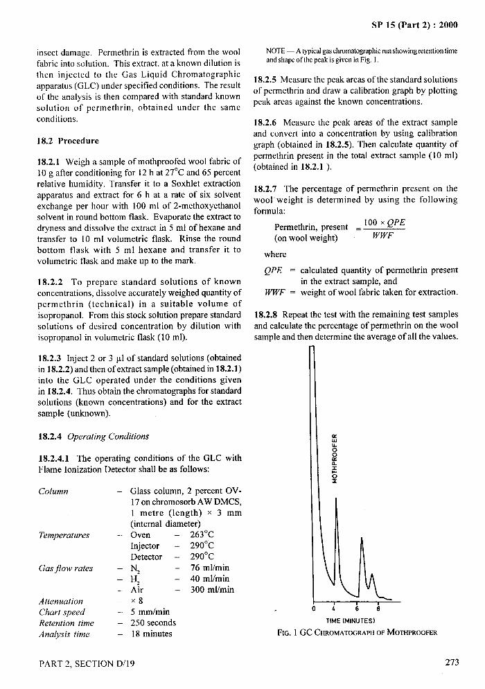
SP 15 (Part 2) :2000
insect damage. Permethrin is extracted from the woolfabric into solution. This extract, at a known dilution isthen injected to the Gas Liquid Chromatographicapparatus (GLC) under specified conditions. The resultof the analysis is then compared with standard knownsolution of permethrin, obtained under the sameconditions.
18.2 Procedure
18.2.1 Weigh a sample of mothproofed wool fabric of10 g after conditioning for 12 hat 27°C and 65 percent
relative humidity. Transfer it to a Soxhlet extractionapparatus and extract for 6 h at a rate of six solventexchange per hour with 100 ml of 2-methoxyethanolsolvent in round bottom flask. Evaporate the extract todryness and dissolve the extract in 5 ml of hexane andtransfer to 10 ml volumetric flask. Rinse the roundbottom flask with 5 ml hexane and transfer it tovolumetric flask and make up to the mark.
18.2.2 To prepare standard solutions of knownconcentrations, dissolve accurately weighed quantity ofpermethrin (technical) in a suitable volume ofisopropanol. From this stock solution prepare standard
solutions of desired concentration by dilution withisopropanol in volumetric flask (1 O ml).
18.2.3 Inject 2 or 3 @ of standard solutions (obtainedin 18.2.2) and then of extract sample (obtained in 18.2.1)into the GLC operated under the conditions givenin 18.2.4. Thus obtain the chromatography for standardsolutions (known concentrations) and for the extractsample (unknown).
18.2.4 Operating Conditions
18.2.4.1 The operating conditions of the GLC withFlame Ionization Detector shall be as follows:
Column —
Temperatures –
Gas jlow rates –—
—
Attenuation –Chart speed –Retention time –
Analysis time —
Glass column, 2 percent OV-17 on chromosorb AW DMCS,1 metre (length) x 3 mm(internal diameter)Oven – 263°C
Injector – 290”C
Detector – 290”C
N, – 76 ml/min
H, – 40 ml/min
Air – 300 ml/minX85 mm/min250 seconds18 minutes
PART 2. SECTION D/19
NOTE — Atypical gaschmrnatographicrunshowingretentiontimeand shape of the peak is given in Fig. 1.
18.2.5 Measure the peak areas of the standard solutionsof perrnethrin and draw a calibration graph by plottingpeak areas against the known concentrations. ‘“,1
18.2.6 Measure the peak areas of the extract sampleand convert into a concentration by using calibrationgraph (obtained in 18.2.5). Then calculate quantity ofpermethrin present in the total extract sample (1 O ml)(obtained in 18.2.1 ).
18.2.7 The percentage of permethrin present on thewool- weight is determined by using the followingformula:
Permethrin, present = 100x ‘PE(on wool weight) WWF
where
QPE = calculated quantity of permethrin presentin the extract sample, and
WWF = weight of wool fabric taken for extraction.
18.2.8 Repeat the test with the remaining test samplesand calculate the percentage of perrrtethrin on the woolsample and then determine the average of all the values.
TIME (MINUTES)
FIG. 1 GC CHROMATOGRAPHYOFMOTHPROOFER
273
/
SP 15 (Part 2) :2000..—
19 ESTIMATION OF 2-PHENYLPHENOL (OPP)
19.0 Principle
2-phenylphenol is extracted from the textile by steamdistillation. An aliquot of the extract is treated withdiazotized sulphanilic acid which forms a solublecoloured complex with 2-phenylphenol. The opticaldensity of the complex is measured on a suitablespectrophotometer at 460 nm.
19.1 Reagents
19.1.1 Orthophosphoric Acid – 90 percent (m/m),
19.1.2 Sodium Hydroxide – 80 g/1 solution.
19.1.3 Sodium Hydroxide – 10 g/1 solution.
19.1.4 Sodium Nitrite – (0.05 M solution), prepared by
dissolving 0.85 g sodium nitrite in water and makingup to 250 ml with water. The solution should be preparedfresh before use.
19.1.5 Sulphanilic Acid – 0.5 M solution (approx),prepared by dissolving 1.91 g of sulphanilic acid in 250ml of water.
19.1.6 Sulphuric Acid – (4.5 M), carefully dilutesulphuric acid concentrated 98 percent (m/m) to fourtimes.
19.1.7 Diazotized Sulphanilic Acid Solution – Thissolution should be prepared immediately before use byadding 1 volume of sulphuric acid 4.5 M to 5 volumesof sulphanilic acid solution, cooling to 10°C and slowlyadding to the solution 5 volumes of the sodium nitritesolution.
19.1.8 2-Phenylphenol Standard Solution (1 g/1) –
prepared by dissolving 0.100 g of the reagent in100 ml of the sodium hydroxide (10 g/1) solutionand made up to 100 ml in a standard flask withsodium hydroxide. 2 -phenylphenol standardreference solution, prepared by diluting 10.0 ml ofthe standard solution (1 g/1) with sodium hydroxide(10 g/1) solution to 100 ml. 1 ml = 100 pg2-phenylphenol.
19.2 Procedure
19.2.1 Weigh 5.0 g of the material, cut into smallpieces of not more than 5 mm square and place in a
500-ml round bottomed flask, with a suitable glassground socket. Add 200 ml of water and 3 mlorthophosphoric acid reagent. Connect the flask forsteam distillation and steam distill the contents ofthe flask, ensuring that a constant volume ismaintained by applying gentle heat as necessary.Collect 500 ml of the distillate, taking precautions toprevent the distillate becoming warm at any stage ofthe distillation.
19.2.2 Make up the volume of distillate to a knownvolume by addition of water. If the volume of distillateis 500 ml, take a suitable aliquot of not greater than25 ml, dilute with water to 30 ml, add 10 ml of thediazotized sulphanilic acid solution followed by 5 ml of
sodium hydroxide (80 g/1 ) solution and make up to50 ml with water. Allow to stand for 1 hour, then
determine the optical density of the solution on a suitablespectrophotometer at 460 nm using water as a blank;Estimate the 2-phenylphenol content by reference toa calibration graph made from known standards of2-phenylphenol (see 19.2.3.2).
19.2.3 Transfer by burette 1.0, 2.0, 3.0, 4.0, 5.0, 6.0and 7.0 ml of 2-phenylphenol standard reference solution
to a series of 50-ml standard flasks. To each of theseven flasks and to an empty flask add water to bringthe total volume to 30 ml. Then add 10 ml of thediazotized sulphanilic acid reagent followed by 5 ml ofthe sodium hydroxide (80 g/1 ) solution and makeup to50 ml with water.
19.2.3.1 Allow to stand for 1 hour and determine the
optical density of the solutions at 460 nm using thesample containing no 2-phenylphenol in the referencecell.
19.2.3.2 Draw a graph by plotting optical density againstconcentration of 2-phenylphenol.
NOTE— The range of the method is 0.01 percent to 1.4 percent2-phenylphenol.
20 ESTIMATION OF TRIBUTYLTIN OXIDE
(TBTO)
20.0 Principle
The material is subjected to wet oxidation, the tin inacid solution is solvent extracted. The tin is extracted
from the organic solvent and the colour developedwith catechol violet is measured by a suitablespectrophotometer at a wavelength of552 nm.
274 PART 2. SECTION D/l 9
I
II
,A-“-. ..—
SP 15 (Part 2) :2000
20.1 Reagents
20.1.1 Toluene – low in benzene.
20.1.2 Ammonia Solution – 5 M reagent.
20.1.3 Ascorbic Acid – 5 percent (50 gll aqueousreagent solution) – The solution should be preparedfreshly.
20.1.4 Hydrochloric Acid – 5 M.
20.1.5 Potassium Iodide – 5 M (830 g/1) reagent solutionprepared by dissolving 83 g potassium iodide in 70 ml
water, then diluting to 100 ml with water. The solution
should be prepared freshly.
20.1.6 Sodium Hydroxide – 5 M.
20.1.7 Sodium Acetate Trihydrate – 200 g /1 reagentsolution. Reagent to be free of fi.mgal growth.
20.1.8 Sodium Hydroxide – 0.1 M.
20.1.9 Sulphuric Acid Concentrated – 98 percent(m/m), 18 M.
20.1.10 Sulphuric Acid – 4.5 M.
20.1.11 Nitric Acid Concentrated, 70 percent (m/m)(16 M).
20.1.12 Tin (IV) Stock Solution – 0.20 mg/ml Sn,prepared by dissolving 0.100 g pure granulated tin in20 ml concentrated sulphuric acid. Heat until fumesappear then, cool before cautiously diluting with 150ml of water. Cool again before adding 65 ml sulphuric
acid concentrated, cool and transfer to a 500 mlvolumetric flask and make up to volume with water.
20.1.13 Tin ( IV) Standard Reference Solution – 10.0 pgl
ml Sn, prepared by diluting 5.0 ml of Tin (IV) stocksolution to 100 ml with water. This solution should beprepared when required.
20.1.14 Catechol Violet – 0.05 g/100 ml in water. This
solution should be freshly prepared.
20.2 Procedure
20.2.1 Weigh accurately 1.0 g of the material, transferto a 200-ml Kjeldahl flask, add 10 ml of sulphuric acidconcentrated followed by the addition of nitric acid
(16 M) 1-2 ml at a time. Apply gentle heat and digest --5--,with the further addition of nitric acid (16 M) until all ~
organic matter is completely destroyed. Evaporate untilfuming; cool, add 10 ml of water and boil to remove ,J,.,. .. ...nitric fumes, evaporate again until fuming. Cool, add
30 ml water.
20.2.2 If the tin content is expected to comply with thelight process (or less than 0.05 percent tin) transfer the
solution, filtered if necessary, to a 100-ml graduated flaskusing sulphuric acid (4.5 M) and dilute to the mark with
this acid.
20.2.3 If the tin content is expected to comply with the
normal process (or greater than 0.05 percent tin) transfer
the solution, filtered if necessary to a 250-ml graduatedflask using sulphuric (4.5 M) and dilute to the markwith this acid.
20.2.4 Take a suitable aliquot of solution prepared asin 20.2.2 or 20.2.3 of not greater than 25 ml and not
containing greater than 40 pg of tin and transfer to a50-ml separating funnel. Add 2.5 ml potassium iodide
(5 M) solution, mix and add 10 ml toluene. If, however,the volume of test solution taken exceeds 25 ml, add 1.0ml potassium iodide for each 10.0 ml solution in excessof 25 ml. Insert the stopper, shake the funnel vigorouslyfor 2 minutes, allow the layers to separate and discardthe aqueous phase. Wash the toluene layer by swirling
but without shaking with 5 ml of a solution prepared by
mixing 25 ml sulphuric acid (4.5 M) and 2.5 mlpotassium iodide solution. Discard the washing (Aflereach of the operations using potassium iodide, wash
below the separating funnel tap with water. It isadvisable to rinse the funnel exit tubes free of potassiumiodide since failure to do so may create unsightly stains
following subsequent shaking). Add 5 ml of water tothe toluene extract and then sodium hydroxide (5 M)solution dropwise with thorough shaking until thetoluene layer is colorless. ~This usually requires six to
ten drops of the reagent), (add a further two drops ofsodium hydroxide (5 M) reagent, insert the stopper and
shake the fimnel for 30 seconds. Allow the layers toseparate and run the aqueous layer into a 50 m 1beaker,
ensuring that all liquid below the tap is transferred tothe beaker. Add 3 ml sodium hydroxide (O.1 M solution)to the toluene layer, stopper the funnel then invert and
shake for 30 seconds. Allow the layers to separate andadd the aqueous layer to the contents of the 50 ml beaker.Retain the toluene layer.
20.2.5 Acidify the aqueous layer in the beaker with2.5 ml hydrochloric acid and decolonize the liberated
\
PART 2, SECTION D/l 9 275
/
.SP 15 (Part 2) :2000
iodine by the dropwise addition of ascorbic acidsolution. Add 2.0 ml catechol violet solution and mix.
Wash the toluene layer retained in 20.2.4 by swirling
(but without shaking) with 5 ml sodium acetatesolution. Add these washings to the contents of thebeaker, mix and adjust the pH of the solution to 3.8 +0.1 with ammonia solution by means of a pH meter.Transfer the solution to a 25-ml standard flask, diluteto the mark with water, and allow to stand for 30minutes. Measure the optical density of the solution
on a suitable spectrophotometer at a wavelength of 552nm using a 10 mm cell.
20.3 Calculation
20.3.1 Calculate the tin content by reference to acalibration graph prepared from known standards of tin.
20.4 Calibration
Transfer by microburettes 0.5, 1.0, 1.5, 2.0, 2.5, 3.0
and 4.0 ml of tin (IV) standard reference solution to aseries of 50-m I beaker. To each of these beakers andalso to an empty 50-ml beaker add water to bring the
total volume to 7.0 ml. To each, add in the orderindicated (which must be strictly adhered to) thefollowing reagents: 1.0 ml sodium hydroxide (5 M)
solution mix; 2.5 ml hydrochloric acid solution, mix;2.0 ml catechol violet solution, mix again; then add5.0 ml sodium acetate solution. Adjust the pH of thesolution to 3.8 + 0.1 with ammonia solution using apH meter. Transfer each solution to separate 25-ml
standard flasks, dilute each to the mark with water andallow to stand for 30 minutes. Measure the opticaldensity of each of the solutions in a 10-mm cell at 552nm with the solution containing no tin in the referencecell. Construct a graph relating the optical densityagainst concentration of tin.
NOTE — The graph should be rectilinear and pass through theorigin. Since not all batches of catechol violet behave with equalsensitivitytowardstin,recalibrationisadvisedwhena differentbatchofcatechol violet is used.
21 ESTIMATION OF HALOGENATEDDIPHENYL UREA DERIVATIVE (HDUD)
General
The method is applicable to the determination of HDUDon wool or on the woollen portion of blends of woolwith nylon. It can also be used for blends of other animalfibres with nylon.
21.1 Principle
21.1.1 If no fibre other than wool (or other animal fibre)is present, the textile to be analyzed is dissolved inaqueous potassium hydroxide solution and the HDUDis hydrolyzed to form 3:4 dichloroaniline.
21.1.2 If the textile consists of a mixture of wool (orother animal fibre) and nylon, the woolen (or otheranimal fibre) part of the material to be analyzed isdissolved in an aqueous 50 percent potassium hydroxidesolution and separated from undissolved nylon fibres.The HDUD is hydrolyzed to form 3:4 dichloroaniline.
21.1.3 The amine so obtained is isolated from thealkaline solution by steam distillation and is thendiazotized and coupled with benzoyl-H-acid to form ared water-soluble dye. The amount of this dye isdetermined calorimetrically.
21.1.4 This method is not specific to HDUD. Othercompounds, such as certain water-soluble dyes, can alsoproduce a red, water-soluble dye by this method, whichcan, therefore, interfere with the HDUD determination.However, this has not been found to be a seriousdrawback in practice and the calorimetric method ofestimation has been found to be reliable.
21.2 Apparatus
21.2.1 Apparatus for the Separation of Wool and NylonFibres – if required.
21.2.1.1 Waterbath – capable of maintaining at 175mm x 30 mm boiling tube at 71 + 1°C.
21.2.1.2 Sintered glass fimnel – porosity grade 1
21.2.1.3 Buchner$lterflask – 500 ml capacity,
21.2.2 Distillation Apparatus
21.2.2.1 Round bottom j?ask – alkali resistant, of1000 ml capacity.
21.2.2.2 Distillation splash head – bulb diameterapproximately 70 mm, fitted with a 19/9 ground glassjoint on the base and a 24/1 O ground glass joint at theend of the distillation tube.
21.2.2.3 Bulb condenser – fitted with a 24/1 O ground
glass socket. Length of the cooling jacket 25 to 30 cm.
21.2.2.4 One-mark volumetric jlasks – 1 000 ml,250 ml and 100 ml.
—.+-y
!
.-
\.i,
276 PART 2, SECTION D/l 9
SP 15 (Part 2) :2000
I 21.2.2.5 Gus burner or electric heater
F
21.2.3 Water Bath – capable of being controlled at10 to I2“C.
21.2.4 Spectrophotorneter – suitable for themeasurement of absorbance (optical density) at awavelength of 503 nm.
21.3 Reagents
21.3.1
21.3.2
21.3.3
21.3.4
21.3.5
21.3.6
Potassium Hydroxide Solution – 500 gll.
Potassium Hydroxide Solution – 2.5 M.
Hydrochloric Acid Solution – 1.0 M.
Sodium Hydrogen Carbonate Solution – 1.0 M.
Sodium Nitrite Solution – 0.1 M.
Benzoyl-H-Acid – (that is, l-benzolyamino-8-
hydroxynaph~halene-3, 6-disulphonic acid), 0.01 Msolution. The solution should be renewed and stored inan amber coloured bottle.
21.3.7 3,4 - Dichloroaniline – 0.001 M standardsolution. Weigh to the nearest 1 mg, 162 mg of 3,4-dichloroaniline and dissolve in. 10 ml of 1 Mhydrochloric acid solution, heating, if necessary, ona boiling water bath until completely dissolved.Transfer the solution quantitatively to a 1000 ml one-mark volumetric flask, dilute to the mark and mixwell.
21.3.8 High Vacuum Grease or Soft Paraffin – for jointlubrication.
21.3.9 Silicone Antlfoam
21.4 Procedure
21.4.1 Dissolution of Wool or Other Animal Fibres
21.4.1.1 Wool and nylon mixtures
If the textile material to be analyzed is a mixture ofwool (or other animal fibre) with nylon, proceed as givenin 21.4.1.2 to 21.4.1.5.
21.4.1.2 Put 0.5 + 0.001 g of the conditioned materialto be analyzed into a boiling tube. Place the tube on thewater-bath controlled at 71 + 1‘C and add 20 ml of the500 g/1 potassium hydroxide solution at about 20°C.
PART 2, SECTION D/19
Stir with a glass rod for exactly 5 rein; within this periodthe wool dissolves. Filter immediately through the filterfunnel into the Buchner filter flask and drain withsuction. Rinse the boiling tube and the nylon residuethree times with water, using a total of about 100 ml.To improve the rinsing effect, squeeze the residue withthe help of tongs and then drain the filter crucible withsuction.
21.4.1.3 Dry the nylon residue in the oven at 105 + 2°Cfor 3 h, recondition and determine its mass to an accuracyof O.oolg.
21.4.1.4 Transfer the filtrate to the distillation flaskand rinse the Buchner filter flask with about 30 ml ofwater.
21.4.1.5 Add a few drops of the silicone antifoam and afew chips of unglazed porcelain to the dissolved woolsolution in the distillation flask. Grease the ground glassjoints with the high vacuum grease of sofl paraffin andassemble the distillation apparatus. Place a 100-mlvolumetric flask, containing 6 ml of the hydrochloricacid solution, together with a funnel under the condenser.Complete the estimation of HDUD as given in 21.4.2to 21.4.5.
21.4.1.6 Wool and other animal>bres
If no fibre other than wool (or other animal tibre) ispresent, proceed as given in 21.4.1.7.
21.4.1.7 Place 0.5 + 0.001 g of the conditioned materialto be analyzed in a distillation flask. Add 140 ml of the2.5 M potassium hydroxide solution together with a fewchips of unglazed porcelain and a few drops of thesilicone antifoam.
–-J
,. .,..-1‘4
Complete the asembly of the apparatus as in 21.4.1.5and the estimation of HDUD as given in 21.4.2to 21.4.5.
21.4.2 Hydrolysis and Distillation
Heat the contents of the distillation flask (obtained
either in 21.4.1.5 or 21.4.1.7) to the boiling pointand maintain at the boiling point for 15 min. Thendistil about 90 ml within 20 to 50 minutes. During
distillation, ensure that neither the alkaline solution
nor any foam passes through the distillation splashhead into the condenser. Cool the distillate in the
volumetric flask to 20°C, dilute to the mark and mixwell.
277.
/
SP 15 (Part 2) :2000
,4,
...—
21.4.3 Diazotization
Measure 50 ml of the contents of the 100-ml volumetricflask into a 250-ml volumetric flask and cool to 10 to12°C (The remaining 50 ml of the distilate may beused for a check.). Add 1 ml of the sodium nitritesolution (O.1 M) and allow to stand for 10 rein, protectedfrom light, while cooling to 10 to 12°C.
21.4.4 Coupling
Add 15 ml of the sodium hydrogen carbonate solution(1.0 M) and, while shaking, add 3 ml of the benzoyl-H-acid solution. After 10 rein, dilute the solution withwater to 250 ml or to a volume more appropriate to theintensity of the colour of the solution.
solution and 1.5 ml of sodium nitrite solution, shakewell and cool once again to 10- 12“C. Allow the solutionto stand protected from light for 15 min and then add15 ml of the sodium hydrogen carbonate solution and 3ml of the benzoyl-H-acid solution. Shake, allow to standfor 10 rein, transfer quantitatively to a 100 ml one-markvolumetric flask, dilute to the mark and mix well.
21.5.3 Calorimetric Measurement
After colour development, measure the absorbance ofthe standard solutions in the spectrophotometer at awavelength of 503 nm against water in the referencecell.
21.5.4 Plotting the Calibration Graph
21.4.5 Calorimetric Determination of HDUD Deduct the absorbance of the reagent blank from thoseof the standard solution. Plot a graph having the
Measure the absorbance (optical density) of the percentage of HDUD as abscissae against the
solution in the spectrophotometer at wavelength of corresponding values of absorbance as ordinates.
503 nm against water in the reference cell andsubtract the absorbance of the reagent blank. 21.6 Expression of Results
Determine the content of the HDUD in the testedsample from a calibration graph.
21.6.1 Wool and Other Animal FibresHDUD percent= HDUDC percent
21.5 Preparation of the Calibration Graph where
21.5.1 Preparation of the Standard SolutionHDUDCC percent is the HDUD content as obtained fromthe calibration graph, and
To a series of six 1000 ml round bottom flasks, transferHDUD percent is the HDUD content of a conditionedsample of the material.
measured quantities of the standard 3,4 dichloroanilinesolution shown in the following table: 21.6.2 Wool/nylon mixtures
Standard
3, 4-Dichloroaniline
CorrespondingPercentage of HDUD’)
ml02)
4
8121620
Percento
0.22
0.45
0.67
0.901.12
HDUDC’?40X 0.5HDUD percent=
0.5 –gn
where
HDUDC percent is the HDUD content as obtainedfrom the calibration graph,HDUD percent is the HDUD content of the woolportion of a wool/nylon mixture sample, andgn is the conditioned mass of the nylon part of a woolJnylon mixture as obtained in 21.4.1.3.
21.5.2 Colour Development 22 ESTIMATION OF PHENOL CONTENT OF
TEXTILES TREATED WITH TAR OILTreat the contents of each flask as follows.
22.0 Principle21.5.2.1 Dilute with approximately 30 ml of water andcool it to 10- 12“C. Add 4 ml of the hydrochloric acid The phenols in a dried acetone extract of the material
are determined by titration of the extract with a standard,)~~lC,,l~ted~“5~[,loro-2.(z.s11[P110-4+!llorop11enoxy}Y,4-dicl1l0r,N N-diph~ylureasodiumsalt,I H,O (molecularweight562.2). solution of potassium hydroxide in propane-2-ol. The‘}Reagentblank. test is based on the exothermic conversion of acetone to
—.-4-1?
i
.
278 PART 2, SECTION D/19
SP 15 (Part 2) :2000
diacetone alcohol which is catalyzed by the free Let G be the mass of benzoic acid taken and x the .-
potassium hydroxide present at the end point. quantity in ml of potassium hydroxide solution, then
22.1 Apparatus Concentration (M) = *. ~2~ ~ ~ ‘-”””~,!),
22.1.1 Automatic Zero Burette 22.3 Procedure
100 ml capacity, 0.05-ml divisions, additional fine jet
such as hypodermic needle to deliver 0.3-0.5 ml of titrantper minute with a full burette and tap fully open. Theneedle is connected to the burette by a short piece offlexible tubing to make a butt joint.
22.1.2 PTEF Sleeve — to prevent titrant attack on jointof burette.
22.1.3 Titration Vessel – 100-ml tall. form beaker.
22.1.4 Thermometer – 15 to 45 ‘C.
22.1.5 Magnetic Stirrer — with polyethylene or PTFEcoated follower.
22.1.6 Soxhlet Extraction Apparatus, 60 ml capacitywith 150 ml flask B 19 neck.
22.1.7 Liebig Condenser, B 19 Socket.
22.1.8 Claisen Head, B 19 joints.
22.1.9 Anti-bumping Glass Beads
22.2 Reagents
22.2.1 Acetone (dry and free from acidity as possible).
22.2.2 Benzoic Acid
22.2.3 Toluene
22.2.4 Potassium Hydroxide in Propan-2-ol— ( 1 M )
standard volumetric solution-prepared by dissolving 56g of potassium hydroxide in dry propan-2-ol and dilutingto 1000 ml with propan-2-ol Standardize the solution
in the following manner.
22.2.4.1 Weigh accurately about 0.4 g of benzoic acidreagent and dissolve in 30 ml of acetone in the titration
‘vessel. Titrate the solution with the potassium hydroxidesolution by the method described under 22.3 until a steeptemperature rise is obtained. Read the volume ofpotassium hydroxide used.
Weigh accurately about 3 g of the material (more if
the tar oil treatment is light) and place directly in the
Soxhlet apparatus. Add 90 ml acetone to the flask
and three glass beads (to prevent bumping) and extract
for 2 hours or until the acetone becomes clear. After
extraction is complete, allow the apparatus to cool
then remove the flask and connect it to the condenser
by means of the Claisen head. Distill off 50 ml
acetone, add 30 ml toluene to the residual acetone
extract in the flask and re-distil, reducing the volume
of the extract to about 15 ml. Transfer the residual
extract to the 100-ml beaker, and wash out the flask
with small amounts of toluene. Transfer the washings
to the extract in the beaker and add 50 ml of acetone.
Place the follower and thermometer in the beaker and
switch on stirrer. Fill the burette with the standardized
potassium hydroxide solution, place the discharge end
of the hypodermic needle (which is fitted to the
automatic burette) below the surface of the contents
of the beaker and start the addition of titrant by
opening the burette tap fully, stirring continuously.
Observe temperature and immediately a rise is
evident, switch off the burette and read the volume of
potassium hydroxide used (A). A blank titration
experiment should be made using similar quantities
of reagents as in the actual analysis to determine the
correction for acidity in the reagents (B).
22.4 Calculation
P=(A-B)x Mx140x I00
1000 w
where
P = percentage of phenol present,
A = ml of potassium hydroxide used,
B = ml of potassium hydroxide in blank titrationexperiment,
M= molarity of potassium hydroxide, and
W = mass of sample taken.
i ml of 1 M potassium hydroxide solution = 0.122 g NOTE — 140 istakenasthe averagemolecularweightof thephenolsbenzoic acid. present.
PART 2. SECTION D/19 279
.#_..L?
SP 15 (Part 2) :2000
23 ESTIMATION OF DICHLOROPHEN5,5’-DICHLOR 2,2’ – DIHYDROXYDIPHENYLMETHANE
23.0 The method is applicable to the determination ofdichlorophen in textile materials provided that otherphenolic materials are absent.
23.1 Reagents
23.1.1 4-Aminophenazone — 10 gfl reagent solution,prepared by dissolving 1 g of reagent in 100 ml of buffersolution, pH 9.68.
23.1.2 Buffer Solution —pH 9.68 prepared bydissolving 13.75 g of disodium tetraborate and 1.125 gsodium hydroxide in water and diluting with water to1000 ml.
23.1.3 Potassium Periodate — 2.5 g/1 reagent solutionprepared by dissolving 1.25 g potassium periodate in500 ml of the buffer solution, pH 9.68.
23.1.4 Dichlorophen — standard reference solution(20 pg/ml) — prepared by dissolving 0.200 g ofdichlorophen, purified melting point 175°C in 10 mlacetone and diluting to 100 ml with the buffer solution.
23.2 Procedure — Extract 1 g of the proofed material(or sufficient to contain 10 mg dichlorophen) byboiling with four successive 25-ml lots of the buffersolution: each extraction should be allowed tocontinue for 7 minutes before decanting from thematerial. Combine the extracts, cool, add 100 mlbuffer solution and make up to 200 ml with water.Filter a portion and take 4.0 ml and place into a 50-ml volumetric flask. Dilute to about 35 ml with buffersolution and add by pippette 1.5 ml of the 4-aminophenazone reagent. Mix thoroughly then add10 ml of the periodate solution, dilute the solutionwith buffer solution to 50 ml and mix well. Controlthe temperature of the reaction within the range of17-20°C, protect the solution from light anddetermine the optical density of the solution at 510nm on a suitable spectrophotometer after not less than5 minutes using a reagent blank as zero.
23.3 Calibration – Prepare standard solutions bytaking 5,10 and 15 ml aliquots of the dichlorophenstandard reference solution, 20 pg/ml, dilute to about50 ml with buffer solution and proceed as describedin 23.2. Measure the optical density and plot thedata on a graph, optical density against pg ofdichlorophen.
10 ml of this solution diluted to 1000 ml with buffer 23.4 Calculate the dichlorophen content from a
solution is 20 ~g/ml. previously prepared calibration graph (see 23.3).
—
1,,,t.--,
“
k,’ .
\
280 PART 2, SECTION D/l 9
#—..,—
t
SP 15 (Part 2) :2000
DETERMINATION OF BARIUM ACTIVITY
NUMBER OF COTTON TEXTILE MATERIALS
(Source : IS 1689: 1973)
Apart from lustre the absorption capacity of cotton is greatly increased by mercerization. Mercerized cotton absorbssoluble alkaline hydroxides to a greater extent than unmercerized cotton. Barium hydroxide is more readily absorbedby cotton cellulose than other alkalis and its absorption is convenient to measure. This barium hydroxide absorptiontest is thus indicative of the cotton material having undergone the process of mercerization. If unmercerized cottonis indicated by Barium Activity .Number 100, the Barium Activity Number above 115 indicates that the sampleunder test has undergone the process of mercerization. This test can not be used satisfactorily on materials treatedwith durable finishes, or dyed with sulphuric dyes or if tibres other than cotton are present.
1 SCOPE 5 TEST SPECIMENS AND CONTROL SPECIMEN
This standard prescribes a method for determination of 5.1 Test Specimensbarium activity number of cotton materials.
5.1.1 If the sample under test is yarn, draw from it at2 TERMINOLOGY least three specimens each weighing about 3 g.
For the purpose of this standard, the following definitionshall apply.
Barium Activity Number – The ratio of the quantityof barium hydroxide absorbed by mercerized cotton tothat absorbed by unmercerized cotton under identicalconditions, multiplied by 100.
3 PRINCIPLE
A sample is taken and completely freed from all sizingand finishing materials. It is treated with bariumhydroxide to determine its absorption. The absorptionof an unmercerized cotton sample is also determinedunder identical conditions. The ratio of absorption oftest sample and unmercerized cotton sample is expressedas the barium activity number taking the unmercerizedcotton as 100.
4 SAMPLING
5.1.2 If the sample under test is fabric, draw from itthree specimens each weighing about 3 g and preferablysquare in shape.
5.2 Control Specimen
Draw from the basic (unmercerized, scoured) cottonmaterial a specimen weighing about 3 g.
NOTE — If the basic (unmercerized) material is not available, anunmercerized (scoured) cotton material similar in construction tothat under test shall be used for the control.
6 APPARATUS
6.1 Soxhlet Extractor
6.2 Drying-Oven
Capable of being maintained at a temperature of105 + 3°c.
4.1 Samples shall be selected so as to be representative 6.3 Conical Flask — with stopper.of the lot.
4.2 Sample drawn as laid down in the material6.4 Pipette
specification or in compliance with an agreementbetween the buyer and the seller shall be held to be
7 REAGENTS
representative of the lot. 7.1 Unless specified otherwise pure chemicals shall be
4.3 In case of cotton fabrics, the sample shall be drawnapplied in the test. Distilled water shall be used wherethe use of water as a reagent is intended.
in accordance with the procedure given in IS 5463:1969‘Methods for sampling of cotton fabrics for them ical NOTE — ‘Purechemicals’shallmeanchemicalsthat do not containtests’ given in Section A- 1/3. impuritieswhich at~ectthe results of the analysis.
. . ..
PART 2, SECTION D/20 281
I
I~’
II
SP 15 (Part 2) :2000
7.2 Chloroform
7.3 Diastase or Other
7.4 Sodium Chloride
Suitable Desizing Enzyme
7.5 Soap-Soda Solution
Containing 20 g of soap and 10 g of anhydrous sodiumcarbonate per litre. The soap shall contain not more than5 percent moisture and shall comply with the followingcomposition, dry mass basis:
Free alkali (as Na, CO,), Max
Free alkali (as NaOH), Max
Combined fatty acids (as sodiumsalt), &fin
Titre of mixed fatty acids preparedfrom the soap, Max
Iodine value of fatty acids, Max
7.6 Barium Hydroxide Solution
Approximately 0.25 N.
7.7 Hydrochloric Acid
0.05 N and 0.1 N.
7.8 Phenolphthalein Indicator
0.3 percent0.1 percent
85 percent
30°c
50
Prepared by dissolving 0.5 g of phenolphthalein in50 ml of ethyl alcohol and diluting to 100 ml with water.
8 PROCEDURE
8.1 Take one test specimen.
8.1.1 If the material under test is not heavily finished,desize the specimen as given in 8.1.1 .1,8.1.1.2 or 8.1.1.3depending on the type of ingredients used in the size orfinish.
8.1.1.1 [n case it is known that the material is sized orfinished with a mixing containing starch but not
tamarind kernel powder, dip the specimen in a solution(weighing 20 times the mass of the specimen) containing
5 g of diastase and 10 g of sodium chloride per Iitre at70°C and at a pH of 6.5 to 7.7 (see Note). Allow thespecimen to remain in the solution for one and a half
hours. During this period, take it out from the desizing
282
bath and wring it by hand at least three times. At theend of the period remove the specimen, wash it
thoroughly four times in hot and cold water successively,using 50 ml of water for each wash.
NOTE — The temperature andpH given for the desizing solutionare the optimum for bacterial diastase, If any other type of desizingenzyme is used, then the temperature andpH shall be modified tothat recommended by the supplier. As many enzymatic des+izingagents slowly deteriorate in storage, care shall be taken to see thattbe sampleof desizingagent,at tbe time of test, has still satisfactorydesizingetliciency.
Ifanydoubtexistsasto whetbertbesizeor tinisbhas beencompletelyremoved,thetreatmentwith the enzymaticdesizingsolutionshallberepeated,tbe specimenbeingagainweighedafterdryingto constantmass at 105 to 11O“C and tbe percentage loss in mass againcalculated.Ifthe value for the percentageloss in masshas increasedby not more than 0.25, then it may be considered that completedesizinghas been etTected,and the second value be accepted as thefinalvalue, Iftbe value fortbe percentageloss in mass bas increasedby more than 0.25, then tbe desizing treatment should be repeateduntil the figure for percentage loss in mass does not differ from tbeprevious figure by more than 0.25.
8.1.1.2 In case it is known that the material is sized orfinished with a mixing containing tamarind kernelpowder but not starch, boil the specimen in the soap-soda solution (weighing 20 times the mass of thespecimen) for 45 minutes. Wash it thoroughly first inhot water and then in cold water.
8.1.1.3 In case it is known that the material is sized or
finished with a mixing containing both starch andtamarind kernel powder or in case the ingredients used
in the size or finish are not known, desize the specimenin the manner prescribed in 8.1.1.1 for the specimenknown to contain starch and treat it further in the mannerprescribed in 8.1.1.2 for the specimen known to contain
tamarind kernel powder.
8.1.2 If the material under test is heavily finished with
mineral oils and waxes or with salts, extract the specimen
with chloroform in a Soxhlet extracting apparatus for
one hour, and then desize the specimen as given in 8.1.1.
8.1.3 Add bromocresol purple to the water extract of
the sample and add dilute hydrochloric acid (0.05 N to
0.1 N) drop by drop till it turns yellow. Keep the solution
for about 30 minutes. Remove the extract. Wash the
sample with distilled water till it is free from acid.
8.2 Dry the specimen and expose it to room atmospherefor about 4 hours. Cut the specimen into small pieces.Take exactly 2 g (on oven-dry basis) of the specimen.
PART 2, SECTION D/20
Iill~
4.— ---- —
SP 15 (Part 2) :2000
NOTE — For calculatingthe massof mercerizedand unmercerizedcotton to be taken for the test, the values of actual regainused areasgiven below:
Mercerizedcotton 9 percent
LJnmercerizedcottol] 6 percent
8.3 Transfer the specimen to a 50-ml conical flask andadd 30 ml of barium hydrodixe solution to it. Stopperthe flask and allow it to stand for at least 2 hours, withfrequent shaking. At the end of this period, pipette out
10 ml of the clear solution from the flask and titrate itwith hydrochloric acid using phenolphthalein asindicator.
8.4 Make a blank determination following the sameprocedure (see 8.3) but without the test specimen.
8.5 Treat the control specimen in a similar manner(see 8.1 to 8.3) along with the test specimen.
8.6 Similarly test other test specimens,
9 CALCULATION
9.1 Calculate the barium activity number by thefollowing formula:
Barium activity number =a–b—X looa–c
where
a = quantity in ml, of hydrochloric acid requiredfor the blank (see 8.4);
b = quantity in ml, of hydrochloric acid requiredfor the test specimen (see 8.3); and
c = quantity, in ml, of hydrochloric acid requiredfor the control specimen (see 8.5).
9.2 Calculate the barium activity number of other testspecimens and determine the average of all valuesobtained.
10 REPORT
The report shall include the following information:
a) Type of material tested,
b) Number of test specimens, and
c) Barium activity number.
_..—
““,,
PART 2. SECTION D/20 283
I
!’
I I
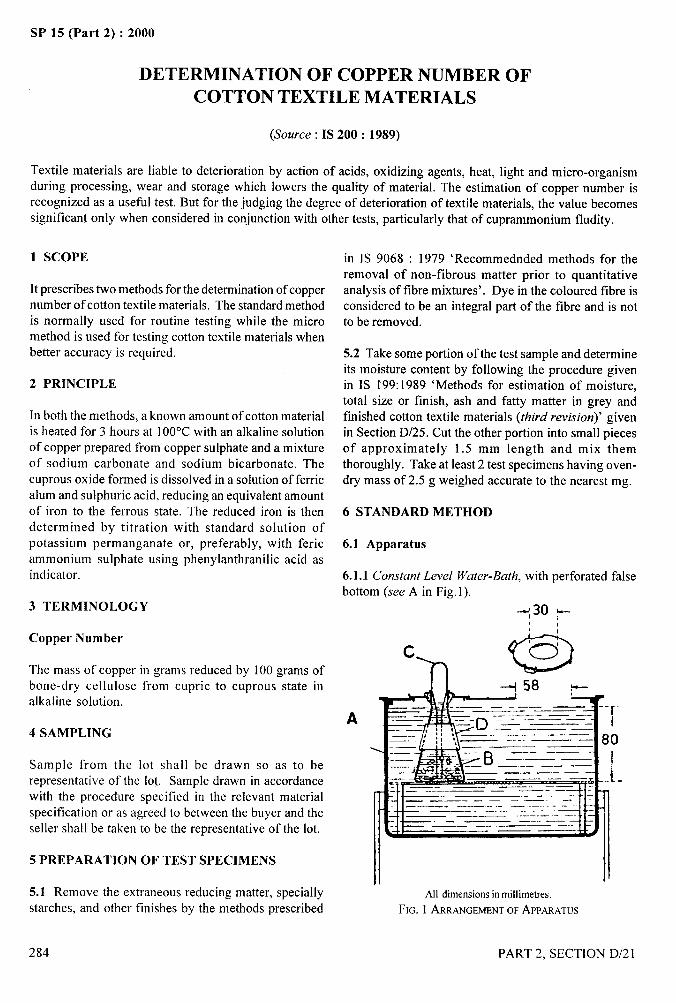
SP 15 (Part 2) :2000
DETERMINATION OF COPPER NUMBER OFCOTTON TEXTILE MATERIALS
(Source: IS 200: 1989)
Textile materials are liable to deterioration by action of acids, oxidizing agents, heat, light and micro-organismduring processing, wear and storage which lowers the quality of material. The estimation of copper number isrecognized as a useful test. But for the judging the degree of deterioration of textile materials, the value becomessignificant only when considered in conjunction with other tests, particularly that of cuprammonium fludity.
1 SCOPE
It prescribes two methods for the determination of coppernumber of cotton textile materials. The standard methodis normally used for routine testing while the micromethod is used for testing cotton textile materials whenbetter accuracy is required.
2 PRINCIPLE
In both the methods, a known amount of cotton materialis heated for 3 hours at 100”C with an alkaline solutionof copper prepared from copper sulphate and a mixtureof sodium carbonate and sodium bicarbonate. Thecuprous oxide formed is dissolved in a solution of ferricalum and sulphuric acid, reducing an equivalent amountof iron to the ferrous state. The reduced iron is thendetermined by titration with standard solution ofpotassium permanganate or, preferably, with fericammonium sulphate using phenylanthranilic acid asindicator.
3 TERMINOLOGY
Copper Number
The mass of copper in grams reduced by 100 grams ofbone-dry cellulose from cupric to cuprous state inalkaline solution.
4 SAMPLING
Sample from the lot shall be drawn so as to berepresentative of the lot,. Sample drawn in accordancewith the procedure specified in the relevant materialspecification or as agreed to between the buyer and theseller shall be taken to be the representative of the lot.
5 PREPARATION OF TEST SPECIMENS
5.1 Remove the extraneous reducing matter, speciallystarches, and other finishes by the methods prescribed
284
in IS 9068 : 1979 ‘Recommended methods for theremoval of non-fibrous matter prior to quantitativeanalysis of fibre mixtures’. Dye in the coloured tibre isconsidered to be an integral part of the fibre and is notto be removed.
5.2 Take some portion of the test sample and determineits moisture content by following the procedure givenin IS 199:1989 ‘Methods for estimation of moisture,total size or finish, ash and fatty matter in grey andfinished cotton textile materials (third revision)’ givenin Section D/25. Cut the other portion into small piecesof approximately 1.5 mm length and mix themthoroughly. Take at least 2 test specimens having oven-dry mass of 2.5 g weighed accurate to the nearest mg.
6 STANDARD METHOD
6.1 Apparatus
6.1.1 Constant Level Water-Bath, with perforated falsebottom (see A in Fig. 1).
--530 *
A ro
‘-J‘“zB––-=:—n I_ ——. .— t——- —— ---— —-—.. ..—,Ji —-. –:- —-- – – -.–—= –--tl:
—c. —.- - —.—- .——.——. — . —— —~ .
IAll dimensionsin millimetres.
FIG. 1 ARRANGEMENTOFAPPARATUS
PART 2, SECTION D/21
—-,.-,
!
I
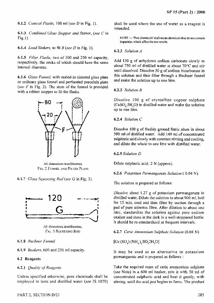
SP 15 (Part 2) :2000
6.1.2 Conical Flasks, 100 ml (see D in Fig. 1).
6.1.3 Combined Glass Stopper and Stirrer, (see C inFig.1).
6.1.4 Load Sinkers, to fit B (see Din Fig. 1).
6.1.5 Filter F[asks, two of 500 and 250 ml capacity,respectively, the necks of which should have the sameinternal diameter.
6.1.6 Glass Funnel, with sealed-in sintered glass plateor ordinary glass funnel and perforated porcelain plate(see Fin Fig. 2). The stem of the funnel is providedwith a rubber stopper to fit the flasks.
All dimensions in millimetres.
FIG. 2 FUNNELANDFILTERPLATE
shall be used where the use of water as a reagent is-.
intended.
NOTE — ‘Purechemicals’shall meanchemicals that do not contain ,----+
impuritieswhich affectthe test results. 1.
6.2.2 Solution A
Add 130 g of anhydrous sodium carbonate slowly toabout’ 750 ml of distilled water at about 70”C and stiruntil dissolved. Dissolve 50 g of sodium bicarbonate inthis solution and then filter through a Buchner funneland make the solution up to one Iitre.
6.2.3 Solution B
Dissolve 100 g of crystalline copper sulphate(CUS0,.5H20) in distilled water and make the solutionup to one litre.
6.2.4 Solution C
Dissolve 100 g of freshly ground ferric alum in about500 ml of distilled water. Add 140 ml of concentratedsulphuric acid slowly with constant stirring and cooling,and dilute the whole to one litre with distilled water.
6.2.5 Solution D
Dilute sulphuric acid, 2 N (approx).
6.2.6 Potassium Permanganate Solution ( 0.04 N)
6.1.7 Glass Squeezing Rod (see G in Fig. 3).The solution is,prepared as follows:
Dissolve about 1.27 g of potassium permanganate in
~ 120 -. ... .* distilled water. Dilute the solution to about 900 ml, boil0 for 15 rein, cool and then filter by suction through a4
G pad of pure asbestos tibre. After dilution to about one
A:L~~
litre, standardize the solution against pure sodiumoxalate and store in the dark in a well-stoppered bottle.It should be re-standardized at frequent intervals.
All dimensionsin millimetres.
FIG. 3 SQUEEZINGROD 6.2.7 Ceric Ammonium Sulphate Solution (0.04 N)
6.1.8 Buchner Funnel [Ce (S0,) (NH, )ZS0,2H,0]
6.1.9 Beakers, 600 and 250 ml capacity. It may be used as an alternative to potassium
6.2 Reagentspermanganate and is prepared as follows :
6.2.1 Quality of Reagents Take the required mass of eerie ammonium sulphate(see Note) in a 600 ml beaker, mix it with 50 ml of
Unless specified otherwise, pure chemicals shall be concentrated sulphuric acid and heat it gently, withemployed in tests and distilled water (see IS 1070) stirring, until the acid just begins to fume. The product
PART 2. SECTION D/21 285
I1’ II
1
SP 15 (Part 2) :2000
at this stage should be a lemon-yellow paste free fromlumps, cool and dilute it by the cautious addition of about
500 ml of water. The salt disolves readily, and when thesolution is cold, dilute it to one litre with water. Thissolution is stable but care should be taken not to store itin bottles whose surfaces have been etched in any way.The normal ity should be checked if the period of storageexceeds 2 months.
NOTE — The massoftbe solidreagentrequireddependson itspurityand shall be determined by a preliminary trial.
6.2.8 Phenylantht-anilic Acid Indicator
Dissolve anhydrous sodium carbonate (O.13g) in a smallquantity of hot water, add phenylanthranilic acid(0.266 g) to the solution, and then dilute to 250 ml.
6.2.9 Ferrous Ortho-Phenanthroline
Dissolve 1.49 g of ortho-phenanthroline monohydratein 100 ml of water containing 0.7 g of hydrated ferrous
sulphate.
6.3 Procedure
6.3.1 Place 2.5 .g of the material, previously cut intosmall pieces, into flask B.
6.3.2 Run 5 ml of solution B from a pipette into 95 mlof solution A contained in a 250 ml lipped beaker andraise the mixture to the boil. Then pour immediatelyinto flask B and mix thoroughly with the sample bymeans of a pear-bulb stirrer which afterwards serves asa loose stopper.
6.3.3 Weigh the flask by means of the load sinker andimmerse to the neck in the bath; close it as completelyas possible by means of a metal ring (see Fig. 1) andfinally pack round the neck with a short length of cottonsliver. Allow the flask to remain in boiling water for3 h and stir the contents occasionally during the first15 min to release air bubbles. Transfer the liquor and
6.3.4 Fit the funnel to the smaller filter flask and dissolvethe cuprous oxide by treatment with successive portionsof solution C; use the first portion to remove anyadhering cuprous oxide fi-om flask B before pouring intothe funnel. Two portions of the solution, 15 ml and10 ml respectively, usually suffice but an additional10 ml may occasionally be necessary. Wash the materialfinally with successive 15 ml portion of solution D. Priorto each addition of solution C or D release the suctionto ensure that the liquid saturates the fibrous materialthoroughly before being drawn into the flask; the ~connection to the filter pump should be provided with athree-way tap for this purpose.
6.3.5 Titrate the solution either with 0.04 N potassium
permanganate or preferably with 0.04 N eerieammonium sulphate. If the latter oxidant is used, addfour drops of phenylanthranilic acid indicator to thesolution before titration. The colour of the solution thenchanges from pale green to brownish purple whenoxidation of the ferrous iron is complete.
6.3.6 Ferrous-o-phenthroline indicator may be used, inwhich case the colour changes is from red to pale green.This indicator may also be used if the titration is carried
out with potassium permanganate. Similar colourchanges occur and the end point is much sharper thanif no indicator is used.
One millimetre of 0.04 N solution corresponds to0.002543 g of copper.
6.4 Expression of Results
6.4.1 Calculate the copper number Ncuby the formula:
N tx~x 0.002543x 100c“ =
2.5xm
where
t = the volume of 0.04 N solution (6.2.6 or 6.2.7)required,
f = the normality of the solution, andm = the correction for moisture content.
fibre to the funnel F and filter by suction through twolayers of filter paper (42.5 mm diameter) cut radially
NOTE— For most purposes, it is sufficient to assume an averagemoisture eontent, for example, 6 percent for cotton materials,
round the edges of facilitate fitting into the funnel. m =0.94.Wash the fla~k well, first with a dilute solution ofsodium carbonate and then with hot water, and pour 7 MICRO METHODthe washing over the sample’. Press the samplethoroughly with a glass squeezing rod (see Fig. 3) and 7.1 Principle
wash with further quantities of hot water. Reject thefiltrate and washings which have collected in the larger The sample of known mass is heated for 3 h at 100”C
filter flask. with an alkaline solution of copper prepared ffom copper
--
286 PART 2, SECTION D/21
I
i,l
1
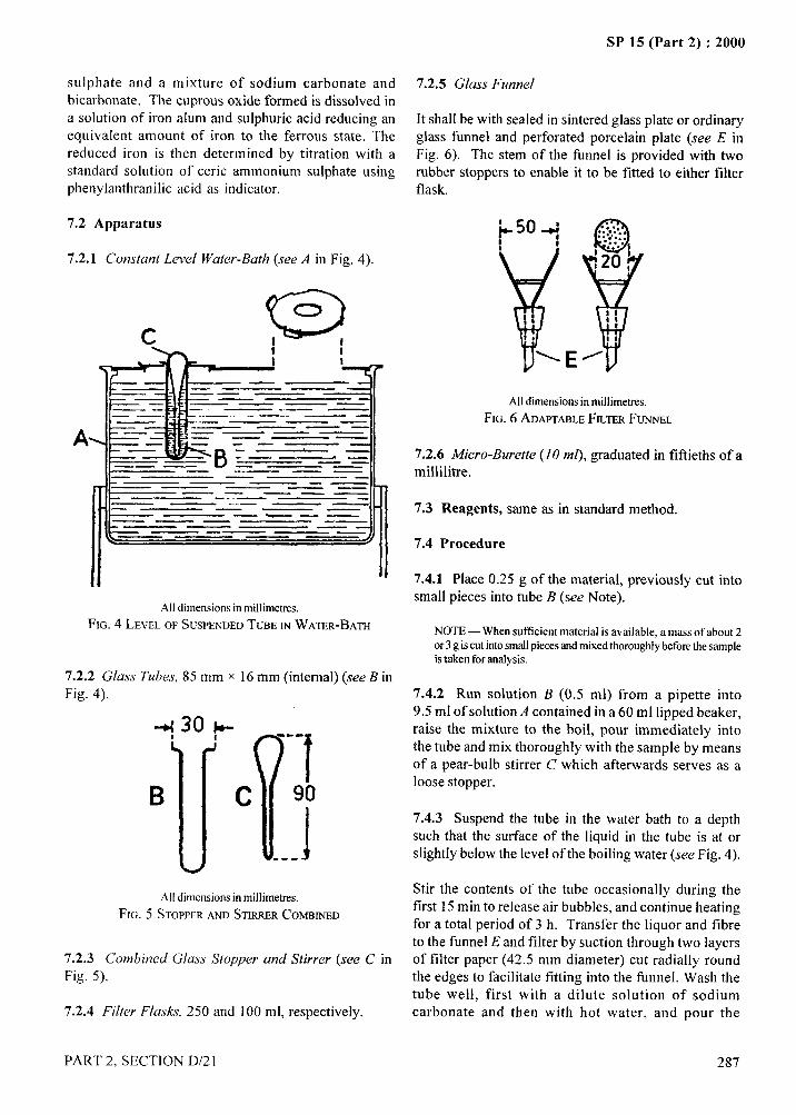
.4...-
SP 15 (Part 2) :2000
sulphate and a mixture of sodium carbonate and 7.2.5 Glass Funnel
bicarbonate. The cuprous oxide formed is dissolved ina solution of iron alum and sulphuric acid reducing an It shall be with sealed in sintered glass plate or ordinary
equivalent amount of iron to the ferrous state. The glass funnel and perforated porcelain plate (see E inreduced iron is then determined by titration with a Fig. 6). The stem of the funnel is provided with two
standard solution of eerie ammonium sulphate using rubber stoppers to enable it to be fitted to either filterphenylanthranilic acid as indicator. flask.
7.2 Apparatus
7.2.1 Constant Level Water-Bath (see A in Fig. 4).
,4
...
A
c
——. —
\
—— —.— .— ..—. .-.—.- ——. —————.—— —
——IL — ————== —.-11
All dimensionsin millimetres.
FIG. 4 LEVEL OF SUSPENDEDTUBEINWATER-BATH
7.2.2 Glass Tubes, 85 mm x 16 mm (internal) (see B inFig. 4).
+: 30 p= . . .
IJll
1B C 90
.. .1t
E
Q,..:,:.,............
Y:2(J
IIIs
I
la
Alldimensionsin miilimetres.
FIG. 6 ADAPTABLEFILTER FUNNEL
7.2.6 Micro-Burette (IO ml), graduated in fiftieths of a
millilitre.
7.3 Reagents, same as in standard method.
7.4 Procedure
7.4.1 Place 0.25 g of the material, previously cut into
small pieces into tube B (see Note).
NOTE— When sufficient material is available, amass of about 2or 3 g iscut intosmallpieeesandmixedthorough]y beforethesampleis taken for analysis.
7.4.2 Run solution B (0.5 ml) from a pipette into9.5 ml of solution A contained in a 60 ml lipped beaker,raise the mixture to the boil, pour immediately intothe tube and mix thoroughly with the sample by meansof a pear-bulb stirrer C which afterwards serves as aloose stopper.
7.4.3 Suspend the tube in the water bath to a depthsuch that the surface of the liquid in the tube is at orslightly below the level of the boiling water (see Fig. 4).
All dimensionsin millimetres.Stir the contents of the tube occasionally during the
Fm. 5 STOPPERAND STIRRERCOMBINEDfirst 15 min to release air bubbles, and continue heatingfor a total period of 3 h. Transfer the liquor and fibreto the funnel E and filter by suction through two layers
7.2.3 Combined Glass Stopper and Stirrer (see C in of filter paper (42.5 mm diameter) cut radially round
Fig. 5). the edges to facilitate fitting into the funnel. Wash thetube well, first with a dilute solution of sodium
7.2.4 Filter Flasks, 250 and 100 ml, respectively. carbonate and then with hot water, and pour the
PART 2, SECTION D/21 287
/
II
I I
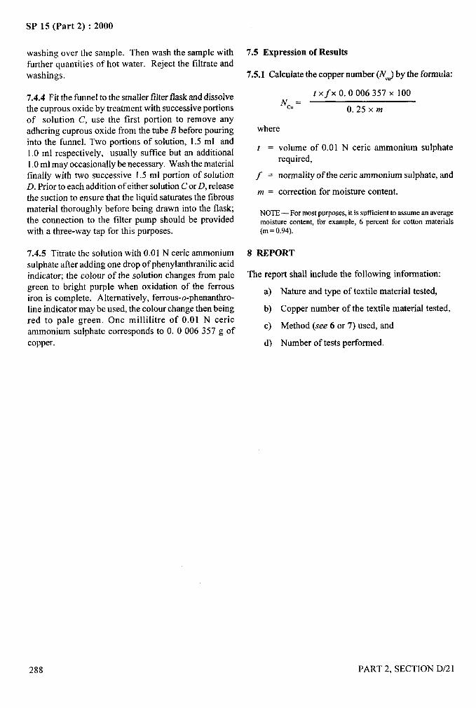
SP 15 (Part 2) :2000
washing over the sample. Then wash the sample withfurther quantities of hot water. Reject the filtrate andwashings.
7.4.4 Fit the funnel to the smaller filter flask and dissolvethe cuprous oxide by treatment with successive portionsof solution C, use the first portion to remove anyadhering cuprous oxide from the tube B before pouringinto the funnel. Two portions of solution, 1.5 ml and1.0 ml respectively, usually suffice but an additional1.0 ml may occasionally be necessary. Wash the materialfinally with two successive 1.5 ml portion of solutionD. Prior to each addition of either solution C or D, releasethe suction to ensure that the liquid saturates the fibrousmaterial thoroughly before being drawn into the flask;the connection to the filter pump should be providedwith a three-way tap for this purposes.
7.4.5 Titrate the solution with 0.01 N eerie ammoniumsulphate after adding one drop of phenylanthranilic acidindicator; the colour of the solution changes from pale
7.5 Expression of Results
7.5.1 Calculate the copper number (iVW)by the formula:
txfx O. 0006357 X 100NCU=
0.25xm
where
‘!
I —
——
t = volume of 0.01 N eerie ammonium sulphaterequired,
j = normality of the eerie ammonium sulphate, and
m = correction for moisture content.!!
NOTE — For most purposes, it is sutlicient to assume an averagemoisture content, for example, 6 percent for cotton materials(m= 0.94).
I
green to bright purple when oxidation of the ferrousa)
iron is complete. Alternatively, ferrous-o-phenanthro-line indicator may be used, the colour change then being b)red to pale green. One millilitre of 0.01 N eerieammonium sulphate corresponds to O. 0006357 g of
c)
copper. d)
Nature and type of textile material tested,
Copper number of the textile material tested,
Method (see 6 or 7) used, and
Number of tests performed.
PART 2, SECTION D/21
8 REPORT
The report shall include the following information:
288
..
.-
1
1,
,,
‘1
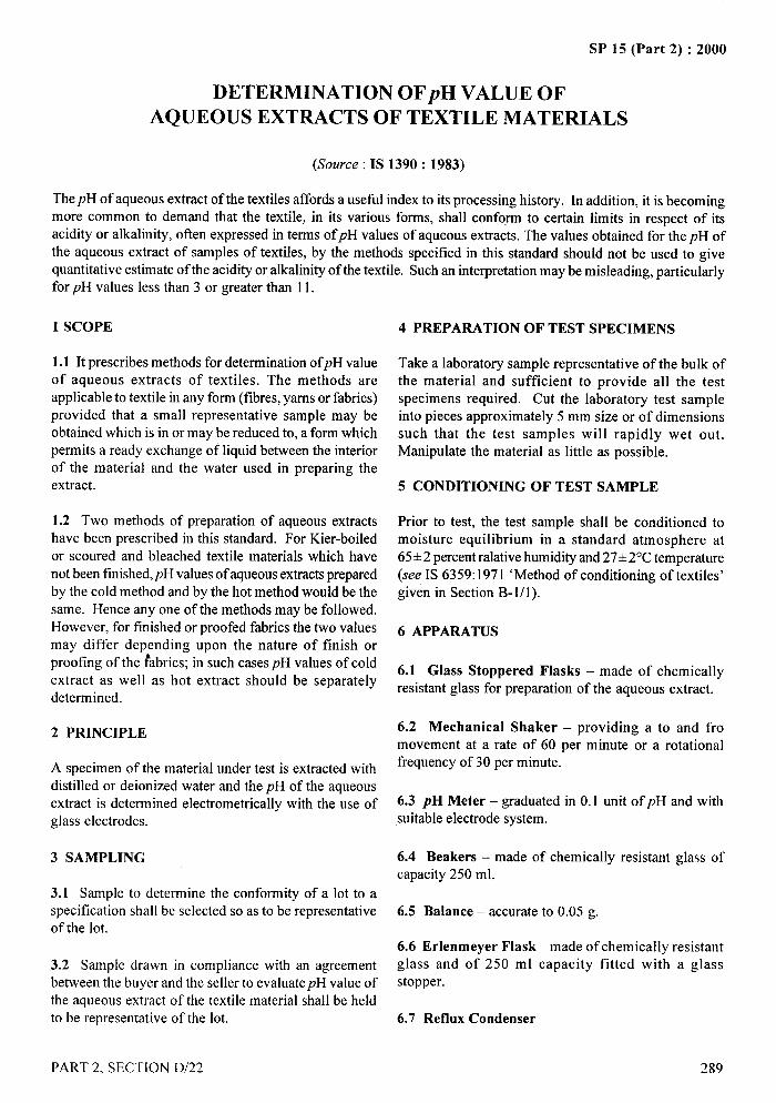
4—-
SP 15 (Part 2) :2000
DETERMINATION OFpH VALUE OFAQUEOUS EXTRACTS OF TEXTILE MATERIALS
($kwce: IS 1390: 1983)
ThepH of aqueous extract of the textiles affords a usefi.d index to its processing history. In addition, it is becomingmore common to demand that the textile, in its various forms, shall conform to certain limits in respect of itsacidity or alkalinity, often expressed in terms of pH values of aqueous extracts. The values obtained for the pH ofthe aqueous extract of samples of textiles, by the methods specified in this standard should not be used to givequantitative estimate of the acidity or alkalinity of the textile. Such an interpretation maybe misleading, particularlyfor pH values less than 3 or greater than 11.
1 SCOPE
1.1 Itprescribes methods for determination ofpH valueof aqueous extracts of textiles. The methods areapplicable to textile in any form (fibres, yams or fabrics)provided that a small representative sample may beobtained which is in or may be reduced to, a form whichpermits a ready exchange of liquid between the interiorof the material and the water used in preparing theextract.
1.2 Two methods of preparation of aqueous extractshave been prescribed in this standard. For Kier-boiled
or scoured and bleached textile materials which havenot been tinished,pH values of aqueous extracts preparedby the cold method and by the hot method would be the
same. Hence any one of the methods maybe followed.However, for finished or proofed fabrics the two valuesmay differ depending upon the nature of finish orproofing of the fabrics; in such cases pH values of cold
extract as well as hot extract should be separatelydetermined.
2 PRINCIPLE
A specimen of the material under testis extracted withdistilled or deionized water and the pH of the aqueousextract is determined electrometrically with the use ofglass electrodes.
3 SAMPLING
3.1 Sample to determine the conformity of a lot to aspecification shall be selected so as to be representativeof the lot.
3.2 Sample drawn in compliance with an agreementbetween the buyer and the seller to evaluatepH value ofthe aqueous extract of the textile material shall be heldto be representative of the lot.
4 PREPARATION OF TEST SPECIMENS
Take a laboratory sample representative of the bulk ofthe material and sufficient to provide all the testspecimens required. Cut the laboratory test sampleinto pieces approximately 5 mm size or of dimensionssuch that the test samples will rapidly wet out.Manipulate the material as little as possible.
5 CONDITIONING OF TEST SAMPLE
Prior to test, the test sample shall be conditionedmoisture equilibrium in a standard atmosphere
toat
65+2 percent ralative humidity and 27+2°C temperature(see IS 6359:1971 ‘Method of conditioning of textiles’given in Section B-l/l).
6 APPARATUS
6.1 Glass Stoppered Flasks – made of chemicallyresistant glass for preparation of the aqueous extract.
6.2 Mechanical Shaker – providing a to and fromovement at a rate of 60 per minute or a rotationalfrequency of 30 per minute.
6.3 pH Meter – graduated in 0.1 unit of pH and withsuitable electrode system.
6.4 Beakers – made of chemically resistant glass ofcapacity 250 ml.
6.5 Balance – accurate to 0.05 g.
6.6 Erlenmeyer Flask – made of chemically resistantglass and of 250 ml capacity fitted with a glass
stopper.
6.7 Reflux Condenser
““
PART 2, SECTION D/22 289
I
I
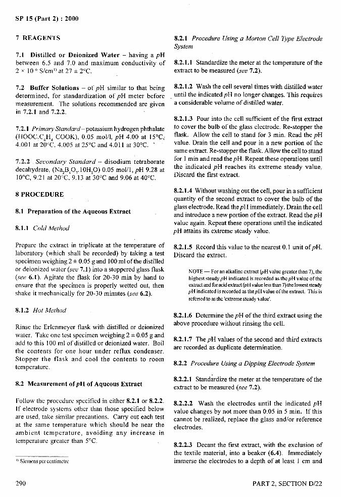
SP 15 (Part 2) :2000-—
7 REAGENTS 8.2.1 Procedure Using a Morton Cell Type ElectrodeSystem
7.1 Distilled or Deionized Water – having a pH
between 6.5 and 7.0 and maximum conductivity of 8.2.1.1 Standardize the meter at the temperature of the2 x 10< S/cm’) at 27 + 2“C. extract to be measured (see 7.2).
7.2 Buffer Solutions – of pH similar to that beingdetermined, for standardization of pH meter beforemeasurement. The solutions recommended are givenin 7.2.1 and 7.2.2.
7.2.1 Primary Standard- potassium hydrogen phthalate
(HOOC.C,H, COOK), 0.05 mol/1, pH 4.00 at 15“C,4.001 at 20”C, 4.005 at 25°C and 4.011 at 30°C. ‘
7.2.2 Secondary Standard – disodium tetraboratedecahydrate, (Na2B,0,. 10H,O) 0.05 mol/1, pH 9.28 at10°C, 9.21 at 20°C, 9.13 at 30”C and 9.06 at 40°C.
8.2.1.2 Wash the cell several times with distilled wateruntil the indicated pH no longer changes. This requiresa considerable volume of distilled water.
8.2.1.3 Pour into the cell sufficient of the first extractto cover the bulb of the glass electrode. Re-stopper theflask. Allow the cell to stand for 3 min. Read the pHvalue. Drain the cell and pour in a new portion of thesame extract. Re-stopper the flask. Allow the cell to standfor 1 min and read the pH. Repeat these operations untilthe indicated pH reaches its extreme steady value.Discard the first extract.
8 PROCEDURE8.2.1.4 Without washing out the cell, pour in a sufficientquantity of the second extract to cover the bulb of the
8.1 Preparation of the Aqueous Extractglass electrode. Read thepH immediately. Drain the celland introduce a new portion of the extract. Read the pHvalue again. Repeat these operations until the indicated
8.1.1 Cold Method pH attains its extreme steady value.
Prepare the extract in triplicate at the temperature oflaboratory (which shall be recorded) by taking a testspecimen weighing 2 + 0.05 g and 100 ml of the distilledor deionized water (see 7.1) into a stoppered glass flask(see 6.1). Agitate the flask for 20-30 min by hand toensure that the specimen is properly wetted out, thenshake it mechanically for 20-30 minutes (see 6.2).
8.1.2 Hot Method
Rinse the Erlenmeyer flask with distilled or deionizedwater. Take one test specimen weighing 2 + 0.05 g and
add to this 100 ml of distilled or deionized water. Boilthe contents for one hour under reflux condenser.Stopper the flask and cool the contents to roomtemperature.
8.2.1.5 Record this value to the nearest 0.1 unit ofpH.Discard the extract.
NOTE— For an alkaline extract (pH value greater than 7), thehighest steadypH indicated is recorded as thepH value of theextractandforacidextract(pHvahrelessthan 7) the lowest steady
. -. -
pH indicated is recorded as thepH value of the extract. This is t
referredto asthe ‘extremesteady value’.$
8.2.1.6 Determine the pH of the third extract using theabove procedure without rinsing the cell.
8.2.1.7 The pH values of the second and third extractsare recorded as duplicate determination.
8.2.2 Procedure Using a Dipping Electrode System
8.2 Measurement ofpH of Aqueous Extract8.2.2.1 Standardize the meter at the temperature of theextract to be measured (see 7.2).
Follow the procedure specified in either 8.2.1 or 8.2.2. 8.2.2.2 Wash the electrodes until the indicated pH[f electrode systems other than those specified below value changes by not more than 0.05 in 5 min. If thisare used, take similar precautions. Carry out each test cannot be realized, replace the glass and/or referenceat the same temperature which should be near the electrodes.ambient temperature, avoiding any increase intemperature greater than 5“C.
8.2.2.3 Decant the first extract, with the exclusion ofthe textile material, into a beaker (6.4). Immediately
]1Siemens per centimetre, immerse the electrodes to a depth of at least 1 cm and
290 PART 2, SECTION D/22
,*—__
stir very gently with a glass rod until the pH attains its
extreme steady value (see Note under 8.2.1.5).
8.2.2.4 Decant the second extract into a beaker.Transfer the electrodes, without washing, into thesecond beaker, lowering them gently to a depth of atleast 1 cm and allow to stand without stirringuntil the pH attains its extreme steady value. Recordthis value to the nearest 0.1 unit of pH (see Noteunder 8.2.1.5).
8.2.2.5 Decant the third extract in another beaker andtransfer the electrodes to this beaker, again withoutwashing. Determine the pH value as described above.
8.2.2.6 The pH values of the second and third extractsare recorded as duplicate determinations.
9 CALCULATION AND EXPRESSION OFRESULTS
9.1 Give the values obtained for the second and thirdextracts as ‘first and second measurements’.
9.2 Calculate their mean to the nearest 0.05 unit ofpH.
10 INDEX OF DIFFERENCE
10.1 If the value of the pH measured is less than 3 or
greater than 9 determine the index of difference asfollows:
SP 15 (Part 2) :2000
a) Introduce 10 ml of the prepared aqueous extractinto a beaker (6.4) and add 90 ml of distilled ordeionized water (7.1 ).
b) Measure the pH of the solution to 0.1 unit of
pH following the procedures specified in 8.2.1
or 8.2.2.
c) The difference between the pH of the aqueous
extract prepared as in 8.1 and that of the dilution
to 1/1O is the index of difference.
10.2 This index of difference, which should never be
greater than unity, is especially high when the textile
contains strong acids or strong bases and these are not
buffered by weak acids or weak bases.
11 TEST REPORT
The test report shall include the following” information:
a)
b)
c)
d)
e)
o
!3)
h)
Reference to this metho~
Hot method or cold method;
Type of electrodes used;
The pH of the distilled water used;
The temperature of the laboratory;
The results obtained, expressed in the form
indicated in 9;
If necessary, the index of difference (see 10);
and
Any factor likely to have an effect on the results,
including any resistance to wetting out of the
specimen.
.
7...---!,
PART 2, SECTION D/22
/
291
II
~’I 1,
SP 15 (Part 2) :2000 ..—
DETERMINATION OF VISCOSITY
(OR FLUIDITY) OF SOLUTIONS OF COTTONAND REGENERATED CELLULOSIC MAN-MADE
FIBRES IN CUPRAMMONIUM HYDROXIDE
(Source : IS 244: 1984)
Viscosity of solutions of cellulose in cuprammonium hydroxide is of proven importance in some major industries.For instance, viscosity of such solutions affords a means of control of bleaching and other chemical operations towhich cellulose textiles, such as cotton, linen and rayon, are put through. Manufacturers of cellulose, paper, pulp,explosives, celluloids and lacquers also use this characteristic of cellulose solutions in the control of manufacturingprocesses.
Viscosity of solutions of cotton and regenerated cellulose in cuprammonium hydroxide has a close correlation withthe tensile strength of the fibres. For instance, very large changes at the high end of the viscosity scales areaccompanied by changes in the tensile strength of the cotton and rayon tibres which are too small to be capable ofdirect experimental detection. The absolute viscosity of a solution of a slightly scoured cotton, containing 0.5 g ofcellulose per 100 ml, is about 1 poise. But more vigorous scouring treatment may reduce this to 0.2 poise withoutseriously affecting the quality of the material. A fiuther fall of viscosity from 0.2 to 0.05 poise is accompanied,however, by a loss of 20 to 30 percent in tensile strength. Changes in viscosity of the same order but at differentparts of the scale have, therefore, a different technical significance; this is best brought out when the rate of flow isexpressed in terms of fluidity. It has been shown that, when fluidity is plotted against the percentage loss ofstrength produced by chemical action on cotton, a curve is obtained which approximates more closely to a straightline than that given by other methods of expression.
While testing mixtures of cellulosic fibres, it is more appropriate to estimate the fluidity of the cotton componentonly and therefore, only methods for determination of the fluidity of the cotton component are given. Since themajority of the mixtures are prepared before any treatment is applied which is likely to affect the fluidity, it can beassumed that any increase in fluidity of cotton com~onent reflects an increase in the fluidity of the other component,although these changes may not be proportional.
Three basic methods for calculating test specimen size and test results are given, the first dealing with pure tibre,the second and the third dealing with mixtures of cotton with cellulosic man-made fibres.
Difficulties in working with such cupramonium solutions are many. “Firstly it is necessary to exclude air from anylengthy contact with the solutions, as oxygen causes a marked decrease in viscosity. Hence, the solutions are madein the viscometer itself. Secondly, sometime even carefi.dly purified cotton (of consequent high viscosity) and somecommercially bleached cotton yarns or cloth give turbid solutions. This is avoided if the nitrous acid content of thesolutions is kept below 0.5 g/1 and also if the cotton is freed from extraneous matter before being dissolved.Thirdly, solutions of cotton in cuprammonium differ from truly viscous liquids. The apparent fluidity of suchsolutions consequently varies with the nature and dimensions of the viscometer. This abnormality, which appliesparticularly to cotton of high viscosity or low fluidity (that is, normal cotton) and which rapidly becomes lessaccentuated as the severity of treatment of cotton is increased, may be neglected.
1 SCOPE
It prescribes a method for determination of viscosity (orfludidity) of solutions of cotton, regenerated cellulosicfibres and blends of cotton with regenerated cellulosicfibres in cuprammonium hydroxide.
2 TERMINOLOGY
For the purpose of thisdefinitions shall apply.
292
standard, the following
2.1 Fluidity
Itis reciprocal of viscosity of the solution and isexpressed in reciprocal poises.
2.1.1 Fluidity of Cotton
Fluidity of cuprammonium hydroxide solutioncontaining 0.5 g of bone-dry cotton per 100 ml ofsolution at 20°C.
PART 2, SECTION D/23
J’ “
).,..
II1?
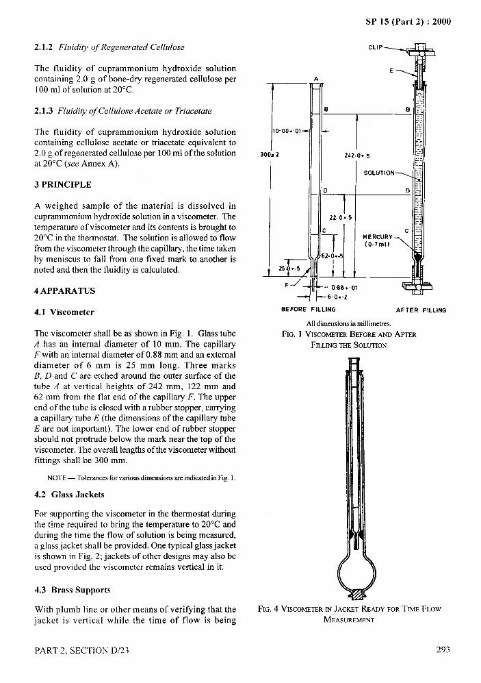
SP 15 (Part 2) :2000
2.1.2 Fluidity of Regenerated Cellulose
The fluidity of cuprammonium hydroxide solutioncontaining 2.0 g of bone-dry regenerated cellulose per100 ml of solution at 20”C.
2.1.3 Fluidity of Cellulose Acetate or Triacetate
The fluidity of cuprammonium hydroxide solutioncontaining cellulose acetate or triacetate equivalent to2.0 g of regenerated cellulose per 100 ml of the solutionat 20°C (see Annex A).
3 PRINCIPLE
A weighed sample of the material is dissolved incuprammonium hydroxide solution in a viscometer. Thetemperature of viscometer and its contents is brought to20”C in the thermostat. The solution is allowed to flowfrom the viscometer through the capillary, the time takenby meniscus to fall fi-om one fixed mark to another isnoted and then the fluidity is calculated.
4 APPARATUS
4.1 Viscometer
The viscometer shall be as shown in Fig. 1. Glass tubeA has an internal diameter of 10 mm. The capillaryF with an internal diameter of 0.88 mm and an externaldiameter of 6 mm is 25 mm long. Three marksB, D and C are etched around the outer surface of thetube A at vertical heights of 242 mm, 122 mm and62 mm from the flat end of the capillary F. The upperend of the tube is closed with a rubber stopper, carryinga capillary tube E (the dimensions of the capillary tubeE are not important). The lower end of rubber stoppershould not protrude below the mark near the top of theviscometer. The overall lengths of the viscometer withoutfittings shall be 300 mm.
NOTE — Tolerancesfor variousdimensionsare indicatedin Fig. 1.
4.2 Glass Jackets
For supporting the viscometer in the thermostat duringthe time required to bring the temperature to 20”C andduring the time the flow of solution is being measured,a glass jacket shall be provided. One typical glass jacketis shown in Fig. 2; jackets of other designs may also beused provided the viscometer remains vertical in it.
4.3 Brass Supports
With plumb line or other means of verifying that thejacket is vertical while the time of flow is being
I
CLIP
7
,;
E-..A
TIllalo. oo.. rl)--
‘ 1 k
1300s 2 242.0+.5 —-:-.
SOLUTION ;:.-_-
0 D Z:
..-.- --
22. 0+.5 --
I---
r ~ ---
IHI - - I&l
[1-.-----:,-----.---
~254~:+j1(07m~6.0+-2
BEFORE FILLING AFTER FILLING
—.+.-.,1
Alldimensionsin millimetres,
FIG. 1 VISCOME~R BEFORE ANDAFTER
FILLINGTHESOLUTION
%...
FIG. 4 VISCOMETERINJACKETREADY FORTIME FLOW
MEASUREMENT
PART 2, SECTION D/23
/
293
I
!

SP 15 (Part 2) :2000
measured. One suitable design is illustrated inFig. 3.
4.4 Blackened Glass Container – for cuprammoniumhydroxide solution.
4.5 A device for rotating the filled viscometer end-over-end at a speed not more than 4 rev/rein.
4.6 Glass Thermostat – with stirrer, capable of beingmaintained at 20 + 1.O°C or 20 + O.l °C (see 6.5).
4.7 Stop-Watch – graduated in seconds and fifth of asecond.
4.8 Steel Rod – approximately 1.6 mm in diameterand 300 mm long.
4.9 Strips of Black Cloth – to cover viscometer.
FIG. 3 BRASS SUPPORTS
5 CUPRAMMONIUM HYDROXIDE SOLUTION
5.1 The cuprammonium hydroxide solution used shallhave the following composition:
Copper
Ammonia
‘Nitrous acid
5.1.1 The solution shall beuse as given in Annex B.
294
15+ o.1g/1
200 + 5 gll
less than 0.5 g/1
prepared and tested before
6 PROCEDURE
6.1 Remove all the non-cellidosic matter from the
material under examination as given in IS 9068:1979
‘Recommended methods for removal of non-fibrous
matter prior to quantitative analysis of fibre mixture’
(see Note) and dry. If a blend is to be tested, determine
the composition using the appropriate method as
given in IS 1564:1962 ‘Method for quantitative
Chemical analysis of binary mixture of cellulose
triacetate and certain after figures (#h? revision)’,
IS 1889 (Parts 1 and 2):1976 ‘Method for quantitative
chemical analysis of binary mixture of regenerated
cellulose tibre and cotton - Sodium zincate and cadoxen
solvent methods’, and IS 2176:1962 ‘Textiles- Binary
mixtures of cellulose acetate and certain other fibres —
Methods for quantitative chemical analysis (#2rst
revision)’, before determining the fluidity using a fi-esh
sample. Condition the sample in standard atmosphere
at 27 + 2“C’ temperature and 65 + 2 percent relative
humidity (see also IS 6359:1971 ‘Method of
conditioning of textiles’ given in Section B-1/1). Cut
yarns or loose fibres into lengths of 2 mm such that
specimen includes both warp and weft yarns.
NOTE — Some of the methods specified in IS 9068:1979‘Recommendedmethodsfor removal of non-fibrousmatter prior toquantitative analysis of fibre mixture’may degrade cellulose andtherefore, correct fluidity values cannot be obtained when thesemethodsare usedto removeaddedmatter.
6.2 Mass of Specimen
Calculate the mass of the specimen of cotton orregenerated cellulose required, by the formula givenin C-3.
6.2.1 Cotton
Assuming the moisture regain of 6.5 percent of pure or
slightly modified cotton, weigh to the nearest milligram
the required quantity of material as obtained
in 6.1 depending on the volume of the viscometer used
(see Annex C) to give, on bone-dry basis, 0.500+0.001
percent solution. In case of mercerized cotton, weigh
the required quantity of material as in 6.1 assuming
moisture regain of 8.5 percent to give 0.500+ 0.001
percent solution on bone-dry basis depending on volume
of the viscometer used (see Annex C).
6.2.2 Regenerated Cellulose or Cellulosic Man-made
Fibres
PART 2, SECTION D/23
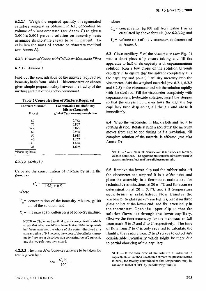
. . -—SP 15 (Part 2) :2000
6.2.2.1 Weigh the required quantity of regeneratedcellulose material as obtained in 6.1, depending onvolume of viscometer used (see Annex C) to give a
2.000 + 0.001 percent solution on bone-dry basisassuming its moisture regain to be 11 percent. Tocalculate the mass of acetate or triacetate required(see Annex A).
6.2.3 Mixture of Cotton with Cellulosic Man-made Fibre
6.2.3.1 Method 1
fFind out the concentration of the mixture required onbone-dry basis from Table 1. This concentration chosengives simple proportionality between the fludity of the
mixture and that of the cotton component.
Table 1 Concentration of Mixture Required
Cotton in Mixturel) Concentration 100 (Bone-DryMixture Required)
Percent g/ml of Cuprammonium solution
80 0.76275 0.807
66.7 0.87560 0.94850 1.08840 1.267
33.3 1.42425 1.649
!}Bone-dry basis.
6.2.3.2 Method 2
Calculate the concentration of mixture by using the
formula:1
“n= 1.5RC+ 0.5
where
C.= concentration of the bone-dry mixture, gll 00ml of the solution; and
RC= the mass (g) of cotton per g of bone-dry mixture.
NOTE — The second method gives a concentration whichequals that which would have been obtained if the componentshad been separate, the whole of the cotton dissolved at aconcentration of O.5percent, the whole of the celhdosic man-made fibre being dissolved at a concentration of2 percent,and the two solutions then mixed.
6.2.3.3 The mass M of bone-dry mixture to be taken fortest is given by :
~= cm V.
100
PART 2, SECTION D/23
where _——.
Cm= concentration (g/l 00 ml) from Table 1 or ascalculated by above formula (see 6.2.3.2); and
&-a~ = volume (ml) of the viscometer, as determined ‘q
in Annex C.
6.3 Close capillary F of the viscometer (see Fig. 1)
with a short piece of pressure tubing and fill the
apparatus to half of its capacity with cuprammonium
solution. Run a few drops of the solution through
capillary F to ensure that the solvent completely tills
the capillary and pour 0.7 ml dry mercury into the
viscometer. Add the weighed material (see 6.2.1, 6.2.2
and 6.2.3) in the viscometer and stir the solution rapidly
with the steel rod. Fill the viscometer completely with
cuprammonium hydroxide solution, insert the stopper
so that the excess liquid overflows through the top
capillary tube displacing all the air and close it
immediately.
6.4 Wrap the viscometer in black cloth and fix it to
rotating device. Rotate at such a speed that the mercury
moves from end to end during half a revolution, till
complete solution of the material is effected (see also
Annex D).
NOTE — A maximum rate of 4 revlmin is suitable even for veryviscous solutions. The agitation thus produced is sufficient tocause complete solution of the cellulose overnight.
6.5 Remove the lower c}ip and the rubber tube off ~..%
the viscometer and suspend it in a wider tube, and .
place the assembly in a thermostat maintained for
technical determinations, at 20 + 1‘C and for accurate
determination at 20 + 0.1 “C and till temperature
equilibrium is established. Now transfer the
viscometer to glass jacket (see Fig. 2), rest it on three
glass points at the lower end, and fix it vertically in
the thermostat. Open the upper clip so that the
solution flows out through the lower capillary.
Observe the time necessary for the meniscus to fall
from mark B to D and B to C respectively. The time
of flow from B to C is only required to calculate the
fluidity, the reading from B to D serves to detect any
considerable irregularity which might be there due ,,.
to partial chocking of the capillary. ~
NOTE— If the flow time of the solution of cellulose incuprarnmoniumsolution is measured at room temperature insteadat 20°C, the fluidity determined at that temperature may be
I
converted to that at 20°C by the following formula:
295
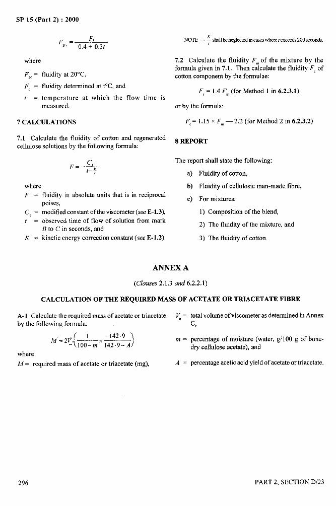
#-
I
Ij
Sk’ 15 (k’art 2) : zuuu
F,. = “0.4 + o.3t
where
F,, = fluidity at 20”C,
F, = fluidity determined at t°C, and
t = temperature at which the flow time ismeasured.
7 CALCULATIONS
7.1 Calculate the fluidity of cotton and regeneratedcellulose solutions by the following formula:
F= +t
whereF.
c, =
t=
K.
fluidity in absolute units that is in reciprocalpoises,
modified constant of the viscometer (see E-1.3),
observed time of flow of solution from markB to C in seconds, and
kinetic energy correction constant (see E-1.2),
NOTE — ~ shallbeneglectedincaseswheret exceeds200seeonds.
7.2 Calculate the fluidity F~ of the mixture by theformula given in 7.1. Then calculate the fluidity F=ofcotton component by the formulae:
F,= 1.4 F~ (for Method 1 in 6.2.3.1)
or by the formula:
F,= 1.15 x F~ — 2.2 (for Method 2 in 6.2.3.2)
8 REPORT
The report shall state the following:
a) Fluidity of cotton,
b) Fluidity of cellulosic man-made fibre,
c) For mixtures:
1) Composition of the blend,
2) The fluidity of the mixture, and
3) The fluidity of cotton.
ANNEX A
(Clauses 2.1.3 and 6.2.2.1)
CALCULATION OF THE REQUIRED MASS OF ACETATE OR TRIACETATE FIBRE
A-1 Calculate the required mass of acetate or triacetate ~=
by the following formula:
( 1 142.9M = 2170 —
- 100–m x142.9-A )m.
where
M= required mass of acetate or triacetate (mg), A=
296
total volume of viscometer as determined in Annexc,
percentage of moisture (water, g/100 g of bone-dry cellulose acetate), and
percentage acetic acid yield of acetate or triacetate.
PART 2. SECTION D/23
! ..
\
!Y
II I
i’!
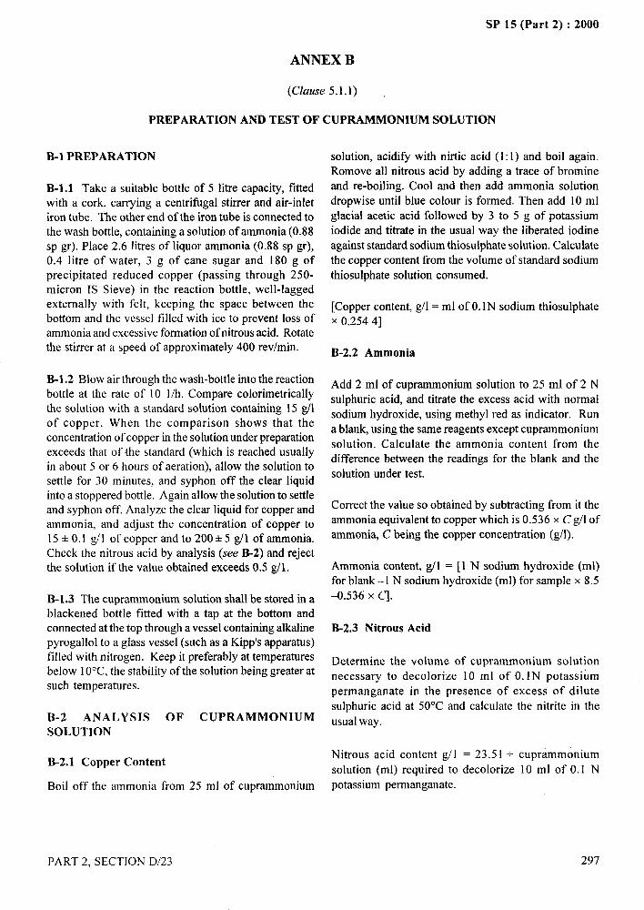
SP 15 (Part 2) :2000
ANNEX B
(Clause 5.1.1)
PREPARATION AND TEST OF CUPRAMMONIUM SOLUTION
._. —-.-
B-1 PREPARATION
B-1.l Take a suitable bottle of 5 litre capacity, fittedwith a cork, carrying a centrifugal stirrer and air-inletiron tube. The other end of the iron tube is connected tothe wash bottle, containing a solution of ammonia (0.88sp gr). Place 2.6 litres of liquor ammonia (0.88 sp gr),0.4 litre of water, 3 g of cane sugar and 180 g ofprecipitated reduced copper (passing through 250-micron IS Sieve) in the reaction bottle, well-laggedexternally with felt, keeping the space between thebottom and the vessel filled with ice to prevent loss ofammonia and excessive formation of nitrous acid. Rotatethe stirrer at a speed of approximately 400 rev/rein.
B-1.2 Blow air through the wash-bottle into the reaction
bottle at the rate of 10 1/h. Compare calorimetricallythe solution with a standard solution containing 15 gllof copper. When the comparison shows that theconcentration of copper in the solution under preparationexceeds that of the standard (which is reached usuallyin about 5 or 6 hours of aeration), allow the solution tosettle for 30 minutes, and syphon off the clear liquidinto a stoppered bottle. Again allow the solution to settleand syphon off. Analyze the clear liquid for copper andammonia, and adjust the concentration of copper to15 + 0.1 g/] of copper and to 200+5 g/1 of ammonia.
Check the nitrous acid by analysis (see B-2) and rejectthe solution if the value obtained exceeds 0.5 g/1.
B-1.3 The cuprammonium solution shall be stored in ablackened bottle fitted with a tap @ the bottom andconnected at the top through a vessel containing alkalinepyrogallol to a glass vessel (such as a Kipp’s apparatus)filled with nitrogen. Keep it preferably at temperaturesbelow 10°C, the stability of the solution being greater atsuch temperatures.
B-2 ANALYSIS OF CUPRAMMONIUMSOLUTION
B-2.1 Copper Content
Boil off the ammonia from 25 ml of cuprammonium
solution, acidify with nirtic acid (1:1) and boil again.
Remove all nitrous acid by adding a trace of bromine
and re-boiling. Cool and then add ammonia solution
dropwise until blue colour is formed. Then add 10 ml
glacial acetic acid followed by 3 to 5 g of potassium
iodide and titrate in the usual way the liberated iodine
against standard sodium thiosulphate solution. Calculatethe copper content fi-om the volume of standard sodium
thiosulphate solution consumed.
[Copper content, g/1 = ml of O.lN sodium thiosulphate
X 0.254 4]
B-2.2 Ammonia
Add 2 ml of cuprammonium solution to 25 ml of 2 N
sulphuric acid, and titrate the excess acid with normal
sodium hydroxide, using methyl red as indicator. Run
a blank, using the same reagents except cuprammonium
solution. Calculate the ammonia content from thedifference between the readings for the blank and the
solution under test.
Correct the value so obtained by subtracting from it theammonia equivalent to copper which is 0.536 x C #l of
ammonia, C being the copper concentration (g/l). $,.,,>
Ammonia content, #l = [1 N sodium hydroxide (ml)
for blank –1 N sodium hydroxide (ml) for sample x 8.5
-0.536 X q.
B-2.3 Nitrous Acid
Determine the volume of cuprammonium solution
necessary to decolonize 10 ml of O. lN potassium
permanganate in the presence of excess of dilute
sulphuric acid at 50”C and calculate the nitrite in the
usual way.
Nitrous acid content g/1 = 23.51 + cuprammonium
solution (ml) required to decolonize 10 ml of 0.1 N
potassium permanganate.
PART 2, SECTION D/23 297
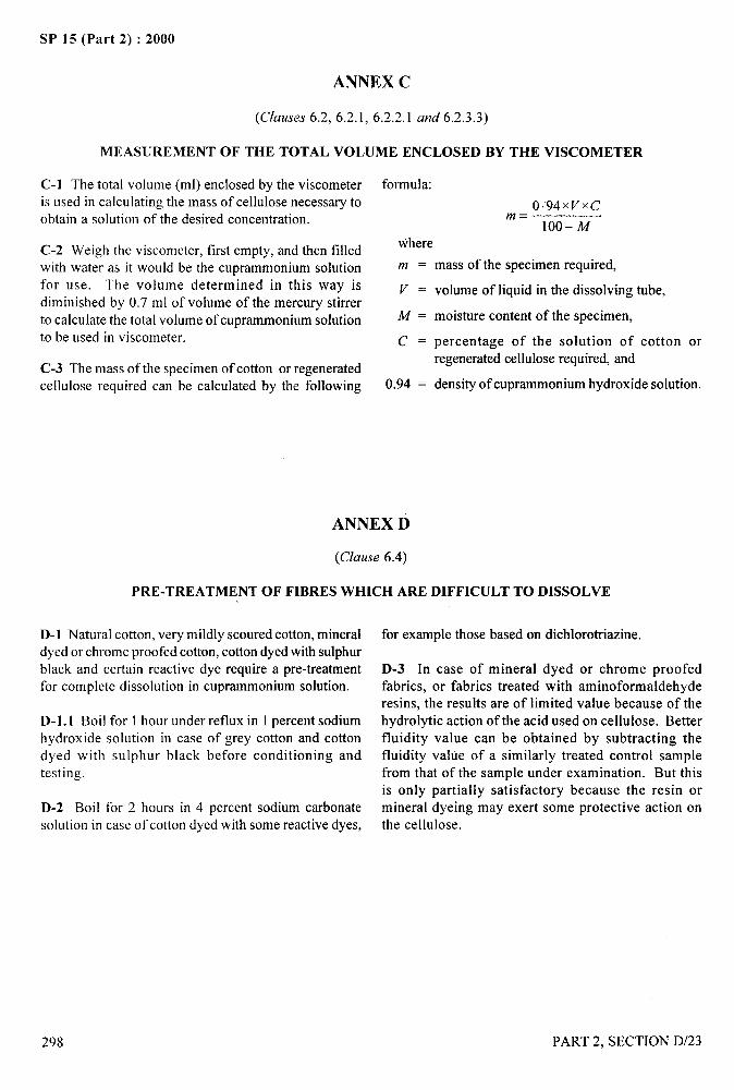
.* 4’.—
SP 15 (Part 2) :2000
ANNEX C
(Clauses 6.2,6 .2.1,6.2.2.1 and 6.2.3.3)
MEASUREMENT OF THE TOTAL VOLUME ENCLOSED BY THE VISCOMETER
C-1 The total volume (ml) enclosed by the viscometeris used in calculating the mass of cellulose necessary toobtain a solution of the desired concentration.
C-2 Weigh the viscometer, first empty, and then tilledwith water as it would be the cuprammonium solutionfor use. The volume determined in this way isdiminished by 0.7 ml of volume of the mercury stirrerto calculate the total volume of cuprammonium solution
to be used in viscometer.
C-3 The mass of the specimen of cotton or regeneratedcellulose required can be calculated by the following
formula:
094~v~cm=
100- M
where
m = mass of the specimen required,
V = volume of liquid in the dissolving tube,
M = moisture content of the specimen,
C = percentage of the solution of cotton orregenerated cellulose required, and
0.94 = density of cuprammonium hydroxide solution.
ANNEX D
(Clause 6.4)
PRE-TREATMENT OF FIBRES WHICH ARE DIFFICULT TO DISSOLVE
D-1 Natural cotton, very mildly scoured cotton, mineraldyed or chrome proofed cotton, cotton dyed with sulphurblack and certain reactive dye require a pre-treatmentfor complete dissolution in cuprammonium solution.
D-1. 1 Boil for 1 hour under reflux in 1 percent sodiumhydroxide solution in case of grey cotton and cottondyed with sulphur black before conditioning andtesting.
D-2 Boil for 2 hours in 4 percent sodium carbonatesolution in case of cotton dyed with some reactive dyes,
for example those based on dichlorotriazine.
D-3 In case of mineral dyed or chrome proofedfabrics, or fabrics treated with aminoformaldehyderesins, the results are of limited value because of thehydrolytic action of the acid used on cellulose. Betterfluidity value can be obtained by subtracting thefluidity value of a similarly treated control samplefrom that of the sample under examination. But thisis only partially satisfactory because the resin ormineral dyeing may exert some protective action onthe cellulose.
_._;-,
298
,!/i
PART 2, SECTION D/23
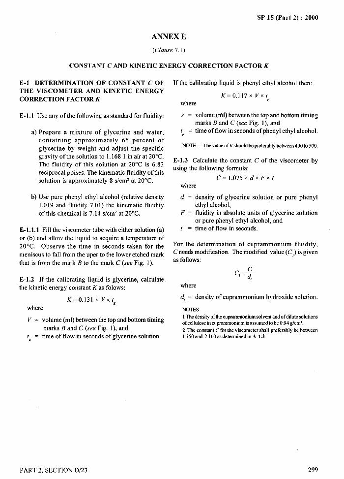
SP 15 (Part 2) :2000
ANNEX E
(Clause 7.1)
,~.—-. _
. .--.
CONSTANT C AND KINETIC ENERGY CORRECTION FACTOR K
E-1 DETERMINATION OF CONSTANT C OF If the calibrating liquid is phenyl ethyl alcohol then:
THE VISCOMETER AND KINETIC ENERGY
CORRECTION FACTOR KK= 0.117x Vxt 1)
where
E-1.l Use any of the following as standard for fluidity: V = volume (n’d) between the top and bottom timingmarks B and C (see Fig. 1), and
a) Prepare a mixture of glycerine and water, t,,= time of flow in seconds of phenyl ethyl alcohol.
containing approximately 65 percent of
glycerine by weight and adjust the specificNOTE— The value of Kshould be preferablybetween 400 to 500.
gravity of the solution to 1.1681 in air at 20°C.
The fluidity of this solution at 20”C is 6.83E-1.3 Calculate the constant C of the viscometer byusing the following formula:
reciprocal poises. The kinematic fluidity of this
solution is approximately 8 s/cm2 at 20”C. C=l.075xd XFxtwhere
b) Use pure phenyl ethyl alcohol (relative density
1.019 and fluidity 7.01) the kinematic fluidity
of this chemical is 7.14 s/cm2 at 20”C.
E-1.l.l Fill the viscometer tube with either solution (a)
or (b) and allow the liquid to acquire a temperature of
20”C. Observe the time in seconds taken for the
meniscus to fall from the uper to the lower etched mark
that is from the mark B to the mark C (see Fig. 1).
E-1.2 If the calibrating liquid is glycerine, calculate
the kinetic energy constant K as folows:
K= O.131XVxt xwhere
V = volume (ml) between the top and bottom timing
marks B and C (see Fig. 1), and
tg= time of flow in seconds of glycerine solution.
d = density of glycerine solution or pure phenyl
ethyl alcohol,F = fluidity in absolute units of glycerine solution
or pure phenyl ethyl alcohol, andt = time of flow in seconds.
For the determination of cuprammonium fluidity,
C needs modification. The modified value (Cl) is givenas follows:
c,= $-,where
dC = density of cuprammonium hydroxide solution.
NOTES1 The densityof the cuprammoniumsolvent and of dilute solutionsof cellulose in cuprammoniumis assumed to be 0.94 g/cm~.2 The constant C forthe viscometershallpreferablybe between1750 and 2100 as determined in A-1.3.
,!,\
PART 2, SECTION D/23
/
299
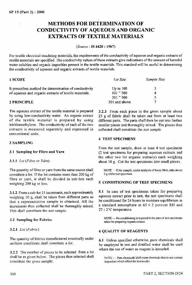
4t,
SP 15 (Part 2) :2000
METHODS FOR DETERMINATION OFCONDUCTIVITY OF AQUEOUS AND ORGANIC
EXTRACTS OF TEXTILE MATERIALS
(Source : IS 4420: 1967)
For textile electrical-insulating materials, the requirements of the conductivity of aqueous and organic extracts oftextile materials are specified. The conductivity values of these extracts give indications of the amount of harmfulwater solubles and organic impurities present in the textile materials. This standard will be useful in determiningthe conductivity of aqueous and organic extracts of textile materials.
1 SCOPE
It prescribes method for determination of conductivityof aqueous and organic extracts of textile materials.
2 PRINCIPLE
The aqueous extract of the textile material is prepared
by using low-conductivity water. An organic extractof the textile material is prepared by usingtrichloroethylene, The conductivity of each of the twoextracts is measured separately and expressed inconventional units.
3 SAMPLING
3.1 Sampling for Fibre and
3.1.1 Lot (Fibre or Yahz)
Yarn
The quantity of fibre or yarn from the same source shall
constitute a lot. If the lot contains more than 200 kg offibre or yarn, it shall be divided in sub-lots eachweighing 200 kg or less.
3.1.2 From a sub-lot 15 increments, each approximatelyweighing 10 g, shall be taken from different parts sothat a representative sample is obtained. All theincrements thus collected shall be thoroughly mixed.This shall constitute the test sample.
3.2 Sampling for Fabrics
3.2.1 Lot (Fabric)
The quantity of fabrics manufactured essentially underuniform conditions shall constitute a lot.
3.2.2 The number of pieces to be selected from a lotshall be as given below. The pieces thus selected shallconstitute the gross sample:
300
Lot Size Sample Size
up to 100 3
101 “ 300 4301 “ 500 5
501 and above 7
3.2.3 From each piece in the gross sample about25 g of fabric shall be taken out from at least twodifferent parts. The parts shall then be cut into furthersmaller pieces and thoroughly mixed. The pieces thuscollected shall constitute the test sample.
4 TEST SPECIMENS
From the test sample, draw at least 4 test specimens(2 test specimens for preparing aqueous extracts andthe other two for organic extracts) each weighingabout 10 g. Cut the test specimens into small pieces.
NOTE—If the sample,underanalysis of loose fibre, take about5 g of the test specimen.
5 CONDITIONING OF TEST SPECIMENS
5.1 In case of test specimens taken for preparingaqueous extract prior to test, the test specimens shallbe conditioned for 24 hours to moisture equilibrium ina standard atmosphere at 65 + 2 percent RH and27+ 2°C temperature.
NOTE—No conditioning is required in the case of test specimenstaken forpreparingorganicextract.
6 QUALITY OF REAGENTS
6.1 Unless specified otherwise, pure chemicals shallbe employed in test and distilled water shall be usedwhere the use of water as reagent is intended.
NOTE— ‘Purechemicals’shall mean chemicalsthat do not containimpurities which affect the test results.
PART 2, SECTION D/24
—-1---,
/
1 I
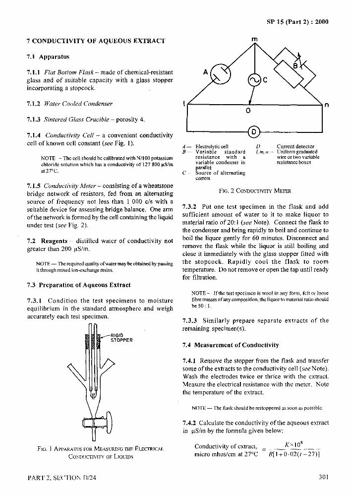
7 CONDUCTIVITY OF AQUEOUS EXTRACT
7.1 Apparatus
7.1.1 Flut Bottom Flask --made ofchemical-resistantglass and of suitable capacity with a glass stopperincorporating a stopcock.
7.1.2 Watercooled Condenser
7.1.3 Sintered Glass Crucible –porosity4.
7.1.4 Conductivity Cell – a convenient conductivity
cell of known cell constant (see Fig. 1).
NOTE— The cell should be calibrated with N/l 00 potassiumchloride solution which has a conductivity of 127800 pS/mat 27°C.
7.1.5 Conductivity Meter – consisting of a wheatstone
bridge network of resistors, fed from an alternatingsource of frequency not less than 1 000 CIS with asuitable device for assessing bridge balance. One armof the network is formed by the cell containing the liquidunder test (see Fig. 2).
7.2 Reagents – distilled water of conductivity notgreater than 200 pS/m.
NOTE — The requiredqualityof water maybe obtainedby passingit throughmixed ion-exchangeresins.
7.3 Preparation of Aqueous Extract
7.3.1 Condition the test specimens to moistureequilibrium in the standard atmosphere and weighaccurately each test specimen.
FIG. 1 APPARATIJSFORMEASURINGTHEELECTRICAL
CONDIJCHVITYOF LIQUJDS
SP 15 (Part 2) :2000
m
n
I o II I
A — Electrolytic cell D — Current detectorB— Variable standard /, m,n — Uniform graduated
resistance with a wire or two variablevariable condenser in resistance boxesparallel
C— Source of alternatingcurrent
FIG. 2 CONDUCTIVITYMETER
7.3.2 Put one test specimen in the flask and addsufficient amount of water to it to make liquor tomaterial ratio of 20:1 (see Note). Connect the flask tothe condenser and bring rapidly to boil and continue toboil the liquor gently for 60 minutes. Disconnect andremove the flask while the liquor is still boiling andclose it immediately with the glass stopper fitted withthe stopcock. Rapidly cool the flask to roomtemperature. Do not remove or open the tap until readyfor filtration.
NOTE— If the test specimenis wool in any form, felt or loosetibre massesof artycomposition, the liquor to material ratio shouldbe50:l.
7.3.3 Similarly prepare separate extracts of theremaining specimen(s).
7.4 Measurement of Conductivity
7.4.1 Remove the stopper from the flask and transfersome of the extracts to the conductivity cell (see Note).Wash the electrodes twice or thrice with the extract.Measure the electrical resistance with the meter. Notethe temperature of the extract.
NOTE — The flask should be restoppered as soon as possible
7.4,2 Calculate the conductivity of the aqueous extractin pS/m by the formula given below:
Conductivity of extract, = KX108
micro mhos/cm at 27°C R[l+O.02(t -27)]
PART 2. SECTION D/24 301
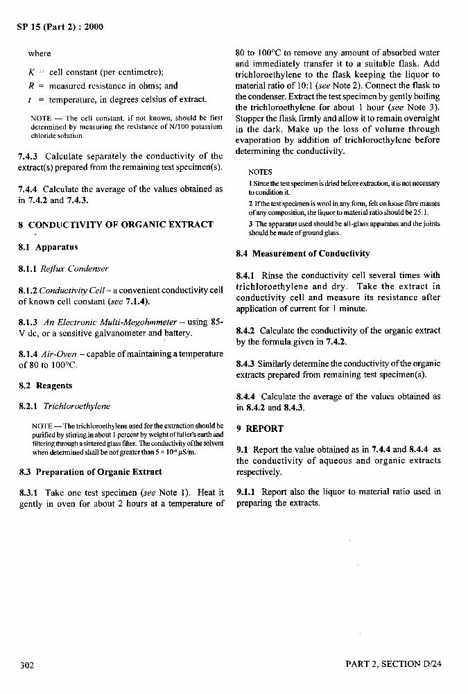
..—SP 15 (Part 2) :2000
where
K = cell constant (per centimetre);
R = measured resistance in ohms; and
t = temperature, in degrees celsius of extract.
NOTE — The cell constant, if not known, should be firstdetermined by measuring the resistance of N/100 potassiumchloride solution.
7.4.3 Calculate separately the conductivity of theextract(s) prepared from the remaining test specimen(s).
7.4.4 Calculate the average of the values obtained asin 7.4.2 and 7.4.3.
8 CONDUCTIVITY OF ORGANIC EXTRACT
8.1 Apparatus
8.1.1 Rejlux Condenser
8.1.2 Conductivity Cell – a convenient conductivity cellof known cell constant (see 7.1.4).
8.1.3 An Electronic A4ulti-A4egohmmeter – using 85-V dc, or a sensitive galvanometers and battery.
8.1.4 Air-Oven – capable of maintaining a temperatureof 80 to 100”C.
8.2 Reagents
8.2.1 Trichloroethylene
NOTE— The trichloroethylene used for the extraction should bepurified by stirring inabout1percentbyweightoffuller’searthandfilteringthrougha sintercdglassfilter.Theconductivityofthesolventwhen determined shrdlbe not greater than 5 x 10⁴pS/m.
8.3 Preparation of Organic Extract
80 to 100”C to remove any amount of absorbed waterand immediately transfer it to a suitable flask. Addtrichloroethylene to the flask keeping the liquor tomaterial ratio of 10:1 (see Note 2). Connect the flask tothe condenser. Extract the test specimen by gently boilingthe trichloroethylene for about 1 hour (see Note 3).Stopper the flask firmly and allow it to remain overnightin the dark. Make up the loss of volume throughevaporation by addition of trichloroethylene beforedetermining the conductivity.
NOTES
1 Sincethe test specimenistiled beforeextraction,it isnot necessayto condhion it.
2 If the test specimeniswool in any form, felt on loose fibre massesof any composition, the liquor to material ratio should be 25:1.
3 Theapparatusused should be all-glass apparatus and the jointsshould be made of groundglass.
8.4 Measurement of Conductivity
8.4.1 Rinse the conductivity cell several times withtrichloroethylene and dry. Take the extract inconductivity cell and measure its resistance afterapplication of current for 1 minute.
8.4.2 Calculate the conductivity of the organic extractby the formula given in 7.4.2.
8.4.3 Similarly determine the conductivity of the organicextracts prepared from remaining test specimen(s).
8.4.4 Calculate the average of the values obtained asin 8.4.2 and 8.4.3.
j?,:
9 REPORT
9.1 Report the value obtained as in 7.4.4 and 8.4.4 asthe conductivity of aqueous and organic extracts
respectively.
8.3.1 Take one test specimen (see Note 1). Heat it 9.1.1 Report also the liquor to material ratio used in
gently in oven for about 2 hours at a temperature of preparing the extracts.
302 PART 2, SECTION D/24
CA.4
...-.SP 15 (Part 2) :2000
ESTIMATION OF MOISTURE, TOTAL SIZE OR FINISH, —+
ASH AND FATTY MATTER IN GREY AND ‘i
FINISHED COTTON TEXTILE MATERIALS~ -a,,$,....,,,
(Source : IS 199: 1989) !.7
The size used for spun textile yams may consist of an adhesive, a lubricant, an antiseptic, or hydroscopic and
weighting materials. The adhesive is generally starch or soluble starch, but certain other carbohydrates, for example,
locust-bean gum, may be used alone or in mixtures with starch. The filling applied to fabric in finishing may
contain starch or dextrins with or without lubricant, and sometimes substantial proportion of weighting materials,
such as, china clay. The procedure described for estimation of starch is for use where test specimens of about 2 gare available; weighting materials, if present, are mainly removed along with the starch; the residual filling maybe
determined by ashing the desized specimen and, provided that the amount of residual mineral matter is small,
changes in its mass produced during ashing may be neglected. Unsized grey cotton loose mass in desizing process
and correction factor for the loss, has to be applied to the mass of the residual. The correction can be determinedif a specimen of the corresponding unsized yam is available. In the absence of such a specimen, the values for the
correction factor are assumed.
The oils, fats and waxes present in cotton maybe derived either from the cotton itself, or fi-om sizing and finishing
compositions added during manufacture. With some exceptions, these materials are removed by extraction with
suitable solvent. Dichloromethane (methylene chloride) has been found as suitable solvent for grey, scoured andbleached cotton if the extraction time does not exceed six hours, but it is unsuitable for dyed or printed materials
containing vat or azoic dyes or colorants for which the use of light petroleum (boiling range 40 to 60°C) is
recommended. The amount of natural fat or wax extracted from cotton materials by light petroleum is smaller
than that extracted by dichloromethane. The method prescribed does not purport to remove natural fats and waxes
completely. It gives a result that maybe low by about 0.2 g per 100 g of cotton or raw cotton, and low by less than
this amount on partly purified cotton but which is nevertheless, reproducible and serves to characterize the cotton
sufficiently for practical purposes.
1 SCOPE
1.1 It prescribes methods for estimation of (a) moisture,
(b) total size or finish, (c) ash, and (d) fatty matter ingrey and finished cotton textile materials.
1.2 The method prescribed for estimation of starch is
not applicable in cases where the starch has beeninsolubilized as in formaldehyde-containing finishes andis not intended for use in determining small amounts of
residual starch and fatty materials. The method
prescribed for determination of fatty matter is not
applicable to textile materials containing oxidized
unsatiated oils, waterproofing or softening preparations
derived from cetylpyridinium halides, rot-proofingagents, synthetic resins and other substances that wouldinterfere.
2 SAMPLING
2.1 Samples from the lot for testing shall be selected soas to be representative of the lot.
2.2 Samples drawn in accordance with the procedure
laid down in the material specification or as agreed to
between the buyer and the seller shall be held to be~
representative of the lot.
3 QUALITY OF REAGENTS
3.1 Unless specified otherwise, pure chemicals shall be
employed in the tests and distilled water shall be used where
the use of water as a reagent in intended.
NOTE— ‘Purechemicals’shall mean chemicals that do not containimpuritieswhich affectthe results of analysis.
4 ESTIMATION OF MOISTURE
4.1 Apparatus
4.1.1 Drying Oven, capable of maintaining atemperature of 105 + 3“C.
4.1.2 Weighing Balance
PART 2, SECTION D/25
/
303
I
I
1,1
1
.-—SP 15 (Part 2) :2000
4.2 Procedure
From the sample under test (see 2) draw at least 2 testspecimens each weighing approximately 3 g.
4.2.1 Take one test specimen drawn as in 4.2 and weighit accurately in a clean and dry tared weighing bottle.Place the weighing bottle containing the test specimenin the drying oven and dry the specimen at 105 + 3°C toconstant mass (see Note) and determine the oven-drymass of the test specimen.
NOTE— Themassmayusually be regarded as constant ifthe lossbetweentwo successiveweighing,taken at an intervalof20 minutes,does not exceed by 0.1 percent of the first of the two values.
4.2.2 Similarly test the other test specimen(s).
4.3 Calculations
Calculate the percentage of moisture content in the testspecimen by the following formula:
Moisture content, percent =M. 100a
where
a = original mass in g of the test specimen, andb = oven-dry mass in g of the test specimen.
4.3.1 Determine the mean of all values, obtained in 4.3and express it as moisture content of the material in thelot.
4.3.2 Corrected invoice mass of cotton textile materialsmay be calculated by the following formula:
~ = L(bxl.085)1 a
where
L, = corrected invoice mass in g of the lot,L = original mass in g of the lot,b = oven-dry mass in g of the test specimen, anda = original mass in g of the test specimen.
5 ESTIMATION OF TOTAL SIZE OR FINISH
5.1 Apparatus
5.1.1 Soxhlet Extractor
5.1.2 Drying Oven, capable of maintaining a
temperature of105 + 3“C.
5.1.3 Sintered Disc Filter Crucibles, of at least 60 mlcapacity, fitted with ground glass stopper or othersuitable cover.
304
5.1.4 Suitable Ignition Crucibles and Covers
5.1.5 MuJ71e Furnace, or other equipment for heatingcrucibles to a temperature of about 750”C.
5.2 Reagents
5.2.1 Dichloromethane (A4ethylene Chloride),redistilled.
5.2.2 Diastase or Other Suitable Desizing Enzyme
5.2.3 Sodium Chloride
5.2.4 Soap-Soda Solution
It shall contain 20 g of soap and 10 g of anhydroussodium carbonate per litre. The soap shall contain notmore than 5 percent moisture and shall comply withthe following composition on dry mass basis:
Free alkali (as NazCo~), Max 0.3 percent
Free alkali (as NaOH), Max 0.1 percent
Combined fatty acids 85 percent(as sodium salt), Min
Titre of mixed fatty acids 30”C
prepared from the soap, Max
Iodine value of fatty acids, Max 50
5.3 Procedure
From the sample under test (see 2), draw at least 2 test “specimens each weighing approximately 2 g.
5.3.1 If the sample under test is yarn, cut each testspecimen, into pieces of 15 cm long, from intoseparate bundles and tie each bundle loosely roundthe middle.
5.3.2 If the sample under test is fabric, trim each testspecimen parallel to the directions of warp and weft andpull out 5 threads all round to form a fringe.
5.3.3 Determine the moisture content of the sampleby the method prescribed in 4, using separate testspecimens. Weigh accurately one test specimen in atared crucible drawn as in 5.3 and calculate its oven-dry mass. Place the crucible with specimen in a Soxhletapparatus, with its rim above the level of the siphonand extract it in a Soxhlet extractor for one hour withdichloromethane adjusting the rate of boiling to at leastsix hot extractions per hour.
PART 2, SECTION D/25
I1’
,#.-.. —
SP 15 (Part 2) :2000
I
5.3.4 Remove the crucible from the extractor and allowthe solvent to evaporate. Attach the crucible to aBuchner flask and wash the extracted specimen bydrawing about 100 ml of water through it. Drain andremove the crucible and transfer the contents to a flaskof 150 ml capacity.
5.3.5 Treat the extracted specimen in the mannerprescribed in 5.3.5.1, 5.3.5.2, or 5.3.5.3 depending onthe type of the ingredients used in the size or finish.
5.3.5.1 In case it is known that the material is sized orfinished with a mixing containing starch but nottamarind kernel powder, add to the flask 50 ml ofbacterial diastase solution containing 5 g/1 of activediastase, 10 g/1 sodium chloride and 0.1 percent(m/m) of a non-ionic wetting agent at 70”C and at apH of 6.5 to 7.5 (see Note). Maintain this temperaturefor 30 min and shake the contents of the flask by anyconvenient means continuously or at intervals of 5 minduring this time. Decant the solution through the filtercrucible, add a fresh portion of bacterial diastasesolution at 70°C and at a pH of 6.5 to 7.5 to the flaskand repeat the desizing treatment. Take precaution toensure that the temperature in any part of the solutiondoes not exced 70°C or the limiting temperaturespecified by the manufacturer of enzyme. Afterdecanting the second portion of the solution, add waterto the flask and boil for 5 min. Finally transfer thedesized material to the crucible, drain and wash withthree successive 100 ml portions of hot water whilestirring the contents with a glass rod, and drain withsuction after each wash. If the washings are opalescentwith mineral filling, continue washing until they areclear.
NOTE— ThetemperatureandpH givenfor the desizing solutionare the optimum for bacterial diastase. Ifanyothertypeofdesizingenzymeis used, then the temperaturermdpHshouldbemodifiedtothat recommendedby the supplier. Asmanyenzymaticdesizingagentsslowlydeterioratein storage,careshouldbe takento seethatthe sample of desizing agent, at the time of tes~has still satisfactorydesizingeticiency.
5.3.5.2 In case it is known that the material is sized orfinished with a mixing containing tamarind kernelpowder but not starch, boil the specimen in the soap-soda solution (weighing 20 time the mass of thespecimen) for 45 minutes. Wash it thoroughly fust inhot water and then in cold water.
5.3.5.3 In case it is known that the material is sized orfinished with a mixing containing both starch andtamarind kernel powder or in case the ingredients usedin the size or finish are not known desize the specimen
PART 2, SECTION D/25
as prescribed in 5.3.5.1 and treat it further as prescribedin 5.3.5.2.
5.3.6 Dry the specimen treated as above (see 5.3.3to 5.3.5) in the drying-oven at 105 + 3°C to constantmass (see Note under 4.2.1) accurately.
5.3.7 Residual Mineral Filling
If the sample orginally contained a substantial amount
of insoluble mineral filling, for example, china clay,transfer the desized specimen to an ignition crucible,previously ignited with its lid at 750°C (see Note 3
under 6.2.1), cooled and its mass determined. Place the
open crucible at the front of the muffle furnace and burnoff the fibre while manipulating the crucible lid to
prevent the tibre ilom inflaming. Move the crucible tothe interior of the i%mace, replace the lid, and continue
the combustion at 750°C until no carbonaceous residue
remains. Cool and determine the mass of the crucibleand its content and calculate the mass of ash. Correct
the mass of the desized specimen by subtracting the mass
of the ash.
5.3.8 Similarly repeat the test with other test specimens.
5.4 Calculations
Calculate the percentage of total dry size or finishexpressed on the oven-dry mass of the unsized materialby the following formula:
x=a–kb—Xloo
kbwhere
x.
a=
k=
b=
c=
d=
total size or finish, percent by mass;
oven-dry mass (calculated) in g of the testspecimen containing the size or finish;
,-;, that is, the correction factor determined
experimentally (on unsized or blanks) foradjusting the value of b, due to loss of naturalconstituents sustained by the test specimen duringtreatment as prescribed in 5.3.3 and 5.3.4;
oven-dry mass in g of the test specimendetermined as in 5.3.6 or 5.3.7, if necessary;
oven-dry mass in g of unsized or unfinishedblanks; and
oven-dry mass in g of blank after treatment asprescribed in 5.3.3 to 5.3.7
305
I,, ~I I
SP 15 (Part 2) :2000
NOTE— Normallyk cannot be determined experimentally as acomparable unsized or unfinished control blank is usually notavailable,particularlyso in thecaseof fabric. In the absence of acontrol blank, k shall be taken as equal to 1.05 in the case of greyyarn and fabric; and equal to 1.00in the case of scoured bleached,dyed, mercerized and printed material. The prescribed vrduesofkfor unsized grey cotton material may vary from actual value,particularly if Indian cottons are involved. Therefore, some slightinaccuracymay be expectedwhen the prescribedvahresare used.
5.4.1 Determine the mean of all values as obtainedin 5.4.
5.4.2 Total size or finish of cotton textile materialexpressed as a percentage of
a) original mass of the material,b) conditioned mass of the material, andc) corrected invoice mass of the material, maybe
calculated by the following formula
x,=a–kb—Xloo
X=a–kb2 —X loo
a2
x= a–kbXloo
3 kbxl.ogs
where
J-, =
J’,=
x’=
a=
k=
b=
al =
al =
total size or finish as a percentage by mass ofthe original mass of the material,
total size or finish as a percentage by mass ofthe conditioned mass of the material,
total size or finish as a percentage by mass ofthe corrected invoice mass of the material,
oven-dry mass (calculated ) of the test specimencontaining the size or finish,
correction factor for b (see 5.4),
oven-dty mass of the test specimen determinedas in 5.3.5,
original mass in g of the test specimen, and
conditioned mass in g of the test specimen.
6 ESTIMATION OF ASH
6.1 Apparatus
6.1.1 Silica or Porcelain Crucible, of about 40 ml
capacity.
6.1.2
6.1.3
306
Mujjt?eFurnace, capable of being heated to 750°C.
Drying Oven, controlled at 105+ 3“C.
6.1.4 Weighing Bottle,
contain the crucible.of suitable size and shape to
6.1.5 Desiccator (vacuum Type), containing anhydrouscalcium chloride.
6.1.6 Pastille Press, One, suitable for making pastillesof 15 mm diameter.
6.2 Procedure
6.2.1 Compress a suitable mass of the material
(see Note 1) into pellets from 0.5 to 1.0 g each and
heat in an open, tared, weighing bottle at 105 + 3°C
overnight (see Note 2). Place the stopper in the bottle
and after cooling in a desiccator, determine the mass of
the bottle and its contents. Transfer the pellets to the
crucible which has previously been ignited, cooled in
desiccator and its mass accurately determined in the
weighing bottle. Burn the pellets cautiously at the tl-ont
of the open furnace, taking care to avoid draughts and
when the material has reached the glowing stage, move
the crucible towards the rear of the fimace, close the
front door, and complete ashing at about 750°C
(see Note 3). Transfer the dish after it has been allowed
to cool in the desiccator, to the weighing bottle and
finally determine its mass (see Note 3).
NOTES
1 The mass ofmaterial used is governedby the anticipated ash, forexample, for grey cottons a 5 g specimen is generalIy used; for awell-scouredor bleachedcottonmaterial,a 10g specimen is neededto give an amount of ash that can be determined with reasonableaccuracy.
2 For marrypurposes, the initial drying of the specimen maybeneglectedandan averagefigure assumedfor the moisture contentofthe fibre.
3 Certain metats can be lost under these conditions of heating.Mercury is lost readiIyand zinc is lost above450”C. Temperaturesin excess ofgenersd ashing temperature may occur locally in largespecimens and the general ashing temperature in such cases mayhaveto be considerablyreducedto avoid lossof certainmetals.Leadis atso lostunderthe specifiedconditionsof heating unless sulphateion ispresent.
4 Considerablelossin ashmayoccurdueto draught. It isptiiculadynecessaryto exercisecaution in openingthe desiccatorin which theashhasbeencooledsincea partialvacuum iscreatedduringcooling.The safest procedure is to press apiece of filter paper against theoutletwhilst cautiouslyopening the tap.
5 Silicaand porcelaincrucibles become etched during heating andcooling cycles over a prolonged period and it is recommended thatcruciblesshouldbe renewedfairly frequently.
6.2.2 Similarly repeat the test with at least one more
test specimen.
PART 2, SECTION D/25
‘,.,p.,

SP 15 (Part 2) :2000
6.3 Calculation
Calculate the percentage of ash by the following formula:
Ash content, percent = ~ x 100
where
a = mass in g of the residue (ash), andb = oven-dry mass (calculated) in g of the test
specimen.
6.3.1 Determine the mean of all values as obtainedin 6.3.
7 ESTIMATION OF FATTY MATTER
7.1 Apparatus
7.3.3 If the material contains size or finish based onstarch in which oil, fat or wax has been incorporated,treat the specimen in 0.4 N hydrochloric acid for 30minutes under reflux at the boil, rinse thoroughly inwater and dry at a temperature not exceeding 55“C.Place the specimen in a thimble in a Soxhlet extractor.Dry an extraction-flask at 95 to 100°C, cool in adesiccator and determing its mass. Assemble theapparatus and pour the solvent (see Note) slowly throughthe condenser until the siphon operates. Add a further10 to 20 ml of solvent. Heat the flask on a water-bath orelectric hot plate so that the solvent siphons at least sixtimes per hour for three hours, keeping the volume ofsolvent fairly constant by adding enougth of it to makeup for any loss due to evaporation.
NOTE — The choiceofsolvent should be as agreedto between thebuyer andthe seller.
7.1.1 Soxhlet Extractors, of capacity 200 to 250 ml. 7.3.4 Disconnect the apparatus and remove the bulk ofthe solvent by means of the removal apparatus.
7.1.2 Flat-Bottomed Extraction Flasks, of capacityEvaporate the extract carefully to dryness in the flask
250 to 300 ml. on a steam bath, removing the last traces of solvent bymeans of a jet of clean air. Further dry the contents in
7.1.3 Double-Surface Reflux Condensersthe drying oven at 105+3 ‘C to constant mass (see Noteunder 4.2.1), cool in a desiccator and determine the mass
7.1.4 Suitable Solvent Removal Apparatus, all glassof the specimen to an accuracy of 0.05 g.
wire shall be fitted with interchangeable ground glass 7.3.5 Similarly repeat the test with the remaining testjoints. specimen(s).
7.1.5 Drying Oven, controlled at 105+ 3°C. 7.4 Calculation
7.1.6 Thimbles, previously extracted with the solvent. Calculate the percentage of fatty matter by the followingformula:
7.2 Reagents Fatty matter, percent, on dry mass basis= ~. 100a
7.2.1 Dichloromethane (Methylene Chloride), where
redistilled.b = mass in g of the extract (see 7.3.4), and
7.2.2 Light Petroleum, redistilled, boiling range 40 toa = oven-dry mass in g of the test specimen
60”C.(see 7.3.2).
7.3 Procedure7.4.1 Determine the mean of all values as obtainedin 7.4.
7.3.1 From the sample under test, draw at least two test 8 REPORTspecimens each weighing about 5 g.
The report shall include the following information:7.3.2 Take one test specimen drawn as in 7.3.1 and
weigh it accurately in a clean dry, tared weighing bottle. a) Average moisture content, percent;
Place the weighing bottle containing the test specimen b) Average size or finish, percent.
in the drying oven maintai~ed at 105+3 “C and dry the c) Average ash content, percent;
specimen to constant mass (see Note under 4.2.1) and d) Average fatty matter, percent; and
note the mass to an accuracy of 0.05g. e) Solvent used in the extraction of fatty matter.
PART 2, SECTION D/25 307
SP 15 (Part 2) :2000
DETERMINATION OF SOIL RESISTANCE AND SOIL RELEASE &._;
EFFICIENCY OF FINISHED TEXTILE FABRICS
(&nwce: IS 11813: 1986)“1
~,-.-”’.:,
The soiling of textile fabrics is one of the most difficult problems associated with their use. Cotton and cellulosicfabrics do not pose a severe problem of soiling because of their high moisture regain. Nevertheless, the resinfinished cellusosic fabrics and fabrics rich in synthetic fibres pose a severe problem of soiling during their usage.The soiling of fabrics is due to: (a) interracial attraction or Vander Wall forces, (b) electrostatic attraction,(c) mechanical forces, and (d) hydrophobicity of the fibres.
The soil is mainly of two types, namely, dry or particulate soil and oily or greasy soil. The former which includesparticles of dust, sand, earth, soot, metallic oxides and carbon with tarry substances maybe hydrophilic (metallicoxides) or hydrophobic (carbon) in nature. The latter includes glycerides, long chain fatty acids and alcohols,lubricating oil, etc, which are mostly hydrophobic.
This method is for determination of soil resistance and soil release efficiency of finished textile fabrics and garmentsfor both types of soil as mentioned above. In normal use, both types of soils maybe present on the fabric. It is,therefore, advisable to test the fabric for both types of soil before use.
For evluation of soil resistance and soil release efficiency of the fabric, synthetic soils are used for soiling purpose. .8
Eerric oxide and carbon black in fine powder form are employed as particulate soil whereas used lubricating oilSAE 40 is employed as oily soil. In the absence of a standard used lubricating oil, it is recommended to use a
standard oil and add to it 10 percent of carbon black particles of standard mesh size of 20 to 25 nm.
The latter is hydrocarbon based and is similar to natural soiling encountered in actual usage as it contains carbonparticles dispersed in oil phase, The properties of these soils are given in Table 1 (see 5.2).
1 SCOPE
1.1 It prescribes a method for determining soil resistanceand soil release efficiency of finished textile fabrics andgarments.
1.2 The method can also be used to assess the relativewashing efficiency of surfactant auxiliaries.
2 PRINCIPLE
A specimen of the fabric under test is soiled withsynthetic soil, washed under prescribed conditions anddried. Simultaneously, a control specimen and a controlwashed specimen are taken from the fabric under test.The soil resistance and soil release efficiency of the fabricis determined as described in 7.3.
3 SAMPLING
3.1 Lot
The quantity of one definite type and quality of a fabric
or garment delivered to a buyer against one despatch
308
note shall constitute a lot..
3.2 Sample shall be drawn so as to be representative of
the lot. yw
3.3 Sample drawn in complijmce with the material
specificati~ns or as agreed to between the buyer and the
seller to evaluate soil resistance and soil release efficiency
of the textile fabric in the lot shall be held to be
representative of the lot.
4 APPARATUS
4.1 An accelerator consisting of a rotor capable of
rotating at 1 600 rpm. The rotor consists of motor to
which a shaft is attached. The shaft carries two arms at
the end which are enclosed in a circular chamber having
a door. A hole is provided on the upper part of this
chamber for pouring particulate soil.
NOTE — Accelerator type AB 7 of Atlas Electric Device Co,Chicago, USA may be used without the liner. Other similarinstrumentscapableofproducingconsistentresultsmay rdsobe used.This&pe of instrumentcan be fabricatedwith little efforts.
PART 2, SECTION D/26

4.2 A gas tight micrometer syringe to apply oily soil onthe fabric with an accuracy of 0.01 ml.
4.3 A launderometer for washing the specimen.
4.4 A drying oven in which temperature can bemaintained at 70 + 5“C.
4.5 A spectrophotometer used in colour matchingsystems.
4.6 A white plate coated with barium sulphate.
5 QUALITY OF REAGENTS
5.1 Unless otherwise specified, pure reagents shall beemployed in the tests. Distilled water where the use ofwater as a reagent is intended, shall be used.
NOTE -– ‘Pure chemicals’ shall mean the chemicals which donot contain impurities that affect the experimental results.
5.2 Soil
Ferric oxide or carbon black in fine powder form is
used as particulate soil, whereas lubricating oil SAE
40 conforming to IS 496: 1982 ‘Specification for
automotive internal combustion engine lubricating oils’
or IS 10356 : 1982 ‘Specification for automotive
internal combustion engine lubricating oils from base
stocks of mixed crudes’ after it turns black during
usage, or any other equivalent oil is employed as oily
soil. The details of dry particulate and oily soils are
given in Table 1.
5.3 A non-ionic detergent based on ethylene oxidecondensate for washing, conforming to Type 2 ofIS 9458:1980 ‘Specification for synthetic detergentsfor washing woollen and other delicate fabrics’.
NOTE— The detergent selected shouldbe capableof workingat50 ● 5°C satis factorily.
SP 15 (Part 2) :2000
5.4 Carboxymethyl Cellulose (CMC)
Sodium salt to prevent redeposition of soil duringwashing.
5.4.1 CMC normally used in sizing and printing oftextiles is suitable. ~~
6 PREPARATION OF SPECIMEN
6.1 From the sample as selected in 3.2, cut twelvespecimens of 10 cm x 10 cm size.
6.2 Take four of the twelve specimens as obtained
in 6.1 and mark them as control specimens. Mark theother eight specimens as test specimens.
7 PROCEDURE.,
7.1 Soiling of the Specimens
7.1.1 Method for Particulate Soil
7.1.1.1 Take four test specimens (see 6.2) and weigh
each of them nearest to one mg.
7.1.1.2 Weigh the particulate soil exactly 5 percent ofthe bone dry mass of the two test specimens.
7.1.1.3 Keep the arms of the accelerator in horizontalposition and place the two test specimens one on eacharm.
7.1.1.4 Secure the door of the chamber tightly and pourthe calculated and weighed amount of soil (see 7.1.1.2)inside the chamber through a hole situated in the upperpart of the chamber.
7.1.1.5 Switch on the rotor and maintain its speed at1600 rpm for one minute. This simulates deposition of
Table 1 Properties of Soils to be Used
(Clauses 5.2 and 7.1.2.2)
S1 No. Property UsedLubricating Oil Ferric Oxide Carbon Black
O Physical nature Liquid Powder Powder
ii) Chemical nature Hydrophobic Hydrophilic Hydrophobic
iii) Colour Black Red Black
iv) I)ensity (g/cm’) 0.91 * 0.01 —
v) Viscosity( cps ) 275
vi) Particle size (microns) 0.3 to 1.6 2t04
/
PART 2, SECTION D/26 309
I
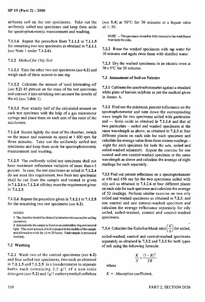
SP 15 (Part 2) :2000
airborne soil on the test specimens. Take out theuniformly soiled test specimens and keep them asidefor spectrophotometric measurement and washing.
7.1.1.6 Repeat the procedure from 7.1.1.2 to 7.1.1.5for remaining two test specimens as obtained in 7.1.1.1(see Note 1 under 7.1.2.6).
7.1.2 Method for Oily Soil
7.1.2.1 Take the other two test specimens (see 6.2) andweigh each of them nearest to one mg.
7.1.2.2 Calculate the amount of ‘used lubricating oil’
(see 5.2) 45 percent on the mass of the test specimensand convert it into ml taking into account the density ofthe oil (see Table 1).
7.1.2.3 Pour exactly half of the calculated amount oneach test specimen with the help of a gas micrometersyringe and place them on each arm of the rotor of theaccelerator.
7.1.2.4 Secure tightly the door of the chamber, switch
on the motor and maintain its speed at 1 600 rpm for
three minutes. Take out the uniformly soiled testspecimens and keep them aside for spectrophotometricmeasurement and washing.
7.1.2.5 The uniformly soiled test specimens shall not
have maximum reflectance variation of more than+ 5percent. In case, the test specimens as soiled in 7.1.2.4do not meet this requirement, two fresh test specimensshall be cut from the sample and treated as givenin 7.1.2.1 to 7.1.2.4 till they meet the requirement givenin 7.1.2.5.
7.1.2.6 Repeat the procedure given in 7.1.2.1 to 7.1.2.5
for ‘k- ----: -:-- ‘--- .,.”. “..--:----- (.. - L ->UIG lC1llclllllll~ lWU LC>L >~GbllllGL1> (A~~ U. A).
NOTES
1 The chambershould be cleanedin betweentwo successivesoilingoperations.2 Alternativelythe sampleisfixedon anembroideryringandsecuredtight. The exact amountof soil ispouredin the middleof the sampleand allowed to wick for 16to 20 hours. Each sample is processedsimilarly.
7.2 Washing
7.2.1 Wash two of the control specimen; (see 6.2)and four soiled test specimens, two each as obtainedin 7.1.1.5 and 7.1.2.5 in a Iaunderometer in separatebaths each containing 3.5 gll of a non-ionicdetergent (see 5.2) and 1g/1 carboxymethyl cellulose
310
(see 5.4) at 50°C for 30 minutes at a liquor ratioof 1:50.
NOTE — The specimensshouldbe filly exposedto the wash liquorfromboth the sides.
7.2.2 Rinse the washed specimens with tap water for10 minutes and again rinse them with distilled water.
7.2.3 Dry the washed specimens in an electric oven at70+ 5°C for 20 minutes.
7.3 Assessment of Soil on Fabrics
7.3.1 Calibrate the spectrophotometer against a standard
white plate of barium sulphate as per the method givenin Annex A.
7.3.2 Find out the minimum percent reflectance on thespectrophotometer and note down the correspondingwave length for two specimens soiled with particulatesoil — ferric oxide as obtained in 7.1.1.6 and that oftwo particulate – soiled and washed specimens at thesame wavelength as above, as obtained in 7.2.3 at fourdifferent places on each side for each specimen andcalculate the average value fi-om these sixteen readings –eight for each specimen for both the sets, soiled and
soiled-washed separately. Repeat the exercise for onecontrol and one control-washed specimen at the samewavelength as above and calculate the average of eightreadings for each separately.
7.3.3 Find out percent reflectance on a spectrophotometerat 450 and 650 nm for the two specimens soiled withoily soil as obtained in 7.1.2.6 at four different placeson each side for each specimen and calculate the averageof 32 readings. Perform similar exercise on two oilysoiled and washed specimens as obtained in 7.2.3, andone control and one control-washed specimen andcalculate the average reflectance separately for oilysoiled, soiled-washed, control and control-washedspecimens.
()7.3.4 Calculate the Kubelka-Munk ratio $ for soiled,
soiled-washed, control and control-washed specimensseparately as obtained in 7.3.2 and 7.3.3 for both typesof soil using the following formula:
K (1-//)2—.s 2R
where
K = Absorption coefficient,
PART 2, SECTION D/26
h
S=R.
Scattering coefficient, andAverage percent reflectance as measured in7.3.2 or 7.3.3.
7.3.5 Determination of Soil Resistance
7.3.5.0 This can be done correctly only in case ofparticulate soil.
7.3.5.1 Find out~value for the soiled and control
sample and determine the soil resistance as follows:
‘Oi’Resistance‘=(MC[)K = Kubelka-Munk ratio forparticulate soiled
F, sample, and
()K = Kubelka-Munk ratio for control sample.F ,,
7.3.6 Determination of Soil Release Efjciency
7.3.6.1 Calculate thedegree ofsoilretained onthe fabricspecimen separately for particulate soil and oily soilusing the formula:
D,, = Degree of soil retained on the fabricspecimen,
SP 15 (Part 2) :2000
()
K= Kubelka-Munk ratio for soiled-washed
3W specimen,
(-)
, ...-K j ‘1i
= Kubelka-Munk ratio for control-washeds ,, specimen,
(1
K= Kubelka-Munk ratio for soiled unwashed
T, specimen, and
()
K = Kubelka-Munk ratio for control unwashedT ,. specimen.
7.3.6.2 Calculate the percent soil retained on the fabric
separately for both types of soil by multiplying D,,, by100, that is, percent soil retained = D,, x 100.
7.3.6.3 Calculate the percent soil removed duringwashing for both types of soil by the formula.
Percent soil removed during washing or soil releaseefficiency = 100( I –D,,) where D,, is the value obtainedin 7.3.6.1.
8 REPORT
The report shall include the following information:
a) Nature, type and constructional details of fabricbeing tested;
b) Nature, and type of finish given to the fabric;
c) Percent soil retained on the fabric after washingseparately for the particulate and the oily soil;
d) Soil release efficiency separately for the~,
particulate and the oily soil; and
e) Soil resistance of the fabric or garment forparticulate soil only.
PART 2, SECTION D/26 311
I
I,’ I
I
I
SP 15 (Part 2) :2000
ANNEX A
(Clause 7.3. 1)
METHOD FOR CALIBRATION OF SPECTROPHOTOMETER
—--
A-1 Keep the spectrophotometer in an air-conditioned A-4 Keep the white plate coated with barium sulphate
chamber at 27 + 2 ‘C. below the sensor and calibrate the instrument at aninterval of 10 nm. Set the reading to 100 + 0.5 on the
A-2 Switch on the instrument about 90 minutes before digital panel, each time.
use.A-5 Calibrate the instrument for the full range of
A-3 Set the arbitrary value, given with the instrument, wavelength from 380 to 760 nm. The instrument is
on the panel. now ready for recording the measurements.
4.
312 PART 2, SECTION D/26
/
A--
SP 15 (Part 2) :2000
DETERMINATION OF FLAMMABILITY ANDFLAME RESISTANCE OF TEXTILE FABRICS
(Source : IS 11871: 1986)
The flammability is one of the important properties of textile materials, besides characteristics like combustion,thermal degradation, shouldering, after glow, smoke and toxicity. With the increasing awareness of fire hazardsand promulgation of rules and regulations by several advanced countries, the development of flammability standardneeds no emphasis.
1 SCOPE
It prescribes two methods for determining the
flammability and flame resistance of textile fabrics. Itapplies to all types of textile fabrics, clothing andgarments whether woven, knitted, bonded, laminated
or surface coated.
2 APPLICATION
2.1 Method A based on vertical flame test is
recommended for evaluating flame resistance of all typesof textile fabrics. Method B based on 45° inclinationflame test covers the evaluation of flammability of textile
clothing and textiles intended to be used in clothing.
2.1.1 The methods described are not applicable to rugsand carpets and for interior fabrics used for passenger
vehicles.
3 DEFINITIONS
For the purpose of this standard, the following definitions
shall apply.
3.1 Flammability
The characteristics of a material which pertain to itsrelative ease of ignition and relative ability to sustain
combustion.
3.2 Flame
As related to textile flammability, a hot, luminous zoneof gas or matter in gaseous suspension, or both, that is,undergoing combustion, which is relatively constant insize and shape and which produces a relatively low heatflux.
3.3 Ignition
Flaming of the specimen for a period of 1 s or more
after the removal of the igniting source.
PART 2, SECTION D/27
3.4 Flashing
The sudden transition of a state of total surfaceinvolvement in a f~e of combustible material within a
compartment.
3.5 Flame-Retardant
A chemical used to impart flame resistance.
3.6 Flame-Retardant Finish
A process for incorporating or adding flame retardant(s)to a material or product.
3.7 Flame-Resistance
The property of a material whereby flaming combustionis prevented, terminated, or inhibited followingapplication of a flaming or non-flaming source ofignition, with or without subsequent removal of theignition source. The degree of flame resistance exhibitedby a specific material during testing may vary withdifferent test conditions.
3.8 Flame Resistant
The material having flame resistance.
NOTE— ‘Flameresistant’is a mandatory description fora productthatmeetsestablishedconformancestandardwhenthe productistestedbyaspecificmethod.Wherenoconformancestandardexists,‘flameresistant’isa relativetermandisusedto compareone materialwithanother.
3.9 Flame-Proof Fabric
A fabric which does not propagate flame; that is, anyflame goes out quickly when the igniting flame iswithdrawn.
3.10 Glow
Visible, flameless combustion of the solid phase of amaterial.
313
/
I?,
I I
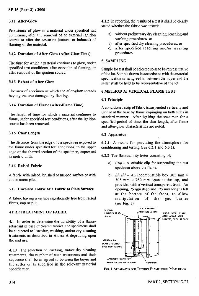
SP 15 (Part 2) :2000
3.11 After-Glow
Persistence of glow in a material under specified testconditions, after the removal of an external ignitionsource or after the cessation (natural or induced) offlaming of the material.
3.12 Duration of After-Glow (After-Glow Time)
The time for which a material continues to glow, underspecified test conditions, afler cessation of flaming, orafter removal of the ignition source.
3.13 Extent of After-Glow
The area of specimen in which the after-glow spreadsbeyong the area damaged by flaming.
3.14 Duration of Flame (After-Flame Time)
The length of time for which a material continues toflame, under specified test conditions, after the ignitionsource has been removed.
3.15 Char Length
The distance from the edge of the specimen exposed tothe flame under specified test conditions, to the upperedge of the charred section of the specimen, expressedin metric units.
3.16 Raised Fabric
A fabric with raised, brushed or napped surface or withcut or uncut pile.
3.17 Unraised Fabric or a Fabric of Plain Surface
A fabric having a surface significantly free from raisedfibres, nap or pile.
4 PRETREATMENT OF FABRIC
4.1 In order to determine the durability of a flame-retardant in case of treated fabrics, the specimens shallbe subjected to leaching, washing, and/or dry cleaningtreatments as described in Annex A depending uponthe end use.
4.1.1 The selection of leaching, and/or dry cleaningtreatments, the number of such treatments and theirsequence shall be as agreed to between the buyer andthe seller or as specified in the relevant material
specification.
314
4.1.2 In reporting the restdts of a test it shall be clearly
stated whether the fabric was tested:
a)
b)c)
without preliminary dry cleaning, leaching andwashing procedures, or
after specified dry cleaning procedures, orafter specified leaching andlor washingprocedures.
5 SAMPLING
Sample for test shall be selected so as to be representativeof the lot. Sample drawn in accordance with the materialspecification or as agreed to between the buyer and theseller shall be held to be representative of the lot.
6 METHOD A: VERTICAL FLAME TEST
6.1 Principle
A conditioned strip of fabric is suspended vertically andignited at the base by flame impinging on both sides in
standard manner. After igniting the specimen for aspecified period of time, the char length, after-flameand after-glow characteristics are noted.
6.2 Apparatus
6.2.1 A means for providing the atmosphere forconditioning and testing (see 6.3.1 and 6.3.2).
6.2.2 The flammability tester consisting of
a)
b)
SLIDING
Clip – A suitable clip for suspending the testspecimen above the flame.
Shield – An incombustible box 305 mm x305 mm x 760 mm open at the top, andprovided with a vertical transparent front. Anopening, 25 mm deep and 125 mm long is leftat the bottom of the front, to allowmanipulation of the gas burner(see Fig. 1).
GLIPSUSPENDED
TRANSPARENT, rFCF4M STEEL EAR
WELD (STEEL PLATE
FRONT \ \ ,WH ANGLE -lRoN
CC.RNERS, DPEN AT
i%’ii’’%lw‘“
TOP )
APERTURE TO PERMIT’
MANIPULATION OF BuRNER \ BuRNER
FIG. 1 APPARATUSFORTESTINGFLAMEPROOFMATERIALS
PART 2, SECTION D/27
—4’4-q
i
.-
/%.,
,~--
.—
SP 15 (Part 2) :2000
c)
d)
e)
o
g)
Gas burner – A Bunsen burner about 150 mmhigh with an internal diameter of 9 mm.
Specimen holder– Consisting of two U - shapedmetal plates between which the fabric specimencan be held in such a way that the fabricspecimen is free at the bottom and is held atthe top and sides so that the total exposed areais 50 mm x 305 mm. The specimen holderwill be positioned in the draught-free boxvertically so that the igniting flame strikes thespecimen centrally and 19 mm above thebottom edge of the specimen.
Clamps – These maybe plain or serrated springclips or small clamps. When made of smoothmaterial, it may be necessary to insert emerypaper to increase friction.
Weights – Weights such as are used withlaboratory pan balances are satisfactory. Asuitable pan may be made from a laboratory
balance tray and wire.
Stenterpinplates – Two stenter pin plates, eachconsisting of a flat plate carrying pointed pinsattached to one side of its broad surface, toprevent movement of the lower end of the test
specimen during the application of the testflame. Each plate is secured at one end to theside of the shield in the horizontal position.
6.2.3 A Stop-watch – with an accuracy up to 0.1 second.
6.3 Conditioning and Testing Atmospheres
6.3.1 Conditioning – Before testing, condition thespecimens for 24 h in a standard atmosphere of 65 k 2percent relative humidity and 27+ 2°C temperature (seeIS 6359:1971 ‘Method for conditioning of textiles’) givenin section B-1/1. If the testis not carried out immediatelyafter conditioning, place the specimens in a tightly closedcontainer until the commencement of the test. Eachspecimen shall be tested within two minutes of removingit from either the conditioning atmosphere or thecontainer.
6.3.2 Testing Atmosphere – Carry out the test in asubstantially draught-free room or enclosure in anatmosphere of relative humidity between 20 to 80 percentand temperature between 20 to 35”C.
6.4 Test Specimens
6.4.1 The test specimen shall be 315 mm long x 50mm wide. It shall be prepared in accordance with 6.4.2.
PART 2, SECTION D/27
6.4.2 Six specimens, where appropriate, three in warpdirection and three in weft direction shall be cut fromthe sample (5) so as not to include selvedge (see Note).They shall be cut from three widely separated sectionsof the sample. The specimens shall be conditioned asspecified in 6.3.1.
NOTE — The test specimen should not have loose threads or anyformof tilnge along itsedges,that might affectthe ease of ignition,cause initial tlwingor flashingandthusprejudicethe test.
6.5 Procedure
6.5.1 Keep the apparatus in a substantially draught-fiee room or enclosure (see Note 2) having atmosphereas described in 6.3.2. Suspend the test specimen fromthe clip so that it hangs vertically, with its lower endheld by the horizontal stenter pin plates in such a waythat the bottom 6 mm of the specimen is attached to thehorizontal stenter pins thereon. The plates shall be sofixed that not more than 9 mm of the specimen on either
side is covered by them.
NOTES1 In case of fabrics that shrink on burning, specimens maybe mountedon suitablespecimenholders so that the two longedgesare held securely. In this case, the size of each specimenshall be 70 mm x 315 mm so that the total exposed area is50mmx 305mm.
2 Becausethetestiscarriedoutinadraught-tleeroom,theairintheroom is likely to become contaminatedwith the products ofcombustion. Where these products include potentially toxicsubstances,forexampIe,hydrochloricacid,phosphorouscompounds,etc,amaskorrespiratorcapableofremovingthesesubstancesshouldbeworn,or thetestmayconvenientlybe carriedout in tirmehoodwiththedraughtshutoff. Ifobnoxiousfumesareproduced,thesemayberemovedbyturningonthedraughtbetweenthe test(s).
6.5.2 Shut off the air supply to the gas burner completelyand adjust to give a luminous flame 38 mm in length.Place the gas burner such that the base of the flame is19 mm below the middle of the lower edge of thespecimen. Apply the flame for a period of 12 seconds tothe mid-point of the lower edge of the specimen andthen withdraw the flame.
6.5.3 Record the duration of flaming, extent of at3er-glow, the duration of after-glow and occurrence offlashing over the specimen.
6.5.4 When the afier-glow has ceased, remove the test
specimen from the clip and stenter pin plates and attachtwo clamps, one on each side of the charred area, 6 mmfrom lower edge of the test specimen. Attach a weightto one clamp gently so that combined weight is equal toabout 10 percent of that required to tear the unburnt
315
i,

SP 15 (Part 2) :2000
material. Measure the length of char or melt to thenearest 5 mm as the difference between the originallength of test specimen and the distance of the unexposededge to the end of the tear made on the test specimen.
NOTES1 If the material under testis made up of a thermoplastic tibre, itmay be necessary to make a small cut vertically (with a pair ofscissors or razor blades) through the area of resolidified polymerwhich extentsroundthe charredareas. The clampsarethen attachedand the material is tested by the method as described above.
2 In order to determine the weight required to tear the unburntmaterial, an unburnt specimen is laid on a table and a cut, about6 mm long, made in the middle of one end. A clamp is attachedto the material on each side of the cut, and a weight is attachedto the clamp on one side. The material is then gently lifted bythe other clamp and the cut is observed. The process is repeated,if necessary, until the minimum weight necessary to tear thematerial is found. The combined weight of the clamp andattached weights is taken as the weight required to tear theunburnt material.
6.5.4.1 Alternatively, the char length may be measuredby the method prescribed in Annex B.
6.6 Report
Report the following separately for each specimen beforeand after the leaching, washing andlor dry cleaning
treatments:
a)
b)
c)
d)
e)
f)
Whether or not flashing occurs over the surface
of the specimen;
Duration of flame (after-flame time) in seconds;
Duration of after-glow in seconds;
Char length to the nearest 5 mm;
Extent of after-glow; and
Any abnormal behaviour occurring under theinfluence of the flame – for example, meltingdripping, shrinking from the flame and abnormalcharring.
7 METHOD B : THE 45° FLAME TEST
7.1 Principle
Specimens cut from the textile are prepared by brushingif they have a raised fibre surface, by dry cleaning andlaundering if they have a flame-retardant finish and bydrying. The dried specimen of the fabric is held at anangle of 45° to the horizontal and a standardized flameis applied to the surface near the lower end for 1 s. Thetime required for flaming to proceed up the fabric adistance of 127 mm is measured. Ignition or fusing ofthe base of specimens having a raised fibre surface isnoted.
316
7.2 Apparatus
7.2.1 Flammability Tester
7.2.1.1 Draught-proof box
Consisting of a ventilated draught-proof box(370mm X 220mm X 140mm approx) containingstandard ignition mechanism and a specimen rackinclined at 45° and adjustable laterally so that the surfaceof the tested fabric will be at a standard distance fromthe micro-burner. For ventilation it shall be providedwith 12 holes each 13 mm in diameter equidistantlyspaced, near the top of the rear wall and by a slit300 mm long and 13 mm wide (or any equivalentventilating strip) below the sliding glazed door. Theglazed door slides in grooves at the front of the cabinet.A knob moves the catch mechanism used to hold thesliding door in an open position for insertion of thespecimen holders.
7.2.1.2 Specimen rack
It provides support for the frames in which the specimensare mounted. The angle of inclination is 45 degrees.
Two guide pins projecting downward from the centre ofthe base of the rack, travel in slots provided in the floorof the chamber so that adjustment can be made for thethickness of the specimen in relation to the flame front.An indicating finger is provided, the forepart of whichtouches the specimen when the rack is correctly adjusted.Two control knobs hold the rack in test position. Theknobs can be reached under the stage of the cabinet andpermit forward and backward movements of the rackwhen loosened.
7.2.1.3 Specimen holders
Each specimen holder shall consist of two matched metalU-plates between which the fabric can be held in such away that the fabric specimen is free at the bottom and isheld at the top and sides with 40 mm of width and150 mm of length exposed. The specimen holder shallbe so made that it will drop on the specimen rack into aprecisely determined position of 45° inclination and willbe positioned in the specimen rack so that the ignitingflame strikes the specimen centrally and 6 mm abovethe bottom edge. Five specimen holders are provided.
7.2.1.4 Ignition mechanism
The ignition mechanism shall comprise a micro-burnermounted on a rotatable spindle so that, at thecommencement of each test, it moves to a position
PART 2, SECTION D/27
-.
}+,
SP 15 (Part 2) :2000
perpendicular to the surface of the fabric; the respectiveparts of the apparatus shall be so disposed that the end
of the micro-burner is 8 mm above the upper surface offabric. A flame 16 mm long shall be produced at the
micro-burner by butane gas or petroleum gas (see Noteunder 7.3. 1) taken from a small cylinder, a sensitive
reducing valve and a manometer device. The ignitionmechanism provided shall be such that the flame is
maintained in the igniting position for the duration of
the test. It shall be provided with means for the timingof the interval (in seconds to the nearest 0.1 second)
from the moment of first impingement of the flame onthe fabric specimen to the time when the weighed cotton
thread is burnt through. The cotton thread is stretchedfrom a guide ring through suitable thread guides
provided on the specimen frame and chamber walls,
permitting the lacing of the thread in the proper position
exactly 127 mm from the point where the centre of theignition flame impinges on the test specimen. A weight
attached by means of a clip to the cotton thread, in
dropping, actuates the stop motion.
7.2.1.5 End point
The end point of the test is indicated by the burningthrough of a weighted cotton thread horizontally
mounted across the specimen holder 127 mm from thepoint of ignition and not more than 6 mm above the
surface of the specimen.
7.2.2 Brushing Device
7.2.2.1 Movable carriage
The brushing device consists of a base board over whicha small carriage is drawn. This carriage runs on paralleltracks attached to the edges of the upper surface of thebase board. A brush is hinged with pin hinges at therear edge of the base board and rests on the carriagevertically with a pressure of 150 g. The carriage is soconstructed as to receive the specimen in its holder andto permit its longitudinal brushing as the carriage isslowly moved beneath weighed brush.
7.2.2.2 Brush
40 mm long, comprising two rows of nylon monotil tufts
0.4 mm in diameter and 20 mm in length mounted in a
staggered position. There are four tufts per 25 mm andeach tuft contains 20 filament ends. The brush ismounted so that it may move freely in a vertical direction
and is weighted so that it rests on a horizontal surfacewith a load of 150 g.
NOTE — For forther details, ASTM D 1230-1972 (issued by theAmericanSociety for Testing and Materials) may be referred.
7.2.3 Laboratory Drying Oven — maintained at105 * 3°c.
7.2.4 Desiccator – 250 mm in diameter.
7.2.5 Mercerized Cotton Sewing Thread
Corresponding to variety No. 20 of IS 1720: 1978‘cotton sewing thread’.
7.2.6 Worsted Test Fabric
Well scoured, undyed worsted cloth, plain weave, 170to 180 g/m2.
7.3 Reagents
7.3.1 Butane gas
NOTE — In place of butaoe gas, commerically available liquefiedpetroleum gas (LPG ) may also be used.
7.3.2 Calcium Chloride (Anhydrous)
7.4 Test Specimens
7.4.1 Five test specimens each measuring 150 mm x
50 mm shall be selected as given in 7.4.2 for each testand prepared as described in 7.4.3.
7.4.2 Determination of the Type of Specimen
Before specimens for the standard test are cut, establishby preliminary tests which type of specimen gives thehighest observed burning rate. Conduct the preliminarytests as follows:
a)
b)
Unraisedfabrics – Test one specimen cut in thewarp or length direction of the fabric and onecut in the weft or width direction. If there is aface side to the fabric these specimens shall betested with the face side uppermost and twoadditional specimens shall be tested with the faceside downwards.
Raised fabrics – Fabrics raised on one surfaceonly are always tested with the raised surfaceuppermost. Prepare two specimens cut in thewarp direction, and test one with the lie of thenap or pile upwards and one with the lie
downwards. Prepare two specimens cut in theweft direction and test these also in both
PART 2, SECTION D/27 317
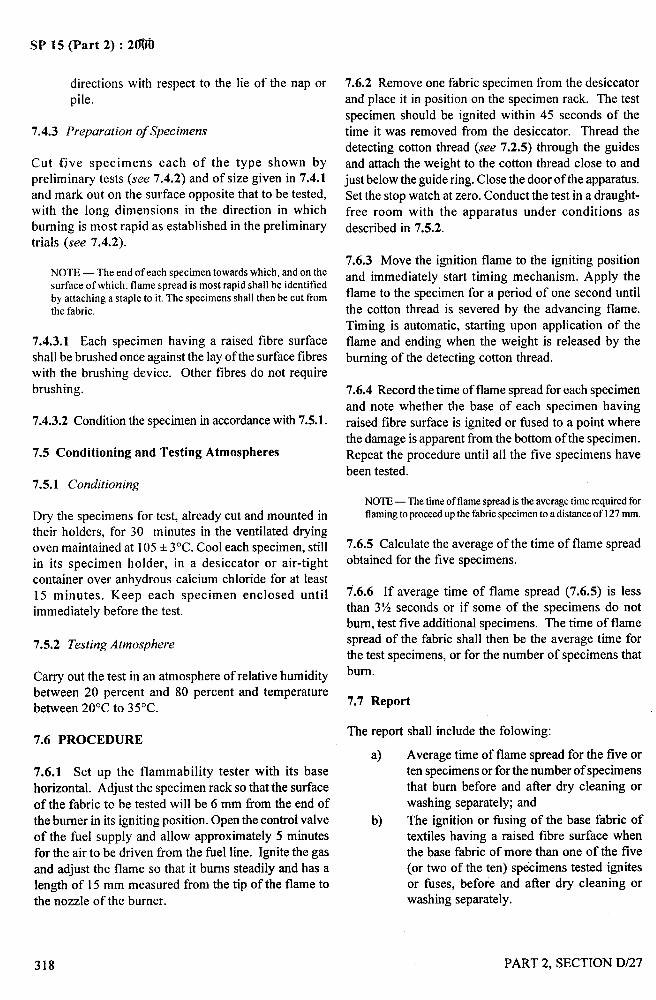
SP 15 (Part 2) : 2@@l
directions with respect to the lie of the nap orpile.
7.4.3 Preparation of Specimens
Cut fjve specimens each of the type shown bypreliminary tests (see 7.4.2) and of size given in 7.4.1and mark out on the surface opposite that to be tested,with the long dimensions in the direction in which
burning is most rapid as established in the preliminarytrials (see 7.4.2).
NOTE — The end of each specimen towards which, and on thesurface of which, flame spread is most rapid shall be identifiedby attaching a staple to it. The specimens shall then be cut fromthe fabric.
7.4.3.1 Each specimen having a raised fibre surfaceshall be brushed once against the lay of the surface tibreswith the brushing device. Other fibres do not require
brushing.
7.4.3.2 Condition the specimen in accordance with 7.5.1.
7.5 Conditioning and Testing Atmospheres
7.5.1 Conditioning
Dry the specimens for test, already cut and mounted intheir holders, for 30 minutes in the ventilated dryingoven maintained at 105 + 3“C. Cool each specimen, stillin its specimen holder, in a desiccator or air-tight
container over anhydrous calcium chloride for at least15 minutes. Keep each specimen enclosed untilimmediately before the test.
7.5.2 Testing Atmosphere
Carry out the test in an atmosphere of relative humiditybetween 20 percent and 80 percent and temperaturebetween 20°C to 35”C.
7.6 PROCEDURE
7.6.1 Set up the flammability tester with its base
horizontal. Adjust the specimen rack so that the surface
of the fabric to be tested will be 6 mm ffom the end ofthe burner in its igniting position. Open the control valve
of the fuel supply and allow approximately 5 minutes
for the air to be driven from the fuel line. Ignite the gasand adjust the flame so that it bums steadily and has alength of 15 mm measured from the tip of the flame tothe nozzle of the burner.
7.6.2 Remove one fabric specimen from the desiccatorand place it in position on the specimen rack. The test
specimen should be ignited within 45 seconds of the
time it was removed from the desiccator. Thread thedetecting cotton thread (see 7.2.5) through the guidesand attach the weight to the cotton thread close to and
just below the guide ring. Close the door of the apparatus.
Set the stop watch at zero. Conduct the test in a draught-free room with the apparatus under conditions as
described in 7.5.2.
7.6.3 Move the ignition flame to the igniting position
and immediately start timing mechanism. Apply the
flame to the specimen for a period of one second until
the cotton thread is severed by the advancing flame.
Timing is automatic, starting upon application of theflame and ending when the weight is released by the
burning of the detecting cotton thread.
7.6.4 Record the time of flame spread for each specimen
and note whether the base of each specimen having
raised fibre surface is ignited or fused to a point wherethe damage is apparent from the bottom of the specimen.
Repeat the procedure until all the five specimens have
been tested.
NOTE—Thetime offlamespreadistheaveragetimerequiredforflamingtoproceedup the fabricspecimen to a distance of 127mm.
7.6.5 Calculate the average of the time of flame spreadobtained for the five specimens.
7.6.6 If average time of flame spread (7.6.5) is less
than 3?4 seconds or if some of the specimens do notbum, test five additional specimens. The time of flamespread of the fabric shall then be the average time forthe test specimens, or for the number of specimens that
bum.
7.7 Report
The report shall include the folowing:
a) Average time of flame spread for the five orten specimens or for the number of specimensthat bum before and after dry cleaning orwashing separately; and
b) The ignition or fusing of the base fabric oftextiles having a raised fibre surface whenthe base fabric of more than one of the five(or two of the ten) specimens tested ignitesor fuses, before and atler dry cleaning orwashing separately.
318 PART 2, SECTION D/27
SP 15 (Part 2) :2000
ANNEX A
(Clause 4.1)
LEACHING, WASHING AND DRY CLEANING TREATMENTS OF FABRICS
A-1 LEACHING TREATMENT
A-1.1 General
This treatment is applicable to non-apparel fabrics suchas awnings, hatch covers and theatre curtains whichwould not normally be subjected to water or to dry-cleaning in use but which might be subjected to spot
cleaning or casual rinsing, for example, under a tap. Itis also used as a preliminary treatment to the drycleaningprocedure in order to remove water soluble finisheswhich, in use, may be affected by wetting. There is noobjection to steeping together similar fabrics with thesame finish.
A-1.2 Specimens
Use sufficient fabric to permit subsequent preparationof test specimens of the size and number required inMethod A or B.
A-1.3 Reagents
A-1 .3.1 Water – of 160 + 20 mg/1 hardness (expressedas calcium carbonate) ti-om one of the following sources:
a)
b)
c)
Supply water of 160+20 mg/1 hardness.
Supply water of higher than 180 g/1 hardnessand diluted to 160+20 mg/1 hardness with waterof lower hardness.
Supply water of known initial hardness of ‘n’mg/1 where n is less than 140 mg/1 andartificially hardened to 160+20 mg/1. To 5 litresof the water add 500 ml of the calcium chloridesolution (see A-1.3.2) and follow this with500 ml of the sodium hydrogen carbonatesolution (see A-1.3.3) and then sufficient of thewater to give a total of 10 + 0.1 litres.
A-1 .3.2 Calcium Chloride Hexahydrate
43.8 (160 – n) mg/1 solution in water of hardness n mg/1.
A-1 .3.3 Sodium Hydrogen Carbonate
33.6 (160 – n) mg/1 solution in water of hardness n mg/1.
PART 2, SECTION D/27
A-1 .3.4 Non-ionic Wetting Agent
Conforming to IS 9458:1994 ‘Synthetic detergents forwashing woollen and silk fabrics’.
NOTE — The exact nature of the wetting agent is not critical,
A-1.4 Apparatus
A-1 .4.1 Flat-Bottomed Dish
A-1.4.2 Iron or Press – to be used at a temperaturesetting not exceeding 120°C.
A-1.5 Procedure
A-1 .5.1 Immerse each specimen in water (see A-1.3.1)containing 0.5 gll of non-ionic wetting agent in the tlat-bottomed dish at liquor ratio of 1:20 at a temperature of40+ 1“C. After 30 minutes, remove the specimen, rinse
in the water (see A-1.3.1) using a liquor ratio of 1:20for 2 minutes, partially dry the specimens by any methodsuitable for the fabric type and then iron or press at atemperature setting not exceeding 120°C.
A-2 HARD WATER WASHING TREATMENTUSING NEUTRAL SOAP OR SYNTHETICDETERGENT SOLUTION
A-2.1 General
This treatment is applicable to those fabrics which wouldnormally be subjected to a water wash treatment in use.
A-2.2 Specimens
Use sufficient fabric to permit subsequent preparationof test specimens of the size and number required inMethod A or B.
A-2.3 Apparatus
A-2.3.1 A mechanical washing device, for example,wash-wheel sponsored by the Society of Dyers andColorists or the Iaunderometer sponsored by theAmerican Association of Textile Chemists andColorists (see also IS 1299 : 1984 ‘Method fordetermination of dimensional changes on washing of
319
,,I
I
I
I
I
/
L..-.L
SP 15 (Part 2) :2000
fabrics woven from rayon and synthetic tibres’ given in A-2.5.3 Keep the washing conditions as follows:
Section C/6) Whichever type of machine is used, thevolume of the container should be at least twice that of S1 Composition of Solution Washing
the washing solution. All the material subjected to No. Fabric Temperature Time, ruin
washing should be of the type under test; the use of otherO Cottonandlinentibres
materials as loading material may give erroneous results.80 to 85°C or60 to 70”C
30
ii)A-2.4 Reagents
Polyamide,polyester, 55 to 60”C 30
regeneratedcelhdosic
A-2.4.1 SOUPfibres
iii) Wool, silkand acetatetibres 38 to 40°C 10
Meeting the composition as specified in 7.1 ofiv) Acrylics,chlorotibresand 38to 40”C 30
modacrylicfibresIS 1299:1984 ‘Method for determination of dimensionalchanges on washing of fabrics woven from rayon andsynthetic fibres’ given in Section C/6. A-3 SOFT WATER WASHING TREATMENT
A-2.4.2 Non-ionic Wetting Agent A-3.1 General
Based on ethylene oxide fatty alcohol condensateconforming to IS 9458: 1994. ‘Synthetic detergents forwashing woollen and other delicate fabrics’.
A-2.4.3 Sodium Dihydrogen Phosphate – anhydrous(NaH,PO,).
A-2.4.4 Disodium Hydrogen Phosphate – anhydrous(Na2HP0,).
A-2.4.5 Hard Water
With a hardness of 160 +20 mg/1 (expressed as calcium
carbonate) (see A-1 .3.1).
A-2.5 Procedure
A-2.5. 1 Treat the specimens in suitable mechanical
washing device (see A-2.3.1) as given in IS 1299:1984
‘Method for determination of dimensional changes on’
washing of fabrics woven from rayon and synthetic
fibres’ given in section C/6 for a period given in A-2.5.3
with sufficient washing liquor containing 5 gll soap
(see A-2.4.1) and hard water (see A-2.4.5) to give a
liquor ratio of 1:10 (m/m).
A-2.5.2 Alternatively, instead of soap, a neutral
synthetic detergent solution of following composition
may be used: Sodium dihydrogen phosphate, anhydrous
( NaH2P0,) -0.1 g/1. Disodium hydrogen phosphate,
anhydrous (NazHPO~) – 0.2 g/1. Non-ionic wetting agent
of the ethylene oxide fatty alcohol condensate type –
0.05 g/1. Hard Water – to make the required volume.
NOTE— The pH of the solution in A-2.5.2 shall be adjustedto 7.0* 0.2.
This treatment is applicable to those fabrics employedin end uses to which laundering will be applied.
A-3.2 Specimens
Use sufficient fabric to permit subsequent preparationof test specimens of the size and number required inMethod A or B.
A-3.3 Apparatus
A-3.3.1 A Mechanical Washing Device – (see A-2.3.1).
A-3.4 Reagents
A-3.4.1 Water
With a maximum hardness of 20 mg/1 (expressed ascalcium carbonate).
A-3.4.2 Soap
Meeting the composition specified in 7.1 of IS 1299:1984 ‘Method for determination of dimensional changes
on washing of fabrics woven from rayon and syntheticfibres’ given in Section C/6 and containing 3 percent
sodium carboxymethyl cellulose.
A-3.4.3 Non-ionic Wetting Agent
Based on ethylene oxide condensate conforming to
IS 9458:1994 ‘Synthetic detergent for washing woollenand silk fabrics’.
A-3.4.4 Sodium Meta Silicate
Conforming to IS 9424:1979 ‘Sodium metasilicate’.
..
g..-.
320 PART 2, SECTION D/27
SP 15 (Part 2) :2000
A-3.5 Procedure
A-3.5.1 Treat the fabric in a suitable mechanical
washing device by the procedure specified inIS 1299:1984 ‘Method for determination of dimensional
changes on washing of fabrics woven from rayon andsynthetic fibres’ given in Section C/6 for a period andat a temperature given in A-2.5.3 with sufficient washingliquor containing 5 g/1 soap, 0.5 g/1 non-ionic wetting
agent, 3.5 g/1 sodium metasilicate and soft water(see A-3.4.1) to give a liquor ratio of 1:10 (rrdnr).
A-4 DRY CLEANING TREATMENT
A-4.1 General
This treatment is applicable to those fabrics which wouldnormally be subjected to a dry cleaning treatment.
A-4.2 Specimens
Use sufficient fabric to permit subsequent preparation
of test spec;mens of the size and number required inMethod A o; B.
A-4.3 Reagents
A-4.3.1 Perchloroethylene or Petroleum Ether – dry
cleaning grade.
NOTE — Perchioroethylene should be stored over anhydroussodium carbonateto neutralize any hydrochloricacid formed.
A-4.4 Apparatus
A-4.4.1 Suitable mechanical device consisting of awater bath containing a rotatable shaft which supports,radially, glass or stainless steel containers (75 + 5 mm
diameter x 125+ 10 mm high) of approximately 55o +50 ml capacity, the bottom of the containers being 45 +10 mm from the centre of the shaft The shaft/containerassembly is rotated at a frequency of 40 + 2 rein-’. Thetemperature of the water bath is thermostaticallycontrolled to maintain the test solvent at 30 A 2“C.
NOTE— Other mechanical devices may also be used for the testprovided that the results are identical with those obtained by theapparatusdescribedunder A-4.4.1.
A-4.4.2 Glass or stainless steel containers ofapproximately 550 ml capacity which shall be closedusing solvent resistant gaskets.
A-4.4.3 Non-corrodible (stainless) steel discs,30+ 2 x 3 + 0.5 mm, smooth and free from rough edgesof mass 20 + 2 g.
A-4.5 Procedure
A-4.5.1 Prepare a bag with inside dimensions of10 cm x 10 cm using the undyed cotton twill cloth bysewing together two squares of this cloth around three
sides. Place the specimen and 12 steel discs inside thebag. Close the bag by any convenient means.
A-4.5.2 Place the bag containing the specimen and thesteel discs in the container and add 200 ml of drycleaning solvent at 30 + 2°C. Treat the specimens for30 minutes at 30 + 2°C in the specified mechanicaldevice as specified in A-4.4.1.
A-4.5.3 Remove the bag from the container, withdrawthe specimens, place it behveen the absorbent paper orcloth and squeeze or centrifuge to remove surplussolvent. Dry the specimen by hanging it in air at atemperature not exceeding 60”C.
““:1
PART 2, SECTION D/27 321
, I
I !,
I

SP 15 (Part 2) :2000
ANNEX B
(Clause 6.5.4.1)
MEASUREMENT OF CHAR LENGTH
B-1 APPARATUS
B-1. 1 A hook and weight assembly. The combinedmass of the assembly should be as given in Table 1.
Table 1 Mass to Tear Charred Fabric
SI Mass of Fabric Total MassNo. Being Tested Used to
Q/m’) Tear the Fabric
i) Less than 200 I00ii) 200 to 600 200
iii) Greater than 600 400
B-2 PROCEDURE
B-2. 1 Inspect the edge of the highest char penetrationof the specimen to determine if as a result of
thermoplastic behaviour, a thickening of the edge hasdeveloped. If this has occurred, make a cut after cooling,
only sufficiently deep to cut through the highest portionof this thickened edge of the charred specimen.
B-2.2 Fold the specimen parallel to its length and creaseit lightly through the maximum visible portion of the
charred length.
B-2.3 Insert the hook with total mass as given in
Table 1, in the specimen one side of the charred area,
8 mm in from the adjacent out-side edge of the charredlength.
B-2.4 Grasp the specimen with fingers on the opposite
side of the charred area and raise gently until it supportsthe weight. The fabric will tear through the area until
fabric strong enough to carry the load is reached.
B-2.5 Measure the distance from the end of the
specimen which was exposed to the flame to the end of
a tear made lengthwise in the specimen through thecentre of the charred area, as the char length.
322 PART 2. SECTION D/27
A.-
_ .—
SP 15 (Part 2) :2000
DETERMINATION OF FLAMMABILITY BY OXYGEN IN~EX —.
(Source : IS 13501: 1992)~.. .
Oxygen index results obtained using this method can provide a sensitive measure of the burning characteristics of ‘~~,
a textile material intended for clothings under certain controlled laboratory conditions, and hence may be usefulfor quality control purposes. The results obtained are dependent upon the shape, orientation and isolation of thetest specimen and conditions of ignition. For particular materials or applications, it maybe necessary or appropriateto specify different test conditions. Results obtained from test specimens of differing thickness or by using differentignition porcedures may not be comparable and no correlation with flammability behaviour under other fire conditionsis implied.
Results obtained in accordance with this method must not be used to describe or appraise the fire hazard presented
by a particular textile material or shape under actual fire conditions, unless used as one element of a fire riskassessment that takes into account all the factors pertinent to the assessment of the fire hazard of a particularapplication for the textile material,
1 SCOPE
1.1 [tspecifies method for determining the minimumconcentration of oxygen, in admixture with nitrogen,that will support combustion of small vertical testspecimens under specified test conditions. The resultsare defined as oxygen index values.
1.2 The method provides a sensitive measure of theburning characteristics of textile materials intended forclothings.
2 PRINCIPLE
A small test specimen is supported vertically in a mixtureof oxygen and nitrogen flowing upwards through atransparent chimney. The upper end of the specimen isignited. The minimum concentration of oxygen in amixture of oxygen and nitrogen flowing upward in atest chimney that will just support combustion ismeasured under equilibrium conditions of candle likeburning. The equilibrium is established by the relationbetween the heat generated from the combustion of thespecimen and the heat lost to the surroundings asmeasured by one or the other of two arbitrary criteria,namely, the period for which burning continues, or thelength of specimen burnt. This point is approached fromboth sides of the critical oxygen concentration in orderto establish the oxygen index.
3 TERMINOLOGY
For the purpose of this standard the definitions given in1S 11871 : 1986 ‘Methods for determination offlammability and flame resistance of textile fabrics’ andthe following definition shall apply.
3.1 Oxygen Index
The minimum concentration of oxygen by percentagevolume in a mixture of oxygen and nitrogen that willjust support combustion of material under specitied testconditions.
4 APPARATUS
The following apparatus shall be arranged as indicatedin Fig. 1 and 2.
4.1 Test Chimney
A heat resistant glass tube supported vertically on a basethrough which oxygen-containing gas mixture can beintroduced. The preferred dimensions of the chimney
are 450 mm minimum height and 75 mm minimumdiameter cylindrical bore. The upper outlet shall berestricted as necessary by an overhead cap having anoutlet small enough to produce an exhaust velocity of atleast 90 mm/s from a flow rate within the chimney of30 mm/s (see Note), “Chimneys of other dimensions, withor without restricted outlets, may be used, if shown togive equivalent results. The bottom of the chimney, orthe base upon which the chimney is supported, shallincorporate a means for distributing evenly the gasmixture entering the chimney. The preferred meanscomprises solid glass beads of between 3 and 5 mmdiameter, in a layer between 80 and 100 mm deep. Othermeans, such as radial manifolds, may be used, if shownto give equivalent results. A porous screen may bemounted below the level of the specimen holder, toprevent falling combustion debris from fouling the gasentry and distribution paths. The chimney support mayincorporate a leveling device and indicator, to facilitate
},,.,
PART 2, SECTION D/28 323
I
II
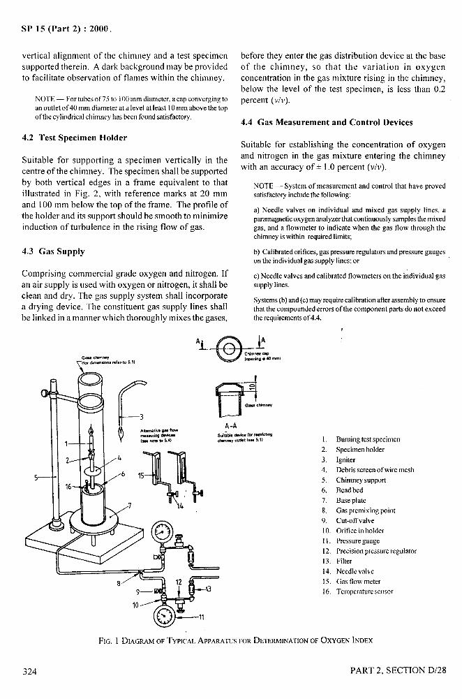
. &.—
1. . . .
SP 15 (Part 2) :2000,
vertical alignment of the chimney and a test specimen
supported therein. A dark background maybe provided
to facilitate observation of flames within the chimney.
NOTE — For tubesof7510 iO(Imm diameter. a cap convergingtoan outlet of40 mm diameter at a level at least 10mm abovethe topof the cylindrical chimney has been foundsatisfactory.
4.2 Test Specimen Holder
Suitable for supporting a specimen vertically in thecentre of the chimney. The specimen shall be supportedby both vertical edges in a frame equivalent to thatillustrated in Fig. 2, with reference marks at 20 mm
and 100 mm below the top of the frame. The profile ofthe holder and its support should be smooth to minimizeinduction of turbulence in the rising flow of gas.
4,3 Gas Supply
Comprising commercial grade oxygen and nitrogen. Ifan air supply is used with oxygen or nitrogen, it shall beclean and dry. The gas supply system shall incorporatea drying device. The constituent gas supply lines shallbe linked in a manner which thoroughly mixes the gases,
before they enter the gas distribution device at the baseof the chimney, so that the variation in oxygenconcentration in the gas mixture rising in the chimney,below the level of the test specimen, is less than 0.2percent (v/v).
4.4 Gas Measurement and Control Devices
Suitable for establishing the concentration of oxygen
and nitrogen in the gas mixture entering the chimneywith an accuracy of+ 1.0 percent (v/v).
NOrE — System of measurement and control that have provedsatisfactoryincludethe following:
a) Needle valves on individual and mixed gas supply lines. aparamagneticoxygenanalyzerthat continuouslysamplesthe mixedgas, and a flowmeter to indicate when the gas flow through thechimneyiswithin requiredlimits;
b) Calibrated orifices, gas pressureregulators and pressure gaugeson the individualgas supply lines;or
c) Needle valves and calibrated flowmeters on the individual gassupplylines.
Systems(b)and (c) may requirecalibrationafter assemblyto ensurethat the compoundederrors of the component parts do not exceedthe requirementsot_4.4.
mm)
t
1. Burningtest specimen2. Specimenholder3. Igniter4. Debrisscreenof wire mesh
5. Chimneysupport6, Bead bed7. Base plate8. Gas premixingpoint9. Cut-offvalve10. Orifice in holderII. PressuregaugeI2, Precisionpressureregulator13. Filter14. Needle valve15. Gas flow meter16. Temperaturesensor
FIG. 1 DIAGRAMOF TYPICALAPPARATUSFORDETERMINATIONOF OXYGENINDEX
324 PART 2, SECTION D/28
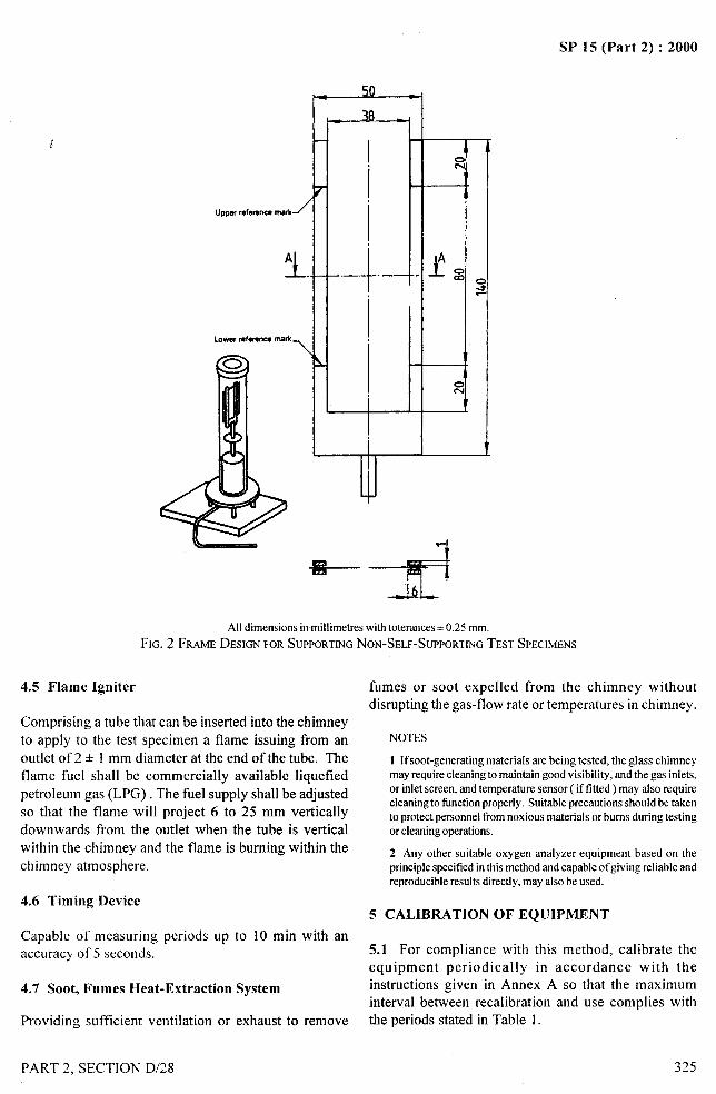
, A
..-.
SP 15 (Part 2) :2000
UPW reference mark1
J_.A
LOww mfOfullcamark\
4.5 Flame Igniter
,●50
2-.
+
JAlldimensionsin millimetreswith toteranccs+ 0.25 mm.
FIG. 2 Fwm DESIGNFORSUPPORTINGNON-SELF-SUPPORTINGTESTSPECIMENS
Comprising a tube that can be inserted into the chimney
to apply to the test specimen a flame issuing from an
outlet of 2 + 1 mm diameter at the end of the tube. Theflame fuel shall be commercially available liquefied
petroleum gas (LPG). The fuel supply shall be adjustedso that the flame will project 6 to 25 mm vertically
downwards from the outlet when the tube is verticalwithin the chimney and the flame is burning within the
chimney atmosphere.
4.6 Timing Device
Capable of measuring periods up to 10 min with anaccuracy of 5 seconds.
4.7 Soot, Fumes Heat-Extraction System
Providing sufficient ventilation or exhaust to remove
PART 2, SECTION D/28
fumes or soot expelled from the chimney withoutdisrupting the gas-flow rate or temperatures in chimney.
NOTES
1 Ifsoot-generating materials are being tested, the glass chimneymay requirecleaningto maintain good visibility, and the gas inlets,or inlet screen, and temperature sensor ( if fitted ) may also requirecleaningto finrctionproperly. Suitable precautionsshould be takento protect personnelfrom noxious materials or bums during testingor cleaningoperations,
2 Any other suitable oxygen analyzer equipment based on theprinciplespecifiedinthis method and capableof giving reliable andreproducibleresults directly,may also be used.
5 CALIBRATION OF EQtJIPMENT
5.1 For compliance with this method, calibrate theequipment periodically in accordance with theinstructions given in Annex A so that the maximuminterval between recalibrationthe periods stated in Table 1.
and use complies with
325
/
.4,-
...-
SP 15 (Part 2) :2000
Table 1 Equipment Calibration Frequencies(Clause 5.1)
Item Maximum Period
Gas-flow rate controls 6 monthsOxygen concentrationcontrols 6 monthsGas systemjoints (as requiredby A-2 in Annex A):
@ forjoints disturbed use or 24 hourscleaning of the apparatus
b) for undistrubedjoints 6 months
6 PREPARATION OF TEST SPECIMENS
B-1/1 ). If the test is not carried out immediately atler
conditioning, place the specimens in a tightly closed
container until the commencement of the test. Each
specimen shall be tested within two minutes of removing
it from either the conditioning atmosphere or the
container.
6.4.2 Testing Atmosphere
Carry out the test in a substantially draught ffee room
or enclosure in an atmosphere of relative humidity
between 20 to 80 percent and temperature between
20 to 35”C.
6.1 Sampling 7 PROCEDURE
Obtain a sample sufficient for preparatio~of 5 to 10 test 7.1 Setting up the Apparatus and Test Specimen
specimens. The sample shall be taken, if relevant, inaccordance with the materials specification or otherwise 7.1.1 Recalibrate equipment components, if necessary
specified. (see 5.1 Annex A).
NOTE— For a material for which the oxygen index is known towithin + 2, 5 test specimens may be sutticient. For materials ofunknown oxygen index, or which exhibit erratic burningcharacteristics, between 8 and 10test specimensmaybe required.
6.2 TestSpecimen Dimensions and Their Preparation
Cut test specimens of size 140+ 5 mm x 52+ 0.5 mm.Ensure that the surfaces of the specimens are clean andfree from flaws that could affect burning behaviour. The
edges of the specimens shall be relatively smooth andfree from furr or burrs of material Ietl from machining.
6.3 Marking of Test Specimens
For monitoring the distance over which a specimenbums, it may be marked with transverse lines at one ormore levels which are dependent upon the specimenform and the ignition procedure to be used. If wet inksare used, the marks shall be dry before the specimen isignited.
6.3.1 The reference marks for testing specimens arecarried by the supporting frame (see Fig. 2).
7.1.2 The test shall be conducted in the testing
atmosphere specified in 6.4.2.
7.1.3 Select an initial concentration of oxygen to be
used. When possible, this may be based on experience
of results for similar materials. Alternatively, try to ignite
a test specimen in air, and note the burning behaviour.
If the specimen burns rapidly, select an initial
concentration of about 18 percent (v/v) of oxygen; if the
test specimen bums gently or unsteadily select an initial
oxygen concentration of about 21 percent (v/v); if the
specimen does not continue to bum in air, select an initial
concentration of at least 25 percent (v/v), depending
upon the difficulty of ignition or the period of burning
before extinguishment in air.
7.1.4 Ensure that the test chimney is vertical (see Fig. 1).
Mount a specimen vertically in the centre of the chimney
so that the top of the specimen is at least 100 mm below
the open top of the chimney and the lowest exposed
part of the specimen is at least 100 mm above the top of
the gas distribution device at the base of the chimney
(see Fig. 1 or Fig. 2 as appropriate).
6.4 Conditioning and Testing Atmospheres 7.1.5 Set the gas mixing and flow controls so that an
oxygenlnitrogen mixture containing the desired
6.4.1 Conditioning concentration of oxygen is flowing through the chimney
at a rate of 40 + 10 mm/s. Allow the gas to flow for atBefore testing, condition the specimens for 24 hours in least 30 seconds to purge the system prior to ignition of
a standard atmosphere of 65 + 2 percent relative each specimen, and maintain the flow without change
humidity and 27+ 2°C temperature (see IS 6359:1971 during ignition and combustion of each specimen. Ignite
‘Method of conditioning of textiles’ given in Section the test specimen as described in 7.2.
.
l“.,
326 PART 2, SECTION D/28
I
I

!*—-
.
SP 15 (Part 2) :2000
I
i
7.1.6 Record the oxygen concentration used as thevolume percent calculated according to the equationsgiven in Annex B.
7.2 Igniting the Test Specimen
7.2.1 Apply the lowest visible part of the flame to thetop of the specimen using a sweeping motion, ifnecessary, to cover the whole surface, but taking carenot to maintain the flame against the vertical faces oredges of the specimen. Apply the flame for up to 30seconds, removing it every 5 seconds for just sufficienttime to observe whether or not the entire top surface ofthe specimen is burning.
7.2.2 Consider the specimen to be ignited, and
commence measurement of the period and distance ofburning, as soon as removal of the igniter, after a contactperiod increment of 5 seconds, reveals, burning
supported by the whole of the top end surface of thespecimen.
7.3 Assessing Burning Behaviour
For the purposes of 7.3.2 to 7.3.4 inclusive, observe
and terminate the burning of individual test specimensas follows.
7.3.1 Commence measurement of the period of burning
as soon as the specimen has been ignited in accordancewith 7.2, as applicable, and observe its burningbehaviour. If burning ceases but spontaneous re-ignitionoccurs in less than 1 second, continue the observationand measurements.
7.3.2 The concentration of oxygen is too high and mustbe reduced if the specimen bums and either the period
or the extent of burning exceeds the relevant limits
specified in Table 2. The concentration oxygen must beraised if the flaming of the specimen extinguishes beforemeeting the criteria specified in Table 2. Do not adjust
the oxygen concentration after igniting the specimen.
Table 2 Criteria for Oxygen Index Measurements
(Clauses 7.3.2 and 7.3.4)
Period of Burning After Extent of BurningIgnition ( Seconds)
180 580 mm below the topof the specimens
NOTE — These criteria do not necessarily produce equivalentoxygen indexresul~ for specimensof differingshapeor testedusingdifierent conditionsor procedures.
7.3.3 Adjust the oxygen concentration, insert a new .
specimen, or if the previous specimen is long enough,turn it end for end or cut off the burnt end, then purge
and re-ignite. ,,...-+‘! “,?
7.3.4 Continue repeating 7.1.5 to 7.3.3 until the critical
concentration of oxygen is determined. This is the lowestoxygen concentration that will meet the criteria specifiedin Table 2. At the next lower concentration that will give
a difference in oxygen index of 0.2 percent or less, thespecimen should not meet the criteria specified inTable 2.
NOTES
1The criticaloxygenconcentrationhas been foundto be dependenton the temperatureof the specimen at ignition and the temperatureof the gas mixture.
2 For a material having consistent burning characteristics, thedifference in oxygen concentration between and extinguishingas specified in 7.3.2 will be reproducible within 0.1 percent to0,3 percent depending on the sensitivity of the flow measuringequipmentandupon the particular oxygen concentration involved.Some materials, however, exhibit erratic burning characteristicsbecauseof inhomogeneity,char formation, dripping, bending, etc,which cause less reproducible results. In such cases, the criticalconceMrationmaybe determined by a statistical testing method asgiven in American Statistical Association Journal, pp-967-970(1965).
7.3.5 Perform the test at least three times by starting ata slightly different flow rate still within 30 to 50 mm/second limits and again performing the procedurefrom 7.1.5 to 7.3.4,
8 CALCULATIONS*
8.1 Calculate the oxygen index, n, of the material foreach replicate in 7.3.5 by the formula:
1000,n=
O,+ N,
where
Oj = the volumetric flow of oxygen in cm3/s, at theconcentration determined in 7.3.4; and
Nz = the corresponding volumetric flow rate ofnitrogen in cm3/s.
NOTE — Ifan oxygenanalyzerisused, the oxygen indexshould bedeterminedusingthe readout fromthe particular instrument used.
8.1.1 If air is used and either oxygen or nitrogen isadded as required, calculate n assuming that air contains20.9 percent oxygen as follows:
n = (100 X 02) + (20.9(0, + N, + /4)
x A):
PART 2, SECTION D/28
I
327
I \,,
I

—
SP 15 (Part 2) :2000
where c)
A = the volumetric flow rate of air in cm3/s. d)
9 TEST REPORTe)
The test report shall include the following:
a) Identification of the material tested, including,where relevant, the type of material, density,previous history, and the specimen orientation o
with respect to any anisotropy inor sample;
b) The test specimen dimensions;
the material
g)
The igniter used;
The individual oxygen index values found foreach of the tests, and average index value;
A description of any relevant ancillarycharacteristics or behaviour, such as charring,dripping, severe shrinkage, erratic burningafter-glow;
Any vari~tions from the requirements of thisstandard; and
Any other information required by the law inforce.
ANNEX A
(Clauses 5.1 and 7.1.1 and Table 1)
CALIBRATION OF EQUIPMENT
A-1 CALIBRATION OF GAS FLOW RATE
CONTROLS
A-1.l Check the system for indicating the gas-flow rate
through the chimney using a water-sealed rotating drum
meter (wet test meter), or an equivalent device, with an
accuracy equivalent to + 2 mm/s flow rate through the, ,
chimney.
A-1.2 Estimate the flow rate by dividing the total gas-
flow rate through the chimney by the cross-sectional
area of the bore of the chimney, for example by using
the equation.
9“
F= 1.27x 10’ D
where
F = the flow rate through the chimney, in mm per
second;
q, = the total gas-flow through the chimney, in litres
per second;
D = the diameter of the bore of the chimney, in
millimeters.
A-2 CALIBRATION OF OXYGEN
CONCENTRATION CONTROLS
A-2.1 Check the concentration of oxygen in the mixture
of gases flowing into the chimney to an accuracy of 0.1percent (v/v ) of mixture, eithqr by sampling the chimney
atmosphere for analysis or by using an independentlycalibrated ‘oxygen analyzer in-situ, integral oxygenanalyzers may be calibrated using standard oxygenl
..
nitrogen mixtures. The checks should be carried out forat least three different nominal concentrations, ~;representating respectively maximum, minimum andintermediate levels for the oxygen concentration rangefor which the equipment is to be used.
A-2.2 Carry out leak-tests on, all joints where leakscould change the oxygen concentration levels inthe chimney from the concentration levels set orindicated.
A-3 CALIBRATION OF COMPLETE EQUIPMENT
A-3.1 Check the performance of the equipment for aspecific test procedure, by testing a calibrated materialand comparing the measured results with the expectedresult for the calibrated material. For information on the ,’
availability and use of calibrated materials, see Annex B.F
/
j~
PART 2, SECTION D/28 1’
I I
II
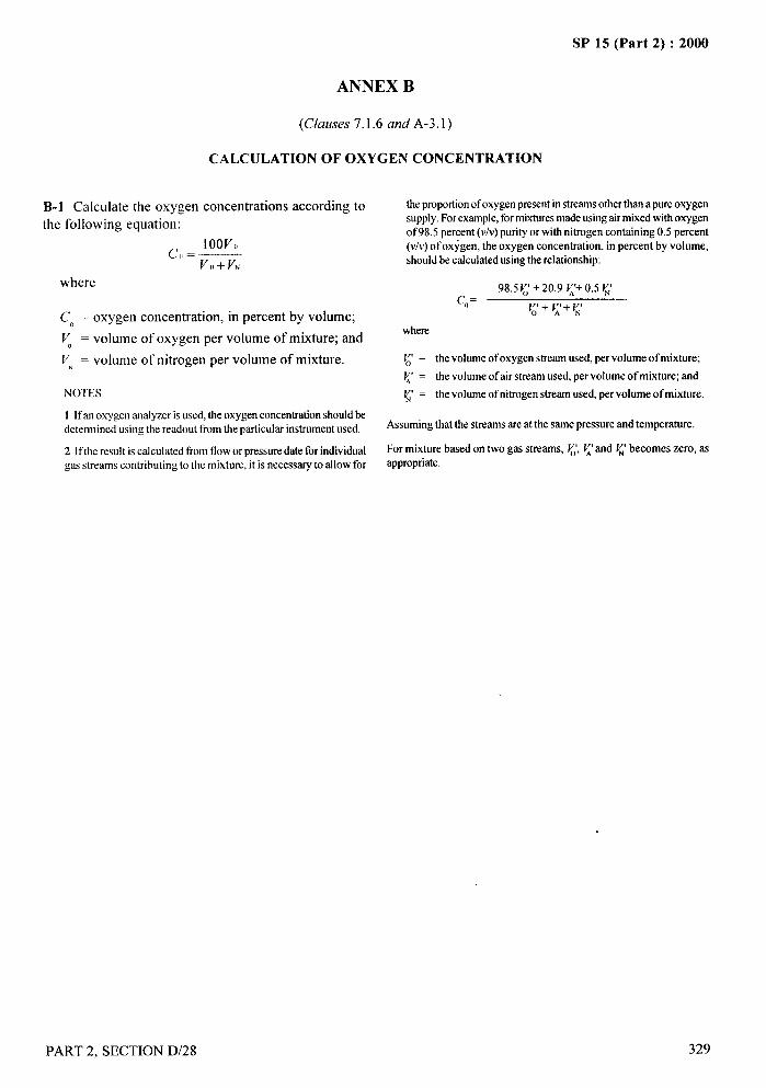
d--
SP 15 (Part 2) :2000.-
ANNEX B
(Clauses 7.1.6 and A-3. 1)
CALCULATION OF OXYGEN CONCENTRATION
B-1 Calculate theoxygen concentrations according tothe following equation:
~,, = 1OOV()
VII+VN
where
CO = oxygen concentration, in percent by volume;
~ = volume of oxygen per volume of mixture; and
V. = volume of nitrogen per volume of mixture.
NOTES
1 If an oxygen analyzer isused,the oxygenconcentrationshouldbedetermined using the readout from the particulm instrumentused.
2 If the result is calculatedfrom flowor pressuredate for individualgas streams contributing to the mixture, it is necessaryto allow for
PART 2, SECTION D/28
the proportionof oxygenpresentin streamsotherthan a pureoxygensupply.Forexample,formixturesmadeusingairmixedwithoxygenof 98.5 percent (v/v)purity or with nitrogen containing 0.5 percent(v/v)of oxygen, the oxygen concentration, in percent by volume,should be calculatedusing the relationship:
the volume of oxygen stream used, per volume of mixture;
the volume of air stream used, per volume of mixture; and
the volume of nitrogenstream used, per volume of mixture.
Assumingthat the streams are at the same pressure and temperature.
For mixture based on two gas streams, ~~,~ and ~ becomes zero, asappropriate.
329
---- 1..,5
SP 15 (Part 2) :2000
DETERMINATION OF THE IGNITABILITY OFUPHOLSTERED COMPOSITES FOR SEATING FOR
FURNITURE BY SMOKERS’ MATERIALS
(hwce : IS 12467: 1988)
The ignitability of upholstered composites for seating for furniture depends to a large extent on the design andmaterials employed in a piece of furniture. The tests carried out on these component materials in isolation may notgive true indication of their behaviour when combined with other component materials in a, piece of furniture.Therefore, to evaluate the ignitability of an item of seating, it is necessary to test the complete finished item offurniture. However, in view of very wide range of designs and materials employed, the method prescribed in thisstandard has been chosen to test upholstery materials combined together to give information regarding the ignitability
properties of assemblies that might be used in number of different circumstances.
The position at which accidentally dropped cigarettes are most likely to cause ignition is the angle between verticaland horizontal surfaces. In this test, for evaluating assemblies of materials, this point has been taken care of, eventhough in practice an assembly might only be used on a single surface. The results, therefore, provide a measureof the ignitability y of a combination of cover and filling which is equally valid for the different designs of furnitureor the different applications in that fimiture in which the combination might be used.
It prescribes a method for examining the ignitability properties of upholstery assemblies when subjected to shoulderingcigarette. Modifications that may be made to examine more specific fiwniture design features are described in Annex A.
The results of this method relate to the behaviour of test specimens as supplied under particular conditions of testand do not take into consideration the effects of ageing, washing, soiling, etc, that may be encountered during thelife of the product. It maybe recognized that this method cannot give a full assessment of tibre properties in allsituations. Measures taken to reduce the ignitability of an assembly may adversely affect other fire properties suchas smoke and toxic gas evolution, and this aspect requires separate consideration.
1 SCOPE
It prescribes a method for assessing the ignitability ofmaterial combinations, for example, covers and filliogused in upholstered seating when subjected to ashouldering cigarette as might be applied accidentallyin the use of upholstered seats. It does not cover ignitioncaused by deliberate acts of vandalism.
2 DEFINITION
For the purpose of this standard, the following definitionshall apply :
2.1 Progressive Stftouldering
An exothermic oxidation not accompanied by flamingwhich is self-propagating, that is, independent of theignition source. It may or may not be accompanied by
incandescence.
NOTE — In practice, it has been found that there isusually a cleardistinctionbetweenmaterialswhichmay charunderthe influeneeofthe ignition source but which do not propagate firrther (non-progressive) and those where shouldering develops in extent andspreads (Progressive).
330
3 PRINCIPLE
An assembly of upholstery material is arranged in
stylized form as a joint between the seat and back (orseat and arm) surfaces of a chair and exposed to an
ignition source of a shouldering cigarette. The
progressive shouldering and flaming of the interior andthe cover of the material is observed and recorded as a
pass or fail result.
4 HEALTH AND SAFETY OF OPERATORS
4.1 General
There is a considerable risk with this test and precautions
have to be taken.
4.2 Enclosure
For safety, the test should be conducted in a suitable
t%me cupboard. If such a cupboard is not available, anenclosure should be constructed so that the tester is not
exposed to the fumes (see 8.1).
PART 2, SECTION D/29
/
I1;1II
SP 15 (Part 2) :2000
4.3 Extinguishers
Accessible means of extinguishing the samples shouldbe provided, for example, a bucket of water, a tireblanket or fire extinguisher.
5 APPARATUS
5.1 Test Rig
A suitable test rig is illustrated in Fig. 1 and 2. It shallconsist of two rectangular frames hinged together andcapable of being locked at right angles to each other.
5.1.1 The frames shall be made from nominal25 mm x 3 mm steel flat bar and shall securely holdexpanded steel platforms set 6 + 1 mm below the topedge of the frames.
NOTE — The size of the mesh of the expanded steel is not criticalbut a mesh size across the diagonals of approximately 28 mm x 6mm has been found suitable.
5.1.2 The internal width and height of the back frameshall be 450 + 2 mm x 300 + 2 mm, and the width and
depth of the base frame shall be 450 + 2 mm x 150+2mm. A standard edging section may be used aroundthe expanded steel to give protection and greater rigidity.
5.1.3 The sides of the frames shall extend beyond theback of each frame to provide for the hinge holes andto form the back legs. The hinge rod shall be of nominal10 mm diameter steel, continuous across the back ofthe rig and its axis 225 + 0.5 mm beyond the backmember of each frame.
5.1.4 The frames shall be lockable at right angles by abolt or pin through each of the pairs of members formingthe back legs. The front legs may be welded across thefront corners of the base frame. The height of the legs
shall be such as to leave a gap not less than 50 mm“high between the base frame and the supporting su$ace.
5.1.5 For the test, rig shall be sited with the enclosure(see 4.2) and the testing shall be performed in asubstantially draught-free environment permitting anadequate supply of air.
5.2 Shouldering Cigarettes Source – An untippedcigarette complying withis needed:
Length
Diameter
Mass
Shouldering rate :
PART 2, SECTION D/29
the following requirements
68 mm approximately
8 mm approximately
1 g nominal
12.0’+ 3.0 min/50 mm
5.2.1 The shouldering rate shall be verified as followson one sample fi-om each batch of 10 cigarettes used :Mark the cigarette, conditioned as described in 6.1 at5 mm and 55 mm from the end to be lit. Light it asdescribed in 8.3.1 and impale it horizontally in draught-free air on a horizontal wire spike inserted not morethan 13 mm into the unlit end. Record the time takento smoulder from the 5 to 55 mm marks.
6 ATMOSPHERE FOR CONDITIONING ANDTESTING
6.1 Conditioning
Before testing, condition the specimen of material tobe tested and the cigarette for 24 h in a standardatmosphere of 65+2 percent relative humidity and27A 2°C temperature (see IS 6359:1971 ‘Method for
conditioning of textiles’ given in Section B-1/1). If thetest is not carried out immediately after conditioning,place the specimen and the cigarette in a tightly closedcontainer until the commencement of the test. Eachspecimen shall be tested within 2 minutes of removingit from either the conditioning atmosphere or thecontainer.
6.2 Testing
Carry out the test in a substantially draught-free roomor enclosure in an atmosphere or relative humiditybetween 20 and 80 percent, and temperature between20 and 35”C.
7 TEST SPECIMENS
7.1 General
The test piece materials shall be representative of thecover, filling and any other components to be used inthe final assembly.
7.2 Cover Material and Fabric Interliner
7.2.1 The cover size needed for each test shall
be 800+ 10 mm x 650 + 10 mm. The long dimensionshall be cut parallel to the selvedges. The cover maybeconstructed from smaller pieces of material providedthat the location of the resulting seams does not occurwithin 100 mm of the area likely to be affected bythe test.
7.2.2 The cover shall have triangular cut-outs 325mm from one end of both sides. The cut outs shall bepositioned such that when assembled on the test rig
331
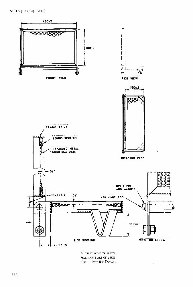
SP 15 (Part 2) :2000
FRONT VIEW
——FRAME 25 x3
/
P..—.—
, EDGING SECTION-
—.——. —/ EXPANDED METAL
: MESH SIZE 28x6
II
1Jj
I
1
_.—SIDE VIEW
P
—. -- —INVERTED PLAN
+6:1
SPL IT—PINAND WASHt?R
\ m--.------Y22*S20*5 621
~–_– —.-—— .—— .
\\\\.b
SIDE SECTION
~-+&22.5t0.5
Alldimensionsin millimetres.
AI.~ PARTSAREOF STEEL
FIG. 1 TEST RIG DETAIL
—._ —..VIEW ON ARROW
—-.-,
[
332
/
I
i’1
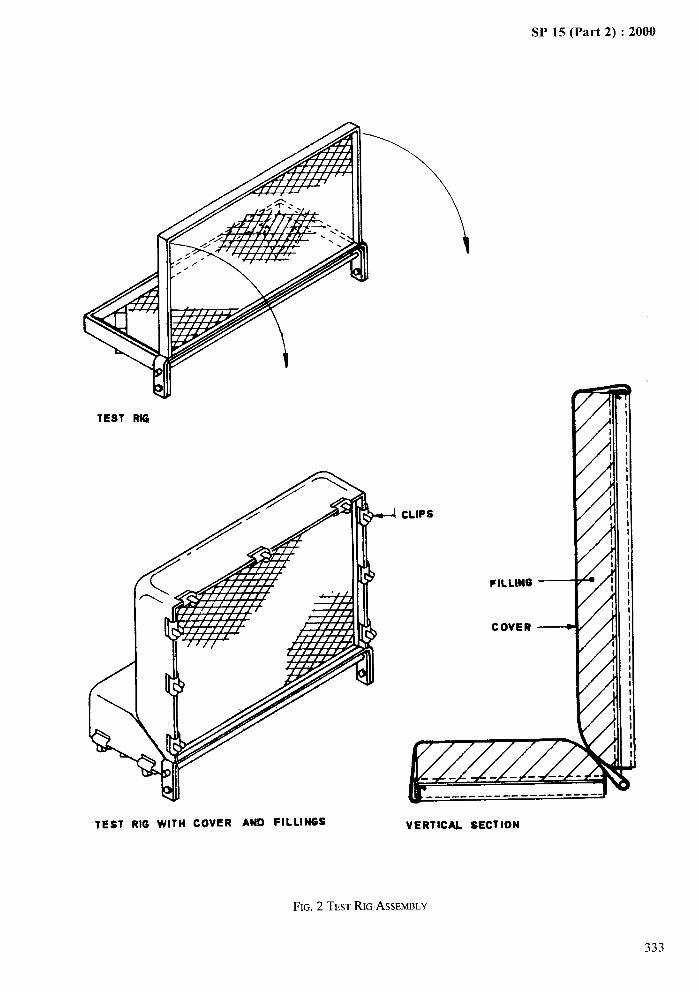
4—.....4A
SP 15 (Part 2) :2000—
I
wTEST RIG
-i CLIPS
wTEST RIG WITH COVER AND FILLINGS VERTICAL SECTION
FIG. 2 TEST RIG ASSEMBLY
333
1’ I
1
SP 15 (Part 2) :2000
the lie of any pile is down the back assembly and fromthe hinge to the front of the base frame. The size ofthese cut-outs shall be approximately 50 mm base and110 mm high. Where a fabric interliner is used, itshall be cut to the same dimensions and in the sameorientation as the cover for fitting to the test rig underthe cover.
7.3 Upholstery Filling
Two pieces, one 450 * 5 mm x 300& 5 mm x 75 + 2
8.3 Procedure
8.3.1 Light a cigarette (see 5.2) and draw air throughit until the tip glows brightly. Not more than”8 mm ofthe cigarette shall be consumed in this operation.
8.3.2 Place the shouldering cigarette in position alongthe junction between the vertical and horizontal testpieces, allowing at least 50 mm from the nearest sideedge, or from any marks left by previous test, to thecigarette and simultaneously start the clock.
mm thick, and the other 450 + 5 mm x 150 + 5 mm x75 + 2 mm thick shall be used for each test.
8.3.3 Observe the progress of combustion and recordany evidence of progressive shouldering (see 2.1) or
7.3.1 Some cushioning assemblies may consist offlaming in the interior and/or cover.
several layers that may be typically felt, wadding or NOTE — The detection of smorddering may be difficult and isdifferent foams. In these cases, the test pieces shall eased by watching for smoke emerging at points at a distance ftom
reproduce the upper 75 mm of the cushioning assembly. the cigarette. Smoke is most easily viewed by looking down arising column by means of a mirror.
7.3.2 Where the tilling is less than 75 mm thick, the 8.3.4 If progressive shouldering or if flaming of thetest piece shall be built up to the required thickness byadding to the underside a fi,uther layer of the bottom
upholstery components is observed at any time withina period of one hour of the placement of the cigarette,
material.extinguish the test piece and record a failed result for
8 TEST PROCEDUREthe shouldering cigarette test.
8.3.5 If progressive shouldering or if flaming is not8.1 Warning observed within the one hour period or if the cigarette
fails to smoulder its complete length, repeat the testFor safety, all tests should be carried out in a suitably with a new cigarette placed in. a fresh position not lessconstructed fume enclosure (see 4.2). than 50 mm from any previous test damage. If
progressive shouldering or if flaming is not observed8.2 Preparation in this retest or if the cigarette fails to smoulder its
complete length, record a pass result for the shouldering
8.2.1 Ensure that the means of extinguishing are close cigarette test, unless the test piece fails the final
to hand (see 4.3). examination specified in 8.4. Otherwise extinguish thetest piece and record a failed result.
8.2.2 Open out the test rig and thread the coveringfabric and, if any, the fabric interliner behind the hinge NOTE— The repeat test maybe run concurrently with the last
bar.test (see 8.4).
8.2.3 Place the filling pieces under the covering fabricand, if any, the fabric interline locating the fillingpieces in the frame recesses, and allowingapproximately 20 mm of fabric to wrap round the insideof the fi-ames.
8.2.4 Lock the frames at right angles by the bolts orpins ensuring that the filling components are not
displaced.
8.4 Final Examination
Immediately after completion of the test programme
on the assembly dismantle and examine it internallyfor progressive shouldering. If this is present,extinguish the test piece and record a failed result forthe relevant test source. For safety reasons, ensure thatall shouldering has ceased before the rig is leftunattended.
9 REPORT
8.2,5 Fasten the fabric over the top, bottom and sidesof the frame using clips and ensure that the fabric(s) is
9.1 The report shall include the following:
secured and under even tension. a) The following test result relate only to the
.
334 PART 2, SECTION D/29
I1,I
b)
c)d)
ignitability of the combination of materialsunder the particular conditions of test; theyare not intended as a means of assessing thefill potential fire hazard of the material in use:
The identification and construction of the testsamples;
The test result, pass or fail; andThe name, initials or tade-mark of themanufacturer.
-. .+SP 15 (Part 2) :2000
9.2 The report shall contain details of any features of -- ~the test pieces or procedures that may have affected theresults. Such features are: 1
a)
b)
c)
ANNEX A
GUIDELINES FOR DESIGNERS
A-1 This test method prescribes method for examiningthe ignitability, in defined circumstances, of an assemblyof upholstery materials. These materials are combinedtogether in a way intended to be generally representativeof their end use in upholstered seating, and the ignitionsource is a shouldering cigarette. Thus the potentialignitability of using a particular cover, filling andinterline in combination can be assessed and this willallow the development of specifications concerned withignition by smokers’ materials. However, there are twoimportant limitations, as follows:
a) The test is concerned only with ignitability,and any controls of fire hazard have toconsider, in addition, other aspects of fireperformance such as rate of fire developmentheat output, rate and quantity of smokeproduction, and toxic gas evolution. Ideally,any attempts to reduce ignitability ought notto affect these other properties adversely.
b) The tests only measure the ignitability of acombination of materials used in upholsteredseating and not of a particular finished itemof furniture incorporating these materials.They give an indication of, but can not
guarantee, the ignition behaviour of thefinished item of furniture. This limitationoccurs because design features of the firniturecan greatly affect its fire properties; anyignitability tests of a piece of firniture wouldtherefore need to be carried out on the actualitem and not on component materials or mock-ups. However, limited information on
Conditioning of the test sample; ,W...*
Special features of burning, for example, 1:4
melting, drippings, charring and development \
of flames from shouldering; and
Times of major events, for example, ignition oftest pieces, cover splitting and extinction.
AND SPECIFIERS
ignitability more specifically related to anintended design may be obtained as indicatedin A-2 and A-3.
A-2 This test method prescribes laboratory test of an
assembly of materials which will give general guidanceon the ignitability of finished furniture, but where more
specific information is required, or in critical areas ofend use, the principles may be applied to complete items
or components of fi.nmiture or to suitable modified testassemblies, some examples of which are given below.In such cases the source described in 5.2 maybe appliedat positions which, as a general rule, correspond to those
where the hazard of ignition occurs in use: i
Example 1 – If a chair were to have a gap betweenthe seat and back cushions, the placement of
ignition source in the angle of the tests apparatuswould be inappropriate. Instead, face ignition,where the sources are placed at the centre of the
horizontal and vertical surfaces, would be moremeaningful.
Example 2 – The test apparatus may be used to
model the junction of any vertical and horizontalsurfaces so that both arm and back constructions if
different, may be tested separately in conjunction
with the seat.
Example 3 – The use of diferent materials in a back
and seat of chair may be reproduced in the test,two different cover fabrics being joined by sewingor staples behind the hinge bar.
PART 2, SECTION D/29
/
335
i!,
I
SP 15 (Part 2) :2000i
Example 4 – lf in the final design a loose cushionis to be placed on an upholstered seat platform,
additional cigarette traps are produced between the
loose cushion and the surrounding upholstery. Thismay be examined by using the larger test rig and
test pieces by constructing a loose cushion of the
appropriate materials measuring 500 + 5 mm x
750 * 2 mm to be placed on top of the horizontalsurface of the normally assembled test arrangement.
A-3 Another way in which this principle might be used
336
is to give information about individual materials to beused in a combination. For example, the ability of a
cover material to provide protection against ignition can
be indicated by testing it in combination with a substrateof known flammability; standard non-flame retardant
flexible polyether foam with a density of about
22 kg/m~ has been found to be suitable. Such informationabout the individual materials does not eliminate the
need to test the actual combination, but it can help in
the short listing of material combinations and so reducethe over all amount of testing required.
PART 2, SECTION D/29
i-- --!
1r,

SP 15 (Part 2) :2000
EVALUATING THE RELATIVE EFFICIENCY OFWETTING AGENTS FOR MERCERIZATION
(hurce: IS 5151: 1969)
To facilitate uniform, thorough and speedy impregnation of textile materials which is much desired in mercerizing,wetting agents are extensively used. From among the varieties of commercial wetting agents, the textile processorhas to choose the one suitable for his requirements. This test method is used to assess the relative efficiency ofwetting agents.
1 SCOPE
This standard prescribes two methods for evaluating therelative efficiency of wetting agents used in themercerization of cotton textiles.
2 PRINCIPLE
In the first method the time required for complete wettingof a bundle of yam of canvas disc in caustic soda solutioncontaining the wetting agent is determined. For the sameconcentration of different wetting agents, lesser thewetting time, higher is the efficiency of wetting agent.h-rthe second method, a single cotton thread is allowed
to contract in caustic soda solution containing thewetting agent for definite time and the contraction isdetermined. Higher the contraction, more efficient isthe corresponding wetting agent.
3 REAGENTS
3.1 Quality of Reagents
Unless specified otherwise pure chemicals shall beemployed in tests and distilled water shall be used wherethe use of water as reagent is intended.
NOTE — ‘Purechemicals’shallmean chemicalsthat do not containimpuritieswhich affectthe test results.
3.2 Caustic Soda Solution – 300 g/1.
NOTE — The solution should be allowed to stand and supernatantclear solution be used.
4 FIRST METHOD
4.1 Apparatus and Materials
4.1.1 Beakers or Glass Jars – of 600 ml capacity.
4.1.2 Measuring Pipettes – graduated in 0.05 ml.
4.1.3 Measuring Flask – of 500 ml capacity.
PART 2, SECTION D/30
4.1.4 Stop-watch – to read correct to one-tenth of asecond.
4.1.5 A Special Holding Device – made of stiff stainlesssteel wire with a coil about 50 mm in diameter at oneend and a hook in the centre of the coil to hold the testspecimen (see Fig. 1).
4.1.6 Cotton Yarn or Cotton Canvas
Cotton Yarn – grey, unboiled, 15 tex x 2 (or 40s/2)combed, long staple.
Cotton canvas – grey, unboiled, 615 g per mz.
4.2 Preparation of Test Specimens
4.2.1 From the grey cotton yam, cut out the required
number of bundles, each containing 160 parallel ends,25 mm in length. In case of canvas, cut out the requirednumber of test specimens of size 25 mm x 25 mm withthe help of a die. Alternatively, prepare test specimensof 25 mm diameter.
NOTES1 The cotton yarns maybe tied by single thread of the same quality(see 4.1.6) to form the bundle.2 The square pieces may be cut with sharp pair of scissors.Precautions should be taken that there are not frayed ends.
4.3 Procedure
4.3.1 Take a 600-ml beaker or glass jar. Pour 500 ml ofcaustic soda solution at 27 + 2°C. Pipette out 3.75 mlof one of the wetting agents (see Note 1) under test.Stir the contents until the wetting agent is dissolvedcompletely in caustic soda solution (see Note 2). Allowthe solution to stand until all air bubbles have risen tothe surface.
NOTES
1It ispresumedthatthemercerizingwettingagentsaremostlyliquids.
2 It is otten better to mix the wetting agent thoroughly with smallvolumeof the causticsoda solutionbeforeadding this to the bulk of
337

SP 15 (Part 2) :2000
,the mercerizing solution. It should be particularly noticed whether 4.7 Plot a graph showing the average sinking timethe wetting agent remainswell dispersedor dissolvedbecauseseparationofanimmisciblelayeronthesurfacewouldentirelyvitiate against the corresponding concentrations of wetting
theresultsandgivefalsevalues. agents in ml per 500 ml of caustic soda solution.
Similarly, plot the graphs for the other wetting agents
under test on the same graph paper.
4.8 From the graphs obtained as in 4.7, determine the
wetting time for each wetting agent under test for specific
concentration, say,, 5.00 ml of wetting agent.
4.9 Compare the results to determine the relative
wetting power of the wetting agents under test bearing
in mind that lesser the wetting time, the higher is the
efficiency of the wetting agent.
5 SECOND METHOD
5.1 Apparatus and Materials
5.1.1 A 50-ml graduated burette in 0.1 ml with a two
way stopcock and a side arm – the side arm being
connected to a reservoir.
FIG. 1 APPARATUSFORDETERMINATIONOF WErTING TIME 5.1.2 A Stop-Watch
4.4 In case of yam drop one bundle carefully on thesurface of caustic soda solution. Start the stop-watchand note the time required for complete wetting of allthe ends.
And in case of canvas attach a loop of thick sewingthread about 100 mm in perimeter to one corner of thetest specimen. Attach the specimen through the loop tothe wire holder. Hold the wire holder with one hand
and the test specimen with the other. Immerse the testspecimen in caustic soda solution gently such that thespecimen remains upright in the solution and the threadof the loop is also straight (see Fig. 1). Start the stop-
watch. Note the time required for the specimen to sinkas indicated by limping of the thread.
4.5 Repeat the test (see 4.4) for four times for the sameconcentration of the wetting agent and calculate theaverage sinking time.
4.6 Repeat the test (see 4.4 and 4.5) with differentconcentrations of wetting agents, say, by adding 5.00ml and 6.25 ml each time instead of3.75 ml of wettingagent in caustic soda solution, and calculate the averagesinking time for each concentration separately.
NOTE — If the Imercwizingagent to be tested is too efficientor tooineticient to obtain comparison within the range of the volumesalready employed then either smaller (1.25 ml, 2.50 ml) or larger(10,00 ml, 12,50ml) volumes oftbe pmdqct should be tested.
To read correct to one-tenth of a second.
5.1.3 Cotton Yarn
Grey, unboiled 15 tex x 2 ( or 40s/2) combed, long staple
cotton.
5.2 Procedure
5.2.1 To one end of the cotton yam tie a one-gram
weight. Adjust the yarn in such a way that the knot
tied on the weight coincides with the 50-ml mark of
the burette. The other end of the yam is fitted above
the burette in such a way that the yarn is in the central
position (see Fig. 2). Prepare separately solutions
containing four different concentrations of the wetting
agent under test. Draw into the burette 50 ml of the
solution from the reservoir and start the stop-watch when
the level of the solution reaches the zero mark. Observe
the contraction in one minute (see Notes under 4.3.1).
5.2.2 Repeat the test for nine times for the same
concentration of wetting agent in the solution. Calculate
the average of the ten determinations.
5.2.3 Calculate percentage contraction as follows:
Difference in burette readingx 100
50
338 PART 2, SECTION D/30
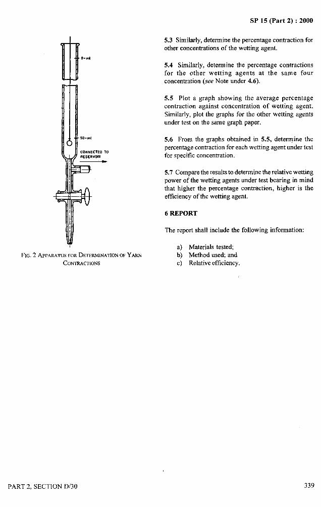
. ,4-—
111110-ml
I
FIG. 2 APPARATUSFORDETERMINATIONOFYARNCONTRACTIONS
SP 15 (Part 2) :2000
5.3 Similarly, determine the percentage contraction forother concentrations of the wetting agent.
.,5.4 Similarly, determine the percentage contractions !
,.-,.-.+,,‘!
for the other wetting agents at the same fourconcentration (see Note under 4.6).
5.5 Plot a graph showing the average percentagecontraction against concentration of wetting agent.Similarly, plot the graphs for the other wetting agentsunder test on the same graph paper.
5.6 From the graphs obtained in 5.5, determine thepercentage contraction for each wetting agent under testfor specific concentration.
5.7 Compare the results to determine the relative wettingpower of the wetting agents under test bearing in mindthat higher the percentage contraction, higher is theefficiency of the wetting agent.
6 REPORT
The report shall include the following information:
a) Materials tested;b) Method use~ andc) Relative efficiency.
PART 2. SECTION D/30 339
SP 15 (Part 2) :2000
METHODS OF TEST FOR
COATED AND TREATED FABRICS
PART 1 DETERMINATION OF ROLL CHARACTERISTICS
[Source : 1S 7016 (Part 1) : 1982]
Coated and treated fabrics are normally sold in the roll form. It, therefore, becomes essential to find out the correctlength, width and thickness of the rolls of fabric before accepting the supply. Further, the mass per unit area of thecoated and treated fabric, base fabric and of the coating are important requirements of contract for such fabrics.Determination of all these characteristics are collectively called the roll characteristics.
1 SCOPE
It describes the methods for determining the length,width, net mass, mass per unit area, and thickness ofrolls of coated and treated fabrics, with the exception ofknitted type fabrics.
NC)TE— It shoLIILI bc noted that the roll cannot normally beconditioned in a standardatmosphereand,therefore,the resultsmaybe inthleoccdbyvariationofmoistore doeto changesin atmosphericconditions.
2 DETERMINATION OF THE LENGTH OF AROLL
2.1 General Method
2.1.1 Apparatus
Flat table, not less than 5 m long, and at least as wide asthe roll to be tested. Both longitudinal edges of the tableshould be marked off in 1 m lengths, at least one ofthese lengths being subdivided into 10 mm divisions.
2.1.2 Procedure
Trim the cut end of roll, if necessary, so that it is atright angles to the warp (longitudinal) direction of the
roll, such trimming being confined to the minimumwhich is necessary to effect this. With the cut end ofthe roll aligned with the zero mark on the table, unrollthe material along the table so that no tension isintroduced. On reaching the limit of the table, markthe back of the roll by some suitable method on bothedges to coincide with a known division of length.Reroll the portion that has been measured. Lay out,free from tension, a fullher portion of the unmeasuredlength and measure from the marked edges, as before.Repeat this process until the end of the roll is reached,trimming this, if necessary, as before. Measure the finallength to the nearest 50 mm.
340
2.1.3 Expression or Results
Report the length of the roll, in metres, as the sum of allthe readings, adjusted to the nearest 50 mm.
2.2 Drum Method
2.2.1 Procedure
Run the coated fabric over a measuring drum with just
enough uniform tension to keep it running flat and true.Determine the length from the dial or counter on thedrum. Report the length of the roll in metres, adjustedto the nearest 50 mm.
3 DETERMINATION OF THE WIDTH OF A ROLL
3.1 Apparatus
3.1.1 Flat Table – not less than 2 m long, and at least50 mm wider than the width of the roll to be tested.
3.1.2 Steel Scale – length shall be greater than the widthof the roll to be measured, graduated in centimetres andmillimetres.
3.2 Procedure
Unroll the material along the table so that it is laid outsmoothly without tension in either direction. In case offabrics coated on one side, the coated side shall be keptupwards. Record to the nearest 5 mm at least fivedifferent measurements of width uniformly distributedalong the full length of the roll or piece.
3.3 Expression of Results
Calculate the mean of the recorded widths adjusted tonearest 5 mm and report the value obtained as theaverage usable width. Report also the minimum usable.width recorded.
PART 2, SECTION D/31.1

SP 15 (Part 2) :2000
4 DETERMINATION OF THE NET MASS ANDMASS PER UNIT AREA OF ROLL OR SAMPLE
4.1 Determination of the Net Mass Per Unit Area ofa Roll
4.1.1 Apparatus
Weighing device, with a calibrated scale, accurate atfull scale deflection to 0.10 percent.
4.1.2 Pt-ocedure
Place the roll of material centrally on the pan or othersupporting arrangement of the weighing device. Ensurethat the roll and its support are free of contact with otherbodies. Determine and record the gross mass. Determineand record the mass of the tube or former upon whichthe material has been rolled, and deduct this from thegross mass. Record the value thus obtained as the netmass. Determine the length and width of the roll inaccordance with the procedure given in 2 and 3, andcalculate the mass per unit area in grams per squaremetre to the nearest 5 g/m2.
4.1.3 Expression ofl?esu[ts
to agreement between the purchaser and the supplier,the conditioning time may be curtailed to 24 hours. Forall test purposes, the minimum time betweenvulcanization or curing and testing shall be 16 hours.Whenever possible, the time between vulcanization orcuring and testing should not exceed three months. Inother cases, tests, shall be made withing two months ofthe date of receipt by the customer of the product.
4.2.2.3 Weigh the test pieces to the nearest 0.005 g,and calculate the mass per unit area in grams per squarem etre.
4.2.3 Expression of Results
The mass per unit area should be expressed as theaverage of the calculated values in grams per squaremetre, adjusted to nearest 5g/m2.
NOTE — ‘Meprocedure given io 4.2.2 is intended for ose when asmallsampleissentto tbe laboratoryfortest, The result is consideredapplicable to the sample, but not to the piece or lot of goods fromwbicb the sample was taken, anless the number of samples andmethodsare agreedby those concerned.If this is done, each sampleshouldbe testedin accordancewith the proceduregiven in 4,2.2 andtbe resaltsaveragedto obtainthe averagemassper unit area in gramsper squaremetre,
The net mass should be expressed in kilograms to the 4.3 Determination of the Mass Per Unit Area of the
Base Fabricnearest O.10 kg. The mass per unit area should beexpressed in grams per square metre to the nearest5 glm~. 4.3.1 Apparatus
4.2 Determination of the Mass Per Unit Area of a
Sample
4.2.1 Test Piece
The test piece shall be square, rectangular or circular inform, and have an area of 10000 + 100 mm2.
4.2.2 Procedure
4.2.2.1 Cut from the sample three test pieces, one fromthe centre, and the other two symmetrical with the first,in such a manner that their external edge is between 50and 150 mm from the selvedge of the sample taken alonga line which makes an angle of 45° with the length ofthe roll. Designate these test pieces A, B and Crespectively.
4.2.2.2 Comiitioning
Condition the test pieces at 27 + 2°C and 65 * 2 percentrelative humidity for 48 hours prior to testing. Subject
4.3.1.1 Balance – accurate to 0.005 g,
4.3.1.2 Flask – 500 ml capacity, fitted with a refluxcondenser.
4.3.1.3 Water-bath
4.3.1.4 Oven – with natural air circulation.
4.3.2 Test Piece – The test piece shall be a square orrectangle, having an area of 10000 + 100 mmz.
4.3.3 Procedure
4.3.3.1 Cut from the sample three test pieces, one fromthe centre, and the other two, symmetrical with the first,in such a manner that their external edge is between 50and 150 mm from the selvedge of the sample taken alonga line which makes an angle of 45° with the length ofthe roll. Designate these test pieces, A, B and Crespectively. Immerse each test piece separately in 150ml of an appropriate solvent or swelling agent. Decant
PART 2, SECTION D/3 1.1 341
J
.—..-.
SP 15 (Part 2) :2000
and remove where possible the bulk of the coating from 5 DETERMINATION OF THICKNESSthe base fabric. In case extraction is not sufficient,refluxing for 30 minutes may be done. Immerse again 5.1 Apparatusfor 30 minutes, using fresh solvent, and decant.Thereafter, immerse the fabric and any loose threads in 5.1.1 GaugeI 50 ml of solvent, with occasional agitation for 30minutes at room temperature. Remove the stripped test The gauge shall be of dead weight type, equipped withpieces, together with any loose threads, from the solvent a dial graduated to read directly to 0.02 mm. The presserand wash them in 100 ml of acetone. Dry the test pieces foot should be circular having a diameter of 9.5 +for one hour at a temperature of approximately IOO”C. 002mm or 5(I + 0.05 mm. The presser foot and
4.3.3.2 Condition the stripped test pieces for 24 hoursat 27 + 2°C and 65 + 2 percent relative humidity, andweigh to the nearest 0.005 g.
4.3.3.3 Wash the stripped test pieces with a furtherquantity of the appropriate solvent in the mannerindicated, wash in acetone, dry and condition and weigh
them, as before. If the second weighing differs from thefirst by more than 1 percent, repeat the solvent treatmentuntil the difference is less than 1 percent. Use the finalmass for calculating the mass per unit area of the fabric.
connected moving parts shall be loaded to give the
pressure according to the category of articles being
measured. The presser foot and anvil surfaces shall beplane to within 0.002 mm, and parallel to one another
to within 0.002 mm. The gauge shall be calibrated forthe actual load exerted by the presser foot by means of
any device so arranged to measure the total force exerted
by the presser foot at the several gauge readings orpresser foot levels selected for calibration. The presser
foot shall be brought to each calibration level from a
higher one:
4.3.4 Expression of Results Pressure
The mass per unit area of the fabric shall be expressed a) Ordinary articles 24 KN/m2*as the mean value obtained from the three results in b) Articles sensitive 10 KN/m2*grams per square metre to the nearest 5 g/mz. to pressure
NOTESI The method is not valid forfabricswhich aresolubleinthe solvent 5.2 Procedureustd for the test.2 The mass ot’thefabricatkr removingthe coatingmaybe different 5.2.1 Measure the thickness on an oblique line drawnfrom that of the original fabric.
at an angle of 45° to the length of the roll preferably at
4.4 Determination of the Mass Per Unit Area of thea distance of about 1.m from the end of the roll. On this
Coatingline, make five evenly distributed measurements, thefirst being taken at a position between 50 and 150 mm
4.4.1 Procedure from the selvedge. -
It is expedient to consider the mass per unit area of the 5.2.2 Place the coated fabric on the anvil of the gauge,
coating as the difference between the mass per unit area smoothen it but without tension. Lower the presser foot
of the coated fabric and the mass per unit area of the into the material (without impact), allow it to rest for
base fabric. From the mass per unit area of the coated 10, seconds and observe and record the reading of the
fabric (determined according to 4.2) subtract the mass dial.
per unit area of the base fabric for the correspondingtest piece (determined according to 4.3). 5.3 Expression of Results
4.4.2 Expression of Results Express the results in millimetres. The mean linearthickness in millimetres is the arithmetic mean of the
The mass per unit area of the coating shall be expressed five measured values on the same oblique line.
in grams per square metre as the mean of the three valuesfound in acordance with the procedure given in 4.4.1. * 1kgf/Cm2= 98.07 KN/m2.
---
!!$
342 PART 2, SECTION D/31.1
II!!
I
SP 15 (Part 2) :2000
METHODS OF TEST FOR COATED AND TREATED FABRICS
PART 2 DETERMINATION OF BREAKING STRENGTH AND EXTENSION AT BREAK
[Source : 1S 7016 (Part 2) : 1981]
The strength value determined when a specimen of textile fabric or coated fabric is tested to breaking is not a fixedquantity; it depends on the width and length of the specimen, on its moisture content, temperature and on the speedat which the breaking load is reached. In addition to real changes in specimen strength, errors in observed valuecan occur through errors of the testing machke and its operation. The testing machine is accurate under static orslow moving conditions, but not so in the case of very rapidly applied load. Failure to grip the whole width ofspecimens leads to partial slip and to less than the fair estimate of strength. At present, therefore, the concept ofbreaking strength of a coated and treated fabric is an empirical approximation under one-way stretch conditions to
r the biaxial strength shown by the fabric in actual service. For the sake of general agreement on quality assessment
I it has become necessary to standardize most of the conditions under which breaking strength of base fabrics should
be tested, and as far as possible similar conditions are desirable for coated fabrics.
1 SCOPE
1.1 [t covers methods of test for determination ofbreaking strength and extension at break using thefollowing types of machines:
a) Constant rate of load,b) Constant rate of traverse, andc) Constant rate of specimen extension.
1.1.1 This method is not suitable for use with productsof which base cloth is of mesh construction or withknit fabrics.
2 APPARATUS
2.1 Tensile Testing Machine
All tensile lnachines shall be provided with means forindicating or preferably for recording both the maximumload applied to the specimen in stretching it to ruptureand the corresponding extension of the specimen.Alternatively any other Imeans to measure extension maybe used. LJnder the conditions of use, the error of theindicated or recorded maximum load at any point in the
range in which the machine is used shall not exceed+ I percent of the load, and the error of the indicated or
recorded maximum jaw separation shall not exceed 1mm. The central points of the two jaws of the machineshall be in the line of pull, the front edges shall beperpendicular to the line of pull, and their clampingfaces shall be in the same plant. The jaws shall be capableof holding the specimen without allowing it to slip, shallbe so designed that they do not cut or otherwise weakenthe specimen. and shall be wider than the test specimen.The faces of the jaws should preferably be smooth and
PART 2, SECTION D/3 1.2
flat, but when the specimens cannot be satisfactorily heldwith flat-faced jaws even with packing, engraved orcorrugated jaws may be used.
NOTE — Piecesof feltapproximately3 mm thick have been foundto be suitablefor packing,but the choiceof type ofjtrwsand packingshould be that combination which gives the highest breaking loadand doesnot causean onduenumberof breaks in close proximity tothe edgesof thejaws. Suitablepackhg materials for use with eithersmooth or corrugatedjaws include paper, felt, leather, plastics orrubbersheets.
2.1.1 Constant-Rate-of-Load Machines
Afier the first 10 seconds of the test, the average rate ofincrease of load in any two seconds interval shall notdiffer by more than 25 percent from the average rate ofincrease of load over the whole period of the test.
The machine shall apply the required load within60+ 10 seconds. The required load shall be the specifiedminimum breaking load or, when the minimum breakingload is not specified, the average breaking load asestimated from preliminary experiments.
2.1.2 Constant-Rate-or- Traverse Machines
After the first five seconds of the test, the average rateof traverse of the pulling jaw in any two seconds intervalshall not differ by more than 5 percent from the averagerate of traverse over the whole period of the test. Therate of traverse of the pulling jaw shall be 100+ 10 mm/min.
2.1.3 Constant-Rate-o f-Extensiorr Machines
For machines in which the rate of separation of theclamps is independent of the extensibility of material
343
.,, &
SP 15 (Part 2) :2000..—-.. .—
under test, the rate of traverse of the pulling jaw shall
be such that rupture is reached in 60+ 10 seconds.
3 TIME LAPSE BETWEEN MANUFACTURE
AND TESTING
3.1 For all test purposes the minimum time betweenmanufacture and testing shall be 16 hours, in order to
ensure that the material attains dimensional stability
due to stress relaxation.
3.2 In order to bind the user and supplier to a stipulated
time for carrying out conformity test for supplied
material, the following shall apply.
3.2.1 For non product test separate test piece is requiredfor testing. Therefore, the maximum time between the
manufacture and testing shall be eight weeks and for
evaluation intended to be comparable, the tests as far aspossible, should be carried out after the same time
interval.
3.2.2 For product test, whenever possible the time
between manufacture and testing should not exceed sixmonths. In other cases tests shall be made within four
months of the date of the receipt of the product by the
customer.
4 TEST PIECES
4.1 From the sample, cut test pieces of coated and treated
fabric 50+ 0.5 mm wide and of convenient length so as
to permit a free length of 200 mm between the jaws.
Five test pieces shall be cut with the length parallel to
the warp threads and five test pieces with the length
parallel to the weft thread. In case of difficulty, establish
the direction of the warp thread by tearing and then cuttest pieces parallel to this direction. Select test pieces
fairly evenly spaced over the full usable length and width
of the sample avoiding the selvedge so that no two test
pieces contain the same warp threads or weft threads asthe case may be.
5 CONDITIONING
5.1 Conditioning
Condition the test pieces at 27 + 2°C and 65 + 2 percentrelative humidity for 48 hours prior to testing.
344
6 PROCEDURE
6.1 Set the jaws of the testing machine 200 + 1 mmapart. Clamp a test piece centrally in the jaws so thatits longitudinal centre line passes through the centredpoints of the front edges of the grips. Apply theappropriate pre-tension from the following values:
RecommendedPre-tension
a) For fabrics up to and 2Nincluding 200 g/m2
b) For fabrics over 200 and up to and 5Nincluding 500 g/m2
c) For fabrics over 500 g/m2 10N
6.2 Engage any device for reading the breaking loadand elongation, put the moving clamp in motion andextend the test piece to the point of rupture under theconditions appropriate for the type of machine beingused as specified in 3. Repeat the procedure for eachtest piece.
NOTE — Ifanytest piecebreakswithin 10mm of line of contactofeither of thejaws, recordthe resul~ but if it is found to have brokenat a load less than 75 percent of the average of the remainder of thespecimensdo not use it in calculatingthe breakingload.Test anotherspecimen.
7 EXPRESSION OF RESULTS
7.1 Breaking Load
Calculate the mean of the five results for breaking loadfor each direction and report the values obtained asbreaking load in N/50 mm width stating the methodused.
7.2 Extension at Break
Calculate the mean of the five results in each directionand express this as a percentage of the initial gaugelength as follows:
Extension at break, _ Increase in gauge length ~ ~w—percent Original gauge length
PART 2, SECTION D/3 1.2
“
i?
I‘1 ‘“.)’;
,:
,,
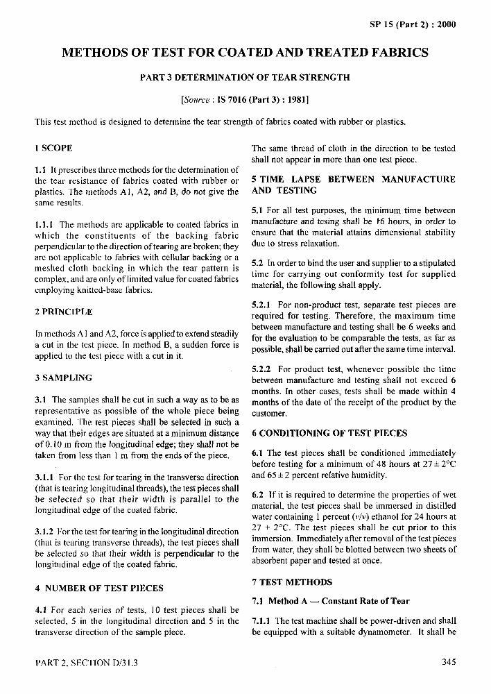
II
SP 15 (Part 2) :2000
OF TEST FOR COATED AND TREATED FABRICS
PART 3 DETERMINATION OF TEAR STRENGTH
[Source : IS 7016 (Part 3) : 1981]
This test method is designed to determine the tear strength of fabrics coated with rubber or plastics.
1 SCOPE
1.1 Itprescribes three methods forthedeterrninationofthe tear resistance of fabrics coated with rubber orplastics. The methods A 1, A2, and B, do not give thesame results.
1.1.1 The methods are applicable to coated fabrics inwhich the constituents of the backing fabricperpendicular to the direction of tearing are broken; theyare not applicable to fabrics with cellular backing or ameshed cloth backing in which the tear pattern iscomplex, and are only of limited value for coated fabricsemploying knitted-base fabrics.
2 PRINCIPLE
[n methods A 1and A2, force is applied to extend steadilya cut in the test piece. In method B, a sudden force isapplied to the test piece with a cut in it.
3 SAMPLING
3.1 The samples shall be cut in such a way as to be asrepresentative as possible of the whole piece being
examined. The test pieces shall be selected in such away that their edges are situated at a minimum distanceof 0.10 m from the longitudinal edge; they shall not betaken from less than 1 m from the ends of the piece.
3.1.1 For the test for tearing in the transverse direction(that is tearing longitudinal threads), the test pieces shallbe selected so that their width is parallel to thelongitudinal edge of the coated fabric.
3.1.2 For the test for tearing in the longitudinal direction(that is tearing transverse threads), the test pieces shallbe selected so that their width is perpendicular to thelongitudinal edge of the coated fabric.
4 NUMBER OF TEST PIECES
4.1 For each series of tests, 10 test pieces shall beselected, 5 in the longitudinal direction and 5 in thetransverse direction of the sample piece.
PART 2, SECTION D/3 1.3
The same thread of cloth in the direction to be tested
shall not appear in more than one test piece.
5 TIME LAPSE BETWEEN MANUFACTURE
AND TESTING
5.1 For all test purposes, the minimum time betweenmanufacture and tesing shall be k6 hours, in order toensure that the material attains dimensional stabilitydue to stress relaxation.
5.2 In order to bind the user and supplier to a stipulatedtime for carrying out conformity test for supplied
material, the following shall apply.
5.2,1 For non-product test, separate test pieces arerequired for testing. Therefore, the maximum time
between manufacture and testing shall be 6 weeks andfor the evaluation to be comparable the tests, as far as
possible, shall be carried out after the same time interval.
5.2.2 For product test, whenever possible the time
between manufacture and testing shall not exceed 6months. In other cases, tests shail be made within 4months of the date of the receipt of the product by thecustomer.
6 CONDITIONING OF TEST PIECES
6.1 The test pieces shall be conditioned immediatelybefore testing for a minimum of 48 hours at 27+ 2°Cand 65+ 2 percent relative humidity.
6.2 If it is required to determine the properties of wetmaterial, the test pieces shall be immersed in distilledwater containing 1 percent (v/v) ethanol for 24 hours at27 + 2°C. The test pieces shall be cut prior to this
immersion. Immediately afler removal of the test piecesfrom water, they shall be blotted between two sheets ofabsorbent paper and tested at once.
7 TEST METHODS
7.1 Method A — Constant Rate of Tear
7.1.1 The test machine shall be power-driven and shall
be equipped with a suitable dynamometer. It shall be
345
_,,..-1‘Yi,,
/
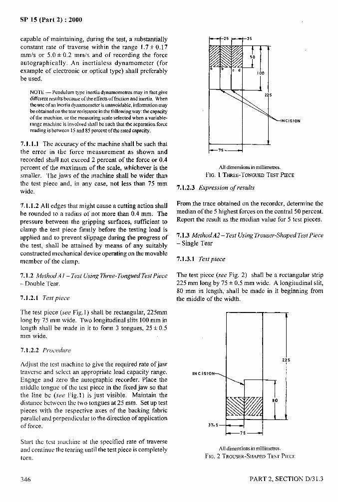
.
.—
SP 15 (Part 2) :2000
capable of maintaining, during the test, a substantiallyconstant rate of traverse within the range 1.7 + 0.17mm/s or 5.0 + 0.2 mm/s and of recording the forceautograph ically. An inertialess dynamometer (forexample of electronic or optical type) shall preferably a
100
be used.
NOTE— Pendulum type inertia dynamometres may in fact give I
different results becauseof the effectsoftilction and inertia. When225
the use of an inertiadynamometerisunavoidable, informationmaybe obtainedon the tear resistancein the followingway: the capacityof the machine, or the measuring scale selected when a variable-range machine is involved shall be such that the separation force
INCISION
reading is between 15and 85 percent of the rated capacity.
7.1.1.1 The accuracy of the machine shall be such that 1
the error in the force measurement as shown and —75 -1
recorded shall not exceed 2 percent of the force or 0.4percent of the maximum of the scale, whichever is the All dimensionsin millimetres.
smaller. The jaws of the machine shall be wider than FIG. 1 THREE-TONGUEDTEST PIECE
the test piece and, in any case, not less than 75 mm7.1.2,3 Expression of results
wide.
7.1.1.2 All edges that might cause a cutting action shall From the trace obtained on the recorder, determine the
be rounded to a radius of not more than 0.4 mm. The median of the 5 highest forces on the central 50 percent.
pressure between the gripping surfaces, sufficient to Report the result as the me~ian value for 5 test pieces.
clamp the test piece firmly before the testing load isapplied and to prevent slippage during the progress of 7.1.3 A4ethodA2 – Test Using Trouser-Shaped Test Piece
the test, shall be attained by means of any suitably – Single Tear
constructed mechanical device operating on the movablemember of the clamp. 7.1.3.1 Test piece
7.1.2 A4ethodA 1 – Test Using Three-Tongued Test Piece The test piece (see Fig. 2) shall be a rectangular strip
– Double Tear. 225 mm long by 75 + 0.5 mm wide. A longitudinal slit,80 mm in length, shall be made in it beginning from
7.1.2.1 Test piece the middle of the width.
The test piece (see Fig. 1) shall be rectangular, 225mmlong by 75 mm wide. Two longitudinal slits 100 mm in
1
length shall be made in it to form 3 tongues, 25+ 0.5mm wide.
7.1.2.2 Procedure
Adjust the test machine to give the required rate of jaw22 5
traverse and select an appropriate load capacity range. INCISIONS
Engage and zero the autographic recorder. Place the tmiddle tongue of the test piece in the fixed jaw so thatthe line bc (see Fig.]) is just visible. Maintain thedistance between the two tongues at 25 mm. Setup test 80
pieces with the respective axes of the backing fabricparallel and perpendicular to the direction of application
1t t
of force. 37.5 4
~75—
Start the test machine at the specified rate of traverseand continue the tearing until the test piece is completely AHdimensionsin millimetres.
torn. FIG. 2 TROUSER-SHAPEDTEST PIECE
I
I ‘
I
346 PART 2, SECTION D/3 1.3
/
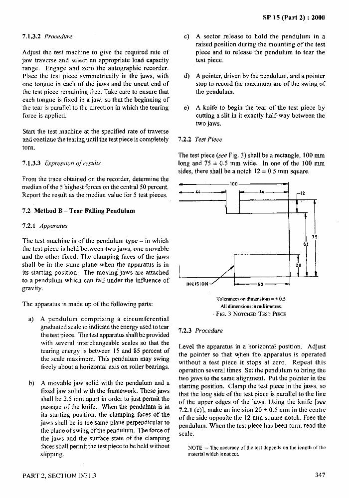
,4,..—
7.1.3.2 Procedure
Adjust the test machine to give the required rate ofjaw traverse and select an appropriate load capacityrange. Engage and zero the autographic recorder.Place the test piece symmetrically in the jaws, withone tongue in each of the jaws and the uncut end ofthe test piece remaining free. Take care to ensure thateach tongue is fixed in a jaw, so that the beginning ofthe tear is parallel to the direction in which the tearingforce is applied.
Start the test machine at the specified rate of traverseand continue the tearing until the test piece is completelytorn.
7.1.3.3 Expression of results
From the trace obtained on the recorder, determine themedian of the 5 highest forces on the central 50 percent.Report the result as the median value for 5 test pieces.
7.2 Method B – Tear Falling Pendulum
7.2.1 Apparatus
The test machine is of the pendulum type – in whichthe test piece is held between two jaws, one movableand the other fixed. The clamping faces of the jawsshall be in the same plane when the apparatus is inits starting position. The moving jaws are attachedto a pendulum which can fall under the influence ofgravity.
The apparatus is made up of the following parts:
a) A pendulum comprising a circumferentialgraduated scale to indicate the energy used to tear
the test piece. The test apparatus shall be providedwith several interchangeable scales so that the
tearing energy is between 15 and 85 percent ofthe scale maximum. This pendulum may swingfreely about a horizontal axis on roller bearings.
b) A movable jaw solid with the pendulum and afixed jaw solid with the framework. These jawsshall be 2.5 mm apart in order to just permit thepassage of the knife. When the pendulum is inits starting position, the clamping faces of thejaws shall be in the same plane perpendicular tothe plane of swing of the pendulum. The force ofthe jaws and the surface state of the clampingfaces shall permit the test piece to be held withouts[ipping.
PART 2, SECTION D/3 1.3
c)
d)
e)
7.2.2
SP 15 (Part 2) :2000
A sector release to hold the pendulum in araised position during the mounting of the testpiece and to release the pendulum to tear thetest piece.
A pointer, driven by the pendulum, and a pointerstop to record the maximum arc of the swing ofthe pendulum.
A knife to begin the tear of the test piece bycutting a slit in it exactly half-way between thetwo jaws.
Test Piece
The test piece (see Fig. 3) shall be a rectangle, 100 mmlong and 75 + 0.5 mm wide. In one of the 100 mmsides, there shall be a notch 12 + 0.5 mm square.
“’__l ‘“= r“
e
t
1(-
$
7 5
63
1
20
11
lNCISION~
Toleranceson dimensions=* 0.5
Alldimensionsin millimetres,
. FIG. 3 NO’PXEDTESTPIECE
7.2.3 Procedure
Level the apparatus in a horizontal position. Adjustthe pointer so that when, the apparatus is operatedwithout a test piece it stops at zero. Repeat thisoperation several times. Set the pendulum to bring thetwo jaws to the same alignment. Put the pointer in thestarting position. Clamp the test piece in the jaws, sothat the long side of the test piece is parallel to the lineof the upper edges of the jaws. Using the knife [see7.2.1 (e)], make an incision 20 + 0.5 mm in the centreof the side opposite the 12 mm square notch. Free thependulum. When the test piece has been torn, read thescale.
NOTE — The accuracy of the test depends on the length of thematerialwhich isnot cut.
347

SP 15 (Part 2) :2000
7.2.4 Expression qf Results a) The test method used (that is, A 1, A2 or B )
For each series of test pieces, determine the median ofand the rate of traverse (method A 1 or A2);
the 5 energy values obtained in the longitudinal direction b) The individual results obtained on each of theand in the transverse direction respectively. 10 test pieces; and
8 TEST REPORTc) The median values in the longitudinal and
The test report shall include the following particulars: transverse directions.
348 PART 2. SECTION D/3 1.3
.
A—-_
SP 15 (Part 2) :2000-..
METHODS OF TEST FORCOATED AND TREATED FABRICS
PART 4 DETERMINATION OF RESISTANCE TO DAMAGE BY FLEXING
[Source : IS 7016 (Part 4) : 1987]
Flex testing provides usefhl information about the @rability of treated fabrics. It is important in accelerated flexingtests to ensure that the specified air temperature is maintained during the test. This may be achieved either bymaintaining adequate ventilation around the test pieces or by controlling the air temperature within any closedcontainer in which the test apparatus maybe mounted.
Two methods are described here. In the De-Mattia test, a test specimen is folded in three and subjected to repeatedbending through an angle of approximately 180°. In the Schildknecht test, the specimens are mounted in the form ofa cylinder and, when flexed, assume a concertina shape; a larger area is, therefore, subjected to flexing than in theDe-Mattia test and the creases are random as in clothing applications.
Flex testing provides useful information for the ability of coated fabrics to resist the development of cracks or thegeneral mechanical deterioration of the material as a result of a relatively large number of flexes. There is no sharpend-point in a flexing test for a coated fabric and it has not been found possible to define any arbitrary stage in thebreak down of the coating which will ensure agreement between laboratories using similar machines.
1 SCOPE
Itprescribes two methods for determination of resistanceto damage by flexing of fabrics coated with rubber orplastics.
2 DE-MATTIA METHOD
2.1 Apparatus
A flex testing machine consisting of pairs of flat gripsof each pair being positioned vertically abovethe other. One of the grips of each pair shall becapable of a reciprocating motion in a vertical plane;the rate of movement of the reciprocating grip being5.0 + 0.2 Hz.
Each pair of grips shall be so positioned that they are70 + 1 mm apart when in the open position and12.5 + 0.5 mm apart when in the closed position.
2.1.1 Suitable machine for this test is the De-Mattia flex
tester or equivalent.
2.2 Sampling
The sample shall be cut so that it is as representative aspossible of the whole consignment. The test piece shallbe taken at least 0.05 m from the selvedge and at least1 m from the beginning or end of the piece.
PART 2, SECTION D/3 1.4
2.3 Test Pieces
2.3.1 Dimensions
The standard test piece shall consist of a rectangularstrip about 125 mm long and 37.5 + 1 mm wide.
NOTE— Bysuitableincreasesin the width of grips, the test piecessize may be increased so as to permit subsequent hydrostatic headtests to be conducted.
2.3.2 Number
For each series of test, cut six test pieces, three parallelto the longitudinal direction and three parallel to thetransverse direction. No two test pieces shall containthe sample threads of the fabric in the direction to betested.
2.3.3 Conditioning
Condition the test pieces at 27 + 2°C and 65 + 2 percentrelative humidity for 48 hours prior to testing. Subjectto agreement between the purchaser and the supplier,the conditioning time may be curtailed to 24 hours. Forall test purposes, the minimum time between
vulcanization or curing and testing shall be 16 hours.Whenever possible, the time between vulcanization orcuring and testing should not exceed three months. Inother cases, tests shall be made within two months ofthe date of receipt of the product by the customer.
349
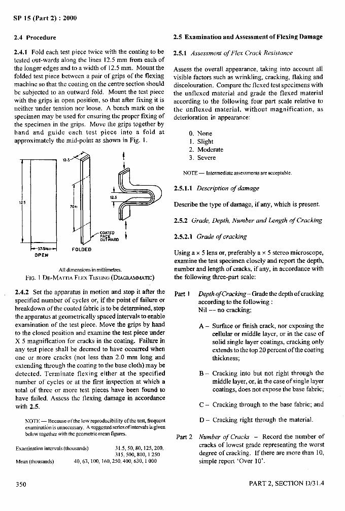
4-
SP 15 (Part 2) :2000
2.4 Procedure
2.4.1 Fold each test piecetested out-wards along the
twice with the coating to belines 12.5 mm from each of
the longer edges and to a width of 12.5 mm. Mount thefolded test piece between a pair of grips of the flexingmachine so that the coating on the centre section shouldbe subjected to an outward fold. Mount the test piecewith the grips in open position, so that after fixing it isneither under tension nor loose. A bench mark on thespecimen may be used for ensuring the proper fixing ofthe specimen in the grips. Move the grips together byhand and guide each test piece into a fold atapproximately the mid-point as shown in Fig. 1.
&37.s?O.14
OPENFOLDED
t
+
4!+12.5
t
All dimensionsin millimetres.
FIG. 1 DE-MATI’IAFLEXTESTING(DIAGRAMMATIc)
2.4.2 Set the apparatus in motion and stop it after the
specified number of cycles or, if the point of failure orbreakdown of the coated fabric is to be determined, stopthe apparatus at geometrically spaced intervals to enable
examination of the test piece. Move the grips by handto the closed position and examine the test piece underX 5 magnification for cracks in the coating. Failure in
any test piece shall be deemed to have occurred when
one or more cracks (not less than 2.0 mm long andextending through the coating to the base cloth) maybedetected. Terminate flexing either at the specified
number of cycles or at the first inspection at which atotal of three or more test pieces have been found to
have failed. Assess the flexing damage in accordancewith 2.5.
NOTE— Because of the low reproducibility of the test, frequentexamination isunnecesswy. A suggestedseriesof intervalsisgivenbelow together with the geometric mean figures.
Examination intervals (thousands) 31.5,50,80, 125,200,315,500,800, 1250
Mean (thousands) 40,63, 100, 160,250,400,630, 1000
350
2.5 Examination and Assessment of Flexing Damage
2.5.1 Assessment of Flex Crack Resistance
Assess the overall appearance, taking into account allvisible factors such as wrinkling, cracking, flaking anddiscoloration. Compare the flexed test specimens withthe unflexed material and grade the flexed materialaccording to the following four part scale relative tothe unflexed material, without magnification, asdeterioration in appearance:
O. None1. Slight2. Moderate
3. Severe
NOTE — Intermediateassessmentsare acceptable.
2.5.1.1 Description of damage
Describe the type of damage, if any, which is present.
2.5.2 Grade, Depth, Number and Length of Cracking
2.5.2.1 Grade of cracking
Using a x 5 lens or, preferably a x 5 stereo microscope,examine the test specimen closely and report the depth,number and length of cracks, if any, in accordance withthe following three-part scale:
Part 1 Depth ofCracking– Grade the depth of crackingaccording to the following :Nil — no cracking;
A–
B–
c–
D-
Surface or finish crack, nor exposing thecellular or middle layer, or in the case ofsolid single layer coatings, cracking onlyextends to the top 20 percent of the coatingthickness;
Cracking into but not right through themiddle layer, or, in the case of single layercoatings, does not expose the base fabric;
Cracking through to the base fabric; and
Cracking right through the material.
Part 2 Number of Cracks – Record the number ofcracks of lowest grade representing the worstdegree of cracking. If there are more than 10,simple report ‘Over 10’.
PART 2, SECTION D/3 1.4
.—...
‘7*.-,.-.‘.a>.
,,,
-.
k.,..
I
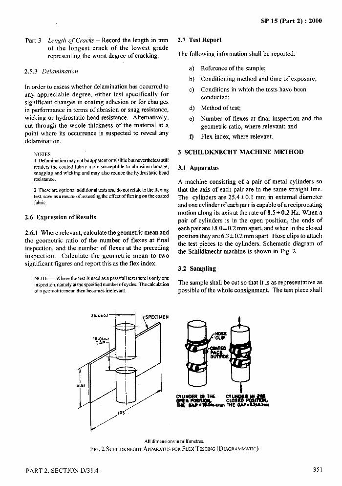
- .-
SP 15 (Part 2) :2000
Part 3 Length Of Cracks – Record the length in mmof the longest crack of the lowest graderepresenting the worst degree of cracking.
2.5.3 Delamination
In order to assess whether delamination has occurred toany appreciable degree, either test specifically forsignificant changes in coating adhesion or for changesin performance in terms of abrasion or snag resistance,wicking or hydrostatic head resistance. Alternatively,
cut through the whole thickness of the material at apoint where its occurrence is suspected to reveal anydelamination.
NOTES1Delaminationmay not be apparentor visible but neverthelessstillrenders the coated fabric more susceptible to abrasion damage,snagging and wicking and may also reduce the hydrostatic headresistance.
2 These are optional additional tests and do not relateto the flexingtest, save as a means of assessingthe effect of flexing on the coatedfabric.
2.6 Expression of Results
2.6.1 Where relevant, calculate the geometric mean andthe geometric ratio of the number of flexes at finalinspection, and the number of flexes at the precedinginspection. Calculate the geometric mean to twosignificant figures and report this as the flex index.
NOTE— Where the testis used as a pass/fail test there is only oneinspection,namelyatthe specifiednumberof cycles. The calculationof a geometric mean then becomes irrelevant.
1’SO*1
L
2.7 Test Report ->
The following information shall be reported:f
a)
b)
c)
d)
e)
o
‘~,~+,---.’
Reference of the sample;
Conditioning method and time of exposure;
Conditions in which the tests have beenconducted;
Method of test;
Number of flexes at final inspection andgeometric ratio, where relevant; and
Flex index, where relevant.
the
3 SCHILDKNECHT MACHINE METHOD
3.1 Apparatus
A machine consisting of a pair of metal cylinders sothat the axis of each pair are in the same straight line.The cylinders are 25.4 + 0.1 mm in external diameterand one cylinder of each pair is capable of a reciprocatingmotion along its axis at the rate of 8.5+ 0.2 Hz. When apair of cylinders is in the open position, the ends ofeach pair are 18.0 +0.2 mm apart, and when in the closedposition they are 6.3 +0.2 mm apart. Hose clips to attachthe test pieces to the cylinders. Schematic diagram ofthe Schildknecht machine is shown in Fig. 2.
3.2 Sampling . .
The sample shall be cut so that it is as representative aspossible of the whole consignment. The test piece shall &,,
— b
l“105’
All dimensionsin millimetres,
FM, 2 SCHILDKNEGHTAPPARATUSFORFLEXTESTING(DIAGRAMMATIC)
PART 2, SECTION D/3 1.4 351
SP 15 (Part 2) :2000
be taken at least 0.05 mm from the selvedge and at least1 m from the beginning or end of the piece.
3.3 Test Piece
3.3.1 Dimensions
The standard test piece shall consist of a rectangularstrip 105 mm long and 50 + 1 mm wide.
NOTE — When hydrostatic head tests are to be subsequentlyconducted, the size of the test piece used for flexing shall be105mm x 65mm and mountedon the metal cylinderinaccordancewith the figure.
3.3.2 Number
For each series of tests cut six test pieces, three parallelto the longitudinal direction, and three parallel to thetransverse direction. No two test pieces shall containthe same threads of the fabric in the direction to be tested.
3.3.3 Conditioning
Condition the test pieces at 27 + 2°C and 65 + 2 percent
relative humidity for 48 hours prior to testing. Subject
to agreement between the purchaser and the supplier,
the conditioning time may be curtailed to 24 hours. For
all test purpose, the minimum time between
vulcanization or curing and testing shall be 16 hours.
Whenever possible, the time between vulcanization or
curing and testing should not exceed three months. In
other cases, tests shall be made within two months of
the date of receipt of the products by the customer.
3.4 Procedure
Mount each test piece with coating to be tested out-wards
around two opposing cylinders that are in the fully open
position with the length of the test piece around the
circumference of the cylinders. Secure the test pieces
into position on each cylinder by means of a hose clip
in such a manner that the edge cylinder and hose clip
are coincident. Set the apparatus in motion and stop it
after the specified number of cycles or, if the point of
failure or breakdown of the coated fabric is to be
determined, stop the apparatus at geometrically spaced
intervals to enable examination of the test piece. Move
the grips by hand to the closed position and examine
the test pieces under x 5 magnification for cracks in the
coating. Failure in any test piece shall be deemed to
have occurred when one or more cracks (not less than
2.0 mm long and extending through the coating to the
base cloth) can be detected. Terminate flexing either at
the specified number of cycles or at the first inspection
at which a total of three or more test pieces have been
found to have failed. Assess the flexing damage in
accordance with 3.5.
NOTE— Because of the low reproducibility of the test, frequentexaminationis unnecessary.Asuggestedseries of intervats is givenbelow,togetherwiththe geometricmean figures..
Examine intervals(thousands) 31.5,50,80, 125,200,315,500,800, 1250
Mean (thousands) 40,63, 100, 160, 250; 400,630, 1000
3.5 Expression of Results
Where relevant, calculate the geometric mean and thegeometric ratio of the number of flexes at finalinspection, and the number of flexes at the precedinginspection. Calculate the geometric mean to twosignificant figures and report this as the flex index.
NOTE — Where the testis used as a pass/fail test there is only oneinspection,namelyatthe specifiednumberof cycles. The calculationof a geometricmean then becomes irrelevant.
3.6 Test Report
The following information shall be reported:
a)
b)
c)
d)
e)
o
Reference of the sample;
Conditioning method and time of exposure;
Conditions in which the tests have beenconducted;
Method of test;
Number of flexes at final inspection and thegeometric ratio, where relevant; and
Flex index, where relevant.
i
I
352
I
PART 2, SECTION D/3 1.4
i,
I
SP 15 (Part 2) :2000
METHODS OF TEST FOR COATED AND TREATED FABRICS
PART 5 DETERMINATION OF COATING ADHESION STRENGTH
[Source: IS 7016 (Part 5) : 1987]
1 SCOPE
R describes method of test for determination of coatingadhesion strength of coated and treated fabrics in whichthere is a distinct coating either on one side or both sides.
2 APPARATUS
2.1 Tensile Testing Machine
The tensile testing machine shall be provided with meansfor indicating or preferably for recording the maximumload applied to the specimen in stretching. Under theconditions of use, the error of the indicated or recordedmaximum load at any point in the range in which themachine is used shall not exceed* 1 percent of the load,and the error of the indicated or recorded maximumjaw separation shall not exceed 1 mm. The central pointsof the two jaws of the machine shall be in the line ofpull, the front edges shall be perpendicular to the lineof pull, and their clamping faces shall be in the sameplane. The jaws shall be capable of holding the specimenwithout allowing it to slip shall be so designed that theydo not cut or otherwise weaken the specimen and shallbe wider than the test specimen. The faces of the jawsshould preferably be smooth and flat, but when thespecimens cannot be held with flat-faced jawssatisfactorily even with packing, engraved or corrugated
jaws may be used.
The machine shall be fitted with a suitable means ofmeasuring increase in length of the central 100 mmsection of the test specimen during the course of and atthe completion of each test cycle.
NOTE— Piecesof felt approximately3 mm t.lickhavebeenfoundto be suitable for packing but the choiceoftype ofjaws and packingshould be that combination which gives the highest bretilng loadand does not cause an undue numberof breaks in closeproximitytothe edgesof thejaws. Suitablepackingmaterialsforuse with eithersmooth or corrugated jaws include paper, felt, leather, plastics orrobbersheets. ●
2.1.1 Constant-Rate-of-Traverse Machines
After first 5 seconds of the test, average rate-of-traverseof pulling jaws in any 2 seconds interval shall not differ
by more than 5 percent from average rate-of-traverseover the whole period of the test.
2.1.1.1 The rate of travel of the power-driven grip shallbe 100+ 10 mm/min. Alternative permitted rates oftravel are 50 mm/min and 300 mm/min, when agreedbetween the manufacturer and the user.
3 TEST PIECE
3.1 Dimensions
The test piece shall be 50 + 0.5 mm wide and of such alength as to permit separation of coating from the fabricover a length of at least 100 mm.
NOTE — Test piece shall be taken avoiding uncoated surface andselvedge and shall be taken from a d&mwe of not less than100 mm from the end of the roll.
3.2 Preparation
3.2.1 Standard Method
Where the strength of the coating film on the fabricexceeds the adhesive bond, as with thick films, preparethe test piece by carefilly cutting the coating through tothe fabric along two parallel cuts, A and B 25.0 k 0.5mm apart as shown in Fig. 1. Cut A extends from one
end of the test piece to within 25 mm of the other end.Cut B extends to within 50 mm of that end. Join theends of cuts A and B with a diagonal cut C, through thecoating to the fabric. Work the edge of a knife underthe point formed by cuts A and Canal separate the peelingstrip so formed from the fabric for a distance of 50 mmfrom that point.
3.2.2 Alternative Methoa!r
3.2.2.1 Using two pieces of the test material
Take two pieces of the test material about 75 mm wideand about 200 mm long. Prepare the faces of the materialby light buffig and cement the two pieces together usinga suitable adhesive and applying it strictly in accordancewith the recommendations of the adhesive suppliers.
.. ...3...
PART 2, SECTION D/3 1.5 353
I\ \
I I
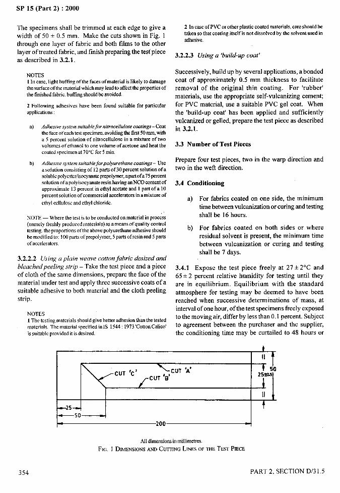
SP 15 (Part 2) :2000..—
The specimens shall be trimmed at each edge to give awidth of 50 + 0.5 mm. Make the cuts shown in Fig. 1through one layer of fabric and both films to the otherlayer of treated fabric, and finish preparing the test pieceas described in 3.2.1.
NOTES1In case, light buft%rgof the faces of material is likely to damagethe surfaceof the materialwhich may lead to aftkctthe propertiesofthe finished fabric, butl%rgshould be avoided.
2 Following adhesives have been found suitable for particularapplications:
@ Adhesive system suitable~or nitrocelhdose coatings – Coatthe face of eachtest specimen,avoidingthe first50MM,witha S percent solution of nitrocelhdose in a mixture of twovolumes of ethanol to one volume of acetone and heat thecoated specimen at 70”Cfor 5 min.
b) Adhesive system suitobleforpolyurethane coatings – Usea solution consistingof12 parts of 30 percent solution of asolublepolyestdisocyanate prepolymer,apart of a 75percentsolution of a polyisocyanateresinhaving anNCO contentofapproximate 13 percent in ethyl acetate and 1 part of a 10percent solution of commercial accelerators in a mixture of
ethyl cellulose and ethyl chloride.
NOTE— Where the testis to be conducted on material in process(namely freshly produced materials) as a means of quality controltesting. the proportions of the above polyurethaneadhesiveshouldbe modified to: 100parts ofprepolymer, 5 parts ofresin and 5 partsof accelerators.
3.2.2.2 Using a plain weave cotton fabric desized and
bleachedpeeling strip – Take the test piece and a pieceof cloth of the same dimensions, prepare the face of thematerial under test and apply three successive coats of a
suitable adhesive to both material and the cloth peelingstrip.
NOTES1The testing materials should give better adhesion than the testedmaterials, Thematerial specified in IS 1544:1973 ‘CottonCalico’is suitable provided it isdesized.
2 In case of PVCor other plastic coated materials, care should betaken so that coating itself is not dissolved by the solvent used inadhesive.
3.2.2.3 Using a ‘build-up coat’
Successively, build up by several applications, a bondedcoat of approximately 0.5 mm thickness to facilitate
removal of the original thin coating. For ‘rubber’
materials, use the appropriate self-vulcanizing cement;for PVC material, use a suitable PVC gel coat. When
the ‘build-up coat’ has been applied and sufficiently
vulcanized or gelled, prepare the test piece as described -in 3.2.1.
3.3 Number of Test Pieces
Prepare four test pieces, two in the warp direction andtwo in the weft direction.
3.4 Conditioning
a)
b)
For fabrics coated on one side, the minimumtime between vulcanization or curing and testing
shall be 16 hours.
For fabrics coated on both sides or where
residual solvent is present, the minimum time
between vulcanization or curing and testingshall be 7 days.
3.4.1 Expose the test piece freely at 27+ 2°C and65 =t2 percent relative humidity for testing until they
are in equilibrium. Equilibrium with the standard
atmosphere for testing may be deemed to have beenreached when successive determinations of mass, atinterval of one hour, of the test specimens freely exposedto the moving air, differ by less than 0.1 percent. Subjectto agreement between the purchaser and the supplier,
the conditioning time may be curtailed to 48 hours or
t
I II f!
IcUT ‘C’ x CUT ‘A’
CUT ‘B’259J0
II f
+25- t
—50 4. 200 t
Alldimensionsin millimetres.
FIG. 1 DIMENSIONSANIICUITINGLINESOFTHETESTPIECE
354 PART 2, SECTION D/3 1.5
i:
,
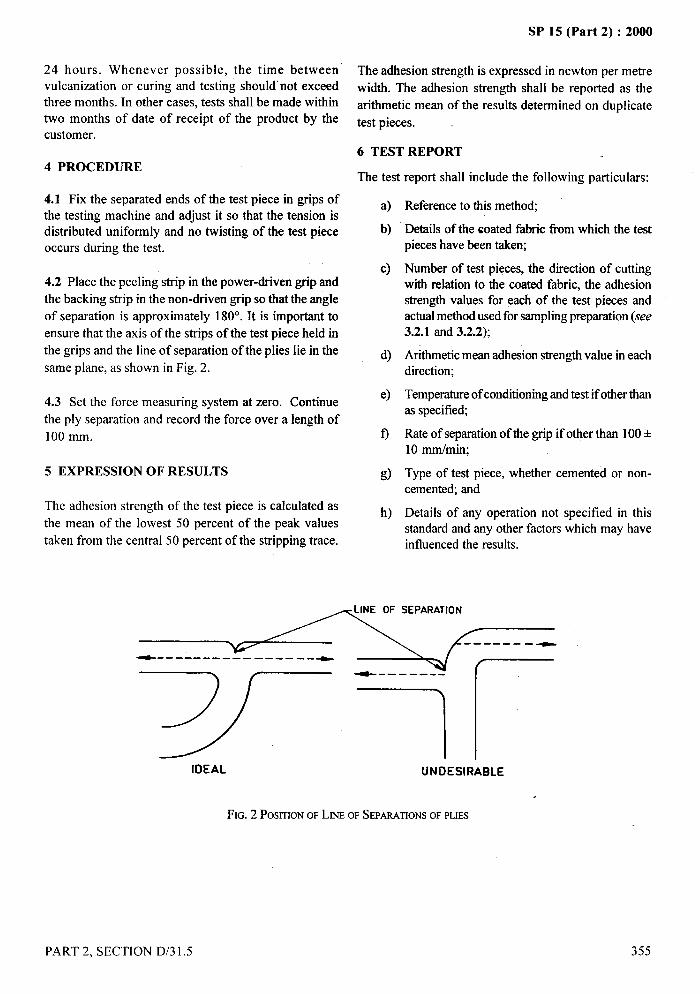
-—. - .— - .--.-
24 hours. Whenever possible, the time between
vulcanization or curing and testing should’ not exceed
three months. In other cases, tests shall be made within
two months of date of receipt of the product by the
customer.
4 PROCEDURE
4.1 Fix the separated ends of the test piece in grips of
the testing machine and adjust it so that the tension isdistributed uniformly and no twisting of the test piece
occurs during the test.
4.2 Place the peeling strip in the power-driven grip and
the backing strip in the non-driven grip so that the angle
of separation is approximately 180°. It is important to
ensure that the axis of the strips of the test piece held in
the grips and the line of separation of the plies lie in the
same plane, as shown in Fig. 2.
4.3 Set the force measuring system at zero. Continue
the ply separation and record the force over a length of
100 mm.
5 EXPRESSION OF RESULTS
The adhesion strength of the test piece is calculated as
the mean of the lowest 50 percent of the peak values
taken from the central 50 percent of the stripping trace.
SP 15 (Fart 2) : ZU(NI
The adhesion strength is expressed in newton per metre
width. The adhesion strength shall be reported as the
arithmetic mean of the results determined on duplicate
test pieces. .
6 TEST REPORT
The test report shall include the following particulars:
a)
b)
c)
Reference to this method;
Details of the coated fabric horn which the testpieces have been taken;
Number of test pieces, the direction of cuttingwith Aation to the coated fabric, the adhesionstrength values for each of the test pieces andactual method used for sampling preparation (see3.2.1 and 3.2.2);
Arithmetic mean adhesion strength value in eachdirection;
Temperature of conditioning and test if other thanas specified;
Rate of separation of the grip if other than 100+10 mm/min;
Type of test piece, whether cemented or non-cemented; and
Details of any operation not specified in thisstandard and any other factors which may haveinfluenced the results.
SEPARATION
-------- ____ ._
“7)-+_=----m/------
7 rIDEAL UNDESIRABLE
.
FIG.2 POSITIONOFLm OFSEPARATIONSOFPLIES
PART 2, SECTION D/3 1.5 355
I
1?

SP 15 (Part 2) :2000.-
METHODS OF TEST FOR
COATED AND TREATED FABRICS
PART 6 DETERMINATION OF BURSTING STRENGTH
[Source : IS 7016 (Part 6) : 1984]
Two methods of test (A and B) have been included in this standard. Values obtained using Method A are not
necessarily comparable with those obtained when using Method B. Therefore, when speci~ing a coated fabric forwhich a bursting strength requirement applies, the purchaser and the supplier should agree mutually the method oftest to be employed.
Method A is recommended for use with those types of coated fabrics for which hydraulic bursting methods are notconsidered appropriate owing to the excessive pressures involved or where the risk of mechanical damage to thematerial in use is more relevant (for example, heavy weight double texture natural rubber coated fabrics).
This standard contains clauses 5.1 and 5.2 which call for an agreement between the purchaser and the supplier.
1 SCOPE
1.1 It prescribes two methods (A and B) for thedetermination of the bursting strength of coated andtreated fabrics.
1.1.1 Method A uses tensile testing machine with aring clamp and steel ball whilst Method B uses adiaphragm bursting tester operated by hydraulicpressure.
2 APPARATUS
2.1 Method A (see Fig. 1).
2.1.1 Principle
A coated fabric is securely clamped between rigid coaxialapertures. A polished steel ball traversing at a fixedspeed, is pressed against the coated fabric specimen untilrupture occurs. The force required to cause the ruptureis recorded.
2.1.2 Tensile Testing Machine
It shall be power driven and equipped with a suitabledynamometer. It shall be capable of maintaining asubstantially constant rate of traverse of the moving headduring the test and be fitted with an autographic recorder.An inertialess dynamometer (of electrical or optical type,for example) may be used. The accuracy of the machine
shall be such that the error in the force measurement asshown and recorded does not exceed 2 percent of the
356
force of 0.5 percent of the maximum of the scale,whichever is the greater.
NOTE — Apendulum-type inertia dynamometer may in fwt givedifferentresultsbecauseof the effectsoftilction and inertia. Whentheuse of an inertiadynamometeris unavoidable, informationmaybe obtained in the following way. The capacity of the machine orthe measuring scale selected, when a variable-range machine isinvolved,shall be such that the burstingforce is between 15percentand 85 percentof the rated capacity.
2.1.2.1 The tensile testing machine shall be providedwith a bursting attachment, such that the test piece isheld securely by a ring mechanism of internal diameter45 + 0.50 mm, with the centre of the test piece pressed
against a polished steel ball of diameter 25.2 + 0.02mm until the test piece ruptures. The direction of motionof the ring-clamp or steel ball shall be at right angles tothe plane of the fabric.
2.1.2.2 The central points of the two jaws of the machineshall be concentric and shall be in the line of pull, thefront edges being perpendicular to the line of pull, andtheir clamping faces in the same plane. The jaws shallbe capable of holding the specimen without allowing itto slip, shall be so designed that they do not cut orotherwise weaken the specimen, and shall be wider thanthe test specimen. The faces of the jaws should preferably
be smooth and flat but when the specimens cannot besatisfactorily held with flat-faced jaws even with packing,
engraved or corrugated jaws maybe used.
In case of engraved jaws, the clamping surfaces of theupper and lower clamps shall be grooved concentricallysuch that the crowns of the grooves of one plate fit the
PART 2, SECTION D/3 1.6
/
I I
!,!
I
I

.4— . ..-
SP 15 (Part 2) :2000
~,ato.so-l-TE51
Qz LOWER CLAMP
2s.2:0.02
i POLISHEO.— —. STEEL BALL
I
i
All dimensionsin millimetres.
FIG. lAPPARATUSFORMETHODA
grooves of theother. Thegrooves shall benot lessthan0.8 mmapart and not less than 0.15 mm deep. Thegrooves shall start no further than 3 mm from the edgeof the aperture and shall be rounded to a radius of notgreater than 0.4 mm. The lower inner edge of the upperclamp and the upper inner edge of the lower clamp shallbe rounded off to a radius of 0.5 mm.
NOTE— Pieces of felt approximately3 mm tldckhave beenfoundto be suitablefor packing,but the choiceoftype ofjaws andpackingshould be that combination which gives the highest bretilng loadand doesnot cause an unduenumberof breaks in closeproximitytothe edges of thejaws. Suitablepacking’materialsforuse with eithersmooth or corrugated jaws include paper, felt, leather, plastics orrubber sheet.
2.2 Method B (see Fig. 2)
2.2.1 Principle
A coated fabric specimen is clamped between coaxialapertures. An elastic diaphragm is caused to exertpressure on the coated fabric specimen by theintroduction of liquid below the diaphragm at a constantrate. The pressure required to cause the coated fabricspecimen to burst is recorded.
2.2.2 Testing Machine
It shall be either mechanically or manually operated. It
shall permit the clamping of the test piece between twocircular clamps of diameter not less than 55 mm andhaving coaxial apertures of 30 + 0.5 mm diameter.
2.2.2.1 The clamping surfaces of the upper and lowerclamps shall be grooved concentrically such that the
crowns of the grooves of one plate fit the grooves of theother. The grooves shall be not less than 0.8 mm apartand not less than 0.15 mm deep. The grooves shall startno timther than 3 mm from the edge of the aperatureand shall be rounded to a radius of not greater than0.4 mm. The bottom inner edge of the upper clamp shallbe rounded to a radius of 0.5 mm. The lower clampshall be integral with the chamber in which liquid isintroduced. The chamber shall be covered with a rubber
diaphragm fitted to expand through the aperture andexerting pressure on the coated fabric between clamps.
2.2.3 Pressure Gauge
The apparatus shall be provided with a means for
transmitting hydraulic pressure to the rubber diaphragm.A pressure gauge of the maximum reading type, ofappropriate capacity and graduated in kgf/cm2 or kilo-
pascals shall be provided for registering the burstingpressure. It shall preferably be gsed within the rangefrom 25 percent to 75 percent and’ in no c~e outside therange from 15 percent to 85 percent of the maximumcapacity of the scale. It shall at any point within theworking range be accurate to within 1 percent of the
maximum capacity of the scale. The pressure gaugeshall be calibrated at least once in a year to maintainthe specified accuracy.
3 SAMPLING
The sample shall be so cut that it is as representative aspossible of the whole consignment. The test pieces shallbe cut at least 100 mm from the selvedge and at least1 m from the extremity of the piece.
t
PART 2, SECTION D/3 1.6 357
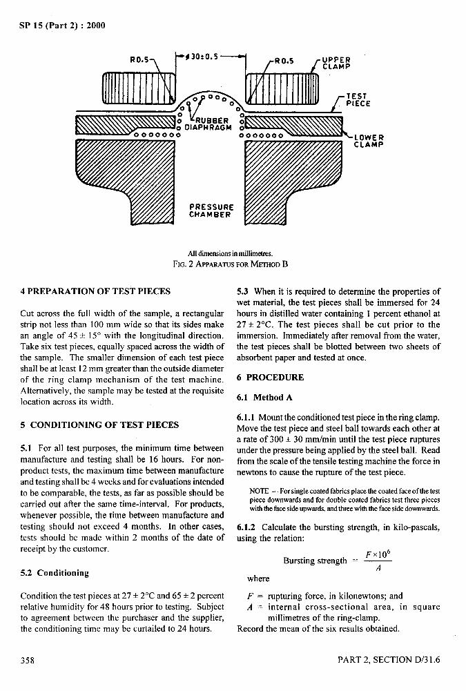
SP 15 (Part 2) :2000
.—. --;
‘!
Alldimensionsin millimetres.
FIG.2 APPARATUSFORMETHODB
4 PREPARATION OF TEST PIECES
Cut across the full width of the sample, a rectangularstrip not less than 100 mm wide so that its sides makean angle of 45 + 15° with the longitudinal direction.Take six test pieces, equally spaced across the width ofthe sample. The smaller dimension of each test piece
shall beat least 12 mm greater than the outside diameterof the ring clamp mechanism of the test machine.Alternatively, the sample may be tested at the requisitelocation across its width.
5 CONDITIONING OF TEST PIECES
5.1 For all test purposes, the minimum time between
manufacture and testing shall be 16 hours. For non-
product tests, the maximum time between manufactureand testing shall be 4 weeks and for evaluations intended
to be comparable, the tests, as far as possible should be
carried out after the same time-interval. For products,whenever possible, the time between manufacture and
testing should not exceed 4 months. In other cases,
tests should be made within 2 months of the date ofreceipt by the customer.
5.2 Conditioning
Condition the test pieces at 27 + 2°C and 65 + 2 percentrelative humidity for 48 hours prior to testing. Subjectto agreement between thethe conditioning time may
358
purchaser and the supplier,be curtailed to 24 hours.
5.3 When it is required to determine the properties ofwet material, the test pieces shall be immersed for 24hours in distilled water containing 1 percent ethanol at
27+ 2“C. The test pieces shall be cut prior to theimmersion. Immediately after removal from the water,the test pieces shall be blotted between two sheets of
absorbent paper and tested at once.
6 PROCEDURE
6.1 Method A
6.1.1 Mount the conditioned test piece in the ring clamp.Move the test piece and steel ball towards each other ata rate of 300 + 30 mm/min until the test piece rupturesunder the pressure being applied by the steel ball. Readfrom the scale of the tensile testing machine the force innewtons to cause the rupture of the test piece.
NOTE— For single coated fabrics place the coated face of the testpiece downwards and for double coated fabrics test three pieceswith the facesideupwards,andthree with the fam side downwards.
6.1.2 Calculate the bursting strength, in kilo-pascals,using the relation:
Fxl(fBursting strength = —
A
where
F = rupturing force, in kilonewtons; andA = internal cross-sectional area, in square
millimetres of the ring-clamp.Record the mean of the six results obtained.
PART 2, SECTION D/3 1.6
..—SP 15 (Part 2) :2000
6.2 Method B
6.2.1 Place the conditioned test piece over the rubberdiaphragm of the apparatus (see Note under 6.1.1).Secure the clamping ring tightly over the test piecesand increase the pressure on the rubber diaphragm byintroducing liquid into the chamber until the test piecebursts. Allow between 7 and 20 seconds for the pressureto increase from zero to bursting point. Record thepressure required as shown by the maximum indicatingpoint on the gauge and return the pointer to zero. Foreach test piece, record the bursting pressure and notethe form of bursting obtained (namely cross of slit).
NOTE— Ignoreanyburstwhichoccurs at or near the edge of theclamp and repeat the test on another test piece.
6.2.1.1 Calculate the mean of the six results obtainedfor bursting pressure and then apply the diaphragmcorrection factor as given in 6.2.2.
6.2.2 Correction Factor
With the same rate of liquid flow as that employed inP
the test (see 6.2.1), distend the diaphragm, without the
presence of the specimen, but with the clamping ring in -.--
position, and note the pressure required to distend it by .lan amount equal to the average distension of thespecimen at burst. This pressure is the ‘diaphragm
‘~
$,---;correction factor’ and is the value by which the meanbursting pressure should be reduced.
6.2.3 Report the corrected mean bursting pressure asthe bursting strength.
7 TEST REPORT
The test report shall state:
a)
b)
c)
d)
e)
9
Reference of the sample;
Conditioning method and the time of exposure;
Conditions in which the test has been
conducted;
Method of test employed (A and B) and
aperture used;
Bursting strength, expressed in kilo-pascals;
and
For method B, the form of bursting obtained.
. .
PART 2, SECTION D/3 1.6 359
,
I1,
SP 15 (Part 2) :2000
METHODS OF TEST FOR COATED AND TREATED FABRICS
PART 7 DETERMINATION OF RESISTANCE TO PENETRATION BY WATER
[Source: IS 7016 (Part 7) : 1986]
This method is an important performance criteria as it determines the ability of rubber or plastic coated fabric towithstand against water. In order to determine the degree of penetration by water, it is necessary to subject testpieces cut from the coated fabric to known hydrostatic pressure. These tests maybe conducted on coated fabrics asproduced or on test pieces which may have been subjected to ageing or other tests.
This test method is applicable to all types of treated/coated fabrics whether treatecVcoated on one or both sides.
1 SCOPE
1.1 It prescribes methods for determining the resistanceto penetration by water of fabrics coated with rubber orplastics when subjected to a low or high hydrostaticpressure.
1.1.1 Four methods are covered, as follows:
Method Al or A2: Hydrostatic pressure method –
Low rangeMethod B 1 or B2: Hydrostatic pressure method –
High range
1.2 The choice of methods is optional, but considerationshould be given to the nature of service for whichcorrelation test values may be sought.
2 CONDITIONING
Condition the test pieces at 27 + 2°C and 65 =E2 percentrelative humidity for 48 hours prior to testing. Subjectto agreement between the purchaser and the supplier,the conditioning time may be curtailed to 24 hours. Forall test purposes, the minimum time betweenvulcanization or curing and testing shall be 16 hours.Whenever possible the time between vulcanization orcuring and testing should not exceed three months. Inother cases, tests shall be made within two months ofthe date of receipt by the customer of the product.
3 METHOD A – HYDROSTATIC PRESSUREMETHOD – LOW RANGE
3.1 Apparatus
The apparatus shall consist of a central well fitted witha coaxial ring clamp to fasten the test piece over thewell. The apparatus shall introduce water at test-room
temperature from above or below the test piece over a
360
circular area 100 cmz (approximately 113 mm diameter)in diameter at the rate of 10 + 2 mm of hydrostatic head
per second. The rubber tubing connecting the constant-level device and the well shall have an inside diameterof not less than 6 mm.
3.2 Test Piece
3.2.1 The test piece shall be either circular, of diameter130 to 200 mm, or of corresponding square shape. Itshall be taken at least 0.10 m from the selvedge and 1 mfrom the end of the roll.
3.2.2 Unless otherwise specified in the materialspecification, five test pieces shall be tested from eachsample unit.
3.3 Procedure
Conduct the test according to one of the followingmethods.
3.3.1 Method A 1
Wipe all surface water from the clamping surfaces. Laythe test piece smoothly on the face of the lower ring ofthe clamp and fasten the upper plate in place, ensuringthat the coated fabric is in contact with the water andthat no air is trapped between the test piece and thewater. This shall form a watertight compartment. If thetest piece is coated on only one side, place the coated.
side next to the water, unless otherwise specified. In thecase of double coated fabrics, place the more heavily
coated side next to the water, unless otherwise specified.With the Ieveller at the zero position, turn the water onand keep in running at such a rate as to overflowcontinuously. Raise the constant level device at a rate
of 10 mm/s until the first drop of water appears on theunderside of the test piece. No account shall be taken ofvery tine droplets of water which are formed at or near
PART 2, SECTION D/3 1.7
.4—.. _
the clamping edge. Read on the scale the height of thewater above the lever of the test piece.
3.3.2 Method A2
Place the test piece in the clamp, raise the water columnto a predetermined height (1 or 10 m) and record thetime at which the first drop of water appears on theunderside of the test piece.
3.4 Test Report
The test report shall include the following particulars:
a)
b)
c)
d)
e)
f)
g)
The method and procedure used;
The number of test pieces tested;
With method Al, the height of the watercolumn, inmillimetres, atwhich the first drop
of water appeared on the underside of the testpiece, and the average value for all test pieces;
With Method A2, the predetermined height ofthe water column and the elapsed time beforethe first drop of water appeared on theunderside of each test piece, and the averagevalue for all test pieces;
Identification of the material tested;
If applicable, the conditions used for ageingthe test pieces; and
To which side of the coated fabric the waterpressure was applied.
4 METHOD B – HYDROSTATIC PRESSUREMETHOD – HIGH RANGE
4.1 Apparatus
4.1.1 The apparatus shall consist of a hydrostatic testercapable of supplying a minimum pressure of 690 kPa’jwith an accuracy of ~ 7.0 kPa.
4.1.2 The apparatus shall be equipped with two
concentric ring clamps, having an inner diameter of31.5 + 0.5mm, between which the test piece can beclamped. The clamping surfaces shall have concentricgrooves of depth not less than 0.15 mm to prevent the
test piece from slipping during the test. The inside edgesof the ring clamps that come into contact with the test
1)1kPa=O.0102 kgf/cm2.
PART 2, SECTION D/3 1.7
SP 15 (Part 2) :2000
piece shall be rounded to a radius of 0.3 to 0.5 mm toavoid cutting of the test piece.
4.1.3 The lower clamp shall be fitted with a rubberO-ring to avoid leakage when the pressure is applied tothe test piece.
4.1.4 The machine shall have means for applyinghydraulic pressure to the underside of the clamped testpiece until the test piece fails.
4.1.5 The pressure gauge shall be of the Bourdonmaximum-reading type, with graduations which willpermit reading for the entire scale within 1.0 percent ofits maximum capacity. The capacity of the gauge shallbe such that the individual readings will be not less than25 percent and not more than 75 percent of the totalcapacity of the gauge.
4.2 Test Pieces
4.2.1 At least five test pieces shall be cut from samplestaken at random from the roll of coated fabric beingtested. The smallest dimension of the test piece shall beat least 12 mm greater than the outside diameter of thering clamp mechanism of the testing apparatus.
4.2.2 The test pieces shall be taken at least 0.10 m fromthe selvedge and 1 m from the end of the roll.
4.3 Procedure
Conduct the test according to one of the followingmethods.
4.3.1 Method B 1
Before clamping the test piece into the testing machine,bring the water level up flush with the top of the O-ringso that no air pocket exists between the water surfaceand test piece. Unless otherwise specified in the case ofsingle coated fabrics, place the coated side next to thewater. In the case of double-coated fabrics or double-textured fabrics, place the more heavily coated side nextto the water, unless otherwise specified. The temperatureof the water shall be the same as the atmospherictemperature of the testing room, unless otherwisespecified. Increase the pressure at uniform rate ofdisplacement and take a dial reading at the firstappearance of water through the test piece.
4.3.2 Method B2
The specimen should be flexed five times by applyingand releasing the specified pressure. Apply the
361
,,
/
!
I II
..—SP 15 (Ptirt 2) :2000
specified pressure he[cl constant within * 7.0 kPa,
against the test piece for a period of 5 minutes. Anyappearance of”water through the test piece that can bedetected during the specified period will indicate failureto pass the test.
4.4 Test Report
The test report shall include the following particulars:
a) The method and procedure used;
362
b) The number of test pieces tested;
c) With Method B 1, all observed and recordeddate together with the average value ofhydrostatic resistance, in kPa;
d) with Method B2, the specified pressureapplied and the number of test pieces thatwithstood pressure;
e) Identification of the material tested; and
~ If applicable, the specific conditions used forageing or other testing.
PART 2. SECTION D/3 1.7
—.:
I
!,
i
I
‘1
II,
Ii
$..——.—
SP 15 (Part 2) :2000
METHODS OF TEST FORCOATED AND TREATED FABRICS
PART 8 ACCELERATED AGEING
[Source : IS 7016 (Part 8) : 1975]
it is not possible to follow the same procedure for accelerated ageing test for fabrics coated with rubber and plastics
as adopted for other rubber and plastics goods, the main reasons being relatively large area coupled with thincoatings which will not normally provide test pieces suitable for measurement of physical properties.
It is not feasible to establish a fixed and universal relationship between the duration of ageing in the oven and the
useful life of the objects; such relationships can be established only for each individual case.
1 SCOPE
It prescribes the methods of test for accelerated ageing
and simulated service tests of coated and treated fabrics.
2 TEST METHODS
2.1 The following two ageing tests are given:
a) Oven method, and
b) Oxygen pressure method.
2.2 For all test purposes, the minimum time betweenvulcanization or curing and testing shall be 16 hours.
Whenever possible, the time between vulcanization or
curing and testing shall not exceed three months, In
other cases, tests shall be made within two months of
the date of receipt of the product by the customer.
3 TEST PIECES
Test pieces shall be taken at not less than 100 mm fromthe selvedge and not less than 1 m from the end of the
roll or piece. The size of the test piece depends upon
the property to be examined. For examination ofproperties, such as tear, waterproofness, etc, the
dimensions of the test piece shall be those required bythe particular method. For purposes of ascertaining the
degree of stiffness, or decomposition, a test piece notless than 100 mm x 50 mm for the oven method and not
less than 75 mm x 25 mm for the oxygen pressuremethod shall be used.
4 OVEN METHOD
4.1 Apparatus
The air-oven shall be of such a size that the total volumeof the test pieces does not exceed 10 percent of the free
PART 2, SECTION D/3 1.8
air space of the oven. Provision shall be made forsuspending test pieces vertically so that they are notwithin 10 mm of each other or the sides of the oven.Provision shall be made for slow circulation of air inthe oven of not less than three changes and not morethan ten changes per hour. Care shall also be taken thatthe incoming air is heated to the temperature of the ovenbefore coming into contact with the test pieces. Thetemperature of the oven shall be thermostaticallycontrolled so that the test pieces are kept within + 1‘Cof the specified ageing temperature. A thermometershall be placed near the centre of the test pieces beingaged to record the actual ageing temperature.
NOTE— Copper or copper alloys or both together shall not beused for the construction of oven,
4.2 Procedure
Place the test pieces in the oven vertically after theyhave been preheated to the operating temperature. Thetest pieces are to be stationary, free from strain, freelyexposed to air on all sides and not exposed to light.When the ageing period is complete, remove the testpiece from the oven and store and condition at roomtemperature for not less than 16 h or more than 96 h, ina strain-free condition and then condition in accordancewith the details given in the appropriate test method forthe particular physical property being studied.
4.2.1 Where ageing is conducted on the 100 mm x 50mm test pieces, they shall be observed and handled forany signs of softening, stiffening, tackiness, brittleness,discoloration, or other loss of properties, and thepresence or absence of the characteristic odour ofdecomposition shall be noted. This shall be done incomparison with the unaged material.
Where the test pieces are exposed at a temperature of100”C they shall also be examined for additional
363
.-
-“-I,
I
I I
I
4—._
SP 15 (Part 2) :2000
properties, such as tensile strength and tear. Theduration of test shall be 1, 3, 7, 10 or some multiple of7 days and the temperatures of test shall be 70+ 1“C or100 + 1‘C as may be stipulated in the individual materialspecification. The pressure shall be atmospheric.
4.2.2 As far as possible, avoid simultaneous ageing ofdifferent types of compounds in order that migration ofsulphur, anti-oxidants, plasticizers or stabilizers maynot occur. As a guideline, samples maybe aged togetherwhere the following conditions are satisfied :
a) Polymers are of the same general type;b) Vulcanizates having the same sulphur content;c) Vulcanizates having broadly the same type of anti-
oxidant, anti-ozonants and UV absorbers; andd) Vulcanizates having plasticizers of approximately
the same volatility.
5 OXYGEN PRESSURE METHOD
5.1 Apparatus
The oxygen pressure chamber shall consist of a vesselof stainless steel or other suitable material designed toretain an internal atmosphere of oxygen under pressurewith provision for placing test pieces within it andsubjecting them to controlled uniform temperature. Thesize of the vessel is optional but shall be such that thetotal volume of the test pieces does not exceed 10 percentof the free space of the vessel. Copper or brass partsshall be neither within the ageing chamber not used inthe construction of the tubing leading through the oxygenreservoir to the ageing chamber. The heating mediumwhich surrounds the vessel is thermostatically controlledand a thermometer shall be immersed in the heatingmedium. The pressure chamber shall be equipped witha reliable safety valve set at 3 400 kN/mz (approx 34kg f/cm2) and a pressure gauge shall be connected to theapparatus.
NOTE — The beatingmediumisoptional. Water,airorother fluidsknownto be safe inthe presenceof oxygenmay be used. Waterhasan advantagebecauseof its rapid heat transferandnon-combustiblenah]re. If air is nsed, the heatedair shallbe thoroughlycirculatedbymeans of mechanical agitation and baftles shall be used as requiredto preventlocaloverheatinganddeadspots. 011sorothercombustiblefluids are extremelyhazardousinthe presenceofoxygen and shouldnot be used as a heating medium for this test.
5.2 Procedure
Heat the test pieces to the operating temperaturesuspended vertically in the pressure chamber after it hasbeen dried. Before commencing the test, flush out theair inside the chamber by allowing oxygen into it andkeeping the outlet valve open for sufficient time. Thechamber is then filled with oxygen to the requiredpressure.
364
Maintain the test pieces in the vessel stationary, fleefrom strain and freshly exposed to the oxygen on allsides. Pass oxygen into the pressure chamber at apressure of 2050 + 100 kN/m2 (approx 20.5 + 1 kgf/cm2)maintaining the exposure continuous for the specifiedtime, without pressure reduction or opening ofthe chamber. The temperature shall be maintained at70+ 1“C. The duration of the test shall be 24 hours orsome multiple thereof.
5.2.1 When the ageing period is complete, release thepressure in the pressure chamber slowly and uniformly(this requires at least five minutes), taking particularcare to see than all the pressure is released as indicatedby the pressure gauge. Remove the test pieces from thevessel and condition in accordance with the details givenin the appropriate test method for the particular propertybeing studied.
5.2.2 As far as possible, avoid simultaneous ageing ofdifferent types of compounds in order that migration ofsulphur, anti-oxidants, plasticizers of stabilizers may notoccur. As a guideline, samples may be aged togetherwhere the following conditions are satisfied :
a) Polymers are of the same general type;b) Vulcanizates having the same sulphur content;c) Vulcanizates having broadly the same type of
anti-oxidants, anti-ozonants and UV absorbers;and
d) Vulcanizates having plasticizers orapproximately the same volatility.
6 EXPRESSION OF RESULTS
6.1 State the number of test pieces and express the resultsin accordance with the recommendations of theappropriate test method for the particular test beingcarried out.
6.2 Determine the properties of the test pieces aged fordifferent periods as the intervals terminate in the processof ageing.
6.3 Report the test results of both the unaged (0) andthe aged (A) test pieces and record percentage changein ph~sical or mechanical property using the formula :
O- AXIOO
owhere
O = mechanical or physical properties of the testpiece expressed in appropriate units beforeageing, and
A = mechanical or physical properties of the testpiece expressed in the same units after ageing.
6.4 State the physical or mechanical propertiesdetermined and ageing conditions.
PART 2, SECTION D/3 1.9
_. , ,4
SP 15 (Part 2) :2000....
I
METHODS OF TEST FORCOATED AND TREATED FABRICS
PART 9 DETERMINATION OF BLOCKING RESISTANCE
[Source : IS 7016 (Part 9) : 1988]
Blocking tests at elevated temperatures are designed to estimate the relative resistance of fabrics coated withrubber or plastics to blocking. For this purpose, the coated fabric is subjected to a specified load over a defined area
at a specific temperature. The selection of the conditioning time and temperature depends on the type of coating tobe evaluated. This selection determines whether an accelerated temperature or simulated service (heat) testis to beused.
1 SCOPE
It prescribes a method for determining the resistance offabrics coated with rubber or plastics to blocking.
2 TERMINOLOGY
Blocking – Unintentional adhesion between plastic films
or sheetings, or between film or sheeting and anothersurface.
3 APPARATUS
3.1 Glass Plates – approximately 112 mm x 112 mm x3 mm.
3.2 Weight-Pieces – of mass 5.0 kg.
3.3 Oven – Circulating air oven of such a size that thetotal volume of the test assemblies does not exceed 10percent of the free air space of the oven. Provision shallbe made for placing the test assemblies on shelves sothat they are not less than 50 mm from each other orfrom the sides of the oven. The nature of the source ofheat is optional but the source shall be located in the airsupply of the oven. Provision shall be made forcirculation of air through the oven at a rate such as toprovide a minimum of six air changes per hour. Thetemperature of the oven shall be thermostaticallycontrolled to maintain the temperature of the test
assemblies within + 2°C of the specified temperature.Baffles shall be used as required to prevent overheating
and dead-spots.
4 TIME INTERVAL BETWEEN MANUFACTUREAND TESTING
4.1 For all purposes, the minimum time betweenmanufacture and testing shall be 16 h.
4.2 For product tests, whenever possible, the timebetween manufacture and testing should not exceed fourmonths. In other cases, tests should be made withintwo months of the date of receipt by the customer.
5 TEST PIECES
5.1 The test pieces for each sample to be tested shallconsist of six specimens, each 150 mm x 150 mm.
5.2 Test specimens shall be representative of the materialbeing tested. They shall be taken at least 0.10 m fromthe edges of the coated sample and well away from theend. They shall be cut with one edge parallel to thelongitudinal axis of the sample. The longitudinal andlateral axis shall be marked on the test specimens.
6 CONDITIONING OF TEST PIECES
Cut test pieces shall be conditioned, immediately before J,;”
testing, for a minimum or 48 h at 27 + 2°C and 65 + 2.?
percent relative humidity.
7 PROCEDURE
7.1 Arrange the test specimens in pairs, back to back,face to face and back to face, to form a pile 100 mmsquare. Place the test specimens thus arranged betweentwo glass plates (3.1 ). Place the 5.0 kg weight-piece (3.2)
Ion the top plate in the position to ensure an evendistribution of pressure.
7.2 Expose the test assembly for 3 hat a temperature of70+ 2°C in the oven (3.3).
7.3 At the end of the exposure period, remove the testassembly from the oven, immediately take the test piecefrom between the plates and allow it to cool for 3 h.Then carefully separate the test specimens and examinethem for adherence or peeling of the coatings.
PART 2, SECTION D/3 1.9
/
365
SP 15 (Part 2) :2000
7.4 Rate the resistance of the test piece to blocking by 8 TEST REPORT
the scale xiven below :
a)
b)
c)
366
The test report shall include the following particulars:
No blocking--coated surfaces separate withoutany evidence of adhering, a)
Slight blocking – some adherence of coatedb)
surfaces takes place on separation but withoutdetriment to the coating, and
c)
d)Blocking – coated surfaces are difficult toseparate and the coating or a part of the coatingis removed during separation. e)
Reference to this test method;
Identification of the sample;
Total mass on the test piece;
Rating for resistance to blocking, in accordancewith 7.4; and
Any departure from the procedure specified.
PART 2. SECTION D/3 1.9
—.
1-...,--.
METHODS OF TEST FOR
COATED AND TREATED FABRICS
PART 10 LOW - TEMPERATURE BEND TEST
.. .—
SP 15 (Part 2) :2000
.—— -
;
.,,, ,*?=-.,”
,,
[Source : IS 7016 (Part;JO) : 1981]7
Bend test at low temperature is designed for determining the ability to resist cracking or fracturing of coating offabrics coated with rubber or plastics when exposed for definite periods at specified temperature.
1 SCOPE
1.1 It prescribes a method for determining the abilityof fabrics coated with rubber or plastics to resist theeffect of low temperature when subjected to bending atspecified temperatures after definite periods of exposure.lt is applicable to material with a thickness within therange 0.10 to 2.20 mm.
1.1.1 Fabrics coated with rubber or plastics are used inmany applications requiring low temperature flexing.
However, no relation between this test and serviceperformance can be given or implied.
2 APPARATUS
2.1 Cold Chamber
A chamber sufficient in size to contain the bendingfkture used for testing the test pieces and to permit theoperation of the fixture to bend the test piece withoutremoval from the chamber. The cold chiirnber shall alsohave sufficient work space to permit the conditioningof test pieces as outlined in 5. It shall be capable ofmaintaining a uniform atmosphere of cold air or anyother suitable gas at specified temperatures within attolerance of+ 1“C,
2.2 Bending Jig
For bending the test pieces, as shown in Fig. 1 and 2.
2.3 Glass Plates
Sufficient number of glass plates having dimensions ofapproximately 125 mm x 175 mm. The thickness ofthe glass plates shall be such as to permit easy handling.
2.4 Gloves
For handling test pieces within the cabinet and which
PART 2. SECTION D/3 1.10
shall be exposed to the same temperature as the testpieces.
3 TIME LAPSE BETWEEN MANUFACTUREAND TESTING
3.1 For all test purposes the minimum time betweenmanufacture and testing shall be 16 hours, in order toensure that the material attains dimensional stabilitydue to stress relaxation.
3.2 In order to bind the user and supplier to a stipulatedtime for carrying out conformity test for suppliedmaterial, the following shall apply.
3.2.1 For non-product test, separate test piece is requiredfor testing. Therefore, the maximum time betweenmanufacture and testing shall be 8 weeks and forevaluation intended to be comparable, the tests as far aspossible, should be carried out after the same time L.,interval.
3.2.2 For product test whenever possible the timebetween manufacture and testing should not exceed 6months. In other cases tests shall be made within 4months of the date of the receipt of the product by thecustomer.
4 TEST PIECES
4.1 Dimensions
The test pieces shall be 25 mm wide by 100 mm long.They shall be cut with the longer dimension parallel tothe length wise direction of the sample, unless otherwisespecified.
4.2 Number
At least three test pieces shall be cut from each sample I
being tested.
367
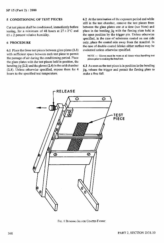
SP 15 (Part 2) :2000
5 CONDITIONING OF TEST PIECES
Cut test pieces shall be conditioned, immediately beforetesting, for a minimum of 48 hours at 27+ 2°C and65+ 2 percent relative humidity.
6 PROCEDURE
6.1 Place the three test pieces between glass plates (2.3)with sufficient space between each test piece to permitthe passage of air during the conditioning period. Placethe glass plates with the test pieces held in position, the
bending jig (2.2) and the gloves (2.4) in the cold chamber(2.1). Unless otherwise specified, expose them for 4
hours to the specified test temperature.
6.2 At the termination of the exposure period and whilestill in the test chamber, remove the test pieces frombetween the glass plates one at a time (see Note) andplace in the bending jig with the flexing plate held inthe open position by the trigger pin. Unless otherwisespecified, in the case of substrates coated on one sideonly, place the coated side away from the mandrel. Inthe case of double-coated fabrics either surface maybeevaluated unless otherwise specified.
NOTE— Gloves must be worn at all times when handling testpieces priorto makingthe bend test.
6.3 As soon as the test piece is in position in the bendingjig, release the trigger and permit the flexing plate tomake a free fall.
~RELEASEI
I
TESTPIECE
\
o0
FIG. 1 BENDINGJIGFORCOATEDFABRIC
. -
I
I
368 PART 2. SECTION D/31.10
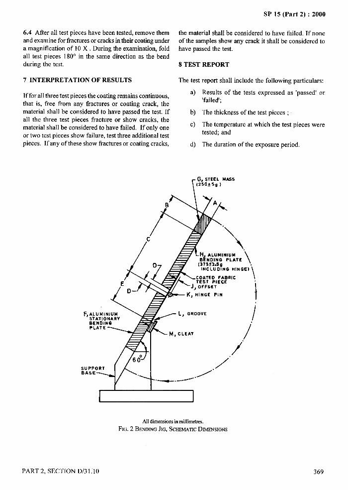
I
I .-
1 SP 15 (Part 2) :2000
6.4 After all test pieces have been tested, remove them the material shall be considered to have failed. If noneand examine for fractures or cracks in their coating under of the samples show any crack it shall be considered toa magnification of 10 X . During the examination, fold have passed the test.
L all test pieces 180° in the same direction as the bendF
during the test. 8 TEST REPORT
7 INTERPRETATION OF RESULTS The test report shall include the following particulars:
If for all three test pieces the coating remains continuous,a)
that is, free from any fractures or coating crack, thematerial shall be considered to have passed the test. If b)all the three test pieces fracture or show cracks, thematerial shall be considered to have failed. If only one
c)
or two test pieces show failure, test three additional testpieces. If any of these show fractures or coating cracks, d)
Results of the tests expressed as ‘passed’ or‘failed’;
The thickness of the test pieces ;
The temperature at which the test pieces weretested; and
The duration of the exposure period.
\
~, STEEL MASS[250t5g )
&
I I
Alldimensionsinmillimetres.FIG. 2 BENOINGJIG,SCHEMATICDIMENSIONS
PART 2, SECTION D/31.10
/
369
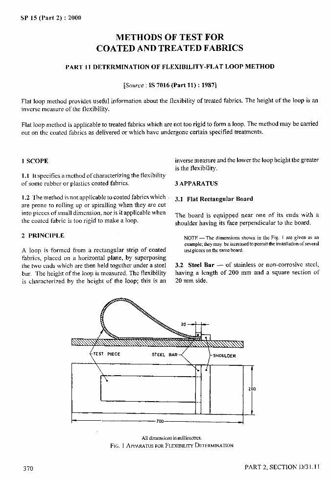
. &<
SP 15 (Part 2) :2000
METHODS OF TEST FOR
COATED AND TREATED FABRICS
PART 11 DETERMINATION OF FLEXIBILITY-FLAT LOOP METHOD
[Source: IS 7016 (Part 11): 1987]
Flat loop method provides useful information about the flexibility of treated fabrics. The height of the loop is aninverse measure of the flexibility.
Flat loop method is applicable to treated fabrics which are not too rigid to form a loop. The method maybe carried
out on the coated fabrics as delivered or which have undergone certain specified treatments.
1 SCOPE inverse measure and the lower the loop height the greateris the flexibility.
1.1 It specifies a method of characterizing the flexibilityof some rubber or plastics coated fabrics. 3 APPARATUS
1.2 The method is not applicable to coated fabrics which 3.1 Flat Re~tangU]ar Boardare prone to rolling up or spiraling when they are cutinto pieces of small dimension, nor is it applicable whenthe coated fabric is too rigid to make a loop.
2 PRINCIPLE
A loop is formed from a rectangular strip of coatedfabrics, placed on a horizontal plane, by superposingthe two ends which are then held together under a steelbar. The height of the loop is measured. The flexibilityis characterized by the height of the loop; this is an
370
/
The board is equipped near one of its ends with ashoulder having its face perpendicular to the board.
NOTE — The dimensions shown in the Fig. 1 are given as anexample;theymay be increasedto permit the installationof severaltest pieceson the same board.
3.2 Steel Bar — of stainless or non-corrosive steel,
having a length of 200 mm and a square section of20 mm side.
\
200
-700 -
All dimensionsin millimetres.
FIG. 1APPARATUSFORFLEXIBILITYDETERMINATION
PART 2, SECTION D/31.11
.—.1- -
I
.,4,
.—
3.3 Rule – Graduated in millimetres.
4 TEST PIECES
4.1 Shape and Dimensions
The test piece shall have the shape of a rectangle, 600mm long and 100 mm wide.
4.2 Number
Use three test pieces cut in the longitudinal directionand three test pieces cut in the transverse direction.
4.3 Sampling
The test pieces shall be taken so that their outside edgesare at a minimum distance of 100 mm from the edges ofthe coated part. They shall not be taken at a distanceless than 1000 mm from the ends of the coated part orat a location having a fold or an apparent defect.
5 TIME INTERVAL BETWEEN MANUFACTUR-ING AND TESTING
5.1 For all purposes, the minimum time betweenmanufacturing and testing shall be 16 h.
5.2 For non-product tests, the maximum time between
manufacturing and testing shall be 4 weeks and for
evaluations intended to be comparable, the tests, as faras possible, should be carried out after the same timeinterval.
5.3 For product tests, whenever possible, the timebetween manufacturing and testing should not exceed3 months. In other cases, tests shall be made within2 months of the date of receipt by the customer.
6 CONDITIONING OF TEST PIECES
The test pieces shall be conditioned at 27 + 2°C and65 + 2 percent relative humidity for at least 24 h prior
to testing. To avoid any deformation of the test pieces,they shall be placed, during conditioning, on a horizontalsurface, the face that is to form the outside of the loopbeing turned upward.
NOTE — Different results may be obtained for differentconditioningatmospl]ere.
7 PROCEDURE
7.1 Powder the surface of the board evenly with zincstearate or French chalk. Holding the ends of the test
SP 15 (Part 2) :2000
piece between the fingers, place it on the board so that
one side rests on the board and one end is against theshoulder (the choice of the side depends on the use ofthe product; it maybe subject to agreement between the
purchaser and the supplier; the test may also be repeatedafter having reversed the test piece side for side).
7.2 Bring the other end onto the first end (so as to form
a loop), pressing it also against the shoulder. Place thesteel bar on the superimposed ends. Keep the test piecein this position for 5 minutes.
7.3 Measure, with the rule, the maximum heights of
the two edges of the loop for each of the test pieces with
respect to the board.
8 EXPRESSION OF RESULTS
8.1 For each of the two directions there are three testpieces.
8.2 For each test piece cut in the longitudinal direction,
express in millimetres the maximum height of each ofthe two edges of the loop formed. Take the arithmetic
mean of the six values obtained as the result for the
longitudinal direction.
8.3 Repeat the procedure desc;ibed in 8.2 for test pieces
cut in the transverse direction.
9 TEST REPORT
The test report shall include the following information:
a) indication of reference to the side(s) on which
the results have been obtained;
b) each individual value obtained;
c) the arithmetic mean of the results for each test
piece;
i)
ii)
for test pieces cut in the longitudinal
direction;
for the test pieces cut in the transverse
direction;
d) the condition of the test piece subjected to
testing; and
e) whether the test was conducted on coated
fabric as delivered or after it had undergone
specified treatments (give details).
__+q
4
it..,
PART 2. SECTION D/31.1 I
/
371
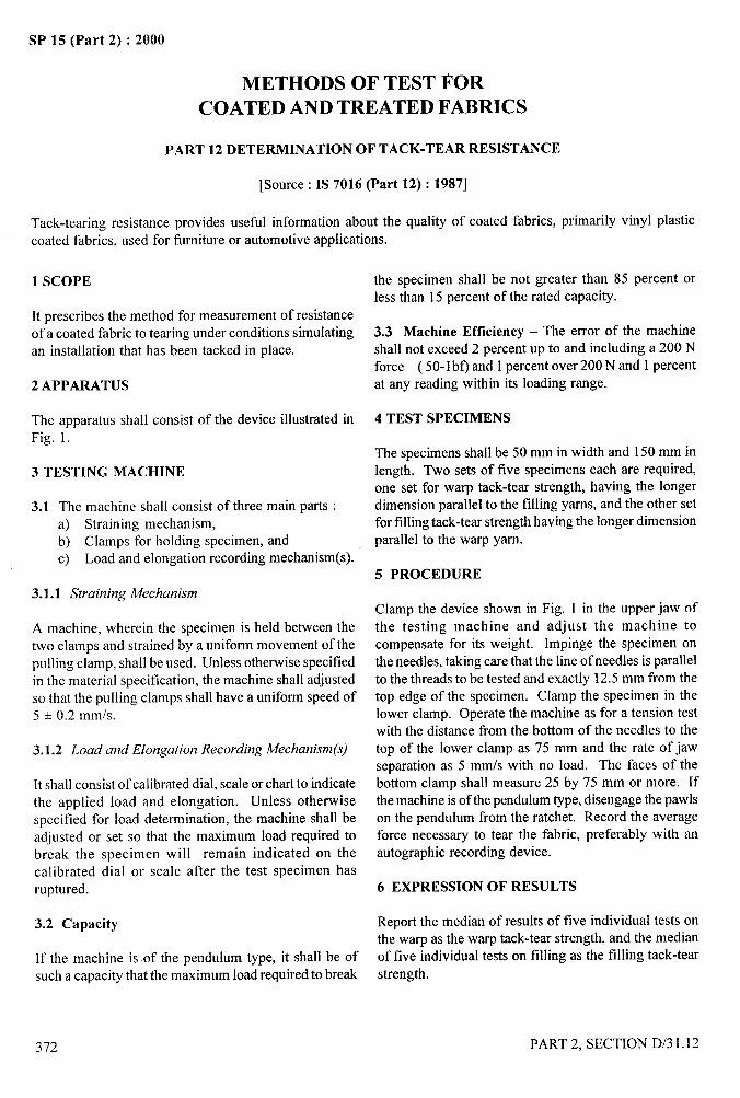
SP 15 (Part 2) :2000
METHODS OF TEST FOR
COATED AND TREATED FABRICS
PART 12 DETERMINATION OF TACK-TEAR RESISTANCE
[Source : IS 7016 (Part 12): 1987]
Tack-tearing resistance provides usefi.d information about the quality of coated fabrics, primarily vinyl plastic
coated fabrics, used for furniture or automotive applications.
1 SCOPE
It prescribes the method for measurement of resistanceof a coated fabric to tearing under conditions simulatingan installation that has been tacked in place.
2 APPARATUS
The apparatus shall consist of the device illustrated inFig. 1.
3 TESTING MACHINE
3.1 The machine shall consist of three main parts :a) Straining mechanism,
,b) Clamps for holding specimen, andc) Load and elongation recording mechanism(s).
3.1.1 Straining Mechanism
A machine, wherein the specimen is held between thetwo clamps and strained by a uniform movement of thepulling clamp, shall be used. Unless otherwise specifiedin the material specification, the machine shall adjustedso that the pulling clamps shall have a uniform speed of5 + 0.2 mm/s.
3.1.2 Load and Elongation Recording Mechanism(s)
Itshall consist of calibrated dial, scale or chart to indicatethe applied load and elongation. Unless otherwisespecified for load determination, the machine shall beadjusted or set so that the maximum load required tobreak the specimen will remain indicated on thecalibrated dial or scale after the test specimen hasruptured.
3.2 Capacity
If the machine is of the pendulum type, it shall be ofsuch a capacity that the maximum load required to break
the specimen shall be not greater than 85 percent orless than 15 percent of the rated capacity.
3.3 Machine Efficiency – The error of the machineshall not exceed 2 percent up to and including a 200 Nforce ( 50-1 bf) and 1 percent over 200 N and 1 percentat any reading within its loading range.
4 TEST SPECIMENS
The specimens shall be 50 mm in width and 150 mm inlength. Two sets of five specimens each are required,one set for warp tack-tear strength, having the longerdimension parallel to the tilling yams, and the other setfor filling tack-tear strength having the longer dimensionparallel to the warp yam.
5 PROCEDURE
Clamp the device shown in Fig. 1 in the upper jaw ofthe testing machine and adjust the machine tocompensate for its weight. Impinge the specimen on
the needles, taking care that the line of needles is parallelto the threads to be tested and exactly 12.5 mm from thetop edge of the specimen. Clamp the specimen in thelower clamp. Operate the machine as for a tension testwith the distance from the bottom of the needles to thetop of the lower clamp as 75 mm and the rate of jawseparation as 5 mm/s with no load. The faces of thebottom clamp shall measure 25 by 75 mm or more. Ifthe machine is of the pendulum type, disengage the pawlson the pendulum from the ratchet. Record the averageforce necessary to tear the fabric, preferably with anautographic recording device.
6 EXPRESSION OF RESULTS
Report the median of results of five individual tests onthe warp as the warp tack-tear strength, and the medianof five individual tests on filling as the filling tack-tearstrength.
—---;
372
/
PART 2, SECTION D/3 1.12
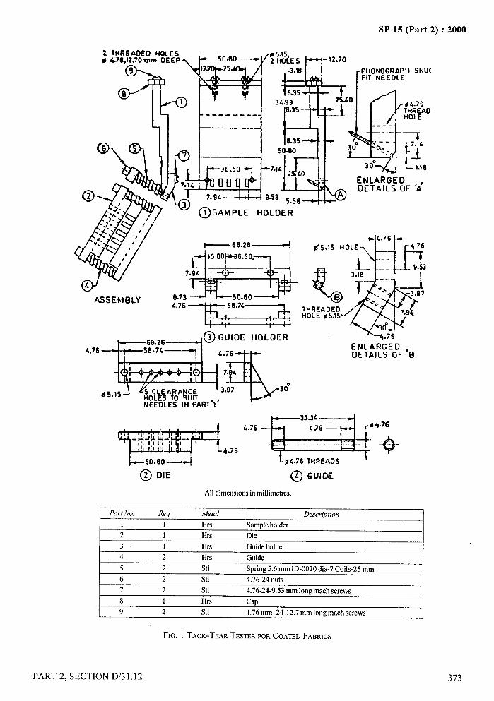
SP 15 (Part 2) :2000
2 lHREADEO HOLES o0 4.76,12.70 mm OEEP *50.80 ~ /2
%~ .$?
9 12.7 25.4
8 ‘81
~
----- ---
r~ K,& :
7
7.
7.14
;s0$
\f4 7“9’ 9.s
‘$tiz=iiASSEMBLY 8.73 ~ ‘ L50.804 ‘
‘“’’nz=il=l
‘“’’m&:e
NEEOLES IN PART’! ‘
PHONOGRAPH- SNU(FIT NEEOLE
&&76
$5.1S HOLE\ t-
%
,&’ :;j,
--.
? e.. ._t
B“3,97
-*..IHREAOEO>HOLE # 5.1S 7.94
~(30‘f076
ENLARGEOOETAII.S OF ‘B
wJ+ ‘H’;’L76’”’6+!+24’11111111111I*&
50060---~
@ DIE @ GUIO~
-@
All dimensionsin millimetres.
Part No. Req Metal Description
1 1 Hrs Sampleholder2 1 Hrs Die3 1 Hrs Guideholder4 2 Hrs Guide5 2 Stl Spring 5.6 mm ID-0020dia-7 Coils-25 mm6 2 Stl 4.76-24 nuts
7 2 Stl 4.76-24-9.53mm long math screws8 1 Hrs Cap9 2 Stl 4.76 mm -24-12.7mm long math screws
FIG. 1 TACK-TEARTESTERFORCOATEDFABRICS
PART 2, SECTION D/31.12
/
373
II
I

SP 15 (Part 2) :2000
METHODS OF’ TEST FOR COATED AND TREATED FABRICS
PART 13 DETERMINATION OF CRUSH RESISTANCE
[Source : IS 7016 (Part 13): 1987]
1 SCOPE
1.1 It prescribes a method for determining the crush
resistance of fabrics coated with rubber or plastics.
1.2 The method is applicable particularly to diaphragmmaterial cut from coated fabrics.
2 OUTLINE OF THE METHOD
The coated fabric is subjected to a controlled loadapplication over a known area until the fabric is
crushed.
3 APPARATUS
3.1 Bast Plate – Having the dimensions shown in Fig. 1
3.2 Load Button Assembly – Having the dimensionsshown in Fig. 2.
b
100
All dimensionsin millimetres,
FIG. 1BASEPLATE
3.3 Compression Testing Machine
Having a speed of approximately 0.08 mm/s.
3.3.1 Any other type of machine that will meet thisrequirement may also be used. For example, a platformscale equipped with a yoke over the platform and ahand-operated screw to apply the force will serve if itconforms to the requirements prescribed for accuracyand speed.
3.3.2 The load source shall have a total capacity of atleast 5400 N.
3.4 Force-Recording Mechanism
A calibrated dial with a maximum pointer, or a strip-
chart to indicate force required to crush the fabric.Unless otherwise specified for force determination, themachine shall be so adjusted that the maximum forcerequired to crush the test piece may be readily detectedby the maximum pointer or read from the strip-chart.The error of the machine shall not exceed 2 percent upto and including 200 N force and 1 percent over 200 Nforce at any reading within the loading range.
4 TEST PIECES
The test pieces shall be at least 50 mm wide and 200
mm long. At least three test values shall be obtained
from each sample.
5 TIME INTERVAL BETWEEN MANUFACTUR-ING AND TESTING
5.1 For all purpose, the minimum time betweenmanufacturing and testing shall be 16 h.
5.2 For non-product tests, the maximum time betweenmanufacturing and testing shall be 4 weeks and for
evaluations intended to be comparable, the tests, as far
as possible, should be carried out after the same timeinterval.
5.3 For product tests, whenever possible, the timebetween manufacturing and testing should not exceed
374 PART 2, SECTION D/31.13
I
IIi
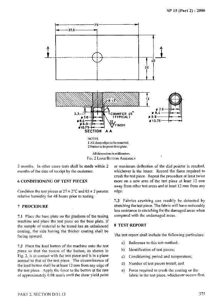
.-SP 15 (Part 2) :2000
L 75 4
—37.5
1
.?$~
1. -
+
A
.— -—- + ——-—- _l_40
20
1
SECTION A A
NOTES1All sharpedgesto be removed.2 Button to be press fit in plate,
All dimensionsin millimetres.1
FIG.2 LOAOBUTTONASSEMBLY
3 months. In other cases tests shall be made within 2months of the date of receipt by the customer,
6 CONDITIONING OF TEST PIECES
Condition the test pieces at 27 + 2°C and 65 + 2 percentrelative humidity for 48 hours prior to testing.
7 PROCEDURE
7.1 Place the base plate on the platform of the testingmachine and place the test piece on the base plate. If
the sample of material to be tested has an unbalanced
coating, the side having the thicker coating shall befacing upward.
7.2 Place the load button of the machine onto the testpiece so that the recess of the button, as shown inFig. 2, is in contact with the test piece and is in a planenormal to that of the test piece. The circumference ofthe load button shall beat least 12 mm from any edge ofthe test piece. Apply the force to the button at the rateof approximately 0.08 mm/s until the shear yield point
..
or maximum deflection of the dial pointer is reached,whichever is the lesser. Record the force required tocrush the test piece. Repeat the procedure at least twicemore on a new area of the test piece at least 12 mm :,,,away from other test areas and at least 12 mm from anyedge.
7.3 Fabrics crushing can readily be detected bystretching the test piece. The fabric will have noticeablyless resistance to stretching for the damaged areas whencompared with the undamaged areas.
8 TEST REPORT
The test report shall include the following particulars:
a) Reference to this test method;
b) Identification of test pieces;
c) Conditioning period and temperature;
d) Number of test pieces tested; and
e) Force required to crush the coating or thefabric in the test piece, whichever occurs first.
PART 2, SECTION D/31.13 375

SP 15 (Part 2) :2000~ ...
METHODS OF TEST FOR COATED AND TREATED FABRICS ~ ___
PART 14 LOW-TEMPERATURE IMPACT TEST
[Source : IS 7016 (Part 14): 1987]
This prescribes a method for evaluation of rubber materials or fabrics coated therewith subjected to low temperatureflexing with impact under well-defined conditions of striker speed. The response is largely dependent of effects oflow temperatures, such as, crystallization, incompatibility of plasticizer or the inherent short term behaviollr of the /
material itself. Data obtained by the method may be used to predict the product behaviour in applications wherethe conditions are similar to those specified in the method.
I
The method has been found useful for specification and development purposes, but it does not necessarily indicatethe lowest temperature at which the material may be used.
1 SCOPE
It prescribes procedure for determining the lowesttemperature at which fabrics coated with rubber orplastics shall not exhibit fractures or coating cracks whensubjected to specific impact conditions.
2 APPARATUS,. -
2.1 Test Piece Clamps and Striking Arm
The test piece clamps shall be designed to hold the testpiece or pieces as a cantilever beam. Each individualtest piece shall be held firmly and securely in the clamps.The striking edge shall move relative to the test piece(s)along a trajectory normal to the upper surface at a linearspeed of 1.8 to 2.1 m/s at impact and during at least thefollowing 6 mm of travel. In order to maintain thisvelocity consistently within the heat-transfer medium,the striking arm shall be positively driven. It may benecessary in some cases to reduce the number of testpieces tested at one time (see Annex A).
2.1.1 The striking edge shall have a radius of 1.6 + 0.1mm. The striking arm and test piece clamps shall havea clearance at and immediately following impact inaccordance with the dimensions listed in Table 1.
Table 1 Clearance of Striking Arm andTest Piece Clamps
Thickness of test Required Clearance, mmPieces, mm
1.65102.15 6.4 +0.3
1.05to 1.64 5.7+ 0.3
o.55to 1.04 5.2+ 0.3
o.lotoo.54 4.8+ 0.3
NOTES1 The dimensionalrequirementsmaybe obtainedby fabricatinganadjustment plate or individual plates to tit the test piece holderilhrstrated inFig. 1.2 Apparatusfor this test may have any type of activation, providedthat it meetsthe dimensionalandvelocityrequirementsgiven aboveand in 2. If the striker is electrically driven, a means of controllingthe voltage may be needed to control the speed when testing lightgaugematerial.
-COATEOSURFACE TO BEEVALUATEO
STRIKING EOGE CLAMP
I RADIUS 1-6* 0.1
h
PIECE
~EE I&&TABLE
15f5 ~6min.
All dimensionsin millimetres.
FIG. 1 TESTPIECEHOLDERANDSTRIKER
2.2 Insulated Tank
2.3 Heat Transfer Medium
Any liquid heat-transfer medium that remains fluid atthe test temperature and which does not appreciablyaffect the materials being tested may be used.
CAUTION — Where a flammable or toxic solvent isused as the cooling medium, the customary precautionsin handling, such as
2.3.1 Methanol ismedium for rubber.
material shall be exercised.
the recommended heat-transfer
1
I
I
I
I
/
376 PART 2, SECTION D/3 1.14

I
I NOTE — The following materials have beeo used dowo to theindirated, temperatures:
I Dow Corning 200 fluids:a) Kinematic viscosity 5 mm2/s – 60°Cb) Kinematic viscosity 2 mm2/s – 76°CMethanol – 90°c
Dichlorodifluoromethane – 120”C
~ When dichlorodifluoromethane refrigerant is used, itshall be cooIed below its boiling temperature of – 29.8°CIbefore being transferred from the cylinder to the tank of
I the testing machine.
(2.4 Stirrer – to provide thorough circulation of theheat-transfer medium.
2.5 Temperature Control (Automatic or Manual) –for controlling the temperature of the heat-transfer.medium to within + 0.5°C of the desired temperature.
.,2.5.1 Powdered solid carbon dioxide (dry ice), liquidnitrogen or liquid carbon dioxide are recommended forlowering the temperature. An electric immersion heateris required for raising the temperature.
2.6 Thermocouple
With associated temperature indicator graduated inl°C divisions and having a range suitable for thetemperature at which the tests are to be made. Thethermocouple shall be constructed ofcopper-constantanwire between 0.2 mm and 0.5 mm in diameter and shallbe fusion-bounded at the junction. It shall be located asnear the test piece as possible.
NOTE — A thermometer may be used if it is shown to be inagreementwith the specifiedthermocouple,
3 TEST PIECES
3.1 The test piece shall be die punched. It shall be6.4 + 0.5 mm wide. All test pieces shall be cut with thelonger dimensions parallel to the lengthwise directionof the coated fabric unless otherwise specified.
3.2 A minimum of 6 mm of the test piece shall be heldin the clamps, and the length extending from the clampshall be 25 + 5 mm.
NOTE — Sharp dies shall be used in tbe preparationof test piecesfor this test ifrcl iable results are to be obtained. Light boning ofthe cutting edges with ajeweller’s honing stone maybe carried outdaily.
SP 15 (Part 2) :2000
4 TIME INTERVAL BETWEEN MANUFACTUR- .. =ING AND TESTING
4.1 For all test purposes, the minimum time between ~......manufacturing and testing shall be 16 h. A
,.,(&
4.2 For non-product tests, the maximum time between
manufacturing and testing shall be 4 weeks and forevaluations intended to be comparable the test, as far aspossible, should be carried out after the same time-interval.
4.3 For product tests, whenever possible, the time
between manufacturing and testing should not exceed3 months. In other cases, tests shall be made within2 months of the date of receipt by the customer.
5 CONDITIONING OF TEST PIECES
5.1 The test pieces shall be conditioned at 27+ 2°Cand 65+ 2 percent relative humidity for at least 3 h priorto testing.
6 PROCEDURE
6.1 Prepare the tank (2.2) and bring the apparatus tothe desired temperature. This may be accomplished byplacing a suitable amount of solid carbon dioxide(dry ice) in the tank and slowly adding the heat-transfermedium until the tank is tilled within 50 mm of the top.During the test, the temperature of the bath may bemaintained constant by judicious addition of smallquantities of dry ice.
\:
NOTE— TIEdesiredtemperature may also be obtained by tillingthetankwiththe heat-transfermediumand loweringthe temperatureby the addition of liquid carbon dioxide control~d by a solenoidactuatedwithan associatedtemperaturecontrol. Wheretemperaturesbelow that obtainable with dry ice or liquid carbon dioxide arerequired, liquid nitrogenmay be used.
6.2 Determine the thickness of the test pieces in accordancewith the method prescribed in IS 7016 (Part 1) : 1982‘Methods of test for coated and treated fabrics:
Part 1 Determination of roll characteristics ~ir.st
revision) ’given in Section D/31.1.
6.3 Mount the test pieces in their holder and immersethem for 3.0 t 0.5 min at the desired temperature. Theside to be evaluated shall face toward the striking armunless otherwise specified.
6.4 After immersion for the specified time at the testtemperature, record the temperature and deliver a singleimpact.
PART 2. SECTION D/3 1.14 377
II
I I
SP 15 (Part 2) :2000
6.5 For each test, check the speed of the striker, which 7 TEST REPORT
shall be between 1.8 and 2.1 m/s (see Annex A).The test report shall
6.6 After removing the test pieces from the tank,examine each test piece to determine whether or not ithas failed. Failure is defined as any fracture or crackvisible in the coating when examined under a5 X magnifier. Bend the test piece to an angle of 180°around a 6 mm diameter mandrel in the same directionas the bend caused by the impact prior to examining itunder the 5 X magnifier.
6.7 Use new test pieces for each test temperature.
NOTE — Forroutine testing of all coated fabrics, subject the fivetest pieces to the impact test at a specified temperature as stated inthe relevantmaterial specification.
6.8 For compliance with this method, no test pieceshall fail at the specified temperature.
a)
b)
c)
d)
e)
f)
dh)
j)
k)
include the following particulars:
Reference to this test method;
Identification of the coated fabric;
Temperature at which the test pieces weretested;
Type of testing apparatus used;
Conditioning temperature, humidity andperiod;
Length of time test pieces were immersed;
Number of test pieces tested;
Speed of striker at impact;
Behaviour of individual test pieces; and
Thickness of the coated fabric.
—-+-q,,
d
.$
I
I
I
. ..
1’
iii
I
378 PART 2, SECTION D/31.14
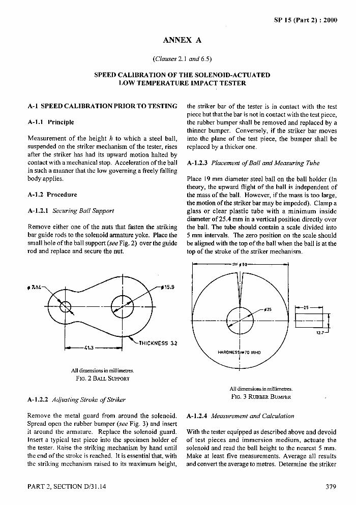
.4-
ANNEX A
(Clauses 2.1 and 6.5)
SPEED CALIBRATION OF THE SOLENOID-ACTUATEDLOW TEMPERATURE IMPACT TESTER
A-1 SPEED CALIBRATION PRIOR TO TESTING
A-1.l Principle
Measurement of the height h to which a steel ball,suspended on the striker mechanism of the tester, risesafter the striker has had its upward motion halted bycontact with a mechanical stop. Acceleration of the ballin such a manner that the low governing a freely fallingbody applies.
A-1.2 Procedure
A-1.2.1 Securing Ball Support
Remove either one of the nuts that fasten the strikingbar guide rods to the solenoid armature yoke. Place thesmall hole of the ball support (see Fig. 2) over the guiderod and replace and secure the nut.
# 7.l& p15.9
1--,,,, ~ ‘THICKNESS
All dimensionsin millimetres,
FIG.2 BALL SUPPORT
A-1 .2.2 Acjiusting Stroke of Striker
3.2
Remove the metal guard from around the solenoid.Spread open the rubber bumper (see Fig. 3) and insertit around the armature. Replace the solenoid guard.Insert a typical test piece into the specimen holder ofthe tester. Raise the striking mechanism by hand untilthe end of the stroke is reached. It is essential that, withthe striking mechanism raised to its maximum height,
..—SP 15 (Part 2) :2000
—-!-,
the striker bar of the tester is in contact with the testpiece but that the bar is not in contact with the test piece,the rubber bumper shall be removed and replaced by athinner bumper. Conversely, if the striker bar movesinto the plane of the test piece, the bumper shall bereplaced by a thicker one.
A-1.2.3 Placement of Ball and Measuring Tube
Place 19 mm diameter steel ball on the ball holder (Intheory, the upward flight of the ball is independent ofthe mass of the ball. However, if the mass is too large,the motion of the striker bar maybe impeded). Clamp aglass or clear plastic tube with a minimum insidediameter of 25.4 mm in a vertical position directly overthe ball. The tube should contain a scale divided into
5 mm intervals. The zero position on the scale shouldbe aligned with the top of the ball when the ball is at thetop of the stroke of the striker mechanism.
~“’’”——————l
a25
-—.
12.7
All dimensionsin millimetres.
FIG. 3 RUBBERBUMPER
A-1.2.4 Measurement and Calculation
With the tester equipped as described above and devoidof test pieces and immersion medium, actuate thesolenoid and read the ball height to the nearest 5 mm.Make at least five measurements. Average all resultsand convert the average to metres. Determine the striker
PART 2. SECTION D/31.14 379
/
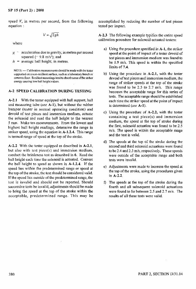
SP 15 (Part 2) :2000
speed V, in metres per second, from the followingequation :
where
g = acceleration due to gravity, in metres per secondsquared (= 9.8 m/s2); and
h = average ball height, in metres.
NOTE— Calibrationmeasurementsshouldbe madewith the testersupported on a non-resilient surface, such as a laboratory bench orconcretefloor. Resilientmountingitend to absorbsomeofthe strikerenergy causing low ball height values.
A-2 SPEED CALIBRATION DURING TESTING
A-2. 1 With the tester equipped with ball support, balland measuring tube (see A-l), but without the rubberbumper (tester in normal operating condition) anddevoid of test pieces and immersion medium, actuatethe solenoid and read the ball height to the nearest5 mm. Make ten measurements. From the lowest andhighest ball height readings, determine the range instriker speed, using the equation in A-1.2.4. This rangeis termed range of speed at the top of the stroke.
A-2.2 With the tester equipped as described in A-2.1,but also with test piece(s) and immersion medium,conduct the brittleness test as described in 6. Read theball height each time the solenoid is actuated. Convertthe ball height to speed as shown in A-1.2.4. If the
speed lies within the predetermined range or speed atthe top of the stroke, the test should be considered valid.If the speed lies outside of the predetermined range, thetest is invalid and should not be reported. Shouldsuccessive tests be invalid, adjustments should be madeto bring the speed at the top of the stroke within theacceptable, predetermined range. This may be
accomplished by reducing the number of test piecestested per impact.
A-2.3 The following example typifies the entire speedcalibration procedure for solenoid-actuated testers:
a)
b)
c)
d)
e)
9
Using the procedure specified in A-1, the strikerspeed at the point of impact of a tester devoid oftest pieces and immersion medium was found tobe 1.9 m/s. This speed is within the specifiedlimits of 7.4.
Using the procedure in A-2.1, with the testerdevoid of test pieces and immersion medium, therange of striker speeds at the top of the strokewas found to be 2.5 to 2.7 m/s. This rangebecomes the acceptable range for this series oftests. The acceptable range should be establishedeach time the striker speed at the point of impactis determined (see A-l).
Using the procedure of A-2.2, with the testercontaining a test piece(s) and immersionmedium, the speed at the top of stroke duringthe first, solenoid actuation was found to be 2.5m/s. The speed is within the acceptable rangeand the test is valid.
The speeds at the top of the stroke during thesecond and third solenoid actuations were foundto be 2.4 and 2.3 mfs, respectively. These speedswere outside of the acceptable range and bothtests were invalid.
Adjustments were made to increase the speed atthe top of the stroke, using the procedures givenin A-2.2.
The speeds at the top of the stroke during thefourth and all subsequent solenoid actuationswere found to lie between 2.5 and 2.7 m/s. Theresults of all these tests were valid.
—.-
i-
380 PART 2, SECTION D/31.14
A-
/
SP 15 (Part 2) :2000
SECTION E
BIOCHEMICAL TESTS

As in the Original Standard, this Page is Intentionally Left Blank
\
I
SP 15 (Part 2) :2000
DETECTION AND ESTIMATION OF DAMAGE IN COTTON YARN,CORDAGE AND FABRICS DUE TO MICRO-ORGANISMS
(Source : IS 1815:1985 and IS 1316: 1984)
Cotton yarn cordage are liable to be attacked and damaged by micro-organisms, such as bacteria and fungi, whilein transit, in storage or in use. The deterioration is promoted by climatic conditions prevalent in tropical andsubtropical countries.
Moisture is essential for the development and growth of micro-organisms, the amount of moisture required beingdependent upon the type of organism. Thus fungi usually develop when the relative humidity of the environmen~approaches about 75 percent, and the growth is rapid when the relative humidity is above 85 percent. Bacterial, onthe other hand, are active only when the substrate on which they are present is itself wet.
Fungi may appear as tine downy growth or as dark spots or stains causing discoloration of yam or cordage as thecase may be. The isolated regions of mould growth may show considerable tendering while the rest of the material
(except when not weathered outdoors) may indicate little or no tendering. If the yam or cordage had been incontact with soil or had been contaminated with it and then exposed to dampness, the entire material may showrapid and uniform tendering.
The degree of growth of micro-organisms as well as their tendering effect may differ widely even in the immediate
neighboring areas in the yam or cordage. It is, therefore, not feasible to submit the results of tests prescribed inthis test method to statistical analysis.
1 SCOPE
1 It prescribes a method for the detection and estimationof damage in cotton yam, cordage and fabrics due to
Imicro-organisms.
2 SAMPLING
2.1 Lot
The quantity of cotton yam, cordage or fabric purportedto be of one definite type and quality delivered to a buyeragainst one despatch note shall constitute a lot.
2.2 Sample for the test shall be selected so as to berepresentative of the lot. Samples drawn in accordance
1with the material specification or as agreed to betweenthe buyer and the seller shall be taken as representativeof the lot.
t 2.3 The sample shall be first visually examined againstlight for the presence of microbial growth like isolateddark portions, stains or discoloration; all the portionsshowing microbial growth shall be clearly marked.
2.4 The sample shall also be examined under anultraviolet lamp having a Blackwoodfilter with peakoutput at 365 mm for the presence of any flourescentspots which shall be clearly marked.
NOTE— The presenceoffluorcscence is always not related to themicrobialattackor the absenceof it does not excludethe possibilityofmicrobkalattack.
3 TEST SPECIMENS
From the marked portions of the yam or cordage draw.,
at random 10 pieces each not less than 10 cm long. In
case of fabrics, draw at random 10 test specimens each )!2.5 cm x 2.5 cm in size. These shall constitute the test
specimens for the purpose of 5.1.1, 5.1.2 and 6.1.1.
Keep the test specimens in a humid chamber (see Note)
with relative humidity above 85 percent at room
temperature for 8 to 10 days. (For a humid chamber a
large desiccator with water kept at the bottom may
suffice.).
NOTE- If the marked portion as in 2.3 and 2.4 of the sample inthe lot is showing visible patches of stains or discoloration, tbespecimensdrawnas in 3 may be directly studied as in 5.1.1 withoutkeepingin a humid chamber.
4 REAGENTS
4.1 Quality of Reagents
4.1.1 Unless specified otherwise, ‘pure chemicals’ shall
be employed in the tests and distilled water shall be used
where the use of water as a reagent is intended.
PART 2. SECTION E/l 383
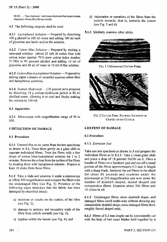
r,;
SE’ 15 (Part 2) :2000
NOTE — ‘Purechemicals’shallmeanchemicatsthat donot containimpuritieswhich affect the test resaks.
4.2 The following reagents shall be used.
4.2.1 Lactophenol Solution — Prepared by dissolving100 g phenol in 100 ml water and adding 100 ml eachof glycerine and lactic acid to the solution.
4.2.2 Cotton Blue Solution — Prepared by making a
saturated solution (about 25 ml) of cotton blue (oldcolour index number 707) (new colour index number511 90) in 95 percent alcohol and adding 10 ml ofglycerine and 80 ml of water to 10 ml of this solution.
4.2.3 Cotton Blue-Lactophenol Solution — Prepared bymixing equal volumes of saturated aqueous cotton blueand lactophenol solutions.
4.2.4 Sodium Hydroxide —(18 percent m/v) preparedby dissolving 18 g sodium hydroxide pellets in 80 mldistilled water, allowing it to cool and finally makingthe volume to 100 ml.
4.3 Apparatus
4.3.1 Microscope with magnitieation range of 50 to
500.
5 DETECTION OF DAMAGE
5.1 Procedure
5.1.1 Unravel five to six yarns from the test specimensas drawn in 3.1. Tease them gently on a glass slide toseparate individual fibres. Treat the tibres with a fewdrops of cotton blue-lactophenol solution for 1 to 2minutes. Remove the colour tlom the surface of the fibresby treating them with lactophenol solution. Prepare atleast 10 slides from these tibres.
5.1.2 Take a slide and examine it under a microscopeat 100 to 500 magnification and compare the fibres withthe undamaged fibre (see Fig. 5). Presence of thefollowing signs indicates that the fabric has beendamaged by microbial attack:
a)
b)
c)
384
incisions or cracks on the cuticle, of the fibre(see Fig. 2);
.. . .damage to primary and secondary walls Otfibre from cuticle inwards (see Fig. 3);
hyphae within the lumen (see Fig. 4); and
the
d)
5.1.3
indentation or serrations of the tibres fi-om thecuticle inwards, that is, towards the lumen(see Fig. 5 and 6).
Similarly examine other slides.
tFIG. 1 UNDAMAGEDCOnON FmRE
FIG. 2 COTTONFIBRESHOWINGINCISIONSOR
CRACKSONITSCUTICLE
6 EXTENT OF DAMAGE
6.1 Procedure
6.1.1 Extrusion Test
Take one test specimen as drawn in 3 and prepare theindividual fibres as in 5.1.1. Take a clean glass slide
and place a drop of 18 percent NaOH on it. Place abundle of fibres on a linoleum pad and cut off a smallportion of the fibres approximately 0.2 mm in lengthwith a sharp blade. Immerse the cut fibres in the alkalifor about 60 seconds and examine under themicroscope at 250 magnification and note down thenumber of dumbell shaped, funnel shaped andextrusionless tibres. Examine about 300 fibres and10 slidewin all.
6.1.2 Undamaged fibres show dumbell shape, anddamaged tibres swell width-wise without showing anycharacteristic dumbell shape; some damaged fibres showroughly fine] shaped ends.
6.1.3 Fibres of 0.2 mm length can be conveniently cutwith the help of two razor blades held together by a
—
I
---
I
Iil
.,
‘1PART 2, SECTION E/l
i,
!

SP 15 (Part 2) :2000
FIG. 3 COTTONFIBRESHOWINGDAMAGETOrrsPmMARY
AND SECONDARYWALLSFROMTHECUTICLEINWAROS
FIG.4 COTTONFraRESHOWINGFUNGALINFECTION-
HYPHAEANDSPORESINSIDEANDLUMEN
FIG.6 COTrONFIBRESHOWINGSEVERE
BACTERIALDAMAGE
FIG.5 COTTONFmmESHOWINGMODERATE
BACTERIALDAMAGE~uali~ ~gu,e _ (a) ~ (b) ~@
123
holder and then cutting the specimen, the fibres inbetween the two blades to be taken for examination.
6.1.4 Mechanically damaged fibres also do not showany characteristic dumbell shape and may add to thedamage due to microbial attack, but their contributionto damage is negligible.
6.2 Calculate the percentage of dumbell shaped (a)funnel shaped (b) and extrusionless fibres (c) asexamined in 6.1.1. Obtain the quality figure as follows:
6.2.1 If a quality figure in 6.2 is less than 75, thenreport the sample as damaged. The quality figure mayalso include damage due to mechanically damagedfibres.
7 REPORT
The report shall include the following information:a) Type of material,b) Damaged/undamaged, andc) Number of specimens tested.
..——q
.
( PART 2. SECTION E/l 385
II1?
I
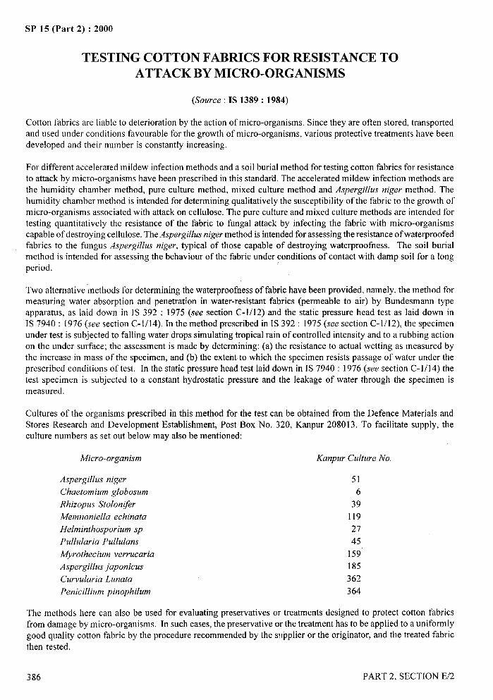
.—-
SP 15 (Part 2) :2000
TESTING COTTON FABRICS FOR RESISTANCE TOATTACK BY MICRO-ORGANISMS
(Source : IS 1389: 1984)
Cotton fabrics are liable to deterioration by the action ofmicro-organisms. Since they are often stored, transportedand used under conditions favorable for the growth of micro-organisms, various protective treatments have beendeveloped and their number is constantly increasing.
For different accelerated mildew infection methods and a soil burial method for testing cotton fabrics for resistanceto attack by micro-organisms have been prescribed in this standard. The accelerated mildew infection methods arethe humidity chamber method, pure culture method, mixed culture method and Aspergillus niger method. Thehumidity chamber method is intended for determining qualitatively the susceptibility of the fabric to the growth ofmicro-organisms associated with attack on cellulose. The pure culture and mixed culture methods are intended fortesting quantitatively the resistance of the fabric to fungal attack by infecting the fabric with micro-organismscapable of destroying cellulose. The Aspergillus niger method is intended for assessing the resistance of waterproofedfabrics to the fungus Aspergillus niger, typical of those capable of destroying waterproofness. The soil burialmethod is intended for assessing the behaviour of the fabric under conditions of contact with damp soil for a longperiod.
Two alternative ‘methods for determining the waterproofness of fabric have been provided, namely, the method formeasuring water absorption and penetration in water-resistant fabrics (permeable to air) by Bundesmann type
apparatus, as laid down in IS 392 : 1975 (see section C-1/12) and the static pressure head test as laid down inIS 7940: 1976 (see section C-1/14). In the method prescribed in IS 392: 1975 (see section C-1/12), the specimenunder test is subjected to falling water drops simulating tropical rain of controlled intensity and to a rubbing actionon the under surface; the assessment is made by determining: (a) the resistance to actual wetting as measured bythe increase in mass of the specimen, and (b) the extent to which the specimen resists passage of water under theprescribed conditions of test. In the static pressure head test laid down in IS 7940:1976 (see section C-1/14) the
test specimen is subjected to a constant hydrostatic pressure and the leakage of water through the specimen ismeasured.
Cultures of the organisms prescribed in this method for the test can be obtained from the Defence Materials andStores Research and Development Establishment, Post Box No. 320, Kanpur 208013. To facilitate supply, theculture numbers as set out below may also be mentioned:
Micro-organism Kanpur Culture No.
Aspergillus niger
Chaetomium globosum
Rhizopus Stolonlfer
A4emnoniella echinata
Helminthosporium sp
Pullularia Pullulans
Myrothecium verrucaria
Aspergillus japonicus
Curvularia Lunata
Penicillium pinophilum
51
6
39
119
27
45
159
185
362
364
The methods here can also be used for evaluating preservatives or treatments designed to protect cotton fabricsfrom damage by micro-organisms. In such cases, the preservative or the treatment has to be applied to a uniformly
good quality cotton fabric by the procedure recommended by the svpplier or the originator, and the treated fabricthen tested.
386 PART 2, SECTION E/2
SP 15 (Part 2) :2000
1 SCOPE
It prescribes methods for evaluating cottonresistance to attack by micro-organisms.
fabrics for
12 ATMOSPHERIC CONDITIONS FORCONDITIONING AND TESTING
2.1 The tests shall be carried out under the conditionslaid down in the respective test procedures. However,the specimens for breaking load testing shallbe conditioned and tested in the standard atmosphereat 65 + 2 percent relative humidity and 27 + 2°Ctemperature (see IS 6359 : 1971 ‘Method of
1conditioning of textiles’).
1 2.2 When the specimens have been left in such anatmosphere for 24 hours in such a way as to expose, asfar as possible, all portions of the specimens to theatmosphere, they shall be deemed to have reachedmoisture equilibrium.
3 SAMPLING
3.1 Lot
The quantity of similar cotton fabric delivered to a buyer
against one despatch note shall constitute a lot.
3.2 Samples shall be drawn so as to be representative ofthe lot. Samples drawn in accordance with the materialspecification or as agreed to between the buyer and theseller shall be taken as representative of the lot.
3.3 Take a sufficiently long piece (see Note 1) fromeach sample selected and mark it to identify it as a testsample. Similarly take a sufficiently long piece fromthe basic fabric (see Notes 2, 3 and 4) and mark it toidentify it as the control sample.
NOTES
1 The total lengthof the test sampleswill dependontheirwidth,butit should be sufficient for the number of test specimens requiredfor 4.1,4 .2,4.3,4.4 and S.
2 The length of the control sample will depend on its width, but itshould be sofflcient forthe numberofcontrolspecimensrequiredfor4.1,4.2,4.3, and5.
3 Ifanauthenticsampleof thebasicfabricisnotavailable,a fabricsimilarinconstructionto theoneundertestandt’reefromsizeandfinish should be used.
4 [fit is known that the fabric under test has not beentreatedwith apreservative, a sufficiently long piece from a well-scoured cottonfabric shall be taken as the basic fabric. The mass/m2of this fabricshall not vary by more than 20 percent of the mass of the fabricunder test.
4
5 If information as to whether the fabric was treated with a _...-preservativecontaining copperor mercury or both is not available,the fabricshouldbetestedforthe presenceof copperand mercurybythe usual chemicaltests.
ACCELERATED MILDEW INFECTION ‘q
METHODS
4.1 Humidity Chamber Method
4.1.1 Apparatus
4.1.1.1 Humidity chamber – with inside measurements
70 cm x 80 cm x 70 cm, lined on the inside with a non-corrosive material, and provided with shelves,arrangements to maintain relative humidity of 98+2percent at 30+ 2°C and, preferably, a fan for aircirculation.
4.1.1.2 Petri dishes – 12, each 15 cm in diameter,without cover.
4.1.2 Test Organisms – Cultures of the followingorganisms:
a) Aspergillus niger,
b) Chaetomium globosum, ;
c) Rhizopus stolonl~er,
d) Memnoniella echinata,
e) Helminthosporium sp, and
t) Pulhdaria pulhdans. .
4.1.3 Procedure \\,,/’ ~
4.1.3.1 From the test samples, cut at random 6 test
specimens, each of size 10 cm x 5 cm, with their longersides parallel to warp threads.
4.1.3.2 Prepare, in the manner prescribed in Annex A,mixed suspension of the spores of the test organismsprescribed in 4.1.2.
4.1.3.3 Take 6 petri dishes and place I test specimen ineach dish. Inoculate each specimen (see 4.1.3.4) with2 ml of the mixed spore suspension. Lay the petri disheson the shelves and leave them for 14 days insi~e thehumidity chamber maintained at 98 + 2 percent relativehumidity and 30+ 2°C temperature. At the end of theperiod, remove the specimens and evaluate the degreeof fingal growth on each specimen in terms of ratingsas given in Table 1.
4.1.3.4 From the control sample, cut at random 6 controlspecimens, each of size 10 cm x 5 cm with their longer
PART 2. SECTION E/2 387
.—-SP 15 (Part 2) :2000
sides parallel to warp threads. Side by side with the teston test specimens, test the control specimens accordingto the procedure set out in 4.1.3.3 for test specimens.
Table 1 Degree of Fungal Growth
(Clauses 4.1.3.3 and4.4.3.3)
Symbolic State of Growth of Rating in Terms ofRating Micro-Organisms Resistance
(1) (2) (3)
— No growth Good
+ Slight growth (area of Fairgrowth lessthan one-fourth)
++ Moderate growth (area of Poorgrowth more than one-fourthbut less than hal~
+++ Heavy growth (area of growth Verypoor
more than halt)
4.1.3.5 The rating for the control specimens shall be‘very poor’, that is, the control specimens should show
heavy mould growth; if not, the test shall be consideredinconclusive and shall be repeated.
4.1.3.6 Report the rating in terms of resistance of thefabric under test to attack by micro-organisms.
4.2 Pure Culture Method
4.2.1 Apparatus
4.2.1.1 Petri dishes – 15, each 15 cm in diameter
4.2.1.2 Atomizer – 10-ml capacity.
4.2.2 Test Organism – Culture of Chaetomiumglobosurn.
NOTE — If the material under test has been treated with apreservative containing mercury or copper or both (see Note 5under 3.3). culture of Myrotlreciwn verrucaria should be usedinstead of ( ‘haetornium globosum.
4.2.3 Test Medium – Mix together the following in1000 ml of distilled water and sterilize with steam at apressure of 108 kPa (1.1 Kg/cmz) for 20 minutes :
Ammonium nitrate 3.00 g
Potassium dihydrogen 0.25 g
phosphate
Magnesium sulphate 0.25 g
Potassium ch Ioride 0.25 g
Agar-agar 5.00 g
NOTES1 Only pure chemicals shall be used for preparing the medium.‘Purechemicals’shallmean chemicalsthat do not containimpuritieswhich affectthe resultsof test.2 ThepH of the medium should be 6.4.
4.2.4 Procedure
4.2.4.1 From the test samples, cut at random 15 testspecimens, each of size 27 cm x 6.5 cm, with their longersides parallel to warp threads. Take 5 test specimens,condition them to moisture equilibrium in the standardatmosphere (see 2) and determine the breaking load ofeach specimen by the method prescribed in IS 1969:1968 ‘Method for determination of breaking load andelongation at break of woven textile fabrics ~irstrevision)’ (see Section B-3/6). Find the average of allthe values.
4.2.4.2 From the control sample, cut at random 10control specimens, each of size 27 cm x 6.5 cm. withtheir longer sides parallel warp threads. Take 5 controlspecimens, condition them to moisture equilibrium inthe standard atmosphere (see 2) and determine thebreaking load of each specimen by the method prescribedin IS 1969:1968. ‘Method for determination of breakingload and elongation at break of woven textile fabrics(fzrst revision)’ (see Section B-3/6) Find the average ofall the values.
4.2.4.3 Prepare, in the manner prescribed in Annex A,
suspension of the spores of the test organism prescribedin 4.2.2.
4.2.4.4 Out of the remaining 10 test specimens, take5 specimens.
4.2.4.5 Sterilize the specimens in the manner prescribedin Annex B and with sterile instruments. Transfer themto 5 sterile petri dishes, each containing 50 ml of thetest medium. Roll up the two ends of each specimen sothat about 13 cm of its central portion is left exposed.Inoculate the exposed portion of each specimen understerile conditions by spraying with 2 ml of the suspensionprepared as in 4.2.4.3 by means of the atomizer.Incubate the specimens for 14 days at 98+2 percentrelative humidity and 30+ 2°C temperature. At the endof the period, remove the specimens and wash them withcold water until they are free from agar. Dry thespecimens in air, condition them to moisture equilibriumin the standard atmosphere (see 2) and determine thebreaking load of each by the method prescribed inIS 1969: 1968 ‘Method for determination of breakingload and elongation at break of woven textile fabrics(jirst revision)’ (see Section B-3/6) Find the average ofall the values.
—.
388
/
PART 2, SECTION E/2—.

SP 15 (Part 2) :2000.—.
1
4.2.4.6 Leach the remaining 5 test specimens in themanner prescribed in Annex C and test them in themanner prescribed in 4.2.4.5
4.2.4.7 Test the remaining 5 control specimens in the
manner prescribed in 4.2.4.5.
4.2.4.8 Calculate the loss in breaking load, percent, ofthe basic fabric on incubation (L) by the followingformula:
~= IOo(a-b)
awhere
a = average breaking load value obtained as in4.2.4.2, and
b = average breaking load value obtained as in4.2.4.7.
If the value of L is less than 90 percent, the test shall berepeated.
4.2.4.9 Calculate in the manner prescribed in 4.2.4.8the loss in breaking load, percent, of the fabric undertest on incubation prior to leaching, equating to:
‘a’ the value obtained as in 4.2.4.1, and‘b’ the value obtained as in 4.2.4.5.
NOTE— The fabric should be considered satisfactorily resistantto attack by micro-organisms if the vahre of L does not exceed 10percent.
4.2.4.10 Calculate in the manner prescribed in 4.2.4.8the loss in breaking load, percent, of the fabric undertest on incubation after leaching, equating to:
‘u’ the value obtained as in 4.2.4.1, and”‘b’ the value obtained as in 4.2.4.6.
NOTE— The fabric should be considered satisfactorily resistaotto attack by micro-organisms if the value of L does not exceed10percent.
4.2.4.11 Report the following :
a) Loss in breaking load, percent, of the basicfabric on incubation (see 4.2.4.8);
b) Loss in breaking load, percent, of the fabricunder test on incubation prior to, leaching(see 4.2.4.9); and
c) Loss in breaking load, percent, of the fabricunder test on incubation after leaching(see 4.2.4.10).
4.3 Mixed Culture Method --.-t..-s
4.3.1 Apparatus – Same as in 4.2.1.!~
4.3.2 Test Organisms – Cultures of the following,,.,-
1
..
organisms:
a) Aspergillus japonicus,
b) Curvularia Iunata, andc) Penicillium pinopnilum.
4.3.3 Test Medium – Same as in 4.2.3.
4.3.4 Procedure – Follow the procedure prescribedin 4.2.4, except that:
a) for the purpose of 4.2.4.3, prepare (instead ofa suspension of the spores of Chaetomiumglobosum) a mixed suspension of the spores ofthe test organisms prescribed in 4.3.2; and
b) for the purpose of 4.2.4.5, use (instea of a?.suspension of the spores of Chaetomium
globosum) a mixed suspension as prescribedin (a) above.
4.4 Aspergillus Niger Method
4.4.1 Apparatus
4.4.1.1 Petri dishes – 6, each 15 cm in diameter.
4.4.1.2 Atomizer – 10-ml capacity.
4.4.2 Test Organism – Culture of Aspergillus niger.
4.4.3 Procedure
4.4.3.1 F~om the test samples, cut at random 9 test
specimens in the form of 13 cm diameter discs.
4.4.3.2 Take 3 test specimens and determine theirwaterprootiess in accordance with IS 392: 1975 (seeSection C-1/12), or IS 7940:1976 (see Section C-1/14).
If the waterproofness test in made as prescribed inIS 392:1975, determine for each specimen:
a) the percentage of absorption of water; andb) the penetration, in millilitres, of water.
Find the average values.
If the waterproofness test is made as prescribed inIS 7940:1976 (see Section C-1/14) determine theleakage of water, in litres per square metre per hour.Find the average value.
PART 2, SECTION E/2
/
389
I
....-SP 15 (Part 2) :2000
4.4.3.3 Take 3 test specimens from the remaining and i) theratingsobtainedas in 4.4.3.3and 4.4.3.5 are good;
sterilize them in the manner prescribed in Annex B. ii) the values for absorption, percent, obtained as in 4.4.3.4 and
Take 3 sterile petri dishes and put in each dish 10 ml of 4.4.3.5 do not exceed the corresponding value obtained as in
sterile water and filter paper of 10 cm diameter. With 4.4.3.2 by more than 20 percent; and
sterile instruments, transfer the specimens to the petri iii) the values for penetration obtained as in 4.4.3.4 and 4.4.3.5 do
dishes. not exceed the corresponding value obtained as in 4.4.3.2bymore than 10ml.
Inoculate each specimen by spraying with 2 ml of the If the waterproofness test has been made in accordance with the
suspension of the spores of Aspergillus niger prepared mctbodprescribedin IS7940:1976 (see sectionC-l/l 4), the fabric
according to Annex A by means of the atomizer. Incubateshould be considered satisfactory resistant to attack by micro-organismsprovidedthat
the specimens for 9 days at 98 + 2 percent relativehumidity and 30+ 2°C temperature. At the end of the a) the ratings obtained as in 4.4.3.3 and 4.4.3.5 are ‘good’, and
period, evaluate the degree of fungal growth on each b) the values for leakage obtained as in 4.4.3.4and 4.4.3.5 do not
specimen in terms of ratings as given in Table 1 exceed the correspondingvalue obtained as in 4.4.3.2 by more
(see 4.1.3.3).than 0.6 Iitresper square metre per hour.
4.4.3.4 Dry the specimens in air and determine their 5 SOIL BURIAL METHOD
waterproofness by the method chosen for the purpose(see 4.4.3.2). 5.1 Test Soil
4.4.3.5 Leach the remaining 3 test specimens in the Prepare as prescribed in Annex D.manner prescribed in Annex C and test them in themanner prescribed in 4.4.3.3 and 4.4.3.4. 5.2 Procedure
4.4.3.6 Report the results of the test in the formprescribed below:
Urrleached Fabric Leached Fabric,
~ AfterBefore Biological
Biological Biological TestTest Test (see 4.4.3.5)(see (see
4.4.3.2) 4.4.3.3and 4.4.3.4)
a) Rating interms ofresistance togrowth ofAspergillus niger
b) Waterproofness:1) Absorption,
percent ofwater and
2) penetration,in ml, of water
ORLeakage of waterin Iitres persquare metreper hour
—-3-.
!4
5.2.1 From the test samples, cut at random 15 testspecimens, each of size 27 cm x 65 cm with their longersides parallel to warp threads. Take 5 test specimensand test them as given in 4.2.4.1.
5.2.2 Take 5 out of the remaining 10 test specimens.
5.2.3 Put the test soil in five 500-ml beakers and bury 1specimen in each beaker in such a way that the ends ofthe specimen are free (Except for the free ends, the restof the specimen should be surrounded by 2.5 cm thicksoil). Incubate the specimens at 98+2 percent relativehumidity and 30+ 2°C temperature for 7 days, if thefabric under test is light in weight, and for 28 days, ifthe fabric under test is heavy in weight(see Note). At the end of the period, remove thespecimens, wash them free from soil, dry them for 30minutes at 50 to 60°C, condition them to moistureequilibrium in the standard atmosphere and determinethe breaking load of each by the method prescribed inIS 1969:1968 (see Section B-3/6). Find the average of
all the values.
NOTE — Fabricsweighingup to 300#mz shouldbe consideredaslightfabricsandmorethan this limitbe consideredasheavierfabricsto decideabout the time of incubation.
NOTE — If the waterproofness test has been made by the methodprescribed in IS392:1975 (see Section C-1/12) the fabric should 5.2.4 Leach the remaining 5 test specimens in the
be considered satisfactorily resistant to attack by micro-organisms manner prescribed in Annex C and test them in theprovidedthat: manner prescribed in 5.2.3.
390 PARr 2, SECTION E/2
,--
SP 15 (Part 2) :2000
\
iI5.2.5 From the contr-o~ sample, cut at random 10 control
specimens, each of size 27 cm x 6.5 cm, with their longersides paral [e] to warp threads. Take 5 specimens andtest them as given in 4.2.4.2.
1 5.2.6 Test the remaining 5 control specimens in themanner prescribed in 5.2.3.
I 5.2.7 Calculate the loss in breaking load, percent, ofthe basic fabric on soil burial (L) by the following
1 formula:
100(a–b)
i-1 where
1
1
a = average breaking load value obtained as in
1’ 5.2.5, and,1
I‘, h = ‘average breaking load value obtained as int 5.2.6
If the value of L is less than 90 percent, thetest shall be repeated,
,5.2.8 Calculate in the manner prescribed in 5.2.7 theloss in breaking load, percent, of the fabric under test
on soil burial prior to leaching, equating to:
I
‘a’ the value obtained as in 5.2.1, and ..
‘b’ the value obtained as in 5.2.3.
NOTE — The fabricshouldbe consideredsatisfactorilyresistanttoattack by micro-organisms if the value of L does not exceed IO
!,;:.,.-..:4$.
percent. ‘~,!
5.2.9 Calculate in the manner prescribed in 5.2.7 theloss in breaking, load, percent, of the fabric under test
on soil burial after leaching, equating to:
‘a’ the value obtained as in 5.2.1, and‘b’ the value obtained as in 5.2.4.
NOTE — The fabricshouldbe consideredsatisfactorilyresistanttoattack by micro-organisms if the value of L does not exceed 10percent.
5.2.10 Report the following:
a) Loss in breaking load, percent, of the basicfabric on soil burial (see 5.2.7);
b) Loss in breaking load, percent, of the fabricunder test on soil burial prior to leaching (see5.2.8); and
c) Loss in breaking load, percent, of the fabricunder test on soil burial after leaching (see5.2.9).
I
PART 2, SECTION E/2 391
—SP 15 (Part 2) :2000
ANNEX A
(Clauses 4.1.3 .2,4.2.4.3 and 4.4.3.3)
PREPARATION OF SPORE SUSPENSION*
A-1 CULTURE MEDIUM
A-1.l Take about 250 g of potatoes, peel them off andcut them into slices. Weigh 200 g of the sliced potatoes,wash them in running tap water and place them in abeaker. Add 500 ml of distilled water and keep thecontents at boil for 30 minutes. Filter the hot extractthrough a thin layer of absorbent cotton previouslywetted with distilled water. Preserve the filtrate.
A-1.2 Take 25 g of agar, cut it into small pieces andboil, in the minimum quantity of distilled waternecessary, till no solid agar is visible. Add 20 g ofdextrose and mix it with the filtrate (see A-1.1). Makeup the volume “to 1 000 ml with hot distilled water.Adjust the PH of the culture medium to 6.4.
NOTE— To avoid solidification, the temperature of the culturemedium should be kept above 45”C.
A-1.3 Put 5 ml of the culture medium into each of a
number of 15 cm x 2 cm test tubes and plug them with
non-absorbent cotton-wool. In an autoclave, sterilize theculture medium with steam at a pressure ‘of 108 kPa(1. 1 kg/cm2) for 20 minutes. At the end of the period,
remove the test tubes from the autoclave, place them ina slanting position and allow them to cool to harden theculture medium into slants.
A-2 SUB-CULTURE
A-2.1 Inoculate the slants in the test tubes with a well-sporulated culture of the test organism (see 4.1.2, 4.2.2,4.3.2 and 4.4.2) by means of a sterile needle. Incubatethe slants for 7 days at 30 + 2“C.
NOTE— At the end of this period, a heavy growth of the freshlysporulatingtest organismshould be visible within the tubes.
A-3 PREPARATION
A-3.1 Add about 10 ml of sterile distilled water to freshlysporulating sub-culture of the test organism (see A-2)within the tubes. Bring the spores of the sub-cultureinto suspension by shaking or disturbing them gentlywith a sterile glass rod. Filter the suspension through asterile muslin or similar fabric to remove particles ofagar or fungal mycelium. Examine a drop of the sportsuspension under a low-power microscope, and seewhether 50 or more spores appear in the field.
—..-
*
.
* If a mixed suspensionofthe sporesof morethan one testorganismis tobe prepared, the suspension of the spores of each test organism shall bepreparedseparately and the suspensionsthen mixed in equal volumes.
392 PART 2, SECTION IY2
..-
SP 15 (Part 2) :2000
ANNEX B
(Clauses 4.2.4.5 and 4.4.3.3)
STERILIZATION IN METHYL ALCOHOL VAPOUR
B-1 Pack the specimens loosely in a desiccator of with a pair of sterile tongs. Connect the secondsuitable size containing methyl alcohQl and keep them desiccator to a water pump through a cotton-woolfor 24 hours (or longer) at room temperature (about filter and exhaust the desiccator at room temperature27”C). In the meantime, make another desiccator for 6 hours to remove traces of methyl alcohol. Bringready by sterilizing it with methyl alcohol vapour for the pressure in the desiccator to the atmospheric
I a period of 12 hours at room temperature. Transfer pressure by slowly letting in air through the cotton-
1
the specimens from the first desiccator to the second wool filter.
ANNEX C
(Clauses 4.2.4 .6,4.4.3.5 and 5.2.4 )
METHOD OF LEACHING
C-1 Place the specimen inside a glass jar with internal temperature of 30 + 2“C) to flow into it at the rate of 10diameter of 9 cm. Through a capillary extending to litres per hour. In this stream of water leach the specimenwithin 0.6 cm of the bottom of the jar, allow water (with for 24 hours.pH of not less than 6.0 and not more than 8.0 and at a
-.--1. 1.,;
ANNEX D
(Clause 5.1)
PREPARATION OF TEST SOIL\
D-1 Mix thoroughly:
a) a layer of good, sandy loam soil, 13 cm thick;b) a layer of fresh cow-dung manure, 7.5 cm thick;
andc) a layer of finely chopped straw, 15 cm thick.
A11ow the mixture to ferment for 2 months, turning itonce a week and maintaining the moisture content at22 to 25 percent on the total mass of the mixture. At theend of the period, put the resulting compost through300-pm IS Sieve [see IS 460 (Part 1): 1985 Specificationfor test sieves: Part 1 Wire cloth test sieves] and test itin the manner prescribed in D-1.1 to D-1.5.
D-1. 1 Take a light-weight cotton fabric weighing 240to 255g/m2 and draw from it 6 pieces, each to size20 cm x 5 cm.
D-1.2 Take three pieces of the fabric and determine thebreaking load of each by the method prescribed inIS 1969:1968 (see Section B-3/6). Find the average ofall the values.
D-1.3 Bury the remaining 3 pieces of the fabric in thecompost for 5 days. At the end of this period, removethe pieces from the compost and determine the breakingload of each by the method prescribed in IS 1969:1968(see Section B-3/6). Find the average of all the values.
D-1.4 Calculate the loss in breaking load, percent, ofthe fabric after soil burial.
D-1.5 The soil shall be deemed to be suitable for thetest if the loss in breaking load of the fabric, sodetermined, is 80 percent or more.
PART 2, SECTION E/2 393
/
I
:,
SP 15 (Part 2) :2000
DETECTION AND ESTIMATION OF DAMAGE IN JUTE YARN,CORDAGE AND FABRICS DUE TO MICRO-ORGANISMS
(Source : IS 2011:1984 and IS 2010: 1984)
Jute yam and cordage are liable to be attacked and damaged by micro-organisms, such as bacteria and fungi, whilein transit, storage or use. The deterioration is promoted by climatic conditions prevalent in tropical and subtropicalcountries.
Moisture is essential for the development and growth of micro-organisms, the amount of moisture required beingdependent upon the type of organism. Thus, fungi usually develop when the relative humidity of the environmentapproaches about 75 percent, and the growth is rapid when the relative humidity is above 85 percent. Bacteria, onthe other hand, are active only when the substrate on which they are present is itself wet.
Fungi may appear as a fine downy growth or as dark spots or stains causing discoloration of the yam or cordage.The isolated regions of mould growth may show considerable tendering while the rest of the material may indicatelittle or no tendering. If the yam or cordage had been in contact with soil or had been contaminated with it and thenexposed to dampness, the entire material may show rapid and uniform tendering.
The degree of growth of micro-organisms as well as their tendering effect may differ widely even in the immediateneighboring areas in the yam, cordage or fabric. It is, therefore, not practicable to submit the results of the testmethod to statistical analysis.
1 SCOPE
It prescribes methods for detection and estimation ofdamage in jute yam, cordage and fabrics due to micro-organisms.
2 ATMOSPHERIC CONDITIONS FOR
CONDITIONING AND TESTING
2.1 The specimens for breaking load testing shall beconditioned and tested in the standard atmosphere at65+ 2 percent relative humidity and 27+ 2°Ctemperature (see IS 6359:1971 ‘Methods ofconditioning of textiles’ given in Section B-1/1).
2.2 When the specimens have been left in such anatmosphere, for 24 hours in such a way as to expose, asfar as possible, all portions of the specimens to theatmosphere, they shall be deemed to have reachedmoisture equilibrium.
3 SAMPLING
3.1 Lot
The quantity of similar jute yarn or cordage, deliveredto a buyer against one despatch note shall constitute alot.
394
3.2 Samples for test shall be drawn so as to berepresentative of the lot. Samples drawn in accordancewith the material specification or as agreed to between
the buyer and the seller shall be taken as representative
of the lot.
3.3 The samples shall be first visually examined for the
presence of mould growth, indicated by isolated darkportions, stains, discoloration, etc; all the portionsshowing mould growth shall be clearly marked.
3.4 YARN AND CORDAGES
3.4.1 From the marked portions of the samples, draw atrandom 10 pieces, each not less than 10 cm in length.
These shall constitute the test specimens for the purpose
of 5.3 and 5.4.
3.4.2 From the marked portions of the samples, drawat random 10 pieces, each of length not less than 1 m inthe case of yarn and 25 cm in the case of cordage
(see Note). These shall constitute the test specimensfor the purpose of 6.1 and 6.2.
NOTE— The individual yarn specimens maybe carefully tiedtogether at both ends immediately after being drawn from thesamples so that their twist is not affected during subsequenthandling.
PART 2, SECTION E/3
‘\,>.,
/
I

,.,@—.—
SP 15 (Part 2) :2000
I
3.4.3 From the unmarked portions of the samples, drawat random 11 pieces, each of length not less than 1 m in
the case of yam and 25 cm in the case of cordage. These
shal 1 constitute the control specimens for the purpose
of 6.1 and 6.2.
5.2.3 Acid Erythrosin ( New Co[our Index No.45430 )_..-,
Solution – 1.0 percent solution in distilled water. Dilute !one part of this solution with three parts of distilledwater.
5.3 Detection of Fungal Damages
3.5 FABRICS
3.5.1 From the marked portions of the samples, draw atrandom 10 pieces, each 2.5 cm x 2.5 cm in size. Theseshall constitute the test specimens for the purpose of 5.3and 5.4.
3.5.2 From the marked portions of the samples, draw atrandom 11 pieces, each measuring 33 cm x 12.5 cm insize. Unravel yarns from both sides of each specimen sothat the width of the specimens is 10 cm. These shallconstitute the test specimens for the purpose of 6.1and 6.2 (see Note under 3.5.3).
3.5.3 From the unmarked and undamaged portions ofthe samples, draw at random 11 pieces, each 33 cm x12.5 cm in size. Unravel yarn from both sides of eachspecimen so that the width of the specimens is 10 cm.These shall constitute the control specimens for thepurpose of 6.1 and 6.2.
NOTE — The test and control specimensshould be drawn so thatthe length of all the specimens is in the direction of either warp or
wetl, preferably in the direction of warp.
4 QUALITY OF REAGENTS
4.1 Unless specified otherwise, pure chemicals anddistilled water shall be used in tests.
NOTE —’Purechemicals’shall meanchemicalsthat do not containimpuritieswhich aflect the test results,
5 DETECTION OF DAMAGE
5.1 Apparatus
5.1.1 Glass Slides — 15 pairs.
5.1.2 Microscope — with a magnification range of50 to 900.
5.2 Reagents
5.2.1 Lactophenol Solution – Dissolve 100 g of phenolin 100 ml of water and add to the solution 100 ml eachof glycerine and lactic acid.
5.2.2 Ch[orazol Sky Blue (New ColourIndex No. 24410)
So/ution – 2.5 percent sohrtion in distilled water.
5.3.1 Take 5 test specimens drawn as in 3.4.1 or 3.5.1and, in the case of cordage or fabric unravel singlestrands/ yarns from each specimen. Take 5 or 6 strands/yams from each specimen and tease them gently on aglass slide to separate individual tibres. Treat the fibreswith a few drops of Chlorazol Sky Blue solution for 1 to2 minutes.
5.3.2 Put about 50 ml of distilled water in a 125-mlconical flask and boil it briskly. Steam the fibres for 30
seconds by placing the slide on the mouth of the flask.
5.3.3 At the end of 30 seconds, remove the slide andblot off the excess Chlorazol Sky Blue solution withblotting paper.
5.3.4 Treat the fibres on the slide with a few drops oflactophenol solution. Following the procedure prescribedin 5.3.2 steam the fibres for 30 seconds. Remove theslide and blot off the excess lactophenol solution.
5.3.5 Mount the fibres on a separate slide with a fewdrops of lactophenol solution. If necessary, separate thefibres by teasing them apart gently. Cover them with acover slip and examine a small portion of the aggregateunder the microscope with a magnification of 50 to 500.Examine 5 slides in all.
].;
5.3.6 If the slides show blue stained hyphae, report thelot to have been damaged by fungal attack.
5.4 Detection of Bacterial Damage
5.4.1 Take the remaining 5 test specimens drawn asin 3.4.1 or 3.5.1 and, in the case of cordage or fabricunravel single strands/yams from each. Take 5 or 6strands /yarns from each specimen and tease them gentlyon a glass slide to separate individual fibres. Treat the ,,firbres with a few drops of acid erythrosin solution for1 to 2 minutes.
I
5.4.2 Following the procedure prescribed in 5.3.2, steamthe fibres for 30 seconds. Remove the slide and blot offthe excess acid erythrosin solution with a blotting paper.Wash the fibres on the slide several times with distilledwater by adding a few drops of distilled water and Iblotting them off.
PART 2, SECTION E/3 395
/
I1;
I

SP 15 (Part 2) :2000
5.4.3 Mount the fibres on a separate glass slide with afew drops of distilled water. If necessary, separate thefibres by testing them apart gently. Cover them with acover slip and examine a small portion of the aggregateunder the microscope with a magnification of 500 to 900.Examine 5 slides in all.
NOrE — Both damaged and undamagedtibreswill be stainedred,but the presence of bacteria will be indicated by a comparativelydeeper red stain.
5.4.4 If the slides show deep red stains, report thepresence of bacteria in the material under examination.
6 ESTIMATION OF DAMAGE
6.0 Estimate the damage in the sample under test by themethods given in 6.1 and 6.2.
NOTE — If the damage isnot very great or ifonly a smallquantityof samples is available for testing, only the method prescribed in6.2 may be used.
6.1 Breaking Load Test
6.1.1 Yarn Specimens
Take 10 test specimens drawn as in 3.4.2 and conditionthem to moisture equilibrium in the standardatmosphere. Determine the breaking load of eachspecimen on a vertical type yam strength testing machineat a rate of traverse of 30 cm/min and keeping thedistance between the grips of the machine as 60 cm.Find the average of all the values.
NO~E — The breaking load of the individual test specimens mayvary widely among themselves depending on the degree oftendering of each specimen.
6.1.2 Cordage Specimen
Take 10 test specimens drawn as in 3.4.2 and conditionthem to moisture equilibrium in the standardatmosphere. Determine the breaking load of eachspecimen on a vertical or horizontal type rope strengthtesting machine at a rate of traverse of 30 cm/min andkeeping the distance between the grips of the machine
as 12.5 cm. Find the average of all the values (see Noteunder 6.1.1).
6.1.3 Fabric Specimen
Take 10 test specimens drawn as in 3.5.2 and conditionthem to moisture equilibrium in the standardatmosphere. Determine the breaking load of each
specimen on a horizontal or vertical type strength testing
machine, keeping the distance between the grips of the—
machine as 20 cm and at a rate of traverse of 45 cm/min. Find the average of all the values.
4
L..-,-”:.
NOTE — The breaking load of the individual test specimens mayvary widely among themselves depending on the degree oftendering of each specimen.
6.1.4 Determine as prescribed in 6.1.1, 6.1.2 or 6.1.3as applicable, the average breaking load of 10 controlspecimens out of eleven drawn as in 3.4.3 or 3.5.3.
6.1.5 Calculate the loss in breaking load, percent, ofthe basic yarn, cordage or fabric after being damaged(L) by the following formula:
~_ 100(a-b)
awhere
a = averagebreakingloadof the control specimens,
andb = averagebreakingloadof the test specimens.
NOTE— If the value of L is more than 20 percent, the materialshouldbedeclaredas danraged. The degreeof damagewill increasewith the increasingvahreof L
6.2 Damage Count Test
6.2.1 Reagents
6.2.1.1 Caustic Soda Solution – 10 percent (m/v), indistilled water.
6.2.1.2 Herzberg’s reagent – Dissolve 2 g of zinc chloride}~,
..
in 10 ml of water. Dissolve separately 2.1 g of potassiumiodide and 0.1 g of iodine in 5 ml of water. Mix the twosolutions thoroughly.
6.2.2 Procedure
6.2.2.1 Take the remaining one test specimen drawn asin 3.4.2 or 3.5.2. If the lot consists of yarn, cut thespecimen into small lengths. If the lot consists of cordageor fabric, unravel yarns from the specimen and cut theminto small lengths. Tease the yarn pieces into individualtibres. Mix the tibres thoroughly and cut them into piecesof about 1 cm length. Immerse the cut tibres in 10 percentcaustic soda solution for 3 minutes to wet themthoroughly. At the end of this period, remove the fibresfrom the alkali solution. Wash the fibres thoroughly withseveral changes of water and squeeze out the excess waterby pressing them between pieces of filter paper. Dry thefibres in an air oven at a temperature not exceeding
396 PART 2, SECTION E/3
I

*—-
10O°C for a period not exceeding 10 minutes. Roll thedried fibres into a narrow wick and shred into small
bits of about 0.5 to 1 mm length.
6.2.2.2 Take a glass slide and place on it a drop ofHerzberg’s reagent. With the help of a pair of dissectingneedles put some portion of the fibres in the Herzberg’sreagent. Carefully separate the individual fibres in thereagent with the help of the needles.
6.2.2.3 Boil briskly about 100 ml of distilled water in aconical flask of250 ml capacity until a continuous streamof stream is produced. Then place the slide on the mouthof the flask and steam the fibres on it for exactly 1%minutes. At the end of this period, remove the slide.
SP 15 (Part 2) :2000
6.2.2.4 Cover the fibres with a cover slip and examinethe slide under the microscope with a magnificationof 80.
NOTE— Damaged tibres appearmore or less straight whereasundamagedfibresshowacharacteristicspirrdformation (see F:g. 1aod 2). The photomicrographs in Fig. 1 and 2 are taken with amagnification of 200, though a magnification of 80 is sufficientforthe purposeofthis test.
6.2.2.5 Count separately the number of damaged and
undamaged fibres and calculate the damage count of the
fibres on the slide by the following formula:
Damage count = fix 100
FIG. 1 UNDAMAGEDJum FmRE
FIG. 2 DAMAGEDJUTEFmRE
PART 2, SECTION E/3
1
397
SP 15 (Part 2) :2000
where NOTE—The controlspecimenshall always show a lower damage
a = the number of damaged fibres, andcountvaluethanthetestspecimen.If thedifferenceof thedamage
b = the number of undamaged fibres.countof thecontrolandtestspecimen’sismore than 10, the fabricshould be declaredm damaged.
6.2.2.6 Examine 5 to 10 slides (covering about 500 7 REPORT
fibres in all) and calculate the average of all the values
obtained. The report shall include the following information :a)
6.2.2.7 Following the procedure prescribed in 6.2.2.1 b)
to 6.2.2.6, determine the average damage count of the c)
fibres in the control specimen drawn as in 3.4.3 or 3.5.3. d)
6.2.2.8 Compare the damage count values obtained as e)
in 6.2.2.6 and 6.2.2.7. f)
398
Nature of damage in the yarn or cordage;
Whether fungi are present;
Whether bacteria are present;
Loss in breaking load, percent, of the basic yarnor cordage after being damaged;
Damage count of the test specimen; and
Damage count of the control specimen.
PART 2, SECTION E/3
.-
/

A-
...-.
SP 15 (Part 2) :2000
TESTING OF JUTE FABRICS FORRESISTANCE TO ATTACK BY MICRO-ORGANISMS
(Source: IS 1623: 1992)
Jute fabrics are liable to deterioration by the action of micro-organisms. Since they are often stored, transportedand used under conditions favorable for the growth of micro-organism, various preservative treatments have beendeveloped and their number is constantly increasing.
Two methods for testing jute fabrics for resistance to attack by micro-organisms have been prescribed in thisstandard, namely, mixed culture method and soil burial method. In the fwst method, a mixture of spores of fivedifferent fungi which are fi-equently the cause of deterioration of jute fabrics, is used.. In the second method, the
1 fabric is subjected to the action of a much greater variety of micro-organisms, both fungi and bacteria, normallyfound in the soil.
The mixed culture method prescribed in this test method serves to a~sess the behaviour of jute fabrics underexposure to humid warm atmosphere whereas the soil burial method servw to assess their behaviour under conditions
i of contact or contamination with soil. Since, often a combination of the above two conditions exists in practice inrelation to the use of the fabrics, both the methods are to be used.
This test method is based on the extensive research carried out by the Indian Jute Industries Research Association(IJIRA) Calcutta. Cultures of the organisms prescribed in this method for the tests can be obtained from IJIRA, 17
Taratola Road, Calcutta 700088. To facilitate supply, the culture members as set out below may also be mentioned.
Micro-organisms IJIRA Culture No.
Chaetomium indicum 75
ICurvularia lunata 10.1
Aspergillus fumigatus ( see Note) 14
Penicillium rubrum 127.1
pencillium wortmanni 130.63
1 XTATE J._.. _, JL,. 4.-., --...” L“. I...,... 4-, . . . . .. 4--------:- C-,.4: -.--4 -1....----.4 -r-...-—”! ---:.- L..— ___L-:___ m—. -. . ..---. L-...X .U..-c— — L-,.”, E ‘A3~c,~,,Lm~u,,,,~u,m ,,a “cc,, ,“”,,” LU I,cUIW llllW,UU1l U1 llill~> ?UIU U1 GAIG1lliU Gill 111llU1lMI1 UG1ll~. UIGilL GiUC >llUUIU, UIGIGLUIG, UC
taken in handling the organisms not to inhalethe spore dust from the culturetube whenpreparingthemixedspore suspension (see Annex B).
The methods prescribed here can also be used to evaluate preservatives or treatments designed to protect jutefabrics from damage by micro-organisms. In such cases, the preservative or the treatment has to be applied to auniformly good quality jute fabric by the procedure recommended by the supplier or the originator and the treatedfabric then tested.
1 SCOPE and 27+ 2°C temperature (see IS 6359: 1971 ‘Methodfor conditioning of textiles’ (Section B-l/l).
It prescribes two methods, namely mixed culture methodand the soil burial method for evaluating jute fabrics 2.2 When the specimens have been left in such anfor resistance to attack by micro-organisms. atmosphere for 24 hours in such a way as to expose, as
far as possible, all portions of the specimens to the2 ATMOSPHERIC CONDITIONS FOR standard atmosphere, they shall be deemed to haveCONDITIONING AND TESTING reached moisture equilibrium.
2.1 The tests shall be carried out under the conditions 3 SAMPLINGlaid down in the respective test procedures. However,the specimens for breaking load testing shall be 3.1 Lotconditioned to moisture equilibrium and tested in thestandard atmosphere at 65 + 2 percent relative humidity The quantity of one definite type of jute fabric delivered
PART 2, SECTION E/4 399
6
SP 15 (Part 2) :2000
to a buyer against one despatch note shall constitute alot.
3.2 Samples shall be drawn so as to be representativeof the lot. Samples drawn in accordance with theprocedures laid down in material specifications or asagreed to between the buyer and the seller shalI be takenas representative of the lot.
3.3 Take a sufficiently long piece (see Note under 3.7)fi-om each sample selected. Cut it into two pieces ofunequal lengths, one of the pieces being nearly half thelength of the other. Mark the smaller piece to identi~ itas the test piece; set aside the other piece for leaching(see 3.6).
3.4 From the basic fabric, cut a piece of length equal tothe length or the test piece and mark it to identi~ it as thecontrol piece (see Note under 3.7).
3.5 From the test pieces (see 3.3), cut at random a setof 18 specimens, each of size 25 cm x 4 cm, with theirlonger sides parallel to warp threads. Mark thespecimens so that they can be identified as test specimensconstituting the best sample.
3.6 From the unmarked pieces (see 3.3), cut at randomtest pieces of suitable length with their longer sidesparallel to warp threads such that they can beaccommodated in the leaching chamber (see Annex A).Leach the test pieces one by one according to the methodprescribed in Annex A and dry them in air. Cut each ofthe leached pieces at random to obtain a set of 18 leachedspecimens, each of size 25 cm x 4 cm. Mark the specimensso that they can be identified as leached test specimensconstituting the leached test sample.
3.7 From the control piece (see 3.4), cut at random aset of 18 specimens, each of size 25 cm x 4 cm, withtheir longer sides parallel to warp threads. Mark the
specimens so that they can be identified as controlspecimens constituting the control sample.
NOTE— The total length of the pieces will depend on the widthof the fabric, but it should be such that one-third of the length issufficient to give 18 specimens according to 3.5. If an authenticsample of the basic fabric is not available, a fabric similar inconstruction to the one under test and free from size and finishshould be used,
3.8 Ravel down to 14 threads all the specimens inthe test sample (see 3.5), leached test sample(see 3.6) and control sample (see 3.7), trimming offthe weft threads.
400
/
4 MIXED CULTURE METHOD
4.1 Apparatus
4.1.1 Smal[ Petri Dishes
—.
j
.#&.-,--- .,,. .
Each 10 cm in diameter and provided with a lid.
4.1.2 Large Petri Dishes
Each 15 cm in diameter and 3 cm high, provided with alid.
4.1.3 Pipettes of 1 ml capacity each,
4.2 Test Organisms
Cultures of the following test organisms:a) Chaetomium indicum,
b) Curvularia lunata,c) Aspergillus jizmigatus,
d) Penicillium rubrum, and
e) Penicillium wortmanni.
4.3 Procedure
4.3.1 Draw at random 6 test specimens (see 3.8).Condition them to moisture equilibrium in the standardatmosphere (see 2) and determine the breakingload of each specimen by the method prescribed inIS 1969:1985 given in Section B–3/6. Find the average
of all the values.
4.3.2 From the leached test sample (see 8), draw at
random 6 specimens. Condition them to moistureequilibrium in the standard atmosphere (see 2) and
determine the breaking load of each specimen by themethod prescribed in IS 1969: 1985 given in B-3/6.Find the average of all the valves.
4.3.3 Draw at random m 6 control specimens (see 3.8).Condition them to moisture equilibrium in the standardatmosphere (see 2) and determine the breaking loadof each specimen by the method prescribed inIS 1969:1985 given in Section B-3/6. Find the average
of all the values.
4.3.4 Prepare in the manner prescribed in Annex B, (a)Czapek Dox salt agar medium, and (b) a mixedsuspension of the spores of the test organisms prescribedin 4.2.
4.3.5 Draw from the test sample (see 3.8) six test
specimens.
PART 2, SECTION E/4
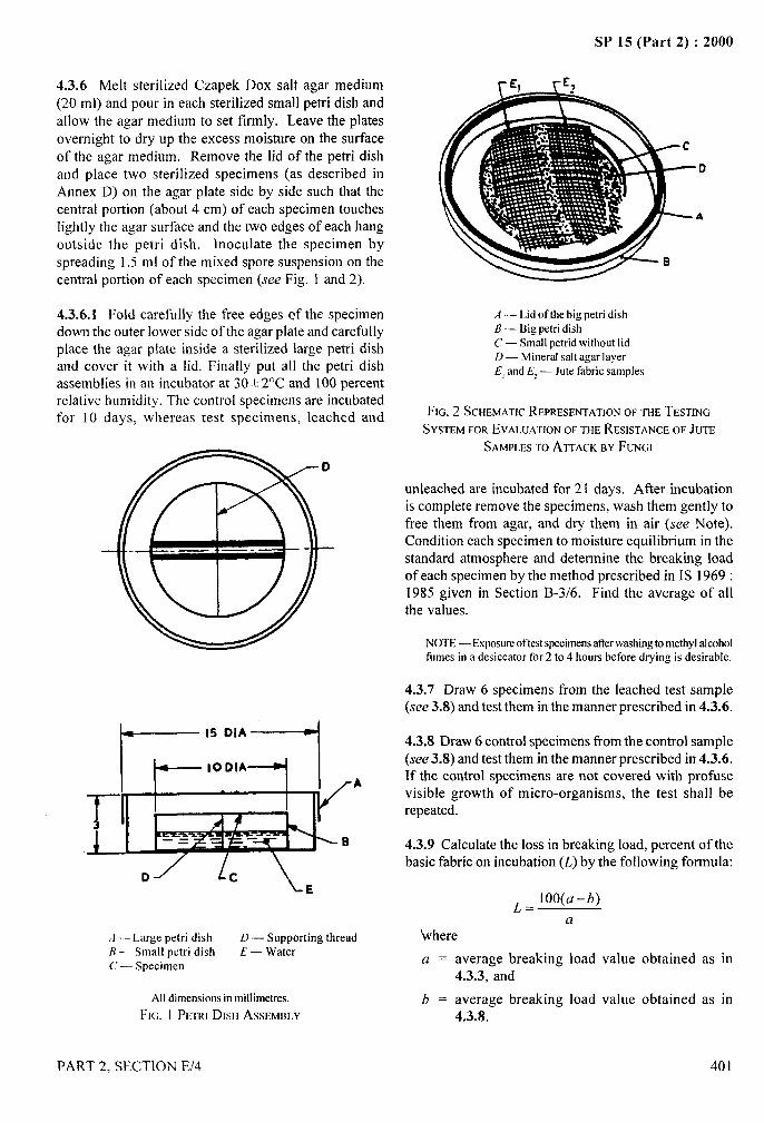
SP 15 (Part 2) :2000
4.3.6 Melt sterilized Czapek Dox salt agar medium(20 ml) and pour in each sterilized small petri dish and
allow the agar medium to set firmly. Leave the platesovernight to dry up the excess moisture on the surfaceof the agar medium. Remove the lid of the petri dish
and place two sterilized specimens (as described inAnnex D) on the agar plate side by side such that thecentral portion (about 4 cm) of each specimen toucheslightly the agar surface and the two edges of each hang
outside the petri dish. inoculate the specimen byspreading 1.5 ml of the mixed spore suspension on thecentral portion of each specimen (see Fig. 1 and 2).
4.3.6.1 Fold carefully the free edges cf the specimen ,4— Lid of the big petri dish
down the outer lower side of the ag~r plate and carefullyplace the agar plate inside a sterilized large petri dishand cover it with a lid. Finally put all the petri dishassemblies in an incubator at 30+ 2°C and 100 percent
B — Big petri dishC — Small petrid without lidD — Mineral salt agar layerEl and El — Jute fabric samples
relative humidity. The control specimens are in&batedfor 10 days, whereas test specimens, leached and FIG. 2 SCHEMATIC REPRESENTATION OF THE TESTING
SYSTEM FOREVALUATIONOFTHERESISTANCEOF JUTE
.
“--l,,‘h
SAMPLESTOATTACKEIYFUNGI
unleached are incubated for 21 days. After incubationis complete remove the specimens, wash them gently tofree them from agar, and dry them in air (see Note).Condition each specimen to moisture equilibrium in thestandard atmosphere and determine the breaking loadof each specimen by the method prescribed in 1S 1969:1985 given in Section B-3/6. Find the average of allthe values.
NOTE— Exposureoftest specimensatterwashingto methylalcoholfumes in a desiccator for 2 to 4 hours before drying is desirable. \
4.3.7 Draw 6 specimens from the leached test sample(see 3.8) and test them in the manner prescribed in 4.3.6.
4.3.8 Draw 6 control specimens from the control sample(see 3.8) and test them in the manner prescribed in 4.3.6.If the control specimens are not covered with profusevisible growth of micro-organisms, the test shall berepeated.
J 4.3.9 Calculate the loss in breaking load, percent of thebasic fabric on incubation (L) by the following formula:
D
:,
~= Ioo(a-b)
a
A — Large petri dish D — Supporting thread ‘whereB— Small petri dish E — WaterC — Specimen a = average breaking load value obtained as in
4.3.3, and
All dimensionsin millimetres. b = average breaking load value obtained as in ,
FIG. I P~TRI DISH AssmmI,Y 4.3.8.
PART 2, SECTION E/4 401
SP 15 (Part 2) :2000
.,*d.——
If the value of L is less than 70 percent, the test shall berepeated.
4.3.10 Calculate in the manner prescribed in 4.3.9 theloss in breaking load, percent, of the fabric under teston incubation prior to leaching, equating to:
‘a’ the value obtained as in 4.3.1, and‘b’ the value obtained as in 4.3.6.
NOTE — The fabric should be considered satisfactorily resistantto attack by micro-organisms if the value of L does not exceed20 percent. ‘
4.3.11 Calculate in the manner prescribed in 4.3.9 theloss in breaking load, percent, of the fabric under test onincubation after leaching, equating to:
‘a’ the value obtained as in 4.3.2, and‘b’ the value obtained as in 4.3.7.
NOTE — The fabric should be considered satisfactory resistantto attack by micro-organisms if the value of L does not exceed20 percent.
5 SOIL BURIAL METHOD
the soil. The soil inside the jars should cover about three-fourth of their height and the specimens should be about5 cm to 6 cm below the soil surface. Cover the jars withpetri dishes and keep them in the incubator at 30 + 2°C.Incubate the specimens for 21 days. After21 days ofincubation, check the moisture of the soil and, if needbe, adjust the moisture to 25 to 27 percent. Remove thespecimens, wash them gently to free them from soil,and dry them in air (see Note). Condition the specimensto moisture equilibrium in the standard atmosphere anddetermine the breaking load of each specimen by themethod prescribed in IS 1969 : 1985 given in SectionB-3/6. Find the average of all the values.
NOTE — Exposure of the test specimen after washing to methylalcohol fumes in a desiccator for 2 to 4 hours before drying givenbetter results.
5.3.3 Take the remaining 6 leached test specimens(see 3.8) and test them in the manner prescribed in 5.3.2.
5.3.4 Take the remaining 6 control test specimens(see 3.8) and test them in the manner prescribed in 5.3.2.
5.3.5 Calculate the loss in breaking load, percent, ofthe basic fabric on soil burial (L) by the followingformula:
5.1 Apparatus ~=loo (a-b)
a5.1.1 Glass Jars where
a = average breaking load value obtained as in
Round, wide-mounted, flat-bottomed. 4.3.3, andb = average breaking load value obtained as in
5.1.2 Petri Dishes 4.3.4.If the value of L is less than 80 percent, the test shall be
As covers. repeated.
5.1.3 Incubator 5.3.6 Calculate in the manner prescribed in 5.3.5 theloss in breaking load, percent, of the fabric under test on
Capable of being maintained at 30 * 2°C and provided soil burial prior to leaching, equating to:
with trays full 6f water at the bottom.‘a’ the value obtained as in 4.3.1, and
5.2 Test Soil‘b’ the value obtained as in 5.3.2.
Prepared as prescribed in Annex C.NOTE —The fdxic shouldbe consideredsatisfactorilyresistanttoattack by micro-organisms if the value of L does not exceed20 percent.
5.3 Procedure ‘$5.3.7 Calculate in the manner prescribed in 5.3.5 the
5.3.1 Take the remaining 6 test specimens (see 3.8).loss in breaking load, percent, of the fabric under test onsoil burial after leaching, equating to:
5.3.2 Spread the test soil on each specimen in a thinlayer and roll it lightly into the form of a cylinder. Place ‘a’ the value obtained as in 4.3.2, and
each specimen separately in a glass jar of suitable size ‘b’ the value obtained as in 5.3.3.
containing a thin layer of soil at the bottom, and pour NOTE —The fabricshouldbe consideredsatisfactorilyresistanttosoil in the jar to cover the sides and top of the specimen, attack by micro-organisms if the value of L does not exceedthus bringing both sides of the specimen in contract with 20 percent.
402 PART 2, SECTION E/4
“1t’
I\,i
II
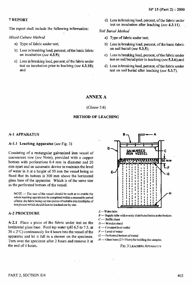
4—-
SP 15 (Part 2) :2000
7 REPORT
The report shall include the following information:\
Mixed Culture Method
a)
b)
c)
Type of fabric under test;
Loss in breaking load, percent, of the basic fabricon incubation (see 4.3.9);
Loss in breaking load, percent, of the fabric undertest on incubation prior to leaching (see 4.3.10);and
A-1 APPARATUS
d) Loss in breaking load, percent, of the fabric under –-*
test on incubation after leaching (see 4.3.11).[
ANNEX A
(Clause 3.6)
METHOD OF LEACHING
A-2 PROCEDURE
Soil Burial Method
a) Type of fabric under test;
b)
c)
Loss in breaking load, percent, of the basic fabric.,
on soil burial (see 5.3.5);
Loss in breaking load, percent, of the fabric undertest on soil burial prior to leaching (see 5.3.6);and
Loss in breaking load, percent, of the fabric undertest on soil burial after leaching (see 5.3.7).
A-1.l Leaching Apparatus (see Fig. 3)
Consisting of a rectangular galvanized iron vessel ofconvenient size (see Note), provided with a copperbottom with perforations 0.4 mm in diameter and 20mm apart and an automatic device to maintain the levelof water in it at a height of 50 mm the vessel being sofixed that its bottom is 300 mm above the horizontalglass base of the apparatus. Which is of the same sizeas the perforated bottom of the vessel.
NOTE — The size of the vessel should be such as to enable thewhole leachingoperationto be completedwithkra reasonableperiodoftime, the fabricbeing cut into pieces of suitablesize (multiplesoftest pieces)which shouldthen be leachedone by one.
61 r—-’0>
-------- ----
I
A—Water inletB — Supply tube with evenly distributed holes at the bottomC — Btie sheet
A-2.1 Place a piece of the fabric under test on the D— Wooden standhorizontal glass base. Feed tap water @H 6.5 to 7:5, at E— Constantlevel outlet
30+ 2“C) continuously for 4 hours into the vessel of the ~— J-evelof water
apparatus and let it fall in a shower on the specimen. G — Pertormed bottom of vessel
Turn over the specimen after 2 hours and remove it at H— Glass base (27X55cm)for holding the samples
the end of 4 hours. FIG. 3 LEACHINGAPPARATUS
\,)”:
PART 2, SECTION E/4
/
403
...—SP 15 (Part 2) :2000
ANNEX B
(Clause 4.3.4)
PREPARATION OF CZAPEK DOX SALT AGAR MEDIUM AND MIXED SPORE SUSPENSION
B-1 PREPARATION OF CZAPEK DOX SALTAGAR MEDIUM
B-1.l Dissolve the following salts in Quantitiesindicated per 100 ml of distilled water.
Solution A
Sodium nitrate (NaNOJ 0.8 g
Magnesium sulphate 0.2 g
(MgSO,.7H,0)Potassium chloride (KCI) 0.2 g
Solution B
Potassium dihydrogen phosphate 0.1 g
(KH,POJDipotassium hydrogen phosphate 0.3 g
(K, HPO,)
During preparation of the medium, mix solution A andB in the proportion 1:1. Add equal volume of distilledwater. Finally add agar (2 percent vz/v). Heat on a waterbath to dissolve agar and dispense in culture tubes in20 ml quantities each. Plug the culture tubes with non-
absorbent cotton and sterilize the medium in an autoclaveat 103.35 kPa (15 psi) for 15 min.
B-2 PREPARATION OF MIX SPORE SUSPENSION
B-2.1 Media and Salt Solution
B-2.1.1 Czupek Dox Agar Slants
Prepare Czapek Dox-agar medium as described in B-1.Dispense 7 ml of this medium in culture tubes, plug
and sterilize at 103.35 kpa (15 psi) for 15 min. In aseparate culture tube, sterilize several filter paper strips(1 cm x 6 cm) in a similar way. Following sterilization,
place the culture tubes containing hot, molten medium
in a slanting position until the agar solidifies. Nextintroduce filter paper strips on the surface of agar slantsaseptically, one filter paper per agar slant.
B-2. 1.2 Malt Extract-Peptone Agar Slants
Dissolve 2.5 g of malt extract and 0.1 g of peptone in100 ml distilled water. Adjust pH to 6.0. Add agar(2 percent n7/v) and dissolve it by heating over a water
404
.-.
bath. Dispense in culture tubes, 7 ml quantities pertube, plug with non-absorbent cotton and sterilize at103.35 kPa(15 psi) for 15 min. Following this, preparemalt agar slants by keeping the culture tubes containinghot, molten malt agar in a slanting position, until the
agar solidifies.
B-2.1.3 Quadruple strength Czapek Dox salt solutionwith 0.01 percent triton:
Dissolve the following salts in quantities indicated per100 ml of distilled water.
Solution A
Sodium nitrate (NaNOJ 1.6g
Magnesium sulphate 0.4 g
(MgSO,.7H,0)Potassium chloride (KC1) 0.4 g
Solution B
Potassium dihydrogen phosphate 0.2 g
(KH,PO,)Dipotassium hydrogen phosphate 0.6 g
(K,HPO,) .(
Sterilize each solution separately. After auto-claving atI
103.35 kPa (15 psi) for 15 rein, mix the two solutions \\;..
when cold and add sterilized triton water so that the!\).,
final concentration of triton in the solution becomes 0.01percent (v/v).
B-2.2 Maintenance of Cultures
B-2.2.1 The following fungal strains shall be preservedin Czapek Dox filter paper agar slants:
a)b)c)d)
Chaetomium indicum
Curvularia Lunata
Aspergillus fumigatus :,Pencillium rubrum
B-2.2.2 Penicillium wortmanni, however, shall bepreserved malt extract peptone agar-slants.
B-2.3 Sub-cultures
B-2.3.1 Inoculate malt extract-peptone agar slantsseparately with well sporulated cultures of the above
PART 2, SECTION E/4
,4.—.. ... —
SP 15 (Part 2) :2000
mentioned five organisms. Incubate the tubes at30+ 2°C for 7 to 10 days until mature growth of theorganisms is obtained. Equal number of sub-culturesshall be made for each fungal culture.
B-2.4 Preparation of Mixed Spore Suspension
B-2.4. 1 Take equal number of malt agar slant culturesof each of the 5 micro-organisms mentioned above. Add
5 ml quadruple strength Czapek Dox salt solution
supplemented with 0.01 percent triton to each cukure–q
tube. Lightly scratch the surface of growth aseptically tby a sterilized glass rod and rotate the culture tubesbetween the palms until the spore suspension in the tube
1
. .---- :
is moderately dense. Filter the spore suspension through:,
a piece of sterile muslin or suspension through a pieceof sterile muslin or cotton-wool in a sterilizedErlenmeyer flask. In a similar way, pool sporesuspensions from all the slant cultures in the sameErlenmeyer flask. Mix the spores well by placing theflask on a cyclomixer.
ANNEX C
(Clause 5.2)
PREPARATION OF TEST SOIL
C-1 Prepare a compost by mixing thoroughly fertilegarden soil, cowdung manure and sand in the proportionof 2:1 :1. Pass it through 355pm IS Sieve [see IS 460(Partl) :1978 ]. Adjust its moisture content to 25 to 27percent and test it in the manner prescribed in C-1.lto C-1.5.
C-1.l Take a sufficiently long piece of hessian of thefollowing construction and draw from it 12 pieces, eachof size 25 cm x 4 cm:
Ends/cm 4
Picks/cm 4
Mass, g/m2 270
C-1.2 Take 6 pieces of the hessian, condition themto moisture equilibrium in the standard atmosphere(see 2) and determine the breaking load of each by themethod prescribed in IS 1969 : 1985 given in B-3/6.Find the average of all the values.
C-1.3 Test the remaining 6 pieces of the hessian in themanner prescribed in 5.3.2, incubating the pieces for 7days only. Record the average value for breaking load.
C-1.4 Calculate the loss in breaking load, percent, ofthe cloth after soil burial.
C-1.5 The soil shall be deemed to be suitable for thetest if the loss in breaking load of the cloth, so determinedis 80 percent or more.
ANNEX D
(Clause 4.3.6)
STERILIZATION OF JUTE SPECIMENS IN METHYL ALCOHOL VAPOUR
D-1 PROCEDURE desiccator to the second desiccator with a pair of sterile
tongs in a sterile chamber/environment. Connect the
D-1. 1 Pack the specimens loosely in a desiccator of second desiccator to a vacuum pump through a cotton-
suitable size containing methyl alcohol and keep them wool filter and exhaust the desiccator at room
for 24 hours (or longer) at room temperature. In the temperature for 6 hour to remove traces of methyl
meantime, make another desiccator ready by sterilizing alcohol. Bring the pressure in the desiccator to the
it with methyl alcohol vapour for a period of 12 hours at atmospheric pressure
room temperature. Transfer the specimens from the first the cotton-wool filter.
PART 2, SECTION E/4
by slowly letting in air through
405
\,\,,
/
... ,.4<
— “—
..—
SP 15 (Part 2) :2000
METHOD FOR TESTING FLAX FABRICS FORRESISTANCE TO ATTACK BY MICRO-ORGANISMS
(Source : IS 3856: 1966)
The flax fabrics are mainly used for making hoses used by fire services for pumping water for extinguishing fireoutbreaks. Like cotton, flax is also liable to deterioration by the action of micro-organisms. Since fwe hoses areoften stored, transported and used under conditions favorable for growth of micro-organisms, protective treatmentsare applied.
Studies on the pattern of microbial degradation of flax fabrics in soil have revealed the predominant activity of thetwo fingi, namely, Pencilliumjimiculosm and Memnoniella echinata. These two fimgi cause more than 90 percentloss in the breaking strength when used in ‘pure culture’ test in 42 days. Whilst in soil enriched with these timgi,flax fabrics register 100 percent loss in breaking strength in 28 days.
Two quantitative methods, namely, ‘soil burial’ method and ‘mixed culture’ method, have been prescribed in thistest method. The soil burial method is intended for testing rotproofhess of the treatment, involving burial incomposted soil enriched with the two specific fimgi; while the mixed culture method determines the resistance ofthe flax fabric to fimgal attack by infecting the fabric with Penicillium jimiculosm and Memnoniella echinata.
These methods may also be used for evaluating preservatives or treatments designed to protect flax fabrics fromdamage due to micro-organisms.
Cultures of the organisms prescribed in this standard for this test may be obtained from the Director, DefenceResearch Laboratory (Materials), P.B. N0.320, kanpur, To facilitate supply, the culture numbers as referred belowmay also be mentioned:
Micro-organism
A4emnoniella echinata
Penicillium funiculosm
1 SCOPE
It prescribes methods for evaluating flaxresistance to attack by micro-organisms.
2 SAMPLING
2.1 Lot
The quantity of flax fabrics of the same typedelivered to a buyer against a despatchconstitute a lot.
D.R.L. (M) Culture No.
fabrics for
and qualitynote shall
2.2 Unless otherwise agreed to between the buyer andthe seller the number of pieces to be selected at randomfrom a lot shall be as given below:
Lot Size Sample Size
up to 150 3
151 to300 4
301 to 500 5
501 and above 7
406
843844
2.3 The pieces thus selected shall constitute the test
sample.
2.4 From the basic fabric, take sufficiently long piece.The piece thus taken shall constitute the controlsample.
3 SOIL BURIAL METHOD
3.1 Test Soil
For the purpose of this method, prepare test soil in themanner prescribed in Annex A.
3.2 Spore Suspension
3.2.1 Prepare the spore suspension of the followingorganisms in the manner prescribed in Annex B;
a) Memnoniella echinata, and
b) Penicillium jimiculosm..
PART 2. SECTION E/5
.—4-1
.

. 4.
SP 15 (Part 2) :2000
3.3 Procedure B-3/6). Find the average of all the test values.
I
3.3.1 From each piece in the test sample, cut out, atrandom, at least 3 test specimens so that the total numberof test specimens obtained is at least 15. Each testspecimen shall be 325 mm x 60 mm in size with thelonger side parallel to warp threads. Mark these testspecimens suitably for identification. The test specimensthus obtained shall be divided into 3 equal groups eachcontaining at least one test specimen ti-om each piece.
3.3.2 Take the test specimens belonging to the fwst groupand determine the breaking load of each test specimenby the method prescribed in 9.1 of IS 1969:1968‘Method for determination of breaking load andelongation at break of woven fabric (by constant-rate-or-traverse machine)’. (see Section B-3/6). Find theaverage of all the test values.
NOTE —The size of the test strip should be 200 mm x 50 mm.
3.3.3 Put the test soil in different 1-Iitre glass jars
(17 cm in height and 6 cm in diameter) having metallicscrew caps. Spray 5 ml of the mixture of two sporesuspensions on the test soil (see Note). Bury one testspecimen belonging to the second group in each jar insuch a way that the test specimen takes up ‘U’ shapeinside the soil with two free ends (each 5 cm) projectingabove the soil surface. Incubate the specimens at30+ 2°C and 98+2 percent relative humidity for 28days. At the end of this period, remove the specimen,wash free from soil, dry them in air and determine thebreaking load of each specimen by the method prescribedin 9.1 of IS 1969: 1968 ‘Method for determination ofbreaking load and elongation at break of woven fabric(by constant-rate-or traverse machine)’ (see sectionB-3/6). Find the average of all the test values.
NOTE — While preparing soil compost the mixtureof suspensionis added to the soil and moistened adequately to have specifiedmoisturecontent,
3.3.4 Leach the test specimens belonging to the thirdgroup in the manner prescribed in Annex C and testthem in the manner prescribed in 3.3.3.
3.3.5 From the control sample cut at random 10 testspecimens each measuring 325 mm x 60 mm with theirlonger sides parallel to warp threads. Take fivespecimens and determine the breaking load of eachindividual specimen by the method prescribed in 9.1 ofIS 1969:1968 ‘Method for determination of breakingload and elongation at break of woven fabric
(by constant-rate-or-traverse machine)’ (see Section
3.3.6 Test the remaining five specimens in the mannerprescribed in 3.3.3.
3.3.7 Calculate the loss in breaking load, percent, of thebasic fabric, on soil burial, by the following formula:
~= 100 (a–~)
awhere
L.
a=
b=
Loss in breaking load, percent, of the basicfabric on soil burial,
Average breaking load value obtained as in3.3.5, and
Average breaking load value obtained as in
3.3.6.
NOTE — The vahreof~ shouldbe 90 percentor more. If thk vahreis less than 90 percent, the test should be repeated.
3.3.8 Calculate in the manner prescribed in 3.3.7, theloss in breaking load, percent, of the fabric under test onsoil burial without prior leaching but equating to:
‘a’ value obtained as in 3.3.2, and‘b’ value obtained as in 3.3.3.
NOTE — The value ofL should not be more than 10percent. Thefabricshouldbeconsideredsatisfactorilyresistantto attackby micro- .-organismsif the value of L does not exceed 10percent.
3.3.9 Calculate in the manner prescribed in 3.3.7 the ~,:loss in breaking load, percent, of the fabric under test onsoil burial after leaching but equating to:
‘a’ value obtained as in 3.3.2, and‘b’ value obtained as in 3.3.4.
NOTE — The value of L should not be more than 10 percent.The fabric should be considered satisfactorily resistant toattack by micro-organisms if the value of L does not exceed10 percent.
3.4 Report the results of the test as under:
a)
b)
c)
Loss in breaking load, percent of the basic fabricon soil burial (see 3.3.7);
Loss in breaking load, percent of the fabricunder test on soil burial without prior leaching(see 3.3.8); and
Loss in breaking load, percent of the fabric under I
test on soil burial after leaching (see 3.3.9).
PART 2, SECTION E/5 407
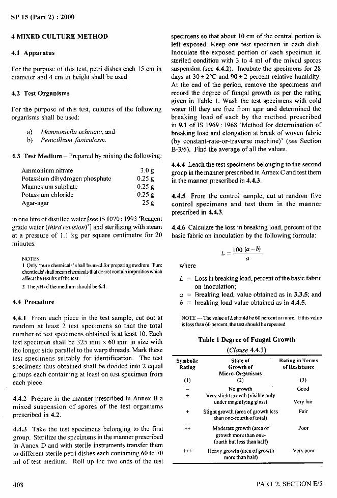
SP 15 (Part 2) :2000
4 MIXED CULTURE METHOD
4.1 Apparatus
For the purpose of this test, petri dishes each 15 cm indiameter and 4 cm in height shall be used.
4.2 Test Organisms
For the purpose of this test, cultares of the followingorganisms shall be used:
a) Memnoniella echinata, andb) Penicillium funiculosm.
4.3 Test Medium – Prepared by mixing the following:
Ammonium nitrate 3.0 g
Potassium dihydrogen phosphate 0.25 g
Magnesium sulphate 0.25 g
Potassium chloride 0.25 g
Agar-agar 25 g
in one litre of distilled water [see IS 1070:1993 ‘Reagentgrade water (third revision)’] and sterilizing with steam
at a pressure of 1.1 kg per square centimetre for 20minutes.
NOTES1 Only ‘purechemicals’ shall be used for preparingmedium. ‘Purechemicals’shallmeanchemicalsthat donotcontainimpuritieswhichaffect the results of the test.
2 ThepH of the medium should be 6.4.
4.4 Procedure
4.4.1 From each piece in the test sample, cut out atrandom at least 2 test specimens so that the totalnumber of test specimens obtained is at least 10. Eachtest specimen shall be 325 mm x 60 mm in size withthe longer side parallel to the warp threads. Mark thesetest specimens suitably for identification. The testspecimens thus obtained shall be divided into 2 equalgroups each containing at least on test specimen from
each piece.
4.4.2 Prepare in the manner prescribed in Annex B amixed suspension of spores of the test organismsprescribed in 4.2.
specimens so that about 10 cm of the central portion isleft exposed. Keep one test specimen in each dish.Inoculate the exposed portion of each specimen insteriled condition with 3 to 4 ml of the mixed sporessuspension (see 4.4.2). Incubate the specimens for 28days at 30+ 2°C and 90+2 percent relative humidity.At the end of the period, remove the specimens andrecord the degree of fimgal growth as per the ratinggiven in Table 1. Wash the test specimens with coldwater till they are free from agar and determined thebreaking load of each by the method prescribedin 9.1 of IS 1969: 1968 ‘Method for determination ofbreaking load and elongation at break of woven fabric(by constant-rate-or-traverse machine)’ (see SectionB-3/6). Find the average of all the values.
4.4.4 Leach the test specimens belonging to the secondgroup in the manner prescribed in Annex C and test themin the manner prescribed in 4.4.3.
4.4.5 From the control sample, cut at random five
control specimens and test them in the mannerprescribed in 4.4.3.
4.4.6 Calculate the loss in breaking load, percent of the
basic fabric on inoculation by the following formula:
~=loo(a–@
awhere
L = Loss in breaking load, percent of the basic fabricon inoculation;
a = Breaking load, value obtained as in 3.3.5; andb = breaking load value obtained as in 4.4.5.
NOTE — The valueofL shouldbe 60 percentor more. Ifthis valueis less than 60 percent, the test should be repeated.
Table 1 Degree of Fungal Growth
(Clause 4.4.3)
Symbolic State of Rating in TermsRating Growth of of Resistance
Miero-Organisms,(1) (2) (3)
— No growth Good* Very slight growth (visible only
under magnifying glass) Very fair
+ Slight growth (area of growth less Fairthan one-fourth of total)
4.4.3 Take the test specimens belonging to the first ++ Moderate growth (area of Poor
group. Sterilize the specimens in the manner prescribed growth more than one-
in Annex D and with sterile instruments transfer themfourth but less than half)
to different sterile petri dishes each containing 60 to 70 +++ Heavy growth (area of growth Very poor
ml of test medium. Roll up the two ends of the testmore than half)
1k...--- !:,’
7 $>,!
I.1
408 PART 2, SECTION E/5
IIi’~I
,4. ---- .. .
SP 15 (Part 2) :2000
4.4.7 Calculate in the manner prescribed in 4.4,6 theloss in breaking load, percent, of the fabric under test,on inoculation without prior leaching but equating to:
‘a’ the value obtained as in 3.3.2; and‘b’ the value obtained as in 4.4.3.
NOTE— The value of L should not be more than 10percent. Thefabricshouldhe consideredsatisfiwtnrilyresistaotto attackby micro-organisms if the vrdueof L does not exeeed 10percent.
4.4.8 Calculate in the manner prescribed in 4.4.6 theloss in breaking load, percent, of the fabric under test,on inoculation after leaching but equating to:
‘a’, the value obtained as in 3.3.2; and‘b’, the value obtained as in 4.4.4.
NOTE — The value of L should not be more than 10percent. Thefabricshouldbe consideredsatisfactorilyresistantto attackby micro-organisms if the vrdueof L does not exeeed 10percent.
4.5 Report the results of the test as under:
a) Loss in breaking load, percent, of the basicfabric on inoculation (see 4.4.6),
b) Loss in breaking load, percent, of the fabricunder test on inoculation without prior leaching(see 4.4.7), and
c) Loss in breaking load, percent of the fabricunder test on inoculation after leaching(see 4.4.8).
ANNEX A
(Clause 3.1)
PREPARATION OF TEST SOIL
A-1 PROCEDURE
A-1.l Mix thoroughly:
a) a layer of good, sandy loam soil, 13 cm thick;b) a layer of fi-eshcow-dung manure 7.5 cm thick andc) a layer of finely chopped straw 15 cm thick.
Allow the mixture to ferment for 2 months turning itonce a weak, maintaining the moisture content at 22 to25 percent on the total weight of the mixture. At theend of the period, sift the resulting compost through3.35-mm IS Sieve (see IS 460:1962 ‘Specification fortest sieves’) and test it in the manner prescribed below.
A-1.l.l Take a light-weight cotton fabric weighing 240to 255 g per square metre. Draw six 325 mm x 60 mm
pieces from it. Take three pieces and determine the
breaking load of each individual piece by the methodprescribed in 9.1 of IS 1969:1961 given in SectionB-3/6. Find the average of all the values.
A-1.1.2 Bury the remaining three pieces in the compost(see A-1.1) for 5 days. At the end of the period, removethe pieces from the compost and determine the breakingload of each individual piece by the method prescribedin 9.1 of IS 1969:1961 given in Section B-3/6. Findthe average of all the values.
A-1.2 Calculate the loss in strength of the fabric aftersoil burial.
NOTE — The soil should be deemed to be suitable for test if theloss in strengthof fabric so determined is 80 pereent or more.
‘1;..--~
\
PART 2, SECTION E/5 409
. ----SP 15 (Part 2) :2000
ANNEX B
(Clauses 3.2.1 and 4.4.2)
PREPARATION OF SPORE SUSPENSION
B-O GENERAL
B-O.1 [f a mixed suspension of spores of more than onetest organism is to be prepared, the suspensions of sporesof each test organism shall be prepared separately andthe suspensions then mixed in equal volumes.
B-1 PREPARATION OF CULTURE MEDIUM
B-1.1 Take sufficient quantity of potatoes, say, about250 g, peel them off and cut them into slices. Weigh200 g of the sliced potatoes, wash them in running tapwater and place them in a beaker; add 500 ml of distilledwater and keep the contents at boil for 30 minutes. Filterthe hot extract through a thin ~ayer of absorbent cotton
previously wetted with distilled water. Preserve thefiltrate.
B-1.2 Take 25 g of agar, cut it into small pieces and
boil, in the minimum quantity of distilled waternecessary till no solid agar is visible. Add 20 g ofdextrose and mix it with the filtrate (see B-1.1). Makeup the volume to 1 000 ml with hot distilled water.Adjust the pH of the culture medium to 6.4.
NOTE — To avoid solidification, the temperature of the culturemedium should be kept above 45”C.
B-1.3 Put 5 ml of the culture medium into each of anumber of 15 cm x 2 cm test-tubes and plug them with
non-absorbent cotton-wool.
the culture medium with1.1 kg/cm2 for 20 minutes.remove the test-tubes from the autoclave, place them ina slanting position and allow them to cool to harden the
culture medium into ‘slants’.
B-2 PREPARATION OF SUB-CULTURE
B-2. 1 Inoculate the slants in the test-tubes with a well-sporulated culture of test organism (see 3.2.1) by meansof a sterile needle. Incubate the slants for 7 days at30+2°C.
NOTE — At the end of this period, a heavy growth of the freshlysporulatingtest organismshould be visible within the tubes.
B-3 PREPARATION OF SPORE SUSPENSION
B-3.1 Add about 10 ml of sterile distilled water tofreshly sporulating subculture of the test organism(see B-2) within the tubes. Bring the spores of thesub-culture into suspension by shaking or disturbing
them gently with a sterile glass rod. Filter thesuspension through a sterile muslin or similar fabricto remove particles of agar or fungal mycelium.Examine a drop of the spore suspension under a low
power microscope, and see whether 50 or more sporesappear in the field.
In an autoclave, sterilizesteam at a pressure ofAt the end of the period,
I
410 PART 2, SECTION E/5
#,_.!”_
SP 15 (Part 2) :2000
ANNEX C
(Clauses 3.3.4 and 4.4.4)
METHOD OF LEACHING
C-1 PROCEDURE pH of not less than 6.0 and not more than 8.0 and
C-1.1 Place the specimen inside a glass jar with internaltemperature of 30 + 2°C) to flow into it at the rate of 10litres per hour.
diameter of 9 cm. Through a capillary, extending toIn this stream of water, leach the
specimen for 24 hours.within 0.6 cm of the bottom of the jar, allow water (with
ANNEX D
(Clause 4.4.3)
STERILIZATION IN METHYL ALCOHOL VAPOUR
D-1 PROCEDURE
D-1.l Pack the specimens loosely in a desiccator ofsuitable size containing methyl alcohol and keep themfor 24 hours (or longer) at room temperature (about27”C). In the meantime, make another desiccator ready
by sterilizing it with methyl alcohol vapour for a periodof 12 hours at room temperature. Transfer the
.-.
specimens from the first desiccator to the seconddesiccator with a pair of sterile tongs. Connect thesecond desiccator with a water pump through a cotton-WOO1 filter and exhaust the desiccator at roomtemperature for 6 hours to remove traces of methylalcohol. Bring the pressure in the desiccator to theatmospheric pressure by slowly letting in air through
the cotton-wool filter.
f,,-
)
/
PART 2, SECTION E/5 411
II
~:
I
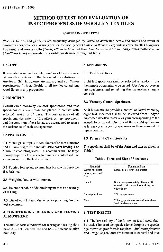
SP 15 (Part 2) :2000
“., ,
. &<
.—-—
METHOD OF TEST FOR EVALUATION OFINSECTPROOFNESS OF WOOLLEN TEXTILES
(Source : IS 7250: 1995)
Woollen fabrics and gamlents are frequently damaged by larvae of dermested beetle and moths and result inenormous economic loss. Among beetles, the woolly bear (Arrthrenusfiavipes Lee) and the carpet beetle (AttagerwsJasciatus); and among moths (Tineapellionella Linn and Tinea translucent) and the webbing clothes moth (Tineola
bisselliella Hum) are mainly responsible for damage throughout India.
1 SCOPE
It prescribes a method for determination of the resistance
of woollen textiles to the larvae ofl (a) Anthrenus
f7avipes, (b) Attagenus fasciatus, and (c) Tinea
translucent. It is applicable to all textiles containingwool tibres in any proportion.
2 PRINCIPLE
Conditioned voracity control specimens and testspecimens of known mass are placed in contact with
selected larvae for 14 days. The loss in mass of allspecimens, the extent of the attack on test specimens
and the condition of test larvae are ascertained to assessthe resistance of each test specimen.
3 APPARATUS
3.1 Metal, glass or plastic containers of 45 mm diameterand 10 mm height with metal/plastic cover having 4 or5 minute ventilating holes. This container shall be largeenough to permit test larvae to remain in contact with, ormove away from the test specimen.
3.2 Pointed forcep and a camel hairbrush with pesticidefree bristles.
3.3 Weighing bottles with stopper.
3.4 Balance capable of determining mass to an accuracyof O.1 mg.
3.5 Die of 40 + 1.5 mm diameter for punching circulartest specimen.
4 CONDITIONING, REARING AND TESTINGATMOSPHERE
The atmospheric conditions for rearing and testing shallhave 27+ 1“C temperature and 65*2 percent relativehumidity.
412
5 SPECIMENS
5.1 Test Specimens
Eight test specimens shall be selected at random fromthe sample of material to be tested. Use four of these astest specimens and remaining four as moisture regaincontrols.
5.2 Voracity Control Specimens
As it is essential to provide a control on larval voracity,eight test specimens shall be selected from undyedunproofed woollen material or yam corresponding to thesample to be tested. Use four of these eight specimensas larvae voracity control specimen and four as moistureregain controls.
5.3 Form and Characteristics
The specimen shall be of the form and size as given inTable 1.
Table 1 Form and Size of Specimens
Material Form and SizeWovenorKnhted Discs, 40+ 1.5mm in diameterfabrics, felts andfurs
Carpet Squares approximately 30 mm x 30mm with tuft and/or loops along theedges intact
Carpet pile alone 200 mg specimens
Yarn 200 mg specimens, wound into a loosehank in the container
6 TEST INSECTS
6.1 The larva of any of the following test insects shallbe used. Choice of test species depends upon the speciesagainst which proofhess is required. Anthrenus~avipes
and Attagenus fasciatus are difficult to control and thus
PART 2, SECTION E/6

4.——
SP 15 (Part 2) :2000
,,)
require high level of insectproofing agent than Tines
translucent:
a) Anthrenus ,jlavipes 10-11 weeks old
b) Attagenus fasciatus 11-12 weeks old
c) Tines translucent 24-27 days old
6.2 Details of breeding of the above larvae are given in
Annex A. In case, there is any deviation in rearing
medium or temperature and relative humidity, h may call
for some deviation in the age of the larvae used for tests.
In that case the deviation shall be indicated in the test
report. Differences caused by variation in temperature
and humidity are largely overcome by use of standard
conditions given in 4.
7 PROCEDURE
7.1 Condition all the sixteen specimens in the
atmosphere specified in 4 for 24 hours. Then determine
the mass of each specimen separately in a stoppered
weighing bottle to an accuracy of 0.1 mg.
7.2 Place each of the test and voracity control specimens
of known mass in a separate container. On to each ofthe four test specimens and the four voracity controlspecimens place fifteen larvae of the selected insect orpest (These larvae should be subjected to fasting for 24h before their release on specimens).
7.3 Keep the sixteen containers in the dark in the testatmosphere for a period of 14 days.
7.4 After test period, remove all larvae, cast skins(exuviae) excrements and loose tlbres from the test
specimens and voracity control specimens by means ofpointed forceps and a camel hair brush.
7.5 Count and record for each test specimen the numberof surviving, dead or pupating larvae.
7.6 Transfer the test specimen, the voracity control
specimens and moisture regain control specimens tosmall tared weighing bottles. Determine the massseparately of the test, voracity control and moistureregain control specimens.
7.7 Test is invalid if the mean loss in mass of the fourvoracity controls is less than 35 mg, or any single valueis less than 25 mg or more than 25 percent of the controllarvae die or pupate.
8 OBSERVATIONS AND CALCULATIONS 2
3
8.1 Method of Calculation aud Formula.. .----J
8.1.1 Determine the loss in mass (m) of each test 1‘$‘1
specimen and voracity control specimen due to insectfeeding as follows :
mOx m,m.
mz ‘ml
where
mO=
m.
m.2
m.3
mass of the test specimen or voracity controlspecimen before exposure to larvae,
mass of the test specimen or voracity controlspecimen after exposure to larvae for 14 days,
mean initial mass of appropriate moistureregain controls, and
mean final mass of appropriate moisture regaincontrols.
8.2 Visual Assessment of Insectproofness
8.2.1 Examine each test specimen and assess the visibledamage using the symbols given in Tables 2 and 3.
Table 2 Estimation of Cropping
Symbol Cropping: Visible Surface Damage
I No detectabledamage
2 Very slight cropping
3 Moderate cropping ~
4 Veryheavycropping
Table 3 Estimation of Holes
Symbol Estimation of Holes
A No detectabledamage
B Yarn or tibres ptiially severed
c A few small boles. yam or tibres severed
D Several large holes
8.3 Visual Assessment of Larval Condition
Count and record for each test specimen the number oflarvae in each of the following conditions:
a) Live,
b) Dead, and Ic) Pupating.
PART 2. SECTION E/6 413
/
!!,
I
I I
$
SP 15 (Part 2) :2000
8.4 Assessment of Insectproofness
8.4.1 A tested sample of fabric, carpet or yam shall beconsidered a borderline case of satisfactoryinsectproofness if any of the following applies:
a) Visible surface damage and estimation of holesis assessed as attack level 2 B on two of the testspecimens and the remaining test specimens
are undamaged.
b) Visible surface damage and estimation of holesis assessed as attack level 3 B on any one testspecimen with the yam or fibres partiallysevered at more than one point (indicative ofuneven application) with the remaining testspecimens are undamaged.
c) No surface damage is visible to the naked eyesbut the mean loss in mass is greater than 15.0mg or the loss in mass of any one test specimenis not greater than 20 mg.
8.4.2 A tested sample of fabric, carpet or yam shall beconsidered satisfactorily proofed if the attack level isassessed as less than that defined as borderlineunder 8.4.1.
8.4.3 If a tested sample of fabric, carpet or yam haslevel greater than that defined as borderline under 8.4.1then it shall be considered inadequately proofed. Ifestimation of holes is assessed as C or D on any testspecimen, the sample also falls in this category.
9 TEST REPORT
The test report shall include the following:
a)
b)
c)
d)
e)
o
g)
h)
Type of textile material under test;
Test insect species used;
Larval conditions at the end of the test;
Mean loss in mass, in mg, of the four testspecimens;
Assessment of visible damage;
Mean loss in mass, in mg, of the four voracitycontrol specimens;
Any deviation from the specified procedure;and
Assessment of insectproofness: Proof/Borderline/Not Proof.
414 PART 2, SECTION E/6
f—,.—...—._
..!
SP 15 (Part 2) :2000
ANNEX A
(Clause 6.2)
BREEDING OF LARVAE OF TEST SPECIES
A-1 PRINCIPLE
The insect pests are cultured on suitable media forspecified times under controlled atmospheric conditions.The cultures are sieved and the larvae of specified sizeand age are collected for use in the test.
A-2 INSECTS
The method describes procedures for rearing andmaintaining the following insect pests:
a) A@wenus jkzvipes (Le Conte) (beetle).b) ,4ttagenusJasciatus (Thunberg) (beetle).c) Tines translucent (Meyrick) (Moth).
A-3 APPARATUS
A-3. 1 Rearing Containers – Glass jar of suitable shapeand volume provided with fine mesh metal screen or clothcovers.
A-3.2 Test Sieves – of 0.8 mm, 1.00 mm and 1.25 mmaperture.
A-3.3 Pigeon Feathers (for handling larvae, etc) –rubber bands of various sizes.
A-3.4 Oviposition Jar (15 cm x 9 cm diameter) –
covered with round mosquito net piece.
A-3.5 Aspirator – for removal of cast skins of larvae.
A-3.6 Petri Dishes – with glass cover.
A-4 MAINTENANCE OF CULTURES
A-4.1 Authrenus Fhzvipes (Woolly Bear of FurnitureCarpet
a)
Beetle)
MediumAll wool, undyed, scoured, worsted white serge
or barrack blanket piece is treated with a solution
containing 10 percent glucose, 1 percent
brewer’s yeast and 10 percent dry albumen. Dry
albumen can be obtained from fresh hen’s egg.
b) For starting a culture, about 100 adults are
liberated on fabric pieces treated with medium
in a container for a week. Adults after a weekare removed from the container and liberatedinto a second such container for a week. Thisprocess is repeated at weekly interval. Addfresh medium as and when required. Removeexcreta and cast skins of larvae when needed.After 11 or 12 weeks remove excess fabric andsieve the culture. Larvae that are retained by
1.00 mm sieve will be used for the test (Thiswill produce larvae of 0.8 to 1.0 mg).
c) Selected larvae shall be kept in filter paper lined
petri dish for fasting for 24 h before their releaseon the specimens.
A-4.2 Attagenus Fasciatus (the Banded CarpetBeetle)
a) Media
Medium 1
Fishmeal 70 gCornmeal 25 gPowdered brewer’s 5g
yeast
This formulation shall be ground to pass through a 0.8
mm sieve.
Medium 2
Dog’s biscuit 95 gPowdered brewer’s 5g
yeast
b) For starting culture release some adults on themedium No. 1 or 2 in suitable container andfill three-fourths of it with medium. On thetop of medium place a small piece of woolfabrics for shelter of adults. Sieve the culturein medium at interval of 11 to 12 weeks. Larvaethat pass through 1.25 mm sieve but areretained by 1.00 mm sieve will be used for thetest (This should produce larvae of 6 to 7 mg).
PART 2, SECTION E/6 415
b m .. . . . . .,
SP 15 (Part 2) :2000
Add fresh medium as and when required.
Remove dead larvae and cast skins at biweeklyinterval.
c) After 12th week sieve the culture and releasethe larvae on fresh medium.
A-4.3 Tines Trarzslucens (the Tropical Case MakingClothesmoth)
a) Medium
All wool undyed, scoured worsted white serge
or barrack blanket piece, impregnated with afive percent dispersion of brewer’s yeast indistilled water.
b) For starting a culture, fi-eshly emerged adultsare caught by aspirator and introduced daily in
416
—.
/
a glass oviposition container having pieces offilter paper for harbourage of moths. Thesejars are covered with round mesh mosquitonetting held in place with a rubber band. Everymorning, eggs are removed by inverting theoviposition jar in a glass dish. Cultures withknown number of eggs (150 to 200) are startedin a rearing container having above medium.Eggs hatch out within 5 to 6 days. Each culturethus contains about 150 to 200 larvae whichwill be used as test insects when 24 to 27 daysold. Add fresh medium as and when requiredto the rearing jars. Remove excreta at 15 daysinterval.
c) Selected larvae shall be released in a petri dishfor 24 h for fasting before ~heir release on testand voracity specimens.
I
1~PART 2, SECTION E/6
~i II
.,. .— —..-.-. -- —.. — L- !, II
t 1!
SP 15 (Part 2) :2000
DETERMINATION OF DESIZING EFFICIENCY ANDTHE RELATIVE EFFICIENCY OF AMYLOLYTIC ENZYMES
(Source : IS 647: 1965)
Desizing by ‘rot steeping’ has now become obsolete mainly because it takes long time and there are difficulties incontrolling the fermentation reaction. Cloth desized by steeping in mineral acids, such as suiphuric acid orhydrochloric acid has low residual mineral contents. However, the process suffers from a serious risk of cellulose
degradation during the action of acids if not properly controlled. As against these two methods, desizing withenzymes is very effective and economical. It c& be easily controlled. Due to the specific nature of the action ofenzymes, cellulose is not liable to attack at any stage.
Amylolytic enzymes are water soluble colloidal organic catalysts which hydrolyze starch into water soluble products.Amongst them, three types, namely, malt extracts, pancreatic diastases and bacterial diastases are of use to the
textile industry. However, chemically there are only two different forms of these enzymes, a-amylase and&amylase, which split the starch in different ways. Both bacterial and certain pancreatic enzymes contain onlya-amylase, whereas those of malt origin contain a and ~ in proportions which vary from sample to sample. It hasbeen reported that malt amylases contain ~-amylase to the extent of two to five times more than a-amylase.
The a-and fi-amylases are readily distinguished by their initial mode of action. a-amylases are dextrinishingenzymes, rapidly splitting the starch molecules into low molecular weight dextrin, the reaction being physicallymanifested by rapid liquefaction. &unylases on the other hand are sacchari@ing enzymes and their action results
in formation of large molecules of sugars without any considerable liquefaction of starch. When the starch is notsufllciently liquefied, it will not be effectively removed in subsequent washing. Thus ~-amylase along has nopractical value in desizing.
The characteristics that distinguish the three different types of enzymes mentioned in 0.4 above are variations in
their reaction conditions as time, temperature and pH. Enzymes of the same general type also differ from one
anomer. 1ne opclmum pti and temperature 01 each of the tnree types of enzymes are as under:
Optimum pk-i Optimum Temperature
Malt preparations 4.5 to 5.5 55 to 65°C
Pancreatic preparations 7t08 45 to 55°c
Bacteria! preparations 6.0 to 7.5 65 to 85°C
These enzymes are largely used in the cotton textile industry for desizing. If the starch is not removed from thefabric, itwould interfere with the efficiency of kiering operation and also produce degradation products of areducing nature which would act detrimentally on coloured yam under treatment.
Two methods of evaluating desizing eftlciency of enzymes have been prescribed.
The first method is suitable for determining the desizing et%ciency as well as the relative efficiency of differentenzymes. It is simple in operation and quick in evaluation. This is mostly suitable for evaluation of differentenzymes for their desizing efilciency under the practical working conditions in desizing of fabrics which arenormally adopted in textile industry. But it suffers from the defect that it is an indirect method and the test resultshave to be corrected for the hydrolyzed starch removed by rot steeping and the unhydrolysed starch removedmechanically along with hydrolyses starch by the squeezing rolIer through which the cloth is passed.
The second method determines only the relative efficiency of different enzymes. Further, it helps to give optimumworking conditions of a particular enzyme to get the required results. In this method, the quantity of enzyme
required to give “definite flow time is determined.
PART 2, SECTION E/7 417
&,—
-
,.,
w.-?4
M,.’.
SP 15 (Part 2) :2000
1 SCOPE
It prescribes two methods for evaluating the desizing
efficiency and the relative efficiency of amylolyticenzymes. In the first method conditions stipulated aresimilar to actual working conditions in mills. In thesecond method the amount of enzyme required to give adefinite flow time is determined.
2 TERMINOLOGY
2.0 For the purpose of this test method, the followingdefinitions shall apply.
2.1 Desizing Efficiency
The desizing efficiency of an amylolytic enzyme is ameasure of its effectiveness to hydrolyze starch intoproducts which are water soluble and as suchmechanical> removable from cloth, It is expressed interms ( f :: rccnlzge loss of starch (that is, starch
hydrolyzed) from a fabric calculated on the total weightof starcn in we Umric.
2.2 Ke,iik)}c ~liicitilcy
The relative efficiency of enzyme is its desizing efficiencyas compared with that of other enzymes. It is expressedin qualitative terms, such as ‘more’ and ‘less’ or ‘higher’and ‘lower’.
3 QUALITY OF REAGENTS
Unless otherwise specified, pure chemicals shallbe employed in the tests and distilled water[see IS 1070:1993 ‘Reagent grade water (thirdrevision)]shall be used where the use of water or distilled water asa
4
reagent is intended.
NOT 1;— 4Pure chemicals’ shall mean chemicals that do not contain
impurities which affect the experimental resoks..
FIRST METHOD
4.1 Procedure
4.1.1 Take about 5 g or more of good quality bleachedlong cloth free from residual sizing and finishingmaterials. Remove five threads from each side of thepiece in order to avoid any loss of \varp or weft threadsin (I1csulmcquenl processes. Dry the piece in a stoppcre~!weighing bottle at 100 to 105°C to constant weight andweigh it accurately. Starch the piece by passage through
418
a 10* 1 percent (w/v) mucilage of good quality maizestarch previously adjusted to pH between 6.5 and7.5. Squeeze the starched pieces through a pair ofsqueezing rollers set to about 100 percent squeeze. Drythe pieces fust in hot air and then in the weighing bottleat 100 to 105°C to constant weight and weigh itaccurately.
4.1.2 Similarly treat three more pieces for the test.
4.1;3 Calculate on oven-dry basis the starch present oneach piece by the following formula:
d= W,– W,where
d = amount of starch in g, present on the piece;JV = Weight. in :, on oven-dg bmis, of the starched
2
piece; andW, = weight, in g, on oven-dry basis, of the
unstarched piece.
4.?.4 !3is~cI!~e 1 - of en7yTme 11’’~~r test in sufficientLamount of water and make the volume to 1 litre.
4.1.5 Dissolve 1g of sodium chloride in sufficient amountof water and make the volume to 1 litre.
4.1.6 Take two beakers and add 80 ml of water ineach. Add to each beaker required amounts of enzyme’solution (see 4.1.4) and sodium chloride solution(see 4.1.5) so that the mount of enzyme and sodiumchloride taken for the test shall be 0.02 percent of theamount of starch present on the piece under test. Addthe necessary amount of water to make the material-to-liquor ratio of 1: 20. Treat two starched pieces(see 4.1.1) separately for five minutes one at 50”C andanother at 70°C with enzyme solutions. Pass the twopieces separately through the squeezing rollers withoutchanging their settings and leave them in separatestopper bottles at 38 + 2°C for 18 to 20 hours. Washeach of the two pieces 6 times giving two dips eachtime in 400 ml of fresh water at room temperature,passing the piece after every wash through thesqueezing rollers set as previously. Dry the two piecesat 100 to 105°C to constant weight and lreight themaccurately.
4.1.7 Calculate, one oven-dry basis, the percentage lossin weight of the pieces treated as in 4.1.6 by the formulagiven belo]v:
PART 2, SECTION E/7
-----
where
a = 10SS in weight, percent, of starch;W, = oven-dry weight,ing,of the undesized starched
~l:~~;JJ’ = oven-dry weight,ing,of the desized starched
3
piece; andd = amount of starch present on the piece
(see 4.1.3).
4.1.8 Similarly treat the other two pieces by substitutingwater in place of the diluted enzyme solution.
NOTE — The rnaterial-to-liqllor ratio should be 1:20.
4.1.9 Calculate on oven-dry basis, the percentage 10SSinweight of the pieces treated as in 4.1.8 by the followingformula:
~=w2–w4x100
dwhere
b = loss in weight, percent, of starch;W2 = Oven-d~ weight, in g, of the untreated starched
piece;W, = Oven-dry weight, in g, of the treated starched
piece; andd = amount of starch present on the piece
(see 4.1.3).
4.1.10 Calculate the desizing efficiency at 50”C and.< . 1-.I<.ly:/J - >.,. -’.., ”1) b, ...- .“’J’. L.’L.&:!-’t. ..-.0
E.
c,’ .’
/1 =
desizing efficiency of the enzyme;loss in ~veight, pm-cent, due to enzymic action
(see 4.1.7); andloss in weight, percent, due to blank
4.2 Repeat the test by substituting 0.05 and 0.1 percentof enzyme or a lower concentration of enzyme as requiredin place of 0.02 percent of enzyme.
NOTE — The amount ofsodium chloride taken for the test should
be equal to the amount of the enzyme taken for the test.
4.3 Repeat the test as given in 4.1. I to 4.2 for theremaining enzymes under test.
h’oTE — [t isnotnecesSWto rePeat the blank for tests carried out011thesame@ for the same setting Of sweezingrollers.
PART 2, SECTION E/7
SP 15 (Part 2) :2000
4.4 Compare the results (see 4.1.10, 4.2 and 4.3) todetermine the relative efficiency of the enzymes undertest bearing in mind that higher the desizing efficiency,more efficient is the corresponding enzyme.
5 SECOND METHOD
5.1 Apparatus
5.1.1 Fluidity Tube
With a short length of rubber tubing attached to the widerend of the tube (see Fig. 1) which is fitted vertically ona stand with a spring clamp.
5.1.2 Stop- Watch
To read correct to one-tenth of a second.
5.1.3 Water-Bath
5.2 Procedure
5.2.1 To about 800 ml of vigorously boiling distilledwater, add in a thin stream of a dispersion of 40 g ofmaize starkh made in 150 ml of cold distilled water.Stir well, boil for 5 minutes, transfer to 1-litre measuringcylinder and make up the volume with hot distilled water.Mix well and strain through a fine gauze (or mull cloth).Adjust the viscosity of the starch paste with small amountof distilled water so that 50 ml of starch paste whendiluted to 100 ml with distilled water gives a flow timePf about SO& 5 seconds at 50°C.
~ 2.2 Weigh m?!acmlrately 1 g of the enzyme and 1 g of
sodium chloride, dissolve them in distilled water andills.ke up the Yoiunlc to 1 Iitre.
5.2.3 Measure out 50 m I of the prepared starch paste(4 percent) in a 100 ml measuring cylinder. dilute toabout 90 ml with distilled water, mlx }~e]] and ascertain
the temperature to be below 50°C (in case of testing
pancreatic enzymes) or 700C (in case of bacterialenzymes). Adjustpf{ to an optimum value recommendedfor the enzyme under test by adding small amount ofsodium bicarbonate solution. Add 0.25 ml of the enzyme
solution and make up to 100 ml. Mix well and transfer
to a 250-m 1beaker, and keep in a water-bath maintainedat 50 + 2°C (or 70 + 20C as the case may be). Note ‘he
time when enzyme is added. At the end of 15 minutes
during which time the temperature is carefullYmaintained, suck into the fluidity tube sufficient amountof liquefied starch-enzyme paste and determine ‘heoutflow time of the solution from the top mark to ‘hebottom mark of the fluidity tube.
419
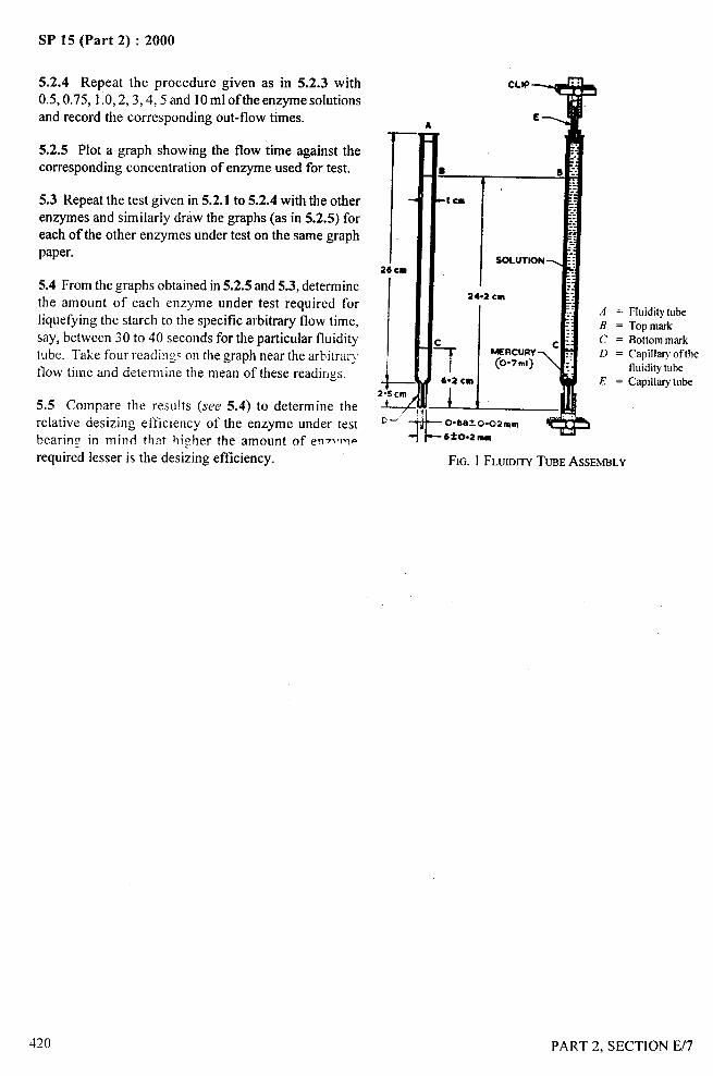
SP 15 (Part 2) :2000
5.2.4 Repeat the procedure given as in 5.2.3 with0.5,0.75, 1.0,2,3,4,5 and 10 ml of the enzyme solutionsand record the corresponding out-flow times.
5.2.5 Plot a graph showing the flow time against thecorresponding concentration of enzyme used for test.
5.3 Repeat the test given in 5.2.1 to 5.2.4 with the otherenzymes and similarly draw the graphs (as in 5.2.5) foreach of the other enzymes under test on the same graphpaper.
5.4 From the graphs obtained in 5.2.5 and 5.3, determinethe amount of each enzyme under test required for
liquefying the starch to the specific arbitrary flow time,say, between 30 to 40 seconds for the particular fluiditytube. Take four readings on the graph near the arbitrarjflow time and determine the mean of these readings.
5.5 Compare the results (see 5.4) to determine therelative desizing efficiency of the enzyme under testbearing in mind that higher the amount of enT~merequired lesser is the desizing efficiency.
D-
A
II
CLIP
E
—
u
●
24.2 cm
I
AB
f cD
SOLUTION -
——.————
——
FIG. 1 FLUIDITYTUBEASSEMBLY
Fluidity tube
Top mark
Bottom mark
Capill~ of the
fluidity tube
Capillary tube
PART 2, SECTION E/7