testing lte-advanced (release 10) - scdn.rohde-schwarz.com · introduction application note testing...
TRANSCRIPT

Testing LTE-Advanced (Rel. 10)Application Note
Products:
● R&S®SMW200A
● R&S®SMBV100A
● R&S®CMW500
● R&S®RTO-1044
● R&S®FSW
● R&S®FSV(R)
● R&S®FPS
● R&S®RTO
● R&S®TS8980
LTE-Advanced comprises multiple features enhancing the basic LTE technology firstly specified in 3GPPRelease 8. LTE including the LTE-Advanced improvements was approved by ITU to comply with IMT-Advanced requirements and thus being a true 4G mobile communication system. The different technologycomponents of LTE-Advanced have different market priorities and require different testing strategies.
This application note summarizes the Rohde & Schwarz test solutions for LTE-Advanced (Release 10)using Vector Signal Generators, Signal and Spectrum Analyzers and the Wideband Radio CommunicationTester.
Note:
Visit our homepage for the most recent version of this application note (www.rohde-schwarz.com/appnote/1MA166).
Appli
catio
n Note
Testing LTE Rel 10 ─ 1MA166_4e
Meik
Kottk
amp,
Bern
hard
Sch
ulz

Contents
2Application Note Testing LTE Rel 10 ─ 1MA166_4e
Contents1 Introduction............................................................................................ 3
2 Testing of LTE-Advanced (Rel. 10).......................................................4
3 Appendix...............................................................................................41
4 Rohde & Schwarz.................................................................................43
Introduction
3Application Note Testing LTE Rel 10 ─ 1MA166_4e
1 IntroductionLTE (Long Term Evolution) Release 8 standardization within the 3GPP (3rd Genera-tion Partnership Project) has come to a mature state where changes in the specifica-tion are limited to corrections and bug fixes. Since end 2009, LTE mobile communica-tion systems are commercially deployed as an evolution of GSM (Global system formobile communications), UMTS (Universal Mobile Telecommunications System),CDMA2000 (Code Division Multiple Access) and TD-SCDMA (Time Division Synchro-nous Code Division Multiple Access) networks.
The ITU (International Telecommunication Union) coined the term IMT-Advanced toidentify mobile systems whose capabilities go beyond those of IMT 2000 (InternationalMobile Telecommunications). In September 2009 the 3GPP Partners made a formalsubmission to the ITU proposing that LTE Release 10 & beyond (LTE-Advanced)should be evaluated as a candidate for IMT-Advanced. In October 2010 LTE-Advanced successfully completed the evaluation process in ITU-R complying with orexceeding the IMT-Advanced requirements and thus became an acknowledged 4Gtechnology. A complete LTE-Advanced technology introduction is available with aRohde & Schwarz white paper [1].
The different LTE-Advanced technology components illustrated in [1] naturally have dif-ferent market requirements and also require different testing strategies. Section 2 ofthis application note discusses the testing aspects of each technology component inLTE-Advanced and describes available test solutions in the Rohde & Schwarz productportfolio.
The following abbreviations are used in this application note for Rohde & Schwarz testequipment:
● The R&S®SMW200A vector signal generator is referred to as the SMW.● The R&S®SMBV100A vector signal generator is referred to as the SMBV.● The R&S®FSW signal and spectrum analyzer is referred to as the FSW.● The R&S®FSV spectrum analyzer is referred to as the FSV.● The R&S®FPS spectrum analyzer is referred to as the FPS.● The SMW and SMBV are referred to as the SMx.● The FSW, FSV and FPS are referred to as the FSx.● The R&S®CMW500 wideband radio communication tester is referred to as
CMW500● The R&S®TS8980 LTE RF Test System is referred to as TS8980
Testing of LTE-Advanced (Rel. 10)
4Application Note Testing LTE Rel 10 ─ 1MA166_4e
2 Testing of LTE-Advanced (Rel. 10)
2.1 LTE-A features (Release 10)
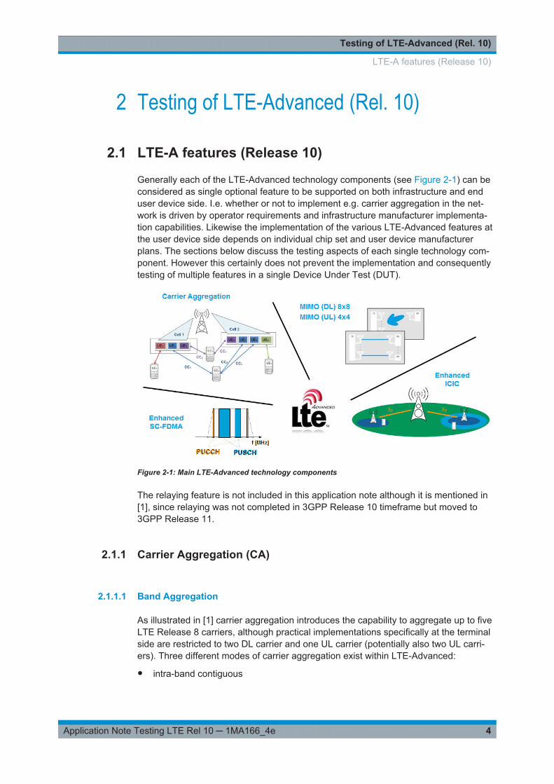
Generally each of the LTE-Advanced technology components (see Figure 2-1) can beconsidered as single optional feature to be supported on both infrastructure and enduser device side. I.e. whether or not to implement e.g. carrier aggregation in the net-work is driven by operator requirements and infrastructure manufacturer implementa-tion capabilities. Likewise the implementation of the various LTE-Advanced features atthe user device side depends on individual chip set and user device manufacturerplans. The sections below discuss the testing aspects of each single technology com-ponent. However this certainly does not prevent the implementation and consequentlytesting of multiple features in a single Device Under Test (DUT).
Figure 2-1: Main LTE-Advanced technology components
The relaying feature is not included in this application note although it is mentioned in[1], since relaying was not completed in 3GPP Release 10 timeframe but moved to3GPP Release 11.
2.1.1 Carrier Aggregation (CA)
2.1.1.1 Band Aggregation
As illustrated in [1] carrier aggregation introduces the capability to aggregate up to fiveLTE Release 8 carriers, although practical implementations specifically at the terminalside are restricted to two DL carrier and one UL carrier (potentially also two UL carri-ers). Three different modes of carrier aggregation exist within LTE-Advanced:
● intra-band contiguous
LTE-A features (Release 10)
Testing of LTE-Advanced (Rel. 10)
5Application Note Testing LTE Rel 10 ─ 1MA166_4e
● intra-band non-contiguous● inter-band
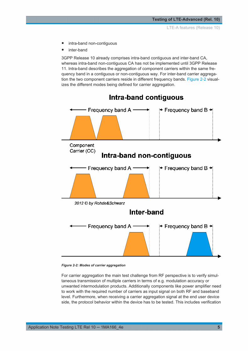
3GPP Release 10 already comprises intra-band contiguous and inter-band CA,whereas intra-band non-contiguous CA has not be implemented until 3GPP Release11. Intra-band describes the aggregation of component carriers within the same fre-quency band in a contiguous or non-contiguous way. For inter-band carrier aggrega-tion the two component carriers reside in different frequency bands. Figure 2-2 visual-izes the different modes being defined for carrier aggregation.
Figure 2-2: Modes of carrier aggregation
For carrier aggregation the main test challenge from RF perspective is to verify simul-taneous transmission of multiple carriers in terms of e.g. modulation accuracy orunwanted intermodulation products. Additionally components like power amplifier needto work with the required number of carriers as input signal on both RF and basebandlevel. Furthermore, when receiving a carrier aggregation signal at the end user deviceside, the protocol behavior within the device has to be tested. This includes verification
LTE-A features (Release 10)
Testing of LTE-Advanced (Rel. 10)
6Application Note Testing LTE Rel 10 ─ 1MA166_4e
of the scheduling signaling, measurement reporting, handover procedures and eventu-ally E2E performance, i.e. demonstrating data rate capabilities. From conformancetesting perspective a number of new certification tests are defined for RF, RRM andprotocol. Finally performance verification in the field is required.
2.1.1.2 HARQ ACK/NACK procedure for multiple cells, PUCCH format 3
The ACK/NACK feedback in the PUCCH signals correct reception of transport blocksin the downlink direction. PUCCH format 3 allows now ACK/NACK reporting for carrieraggregation scenarios resulting into multiple cells received by a single UE. It allows toACK/NACK multiple transport blocks on multiple carriers in a single extended mes-sage.
2.1.2 Enhanced SC-FDMA
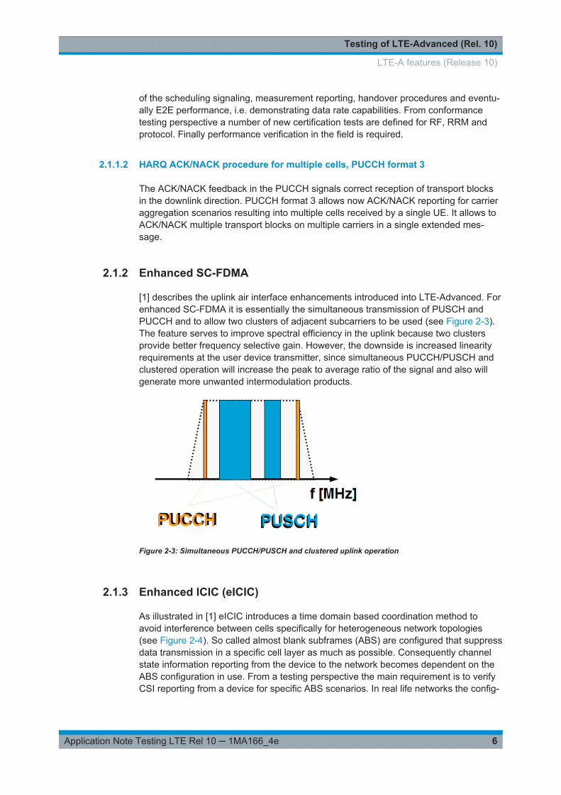
[1] describes the uplink air interface enhancements introduced into LTE-Advanced. Forenhanced SC-FDMA it is essentially the simultaneous transmission of PUSCH andPUCCH and to allow two clusters of adjacent subcarriers to be used (see Figure 2-3).The feature serves to improve spectral efficiency in the uplink because two clustersprovide better frequency selective gain. However, the downside is increased linearityrequirements at the user device transmitter, since simultaneous PUCCH/PUSCH andclustered operation will increase the peak to average ratio of the signal and also willgenerate more unwanted intermodulation products.
Figure 2-3: Simultaneous PUCCH/PUSCH and clustered uplink operation
2.1.3 Enhanced ICIC (eICIC)
As illustrated in [1] eICIC introduces a time domain based coordination method toavoid interference between cells specifically for heterogeneous network topologies(see Figure 2-4). So called almost blank subframes (ABS) are configured that suppressdata transmission in a specific cell layer as much as possible. Consequently channelstate information reporting from the device to the network becomes dependent on theABS configuration in use. From a testing perspective the main requirement is to verifyCSI reporting from a device for specific ABS scenarios. In real life networks the config-
LTE-A features (Release 10)

Testing of LTE-Advanced (Rel. 10)
7Application Note Testing LTE Rel 10 ─ 1MA166_4e
uration of ABS patterns is operator and/or infrastructure dependent. This requires aflexible test environment to be configured according to individual testing needs.
Figure 2-4: Heterogeneous network topology
Generally the behavior of the device under test has to be verified and therefore RFonly measurements based on signal generators and signal analyzers are not required.
2.1.4 Enhanced MIMO schemes
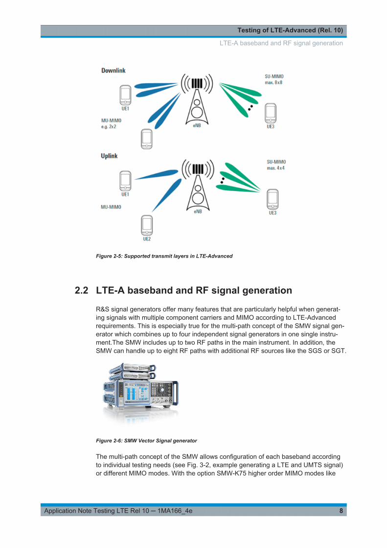
LTE Release 8 supports multiple input / output (MIMO) antenna schemes. In downlinkdirection up to four transmit antennas may be used whereas the maximum number ofcodewords is two irrespective of the number of antenna ports. In uplink direction onlyMU-MIMO is used, i.e. there is only one modulated symbol stream per UE to bereceived by the eNodeB, whereas multiple UEs may transmit on the same time-fre-quency resource. LTE-Advanced extends the MIMO capabilities of LTE Release 8 tonow supporting (see Figure 2-5,[1]):
● Downlink: eight (8) layers● Uplink: four (4) layers
To support up to eight layers in the downlink, the new transmission mode (TM) 9 wasintroduced.
The enhanced downlink scheme is an extension of the existing scheme and in uplinkdirection the existing downlink scheme is essentially reused. Consequently testing theenhanced MIMO schemes requires similar methods than known from LTE Release 8.A description on how to generate and analyze MIMO signals is available in [4].
LTE-A features (Release 10)
Testing of LTE-Advanced (Rel. 10)
8Application Note Testing LTE Rel 10 ─ 1MA166_4e
Figure 2-5: Supported transmit layers in LTE-Advanced
2.2 LTE-A baseband and RF signal generation
R&S signal generators offer many features that are particularly helpful when generat-ing signals with multiple component carriers and MIMO according to LTE-Advancedrequirements. This is especially true for the multi-path concept of the SMW signal gen-erator which combines up to four independent signal generators in one single instru-ment.The SMW includes up to two RF paths in the main instrument. In addition, theSMW can handle up to eight RF paths with additional RF sources like the SGS or SGT.
Figure 2-6: SMW Vector Signal generator
The multi-path concept of the SMW allows configuration of each baseband accordingto individual testing needs (see Fig. 3-2, example generating a LTE and UMTS signal)or different MIMO modes. With the option SMW-K75 higher order MIMO modes like
LTE-A baseband and RF signal generation

Testing of LTE-Advanced (Rel. 10)
9Application Note Testing LTE Rel 10 ─ 1MA166_4e
8x4, 4x8 and 4x4 for 2 component carriers (CC) are possible. As an option in additionfading is available.
Figure 2-7: SMW example with four different signals
The SMW-K85 option allows testing of LTE-Advanced physical layer features in linewith the 3GPP Release 10 standard. It covers downlink and uplink signal generation.SMW-K85 requires the basic LTE functionality being installed on the equipment (SMW-K55 LTE option).
LTE-A baseband and RF signal generation
Testing of LTE-Advanced (Rel. 10)
10Application Note Testing LTE Rel 10 ─ 1MA166_4e
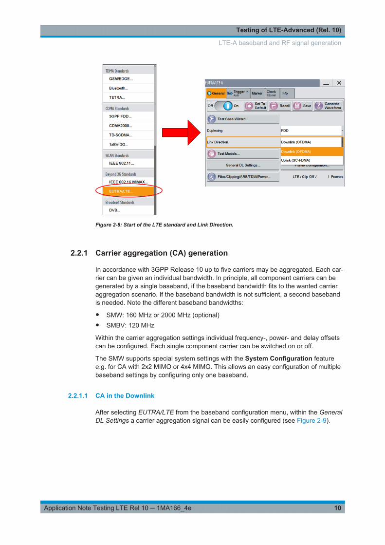
Figure 2-8: Start of the LTE standard and Link Direction.
2.2.1 Carrier aggregation (CA) generation
In accordance with 3GPP Release 10 up to five carriers may be aggregated. Each car-rier can be given an individual bandwidth. In principle, all component carriers can begenerated by a single baseband, if the baseband bandwidth fits to the wanted carrieraggregation scenario. If the baseband bandwidth is not sufficient, a second basebandis needed. Note the different baseband bandwidths:
● SMW: 160 MHz or 2000 MHz (optional)● SMBV: 120 MHz
Within the carrier aggregation settings individual frequency-, power- and delay offsetscan be configured. Each single component carrier can be switched on or off.
The SMW supports special system settings with the System Configuration featuree.g. for CA with 2x2 MIMO or 4x4 MIMO. This allows an easy configuration of multiplebaseband settings by configuring only one baseband.
2.2.1.1 CA in the Downlink
After selecting EUTRA/LTE from the baseband configuration menu, within the GeneralDL Settings a carrier aggregation signal can be easily configured (see Figure 2-9).
LTE-A baseband and RF signal generation
Testing of LTE-Advanced (Rel. 10)
11Application Note Testing LTE Rel 10 ─ 1MA166_4e
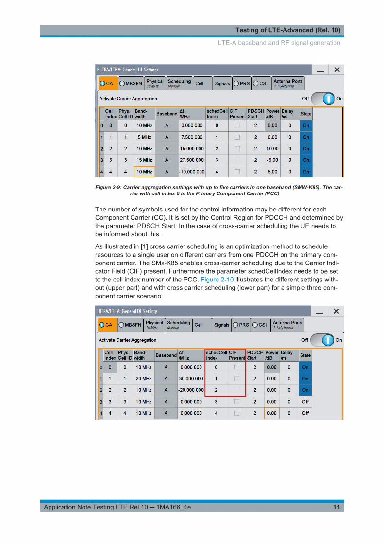
Figure 2-9: Carrier aggregation settings with up to five carriers in one baseband (SMW-K85). The car-rier with cell index 0 is the Primary Component Carrier (PCC)
The number of symbols used for the control information may be different for eachComponent Carrier (CC). It is set by the Control Region for PDCCH and determined bythe parameter PDSCH Start. In the case of cross-carrier scheduling the UE needs tobe informed about this.
As illustrated in [1] cross carrier scheduling is an optimization method to scheduleresources to a single user on different carriers from one PDCCH on the primary com-ponent carrier. The SMx-K85 enables cross-carrier scheduling due to the Carrier Indi-cator Field (CIF) present. Furthermore the parameter schedCellIndex needs to be setto the cell index number of the PCC. Figure 2-10 illustrates the different settings with-out (upper part) and with cross carrier scheduling (lower part) for a simple three com-ponent carrier scenario.
LTE-A baseband and RF signal generation
Testing of LTE-Advanced (Rel. 10)
12Application Note Testing LTE Rel 10 ─ 1MA166_4e
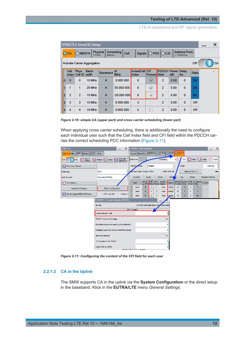
Figure 2-10: simple CA (upper part) and cross carrier scheduling (lower part)
When applying cross carrier scheduling, there is additionally the need to configureeach individual user such that the Cell Index field and CFI field within the PDCCH car-ries the correct scheduling PCC information (Figure 2-11).
Figure 2-11: Configuring the content of the CFI field for each user
2.2.1.2 CA in the Uplink
The SMW supports CA in the uplink via the System Configuration or the direct setupin the baseband. Klick in the EUTRA/LTE menu General Settings.
LTE-A baseband and RF signal generation
Testing of LTE-Advanced (Rel. 10)
13Application Note Testing LTE Rel 10 ─ 1MA166_4e
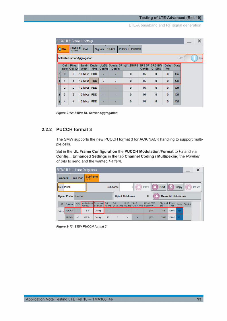
Figure 2-12: SMW: UL Carrier Aggregation
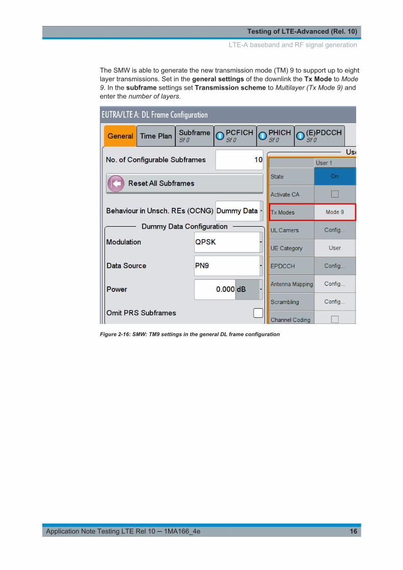
2.2.2 PUCCH format 3
The SMW supports the new PUCCH format 3 for ACK/NACK handling to support multi-ple cells.
Set in the UL Frame Configuration the PUCCH Modulation/Format to F3 and viaConfig... Enhanced Settings in the tab Channel Coding / Multipexing the Numberof Bits to send and the wanted Pattern.
Figure 2-13: SMW PUCCH format 3
LTE-A baseband and RF signal generation

Testing of LTE-Advanced (Rel. 10)
14Application Note Testing LTE Rel 10 ─ 1MA166_4e
Figure 2-14: SMW: Set the bits to transmit in PUCCH format 3
2.2.3 Enhanced SC-FDMA generation
In order to test e.g. the linearity of a power amplifier design, one would need to gener-ate a 3GPP Release 10 compliant enhanced SC-FDMA signal. This is part of the K85LTE-Advanced option offered for SMx. After selecting EUTRA/LTE from the basebandconfiguration menu use the Frame Configuration menu to configure an individual userdevice.
The General section allows selecting either LTE Rel 8/9 or LTE Rel 10. When usingRel 10 per UE the content field shows simultaneous PUCCH and PUSCH. Two sets ofresource blocks can be configured in accordance with 3GPP specifications as illustra-ted in Figure 2-15.
LTE-A baseband and RF signal generation

Testing of LTE-Advanced (Rel. 10)
15Application Note Testing LTE Rel 10 ─ 1MA166_4e
Figure 2-15: Configuring Clustered PUSCH and simultaneous PUCCH/PUSCH
2.2.4 Enhanced MIMO generation
For MIMO tests vector signal generators need to generate different antenna signalssimultaneously in parallel. In addition the complete MIMO transmission channel withfading can be simulated.
The SMW can generate up to eight antenna signals simultaneously in its digital base-band – all LTE standard-compliant and with antenna-specific coding. In addition, it cansimulate the complete MIMO transmission channel with up to 16 fading channels, suffi-cient to emulate higher-order MIMO configurations such as 4x4. With the option SMW-K75 higher order MIMO modes like 8x4, 4x8 and 4x4 for 2 component carriers (CC)are possible. As an option in addition fading is available.
The SMBV is able to generate one baseband signal.
2.2.4.1 MIMO in Downlink
With the SMW LTE can generate up to 4x4 MIMO configuration with the needed 16real time fading channels or a Carrier Aggregation scenario with two component carri-ers and 2x2 MIMO with independent fading with eight fading channels.
The system configuration feature of the SMW simplifies the necessary settings. For a4x4 MIMO test a configuration of 1 x 4 x 4 is necessary, for a CA 4x4 MIMO test aconfiguration of 2 x 4 x 4.
Both tests are described in detail in [5].
LTE-A baseband and RF signal generation
Testing of LTE-Advanced (Rel. 10)
16Application Note Testing LTE Rel 10 ─ 1MA166_4e
The SMW is able to generate the new transmission mode (TM) 9 to support up to eightlayer transmissions. Set in the general settings of the downlink the Tx Mode to Mode9. In the subframe settings set Transmission scheme to Multilayer (Tx Mode 9) andenter the number of layers.
Figure 2-16: SMW: TM9 settings in the general DL frame configuration
LTE-A baseband and RF signal generation

Testing of LTE-Advanced (Rel. 10)
17Application Note Testing LTE Rel 10 ─ 1MA166_4e
Figure 2-17: SMW: TM9 in the enhanced settings of the subframe, here with four layers
2.2.4.2 MIMO in Uplink
In the uplink up to 4x4 MIMO can be handled in one single SMW (with 2 SGS exten-sions). Basestation tests use a 2x2 or 2x4 configuration.
As an example a 2x2 MIMO uplink signal is created.
Select in the System Configuration 1 x 2 x 2 and Coupled sources. This simplifies thesettings by configuring the settings in one baseband only.
LTE-A baseband and RF signal generation

Testing of LTE-Advanced (Rel. 10)
18Application Note Testing LTE Rel 10 ─ 1MA166_4e
Figure 2-18: The system configuration for a 2x2 Uplink MIMO is 1 x 2 x 2
In the baseband select EUTRA/LTE and set Link Direction to Uplink (SC-FDMA). Thebutton Frame Configurations shows the already enabled UE1. Open the User Equip-ment configuration by clicking on the UE1.
In the PUSCH set the Transmission Mode (TM) to TM2 and the number of AntennaPorts (in this example 2). Check the Antenna Port mapping. Baseband A generates thePUSCH for AP20, Baseband B for AP21 (see Figure 2-19).
Figure 2-19: The Transmission Mode 2 enables Spatial Multiplexing with up to four antennas (exam-ple 2 antennas)
In the Subframe section configure the two codewords (CW), e.g. Modulation andresource block allocation (Figure 2-20). In the enhanced settings Configuration set
LTE-A baseband and RF signal generation

Testing of LTE-Advanced (Rel. 10)
19Application Note Testing LTE Rel 10 ─ 1MA166_4e
the codebook index. For the available codebook indices please see [1]. Please notethat for two layers only one codebook index is available (CB 0).
Figure 2-20: Setting the two independent codewords.
Figure 2-21: Overview of the MIMO settings in the enhanced settings.
2.3 LTE-A signal analysis
For measuring LTE(-A) signals, several different spectrum analyzers can be used forthe tests described here:
● FSW
LTE-A signal analysis

Testing of LTE-Advanced (Rel. 10)
20Application Note Testing LTE Rel 10 ─ 1MA166_4e
● FSV(R)● FPS
The E-UTRA/LTE measurements software option is available for each of the listedanalyzers. The following are available:
● FSx-K100 E-UTRA/LTE FDD downlink measurements● FSx-K101 E-UTRA/LTE FDD uplink measurements● FSx-K102 E-UTRA/LTE downlink MIMO measurements● FSx-K104 E-UTRA/LTE TDD downlink measurements● FSx-K105 E-UTRA/LTE TDD uplink measurements● FSx-K103 Analysis of EUTRA LTE-Advanced and MIMO Uplink Signals
Test instruments can also be controlled via the external PC software application E-UTRA/LTE and LTE-Advanced Signal Analysis. The options are named FS-K10xPC.With the software in addition to the above mentioned spectrum analyzers, the oscillo-scopes of the RTO family can be used.
Figure 2-22: Using the RTO for MIMO measurements
Figure 2-22 shows that with FS-K10xPC software it is also possible to use RTO oscil-loscopes for capturing IQ data as input for the analysis software. This is in particularconvenient since the RTO offers up to four input channels.
2.3.1 Carrier aggregation (CA) analysis
When a carrier aggregation signal comprising multiple component carriers is transmit-ted, each carrier needs to be tested on RF level the same way as in LTE Release 8.,e.g. EVM and frequency error measurements. Maximum power measurements need tobe performed across all component carriers operated by the base station according tomanufacturer declaration. Adjacent band and out of band requirements like transmitintermodulation, ACLR or spurious emissions have to be measured using the mostdemanding carrier aggregation configuration. E.g. the lower and upper most compo-nent carrier is to be switched on, when verifying the corresponding limits for transmitintermodulation tests. Measurements can be done with option FSx-K100/104 (FDD/TDD) on the Rohde & Schwarz signal analyzer family based on high range signal andspectrum analyzer FSW / FSQ or mid-range signal and spectrum analyzers FSG,FSV(R). Note that testing capabilities will be adapted according to 3GPP develop-ments. See Figure 2-23 providing an example for LTE measurements on a single com-ponent carrier.
LTE-A signal analysis
Testing of LTE-Advanced (Rel. 10)
21Application Note Testing LTE Rel 10 ─ 1MA166_4e
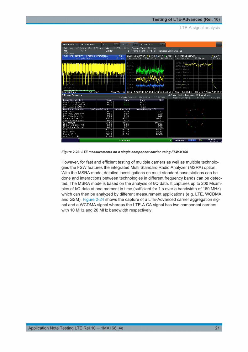
Figure 2-23: LTE measurements on a single component carrier using FSW-K100
However, for fast and efficient testing of multiple carriers as well as multiple technolo-gies the FSW features the integrated Multi Standard Radio Analyzer (MSRA) option.With the MSRA mode, detailed investigations on multi-standard base stations can bedone and interactions between technologies in different frequency bands can be detec-ted. The MSRA mode is based on the analysis of I/Q data. It captures up to 200 Msam-ples of I/Q data at one moment in time (sufficient for 1 s over a bandwidth of 160 MHz)which can then be analyzed by different measurement applications (e.g. LTE, WCDMAand GSM). Figure 2-24 shows the capture of a LTE-Advanced carrier aggregation sig-nal and a WCDMA signal whereas the LTE-A CA signal has two component carrierswith 10 MHz and 20 MHz bandwidth respectively.
LTE-A signal analysis
Testing of LTE-Advanced (Rel. 10)
22Application Note Testing LTE Rel 10 ─ 1MA166_4e
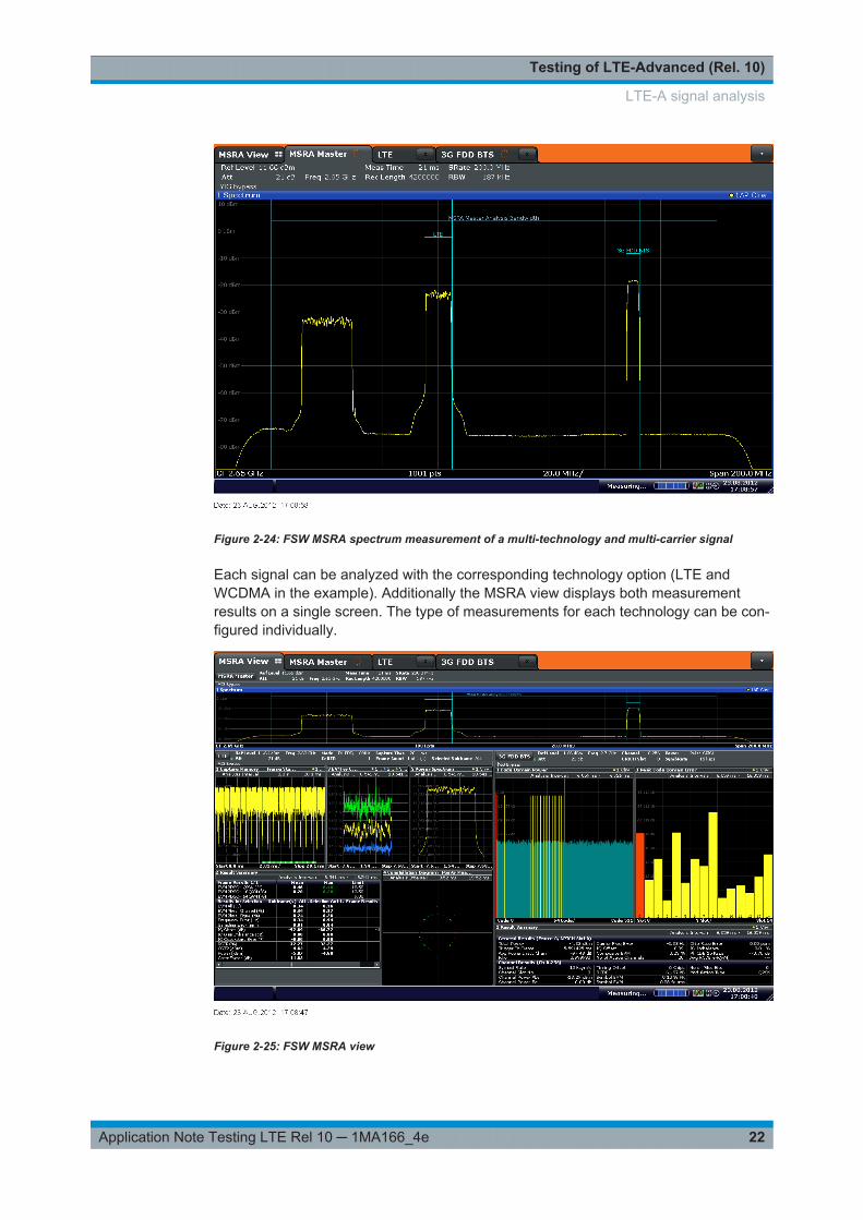
Figure 2-24: FSW MSRA spectrum measurement of a multi-technology and multi-carrier signal
Each signal can be analyzed with the corresponding technology option (LTE andWCDMA in the example). Additionally the MSRA view displays both measurementresults on a single screen. The type of measurements for each technology can be con-figured individually.
Figure 2-25: FSW MSRA view
LTE-A signal analysis

Testing of LTE-Advanced (Rel. 10)
23Application Note Testing LTE Rel 10 ─ 1MA166_4e
The MSRA function as an integrated feature in each FSW is also useful for measuringa LTE-Advanced carrier aggregation signal. Figure 2-26 shows a five component car-rier signal with different bandwidth configurations and power offsets. Those carriers ofinterest may be analyzed configuring different measurements on each carrier accord-ing to individual testing needs. Figure 2-25 shows the example of analyzing two out ofthe five carriers.
Figure 2-26: MSRA master view of a five component LTE-A carrier aggregation signal
LTE-A signal analysis

Testing of LTE-Advanced (Rel. 10)
24Application Note Testing LTE Rel 10 ─ 1MA166_4e
Figure 2-27: MSRA view with different measurements on two of the five components
The MSRA gives R&D engineers valuable insight because it is very easy to find crosstalks between different carriers by detecting time correlations between different signals.This becomes possible, since the analysis is performed on the same set of recordedI/Q data.
Time Alignment
Also infrastructure suppliers have to perform dedicated tests for carrier aggregation.One of them is the time alignment error measurement, short TAE. As frames of LTEsignals at a base station antenna port are not perfectly aligned, they need to fulfill cer-tain timing requirements. For intra-band carrier aggregation this TAE shall not exceed155 ns. Inter-band carrier aggregation allows an error of up to 285 ns. These require-ments are independent of TX diversity or MIMO applied per component carrier. Fig-ure 2-28 shows the required setup to measure the time alignment error. The externalPC software LTE FS-K102PC can be used to control different instruments like the RTOor more than one spectrum analyzer. A stand-alone FSx can be used to measure theTAE if the RF analysis bandwidth is sufficient (e.g. the FSW has a bandwidth up to2000 MHz). Further details can be found in the related 3GPP specification for LTEbase station RF conformance testing [3].
LTE-A signal analysis

Testing of LTE-Advanced (Rel. 10)
25Application Note Testing LTE Rel 10 ─ 1MA166_4e
Figure 2-28: different setups measuring TAE for carrier aggregation
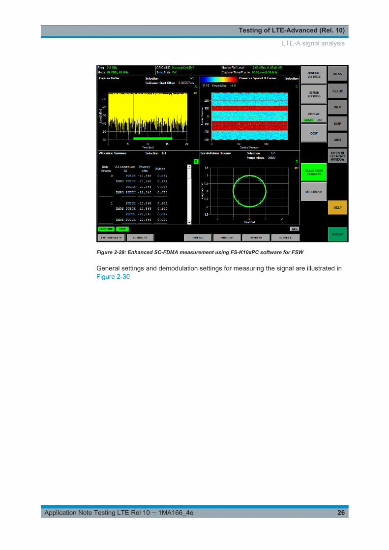
2.3.2 Enhanced SC-FDMA analysis
From an RF perspective the main test requirement for enhanced SC-FDMA is to mea-sure the modulation accuracy if both PUCCH and PUSCH are transmitted simultane-ously.
Figure 2-29 shows an example measurement using the FS-K10xPC software on top ofFSW. FS-K10xPC offers convenient signal analysis due to automatic detection of mod-ulation formats. Each signal subframe is analyzed and the QPSK, 16QAM or 64QAM(DL only) modulation formats plus the length of the cyclic prefix are automaticallydetected and used in the analysis. Note that whether FS-K10xPC is installed on theinstrument or on an external PC, the measurements can be fully automated using well-known SCPI commands. This makes FS-K10xPC ideal for use in automated test sys-tems.
LTE-A signal analysis
Testing of LTE-Advanced (Rel. 10)
26Application Note Testing LTE Rel 10 ─ 1MA166_4e
Figure 2-29: Enhanced SC-FDMA measurement using FS-K10xPC software for FSW
General settings and demodulation settings for measuring the signal are illustrated inFigure 2-30
LTE-A signal analysis

Testing of LTE-Advanced (Rel. 10)
27Application Note Testing LTE Rel 10 ─ 1MA166_4e
Figure 2-30: Demodulation settings for enhanced SC-FDMA
2.3.3 Enhanced MIMO analysis
MIMO signals are used in LTE-A in the downlink and uplink direction. Both ways canbe measured with signal analyzers or the RTO.
Figure 2-31: Test setup with an RTO for measuring a MIMO signal
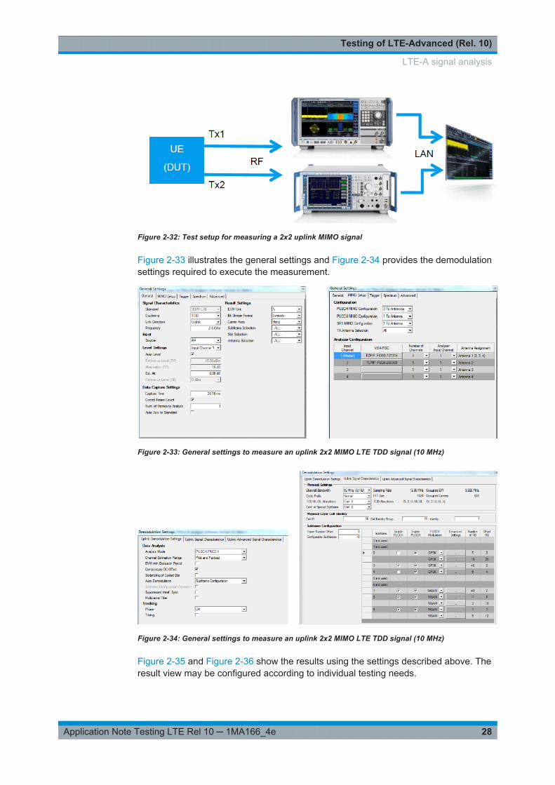
From an RF perspective one of the measurement tasks for enhanced MIMO schemesis to test an uplink 2x2 signal with regards to modulation accuracy. As the new uplinkscheme is similar to the MIMO scheme in downlink direction, testing needs are equallycomparable (for comparison see [4]). In order to measure the uplink 2x2 MIMO signaltwo analyzers or one RTO are required. Figure 2-32 illustrates the principle test setupusing as an example a FSW and a FSQ for capturing the IQ data and FS-K10xPC soft-ware to analyze the results. For this example an uplink LTE TDD signal is analyzed.
LTE-A signal analysis
Testing of LTE-Advanced (Rel. 10)
28Application Note Testing LTE Rel 10 ─ 1MA166_4e
Figure 2-32: Test setup for measuring a 2x2 uplink MIMO signal
Figure 2-33 illustrates the general settings and Figure 2-34 provides the demodulationsettings required to execute the measurement.
Figure 2-33: General settings to measure an uplink 2x2 MIMO LTE TDD signal (10 MHz)
Figure 2-34: General settings to measure an uplink 2x2 MIMO LTE TDD signal (10 MHz)
Figure 2-35 and Figure 2-36 show the results using the settings described above. Theresult view may be configured according to individual testing needs.
LTE-A signal analysis

Testing of LTE-Advanced (Rel. 10)
29Application Note Testing LTE Rel 10 ─ 1MA166_4e
Figure 2-35: Power versus time / frequency measurements, EVM measurements and constellationdiagram for each Tx antenna summarized in the multiple screen view
Figure 2-36: EVM measurements in tabular format for one selected TX antenna in single screen view
LTE-A signal analysis

Testing of LTE-Advanced (Rel. 10)
30Application Note Testing LTE Rel 10 ─ 1MA166_4e
2.4 LTE-A with the CMW500
The CMW can be used as a protocol tester (message analysis) as well as a radio com-munication tester (call box, RF test).
In addition to LTE-A, the CMW offers other radio communication standards, includingW-CDMA (with HSPA+), GSM, CDMA2000, 1x-EV-DO and so on. This makes it possi-ble to test InterRAT scenarios, such as LTE handover to GSM or W-CDMA.
Equipped with powerful hardware and various interfaces to wireless devices, the CMWcan be used throughout all phases of LTE-A device development – from the initialmodule test up to the integration of software and chipset, as well as for conformanceand performance tests of the protocol stack of 3GPP standard-compliant wireless devi-ces, see Figure 2-37
Figure 2-37: Consistent hardware and software concept for all device development phases.
MIMO and Carrier Aggregation
The CMW (protocol tester and callbox) supports different transmission and MIMOmodes like 8x2 MIMO and carrier aggregation up to five (5) component carriers (CC)and MIMO in parallel like CA with 4x4 MIMO. The CMW supports all possible fre-quency allocations in CA (intra-band contiguous, intra-band non- contiguous and inter-band). All CC’s can be set up independently of each other.
Carrier Aggregation with CMWflexx
The CMWflexx provides more than 2 CC’s with MIMO each, therefore more than oneCMW is used. The CMW Controller (CMWC) allows easy manual and remote control, itacts like one CMW with extended RF hardware.
LTE-A with the CMW500

Testing of LTE-Advanced (Rel. 10)
31Application Note Testing LTE Rel 10 ─ 1MA166_4e
2.4.1 LTE-A in the CMW protocol tester
The device under test (a chip set or terminal) is connected to a network emulator,which simulates all required network functions and protocols. However, errors mayoccur in all layers (physical layer, Layer 2/3, application layer) and throughout thewhole development cycle (R&D, conformance, production). Thus any test instrumentneeds to offer manifold analysis capabilities. Rohde & Schwarz offers the CMW500wideband radio communication tester, which provides all necessary functions within asingle test instrument.
Different bandwidths per component carrier, up to 20 MHz each, are supported.CMW500 supports all variances of carrier aggregation in one single instrument: intra-band (contiguous, non-contiguous) and inter-band. Already today the instrument sup-ports all 3GPP frequency bands that are utilized for LTE.
First of all the tester and the DUT have to run throughout a successful LTE-A channelsetup. I.e. the signaling procedure from starting with a LTE Rel8 setup and adding sec-ondary component carriers (SCC’s) has to be verified on all relevant protocol layers(PHY, MAC and RRC). This would typically be done using a CMW500 in protocol testconfiguration. Example scenarios are available for lower layer API (LLAPI) andmedium layer API (MLAPI) as well as the graphical user interface CMWcards. Fig-ure 2-38 shows example physical layer scenarios using different configurations for pri-mary and secondary cells as well as different transmission modes.
Figure 2-38: Physical layer example scenario for carrier aggregation
LTE-A with the CMW500
Testing of LTE-Advanced (Rel. 10)
32Application Note Testing LTE Rel 10 ─ 1MA166_4e
MLAPI
In order to verify the signaling communication on layer 2 and 3, MLAPI scenarios areavailable. These can be used as provided in various test scenario packages. Addition-ally existing scenarios may be modified according to the individual testing needs.
Following MLAPI scenarios packages with Release 10 features are available:
Table 2-1: MLAPI Scenario Packages Rel 10
Scenario Packages Rel 10
Name Description Remark
PHY and L2 Verification
CMW-KF513 CA / eICIC
CMW-KF518 3 CA DL / CoMP / TM10
Full Stack Verification
CMW-KF514 CA Mobility
CMW-KF515 eICIC / feICIC
CMW-KU503 LTE Rel. 9-12 MTC MLAPI Scenario PACK, MTC-, IoT-, M2M-TestScenarios to test CAT0, EAB, Extended Wait Time
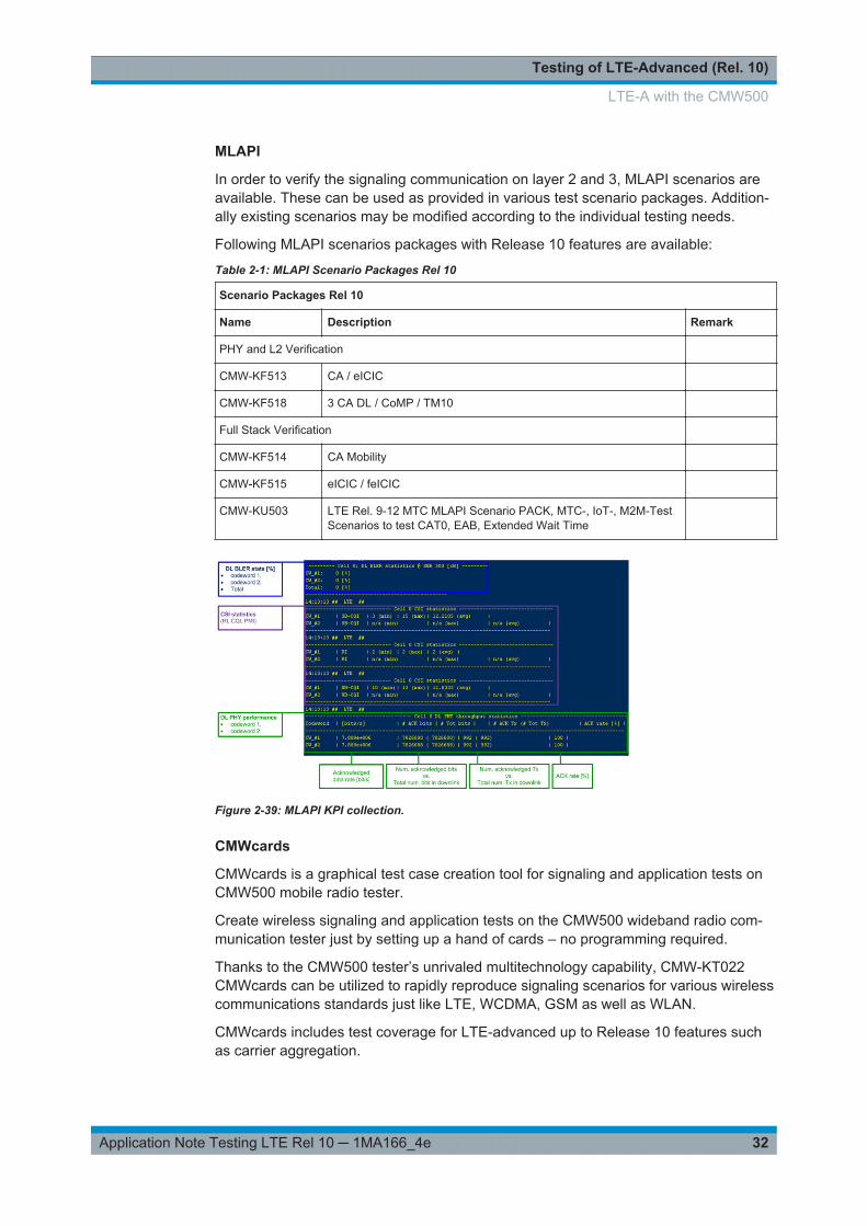
Figure 2-39: MLAPI KPI collection.
CMWcards
CMWcards is a graphical test case creation tool for signaling and application tests onCMW500 mobile radio tester.
Create wireless signaling and application tests on the CMW500 wideband radio com-munication tester just by setting up a hand of cards – no programming required.
Thanks to the CMW500 tester’s unrivaled multitechnology capability, CMW-KT022CMWcards can be utilized to rapidly reproduce signaling scenarios for various wirelesscommunications standards just like LTE, WCDMA, GSM as well as WLAN.
CMWcards includes test coverage for LTE-advanced up to Release 10 features suchas carrier aggregation.
LTE-A with the CMW500

Testing of LTE-Advanced (Rel. 10)
33Application Note Testing LTE Rel 10 ─ 1MA166_4e
Figure 2-40: Overview CMWcards
CMWmars
Efficiently analyze recorded message logfiles. The convenient, intuitive CMWmarsmessage analyzer user interface combined with various tools and views helps usersquickly narrow down the root cause of signaling protocol and lower layer problems.The multifunctional logfile analyzer provides access to all information elements of allprotocol layers for LTE, WCDMA, GSM, TD-SCDMA, CDMA2000® and WLAN, includ-ing the IP layer. CMWmars presents the logfile in various synchronized views that visu-alize the data from different perspectives, helping users to postprocess complex mes-sage logs in a very intuitive and easy way.
LTE-A with the CMW500

Testing of LTE-Advanced (Rel. 10)
34Application Note Testing LTE Rel 10 ─ 1MA166_4e
Figure 2-41: Overview CMWmars.
Uplink – TX Measurements
Furthermore there is a need to verify the uplink signal transmitted by the device whenin downlink direction e.g. two component carriers are received. All relevant measure-ments are available with the CMW500. The RF uplink measurements can be done inparallel to a MLAPI test scenario or in the RF tester environment. These measure-ments do not differ from LTE Release 8 uplink TX measurements if only one uplink car-rier is used. The CMW also supports uplink carrier aggregation measurements (seenext section).
2.4.2 LTE-A in the CMW RF tester ("call box")
When used as an RF tester, the CMW provides a generator for the LTE downlink andan analyzer for the LTE uplink signal. The CMW can also emulate network operation(“signaling”) under realistic conditions for RF tests. The CMW supports carrier aggre-gation up to five (5) component carriers (CC) and MIMO in parallel like CA with 4x4MIMO (CMWflexx).
2.4.2.1 Transmitter tests (TX)
Measurements on the TX side of the DUT are made possible with the LTE Multi Evalu-ation option (see Figure 2-42).
The overview screen provides all measured results and scalar values for the essentialmeasurements: UE power, error vector magnitude (EVM) root mean square (RMS)
LTE-A with the CMW500

Testing of LTE-Advanced (Rel. 10)
35Application Note Testing LTE Rel 10 ─ 1MA166_4e
power, RB allocation table and spectrum measurements. Because measurementsresults are based on the same set of data, the individual results relate to each other,thus facilitating troubleshooting and debugging.
Figure 2-42: Tx measurements of a DUT uplink signal using CMW500
The overview display in multi-evaluation mode can be adapted to the individual testingneeds. For example, it may be necessary to closely monitor only two measurementresults, or just one measurement result with a comparison of maximum and averagevalues. The overview display can be configured to meet individual needs.
These measurements do not differ from LTE Release 8 uplink TX measurements ifonly one uplink carrier is used. If two uplink carriers are used, the modulation measure-ments, e.g. EVM, can be done on each CC. Measurements like inband emission,power monitor and RB allocation table can be done at the same time. Spectrum mea-surements (Spectrum ACLR and Spectrum emission mask) are measured for theaggregated bandwidth for CC’s together for intra-band contiguous uplink CA.
2.4.2.2 Signaling and receiver tests (RX)
The CMW can optionally provide signaling. The "LTE signaling" firmware application(option KS5xx) allows users to emulate an E-UTRA cell and to communicate with theUE under test. The UE can synchronize to the DL signal and register.
This means that RX tests, e.g. ACK/NACK measurements (BLER, throughput), can beperformed in test mode on the DUT.
LTE-A with the CMW500

Testing of LTE-Advanced (Rel. 10)
36Application Note Testing LTE Rel 10 ─ 1MA166_4e
Figure 2-43: LTE RX measurement for Carrier Aggregation. The throughput for both CCs and theoverall throughput are displayed.
End-to-end data tests can be performed using the DAU (see the next section).
2.4.3 Data Application Unit (DAU) for CMW
The "Data Application Unit" (option B450A) makes it possible to test data transfer viaTCP/IP or UDP/IP. It allows users to run Internet Protocol (IP) services on the CMW,such as file transfer and Web browsing. The DAU provides a common and consistentdata testing solution on the CMW for all supported radio access technologies.
The DAU is required when testing End-to-End (E2E) IP data transfer as well as whenusing the instrument for protocol testing (U-plane tests). Together with the DAU, IP-based measurement (option KM050) applications allow users to test and measure theproperties of the IP connection, such as network latency or performance. The mea-surements support Internet protocols IPv4 (option KA100) and IPv6 (option KA150 ontop of KA100).
LTE-A with the CMW500
Testing of LTE-Advanced (Rel. 10)
37Application Note Testing LTE Rel 10 ─ 1MA166_4e
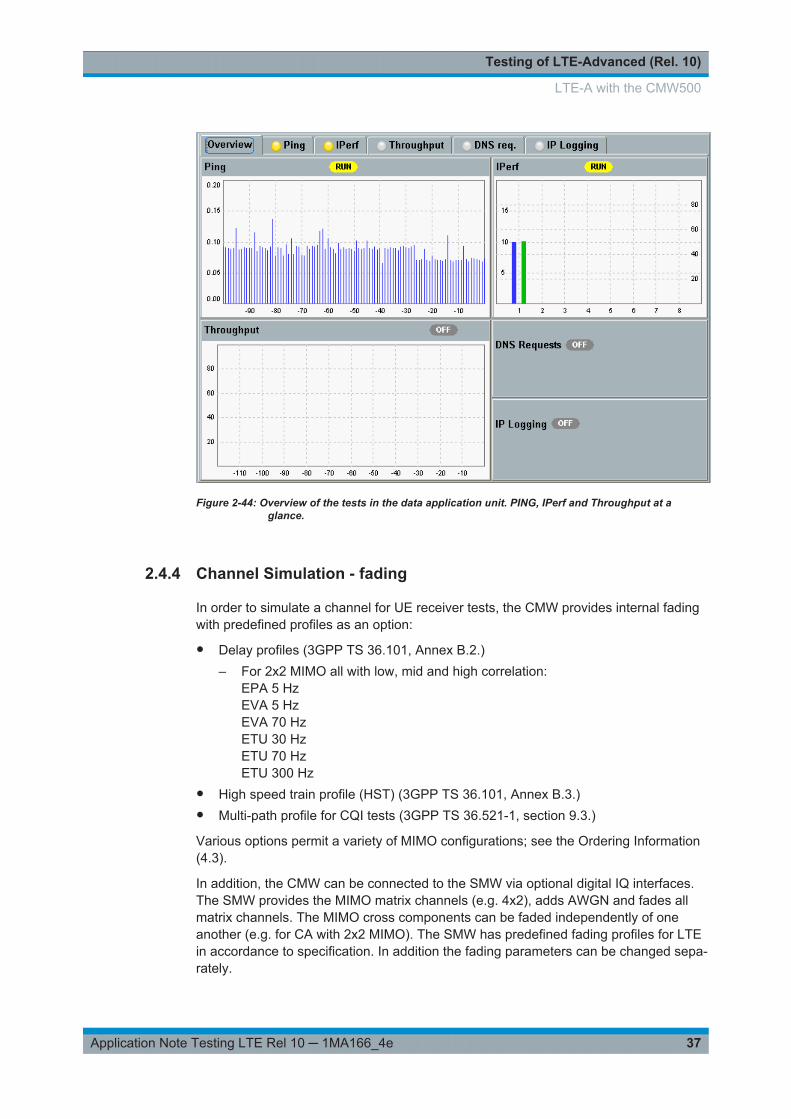
Figure 2-44: Overview of the tests in the data application unit. PING, IPerf and Throughput at aglance.
2.4.4 Channel Simulation - fading
In order to simulate a channel for UE receiver tests, the CMW provides internal fadingwith predefined profiles as an option:
● Delay profiles (3GPP TS 36.101, Annex B.2.)– For 2x2 MIMO all with low, mid and high correlation:
EPA 5 HzEVA 5 HzEVA 70 HzETU 30 HzETU 70 HzETU 300 Hz
● High speed train profile (HST) (3GPP TS 36.101, Annex B.3.)● Multi-path profile for CQI tests (3GPP TS 36.521-1, section 9.3.)
Various options permit a variety of MIMO configurations; see the Ordering Information(4.3).
In addition, the CMW can be connected to the SMW via optional digital IQ interfaces.The SMW provides the MIMO matrix channels (e.g. 4x2), adds AWGN and fades allmatrix channels. The MIMO cross components can be faded independently of oneanother (e.g. for CA with 2x2 MIMO). The SMW has predefined fading profiles for LTEin accordance to specification. In addition the fading parameters can be changed sepa-rately.
LTE-A with the CMW500
Testing of LTE-Advanced (Rel. 10)
38Application Note Testing LTE Rel 10 ─ 1MA166_4e
2.5 RF conformance Test System TS8980
UEs have to pass various test phases during their development. In the early phase ofR&D, the different components of the UE like baseband and RF part are tested inde-pendently from each other.
During this time radio communication testers, signal generators (SG) and signal ana-lyzers (SA) are used typically in non-signaling test environments in order to investigateRF receiver and transmitter characteristics of the UE. Pure baseband tests can bedone by using simulation and verification using the IQ-interface of the UE which is con-nected to the IQ-interface of channel emulators, SA and SG. As soon as a logical andphysical call setup can be established, further tests on UE prototypes can be per-formed with the help of a signaling unit (SU) fitted to a radio communication tester likeCMW.
Chipset and UE manufacturers will apply differing test specifications. There are inter-nally defined specs which are based on knowledge and prior experience. This is amain part of the test area. Other tests are derived from i.e. the 3GPP test specificationslike [TS 36.521]. As maturity of a UE design increases, more testing conditions areadded. “House” test specifications as well as [TS 36.521] contain LTE test scenarioswith fading and interference conditions. Additionally, extreme test conditions with vary-ing environmental factors like supply voltage, humidity and temperature are defined fora UE.
Automated test systems like TS8980 with onboard components of SU, SG and SA areable to provide the widest range of such testing conditions. In a pre-conformance con-text, the user friendly flexibility to change testing parameters like effects of fading andinterference as well as tools to find the real design limits in an automated and hencerepeatable way are essential. After all, no flaw should pass unnoticed before enteringthe final stage to market: UE RF certification.
The type approval or certification of UEs according to GCF, PTCRB or a given set ofNetwork Operator test plans is the next phase. GCF and PTCRB requirements typicallyconsist of a subset of otherwise unchanged tests from the 3GPP test specifications.
Network Operator RF test plans usually consist of two types of tests:
● those based on 3GPP with extensions and/or tighter limits, based on an operator’sown experience
● completely new tests as defined– to protect other services (like Digital TV, ATC Radar, Geolocation services)– ensure UE performance is not unduly compromised in the vicinity of such other
services.
Reproducible and precise measurements are crucial for type approval test systems likethe TS8980FTA. Apart from basic accuracy, built-in functions for user-guidance onand/or full automation of calibration is a pre-requisite for a test system to function as anarbiter of UE performance.
RF conformance Test System TS8980
Testing of LTE-Advanced (Rel. 10)
39Application Note Testing LTE Rel 10 ─ 1MA166_4e
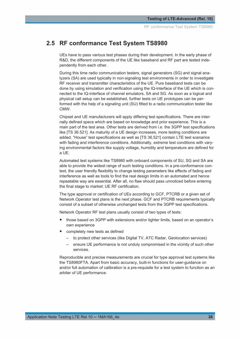
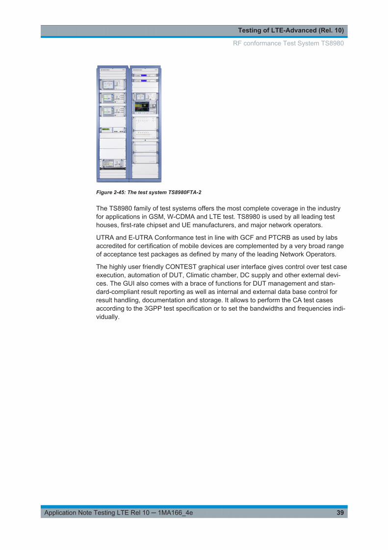
Figure 2-45: The test system TS8980FTA-2
The TS8980 family of test systems offers the most complete coverage in the industryfor applications in GSM, W-CDMA and LTE test. TS8980 is used by all leading testhouses, first-rate chipset and UE manufacturers, and major network operators.
UTRA and E-UTRA Conformance test in line with GCF and PTCRB as used by labsaccredited for certification of mobile devices are complemented by a very broad rangeof acceptance test packages as defined by many of the leading Network Operators.
The highly user friendly CONTEST graphical user interface gives control over test caseexecution, automation of DUT, Climatic chamber, DC supply and other external devi-ces. The GUI also comes with a brace of functions for DUT management and stan-dard-compliant result reporting as well as internal and external data base control forresult handling, documentation and storage. It allows to perform the CA test casesaccording to the 3GPP test specification or to set the bandwidths and frequencies indi-vidually.
RF conformance Test System TS8980

Testing of LTE-Advanced (Rel. 10)
40Application Note Testing LTE Rel 10 ─ 1MA166_4e
Figure 2-46: Contest testplan editor
Figure 2-47: CA band combinations in Contest
Margin Search routines and Performance Evaluation modes allow to evaluate theheadroom a DUT has vs certification-level PASS criteria or vs user-specified minimumvalues.
RF test for LTE and W-CDMA may be combined with RRM conformance for LTE / W-CDMA.
Test Case Packages
Available validated test case packages for LTE-A are
● CA-DL 2CC● e DL MIMO● eICIC
RF conformance Test System TS8980

Appendix
41Application Note Testing LTE Rel 10 ─ 1MA166_4e
3 Appendix
3.1 Literature
[1] Rohde & Schwarz: White Paper 1MA169 “LTE-Advanced Technology Introduction"
[2] Rohde & Schwarz: Application Note 1GP84 “Time Synchronous Signals with Multi-ple R&S®SMBV100A Vector Signal Generators”
[3] Rohde & Schwarz: Application Note 1MA198 “Measuring Multistandard Radio BaseStations”
[4] Rohde & Schwarz: Application Note 1MA143 “LTE Downlink MIMO Verification withR&S®SMU200A and R&S®FSQ”
[5] Rohde & Schwarz: Application Note 1GP97 “Higher Order MIMO Testing with theSMW200A”
3.2 Additional Information
Please send your comments and suggestions regarding this white paper to
3.3 Ordering information
Please visit the Rohde & Schwarz product websites at www.rohde-schwarz.com forordering information on the following Rohde & Schwarz products or contact your localRohde & Schwarz sales office for further assistance.
Vector Signal Generators
SMW200A vector signal generator
SGS100A vector signal generator
SGT100A vector signal generator
Signal and Spectrum Analyzer
FSW signal and spectrum analyzer
FSV signal and spectrum analyzer
FSVA signal and spectrum analyzer
FSVR signal and spectrum analyzer
Ordering information

Appendix
42Application Note Testing LTE Rel 10 ─ 1MA166_4e
Radio Communication Tester
CMW wideband radiocommunication tester
Test Systems
TS8980 Conformance test system
Ordering information

Rohde & Schwarz
43Application Note Testing LTE Rel 10 ─ 1MA166_4e
4 Rohde & SchwarzThe Rohde & Schwarz electronics group offers innovative solutions in the followingbusiness fields: test and measurement, broadcast and media, secure communications,cybersecurity, radiomonitoring and radiolocation. Founded more than 80 years ago,this independent company has an extensive sales and service network and is presentin more than 70 countries.
The electronics group is among the world market leaders in its established businessfields. The company is headquartered in Munich, Germany. It also has regional head-quarters in Singapore and Columbia, Maryland, USA, to manage its operations inthese regions.
Sustainable product design
● Environmental compatibility and eco-footprint● Energy efficiency and low emissions● Longevity and optimized total cost of ownership
Certified Quality Management
ISO 9001Certified Environmental Management
ISO 14001
Regional contact
● Europe, Africa, Middle East - [email protected] +49 89 4129 12345
● North America - [email protected] 1-888-TEST-RSA (1-888-837-8772)
● Latin America - [email protected] +1-410-910-7988
● Asia/Pacific - [email protected] +65 65 13 04 88
● China - [email protected] +86-800-810-8228 / +86-400-650-5896
Headquarters
Rohde & Schwarz GmbH & Co. KG
Mühldorfstraße 15 | D - 81671 München
+ 49 89 4129 - 0 | Fax + 49 89 4129 – 13777
www.rohde-schwarz.com
This application note and the supplied programs may only be used subject to the conditions of use set forthin the download area of the Rohde & Schwarz website.
R&S® is a registered trademark of Rohde & Schwarz GmbH & Co. KG. Trade names are trademarks of theowners.