testing and verification of dynamic power cables
TRANSCRIPT
No. 1 • April • 2012
Norwegian Marine Technology Research Institute
ISSN 0801-1818
Con
ten
ts Testing and verification of dynamic power cables
MARINTEK in the Arctic Management of ageing and life extension
1 2
Cont. on page 4
3
Testing and verification of dynamic power cables>> Research manager Frank Klæbo
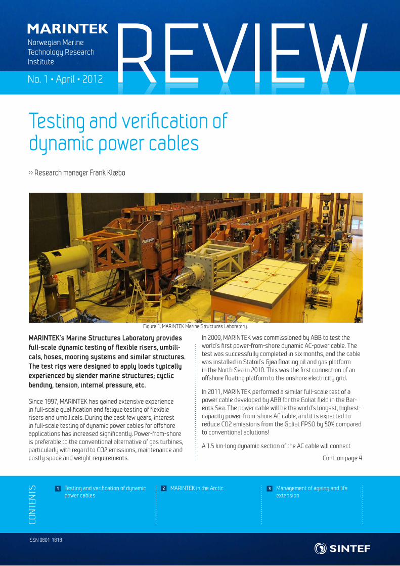
Figure 1. MARINTEK Marine Structures Laboratory.
MARINTEK’s Marine Structures Laboratory provides full-scale dynamic testing of flexible risers, umbili-cals, hoses, mooring systems and similar structures. The test rigs were designed to apply loads typically experienced by slender marine structures; cyclic bending, tension, internal pressure, etc.
Since 1997, MARINTEK has gained extensive experience in full-scale qualification and fatigue testing of flexible risers and umbilicals. During the past few years, interest in full-scale testing of dynamic power cables for offshore applications has increased significantly. Power-from-shore is preferable to the conventional alternative of gas turbines, particularly with regard to CO2 emissions, maintenance and costly space and weight requirements.
In 2009, MARINTEK was commissioned by ABB to test the world’s first power-from-shore dynamic AC-power cable. The test was successfully completed in six months, and the cable was installed in Statoil’s Gjøa floating oil and gas platform in the North Sea in 2010. This was the first connection of an offshore floating platform to the onshore electricity grid.
In 2011, MARINTEK performed a similar full-scale test of a power cable developed by ABB for the Goliat field in the Bar-ents Sea. The power cable will be the world’s longest, highest-capacity power-from-shore AC cable, and it is expected to reduce CO2 emissions from the Goliat FPSO by 50% compared to conventional solutions!
A 1.5 km-long dynamic section of the AC cable will connect
REVIEW
Communication challenges – MarSafe NorthAs the level of activity in the Arctic rises, focus is also sharp-ening on the safety and efficiency of marine operations in the region. Future support systems will be increasingly based on digital communication between installation vessels and shore. Safe and efficient communication in turn depends on adequate data capacity and reliability. Analyses performed by the MarSafe North and ArctiCOM projects have shown that current system performance is not sufficient to cover future demand and may be problematic even for certain current operations. Better knowledge of how atmospheric and iono-spheric factors influence Arctic communication capabilities are urgently needed, both to plan critical operations and to perform them safely. The recently launched MARENOR pro-ject will provide such information. Measurement campaigns on communication system performance in the Arctic will be run between 2012 and 2015.
2
Continued high oil and gas prices are fueling the interest for exploration of Arctic oil and gas resources. Norway has seen a significant increase in the interest for licenses for exploration areas in their part of the High North. 24 licenses were approved in April 2011 (12 in the Norwegian Sea and 12 in the Barents Sea). For the 22nd round 37 companies have nominated 228 blocks of which 181 were in the Barents Sea. The pristine Arctic region is vulnerable and the robustness of Arctic ecosystems is not fully known. MARINTEK will have a role to play to improve vessel and floating structures design and operational performance as well as in studies of infrastructure and logistic systems for Arctic oil and gas activities.
Sustainable arctic shipping and logistics Environmentally friendly and sustainable commercial ship-ping, offshore and marine operations face major challenges including distance to supply bases, lack of infrastructure, safety at sea and environmental preparedness for opera-tions in a harsh climate with extreme weather conditions in a biologically sensitive area. Meeting these challenges will require new multipurpose and modular vessels, new business models tailored to integrated shipping and field operations, transport solutions and logistics models as well as manage-ment systems for safe vessel operation. We also need better understanding of the impact of arctic operations on climate change and the environment, not to mention international regulation and transparent management of the Northeast Passage. For all the above reasons, MARINTEK is investigat-ing new logistics systems that also take the long distances and rough conditions into account.
Vessel design – Construction and intervention vessels for Arctic oil and gas (CIVARCTIC)Vessels operating on the Norwegian continental shelf in the High North must be capable of operating in open water and in first-year ice east of Svalbard. Winterisation is essential for year-round operation. MARINTEK has led the develop-ment of an Arctic intervention vessel designed to prolong the operational season for the installation and maintenance of subsea oil and gas installations in waters with seasonal ice. As a business case the vessel was designed for operation on fields off the coast of Northern Norway and east of Svalbard.
MARINTEK in the Arctic>> Senior Adviser Morten Henry Westvik >> Principal Research Engineer Tor Einar Berg >> Research Scientist Beate Kvamstad
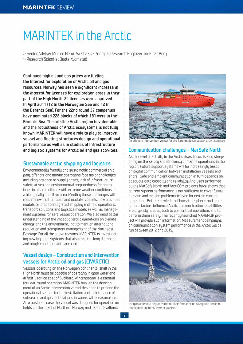
An offshore intervention vessel for the Barents Sea. (Illustration by STX OSV Design)
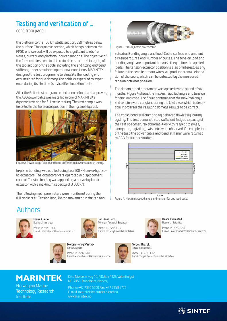
Icing on antennas degrades the total performance on navigation and com-munication systems. (Photo: Shutterstock)

No. 1 • April • 2012
3
Many oil and gas installations are approaching the end of their design life. Continued operation requires structured, strategic and holistic management of ageing structures, systems and components (SSC). MARINTEK has been working with the industry to develop a procedure for this, enabling operators to make decisions, in line with business objectives, for an extension of the life-time of their SSC.
Ageing refers to changes in the operational state of SSC. This operational state changes when the technological, organi-sational and external factors necessary for operation of the equipment, suffer from degradation, inefficiency or obsoles-cence. This raises two main questions:
1. Is my equipment subject to ageing or will it suffer from ageing within the operational time horizon?
2. If so, what should I do to ensure optimum operation over the operational horizon?
In cooperation with the petroleum industry, MARINTEK has developed a toolbox to identify ageing, estimate remaining useful life and support decision-making for ageing equipment. This has all been integrated into a single procedure, enabling operators to make optimum safety, cost and regularity deci-sions for ageing equipment. The functionality and usability of the procedure has been tested, and it is considered to have great potential for management of ageing and life extension.
To operate equipment over a future operating horizon (i.e. life extension period), several alternative strategies exist, as illustrated in figure 1.
Consider a system that has operated for some time and that has been monitored in order to follow the ageing condition. Ageing is not a binary process, but at some point in time we can say that the system has ageing issues that need atten-tion and where actions should be evaluated. In this case, three main alternative courses of action exist:
1. Continue to overhaul and repair the existing system.
2. Replace the existing system with a new one.
3. Modify the existing system.
Based on technical evaluations and estimates of remain-ing useful life, different decision paths within the above 3 alternatives can be identified for the system and allocated to different stages of the life-extension period. Infeasible decision alternatives and paths can be eliminated on the basis of specific screening criteria. The remaining paths can be quantified according to business objectives and optimum decisions at different points in time can be identified.
The toolbox for ageing management and life extension, including the corresponding integrating procedure, is flexible and practical. It can be used for smaller or larger projects or challenges, and provides a high degree of traceability and vis-ibility in relation to decision making. It is flexible in its ability to use expert judgments in cases where data are limited, and it integrates several different disciplines in order to create shared situational awareness which is a prerequisite for ageing management. MARINTEK seek to further enhance it by automating the process and making it more user-friendly and user-independent. This will enable operators to use the toolbox even more efficiently, saving resources, and perform-ing the assessments as part of daily work.
This structured, strategic and holistic tool for the management of ageing equipment has great potential for raising safety levels and improving the economics of petroleum industry assets.
Management of ageing and life extension>> Research Scientist Torgeir Brurok
Ageingidentified
Modify
Replace
Overhaul
Past Now Future
Modify
Replace
Overhaul
?
?
?
?
?
Safety, cost, regularity
Operating horizonFigure 1. Alternative strategies for ageing structures, systems and compo-nents.
Figure 2. Shared situational awareness and decision making for ageing structures, systems and components.
NORWEGIAN MARINE TECHNOLOGY RESEARCH InstItUte
Otto Nielsens veg 10, P.O.Box 4125 Valentinlyst NO-7450 Trondheim, Norway
Phone: +47 7359 5500 Fax: +47 7359 5776E-mail: [email protected] www.marintek.no
Norwegian Marine Technology Research Institute
Authors
Morten Henry WestvikSenior Adviser
Phone: +47 9247 8788E-mail: [email protected]
Torgeir Brurok Research scientist
Phone: +47 9716 3582E-mail: [email protected]
Tor Einar BergPrincipal Research Engineer
Phone: +47 9265 9975E-mail: [email protected]
Beate KvamstadResearch Scientist
Phone: +47 9222 2240E-mail: [email protected]
Frank KlæboResearch manager
Phone: +47 4737 8649E-mail: [email protected]
the platform to the 105 km static section, 350 metres below the surface. The dynamic section, which hangs between the FPSO and seabed, will be exposed to significant loads from waves, current and platform-induced motions. The objective of the full-scale test was to determine the structural integrity of the top section of the cable, including the end fitting and bend stiffener, under simulated operational conditions. MARINTEK designed the test programme to simulate the loading and accumulated fatigue damage the cable is expected to experi-ence during its life time (service life simulation test).
After the Goliat test programme had been defined and approved, the ABB power cable was installed in one of MARINTEK’s dynamic test rigs for full-scale testing. The test sample was installed in the horizontal position in the rig; see Figure 2.
In-plane bending was applied using two 500 kN servo-hydrau-lic actuators. The actuators were operated in displacement control. Tension loading was applied by a servo-hydraulic actuator with a maximum capacity of 3 000 kN.
The following main parameters were monitored during the full-scale test; Tension load, Piston movement in the tension
actuator, Bending angle and load, Cable surface and ambient air temperatures and Number of cycles. The tension load and bending angle are important because they define the applied loads. The tension actuator position is also of interest, as any failure in the tensile armour wires will produce a small elonga-tion of the cable, which can be detected by the measured tension actuator position.
The dynamic load programme was applied over a period of six months. Figure 4 shows the max/min applied angle and tension for one load case. The figure confirms that the max/min angle and tension were constant during the load case, which is desir-able in order for the resulting damage results to be correct.
The cable, bend stiffener and rig behaved flawlessly during cycling. The test demonstrated sufficient fatigue capacity of the test specimen. No abnormalities with respect to noise, elongation, pigtailing, twist, etc. were observed. On completion of the test, the power cable and bend stiffener were returned to ABB for further studies.
Figure 3. ABB dynamic power cable
Figure 2. Power cable (black) and bend stiffener (yellow) installed in the rig.
Figure 4. Max/min applied angle and tension for one load case.
Testing and verification of ... cont. from page 1