tester ut61english
TRANSCRIPT

7/15/2019 Tester Ut61english
http://slidepdf.com/reader/full/tester-ut61english 1/68
Table of Contents
4
5
6
79
10
11
12
13
15
1518
21
24
26
29
31
33
Title PageOverview
Unpacking Inspection
Safety Information
Rules For Safe Operation
International Electrical Symbols
The Meter Structure
Rotary Switch
Functional Buttons
Display Symbols
Measurement Operation
A.DC/AC Voltage MeasurementB.DC/AC Current Measurement
C.Measuring Resistance
D.Testing for Continuity
E.Testing Diodes
F.Capacitance Measurement
G.Frequency Measurement
H.Temperature Measurement
Model UT61A/61B/61C/61D/61E: OPERATING MANUAL
1

7/15/2019 Tester Ut61english
http://slidepdf.com/reader/full/tester-ut61english 2/68
35
37
38
39
39
39
40
40
41
41
41
4243
44
46
49
52
55
Title Page
I.Transistor hFE Measurement
J.EF Function
Operation of Hold Mode
RANGE Button
MAX MIN ButtonPEAK Button
Data Outputting
The Use of Relative Value Mode
The BLUE Button
Turning on the Display Backlight
Sleep Mode
General Specifications Accuracy Specifications
A.DC Voltage
B.AC Voltage
C.DC Current
D.AC Current
E.Resistance
Model UT61A/61B/61C/61D/61E: OPERATING MANUAL
2

7/15/2019 Tester Ut61english
http://slidepdf.com/reader/full/tester-ut61english 3/68
Title Page
57
59
60
60
61
62
62
62
63
65
67
F.Capacitance
G.Frequency
H.Diode Test
I.Continuity Test
J.Temperature
K.Transistor hFE
Maintenance
A.General Service
B.Replacing the Battery
C.Replacing the Fuses
USB and RS232C Serial Port
Model UT61A/61B/61C/61D/61E: OPERATING MANUAL
3

7/15/2019 Tester Ut61english
http://slidepdf.com/reader/full/tester-ut61english 4/68
This Operating Manual covers information on safety and cautions. Please read the
relevant information carefully and observe all the Warnings and Notes strictly.
Warning
Model UT61A/61B/61C/61D/61E: OPERATING MANUAL
4

7/15/2019 Tester Ut61english
http://slidepdf.com/reader/full/tester-ut61english 5/68
Except where noted, the descriptions and instructions in this Operating Manual apply
to all Model UT61A/UT61B/UT61C/UT61D/UT61E.
Unpacking InspectionOpen the package case and take out the Meter. Check the following items carefully
to see any missing or damaged part:
Description
Operating Manual
Test Lead
Point Contact K type Temperature Probe (UT61B and UT61C only)
UT61 Multi-Purpose Socket9V Battery (NEDA1604, 6F22 or 0006P) (installed inside the Meter)
RS232C Interface Cable(except UT61A)
USB Interface Cable (Optional at extra cost) (except UT61A)
Installation Guide & Computer Interface Software (CD-ROM) (Come
along with the RS232C or USB Interface Cable) (except UT61A)
Item
1
2
3
45
6
7
8
Qty
1 piece
1 pair
1 piece
1 piece1 piece
1 piece
1 piece
1 piece
Model UT61A/61B/61C/61D/61E: OPERATING MANUAL
5

7/15/2019 Tester Ut61english
http://slidepdf.com/reader/full/tester-ut61english 6/68
In the event you find any missing or damage, please contact your dealer immediately.
Safety Information
This Meter complies with the standards IEC61010: in pollution degree 2, overvoltage
category (CAT. III 1000V, CAT. IV 600V) and double insulation.
CAT III: Distribution level, fixed installation, with smaller transient overvoltages thanCAT. IV.
CAT IV: Primary supply level, overhead lines, cable systems etc.
Use the Meter only as specified in this operating manual, otherwise the protection
provided by the Meter may be impaired.
In this manual, a Warning identifies conditions and actions that pose hazards to the
user, or may damage the Meter or the equipment under test.
A Note identifies the information that user should pay attention on.
International electrical symbols used on the Meter and in this Operating Manual are
explained on page9.
Model UT61A/61B/61C/61D/61E: OPERATING MANUAL
6
7/15/2019 Tester Ut61english
http://slidepdf.com/reader/full/tester-ut61english 7/68
Rules For Safe Operation
Warning
To avoid possible electric shock or personal injury, and to avoid possible
damage to the Meter or to the equipment under test, adhere to the following
rules:
l Before using the Meter inspect the case. Do not use the Meter if it isdamaged or the case (or part of the case) is removed. Look for cracks or missing plastic. Pay attention to the insulation around the connectors.
l Inspect the test leads for damaged insulation or exposed metal. Checkthe test leads for continuity. Replace damaged test leads with identicalmodel number or electrical specifications before using the Meter.
l Do not apply more than the rated voltage, as marked on the Meter, betweenthe terminals or between any terminal and grounding.
l The rotary switch should be placed in the right position and no anychangeover of range shall be made during measurement is conducted toprevent damage of the Meter.
l When the Meter working at an effective voltage over 60V in DC or 30Vrms in AC, special care should be taken for there is danger of electricshock.
Model UT61A/61B/61C/61D/61E: OPERATING MANUAL
7

7/15/2019 Tester Ut61english
http://slidepdf.com/reader/full/tester-ut61english 8/68
l Do not use or store the Meter in an environment of high temperature,humidity, explosive, inflammable and strong magnetic field. The performanceof the Meter may deteriorate after dampened.
l When using the test leads, keep your fingers behind the finger guards.l Disconnect circuit power and discharge all high-voltage capacitors before
testing resistance, continuity and diodes.
l Before measuring current, check the Meterís fuses and turn off the currentto be tested before connecting the Meter to the circuit. After connectingthe circuit reliably, turn the current to be tested on.
l Replace the battery as soon as the battery indicator appears. With alow battery, the Meter might produce false readings that can lead to electric
shock and personal injury.l When servicing the Meter, use only the same model number or identical
electrical specifications replacement parts.l The internal circuit of the Meter shall not be altered at will to avoid damage
of the Meter and any accident.l Soft cloth and mild detergent should be used to clean the surface of the
Meter when servicing. No abrasive and solvent should be used to preventthe surface of the Meter from corrosion, damage and accident.
l The Meter is suitable for indoor use.
Model UT61A/61B/61C/61D/61E: OPERATING MANUAL
8

7/15/2019 Tester Ut61english
http://slidepdf.com/reader/full/tester-ut61english 9/68
l Turn the Meter off when it is not in use and take out the battery when not
using for a long time.
l Constantly check the battery as it may leak when it has been using for
some time, replace the battery as soon as leaking appears. A leaking
battery will damage the Meter.
International Electrical Symbols
AC or DC
Double Insulated
Warning. Refer to the Operating
Manual
Grounding
Deficiency of Built-In Battery
Conforms to Standards of
European Union
Model UT61A/61B/61C/61D/61E: OPERATING MANUAL
9

7/15/2019 Tester Ut61english
http://slidepdf.com/reader/full/tester-ut61english 10/68
The Meter Structure (see figure 1)
LCD Display
Functional Buttons
Blue button
Rotary Switch
Input Terminal:
figure 1
1
2
3
4
5
Model UT61A/61B/61C/61D/61E: OPERATING MANUAL
10

7/15/2019 Tester Ut61english
http://slidepdf.com/reader/full/tester-ut61english 11/68
Rotary SwitchBelow table indicated for information about the rotary switch positions.
AC and DC Voltage Measurement
AC Voltage Measurement (UT61D only)
DC Voltage Measurement (UT61D only)
Resistance Measurement
Diode Test
Continuity Test
Capacitance Test
Frequency and Duty Cycle Test
Temperature in Celsius (UT61B and UT61C only)
Temperature in Fahrenheit (UT61B and UT61C only)
Transistor (UT61A only)
DCA and ACA Measurement
DCmA and ACmA Measurement
10A DC and AC Measurement
Sensor Test (UT61A only)
Power off OFF
mV
Model UT61A/61B/61C/61D/61E: OPERATING MANUAL
11

7/15/2019 Tester Ut61english
http://slidepdf.com/reader/full/tester-ut61english 12/68
Functional ButtonsBelow table indicated for information about the functional button operations.
Press to select the maximum and minimum value.
Operation PerformedPress and hold for 2 serconds to turn the display backlight on or off.Press to enter or exit data hold mode.Press to select the alternate feature
Press RANGE to enter the manual ranging mode;the Meter beeps.
Press RANGE to step through the ranges available for the
selected function; the Meter beeps.
Press and hold RANGE for 2 seconds to return to autoranging;
the Meter beeps
Press again to exit REL mode
For Model UT61C, UT61C and
Press and hold for over 2 seconds to enter or exit RS232C or
USB mode.
Press to enter REL mode.
Button
HoldBLUE Button
RANGE
REL
PEAK (UT61E only)
"CAL" means the meter enter self-calibration mode.
Model UT61A/61B/61C/61D/61E: OPERATING MANUAL
12

7/15/2019 Tester Ut61english
http://slidepdf.com/reader/full/tester-ut61english 13/68
Display Symbols
Meaning
Data hold is active.
Sleep Mode indicator
Indicates negative reading.
Indicator for AC measurement
Indicator for DC measurement
The Meter is in the auto range mode in which the Meter automaticallyselects the range with the best resolution.
Indicator for manual ranging mode.
The input value is too large for the selected range.
Transistor testing indicator
Test of diode
The continuity buzzer is on.Maximum and Minimum reading.
Data output is in progress
The battery is low.Warning: To avoid false readings, which could lead to
possible electric shock or personal injury, replace the batteryas soon as the battery indicator appears.
Sensor test is in progress
No
12345
6
7
8
910
11121314
15
Symbol
Model UT61A/61B/61C/61D/61E: OPERATING MANUAL
13

7/15/2019 Tester Ut61english
http://slidepdf.com/reader/full/tester-ut61english 14/68
No
The REL is on to display the stored value minus the present value.
: Ohm. The unit of resistance.
k : kilohm. 1 x 10³ or 1000 ohms.
M : Megaohm. 1 x 10⁶ or 1,000,000 ohms.
V: Volts. The unit of voltage.mV: Millivolt. 1 x 10⁻³ or 0.001 volts.
A: Amperes (amps). The unit of current.
mA: Milliamp. 1 x 10⁻³ or 0.001 amperes
µA : Microamp. 1x 10⁻⁶ or 0.000001 amperes
F: Farad. The unit of capacitance.
µF : Microfarad. 1 x 10⁻⁶ or 0.000001 farads.
nF : Nanofarad. 1 x 10⁻⁹
or 0.000000001 farads.: Centigrade. The unit of temperature.
: Fahrenheit. The unit of temperature.
Hz: Hertz. The unit of frequency in cycles/second.
kHz: Kilohertz. 1 x 10³ or 1,000 hertz.
MHz: Megahertz. 1 x 10⁶ or1,000,000 hertz.
The unit of transistor
16
17
Symbol Meaning
Model UT61A/61B/61C/61D/61E: OPERATING MANUAL
14

7/15/2019 Tester Ut61english
http://slidepdf.com/reader/full/tester-ut61english 15/68
Measurement Operation
A. DC/AC Voltage Measurement (See figure 2)
figure 2
Model UT61A/61B/61C/61D/61E: OPERATING MANUAL
15

7/15/2019 Tester Ut61english
http://slidepdf.com/reader/full/tester-ut61english 16/68
WarningTo avoid harms to you or damages to the Meter from electric shock, please donot attempt to measure voltages higher than 1000V although readings may beobtained.
When measuring high voltage, take extra care to avoid electric shock.
1. Insert the red test lead into the V terminal and the black test lead into the COMterminal.2. Set the rotary switch to V; DC measurement is default or press BLUE button to
switch between DC and AC measurement mode.3. Connect the test leads across with the object being measured. The measured
value shows on the display. UT61A, UT61B and UT61C: display effective value of sine wave (mean value
response).
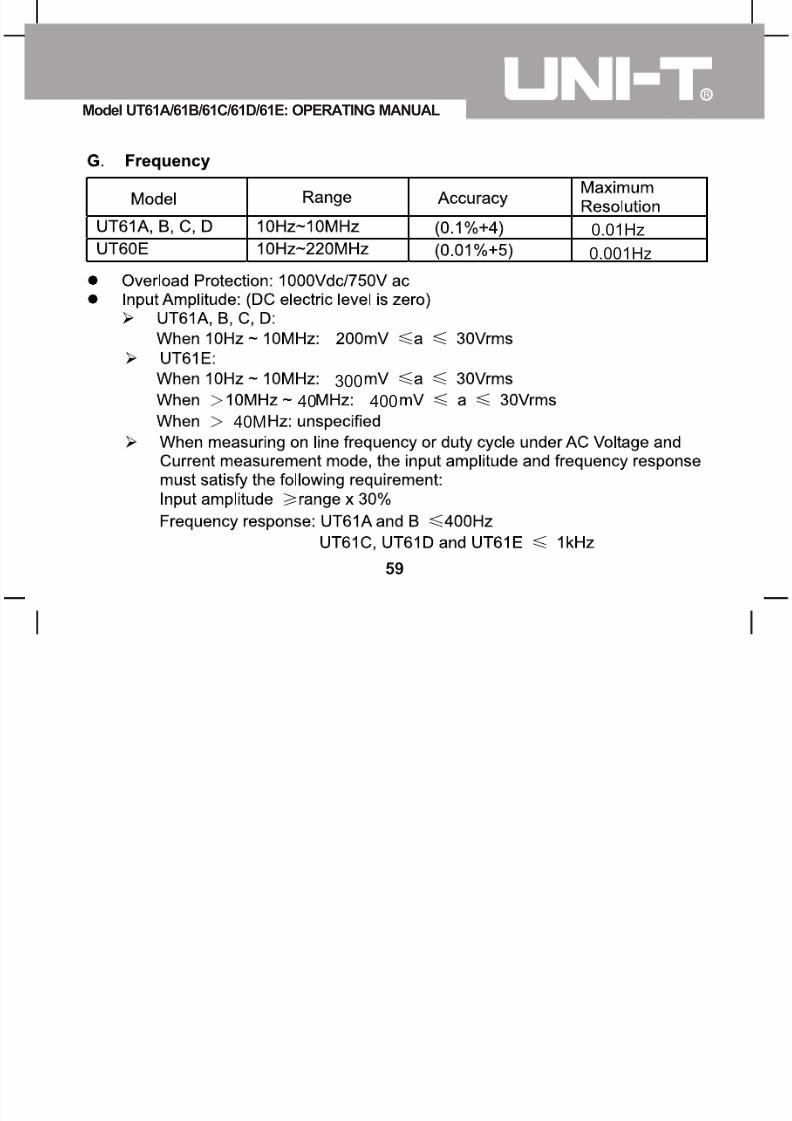
UT61D and UT61E: display true rms value.4. Press Hz% to obtain the frequency and duty cycle value. Input Amplitude: (DC electric level is zero) Input Amplitude: range 30% Frequency respouse:UT61A and B 400Hz
UT61C,UT61D and UT61E 1KHz
Model UT61A/61B/61C/61D/61E: OPERATING MANUAL
16

7/15/2019 Tester Ut61english
http://slidepdf.com/reader/full/tester-ut61english 17/68
Note
l In each range, the Meter has an input impedance of 10M except mV range
which input impedance is 3000M . This loading effect can cause measurement
errors in high impedance circuits. If the circuit impedance is less than or equal
to 10k , the error is negligible (0.1% or less).
l For UT61A and UT61B:When measuring mV, you must press RANGE manually
to enter mV range.l When voltage measurement has been completed, disconnect the connection
between the testing leads and the circuit under test, and remove the testing leads
away from the input terminals of the Meter.
Model UT61A/61B/61C/61D/61E: OPERATING MANUAL
17

7/15/2019 Tester Ut61english
http://slidepdf.com/reader/full/tester-ut61english 18/68
B. DC/AC Current Measurement (See figure 3)
figure 3
A
Model UT61A/61B/61C/61D/61E: OPERATING MANUAL
18

7/15/2019 Tester Ut61english
http://slidepdf.com/reader/full/tester-ut61english 19/68
WarningBefore connecting the Meter to the return circuit to be tested, cut off the currentof the return circuit.
If the fuse burns out during measurement, the Meter may be damaged or theoperator himself may be hurt.
Use proper terminals, function, and range for the measurement.
When the testing leads are connected to the current terminals, do not parallelthem across any circuit.
To measure current, do the following:
1. Insert the red test lead into the mA or A input terminal and the black test lead
into the COM terminal.2. Set the rotary switch to A, mA, or A.
3. The Meter defaults to DC current measurement mode. To toggle between DC
and AC current measurement function, press BLUE button.
4. Connect the test lead in serial to the return circuit to be tested. The measured
value shows on the display.
Model UT61A/61B/61C/61D/61E: OPERATING MANUAL
19

7/15/2019 Tester Ut61english
http://slidepdf.com/reader/full/tester-ut61english 20/68
UT61A, UT61B and UT61C: display effective value of sine wave (meanvalue response).UT61D and UT61E: display true rms value.
5. Press Hz% to obtain the frequency and duty cycle value. Input Amplitude: (DC electric level is zero) Input Amplitude: range 30%
Frequency response:UT61A and B 400HzUT61C , UT61D andUT61E 1KHz
Notel
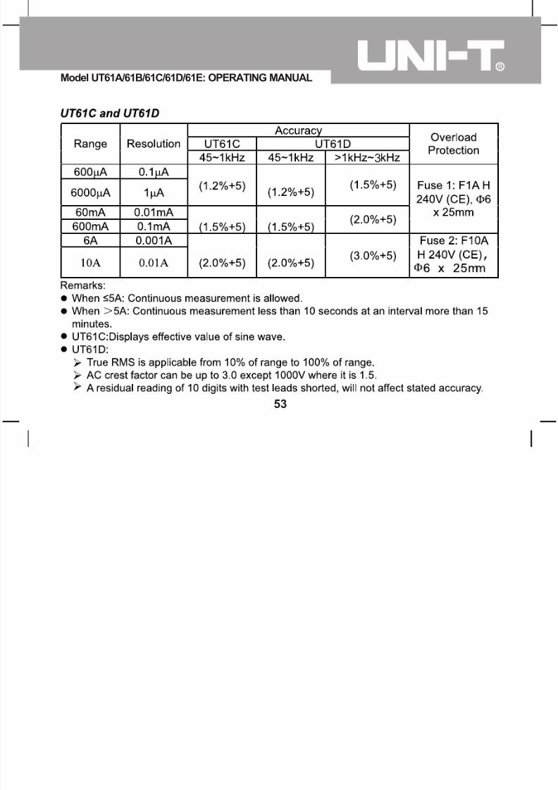
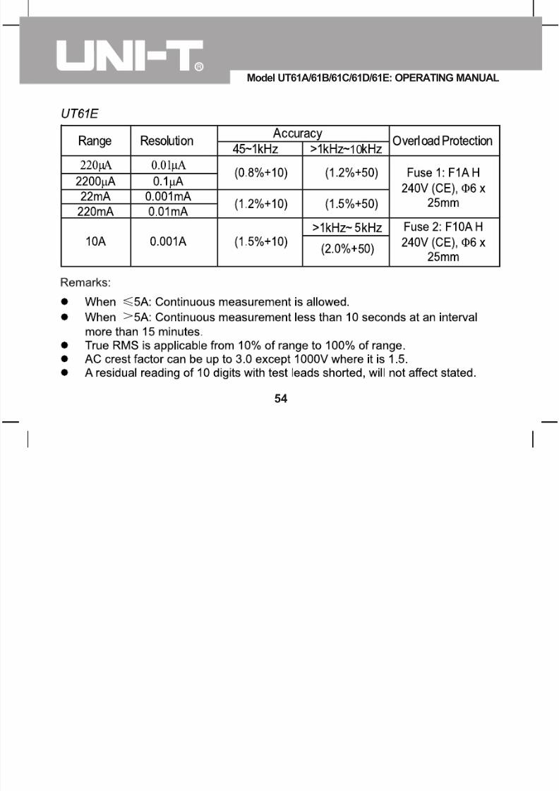
If the value of current to be measured is unknown, use the maximum measurementposition, and reduce the range step by step until a satisfactory reading is obtained.l For safety sake, each measurement time for >5A current should be less than
10 seconds and the interval time between 2 measurements should be greater than 15 minutes.
l When current measurement has been completed, disconnect the connectionbetween the testing leads and the circuit under test, and remove the testing leadsaway from the input terminals of the Meter.
Model UT61A/61B/61C/61D/61E: OPERATING MANUAL
20

7/15/2019 Tester Ut61english
http://slidepdf.com/reader/full/tester-ut61english 21/68
C. Measuring Resistance (See figure 4)
figure 4
Model UT61A/61B/61C/61D/61E: OPERATING MANUAL
21
7/15/2019 Tester Ut61english
http://slidepdf.com/reader/full/tester-ut61english 22/68
Warning
To avoid damages to the Meter or to the devices under test, disconnect circuit
power and discharge all the high-voltage capacitors before measuring resistance.
To avoid harm to yourself, do not input higher than DC 60V or AC 30V voltages.
To measure resistance, connect the Meter as follows:
1. Insert the red test lead into the terminal and the black test lead into the COM
terminal.
2. Set the rotary switch to resistance measurement ( ) is default or press BLUE
button to select measurement mode.
3. Connect the test leads across with the object being measured. If there is lead on
the resistor or SMT resistor, it is more convenience to use the included multi-purpose socket to carry out testing.The measured value shows on the display.
Model UT61A/61B/61C/61D/61E: OPERATING MANUAL
22

7/15/2019 Tester Ut61english
http://slidepdf.com/reader/full/tester-ut61english 23/68
Model UT61A/61B/61C/61D/61E: OPERATING MANUAL
23

7/15/2019 Tester Ut61english
http://slidepdf.com/reader/full/tester-ut61english 24/68
D. Testing for Continuity (See figure 5)
figure 5
Model UT61A/61B/61C/61D/61E: OPERATING MANUAL
24

7/15/2019 Tester Ut61english
http://slidepdf.com/reader/full/tester-ut61english 25/68
WarningTo avoid damages to the Meter or to the devices under test, disconnect circuitpower and discharge all the high-voltage capacitors before testing for continuity.
To avoid harm to yourself, do not input higher than DC 60V or AC 30V voltages.
To test for continuity, connect the Meter as below:1. Insert the red test lead into the terminal and the black test lead into the COM
terminal.2. Set the rotary switch to and press BLUE button to select measurement mode.3. The buzzer sounds continuously if the resistor to be tested is <10 .
The buzzer does not sound if the resistor to be tested is >35
Note
l UT61A, UT61B, UT61C and UT61D: open circuit voltage is around 0.45VUT61E: open circuit voltage is around -1.2V
l When continuity testing has been completed, disconnect the connectionbetween
the testing leads and the circuit under test, and remove the testing leads awayfrom the input terminals of the Meter.
Model UT61A/61B/61C/61D/61E: OPERATING MANUAL
25

7/15/2019 Tester Ut61english
http://slidepdf.com/reader/full/tester-ut61english 26/68
E. Testing Diodes (See figure 6)
figure 6
Model UT61A/61B/61C/61D/61E: OPERATING MANUAL
26

7/15/2019 Tester Ut61english
http://slidepdf.com/reader/full/tester-ut61english 27/68
Model UT61A/61B/61C/61D/61E: OPERATING MANUAL
27

7/15/2019 Tester Ut61english
http://slidepdf.com/reader/full/tester-ut61english 28/68
l Connect the test leads to the proper terminals as said above to avoid error display. The LCD will display OL indicating diode being tested is open or polarityis reversed. The unit of diode is Volt (V), displaying the forward voltage dropreadings.
l When diode testing has been completed, disconnect the connection betweenthe testing leads and the circuit under test, and remove the testing leads away
from the input terminals of the Meter.
Model UT61A/61B/61C/61D/61E: OPERATING MANUAL
28

7/15/2019 Tester Ut61english
http://slidepdf.com/reader/full/tester-ut61english 29/68
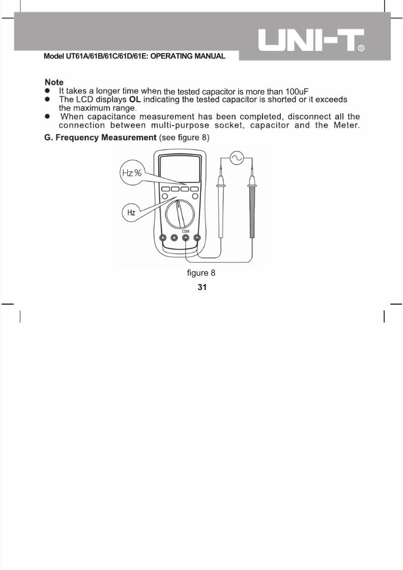
F. Capacitance Measurement (See figure 7)
figure 7
Model UT61A/61B/61C/61D/61E: OPERATING MANUAL
29

7/15/2019 Tester Ut61english
http://slidepdf.com/reader/full/tester-ut61english 30/68
WarningTo avoid damage to the Meter or to the equipment under test, disconnect circuitpower and discharge all high-voltage capacitors before measuring capacitance.Use the DC Voltage function to confirm that the capacitor is discharged.
To measure capacitance, connect the Meter as follows:
1. Insert the red test lead into the terminal and the black test lead into the COM
terminal.2. Set the rotary switch to and press BLUE button to select nF measurement mode. l At that time, the Meter will display a fixed value as below which is the Meter
internal fixed distributed capacitance value. To ensure accuracy whenmeasuring a small value of capacitance, the tested value must subtract thisvalue, REL mode can help on that.
UT61A, UT61B, UT61C, UT61D and UT61E: around 10nF
UT61E: around 50PFl For more convenience, use the included multi-purpose socket for measuring
capacitor with leads or SMT capacitor. Insert the capacitor to be tested intothe corresponding "+" and "-" jack of the multi-purpose socket. This methodis more stable and correct for small value of capacitance testing.
3. Connect the test leads across with the object being measured.The measured value shows on the display.
Model UT61A/61B/61C/61D/61E: OPERATING MANUAL
30
7/15/2019 Tester Ut61english
http://slidepdf.com/reader/full/tester-ut61english 31/68
figure 8
n the tested capacitor is more than 100uF
Model UT61A/61B/61C/61D/61E: OPERATING MANUAL
31

7/15/2019 Tester Ut61english
http://slidepdf.com/reader/full/tester-ut61english 32/68
300
For UT61E:Measuring Audio frequency,if the input voltage is more than 15 volt.the meter will simulate the sound in same frequency.
40MHz:unspecified44
Model UT61A/61B/61C/61D/61E: OPERATING MANUAL
32

7/15/2019 Tester Ut61english
http://slidepdf.com/reader/full/tester-ut61english 33/68
l When frequency measurement has been completed, disconnect the connection
between the testing leads and the circuit under test, and remove the testing leads
away from the input terminals of the Meter.
H. Temperature Measurement (UT61B and UT61C only) (See figure 9)
figure 9)
Model UT61A/61B/61C/61D/61E: OPERATING MANUAL
33

7/15/2019 Tester Ut61english
http://slidepdf.com/reader/full/tester-ut61english 34/68
WarningTo avoid harm to yourself, do not input higher than DC 60V or AC 30V voltages.
To measure temperature, connect the Meter as follows:
1. Set the rotary switch to .
2. Insert the temperature probe into the input terminal as shown on the figure 9.
3. Place the temperature probe to the object being measured.After few seconds, the measured value shows on the display.
4. Press BLUE button to toggle between and temperature.
Notel To avoid measurement error especially low temperature measurement, the
operating temperature must not exceed 18 ~ 28 .
lWhen temperature measurement has been completed, disconnect the connectionbetween the temperature probe and the object being measured, and remove the
temperature probe away from the input terminals of the Meter.
Model UT61A/61B/61C/61D/61E: OPERATING MANUAL
34

7/15/2019 Tester Ut61english
http://slidepdf.com/reader/full/tester-ut61english 35/68
I. Transistor hFE Measurement (UT61A only) (See figure 10)
figure 10
Model UT61A/61B/61C/61D/61E: OPERATING MANUAL
35

7/15/2019 Tester Ut61english
http://slidepdf.com/reader/full/tester-ut61english 36/68
1. Set the rotary switch to hFE.
2. Insert the multi-purpose socket into the input terminal as shown on figure 10.
3. Insert the transistor to be tested into the corresponding multi-purpose socket jacks.
4. The LCD display hFE nearest value
Note
l When transistor measurement has been completed, disconnect all the connection
between multi-purpose socket, transistor and the Meter.
Model UT61A/61B/61C/61D/61E: OPERATING MANUAL
36

7/15/2019 Tester Ut61english
http://slidepdf.com/reader/full/tester-ut61english 37/68
J. EF Function (UT61A only) (See figure 11)
figure 11
Model UT61A/61B/61C/61D/61E: OPERATING MANUAL
37

7/15/2019 Tester Ut61english
http://slidepdf.com/reader/full/tester-ut61english 38/68
To use EF function, connect the Meter as follows:
1. Set the rotary switch to EF and remove the test lead from the input terminals.
2. Place the housing front part with marking towards the object being measured.
3. There will be three types of displays:
ÿ LCD displays different size of digits to represent the strength of detected
signal.
ÿ When the LCD displays OL, the buzzer beeps and the red LED blinks.
Operation of Hold Mode
Warning
To avoid possibility of electric shock, do not use Hold mode to determine if circuitsare without power. The Hold mode will not capture unstable or noisy readings.
The Hold mode is applicable to all measurement functions.
l Press HOLD to enter Hold mode; the Meter beeps.
l Press HOLD again to exit Hold mode; the Meter beeps.
l In Hold mode, is displayed.
Model UT61A/61B/61C/61D/61E: OPERATING MANUAL
38

7/15/2019 Tester Ut61english
http://slidepdf.com/reader/full/tester-ut61english 39/68
RANGE buttonl Press RANGE to enter the manual ranging mode; the Meter beeps.l Press RANGE to step through the ranges available for the selected function;
the Meter beeps.l Press and hold RANGE for over 2 seconds to return to autoranging; the Meter
beeps.
MAX MIN button (UT61A, UT61B, UT61C and UT61D only)
l Press MAX MIN to start recording of maximum and minimum values. Stepsthe display through high (MAX) and low (MIN) readings. The Meter entersmanual ranging mode after pressing MAX MIN button.
l Press and hold MAX MIN for over 2 seconds to exit MAX MIN mode and returnto the present measurement range.
PEAK Hold (UT61E only)l Under voltage and current measurement mode, press PEAK button to enter
manual ranging mode and start recording of Pmax and Pmin values. The LCDdisplays MANU/Pmax.
l Press PEAK again to display MANU/Pmin.l Press PEAK to step the display through Peak Max and Peak Min readings.l Press and hold PEAK for over 2 seconds to exit Peak mode, the LCD displays
the present measurement values.l Don't press the "PEAK" Key.If the meter have entered "CAL" mode.
Model UT61A/61B/61C/61D/61E: OPERATING MANUAL
39

7/15/2019 Tester Ut61english
http://slidepdf.com/reader/full/tester-ut61english 40/68
For UT61E,Auto entering Data outputting mode.
Model UT61A/61B/61C/61D/61E: OPERATING MANUAL
40

7/15/2019 Tester Ut61english
http://slidepdf.com/reader/full/tester-ut61english 41/68
Model UT61A/61B/61C/61D/61E: OPERATING MANUAL
41

7/15/2019 Tester Ut61english
http://slidepdf.com/reader/full/tester-ut61english 42/68
General Specifications
l Maximum Voltage between any Terminals and Grounding:
Refer to the different ranges input protection voltage..
l Fused Protection for AmA Input Terminal:1A H 240V 6x25mm.
l Fused Protection for 10A Input Terminal:10A H 240V 6x25mm.
l Display
UT61A and UT61B:Maximum reading 4000 (frequency 9999), analogue
bar graph 41 segments
UT61C and UT61D:Maximum reading 6000 (frequency 9999), analogue
bar graph 61 segments.
UT61E:Maximum reading 22000, analogue bar graph 46 segments
l Measurement Speed: Updates 2~3 times/second.
l Range: Auto or Manuall Polarity Display: Autol Overload indication: Display OLl Battery Deficiency: Display
Model UT61A/61B/61C/61D/61E: OPERATING MANUAL
42

7/15/2019 Tester Ut61english
http://slidepdf.com/reader/full/tester-ut61english 43/68
Model UT61A/61B/61C/61D/61E: OPERATING MANUAL
43

7/15/2019 Tester Ut61english
http://slidepdf.com/reader/full/tester-ut61english 44/68
Model UT61A/61B/61C/61D/61E: OPERATING MANUAL
44

7/15/2019 Tester Ut61english
http://slidepdf.com/reader/full/tester-ut61english 45/68
(0.8%+3)
Model UT61A/61B/61C/61D/61E: OPERATING MANUAL
45

7/15/2019 Tester Ut61english
http://slidepdf.com/reader/full/tester-ut61english 46/68
Model UT61A/61B/61C/61D/61E: OPERATING MANUAL
46

7/15/2019 Tester Ut61english
http://slidepdf.com/reader/full/tester-ut61english 47/68
3
Model UT61A/61B/61C/61D/61E: OPERATING MANUAL
47

7/15/2019 Tester Ut61english
http://slidepdf.com/reader/full/tester-ut61english 48/68
Model UT61A/61B/61C/61D/61E: OPERATING MANUAL
48

7/15/2019 Tester Ut61english
http://slidepdf.com/reader/full/tester-ut61english 49/68
Model UT61A/61B/61C/61D/61E: OPERATING MANUAL
49

7/15/2019 Tester Ut61english
http://slidepdf.com/reader/full/tester-ut61english 50/68
0
Model UT61A/61B/61C/61D/61E: OPERATING MANUAL
50

7/15/2019 Tester Ut61english
http://slidepdf.com/reader/full/tester-ut61english 51/68
Model UT61A/61B/61C/61D/61E: OPERATING MANUAL
51

7/15/2019 Tester Ut61english
http://slidepdf.com/reader/full/tester-ut61english 52/68
Model UT61A/61B/61C/61D/61E: OPERATING MANUAL
52
7/15/2019 Tester Ut61english
http://slidepdf.com/reader/full/tester-ut61english 53/68
3
Model UT61A/61B/61C/61D/61E: OPERATING MANUAL
53
7/15/2019 Tester Ut61english
http://slidepdf.com/reader/full/tester-ut61english 54/68
10
Model UT61A/61B/61C/61D/61E: OPERATING MANUAL
54

7/15/2019 Tester Ut61english
http://slidepdf.com/reader/full/tester-ut61english 55/68
Model UT61A/61B/61C/61D/61E: OPERATING MANUAL
55

7/15/2019 Tester Ut61english
http://slidepdf.com/reader/full/tester-ut61english 56/68
Model UT61A/61B/61C/61D/61E: OPERATING MANUAL
56

7/15/2019 Tester Ut61english
http://slidepdf.com/reader/full/tester-ut61english 57/68
4
444
44
Model UT61A/61B/61C/61D/61E: OPERATING MANUAL
57

7/15/2019 Tester Ut61english
http://slidepdf.com/reader/full/tester-ut61english 58/68
Model UT61A/61B/61C/61D/61E: OPERATING MANUAL
58
7/15/2019 Tester Ut61english
http://slidepdf.com/reader/full/tester-ut61english 59/68
300
40 400
40M
0.01Hz
0.001Hz
Model UT61A/61B/61C/61D/61E: OPERATING MANUAL
59

7/15/2019 Tester Ut61english
http://slidepdf.com/reader/full/tester-ut61english 60/68
0.001V
0.0001V
Model UT61A/61B/61C/61D/61E: OPERATING MANUAL
60

7/15/2019 Tester Ut61english
http://slidepdf.com/reader/full/tester-ut61english 61/68
Vac
Model UT61A/61B/61C/61D/61E: OPERATING MANUAL
61

7/15/2019 Tester Ut61english
http://slidepdf.com/reader/full/tester-ut61english 62/68
Maintenance
This section provides basic maintenance information including battery and fusereplacement instruction.
WarningDo not attempt to repair or service your Meter unless you are qualified to doso and have the relevant calibration, performance test, and service information.
To avoid electrical shock or damage to the Meter, do not get water inside thecase.
A. General Servicel Periodically wipe the case with a damp cloth and mild detergent. Do not use
abrasives or solvents.l To clean the terminals with cotton bar with detergent, as dirt or moisture in the
terminals can affect readings.l Turn off the power of the Meter when it is not in use.l Take out the battery when it is using for a long time.
Model UT61A/61B/61C/61D/61E: OPERATING MANUAL
62

7/15/2019 Tester Ut61english
http://slidepdf.com/reader/full/tester-ut61english 63/68
l Do not use or store the Meter in a place of humidity, high temperature, explosive,inflammable and strong magnetic field.
B. Replacing the Battery
figure 12
Model UT61A/61B/61C/61D/61E: OPERATING MANUAL
63

7/15/2019 Tester Ut61english
http://slidepdf.com/reader/full/tester-ut61english 64/68
WarningTo avoid false readings, which could lead to possible electric shock or personalinjury, replace the battery as soon as the battery indicator "c" appears.
Make sure the test leads are disconnected from the circuit being tested beforeopening the case bottom.
To replace the battery: (See figure 12)
1. Turn the Meter power off and remove all connections from the terminals.2. Remove the screw from the tilt stand and the battery compartment and separate
the battery compartment and the tilt stand from the case bottom.3. Remove the battery from the battery compartment.4. Replace the battery with a new 9V battery (NEDA1604, 6F22 or 006P)
5. Rejoin the tilt stand, battery compartment and case bottom, and reinstall the screw.
Model UT61A/61B/61C/61D/61E: OPERATING MANUAL
64

7/15/2019 Tester Ut61english
http://slidepdf.com/reader/full/tester-ut61english 65/68
C. Replacing the Fuses
figure 13
Model UT61A/61B/61C/61D/61E: OPERATING MANUAL
65

7/15/2019 Tester Ut61english
http://slidepdf.com/reader/full/tester-ut61english 66/68
WarningTo avoid electrical shock or arc blast, or personal injury or damage to the Meter,use specified fuses ONLY in accordance with the following procedure.
To test the fuse: (See figure 13)The Meter does not response when measuring current and transistor hFE, go toinspect the Meter built-in fuses if they are broken.
To replace the Meterís fuse: (See figure 12)1. Turn the Meter power off and remove all the connections from the terminals.2. Remove the screw from the tilt stand and the battery compartment and separate
the battery compartment and the tilt stand from the case bottom.3. Remove the two screws from the case bottom, and separate the case top from the
case bottom.4. Remove the fuse by gently prying one end loose, then take out the fuse from its
bracket.5. Install ONLY replacement fuses with the identical type and specification as followsand make sure the fuse is fixed firmly in the bracket.A mA range: F1, 1A H 240V, 6x25mm (CE)10A range: F2, 10A H 240V, 6x25 mm. (CE)
6. Rejoin the case bottom and case top, and reinstall the screw.7. Rejoin the tilt stand, battery compartment and case bottom, and reinstall the screw.
Model UT61A/61B/61C/61D/61E: OPERATING MANUAL
66

7/15/2019 Tester Ut61english
http://slidepdf.com/reader/full/tester-ut61english 67/68
USB Serial Port (UT61B, UT61C , UT61D and UT61E only)It is optional at extra cost.
Please refer to the ìInstallation Guide & Computer Interface Softwareî for installing
and operating instructions of the UT61 Interface Program.
**END**
Model UT61A/61B/61C/61D/61E: OPERATING MANUAL
67
M d l UT61A/61B/61C/61D/61E OPERATING MANUAL

7/15/2019 Tester Ut61english
http://slidepdf.com/reader/full/tester-ut61english 68/68
This operating manual is subject to change without notice.
Copyright 2008 Uni-Trend Group Limited. All rights reserved.
Manufacturer:Uni-Trend Technology (Dongguan) LimitedDong Fang Da DaoBei Shan Dong Fang Industrial Development DistrictHu Men Town, Dongguan CityGuang Dong ProvinceChinaPostal Code: 523 925
Headquarters:Uni-Trend Group Limited
Rm901, 9/F, Nanyang Plaza57 Hung To RoadKwun TongKowloonHong KongTel: (852) 2950 9168Fax: (852) 2950 9303
Model UT61A/61B/61C/61D/61E: OPERATING MANUAL
68