test specification for interface 'k' and interface 'g' · issue 1.0.0 test...
TRANSCRIPT

ALCATEL * ALSTOM * ANSALDO SIGNAL * BOMBARDIER * INVENSYS RAIL * SIEMENS
© This document is the property of ALCATEL * ALSTOM * ANSALDO SIGNAL * BOMBARDIER * INVENSYS RAIL * SIEMENS
SUBSET-102 Issue 1.0.0
Test Specification for Interface 'K' and Interface 'G' Page 1/140
ERTMS/ETCS – Class 1
Test Specification for Interface 'K' and Interface 'G'
REF : SUBSET-102
ISSUE : 1.0.0
DATE : October 4, 2005
Company Technical Approval Management approval
ALCATEL
ALSTOM
ANSALDO SIGNAL
BOMBARDIER
INVENSYS RAIL
SIEMENS

ALCATEL * ALSTOM * ANSALDO SIGNAL * BOMBARDIER * INVENSYS RAIL * SIEMENS
© This document is the property of ALCATEL * ALSTOM * ANSALDO SIGNAL * BOMBARDIER * INVENSYS RAIL * SIEMENS
SUBSET-102 Issue 1.0.0
Test Specification for Interface 'K' and Interface 'G' Page 2/140
MODIFICATION HISTORY
Issue Number Date
Section Number Modification / Description Author
0.0.1, 2004-12-17
Initial draft. P. Lundberg
0.0.2 2004-12-22
4.1.6 Including determination of ASK Up-link signal level.
P. Lundberg
0.0.3 2005-03-01
Including updating reflecting the latest version of SUBSET-101.
P. Lundberg
0.0.4 2005-03-10
Update considering discussions from the fourteenth WGKI meeting.
P. Lundberg
0.0.5 2005-04-14
Update considering discussions from the fifteenth WGKI meeting.
P. Lundberg
0.0.6 2005-04-21
4.1.6, Annex E, Annex F
Including further elaboration. P. Lundberg
0.0.7 2005-05-13
Update considering discussions from the sixteenth WGKI meeting.
P. Lundberg
0.0.8 2005-06-15
5.2.8 Including additional test cases for side lobe management.
P. Lundberg
0.0.9 2005-08-05
4.2.3.2, 4.2.3.4, 4.3.2.3, 4.3.3.4, 5.3.4.3, 5.3.8
Including test cases for side lobe management in alternative 2 and conclusions from the seventeenth WGKI meeting.
P. Lundberg
0.1.0 2005-09-02
Update considering conclusions from the eighteenth WGKI meeting.
P. Lundberg
1.0.0 2005-10-04
5.2.4.4 Final update. P. Lundberg

Page 3 of 140
SUBSET-102, Issue 1.0.0
October 4, 2005
Foreword This specification details how to verify the Interface ‘K’ properties defined in UNISIG SUBSET-101 (“Interface ‘K’ Specification). It also involves some Interface ‘G’ properties defined in UNISIG SUBSET-100 that are crucial for the On-board behaviour.
To some extent, methods and test tools are identical to what apply for Eurobalise. In these cases, UNISIG SUBSET-085 is referenced.

Page 4 of 140
SUBSET-102, Issue 1.0.0
October 4, 2005
Contents
1 SCOPE________________________________________________________________ 11
2 REFERENCES __________________________________________________________ 12
3 TERMINOLOGY AND DEFINITIONS _________________________________________ 13 3.1 Acronyms and Abbreviations_________________________________________________13 3.2 Definitions ________________________________________________________________13 3.3 Influence of Tolerances ______________________________________________________13
4 TESTS OF THE ON-BOARD TRANSMISSION EQUIPMENT _________________________ 14 4.1 Reference Test Configuration ________________________________________________14
4.1.1 General ________________________________________________________________________14 4.1.2 Generic Test Set-up _______________________________________________________________15 4.1.3 Generic Test and Calibration Set-up Notes _____________________________________________17 4.1.4 Test Conditions __________________________________________________________________19
4.1.4.1 Nominal Conditions __________________________________________________________19 4.1.4.2 Specific Conditions___________________________________________________________21
4.1.5 Test Tools and Procedures__________________________________________________________22 4.1.6 Determination of ASK Up-link Signal Level ___________________________________________23 4.1.7 Calibration of Up-link data generation ________________________________________________24
4.2 Laboratory Tests, Alternative 1 Interface_______________________________________25 4.2.1 Electrical Data ___________________________________________________________________25
4.2.1.1 General Description, Electrical Data _____________________________________________25 4.2.1.2 Conditions, Electrical Data_____________________________________________________25 4.2.1.3 Acceptance Criteria, Electrical Data______________________________________________25
4.2.2 Data Transmission ________________________________________________________________26 4.2.2.1 General Description, Data Transmission __________________________________________26 4.2.2.2 Test Pattern, Data Transmission _________________________________________________26 4.2.2.3 Test Procedure, Data Transmission ______________________________________________26 4.2.2.4 Acceptance Criteria, Data Transmission___________________________________________26
4.2.3 Timing Requirements _____________________________________________________________27 4.2.3.1 General Description, Timing Requirements ________________________________________27 4.2.3.2 Test Pattern, Timing Requirements ______________________________________________27 4.2.3.3 Test Procedure, Timing Requirements ____________________________________________27 4.2.3.4 Acceptance Criteria, Timing Requirements ________________________________________27
4.2.4 Functional Data __________________________________________________________________28
Page 5 of 140
SUBSET-102, Issue 1.0.0
October 4, 2005
4.2.4.1 General Description, Functional Data ____________________________________________28 4.2.4.2 Test Patterns, Functional Data __________________________________________________28 4.2.4.3 Test Procedure, Functional Data_________________________________________________29 4.2.4.4 Acceptance Criteria, Functional Data_____________________________________________30
4.2.5 Link Check Functionality __________________________________________________________32 4.2.5.1 General Description, Link Check Functionality _____________________________________32 4.2.5.2 Test Pattern, Link Check Functionality ___________________________________________32 4.2.5.3 Test Procedure, Link Check Functionality _________________________________________32 4.2.5.4 Acceptance Criteria, Link Check Functionality _____________________________________33
4.2.6 Verification of Transmission and Bit Stream Requirements ________________________________35 4.2.6.1 General Description, Transmission and Bit Stream Requirements_______________________35 4.2.6.2 Evaluation of Radiation Pattern _________________________________________________36 4.2.6.3 Creation of Signal Pattern for Dynamic Tests ______________________________________40 4.2.6.4 Transmission Tests ___________________________________________________________46 4.2.6.5 Electrical Tele-powering Characteristics __________________________________________49 4.2.6.6 Maximum Flux Level _________________________________________________________49 4.2.6.7 Up-link Characteristics ________________________________________________________51 4.2.6.8 Cross-talk Immunity __________________________________________________________52 4.2.6.9 Cross-talk Immunity with Cables ________________________________________________55 4.2.6.10 Balise Detect Ability Supervision _____________________________________________56
4.3 Laboratory Tests, Alternative 2 Interface_______________________________________57 4.3.1 Electrical Data ___________________________________________________________________57 4.3.2 Data Transmission ________________________________________________________________57
4.3.2.1 General Description, Data Transmission __________________________________________57 4.3.2.2 Test Pattern, Data Transmission _________________________________________________57 4.3.2.3 Test Procedure, Data Transmission ______________________________________________57 4.3.2.4 Acceptance Criteria, Data Transmission___________________________________________57
4.3.3 Timing Requirements _____________________________________________________________58 4.3.3.1 General Description, Timing Requirements ________________________________________58 4.3.3.2 Test Pattern, Timing Requirements ______________________________________________58 4.3.3.3 Test Procedure, Timing Requirements ____________________________________________58 4.3.3.4 Acceptance Criteria, Timing Requirements ________________________________________58
4.3.4 Functional Data __________________________________________________________________59 4.3.4.1 General Description, Functional Data ____________________________________________59 4.3.4.2 Test Patterns, Functional Data __________________________________________________59 4.3.4.3 Test Procedure, Functional Data_________________________________________________59 4.3.4.4 Acceptance Criteria, Functional Data_____________________________________________59

Page 6 of 140
SUBSET-102, Issue 1.0.0
October 4, 2005
4.3.5 Link Check Functionality __________________________________________________________60 4.3.5.1 General Description, Link Check Functionality _____________________________________60 4.3.5.2 Test Pattern, Link Check Functionality ___________________________________________60 4.3.5.3 Test Procedure, Link Check Functionality _________________________________________60 4.3.5.4 Acceptance Criteria, Link Check Functionality _____________________________________60
4.3.6 Verification of Transmission and Bit Stream Requirements ________________________________61 4.4 Requirements for Test Tools _________________________________________________61
5 TESTS OF THE STM _____________________________________________________ 62 5.1 Reference Test Configuration ________________________________________________62
5.1.1 General ________________________________________________________________________62 5.1.2 Generic Test Set-up _______________________________________________________________62 5.1.3 Generic Notes ___________________________________________________________________63 5.1.4 Test Conditions __________________________________________________________________64
5.1.4.1 General ____________________________________________________________________64 5.1.4.2 Climatic Conditions __________________________________________________________64 5.1.4.3 RS 485 Conditions ___________________________________________________________64 5.1.4.4 Time and Odometer Conditions _________________________________________________64 5.1.4.5 Test Sequences and Telegram Content____________________________________________64
5.1.5 Test Tools and Procedures__________________________________________________________65 5.2 Laboratory Tests, Alternative 1 Interface_______________________________________66
5.2.1 Electrical Data ___________________________________________________________________66 5.2.1.1 General, Electrical Data _______________________________________________________66 5.2.1.2 Conditions, Electrical Data_____________________________________________________66 5.2.1.3 Acceptance Criteria, Electrical Data______________________________________________66
5.2.2 Data Transmission ________________________________________________________________67 5.2.3 Timing Requirements _____________________________________________________________67
5.2.3.1 General Description, Timing Requirements ________________________________________67 5.2.3.2 Test Pattern, Timing Requirements ______________________________________________67 5.2.3.3 Test Procedure, Timing Requirements ____________________________________________68 5.2.3.4 Acceptance Criteria, Timing Requirements ________________________________________68
5.2.4 Functional Data __________________________________________________________________69 5.2.4.1 General Description, Functional Data ____________________________________________69 5.2.4.2 Test Pattern, Functional Data ___________________________________________________69 5.2.4.3 Test Procedure, Functional Data_________________________________________________70 5.2.4.4 Acceptance Criteria, Functional Data_____________________________________________72
5.2.5 Link Check Functionality __________________________________________________________74 5.2.5.1 General Description, Link Check Functionality _____________________________________74

Page 7 of 140
SUBSET-102, Issue 1.0.0
October 4, 2005
5.2.5.2 Test Pattern, Link Check Functionality ___________________________________________74 5.2.5.3 Test Procedure, Link Check Functionality _________________________________________74 5.2.5.4 Acceptance Criteria, Link Check Functionality _____________________________________75
5.2.6 Handling of Diversified Data _______________________________________________________75 5.2.7 Detection of Balises_______________________________________________________________76
5.2.7.1 General Description, Detection of Balises _________________________________________76 5.2.7.2 Test Pattern, Detection of Balises________________________________________________76 5.2.7.3 Test Procedure, Detection of Balises _____________________________________________76 5.2.7.4 Acceptance Criteria, Detection of Balises _________________________________________76
5.2.8 Management of Side Lobe Effects ___________________________________________________77 5.2.8.1 General Description, Management of Side Lobe Effects ______________________________77 5.2.8.2 Test Pattern, Management of Side Lobe Effects_____________________________________77 5.2.8.3 Test Procedure, Management of Side Lobe Effects __________________________________85 5.2.8.4 Acceptance Criteria, Management of Side Lobe Effects ______________________________85
5.2.9 Telegram Decoding _______________________________________________________________90 5.2.9.1 General Description, Telegram Decoding _________________________________________90 5.2.9.2 Test Pattern, Telegram Decoding ________________________________________________90 5.2.9.3 Test Procedure, Telegram Decoding _____________________________________________90 5.2.9.4 Acceptance Criteria, Telegram Decoding__________________________________________90
5.3 Laboratory Tests, Alternative 2 Interface_______________________________________91 5.3.1 Electrical Data ___________________________________________________________________91 5.3.2 Data Transmission ________________________________________________________________91 5.3.3 Timing Requirements _____________________________________________________________91
5.3.3.1 General Description, Timing Requirements ________________________________________91 5.3.3.2 Test Pattern, Timing Requirements ______________________________________________91 5.3.3.3 Test Procedure, Timing Requirements ____________________________________________92 5.3.3.4 Acceptance Criteria, Timing Requirements ________________________________________92
5.3.4 Functional Data __________________________________________________________________93 5.3.4.1 General Description, Functional Data ____________________________________________93 5.3.4.2 Test Pattern, Functional Data ___________________________________________________93 5.3.4.3 Test Procedure, Functional Data_________________________________________________94 5.3.4.4 Acceptance Criteria, Functional Data_____________________________________________95
5.3.5 Link Check Functionality __________________________________________________________96 5.3.5.1 General Description, Link Check Functionality _____________________________________96 5.3.5.2 Test Pattern, Link Check Functionality ___________________________________________96 5.3.5.3 Test Procedure, Link Check Functionality _________________________________________96 5.3.5.4 Acceptance Criteria, Link Check Functionality _____________________________________96

Page 8 of 140
SUBSET-102, Issue 1.0.0
October 4, 2005
5.3.6 Handling of Diversified Data _______________________________________________________97 5.3.7 Detection of Balises_______________________________________________________________97
5.3.7.1 General Description, Detection of Balises _________________________________________97 5.3.7.2 Test Pattern, Detection of Balises________________________________________________97 5.3.7.3 Test Procedure, Detection of Balises _____________________________________________97 5.3.7.4 Acceptance Criteria, Detection of Balises _________________________________________97
5.3.8 Management of Side Lobe Effects ___________________________________________________98 5.3.8.1 General Description, Management of Side Lobe Effects ______________________________98 5.3.8.2 Test Pattern, Management of Side Lobe Effects_____________________________________98 5.3.8.3 Test Procedure, Management of Side Lobe Effects _________________________________104 5.3.8.4 Acceptance Criteria, Management of Side Lobe Effects _____________________________105
5.3.9 Telegram Decoding ______________________________________________________________108 5.3.9.1 General Description, Telegram Decoding ________________________________________108 5.3.9.2 Test Pattern, Telegram Decoding _______________________________________________108 5.3.9.3 Test Procedure, Telegram Decoding ____________________________________________108 5.3.9.4 Acceptance Criteria, Telegram Decoding_________________________________________108
5.4 Requirements for Test Tools ________________________________________________108
ANNEX A, MEASUREMENT POINTS ___________________________________________ 109
A1 TEST POINTS FOR CONTACT ZONE AND SIDE-LOBE ZONE____________________ 109
A2 TEST POINTS FOR CROSS-TALK PROTECTED ZONE _________________________ 110
A3 TEST MATRIX FOR TRANSMISSION AND CROSS-TALK TESTS__________________ 111 A3.1 Test Conditions versus Test Zones__________________________________________111 A3.2 Test Conditions versus Geometrical Test Points ______________________________111
A4 TEST MATRIX FOR OTHER CHARACTERISTICS ____________________________ 112 A4.1 Test Conditions versus Characteristics ______________________________________112 A4.2 Test Conditions versus Geometrical Test Points ______________________________112
ANNEX B, TEST TOOLS AND INSTRUMENTS_____________________________________ 113
B1 RECOMMENDED TEST TOOLS AND INSTRUMENTS __________________________ 113
ANNEX C, INTERFACE ‘VK’ _________________________________________________ 114
C1 GENERAL __________________________________________________________ 114
C2 CONFIGURATION DATA _______________________________________________ 114 C2.1 Test Case Selection (TESTCASE) __________________________________________114
Page 9 of 140
SUBSET-102, Issue 1.0.0
October 4, 2005
C2.2 Adapter Status (ADAPSTAT) _____________________________________________117 C2.3 Link Status (ALIVE)_____________________________________________________119
C3 TEST DATA_________________________________________________________ 119 C3.1 Test Report (TEST_REP)_________________________________________________119
C4 PHYSICAL CONTROL _________________________________________________ 122 C4.1 General ________________________________________________________________122 C4.2 Architecture ____________________________________________________________122 C4.3 Interface ‘VK’, Mechanical Data ___________________________________________123
C5 LINK CONTROL _____________________________________________________ 125 C5.1 General ________________________________________________________________125 C5.2 Interface ‘VK’___________________________________________________________125
C6 LINK SYNCHRONISATION______________________________________________ 127 C6.1 General ________________________________________________________________127 C6.2 The Interface Adapter is switched on before the Interface ‘VK’ driver ____________127 C6.3 The Interface ‘VK’ driver is switched on before the Interface Adapter ____________128 C6.4 The Interface ‘VK’ driver is re-started but the Interface Adapter remains on ______129 C6.5 The Interface Adapter is re-started but the Interface ‘VK’ driver remains on ______130 C6.6 Behaviour of the Interface ‘VK’ driver ______________________________________131
ANNEX D, INTERFACE ‘K’ ADAPTER __________________________________________ 132
D1 GENERAL __________________________________________________________ 132
D2 FUNCTIONAL REQUIREMENTS__________________________________________ 132
D3 SUGGESTED BLOCK DIAGRAM, ALTERNATIVE 1 ___________________________ 133
ANNEX E, TOOLS NEEDING EXTENDED FUNCTIONALITY___________________________ 134
E1 GENERAL __________________________________________________________ 134
E2 LABORATORY MANAGEMENT SYSTEM (LTMS) ___________________________ 134 E2.1 General ________________________________________________________________134 E2.2 External Interfaces ______________________________________________________134 E2.3 Test Sequences __________________________________________________________134
E3 REFERENCE SIGNAL GENERATOR (RSG_1)_______________________________ 135 E3.1 General ________________________________________________________________135

Page 10 of 140
SUBSET-102, Issue 1.0.0
October 4, 2005
E3.2 External Interfaces ______________________________________________________135 E3.3 Required Performance ___________________________________________________135
ANNEX F, INTERFACE ‘VK’ ADAPTER _________________________________________ 136
F1 GENERAL __________________________________________________________ 136
F2 FUNCTIONAL REQUIREMENTS__________________________________________ 136
F2.1 GENERAL ________________________________________________________ 136
F2.2 RADIATION PATTERN TEST AND TRANSMISSION TESTS____________________ 136
F2.3 FUNCTIONAL DATA TESTS ___________________________________________ 137
F2.4 LINK CHECK FUNCTIONALITY TESTS __________________________________ 138
F3 PHYSICAL REQUIREMENTS ____________________________________________ 139
F3.1 INTERFACE ‘K’ CONNECTORS ________________________________________ 139
F3.2 CONNECTOR FOR TRIGGER FROM RSG_1 ______________________________ 140
F4 ELECTRICAL REQUIREMENTS __________________________________________ 140
F4.1 GENERAL ________________________________________________________ 140
F4.2 ISOLATION _______________________________________________________ 140
F4.3 TRIGGER FROM RSG_1 _____________________________________________ 140

Page 11 of 140
SUBSET-102, Issue 1.0.0
October 4, 2005
1 Scope This specification defines the specific set of verifications suitable for the verification of the properties of Inter-face ‘K’ defined through UNISIG SUBSET-101.
Since there is tight relation between the Interface ‘K’ properties and the air gap properties, also some character-istics related to the Interface ‘G’ specification (UNISIG SUBSET-100) are subject to testing herein. This in-cludes transmission tests, tests for the capability of handling the Up-link signal, and cross-talk tests.
Involved units are On-board Antenna Units integrated with the transmission functionality of the overall On-board ATP equipment, and the related KER STM’s.
The verifications dealt with in this specification are aimed at ensuring full and safe interoperability between On-board equipment of any supplier and related KER STM’s.
Verification of system oriented aspects (such as correct selection of On-board Transmission Equipment at changed travelling direction and redundancy switchover, correct activation of toggling Tele-powering, etc.) are not within the scope of this specification.
The specific test set-ups presented herein are recommendations only, and should primarily be regarded of prin-cipal nature. However, they are detailed enough to provide a solid basis for designing actual test set-ups, and they do include hints on important properties. Modifications are allowed as long the measurement accuracy is maintained, the same results are obtained, and the same properties are explored. There might in some cases be a need for additional precautions not to destroy specific instruments (due to high power levels).
Figure 1 below recalls the overall architecture defined in UNISIG SUBSET-101.
‘K’ On-board
Transmission Equipment
‘V’
KER Balise
Antenna Unit
ERTMS/ETCSKernel
‘G’
Encoder
From / to Wayside Signaling or Interlocking
ERTMS/ETCS On-board
Constituent
Wayside Signalling Equipment
BTM function
Eurobalise and KER Transmission
System Eurobalise
‘A’
LEU
‘C’
‘S’
KER STM
Profibus carrying STM FFFIS
Figure 1: General Architecture

Page 12 of 140
SUBSET-102, Issue 1.0.0
October 4, 2005
2 References This specification incorporates, by dated or undated references, provisions from other publications. These refer-ences are cited at the appropriate places in the text, and the publications are listed hereafter. For dated refer-ences, subsequent amendments to, or revisions of, any of these publications apply to this specification only when incorporated herein by amendment or revision. For undated references, the latest edition of the publica-tion referred to applies.
I. UNISIG Specifications:
A. UNISIG SUBSET-036, FFFIS for Eurobalise
B. UNISIG SUBSET-023, Glossary of UNISIG Terms and Abbreviations
C. UNISIG SUBSET-100, Interface ‘G’ Specification
D. UNISIG SUBSET-085, Test Specification for Eurobalise FFFIS
E. UNISIG SUBSET-101, Interface ‘K’ Specification
II. International Standards:
A. EIA 485, Standard for Electrical Characteristics of Generators and Receivers for Use in Balanced Digital Multipoint Systems, Issue April 1983
B. EN 50155, Railway Applications, Electronic Equipment used on Rolling Stock, Issue August 2001
Page 13 of 140
SUBSET-102, Issue 1.0.0
October 4, 2005
3 Terminology and Definitions
3.1 Acronyms and Abbreviations
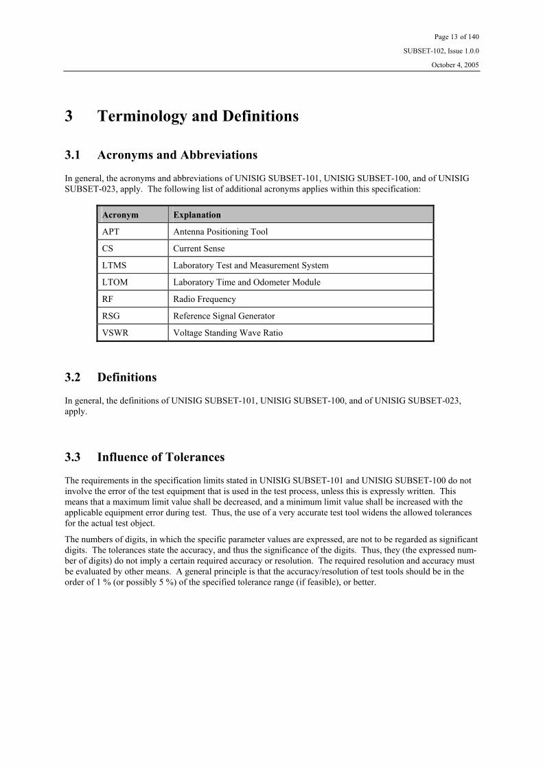
In general, the acronyms and abbreviations of UNISIG SUBSET-101, UNISIG SUBSET-100, and of UNISIG SUBSET-023, apply. The following list of additional acronyms applies within this specification:
Acronym Explanation
APT Antenna Positioning Tool
CS Current Sense
LTMS Laboratory Test and Measurement System
LTOM Laboratory Time and Odometer Module
RF Radio Frequency
RSG Reference Signal Generator
VSWR Voltage Standing Wave Ratio
3.2 Definitions
In general, the definitions of UNISIG SUBSET-101, UNISIG SUBSET-100, and of UNISIG SUBSET-023, apply.
3.3 Influence of Tolerances
The requirements in the specification limits stated in UNISIG SUBSET-101 and UNISIG SUBSET-100 do not involve the error of the test equipment that is used in the test process, unless this is expressly written. This means that a maximum limit value shall be decreased, and a minimum limit value shall be increased with the applicable equipment error during test. Thus, the use of a very accurate test tool widens the allowed tolerances for the actual test object.
The numbers of digits, in which the specific parameter values are expressed, are not to be regarded as significant digits. The tolerances state the accuracy, and thus the significance of the digits. Thus, they (the expressed num-ber of digits) do not imply a certain required accuracy or resolution. The required resolution and accuracy must be evaluated by other means. A general principle is that the accuracy/resolution of test tools should be in the order of 1 % (or possibly 5 %) of the specified tolerance range (if feasible), or better.

Page 14 of 140
SUBSET-102, Issue 1.0.0
October 4, 2005
4 Tests of the On-board Transmission Equipment
4.1 Reference Test Configuration
4.1.1 General
In order to minimise the possible influence from the surrounding environment, there shall be a volume around the Antenna Unit and the Reference Loop under test that is free from metallic objects. The minimum extent of this volume is defined in Figure 2. This volume is also referred to as “free space condition”. The space below 0.4 m (but above 0.7 m) underneath the Reference Loop shall not contain any solid metal planes, and only a few metallic supports are allowed within 0.7 m underneath the Reference Loop.
X
0.4 m / 0.7 m
Z
Min. 1 m
Min. 1 m
Min. 1 m
Min. 1 m
Min. 1 m
Min. 1 m
Min. 1 m
No metallic objects are allowed in this zone.
Antenna
Reference Loop center
center
Antenna Reference Loop
Figure 2: Definition of “free space” around the units under test

Page 15 of 140
SUBSET-102, Issue 1.0.0
October 4, 2005
4.1.2 Generic Test Set-up
The recommended general test set-up is shown in Figure 3 below. Annex E on page 134 gives an example of suitable test equipment.
Figure 3: Generic Test set-up for On-board Transmission Equipment tests
Items 10, 35, 36, and 37 are computer controlled via the Laboratory Test Management System (the computer control is intentionally not indicated in the figure). Additionally, the LTOM shall provide a trigger signal to item 13 (that starts a pre-defined sequence), the RSG_1 shall provide a trigger to item 44 indicating start of a ‘zero’ ASK bit, and the BTM function shall provide a trigger to the RSG_1 synchronising ASK bit generation with the Tele-powering modulation pulses. This requires an additional gate function because there is only one trigger input in the RSG_1. This is further detailed in Figure 4 and Figure 5.
The RS 232 link is a possible solution for transferring data files from the Laboratory Management System to the RSG.
Shaded units are units that are either new compared with the set-up used in UNISIG SUBSET-085, or require extended functionality for testing of the Interface ‘K’ functionality. Items 13 and 38 are further dealt with in Annex E on page 134. Item 44 is defined in Annex C on page 114.
Interface ‘VK’
2.
P1 P2
RS 232
IEEE 488 bus
APT
Antenna Unit
BTM function Interface ‘V1’
Adapter
Reference Loop Laboratory Test Management System
34.
Interface ‘V1’
LTOM
38.
Interface ‘V2’ Adapter
Interface ‘V2’
39.
40.
Interface ‘G’
Current Sense Balun
C.S.
7.
14.
Low Pass Filter
Low Pass Filter
Oscilloscope 37.
12.
12.
Attenuator
RF Switch
C
Low Pass Filter
29.
36.
P1 45.
Attenuator
Oscillo-scope
37.
31.
P2
Attenuator 4.
RF Amplifier 3. RSG_1
Trigger
Marker 1
13. Attenuator
RF Switch
36.
Spectrum Analyser
35.
Power Meter 2
10.
P3
Interface ‘VK’ Adapter
44. Interface ‘K’

Page 16 of 140
SUBSET-102, Issue 1.0.0
October 4, 2005
Figure 4: Specific triggering configuration
Figure 5: Triggering Timing Diagram
The RSG shall provide the possibility to adjust the “Trigger Out” such that it reflects the actual position of the expected ‘zero’ bit coming from the Balise (based on the actual modulation of the Tele-powering signal and the Up-link signal in the air gap). The principles for the required calibration are defined in section 4.1.7 on page 24.
Trigger Out
Trigger In
Sequence start
Marker 1
50 kHz clock
Adjustable delay
Trigger Out
Trigger In
Sequence start
Interface ‘VK’
BTM function
Laboratory Test Management System
LTOM
38.
RSG_1
Marker 1
13.
Interface ‘VK’ Adapter
44. Interface ‘K’
Gate
50 kHz clock

Page 17 of 140
SUBSET-102, Issue 1.0.0
October 4, 2005
4.1.3 Generic Test and Calibration Set-up Notes
The following aspects shall be respected for all test set-ups within this chapter (chapter 4). For some set-ups all aspects apply, but for others only some apply. The applicability is evident from the recommended test set-ups presented herein.
1. A spectrum analyser or similar equipment may substitute any power meter. However, this device shall be calibrated against a power meter prior to the test.
2. Unless otherwise stated herein, specific test tools are defined and detailed in UNISIG SUBSET-085.
3. It shall be verified that all harmonics are suppressed by at least 40 dB if power meters are used. Other-wise, sufficient filtering shall be performed.
4. All input and output ports of the Tests Antennas and Activation Antennas shall be equipped with suit-able baluns (these are part of the defined devices). See UNISIG SUBSET-085.
5. The attenuators connected before and after the RF power amplifier shall be positioned as close as pos-sible to the amplifier, and are used for ensuring good VSWR. The attenuator on the amplifier output is also used for protecting the amplifier from reflected power.
6. It is important that all RF cabling is of low loss double shielded type (e.g., RG 214). Furthermore, the cables shall be “de-bugged” using suitable ferrite clamps, evenly spaced along the cables, at distances less than 70 cm. The core material in the ferrite clamps shall be “Amidon 43” or equivalent.
7. Throughout this specification, ‘all zero’ sequences of amplitude modulation data shall be used unless explicitly otherwise specified.
8. RMS values are applicable unless otherwise explicitly stated. Integration time shall be selected in order to achieve sufficient measurement accuracy. Please observe that this is not applicable to for measure-ments of the ASK Up-link signal (see item 9 below).
9. The ASK Up-link signal shall be measured with an oscilloscope. After acquiring the actual waveform of a ‘zero’ bit, the definitions of UNISIG SUBSET-100 (section “Up-link Electrical Data”) shall be ap-plied in order to determine the Up-link signal level.
10. Iron bars shall be at least 200 mm from metal objects like a concrete floor containing iron reinforce-ments.
11. The cable carrying the 27 MHz signal to the Test Antenna (see UNISIG SUBSET-085) shall be identi-cal throughout the entire test process.
12. It is essential that the Reference Loops used during the tests fulfil the requirements of UNISIG SUBSET-085, and are characterised prior to testing.
13. Ferrite devices shall be used in order to reduce the RF field effect on the measurements. A balun basi-cally consists of a ferrite core (see UNISIG SUBSET-085 for more details). A balun shall be posi-tioned at the end of the cable, i.e., at the Reference Loop connector, unless otherwise explicitly stated.
14. All distances are in millimetres unless explicitly otherwise stated.
15. The attenuator (item 29) is used for ensuring a well defined 50 Ω source for driving the Reference Loop.
16. Please note that attenuation in the RF switches, balun, attenuator, and cabling shall be considered.

Page 18 of 140
SUBSET-102, Issue 1.0.0
October 4, 2005
17. The requirements on the RF switches are that the frequency range is DC to several hundred MHz, and that the attenuation is less than approximately 0.2 dB at 30 MHz. At 2 MHz to 30 MHz, isolation and VSWR should be better than 50 dB and 1:1.05 respectively. Switching time shall be minimised in or-der to limit the overall test time. The switch shall be able to withstand a current of at least 2 A.
18. The attenuator (item 29) may optionally be replaced by one with lower attenuation during Cross-talk tests if this is required in order to achieve sufficient signal levels for obtaining reliable test results. In this case special precautions must be considered in order to characterise the actual Reference Loop load conditions.
19. It is important to synchronise the observation of the BTM function reporting with the simulation of the Balise passage.
20. Item 45 (the low pass filter) is used to filter out the 27 MHz power signal sent by the Reference Loop towards the Power Amplifier. The recommended performance of the filter is found in UNISIG SUBSET-085. The filter shall be connected directly at the output of the attenuator close to the Refer-ence Loop.
21. Item 12 (the low pass filters) is used to filter out the 27 MHz signal sent by the Reference Loop towards the oscilloscope. The specifically recommended performance of the filter is found in UNISIG SUBSET-085. The filters shall be located directly at the Current Sense output of the balun.
22. The RSG should be programmed in order to issue a trigger pulse in correspondence to the centre of the dynamic up-link signal. This pulse triggers the oscilloscope to measure the Up-link signal level, and the LTOM to record the corresponding time and odometer data.
23. During the normal operation of the BTM, it needs to receive appropriate data from the LTOM (via In-terface ‘V2’). Unless otherwise explicitly stated, a speed of 100 km/h applies.
Page 19 of 140
SUBSET-102, Issue 1.0.0
October 4, 2005
4.1.4 Test Conditions
4.1.4.1 Nominal Conditions
4.1.4.1.1 General
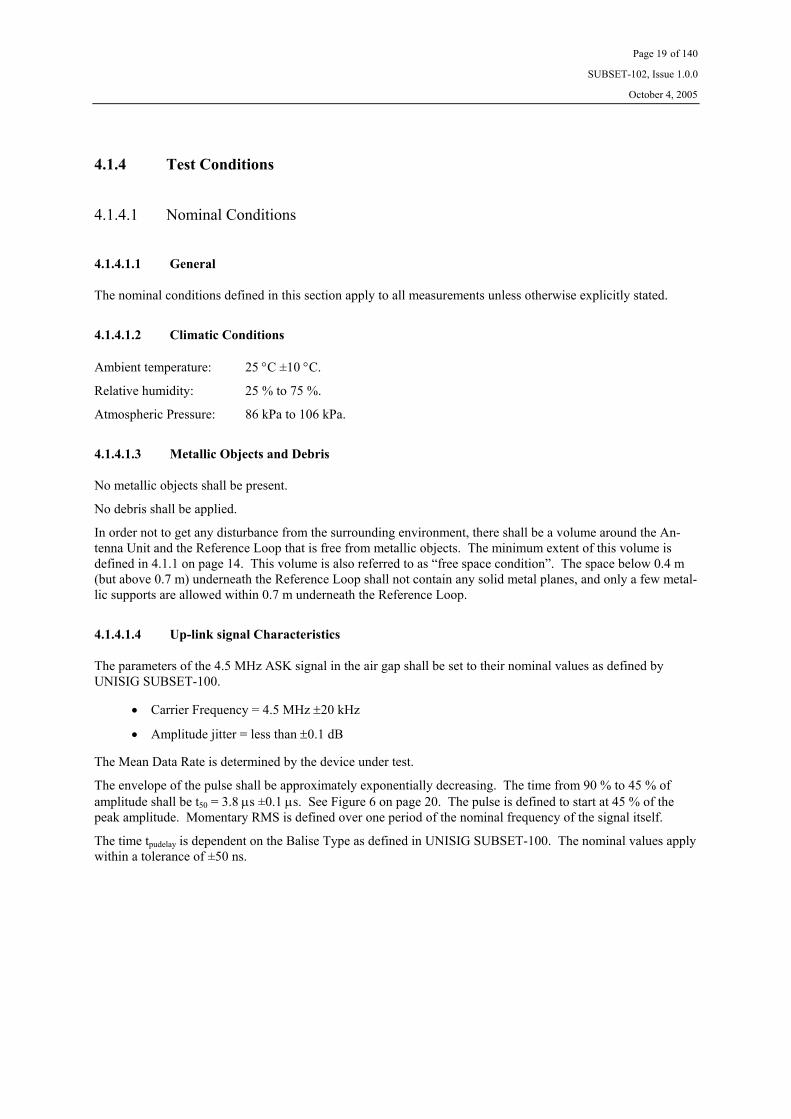
The nominal conditions defined in this section apply to all measurements unless otherwise explicitly stated.
4.1.4.1.2 Climatic Conditions
Ambient temperature: 25 °C ±10 °C.
Relative humidity: 25 % to 75 %.
Atmospheric Pressure: 86 kPa to 106 kPa.
4.1.4.1.3 Metallic Objects and Debris
No metallic objects shall be present.
No debris shall be applied.
In order not to get any disturbance from the surrounding environment, there shall be a volume around the An-tenna Unit and the Reference Loop that is free from metallic objects. The minimum extent of this volume is defined in 4.1.1 on page 14. This volume is also referred to as “free space condition”. The space below 0.4 m (but above 0.7 m) underneath the Reference Loop shall not contain any solid metal planes, and only a few metal-lic supports are allowed within 0.7 m underneath the Reference Loop.
4.1.4.1.4 Up-link signal Characteristics
The parameters of the 4.5 MHz ASK signal in the air gap shall be set to their nominal values as defined by UNISIG SUBSET-100.
• Carrier Frequency = 4.5 MHz ±20 kHz
• Amplitude jitter = less than ±0.1 dB
The Mean Data Rate is determined by the device under test.
The envelope of the pulse shall be approximately exponentially decreasing. The time from 90 % to 45 % of amplitude shall be t50 = 3.8 µs ±0.1 µs. See Figure 6 on page 20. The pulse is defined to start at 45 % of the peak amplitude. Momentary RMS is defined over one period of the nominal frequency of the signal itself.
The time tpudelay is dependent on the Balise Type as defined in UNISIG SUBSET-100. The nominal values apply within a tolerance of ±50 ns.

Page 20 of 140
SUBSET-102, Issue 1.0.0
October 4, 2005
Figure 6: Definition of Up-link pulses
4.1.4.1.5 Tele-powering Characteristics
The 27 MHz Tele-powering signal shall be toggling Tele-powering.
4.1.4.1.6 Telegram Contents
The Reference Loop shall transmit an ‘all zero’ sequence.
4.1.4.1.7 Tilt, Pitch, and Yaw
Tilt, Pitch, and Yaw angles shall be set to 0 (zero).
90 %
45 %
Time
t50
10 µs
Trigger level
tpudelay
Envelope of the Tele- powering magnetic field Time
Envelope of the Up- link magnetic field
Momentary RMS
0%
100%

Page 21 of 140
SUBSET-102, Issue 1.0.0
October 4, 2005
4.1.4.2 Specific Conditions
4.1.4.2.1 Tilt, Pitch, and Yaw
According to UNISIG SUBSET-100, tilting shall be applied to both the Antenna Unit and the Reference Loop.
Therefore, tilt angles shall be set to worst case maximum angle according to Antenna Unit manufacturer specifi-cation and the maximum tilting of the Reference Loop to the extreme value defined in UNISIG SUBSET-100. Both the Antenna Unit and the Reference Loop are subject to tilting, and the worst case combination applies.
According to UNISIG SUBSET-100, pitching shall be applied to both the Antenna Unit and the Reference Loop.
Therefore, pitch angles shall be set as defined below. Both the Antenna Unit and the Reference Loop are subject to pitching, and the worst case combination applies.
• Reference Loop pitch angle according to the extreme value defined in UNISIG SUBSET-100. • Antenna Unit pitch angle at maximum according to supplier specification.
The influence of yaw angles should not be tested, because no major influence is anticipated.
4.1.4.2.2 Debris
Test conditions, and the design and utilisation of the debris box, are defined by UNISIG SUBSET-085.
For the Reference Loop, the following conditions apply:
• Salt Water • Clear Water • Iron Ore (Magnetite)
The specific amount of debris applicable during testing is defined in UNISIG SUBSET-100.

Page 22 of 140
SUBSET-102, Issue 1.0.0
October 4, 2005
4.1.5 Test Tools and Procedures
The following list summarises the herein-defined On-board Transmission Equipment tests:
1. Electrical data 2. Data transmission 3. Timing requirements
4. Functional data
5. Link check functionality
6. Transmission and bit stream requirements:
6.1. Evaluation of radiation pattern
6.2. Transmission tests
6.3. Electrical Tele-powering characteristics
6.4. Maximum flux level
6.5. Up-link characteristics
6.6. Cross-talk immunity
6.7. Cross-talk immunity with cables
6.8. Balise Detect ability supervision
The following tools are anticipated for the On-board Transmission Equipment tests:
• Test Management System, used for co-ordinating the measurements, controlling the other tools of the test set-up, and for logging and reporting the test results
• Antenna Positioning Tool • Reference Loops (Standard or Reduced Size type) equipped with baluns • Test and Activation Antennas • Signal Generators • RF instruments and accessories of general use • Reference Units for debris and cables • Interface adapters

Page 23 of 140
SUBSET-102, Issue 1.0.0
October 4, 2005
4.1.6 Determination of ASK Up-link Signal Level
Figure 7: Determination of ASK Up-link Signal Level
The frequency of the sine and cosine signals in the multiplication process shall be close to 4.35 MHz.
The first integration (after the multiplication process) shall provide integration over one period of the 4.35 MHz sine signal.
The last integration shall provide integration over 10 us starting such that the output result is maximised.
The process above may be performed such that the input signal (covering at least one complete ‘zero’ bit) is in real time sampled at a sampling rate of 200 Msamples/s, and the resulting samples are stored in a file for subse-quent off-line software processing. Sampling shall start at least 200 ns before the start of the ASK bit in order ensure capturing of the entire bit.
For simplicity, select the frequency of the sine and cosine signals in the multiplication process to 200 MHz/46 = 4.3478 MHz (which is close enough to 4.35 MHz). This means that 46 samples are obtained over one period of the modulation signal.
The sampled input signal should be multiplied sample by sample by a discrete synthetically produced sine and cosine signal with the peak amplitude 2 in order to maintain the scaling of the input signal. The output result from the multiplication process is two vectors of the same length as the input signal vector.
The succeeding integration (in each of the two branches) shall be performed such that 46 consecutive samples are summed in a sliding 46 bit long window. Please observe that the result of each summation shall be divided by 46 to maintain the scaling. The result is two vectors with the length of the input vector minus 45 samples (the first 45 sums can not be used since the sliding window was not yet filled up).
Thereafter, the square of each result of the output vectors from the integration shall be calculated, and the ob-tained result from each of the two branches shall be summed sample by sample. The result is one vector with the same length as after the integration process.
The next step is to calculate the square root out of each sample in the vector. This is followed by division by 2 in order to convert peak scale to RMS scale. The result of this is one vector with the same length as after the integration process.
The final step is to perform integration over 10 us. The method is that 2000 consecutive samples are summed in a sliding 2000 bit long window. Please observe that the result of each summation shall be divided by 2000 to maintain the scaling. The output result is obtained in the position of the sliding window where the resulting sum is maximised. In case an on-line process is required, the position of the integration window can be regarded deterministic after it has once been determined.
Input Sampler
2 sin 2πft
2 cos 2πft
∫
∫
x2
x2 2
1 ∫
Output
X

Page 24 of 140
SUBSET-102, Issue 1.0.0
October 4, 2005
4.1.7 Calibration of Up-link data generation
The position of the trigger pulse sent to the Interface ‘VK’ adapter and the Up-link signal generation shall be correctly positioned with respect to the modulation pulses of the Tele-powering signal. Use the test set-up defined in Figure 3 on page 15 and Figure 4 on page 16.
1. Position the Reference Loop at [X = 200, Y = 200, Z = 460] relative to the reference position of the On-board antenna.
2. Switch on the Tele-powering signal from the BTM. 3. Set the RF switches such that the oscilloscope shows the Tele-powering signal received by the Refer-
ence Loop. 4. Connect the other channel of the oscilloscope to the “Trigger Out” from the RSG_1. 5. Start a suitable sequence from the LTMS (such that the “sequence start” pulse is obtained). 6. Measure the time between the 90 % level of the falling edge of the Tele-powering modulation pulse and
the negative edge of the “Trigger Out” pulse from the RSG_1. 7. Adjust a delay within the RSG_1 such that the time measured in step 6 corresponds to the desired value
of tpudelay. 8. Set the RF switches such that the oscilloscope shows the Up-link signal (as measured in the Current
Sense output of the Current Sense Balun). 9. Measure the time between the 45 % level of the rising edge of the Up-link signal ‘zero’ bit and the
negative edge of the “Trigger Out” pulse from the RSG_1. 10. Adjust a delay within the RSG_1 such that the time measured in step 9 is zero within the accuracy de-
fined in section E3.3 on page 135.

Page 25 of 140
SUBSET-102, Issue 1.0.0
October 4, 2005
4.2 Laboratory Tests, Alternative 1 Interface
4.2.1 Electrical Data
4.2.1.1 General Description, Electrical Data
This section outlines the tests needed for ensuring that the electrical data for Interface ‘K’ is fulfilled.
Since it is likely that commercially available transmitter circuits are used, it is in such a case sufficient to ensure (show guarantees) that the actual device fulfils the applicable standard. Specifically developed transmitter cir-cuits must be fully characterised in order to show compliance with the applicable standard.
The principle above also applies to ensuring the defined isolation requirements.
Since the type of cable and the cable length is not harmonised, the requirements defined by the standard shall be fulfilled at the input of the receiver(s).
4.2.1.2 Conditions, Electrical Data
The maximum cable length specified by the manufacturer shall be considered.
The maximum amount of loading receivers and (non active) transmitters shall be considered. See definitions in UNISIG SUBSET-101.
4.2.1.3 Acceptance Criteria, Electrical Data
a. The limits defined by the RS 485 standard shall be fulfilled.
b. The isolation requirements defined by the EN 50155 standard shall be fulfilled.

Page 26 of 140
SUBSET-102, Issue 1.0.0
October 4, 2005
4.2.2 Data Transmission
4.2.2.1 General Description, Data Transmission
This section defines the test procedure for verifying the data transmission. The test procedure includes verifica-tion of the following properties:
• Presence of start and stop bits
• Correctness of Bi Phase Level (BPL) coding
The order of the transmitted information is implicitly verified during the tests of section 4.2.4 on page 28.
4.2.2.2 Test Pattern, Data Transmission
The RSG shall be programmed such that a repetitive 00001110101 ASK bit pattern is continuously transmitted through the air gap (Interface ‘G’).
4.2.2.3 Test Procedure, Data Transmission
1. Position the antenna such that the manufacturer dependent nominal vertical distance is obtained with respect to the Reference Loop, and that X=0 and Y=0 with respect to the Reference Loop.
2. Adjust the output level from the RSG such that an Up-link current of Iu1 +3 dB is obtained. Please ob-serve that the Up-link current must be modulated as defined in Figure 8 on page 36.
3. Temporarily connect the oscilloscope to Interface ‘K’. Please observe that a floating measurement shall be performed (e.g., using two channels and performing a differential measurement). The oscillo-scope should be triggered from the output of the RSG.
4. Record the resulting transmission of at least one repetition of the defined pattern.
5. Verify the existence of start and stop bits.
6. Verify the correctness of the Bi Phase Level (BPL) coding.
4.2.2.4 Acceptance Criteria, Data Transmission
a. The test shall verify the existence of start and stop bits as specified in UNISIG SUBSET-101.
b. The test shall verify that the Bi Phase Level (BPL) coding is in accordance with UNISIG SUBSET-101.

Page 27 of 140
SUBSET-102, Issue 1.0.0
October 4, 2005
4.2.3 Timing Requirements
4.2.3.1 General Description, Timing Requirements
This section defines the test procedure for verifying the timing requirements. The test procedure includes verifi-cation of the following properties:
• Correctness of 50 kHz ASK bit data rate
• Correctness of phase position between various channels (if more than one is implemented)
• Correctness of the Bi Phase Level (BPL) clock
• Propagation delay from Interface ‘G’ to Interface ‘K’
4.2.3.2 Test Pattern, Timing Requirements
The RSG shall be programmed such that a repeated 40 ASK bit pattern starting with 8 consecutive ‘zeros’ fol-lowed by 8 consecutive ‘ones’, and finally followed by toggling ‘zeros’ and ‘ones’ up to the end of the of the pattern is continuously transmitted through the air gap (Interface ‘G’).
4.2.3.3 Test Procedure, Timing Requirements
1. Position the antenna such that the manufacturer dependent nominal vertical distance is obtained with respect to the Reference Loop, and that X=0 and Y=0 with respect to the Reference Loop.
2. Adjust the output level from the RSG such that an Up-link current of Iu2 is obtained. Please observe that the Up-link current must be modulated as defined in Figure 8 on page 36.
3. Temporarily connect the oscilloscope to Interface ‘K’. Please observe that a floating measurement shall be performed (e.g., using two channels and performing a differential measurement). The oscillo-scope should be triggered from the output of the RSG.
4. Record the resulting transmission of at least one full bit pattern repetition in the air gap.
5. Evaluate the 50 kHz ASK bit data rate.
6. In case more than one channel is implemented, measure the phase position between various channels.
7. Evaluate the Bi Phase Level (BPL) clock performance (jitter).
8. Evaluate the propagation delay between the air gap signal and the data transmitted through Inter-face ‘K’.
9. Record the resulting transmission of at least 500 ‘zero’ bits and one ‘one’ bits in the air gap, and evalu-ate the number of stop bits for all ASK bits.
4.2.3.4 Acceptance Criteria, Timing Requirements
a. The ASK bit data rate shall be 50 kbits/s within the tolerance specified in UNISIG SUBSET-100.
b. The phase difference between the various channels (if more than one is implemented) shall be less than what is specified in UNISIG SUBSET-101.
c. The jitter on the Bi Phase Level (BPL) clock shall be less than defined in UNISIG SUBSET-101.
d. The propagation delay shall be less than what is specified in UNISIG SUBSET-101.
e. The number of stop bits shall be 24 to 26.
Data shall not be evaluated in case a forced link test occurs.

Page 28 of 140
SUBSET-102, Issue 1.0.0
October 4, 2005
4.2.4 Functional Data
4.2.4.1 General Description, Functional Data
This section defines the test procedure for verifying the correct transmission of data from a functional perspec-tive. The test procedure includes verification of the following properties:
• Transmission of ‘Data for Balise Detection’ (BD)
• Transmission of ‘Data for Telegram Decoding’ (TD)
• Transmission of ‘ERTMS Unavailability’ upon switching Tele-powering off (EU)
• Transmission of ‘Eurobalise Reception’ upon reception of Eurobalises (EB)
• Transmission of ‘Link Test Data’ (LT)
• Transmission of ‘Signal Strength Data’ (S)
• Transmission of ‘Antenna/BTM ID Data’ (A)
• Transmission of ‘Link ID Data’ (L)
• Transmission of ‘Bit Counter’ (B)
• Correctness of CRC generation
In case multiple channels are implemented, the requirements related to diversified data defined in UNISIG SUBSET-101 will also be verified from a transmitter perspective. Finally, simulation of a permanently failing BTM functionality is also simulated (including absence of BPL coding).
4.2.4.2 Test Patterns, Functional Data
4.2.4.2.1 General
In general, the RSG shall be programmed such that a 00001110101 ASK bit pattern is continuously transmitted through the air gap (Interface ‘G’).
4.2.4.2.2 Specific FSK pattern
A specific pattern that is to be transmitted is a valid Eurobalise FSK Up-link signal. The Up-link signal shall be set to the nominal conditions defined in UNISIG SUBSET-085, and carry the defined Telegram 17.
Page 29 of 140
SUBSET-102, Issue 1.0.0
October 4, 2005
4.2.4.3 Test Procedure, Functional Data
1. Position the antenna such that the manufacturer dependent nominal vertical distance is obtained with respect to the Reference Loop, and that X=0 and Y=0 with respect to the Reference Loop.
2. Adjust the output level from the RSG such that an Up-link current of Iu0 -20 dB is obtained. Please observe that the Up-link current must be modulated as defined in Figure 8 on page 36. Please also observe that the current measured by the oscilloscope needs to be compensated for the B-factor of the Reference Loop (i.e., the measured target current shall be the desired Reference Loop current divided by B). Please observe also the definitions of UNISIG SUBSET-100 for the definition of the signal level.
3. Record, via Interface ‘VK’, the resulting transmission of at least one ‘zero’ bit and one ‘one’ bit in the air gap. The recording shall be synchronised with the transmission of the air gap signal, and data shall not be evaluated in the potential presence of a link check.
4. Increase the output level from the RSG such that the Up-link current is increased by 3 dB.
5. Record, via Interface ‘VK’, the resulting transmission of at least one ‘zero’ bit and one ‘one’ bit in the air gap. The recording shall be synchronised with the transmission of the air gap signal, and data shall not be evaluated in the potential presence of a link check.
6. Repeat steps 4 and 5 until the output level from the RSG is such that an Up-link current of Iu3 is ob-tained.
7. Adjust the output level from the RSG such that an ASK Up-link current of Iu2 is obtained. Please observe that the Up-link current must be modulated as defined in Figure 8 on page 36.
8. Temporarily command Tele-powering off instead of Tele-powering on.
9. Record, via Interface ‘VK’, the resulting transmission of at least one ‘zero’ bit and one ‘one’ bit in the air gap. The recording shall be synchronised with the transmission of the air gap signal.
10. Temporarily transmit the FSK Up-link sequence defined in section 4.2.4.2.2 on page 28.
11. Record, via Interface ‘VK’, the resulting transmission over a period of time of 2 ms. The recording shall be synchronised with the transmission of the air gap signal.
12. Temporarily stop transmitting any Up-link signal via the air gap.
13. Record, via Interface ‘VK’, the resulting transmission over a period of time exceeding 500 ms.
14. For equipment making judgement on permanent errors, temporarily introduce a permanent error in the On-board Transmission Function.
15. Record, via Interface ‘VK’, the resulting transmission over a period of time exceeding 500 ms. The recording shall be synchronised with the transmission of the air gap signal.
16. Ensure that the BTM functionality is reset to proper operation.
17. In case multiple antenna/BTM functions are implemented, steps 2 through 13 shall be repeated for all possibilities.
18. In case more than one transmission channel is implemented (due to either redundancy or safety), steps 2 through 13 shall be repeated for all channels.

Page 30 of 140
SUBSET-102, Issue 1.0.0
October 4, 2005
4.2.4.4 Acceptance Criteria, Functional Data
For each of the acquisitions performed in steps 3 and 5, it shall be verified that:
a. ‘Data for Balise Detection’ indicates ‘zero’ synchronised with ‘zero’ in the air gap signal when the sig-nal is above the fix threshold, and ‘one’ when the signal is below the fix threshold. ‘Data for Balise Detection’ indicates ‘one’ synchronised with ‘one’ the air gap signal when the signal is below the fix threshold, and also ‘one’ when the signal is above the fix threshold. The exception is that also indica-tion of ‘zero’ is acceptable at very strong input signals provided that Data for Telegram Decoding is transmitted.
b. ‘Data for Telegram Decoding’ indicates either ‘zero’ or ‘one’ synchronised with ‘zero’ in the air gap signal when the signal is below the fix threshold. ‘Data for Telegram Decoding’ indicates ‘zero’ syn-chronised with ‘zero’ in the air gap signal when the signal is above the fix threshold. ‘Data for Tele-gram Decoding’ always indicates ‘one’ synchronised with ‘one’ in the air gap signal regardless of sig-nal level. If this optional data is not explicitly provided, the contents shall be identical to ‘Data for Bal-ise Detection’.
c. ‘ERTMS Unavailability’ is set to logical ‘zero’.
d. ‘Eurobalise Reception’ is set to logical ‘zero’.
e. ‘Link Test Data’ is set to logical ‘zero’.
f. In case ‘Signal Strength Data’ is not provided, the corresponding four data bits shall be set to logical ‘zero’. In case Signal Strength Data is provided, the corresponding four data bits shall indicate a com-pany specific binary value in the range from 0001 to 1111. Successive readings shall be either equal or higher when the output level from the RSG is successively increased. It is acceptable with a maximum fluctuation of one LSB. The regions for transition from one value to another may be manufacturer spe-cific.
g. ‘Antenna/BTM ID Data’ is according to the intended antenna/BTM function. Rare occurrence of cor-ruption is acceptable as long as this does not violate the specified error rate.
h. Transmission of ‘Link ID Data’ is according to the intended channel. Rare occurrence of corruption is acceptable as long as this does not violate the specified error rate.
i. The ‘Bit Counter’ is increasing by one (modulo 8) for each ASK bit.
j. CRC is correct. Rare occurrence of corruption is acceptable as long as this does not violate the speci-fied error rate.
For the acquisitions performed in step 9, it shall be verified that:
k. ‘ERTMS Unavailability’ is set to logical ‘one’.
For the acquisition performed in step 11, it shall be verified that:
l. ‘Eurobalise Reception’ is set to logical ‘one’ no later than the in UNISIG SUBSET-101 specified time after the start of the transmission of the specific pattern via Interface ‘VK’.

Page 31 of 140
SUBSET-102, Issue 1.0.0
October 4, 2005
For the acquisition performed in step 13, it shall be verified that:
m. Link check patterns are transmitted in accordance with the requirements of UNISIG SUBSET-101.
For the acquisition performed in step 15, it shall be verified that:
n. The interface ‘K’ channel activity is terminated (including no BPL coding) after the introduction of the failure condition.
Specifically for step 18 (if applicable), aspects on diversified data shall be considered. See requirements in UNISIG SUBSET-101.

Page 32 of 140
SUBSET-102, Issue 1.0.0
October 4, 2005
4.2.5 Link Check Functionality
4.2.5.1 General Description, Link Check Functionality
This section defines the test procedure for verifying the correct transmission of signals used for on-line supervi-sion of the Interface ‘K’ link. The test procedure includes verification of the following properties:
• Time between transmissions of link check patterns
• Correctness of link check pattern
• Transmission of ‘Link Test Data’ upon progressing transmission tests
• Blocking of link checks during reception of Balise data
4.2.5.2 Test Pattern, Link Check Functionality
In the beginning of the test (up to step 3 in section 4.2.5.3), there shall be no transmission of Up-link signals through the air gap.
In the second phase of the test (from step 4 to step 5), the RSG shall be programmed such that a repetitive ASK bit pattern including the maximum number of allowed consecutive ‘ones’ (see UNISIG SUBSET-101) is con-tinuously transmitted through the air gap (Interface ‘G’).
In the third phase of the test (from step 6 to step 7), the RSG shall be programmed such that the Up-link signal pattern constitutes Eurobalise data as defined in section 4.2.4.2.2 on page 28, which is continuously transmitted through the air gap (Interface ‘G’).
4.2.5.3 Test Procedure, Link Check Functionality
1. Without transmitting any Up-link signal, record the resulting transmission via Interface ‘VK’ for a pe-riod of time exceeding 2 s.
2. Calculate the time between succeeding link checks.
3. Position the antenna such that the nominal vertical distance is obtained with respect to the Reference Loop, and that X=0 and Y=0 with respect to the Reference Loop.
4. Start transmitting the ASK Up-link signal, and adjust the output level from the RSG such that an Up-link current of Iu1 is obtained. Please observe that the Up-link current must be modulated as defined in Figure 8 on page 36. Please also observe that the current measured by the oscilloscope needs to be compensated for the B-factor of the Reference Loop (i.e., the measured target current shall be the de-sired Reference Loop current divided by B). Please observe also the definitions of UNISIG SUBSET-100 for the definition of the signal level.
5. Record the resulting transmission via Interface ‘VK’ for a period of time sufficient to cover a period of time exceeding 2 s.
6. Switch over to transmitting the FSK Up-link signal, and adjust the output level from the RSG such that an Up-link current of Iu1 is obtained.
7. Record the resulting transmission via Interface ‘VK’ for a period of time sufficient to cover a period of time exceeding 2 s.
8. In case multiple antenna/BTM functions are implemented, steps 1 through 7 shall be repeated for all possibilities.
9. In case more than one transmission channel is implemented (due to either redundancy or safety), steps 1 through 7 shall be repeated for all channels.

Page 33 of 140
SUBSET-102, Issue 1.0.0
October 4, 2005
4.2.5.4 Acceptance Criteria, Link Check Functionality
For the acquisition performed up to step 3, it shall be verified that the link test includes the four mandatory ASK bits defined in UNISIG SUBSET-101. In case the optional ASK bits (as denied in UNISIG SUBSET-101) are transmitted, it shall be verified that no more than 15 additional bits are transmitted. It shall also be verified that the Link Test data is transmitted consistently with the link test pattern.
For the acquisition performed up to step 3, it shall be verified that there is at least one approved link test within the defined sliding 250 ms time interval.
For the acquisition performed in step 5, it shall be verified that the following is transmitted for a period of time not exceeding 1 s:
a. ‘Data for Balise Detection’ indicates ‘zero’ synchronised with ‘zero’ in the air gap signal. ‘Data for Balise Detection’ indicates ‘one’ synchronised with ‘one’ in the air gap signal.
b. ‘Data for Telegram Decoding’ shall be identical to ‘Data for Balise Detection’. If this optional data is not explicitly provided, the contents shall also be identical to ‘Data for Balise Detection’.
c. ‘ERTMS Unavailability’ is set to logical ‘zero’.
d. ‘Eurobalise Reception’ is set to logical ‘zero’.
e. ‘Link Test Data’ is set to logical ‘zero’.
f. In case ‘Signal Strength Data’ is not provided, the corresponding four data bits shall be set to logical ‘zero’. In case ‘Signal Strength Data’ is provided, the corresponding four data bits shall represent rele-vant data for the selected Up-link signal level.
g. ‘Antenna/BTM ID Data’ is according to the intended antenna/BTM function. Rare occurrence of cor-ruption is acceptable as long as this does not violate the specified error rate.
h. Transmission of ‘Link ID Data’ is according to the intended channel. Rare occurrence of corruption is acceptable as long as this does not violate the specified error rate.
i. The ‘Bit Counter’ is increasing by one (modulo 8) for each ASK bit.
j. CRC is correct. Rare occurrence of corruption is acceptable as long as this does not violate the speci-fied bit error rate.
After a period of time greater than 0.5 s but not exceeding 1 s, it shall be verified that a link test is transmitted also in the presence of transmission of ASK Up-link data.

Page 34 of 140
SUBSET-102, Issue 1.0.0
October 4, 2005
For the acquisition performed in step 7, it shall be verified that the following is transmitted for a period of time not exceeding 1 s:
k. ‘Data for Balise Detection’ indicates an all ‘zero’ pattern.
l. ‘Data for Telegram Decoding’ indicates an all ‘zero’ pattern.
m. ‘ERTMS Unavailability’ is set to logical ‘zero’.
n. ‘Eurobalise Reception’ is set to logical ‘one’.
o. ‘Link Test Data’ is set to logical ‘zero’.
p. ‘Tele-powering Data’ is set to logical ‘one’.
q. In case ‘Signal Strength Data’ is not provided, the corresponding four data bits shall be set to logical ‘zero’. In case ‘Signal Strength Data’ is provided, the corresponding four data bits shall represent rele-vant data for the selected Up-link signal level.
r. ‘Antenna/BTM ID Data’ is according to the intended antenna/BTM function. Rare occurrence of cor-ruption is acceptable as long as this does not violate the specified error rate.
s. Transmission of ‘Link ID Data’ is according to the intended channel. Rare occurrence of corruption is acceptable as long as this does not violate the specified error rate.
t. The ‘Bit Counter’ is increasing by one (modulo 8) for each ASK bit.
u. CRC is correct. Rare occurrence of corruption is acceptable as long as this does not violate the speci-fied bit error rate.
After a period of time greater than 0.5 s but not exceeding 1 s, it shall be verified that a link test is transmitted also in the presence of transmission of FSK Up-link data.

Page 35 of 140
SUBSET-102, Issue 1.0.0
October 4, 2005
4.2.6 Verification of Transmission and Bit Stream Requirements
4.2.6.1 General Description, Transmission and Bit Stream Requirements
This section (4.2.6) defines test procedures for Antenna Unit and BTM function tests. The test procedures in-clude the following steps with partially different test set-ups and under various test conditions:
• Characterisation of radiation pattern and creation of signal pattern for dynamic tests
• Transmission tests
• Tele-powering characteristics tests and test of maximum flux level
• Up-link characteristics tests
• Cross-talk tests
Each Antenna Unit - BTM function combination shall be tested with the different Reference Loops. For the purpose of the Reduced Size Reference Loop, only transversal mounting orientation shall apply.
Reference Loop currents and the flux values shall be in accordance with the input-to output characteristic defini-tion of UNISIG SUBSET-100. Please observe that the Up-link current measured by the oscilloscope needs to be compensated for the B-factor of the Reference Loop (i.e., the measured target current shall be the desired Refer-ence Loop current divided by B). Please observe also the definitions of UNISIG SUBSET-100 for the definition of the signal level.
See also specific notes included in section 4.1.3 on page 17.

Page 36 of 140
SUBSET-102, Issue 1.0.0
October 4, 2005
4.2.6.2 Evaluation of Radiation Pattern
4.2.6.2.1 General Description, Evaluation of Radiation Pattern
The purpose of this test is to find the weakest possible Balise signal and activation flux, during static conditions, where the Antenna Unit - BTM function combination has the ability to enable detection and decoding of the Balise for static geometrical points in the region above the Reference Loop (i.e., exploring the behaviour of the BTM function threshold Vth, and the Tele-powering flux). It shall also provide information on side lobe charac-teristics. The results from this test shall be used as input for creating the signal pattern for a simulated dynamic Balise passage as defined in section 4.2.6.3 on page 40, and used during the applicable tests of this document.
The procedure includes two steps. One is to measure the actual Tele-powering flux through the Reference Loop. The other is to determine the required Up-link current through the Reference Loop corresponding to the BTM function threshold (Vth). This corresponding current is denominated Ith. Tele-powering and Up-link characteri-sation are performed in two different phases (please observe that the measurement accuracy shall be maintained in the presence of 27 MHz Tele-powering signal when performing Up-link signal measurements).
During Tele-powering measurements, the actual flux φ through the Reference Loop is measured.
During Up-link checking, the Reference Loop shall be connected to a signal generator generating an ASK Up-link signal that simulates a representative Balise passage (see Figure 8 below), and carrying a sequence as de-fined below with a peak current level stepwise altered in order to reach Ith (as described below). The BTM func-tion output response shall be observed via Interface ‘VK’. The BTM function is set in normal operational mode.
5 ms 5 ms
tdur = 20 ms
ITH
Time
Figure 8: Up-link signal
The odometer input signal shall be selected such that the flat part of the sequence according to Figure 8 above corresponds to approximately 0.5 m at a speed of 100 km/h (the entire sequence from start of rising edge to end of falling edge corresponds to approximately 0.75 m).
The transmitted Up-link sequence shall in general be a pattern that is an “all zero” sequence, but for the so-called reference position, [X = 0, Y = 0, Z = maximum height], it shall be evaluated if there are significant dif-ferences (more than 0.5 dB) in the evaluated threshold when applying also the repetitive sequences:
• 010101010101010101010101………….
• 111111101111111011111110…………….
In case there are significant differences, also the worst case condition in terms of consecutive ‘ones’ for the related coding strategies should be considered. If significant differences are observed, then the thresholds evalu-ated with an “all zero” sequence shall be adjusted according to the evaluation. The highest possible corrected threshold (with the worst case sequence) shall be used for sensitivity oriented tests, and the lowest possible corrected threshold shall be used for cross-talk oriented tests.

Page 37 of 140
SUBSET-102, Issue 1.0.0
October 4, 2005
During Up-link checking, a start value of Iu1 through the Reference Loop shall be selected. Thereafter, the cur-rent level is either increased or decreased in steps until the BTM function threshold is reached. For increased current levels, steps of 0.2 dB are applicable up to Iu1 + 7 dB, thereafter steps of 0.5 dB apply up to a maximum current level of Iu1 +24 dB. For decreasing current levels, steps of 0.5 dB apply down to the level Ith. Please observe that potential hysteresis phenomena shall be evaluated and considered. In case of hysteresis, Ith shall always be determined for increasing current levels.
An ‘all zero’ data sequence shall be used during this process (except for in the reference position, see above). The criterion for having reached the receiver threshold is that it is verified that at least 90 % of the received bits are ‘zeros’. Both ‘Data for Balise Detection’ and ‘Data for Telegram Decoding’ shall be evaluated.
Actual Tele powering flux φ, and the threshold current Ith are recorded for each single geometrical test point defined in chapter A1 of Annex A on page 109. This procedure shall be repeated for all the test conditions de-fined in section 4.1.4 on page 19 and limited by the test matrices of chapters A3 and A4 in Annex A on pages 111 and 112 respectively. It is important that the position [X = 0, Y = 0, Z = maximum height] is explored, because this forms the reference for the calculations of section 4.2.6.3 on page 40. The threshold current for this position will be denominated ITHREF.

Page 38 of 140
SUBSET-102, Issue 1.0.0
October 4, 2005
4.2.6.2.2 Test Procedure, Evaluation of Radiation Pattern
The test set-up in accordance with section 4.1.2 on page 15 applies.
1. Position the Antenna Unit in the geometrical test point [X = 0, Y = 0, Z = maximum height], and select nominal test conditions defined by section 4.1.4.1 on page 19.
2. Set the RF switches in positions P2 and P3 respectively (thus connecting power meter 2).
3. Command the BTM function to its normal operational mode regarding toggling Tele-powering, or to any other mode equivalent to this (from the point of view of the Up-link diagram evaluation).
4. Record the value of power meter 2.
5. Repeat step 4 for all remaining geometrical test points defined by chapter A1 on page 109 and chapter A3 on page 111.
6. Calculate and record the flux through the Reference Loop using the following equation:
27
2
2
5050
50
f
ZPB loopPM
⋅⋅
+⋅⋅⋅
=Φπ
where: PPM2 is power recorded by power meter 2 B is the Reference Loop transfer matching ratio Zloop is the actual impedance of the Reference Loop in the absence of any antenna f27 is the Tele-powering frequency (27.095 MHz)
Please observe that the attenuation and impedance of the RF switch, the attenuator, and the current sense balun have to be considered (characterised prior to testing). This is not considered in the equation above.
7. Set the RF switch in position P1 (thus enabling generation of Up-link signals).
8. Set the arbitrary generator to generate an Up-link signal in accordance with Figure 8 on page 36 and section 4.1.4.1.4 on page 19. The initial current setting shall be the minimum controllable current (in the order of 1 mA). The current is measured by the oscilloscope, and the related transfer response of the Current Sense balun is in accordance with UNISIG SUBSET-085. Please observe that the current meas-ured by the oscilloscope needs to be compensated for the B-factor of the Reference Loop (i.e., the meas-ured target current shall be the desired Reference Loop current divided by B). Please observe also the definitions of UNISIG SUBSET-100 for the definition of the signal level. Set the time and odometer in-formation to comply with a speed of 100 km/h.
9. Position the Antenna Unit in the geometrical test point [X = 0, Y = 0, Z = maximum height].
10. Record the output from the BTM function (via Interface ‘VK’), and determine whether the Up-link signal was above or below the BTM function threshold (Vth). That is reception of at least 90 % of the expected amount of ‘zeros’. Please observe the requirement in section 4.2.6.2.1 on page 36 regarding measure-ments with different patterns in the reference position (only).
11. In case that the signal was above the threshold, gradually decrease the current level in steps as defined by section 4.2.6.2.1 on page 36 until the signal drops below the threshold. In case the signal was below the threshold, gradually increase the current level in steps as defined by section 4.2.6.2.1 on page 36 until the signal exceeds the threshold. Record the actual threshold value Ith. Please observe the note regarding hysteresis in section 4.2.6.2.1 (this may always require determination of Ith for increasing current levels).

Page 39 of 140
SUBSET-102, Issue 1.0.0
October 4, 2005
12. Repeat steps 10 and 11 for all remaining geometrical test points defined by chapter A1 on page 109 and chapter A3 on page 111. In order to speed up the procedure, the iterative evaluation of the new threshold value Ith can be done starting from an optimised value based on the values evaluated for the previous nearby positions.
13. Repeat steps 1 through 12 for all specific test conditions defined by section 4.1.4.2 on page 21 and chap-ter A3 on page 111. Please observe that “nominal conditions” of step 1 is substituted by the relevant “specific condition” for each subsequent pass.
14. Repeat steps 1 trough 4 and 7 through 11 at the temperature extremes, and evaluate possible change of performance. Potential change of performance shall be considered in calculations of section 4.2.6.3 on page 40.
It must be verified that reliable Up-link measurements can be performed in the presence of the applicable 27 MHz Tele-powering signal.

Page 40 of 140
SUBSET-102, Issue 1.0.0
October 4, 2005
4.2.6.3 Creation of Signal Pattern for Dynamic Tests
4.2.6.3.1 General Description, Creation of Signal Pattern for Dynamic Tests
The aim is to create a time varying 4.5 MHz current through the Reference Loop that simulates a Balise passage without any physical movements of the equipment. In other words, it is a time dependent modulation of the Up-link signal (in addition to the normal modulation forming the ASK signal). During the following applicable tests of this document, the Reference Loop will be positioned in [X = 0, Y = 0, Z = maximum height]. This is the geometrical reference point.
The recorded Tele-powering flux level (φ in Figure 9 on page 42) shall be used for determining the response from two different worst case Balises (ILOW and IHIGH in Figure 9 on page 42), utilising the lower and upper limits of the transfer response curve defined by UNISIG SUBSET-100.
Thereafter, considering data (Ith) obtained during the radiation pattern tests defined by section 4.2.6.2 on page 36, a signal pattern simulating a Balise passage shall be calculated. For all geometrical positions (and all appli-cable test conditions) the actual current required for passing the BTM function threshold (Ith) shall be compared with ITHREF (see below). A special geometrical test point is [X = 0, Y = 0, Z = maximum height] that serves as reference. The corresponding threshold value is denominated ITHREF. Please observe the potential correction required in case there are significant differences for different test patterns.
The φ and Ith patterns recorded along the X-axis for each lateral and vertical displacement, and for each Balise behaviour (illustrated in Figure 9 on page 42), will have to be stored in separate files in order to use them for simulating dynamic signals of Balise passages.
The signal pattern to be calculated (and simulated) is the Up-link signal current through the Reference Loop, constituting the sum of the weakest or strongest possible Balise and the difference between Ith and ITHREF (con-sidering the correct sign). Furthermore, realistic start-up behaviour of the Balise shall be simulated (including a certain delay time Tbal) for the weakest possible Balise. The latter includes that the Balise is inactive until a flux level of φd1 is reached, and that a delay time Tbal according to UNISIG SUBSET-100 is applicable. Each simu-lated Balise passage shall be normalised with respect to ITHREF.
In order to visualise that data has to be collected once only, followed by proper scaling to simulate a desired velocity, the example of signal pattern generation is split up in two parts (see Figure 9 on page 42 and Figure 10 on page 43). The first part, required to be performed once only, deals with position related events (see Figure 9). The second part, to be repeated for each single velocity to be simulated, deals with time related events (see Figure 10). The following examples of algorithms for signal pattern generation (see section 4.2.6.3.3 on page 44) deals with the position related part only.
Figure 9 on page 42 and Figure 10 on page 43 visualise the process described above. The upper diagram in Figure 9 is an example of flux level (φ) through the Reference Loop for various geometrical positions (as deter-mined from section 4.2.6.2 on page 36). The lower curve of the middle diagram (ILOW) is the 4.5 MHz current through a weakest possible Balise considering the lower limits of the transfer response characteristics of UNISIG SUBSET-100. A similar curve is shown with dotted lines for the strongest possible Balise (IHIGH). The upper curve of the middle diagram (ITH) is the actual 4.5 MHz current through the Reference Loop that results in an Up-link signal reaching the BTM function threshold (result from section 4.2.6.2 on page 36). The lower diagram of Figure 9 constitutes the calculated current (I(x)) versus position that is to be driven through a Refer-ence Loop positioned directly underneath the Antenna Unit in position [X = 0, Y = 0, Z = maximum height] in order to simulate a Balise passage. Finally, Figure 10 illustrates how to consider time-related events, thus calcu-lating the current through the Reference Loop as a function of time (ICALC). The time scale is dependent on the velocity to be simulated. The Balise start up behaviour mentioned above is also indicated.

Page 41 of 140
SUBSET-102, Issue 1.0.0
October 4, 2005
Please note that the normalisation with respect to ITHREF has to be performed. This is performed by calculating the difference in threshold value between the geometrical reference point (ITHREF) and the threshold value for each position.
Please note that ITHREF is one single value taken at the reference position during free air conditions without any tilting (i.e., nominal conditions).
Please also note that potential changes of worst case conditions due to changed performance at the temperature extremes and possible dependency for various test patterns shall be considered.
The temperature effect (increase or decrease effects) should cause (when it causes a flux reduction) a lowering of the lowest Tele-powering radiation diagram in nominal conditions, for the case of the weakest Balise. On the contrary, a flux increase should apply to the highest Tele-powering radiation diagram in nominal conditions, for the strongest Balise. Similarly for the temperature effect on the Up-link diagrams, an increase of the reference current due to temperature should raise by the same amount the highest Up-link diagram applicable to the weak-est Balise, and a decrease should result in a lowering of the same amount of the lowest Up-link diagrams appli-cable to the strongest Balise. Regarding the Up-link diagrams, the same corrections as for temperature depend-encies also apply to possible dependency for various test patterns.
The time scale shall be determined using the following equation:
vxt =
where v is the velocity to be simulated (supplier dependent).
The following cases shall as a minimum apply:
• Each 50 km/h from 20 km/h up to and including the maximum speed for the break points in the lateral devia-tion versus speed diagrams defined by the supplier. This shall be performed for all the Antenna Unit heights defined by chapter A1 on page 109.
• Low speed conditions (approximately 10 km/h) at minimum height and no lateral deviation.
I(x) of Figure 9 shall be calculated using the algorithm exemplified in section 4.2.6.3.3 on page 44.

Page 42 of 140
SUBSET-102, Issue 1.0.0
October 4, 2005
4.2.6.3.2 Example of Signal Pattern Generation
Figure 9: Example of Signal Pattern Generation (position related events)
φd1
φd2
φ
X-position
X=0
Iu1
Iu2
X-position
Iu3
Current considering weakest Balise = ILOW
Actual current at BTM threshold = ITH
Iu3+10 dB
Current considering strongest Balise = IHIGH
Iu1
Iu2
I(x)
X-position
Calculated current for the weakest Balise passage
X=0
φd3
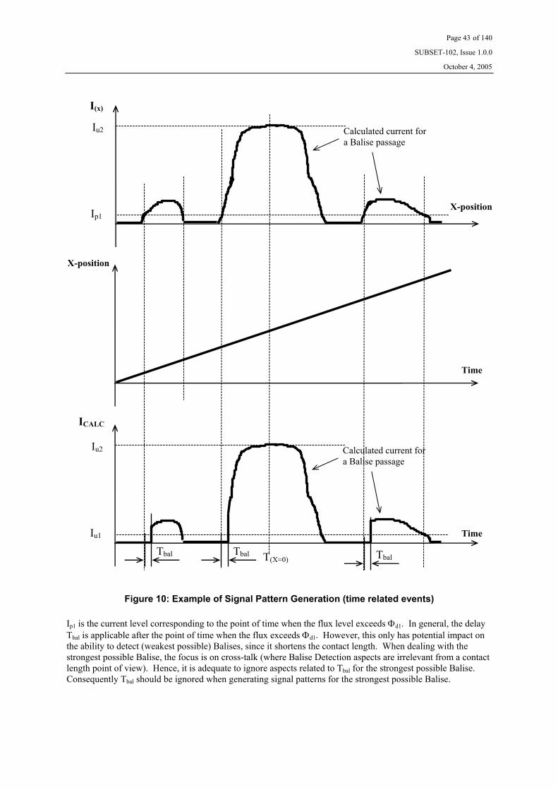
Page 43 of 140
SUBSET-102, Issue 1.0.0
October 4, 2005
Figure 10: Example of Signal Pattern Generation (time related events)
Ip1 is the current level corresponding to the point of time when the flux level exceeds Φd1. In general, the delay Tbal is applicable after the point of time when the flux exceeds Φd1. However, this only has potential impact on the ability to detect (weakest possible) Balises, since it shortens the contact length. When dealing with the strongest possible Balise, the focus is on cross-talk (where Balise Detection aspects are irrelevant from a contact length point of view). Hence, it is adequate to ignore aspects related to Tbal for the strongest possible Balise. Consequently Tbal should be ignored when generating signal patterns for the strongest possible Balise.
ICALC
Time
Tbal
Ip1
Iu2
I(x)
X-position
Calculated current for a Balise passage
X-position
Time
Iu1
Iu2 Calculated current for a Balise passage
Tbal Tbal T(X=0)

Page 44 of 140
SUBSET-102, Issue 1.0.0
October 4, 2005
4.2.6.3.3 Example of Algorithm for Signal Pattern Generation
Figure 11: Algorithm for Signal Pattern Generation, weakest Balise
Please note that it is the principle that is shown in Figure 11 only, and that the algorithm deals with the position related events illustrated in Figure 9 only. Also margins for variations over temperature and possible depend-ency for various test patterns must be considered (see section 4.2.6.3.1 on page 40). Units are indicated to the right of the figure.
2dΦ≥Φ
Start ([X=0,Y=0,Z=max])
Yes No
[dB]
[dB]
[dBIu1]
[dBIu1]
[mA]
0=Iδ 2
log20d
I ΦΦ
⋅=δ
1
2log20u
uILOW I
II ⋅+= δ
THREF
TH
IIlog20 ⋅=δ
δ−= LOWx II )(
201)(
)(
10:xI
ux II ⋅=
positionnext

Page 45 of 140
SUBSET-102, Issue 1.0.0
October 4, 2005
Figure 12: Algorithm for Signal Pattern Generation, strongest Balise
Please note that it is the principle that is shown in Figure 12 only, and that the algorithm deals with the position related events illustrated in Figure 9 only. Also margins for variations over temperature and possible depend-ency for various test patterns must be considered (see section 4.2.6.3.1 on page 40). Units are indicated to the right of the figure.
3dΦ≥Φ
Start ([X=0,Y=0,Z=max])
Yes No
[dB]
[dB]
[dBIu1]
[dBIu1]
[mA]
0=Iδ
3
log20d
I ΦΦ
⋅=δ
1
3log20u
uIHIGH I
II ⋅+= δ
THREF
TH
IIlog20 ⋅=δ
δ−= HIGHx II )(
201)(
)(
10:xI
ux II ⋅=
positionnext

Page 46 of 140
SUBSET-102, Issue 1.0.0
October 4, 2005
4.2.6.4 Transmission Tests
4.2.6.4.1 General Description, Transmission Tests
The purpose of this test is to determine the capability of the Antenna Unit - BTM function combination with respect to transmission of data enabling Balise Detection, reliable data transmission, side lobe management, and location accuracy during simulated dynamic conditions. It also serves as a test of system dynamics (strongest and weakest possible signals will occur during the test).
Criteria for sufficient transmission with respect to safety (Balise Detect) and availability (Telegram Decoding) are defined in UNISIG SUBSET-100 (certain system specific requirements on the minimum number of transmit-ted bits).
The input signal to the Reference Loop generating the Up-link signal shall be in accordance with results from section 4.2.6.3 on page 40. The time scale shall be selected in order to comply with speeds at each 50 km/h from 20 km/h up to the maximum specified velocity for the lateral deviation (Y position) to be simulated. The odometer input signal shall be selected accordingly.
For each simulated case (simulating various lateral deviations and vertical heights), the BTM function output signal shall be observed and evaluated via Interface ‘VK’. The BTM function shall be set in the normal opera-tional mode.
The criteria for the Antenna Unit - BTM function being able to correctly handle a certain sequence is that the BTM function transmits the required amount of bits (both ‘Data for Balise Detection’ and ‘Data for Telegram Decoding’ shall be evaluated).
In order to evaluate the correctness of when transmission occurred, the Balise simulations should be accurately allocated (at an exact distance from a chosen reference point) in a “virtual test line” used for each test sequence. The evolution of each sequence will be controlled by the Laboratory Test Management System (the LTMS). The LTMS will off-line scale each position based Balise pattern into a sequence of time based patterns accord-ing to the desired Balise “positions” and to the chosen train speed (see Figure 10 on page 43). After this, the LTMS down-loads all the relevant data to the arbitrary generator (RSG), and finally looks at the real-time odometer data coming from the LTOM. The LTOM issues a triggering pulse for the arbitrary generator when the odometer information of each Balise starting is reached. The positions of the transmission from the BTM function will be checked against the reference position of the simulated sequence. Additionally, the RSG shall provide a trigger to item the Interface ‘VK’ adapter indicating start of a ‘zero’ ASK bit, and the BTM function shall provide a trigger to the RSG synchronising ASK bit generation with the Tele-powering modulation pulses.
All Test Conditions according to section 4.1.4 on page 19 shall be considered. Certain tailoring is defined by chapter A3 of Annex A on page 111.
The present tests are performed with the antenna located in the reference position and in nominal environmental conditions. The applicable specific test conditions are simulated by using the radiation diagrams corresponding to such real conditions.

Page 47 of 140
SUBSET-102, Issue 1.0.0
October 4, 2005
4.2.6.4.2 Test Procedure, Transmission Tests
The test set-up in accordance with section 4.1.2 on page 15 applies. Steps 1 through 5 below constitute calibra-tion of the level of the generated Up-link signal for the test case in consideration. Succeeding steps form the actual test procedure.
1. For each individual test case (of those listed in chapters A1, A3 and section 4.1.4.2), calculate the posi-tion related pattern exemplified in Figure 9 on page 42 (thus obtaining I(x)) using the radiation pattern data obtained in section 4.2.6.2.2, properly scaled to the reference position used for the Antenna Unit un-der test. Thereafter, calculate the time related pattern for weakest Balise passage, using the equation of section 4.2.6.3.1 on page 40, and exemplified in Figure 10 on page 43 (thus obtaining ICALC). For the purpose of the latter calculation, a speed of 26 km/h shall be applied.
2. Position the Antenna Unit at a position corresponding to X = 0, Y = 0, and at maximum height defined by the Antenna Unit supplier (i.e., the same reference position used for the evaluation of the radiation dia-grams). Set the BTM function in “normal toggling operational mode”, and use nominal test conditions (see section 4.1.4.1 on page 19).
3. Set the RF switch in position P1 (enabling generation of Up-link signals).
4. Set the time and odometer input data (provided by the LTOM) to comply with the required speed of 26 km/h. Please note that there might be system-related properties setting certain limitations on proper-ties such as acceleration etceteras.
5. Set the arbitrary generator to generate a nominal ASK Up-link signal and apply the time related pattern obtained from step 1 above. Adjust the output level from the RSG_1 (by means of subsequent Balise passage simulations) such that the correct level (within ±0.3 dB) is obtained at the below defined two points. The current is measured by the oscilloscope, and the related transfer response of the Current Sense balun is in accordance UNISIG SUBSET-085. Please observe that the current measured by the os-cilloscope needs to be compensated for the B-factor of the Reference Loop (i.e., the measured target cur-rent shall be the desired Reference Loop current divided by B). Please observe also the definitions of UNISIG SUBSET-100 for the definition of the signal level. The level of the up-link pattern shall be checked at the following points:
• The position in time where the peak current in the calculated pattern occurs.
• The position in time closest to where the current exceeds the receiver threshold (measured at the reference position of the Antenna Unit) by 1 dB (but never lower than 0.5 dB above the threshold). The first position in time after the centre of the main lobe should be selected for this purpose.
In case there are problems fulfilling the target for both positions, the position close to the threshold has priority. In case not fulfilling both targets, this observation shall be recorded in the test record, and it shall be made clear that this is a test set-up imperfection. 1 2
6. Re-calculate the time based pattern to be used for testing according to the equation of section 4.2.6.3.1 on page 40, according to the example in Figure 10 on page 43 (ICALC), and using one applicable velocity de-fined by section 4.2.6.3.1 on page 40.
1 It is also important to verify, off-line, that the Tele-powering signal does not influence the actual Up-link
signal driven through the Reference Loop. 2 This check needs to be performed for the reference position only. The purpose is to identify potential test
set-up imperfections.
Page 48 of 140
SUBSET-102, Issue 1.0.0
October 4, 2005
7. Set the time and odometer input data (provided by the LTOM) to comply with the desired speed (to be defined by the manufacturer of the BTM function and defined by section 4.2.6.3.1 on page 40). Please note that there might be system related properties setting certain limitations on properties such as accel-eration etceteras.
8. Perform a sequence of at least 10 subsequent sweeps with the data determined above and record the output from the BTM function (via Interface ‘VK’), together with the reference location data provided by the LTOM. Measure, by the oscilloscope, and record also the value of the up-link current peak at each Balise passage simulation, evidencing the occurrence of cases of peak values slightly out of tolerance, possibly due to drifts of the RSG_1.3
9. Repeat steps 6 through 8 for all remaining applicable velocities defined by section 4.2.6.3.1 on page 40.
10. Repeat steps 1 through 9 or 6 through 9 (as appropriate) for all remaining combinations of longitudinal ranges, lateral displacements and heights (as defined by the Antenna Unit supplier) using the cases de-fined in chapter A1, on page 109 and chapter A3 on page 111. Please note that the physical location of the Antenna Unit and the Reference Loop shall not be changed.
11. Repeat steps 1 through 9 or 6 through 9 (as appropriate) for all remaining specific test conditions defined by section 4.1.4.2 on page 21 and chapter A3 on page 111. Please note that the physical location of the Antenna Unit and the Reference Loop shall not be changed, and that no debris or metallic objects shall be present (the influence of such conditions is included in the data from the radiation pattern this is the basis for the calculation of the signal pattern).
4.2.6.4.3 Acceptance Criteria, Transmission Tests
The criterion is that the BTM function is able to correctly receive a Balise during the simulated sequence and transmit the information via Interface ‘K’. This means that the following properties are correctly reported:
a. Data for Balise Detection during a sufficient period (as defined by SUBSET-100)
b. Correct data for Telegram Decoding during a sufficient period (as defined by SUBSET-100)
c. No report of ERTMS Unavailability data
d. No report of Eurobalise Reception data
e. Correct Link Test Data
f. Correct Antenna/BTM ID Data
g. Correct Link ID Data
h. Correct Bit Counter Data
i. Correct CRC
j. Correct Signal Strength Data (if available)
Transmission of a number of bits sufficient for creating a Balise Detect outside a Balise passage simulation (considering all relevant delays) shall be regarded as a failure condition.
3 The measurement is performed within a time window corresponding to about 20 mm at the current test speed.

Page 49 of 140
SUBSET-102, Issue 1.0.0
October 4, 2005
4.2.6.5 Electrical Tele-powering Characteristics
This is included in the verifications according to UNISIG SUBSET-085.
4.2.6.6 Maximum Flux Level
4.2.6.6.1 General Description, Maximum Flux Level
The purpose of this test is to systematically evaluate the performance of the Tele-powering signal generated by the Antenna Unit - BTM function combination. The maximum flux generated through a Reference Loop is subject to testing.
The output signal shall be evaluated during static conditions in toggling Tele-powering mode. The output signal shall be measured using a Reference Loop. The Reference Loop should be subjected to various load conditions during maximum flux measurements.
The BTM function shall be forced to the applicable mode using suitable commands inserted via Interface V1.
Geometrical test points and applicable test conditions are defined by sections A4.1 on page 112 and A4.2 on page 112.
The maximum flux level test shall determine the flux level through the Reference Loop under various load con-ditions, and for various geometrical test points. The different load conditions shall be tailored to simulate worst case conditions as defined by UNISIG SUBSET-100. Geometrical test points are defined by section A4.2 on page 112.
4.2.6.6.2 Specific Test Set-up for Maximum Flux Level verification
The test set-up is shown in Figure 13 below. Annex E on page 134 gives an example of suitable test equipment.
10.
PPM1
Reference Loop 7.
BTMfunction
Antenna Unit
Interface A
Interface ‘V1’
Current Sense Balun
PowerMeter 1
Load
Interface ‘V1’Adapter
34.
Laboratory TestManagement
System
38.
14.
Figure 13: Test set-up for Maximum Flux Level Tests
Item 10, is computer controlled via the Laboratory Test Management System (the computer control is intention-ally not indicated in the figure).

Page 50 of 140
SUBSET-102, Issue 1.0.0
October 4, 2005
4.2.6.6.3 Test Procedure, Maximum Flux Level
The test set-up in accordance with section 4.2.6.6.2 on page 49 applies.
1. Connect the equipment as defined by section 4.2.6.6.2 on page 49, and ensure that the Current Sense balun is calibrated as defined by UNISIG SUBSET-085.
2. Connect a load to the Reference Loop forming a total impedance in the circuit simulating worst case con-ditions as defined by UNISIG SUBSET-100 (i.e., the sum of the Reference Loop impedance and the ex-ternal load and the Current Sense balun shall constitute conditions as defined by UNISIG SUBSET-100).
3. Position the Antenna Unit in the geometrical test point [X = 0, Y = 0, Z = minimum height].
4. Command the BTM function to its normal operational mode regarding toggling Tele-powering, or to any other mode equivalent to this (from the point of view of the maximum flux level evaluation).
5. Record the power level of power meter 1 (PPM1).
6. Calculate the flux through the Reference Loop using the following equation:
( )27A
loopload1PM
f2Zk
ZZBP
⋅π⋅⋅⋅
+⋅⋅=Φ
where: PPM1 is power in Watt recorded by power meter 1 B is the Reference Loop transfer matching ratio Zloop is the actual impedance of the Reference Loop in the absence of any antenna Zload is the external load impedance connected to the Reference Loop f27 is the Tele-powering frequency (27.095 MHz) k is the calibration factor determined by UNISIG SUBSET-085 ZA is defined in UNISIG SUBSET-085
7. Perform steps 5 and 6 for all the other geometrical test points defined by section A4.2 on page 112.
8. Repeat steps 2 through 7 for all applicable worst case load conditions.
Please observe that the actual load values defined in this test procedure constitute the total load of the circuit. This means that a certain load defined above is the sum of the external load connected to the Reference Loop, the influence of the Current Sense balun, and the actual Reference Loop impedance. Hence, the Reference Loop impedance has to be measured separately, and the impedance of the combination of the Current Sense balun and the external load has to be measured separately, and the total impedance has to be calculated. This has to be characterised prior to the test.
4.2.6.6.4 Acceptance Criteria, Maximum Flux Level
The requirement is that the flux level never exceeds φd4.

Page 51 of 140
SUBSET-102, Issue 1.0.0
October 4, 2005
4.2.6.7 Up-link Characteristics
4.2.6.7.1 General Description, Up-link characteristics
The purpose of this test is to systematically evaluate the BTM function capability with respect to extremes of the electrical characteristics of the Up-link signal (such as carrier frequency, tpudelay, t50, and amplitude jitter). Suit-able test patterns shall be generated by the arbitrary generator (RSG) in order to test the properties mentioned above.
The input signal to the Reference Loop generating the Up-link signal shall be an ASK signal with “imperfec-tions” as described above. Furthermore, an additional modulation in accordance with section 4.2.6.3 on page 40 shall be present in order to simulate a Balise passage. Test data from sections 4.2.6.2 on page 36 and 4.2.6.3 on page 40 shall be used for creation of the simulated Balise passage. The BTM function shall be set to normal operational mode.
Only a limited amount of combinations of lateral deviation and vertical height will be considered (see section A4.2 on page 112). The BTM function output signal shall be observed via Interface VK and evaluated.
The criteria for the Antenna Unit and BTM function being able to correctly handle certain sequence are defined in section 4.2.6.4.3 on page 48.
Test Conditions shall be in accordance with section A4.1 on page 112.
4.2.6.7.2 Test Procedure, Electrical Up-link Characteristics
The test set-up in accordance with section 4.1.2 on page 15 applies.
Suitable test patterns for the arbitrary generator (RSG) shall be developed that simulate the following extremes of the Up-link signal:
• Carrier frequency = 4.0 MHz and 4.7 MHz.
• tpudelay = 0.6 µs and 1.65 µs.
• t50 = 2 µs and 5 µs.
• Amplitude Jitter = ±1.0 dB.
The envelope of the pulse shall be approximately exponentially decreasing. See Figure 6 on page 20.
One main aspect as listed above shall be evaluated at a time. Start-up and steady state behaviour shall be con-sidered where applicable. For the purpose of selection ‘R3’ defined in section A4.2 on page 112, simulation of weakest Balise (ILOW) shall apply, and for the purpose of selection ‘R5’, simulation of strongest Balise (IHIGH) shall apply. Please observe the definitions of UNISIG SUBSET-100 for the definition of the signal level.
Apart from these modifications of the ASK signal and the selection of geometrical test points and test condi-tions, the test procedure is identical to the procedure defined in section 4.2.6.4.2 on page 47 (Transmission Tests).
Geometrical test points and test conditions are defined by chapter A4.1 on page 112, and chapter A4.2 on page 112.
4.2.6.7.3 Acceptance Criteria, Electrical Up-link Characteristics
See section 4.2.6.4.3 on page 48.

Page 52 of 140
SUBSET-102, Issue 1.0.0
October 4, 2005
4.2.6.8 Cross-talk Immunity
4.2.6.8.1 General Description, Cross-talk Immunity
Cross-talk tests shall determine whether there are any potential cross-talk situations within the defined geometri-cal region and during the test conditions defined by section 4.1.4 on page 19. Where applicable, certain cross-talk margins should be evaluated. Specific cable related cross-talk is not included in this section, but separately dealt with in 4.2.6.9 on page 55.
The Tele-powering flux shall be measured using a Reference Loop. The recorded flux level (φ) shall after this be used for determining the response from a strongest worst case Balise (IHIGH) utilising the upper limits of the transfer response curve defined by UNISIG SUBSET-100. Thereafter, the Reference Loop shall be connected to a signal generator generating an ASK Up-link signal that simulates a representative Balise passage (see Figure 8 on page 36), and carrying an ‘all zero’ sequence with a peak current level as determined above (IHIGH). The BTM function output response shall be observed via Interface ‘VK’. The requirement is that there is no trans-mission of bits sufficient for creating a Balise Detect. Thereafter, the peak current level shall be gradually in-creased until Balise detection is possible, or until a peak current value of Iu3 +20 dB is reached. The procedure is similar to the method described in section 4.2.6.2.1 on page 36. The difference is that current levels up to the maximum peak current level Iu3 +20 dB are quantitatively tested to evaluate the margin for cross-talk.
This procedure shall be performed for all the geometrical positions defined by chapter A2 on page 110, and for all test conditions defined by section 4.1.4 on page 19. Certain tailoring is defined by chapter A3 on page 111.

Page 53 of 140
SUBSET-102, Issue 1.0.0
October 4, 2005
4.2.6.8.2 Test Procedure, Cross-talk Immunity
The test set-up in accordance with section 4.1.2 on page 15 applies.
1. Position the Antenna Unit in the first geometrical test point defined by chapter A2 on page 110 and select nominal test conditions defined by section 4.1.4.1 on page 19.
2. Set the RF switches in positions P2 and P3 (thus connecting the power meter 2).
3. Command the BTM function to its normal operational mode regarding toggling Tele-powering, or to any other mode equivalent to this (from the point of view of the Cross-talk evaluation).
4. Record the value of power meter 2.
5. Repeat step 4 for all remaining geometrical test points defined by chapter A2 on page 110 and chapter A3 on page 111.
6. Calculate the flux for all geometrical test points using the equation defined in section 4.2.6.2.2 on page 38.
7. Determine the corresponding worst case (strongest) response from the Balise (IHIGH) as described in sec-tion 4.2.6.8.1 on page 52.
8. Set the RF switch in position P1 (thus enabling generation of Up-link signals).
9. Set the arbitrary generator to generate an Up-link signal in accordance with Figure 8 on page 36. The initial current setting shall be the Iu3 current. The current is measured by the oscilloscope, and the related transfer response of the Current Sense balun is in accordance with UNISIG SUBSET-085. Please ob-serve that the current measured by the oscilloscope needs to be compensated for the B-factor of the Ref-erence Loop (i.e., the measured target current shall be the desired Reference Loop current divided by B). Please observe also the definitions of UNISIG SUBSET-100 for the definition of the signal level. Set the time and odometer information to comply with a speed of 100 km/h.
10. Position the Antenna Unit in the first geometrical test point defined by chapter A2 on page 110 and select nominal test conditions defined by section 4.1.4.1 on page 19.
11. Record the output from the BTM function (via Interface ‘VK’) and determine whether Balise detection is possible or not. That is, no transmission of sufficient amount of bits in accordance with UNISIG SUBSET-100.
12. In case that Balise detect was not possible, increase the peak current level in steps of 0.5 dB until Balise detect becomes possible, or until Iu3 + 20 dB is reached. Repeat steps 11 and 12 until the margin is de-termined.
13. Repeat steps 11 and 12 for all remaining geometrical test points defined by chapter A2 on page 110 and chapter A3 on page 111, using the appropriate IHIGH for each separate point.
14. Repeat steps 1 through 13 for all specific test conditions defined by section 4.1.4.2 on page 21 and chap-ter A3 on page 111. Please observe that “nominal conditions” of step 1 is substituted by the relevant “specific condition” for each subsequent pass.
It must be verified that reliable Up-link measurements can be performed in the presence of the applicable 27 MHz Tele-powering signal.

Page 54 of 140
SUBSET-102, Issue 1.0.0
October 4, 2005
4.2.6.8.3 Acceptance Criteria, Cross-talk Immunity
4.2.6.8.3.1 General
The requirement is that no cross-talk occurs. There is no explicit requirement on a certain margin, but the de-fined test procedure makes it possible to perform this evaluation. The evaluation of the cross-talk margin must be separated into the two cases defined by UNISIG SUBSET-100.
4.2.6.8.3.2 One Balise and one Antenna Unit
This case is applicable for lateral deviations of 1400 mm or more.
The cross-talk margin in dB is evaluated as follows:
ΦΦ
⋅+⋅=Φ≤Φ= 3
33 log20log20arg d
u
CTd I
IinM
3
3 log20argu
CTd I
IinM ⋅=Φ>Φ=
Where: φ is the actual flux level in nVs for the geometrical position in question φd3 is in nVs, and defined by the transfer characteristics of the Balise ICT is the actual current in mA for when cross-talk occurs Iu3 is in mA, and defined by the transfer characteristics of the Balise Margin is the cross-talk margin in dB
4.2.6.8.3.3 One Balise and two Antenna Units
This case is applicable for lateral deviations of 3000 mm or more, and for longitudinal deviations as defined by the manufacturer of the Antenna Unit.
The cross-talk margin in dB is evaluated as follows:
3
log20argu
CT
II
inM ⋅=
Where: ICT is the actual current in mA for when cross-talk occurs Iu3 is in mA, and defined by the transfer characteristics of the Balise Margin is the cross-talk margin in dB

Page 55 of 140
SUBSET-102, Issue 1.0.0
October 4, 2005
4.2.6.9 Cross-talk Immunity with Cables
4.2.6.9.1 General Description, Cross-talk Immunity with Cables
This section defines measurement methods for verifying potential cable related cross talk for the Antenna Unit. This includes testing Up-Link Cross talk from cable to Antenna.
4.2.6.9.2 Specific Test Configuration, Up-Link Cross-talk from cable to Antenna Unit
A proposed test set-up is shown in Figure 14 below. Annex E on page 134 gives an example of suitable test equipment. See also section 4.1.3 on page 17.
Antenna
z-axis
500
I R2
600 600
I
E
500
x-axis
y-axis
z-axis
32.
37.
PM1
12. Filter
Antenna
R1
13.
2.
3.
4.
4.5 MHz
BTM function
VTH (yes or no)
D Minimum height (for the Antenna Type in question)
Top of Rail (fictive)
20. Balun
Attenuator
Attenuator
Signal Generator
RF Amplifier
Oscillocsope
35
40
8
Metallic Bar Profile
Filter 45.
Figure 14: Up-link Test Configuration, cable to Antenna Unit

Page 56 of 140
SUBSET-102, Issue 1.0.0
October 4, 2005
4.2.6.9.3 Test Procedure, Up-link Cross-talk from cable to Antenna Unit
The test set-up shown in Figure 14 on page 55 shall be used. The resistor R1 shall be 350 Ω and R2 shall be 400 Ω. The distance D is the position in the x direction, and shall be in the range from –1000 mm to 1000 mm. This test determines the signal received in an Antenna induced from a cable with the current 2 mA and 10 mA for E = 93 mm and E = 400 mm respectively. See Figure 14 on page 55 for definition of E.
1. Position the Antenna at position D = -1000 mm and E = 93 mm and set the BTM function in normal operational mode.
2. Set the Signal Generator to generate a 4.5 MHz ASK Up-link signal carrying an ‘all zero’ sequence, and the current ‘I’ to 2 mA. For the suggested current probe, a current of 1 mA will give a voltage of 1 mV into 50 Ω. The definitions of UNISIG SUBSET-100 shall be used for the definition of the signal level.
3. Verify that the response from the Antenna Unit is below Vth by observing output data via Interface ‘VK’ (i.e., no transmission of sufficient amount of ‘Data for Balise Detection’ bits in accordance with UNISIG SUBSET-100).
4. Position the Antenna at regular intervals of +40 mm, up to the distance D = 1000 mm. For each posi-tion, verify that the response is below Vth.
5. Position the Antenna at position D = -1000 mm and E = 400 mm.
6. Set the Signal Generator to generate a 4.5 MHz ASK Up-link signal carrying an ‘all zero’ sequence, and the current ‘I’ to 10 mA.
7. Verify that the response from the Antenna Unit is below Vth by observing output data via Interface ‘VK’ (i.e., no transmission of sufficient amount of ‘Data for Balise Detection’ bits in accordance with UNISIG SUBSET-100).
8. Position the Antenna at regular intervals of +40 mm, up to the distance D = 1000 mm. For each posi-tion, verify that the response is below Vth.
4.2.6.9.4 Acceptance Criteria, Cross-talk Immunity with Cables
The response from the Antenna Unit shall be below Vth (i.e., no response sufficient for making the BTM func-tion able to create the amount of ‘Data for Balise Detection’ bits in accordance with UNISIG SUBSET-100).
4.2.6.10 Balise Detect Ability Supervision
This is included in the verifications according to UNISIG SUBSET-085.
Page 57 of 140
SUBSET-102, Issue 1.0.0
October 4, 2005
4.3 Laboratory Tests, Alternative 2 Interface
4.3.1 Electrical Data
See section 4.2.1 on page 25.
4.3.2 Data Transmission
4.3.2.1 General Description, Data Transmission
This section defines the test procedure for verifying the data transmission. The test procedure includes verifica-tion of the following properties:
• Presence of Data signal
• Presence of CLK signal
4.3.2.2 Test Pattern, Data Transmission
The RSG shall be programmed such that a repetitive 00001110101 ASK bit pattern is continuously transmitted through the air gap (Interface ‘G’).
4.3.2.3 Test Procedure, Data Transmission
1. Position the antenna such that the manufacturer dependent nominal vertical distance is obtained with respect to the Reference Loop, and that X=0 and Y=0 with respect to the Reference Loop.
2. Adjust the output level from the RSG such that an Up-link current of Iu1 +3 dB is obtained. Please ob-serve that the Up-link current must be modulated as defined in Figure 8 on page 36.
3. Temporarily connect the oscilloscope to Interface ‘K’. Please observe that a floating measurement shall be performed (e.g., using two channels and performing a differential measurement). The oscillo-scope should be triggered from the output of the RSG.
4. Record the resulting transmission of at least one repetition of the defined pattern.
5. Verify the existence of Data signal.
6. Verify the existence of CLK signal.
4.3.2.4 Acceptance Criteria, Data Transmission
a. The test shall verify the existence of Data signal as specified in UNISIG SUBSET-101.
b. The test shall verify the existence of CLK signal as specified in UNISIG SUBSET-101.

Page 58 of 140
SUBSET-102, Issue 1.0.0
October 4, 2005
4.3.3 Timing Requirements
4.3.3.1 General Description, Timing Requirements
This section defines the test procedure for verifying the timing requirements. The test procedure includes verifi-cation of the following properties:
• Correctness of 50 kHz ASK bit data rate
• Correctness of phase position between various channels (if more than one is implemented)
• Correctness of the relation between the Data and CLK signals
• Propagation delay from Interface ‘G’ to Interface ‘K’
4.3.3.2 Test Pattern, Timing Requirements
The RSG shall be programmed such that a repeated 40 ASK bit pattern starting with 8 consecutive ‘zeros’ fol-lowed by 8 consecutive ‘ones’, and finally followed by toggling ‘zeros’ and ‘ones’ up to the end of the of the pattern is continuously transmitted through the air gap (Interface ‘G’).
4.3.3.3 Test Procedure, Timing Requirements
1. Position the antenna such that the manufacturer dependent nominal vertical distance is obtained with respect to the Reference Loop, and that X=0 and Y=0 with respect to the Reference Loop.
2. Adjust the output level from the RSG such that an Up-link current of Iu2 is obtained. Please observe that the Up-link current must be modulated as defined in Figure 8 on page 36.
3. Temporarily connect the oscilloscope to Interface ‘K’. Please observe that a floating measurement shall be performed (e.g., using two channels and performing a differential measurement). The oscillo-scope should be triggered from the output of the RSG.
4. Record the resulting transmission of at least one full bit pattern repetition in the air gap.
5. Evaluate the 50 kHz ASK bit data rate.
6. In case more than one channel is implemented, measure the phase position between various channels.
7. Evaluate the phase position between the positive edge of the CLK signal and the Data signal, and the length of the CLK signal.
8. Evaluate the propagation delay between the air gap signal and the data transmitted through Inter-face ‘K’.
4.3.3.4 Acceptance Criteria, Timing Requirements
a. The ASK bit data rate shall be 50 kbits/s within the tolerance specified in UNISIG SUBSET-100.
b. The phase difference between the various channels (if more than one is implemented) shall be less than what is specified in UNISIG SUBSET-101.
c. The phase position between the positive edge of the CLK signal and the Data signal, and the length of the CLK signal shall comply with the definitions of UNISIG SUBSET-101.
d. The propagation delay shall be less than what is specified in UNISIG SUBSET-101.
Data shall not be evaluated in case a forced link test occurs.

Page 59 of 140
SUBSET-102, Issue 1.0.0
October 4, 2005
4.3.4 Functional Data
4.3.4.1 General Description, Functional Data
This section defines the test procedure for verifying the correct transmission of data from a functional perspec-tive. The test procedure includes verification of the following properties:
• Transmission of Data
• Handling of Tele-powering being switched off
• Handling of Eurobalise (FSK) signals
• Transmission of link tests
In case multiple channels are implemented, the requirements related to diversified data defined in UNISIG SUBSET-101 will also be verified from a transmitter perspective. Finally, simulation of a permanently failing BTM functionality is also simulated.
4.3.4.2 Test Patterns, Functional Data
See section 4.2.4.2 on page 28.
4.3.4.3 Test Procedure, Functional Data
See section 4.2.4.3 on page 29.
4.3.4.4 Acceptance Criteria, Functional Data
For each of the acquisitions performed in steps 3 and 5, it shall be verified that:
a. Data complies with, and is consistently synchronised with, the air gap signal.
For the acquisitions performed in step 9, it shall be verified that:
b. The CLK signal is at constant polarity as stated in UNISIG SUBSET-101.
For the acquisition performed in step 11, it shall be verified that:
c. Data and CLK signals comply with the requirements of UNISIG SUBSET-101 defined for “Eurobalise mode”.
For the acquisition performed in step 15, it shall be verified that:
d. The interface ‘K’ channel activity is terminated after the introduction of the failure condition.
For the acquisition performed in step 13, it shall be verified that:
e. Link check patterns are transmitted in accordance with the requirements of UNISIG SUBSET-101.
Specifically for step 18 (if applicable), aspects on diversified data shall be considered. See requirements in UNISIG SUBSET-101.

Page 60 of 140
SUBSET-102, Issue 1.0.0
October 4, 2005
4.3.5 Link Check Functionality
4.3.5.1 General Description, Link Check Functionality
This section defines the test procedure for verifying the correct transmission of signals used for on-line supervi-sion of the Interface ‘K’ link. The test procedure includes verification of the following properties:
• Time between transmissions of link check patterns
• Correctness of link check pattern
• Blocking of link checks during reception of Balise data
4.3.5.2 Test Pattern, Link Check Functionality
See section 4.2.5.2 on page 32.
4.3.5.3 Test Procedure, Link Check Functionality
See section 4.2.5.3 on page 32.
4.3.5.4 Acceptance Criteria, Link Check Functionality
For the acquisition performed up to step 3, it shall be verified that the link test pattern defined in UNISIG SUBSET-101 is transmitted.
For the acquisition performed up to step 3, it shall be verified that there is at least one approved link test within the defined sliding 500 ms time interval.
For the acquisition performed in step 5, it shall be verified that the following is transmitted for a period of time not exceeding 1 s:
a. Normal ASK data is transmitted via Interface ‘K’.
After a period of time greater than 0.5 s but not exceeding 1 s, it shall be verified that a link test is transmitted also in the presence of transmission of ASK Up-link data.
For the acquisition performed in step 7, it shall be verified that the following is transmitted for a period of time not exceeding 1 s:
b. Data and CLK signals comply with the requirements of UNISIG SUBSET-101 defined for “Eurobalise mode”.
After a period of time greater than 0.5 s but not exceeding 1 s, it shall be verified that a link test is transmitted also in the presence of transmission of FSK Up-link data.

Page 61 of 140
SUBSET-102, Issue 1.0.0
October 4, 2005
4.3.6 Verification of Transmission and Bit Stream Requirements
See section 4.2.6 on page 35.
The only modification applicable to this alternative 2 interface is that there is no distinguishing between ‘Data for Balise Detection’ and ‘Data for Telegram Decoding’ that is to be considered. There is only (safe) ‘Data’ in this interface, used for both Balise Detection and Telegram Decoding.
For the purpose of Transmission Test acceptance criteria (see section 4.2.6.4.3 on page 48, the following ap-plies:
• Data is present during a sufficient period (as defined by UNISIG SUBSET-100)
• Data in Interface ‘K’ complies with the data transmitted in Interface ‘G’
4.4 Requirements for Test Tools
See UNISIG SUBSET-085, and applicable annexes herein.

Page 62 of 140
SUBSET-102, Issue 1.0.0
October 4, 2005
5 Tests of the STM
5.1 Reference Test Configuration
5.1.1 General
In order to observe the reaction of the STM upon introduction of abnormal conditions in the Interface ‘K’ data, company specific sequences shall be executed and the reaction of the STM shall be observed via the STM FFFIS.
5.1.2 Generic Test Set-up
The recommended general test set-up is shown in Figure 15 below. Annex E on page 134 gives an example of suitable test equipment.
I/F ’K’
STMSTM/ETCS FFFIS STMSIMULATOR
STMS
FFFIS
DATA EXCHANGE
SCENARIOCONTROLLER
SC
MODULE EVENT RECORDERMER
SCENARIOGENERATOR
SG
TRIP ANALYSIS &VALIDATION
TAV
TRAIN MOTIONSIMULATOR
TMS
Equipment to be tested
Laboratory ModulesProfibusAnalyser
TIU/BIUADAPTOR
SPEED SENSORADAPTOR
TIUSIMULATOR
TIUS
SPEED SENSOR SIMULATOR
SSS
Interface Adaptors
Optional Interfaces for direct access to the brakes and odometer
Interface ‘K’ Adapter
PC
Modules specific for Interface ‘K’ testing
46
Figure 15: Generic Test set-up for STM tests

Page 63 of 140
SUBSET-102, Issue 1.0.0
October 4, 2005
5.1.3 Generic Notes
1. The possible need for system specific start-up sequences in order to ensure defined state/mode of the STM is not dealt with in this specification.
2. The test set-up shown in Figure 15 on page 62 in general includes the entire test environment used for testing the STM functionality. This is defined by the UNISIG STM group and included in UNISIG SUBSET-074-1. Some modules are highlighted as “specific for Interface ‘K’ testing. These are re-quired for enabling testing of the Interface ‘K’ functionality, are defined within this specification (SUBSET-102). The general STM test environment is not further dealt with in this specification.

Page 64 of 140
SUBSET-102, Issue 1.0.0
October 4, 2005
5.1.4 Test Conditions
5.1.4.1 General
The nominal conditions defined in this section apply to all measurements unless otherwise explicitly stated.
5.1.4.2 Climatic Conditions
Ambient temperature: 25 °C ± 10 °C.
Relative humidity: 25 % to 75 %.
Atmospheric Pressure: 86 kPa to 106 kPa.
5.1.4.3 RS 485 Conditions
Nominal RS 485 conditions apply unless otherwise explicitly stated. The ASK data bit rate shall be the nominal data rate defined by UNISIG SUBSET-101. Likewise, for the alternative 1 interface, the Bi Phase Level (BPL) clock shall be set to its nominal behaviour defined by UNISIG SUBSET-101.
5.1.4.4 Time and Odometer Conditions
For the purpose of the STM tests defined herein, the velocity 100 km/h shall be used unless nothing else is specified.
5.1.4.5 Test Sequences and Telegram Content
In general, the details for the various sequences (such as suitable Balise messages, configuration of Balise Groups, etc.) are KER system dependent. Suitable sequences shall be defined by each STM manufacturer in order to be able prove the various aspect defined herein (i.e., to be able to run a sequence, and to be able to record a known and defined reaction). Most likely, there is a need for a system specific start-up sequence before the actual test sequences are executed in order to ensure that the system is in a known state/mode. Also this shall be defined by the STM manufacturer. Where applicable, the expected STM reaction time shall be defined by the manufacturer.
The need for system specific start-up sequences is not further dealt with in this specification (i.e., not mentioned in the specific test procedures).
The actual telegram content is dependent on the specific test procedures herein, but also dependent on the spe-cific system in question. Further details related to what functionality is to be evaluated are defined in the various test procedures included in this chapter (chapter 5).
In general, the same data should simultaneously be transmitted at all involved channels (except the obvious differences in Link ID Data and CRC in the alternative 1 interface) unless explicitly otherwise defined.
When faulty signal is given to the STM over Interface 'K', the STM shall have an observable reaction within a defined time. The time is product specific, but shall not exceed the stipulated limit.
The observable reaction is product specific, but usable reactions are:
• The STM enters FA state
• The STM issues a Diagnostic message
• The STM gives specific indication to DMI (i.e., a text message about the failure condition)

Page 65 of 140
SUBSET-102, Issue 1.0.0
October 4, 2005
5.1.5 Test Tools and Procedures
The following list summarises the herein-defined STM tests:
1. Electrical data
2. Data transmission
3. Timing requirements
4. Functional data
5. Link check functionality
6. Handling of diversified data
7. Detection of Balises
8. Management of side lobe effects
9. Telegram decoding
The following specific tools are anticipated for the STM tests:
• Interface ‘K’ adapter • Interface ‘STM’ adapter
The Interface STM environment should for obvious reasons be available since it is anyway required for per-forming verification of the operational STM functionality. This device is specified on a functional basis by the STM group. Therefore this adapter is not within the scope of this specification. However, this test specification possibly demands some kind of synchronisation between the generation of certain sequences and the observation of the STM reaction. Such information should be communicated to the group in charge of specifying the Inter-face ‘STM’ adapter.
The Interface ‘K’ adapter is specifically required for enabling the execution of the tests defined herein. There-fore, this adapter is defined to a sufficient level of detail in order to facilitate designing such a tool. It should be observed that aspects on overall test time are crucial. A suitable block diagram is presented in Annex D herein.

Page 66 of 140
SUBSET-102, Issue 1.0.0
October 4, 2005
5.2 Laboratory Tests, Alternative 1 Interface
5.2.1 Electrical Data
5.2.1.1 General, Electrical Data
This section outlines the tests needed for ensuring that the electrical data for Interface ‘K’ is fulfilled.
Since it is likely that commercially available receiver circuits are used, it is in such a case sufficient to ensure (show guarantees) that the actual device fulfils the applicable standard. Specifically developed receiver circuits must be fully characterised in order to show compliance with the applicable standard.
The principle above also applies to ensuring the defined isolation requirements.
The receiver shall be verified through applying worst case conditions according to the RS 485 standard at the input terminal of the receiver.
5.2.1.2 Conditions, Electrical Data
The maximum amount of loading receivers and (non active) transmitters shall be considered. See definitions in UNISIG SUBSET-101.
5.2.1.3 Acceptance Criteria, Electrical Data
a. The limits defined by the RS 485 standard shall be fulfilled.
b. The isolation requirements defined by the EN 50155 standard shall be fulfilled.

Page 67 of 140
SUBSET-102, Issue 1.0.0
October 4, 2005
5.2.2 Data Transmission
Fulfilment of the basic requirements for ensuring correct data transmission is implicitly verified through the other tests of this chapter (chapter 5).
5.2.3 Timing Requirements
5.2.3.1 General Description, Timing Requirements
This section defines the test procedure for verifying the ability to cope with extreme timing requirements. The test procedures include verification of the following properties:
• Ability to cope with extreme ASK bit data rates
• Ability to cope with extreme phase difference between various channels
• Ability to cope with extreme jitter in the Bi Phase Level (BPL) clock generation
• Reaction on correct and incorrect number of stop bits
5.2.3.2 Test Pattern, Timing Requirements
The STM manufacturer shall define a suitable test sequence and test patterns such that correct handling of the imperfections in the parameters defined in section 5.2.3.1 is ensured.
If not explicitly otherwise defined, Link Test Data shall be transmitted on a regular basis according to UNISIG SUBSET-101 (i.e., link tests shall be performed in accordance with UNISIG SUBSET-101).

Page 68 of 140
SUBSET-102, Issue 1.0.0
October 4, 2005
5.2.3.3 Test Procedure, Timing Requirements
1. Transmit the system specific test sequence with the Bi Phase Level (BPL) clock and ASK bit data rates in Interface ‘K’ set to the nominal value as defined by UNISIG SUBSET-101.
2. Observe the reaction of the STM via the STM FFFIS.
3. Set the ASK bit data rate in Interface ‘K’ to the lower extreme defined by UNISIG SUBSET-101, and transmit the system specific test sequence.
4. Observe the reaction of the STM via the STM FFFIS.
5. Set the ASK bit data rate in Interface ‘K’ to the upper extreme defined by UNISIG SUBSET-101, and transmit the system specific test sequence.
6. Observe the reaction of the STM via the STM FFFIS.
7. Set the BPL clock data rate in Interface ‘K’ such that only 23 stop bits are generated within the avail-able 20 µs period, and transmit the system specific test sequence.
8. Observe the reaction of the STM via the STM FFFIS (including the reaction time).
9. Set the BPL clock data rate in Interface ‘K’ such that 27 stop bits are generated within the available 20 µs period, and transmit the system specific test sequence.
10. Observe the reaction of the STM via the STM FFFIS (including the reaction time).
11. Set the ASK bit data rate in Interface ‘K’ such that it is 50 % outside the lower tolerance in data rate as defined by UNISIG SUBSET-101, and transmit the system specific test sequence.
12. Observe the reaction of the STM via the STM FFFIS (including the reaction time).
13. Set the ASK bit data rate in Interface ‘K’ such that it is 50 % outside the upper tolerance in data rate as defined by UNISIG SUBSET-101, and transmit the system specific test sequence.
14. Observe the reaction of the STM via the STM FFFIS (including the reaction time).
15. Set the jitter in the Bi Phase Level (BPL) clock to the upper extreme defined by UNISIG SUBSET-101, and transmit the system specific test sequence.
16. Observe the reaction of the STM via the STM FFFIS.
The above steps shall be performed simultaneously transmitting the defined data rates at all channels. Further-more:
17. Simulate, as case one, the maximum allowed phase difference between channel a and channel b, and as case two, the maximum allowed phase difference between channel c and channel d as defined in UNISIG SUBSET-101.
18. Observe the reaction of the STM via the STM FFFIS.
5.2.3.4 Acceptance Criteria, Timing Requirements
For each of the steps 2, 4, 6, 16, and 18, it shall be verified that the STM continues to operate without loss of performance.
For each of the steps 8, 10, 12, and 14, verify that the manufacturer dependent reaction is obtained within the stipulated reaction time.

Page 69 of 140
SUBSET-102, Issue 1.0.0
October 4, 2005
5.2.4 Functional Data
5.2.4.1 General Description, Functional Data
This section defines the test procedure for verifying the correct reaction on data from a functional perspective. The test procedure includes verification of the following properties:
• Reaction on ‘Data for Balise Detection’ (BD) • Reaction on ‘Data for Telegram Decoding’ (TD) • Reaction on ‘ERTMS Unavailability’ (EU) • Reaction on ‘Eurobalise Reception’ (EB) upon reception of Eurobalises • Reaction on ‘Link Test Data’ (LT) • Reaction on ‘Signal Strength Data’ (S) • Reaction on ‘Antenna/BTM ID Data’ (A) • Reaction on ‘Link ID Data’ (L) • Reaction on ‘Bit Counter Data’ (B) • Reaction on incorrect CRC
The requirements related to diversified data defined in UNISIG SUBSET-101 will also be verified from a re-ceiver perspective. Finally, simulation of the Interface ‘K’ link set to inactive (no BPL coding), indicating per-manently failing BTM functionality, is also simulated in order to verify that the STM correctly copes with such a situation.
Definitions of the acronyms used herein are found in UNISIG SUBSET-101.
5.2.4.2 Test Pattern, Functional Data
The STM manufacturer shall define a suitable test sequence and test patterns such that the correct behaviour with respect to the data defined in section 5.2.4.1 is ensured.
If not explicitly otherwise defined, Link Test Data shall be transmitted on a regular basis according to UNISIG SUBSET-101 (i.e., link tests shall be performed in accordance with UNISIG SUBSET-101).
If otherwise not explicitly mentioned in the test procedure, it is assumed that a correctly operative sequence without imperfections is transmitted, where BD and TD data is identical. Deviations from this condition (e.g., introduction of failure conditions) are explicitly defined.

Page 70 of 140
SUBSET-102, Issue 1.0.0
October 4, 2005
5.2.4.3 Test Procedure, Functional Data
1. Transmit the correct sequence.
2. Observe the reaction of the STM via the STM FFFIS.
3. For at least one of the Balise passages, introduce differences between BD and TD data. The differ-ences shall be such that TD data is correct and that BD data still does not jeopardise the Balise Detect criteria (i.e., that there is a higher percentage of ‘zeros’ in BD data than in TD data).
4. Observe the reaction of the STM via the STM FFFIS.
5. For at least one of the Balise passages, introduce differences between BD and TD data. The differ-ences shall be such that TD data is not correct but that BD data is correct (creating Balise Detect).
6. Observe the reaction of the STM via the STM FFFIS.
7. Introduce at least one additional Balise marked as Eurobalise (using the EB data).
8. Observe the reaction of the STM via the STM FFFIS.
9. Occasionally discontinue the transmission of repetitive link checks such that UNISIG SUBSET-101 is violated in this respect.
10. Observe the reaction of the STM via the STM FFFIS.
11. Occasionally transmit link checks where LT data is set to logical ‘one’ for a period of time violating the requirements of UNISIG SUBSET-101.
12. Observe the reaction of the STM via the STM FFFIS.
13. Introduce transmission of a long correct Balise passage (e.g., 2 s), and ensure that a correct link test is introduced 1 s after the start of the Balise (thus temporarily interrupting transmission of Balise data).
14. Observe the reaction of the STM via the STM FFFIS.
15. Simulate that Tele-powering is erroneously switched off (using EU data) for a period of time suffi-cient for detection.
16. Observe the reaction of the STM via the STM FFFIS.
17. Transmit the correct sequence, and ensure that S data is set to ‘zero’ all the time.
18. Observe the reaction of the STM via the STM FFFIS.
19. Transmit the correct sequence, and ensure that S data is representing realistic lobe characteristics for all Balise passages.
20. Observe the reaction of the STM via the STM FFFIS.
21. Simulate that the source of data is erroneous (using erroneous A data) for a period of time sufficient for detection (i.e., for more than 10 ASK bits during a period of time corresponding to 100000 ASK bits).
22. Observe the reaction of the STM via the STM FFFIS.
23. Simulate that the data is transmitted on a non intended link (using erroneous L data) for a period of time sufficient for detection (i.e., for more than 10 ASK bits during a period of time corresponding to 100000 ASK bits).
24. Observe the reaction of the STM via the STM FFFIS.
25. Simulate that the bit counter data is not consecutive (using erroneous B data) for a period of time suf-ficient for detection.
26. Observe the reaction of the STM via the STM FFFIS.
27. Simulate that the CRC is corrupted for a period of time sufficient for detection during a Balise pas-sage (i.e., for more than 10 ASK bits during a period of time corresponding to 100000 ASK bits).

Page 71 of 140
SUBSET-102, Issue 1.0.0
October 4, 2005
28. Observe the reaction of the STM via the STM FFFIS.
29. Set the Interface ‘K’ channel to absence of activity (including no Bi Phase Level (BPL) coding) and observe the reaction of the STM via the STM FFFIS.
The above steps shall be performed simultaneously transmitting the same data at all involved channels (except for step 29, where one single link shall be tested at a time and the obvious difference in Link ID Data). Fur-thermore:
30. Transmit the correct sequence in one channel, and introduce in at least one Balise passage that neither BD nor TD data is obtained in the other channel (no Balise Detect and no telegram).
31. Observe the reaction of the STM via the STM FFFIS.
32. Transmit the correct sequence in one channel, and introduce in at least one Balise passage with cor-rupted TD data in the other cannel (but still Balise Detect).
33. Observe the reaction of the STM via the STM FFFIS.
34. Transmit the correct sequence in one channel, and introduce in at least one Balise passage that the Balise is marked as Eurobalise in the other channel (using the EB data).
35. Observe the reaction of the STM via the STM FFFIS.
36. Transmit the correct sequence in one channel, and introduce discontinued transmission of repetitive link checks in the other channel.
37. Observe the reaction of the STM via the STM FFFIS.
38. Transmit the correct sequence in one channel, and introduce transmission of link tests where LT data is set to logical ‘one’ for a period of time violating the requirements of UNISIG SUBSET-101 in the other channel.
39. Observe the reaction of the STM via the STM FFFIS.
40. Transmit the correct sequence in one channel, and introduce for a period of time sufficient for detec-tion that Tele-powering is erroneously switched off in the other channel (using EU data).
41. Observe the reaction of the STM via the STM FFFIS.
42. Transmit the correct sequence, and in one channel ensure that S data is set to ‘zero’ all the time. In the other channel, it shall be ensured that S data is representing realistic lobe characteristics for all Balise passages.
43. Observe the reaction of the STM via the STM FFFIS.
44. Transmit the correct sequence in one channel, and introduce for a period of time sufficient for detec-tion that the source of data is erroneous in the other channel (using erroneous A data).
45. Observe the reaction of the STM via the STM FFFIS.
46. Transmit the correct sequence in one channel, and introduce for a period of time sufficient for detec-tion that data is transmitted via a non intended link in the other channel (using erroneous L data).
47. Observe the reaction of the STM via the STM FFFIS.
48. Transmit the correct sequence in one channel, and introduce an inconsistency in the bit counter of the other channel (using erroneous B data).
49. Observe the reaction of the STM via the STM FFFIS.
50. Transmit the correct sequence in one channel, and introduce during a Balise passage, for a period of time sufficient for detection, that CRC is corrupted in the other channel.
51. Observe the reaction of the STM via the STM FFFIS.
The steps from step 30 until the end shall be repeated such that the abnormalities in the sequences are applied to one channel at a time (while the others have normal conditions).

Page 72 of 140
SUBSET-102, Issue 1.0.0
October 4, 2005
5.2.4.4 Acceptance Criteria, Functional Data
The following shall be verified via the STM FFFIS:
Step 2 The STM continues to operate without loss of performance.
Step 4 The STM continues to operate without loss of performance.
Step 6 The STM detects all Balises, and detects the situation with loss of telegram. Verify that the manufacturer dependent reaction is obtained within the stipulated reaction time.
Step 8 The STM continues to operate without loss of performance.
Step 10 The STM detects that link checks are missing. Verify that the manufacturer dependent reac-tion is obtained within the stipulated reaction time.
Step 12 The STM detects that link checks are too long. Verify that the manufacturer dependent reac-tion is obtained within the stipulated reaction time.
Step 14 The STM continues to operate without loss of performance.
Step 16 The STM detects that ERMS is unavailable. Verify that the manufacturer dependent reaction is obtained within the stipulated reaction time.
Step 18 The STM continues to operate without loss of performance.
Step 20 The STM continues to operate without loss of performance.
Step 22 The STM detects that data is sent from a non intended source. Verify that the manufacturer dependent reaction is obtained within the stipulated reaction time.
Step 24 The STM detects that data is sent via a non intended link. Verify that the manufacturer de-pendent reaction is obtained within the stipulated reaction time.
Step 26 The STM detects that bit counter data is not consecutive. Verify that the manufacturer de-pendent reaction is obtained within the stipulated reaction time.
Step 28 The STM detects that CRC is corrupted. Verify that the manufacturer dependent reaction is obtained within the stipulated reaction time.
Step 29 The STM detects that Interface ‘K’ is not active. Verify that the manufacturer dependent reac-tion is obtained within the stipulated reaction time.
Step 31 The STM detects all Balises, and detects the situation with loss of telegram. Verify that the manufacturer dependent reaction is obtained within the stipulated reaction time.
Step 33 The STM continues to operate without loss of performance.
Step 35 The STM continues to operate without loss of performance.
Step 37 The STM detects that link checks are missing. Verify that the manufacturer dependent reac-tion is obtained within the stipulated reaction time.
Step 39 The STM detects that link checks are too long. Verify that the manufacturer dependent reac-tion is obtained within the stipulated reaction time.

Page 73 of 140
SUBSET-102, Issue 1.0.0
October 4, 2005
Step 41 The STM detects that ERTMS is not available. Verify that the manufacturer dependent reac-tion is obtained within the stipulated reaction time.
Step 43 The STM continues to operate without loss of performance.
Step 45 The STM detects that data is sent from a non intended source. Verify that the manufacturer dependent reaction is obtained within the stipulated reaction time.
Step 47 The STM detects that data is sent via a non intended link. Verify that the manufacturer de-pendent reaction is obtained within the stipulated reaction time.
Step 49 The STM detects that the bit counter is erroneous. Verify that the manufacturer dependent re-action is obtained within the stipulated reaction time.
Step 51 The STM detects that CRC is corrupted. Verify that the manufacturer dependent reaction is obtained within the stipulated reaction time.

Page 74 of 140
SUBSET-102, Issue 1.0.0
October 4, 2005
5.2.5 Link Check Functionality
5.2.5.1 General Description, Link Check Functionality
This section defines the test procedure for verifying the correct reaction on signals used for on-line supervision of the Interface ‘K’ link. The test procedure includes verification of the following properties:
• Correct reaction on link check pattern
5.2.5.2 Test Pattern, Link Check Functionality
The STM manufacturer shall define a suitable test sequence and test patterns such that correct behaviour with respect to the data defined in section 5.2.5.1 is ensured.
No Balise passages shall be simulated (unless the possible initial sequence required for setting the system in a define state/mode), and the time between successive link checks shall be set to 200 ms.
5.2.5.3 Test Procedure, Link Check Functionality
1. Transmit the correct link check pattern.
2. Observe the reaction of the STM via the STM FFFIS.
3. Transmit a link check pattern according to SUBSET-101, but with correct CRC in bit two.
4. Observe the reaction of the STM via the STM FFFIS.
5. Transmit a link check pattern according to SUBSET-101, but with corrupted CRC in bit one.
6. Observe the reaction of the STM via the STM FFFIS.
7. Transmit a link check pattern according to SUBSET-101, but with inverted BD data in all bits.
8. Observe the reaction of the STM via the STM FFFIS.
9. Transmit a link check pattern according to SUBSET-101, but with inverted TD data in all bits.
10. Observe the reaction of the STM via the STM FFFIS.
11. Transmit a link check pattern according to SUBSET-101, but with inverted EU data in all bits.
12. Observe the reaction of the STM via the STM FFFIS.
13. Transmit a link check pattern according to SUBSET-101, but with inverted EB data in all bits.
14. Observe the reaction of the STM via the STM FFFIS.
15. Transmit a link check pattern according to SUBSET-101, but with inverted S data in all bits.
16. Observe the reaction of the STM via the STM FFFIS.
17. Transmit a link check pattern according to SUBSET-101, but with inverted A data in all bits.
18. Observe the reaction of the STM via the STM FFFIS.
19. Transmit a link check pattern according to SUBSET-101, but with inverted L data in all bits.
20. Observe the reaction of the STM via the STM FFFIS.

Page 75 of 140
SUBSET-102, Issue 1.0.0
October 4, 2005
5.2.5.4 Acceptance Criteria, Link Check Functionality
The following shall be verified via the STM FFFIS:
Step 2 The STM continues to operate without loss of performance.
Steps 4, 6, 8, 10, 12, 14, 16, 18, and 20 The STM detects that link checks are either missing or cor-rupt. Verify that the manufacturer dependent reaction is obtained within the stipulated reaction time.
In case of several channels, the STM shall detect if a failure condition is occurring in any single channel.
5.2.6 Handling of Diversified Data
Fulfilment of the basic requirements for ensuring correct handling of diversified data is verified through the tests included in section 5.2.4 on page 69.

Page 76 of 140
SUBSET-102, Issue 1.0.0
October 4, 2005
5.2.7 Detection of Balises
5.2.7.1 General Description, Detection of Balises
This section defines the test procedure for verifying that the STM has the capability to detect a Balise during worst case conditions in the amount of received bits (i.e., the shortest allowed sequence of bits above the vital threshold in the On-board Transmission Equipment).
Since it is the responsibility of the STM to consider the actual coding requirements for the specific system, tai-loring of the length of sequence is required specifically for each system. This mean that the minimum contact distance defined in UNISIG SUBSET-100 shall be shortened by the time corresponding to the maximum amount of consecutive ‘ones’ that the specific coding strategy allows. It is also the responsibility of the STM supplier to consider potential STM specific margins when tailoring of the length of the sequence.
5.2.7.2 Test Pattern, Detection of Balises
The STM manufacturer shall define a suitable test sequence and test patterns such that correct behaviour with respect to the data defined in section 5.2.7.1 is ensured.
Link Test Data shall be transmitted on a regular basis according to UNISIG SUBSET-101 (i.e., link checks shall be performed in accordance with UNISIG SUBSET-101).
Please observe that for some systems, the required number of bits may be dependent on the speed determined by the Time and Odometer information. A relevant number of test points (with respect to velocity) shall in such cases be defined by the supplier of the STM.
5.2.7.3 Test Procedure, Detection of Balises
1. Transmit a sequence where the BD and TD data is correct for all Balises and chosen such that the minimum required contact length for Balise Detect is simulated.
2. Observe the reaction of the STM via the STM FFFIS.
3. Transmit a sequence where the BD is correct for all Balises and chosen such that the minimum re-quired contact length for Balise Detect is simulated. Regarding TD data, this shall for at least one Bal-ise passage be set to logical ‘one’ (i.e., no telegram).
4. Observe the reaction of the STM via the STM FFFIS.
5.2.7.4 Acceptance Criteria, Detection of Balises
The following shall be verified via the STM FFFIS:
Step 2 The STM either continues to operate without loss of performance or only detects the Balises (dependent on relation between requirements on Balise Detect and telegram decoding).
Step 4 The STM detects all Balises, and detects the situation with loss of telegram. Verify that the manufacturer dependent reaction is obtained within the stipulated reaction time.

Page 77 of 140
SUBSET-102, Issue 1.0.0
October 4, 2005
5.2.8 Management of Side Lobe Effects
5.2.8.1 General Description, Management of Side Lobe Effects
This section defines the test procedure for verifying the correct reaction in the presence of various side lobe conditions. The test procedure includes verification of the following properties:
• Handling of side lobes positioned at various distances from the main lobe • Handling of telegram shift in combination with side lobes • Handling of side lobes when no telegram decoding is possible • Handling of signal strength data for the purpose of side lobe identification • Handling of multiple side lobes • Behaviour when restrictive aspect messages are transmitted
In general, all test cases should be designed such that the specific properties detailed herein are put in a wider context in order to constitute meaningful system specific information that can be handled by the STM (and a relevant reaction can be observed). It is the responsibility of the STM manufacturer to define the needed details. It should be observed that the specifics in the patterns aiming at verifying the side lobe handling properties shall be such that it is possible to positively identify the reaction (e.g., unique telegrams shall be used in various lobes unless explicitly stated to be identical, and these shall be selected such that different system reactions are ob-tained if the reaction is observed on system level).
Telegram contents indicated herein (T1, T2, etc.) are system specific, and need to be defined by the STM manu-facturer. The indications on indicated telegram contents are not global (i.e., T1 in one test case may be different from T1 in another test case).
If it is found suitable, a specific test interface may be implemented on the STM. Via such a test interface, de-tailed reporting on selection of lobes and telegram contents may be provided (rather than observing system oriented reactions via the STM FFFIS). If a specific test interface is adopted, the manufacturer shall through specific verifications prove that the test interface response is correlated with the operational STM algorithms
5.2.8.2 Test Pattern, Management of Side Lobe Effects
5.2.8.2.1 General
The STM manufacturer shall define suitable test sequences and test patterns such that the correct behaviour with respect to the mechanisms defined in section 5.2.8.1 is ensured.
Link Test Data shall be transmitted on a regular basis according to UNISIG SUBSET-101 (i.e., link tests shall be performed in accordance with UNISIG SUBSET-101).
It is in general assumed that a correctly operative sequence without imperfections is transmitted unless otherwise explicitly defined. BD and TD data is assumed to be identical, but in some cases data may not constitute correct telegram information (i.e., it is not possible to decode the data according the applicable coding strategy).

Page 78 of 140
SUBSET-102, Issue 1.0.0
October 4, 2005
5.2.8.2.2 Definitions
In general, lobes with the following general characteristics shall be generated. The shown lobes represent the amplitude information. Regarding BD/TD data, this is transmitted according to telegram information during the entire lobes (L1, L2, and L3).
A1 A3
L23
A2
L12
L3L2L1
Figure 16: General shape of lobes, Alternative 1
The following applies to the parameters in Figure 16 for the test cases defined in section 5.2.8.2.3 on page 82. The aim is to systematically verify that STM concludes in accordance with the requirement matrix included in UNISIG SUBSET-101.
• The peak amplitude of the first and the third lobes (A1 and A3 respectively) shall be equal and corre-spond to the signal strength information 1011 (MSB….LSB).
• The peak amplitude of the second lobe (A2) shall correspond to the signal strength information 1100 (MSB….LSB).
• The width of the first and the third lobes (L1 and L3 respectively) shall be equal and correspond to 0.3 m.
• The width of the second lobe (L2) shall correspond to 0.5 m.
• The distance between the mid points of the lobes, L12 and L23 respectively, shall be equal and in ac-cordance with the various test cases defined in section 5.2.8.2.3 on page 82.
• During the simulation of the lobes according to Figure 16, the speed 100 km/h shall be used.
• The telegram contents transmitted during the lobes (TD Data) are hereafter referred to as T1, T2, and T3 respectively for the three lobes. In the general test cases (section 5.2.8.2.3 on page 82) it is as-sumed that when identical telegrams are chosen, they do not constitute data consistent with possible Balise group configuration (this is separately dealt with in a specific test case in section 5.2.8.2.4 on page 83).
• The rising and falling edges of the simulated lobes shall be such that the length of the flat peak level is 0.4 ms for all lobes.

Page 79 of 140
SUBSET-102, Issue 1.0.0
October 4, 2005
For the purpose of verifying handling of signal strength data (test cases 201 trough 209 in section 5.2.8.2.4 on page 83), the following applies. The aim is to verify that the STM correctly handles signal strength data (when available) and makes the correct decision on main lobe with a side lobe before the main lobe.
• The third lobe shall not be generated (L3 = 0)
• The peak amplitude of the first lobe (A1) shall correspond to the signal strength information 1011 (MSB….LSB).
• The peak amplitude of the second lobe (A2) shall correspond to the signal strength information 1100 (MSB….LSB).
• The width of the first lobe (L1) shall correspond to 0.5 m.
• The width of the second lobe (L2) shall correspond to 0.3 m.
• The distance between the mid points of the lobes, L12, shall be in accordance with the various test cases defined in section 5.2.8.2.4 on page 83 (test cases 201 through 209).
• During the simulation of the lobes according to Figure 16, the speed 100 km/h shall be used.
• The telegram contents transmitted during the lobes (TD Data) are hereafter referred to as T1 and T2 respectively for the two lobes.
• The rising and falling edges of the simulated lobes shall be such that the length of the flat peak level is 0.4 ms for all lobes.
For the purpose of verifying handling of signal strength data (test cases 601 trough 609 in section 5.2.8.2.4 on page 83), the following applies. The aim is to verify that the STM correctly handles signal strength data (when available) and makes the correct decision on main lobe with a side lobe after the main lobe.
• The first lobe shall not be generated (L1 = 0)
• The peak amplitude of the third lobe (A3) shall correspond to the signal strength information 1011 (MSB….LSB).
• The peak amplitude of the second lobe (A2) shall correspond to the signal strength information 1100 (MSB….LSB).
• The width of the third lobe (L3) shall correspond to 0.5 m.
• The width of the second lobe (L2) shall correspond to 0.3 m.
• The distance between the mid points of the lobes, L23, shall be in accordance with the various test cases defined in section 5.2.8.2.4 on page 83 (test cases 601 through 609).
• During the simulation of the lobes according to Figure 16, the speed 100 km/h shall be used.
• The telegram contents transmitted during the lobes (TD Data) are hereafter referred to as T2 and T3 respectively for the two lobes.
• The rising and falling edges of the simulated lobes shall be such that the length of the flat peak level is 0.4 ms for all lobes.

Page 80 of 140
SUBSET-102, Issue 1.0.0
October 4, 2005
For the purpose of verifying handling of signal strength data over the entire dynamic range (test cases 701 trough 702 in section 5.2.8.2.4 on page 83), the following applies. The aim is to verify that the STM correctly handles signal strength data (when available) and makes the correct decision on main lobe with a side lobe after the main lobe.
• The first lobe shall not be generated (L1 = 0)
• The peak amplitude of the third lobe (A3) shall in a row of consecutive tests correspond to the signal strength information 0001 (MSB….LSB) through 1110. The signal strength information shall be cor-related with the peak amplitude of the second lobe (A2) such that it for all tests is 1 LSB less than A2.
• The peak amplitude of the second lobe (A2) shall in a row of consecutive tests correspond to the sig-nal strength information 0010 (MSB….LSB) through 1111. The signal strength information shall be correlated with the peak amplitude of the third lobe (A3) such that it for all tests is 1 LSB more than A3.
• The width of the third lobe (L3) shall correspond to 0.5 m.
• The width of the second lobe (L2) shall correspond to 0.3 m.
• The distance between the mid points of the lobes, L23, shall be in accordance with the various test cases defined in section 5.2.8.2.4 on page 83 (test cases 701 through 702).
• During the simulation of the lobes according to Figure 16, the speed 100 km/h shall be used.
• The telegram contents transmitted during the lobes (TD Data) are hereafter referred to as T2 and T3 respectively for the two lobes.
• The rising and falling edges of the simulated lobes shall be such that the length of the flat peak level is 0.4 ms for all lobes.
For the specific case that identical telegrams are chosen such that they constitute data consistent with possible Balise group configuration (test cases 401 through 403 in section 5.2.8.2.4 on page 83), the following applies:
• The third lobe shall not be generated (L3 = 0)
• The peak amplitude of the first lobe (A1) shall correspond to the signal strength information 1011 (MSB….LSB).
• The peak amplitude of the second lobe (A2) shall correspond to the signal strength information 1100 (MSB….LSB).
• The width of the first lobe (L1) shall correspond to 0.5 m.
• The width of the second lobe (L2) shall correspond to 0.3 m.
• The distance between the mid points of the lobes, L12, shall be in accordance with the various test cases defined in section 5.2.8.2.4 on page 83 (test cases 401 through 403).
• During the simulation of the lobes according to Figure 16, the speed 100 km/h shall be used.
• The telegram contents transmitted during the lobes (TD Data) are hereafter referred to as T1 and T2 respectively for the two lobes. It is assumed that identical telegrams are chosen such that they consti-tute data consistent with possible Balise group.
• The rising and falling edges of the simulated lobes shall be such that the length of the flat peak level is 0.4 ms for all lobes.
The above also applies to testing the behaviour when the first lobe includes transmission of a restrictive aspect message (test case 501 in section 5.2.8.2.3 on page 82).
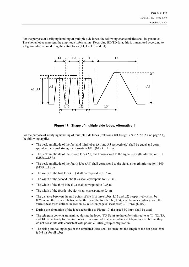
Page 81 of 140
SUBSET-102, Issue 1.0.0
October 4, 2005
For the purpose of verifying handling of multiple side lobes, the following characteristics shall be generated. The shown lobes represent the amplitude information. Regarding BD/TD data, this is transmitted according to telegram information during the entire lobes (L1, L2, L3, and L4).
A1, A3 A2
L34 L12 L23
A4
L2 L4L1 L3
Figure 17: Shape of multiple side lobes, Alternative 1
For the purpose of verifying handling of multiple side lobes (test cases 301 trough 309 in 5.2.8.2.4 on page 83), the following applies:
• The peak amplitude of the first and third lobes (A1 and A3 respectively) shall be equal and corre-spond to the signal strength information 1010 (MSB….LSB).
• The peak amplitude of the second lobe (A2) shall correspond to the signal strength information 1011 (MSB….LSB).
• The peak amplitude of the fourth lobe (A4) shall correspond to the signal strength information 1100 (MSB….LSB).
• The width of the first lobe (L1) shall correspond to 0.15 m.
• The width of the second lobe (L2) shall correspond to 0.20 m.
• The width of the third lobe (L3) shall correspond to 0.25 m.
• The width of the fourth lobe (L4) shall correspond to 0.4 m.
• The distance between the mid points of the first three lobes, L12 and L23 respectively, shall be 0.25 m and the distance between the third and the fourth lobe, L34, shall be in accordance with the various test cases defined in section 5.2.8.2.4 on page 83 (test cases 301 through 309).
• During the simulation of the lobes according to Figure 17, the speed 50 km/h shall be used.
• The telegram contents transmitted during the lobes (TD Data) are hereafter referred to as T1, T2, T3, and T4 respectively for the four lobes. It is assumed that when identical telegrams are chosen, they do not constitute data consistent with possible Balise group configuration.
• The rising and falling edges of the simulated lobes shall be such that the length of the flat peak level is 0.4 ms for all lobes.

Page 82 of 140
SUBSET-102, Issue 1.0.0
October 4, 2005
5.2.8.2.3 General Test Cases
For systems having a coding strategy such that it includes dedicated variables that can be used for determining if different telegrams belong to the same Balise or to two different Balises (e.g., Ebicab 900), the following apply. See also Figure 16 of section 5.2.8.2.2 on page 78 and the corresponding definitions.
L12
T
0.5 m 1.0 m 2.0 m
Different telegrams indicate different Balises. T1 ≠ T2, T2 = T3
TC1 TC2 TC3
Different telegrams indicate different Balises. T1 = T2, T2 ≠ T3
TC4 TC5 TC6
Different telegrams indicate different Balises. T1 ≠ T2, T2 ≠ T3, T1 ≠ T3
TC7 TC8 TC9
T1 = T2 = T3 TC10 TC11 TC12
Different telegrams indicate same Balise. T1 ≠ T2, T2 = T3
TC13 TC14 TC15
Different telegrams indicate same Balise. T1 = T2, T2 ≠ T3
TC16 TC17 TC18
Different telegrams indicate same Balise. T1 ≠ T2, T2 ≠ T3, T1 ≠ T3
TC19 TC20 TC21
Corrupted telegram in the first lobe, T2 = T3 TC22 TC23 TC24
Corrupted telegram in the second lobe, T1 = T3 TC25 TC26 TC27
Corrupted telegram in the third lobe, T1 = T2 TC28 TC29 TC30
Corrupted telegram in all lobes. TC31 TC32 TC33
Table 1: Test Cases when telegram content confirms Balise identity
For systems having a coding strategy and situations such that it is not possible to determine if different telegrams belong to the same Balise or to two different Balises, the following apply. See also Figure 16 of section 5.2.8.2.2 on page 78 and the corresponding definitions.
L12
T
0.5 m 1.0 m 2.0 m
T1 ≠ T2, T2 = T3 TC101 TC102 TC103
T1 = T2, T2 ≠ T3 TC104 TC105 TC106
T1 ≠ T2, T2 ≠ T3, T1 ≠ T3 TC107 TC108 TC109
T1 = T2 = T3 TC110 TC111 TC112
Corrupted telegram in the first lobe, T2 = T3 TC113 TC114 TC115
Corrupted telegram in the second lobe, T1 = T3 TC116 TC117 TC118
Corrupted telegram in the third lobe, T1 = T2 TC119 TC120 TC121
Corrupted telegram in all lobes. TC122 TC123 TC124
Table 2: Test Cases when telegram content does not confirm Balise identity
The test cases according to Table 1 or Table 2 shall be repeated both with and without provision of signal strength data.

Page 83 of 140
SUBSET-102, Issue 1.0.0
October 4, 2005
5.2.8.2.4 Specific Test Cases
For the purpose of testing that the signal strength data is correctly handled when a side lobe is preceding the main lobe, the following test cases shall be applied. See also Figure 16 of section 5.2.8.2.2 on page 78 and the corresponding definitions.
L12
T
0.5 m 1.0 m 2.0 m
Corrupted telegram in the first lobe TC201 TC202 TC203
Corrupted telegram in the second lobe TC204 TC205 TC206
Corrupted telegram in all lobes. TC207 TC208 TC209
Table 3: Test Cases for testing handing of signal strength data
The test cases according to Table 3 shall be repeated both with and without the provision of signal strength data.
For the purpose of testing that multiple side lobes are correctly handled, the following test cases shall be applied. See also Figure 17 of section 5.2.8.2.2 on page 78 and the corresponding definitions.
L34
T
0.5 m 1.0 m 2.0 m
T1 = T2 = T3 =T4 TC301 TC302 TC303
Corrupted telegram in the first three lobes TC304 TC305 TC306
Corrupted telegram in all lobes. TC307 TC308 TC309
Table 4: Test Cases for testing handing of multiple side lobes
It is assumed that identical telegrams are chosen such that they do not constitute data consistent with possible Balise group configuration.
The test cases according to Table 4, shall be repeated both with and without the provision of signal strength data.
For the purpose of testing the behaviour when identical telegrams are consistent with a possible Balise group configuration, the following test cases shall be applied. See also Figure 16 of section 5.2.8.2.2 on page 78 and the corresponding definitions.
L12
T
0.5 m 1.0 m 2.0 m
T1 = T2 TC401 TC402 TC403
Table 5: Test Cases for testing handing consistent Balise group data
It is assumed that the telegrams are chosen such that they constitute data consistent with possible Balise group configuration.
The test cases according to Table 5 shall be repeated both with and without the provision of signal strength data.

Page 84 of 140
SUBSET-102, Issue 1.0.0
October 4, 2005
For the purpose of testing the behaviour when a restrictive aspect message is transmitted in the first lobe, the following test case shall be applied. See also Figure 16 of section 5.2.8.2.2 on page 78 and the corresponding definitions.
L12
T
0.5 m 1.0 m 2.0 m
T1 = Restrictive aspect message, T2 = normal message
TC501 - -
Table 6: Test Cases for testing handing restrictive aspect message
Please observe that this test case must be designed such that the STM recognises that the information is relevant for the selected travelling direction.
The test cases according to Table 6 shall be repeated both with and without the provision of signal strength data.
For the purpose of testing that the signal strength data is correctly handled when a side lobe is succeeding the main lobe, the following test cases shall be applied. See also Figure 16 of section 5.2.8.2.2 on page 78 and the corresponding definitions.
L23
T
0.5 m 1.0 m 2.0 m
Corrupted telegram in the second lobe TC601 TC602 TC603
Corrupted telegram in the third lobe TC604 TC605 TC606
Corrupted telegram in all lobes. TC607 TC608 TC609
Table 7: Test Cases for testing handing of signal strength data
The test cases according to Table 7 shall be repeated both with and without the provision of signal strength data.
For the purpose of testing that the signal strength data is correctly handled over the entire dynamic range when a side lobe is succeeding the main lobe, the following test cases shall be applied. Please observe that each test case involves exploring all possible signal strength levels. See also Figure 16 of section 5.2.8.2.2 on page 78 and the corresponding definitions.
L23
T
0.5 m 1.0 m 2.0 m
Corrupted telegram in the third lobe TC701 TC702 -
Table 8: Test Cases for testing handing of signal strength data
The test cases according to Table 8 shall be repeated both with and without the provision of signal strength data.

Page 85 of 140
SUBSET-102, Issue 1.0.0
October 4, 2005
5.2.8.3 Test Procedure, Management of Side Lobe Effects
The test patterns defined in section 5.2.8.2 on page 77 shall be generated and transmitted to the STM via Inter-face ‘K’.
Test cases according to either Table 1 or Table 2, or both, shall be performed (dependent on the applicable cod-ing strategy and relevant situations). All cases (including those in Table 1 trough Table 7) shall be performed both with and without provision of signal strength data.
The resulting reaction of the STM shall be observed via the STM FFFIS, or via an explicit test interface (if available), and be verified to comply with the acceptance criteria defined in section 5.2.8.4 on page 85.
Link Test Data shall be transmitted on a regular basis outside the Balise contact volume according to UNISIG SUBSET-101.
5.2.8.4 Acceptance Criteria, Management of Side Lobe Effects
The following acceptance criteria apply to the test cases defined in section 5.2.8.2 on page 77.
When it is stated “report” in the table below, the meaning is that the information is either explicitly provided via a suitable test interface, or that the defined evaluation is indicated as part of an overall context (system level oriented reaction).
Case With amplitude data Without amplitude data
TC1 Report T1 as one Balise and T2 from the main lobe as another Balise.
Report T1 as one Balise and T2 from the main lobe as another Balise.
TC2 Report T1 as one Balise and T2 from the main lobe as another Balise.
Report T1 as one Balise and T2 from the main lobe as another Balise.
TC3 Report T1, T2, and T3 as three separate Balises.
Report T1, T2, and T3 as three separate Balises.
TC4 Report T2 from the main lobe as one Bal-ise and T3 as another Balise.
Report T2 from the main lobe as one Bal-ise and T3 as another Balise.
TC5 Report T2 from the main lobe as one Bal-ise and T3 as another Balise.
Report T2 from the main lobe as one Bal-ise and T3 as another Balise.
TC6 Report T1, T2, and T3 as three separate Balises.
Report T1, T2, and T3 as three separate Balises.
TC7 Report T1, T2, and T3 as three separate Balises.
Report T1, T2, and T3 as three separate Balises.
TC8 Report T1, T2, and T3 as three separate Balises.
Report T1, T2, and T3 as three separate Balises.
TC9 Report T1, T2, and T3 as three separate Balises.
Report T1, T2, and T3 as three separate Balises.
TC10 Report T2 from the main lobe as one Bal-ise.
Report T2 from the main lobe as one Bal-ise.
TC11 Report T2 from the main lobe as one Bal-ise.
Report T2 from the main lobe as one Bal-ise.
TC12 Report T1, T2, and T3 as three separate Balises.
Report T1, T2, and T3 as three separate Balises.

Page 86 of 140
SUBSET-102, Issue 1.0.0
October 4, 2005
Case With amplitude data Without amplitude data
TC13 Report T2 from the main lobe as one Bal-ise.
Report T2 from the main lobe as one Bal-ise.
TC14 Report T2 from the main lobe as one Bal-ise.
Report T2 from the main lobe as one Bal-ise.
TC15 Report T2 from the main lobe as one Bal-ise and T3 as another Balise.
Report T2 from the main lobe as one Bal-ise and T3 as another Balise.
TC16 Report T2 from the main lobe as one Bal-ise.
Report T2 from the main lobe as one Bal-ise.
TC17 Report T2 from the main lobe as one Bal-ise.
Report T2 from the main lobe as one Bal-ise.
TC18 Report T1 as one Balise and T2 from the main lobe as another Balise.
Report T1 as one Balise and T2 from the main lobe as another Balise.
TC19 Report T2 from the main lobe as one Bal-ise.
Report T2 from the main lobe as one Bal-ise.
TC20 Report T2 from the main lobe as one Bal-ise.
Report T2 from the main lobe as one Bal-ise.
TC21 Report T2 from the main lobe as one Bal-ise.
Report T2 from the main lobe as one Bal-ise.
TC22 Report T2 from the main lobe as one Bal-ise.
Report T2 from the main lobe as one Bal-ise.
TC23 Report corrupted telegram as one Balise and T2 from the main lobe as another Balise.
Report corrupted telegram as one Balise and T2 from the main lobe as another Balise.
TC24 Report corrupted telegram, T2, and T3 as three separate Balises.
Report corrupted telegram, T2, and T3 as three separate Balises.
TC25 Report corrupted telegram from the main lobe as one Balise.
Report corrupted telegram from the main lobe as one Balise.
TC26 Report T1, corrupted telegram, and T3 as three separate Balises.
Report T1, corrupted telegram, and T3 as three separate Balises.
TC27 Report T1, corrupted telegram, and T3 as three separate Balises.
Report T1, corrupted telegram, and T3 as three separate Balises.
TC28 Report T2 from the main lobe as one Bal-ise.
Report T2 from the main lobe as one Bal-ise.
TC29 Report T2 from the main lobe as one Bal-ise and corrupted telegram as another Balise.
Report T2 from the main lobe as one Bal-ise and corrupted telegram as another Balise.
TC30 Report T1, T2, and corrupted telegram as three separate Balises.
Report T1, T2, and corrupted telegram as three separate Balises.
TC31 Report corrupted telegram from the main lobe as one Balise.
Report corrupted telegram from the main lobe as one Balise.
TC32 Report three corrupted telegrams as three separate Balises.
Report three corrupted telegrams as three separate Balises.
TC33 Report three corrupted telegrams as three separate Balises.
Report three corrupted telegrams as three separate Balises.

Page 87 of 140
SUBSET-102, Issue 1.0.0
October 4, 2005
Case With amplitude data Without amplitude data
TC101 Report T2 from the main lobe as one Bal-ise.
Report T2 from the main lobe as one Bal-ise.
TC102 Report T1 as one Balise and T2 from the main lobe as another Balise. 4
Report T1 as one Balise and T2 from the main lobe as another Balise. 4
TC103 Report T1, T2, and T3 as three separate Balises.
Report T1, T2, and T3 as three separate Balises.
TC104 Report T2 from the main lobe as one Bal-ise.
Report T2 from the main lobe as one Bal-ise.
TC105 Report T2 from the main lobe as one Bal-ise and T3 as another Balise. 4
Report T2 from the main lobe as one Bal-ise and T3 as another Balise. 4
TC106 Report T1, T2, and T3 as three separate Balises.
Report T1, T2, and T3 as three separate Balises.
TC107 Report T2 from the main lobe as one Bal-ise.
Report T2 from the main lobe as one Bal-ise.
TC108 Report T1, T2, and T3 as three separate Balises. 4
Report T1, T2, and T3 as three separate Balises. 4
TC109 Report T1, T2, and T3 as three separate Balises.
Report T1, T2, and T3 as three separate Balises.
TC110 Report T2 from the main lobe as one Bal-ise.
Report T2 from the main lobe as one Bal-ise.
TC111 Report T2 from the main lobe as one Bal-ise.
Report T2 from the main lobe as one Bal-ise.
TC112 Report T1, T2, and T3 as three separate Balises.
Report T1, T2, and T3 as three separate Balises.
TC113 Report T2 from the main lobe as one Bal-ise.
Report T2 from the main lobe as one Bal-ise.
TC114 Report corrupted telegram as one Balise and T2 from the main lobe as another Balise.
Report corrupted telegram as one Balise and T2 from the main lobe as another Balise.
TC115 Report corrupted telegram, T2, and T3 as three separate Balises.
Report corrupted telegram, T2, and T3 as three separate Balises.
TC116 Report corrupted telegram from the main lobe as one Balise.
Report corrupted telegram from the main lobe as one Balise.
TC117 Report T1, corrupted telegram, and T3 as three separate Balises.
Report T1, corrupted telegram, and T3 as three separate Balises.
TC118 Report T1, corrupted telegram, and T3 as three separate Balises.
Report T1, corrupted telegram, and T3 as three separate Balises.
4 Unless the STM through other mechanisms is able to better determine the situation.

Page 88 of 140
SUBSET-102, Issue 1.0.0
October 4, 2005
Case With amplitude data Without amplitude data
TC119 Report T2 from the main lobe as one Bal-ise.
Report T2 from the main lobe as one Bal-ise.
TC120 Report T2 from the main lobe as one Bal-ise and corrupted telegram as another Balise.
Report T2 from the main lobe as one Bal-ise and corrupted telegram as another Balise.
TC121 Report T1, T2, and corrupted telegram as three separate Balises.
Report T1, T2, and corrupted telegram as three separate Balises.
TC122 Report corrupted telegram from the main lobe as one Balise.
Report corrupted telegram from the main lobe as one Balise.
TC123 Report three corrupted telegrams as three separate Balises.
Report three corrupted telegrams as three separate Balises.
TC124 Report three corrupted telegrams as three separate Balises.
Report three corrupted telegrams as three separate Balises.
TC201 Report T2 as one Balise. Report corrupted telegram as one Balise.
TC202 Report corrupted telegram and T2 as two separate Balises.
Report corrupted telegram and T2 as two separate Balises.
TC203 Report corrupted telegram and T2 as two separate Balises.
Report corrupted telegram and T2 as two separate Balises.
TC204 Report corrupted telegram as one Balise. Report T2 as one Balise.
TC205 Report T1 and corrupted telegram as two separate Balises.
Report T1 and corrupted telegram as two separate Balises.
TC206 Report T1 and corrupted telegram as two separate Balises.
Report T1 and corrupted telegram as two separate Balises.
TC207 Report corrupted telegram from the main lobe as one Balise.
Report corrupted telegram from the side lobe as one Balise.
TC208 Report two corrupted telegram as two separate Balises.
Report two corrupted telegram as two separate Balises.
TC209 Report two corrupted telegram as two separate Balises.
Report two corrupted telegram as two separate Balises.
TC301 Report T4 from the main lobe as one Bal-ise.
Report T4 from the main lobe as one Bal-ise.
TC302 Report T4 from the main lobe as one Bal-ise.
Report T4 from the main lobe as one Bal-ise.
TC303 Report T2 from the largest side lobe and T4 from the main lobe as two separate Balise.
Report T3 from the third side lobe and T4 from the main lobe as two separate Balise.
TC304 Report T4 from the main lobe as one Bal-ise.
Report T4 from the main lobe as one Bal-ise.
TC305 Report corrupted telegram from the largest side lobe and T4 from the main lobe as two separate Balise.
Report corrupted telegram from the third side lobe and T4 from the main lobe as two separate Balise.
TC306 Report corrupted telegram from the largest side lobe and T4 from the main lobe as two separate Balise.
Report corrupted telegram from the third side lobe and T4 from the main lobe as two separate Balise.
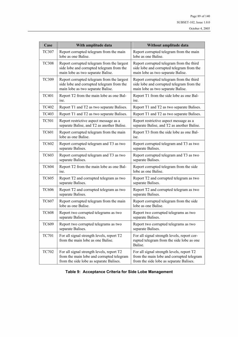
Page 89 of 140
SUBSET-102, Issue 1.0.0
October 4, 2005
Case With amplitude data Without amplitude data
TC307 Report corrupted telegram from the main lobe as one Balise.
Report corrupted telegram from the main lobe as one Balise.
TC308 Report corrupted telegram from the largest side lobe and corrupted telegram from the main lobe as two separate Balise.
Report corrupted telegram from the third side lobe and corrupted telegram from the main lobe as two separate Balise.
TC309 Report corrupted telegram from the largest side lobe and corrupted telegram from the main lobe as two separate Balise.
Report corrupted telegram from the third side lobe and corrupted telegram from the main lobe as two separate Balise.
TC401 Report T2 from the main lobe as one Bal-ise.
Report T1 from the side lobe as one Bal-ise.
TC402 Report T1 and T2 as two separate Balises. Report T1 and T2 as two separate Balises.
TC403 Report T1 and T2 as two separate Balises. Report T1 and T2 as two separate Balises.
TC501 Report restrictive aspect message as a separate Balise, and T2 as another Balise.
Report restrictive aspect message as a separate Balise, and T2 as another Balise.
TC601 Report corrupted telegram from the main lobe as one Balise.
Report T3 from the side lobe as one Bal-ise.
TC602 Report corrupted telegram and T3 as two separate Balises.
Report corrupted telegram and T3 as two separate Balises.
TC603 Report corrupted telegram and T3 as two separate Balises.
Report corrupted telegram and T3 as two separate Balises.
TC604 Report T2 from the main lobe as one Bal-ise.
Report corrupted telegram from the side lobe as one Balise.
TC605 Report T2 and corrupted telegram as two separate Balises.
Report T2 and corrupted telegram as two separate Balises.
TC606 Report T2 and corrupted telegram as two separate Balises.
Report T2 and corrupted telegram as two separate Balises.
TC607 Report corrupted telegram from the main lobe as one Balise.
Report corrupted telegram from the side lobe as one Balise.
TC608 Report two corrupted telegrams as two separate Balises.
Report two corrupted telegrams as two separate Balises.
TC609 Report two corrupted telegrams as two separate Balises.
Report two corrupted telegrams as two separate Balises.
TC701 For all signal strength levels, report T2 from the main lobe as one Balise.
For all signal strength levels, report cor-rupted telegram from the side lobe as one Balise.
TC702 For all signal strength levels, report T2 from the main lobe and corrupted telegram from the side lobe as separate Balises.
For all signal strength levels, report T2 from the main lobe and corrupted telegram from the side lobe as separate Balises.
Table 9: Acceptance Criteria for Side Lobe Management

Page 90 of 140
SUBSET-102, Issue 1.0.0
October 4, 2005
5.2.9 Telegram Decoding
5.2.9.1 General Description, Telegram Decoding
This section defines the test procedure for verifying that the STM has the capability to decode a telegram during worst case conditions in the amount of received bits (i.e., the shortest allowed sequence required for decoding the telegram).
UNISIG SUBSET-100 defines the required amount of error free bits.
5.2.9.2 Test Pattern, Telegram Decoding
The STM manufacturer shall define a suitable test sequence and test patterns such that correct behaviour with respect to the data defined in section 5.2.9.1 is ensured.
Link Test Data shall be transmitted on a regular basis according to UNISIG SUBSET-101 (i.e., link checks shall be performed in accordance with UNISIG SUBSET-101).
Please observe that for some systems, the required number of bits may be dependent on the speed determined by the Time and Odometer information. A relevant number of test points (with respect to velocity) shall in such cases be defined by the supplier of the STM.
5.2.9.3 Test Procedure, Telegram Decoding
1. Transmit a sequence where the BD and TD data is correct for all Balises and chosen such that the minimum required contact length for telegram decoding is simulated.
2. Observe the reaction of the STM via the STM FFFIS.
5.2.9.4 Acceptance Criteria, Telegram Decoding
The following shall be verified via the STM FFFIS:
Step 2 The STM continues to operate without loss of performance.

Page 91 of 140
SUBSET-102, Issue 1.0.0
October 4, 2005
5.3 Laboratory Tests, Alternative 2 Interface
5.3.1 Electrical Data
See section 5.2.1 on page 66.
5.3.2 Data Transmission
See section 5.2.2 on page 67.
5.3.3 Timing Requirements
5.3.3.1 General Description, Timing Requirements
This section defines the test procedure for verifying the ability to cope with extreme timing requirements. The test procedures include verification of the following properties:
• Ability to cope with extreme ASK bit data rates
• Ability to cope with extreme phase difference between various channels (if more than one is imple-mented)
• Ability to cope with extremes in the relation between the Data and CLK signals
5.3.3.2 Test Pattern, Timing Requirements
The STM manufacturer shall define a suitable test sequence and test patterns such that correct handling of the imperfections in the parameters defined in section 5.3.3.1 is ensured.
If not explicitly otherwise defined, Link Tests shall be transmitted on a regular basis according to UNISIG SUBSET-101 (i.e., link tests shall be performed in accordance with UNISIG SUBSET-101).
Page 92 of 140
SUBSET-102, Issue 1.0.0
October 4, 2005
5.3.3.3 Test Procedure, Timing Requirements
1. Transmit the system specific test sequence with the ASK bit data rate in Interface ‘K’ set to the nomi-nal value as defined by UNISIG SUBSET-101.
2. Observe the reaction of the STM via the STM FFFIS.
3. Set the ASK bit data rate in Interface ‘K’ to the lower extreme defined by UNISIG SUBSET-101, and transmit the system specific test sequence.
4. Observe the reaction of the STM via the STM FFFIS.
5. Set the ASK bit data rate in Interface ‘K’ to the upper extreme defined by UNISIG SUBSET-101, and transmit the system specific test sequence.
6. Observe the reaction of the STM via the STM FFFIS.
7. Set the ASK bit data rate in Interface ‘K’ such that it is 50 % outside the lower tolerance in data rate as defined by UNISIG SUBSET-101, and transmit the system specific test sequence.
8. Observe the reaction of the STM via the STM FFFIS (including the reaction time).
9. Set the ASK bit data rate in Interface ‘K’ such that it is 50 % outside the upper tolerance in data rate as defined by UNISIG SUBSET-101, and transmit the system specific test sequence.
10. Observe the reaction of the STM via the STM FFFIS (including the reaction time).
11. Set the CLK pulse length to upper extreme defined by UNISIG SUBSET-101, and transmit the system specific test sequence.
12. Observe the reaction of the STM via the STM FFFIS.
13. Set the CLK pulse length to lower extreme defined by UNISIG SUBSET-101, and transmit the system specific test sequence.
14. Observe the reaction of the STM via the STM FFFIS.
The above steps shall be performed simultaneously transmitting the defined data rates at all channels. Further-more:
15. Simulate the maximum allowed positive phase difference between the involved channels as defined by UNISIG SUBSET-101.
16. Observe the reaction of the STM via the STM FFFIS.
17. Simulate the maximum allowed negative phase difference between the involved channels as defined by UNISIG SUBSET-101.
18. Observe the reaction of the STM via the STM FFFIS.
5.3.3.4 Acceptance Criteria, Timing Requirements
For each of the steps 2, 4, 6, 12, 14, 16, and 18, it shall be verified that the STM continues to operate without loss of performance.
For each of the steps 8 and 10, verify that the manufacturer dependent reaction is obtained within the stipulated reaction time.

Page 93 of 140
SUBSET-102, Issue 1.0.0
October 4, 2005
5.3.4 Functional Data
5.3.4.1 General Description, Functional Data
This section defines the test procedure for verifying the correct reaction on data from a functional perspective. The test procedure includes verification of the following properties:
• Handling of Data • Handling of Eurobalise (FSK) indication • Handling of link tests
The requirements related to diversified data defined in UNISIG SUBSET-101 will also be verified from a re-ceiver perspective. Finally, simulation of the Interface ‘K’ link set to inactive, indicating permanently failing BTM functionality, is also simulated in order to verify that the STM correctly copes with such a situation.
5.3.4.2 Test Pattern, Functional Data
The STM manufacturer shall define a suitable test sequence and test patterns such that the correct behaviour with respect to the data defined in section 5.3.4.1 is ensured.
If not explicitly otherwise defined, Link Tests shall be transmitted on a regular basis according to UNISIG SUBSET-101 (i.e., link tests shall be performed in accordance with UNISIG SUBSET-101).
If otherwise not explicitly mentioned in the test procedure, it is assumed that a correctly operative sequence without imperfections is transmitted. Deviations from this condition (e.g., introduction of failure conditions) are explicitly defined.

Page 94 of 140
SUBSET-102, Issue 1.0.0
October 4, 2005
5.3.4.3 Test Procedure, Functional Data
1. Transmit the correct sequence.
2. Observe the reaction of the STM via the STM FFFIS.
3. For at least one of the Balise passages, introduce incorrect Data.
4. Observe the reaction of the STM via the STM FFFIS.
5. Introduce at least one additional Balise marked as Eurobalise (using the definitions of UNISIG SUBSET-101).
6. Observe the reaction of the STM via the STM FFFIS.
7. Occasionally discontinue the transmission of repetitive link checks such that UNISIG SUBSET-101 is violated in this respect.
8. Observe the reaction of the STM via the STM FFFIS.
9. Occasionally transmit link checks that are longer than the requirements of UNISIG SUBSET-101.
10. Observe the reaction of the STM via the STM FFFIS.
11. Introduce transmission of a long correct Balise passage (e.g., 2 s), and ensure that a correct link test is introduced 1 s after the start of the Balise (thus temporarily interrupting transmission of Balise data).
12. Observe the reaction of the STM via the STM FFFIS.
13. Simulate that Tele-powering is erroneously switched off (indicated through keeping the CLK signal at constant polarity) for a period of more than 500 ms.
14. Observe the reaction of the STM via the STM FFFIS.
15. Set the Interface ‘K’ channel to absence of activity and observe the reaction of the STM via the STM FFFIS.
The above steps shall be performed simultaneously transmitting the same data at all involved channels (except for step 15, where one single link shall be tested at a time). Furthermore:
16. Transmit the correct sequence in one channel, and introduce incorrect Data in the other channel.
17. Observe the reaction of the STM via the STM FFFIS.
18. Transmit the correct sequence in one channel, and introduce in at least one Balise passage that the Balise is marked as Eurobalise in the other channel.
19. Observe the reaction of the STM via the STM FFFIS.
20. Transmit the correct sequence in one channel, and introduce discontinued transmission of repetitive link checks in the other channel.
21. Observe the reaction of the STM via the STM FFFIS.
22. Transmit the correct sequence in one channel, and introduce transmission of too long link tests in the other channel.
23. Observe the reaction of the STM via the STM FFFIS.
24. Transmit the correct sequence in one channel, and introduce for a period of time exceeding 500 ms that Tele-powering is erroneously switched off in the other channel (indicated through keeping the CLK signal at constant polarity).
25. Observe the reaction of the STM via the STM FFFIS.
The steps from step 16 until the end shall be repeated such that the abnormalities in the sequences are applied to one channel at a time (while the others have normal conditions).

Page 95 of 140
SUBSET-102, Issue 1.0.0
October 4, 2005
5.3.4.4 Acceptance Criteria, Functional Data
The following shall be verified via the STM FFFIS:
Step 2 The STM continues to operate without loss of performance.
Step 4 The STM detects all Balises, and detects the situation with loss of telegram. Verify that the manufacturer dependent reaction is obtained within the stipulated reaction time.
Step 6 The STM continues to operate without loss of performance.
Step 8 The STM detects that link checks are missing. Verify that the manufacturer dependent reac-tion is obtained within the stipulated reaction time.
Step 10 The STM detects that link checks are too long. Verify that the manufacturer dependent reac-tion is obtained within the stipulated reaction time.
Step 12 The STM continues to operate without loss of performance.
Step 14 The STM detects that ERMS is unavailable. Verify that the manufacturer dependent reaction is obtained within the stipulated reaction time.
Step 15 The STM detects that Interface ‘K’ is not active. Verify that the manufacturer dependent reac-tion is obtained within the stipulated reaction time.
Step 17 The STM detects all Balises, and detects the situation with loss of telegram. Verify that the manufacturer dependent reaction is obtained within the stipulated reaction time.
Step 19 The STM continues to operate without loss of performance.
Step 21 The STM detects that link checks are missing. Verify that the manufacturer dependent reac-tion is obtained within the stipulated reaction time.
Step 23 The STM detects that link checks are too long. Verify that the manufacturer dependent reac-tion is obtained within the stipulated reaction time.
Step 25 The STM detects that ERTMS is not available. Verify that the manufacturer dependent reac-tion is obtained within the stipulated reaction time.

Page 96 of 140
SUBSET-102, Issue 1.0.0
October 4, 2005
5.3.5 Link Check Functionality
5.3.5.1 General Description, Link Check Functionality
This section defines the test procedure for verifying the correct reaction on signalling used for on-line supervi-sion of the Interface ‘K’ link. The test procedure includes verification of the following properties:
• Correct reaction on link check pattern
5.3.5.2 Test Pattern, Link Check Functionality
The STM manufacturer shall define a suitable test sequence and test patterns such that correct behaviour with respect to the data defined in section 5.3.5.1 is ensured.
No Balise passages shall be simulated (unless the possible initial sequence required for setting the system in a define state/mode), and the time between successive link checks shall be set to 400 ms.
5.3.5.3 Test Procedure, Link Check Functionality
1. Transmit the correct link check pattern.
2. Observe the reaction of the STM via the STM FFFIS.
3. Transmit a link check pattern but with too long duration.
4. Observe the reaction of the STM via the STM FFFIS.
5. Transmit a link check pattern according to SUBSET-101, but with Data held at logical low level af-ter the CLC signal is held at permanently low logical level.
6. Observe the reaction of the STM via the STM FFFIS.
7. Transmit a link check pattern according to SUBSET-101, but with Data held at permanently high logical level throughout the sequence.
8. Observe the reaction of the STM via the STM FFFIS.
5.3.5.4 Acceptance Criteria, Link Check Functionality
The following shall be verified via the STM FFFIS:
Step 2 The STM continues to operate without loss of performance.
Steps 4, 6, and 8 The STM detects that link checks are corrupt. Verify that the manufacturer depend-ent reaction is obtained within the stipulated reaction time.
In case of several channels, the STM shall detect if a failure condition is occurring in any single channel.

Page 97 of 140
SUBSET-102, Issue 1.0.0
October 4, 2005
5.3.6 Handling of Diversified Data
Fulfilment of the basic requirements for ensuring correct handling of diversified data is verified through the tests included in section 5.3.4 on page 93.
5.3.7 Detection of Balises
5.3.7.1 General Description, Detection of Balises
See section 5.2.7.1 on page 76.
5.3.7.2 Test Pattern, Detection of Balises
See section 5.2.7.2 on page 76.
5.3.7.3 Test Procedure, Detection of Balises
1. Transmit a sequence where the Data is correct for all Balises and chosen such that the minimum re-quired contact length for Balise Detect is simulated.
2. Observe the reaction of the STM via the STM FFFIS.
5.3.7.4 Acceptance Criteria, Detection of Balises
The following shall be verified via the STM FFFIS:
Step 2 The STM either continues to operate without loss of performance.

Page 98 of 140
SUBSET-102, Issue 1.0.0
October 4, 2005
5.3.8 Management of Side Lobe Effects
5.3.8.1 General Description, Management of Side Lobe Effects
This section defines the test procedure for verifying the correct reaction in the presence of various side lobe conditions. The test procedure includes verification of the following properties:
• Handling of side lobes positioned at various distances from the main lobe • Handling of telegram shift in combination with side lobes • Handling of side lobes when no telegram decoding is possible • Handling of multiple side lobes • Behaviour when restrictive aspect messages are transmitted
In general, all test cases should be designed such that the specific properties detailed herein are put in a wider context in order to constitute meaningful system specific information that can be handled by the STM (and a relevant reaction can be observed). It is the responsibility of the STM manufacturer to define the needed details. It should be observed that the specifics in the patterns aiming at verifying the side lobe handling properties shall be such that it is possible to positively identify the reaction (e.g., unique telegrams shall be used in various lobes unless explicitly stated to be identical, and these shall be selected such that different system reactions are ob-tained if the reaction is observed on system level).
Telegram contents indicated herein (T1, T2, etc.) are system specific, and need to be defined by the STM manu-facturer. The indications on indicated telegram contents are not global (i.e., T1 in one test case may be different from T1 in another test case).
If it is found suitable, a specific test interface may be implemented on the STM. Via such a test interface, de-tailed reporting on selection of lobes and telegram contents may be provided (rather than observing system oriented reactions via the STM FFFIS). If a specific test interface is adopted, the manufacturer shall through specific verifications prove that the test interface response is correlated with the operational STM algorithms
5.3.8.2 Test Pattern, Management of Side Lobe Effects
5.3.8.2.1 General
The STM manufacturer shall define suitable test sequences and test patterns such that the correct behaviour with respect to the mechanisms defined in section 5.3.8.1 is ensured.
Link tests shall be transmitted on a regular basis according to UNISIG SUBSET-101 (i.e., link tests shall be performed in accordance with UNISIG SUBSET-101).
It is in general assumed that a correctly operative sequence without imperfections is transmitted unless otherwise explicitly defined.
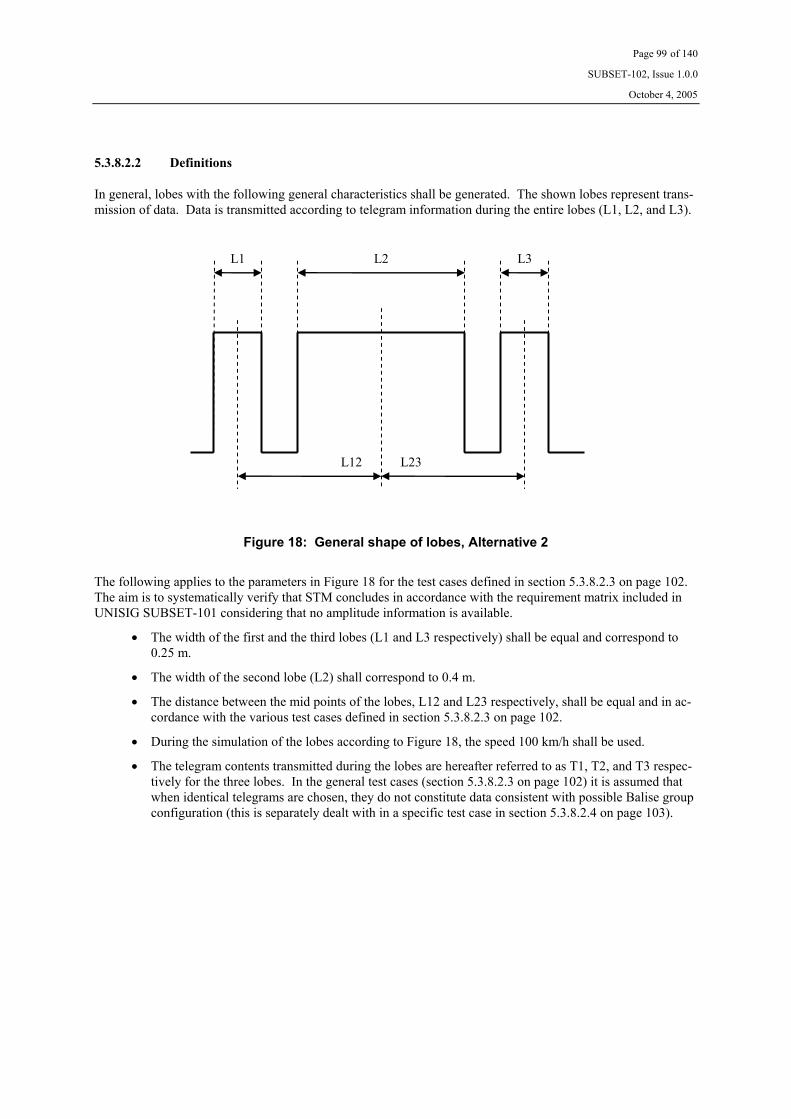
Page 99 of 140
SUBSET-102, Issue 1.0.0
October 4, 2005
5.3.8.2.2 Definitions
In general, lobes with the following general characteristics shall be generated. The shown lobes represent trans-mission of data. Data is transmitted according to telegram information during the entire lobes (L1, L2, and L3).
L23 L12
L3L2L1
Figure 18: General shape of lobes, Alternative 2
The following applies to the parameters in Figure 18 for the test cases defined in section 5.3.8.2.3 on page 102. The aim is to systematically verify that STM concludes in accordance with the requirement matrix included in UNISIG SUBSET-101 considering that no amplitude information is available.
• The width of the first and the third lobes (L1 and L3 respectively) shall be equal and correspond to 0.25 m.
• The width of the second lobe (L2) shall correspond to 0.4 m.
• The distance between the mid points of the lobes, L12 and L23 respectively, shall be equal and in ac-cordance with the various test cases defined in section 5.3.8.2.3 on page 102.
• During the simulation of the lobes according to Figure 18, the speed 100 km/h shall be used.
• The telegram contents transmitted during the lobes are hereafter referred to as T1, T2, and T3 respec-tively for the three lobes. In the general test cases (section 5.3.8.2.3 on page 102) it is assumed that when identical telegrams are chosen, they do not constitute data consistent with possible Balise group configuration (this is separately dealt with in a specific test case in section 5.3.8.2.4 on page 103).

Page 100 of 140
SUBSET-102, Issue 1.0.0
October 4, 2005
For the purpose of verifying handling of only one side lobe before the main lobe (test cases 201 trough 209 in section 5.3.8.2.4 on page 103), the following applies. The aim is to verify that the STM correctly makes the correct decision on main lobe.
• The third lobe shall not be generated (L3 = 0)
• The width of the first lobe (L1) shall correspond to 0.25 m.
• The width of the second lobe (L2) shall correspond to 0.4 m.
• The distance between the mid points of the lobes, L12, shall be in accordance with the various test cases defined in section 5.3.8.2.4 on page 103 (test cases 201 through 209).
• During the simulation of the lobes according to Figure 18, the speed 100 km/h shall be used.
• The telegram contents transmitted during the lobes are hereafter referred to as T1 and T2 respectively for the two lobes.
The above also applies to testing the behaviour when the first lobe includes transmission of a restrictive aspect message (test case 501 in section 5.3.8.2.3 on page 102).
For the purpose of verifying handling of only one side lobe after the main lobe (test cases 601 trough 609 in section 5.3.8.2.4 on page 103), the following applies. The aim is to verify that the STM correctly makes the correct decision on main lobe.
• The first lobe shall not be generated (L1 = 0)
• The width of the third lobe (L3) shall correspond to 0.25 m.
• The width of the second lobe (L2) shall correspond to 0.4 m.
• The distance between the mid points of the lobes, L23, shall be in accordance with the various test cases defined in section 5.3.8.2.4 on page 103 (test cases 601 through 609).
• During the simulation of the lobes according to Figure 18, the speed 100 km/h shall be used.
• The telegram contents transmitted during the lobes are hereafter referred to as T2 and T3 respectively for the two lobes.
For the specific case that identical telegrams are chosen such that they constitute data consistent with possible Balise group configuration (test cases 401 through 403 in section 5.3.8.2.4 on page 103), the following applies:
• The third lobe shall not be generated (L3 = 0)
• The width of the first lobe (L1) shall correspond to 0.25 m.
• The width of the second lobe (L2) shall correspond to 0.4 m.
• The distance between the mid points of the lobes, L12, shall be in accordance with the various test cases defined in section 5.3.8.2.4 on page 103 (test cases 401 through 403).
• During the simulation of the lobes according to Figure 18, the speed 100 km/h shall be used.
• The telegram contents transmitted during the lobes are hereafter referred to as T1 and T2 respectively for the two lobes. It is assumed that identical telegrams are chosen such that they constitute data con-sistent with possible Balise group.

Page 101 of 140
SUBSET-102, Issue 1.0.0
October 4, 2005
For the purpose of verifying handling of multiple side lobes, the following characteristics shall be generated. The shown lobes represent data transmission. Data is transmitted according to telegram information during the entire lobes (L1, L2, L3, and L4).
L34 L12 L23
L2 L4L1 L3
Figure 19: Shape of multiple side lobes, Alternative 2
For the purpose of verifying handling of multiple side lobes (test cases 301 trough 309 in 5.3.8.2.4 on page 103), the following applies:
• The width of the first lobe (L1) shall correspond to 0.15 m.
• The width of the second lobe (L2) shall correspond to 0.20 m.
• The width of the third lobe (L3) shall correspond to 0.25 m.
• The width of the fourth lobe (L4) shall correspond to 0.4 m.
• The distance between the mid points of the first three lobes, L12 and L23 respectively, shall be 0.25 m and the distance between the third and the fourth lobe, L34, shall be in accordance with the various test cases defined in section 5.3.8.2.4 on page 103 (test cases 301 through 309).
• During the simulation of the lobes according to Figure 19, the speed 50 km/h shall be used.
• The telegram contents transmitted during the lobes are hereafter referred to as T1, T2, T3, and T4 re-spectively for the four lobes. It is assumed that when identical telegrams are chosen, they do not con-stitute data consistent with possible Balise group configuration.

Page 102 of 140
SUBSET-102, Issue 1.0.0
October 4, 2005
5.3.8.2.3 General Test Cases
For systems having a coding strategy such that it includes dedicated variables that can be used for determining if different telegrams belong to the same Balise or to two different Balises (e.g., Ebicab 900), the following apply. See also Figure 18 of section 5.3.8.2.2 on page 99 and the corresponding definitions.
L12
T
0.5 m 1.0 m 2.0 m
Different telegrams indicate different Balises. T1 ≠ T2, T2 = T3
TC1 TC2 TC3
Different telegrams indicate different Balises. T1 = T2, T2 ≠ T3
TC4 TC5 TC6
Different telegrams indicate different Balises. T1 ≠ T2, T2 ≠ T3, T1 ≠ T3
TC7 TC8 TC9
T1 = T2 = T3 TC10 TC11 TC12
Different telegrams indicate same Balise. T1 ≠ T2, T2 = T3
TC13 TC14 TC15
Different telegrams indicate same Balise. T1 = T2, T2 ≠ T3
TC16 TC17 TC18
Different telegrams indicate same Balise. T1 ≠ T2, T2 ≠ T3, T1 ≠ T3
TC19 TC20 TC21
Corrupted telegram in the first lobe, T2 = T3 TC22 TC23 TC24
Corrupted telegram in the second lobe, T1 = T3 TC25 TC26 TC27
Corrupted telegram in the third lobe, T1 = T2 TC28 TC29 TC30
Corrupted telegram in all lobes. TC31 TC32 TC33
Table 10: Test Cases when telegram content confirms Balise identity
For systems having a coding strategy and situations such that it is not possible to determine if different telegrams belong to the same Balise or to two different Balises, the following apply. See also Figure 18 of section 5.3.8.2.2 on page 99 and the corresponding definitions.
L12
T
0.5 m 1.0 m 2.0 m
T1 ≠ T2, T2 = T3 TC101 TC102 TC103
T1 = T2, T2 ≠ T3 TC104 TC105 TC106
T1 ≠ T2, T2 ≠ T3, T1 ≠ T3 TC107 TC108 TC109
T1 = T2 = T3 TC110 TC111 TC112
Corrupted telegram in the first lobe, T2 = T3 TC113 TC114 TC115
Corrupted telegram in the second lobe, T1 = T3 TC116 TC117 TC118
Corrupted telegram in the third lobe, T1 = T2 TC119 TC120 TC121
Corrupted telegram in all lobes. TC122 TC123 TC124
Table 11: Test Cases when telegram content does not confirm Balise identity

Page 103 of 140
SUBSET-102, Issue 1.0.0
October 4, 2005
5.3.8.2.4 Specific Test Cases
For the purpose of testing handling when only one side lobe is preceding the main lobe, the following test cases shall be applied. See also Figure 18 of section 5.3.8.2.2 on page 99 and the corresponding definitions.
L12
T
0.5 m 1.0 m 2.0 m
Corrupted telegram in the first lobe TC201 TC202 TC203
Corrupted telegram in the second lobe TC204 TC205 TC206
Corrupted telegram in all lobes. TC207 TC208 TC209
Table 12: Test Cases for testing handing preceding side lobes
For the purpose of testing that multiple side lobes are correctly handled, the following test cases shall be applied. See also Figure 19 of section 5.3.8.2.2 on page 99 and the corresponding definitions.
L34
T
0.5 m 1.0 m 2.0 m
T1 = T2 = T3 =T4 TC301 TC302 TC303
Corrupted telegram in the first three lobes TC304 TC305 TC306
Corrupted telegram in all lobes. TC307 TC308 TC309
Table 13: Test Cases for testing handing of multiple side lobes
It is assumed that identical telegrams are chosen such that they do not constitute data consistent with possible Balise group configuration.
For the purpose of testing the behaviour when identical telegrams are consistent with a possible Balise group configuration, the following test cases shall be applied. See also Figure 18 of section 5.3.8.2.2 on page 99 and the corresponding definitions.
L12
T
0.5 m 1.0 m 2.0 m
T1 = T2 TC401 TC402 TC403
Table 14: Test Cases for testing handing consistent Balise group data
It is assumed that the telegrams are chosen such that they constitute data consistent with possible Balise group configuration.
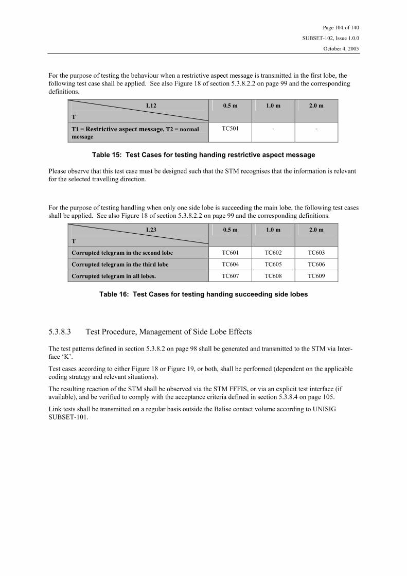
Page 104 of 140
SUBSET-102, Issue 1.0.0
October 4, 2005
For the purpose of testing the behaviour when a restrictive aspect message is transmitted in the first lobe, the following test case shall be applied. See also Figure 18 of section 5.3.8.2.2 on page 99 and the corresponding definitions.
L12
T
0.5 m 1.0 m 2.0 m
T1 = Restrictive aspect message, T2 = normal message
TC501 - -
Table 15: Test Cases for testing handing restrictive aspect message
Please observe that this test case must be designed such that the STM recognises that the information is relevant for the selected travelling direction.
For the purpose of testing handling when only one side lobe is succeeding the main lobe, the following test cases shall be applied. See also Figure 18 of section 5.3.8.2.2 on page 99 and the corresponding definitions.
L23
T
0.5 m 1.0 m 2.0 m
Corrupted telegram in the second lobe TC601 TC602 TC603
Corrupted telegram in the third lobe TC604 TC605 TC606
Corrupted telegram in all lobes. TC607 TC608 TC609
Table 16: Test Cases for testing handing succeeding side lobes
5.3.8.3 Test Procedure, Management of Side Lobe Effects
The test patterns defined in section 5.3.8.2 on page 98 shall be generated and transmitted to the STM via Inter-face ‘K’.
Test cases according to either Figure 18 or Figure 19, or both, shall be performed (dependent on the applicable coding strategy and relevant situations).
The resulting reaction of the STM shall be observed via the STM FFFIS, or via an explicit test interface (if available), and be verified to comply with the acceptance criteria defined in section 5.3.8.4 on page 105.
Link tests shall be transmitted on a regular basis outside the Balise contact volume according to UNISIG SUBSET-101.
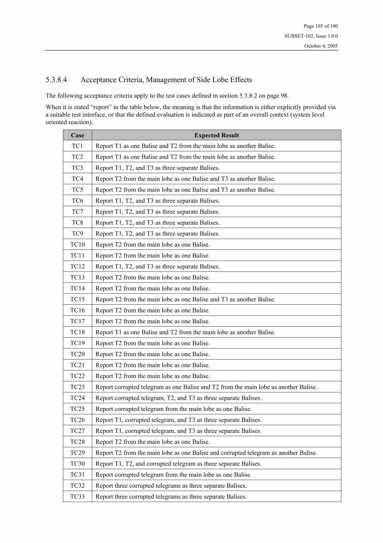
Page 105 of 140
SUBSET-102, Issue 1.0.0
October 4, 2005
5.3.8.4 Acceptance Criteria, Management of Side Lobe Effects
The following acceptance criteria apply to the test cases defined in section 5.3.8.2 on page 98.
When it is stated “report” in the table below, the meaning is that the information is either explicitly provided via a suitable test interface, or that the defined evaluation is indicated as part of an overall context (system level oriented reaction).
Case Expected Result
TC1 Report T1 as one Balise and T2 from the main lobe as another Balise.
TC2 Report T1 as one Balise and T2 from the main lobe as another Balise.
TC3 Report T1, T2, and T3 as three separate Balises.
TC4 Report T2 from the main lobe as one Balise and T3 as another Balise.
TC5 Report T2 from the main lobe as one Balise and T3 as another Balise.
TC6 Report T1, T2, and T3 as three separate Balises.
TC7 Report T1, T2, and T3 as three separate Balises.
TC8 Report T1, T2, and T3 as three separate Balises.
TC9 Report T1, T2, and T3 as three separate Balises.
TC10 Report T2 from the main lobe as one Balise.
TC11 Report T2 from the main lobe as one Balise.
TC12 Report T1, T2, and T3 as three separate Balises.
TC13 Report T2 from the main lobe as one Balise.
TC14 Report T2 from the main lobe as one Balise.
TC15 Report T2 from the main lobe as one Balise and T3 as another Balise.
TC16 Report T2 from the main lobe as one Balise.
TC17 Report T2 from the main lobe as one Balise.
TC18 Report T1 as one Balise and T2 from the main lobe as another Balise.
TC19 Report T2 from the main lobe as one Balise.
TC20 Report T2 from the main lobe as one Balise.
TC21 Report T2 from the main lobe as one Balise.
TC22 Report T2 from the main lobe as one Balise.
TC23 Report corrupted telegram as one Balise and T2 from the main lobe as another Balise.
TC24 Report corrupted telegram, T2, and T3 as three separate Balises.
TC25 Report corrupted telegram from the main lobe as one Balise.
TC26 Report T1, corrupted telegram, and T3 as three separate Balises.
TC27 Report T1, corrupted telegram, and T3 as three separate Balises.
TC28 Report T2 from the main lobe as one Balise.
TC29 Report T2 from the main lobe as one Balise and corrupted telegram as another Balise.
TC30 Report T1, T2, and corrupted telegram as three separate Balises.
TC31 Report corrupted telegram from the main lobe as one Balise.
TC32 Report three corrupted telegrams as three separate Balises.
TC33 Report three corrupted telegrams as three separate Balises.

Page 106 of 140
SUBSET-102, Issue 1.0.0
October 4, 2005
Case Expected Result
TC101 Report T2 from the main lobe as one Balise.
TC102 Report T1 as one Balise and T2 from the main lobe as another Balise. 5
TC103 Report T1, T2, and T3 as three separate Balises.
TC104 Report T2 from the main lobe as one Balise.
TC105 Report T2 from the main lobe as one Balise and T3 as another Balise. 5
TC106 Report T1, T2, and T3 as three separate Balises.
TC107 Report T2 from the main lobe as one Balise.
TC108 Report T1, T2, and T3 as three separate Balises. 5
TC109 Report T1, T2, and T3 as three separate Balises.
TC110 Report T2 from the main lobe as one Balise.
TC111 Report T2 from the main lobe as one Balise.
TC112 Report T1, T2, and T3 as three separate Balises.
TC113 Report T2 from the main lobe as one Balise.
TC114 Report corrupted telegram as one Balise and T2 from the main lobe as another Balise.
TC115 Report corrupted telegram, T2, and T3 as three separate Balises.
TC116 Report corrupted telegram from the main lobe as one Balise.
TC117 Report T1, corrupted telegram, and T3 as three separate Balises.
TC118 Report T1, corrupted telegram, and T3 as three separate Balises.
TC119 Report T2 from the main lobe as one Balise.
TC120 Report T2 from the main lobe as one Balise and corrupted telegram as another Balise.
TC121 Report T1, T2, and corrupted telegram as three separate Balises.
TC122 Report corrupted telegram from the main lobe as one Balise.
TC123 Report three corrupted telegrams as three separate Balises.
TC124 Report three corrupted telegrams as three separate Balises.
TC201 Report T2 as one Balise.
TC202 Report corrupted telegram and T2 as two separate Balises.
TC203 Report corrupted telegram and T2 as two separate Balises.
TC204 Report corrupted telegram as one Balise.
TC205 Report T1 and corrupted telegram as two separate Balises.
TC206 Report T1 and corrupted telegram as two separate Balises.
TC207 Report corrupted telegram from the main lobe as one Balise.
TC208 Report two corrupted telegram as two separate Balises.
TC209 Report two corrupted telegram as two separate Balises.
5 Unless the STM through other mechanisms is able to better determine the situation.

Page 107 of 140
SUBSET-102, Issue 1.0.0
October 4, 2005
Case Expected Result
TC301 Report T4 from the main lobe as one Balise.
TC302 Report T4 from the main lobe as one Balise.
TC303 Report T3 from the third side lobe and T4 from the main lobe as two separate Balise.
TC304 Report T4 from the main lobe as one Balise.
TC305 Report corrupted telegram from the third side lobe and T4 from the main lobe as two separate Balise.
TC306 Report corrupted telegram from the third side lobe and T4 from the main lobe as two separate Balise.
TC307 Report corrupted telegram from the main lobe as one Balise.
TC308 Report corrupted telegram from the third side lobe and corrupted telegram from the main lobe as two separate Balise.
TC309 Report corrupted telegram from the third side lobe and corrupted telegram from the main lobe as two separate Balise.
TC401 Report T2 as one Balise.
TC402 Report T1 and T2 as two separate Balises.
TC403 Report T1 and T2 as two separate Balises.
TC501 Report restrictive aspect message as a separate Balise, and T2 as another Balise.
TC601 Report corrupted telegram as one Balise.
TC602 Report corrupted telegram and T3 as two separate Balises.
TC603 Report corrupted telegram and T3 as two separate Balises.
TC604 Report T2 as one Balise.
TC605 Report T2 and corrupted telegram as two separate Balises.
TC606 Report T2 and corrupted telegram as two separate Balises.
TC607 Report corrupted telegram from the main lobe as one Balise.
TC608 Report two corrupted telegrams as two separate Balises.
TC609 Report two corrupted telegrams as two separate Balises.
Table 17: Acceptance Criteria for Side Lobe Management

Page 108 of 140
SUBSET-102, Issue 1.0.0
October 4, 2005
5.3.9 Telegram Decoding
5.3.9.1 General Description, Telegram Decoding
See section 5.2.9.1 on page 90.
5.3.9.2 Test Pattern, Telegram Decoding
See section 5.2.9.2 on page 90.
5.3.9.3 Test Procedure, Telegram Decoding
1. Transmit a sequence where the Data is correct for all Balises and chosen such that the minimum re-quired contact length for telegram decoding is simulated.
2. Observe the reaction of the STM via the STM FFFIS.
5.3.9.4 Acceptance Criteria, Telegram Decoding
The following shall be verified via the STM FFFIS:
Step 2 The STM continues to operate without loss of performance.
5.4 Requirements for Test Tools
See UNISIG SUBSET-085, and applicable annexes herein.

Page 109 of 140
SUBSET-102, Issue 1.0.0
October 4, 2005
Annex A, Measurement Points
A1 Test Points for Contact Zone and Side-lobe Zone In general, the geometrical test points shall be chosen such that various Antenna Units can be verified with respect to the required contact length and considering potential side lobes at different lateral deviations.
The Antenna Units shall be verified for minimum, nominal, and maximum heights. The nominal height is de-fined as the sum of the mean value of the static position for the Antenna Unit in question, and the highest speci-fied position of the Balise. This section defines the full set of geometrical test points. Tailoring will be made during certain tests (see test matrices according to chapters A3 and A4 on pages 111 and 112 respectively).
During testing, the X-positions should be selected according to:
From 0 mm to ± 500 mm, in steps of 20 mm (total of 51 points).
From ± 550 mm to ± 1300 mm, in steps of 50 mm (total of 32 points).
The first zone (from 0 to ± 500 mm) is referred to as contact zone in the test matrices of chapters A3 and A4 on pages 111 and 112 respectively, and the second zone (from ± 500 mm to ± 1300 mm) is referred to as side lobe zone.
The lateral positions (Y-positions) shall be defined by the Antenna Unit supplier (for each lateral deviation, testing shall be performed at the X-positions defined above).
The geometrical test position [X = 0, Y = 0, Z = maximum height] is denominated the geometrical reference point (see sections 4.2.6.2.1 and 4.2.6.3.1 on page 36 and 40 respectively).
It is the responsibility of the supplier of the Antenna Unit to define the profile of maximum lateral deviation versus vehicle speed. This profile shall take into consideration the requirements on Balise installation (specified in UNISIG SUBSET-100), and the installation dependent requirements for each Antenna Unit type in question (defined by the supplier of the Antenna).

Page 110 of 140
SUBSET-102, Issue 1.0.0
October 4, 2005
A2 Test Points for Cross-talk Protected Zone The following geometrical positions shall be tested:
Point x [mm]
y [mm]
Point x [mm]
y [mm]
CT1 0 +1400 CT2 0 -1400
CT3 0 +1600 CT4 0 -1600
CT5 0 +1800 CT6 0 -1800
CT7 0 +2000 CT8 0 -2000
CT9 0 +2200 CT10 0 -2200
CT11 0 +2400 CT12 0 -2400
CT13 0 +2600 CT14 0 -2600
CT15 0 +2800 CT16 0 -2800
CT17 0 +3000 CT18 0 -3000
CT19 0 +3200 CT20 0 -3200
CT21 0 +3400 CT22 0 -3400
CT23 0 +3600 CT24 0 -3600
CT25 +1400 0 CT26 -1400 0
CT27 +1600 0 CT28 -1600 0
CT29 +1800 0 CT30 -1800 0
CT31 +2000 0 CT32 -2000 0
CT33 +2200 0 CT34 -2200 0
CT35 +2400 0 CT36 -2400 0
CT37 +2600 0 CT38 -2600 0
CT39 +2800 0 CT40 -2800 0
CT41 +3000 0 CT42 -3000 0
CT43 +3200 0 CT44 -3200 0
CT45 +3400 0 CT46 -3400 0
CT47 +3600 0 CT48 -3600 0
Table 18: Geometrical test points for On-board Cross-talk verification
The Antenna Unit shall be positioned at the minimum and the maximum heights as defined by the supplier.

Page 111 of 140
SUBSET-102, Issue 1.0.0
October 4, 2005
A3 Test Matrix for Transmission and Cross-talk tests A3.1 Test Conditions versus Test Zones
The following applies to tests defined by the sections 4.2.6.2 on page 36, 4.2.6.4 on page 46, and 4.2.6.8 on page 52. The test zones referred to in the table are defined in the chapters A1 on page 109 and A2 on page 110.
The following combinations of test conditions and test zones shall be tested:
Test Condition Section Contact Zone
Side Lobe Zone Cross-talk Zone
Nominal 4.1.4.1 X X X
Tilt 4.1.4.2.1 X X
Pitch 4.1.4.2.1 X X
Salt Water 4.1.4.2.2 X
Clear Water 4.1.4.2.2 X
Iron Ore 4.1.4.2.2 X
Table 19: Transmission and Cross-talk Tests, Test Conditions versus Test Zones
Performance over temperature range is considered through spot check evaluation according to section 4.2.6.2.2 on page 38 (and section 4.2.6.3 on page 40).
A3.2 Test Conditions versus Geometrical Test Points
The following applies to tests defined by the sections 4.2.6.2 on page 36, 4.2.6.4 on page 46, and 4.2.6.8 on page 52. The test zones referred to in the table are defined in the chapters A1 on page 109 and A2 on page 110.
During the testing, the number of test points within the contact and side lobe zone shall be according to Table 20 below. The reason is that the number of test points defined in section A1 on page 109 needs to be minimised.
Test Condition Section Full R1 R2
Nominal 4.1.4.1 X
Tilt 4.1.4.2.1 X
Pitch 4.1.4.2.1 X
Salt Water 4.1.4.2.2 X
Clear Water 4.1.4.2.2 X
Iron Ore 4.1.4.2.2 X
Table 20: Transmission and Cross-talk Tests, Geometrical Test Points within the Contact Zone
The following is applicable:
• ‘Full’ indicates all points according to section A1 on page 109. • ‘R1’ indicates maximum and minimum height only. In addition to this, a further limitation is that minimum
height only applies within the side lobe zone. • ‘R2’ indicates maximum height only.

Page 112 of 140
SUBSET-102, Issue 1.0.0
October 4, 2005
A4 Test Matrix for Other Characteristics A4.1 Test Conditions versus Characteristics
The following applies to tests defined by the sections 4.2.6.7 on page 51, 4.2.6.5 on page 49, and 4.2.6.6 on page 49. The applicable geometrical test points are further defined by chapter A1 on page 109.
The following combinations of characteristics and test conditions shall be tested:
Test Condition Section Up-link Electrical Char.(Section 4.2.6.7)
Tele-powering Char. (Section 4.2.6.5)
Maximum Flux Level(Section 4.2.6.6)
Nominal6 4.1.4.1 X X X
Tilt 4.1.4.2.1
Pitch 4.1.4.2.1
Salt Water 4.1.4.2.2
Clear Water 4.1.4.2.2
Iron Ore 4.1.4.2.2
Table 21: Other Characteristics, Characteristics versus Test Conditions
Tele-powering Characteristics are evaluated at nominal temperature, and at upper and lower temperature ex-tremes.
A4.2 Test Conditions versus Geometrical Test Points
The following applies to tests defined by the sections 4.2.6.7 on page 51, 4.2.6.5 on page 49, and 4.2.6.6 on page 49. The applicable geometrical test points are further defined by chapter A1 on page 109.
During the testing, the number of test points within the Contact and Side Lobe Zone shall be according to Table 22 below. Testing within the cross-talk zone is not applicable for these tests. The reason is that the number of test points defined in chapter A1 on page 109 need to be minimised.
Test Case Section R3 R4 R5 Up-link Electrical Characteristics
4.2.6.7 X X
Tele-powering Characteristics
4.2.6.5 X
Maximum Flux Level 4.2.6.6 X
Table 22: Other Characteristics, Geometrical Test Points
The following is applicable:
• ‘R3’ indicates nominal height with no lateral displacement only. • ‘R4’ indicates nominal height at position [X=0, Y=0] only. • ‘R5’ indicates minimum height with no lateral displacement and within the Contact Zone only.
6 Applicable parts of nominal conditions apply (e.g., during tests of Up-link Electrical Characteristics the
conditions for the Up-link signal are modified in accordance with the test procedure). Please refer to the specific test procedures for more details.

Page 113 of 140
SUBSET-102, Issue 1.0.0
October 4, 2005
Annex B, Test Tools and Instruments
B1 Recommended Test Tools and Instruments The following list includes suitable test equipment. Other equipment with similar performance may substitute these. “Item” refers to numbers in the Test and Calibration configurations.
Item: Equipment: Type: Comment:
2 Attenuator 6 dB
3 RF Power Amplifier ENI A150 100 W
4 Attenuator 3 dB 100 W
7 Reference Loop various, see SUBSET-085
10 Power Meter Power Sensors
R&S NRVD R&S NRV-Z5
12 Low Pass Filter Mini Circuits, BLP-10.7
13 Signal Generator AWG 520
14 Current Sense Balun See SUBSET-085 Has to be calibrated
20 General purpose Balun See SUBSET-085
29 Attenuator 3 dB 30 W
31 Attenuator 20 dB 20 W, VSWR < 1:1.05
32 Current probe Tektronix CT-2 Has to be calibrated
34 Interface ‘V1’ adapter Supplier specific
35 Spectrum Analyser HP 8594E
36 RF Switch CX-600N Toyo Tsusho
37 Oscilloscope TDS 754A Tektronix
38 Laboratory Test Management System
See SUBSET-085
39 Laboratory Time and Odome-ter Module
See SUBSET-085
40 Interface ‘V2’ Adapter Supplier specific
44 Interface ‘VK’ Adapter See Annex F on page 136
45 Low pass filter See SUBSET-085
46 Interface ‘K’ Adapter See Annex D Supplier specific ???
Page 114 of 140
SUBSET-102, Issue 1.0.0
October 4, 2005
Annex C, Interface ‘VK’
C1 General In order to be able to observe the transmission of Interface ‘K’ information, a specific test interface is required. The reasons are that transmission via the standardised Interface ‘K’ is performed using the RS 485 standard, that the bit rate is high, and that real time processing is not feasible in the LTMS. The obtained information needs to be fed back to the LTMS in a suitable high level format for succeeding evaluation.
This interface should be regarded as a dialect of the already existing Interface ‘V1’ (defined in UNISIG SUBSET-085), but tailored to enable transmission of pre-evaluated Interface ‘K’ related data. This annex should be read together with the functionality and requirements of the Interface ‘VK’ adapter defined in Annex F on page 136.
The Interface ‘VK’ defines the data exchanged between the LTMS and the Interface ‘VK’ adapter, in order to facilitate the tests defined in sections 4.2.4 trough 4.2.6 of this specification. This interface requires the use of an Interface ‘VK’ adapter in order to translate the required test data to formats and timings compatible with those of the equipment under test and the LTMS (see also Annex F on page 136).
C2 Configuration Data C2.1 Test Case Selection (TESTCASE)
The test case selection data, included in the variable TESTCASE, is transmitted from the LTMS to the Interface ‘VK’ adapter via the Interface ‘VK’. It is used to set the interface adapter in the appropriate mode such that it can evaluate the correctness of the data transmitted from the On-board ERTMS/ETCS Equipment via Interface ‘K’. This includes transmission of the following information:
• Intended bit pattern • Test Case
• Radiation Pattern (RP) • Transmission Test (TT) • Functional Data, Case 1 (FD1) • Functional Data, Tele-powering off (FD2) • Functional Data, Eurobalise Reception (FD3) • Functional Data, Up-link off (FD4) • Functional Data, Tele-powering off (FD5) • Normal Link Check (LC1) • Link Check with ASK Up-link (LC2) • Link Check with FSK Up-link (LC3)
• Propagation delay in µs • Used Architecture • If optimally decoded data is provided or not • If extended link check patterns are provided or not • The expected Antenna/BTM ID Data to be received

Page 115 of 140
SUBSET-102, Issue 1.0.0
October 4, 2005
The variable TESTCASE is a string of ASCII characters organised according to the structure shown in Table 23.
Char # Meaning Value Char 1 to Char 2 Bit Pattern (BP):
BP is a string of 2 ASCII characters (characters “0”, “1”, “2”, …., “9”) defining of up to 99 pre-defined test patterns.
“BP1” - Least significant bit “BP2” - Most significant bit
Char 3 Separator. “-“ Char 4 Test Case (TC):
TC is a string of 1 ASCII character (characters “0”, “1”, “2”, ., “9”, “A”, “F”) defining of up to 16 pre-defined test cases.
“0” = RP “1” = TT “2” = FD1 “3” = FD2 “4” = FD3 “5” = FD4 “6” = FD5 “7” = LC1 “8” = LC2 “9” = LC3
“A” through “F” are spares Char 5 Separator. “-“ Char 6 to Char 8 Propagation Delay (PD):
PD is a string of 3 ASCII characters giving the decimal number of the propagation delay (in µs).
“H” – hundreds “D” – tens “U” – units
Char 9 Separator. “-“ Char 10 Architecture Type (AT):
AT is one ASCII character giving information on the applicable architec-ture. Up to 16 pre-defined configura-tions are possible.
“0” = One single channel “1” = Two diversified channels “2” = Two redundant channels “3” = Three redundant chan-nels “4” = Two pairs of diversified
channels “5” through “F” are spares
Char 11 Separator. “-“ Char 12 Data Type (DT):
DT defines if optimally decoded data is provided or not. DT is one ASCII character giving binary information on the applicable case.
“0” = Optimally decoded data is not provided
“1” = Optimally decoded data is provided
Char 13 Separator. “-“

Page 116 of 140
SUBSET-102, Issue 1.0.0
October 4, 2005
Char # Meaning Value Char 14 to Char 15 Link Check Extension (LCE):
LCE gives information on how many additional (optional) bits are included in the link check pattern. LCE is a string of 2 ASCII character giving the decimal number. Zero means basic link check pattern.
“D” – tens “U” – units
Char 16 Separator. “-“ Char 17 Antenna/BTM ID Data (AID):
AID gives the information on which Antenna/BTM ID Data is supposed to be received. This is one ASCII char-acter giving the information.
“0” = A1 set to 0 and A2 set to 0
“1” = A1 set to 1 and A2 set to 0 “2” = A1 set to 0 and A2 set to 1 “3” = A1 set to 1 and A2 set to 1
Table 23: TESTCASE variable structure
Note that communication of Link ID Data is not necessary since it only a matter of putting clear visible indica-tions on the interface adapter which input is channel ‘a’, channel ’b’, etc.
The LTMS sends a new TESTCASE variable each time it requires a new operating mode for the adapter. The LTMS waits for a maximum time of 1 s for receiving an answer, via the ADAPSTAT variable, confirming the switch to the requested operational mode.
The LTMS also checks that a coherent variable ALIVE is periodically and regularly transmitted approximately every 5 s from the interface adapter.
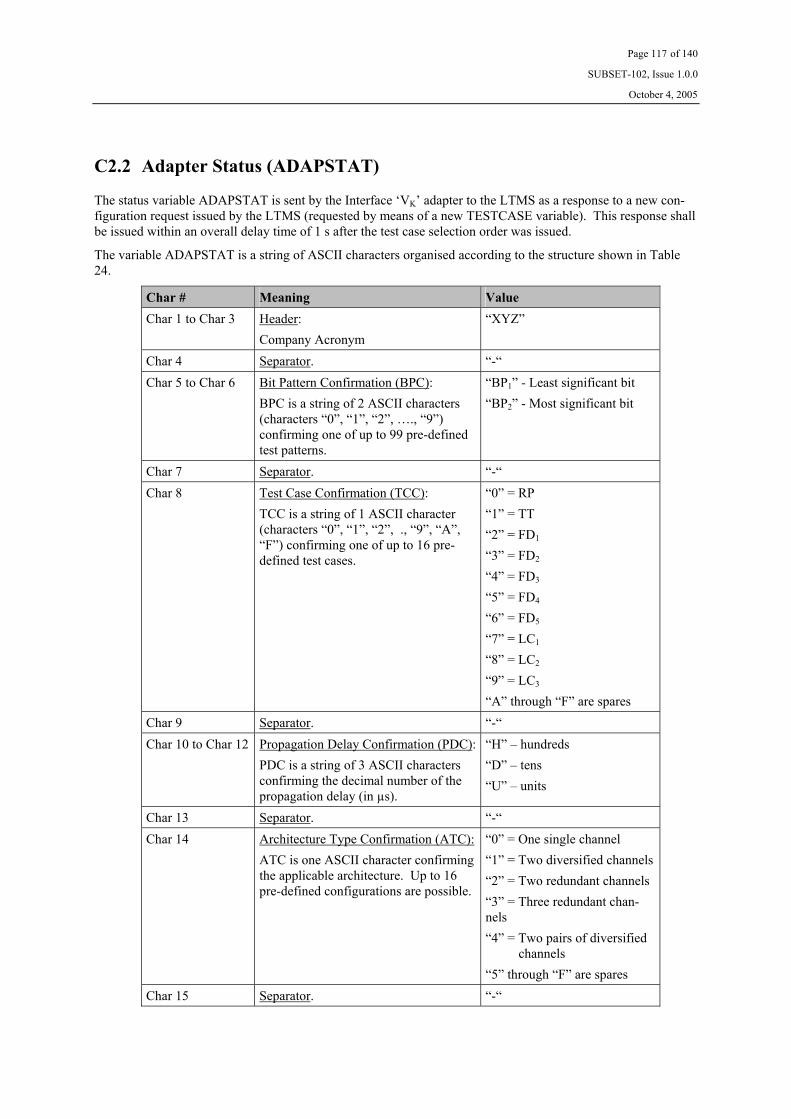
Page 117 of 140
SUBSET-102, Issue 1.0.0
October 4, 2005
C2.2 Adapter Status (ADAPSTAT)
The status variable ADAPSTAT is sent by the Interface ‘VK’ adapter to the LTMS as a response to a new con-figuration request issued by the LTMS (requested by means of a new TESTCASE variable). This response shall be issued within an overall delay time of 1 s after the test case selection order was issued.
The variable ADAPSTAT is a string of ASCII characters organised according to the structure shown in Table 24.
Char # Meaning Value Char 1 to Char 3 Header:
Company Acronym“XYZ”
Char 4 Separator. “-“ Char 5 to Char 6 Bit Pattern Confirmation (BPC):
BPC is a string of 2 ASCII characters (characters “0”, “1”, “2”, …., “9”) confirming one of up to 99 pre-defined test patterns.
“BP1” - Least significant bit “BP2” - Most significant bit
Char 7 Separator. “-“ Char 8 Test Case Confirmation (TCC):
TCC is a string of 1 ASCII character (characters “0”, “1”, “2”, ., “9”, “A”, “F”) confirming one of up to 16 pre-defined test cases.
“0” = RP “1” = TT “2” = FD1 “3” = FD2 “4” = FD3 “5” = FD4 “6” = FD5 “7” = LC1 “8” = LC2 “9” = LC3
“A” through “F” are spares Char 9 Separator. “-“ Char 10 to Char 12 Propagation Delay Confirmation (PDC):
PDC is a string of 3 ASCII characters confirming the decimal number of the propagation delay (in µs).
“H” – hundreds “D” – tens “U” – units
Char 13 Separator. “-“ Char 14 Architecture Type Confirmation (ATC):
ATC is one ASCII character confirming the applicable architecture. Up to 16 pre-defined configurations are possible.
“0” = One single channel “1” = Two diversified channels “2” = Two redundant channels “3” = Three redundant chan-nels “4” = Two pairs of diversified
channels “5” through “F” are spares
Char 15 Separator. “-“

Page 118 of 140
SUBSET-102, Issue 1.0.0
October 4, 2005
Char # Meaning Value Char 16 Data Type Confirmation (DTC):
DTC is one ASCII character confirming information on the applicable case.
“0” = Optimally decoded data is not provided
“1” = Optimally decoded data is provided
Char 17 Separator. “-“ Char 18 to Char 19 Link Check Extension Confirmation
(LCEC): LCEC confirms how many additional (optional) bits are included in the link check pattern. LCEC is a string of 2 ASCII character giving the decimal number. Zero means basic link check pattern.
“D” – tens “U” – units
Char 20 Separator. “-“ Char 21 Antenna/BTM ID Data Confirmation
(AIDC): AIDC confirms which Antenna/BTM ID Data is supposed to be received. This is one ASCII character giving the information.
“0” = A1 set to 0 and A2 set to 0
“1” = A1 set to 1 and A2 set to 0 “2” = A1 set to 0 and A2 set to 1 “3” = A1 set to 1 and A2 set to 1
Table 24: ADAPSTAT variable structure

Page 119 of 140
SUBSET-102, Issue 1.0.0
October 4, 2005
C2.3 Link Status (ALIVE)
The status variable ALIVE is periodically sent by the Interface ‘VK’ adapter to the LTMS approximately every 5 s to confirm that the link with the LTMS is correctly working.
The correct behaviour of the link is indicated by a modulo 10 counter that is regularly incremented by 1 at each transmission. The status of this counter is contained in the ALIVE variable sent to the LTMS.
The ALIVE variable is a string of ASCII characters organised according to the structure shown in Table 25.
Char # Meaning Value Char 1 to Char 3 Header:
Company Acronym“XYZ”
Char 4 Mod. 10 counter: Current value
“0”, “1”, “2”,.., “9”.”0” …
Table 25: ALIVE variable structure
C3 Test Data C3.1 Test Report (TEST_REP)
After receiving data transmitted via Interface ‘K’, the adapter shall evaluate the correctness and consistency of the data, and transmit the result to the LTMS via Interface ‘VK’. There is a need for two different responses from the interface adapter dependent on which test case is in progress.
For test cases RP and TT, there should be a periodic transmission every reporting period including:
• Number of correct bits within the reporting interval
This consists of transmission of ASCII characters and constitutes the overall number of non-overlapping correct bits received between two subsequent reports to the LTMS (not the accumulated number of bits).
For all other test cases, there should be a periodic transmission every reporting period consisting of transmission of ASCII characters, where the characters represent:
• ERTMS Unavailable (true/false)
• Eurobalise Reception (true/false)
• Erroneous Link ID (true/false)
• Erroneous Antenna/BTM ID (true/false)
• Erroneous Bit Counter (true/false)
• Erroneous CRC (true/false)
• Permanent Failure (true/false)
• Link Check OK (true/false)
• FD1 test OK (true/false)
• Signal Strength Data

Page 120 of 140
SUBSET-102, Issue 1.0.0
October 4, 2005
The LTMS checks the logical consistency between the various fields of the TEST_REP variable transmitted by the Interface ‘VK’ adapter.
The reporting period, could range between 50 ms and 600 ms.
The Interface ‘VK’ adapter evaluates and converts the data, received from the Interface ‘K’, to the format pre-scribed for the TEST_REP variable, and then transmits it to the LTMS. The LTMS should have an internal buffering capability, in order to allow the LTMS to possibly postpone the on-line data elaboration, when it has to handle more urgent tasks than the Interface ‘VK’ communication. The buffering is assumed to be dimen-sioned such that at least 20 s of test data can be received without losses, even when the interface adapter con-tinuously transmits data for a prolonged time. The buffering can be of circular type. This implies that, during a continuous flow of test data, some of the data older than 20 s, can sporadically be lost by the LTMS.
In case the adapter is set in the mode of Radiation Pattern (RP) or Transmission Tests (TT), the TEST_REP_A variable is a string of ASCII characters organised according to the structure shown in Table 26.
Char # Meaning Value Char 1 to Char 3 Header:
Company Acronym“XYZ”
Char 4 Separator. “-“ Char 5 to Char 8 Number of non-overlapping correct bits (CB):
CB is a string of 4 ASCII characters giving the decimal number of received telegrams.
“M” – thousands “H” – hundreds “D” – tens “U” – units
Table 26: TEST_REP_A variable structure for RP and TT cases

Page 121 of 140
SUBSET-102, Issue 1.0.0
October 4, 2005
In case the adapter is set in any other mode than Radiation Pattern (RP) or Transmission Tests (TT), the TEST_REP_B variable is a string of ASCII characters organised according to the structure shown in Table 27.
Char # Meaning Value Char 1 to Char 3 Header:
Company Acronym“XYZ”
Char 4 Separator. “-“ Char 5 ERTMS Unavailable:
True/false “0” = false “1” = true
Char 6 Eurobalise Reception: True/false
“0” = false “1” = true
Char 7 Erroneous Link ID: True/false
“0” = false “1” = true
Char 8 Erroneous Antenna/BTM ID: True/false
“0” = false “1” = true
Char 9 Erroneous Bit Counter: True/false
“0” = false “1” = true
Char 10 Permanent Failure: True/false
“0” = false “1” = true
Char 11 Link Check OK: True/false
“0” = false “1” = true
Char 12 FD1 test OK: True/false
“0” = false “1” = true
Char 13 to Char 14 Signal Strength Data (SS): SS is a string of 2 ASCII characters giving the deci-mal representation of the reported signal strength (range 0 through 15).
“D” – tens “U” – units
Table 27: TEST_REP_B variable structure for all cases except RP and TT

Page 122 of 140
SUBSET-102, Issue 1.0.0
October 4, 2005
C4 Physical Control C4.1 General
The media for Interface ‘VK’ shall be two twisted shielded pairs of wires. The nominal characteristic impedance of the cable shall be 120 Ω.
The interfaces shall fulfil the requirements of the RS485 standard.
The connector layout and the disposition of the connector in the interface adapter may be dependent on the actual selection of commercial hardware.
C4.2 Architecture
The following general architecture applies for connecting the On-board system under test to the test environment via Interface ‘VK’.
Interface ‘K’
Antenna Unit
ERTMS/ETCSKernel
‘A’
Interface ‘VK’
Adapter
Interface ‘VK’
On-board Transmission
Equipment
ERTMS/ETCS On-board
Constituent
BTM functionLTMS
Figure 20: Architecture
The data to be exchanged between the Interface ‘VK’ adapter and the test environment (in this case the LTMS) is defined in chapter C2 on page 114 and chapter C3 on page 119.
In general, interaction via Interface ‘VK’ is defined through the following variables:
• Test Case Selection • Adapter Status • Link Status • Test Report
The variables are of various lengths, and no checksum mechanism is defined on that level. The variables are transmitted on a one by one basis at various repetition rates or instants.

Page 123 of 140
SUBSET-102, Issue 1.0.0
October 4, 2005
C4.3 Interface ‘VK’, Mechanical Data
DSUB connectors with 9 pins/sockets shall be used.
Connector layout:
Interface Adapter side 7 LTMS side
Pin Signal Pin Signal
Positive Adapter Transmit terminal 1 Ground
Negative Adapter Transmit terminal 2 Ground
Ground 3 Unconnected
Positive LTMS Transmit terminal 4 Positive Adapter Transmit terminal
Negative LTMS Transmit terminal 5 Negative Adapter Transmit terminal
6 Unconnected
7 Unconnected
8 Positive LTMS Transmit terminal
9 Negative LTMS Transmit terminal
Table 28: Pin Configuration for Interface ‘VK’
The cable connector in the LTMS end of the cable shall be of female type.
The cable connector in the Interface Adapter end of the cable shall be of male type.
Note: Adequate termination shall be performed in the LTMS (a load resistor shall be connected between pins 4 and 5 of the LTMS cable connector).
7 The actual configuration with respect to pinning and disposition of the connector in the Interface Adapter may be de-
pendent on the actual selection of commercial hardware.

Page 124 of 140
SUBSET-102, Issue 1.0.0
October 4, 2005
RB0 V
RB RL
+5 V
RL
RB
RB
5
4
9
8
LTMS
Interface Adapter
+5 V
0 V
Figure 21: Physical Configuration for Interface ‘VK’
The load resistance RL shall be 110 Ω ±10 Ω.
The biasing resistors RB shall be 650 Ω ±30 Ω.
Please observe that the actual configuration with respect to pinning and disposition of the connector in the Inter-face Adapter may be dependent on the actual selection of commercial hardware. The load and biasing resistors indicated inside the Interface Adapter may also be external to the Interface Adapter (similarly to the LTMS side).

Page 125 of 140
SUBSET-102, Issue 1.0.0
October 4, 2005
C5 Link Control C5.1 General
The used communication channels shall be RS485. The applicable port configuration shall be:
• Data Rate 115.2 kbit/s
• Idle state of the channels at the high level (logical ‘one’)
• No Parity
• One start bit (a ‘zero’)
• 8 data bits (direct NRZ encoding)
• One stop bit (a ‘one’)
The channel for Interface ‘VK’ shall constitute full duplex communication. No handshaking shall be used.
C5.2 Interface ‘VK’
The variables defined in chapter C2 on page 114 and chapter C3 on page 119 shall be transmitted on a one by one basis. Each variable shall be preceded by a unique header, a sequence number, and information on length of data, and shall be succeeded by a 32-bit CRC. This is illustrated as follows.
Header(1 byte)
Length of Data(2 bytes)
Variable(X bytes)
CRC(4 bytes)
Seq. Number(1 byte)
The header before the package of variables (and before the ‘Length of Data’ and ‘Seq. Number’ fields) shall be one byte long and consist of a unique value for each variable as defined below.
The ‘Length of Data’ field shall be two bytes long and include the number of data bytes in the ‘Variable’ field (which in this case is as recalled below). The most significant byte shall be transmitted first.
The ‘Seq. Number’ field shall be one byte long and include a counter (individual for each variable) that is in-cremented by one each time the variable is transmitted. The variable shall be a modulo 256 counter (counting 0 to 255), which is initialised to zero at power on or if the interface adapter is reset.
The ‘Variable’ of the succeeding field has the following length, and shall be announced by the below defined header:
• Test Case Selection (TESTCASE) Header = 0 Length of Data = 17 (decimal)
• Adapter Status (ADAPSTAT) Header = 1 Length of Data = 21 (decimal)
• Link Status (ALIVE) Header = 2 Length of Data = 4 (decimal)
• Test Report (TEST_REP_A) Header = 3 Length of Data = 8 (decimal)
• Test Report (TEST_REP_B) Header = 4 Length of Data = 14 (decimal)
Page 126 of 140
SUBSET-102, Issue 1.0.0
October 4, 2005
The concluding ‘CRC’ shall be calculated over the overall bit stream of each transmission (i.e., the fields ‘Header’, ‘Seq. Number’, ‘Length of Data’, and ‘Variables’), before the inclusion of start and stop bits, using the following generator polynomial:
X32 + X30 + X27 + X25 + X22+ X20 + X13 + X12 + X11 + X10 + X8 + X7 + X6 + X5 + X4 + X0
For the purpose of initialisation of the 32 bit shift register for the generator polynomial, the pattern 0x00FF0000 (most significant bit …... least significant bit) applies.
The data flow is from most significant byte to least significant byte of each variable. The least significant bit is transmitted first for each byte.
If the LTMS detects the loss of data packages (using the ‘Seq. Number) or detects corruption of data (through evaluation of the CRC), it shall terminate the test that is in progress, and re-start the test.

Page 127 of 140
SUBSET-102, Issue 1.0.0
October 4, 2005
C6 Link Synchronisation C6.1 General
There are four different scenarios where the synchronisation mechanism applies:
• During an initial switching ON sequence. There are two possibilities:
• Case 1 – The Interface ‘VK’ adapter is switched on before the Interface ‘VK’ driver in LTMS
• Case 2 – The Interface ‘VK’ driver in LTMS is switched on before the Interface ‘VK’ adapter
• During re-starting scenarios. There are two possibilities:
• Case 3 – The Interface ‘VK’ driver in LTMS is re-started but the Interface ‘VK’ adapter remains on
• Case 4 – The Interface ‘VK’ adapter is re-started but the Interface ‘VK’ driver in LTMS remains on
The general mechanism used by the Interface ‘VK’ driver in LTMS to synchronise with the Interface ‘VK’ adapter is that for each ADAPSTAT, ALIVE, or TEST_REP variable, whose internal sequence number (i.e., the sequence number stored by the Interface ‘VK’ driver that is received from the Interface ‘VK’ adapter) is equal to 0, the Interface ‘VK’ driver updates itself with the sequence number (SN) received from the Interface ‘VK’ adapter. See also section C6.6 on page 131.
C6.2 The Interface Adapter is switched on before the Interface ‘VK’ driver
This is referred to as Case 1, and is the normal situation. As shown in Figure 22, the Interface ‘VK’ driver inter-nally synchronises with the ALIVE variable, thus modifying its sequence number.
Figure 22: Case 1
Interface Adapter is switched on
Interface ‘VK’ driver is switched on
‘VK’ driver expects SN equal to o for ALIVE
‘VK’ driver corrects its SN when receiving the ALIVE from the adapter
Interface Adapter VK

Page 128 of 140
SUBSET-102, Issue 1.0.0
October 4, 2005
C6.3 The Interface ‘VK’ driver is switched on before the Interface Adapter
This is referred to as Case 2, which is not a normal case because the interface adapter is normally switched on before the Interface ‘VK’ driver. However, it might happen, and then the interface adapter shall be able to syn-chronise with the Interface ‘VK’ driver. As shown in Figure 23, the Interface ‘VK’ driver waits for some time to receive the ALIVE status from the interface adapter. It gives a time out error after some time as no ALIVE variable has been received.
Figure 23: Case 2
Interface Adapter
Interface Adapter is switched on
Interface ‘VK’ driver is switched on
VK
Interface ‘VK’ driver shows a time out error after waiting for ALIVE status from the interface adapter

Page 129 of 140
SUBSET-102, Issue 1.0.0
October 4, 2005
C6.4 The Interface ‘VK’ driver is re-started but the Interface Adapter re-mains on
This case could happen sometimes. If a test procedure has finished and a new one is started, the interface adapter remains on whereas the Interface ‘VK’ driver is closed in the first test procedure and re-opened again in the second one. The Interface ‘VK’ driver needs to synchronise with the interface adapter.
As shown in Figure 24, the Interface ‘VK’ driver is re-started at some point of time. The first time the Interface ‘VK’ driver receives a variable from the interface adapter, the Interface ‘VK’ driver internally synchronises with the variable in a similar way as in Case 1. This normally happens with ALIVE, ADAPSTAT, and TEST_REP variables.
When the Interface ‘VK’ driver sends a TESTCASE variable after being re-started, the interface adapter is the one that synchronises with the Interface ‘VK’ driver as shown in Figure 25. The interface adapter does not an-swer with a ADAPSTAT variable the first time. This is due to synchronisation mechanism. The interface adapter needs a second TESTCASE variable to continue the communication.
Figure 24: Case 3, ALIVE variable
Interface Adapter VK
Interface Adapter is switched on
Interface ‘VK’ driver is switched on
Interface ‘VK’ driver stops
Interface ‘VK’ driver is switched on
‘VK’ driver expects SN equal to 0 for ALIVE
‘VK’ driver correct its SN when it receives the ALIVE from the interface adapter

Page 130 of 140
SUBSET-102, Issue 1.0.0
October 4, 2005
Figure 25: Case 3, TESTCONF variable
It should be considered that the Interface ‘VK’ adapter behaviour may depend on implementation. This descrip-tion only intends to clarify the behaviour of the Interface ‘VK’ driver.
Refer to the description of the synchronisation mechanism in section C6.6 on page 131 to understand all the possible situations.
C6.5 The Interface Adapter is re-started but the Interface ‘VK’ driver re-mains on
This case (referred to as Case 4) is an abnormal situation from the test procedure point of view. If the Interface ‘VK’ driver is active, this is because the test procedure is under execution. While the test procedure is running the interface adapter cannot be restarted. If the interface adapter is restarted during a test procedure, this is due to an interface adapter failure. In that case, the test procedure should stop and re-start again with a correctly operating interface adapter.
The interface adapter, and the Interface ‘VK’ driver, are re-started and synchronise according to Case 1.
Interface Adapter VK
Interface Adapter is switched on Interface ‘VK’ driver is switched on TESTCASE 0
TESTCASE 0
TESTCASE 1
ADAPSTAT 0
ADAPSTAT 1
ADAPSTAT 1
ADAPSTAT 0
Interface ‘VK’ driver stops
Interface ‘VK’ driver is switched on
ADAPSTAT Time Out
ADAPSTAT 0
TESTCASE 0
TESTCASE 0
TESTCASE 1
TESTCASE 1 Interface Adapter synchronises with VK and corrects its SN without sending an answer
Interface Adapter answers with a ADAPSTAT that is now synchronised
There is an ADAPSTAT time out error because the adapter does not answer
VK also synchronises with the new ADAPSTAT SN

Page 131 of 140
SUBSET-102, Issue 1.0.0
October 4, 2005
C6.6 Behaviour of the Interface ‘VK’ driver
The following behaviour is assumed to be implemented in the Interface ‘VK’ driver in the LTMS.
1. The Interface ‘VK’ driver sends a TESTCASE variable and waits for the corresponding ADAPSTAT variable from interface adapter.
If ADAPSTAT is received, the Interface ‘VK’ driver:
• Displays the received status in the button indicators.
• The first time (Interface ‘VK’ SN = 0), it does not check the SN of ADAPSTAT answer, but it updates its own SN with the new one coming from the interface adapter. No error is dis-played. In all the subsequent cases it checks the incoming SN and, if different from its own, it displays ”Stat Sequence Number” error.
• If ADAPSTAT has a status different from the requested TESTCASE status, there is an error message “ADAPSTAT error”, and the button indicators appear shaded.
• If ADAPSTAT is received outside the Time out, it displays “Stat Time out” error.
If ADAPSTAT is not received, the Interface ‘VK’ driver:
• Displays the error “Stat Time out”.
• Displays the error “ADAPSTAT error”.
2. The Interface ‘VK’ driver waits continuously for interface adapter alive status.
When ALIVE is received by the Interface ‘VK’ driver, it:
• Displays the three characters of the company acronym plus the “Mod 10 counter” in the ALIVE display.
• The first time (Interface ‘VK’ SN = 0) it does not check the SN of “Alive”, but it updates its own status with the new one coming from the interface adapter. No error is displayed. In all the subsequent cases, it checks the incoming SN and, if different from its own, it displays “Alive Sequence Number” error.
• The first time (Interface ‘VK’ SN = 0) it does not check the “Mod 10 counter” of ALIVE, it but it updates its own status with the new one coming from the interface adapter. No error is dis-played. In all the subsequent cases, it checks the incoming “Mod 10 counter” of “Alive” and, if different from its own, it displays “Alive Modulo 10” error.
• The first time (Interface ‘VK’ SN = 0) it does not check if it is received within ALIVE period + tolerance. No error is displayed. In all the subsequent cases, it checks if it is received within the Alive period + tolerance.
If ALIVE is not received or is received outside the Alive period ± tolerance, “Alive period” error is dis-played.
3. The Interface ‘VK’ driver continuously checks if TEST_REP is received from the interface adapter. When TEST_REP is received, the Interface ‘VK’ driver:
• Displays the received variable in the TEST_REP table.
• The first time (Interface ‘VK’ SN = 0) it does not check the SN of TEST_REP, but it updates its own status with the new one coming from the interface adapter. No error is displayed. In all the subsequent cases, it checks the incoming SN and, if different from its own, displays “Test Report Sequence Number” error.

Page 132 of 140
SUBSET-102, Issue 1.0.0
October 4, 2005
Annex D, Interface ‘K’ Adapter
D1 General The herein given suggestions constitute general architectural guidelines for designing the Interface ‘K’ adapter. The key issue is to facilitate short test time. Thus data transfer from a compute platform should be minimised and the transferred information should be such that hardware oriented modules should be able to select and repeat reasonably short pattern in order to generate the required sequences. Commercially available instruments are preferred as far as possible, but certain modules most likely need to be specifically developed.
D2 Functional Requirements In order to facilitate testing as defined in chapter 5 of this specification, the Interface ‘K’ adapter needs to pro-vide the following functionality related to the alternative 1 interface:
• Generation of extreme ASK bit data rate
• Generation of extreme phase differences between channels
• Generation of extreme jitter in the Bi-phase Level clock generation
• Generation of correct and erroneous number of stop bits
• Generation of various combinations of “data” (BD, TD, EU, EB, LT, S, A, and L data)
• Generation of correct and erroneous Bit Counter data (B data)
• Generation of correct and erroneous CRC
• Generation of correct Link Check pattern
• Generation of Link Check pattern with corrupt CRC
• Generation of Link Check patterns with other imperfections in “data”
For supporting the alternative 2 interface, the following functionality needs to be provided:
• Generation of extreme ASK bit data rate
• Generation of extreme phase differences between channels
• Generation of extremes regarding the relation between “data” and “CLK”
• Generation of suitable “data”
• Generation of indication of Eurobalise
• Generation of link tests

Page 133 of 140
SUBSET-102, Issue 1.0.0
October 4, 2005
D3 Suggested Block Diagram, Alternative 1 The block diagram according to Figure 26 below is suggested for the Interface ‘K’ Adapter supporting the alter-native 1 interface. Please note that the architecture is tailored for enabling short test time.
RS 485 driver
Parallel/serial converter
CRC Generation Counter Clock
÷ m
÷ n
Buffer
Generator PC
Sequence with: Telegram, Length, Pause,
Error condition, Envelop,
Inhibit Link Check
Bi Phase Level encoder
Figure 26: Block Diagram for Interface ‘K’ Adapter
The items within the dashed “box” are probably specifically developed HW modules.
There will also be a need for a specific S/W tool that is able to automatically generate the sequences that should be loaded into the generator.

Page 134 of 140
SUBSET-102, Issue 1.0.0
October 4, 2005
Annex E, Tools needing extended functionality
E1 General The majority of the tools are already defined in the documentation for Eurobalise (UNISIG SUBSET-085). However, some of the existing tools need extended functionality in order to facilitate testing of the Interface ‘K’ functionality.
This annex details what additional functionality and requirements are required for the already existing tools.
E2 Laboratory Management System (LTMS) E2.1 General
The herein defined additions apply to UNISIG SUBSET-085 in order to support the functionality required by the LTMS for the testing defined in this specification.
In general terms, the LTMS needs bidirectional communication with the Interface ‘VK’ adapter in order to set the adapter to required modes/status, and to receive test results.
E2.2 External Interfaces
The LTMS needs a new external interface for communicating with the Interface ‘VK’ adapter. This interface is similar to the existing interface with the Interface ‘V1’ adapter, but other information is communicated. The interface is defined in Annex C on page 114.
E2.3 Test Sequences
The LTMS needs to provide new test sequences with related evaluation supporting the test procedures defined herein, supporting the Interface ‘VK’ as defined in Annex C on page 114, and supporting the principles applica-ble to the Interface ‘VK’ adapter as defined in Annex F on page 136.

Page 135 of 140
SUBSET-102, Issue 1.0.0
October 4, 2005
E3 Reference Signal Generator (RSG_1) E3.1 General
The herein defined additions apply to UNISIG SUBSET-085 in order to support the functionality required by the RSG_1 for the testing defined in this specification.
In general terms, additional signals are needed for supporting generation of ASK Up-link signals and generation of suitable marker indicating transmission of a ‘zero’ ASK bit.
The RSG_1 needs to generate Up-link ASK test waveforms in addition to FSK test waveforms. The generation of the ASK patterns must be synchronised with the modulation pulses of the Tele-powering signal.
E3.2 External Interfaces
The RSG_1 needs to provide an additional marker suitably indicating the start of a ‘zero’ ASK bit. This marker shall be sent to the Interface ‘VK’ adapter.
The RSG_1 needs to receive a signal synchronising the generation of the Up-link signal with the modulation pulses of the Tele-powering signal from the On-board Equipment under test.
All this is defined in Figure 4 on page 16 and Figure 5 on page 16. Additionally, the delay between the modula-tion pulses in the air-gap and the generation and indication of the start of the ASK bit shall be adjustable within the RSG_1. See section 4.1.7 on page 24.
E3.3 Required Performance
The RSG_1 needs to support the ranges specified in UNISIG SUBSET-100 with respect to the following ASK specific parameters:
• Up-link Carrier Frequency
• Decay time t50
• Amplitude Jitter
• Delay Time tpudelay (please observe that synchronisation with the modulation pulses of the Tele-powering signal is required)
• Data Rate (50 kHz, synchronised with the modulation pulses of the Tele-powering signal)
The static synchronisation between the modulation pulses in the Tele-powering signal and the generation of the ASK bit pattern shall be better than 50 ns <TBC>, and the maximum allowed jitter in the generation of the data shall be better than 5 ns <TBC>.

Page 136 of 140
SUBSET-102, Issue 1.0.0
October 4, 2005
Annex F, Interface ‘VK’ Adapter
F1 General This annex details the requirements and functionality related to the Interface ‘VK’ adapter.
F2 Functional Requirements F2.1 General
The herein stated test cases are further defined in sections 4.2.4 trough 4.2.6 of this specification.
The Interface ‘VK’ adapter shall comply with the requirements defined for Interface ‘VK’ in Annex C on page 114.
The Interface ‘VK’ adapter shall comply with the applicable requirements defined for Interface ‘K’ in UNISIG SUBSET-101. Since there are two alternative interfaces, the adapter may either be realised as one dedicated to the so-called Alternative 1, and another to Alternative 2, or both alternatives may be integrated in the same adapter.
The Interface ‘VK’ adapter shall support the full scope of architecture variants defined in UNISIG SUBSET-101.
F2.2 Radiation Pattern Test and Transmission Tests
During “Radiation Pattern test” and “Transmission Tests”, the adapter needs the information that these tests are commanded by the LTMS, and must be given the possibility to periodically report the number of correctly re-ceived bits during the contact between the Reference Loop and the On-board equipment.
Therefore, the LTMS shall communicate the test cases “Radiation Pattern” or “Transmission Test” to the adapter, together with the information on the bit sequences intended to be transmitted. The bit sequence infor-mation shall be communicated in order to make it possible for the adapter to evaluate the response from the ERTMS equipment.
The adapter shall provide periodical reporting of “Number of correctly received bits” (e.g., each 100 ms period). This specific periodical reporting shall be linked to when the adapter is ordered into either “Radiation Pattern test” or “Transmission Tests” modes.

Page 137 of 140
SUBSET-102, Issue 1.0.0
October 4, 2005
F2.3 Functional Data Tests
The functional data tests are split into five different sub-tests requiring various needs of functionality and com-munication. These are:
• Functional Data case 1 (FD1)
• Functional Data Tele-powering off (FD2)
• Functional Data Eurobalise Reception (FD3)
• Functional Data Up-link off (FD4)
• Functional Data Permanent Error (FD5)
Regarding FD1, information on the intended bit pattern, and on the test case “FD1”, need to be communicated to the adapter. The adapter also needs to be suitably triggered by the RSG in order to be able to evaluate a specific instant where ‘one’ and ‘zero’ data is expected. The adapter also needs to get the information on the actual propagation delay from the air gap to Interface ‘K’ (evaluated in a previous test).
The adapter shall perform the evaluation defined in the first step of section 4.2.4.4 on page 30 or section 4.3.4.4 on page 59 (dependent on which interface alternative apply), and communicates “FD1 test OK” together with the actual Signal Strength value.
Regarding FD2, information on the test case “FD2”, needs to be communicated to the adapter. The LTMS switches the Tele-powering off (via Interface ‘V1’) and shall receive “ERTMS Unavailable” information from the interface adapter within no more than approximately 1 s (a reasonable observation interval for test purposes).
Regarding FD3, information on the test case “FD3”, needs to be communicated to the adapter. The LTMS starts transmitting FSK Up-link signal, and shall receive “Eurobalise Reception” as a response. The adapter shall by itself evaluate when FSK reception starts, and also evaluate the defined timing requirements related to when the ERTMS has recognised that Eurobalise reception is in progress.
Regarding FD4, information on the test case “FD4”, needs to be communicated to the adapter. The LTMS starts the sequence with transmitting Up-link signals, and switches the transmission off at suitable instant. The adapter shall recognise when transmission is aborted, and shall verify that correct link check pattern is received within 250/500 ms (dependent on which interface alternative apply). If this criterion is fulfilled, the information on “Link Check OK” shall be transmitted to the LTMS.
Regarding FD5, information on the test case “FD5”, needs to be communicated to the adapter. The test will be performed in a semi manual way such that the LTMS orders the operator to introduce a suitable error (e.g., unplugging the antenna). Thereafter, the adapter shall transmit “Permanent Error” to the LTMS when it has detected that there is no activity on Interface ‘K’. A reasonable observation interval for test purposes is 1 s (after the actual introduction of the failure).
During these tests, the adapter shall perform periodical reporting (e.g., each 100 ms period), communicating the appropriate information as defined in section C3.1 on page 119.

Page 138 of 140
SUBSET-102, Issue 1.0.0
October 4, 2005
F2.4 Link Check Functionality Tests
The link check functionality tests are split into three different sub-tests requiring various needs of functionality and communication. These are:
• Normal Link Check (LC1)
• Link Check with ASK (LC2)
• Link Check with FSK (LC3)
Regarding LC1, information on the test case “LC1”, needs to be communicated to the adapter. The adapter shall perform the evaluation that correct link test patterns are received according to the definitions of UNISIG SUBSET-101 and the definitions within this specification. The interface adapter shall communicate “Link Check OK” as long as the criteria are fulfilled (and otherwise “Link Check NOK”).
Regarding LC2, information on the intended bit pattern, and on the test case “LC2”, need to be communicated to the adapter. The LTMS also orders transmission of “continuous” ASK Up-link signal. The adapter shall per-form the evaluation and reporting as defined for functional data FD1, and shall verify that Balise data reception is aborted by a correct link check pattern after a time greater than 0.5 s but no later than 1 s after the start of the test. In the reporting interval succeeding the instant when the link check pattern was correctly detected, the adapter shall transmit “Link Check OK” to the LTMS. “Link Check NOK” shall be transmitted during Balise reception and in case no correct link check is detected (both in terms of pattern and in terms of timing).
Regarding LC3, the mechanisms are identical to LC2 with the exception that FSK Up-link signal is transmitted.
During these tests, the adapter shall perform periodical reporting (e.g., each 100 ms period), communicating the appropriate information as defined in section C3.1 on page 119.

Page 139 of 140
SUBSET-102, Issue 1.0.0
October 4, 2005
F3 Physical requirements F3.1 Interface ‘K’ Connectors
DSUB connectors of male type with 9 pins shall be used in the Interface ‘VK’ adapter.
Connector layout:
Interface ‘VK’ Adapter side
Pin Signal
4 Positive Adapter Receive terminal
5 Negative Adapter Receive terminal
3 Ground
8 Load Connection
9 Load Connection
6 Positive Adapter Receive terminal
7 Negative Adapter Receive terminal
Table 29: Pin Configuration for Interface ‘K’
Note that this pinning applies to a specific RS 485 board. Other boards may be selected, and the pinning could be suitable re-defined. However, in this case a suitable adapter shall be provided enabling the pinning of Table 29.
4
6
9
8
RL
RB
RB
ERTMS/ETCS
Interface Adapter
+5 V
0 V
5
7
Figure 27: Physical Configuration for Interface ‘K’
The load resistance RL shall be 110 Ω ±10 Ω.
The biasing resistors RB shall be 650 Ω ±30 Ω.

Page 140 of 140
SUBSET-102, Issue 1.0.0
October 4, 2005
F3.2 Connector for trigger from RSG_1
A standard chassis BNC connector shall be used.
F4 Electrical requirements F4.1 General
The Interface ‘VK’ adapter serial channels shall comply with the requirements of RS 485.
F4.2 Isolation
The input stages of the RS 485 receivers shall provide galvanic isolation between the device under test and the test environment.
F4.3 Trigger from RSG_1
The trigger signal from the RSG_1 is assumed to fulfil the following requirements.
• Pulse with low signal level of 0 V and high signal level of 2 V at 50 Ω load.
• Pulse width of 100 µs
• Rising edge is active edge.