test set, receiver ts-3565/trs-2 (v) (nsn 6625-01 · pdf filetest set, receiver ts-3565/trs-2...
TRANSCRIPT

TM 11-6625-2784-14
TECHNICAL MANUAL
OPERATOR’S, ORGANIZATIONAL, DIRECT SUPPORT,
AND GENERAL SUPPORT MAINTENANCE MANUALFOR
TEST SET, RECEIVER TS-3565/TRS-2 (V)(NSN 6625-01-075-0046)
This copy is a reprint which includes current
pages from Changes 1 and 2.
HEADQUARTERS, DEPARTMENT OF THE ARMY
29 July 1980

WARNINGHIGH VOLTAGE
is used in the associated test equipments.
DEATH ON CONTACTMAY RESULT IF SAFETY PRECAUTIONS
ARE NOT OBSERVED.Maintenance adjustments of this equipment are made with power applied, be carefulwhen working near the interior of the equipment, or near the ac power distribution wir-ing.
WARNINGAdequate ventilation should be provided while using TRICHLOROTRIFLUOROE-THANE. Prolonged breathing of vapor should be avoided. The solvent should not beused near heat or open flame the products of decomposition are toxic and irritating.Since TRICHLOROTRIFLUOROETHANE dissolves natural oils, prolonged contactwith skin should be avoided. When necessary, use gloves which the solvent cannotpenetrate. If the solvent is taken internally, consult a physician immediately.

CHANGE
No. 2
TM 11-6625-2784-14C 2
HEADQUARTERSDEPARTMENT OF THE ARMYWASHINGTON, DC, 17 August 1982
Operator’s, Organizational, Direct Support,and General Support Maintenance Manual
ForTEST SET, RECEIVER TS-3565/TRS-2(V)
(NSN 6625-01-075-0046)
TM 11-6625-2784-14, 29 July 1980, is changed as follows:
1. Remove old pages and insert new pages as indicated below. New or changed material is indicated by a vertical barin the margin of the page. Added or revised illustrations are indicated by a vertical bar adjacent to the identificationnumber.
Remove Insert
i and ii . . . . . . . . . . . . . . . . . . . . . . . . . . . . . . . . . . . . . . . . . . . . . . . . . . . . . . . . . . . . . . . . . . . . . . . i and ii
1-1 and 1-2 . . . . . . . . . . . . . . . . . . . . . . . . . . . . . . . . . . . . . . . . . . . . . . . . . . . . . . . . . . . . . . 1-1 and 1-2
3-1 through 3-6 . . . . . . . . . . . . . . . . . . . . . . . . . . . . . . . . . . . . . . . . . . . . . . . . . . . . . . . 3-1 through 3-6
5-1 and 5-2 . . . . . . . . . . . . . . . . . . . . . . . . . . . . . . . . . . . . . . . . . . . . . . . . . .. . . . . . . . . . 5-1 and 5-2
6-1 through 6-4 . . . . . . . . . . . . . . . . . . . . . . . . . . . . . . . . . . . . . . . . . . . . . . . . . . . . . . . . . . . . . 6-1 through 6-4
A-1/(A-2 Blank) . . . . . . . . . . . . . . . . . . . . . . . . . . . . . . . . . . . . . . . . . . . . . . . . . . . . . . A-1/(A-2 Blank)
2. File this change sheet in front of the publication manual for reference purposes.
By Order of the Secretary of the Army:
Official:
ROBERT M. JOYCEBrigadier General, United States Army
The Adjutant General
Distribution:
E. C. MEYERGeneral, United States Army
Chief of Staff
To redistributed in accordance with Special Mailing List.


TM 11-6625-2784-14C1
Change
No. 1
HEADQUARTERSDEPARTMENT OF THE ARMY
Washington, DC, July 1981
Operator’s, Organizational, Direct Support
And General Support Maintenance Manual
TEST SET, RECEIVER TS-3565/TRS-2(V)(NSN 6625-01-075-0046)
TM 11-6625-2784-14, 29 July 1980, is changed as follows:1. New or changed material is indicated by a vertical bar in the margin.2. Remove and insert pages as indicated below:
3. File this sheet in front of the manual for record purposes,
}

TM 11-6625-2784-14
By Order of the Secretary of the Army:
Official:
ROBERT M. JOYCEBrigadier General, United States Army
The Adjutant General
Distribution:Active Army:
HISA (Ft Monmouth (15)USAINSCOM (2)COE (1)TSG (1)USAARENBD (1)DARCOM (1)TRADOC (2)OS MAJ COMD (4)tercom (2)USACC (4)MDW (1)Armies (2)Corps (2)SVc Colleges (1)usasigs (5)USAADS (2)USAFAS (2)USAARMS (2)USAIS (2)
NG: State AG ( ): Units—NoneUSAR: None
E . C . M E Y E R
Genera l , Un i t ed S ta t e s Army
C h i e f o f S t a f f
USAES (2)USAICS (3)MAAG (1)USARMIS (1)USAERDAA (1)USAERDAW (1)Ft Carson (5)Ft Gillem (10)Ft Gordon (10)Ft Richardson (CERCOM Ofc) (2)USA Dep (1)Sig Sec USA Dep (1)Units org under fol TOE:
20-207 (2)29-610 (2)
For explanation of abbreviations used, see AR 310-50.

TM 11-6625-2784-14
TECHNICAL MANUAL
No. 11-6625-2784-14
HEADQUARTERSDEPARTMENT OF THE ARMYWASHINGTON , DC, 29 July 1980
OPERATOR, ORGANIZATIONAL, DIRECT SUPPORT,AND
GENERAL SUPPORT MAINTENANCE MANUALFOR
TEST SET, RECEIVER TS-3565/TRS-2(V)(NSN 6625-01-075-0046)
REPORTING ERRORS AND RECOMMENDING IMPROVEMENTSYou can improve this manual. If you find any mistakes or if you know of a way to improve the procedures,
please let us know. Mail your letter, DA Form 2028 (Recommended Changes to Publications and Blank Forms),or DA Form 2028-2 located in the back of this manual direct to: Commander, US Army Communication-Electronics Command, ATTN: DRSEL-ME-MQ, Fort Monmouth, NJ 07703. In either case, a reply will be fur-nished direct to you.
C H A P T E R 1.Section I.
II.
C HAPTER 2.
Section3.I .
II.
C HAPTER 4.
5.
Section6.I.
Paragraph
l-l1-21-2.11-31-41-51-5.1
1-61-71-8
2-12-2
3-1
3-23-33-43-53-6
4-14-24-3
5-15-2
6-16-2
Page
1-11-11-11-11-1l-l1-1
1-21-21-2
2-12-1
3-1
3-23-23-43-63-6
4-14-14-1
5-15-1
6-16-1
C h a n g e 2 i

TM 11-6625-2784-14
APPENDIX
Section
APPENDIX
Section
APPENDIX
Section
APPENDIX
Section
Figure1-12-13-13-23-33-43-55-16-16-26-3
II.
III.
IV.
A.B.I.
II.III.
C.I.
II.D.I.
II.E.I.
II.
ParagraphTroubleshootingGeneral . . . . . . . . . . . . . . . . . . . . . . . . . . . . . . . . . . . . . . . . . . . . . . . . . . . . . . . . . . . . . . . . . . . . . . . . . . . . . . . . . . . 6-3Troubleshooting Procedure. . . . . . . . . . . . . . . . . . . . . . . . . . . . . . . . . . . . . . . . . . . . . . . . . . . . . . . . . . . . . . . . . . 6-4Maintenance ProceduresRemoval and Replacement of Panel Mounted Components and Circuit Card Assembly . . . . . . . . . . . . . . . . 6-5Removal and Replacement of Battery Box Cover Assembly Handle . . . . . . . . . . . . . . . . . . . . . . . . . . . . . . . . 6-6Removal and Replacement of Battery Box Cover Assembly . . . . . . . . . . . . . . . . . . . . . . . . . . . . . . . . . . . . . . . 6-7Removal and Replacement of Battery Box Assembly . . . . . . . . . . . . . . . . . . . . . . . . . . . . . . . . . . . . . . . . . . . . . 6-8Removal and Replacement of Battery Box Gasket . . . . . . . . . . . . . . . . . . . . . . . . . . . . . . . . . . . . . . . . . . . . . . . 6-9Removal and Replacement of Test Set Case Pressure Relief Valve. , . . . . . . . . . . . . . . . . . . . . . . . . . . . . . . . . 6-10Repair of Test Cable #3 (Wire Module) . . . . . . . . . . . . . . . . . . . . . . . . . . . . . . . . . . . . . . . . . . . . . . . . . . . . . . . . 6-11Direct Support Test Procedure General . . . . . . . . . . . . . . . . . . . . . . . . . . . . . . . . . . . . . . . . . . . . . . . . . . . . . . . . 6-12Tests and Performance Standards . . . . . . . . . . . . . . . . . . . . . . . . . . . . . . . . . . . . . . . . . . . . . . . . . . . . . . . . . . . . . 6-13REFERENCES . . . . . . . . . . . . . . . . . . . . . . . . . . . . . . . . . . . . . . . . . . . . . . . . . . . . . . . . . . . . . . . . . . . . . . . . . . . .MAINTENANCE ALLOCATION CHART . . . . . . . . . . . . . . . . . . . . . . . . . . . . . . . . . . . . . . . . . . . . . . . . . . .Introduction . . . . . . . . . . . . . . . . . . . . . . . . . . . . . . . . . . . . . . . . . . . . . . . . . . . . . . . . . . . . . . . . . . . . . . . . . . . . . . .Maintenance Allocation Chart. . . . . . . . . . . . . . . . . . . . . . . . . . . . . . . . . . . . . . . . . . . . . . . . . . . . . . . . . . . . . . .Tool and Test Equipment Requirements for Test Set, Receiver TS-3565/TRS-2(V) . . . . . . . . . . . . . . . . . . . .Remarks . . . . . . . . . . . . . . . . . . . . . . . . . . . . . . . . . . . . . . . . . . . . . . . . . . . . . . . . . . . . . . . . . . . . . . . . . . . . . . . . . .COMPONENTS OF END ITEM AND BASIC ISSUE ITEMS LISTSIntroduction . . . . . . . . . . . . . . . . . . . . . . . . . . . . . . . . . . . . . . . . . . . . . . . . . . . . . . . . . . . . . . . . . . . . . . . . . . . . . . .Components of End Item. . . . . . . . . . . . . . . . . . . . . . . . . . . . . . . . . . . . . . . . . . . . . . . . . . . . . . . . . . . . . . . . . . . .ADDITIONAL AUTHORIZATION LISTIntroduction . . . . . . . . . . . . . . . . . . . . . . . . . . . . . . . . . . . . . . . . . . . . . . . . . . . . . . . . . . . . . . . . . . . . . . . . . . . . . . .Additional Authorization List . . . . . . . . . . . . . . . . . . . . . . . . . . . . . . . . . . . . . . . . . . . . . . . . . . . . . . . . . . . . . . . .EXPENDABLE SUPPLIES AND MATERIALS LISTIntroduction . . . . . . . . . . . . . . . . . . . . . . . . . . . . . . . . . . . . . . . . . . . . . . . . . . . . . . . . . . . . . . . . . . . . . . . . . . . . . . .Expendable Supplies and Materials List . . . . . . . . . . . . . . . . . . . . . . . . . . . . . . . . . . . . . . . . . . . . . . . . . . . . . . . .
LIST OF ILLUSTRATIONSTitle
Test Set, Receiver TS-3565/TRS-2(V) . . . . . . . . . . . . . . . . . . . . . . . . . . . . . . . . . . . . . . . . . . . . . . . . . . . . . . . . . . . . . . . . . . . . .Typical Packaging Diagram.. . . . . . . . . . . . . . . . . . . . . . . . . . . . . . . . . . . . . . . . . . . . . . . . . . . . . . . . . . . . . . . . . . . . . . . . . . . . .Test Set TS-3565/TRS-2(V) Front Panel Controls and Indicators . . . . . . . . . . . . . . . . . . . . . . . . . . . . . . . . . . . . . . . . . . . . . .Preliminary Test Setup . . . . . . . . . . . . . . . . . . . . . . . . . . . . . . . . . . . . . . . . . . . . . . . . . . . . . . . . . . . . . . . . . . . . . . . . . . . . . . . . . .Test Setup for Receiver Test (RF Mode) . . . . . . . . . . . . . . . . . . . . . . . . . . . . . . . . . . . . . . . . . . . . . . . . . . . . . . . . . . . . . . . . . . . .Test Set Data Switch Positions . . . . . . . . . . . . . . . . . . . . . . . . . . . . . . . . . . . . . . . . . . . . . . . . . . . . . . . . . . . . . . . . . . . . . . . . . . .Test Setup for Receiver Test (Wire Mode) . . . . . . . . . . . . . . . . . . . . . . . . . . . . . . . . . . . . . . . . . . . . . . . . . . . . . . . . . . . . . . . . . .Test Set Block Diagram . . . . . . . . . . . . . . . . . . . . . . . . . . . . . . . . . . . . . . . . . . . . . . . . . . . . . . . . . . . . . . . . . . . . . . . . . . . . . . . . .Troubleshooting Test Setup... . . . . . . . . . . . . . . . . . . . . . . . . . . . . . . . . . . . . . . . . . . . . . . . . . . . . . . . . . . . . . . . . . . . . . . . . . . .Test Set Data Signal (TP4Waveform) . . . . . . . . . . . . . . . . . . . . . . . . . . . . . . . . . . . . . . . . . . . . . . . . . . . . . . . . . . . . . . . . . . . . .Test Set Schematic Diagram. . . . . . . . . . . . . . . . . . . . . . . . . . . . . . . . . . . . . . . . . . . . . . . . . . . . . . . . . . . . . . . . . . . . . . . . . . . . . .
Page
6-16-1
6-56-56-56-56-56-66-66-66-6A-1
B-1B-3B-4B-5
C-1C-2
D-1D-2
E-1E-2
Page0-12-13-13-23-33-33-55-26-26-36-8
ii Change 2

TM 11-6625-2784-14
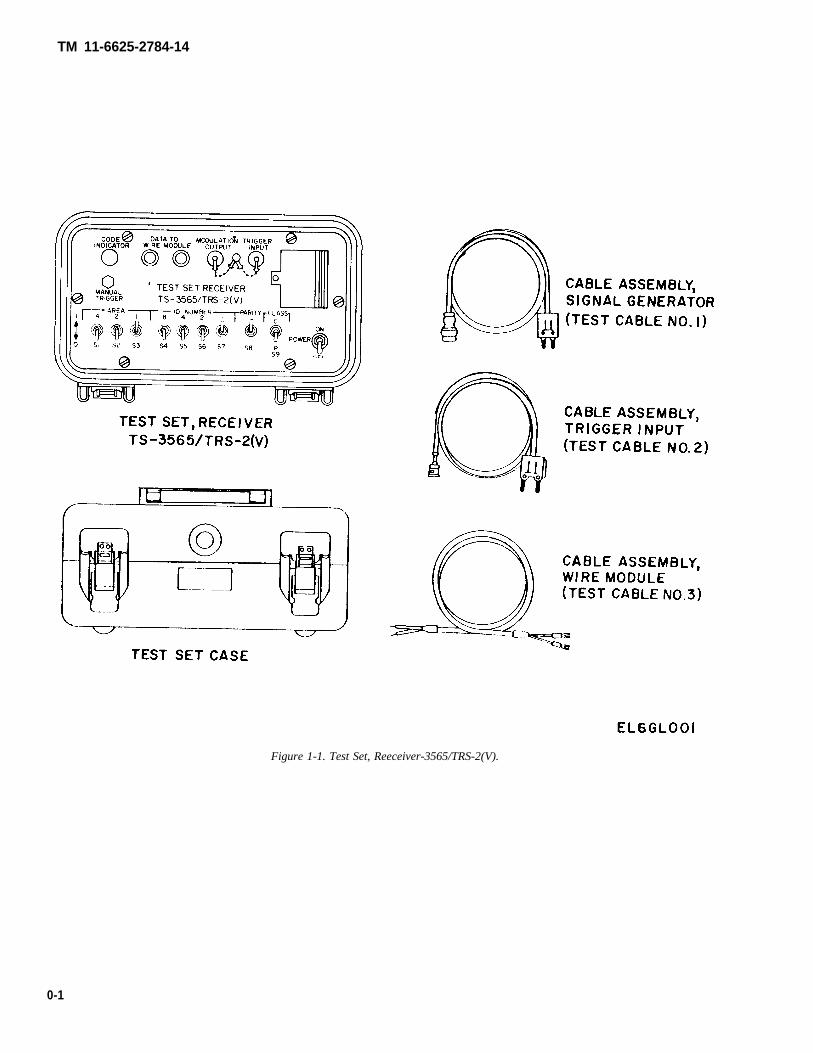
Figure 1-1. Test Set, Reeceiver-3565/TRS-2(V).
0-1

TM 11-6625-2784-14
CHAPTER 1INTRODUCTION
Section I. GENERAL
1-1. Scopea. This manual describes Test Set, Receiver TS-
3565/TRS-2(V) and covers its operation andmaintenance (fig. l-l).
b. Throughout this manual, references are made tomanuals which describe the installation, operation andmaintenance of Platoon Early Warning System (PEWS)AN/TRS-2(V). The TS-3565/TRS-2(V) is used tocheck Receiver, Radio R- 1808(V)/TRS-2(V). A listingof applicable references is provided in appendix A.
c. The Maintenance Allocation Chart appears in ap-pendix B, and the Components of End Item List ap-pears in appendix C.
NOTEUnless otherwise specified reference to theTS-3565/TRS-2(V), AN/TRS-2(V), R-1808(V)/TRS-2(V), and DT-577(V)/TRS-2apply to all variations.
d. Throughout this manual references are made tothe six variations of the PEWS. This also applies to theReceiver, Radio R-1808(V)/TRS-2(V). The variationsare as follows:
R-1808(V)l/TRS-2(V) 139.100 MHzR-1808(V)2/TRS-2(V) 139.250 MHzR-1808(V)3/TRS-2(V) 141.100 MHzR-1808(V)4/TRS-2(V) 148.925 MHzR-1808(V)5/TRS-2(V) 149.600 MHzR-1808(V)6/TRS-2(V) 150.600 MHz
1-2. Maintenance Forms, Records, andReports
a. Reports of Maintenance and UnsatisfactoryEquipment. Department of the Army forms and pro-cedures used for equipment maintenance will be thoseprescribed by TM 38-750, The Army MaintenanceManagement System.
b. Reporting of Packaging and Handling Deficien-cies. Fill out and forward SF 364 (Report of Discrepan-cy (ROD)) as prescribed in AR 735-1l-2/DLAR4140,55/NAVMATINST 4610.33B/AFR 400.54/MCO4430.3E.
c. Discrepancy in Shipment Report (DISREP) (SF361). Fill out and forward Discrepancy in ShipmentReport (DISREP) (SF 361) as prescribed in AR 55-38/-NAVSUPINST 4610 .33B/AFR 75-18/MCO
P4610.19C/DLAR 4500.15.
1-2.1 Index of Technical PublicationsRefer to the latest issue of DA Pam 310-1 to determinewhether there are new editions, changes or additionalpublications pertaining to the equipment.
1-3. Destruction of Army Materiel toPrevent Enemy Use
Destruction of Army electronic materiel to preventenemy use shall be in accordance with TM 750-244-2.
1-4. Administrative StorageAdministrative storage of equipment issued to and usedby Army activities will have preventive maintenanceperformed in accordance with the PMCS charts beforestoring. When removing the equipment from ad-ministrative storage the PMCS should be performed toassure operational readiness. Disassembly and repack-ing of equipment for shipment or limited storage arecovered in paragraph 3-6.
1-5. Reporting Equipment improvementRecommendations (EIR)
If the TS-3565/TRS-2(V) needs improvement, let usknow. Send us an EIR. You, the user, are the only onewho can tell us what you don’t like about your equip-ment. Let us know why you don’t like the design. Tell uswhy a procedure is hard to perform. Put it on an SF 368(Quality Deficiency Report). Mail it to Commander, USArmy Communications-Electronics Command, ATTN:DRSEL-ME-MQ, Fort Monmouth, New Jersey 07703.We’ll send you a reply.
1-5.1. Hand ReceiptThis manual has a companion document with a TMnumber followed by “- HR” (which stands for HandReceipt). The TM 11-6625-2784-14-HR consists ofpreprinted hand receipts (DA Form 2062) that list enditem related equipment (i.e., COEI, BII, and AAL) youmust account for. As an aid to property accountability,additional -HR manuals may be requisitioned from theUS Army Adjutant General Publications Center,Baltimore, MD, in accordance with the procedures inchapter 3, AR 310-2, and DA Pam 310-10-2.
Change 2 1 -1

TM 11-6625-2784-14
Section Il. DESCRIPTION AND DATA
1-6. Purpose and Use.a. Test Set, Receiver TS-3565/TRS-2(V), common-
ly referred to as the test set, is used with Platoon EarlyWarning System AN/TRS-2(V), specifically for ben-chtesting of Receiver, Radio R-1808(V)/TRS-2(V),commonly referred to as the receiver.
b. The test set is used to generate a frequency shiftkeyed (FSK) signal for checking the operation of thereceiver. When testing the receiver in its radio frequency(RF) mode, the test set is used to modulate RF SignalGenerator AN/URM-70, the output of which is con-nected to the receiver. In checking the receiver wiremode, the output of the test set is applied directly to thereceiver through a wire link.
1-7. Descriptiona. The test set is housed in a portable metal carrying
case. The cover of the carrying case is secured by twolatches and has a rubber gasket which creates an air-tight, watertight seal. An automatic relief valve is in-stalled on the front of the case and is used to equalize in-ternal and external pressures. A spring-loaded carryinghandle is mounted on top. The main panel of the test setis also sealed by a rubber gasket, and is secured to thecarrying case by six screws. A battery compartment isaccessed through a cover on the right side of the panel.A printed circuit card assembly, containing theoperating electronic components of the test set, ismounted beneath the panel inside the case.
b. Three test set cables are stored in a tray in thecover of the carrying case. The cables are identified as
follows:(1) Test Cable #1-Signal Generator(2) Test Cable #2-Trigger Input(3) Test Cable #3-Wire Module
1-8. Tabulated DataDimensions:
LengthWidthHeight
WeightOperating Temperature Range
Power Requirements
Battery Life (5070 Trigger Cycle)Output Type
Output Impedance (Modulationoutput)
Output Impedance (Wire Moduleoutput)
Output Level (Modulation Out-put)
Output Level (Wire Moduleoutput)
Environmental (Cover Open)Environmental (Cover Closed)
Data Clock RateData Message OutputData Message Coding
12 inches (30.48 cm) approx.91/2 inches (24. 13 cm) approx.6 inches (15.24 cm) approx.10 lbs. (5 kg) approx.–25°F to +125°F (–30°C to
+50°C)One BA-3090 or one BA-5090
Battery200 Hours, nominalFSK Data Signal, 1500 Hz ±
3% (Data Low) 1800 Hz ±3% (Data High)
1800 ohms, typical
5,000 ohms balanced, typical
1.8 volts peak-to-peak across1500 ohms 1.8 typical
1.0 volt peak-to-peak singleended across 31,000 ohms,typical
Drip and waterproofFully immersible to approx. 3
feet ( 1 meter of water)33.33 Hz ± 3%9 bits + start bitS e l e c t a b l e b y i n d i v i d u a l
switches
1-2 Change 2

TM 11-6625-2784-14
CHAPTER 2SERVICE UPON RECEIPT AND INSTALLATION
2-1. Unpacking.a. Packaging Data. The test set is completely assem-
bled and packed in a corrugated carton when received. Atypical packing arrangement is shown in figure 2-1.
b. Removing Contents.(1) Position carton with its top facing UP.(2) Open the carton and remove the pads from the
top and sides.(3) Lift the test set from the carton by grasping and
lifting the handle on the top of the carrying case, saveshipping carton and packing materials.
2-2. Checking Unpacked Equipment.a. Inspect the equipment for damage incurred during
shipment. If the equipment has been damaged, report the
damage on DD Form 6.b. Check the equipment against the component listing
in appendix C, and the packing slip to see if the shipmentis complete. Report all discrepancies in accordance withthe instructions of TM 38-750. The equipment can beplaced in service even though a minor assembly or part,that does not affect proper functioning, is missing.
c. Check to see whether the equipment has beenmodified. (Equipment which has been modified will havethe Modification Work Order (MWO) number on thecase near the nomenclature plate.) Check also to seewhether all currently applicable MWO’s have been ap-plied. (Current MWO’s applicable to the equipment arelisted in DA Pam 310-7.)
Figure 2-1. Typical Packaging Diagram.
2-1


TM 11-6625-2784-14
CHAPTER 3OPERATING INSTRUCTIONS
Section I. CONTROLS AND INSTRUMENTS
3-1. Operator’s Control. described in table 3-1. The control panel is shown in figureThe controls and indicators of the test set are listed and 3-1.
Figure 3-1. Test Set TS-3565/TRS-2(V) Front Panel Controls and Indicators.
Table 3-1. Operator’s Controls and Indicators
Item No.Fig. 3-1
12345678
Control, Indicator or Connector
BATTERY COMPARTMENT hinged coverPOWER ON/OFF toggle switchAREA toggle switches S1, S2 and S3ID NUMBER toggle switches S4, S5, S6, S7PARITY toggle switch S8CLASS toggle switch S9MANUAL TRIGGER pushbutton switchCODE INDICATOR LED indicator
9 DATA TO WIRE binding posts (2)
10 MODULATION OUTPUT BNC receptacle
11 TRIGGER INPUT BNC receptacle
Function
Houses battery used to power test set.Turns the test set on and off.Used to encode the area number in the data message.Used to encode the ID number in the data message.Used to encode the parity bit in the data message.Used to encode the classification bit in the data message.Triggers a single data message when pressed.Shows that a data message is being produced and that the
battery is functioning.Provides the data signal for operating the Sensor Inter-
face, Wire Link MX-9738/TRS-2(V).Provides the data signal output for modulating the FM
signal generator.Allows connection of an external repetitive trigger signal.
3-1

TM 11-6625-2784-14
Section II.
3-2. Preliminary StartingNOTE
OPERATION
Procedures
Signal Generator AN/URM-70 should beallowed to warm up for approximately twohours before performing any tests.
a. Place the test set on the bench, unfasten thelatches which hold the cover, and remove.
b. Remove the three cable assemblies stored in thecover.
c. Open the battery compartment on the front of thetest set panel and install a BA-3090 or BA-5090. Closethe battery compartment cover.
d. Position the PEWS receiver to be tested, the
UNDER USUAL CONDITIONS
Signal Generator AN/URM-70, and the ElectronicCounter AN/USM-207 on the test bench. Using testcable #l (signal generator), connect the output of SignalGenerator AN/URM-70 to Electronic Counter AN/USM-207 as shown in figure 3-2.
e. Set the controls of Signal Generator AN/URM-70 as follows:
Control Position—
DEV. MULT switch X1MODULATION OFFPOWER ONFREQ. RANGE 100-200DEVIATION Approx. 50% of rotation
OUTPUT\
Figure 3-2. Preliminary Test Setup.
f. Set the controls of Electronic Counter AN/USM-207 as follows:
Control I Position
SENSITIVITYFUNCTIONGATE TIMEDISPLAYPOWERMixing Frequency SelectorConverter Attenuator SwitchesDirect/Hetrodyne Switch
PLUG-INFREQ103
Approx. 9 o’clock or as desiredSTORE100Both to leftHetrodyne
3-3. Initial AdjustmentsThe following procedures are performed to ensure thatthe output frequency of the signal generator matches the
receiver frequency.a. Adjust the output level of the signal generator so
that the level meter of the electronic counter reads in thegreen area.
b. Determine the frequency of the receiver from thenomenclature plate.
c. Using the TUNING and TRIMMER controls ofthe ANAJRM-70, adjust the signal generator output sothat the electronic counter display indicates the dif-ference frequency.
NOTEThe preceding procedures should be per-formed approximately every ten minutesduring receiver testing to ensure the signalgenerator remains set to the properfrequency.
3-2 Change 2

TM 11-6625-2784-14
Figure 3-3. Test Setup for Receiver Test (RF Mode).
Figure 3-4. Test Set Data Switch Positions.
3-3

TM11-6625-2784-14
3-4. Operating Procedurea. Receiver Test (RF Mode).
NOTEReceiver under test must have batteries in-stalled prior to performing the tests outlinedbelow.
(1) After performing the procedures in paragraph3-3, disconnect RF cable from electronic counter andconnect the test set, receiver, and signal generatorshown in figure 3-3 (using RF cable) and #2 (trigger in-put)).
(2) Set the MODULATION switch of the signalgenerator to the EXT. MOD position.
(3) Turn on the test set by setting the POWERON-OFF switch to the ON position.
(4) Adjust the DEVIATION control of the signalgenerator so that the DEVIATION meter reads 12 kHzdeviation on the yellow scale.
(5) Calibrate the OUTPUT control of the signalgenerator using the procedure described in theOperator’s Manual, TM 11-1258.
(6) Adjust the OUTPUT control of the signalgenerator to 0.4 microvolt.
(7) Set the AREA switch of the receiver beingtested to position #1 and make sure that the receiverDSPLTONE-OFF switch is set to the DSPL position.
(8) Set the data switches of the test set as in-dicated in figure 3-4.
(a) The 0 condition is achieved by placing thedesignated toggle switch in the DOWN position.
(b) The 1 condition is achieved by placing thedesignated toggle switch in the UP position.
(9) Press the MANUAL-TRIGGER button on thetest set and observe the display on the receiver. Thedisplay decimal points should momentarily light and thedisplay should read 1P.
(10) Adjust the output of the signal generator to 1microvolt.
(11) Perform (a) and (b) below for each in-dividual setting of the receiver AREA switch and test setdata switches listed in the chart below:
(a) Press the receiver TEST-RESET button.(b) Press the test set MANUAL-TRIGGER
button. On each one, the display on the receiver shouldread 1P.
(12) Set the receiver AREA switch to position #1.(13) Perform the following two procedures for
each individual setting of the test set data switches listedin table 3-2. In each case, the receiver LED displayshould agree with the characters indicated in the tablefor that combination of data switch positions.
(a) Press the receiver TEST-RESET button.(b) Press the test set MANUAL-TRIGGER
button. Check the characters on the receiver displayagainst those specified above.
(14) After checking displays for all settings listedin 13 above, press the TEST-RESET button on thereceiver.
(15) Press the MANUAL TRIGGER button on
the test set while watching the receiver display andlistening to the earphone. The display should read 16Cand decimal points should light on the display facemomentarily. At the same time, the alert tone should beheard in the earphone.
(16) Press the TEST RESET button on thereceiver. The display should go blank.
(17) Set the DSPL-TONE-OFF switch of thereceiver to the TONE position.
(18) While listening to the earphone, press theMANUAL TRIGGER button on the test set. The alerttone should be heard in the earphone.
(19) Turn the DSPL-TONE-OFF switch of thereceiver to the DSPL position. The display should read16C.
(20) After completing the above tests, turn thePOWER switches of all equipment to the OFF positionand disconnect cables.
3-4 Change 2

TM 11-6625-2764-14
Table 3-2. Test Set Data Switch Settings-Continued
Figure 3-5. Test Setup for Receiver Test (Wire Mode).
3-5

TM 11-6625-2784-14
NOTEIf an abnormal indication is observed duringany of the procedures, the receiver beingtested can be assumed to be defective andshould be forwarded to depot level repairpersonnel.
b. Receiver Test (Wire Link Mode).(1) Install the wire link on the bottom of the
receiver using the procedure described in TM 11-5895-1047-10.
(2) Connect the equipment as shown in figure 3-5using test cable #3. The cable should be connected to theNo. 1 screw terminals on the wire link. Wire polarity isnot important.
(3) Set the wire link REC-TEST switch to theREC position.
(4) Set the AREA switch of the receiver to posi-tion No. 1.
(5) Set the data switches of the test set as follows:
(6) Set the POWER ON-OFF switch on the testset to ON and the receiver DSPL-TONE-OFF switch toDSPL.
(7) Press the test set MANUAL-TRIGGER but-ton. The alert tone should be heard in the earphone; thedisplay decimal points should light momentarily and adisplay of 1 P should appear.(8) Repeat (1) through (7) above for each screw
terminal on the wire link. This consists of screw ter-minals 2 through 9.
NOTEIf the receiver is found to be operating cor-rectly in the RF mode but the proper displayis not obtained during wire link modetesting, the wire link can be assumed to bedefective.
3-5. Procedures for Shutdowna. Set the POWER ON-OFF switch on the test set to
OFF and the receiver DSPL-TONE-OFF switch to theOFF position.
b. Disconnect test cable #3 from the test set and wire
c. Remove wire link.d. Remove the batteries from the test set and
receiver, and replace battery compartment covers.e. Place the three test cables in the cover of the test
set for storage.f. Latch and secure the test cover to the case.
3-6. Preparation for Movementa. When the test set is to be moved to a new location
or placed in administrative storage, make sure that thecables are stored in the cover and that the battery hasbeen removed.
b. Clean the test set case with a dry cloth to removeloose dirt or dust.
c. Repackage the test set in the original shipping -
carton or package in a suitable container, ensuring thatdamage will not occur during transit.
3-6 Change 2

CHAPTER 4OPERATOR MAINTENANCE INSTRUCTIONS
4-1. General.The direct support repairer of the PEWS is considered tobe the operator of the test set. Operator maintenance islimited to inspection of the test set, cleaning, and replace-ment of the battery.
4-2. Routine Services.Routine services are performed by the operator at alltimes. Routine services are not listed in the PreventiveMaintenance Checks and Services Table 4-1, in order toseparate the non-operational checks from the operationalchecks. Routine services include cleaning, inspecting forbroken switches or knobs, and missing or unserviceablecables.
categories or intervals of PMCS: B, D, and A. They headthe interval columns of the PMCS table. A dot in one ormore of the interval columns indicates the check and/orservice that should be performed by the operator at a par-ticular time.
a. B stands for before. B-PMCS should be performedbefore operation to insure the equipment is operational.
b. D stands for during. D-PMCS are performed duringoperation to spot small problems before they become bigproblems.
c. A stands for after. A-PMCS are performed afteroperation to insure the equipment has not been damagedduring use.
d. Use your PMCS table to get the number for the TM4-3. Preventive Maintenance Checks and Item No. Column of DA Form 2404 (Equipment Inspec-
Services (PMCS). tion and Maintenance Work Sheet).Table 4-1 contains PMCS for the test set. There are three
Table 4-1. Operator Preventive Maintenance Checks and Services (PMCS)
INTERVAL PROCEDURES FOR READINESS REPORT-ITEM ITEM TO BE CHECK AND HAVE REPAIRED ING EQUIPMENT IS NOTNo. B D A W M INSPECTED OR ADJUSTED AS NECESSARY READY/AVAILABLE IF:
NOTE:The following test equipmentmust be used in performingPMCS on the test set:1. Operational PEWS2. Signal Generator AN/-URM-703. Frequency Counter AN/-USM-207
1 • • Test Set Check the completeness and operation of Upon completion of PMCS checks, test set isthe test set. inoperative.
2 • Test Set Install battery and set POWER ON-OFF CODE INDICATOR does not light whenswitch to ON. CODE INDICATOR power is applied.should light momentarily.
3 • Test Set Perform preliminary starting proceduresand initial adjustments as outlined in
4paragraphs 3-2 and 3-3.
• Perform receiver test (RF MODE) as out- Operational test or digital message test fails.lined in paragraph 3-4a.
5 • Test Set Perform receiver test (wire link MODE) as Operational teat or digital message test fails.outlined in paragraph 3-4b.
TM 11-6625-2784-14
4-1


TM 11-6625-2784-14
CHAPTER 5FUNCTIONING OF EQUIPMENT
5-1. General.The purpose and operation of the various circuits in thetest set are explained in this chapter. Familiarity with theequipment, how it works, and why it works are valuabletools for troubleshooting the equipment rapidly and effec-tively.
5-2. Functioning of Test Set, ReceiverTS-3565/TRS-2(V).
a. General Information. The test set is used to testReceiver, Radio R-1808(V)/TRS-2(V) in the RF mode
or in the wire link mode of operation. Interconnections foreach type of test are shown in figures 3-3 and 3-5. The testset generates two outputs. The MODULATION OUT-PUT is connected to a signal generator. The output of thesignal generator, routed to the receiver, is used to test theRF mode of operation. The DATA TO WIRE MODULE(balanced line) output, connected to the wire link, is usedto test the wire mode of operation. The switches on thetest set panel are used to select any area, ID or classifica-tion code for test transmission. Figure 5-1 is an overallblock diagram of the test set.
5-1

Figure 5-1. Test Set Block Diagram.

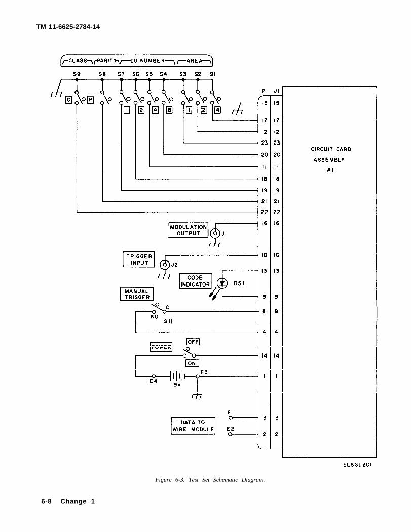
b. Input/Code Enable Circuits. The test set maybe trig-gered manually (using the MANUAL-TRIGGER but- ton) or by an external 5 volt pulse. A square wave genera-tor, used as the external trigger, is connected to theTRIGGER INPUT receptacle. The external input causescontinuous triggering of the test set. Signals from eitherthe manual or external trigger operate a trigger circuit. Atthis point, the trigger signal is used to set the latch circuitin the trigger conditioner which initiates the operation ofthe data generator. This condition continues until the ris-ing edges of the final data bit appears and the latch circuitin the trigger conditioner clears, This action disables thedata generator. The code enable circuit establishes thestart bit. The code enable circuit is able to develop an in-hibit signal to prevent the operation of the data generatorsystem. The reason for this inhibit signal is described in fbelow.
c. Data Generator. The data generator is composed ofa 100 Hz clock oscillator, a divide (+) by three stage, adata gate, a data multiplexer, and a pulse width modula-tor. The data generator develops the digital code used totest Receiver, Radio R-1808(V)/TRS-2(V).
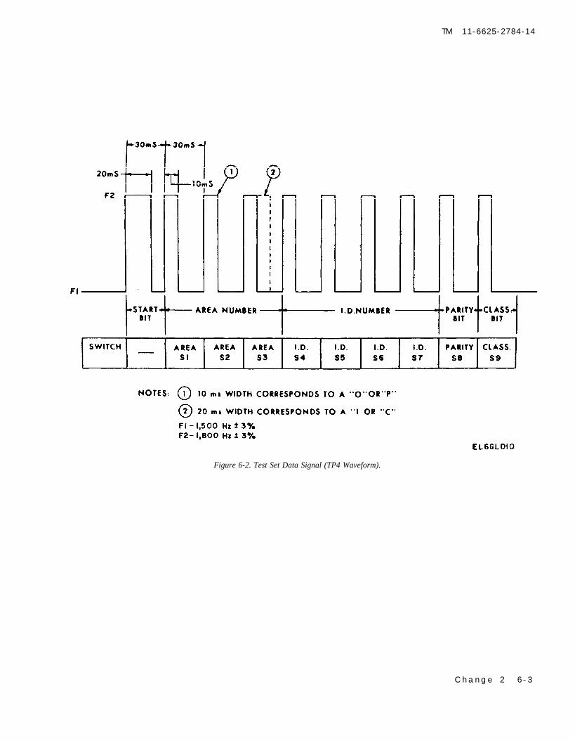
(1) The 100 Hz clock oscillator is composed of twogates in an astable configuration. The frequency is ad-justed by variable resistor R28. Test Point 1 (TP1)measures the 100 Hz oscillator input. While Test Point 2(TP2) is the output. Test Point 3 (TP3) is a ground con-nection.
(2) The output of the 100 Hz clock oscillator is ap-plied to the divide (+) by three circuit. The 33.33 Hz out-put drives the data multiplexer and the data gate. The datamultiplexer senses the condition of the nine data switches(AREA, ID NUMBER, PARITY, and CLASS), and pro-duces a train of pulses corresponding to the switch posi-
tions (closed or up = 1, open or down =0). This pulse trainis applied to the pulse width modulator.
(3) The pulse width modulator produces the base-band digital code used for transmission. The Pulse WidthModulated (PWM) code is a (30ms) bit period. With thefirst (10ms) always high, the second (10ms) high for a 1and low for a 0, and the third (10ms) always low. The out-put from the data generator can be measured at Test Point4 (TP4) .
d. Tone Generator. The 1500 Hz and 1800 Hz toneoscillator circuits are the same as the 100 Hz oscillator ex-cept the same component values are smaller. Variableresistor R37 adjusts the 1500 Hz oscillator, and variableresistor R39 adjusts the 1800 Hz oscillator. The 1500 Hzoscillator is enabled when the PWM data signal is low, andthe 1800 Hz oscillator is enabled when the data signal ishigh. The 1500 Hz tone is continuously present when nocode sequence is being sent, and the code sequence alwaysstarts by a change to 1800 Hz. The output of the 1500 and1800 Hz oscillators is a FSK data signal.
e. Output Circuits. The FSK output is then amplified bythe output amplifier to provide two outputs, one toMODULATION OUTPUT, and the other is applieddirectly to the DATA TO WIRE MODULE terminals.
f. Power Circuits. The 5.2 volt series regulator providespower to all circuitry except the code indicator. Thisregulator also includes a voltage comparator to determinewhen the battery voltage is too low to allow proper systemoperation. When a low battery condition is detected, aninhibit signal is sent to the input trigger circuit to preventoperation of the data generator system. During the periodthat data is being generated, an indicator located on thetop panel is lit. This indicates that the battery is good, andthe system is working properly.
5-3
TM 11-6625-2784-14


TM 11-6625-2784-14
CHAPTER 6DIRECT SUPPORT MAINTENANCE INSTRUCTIONS
Section L TOOLS AND EQUIPMENT
6-1. Tools Required maintenance of the test set:.Tools required for the test and repair functions Test Equipment National Stock Number
authorized by the maintenance allocation chart are con- 1. Multimeter, TS-352B/U 6625-00-553-01422. Counter, Electronic Digital 6625-00-911-6368
tained in Tool Kit, Electronic Equipment TK-105/G. Readout, AN/USM-207
6-2. Test Equipment Required 3. Signal Generator, AN/URM- 6625-00-519-210470
The following test equipment is required for 4. Oscilloscope, AN/USM-281C 6625-00-106-9622
Section Il. TROUBLESHOOTING
6-3. GeneralThe procedure, table 6-1, provides a step-by-stepmethod of checking the test set functions. It also pro-vides normal indications and suggested actions whichmay correct other than normal indications. Use table6-1, test equipment listed, and the schematic diagram,figure 6-3, to troubleshoot the equipment.
6-4. Troubleshooting ProcedureThe preliminary procedures listed below must be per-formed prior to troubleshooting the test set.
a. Place oscilloscope AN/USM-281C and Elec-
tronic Counter AN/USM-207 on the test bench, turnon, and allow a 15 minute warmup period.
b. Place test set on bench and prepare as follows:(1) Open cover.(2) Remove panel assembly by removing the six
panel screws.(3) Install battery.
c. Connect test equipment as shown in figure 6-1and perform the steps outlined in table 6-1.
d. Using the six panel screws, reinstall the panelassembly.
Change 2 6-1

TM 11-6625-2784-14
Figure 6-1. Troubleshooting Test Setup.
6-2 Change 2
TM 11-6625-2784-14
Change 2 6 -3
Figure 6-2. Test Set Data Signal (TP4 Waveform).

TM 11-6625-2784-14
Table 6-1. Fault Isolation and Correction Procedure
Step Procedure Normal lndication Corrective Action
1 Turn test set on and press MANUAL- The panel CODE INDICATOR lamp will Replace the test set battery and pressTRIGGER button of test set. light momentarily, MANUAL-TRIGGER button. If code
indicator lamp still does not lightreplace circuit board.
2
3
4
5
6
7
8
9
10
C A U T I O NBe careful when making connections around TP1 and TP3. If TP5 is accidentally shorted to ground, the power supplywill be damaged.
Connect a jumper lead between TP1 andTP3 on the test set circuit board. Connectthe oscilloscope and counter to TP2.
Disconnect jumper lead from TP1 and TP3.Disconnect oscilloscope and counter fromTP2. Connect oscilloscope to TP4.
Press the MANUAL-TRIGGER button onthe test set panel and adjust theoscilloscope sweep, vertical display sensi-tivity and triggering to display [he wave-form shown in figure 6-2. Set all paneldata switches (AREA, ID, PARITY, andCLASS.) to the down position. Initialsettings of the oscilloscope include:
NORM sweep, INT trigger, + slope, 50 mssweep, MAIN sweep, and 0.1 V/DIVsensitivity.
Progressively go through data switches fromleft to right (S1-S9) setting each of themto the UP position. Press the MANUALTRIGGER button after flipping eachswitch.
Disconnect oscilloscope from TP4. Connectoscilloscope and counter to the MODU-LATION OUTPUT receptacle. Place a1500 OHM resistor across the oscilloscopeto load the output.
Connect a jumper lead between TP4 andTP5 on the test set circuit board.
Disconnect the jumper lead, oscilloscope,and counter.
Connect the oscilloscope to data terminalpost E1. The oscilloscope ground can beattached to one of the BNC receptaclesor the dust cap lug.
Connect the oscilloscope to data terminalpost E2.
A 100 Hz (±1 H7) square wave will appearon oscilloscope. Frequency counter willindicate 100 Hz (±3 Hz).
Waveform shown in figure 6-2 will appeareach time MANUAL-TRIGGER buttonis pressed.
Bit width will change from 10 ms to 20 msas you progress to the right. Refer tofigure 6-2 to identify the particular bit thatcorresponds to each switch.
A 1500 Hz (±45 Hz) rounded square wavewith a peak-to-peak amplitude of at least1.2 volts will appear on oscilloscope. Fre-quency counter will indicate 1500 Hz(±45 Hz).
A 1800 Hz (±54 Hz) rounded square wavewith a peak-to-peak amplitude of at least1.2 volts will appear on the oscilloscope.Frequency counter will indicate 1800 Hz(±54 Hz).
A triangular wave with an amplitude greaterthan 0.8 volts peak-to-peak will appear onthe oscilloscope.
A triangular wave with an amplitude greaterthan 0.8 volts peak-to-peak will appear on
I the oscilloscope.
N O T E
Adjust resistor R28 on circuit board if fre-quency is out of tolerance. If no signalis seen, replace circuit board.
If no signal is seen, replace test set circuitboard.
If correct signal is not seen, replace testset circuit board.
Adjust resistor R37 on circuit board if fre-quency is out of tolerance. If no signalis seen, replace circuit board.
Adjust resistor R39 on circuit board if fre-quency is out of tolerance. If no signalis seen, replace circuit board.
If no signal is seen, replace the test setcircuit board.
If no signal is seen, replace the test setcircuit board.
A multimeter may be used to measure TP5 (supply voltage). Multimeter should read 5.2 VDC (±0.2 VDC). If less, replacebattery and measure again. If still less, or significantly greater than normal, replace PC assembly. TP6 (low voltage gate) mayalso be measured. TP6 must read less than 2 VDC. If greater, switch testing to oscilloscope. If still greater than 2 VDC,replace PC assembly.
6-4 Change 2

TM 11-6625-2764-14
Section Ill. MAINTENANCE PROCEDURES
6-5. Removal and Replacement of Panel MountedComponents and Circuit Card Assembly
a. Remove the six screws securing panel assem-bly to case and lift panel assembly out of case.
b. Loosen holding bracket and disconnect thecircuit card plug.
c. Remove the four screws securing circuit cardassembly to panel and remove circuit card.
d. Follow procedures listed below to removepanel components.
(1) Unsolder wires connected to defectivecomponent (switches, connectors, binding posts,and code indicator).
(2) Loosen and remove hardware securingcomponents to panel assembly.
(3) Install new component and reconnectwires.
e. Replace circuit card and panel assemblyremoved in a and b above.
f. Refer to paragraph 3-4 and perform opera-tional tests in insure test set is operational.
6-6. Removal and Replacement of Battery BoxCover Assembly Handle
a. Open battery box cover assembly.b. Remover retainer ring from bottom of battery
box cover assembly by spreading with a screw-driver and sliding it off the stud.
c. Remove stud and nylon washer from batterybox cover assembly.
d. Install a new nylon washer and a new stud inbattery box cover assembly.
e. Secure stud by sliding a new retainer ring onbottom of battery box cover assembly.
f. Close battery box cover assembly and tightenstud .
6-7. Removal and Replacement of Battery BoxCover Assembly
a. Remove six screws securingto case and remove.
b. Remove hardware securingto panel assembly.
c. Refer to paragraph 6-6 andcover handle.
d. Install new battery coversecure with hardware removed in b
e. Replace panel assembly andwith hardware removed in a above.
panel assembly
cover assembly
replace battery
assembly andabove.secure to case
6-8. Removal and Replacement of Battery BoxAssembly
a. Remove the six screws securing panel as-sembly to case and remove panel assembly.
b. Open battery box cover and remove thefour screws securing battery box assembly topanel assembly.
c. Install new battery box assembly on panelassembly as follows:
(1) Place battery box assembly over openingin panel assembly.
(2) Apply adhesive, thread locking to screwsand install three screws in panel assembly.
(3) Mount solder lug (part of battery boxassembly ) between battery box assembly andpanel assembly with remaining screw.
(4) Coat all screws with sealant, type III,Grade R.
d. Replace panel assembly and secure to casewith hardware removed in a above.
e. Install battery and refer to paragraph 3-4and perform operational tests to insure test setis operational.
6-9. Removal and Replacement of Battery BoxGasket
a. Follow the procedures in paragraph 6-8 toremove panel and battery box assemblies.
b. Remove unserviceable gasket.WARNING
ADEQUATE VENTILATION SHOULDBE PROVIDED WHILE USING TRI-CHLOROTRIFLUOROETHANE. PRO-LONGED BREATHING OF VAPORSHOULD BE AVOIDED. THE SOL-VENT SHOULD NOT BE USED NEARHEAT OR OPEN FLAME; THE PRO-DUCTS OF DECOMPOSITION ARETOXIC AND IRRITATING. SINCETRICHLOROTRIFLUOROETHANEDISSOLVES NATURAL OILS, PRO-LONGED CONTACT WITH SKIN SHO-ULD BE AVOIDED. WHEN NECES-SARY, USE GLOVES WHICH THESOLVENT CANNOT PENETRATE. IFTHE SOLVENT IS TAKEN INTERN-ALLY, CONSULT A PHYSICIAN IM-MEDIATELY.
c. Use a cloth moistened with trichlorotrifluor-oethane to clean surface of panel assembly.
Change 1 6-5

TM 11-6625-2784-14
d. Wipe surface dry with a clean lint-free cloth.DO NOT ALLOW LINT or FOREIGN MATTERto remain on surface.
e. Apply cement with general purpose adhesive(Type 1, Class 1) and place new gasket on panelassembly.
f. Refer to paragraph 6-7 and reinstall batterybox and panel assemblies.
6-10. Removal and Replacement of Test SetCase Pressure Relief Valve
a. Remove test set cover.b. Loosen nut securing pressure relief valve to
cover and remove.c. Install new pressure relief valve and secure
with nut.d. Replace cover on test set.
6-11. Repair of Test Cable # 3 (Wire Module)
a. Slit and remove two inches of insulationsleeving from both ends of new cable.
b. Install tubing heat shrink, (1 in.) to bothends of cable and heat shrink into place.
c. Strip and tin ends of each wire.d. Install, crimp, and solder terminals on wires
located at one end of cable.e. Use a multimeter to make continuity checks
on cable. This will insure cable is properly re-paired.
Section V. DIRECT SUPPORT TESTING PROCEDURE
6-12. GeneralThe Testing procedures are used to determine if tained in table 6-2. To set up the test set forthe equipment has been repaired, and meets the testing proceed as follows:general requirements to be returned to service as a. Install battery and remove panel assembly.operational. Use the procedure as a pre-repair or b. Arrange test equipment and test set panelinspection operation prior to repair and also as a assembly as shown in figure 6-1. Do not connectspecification to determine if the equipment has any leads.been repaired. c. Refer to table 6-2 and perform each test
6-13. Tests and Performance Standardsprocedure in sequence to insure that repairedequipment meets the performance standard listed.
Performance standards and procedures are con-
6-6 Change 1

Step
1.
2.
3.
4.
5.
6.
TM 11-6625-2784-14
Table 6-2. Direct Support Testing Procedures and Standards
E q u i p m e n t
Control Settings
N / A
POWER on. All messageswitches (AREA, IDNUMBER, PARITY,and CLASS) to the O(down) posit ion.
POWER on. All messageswitches (AREA, IDNUMBER, PARITY,and CLASS) to the 1(up) position.
POWER on.
POWER on.
POWER on.
Test Procedures
Check equipment for completeness:screws, washers, lockwashers, gas-kets, lamps, etc.
Connect oscilloscope to TP4. PressMANUAL-TRIGGER switch oncontrol panel repeatedly to pro-duce waveform figure 6-2.
Same as 2, above.
Connect oscilloscope to MODULA-TION OUTPUT connector. Con-nect a 1500 ¼ watt carbon resis-tor across the oscilloscope input.Connect frequency counter tomeasure oscilloscope input.
Same as 4 above except TP4 and TP5on printed circuit board are con-nected (shorted) together witha length of wire.
Connect 62 K ¼ watt carbon resis-tor across DATA TO WIRE MOD-ULE terminals. Connect oscillo-scope across the same terminals.
Performance Standard
Equipment is complete.
Individual pulse widths should be asshown on figure 6-2.
Individual pulse widths should be 20milliseconds. Message l eng thshould be 270 ms ±3 ms (leadingedge of start bit to leading edge ofclass bit).
Oscilloscope waveform is a symmetri-ca l square w a v e m i n i m u m 1 . 2volts. F r e q u e n c y o f o u t p u t i s1500 Hz ± 45 Hz.
Oscilloscope waveform is a symmetri-ca l squa re wave , m in imum 1 .2volts peak to peak. Frequency ofoutput is 1800 Hz ± 54 Hz.
Oscilloscope waveform is a symmetri-cal t r iangle wave, minimum 0.8volts peak to peak.
Change 1 6-7
TM 11-6625-2784-14
Figure 6-3. Test Set Schematic Diagram.
6-8 Change 1

TM 11-6625-2784-14
APPENDIX AREFERENCES
TM 11--6625-366-15
TM 11-6625-700-10
TM 11-6625-2658-14
TM 11-6625 -2784-14-HR
TM 11-6625-2784-24P
TM 38-750TM 750-244-2
DA Pam 310-1 Consolidated Index of Army Publications and Forms.SB 11-573 Painting and Preservation of Supplies Available for Field Use for Electronics
Command Equipment.SB 38-100 Preservation, Packaging, Packing and Marking Materials, Supplies, and Equip-
ment Used by the Army.TB 43-0118 Field Instructions for Painting and Preserving Electronics Command Equipment
Including Camouflage Pattern Painting of Electrical Equipment Shelters.TM 11-1258 Signal Generator AN/URM-70.TM 11-5895-1047-10 Operator’s Manual for Platoon Early Warning Systems AN/TRS-2(V)1 (NSN
5895-01-063-8103), AN/TRS-2(V)2 (NSN 5895-01-073-9032), AN/TRS-2(V)3 (NSN 5895-01-063-8104), AN/TRS-2(V)4 (NSN 5895-01-068-6747),AN/TRS-2(V)5(NSN 5895-01-068-6748) and AN/TRS-2(V)6 (NSN 5895-01-068-6749).
TM 11-5895-1047-23 Organizational and Direct Support Maintenance Manual for Platoon EarlyWarning System AN/TRS-2(V)1 (NSN 5895-01-063-8103), AN/TRS-2(V)2(NSN 5895-01-073-9032), AN/TRS-2(V)3 (NSN 5895-01-063-8104), AN/TRS-2(V)4 (NSN 5895-01-068-6747), AN/TRS-2(V)5 (NSN 5895-01-068-6748) and AN/TRS-2(V)6 (NSN 5895-01-068-6749).
Operator’s, Organizational, Direct Support, General Support and Depot Main-tenance Manual: Multimeter TS-352B/U (NSN 6625-00-553-0142).
Operator’s Manual: Digital Readout, Electronic Counter AN/USM207 (NSN6625-00-911-6368).
Operator’s, Organizational, Direct Support and General Support MaintenanceManual for Oscilloscope AN/USM-281C (NSN 6625-00-106-9622).
Hand Receipt Covering Contents of Components of End Item (COEI), BasicIssue Items (BII), and Additional Authorization List (AAL) for Test Set,Receiver TS-3565/TRS-2(V) (NSN 6625-01-075-0046).
Organizational, Direct Support and General Support Maintenance Repair Partsand Special Tools List (Including Depot Maintenance Repair Parts and SpecialTools) for Test Set TS-3565/TRS-2 (NSN 6625-01-075-0046).
The Army Maintenance Management System (TAMMS).Procedures for Destruction of Electronics Materiel to Prevent Enemy Use
(Electronics Command).
Change 2 A-1/(A-2 Blank)


TM 11-6625-2784-14
APPENDIX BMAINTENANCE ALLOCATION CHART
Section I. INTRODUCTION
B-1. General.This appendix provides a summary of the maintenanceoperations for Test Set, Receiver TS-3565/TRS-2(V). Itauthorizes categories of maintenance for specific mainte-nance functions on repairable items and components andthe tools and equipment required to perform each func-tion. This appendix may be used as an aid in planningmaintenance operations.
B-2. Maintenance Function.Maintenance functions will be limited to and defined asfollows:
a. lnspect. To determine the serviceability of an itemby comparing its physical, mechanical, and/or electricalcharacteristics with established standards through ex-amination.
b. Test. To verify serviceability and to detect incipientfailure by measuring the mechanical or electrical charac-teristics of an item and comparing those characteristics ofan item and comparing those characteristics withprescribed standards.
c. Service. Operations required periodically to keep antern in proper operating condition i.e.; to clean, preserve,drain, paint, or to replenish fuel/lubricants/hydraulicfluids or compressed air supplies.
d. Adjust. Maintain within prescribed limits by bringinginto proper or exact position, or by setting the operatingcharacteristics to the specified parameters,
e. Align. To adjust specified variable elements of anitem to bring about optimum or desired performance.
f. Calibrate. To determine and cause corrections to bemade or to be adjusted on instruments or test measuringand diagnostic equipment used in precision measurement.Consists of the comparisons of two instruments, one ofwhich is a certified standard of known accuracy, to detectand adjust any discrepancy in the accuracy of the instru-ment being compressed.
g. Install. The act of emplacing, seating, or fixing intoposition an item, part, module (component or assembly)in a manner to allow the proper functioning of the equip-ment/system.
h. Replace. The act of substituting a serviceable like-type part, subassembly, model (component or assembly)for an unserviceable counterpart.
i. Repair. The application of maintenance services (in-spect, test, service, adjust, align, calibrate, replace) orother maintenance actions (welding, grinding, riveting,straightening, facing, remachining, or resurfacing) torestore serviceability to an item by correcting specificdamage, fault, malfunction, or failure in a part, subassem-bly, module/component/assembly, end item or system.
j. Overhaul. That periodic maintenance effort (serv-
ice/action) necessary to restore an item to a completelyserviceable/operational condition as prescribed by main-tenance standards (e.g., DMWR) in appropriate technicalpublications. Overhaul is normally the highest degree ofmaintenance performed by the Army. Overhaul does notnormally return an item to like-new condition.
k. Rebuild. Consists of those services/actions neces-sary for the restoration of unserviceable equipment to alike-new condition in accordance with original manufac-turing standards. Rebuild is the highest degree of materialmaintenance applied to Army equipment. The rebuildoperation includes the act of returning to zero those agemeasurements (hours, miles, etc.) considered in classify-ing Army equipment/components.
B-3. Column Entries (Section II).a. Column 1, Group Number. Column 1 lists group
numbers, the purpose of which is to identify components,assemblies, subassemblies, and modules with the nexthigher assembly.
b. Column 2, Component/Assembly. Column 2 con-tains the noun names of components, assemblies, sub-assemblies, and modules for which maintenance isauthorized
c. Column 3, Maintenance Functions. Column 3 liststhe functions to be performed on the item listed in column2. When items are listed without maintenance functions, itis solely for purpose of having the group numbers in theMAC and RPSTL coincide.
d. Column 4, Maintenance Category. Column 4specifies, by the listing of a “worktime” figure in the ap-propriate subcolumn(s), the lowest level of maintenanceauthorized to perform the function listed in column 3.This figure represents the active time required to performthat maintenance function at the indicated category ofmaintenance. If the number or complexity of the taskswithin the listed maintenance function vary at differentmaintenance categories, appropriate “worktime” figureswill be shown for each category. The number of task-hours specified by the “worktime” figure represents theaverage time required to restore an item (assembly, sub-assembly, component, module, end item or system) to aserviceable condition under typical field operating condi-tions. This time includes preparation time, troubleshoot-ing time and quality assurance/quality control time in ad-dition to the time required to perform the specific tasksidentified for the maintenance functions authorized in themaintenance allocation chart. Subcolumns of column 4are as follows:
C- Operator/CrewO- OrganizationalF- Direct Support
B-1

TM 11-6625-2784-14
H - General SupportD - Depot
e. Column 5, Tools and Equipment. Column 5 specifiesby code, those common tools sets (not individual tools)and special tools, test, and support equipment required toperform the designated function.
f. Column 6, Remarks. Column 6 contains analphabetic code which leads to the remark in Section IV,Remarks, which is pertinent to the item opposite the par-ticular code.
B-4. Tool and Test Equipment Require-ments (Section Ill).
a. Tool or Test Equipment Reference Code. The num-bers in this column coincide with the numbers used in thetools and equipment column of the MAC. The numbersindicate the applicable tool or test equipment for the main-tenance functions.
b. Maintenance Category. The codes in this column in-
dicate the maintenance category allocated the tools or testequipment.
c. Nomenclature. This column lists the noun name andnomenclature of the tools and test equipment required toperform the maintenance functions.
d. National/NATO Stock Number. This column liststhe National/NATO stock number of the specific tools andtest equipment.
e. Tool Number. This column lists the manufacturer’spart number of the tool followed by the Federal SupplyCode for Manufacturers (5-digits) in parentheses.
B-5. Remarks (Section IV).a. Reference Code. This code refers to the appropriate
item in section II, column 6.b. Remarks. This column provides the required ex-
planatory information necessary to clarify items appearingin section II.
B-2

TM 11-6625-2784-14
SECTION II MAINTENANCE ALLOCATION CHARTFOR
TEST SET, RECEIVER TS-3565/TRS-2(V)
B-3

TM 11-6625-2784-14
SECTION I I I TOOL AND TEST EQUIPMENT REQUIREMENTSFOR
TEST SET, RECEIVER TS-3565/TRS-2(V)
B-4 CHANGE 1

TM 11-6625-2784-14
SECTION IV. REMARKS
B-5


TM 11-6625-2784-14
APPENDIX CCOMPONENTS OF END ITEM AND BASIC ISSUE ITEMS LISTS
Section I. INTRODUCTION
C-1. Scope.This appendix lists components of end item and basicissue items for the TS-3565/TRS-2(V) to help you inven-tory items required for safe and efficient operation.
C-2. General.The Components of End Item and Basic Issue Items Listsare divided into the following sections:
a. Section II. Components of End Item. This listing isfor informational purposes only, and is not authority torequisition replacements. These items are part of the enditem, but are removed and separately packaged fortransportation or shipment. As part of the end item, theseitems must be with the end item whenever it is issued ortransferred between property accounts. Illustrations arefurnished to assist you in identifying the items.
b. Section III. Basic Issue Items. Not applicable.
C-3. Explanation of Columns.The following provides an explanation of columns foundin the tabular listings:
a. Column (1)-Illustration Number (Illus. Number).This column indicates the number of the illustration inwhich the item is shown.
b. Column (2)-National Stock Number. Indicates theNational stock number assigned to the item and will beused for requisitioning purposes.
c. Column (3)-Description. Indicates the Nationalitem name and, if required, a minimum description toidentify and locate the item. The last line for each item in-dicates the FSCM (in parentheses) followed by the partnumber.
d. Column (4)-Unit of Measure (U/M). Indicates themeasure used in performing the actual opera-tional/maintenance function. This measure is expressedby a two-character alphabetical abbreviation (e,g., ea, in,pr).
e. Column (5)-Quantity Required (Qty Rqd). Indi-cates the quantity of the item authorized to be used with/on the equipment.
C-1

TM 11-6625-2784-14
C-2

TM 11-6625-2784-14
APPENDIX DADDITIONAL AUTHORIZATION LIST
Section I. INTRODUCTION
D-1. Scope. D-3. Explanation of Listing.This appendix lists additional items you are authorized for National stock number, descriptions, and quantities arethe support of the TS-3565/TRS-2(V). provided to help you identify and request the additional
D-2. General. items you require to support this equipment. The itemsThis lists identifies items that do not have to accompany are listed in alphabetical sequence by item name under thethe TS-3565/TRS-2(V) and that do not have to be turned type document (i.e. CTA, MTOE, TDA, or JTA) whichin with it. These items are all authorized to you by CTA, authorizes the item (s) to you.MTOE, TDA, or JTA.
D-1

TM 11-6625-2784-14SECTION II ADDITIONAL AUTHORIZATION L IST
D-2

TM 11-6625-2784-14
APPENDIX EEXPENDABLE SUPPLIES AND MATERIALS LIST
Section I. INTRODUCTION
E-1. Scope.This appendix lists expendable supplies and materials youwill need to operate and maintain the TS-3565/TRS-2 (V). These items are authorized to you by CTA50-970, Expendable Items (Except Medical, Class V,Repair Parts, and Heraldic Items).
E-2. Explanation of Columns.a. Column 1-Item Number. This number is assigned
to the entry in the listing and is referenced in the narrativeinstructions to identify the material (e.g., “use cleaningcompound, item 5, app E”).
b. Column 2-Level. This column identifies the lowestlevel of maintenance that requires the listed item.
F-Direct Support Maintenance
c. Column 3-National Stock Number. This is the Na-tional stock number assigned to the item; use it to requestor requisition the item.
d. Column 4-Description. Indicates Federal itemname and, if required, a description to identify the item.The last line for each item indicates the Federal SupplyCode for Manufacturer (FSCM) in parentheses followedby the part number.
e. Column 5-Unit of Measure (U/M). Indicates themeasure used in performing the actual maintenance func-tion. This measure is expressed by a two-characteralphabetical abbreviation (e.g., ea, in, pr). If the unit ofmeasure differs from the unit of issue, requisition thelowest unit of issue that will satisfy your requirements.
E-1

TM 11-6625-2784-14
SECTION II E X P E N D A B L E S U P P L I E S A N D M A T E R I A L S LIST
E-2

By Order of the Secretary of the Army:
Official:J. C PENNINGTON
Major General, United States ArmyThe Adjutant General
EDWARD C. MEYERGeneral, United States Army
Chief of Staff
USAES (2)USAICS (3)MAAG (1)USARMIS (1)USAERDAA (1)USAERDAW (1)Ft Gordon (10)Ft Carson (5)Army Dep (1) except
SAAD (30)TOAD (14)SHAD (2)
Ft Gillem (10)USA Dep (1)Sig Sec USA Dep (1)Ft Richardson (CERCOM Ofc) (2)UnitS org under fol TOE
29-207 (2)29-610 (2)


This fine document...
Was brought to you by me:
Liberated Manuals -- free army and government manuals
Why do I do it? I am tired of sleazy CD-ROM sellers, who take publicly available information, slap “watermarks” and other junk on it, and sell it. Those masters of search engine manipulation make sure that their sites that sell free information, come up first in search engines. They did not create it... They did not even scan it... Why should they get your money? Why are not letting you give those free manuals to your friends?
I am setting this document FREE. This document was made by the US Government and is NOT protected by Copyright. Feel free to share, republish, sell and so on.
I am not asking you for donations, fees or handouts. If you can, please provide a link to liberatedmanuals.com, so that free manuals come up first in search engines:
<A HREF=http://www.liberatedmanuals.com/>Free Military and Government Manuals</A>
– SincerelyIgor Chudovhttp://igor.chudov.com/
– Chicago Machinery Movers