test of the bell aerospace la-4 acls-ada023850
TRANSCRIPT

8/9/2019 Test of the Bell Aerospace LA-4 ACLS-ADA023850
http://slidepdf.com/reader/full/test-of-the-bell-aerospace-la-4-acls-ada023850 1/54
U.S. DEPARTMENT OF COMMERCE
Natimal
Technical
Informatim
Sertic
AD A023
850
TESTS OF
THE BELL AEROSPACE
LA 4
ACLS
FITTED
WITH
SUCTION
BRAKING
AND
PREDICTIONS
FOR
OTHER
AIRCRAFT
TEXTRON
INCORPORATED
PREPARED
FOR
AIR
FORCE
FLIGHT
DYNAMICS
LABORATORY
NOVEMBER
1975
I
Best
Available
Copy

8/9/2019 Test of the Bell Aerospace LA-4 ACLS-ADA023850
http://slidepdf.com/reader/full/test-of-the-bell-aerospace-la-4-acls-ada023850 2/54
127080
AMFDL.1175i136
TESTS
OF
THE BELL AEROSPACE
LAr4
-A ACLS
FITTED WITH SUCTION
BRAIN -G
AND
PREDICTIONS
FOR OTHER AIRCRAFT
TEXRON S
BELL
AEROSPACE
COMPANY
P.O. BOX 1
BUFFALO,
N.Y. 14207
NOVEMBER
1975
TECHNICAL
REPORT
AFFDL-TR-75-135
Approved
for
public
releae;
distribution
unlimited
REPI
UCED
BY
NATIONAL
TECHNICAL
INFORMATION
SERVICE
U.S.
DEPARTMENT F COMMERCE
SPRINGFIELD.
VA.
221U
AIR
FORCE FLIGHT DVNAMICS
LABORATORY
AIR FORCE
WRIGHT
AERONAUTICAL
LABORATORIES
Air
Force
Systems
Command
3
Wdght.Pattermon Air Force
Base,
Ohio
45433
13

8/9/2019 Test of the Bell Aerospace LA-4 ACLS-ADA023850
http://slidepdf.com/reader/full/test-of-the-bell-aerospace-la-4-acls-ada023850 3/54
SECURITY
CLASIPICATIOM
OF THIS
PAGE
IMMID EOw~o I_____________
READ INSTRUCTIONES
REPOR
DOCUMENTATION
PAGE
BZPMZ
COMPLETING
FORM
1.
REPRT
12.
OVT
ACCESSION
NC:
S. RECIPIENT*S
CATALOG NUMBER
AFFDL-TR-75-135
6. TITLE
(a
0"0110) a.
TYPE
OF
REPORT
& PERIOD
COVERED
Tests
of
the
Bell.
Aerospace
LA.4
ACLS
Fitted
With
Suction
Final
1/7S
-
5/75
Braking
and Predictions for Other Aircraft
4. PERFORMING
OnG. REPORT
NUMBER
7.
AUTHOR(*)
6.
CONTRACT ON
GRANT NUMSEA(e)
T.D.
Earl
F3361I5-75-C-3038
C.L.
Stauffer
C.E. Satterlee________________
9. P~fIFORMING ORGANIZATION
NAME
ANO
ADDRESS I@. PROGRAM
ELEMENT. PROJECT. TASK
Bell
Aerospace
Company
AREA
& WORK
UNIT
NUMBERS
P.O. Box
I
Buffalo,
N.Y.
14072
11. CONTROLLING OFFICE NAME ANDO
ADDRESS 12.
REPORT
DATE
Air Force Flight
Dynamics Laboratory
November
1975
Air Force Systems Command
IS. NUJMBER
OF
PAGES
.Wriht-Patterson Air
Force
B~ase,
Ohio 45433
9____________3___
. OORNL AGENCY
NAME 4A AOORESS(II differen from
COHMwiiin 011100e) 111.
SECURITY CLASS. (*1 this
report
AF-FDL
(FEM)
Unclassified
Wright-Patterson
Air
Force
Base.
Ohio
45433
___L___________________________N
SCHEDULE
IS.
OISTRISUTION STATEMENT
of the Raeutj
This
report has been rev;ewed
by
the Information Office
(01)
and
is
releasable
to
the
National
Technical
Information
Service
(NTIS).
At NTIS,
it
will
be available
to
the
general.
publ~e. including foreign
nat'ons.
I?. DISTRIBUTION
STATEMENT (of
the abstract entered
to Block "0.
Iifferenut
from
Rppe )
Approved fcr public
release;
distribution
unlimited.
16. SUPPLEMENTARY
NOTES
1S.
KEY
WORDS
Continue on reveree side it necessary
and
Identity
by
block
noetber)
Air Cushion
Landing System
Braking
Suction
Braking
LA-I
ACI S Tests
20. ABSTRACT Continue on
reverse side It necoeary
and
Identify
by block number)
A
t',;t program
was conducted by Textron's
Bell
Aerospace
Company, using their
1ACLS
equipped
Lake LA-4
aircraft
ta
investigate the
potential of
a
suction
braking
ACLS
subsystem.
The
new braking
subsystem was
tried
on dry
and
wet runway
and rough grass.
Deceleration up
to
0.5g was
recorded
with th
e
sucton flow
available; however.
the
potential of a
developed
system
applied
to a
cushion
planform
designed
to utilize suction
braking for
exceeds this,
and the
report
predicts effective
potential application
to
the
C-130,
lindivik.
and
XC-8A.
DD ,J*N 7 1473 EDITION
OF
I
NOV 65
IS OBSOLETE
ISE URITY CLASSIFICATION
OF
THIS
PAGE (When Doe Entered)

8/9/2019 Test of the Bell Aerospace LA-4 ACLS-ADA023850
http://slidepdf.com/reader/full/test-of-the-bell-aerospace-la-4-acls-ada023850 4/54
/J
FOREWORD
This
report
covers work
performed
by
Textron's Bell Aerospace
Company,
P.O. Box 1,
Buffalo,
N.Y.
14207
under
USAF
Contract
No.
F33615-75-C-3038, Project
No. 136
90 210,
Task.
The
program
was
directed
by
the
Air
Force
Flight
Dynamics
Laboratory
(Mr.
B.J.
Brookman,
AFFDL/FEM,
Project Engineer)
and
carried
through by the authors. The work
was
performed
from January through May
1975.
A
16mm color movie of the
tests
included
in the work was produced.
The technical report was
released by
the
authors in September
1975
for
publication
as
an
R&D
report.
Pceding pap
ank
iii

8/9/2019 Test of the Bell Aerospace LA-4 ACLS-ADA023850
http://slidepdf.com/reader/full/test-of-the-bell-aerospace-la-4-acls-ada023850 5/54
TABLE OF CONTENTS
Page
TEST
ARTICLE DESC RIPT IO N ..............................................
I
General) .........................................................
I
Suction System
......... .............................................
I
Test Configurations
....................................................
4
Loadings........................................................
4
Air
Cushion System ................................................
8
INSTRU MEN TA TION.......................................
........ 310
TEST SUMMARY ...........................................
............. 315
RESULTS
AND DISCUSSION
............................................... 316
General.............
.............. .................................
16
Shakedown Tests .......................................
..............
16
Pull Tests...........................................................
16
Taxi/Braking Tests
...................................
..
17
Comp.irison with
Pillow Braking
21
EXTRAPOLATION OF
SUCTION
BRAKING
TO THE C-130, JINDIVIK AND
XC-8A
..
24
C-130ACLS ................................................ ........ 24
Jindivik
Suction
Braking 37
XC-8A
Suction
Braking................................................
41
CONCLUSIONS
AND
RECOMMENDATIONS.................. ..................
45
REFERENCES .......................................................... 46
LIST OF SYMBOLS
47
iv

8/9/2019 Test of the Bell Aerospace LA-4 ACLS-ADA023850
http://slidepdf.com/reader/full/test-of-the-bell-aerospace-la-4-acls-ada023850 6/54
ILLUSTRATIONS
Figure
Page
I. A
LS
LA-4 A
irplane
...................................
2
2.
Trunk
with Plugs
Installed
(Inside
Surface,
Retracted
Trunk) ................ 3
3
At LS Suction
Braking
System .......................................
5
4.
Cockpit
ACLS
Controls
and Gauges ...................................
6
5. Suction
Fan
Characteristics
..........................................
7
6.
Nozzle Plug Retention
and
Deceleration
Rate Histories ..................... 9
7. Instrumentation Block Diagram .........
.............................. II
8.
Speed
and
Crab Angle W eel .........................................
13
9. D ta System
..........
..... ....................................
14
10.
M asured Pull Forces
...............................................
18
I1.
[ypical
Braking Time
History ......................................... 20
12
Effect of Cushion
Pressure
on
Suction
Braking
.....................
..... .22
13. LA-4 Pillow and
Suction
Braking Comparison
.............................
23
14. C-130
ACLS Configuration
............................................
25
15 C- 30 ACLS Lubrication
Pattern
.....................................
26
16. C-130
ACLS
Lubrication Nozzle
Details ................................. 27
17
Cushion Geometry
Variation
with Suction ..............................
28
18. LA-4
Suction
Braking
Results ........................................ 29
19.
Typical Footprint with Suction
.......................................
31
20. C-130
Vertical
Reactions
...........
.................................
32
21. C-130
Air Cushion
Vertical
Reaction
...................................
32
22.
C-130
Suction Requirements ........................................
34
23. C 30 Braking
Performance ..........................................
34
24.
Air Cushion Power and Braking .......................................
36
15
Jindivik Vertical
Load
..............................................
38
2o Jindivik
Suction Reqtiremets .......................................
38
27 Jindivik
Braking
Performance ........................................ 39
28. Jindivik Suction Braking Comparison ..................................
.40
29. XC-SA Footprint Load
............................................. 42
30. '
*.8A Suction
Requirem
ents ....................
....................
43
31.
XC- N
Braking
Perform nce ......................................... 43
TABLES
Number Page
I. Parameter List ......... ..........................................
10
2.
Table
of Operations .................................................
Is
3. Braking
Test
D
ta ........................................ ........
19
v

8/9/2019 Test of the Bell Aerospace LA-4 ACLS-ADA023850
http://slidepdf.com/reader/full/test-of-the-bell-aerospace-la-4-acls-ada023850 7/54
SUMMARY
A
iest program
was conducted by
Textron's Bell
Aerospace Company, using
the
ACIS
equipped
LA-4
aircraft, to investigate the potential of a suction braking ACLS
subsystem.
The subsystem
consists
of a
cold gas driven fan installed to pump
air
out
of the
cushion cavity.
creating suction instead of
pressure, thus forcing the trunk
onto
the
ground.
Existing brake
skids
(for
pillow brakes) were
retained
to
absorb wear but not
actuated
as pillow brakes ant-
nozzle
plugs
were
added for trunk protection in other areas.
The results were
spotty,
due
to
faulty nozzle plug retention. |toweier deceleration up
to 0.51r
was
measured
and the cushion cavity pressure was negative
on
several
occasions reaching -I 8
lb/sq.
ft.
60 lb sq. ft below the normal
airplane-supporting
pressure
of 42
lb 's
I
.
ft.
Calculations of C-I 30. Jindivik. and XC-8A
system requirements
are
made
and
show potential
for very
effective
braking Imuch greater than wheelgear can provide)
particularly on
the C-130.
vi

8/9/2019 Test of the Bell Aerospace LA-4 ACLS-ADA023850
http://slidepdf.com/reader/full/test-of-the-bell-aerospace-la-4-acls-ada023850 8/54
TEST ARTICLE DESCRIPTION
General
The ACLS
LA-4
(Figure I) is
a
Bell-owned, light
amphibian aircraft manufactured
by
the
Lake Aircraft
Corporation of Saniurd,
Maine. Particulars
of
the aircraft in its original builder's con-
figuration,
as certified by the FAA,
are
as
follows:
Wing
Span
38
ft.
Length
23
ft.
6 in.
Height 8 ft. 10 in.
Wing
Area
170 ft
2
Gross Weight
2400 lb.
The
craft as
modified
for an ACLS
has
the following specifics:
Cushion
Pressure
60
psf
Trunk
Pressure
140 psf
Cushion
Area
42 ft2
Trunk Length
13.5
ft.
Trunk Width
(max)
4.4 ft.
Trunk
Outer Radius 0.92 ft.
Trunk Inner Radius 1.60 ft.
Suction System
For suction braking, the air in the
ACLS cushion
cavity
is evacuated with sufficient
potential
to
overcome its
replenishment
by the
trunk nozzles. The cushion planform area
operating
pressure
is reduced from its normal value.
When
it
reaches
ambient air
pressure,
the aircraft
load (weight-lift)
is
completely
transferred
to the trunk.
Resultant
drag increases
stop
the
vehicle. If
cushion pressure
lss than ambient
is
realized,
the suction produced will increase
the
down
load by the product of the
new cushion area and the pressure below ambient.
The Lake has been used
as an ACLS
test
bed
since
1967. For suction braking investigations.
a
I-way stretch
(lateral) trunk
of a construction proven in previous tests
was utilized. This highly
elastic composite (nylon.
rubber,
neoprene)
has
a 160 elongation at the
ACLS working pressures.
The
trunk does not incorporate
pillow
brakes:
however,
individual
pads associated with the pillows
(3
per side), are used to accept wear
in braking.
These
12 x
18 inch
skids of
a
chlorobutyl composite
are fabricated
to
fold or extend with
trunk deflations/inflations. Additionally.
the trunk was
con-
figured
with
523 nozzle
inserts (or plugs) distributed in a symmetrical
pattern
throughout
the nozzle
area (1070
holes).
The
purpose of using the
p ugs was
twofold, (a) to
absorb
wear,
and
(b) to
act as
an
automatic closure device so that cushion airflow
is reduced as footprint is
increased.
By
this means
suction
requirement
can be
minimized. Evidently
a
plug
in
every hole
would result
in
total
closbre in
the
footprint
and also
destroy air lubrication, which is needed at the rear
for taxi. The
chosen con-
figuration
was
intended as a preliminary compromise for
this
test
series.
It consisted
of
installing the
plugs
in
approximately
halt of the longitudinal slits
cut
in
the trunk as jet
nozzles
to a suitable dis-
tribution
pattern (Figure 2).
Nozule
area was initially
reduced
from the formerly used
0.56 ft
2
to
0.40 ft2 to
insure
airflow
rates within
the capabilities
of
the suction braking
equipment.
Six
I5

8/9/2019 Test of the Bell Aerospace LA-4 ACLS-ADA023850
http://slidepdf.com/reader/full/test-of-the-bell-aerospace-la-4-acls-ada023850 9/54
U
<7
~- £Z ~it
~wrtf
r
.
*4
4
.odd

8/9/2019 Test of the Bell Aerospace LA-4 ACLS-ADA023850
http://slidepdf.com/reader/full/test-of-the-bell-aerospace-la-4-acls-ada023850 10/54
I
-
9 ~
I-.
g
p4P
S
I.-b.
(12
w S
.2
A
C
*5
*
oh ~ i
Eq
C
*
I-
~ .
14
.''
*e.,e. 'I.
eq.,
7
3
8/9/2019 Test of the Bell Aerospace LA-4 ACLS-ADA023850
http://slidepdf.com/reader/full/test-of-the-bell-aerospace-la-4-acls-ada023850 11/54
cones with
3-inch diameter outlets
were
ins ailed in the ACLS engine
bay
to compensate
and to
provide total nozzle
area adjustment capabi'ity for optimum
fan
performance.
All components of' the pillow
brake system were removed from the aircraft
to
provide
room
for
the
new braking system. Four
rectangular
holes (2 142 areal
were cut through the
ventral
tuselage
it
approximately Stations
82.0
and
108.0
into
the
cushion cavity.
An
air-tight
compartment
of
approximately 3
cu.
ft.
in the
undertloor space was made by extending
.'rames. and
closing control
rod cable penetrations with rubber boots (Figure
3).
A new
flooring
was installed
and
the space
scaled over
by mounting
a 2
cu. ft. aluminum plenum chamber with
two 8.0-inch
diameter
ports
on
the right
outboard
side.
A
Tech
Development
Inc. tip
turbine
tan (Model 840A-S. N 323)
was
installed
at R.B.L.
23.0.
W.L.
I11.0
between stations 100.0 .ind 107.0. The fan is
mated fto
the
plenum
chamber. A
high pressuire
air
bottle of
900
cu.
in.
capacity
is installed
alt of the
pilot' eat.
When pressurized
fto I
tiO
psig it
supplies
the primaary
air
to
the suction
tan. Regulation
ot
the maximum
pressure of'
the tip turbine fan is by hand
operated ball
valves.
The maximum
pressure
of
the turbofan
drive
ai
Ir
is 350 psig. The
unit is
protected from
ovcr-pressurization
by a
burst disc
(Safety Hecad
A .sembly
15-16593
suitably rated. Feed lines of
3
4 in. diameter
hydraulic
howe 43000
psig
rating) run
se-parately
from
the
bottle
through
the valve
to
the
unit.
For
installation
in
the
LA4.
the lan
exhaust
was
extended
by
mating to an
18-inch diameter
duct
assembly
protruding
through
thme right side of the aircraft andi dumping
to
atmosphere. A
6.9-inch
diameter cylindrical sction extending I I inches from the
tin
plane is reduced by a4-ih
long
1
5'
cone section
having in
outlet
diameter of 5.2 inches
12
1 in
.2.0.14t6 sti. ft. areal.
The lever
controlled
hall
valve is
inoun:cd on the
pitch trim
control
panel
at the
pilot s
right.
hand, immediately
below
and
Alt
of the ACLS engine
control panel. the valve haS a PreS~SurC gauge
at
its outlet for determining the downstream pressure and regulatiing
it it)
the
maximum V50 psig.
Pie cockpit c:ontrols
and
gauges
ire shown
in
Figure 4.
The fin characteristics
are
presented
in Figure
5
Test Configurations.
Loading.%
-Astandard
loading
of
2650
t50 lb
with
a ongitudinal
center
of
gra~ity
position
ot* 105.0 0O.1
inches
datum was used
throughout
the
test %eries.
I'li
a
rcrift
was
weighed
oin
-'
%larch 1475
andI
the longitudin~al
c.g.
calculated.
Weight and
balance data
are
as. follows-
C'onfiguration:
F~uel
46
U.S. 2;l.76 lb
;it Sta. I118.0
Ballast =0.0
lb.
Modifications C'ompleted
Net
Reaction
Weight
ARM
Moment
Main Gear 2294
121.12
2"7.841)
Nose Gear 250 -8,44 4N
4

8/9/2019 Test of the Bell Aerospace LA-4 ACLS-ADA023850
http://slidepdf.com/reader/full/test-of-the-bell-aerospace-la-4-acls-ada023850 12/54
WIL;
o U.
ddL.

8/9/2019 Test of the Bell Aerospace LA-4 ACLS-ADA023850
http://slidepdf.com/reader/full/test-of-the-bell-aerospace-la-4-acls-ada023850 13/54
Calibration
Switch
Mastr
iitc
./Cushion
Press-r
Figure
4. Cockpit
ACLS
Controls
and
Gauges
6

8/9/2019 Test of the Bell Aerospace LA-4 ACLS-ADA023850
http://slidepdf.com/reader/full/test-of-the-bell-aerospace-la-4-acls-ada023850 14/54
1.30
Mass Averaged
Performance
uf
5.5
in. Dia Fa n
1.25
-Design
Point
3.0
p
34,00pm35,800
rpm
1.20k-FnOI
200rm3,0
p
.2
~1.15
-
1.05
1.00 1
A
3.5
4.0
4.5
5.0
5.5 6.0
6.5
7.0
Corrected
wt Flow
WrO/ -
b/sec:
Figuire
5. Suction
Fanz
Characteristics
7

8/9/2019 Test of the Bell Aerospace LA-4 ACLS-ADA023850
http://slidepdf.com/reader/full/test-of-the-bell-aerospace-la-4-acls-ada023850 15/54
For all
tests, the following addition
applies:
Weight
ARM Moment
Pilot 143
62.25
8.902
Loading
(Start)
2,693
105.0
282.655
Pitch
attitude
on cushion as measured in static
tests was +1.00 (nose up).
In
subsequent testing, there were no configuration changes and
the same
pilot performed
all
operations. Since engine run times were relatively short,
selective refueling was used
to maintain
the
desired test
ioadti.-
Air Cushion
System
To obtain the two airflow
conditions required, a plan
was adopted
in which the
trunk was
initially configured with 1070 5/16-inch
long slits which in the inflated
condition
had an
effective
nozzle area of
67
in.
2
for the lower flow condition.
Two 3-in. diameter ports
having
an outlet
,,rea
of
14 in.
2
were
opened
into
the
engine
bay
to permit
the
ACLS
lift
fan
to operate
near
the
peak of
its pressure/flow
curve.
After
operation
TI 2-0424.
a higher flow
configuration was obtained by adding 278
additional
holes (no plugs) inside the
ACLS
ground
tangent adding
14 in.
2
for a
total effective nozzle area
of
81 in.
2
. The
two bay ports were sealed to retain
the same fan
operating
condition.
In
the
first three
taxi
operations,
a
total of
62
p ugs separated from the
trunk,
primarily
on/near the ground tangent
line
in the rear
comer sections. Replacements were
inserted before Op.
No.
T4 but
plugs
continued to be pulled out during taxi. Another
attempt
at replacing
missing plugs
was
made
during Op.
No. T-8
but
the losses
continued.
Figure 6 shows
the approximate number of
nozzle inserts remaining versus
accumulated taxi time. The nozzle
plug population
is thought to have
had a significant influence on
the braking effectiveness.
8

8/9/2019 Test of the Bell Aerospace LA-4 ACLS-ADA023850
http://slidepdf.com/reader/full/test-of-the-bell-aerospace-la-4-acls-ada023850 16/54
600
TAI
*
Ti
rM
400
T3
T8BI
ISM
200
T Taxi Test
8 Braking run
within taxi test
0.50
T8
(03)
S 0.25
T6
T12(62
.2
TI1
82
Z
o
T8 (81)
0
TI I (B1)
TS
fB2)
0
0.5 1.0
1.5 2-0
2.5
Accumulated
Operating
Time (hr
I
Figure
6.
Nozzle
Plug
Retention
and
Deceleration
Rate
Histories

8/9/2019 Test of the Bell Aerospace LA-4 ACLS-ADA023850
http://slidepdf.com/reader/full/test-of-the-bell-aerospace-la-4-acls-ada023850 17/54

8/9/2019 Test of the Bell Aerospace LA-4 ACLS-ADA023850
http://slidepdf.com/reader/full/test-of-the-bell-aerospace-la-4-acls-ada023850 18/54
-U',.
C E
(.4
I,
I-
U
I
C
-~
14
0
0
11
S
z
41
U
I
C U
II
I-
I-
.4
J7~~II'*
t
-
a. a.
-
E I a. E
0
C
0
(coo
N N -O~ O-C'o----~fi I
11

8/9/2019 Test of the Bell Aerospace LA-4 ACLS-ADA023850
http://slidepdf.com/reader/full/test-of-the-bell-aerospace-la-4-acls-ada023850 19/54

8/9/2019 Test of the Bell Aerospace LA-4 ACLS-ADA023850
http://slidepdf.com/reader/full/test-of-the-bell-aerospace-la-4-acls-ada023850 20/54
Figure
8. Speed
and
Crab
Angle
Wheel
13

8/9/2019 Test of the Bell Aerospace LA-4 ACLS-ADA023850
http://slidepdf.com/reader/full/test-of-the-bell-aerospace-la-4-acls-ada023850 21/54
Figure
9.
Data
System
14

8/9/2019 Test of the Bell Aerospace LA-4 ACLS-ADA023850
http://slidepdf.com/reader/full/test-of-the-bell-aerospace-la-4-acls-ada023850 22/54
TEST
SUMMARY
Test operations to
investigate
suction
braking were
initiated
on 14
Marc~h 19" 5
following
modification/ipreparation
of A( LS
LA-4
test
bed
aircraft and were completed on
29
May 1975.
Approximately
five hours of
running
time were accumulated on ACL-Sil-A-4 systems and an estimated
I12 miles taxied over vanous
surfaces. Table 2 is
a
chronological listing of tests performed.
TABLE
2
TABLE
OF
OPERATIONS
Engine
Time flu)
Operations
Number Tubt Perfcwwed
Piopulim
Lift
RI-0314 First Run of replacement
McCullough 0.1
SI10320
Initial
trunk
inf
otions,
functional
tests
of suction
brakes
0,3
S2.0324 Conf iguration/shape
check
of
inflated trunk out of
ground
effect.
0.3
in hangar pull tests on
concrete/without
skids
R2-0325 Oworieservation run
of
Lycomeng
enifine,
functional
test of LA-4 0.7
systems
(hydraulic,
electrical.
etc.)
S3,0326
In hangar pull tests with skids on
concrete 0.1
TI-0326
First
taxi test
over dry
concrete 0.3
0.2
T2-0327 Taxi dem onstration
over dry
concrete
0.2 0.2
T3
0327 Taxi
tests
on dry concrete
0.3
0.2
T4-0402
Taxi tests on
dry
concrete
0.2 0.2
T5-0402
Taxi/braking
tests on dry
concrete
0.2 0.2
T6-0407
Taxi/braking
tests on
wet concrete 0.2 0.2
T7 0410 Taxi/braking
tests on
dry
concrete
0.2 0.2
T8,041 1 Taxi/braking
tests or, dry
concrete (photos) 0.2
0.2
T9 0414
Taxi/braking tests on
grass
(photos) 0-3 0.3
TIO-0415
Taxi/braking
tests on dryVoncrete
(photos)
0.3 0.3
S4-0416 Pull tests on grass 0.1 0.1
Ti10417
Taxi braking tests on grass
(photos) 0.3
0
T12-0418
Taxi/braking
tests on wet
concrete
0.4 0.7
T 13-0528 Qualitative
taxi/braking
at
higher flow
0.2 0.1
T14-0528 Taxi/braking
tests on
wet
concrete
(photos) 0.2
0.2
S5-0528 Pull te-;TS on
dry
concrete; conf
guration/shape
check of inflIdted
0.2
trunk out of
ground effect
T15-0529 Taxi
tests
on
grass 0.3
0.2
S6-0529
Pull tests
on griss
0.1
ITotal
Run
Times
4.7
419
Legend R =Ruo of engine/s for
checkout
S = Static
tests
T =Taxi
OXOX =Date
of Test
Exp:
0314
is
14
March
1975

8/9/2019 Test of the Bell Aerospace LA-4 ACLS-ADA023850
http://slidepdf.com/reader/full/test-of-the-bell-aerospace-la-4-acls-ada023850 23/54
RESULTS
AND
DISCUSSION
General
The
intent of the
suction
braking program
using the A(LS (LA-41 test craft
was
to dccomp-
lish a senes
of tests
under specified
conditions
in
which
data
could
e gathered to evaluate
the
potential
of
the concept.
All of
the
planned
test conditions were
accomplished
and the
significant
data
obtained
and evaluated.
However, an unanticipated test
variable occurred which precludes
certain direct compansons
and complicates
the
overall analysis.
To
conserve cost.
the
identical nole plug
to that in use on the
X('-,A was selected. the
plugs
being
inserted ir. approximately alternate
jet slits.
They
perform two tunctio
s,
Ii
rhe%, absorb
ear
2) rhe
reduce
flow in a otprint
since
the
footprint
load fetlual
to
trunk pressure
multiplied hy
footprint
area) issupported
upon he
plugs whose individual footprint
sum
Is
ess
than the
total trunk
footprint:
thus the
contact
pressure exceeds
trunk
pres-
sure,
and flow across the membrane into tile
footprint is reduced by closure of
the
nole plugs against the ground.
Air
lubrication is reduced by
this
process. a pheno-
meion
which is highly
desirable in the
suction
braking
case.
Use of the
XC-8A nou-le
inserts
I
or plugs
in
the LA4 A( LS trunk was an e\pe(lieint
which
proved
to be unsatisfactory
because
a basic
incompatibility
in the nozle
shape plug design resulted
in many
plugs
in
the
ground
tangent
area
of
the
trunk
being
pulled
out by surface
protruberances
at rates
that can be
only generalized isee
Figure
h)..Air
lubrication of the trunk
is
ncreased as plugs
are
lost. and application
of the suction
brake
has less effect
since
the
total
ACLS
drag
is
decreasing.
The results
reported
herein
are
therefore in more
generaliied terms than desired. However,
they show the potential of
the suction braking concept
and establish
approximate
relationships
between
suction pressure and
flow
and cushtion pressure and flow.
Shakedown Tq ,
Following the modificationerefurbishment 4.
a series
of tests
was first performed
in
preparation
for
investigation
of the
ACLS
suctit,
subsystem. The
lift fan and
replace-
ment McCullough 0- 100-1
engine were run
and initi.. K
nflated
functional
tests
of
the
suction
brake subsystem successfully
ac:omplished.
On
Op. No. S2.
the
bay nozzle
areas
were varied to
aiTive
at a satisfactory
trunk
pressure
of
140 psf
for
follow-on
tests.
The Lycoming
propulsion
engine was operated and functional
checks of
all
aircraft
systems
were
performed.
Minor discre-
pancies
in lift engine
tachometer,
fuel feed. etc.. were corrected.
Pull
Tests
In no-wind
conditions (in
hangar) and near calm
wind
conditions on grass,
a series
of
pull
tests were
accomplished.
A
60-ft.
tow
bridle
was rigged
to
the
propulsion
engine
support
brackets
to approximate the normal
propeller thrust
plane and the airplane was
pulled
with an I,000 lb.
16

8/9/2019 Test of the Bell Aerospace LA-4 ACLS-ADA023850
http://slidepdf.com/reader/full/test-of-the-bell-aerospace-la-4-acls-ada023850 24/54
tug
On each test.
aseries of ineasuremients were
ma~de
of
the
breakaway
and
tree sliding force re-
qu~ired.
The
average v.alues are 011-16n
in
Figure 10. Additionally. with
thie
-iirpline underway at
in
estimated 3-4 fps. the %tuctionbrake%we're actLiated Jill the peak puill force oh-wrved ind recorded.
The data for lowt and high
tnlink Jirtlow
coflc.tiofls over dry
concrete
and grass wte generally
aexpected. Figure 10 also contin'
data
extra.
ltd fromt A( TS.I LAJI 11Iests
performed
oni
previous AFFDL program%. rite chanjC
relatill
lt tirirtce is simnilar ind
thie
mignituide of
lte
lin-
crako~rboth terrain%
accountable h%
the
fcA
er
not/le
hole% I 001 in
lte
present rn
iapproxtimately 2200 in
the
11006' trunk P
prol
iding
a significintl losmer ir
lubrication.
Addition3lls
lte
present
trunk
Ilis
approosimite ;0 101 C
ii lgs
1hic1 increases% riction
drag
over that experienced
in trunks hat, ing ito plugs
Taxi
Braking Tests
I-
ollowliing
completion (il
haseline test% o
ci
ltriln truitk
shape. .ahihrajte
irwsrtanlenlatiolli
and
oicrit%
functional
operation of test
s- stems,
aseries ot
tasai
tests vois inited (in lte
loolo floo
ACLS
tru.
nk
configuiration%. In
general
terms.
the
prograniniedl
seiquence As: low%
peed
taoii
iner
dry
pavement
in straaeht ahead 40'
rub
or
liciding' inuele;
auth
%iolied ..rils
or
hcadling angle 3r
(C
at
high speeds over
the
same surfice%. and
a
repeat
of
hard
-surlajce
tests over wet concrete
and grajss. [hte techimiue
us~ed %ka5
o tist
at
a Nlpecite
poolter settint thait
injiunted aconstant
speed and
appl\ suiction withlout chaimivt'
throttle selttic
tintil
alter
suctioln . disownititliiet Alien
it was hrouL'ht
to idle.
(Iillustrat ons oft the test suirtaKcs
are
contiictd In phLooeapa c
.1ac
suibnitted lin continctiuon
iliith tit
report )Selected test.
.u re
Liter
pertirite l n a onfieutrationi
produicing
a
hielher
ACLS
aurtlow
l):ita gathered fromt stinffilm t
test% ire
ino.luided
as
ib
., I
lhe hoeit ~i,e
beeti
norti.ahlred I .orrecled for
delitat ions,
friti the
+I1 3C -l
92 i he \ASA I12Standard
Dit
iallhere
applicahle and corrected calibrated fo
r
ill Liii
t
ii
inst
ruinlelutation
iii5 l
errors%
1Ahere des lAl4oti
lin
reterence
trunk
cuishion
presures aipar
lte%.
luatie been
tieriticid to
Ke in jereeirent
with
jircrall
ACLS operating itistrunien
t
readiiiies
.mid
.ire assuniedl tot retle
t lte
actil
inaen itutide% I hie s
ariano
e%
unlList then
he dependent
on the test surtace
c
1
u.1tieeS
lit eftec ;' e
no/.Ple airea ~itl It) s rerhlieenicent
of norile plisor
perturbations
in
thle
ift
eilieil
~i perl..rninae
tiromid
thle
410i0 rpm~
and '00
ft
5Cnonminal
output at the
test fuill
tihrottl
c
rtk rence
D~etailed
esamnination ot the dauta takeii
tend to contirili that ilhseried de:,reases,
in hcraiie
cffectioveness
(deceleration -g's) are
primarily
a
result
of
changes lin the number of noie
plugs
in lte trunk
A
comparison of [a
ble
., and
FuLcire
vlo~ temiporarsi.
.aitierep-laocment (t
(
.t
it 7ic plues. [lite
preseuitdtiutn of no,,/le p~nes rinuaitile
and deceler.1itin 'eruis .accu1iited
tax i timie illtvstrate
that a dependent
relattn ni
ip is probable.
rtue
time
histories
of the tests
where
significant levels
of hrkiUnr were attained
have
similar
characteristics with
repeatable
relationship,
of peak :,,
average
acceleration
31nd
velocilt
deerei~.
At
hiiher speeds. sinice lte actilmaton lttile oin thet test uitjjoln hrikitiie si %lt:..
hinited t
.ippr4)\s
Inately
0
%cc Tinds
tiue to thle capalci t of hle nunr
pien
hottle. file -.ishiuui
pire'-tir pirtil reco' et'
resujltin'
in
Nowevr
deceleration
and
hiat
ten ing of
tile
\elocity
Trace priour
tot stoppune I (I rouind tiehoc ito
Since lte limited
duration
is pecuiliar too
hle
test
WIehucle
the
aosenace
deceleration attained can
be
us~ed
to
compuite
a
corrccted
stoppinrg
dtsanme
A typical timec history of the sienfi liant pairaimeters is piresented
lin
Fuiire
I I
17

8/9/2019 Test of the Bell Aerospace LA-4 ACLS-ADA023850
http://slidepdf.com/reader/full/test-of-the-bell-aerospace-la-4-acls-ada023850 25/54
Condition
Pull
Force
Range
- lb
200
400
600
800
Low
Flow
Dry
Concrete
Dry
Grass
Hi, Flow
Dry Concrete
Dry Grass
Previous
Data*
Dry Concrete
Dry
Grass
E
'AFFDL-TR-69-23
Legend:
Breakaway
SBrakes
On
Figure
10.
Measured
Pull Force%
18

8/9/2019 Test of the Bell Aerospace LA-4 ACLS-ADA023850
http://slidepdf.com/reader/full/test-of-the-bell-aerospace-la-4-acls-ada023850 26/54
o
0
0
Z- C
- - -
zp (D 8,t N2
W
0 ()B 0 a)
to-
C
000 -.
-
> 'S
E
( 4
0
U,,
'D
-
'DG '
Dw'
o
t
('4
oo
o
oo
O
co
o
a
w
co
E
cc
AS
9
cs
z
3 ~
~ O~
0
0
o
64

8/9/2019 Test of the Bell Aerospace LA-4 ACLS-ADA023850
http://slidepdf.com/reader/full/test-of-the-bell-aerospace-la-4-acls-ada023850 27/54
-
-4.7
Deg
Airplane
0 Heading
+250
PJf
0SutoFa
-250
Pressure
_________________________________________________Longi tudinal
+43
Cushion
Pressure
Psf
0
-43
0
Velocity
_________0.5________________________
V
ertical
G's
0Acceleration
0r
Psf
___________29____________________
Lift
Fan
0
Pressure
Psf
144
Trunk
Pressure
Figure 11I.
Typical
Braking
Time History
20

8/9/2019 Test of the Bell Aerospace LA-4 ACLS-ADA023850
http://slidepdf.com/reader/full/test-of-the-bell-aerospace-la-4-acls-ada023850 28/54
Comparison
Willi Pillow IPraking
Me an ingful comnpa riso ns
ofsuctin
bra kingL restilt%
with pillo-A ikmne
remults are idfficiit III
in
ak
cfor tie follow ingLeasons:
I)
Sc-arcity
of data
points
-
Widclv discrse test
:ondtions suich a%
hrust
lesci n
n
eoivaddrci i
3) Ihie ettect of %%II' lfts iii
I
ncreasinig speed %khlich
cause%
%ariations n hrak
irv
ac
cicrattoil
level tor a uzisci cciuhion
pressiire
4) Sti ction pressures aid dlCccl
ra ton
ratioi %a duiiring
brakinl ruins
5,
I1lie di Ificuiltv of' ear
lutiP
retentioni III the suiction tests. tIe loss oif %%icli a fected
braking, ability.
Sescra
I a
p~roachies to co rrelhatin of' filie sue f
in 1ra king
1,t
t
data
%%ere
made
%,it
i the
t'o imin
ei'iie
the best resuilts
As notelI previouisly.
the tests were
conducted
by
bringing
the airplane
uip to
speed
then
applying
the cushion suction
without
changing
throttle
sctting. Froim pull
tests. the
thrnust required
nce break-
away
has
been accomplished,
is
about 200 lb. The
acceleritions
o"fTable
3 were
corrected
by
the
equivalent
acceleration due to this
force
or 0.07
15
and plotted versus cushion pressure in Figure 12.
Thc polints
for
wet
concrete and high
speed were ignored in
fairing
the curve because (he
wet concrete app~irently his
a
much lower
friction coefficient than
the
other cases and
the points at high jwed had
insufficient suction
tinie available.
"rite
su.aion expired while there was still
sufficient
lift (in the wings to redace the
maximilm
decelerat
ions.
The point at
41
psf
cushion
pressure
represenuts zero suction, or the 0.07
15
g'%
discussed abo%e.
Figure 12
%%s used tii cat
uilite
stiipp:iie distances as functions of
cushion
pressure and.
Initial
%elocut%
again
asti i i ie constant rates
of
deceleration
Thie
rest~ts are
plottd In Fietire I3.
Si i perimipou sei
a .. p it oi bra k m dl
ta
poil frioii pre ii
us
.A-4 tests fort uloci tics
of
45 andl
(,
iiipi). It is
significaiit
that
the
punits for
macadami siirt~ice all
lie necar
aI
constant oictiion cushion
pressure
for
suctioni braking. The pillow
brake tests did not
have
suction, only venting. From
these data
it can be inferred that pillow
braiking
is
equivalent to
suction
braking
with
the
cushion pressure
sucked
dlown to about 12 from the normal
of about 40 psf'.
The
data
point for gras
is
also sI own
for pillow brake
tests. The greater
stopping distance on
grass must be due
partly
to lower
friction.
:
I

8/9/2019 Test of the Bell Aerospace LA-4 ACLS-ADA023850
http://slidepdf.com/reader/full/test-of-the-bell-aerospace-la-4-acls-ada023850 29/54
Average
Braking
0.6
0wet concrete
0
0.5
<> High
Speed
0.4
0.
-.20
-10
0
10
20
30
40
Cushion
Presiture -
ps f
Figure
12. Effect of Cushion
Pressure
on Suction
Braking
22

8/9/2019 Test of the Bell Aerospace LA-4 ACLS-ADA023850
http://slidepdf.com/reader/full/test-of-the-bell-aerospace-la-4-acls-ada023850 30/54
C4
0 c
00
0
Om/
vI
a
0
Io
E
0
0
00
23

8/9/2019 Test of the Bell Aerospace LA-4 ACLS-ADA023850
http://slidepdf.com/reader/full/test-of-the-bell-aerospace-la-4-acls-ada023850 31/54
EXTRAPOLATION
OF
SUCTION BRAKING
TO THE C-130,
JINI)IVIK
AND XC-8A
C-130 ACLS
One possible configuration
for
a ('-130
with
ACLS is illustrated
in
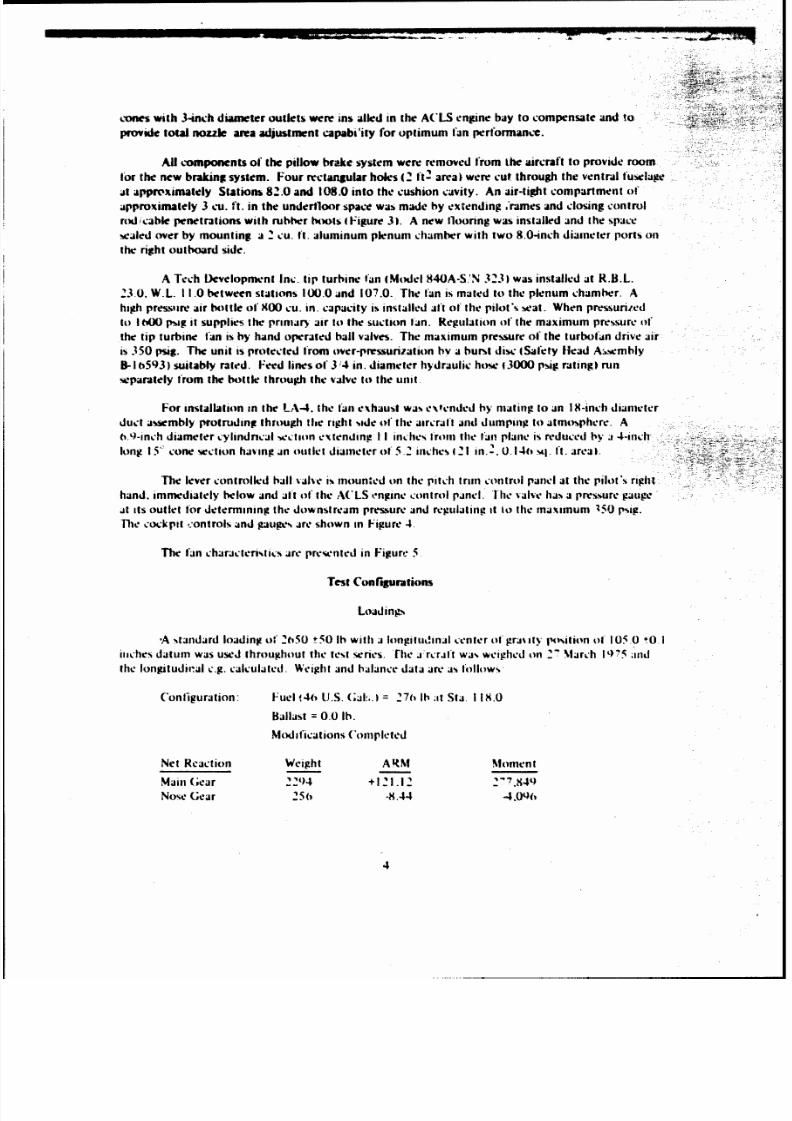
Figure 14. This
embodies
a wide. egg
shaped
planform for
improved roll stiffness,
as
compared
to
the
XC-8A
configuration,
and
was selected for
this
analysis because
it maximizes the base
area
for
suction.
The
basic
characteristics
of the
C-130 ACLS
are as
follows:
Airplane Gross Weight.
lb 155,000
Cushion
Area.
sq. ft.
589
Cushion
Pressure. psf 263
Trunk Pressure,
psi
488
Trunk Flow
at
I
-g.
cfs 1,400
Figures
15
and
16 illustrate the lubrication concept.
A
narrow swath
around the trunk ground
tangent contains a
hexagonal
pattern
of
jet
nozzles in the trunk with a solid
wear
plug in the center
of
each
of
the
hexagons.
These
plugs protect
the
trunk area
that has
the
most contact with the ground
from wear. This
area
at the
aft
end
of
the
trunk isgenerally in
contact
during
normal taxiing
due
to
the
location of
the airplane center of
gravity aft of the cushion center of pressure. The nozzles
around
the wear plugs
permit
lubrication
flow when the wear plugs
are
in
contact
with the surface.
They are
not closed off as
would be the
case
with nozzles in the
plugs themselves.
The
width
of this area
varies
from 6 inches at the forward end
of
the trunk
to 10
inches
at
the aft
end.
Outboard of the above
area.
there
are solid
wear
plugs but no jet nozzles. The wear plugs
extend a
distance of 18 inches
from
the ground
tangent to protect the
trunk from
wear
during land-
ing and
braking.
Inboard
is a
pattern of nozzle plugs for the
same radial distance. This nozzle
area primarily
provides the required cushion
flow to
maintain
cushion pressure.
However. when
suction
braking
is
applied and the nozzle
plugs come in
contact
with the surface, the
nozzles are closed off, reducing
the cushion flow and
thereby reducing the
suction
flow
that would otherwise be required.
A typical variation in
cushion
and footprint
widths
with
cushion pressure
and
ground
height
isshown
in
Figure 17 tor on
longitudinal
station.
The decrease in cushion
area
with
suction an d
stroke indicates
the
desirability
of awide
cushion
relative
to
the trunk cross-section size
to minimiie
the percentage
reduction in effective
suction
area
as suction isapplied.
To
determine
the
suction
requirements
for the
C-130
airplane,
the
results
from
the
LA-4
tests
were plotted as
the
ratio
of cushion pressure with
suction to
cushion pressure without
suction
versus
the ratio
of
suction flow to cushion
flow
as
shown in
Figure
18. Due
to
the
different lubrication
noz
zle
patterns
wherein
the
LA-4
nozzles
were
approximately
equally
distributed
inboard
and
outboard
of the ground
tangent but
the
C-130 has no nozzles
outboard,
it
was
assumed
that th LA4 trunk
flow
was equally divided between the cushion and to
the outside. Since the
data
points
were
clustered
within
a
small
area of Figure
18
due
to
the suction fan limits,
astraight line
variation was assumed
from the zero
suctinn point through
the data
points to
the point
representing a negative
suction
pres-
sure
equal
to th. no. real cushion pressure.
This suction
pressure
should provide ample
braking.
24
8/9/2019 Test of the Bell Aerospace LA-4 ACLS-ADA023850
http://slidepdf.com/reader/full/test-of-the-bell-aerospace-la-4-acls-ada023850 32/54
T
Figure
14.
C-
130
ACLS
(on
figurajtion
25

8/9/2019 Test of the Bell Aerospace LA-4 ACLS-ADA023850
http://slidepdf.com/reader/full/test-of-the-bell-aerospace-la-4-acls-ada023850 33/54
72-
.2.
:2 z
Z
00
26J

8/9/2019 Test of the Bell Aerospace LA-4 ACLS-ADA023850
http://slidepdf.com/reader/full/test-of-the-bell-aerospace-la-4-acls-ada023850 34/54
/0
/O
4
0O
0
Solid
~ Wear Plugs
Section A-A
Nozzle
Figure
16. (C-130 LubricatioI
Nozzle
D~etails
27

8/9/2019 Test of the Bell Aerospace LA-4 ACLS-ADA023850
http://slidepdf.com/reader/full/test-of-the-bell-aerospace-la-4-acls-ada023850 35/54
Z
En
00
(A
CLQ
-
0
0
-7.
0I-
d?
28

8/9/2019 Test of the Bell Aerospace LA-4 ACLS-ADA023850
http://slidepdf.com/reader/full/test-of-the-bell-aerospace-la-4-acls-ada023850 36/54
co
0
0'
0
0 0
6
oo
In-
o
Ci
(uoilns o0
o
-ins
82

8/9/2019 Test of the Bell Aerospace LA-4 ACLS-ADA023850
http://slidepdf.com/reader/full/test-of-the-bell-aerospace-la-4-acls-ada023850 37/54
To
determine
the cushion flow,
a level airplane
attitude was
assumed and equilibrium
condi-
tions
were calculated for
variations
in stroke.
That
is,
at
a given stroki
the cushion
pressure was
varied,
the resulting
footprint determined
and the
vertical forces summed.
From
cross plots
of stroke
and
cushion
pressure, at
a given trunk
pressure, the
equilibrium conditions
for
a specified
weight are
obtained.
This
is
illustrated
in
Figures
17, 19
and
20.
Figure
17
illustrates
the
determination
of
footprint
width.
This
was done for
several locations
around
the trunk
perimeter.
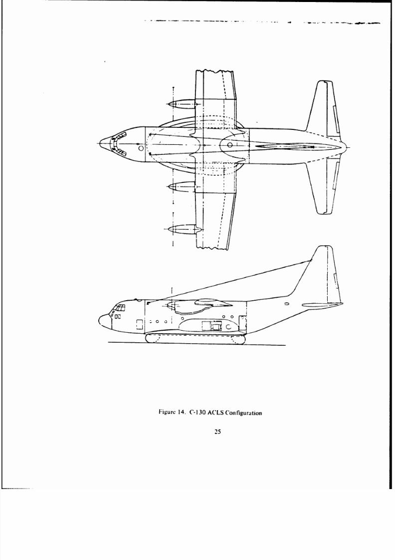
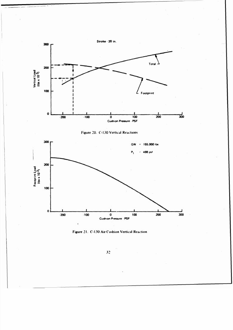
Figure
19 illustrates
a
typical
footprint.
It
is
for a
20-inch
stroke and trunk
and cushion
pressures
of
488 psf
and -144 psf
respectively.
The
vertical
forces
are as follows:
Ftotal
=
Pt XSfp
+ Pc x Sc
=
488
x 440 -
144 x 366.5
=
161,944
ib
Ffootprint
=
Pt x
Sfp
=
488
x440= 214,7201b
Plots
of
the
vertical
reactions
versus
cushion
pressure
at
fixed
stroke
are
made
as
shown
in
Figure 20.
Airplane
equilibrium
is the point
where
the
total
vertical
force is equal
to the
airplane
weight. Thus,
for example, at
a stroke
of
20 inches and
an
airplane
weight of 155.000 lb,
the cushion
pressure is -
157
psf
and moving
vertically to
the footprint
reaction, as
shown
by the dotted
lines, it
is seen
to
be
212,000
lb. Equilibrium
points
are determined
for the
range
of strokes and
plotted as
in
Figure
21,
which presents
footprint
load
versus cushion
pressure. The footprint
patterns
generated
above
determine the
extent of
nozzles
on
the
cushion
side of the trunk
that permit
flow
to
the
cushion.
To
be conservative
in estimates
of
fan
flow requirements,
the
tow
in the
center
"race
track"
area
of trunk
nozzles with solid
wear plugs was assumed to
vary
with the
square root of the pressure
difference
between
the trunk
and cushion
regardless
of the strokes:
the
nozzle plugs
in
contact
with
the
ground
completely
closed
off the
flow: and the
inboard
nozzle
plugs
not in contact
with
the
ground provided
flow as
a function of the trunk-to-cushion
pressure difference. The
resulting
cushion
flow
and
cushion
pressure
ratio
used
with the
LA-4
data
of
Figure
18
determines
the
suction
pressure
and
flow required.
The
calculations
of flow for
a
cushion
pressure of
+100 psf are as
follows:
Trunk
area
covered
with trunk
nozzles =
66.0 sq. ft.
Trunk
area
covered with nozzle
plugs = 115.5 sq. ft.
At Pc = 100 psf,
the equilibrium stroke
is
9 inches and the total
footprint
area is
175 sq.
ft.
The
nozzle
plug area in
contact
(and
closed
off) is 175-66
=
109
sq.
ft.
Thus the
nozzle plug trunk
area
passing flow
is
115.5 - 109 = 6.5 sq.
ft.
The
jet area is then:
0.034 x
66 + 0.023
x 6.5 =
2.394
sq.
ft.
where
0.034 and 0.023
are the
respective
porosities of
the
trunk
nozzle
area
and
the nozzle
plug
area.
Assuming
a discharge coefficient
of 0.6,
the following
is
the cashion
flow:
Q = 2.394
x 0.6 x
29 1488-100
= 820 cfs.
30

8/9/2019 Test of the Bell Aerospace LA-4 ACLS-ADA023850
http://slidepdf.com/reader/full/test-of-the-bell-aerospace-la-4-acls-ada023850 38/54
LL
U -
Ch~
7jS
wm
31 -
8/9/2019 Test of the Bell Aerospace LA-4 ACLS-ADA023850
http://slidepdf.com/reader/full/test-of-the-bell-aerospace-la-4-acls-ada023850 39/54
Stroke - 20 in.
100
Footprint
0
Cushion
Pressure -
PSF
Figure
20.
C-
130
Vertical
Reactions
300
GW
=155.00
bs
Pt
488
s
200
V
C -
IL
100
-200
*100
0
100
200
300
Cushion
Pressure
-PSF
Figure
2 1. C-
130 Air
Cushion
Verticail
Recation

8/9/2019 Test of the Bell Aerospace LA-4 ACLS-ADA023850
http://slidepdf.com/reader/full/test-of-the-bell-aerospace-la-4-acls-ada023850 40/54
Then
usinlg
the suction
faictor
fromn
Figure
18
at
a
Pc suction)/
Pc(no
suction)
=
10
0
18
h
siudion
re~quired is
Q1,tol-
820
ic
0.38
=
3 12
cis.
be
results are
jre.en tei
in Figure
22
as
suction
taln total
hecad
rise versus flow
rate.
rTie positive
region is
where
thle cushion prtessure is.
above
amblient
and
tile
negatike is hetow
ambient. Thle
normal
trunk flow
is
1400 :ts.
Abot e a hecad rise o1 0 the footprint width is sufficient
that Al
no/zle
plugs
are closed off.
Thle
maximumn suction air lip,
which
iscalculited
fronm
Q.IP 550, is approximately
(A 1compaied Awith
1800 for the baseline
air
cu
hion system.
To
determine
the brakitiig performance,
a tric-tion
coefficient
is
applied
to the vertical load of'
Figure 20. A :oetficie
n
of
0
8
yields
thie
f*ollow
ini ma 'amui decekraiotitlde to flhe
AC
LS
alone:
0.8 .
22.000
15
i.000
=14g-
I1w
aition
ot
9'
with
suction requiremlents
is
shown
inl F-igure 23 This
is.
of
course,
attenuated
bi
wing
lift which ha been
assumed
to be
/ero in til- analysis and
%ill
also h~e
ess onl those sorts of'
roug'h
suirfaces %4hich
do
not
e:Ic(i
l
lose Ott
thle
ict
110111Cand, inl
addition. permit
more
inflow
to
the
cush
ion
from
the
outside.
I owe~er. suLch
stilltaCes
ill proIduce
a igaher basic drag dute to
ir-
reetilairities
-: itactine the trunk.
Ithe effect
of
suction
hrak
ing
onl
C-1301 sfoppi
ng d
staie
;is :omplared
to
wheel
gear distanlce
X,
estimated
tor 155
.000) lb
%
iglit . I hie f fhl me .s1'nutiou
were
made:
('Lgrouild
roll
ttou~hdown
'faltlit
[toi Reterence I
tie
0heeld rO MId run is 3 1 t) feet.
From thle aiboe
issllill
lit
t'll
the st.itt
speett
Is calL1.1tett
to
lie
I '0 ft scc and thle touchdown
peed
1,
19~3.(It
sec. Celedtiul
file
timek
Itom
foilf iowni through rotation to no(le wheel c:ontact
and
brake
aplication,
and
:onsikleringk file entire ground i i
an
11Jerame
de
:eferaition fithe
C(tullt on :
j.ild
ierjmgc
de~eteraii,
of
l 3-
-
.- ,15
Itc
13

8/9/2019 Test of the Bell Aerospace LA-4 ACLS-ADA023850
http://slidepdf.com/reader/full/test-of-the-bell-aerospace-la-4-acls-ada023850 41/54
3:.-
___
Smooth
Surface
100-
-U.
n
C-
U
U.
200 400
600
800
1000
1200
1400
.0
Suction
Flow
Cn
-020
40
6
0
00
20
10
0
C
-~0
.-
1
GW
= 155,000 lbs
A
= 0.8
Smooth
Surface
Figure
23. C- 130 Braking
Performance
34

8/9/2019 Test of the Bell Aerospace LA-4 ACLS-ADA023850
http://slidepdf.com/reader/full/test-of-the-bell-aerospace-la-4-acls-ada023850 42/54
From F = ma, the average decelerating force
is:
155,000
32.2
x
5.95
=
28,641
32.2
The
footprint
load with suction, from Figure 2
1, is 233,000
lb
thus
the increase in retarding force
for an assumed friction coefficient
of
0.8
is:
F =
-(0.107
x
155,000) + 0.8 x
233,000
=
169,815
lb
where 0.
07
is the
attainble
friction coefficient for
the
wheeled C-130 at 155,000 lb
(From reference
2).
The stopping distance with suction braking
is
then:
28,544
3150
x
=
453
ft.
(169,815
+ 28,641)
Cushion suction for braking on the
C-130
can
be
accomplished by the use of tip turbine fans
as used on the LA-4 but
driven
by airplane
and
ACLS engine bleed or, more
simply,
by opening the
cushion to the ACLS
fan
inlet with controllable
doors
that can be modulated with the normal
inlet
doors to provide the required suction as illustrated schematically in Figure
24 .
In
such
an
arrangement,
the total head rise across the
fan
must
be
sufficient to provide normal
trunk pressure as
well
as suction; in this C-130 case 488 and 263 = 751 psf (neglecting losses).
In
the
wibraked
case,
eg., in
landing, fan operation will
then
be
far from stall, and
it is
probable
that
the
total system
can be operated
to
avoid fan
stall
even
in hard landings.
For
the C-130 airplane,
the
kinetic energy and
rate
ol t nergy dissipation in landing are
suf-
ficiently
high
that
pillow
brakes
will
be
marginal and
a
brakinj:
system with lower
contact
pressure
on the
landing surface will
be
desirable. Suction braking
can
provide this. The
use of
wear plugs as
described
for
the
C-130 trunk,
will
eliminate trunk wear
an,;
die
"race
track
of
solid
plugs surround-
ed
by trunk
nozzles will minimize
plug %ear.
It is
expected that
use of
suctior,
braking
would provide approximately neutral or slightly
negative directional
stability
during
braking
which may
be
controllable
with rudder, ailerons and
-control. Differential
braking
for
directional
control is
not
available.
It should
be remembered that
the airplane
yaw
attitude can divert
from
the
ground
track with the
ACLS
without signficiant con-
sequences.
Consideration has been
given to the:
weight
for
suction
braking equipment
on the
C-I
30.
Difinitive estimates
are
not
feasible without more
extension
system design.
However.
it appears
that
if
suction
braking
was designed
into the system
from
the
start
and
the cushion
fan
was
designed for the suction
case, the
incremental
weight compared with pillows would be
small.
35

8/9/2019 Test of the Bell Aerospace LA-4 ACLS-ADA023850
http://slidepdf.com/reader/full/test-of-the-bell-aerospace-la-4-acls-ada023850 43/54
>
0.
- C
o
L 2
36

8/9/2019 Test of the Bell Aerospace LA-4 ACLS-ADA023850
http://slidepdf.com/reader/full/test-of-the-bell-aerospace-la-4-acls-ada023850 44/54
Jindivik Suction
Bmking
For extrapolation to
the
Jindivik. the
configuration
of
Reference
3
was used. The
trunk flow
was assumed constant
at 1.4
lb/sec regardless
of
footprint
size
although the
referenced
report states
that it decreases as
would be expected with
a smooth
trunk
undersurface that would permit
the flow
to be
partially
closed
off
as
the
trunk
contacts the
surface. A
further discrepancy
in
flow occurs be-
cause
the
LA-4
data
of
Figure
18
is
based
on the
use
of
wear plugs
which
reduce
this
throttling
effect
and
this curve was applied to the Jindivik.
As
in
the
previous
extrapolations,
the trunk cross-sections were
calculated
and
the
equilibrium
footprint
load calculated for a
Rross
weight of
2470
lb.
Here a phenomenon
occurred
whici illustrates
the
disadvantage of a small
cushion
cavity and can cause a
arge discrepancy in calculated and
actual
braking data at high
suction
pressures
as
shown
subsequently. The discrepancy
is
that
in
the
tru....
geometry
calculations, no lateral friction
is
assumed
between the
trunk and
the
ground and as the
cushion pressure
is reduced, the
trunk
is free
to rotate
and
slide
in toward the center
of the vehicle.
The
effect
of this
is such
that,
because
of
the narrow cushion
width of
Jindivik, the suction area
is
too small to
provide
additional
suction effectiveness
beyond a cushion pressure of -100 psf.
In
actuality,
as suction
is
applied,
the
vehicle loses height
first and
the
degree
to which
the trunk reaches
the calculated equilibrium
depends on the distance the vehicle moves forward
after
the suction is
applied.
In the tests of Reference
3, this
distance
may
not
have
been
sufficient
for
final
equilibrium
to be reached.
The
calculated
footprint
load versus cushion
pressure is presented :n
Figure
25 d,
the
flat-
tening of the
curve at
-100
psf
is evident.
The curve
of Figure
1 was used to obtain the
suction requirements as presented in Figure
26.
From
the footprint load
versus
flow,
a
coefficient
of
friction of
0.8
produces
the braking
decelerations
of Figure 27
which
show a maximum
of
0.87.
The
tests of
Reference
3
were made
on
smooth
plywood which has
a fairly low coefficient
of friction. Therefore a friction
coefficient of 0.35 was
assumed
'or
a
comparison
of
calculations
with
Figure
19
of
Reference
3
as
shown
in
Figure
28.
Correlation
is
-od
at
low suction
and
the
figure
illustrates the
divergence
at
high suction
pressures.
Duz to
the differences in flow
conditions
previouly discussed.
Zhere is no
correlation with
Figure
30 of
Reference
3.
The stopping distance was calculated
for
a touchdown speed
of
130
knots, zero lift
and
thrust
during braking,
and
a suction cushion pressure
of
-100
psf
with
a friction coefficient of
0.8.
v
2
S=
2a
S
130x
1.69)
= 861
ft.
2
0.87
x
32.2
Reference 4 indicated
the
desirability
of
having greater
triction
aft
of the e.g., than forward
to improve
the
directional
stability
during braking. Although the air
cushion system
design
was dif-
37

8/9/2019 Test of the Bell Aerospace LA-4 ACLS-ADA023850
http://slidepdf.com/reader/full/test-of-the-bell-aerospace-la-4-acls-ada023850 45/54
Footprint
Load
(lbs)
%
2470
1lbs
2000
.200
-100
0
100
200
Cushion
Prassure fpst)
Figure 25.
Jindivik
Vertical
Load
200
100
GW
=2470
lbs
cc
0 1020
30
Suction
Flow
o0
CFS)
.100
A20
Figure
2().
Jindivik
Suction
Requirements
38

8/9/2019 Test of the Bell Aerospace LA-4 ACLS-ADA023850
http://slidepdf.com/reader/full/test-of-the-bell-aerospace-la-4-acls-ada023850 46/54
Suction
Flaw
CFS)
0
10
20
30
0
.2
Fiue2,JndvkBaig
efrac
.39

8/9/2019 Test of the Bell Aerospace LA-4 ACLS-ADA023850
http://slidepdf.com/reader/full/test-of-the-bell-aerospace-la-4-acls-ada023850 47/54
+1.0
*.
AFFDL-TR-74-64
+0.5
---
Extrapolated
LA-4
0
C
.0
-
0.5
0
0
500
1000
1500
2000
Braking
Force Ibs)
Figure
28.
.Jindivik
Suction
Braking Comparison
40

8/9/2019 Test of the Bell Aerospace LA-4 ACLS-ADA023850
http://slidepdf.com/reader/full/test-of-the-bell-aerospace-la-4-acls-ada023850 48/54
terent
than
that of Reference
3, the general conclusions
should
apply. Reference
4
does not
indicate
the
effect of
longitudir,al
cg-cp
relation but
it is assumed
they are similar
to Reference
3.
Thus
it
is
expected
that landing
ground
runs can be
kept within 50
feet of
the landing
area centerline
but
if
the friction coefficient
is greater
than
0.5,
large
yaw excursions
are
possible.
Reference
6
indicated that a suction braking system for RPVs
using an ejector and stored gas
can
be
designed
for short
brake
durations for about 10 lb.
XC-8A Suction
Braking
A suction
braking system for the
XC-8A airplane with its present
ACLS system requires
careful consideration because of the potential for
stalling
the
ASP-10 fans and the
resulting
stall
characteristics
and
the fact that the
system presently provides considerable excess airflow.
The
system controls
and
logic should be
changed so
that the
trim ports
remain closed to
reduce suction
requirements
to
reasonable levels, and the flow diverter vanes
modulated to
by-pass
flow during
suction braking to prevent
fan stall. Consideration should be given to operating with only
the
ASP-10 to reduce the
suction flow requirement and thrust due to
diverted
flow.
During braking,
the
vane modulation can
be such as to permit the trank pressure to
increase beyond its normal
value
to
reduce
the
heave
dipping tendency when
suction is applied. However, in
the following
analysis,
trunk
pressure is
assumed constant.
Using
the
above technique, the
same
approach
to
nozzle
plug and trunk nozzle distribution
as outlined tor the
C-130
is used with trunk
No. 3
which
is also provided with pillow
brakes.
No
changes to
the trunk
are
assumed other than the distribution
of
wear
plugs in the existing hole
pattern
as shown
in
Bell
drawing 7396-185084.
The
wear plug distribution is as
follows.
The racetrack around the ground tangent
is selected
to
be
6
inches wide ahead of the
brake
pads, 8
inches wide between the brake pads and
10 inches
wide aft of
the
pads.
All but
the aft
end
have
nozzle plugs in every other jet hole
and
the
aft section has
a
solid plug
pattern
such that
each
plug
is surrounded by
six
jet
holes. Nozzle plugs are used in the
above
areas as
opposed to
solid
plugs as
for
the
C 1
30
to permit
adequate
flow in
the
non-braking
condition
to prevent fan stall
without
vane modulation. Inside the
above
racetrack,
all
holes contain nozzle plugs.
Following the same analysis as for
the C-130
in calculating
the footprint
equilibrium
conditions for different suction pressures, the footprint load is as shown
in Figure
29 for a gross
weight of
41.000 lb and the corresponding suction
requirements are
as
shown in Figure
30.
The
deceleration capability due to suction
braking
only and assuming
zero wing lift is
shown in
Figure
31.
and shows a maximum
of
1.04 g's for a
cushion pressure
of -170
psi and a
weight
of 41.000 lb,
and
a friction coefficient
of
0.8. Again,
this will
vary with
landing surface smoothness and
friction
coefficient.
For
a
landing distance comparison,
the
following data were used
from
Reference 5:
Touchdown
speed
= 70
knots
Ground
run = 640
ft.
from which
the
average deceleration is
3.828
ft/sec
2
and the average decelerating force is
4874 lb.
41

8/9/2019 Test of the Bell Aerospace LA-4 ACLS-ADA023850
http://slidepdf.com/reader/full/test-of-the-bell-aerospace-la-4-acls-ada023850 49/54
Footprint
Load
(lb
x103
GN
41,000
lbs
20
I
-200
-100 0
100
200
Cushion Pressure -
pst
Figure 29.
XC-8A Footprint
Load
42

8/9/2019 Test of the Bell Aerospace LA-4 ACLS-ADA023850
http://slidepdf.com/reader/full/test-of-the-bell-aerospace-la-4-acls-ada023850 50/54
200
Suction Fan
Total
Head
100
Rise
IPSF)
0
100 200
30 0
Sucticn Flow
(cfs)
-100
*2M
Figure
30.
XC-8A
Suction Requirements
Suction
Flow (cfs)
0
100 200
300
0
g-S
1.0
Figure
3 1.
XC-8A Braking Performance
43

8/9/2019 Test of the Bell Aerospace LA-4 ACLS-ADA023850
http://slidepdf.com/reader/full/test-of-the-bell-aerospace-la-4-acls-ada023850 51/54
The
footprint load with
maximum
suction is,
from Figure 29,
53,500 lb.
Ass:ming zero lift
during braking, the coefficient
of friction of
0.25
from Reference
4
wheel braking.
the
increase
in re-
tarding force
due
to
suction
is:
F
=
0.8 x 53.500-0.25 x 41,000=32.55Olb
assuming a
friction coefficient
of
0.8
for
ACLS
braking.
The stopping
distance with
suction providing
a cushion
pressure
of
-170 psf is:
4874
640x
=
83ft.
4874 + 32,550
The application
of
suction
braking
to the
XC-8A
airplane
will require
some means of
applying
suction. With the present
design,
the use
of
the
ASP-10 fans is impractical. Auxiliary tip
driven fPip,
,tlild e
used such
as the Tech, Development Model 875 of
which
three are required to
provide adequate flow
for
a negative cushion pressure of 170 psf. However, they would require a
drive
flow of about 7.5
lb/sec
which
is more
than that available from the airplane engines, even at
maximum power,
and a storage tank would be required. The direct bleed
available
from two
T-64
engines
at
maximum
reverse
thrust
used
with
two
model
875
fans
would
be
adequate to produce
a
cushion pressure of about -50 psf and
a
corresponding deceleration due to suction of about 0.75
g's.
The
weight
penalty for three fans
and
adequate storage gas for
20
seconds of braking is
estimated to be as follows:
Weight
lb)
2 -
24.5
in the
3000
psi tanks 22 0
3
- model
875 fans 75
1 -
pressure regulator 80
Installation,
plumbing
and
controls 45
Total 320 lb
It is assumed the pillow brakes would remain unchanged.
The
directional stability during
braking based on the assumption of zgro pitch attitude
would
be slightly destabilizing to the XC-8A.
However.
with the e.g. aft of the cushion c.p. as
is
the
case, this destabilization would be
somewhat
nullified by the
greater
drag at
the
aft end of the
trunk.
The
use
of
suction
braking would not induce trunk wear since sacrificial wear plugs
are
used.
There
are no
weight
penalties
to
the trunk
itself:
however,
larger wear plhgs may be necessary
for acceptable replacement frequency.
44

8/9/2019 Test of the Bell Aerospace LA-4 ACLS-ADA023850
http://slidepdf.com/reader/full/test-of-the-bell-aerospace-la-4-acls-ada023850 52/54
CONCLUSIONS AND) RECOMMEND ATIONS
1.
The rmu'whi of
the tei.t program
%upport
the
theory
that %.em'
tfctne
brakinp
is
achiceabhk
h%
iuetion
suh%tant
ial
iicgat
i%
preiiure
j
reaied
in
thle
Cti iin
aw.tv
fow
a
.wtlon
flow
mucjth
IevA
thani
cushion
flow
. The miimni
decekeratioi chiiied
Aj
0I~ Ultimate
levek ad~licejhhk
were
not reali/ed
in the
test
heeatiw of deficiericie%
n the tconfiguration -failtire to
retia
oille
plum
and a
non-optimun
plug
configuration.
3. Baiekd on
the
flo%
required
for mi
lion
generation
and applinp known
air Iubricition
andt
friction parinicterm
a
deceleraiion
p'otentil
of' 1.4 gct-in he predicd lur
a
CA SO. (0
X for iindii :
and 1.04
for in
\(SA
deiiened for
tofl
hrak
nec
A( LS
in a
reaili-ti
tonfieturation.
I his
i
n the
order of tM
i to three ti, hi
t
%lhcti
%:an e produced with hed
hn~kt-
4.
Repeat tte t ire recuuiimended
lo c-.talh%h that
the de~clhted
thtoni
:an
he
pru'wei In
ti.
repeat teiti. the
optinimn
plut
evoinctr%
shotild
firm
t
he
pecitied
and .uitable
retention
%hould
he
citahlished. Brake %kid% hh'uld he
eliminited in fajor
of in mierall uniforni plug di~trihuttioii
Ad-
ditional ictiofl (a ..eomd
identemal
fani htildie pirmiideil
and tjn control inimroeld [-till detelcra-
tion potential iliould thent he
realie
5. Stwtion
brain
i
bjl
applied ito A(
I-S
tem-%
t %cefht ine
~er pillcm
hnakes
45

8/9/2019 Test of the Bell Aerospace LA-4 ACLS-ADA023850
http://slidepdf.com/reader/full/test-of-the-bell-aerospace-la-4-acls-ada023850 53/54
REFERENCES
I.
C-130E
Hercules Operational Planning
Data Book. AER300B.
I
December
964.
Lockheed
Georgia
Company.
2.
C-I30E Aerodynamic Data.
ER7357. Lockheed Georgia Company.
3.
Laboratory
Tests of an
Air Cushion Recovery System for
the Jindivik Aircraft.
AFFI)L-FR-
74-64.
April
1974.
4.
Design
of
an
Air Cushion Recovery System
for
the iindi~ik
Drone Aircraft. AFFDL-TR-74-
38
March 1974.
5. DHC-5
Per'urmance
-
Volume
I I
- Landing. AEROC
5.2.G. 1.
Delfavilland Aircraft
of('anada.
October l93.
6. A Study of Air ('ushon
Landing Systems for Recovery of
Unmanned
Aircraft.
AFFDL-'TR-
72-87. July 1972.
46

8/9/2019 Test of the Bell Aerospace LA-4 ACLS-ADA023850
http://slidepdf.com/reader/full/test-of-the-bell-aerospace-la-4-acls-ada023850 54/54
LIST
OF
SYMBOLS
a acceleration
(ft sec
2
)
CL
lift
coefficient
iLiq
S)
F
= Iore I Ibs)
g aceleration
(Jimensionlks
*'g's- normalized
by acceleration of gravity,
32,174
1 t
,
e.
L
. =
aerodynami,'
lift i l
P pes, tir Ipst)
q dynamic pressure
(psi)
Q
flow rate fl s)
=
di tjncc Ift)
S
.area.
ft
V
=
speed (
ft
se%
u = co
cticent
of Irition
Subscript-;
=
cushion
fp =
footprint
t = trunk
*
-'' -I