test facilities and component developments sami tantawi slac may 15, 2008
TRANSCRIPT
Test Facilities and Component Developments
Sami TantawiSLAC
May 15, 2008

High Gradient Research Facilities at SLACWe concentrated on being accessible to the rest of the collaboration through Improving
our test facilities • 2-pack
– new modulator have been installed and the system will be under vacuum and run for the first time in 5 years in the spring of 2008
• ASTA – powered by two 50 MW Klystrons whose 1.5 us pulses are combined and compressed using SLED-
II expected to produce up to ~ 500 MW – Cost effective testing through reusable couplers and supply compatible flanges. Hence, other groups
need only to worry about the design of the accelerator structure “proper”– We are introducing new types of gate valve to minimize, time, effort and cost for installation of
different experiments – a very versatile pulse length and output power – ASTA was put back together and started its initial commissioning in Jan 2008.
• individual stations: – Two Individual Stations, each have 1 50 MW klystron with 1.5 us pulse width. – very productive, more than 12 experiments have been conducted in these stations in 2007
• NLCTA – Station 1 and 2 each are powered by two 50 MW Klystrons whose 1.5 us pulses are combined and
compressed using SLED-II and Have two, 2.5 m slots for structures. It Can run 24/7 using automatic controls
– Six week run of CERN HDX11-Mo quadrant structure - gradient at a 10-6 breakdown rate with 70 ns pulses only 60 MV/m.
– Run slotted, a/ = 0.18, 75 cm NLC structure (H75vg4S18) with 150 ns pulses - at 102 MV/m, breakdown rate = 6 10-6.
– Run early NLC, non-slotted, 53 cm, smaller aperture (a/ = 0.13) structure (T53vg3MC) at short pulses - gradient at a 10-6 breakdown rate with 100 ns pulses is 105 MV/m. Have ran about 2200 hours since structure installed in 4/07

Pulse compressors at ASTA and Two-Pack
• All New overmoded components for high reliability (So that we are testing structure rather than RF system)
• Flexible pulse length and gain
• High efficiency
• Each is powered by two klystrons
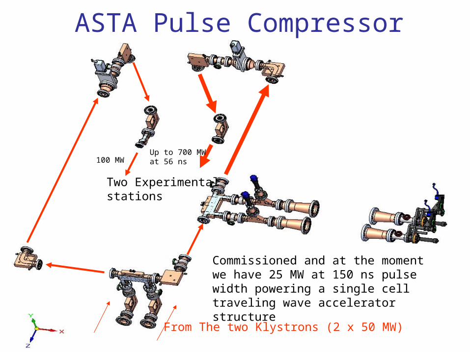
ASTA Pulse Compressor
From The two Klystrons (2 x 50 MW)
Two Experimental stations
Up to 700 MW at 56 ns100 MW
Commissioned and at the moment we have 25 MW at 150 ns pulse width powering a single cell traveling wave accelerator structure
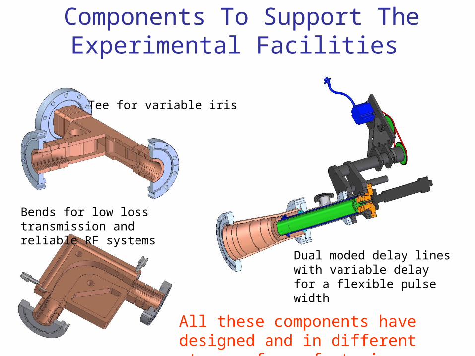
Components To Support The Experimental Facilities
Tee for variable iris
Bends for low loss transmission and reliable RF systems
Dual moded delay lines with variable delay for a flexible pulse width
All these components have designed and in different stages of manufacturing
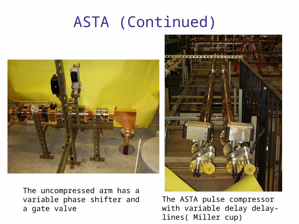
ASTA (Continued)
The uncompressed arm has a variable phase shifter and a gate valve The ASTA pulse compressor with
variable delay delay-lines( Miller cup)
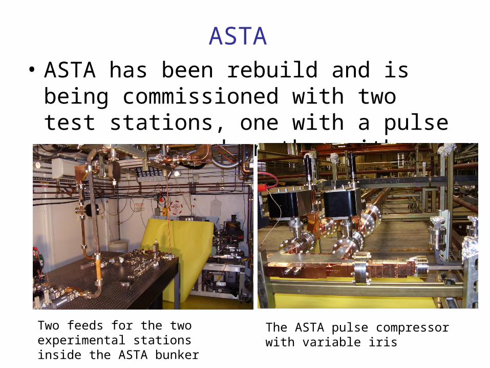
ASTA • ASTA has been rebuild and is being
commissioned with two test stations, one with a pulse compressor and another with out.
Two feeds for the two experimental stations inside the ASTA bunker
The ASTA pulse compressor with variable iris

Gate Valve
We have designed a new type of gate valves to allow fast exchange of experimental structure. This will cut the change time from a week to one day (so far it has been tested to 300 ns at 100 MW) A. Grudiev, “Development Of A Novel Rf Waveguide Vacuum Valve,” Proceedings of EPAC 2006, Edinburgh, Scotland


0 1 2 3 4 5 6 7 8 9 10 110
20
40
60
80
100
120
turns
S21
Pha
se (
degr
ees)
Circular TE01 Mode Slide Phase Shifter
simulation
design
11.3 11.35 11.4 11.45 11.5 11.55-45
-40
-35
-30
-25
-20
-15
-10
-5
0
frequency (GHz)
S11
Am
plitu
de (
dB)
11.3 11.35 11.4 11.45 11.5 11.55-1
-0.9
-0.8
-0.7
-0.6
-0.5
-0.4
-0.3
-0.2
-0.1
0
frequency (GHz)
S21
Am
plitu
de (
dB)
10.82°/turn
~112° range
cold test results
@ 11.424 GHz, |S11| = -41 dB to -27 dB
~3% loss mostly from mode launchers
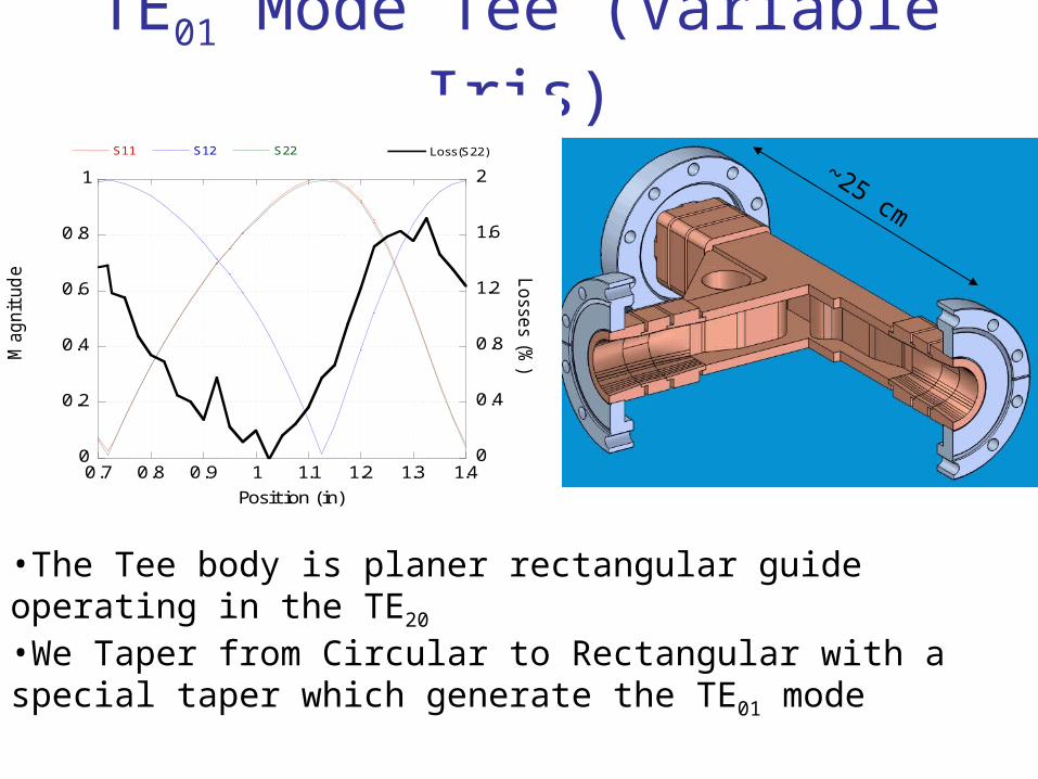
TE01 Mode Tee (Variable Iris)
0
0.2
0.4
0.6
0.8
1
0
0.4
0.8
1.2
1.6
2
0.7 0.8 0.9 1 1.1 1.2 1.3 1.4
S11 S12 S22 Loss(S22)
Magnit
ude L
osse
s (%)
Position (in)
~25 cm
•The Tee body is planer rectangular guide operating in the TE20
•We Taper from Circular to Rectangular with a special taper which generate the TE01 mode
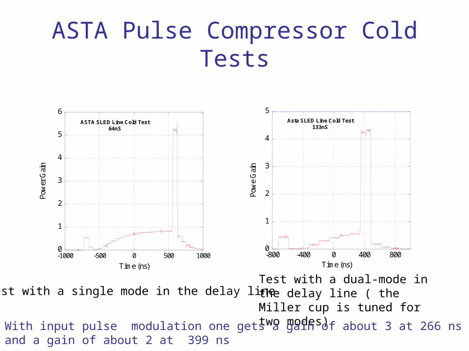
ASTA Pulse Compressor Cold Tests
0
1
2
3
4
5
6
-1000 -500 0 500 1000
ASTA SLED Line Cold Test64nS
Pow
er G
ain
Time (ns)
0
1
2
3
4
5
-800 -400 0 400 800
Asta SLED Line Cold Test133nS
Pow
e G
ain
Time (ns)
Test with a single mode in the delay lineTest with a dual-mode in the delay line ( the Miller cup is tuned for two modes)
With input pulse modulation one gets a gain of about 3 at 266 ns and a gain of about 2 at 399 ns

Low-Level RF and Data Acquisition
Satellite Receiver LNB
Custom Board with Power Detector and Coherent Power and Phase Detectors
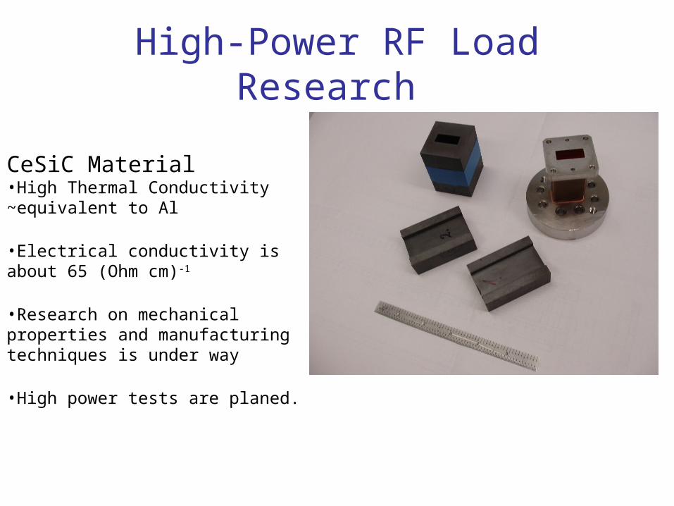
High-Power RF Load Research
CeSiC Material •High Thermal Conductivity ~equivalent to Al
•Electrical conductivity is about 65 (Ohm cm)-1
•Research on mechanical properties and manufacturing techniques is under way
•High power tests are planed.