test equipment solutions datasheet equipment solutions datasheet ... worldwide network of local...
TRANSCRIPT

Test Equipment Solutions Datasheet
Test Equipment Solutions Ltd specialise in the second user sale, rental and distribution of quality test & measurement (T&M) equipment. We stock all major equipment types such as spectrum analyzers, signal generators, oscilloscopes, power meters, logic analysers etc from all the major suppliers such as Agilent, Tektronix, Anritsu and Rohde & Schwarz.
We are focused at the professional end of the marketplace, primarily working with customers for whom high performance, quality and service are key, whilst realising the cost savings that second user equipment offers. As such, we fully test & refurbish equipment in our in-house, traceable Lab. Items are supplied with manuals, accessories and typically a full no-quibble 2 year warranty. Our staff have extensive backgrounds in T&M, totalling over 150 years of combined experience, which enables us to deliver industry-leading service and support. We endeavour to be customer focused in every way right down to the detail, such as offering free delivery on sales, covering the cost of warranty returns BOTH ways (plus supplying a loan unit, if available) and supplying a free business tool with every order.
As well as the headline benefit of cost saving, second user offers shorter lead times, higher reliability and multivendor solutions. Rental, of course, is ideal for shorter term needs and offers fast delivery, flexibility, try-before-you-buy, zero capital expenditure, lower risk and off balance sheet accounting. Both second user and rental improve the key business measure of Return On Capital Employed.
We are based near Heathrow Airport in the UK from where we supply test equipment worldwide. Our facility incorporates Sales, Support, Admin, Logistics and our own in-house Lab.
All products supplied by Test Equipment Solutions include:
- No-quibble parts & labour warranty (we provide transport for UK mainland addresses).- Free loan equipment during warranty repair, if available.- Full electrical, mechanical and safety refurbishment in our in-house Lab.- Certificate of Conformance (calibration available on request).- Manuals and accessories required for normal operation.- Free insured delivery to your UK mainland address (sales).- Support from our team of seasoned Test & Measurement engineers.- ISO9001 quality assurance.
Test equipment Solutions LtdUnit 8 Elder WayWaterside DriveLangleyBerkshireSL3 6EP
T: +44 (0)1753 596000F: +44 (0)1753 596001
Email: [email protected]: www.TestEquipmentHQ.com
Te
st &
Mea
sure
men
t
Prod
uct B
roch
ure
| 04.
00R&S®CMW500 Wideband Radio Communication TesterRF production testing
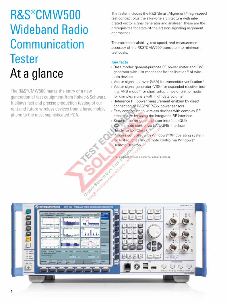
The tester includes the R&S®Smart Alignment 1) high-speed test concept plus the all-in-one architecture with inte-grated vector signal generator and analyzer . These are the prerequisites for state-of-the-art non-signaling alignment approaches.
The extreme scalability, test speed, and measurement accuracy of the R&S®CMW500 translate into minimum test costs.
Key factsBase model: general-purpose RF power meter and CW J
generator with List modes for fast calibration 1) of wire-less devicesVector signal analyzer (VSA) for transmitter verification J 1)
Vector signal generator (VSG) for expanded receiver test- J
ing: ARB mode 1) for short setup times or online mode 1) for complex signals with high data volumeReference RF power measurement enabled by direct J
connection of R&S®NRP-Zxx power sensorsEasy connection to wireless devices with complex RF J
architecture by using the integrated RF interfaceState-of-the-art graphical user interface (GUI) J
SCPI remote control via LAN/GPIB interface J
Ready for LXI Class C J
Process controller with Windows® XP operating system J
for test routines and remote control via Windows® Remote Desktop
The R&S®CMW500 marks the entry of a new generation of test equipment from Rohde & Schwarz. It allows fast and precise production testing of cur-rent and future wireless devices from a basic mobile phone to the most sophisticated PDA.
R&S®CMW500 Wideband Radio Communication TesterAt a glance
1) For explanations see glossary at end of brochure.
2
R&S®CMW500 Wideband Radio Communication TesterBenefits and key features
Multitechnology solutionCellular technologies: GSM/GPRS/EDGE, WCDMA /HSPA/HSPA+, LTE FDD, LTE TDD (TD-LTE), Mobile WiMAX™/CDMA2000® 1xRTT, CDMA2000® 1xEV-DO, TD-SCDMA Noncellular and supplementary technologies: GPS, DVB, Bluetooth®, WLAN
page 4 ▷
Future-ready RF parameters3.3/6 GHz frequency range and 40/70 MHz analyzer/ generator IF bandwidth
page 5 ▷
Drastically reduced test costs; alignment up to ten times fasterInnovative Rohde & Schwarz test concepts: R&S®Smart Alignment 1) and R&S®Multi-Evaluation List mode 1)
page 6 ▷
Designed for high first pass yieldHigh absolute accuracy plus repeatability and linearity
page 7 ▷
Optimized handling for production test systems All-in-one architecture 1) with fully automatic RF path correction 1) and Press & Go 1) applications
page 8 ▷
Minimum floor spaceDual-tester configuration enables simultaneous testing of two identical wireless devices
page 10 ▷
Reduced operating costs due to 24-month calibration intervalOptimized solution for every application: selectable calibration interval of 12 or 24 months for high absolute accuracy or reduced costs
page 12 ▷
From pre-sale to service. At your doorstep.Worldwide network of local Rohde & Schwarz experts in over 70 countries
page 13 ▷
“WiMAX Forum“ is a registered trademark of the WiMAX Forum. “WiMAX,“ the WiMAX Forum logo, “WiMAX Forum Certified,“ and the WiMAX Forum Certified logo are trademarks of the WiMAX Forum.CDMA2000® is a registered trademark of the Telecommunications Industry Association (TIA -USA).The Bluetooth® word mark and logos are registered trademarks owned by Bluetooth SIG, Inc. and any use of such marks by Rohde & Schwarz is under license.
Rohde & Schwarz R&S®CMW500 Wideband Radio Communication Tester 3
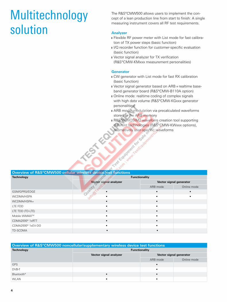
The R&S®CMW500 allows users to implement the con-cept of a lean production line from start to finish: A single measuring instrument covers all RF test requirements.
AnalyzerFlexible RF power meter with List mode for fast calibra- J
tion of TX power steps (basic function)I/Q recorder function for customer-specific evaluation J
(basic function)Vector signal analyzer for TX verification J
(R&S®CMW-KMxxx measurement personalities)
GeneratorCW generator with List mode for fast RX calibration J
( basic function)Vector signal generator based on ARB + realtime base- J
band generator board (R&S®CMW-B110A option)Online mode: realtime coding of complex signals J
with high data volume (R&S®CMW-KGxxx generator personalities)ARB mode: modulation via precalculated waveforms J
stored in the ARB memory R&S®WinIQSIM2 waveform creation tool supporting J
different technologies (R&S®CMW-KWxxx options), alternatively user-specific waveforms
Multitechnology solution
Overview of R&S®CMW500 noncellular/supplementary wireless device test functionsTechnology Functionality
Vector signal analyzer Vector signal generator
ARB mode Online mode
GPS •
DVB-T •
Bluetooth® • •
WLAN • •
Overview of R&S®CMW500 cellular wireless device test functionsTechnology Functionality
Vector signal analyzer Vector signal generator
ARB mode Online mode
GSM/GPRS/EDGE • • •
WCDMA/HSPA • • •
WCDMA/HSPA+ • •
LTE FDD • •
LTE TDD (TD-LTE) • •
Mobile WiMAXTM • •
CDMA2000® 1xRTT • •
CDMA2000® 1xEV-DO • •
TD-SCDMA • •
4

Comprehensive RF front end
eliminates external hardware
(dual-tester front panel).
Future-ready RF parameters
Minimum risk due to scalable 3.3 GHz or 6 GHz frequency rangeThe frequency range of the base model is 70 MHz to 3.3 GHz. Extension to 6 GHz by means of software up-date (R&S®CMW-KB036 option) and instrument calibra-tion. Quick and easy adaptation to new technologies and bands.
High measurement speed owing to 40 MHz IF bandwidthSimple one-sweep broadband measurements can be performed. Technologies such as LTE/EUTRA with trans-mission bandwidths of up to 20 MHz can be handled.
Simplified test system architecture through wide RF level range
Output level range from –130 dBm to +8 dBm J
(CW, RMS)Output level dynamic range of 128 dB J
Input level range from –84 dBm to +34 dBm J
(power meter, CW, RMS)
The wide dynamic range makes additional external amplifiers or attenuators unnecessary. You can reduce test system costs without having to accept restrictions on reliability or accuracy.
Rohde & Schwarz R&S®CMW500 Wideband Radio Communication Tester 5
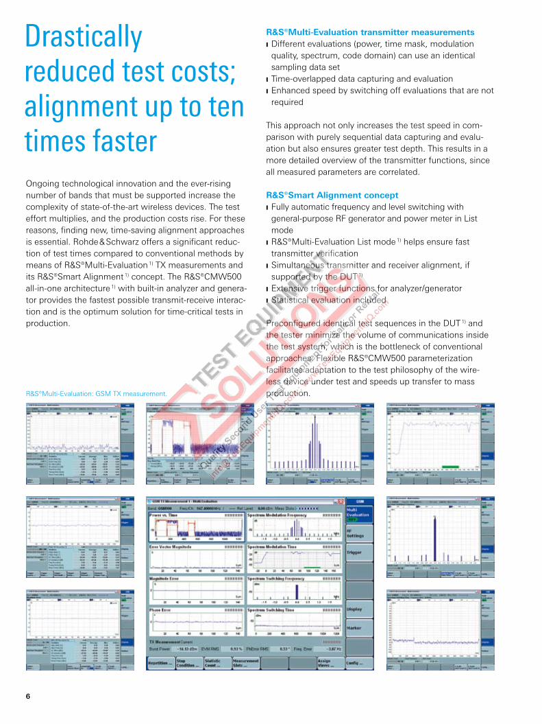
R&S®Multi-Evaluation: GSM TX measurement.
Drastically reduced test costs; alignment up to ten times faster
R&S®Multi-Evaluation transmitter measurementsDifferent evaluations (power, time mask, modulation J
quality , spectrum, code domain) can use an identical sampling data setTime-overlapped data capturing and evaluation J
Enhanced speed by switching off evaluations that are not J
required
This approach not only increases the test speed in com-parison with purely sequential data capturing and evalu-ation but also ensures greater test depth. This results in a more detailed overview of the transmitter functions, since all measured parameters are correlated.
R&S®Smart Alignment conceptFully automatic frequency and level switching with J
general-purpose RF generator and power meter in List modeR&S®Multi-Evaluation List mode J 1) helps ensure fast transmitter verificationSimultaneous transmitter and receiver alignment, if J
supported by the DUT 1)
Extensive trigger functions for analyzer/generator J
Statistical evaluation included J
Preconfigured identical test sequences in the DUT 1) and the tester minimize the volume of communications inside the test system, which is the bottleneck of conventional approaches. Flexible R&S®CMW500 parameterization facilitates adaptation to the test philosophy of the wire-less device under test and speeds up transfer to mass production.
Ongoing technological innovation and the ever-rising number of bands that must be supported increase the complexity of state-of-the-art wireless devices. The test effort multiplies, and the production costs rise. For these reasons, finding new, time-saving alignment approaches is essential. Rohde & Schwarz offers a significant reduc-tion of test times compared to conventional methods by means of R&S®Multi-Evaluation 1) TX measurements and its R&S®Smart Alignment 1) concept. The R&S®CMW500 all-in-one architecture 1) with built-in analyzer and genera-tor provides the fastest possible transmit-receive interac-tion and is the optimum solution for time-critical tests in production.
6
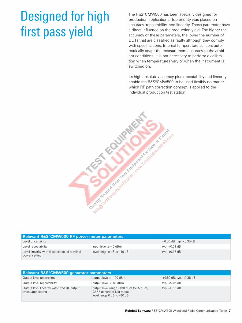
Designed for high first pass yield
The R&S®CMW500 has been specially designed for production applications: Top priority was placed on accuracy, repeatability, and linearity. These parameter have a direct influence on the production yield. The higher the accuracy of these parameters, the lower the number of DUTs that are classified as faulty although they comply with specifications. Internal temperature sensors auto-matically adapt the measurement accuracy to the ambi-ent conditions. It is not necessary to perform a calibra-tion when temperatures vary or when the instrument is switched on.
Its high absolute accuracy plus repeatability and linearity enable the R&S®CMW500 to be used flexibly no matter which RF path correction concept is applied to the individual production test station.
Relevant R&S®CMW500 RF power meter parametersLevel uncertainty <0.50 dB, typ. <0.30 dB
Level repeatability input level ≥–40 dBm typ. <0.01 dB
Level linearity with fixed expected nominal power setting
level range 0 dB to –40 dB typ. <0.15 dB
Relevant R&S®CMW500 generator parametersOutput level uncertainty output level >–120 dBm <0.60 dB, typ. <0.36 dB
Output level repeatability output level <–80 dBm typ. <0.05 dB
Output level linearity with fixed RF output attenuator setting
output level range –130 dBm to –5 dBm,GPRF generator List mode, level range 0 dB to –30 dB
typ. <0.15 dB
Rohde & Schwarz R&S®CMW500 Wideband Radio Communication Tester 7

Block diagram of the R&S®CMW500
R&S®CMW500 wideband radio communication tester
RF frontend
DUT
MMI
TriggeringRF1 COM
RF2 COM
RF1 OUTVSG
VSA
Peripherals
Controller
Timingreference
Remotecontrol
LAN/IEEE
Powersupply
RX3
RX1
TX1
RX2
TX2
Optimized handling for production test systems
The R&S®CMW500 is a turnkey solution that can start test-ing immediately after delivery. The fully integrated tester with calibrated RF paths and Press & Go 1) applications sim-plifies generating and updating test sequences and pro-duction test systems. The all-in-one architecture 1) ensures maximum test performance plus minimum footprint and optimum power consumption. This concept for minimiz-ing test costs comes from a company that has been suc-cessfully supplying solutions for the production of wireless devices for more than 30 years: Rohde & Schwarz.
Minimum user risk owing to all-in-one architecture Built-in vector signal analyzer and generator J
SCPI remote control via LAN or GPIB interface J
Windows® XP operating system J
Remote control via Windows® Remote Desktop J
Connectors for mouse, keyboard, and external monitor J
Internal TCXO or OCXO timebase and 10 MHz reference J
frequency outputExternal reference frequency (alternative) J
Fully automatic RF path correction concept J 1) of frequency, temperature, and level in realtime Completely calibrated solution J
Completely standard-conforming EMC J 1) characteristicsMatched power supply J
The turnkey solution provides assured measurement accuracy without the user’s constant attention. Time- and cost-intensive repetitive self-alignment procedures can be omitted.
8
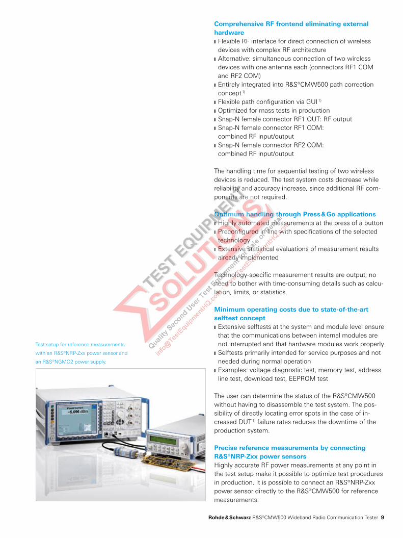
Test setup for reference measurements
with an R&S®NRP-Zxx power sensor and
an R&S®NGMO2 power supply.
Comprehensive RF frontend eliminating external hardware
Flexible RF interface for direct connection of wireless J
devices with complex RF architecture Alternative: simultaneous connection of two wireless J
devices with one antenna each (connectors RF1 COM and RF2 COM)Entirely integrated into R&S®CMW500 path correction J
concept 1)
Flexible path configuration via GUI J 1)
Optimized for mass tests in production J
Snap-N female connector RF1 OUT: RF output J
Snap-N female connector RF1 COM: J
combined RF input/outputSnap-N female connector RF2 COM: J
combined RF input/output
The handling time for sequential testing of two wireless devices is reduced. The test system costs decrease while reliability and accuracy increase, since additional RF com-ponents are not required.
Optimum handling through Press & Go applicationsHighly automated measurements at the press of a button J
Preconfigured in line with specifications of the selected J
technologyExtensive statistical evaluations of measurement results J
already implemented
Technology-specific measurement results are output; no need to bother with time-consuming details such as calcu-lation, limits, or statistics.
Minimum operating costs due to state-of-the-art selftest concept
Extensive selftests at the system and module level ensure J
that the communications between internal modules are not interrupted and that hardware modules work properlySelftests primarily intended for service purposes and not J
needed during normal operationExamples: voltage diagnostic test, memory test, address J
line test, download test, EEPROM test
The user can determine the status of the R&S®CMW500 without having to disassemble the test system. The pos-sibility of directly locating error spots in the case of in-creased DUT 1) failure rates reduces the downtime of the production system.
Precise reference measurements by connecting R&S®NRP-Zxx power sensorsHighly accurate RF power measurements at any point in the test setup make it possible to optimize test procedures in production. It is possible to connect an R&S®NRP-Zxx power sensor directly to the R&S®CMW500 for reference measurements.
Rohde & Schwarz R&S®CMW500 Wideband Radio Communication Tester 9
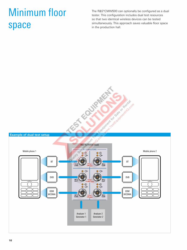
Example of dual test setup
¸CMW500 (dual)
GSMWCDMA
Mobile phone 1
Analyzer 1Generator 1
Analyzer 2Generator 2
BT
DVB
GSMWCDMA
Mobile phone 2
DVB
BT
The R&S®CMW500 can optionally be configured as a dual tester. This configuration includes dual test resources so that two identical wireless devices can be tested simultaneously. This approach saves valuable floor space in the production hall.
Minimum floor space
10
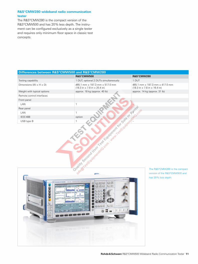
The R&S®CMW280 is the compact
version of the R&S®CMW500 and
has 20 % less depth.
R&S®CMW280 wideband radio communication testerThe R&S®CMW280 is the compact version of the R&S®CMW500 and has 20 % less depth. The instru-ment can be configured exclusively as a single tester and requires only minimum floor space in classic test concepts.
Differences between R&S®CMW500 and R&S®CMW280R&S®CMW500 R&S®CMW280
Testing capability 1 DUT, optional 2 DUTs simultaneously 1 DUT
Dimensions (W × H × D) 465.1 mm × 197.3 mm × 517.0 mm(18.3 in × 7.8 in × 20.4 in)
465.1 mm × 197.3 mm × 417.0 mm(18.3 in × 7.8 in × 16.4 in)
Weight with typical options approx. 18 kg (approx. 40 lb) approx. 14 kg (approx. 31 lb)
Remote control interfaces
Front panel
LAN 1 –
Rear panel
LAN 1 1
IEEE 488 option –
USB type B 1 –
Rohde & Schwarz R&S®CMW500 Wideband Radio Communication Tester 11

R&S®UCS calibration system.
Reduced operating costs due to 24-month calibration interval
Selectable calibration interval of either 12 or 24 months. Users can optimize costs to achieve high absolute accu-racy or minimum test and measurement operating costs.
Relevant R&S®CMW500 RF level uncertainty12-month calibration interval:
Analyzer <0.50 dB J
Generator <0.60 dB J
24-month calibration interval:Analyzer <0.70 dB J
Generator <0.80 dB J
12

Irvine, CATijuana
GuadalajaraMonterrey
Mexico City
Beaverton,OR
USA
Irving, TX
Columbia, MD
Ottawa
Mexico
Brasilia
Rio de Janeiro
Chile Argentina Uruguay
Sao Paul o
South Africa
Tanzania
Kenya
Sudan
Egypt
TunisiaMalta
Cyprus Lebanon Syria
Jordan
Nigeria
Algeria
Ghana
Kuwait
Oman
Azerbaijan
Kazakhstan
Pakistan
SaudiArabia United
Arab. Emirates
Delhi
Hyderabad
Mumbai
Abu Dhabi, Dubai
Bangalore
Nepal Bangladesh
Sri Lanka
China Chengdu
Xi´an
Beijing
Osaka Tokyo
Seoul
TaipeiKaohsiung
Kanagawa
Shanghai
Hong Kong
Makati CityBangkok
Kuala Lumpur
ShenzhenGuangzhouHanoi
Vietnam
Taiwan
Thailand
Malaysia
Singapore
Brunei
Indonesia
Philippines
Japan
Australia
New Zealand
India
Korea
Colombia
Brazil
SlovkiaCzech R.
HungaryRomania
BulgariaMacedonia Serbia
Netherl.
UK Denmark
Norway Sweden
Finland RussianFederation
Belgium
Spain
Portugal
France Switzerland Austria
Greece TurkeyItaly
Slovenia
Poland
Ukraine
Munich, Germany
Headquarters
Canada
Manaos
ParaguayAsuncion
EstoniaLatviaLithuaniaIreland
Morocco
Botswana
Libya
MadagascarZambia Malawi
Mozambique
Uganda
Namibia
Mongolia
Islamabad
Karachi
ChennaiHo Chi Minh City
GumiSaitama
Perth
Melbourne
CanberraSydney
Schaumburg,IL
From pre-sale to service. At your doorstep.
The Rohde & Schwarz network in over 70 countries ensures optimum on-site support by highly qualified experts. The user risks are reduced to a minimum at all stages of the project:
Solution finding/purchase J
Technical start-up/application development/integration J
Training J
Operation/calibration/repair J
Rohde & Schwarz R&S®CMW500 Wideband Radio Communication Tester 13
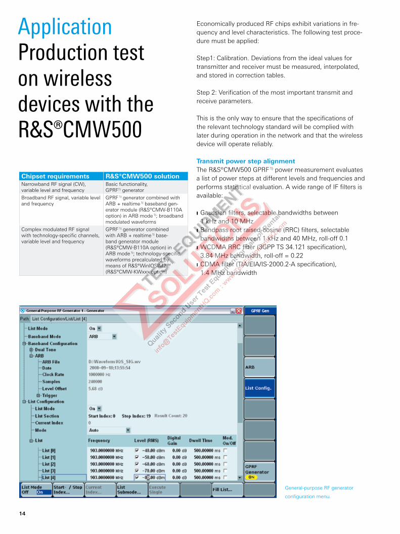
General-purpose RF generator
configuration menu.
Application Production test on wireless devices with the R&S®CMW500
Economically produced RF chips exhibit variations in fre-quency and level characteristics. The following test proce-dure must be applied:
Step1: Calibration. Deviations from the ideal values for transmitter and receiver must be measured, interpolated, and stored in correction tables.
Step 2: Verification of the most important transmit and receive parameters.
This is the only way to ensure that the specifications of the relevant technology standard will be complied with later during operation in the network and that the wireless device will operate reliably.
Transmit power step alignmentThe R&S®CMW500 GPRF 1) power measurement evaluates a list of power steps at different levels and frequencies and performs statistical evaluation. A wide range of IF filters is available:
Gaussian filters, selectable bandwidths between J
1 kHz and 10 MHzBandpass root raised-cosine (RRC) filters, selectable J
bandwidths between 1 kHz and 40 MHz, roll-off 0.1WCDMA RRC filter (3GPP TS 34.121 specification), J
3.84 MHz bandwidth, roll-off = 0.22CDMA filter (TIA/EIA/IS-2000.2-A specification), J
1.4 MHz bandwidth
Chipset requirements R&S®CMW500 solutionNarrowband RF signal (CW), variable level and frequency
Basic functionality, GPRF1) generator
Broadband RF signal, variable level and frequency
GPRF 1) generator combined with ARB + realtime 1) baseband gen-erator module (R&S®CMW-B110A option) in ARB mode 1); broadband modulated waveforms
Complex modulated RF signal with technology-specific channels, variable level and frequency
GPRF 1) generator combined with ARB + realtime 1) base-band generator module (R&S®CMW-B110A option) in ARB mode 1); technology-specific waveforms precalculated by means of R&S®WinIQSIM2™ (R&S®CMW-KWxxx option)
14
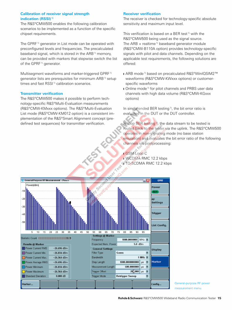
General-purpose RF power
measurement menu.
Calibration of receiver signal strength indication (RSSI) 1) The R&S®CMW500 enables the following calibration scenarios to be implemented as a function of the specific chipset requirements.
The GPRF 1) generator in List mode can be operated with preconfigured levels and frequencies. The precalculated baseband signal, which is stored in the ARB 1) memory, can be provided with markers that stepwise switch the list of the GPRF 1) generator.
Multisegment waveforms and marker-triggered GPRF 1) generator lists are prerequisites for minimum ARB 1) setup times and fast RSSI 1) calibration scenarios.
Transmitter verificationThe R&S®CMW500 makes it possible to perform tech-nology-specific R&S®Multi-Evaluation measurements (R&S®CMW-KMxxx options). The R&S®Multi-Evaluation List mode (R&S®CMW-KM012 option) is a consistent im-plementation of the R&S®Smart Alignment concept (pre-defined test sequences) for transmitter verification.
Receiver verificationThe receiver is checked for technology-specific absolute sensitivity and maximum input level.
This verification is based on a BER test 1) with the R&S®CMW500 being used as the signal source. The ARB + realtime 1) baseband generator module (R&S®CMW-B110A option) provides technology-specific signals with pilot and data channels. Depending on the applicable test requirements, the following solutions are offered:
ARB mode J 1) based on precalculated R&S®WinIQSIM2™ waveforms (R&S®CMW-KWxxx options) or customer-specific waveformsOnline mode J 1) for pilot channels and PRBS user data channels with high data volume (R&S®CMW-KGxxx options)
In single-ended BER testing 1), the bit error ratio is evaluated in the DUT or the DUT controller.
In loop BER testing 1), the data stream to be tested is routed back to the tester via the uplink. The R&S®CMW500 operates in non-signaling mode (no base station emulation) and evaluates the bit error ratio of the following channels via postprocessing:
GSM Loop C J
WCDMA RMC 12.2 kbps J
TD-SCDMA RMC 12.2 kbps J
Rohde & Schwarz R&S®CMW500 Wideband Radio Communication Tester 15

Time mask screen:
GSM/GPRS/EDGE TX measure-
ment – R&S®Multi-Evaluation.
R&S®CMW-KM200 measurement personality 2)
Burst power J
Time mask J
I/Q origin offset/imbalance (8PSK modulation scheme) J
Error vector magnitude (8PSK modulation scheme) J
Magnitude error (8PSK modulation scheme) J
Phase error J
Frequency error (GMSK modulation scheme) J
Spectrum due to modulation J
Spectrum due to switching J
TX measurements GSM/GPRS/EDGE
2) R&S®Multi-Evaluation List mode supported in combination with R&S®CMW-KM012 option.
16

Overview screen:
WCDMA TX measurement –
R&S®Multi- Evaluation.
WCDMAR&S®CMW-KM400 measurement personality 2)
UE power measurements can be applied to OFF/max./ J
min. powerError vector magnitude J
Magnitude error J
Phase error J
I/Q origin offset/imbalance J
Frequency error J
Phase discontinuity J
Adjacent channel leakage ratio J
Spectrum emission mask J
Occupied bandwidth J
Code domain power J
Peak code domain error J
Code domain error J
Code domain power monitor J
Code domain error monitor J
HSPA extensionsR&S®CMW-KM401 measurement personality
Half-slot measurements J
Modulation analysis of HSPA channels J
Code domain power measurement of HSPA channels J
Code domain error versus slot measurement of HSPA J
channelsHS-DPCCH power control J
Phase discontinuity J
R&S®CMW-KM403 measurement personality
16QAM modulation analysis J
Relative code domain error (in the pipeline) J
HSPA+ extensions
Rohde & Schwarz R&S®CMW500 Wideband Radio Communication Tester 17

Overview screen:
LTE FDD TX measurement –
R&S®Multi-Evaluation.
R&S®CMW-KM500 measurement personality
Transmit power J
Peak power J
Resource block power J
Error vector magnitude J
Magnitude error J
Phase error J
Frequency error J
I/Q origin offset J
I/Q constellation diagram J
In-band emissions J
Spectrum flatness J
Adjacent channel leakage ratio J
Occupied bandwidth J
Spectrum emission mask J
LTE FDD
18
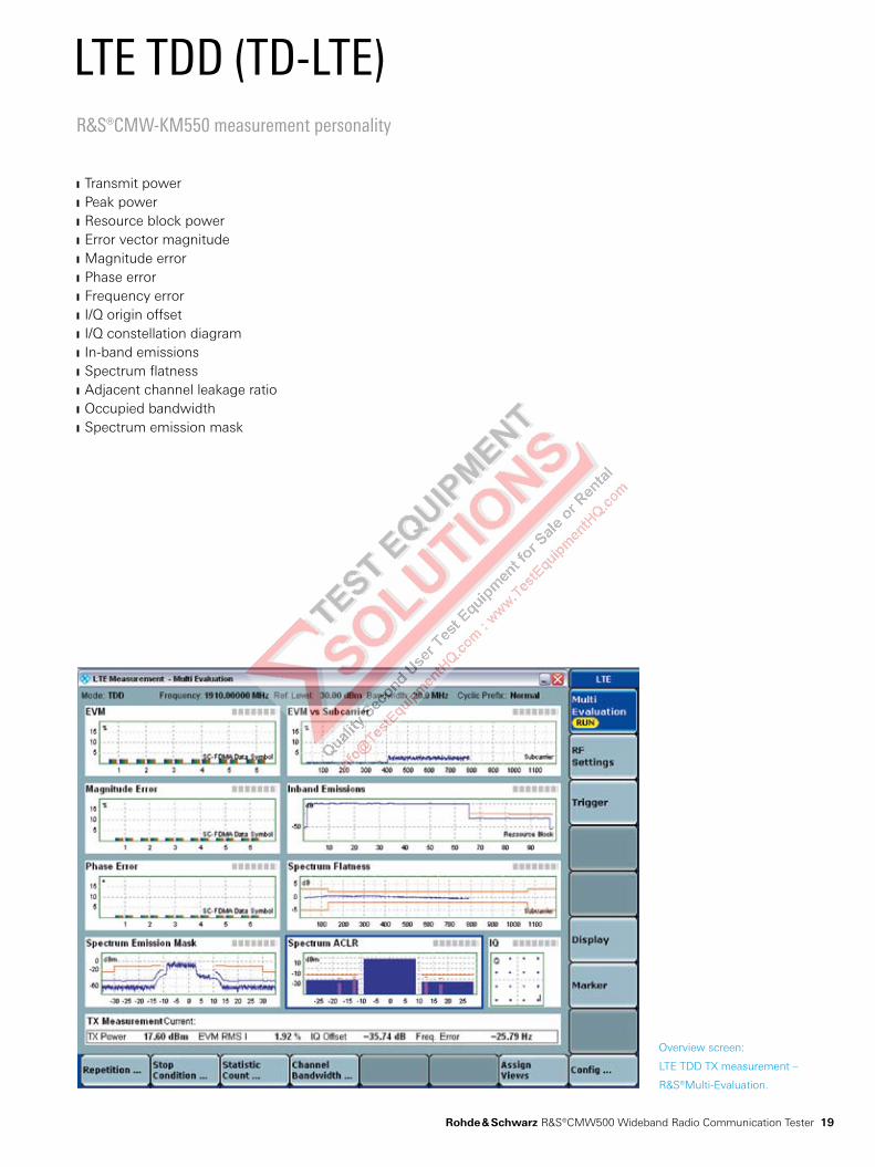
Overview screen:
LTE TDD TX measurement –
R&S®Multi-Evaluation.
R&S®CMW-KM550 measurement personality
Transmit power J
Peak power J
Resource block power J
Error vector magnitude J
Magnitude error J
Phase error J
Frequency error J
I/Q origin offset J
I/Q constellation diagram J
In-band emissions J
Spectrum flatness J
Adjacent channel leakage ratio J
Occupied bandwidth J
Spectrum emission mask J
LTE TDD (TD-LTE)
Rohde & Schwarz R&S®CMW500 Wideband Radio Communication Tester 19
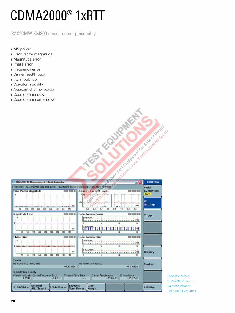
Overview screen:
CDMA2000® 1xRTT
TX measurement –
R&S®Multi-Evaluation.
R&S®CMW-KM800 measurement personality
MS power J
Error vector magnitude J
Magnitude error J
Phase error J
Frequency error J
Carrier feedthrough J
I/Q imbalance J
Waveform quality J
Adjacent channel power J
Code domain power J
Code domain error power J
CDMA2000® 1xRTT
20
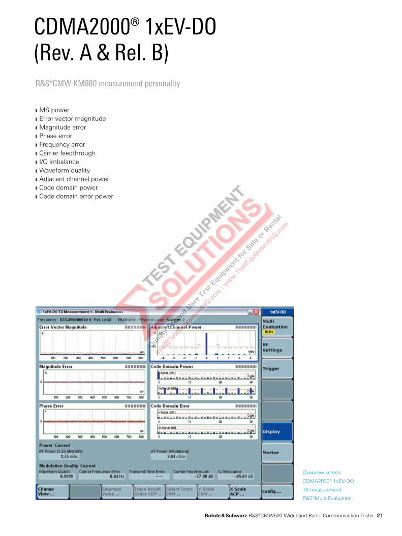
Overview screen:
CDMA2000® 1xEV-DO
TX measurement –
R&S®Multi-Evaluation.
R&S®CMW-KM880 measurement personality
MS power J
Error vector magnitude J
Magnitude error J
Phase error J
Frequency error J
Carrier feedthrough J
I/Q imbalance J
Waveform quality J
Adjacent channel power J
Code domain power J
Code domain error power J
CDMA2000® 1xEV-DO (Rev. A & Rel. B)
Rohde & Schwarz R&S®CMW500 Wideband Radio Communication Tester 21

Overview screen:
Mobile WiMAX™ TX measure-
ment – R&S®Multi-Evaluation
(R&S®CMW-KM701 option).
R&S®CMW-KM700 measurement personality
Burst power J
Time mask J
Crest factor J
Subcarrier power J
Center frequency error J
Error vector magnitude (unmodulated) J
I/Q offset/imbalance J
Gain imbalance J
Qudrature error J
Sample clock error J
Spectral flatness (neighbor) J
Occupied bandwidth J
Adjacent channel power J
Spectrum emission mask J
Mobile WiMAX™
22
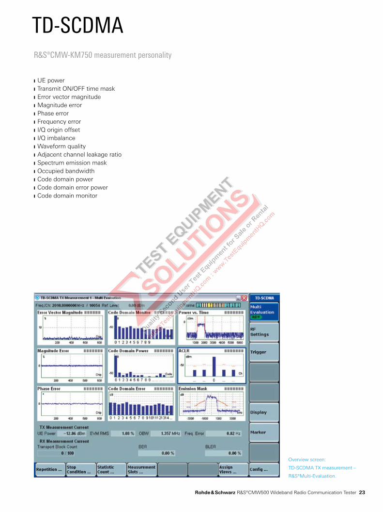
Overview screen:
TD-SCDMA TX measurement –
R&S®Multi-Evaluation.
R&S®CMW-KM750 measurement personality
UE power J
Transmit ON/OFF time mask J
Error vector magnitude J
Magnitude error J
Phase error J
Frequency error J
I/Q origin offset J
I/Q imbalance J
Waveform quality J
Adjacent channel leakage ratio J
Spectrum emission mask J
Occupied bandwidth J
Code domain power J
Code domain error power J
Code domain monitor J
TD-SCDMA
Rohde & Schwarz R&S®CMW500 Wideband Radio Communication Tester 23
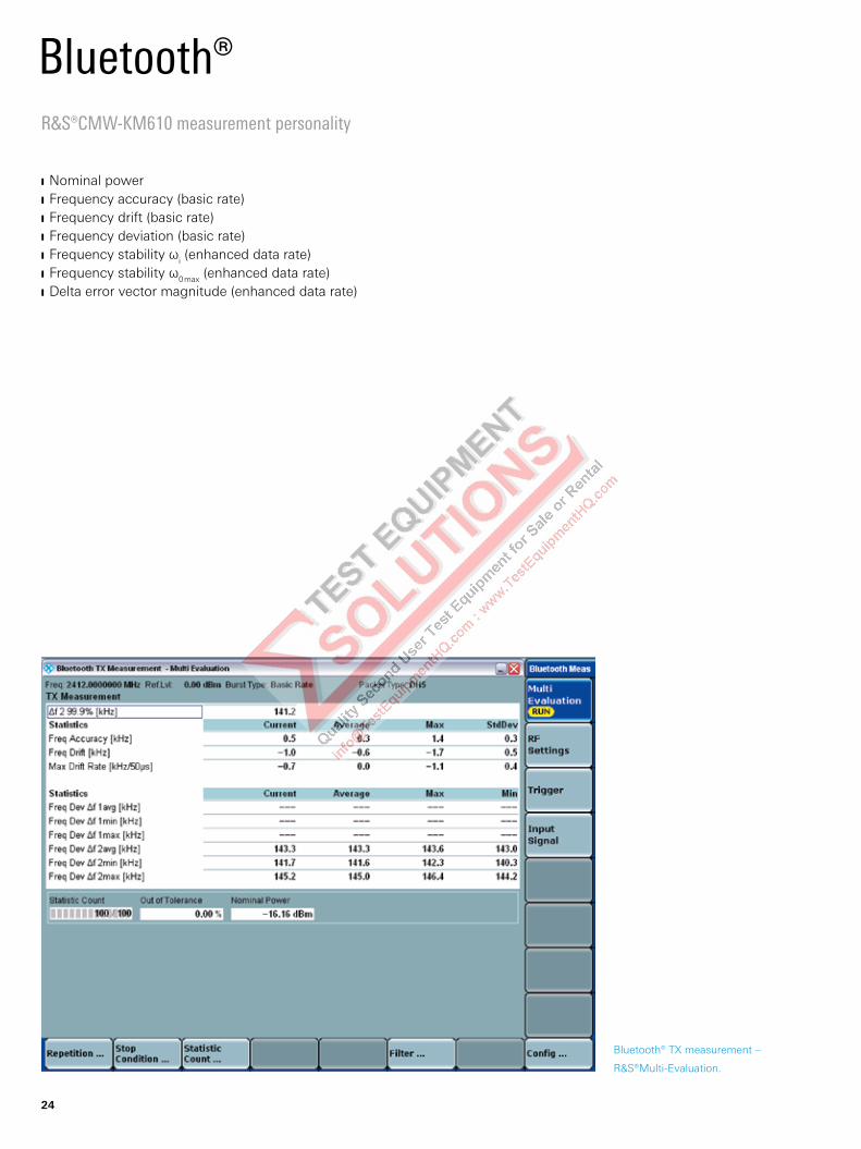
Bluetooth® TX measurement –
R&S®Multi-Evaluation.
R&S®CMW-KM610 measurement personality
Nominal power J
Frequency accuracy (basic rate) J
Frequency drift (basic rate) J
Frequency deviation (basic rate) J
Frequency stability ω J i (enhanced data rate)Frequency stability ω J 0 max (enhanced data rate) Delta error vector magnitude (enhanced data rate) J
Bluetooth®
24
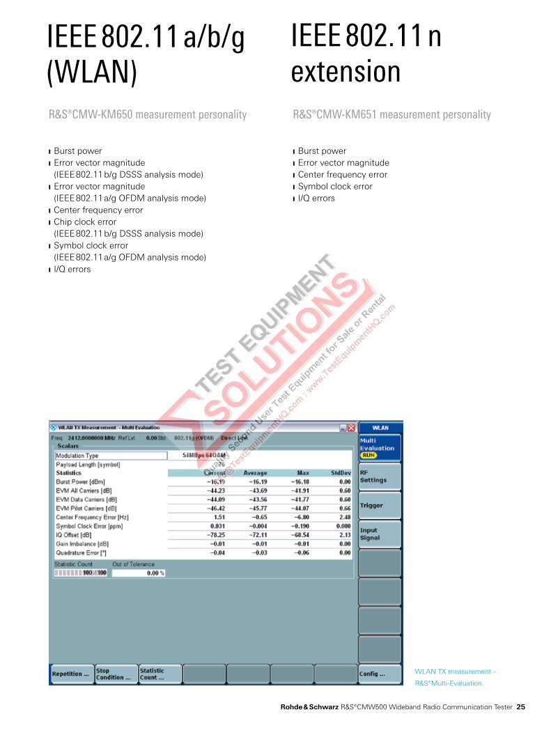
WLAN TX measurement –
R&S®Multi-Evaluation.
R&S®CMW-KM650 measurement personality
Burst power J
Error vector magnitude J
(IEEE 802.11 b/g DSSS analysis mode)Error vector magnitude J
(IEEE 802.11 a/g OFDM analysis mode)Center frequency error J
Chip clock error J
(IEEE 802.11 b/g DSSS analysis mode)Symbol clock error J
(IEEE 802.11 a/g OFDM analysis mode)I/Q errors J
IEEE 802.11 a/b/g (WLAN)
R&S®CMW-KM651 measurement personality
Burst power J
Error vector magnitude J
Center frequency error J
Symbol clock error J
I/Q errors J
IEEE 802.11 n extension
Rohde & Schwarz R&S®CMW500 Wideband Radio Communication Tester 25
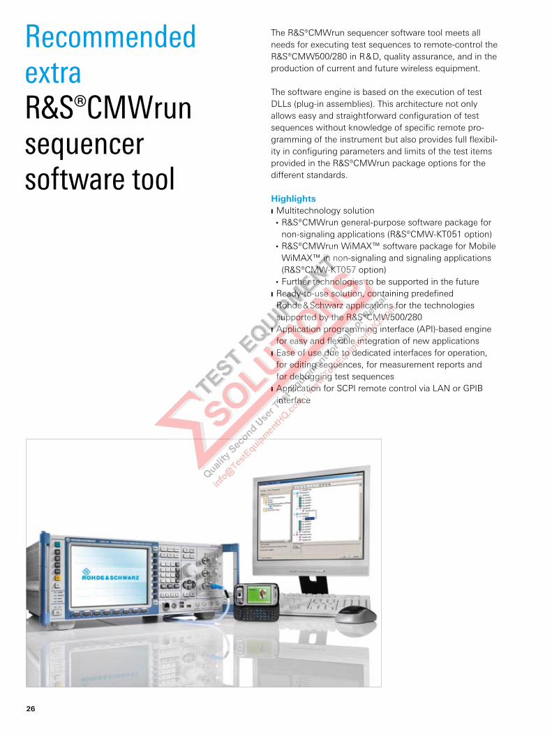
Recommended extra R&S®CMWrun sequencer software tool
The R&S®CMWrun sequencer software tool meets all needs for executing test sequences to remote-control the R&S®CMW500/280 in R & D, quality assurance, and in the production of current and future wireless equipment.
The software engine is based on the execution of test DLLs (plug-in assemblies). This architecture not only allows easy and straightforward configuration of test sequences without knowledge of specific remote pro-gramming of the instrument but also provides full flexibil-ity in configuring parameters and limits of the test items provided in the R&S®CMWrun package options for the different standards.
HighlightsMultitechnology solution J
R&S®CMWrun general-purpose software package for W
non-signaling applications (R&S®CMW-KT051 option)R&S®CMWrun WiMAX™ software package for Mobile W
WiMAX™ in non-signaling and signaling applications (R&S®CMW-KT057 option)Further technologies to be supported in the future W
Ready-to-use solution, containing predefined J
Rohde & Schwarz applications for the technologies supported by the R&S®CMW500/280Application programming interface (API)-based engine J
for easy and flexible integration of new applicationsEase of use due to dedicated interfaces for operation, J
for editing sequences, for measurement reports and for debugging test sequences Application for SCPI remote control via LAN or GPIB J
interface
26

R&S®CMWrun framework
Applications
Operatorinterface
(parametric)
Sequenceeditor
(if.loop, whilecommands)
Measurementreport
(.pdf, .xml)
Sequencedebugger
(single-stepmode)
Processlog view
ApplicationsApplications
¸CMWrun engine(framework)
Automated report options for secure quality management in line with international quality standardsMeasurement reports are generated online during test execution or after the end of the test, if priority is placed on measurement speed. In addition, different export for-mats are available as a global setting or for a specific test sequence. Test reports can be stored automatically after every test routine and automatically exported to a defined report format. This feature allows a high level of automa-tion in production lines, e.g. by providing the interfaces for standard statistical tools.
Flexible optioning concept for instrument- or PC-based licensing The R&S®CMWrun sequencer software can be installed ei-ther on an external PC (Windows® XP PC) or directly on an R&S®CMW500/280. A smart card is required for licensing if the external PC is used for R&S®CMWrun licensing. This allows full flexibility with different instruments. For best performance, the PC installation is recommended.
Key featuresReady-to-use solution for configuring a test sequence with just a few mouse clicksThe straightforward graphical interface makes it easy to program test sequences. The user can define custom-ized test sequences for any of the supported mobile communications standards in the R&S®CMW500/280 with just a few mouse clicks. Programming knowledge is not required.
Test sequence editor for high flexibility, from regression testing to simple test sequences The R&S®CMWrun sequencer software lets the user integrate basic programming commands such as “if”, “while” or ”loop” to control the test sequence, allowing test sequences to be executed interactively. Such control features are integrated into the test sequence in a separate “edit test sequence menu” view to protect the configura-tion in the standard test sequence view.
Control of all parameters in one viewInput fields are available for configuring all essential RF parameters; tolerances for the individual measurements can be changed. If no special requirements for tolerances exist, the software uses the tolerances defined in the specification. A customer-specific testing scenario can thus be configured very easily.
Rohde & Schwarz R&S®CMW500 Wideband Radio Communication Tester 27
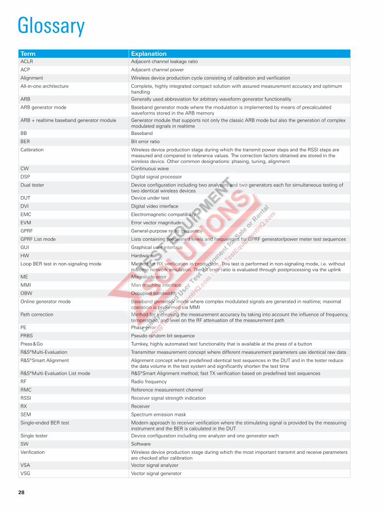
GlossaryTerm ExplanationACLR Adjacent channel leakage ratio
ACP Adjacent channel power
Alignment Wireless device production cycle consisting of calibration and verification
All-in-one architecture Complete, highly integrated compact solution with assured measurement accuracy and optimum handling
ARB Generally used abbreviation for arbitrary waveform generator functionality
ARB generator mode Baseband generator mode where the modulation is implemented by means of precalculated waveforms stored in the ARB memory
ARB + realtime baseband generator module Generator module that supports not only the classic ARB mode but also the generation of complex modulated signals in realtime
BB Baseband
BER Bit error ratio
Calibration Wireless device production stage during which the transmit power steps and the RSSI steps are measured and compared to reference values. The correction factors obtained are stored in the wireless device. Other common designations: phasing, tuning, alignment
CW Continuous wave
DSP Digital signal processor
Dual tester Device configuration including two analyzers and two generators each for simultaneous testing of two identical wireless devices
DUT Device under test
DVI Digital video interface
EMC Electromagnetic compatibility
EVM Error vector magnitude
GPRF General-purpose radio frequency
GPRF List mode Lists containing predefined levels and frequencies for GPRF generator/power meter test sequences
GUI Graphical user interface
HW Hardware
Loop BER test in non-signaling mode Method for RX verification in production. This test is performed in non-signaling mode, i.e. without realtime network emulation. The bit error ratio is evaluated through postprocessing via the uplink
ME Magnitude error
MMI Man machine interface
OBW Occupied bandwidth
Online generator mode Baseband generator mode where complex modulated signals are generated in realtime; maximal operation is performed via MMI
Path correction Method for increasing the measurement accuracy by taking into account the influence of frequency, temperature, and level on the RF attenuation of the measurement path
PE Phase error
PRBS Pseudo random bit sequence
Press & Go Turnkey, highly automated test functionality that is available at the press of a button
R&S®Multi- Evaluation Transmitter measurement concept where different measurement parameters use identical raw data
R&S®Smart Alignment Alignment concept where predefined identical test sequences in the DUT and in the tester reduce the data volume in the test system and significantly shorten the test time
R&S®Multi-Evaluation List mode R&S®Smart Alignment method; fast TX verification based on predefined test sequences
RF Radio frequency
RMC Reference measurement channel
RSSI Receiver signal strength indication
RX Receiver
SEM Spectrum emission mask
Single-ended BER test Modern approach to receiver verification where the stimulating signal is provided by the measuring instrument and the BER is calculated in the DUT
Single tester Device configuration including one analyzer and one generator each
SW Software
Verification Wireless device production stage during which the most important transmit and receive parameters are checked after calibration
VSA Vector signal analyzer
VSG Vector signal generator
28
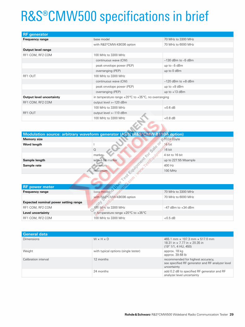
R&S®CMW500 specifications in briefRF generatorFrequency range base model 70 MHz to 3300 MHz
with R&S®CMW-KB036 option 70 MHz to 6000 MHz
Output level range
RF1 COM, RF2 COM 100 MHz to 3300 MHz
continuous wave (CW) –130 dBm to –5 dBm
peak envelope power (PEP) up to –5 dBm
overranging (PEP) up to 0 dBm
RF1 OUT 100 MHz to 3300 MHz
continuous wave (CW) –120 dBm to +8 dBm
peak envelope power (PEP) up to +8 dBm
overranging (PEP) up to +13 dBm
Output level uncertainty in temperature range +20 °C to +35 °C, no overranging
RF1 COM, RF2 COM output level >–120 dBm
100 MHz to 3300 MHz <0.6 dB
RF1 OUT output level >–110 dBm
100 MHz to 3300 MHz <0.8 dB
Modulation source: arbitrary waveform generator (ARB) (R&S®CMW-B110A option)Memory size 1024 Gbyte
Word length I 16 bit
Q 16 bit
marker 4 bit to 16 bit
Sample length with 4-bit marker up to 227.55 Msample
Sample rate minimum 400 Hz
maximum 100 MHz
RF power meterFrequency range base model 70 MHz to 3300 MHz
with R&S®CMW-KB036 option 70 MHz to 6000 MHz
Expected nominal power setting range
RF1 COM, RF2 COM 100 MHz to 3300 MHz –47 dBm to +34 dBm
Level uncertainty in temperature range +20 °C to +35 °C
RF1 COM, RF2 COM 100 MHz to 3300 MHz <0.5 dB
General dataDimensions W × H × D 465.1 mm × 197.3 mm × 517.0 mm
18.31 in × 7.77 in × 20.35 in(19" 1/1, 4 HU, 450)
Weight with typical options (single tester) approx. 18 kgapprox. 39.68 lb
Calibration interval 12 months recommended for highest accuracy,see specified RF generator and RF analyzer level uncertainty
24 months add 0.2 dB to specified RF generator and RF analyzer level uncertainty
Rohde & Schwarz R&S®CMW500 Wideband Radio Communication Tester 29
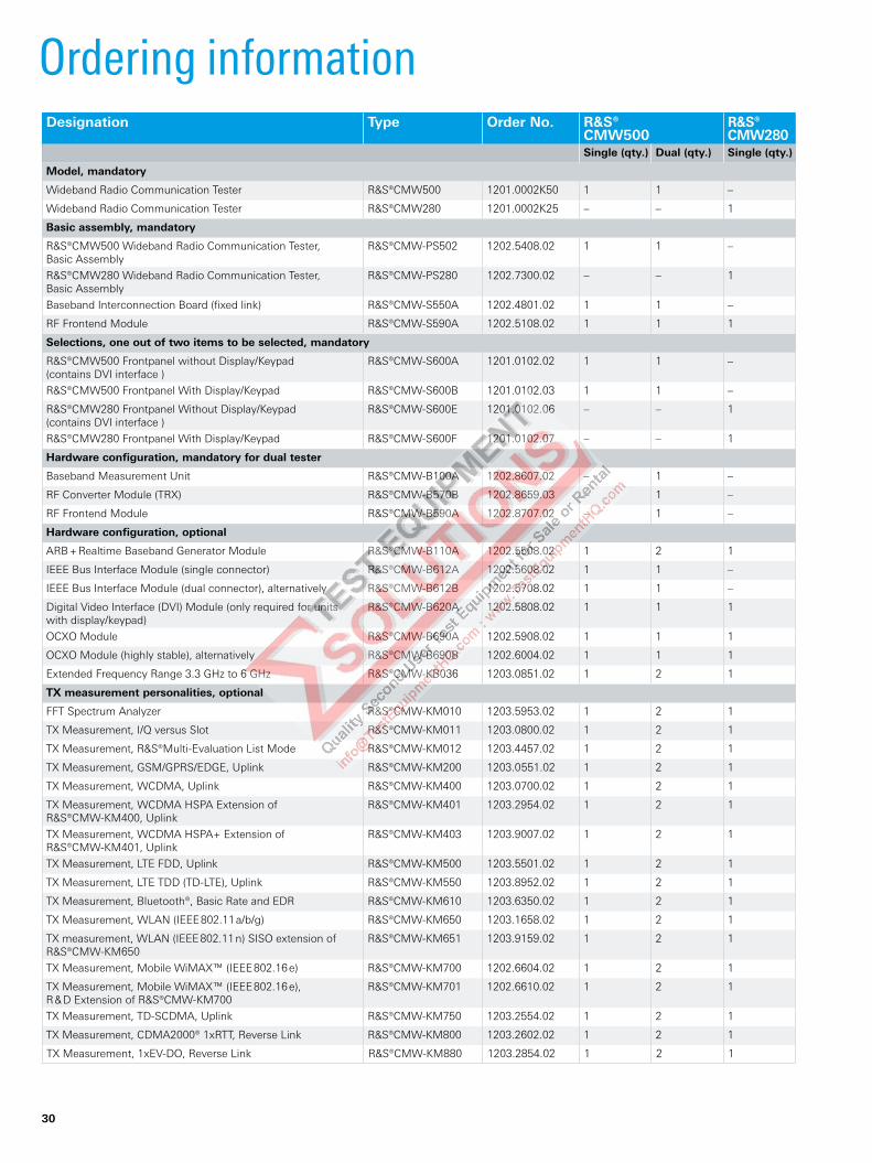
Ordering informationDesignation Type Order No. R&S®
CMW500R&S® CMW280
Single (qty.) Dual (qty.) Single (qty.)
Model, mandatory
Wideband Radio Communication Tester R&S®CMW500 1201.0002K50 1 1 –
Wideband Radio Communication Tester R&S®CMW280 1201.0002K25 – – 1
Basic assembly, mandatory
R&S®CMW500 Wideband Radio Communication Tester, Basic Assembly
R&S®CMW-PS502 1202.5408.02 1 1 –
R&S®CMW280 Wideband Radio Communication Tester, Basic Assembly
R&S®CMW-PS280 1202.7300.02 – – 1
Baseband Interconnection Board (fixed link) R&S®CMW-S550A 1202.4801.02 1 1 –
RF Frontend Module R&S®CMW-S590A 1202.5108.02 1 1 1
Selections, one out of two items to be selected, mandatory
R&S®CMW500 Frontpanel without Display/Keypad (contains DVI interface )
R&S®CMW-S600A 1201.0102.02 1 1 –
R&S®CMW500 Frontpanel With Display/Keypad R&S®CMW-S600B 1201.0102.03 1 1 –
R&S®CMW280 Frontpanel Without Display/Keypad (contains DVI interface )
R&S®CMW-S600E 1201.0102.06 – – 1
R&S®CMW280 Frontpanel With Display/Keypad R&S®CMW-S600F 1201.0102.07 – – 1
Hardware configuration, mandatory for dual tester
Baseband Measurement Unit R&S®CMW-B100A 1202.8607.02 – 1 –
RF Converter Module (TRX) R&S®CMW-B570B 1202.8659.03 – 1 –
RF Frontend Module R&S®CMW-B590A 1202.8707.02 – 1 –
Hardware configuration, optional
ARB + Realtime Baseband Generator Module R&S®CMW-B110A 1202.5508.02 1 2 1
IEEE Bus Interface Module (single connector) R&S®CMW-B612A 1202.5608.02 1 1 –
IEEE Bus Interface Module (dual connector), alternatively R&S®CMW-B612B 1202.5708.02 1 1 –
Digital Video Interface (DVI) Module (only required for units with display/keypad)
R&S®CMW-B620A 1202.5808.02 1 1 1
OCXO Module R&S®CMW-B690A 1202.5908.02 1 1 1
OCXO Module (highly stable), alternatively R&S®CMW-B690B 1202.6004.02 1 1 1
Extended Frequency Range 3.3 GHz to 6 GHz R&S®CMW-KB036 1203.0851.02 1 2 1
TX measurement personalities, optional
FFT Spectrum Analyzer R&S®CMW-KM010 1203.5953.02 1 2 1
TX Measurement, I/Q versus Slot R&S®CMW-KM011 1203.0800.02 1 2 1
TX Measurement, R&S®Multi-Evaluation List Mode R&S®CMW-KM012 1203.4457.02 1 2 1
TX Measurement, GSM/GPRS/EDGE, Uplink R&S®CMW-KM200 1203.0551.02 1 2 1
TX Measurement, WCDMA, Uplink R&S®CMW-KM400 1203.0700.02 1 2 1
TX Measurement, WCDMA HSPA Extension of R&S®CMW-KM400, Uplink
R&S®CMW-KM401 1203.2954.02 1 2 1
TX Measurement, WCDMA HSPA+ Extension of R&S®CMW-KM401, Uplink
R&S®CMW-KM403 1203.9007.02 1 2 1
TX Measurement, LTE FDD, Uplink R&S®CMW-KM500 1203.5501.02 1 2 1
TX Measurement, LTE TDD (TD-LTE), Uplink R&S®CMW-KM550 1203.8952.02 1 2 1
TX Measurement, Bluetooth®, Basic Rate and EDR R&S®CMW-KM610 1203.6350.02 1 2 1
TX Measurement, WLAN (IEEE 802.11 a/b/g) R&S®CMW-KM650 1203.1658.02 1 2 1
TX measurement, WLAN (IEEE 802.11 n) SISO extension of R&S®CMW-KM650
R&S®CMW-KM651 1203.9159.02 1 2 1
TX Measurement, Mobile WiMAX™ (IEEE 802.16 e) R&S®CMW-KM700 1202.6604.02 1 2 1
TX Measurement, Mobile WiMAX™ (IEEE 802.16 e), R & D Extension of R&S®CMW-KM700
R&S®CMW-KM701 1202.6610.02 1 2 1
TX Measurement, TD-SCDMA, Uplink R&S®CMW-KM750 1203.2554.02 1 2 1
TX Measurement, CDMA2000® 1xRTT, Reverse Link R&S®CMW-KM800 1203.2602.02 1 2 1
TX Measurement, 1xEV-DO, Reverse Link R&S®CMW-KM880 1203.2854.02 1 2 1
30
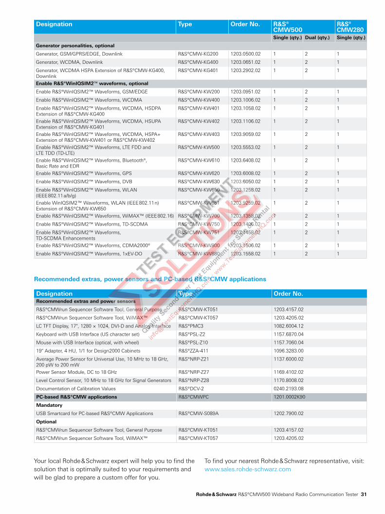
Designation Type Order No. R&S®CMW500
R&S® CMW280
Single (qty.) Dual (qty.) Single (qty.)
Generator personalities, optional
Generator, GSM/GPRS/EDGE, Downlink R&S®CMW-KG200 1203.0500.02 1 2 1
Generator, WCDMA, Downlink R&S®CMW-KG400 1203.0651.02 1 2 1
Generator, WCDMA HSPA Extension of R&S®CMW-KG400, Downlink
R&S®CMW-KG401 1203.2902.02 1 2 1
Enable R&S®WinIQSIM2™ waveforms, optional
Enable R&S®WinIQSIM2™ Waveforms, GSM/EDGE R&S®CMW-KW200 1203.0951.02 1 2 1
Enable R&S®WinIQSIM2™ Waveforms, WCDMA R&S®CMW-KW400 1203.1006.02 1 2 1
Enable R&S®WinIQSIM2™ Waveforms, WCDMA, HSDPA Extension of R&S®CMW-KG400
R&S®CMW-KW401 1203.1058.02 1 2 1
Enable R&S®WinIQSIM2™ Waveforms, WCDMA, HSUPA Extension of R&S®CMW-KG401
R&S®CMW-KW402 1203.1106.02 1 2 1
Enable R&S®WinIQSIM2™ Waveforms, WCDMA, HSPA+ Extension of R&S®CMW-KW401 or R&S®CMW-KW402
R&S®CMW-KW403 1203.9059.02 1 2 1
Enable R&S®WinIQSIM2™ Waveforms, LTE FDD and LTE TDD (TD-LTE)
R&S®CMW-KW500 1203.5553.02 1 2 1
Enable R&S®WinIQSIM2™ Waveforms, Bluetooth®, Basic Rate and EDR
R&S®CMW-KW610 1203.6408.02 1 2 1
Enable R&S®WinIQSIM2™ Waveforms, GPS R&S®CMW-KW620 1203.6008.02 1 2 1
Enable R&S®WinIQSIM2™ Waveforms, DVB R&S®CMW-KW630 1203.6050.02 1 2 1
Enable R&S®WinIQSIM2™ Waveforms, WLAN (IEEE 802.11 a/b/g)
R&S®CMW-KW650 1203.1258.02 1 2 1
Enable WinIQSIM2™ Waveforms, WLAN (IEEE 802.11 n) Extension of R&S®CMW-KW650
R&S®CMW-KW651 1203.9259.02 1 2 1
Enable R&S®WinIQSIM2™ Waveforms, WiMAX™ (IEEE 802.16) R&S®CMW-KW700 1203.1358.02 1 2 1
Enable R&S®WinIQSIM2™ Waveforms, TD-SCDMA R&S®CMW-KW750 1203.1406.02 1 2 1
Enable R&S®WinIQSIM2™ Waveforms, TD-SCDMA Enhancements
R&S®CMW-KW751 1203.1458.02 1 2 1
Enable R&S®WinIQSIM2™ Waveforms, CDMA2000® R&S®CMW-KW800 1203.1506.02 1 2 1
Enable R&S®WinIQSIM2™ Waveforms, 1xEV-DO R&S®CMW-KW880 1203.1558.02 1 2 1
Recommended extras, power sensors and PC-based R&S®CMW applications
Designation Type Order No.Recommended extras and power sensors
R&S®CMWrun Sequencer Software Tool, General Purpose R&S®CMW-KT051 1203.4157.02
R&S®CMWrun Sequencer Software Tool, WiMAX™ R&S®CMW-KT057 1203.4205.02
LC TFT Display, 17", 1280 × 1024, DVI-D and Analog Interface R&S®PMC3 1082.6004.12
Keyboard with USB Interface (US character set) R&S®PSL-Z2 1157.6870.04
Mouse with USB Interface (optical, with wheel) R&S®PSL-Z10 1157.7060.04
19" Adapter, 4 HU, 1/1 for Design2000 Cabinets R&S®ZZA-411 1096.3283.00
Average Power Sensor for Universal Use, 10 MHz to 18 GHz, 200 pW to 200 mW
R&S®NRP-Z21 1137.6000.02
Power Sensor Module, DC to 18 GHz R&S®NRP-Z27 1169.4102.02
Level Control Sensor, 10 MHz to 18 GHz for Signal Generators R&S®NRP-Z28 1170.8008.02
Documentation of Calibration Values R&S®DCV-2 0240.2193.08
PC-based R&S®CMW applications R&S®CMWPC 1201.0002K90
Mandatory
USB Smartcard for PC-based R&S®CMW Applications R&S®CMW-S089A 1202.7900.02
Optional
R&S®CMWrun Sequencer Software Tool, General Purpose R&S®CMW-KT051 1203.4157.02
R&S®CMWrun Sequencer Software Tool, WiMAX™ R&S®CMW-KT057 1203.4205.02
Your local Rohde & Schwarz expert will help you to find the solution that is optimally suited to your requirements and will be glad to prepare a custom offer for you.
To find your nearest Rohde & Schwarz representative, visit:www.sales.rohde-schwarz.com
Rohde & Schwarz R&S®CMW500 Wideband Radio Communication Tester 31
Rohde & Schwarz GmbH & Co. KGMühldorfstraße 15 | 81671 MünchenPhone +49 89 41 290 | Fax +49 89 41 29 121 64
www.rohde-schwarz.com
R&S® is a registered trademark of Rohde & Schwarz GmbH & Co. KG Trade names are trademarks of the owners | Printed in Germany (ch) PD 5213.9211.12 | Version 04.00 | July 2009 | R&S®CMW500 Data without tolerance limits is not binding | Subject to change *0.14 €/min within German wireline network; rates may vary in other networks (wireline and mobile) and countries.
For data sheet, see PD 5213.9211.22
and www.rohde-schwarz.com
Service you can rely onJ Worldwide J Local and personalizedJ Customized and flexibleJ Uncompromising qualityJ Long-term dependability
About Rohde & SchwarzRohde & Schwarz is an independent group of companies specializing in electronics. It is a leading supplier of solu-tions in the fields of test and measurement, broadcasting, radiomonitoring and radiolocation, as well as secure com-munications. Established 75 years ago, Rohde & Schwarz has a global presence and a dedicated service network in over 70 countries. Company headquarters are in Munich, Germany.
Regional contactEurope, Africa, Middle East+49 1805 12 42 42* or +49 89 4129 137 [email protected] America1 888 TEST RSA (1 888 837 87 72)[email protected] America+1 410 910 79 [email protected]/Pacific+65 65 13 04 88 [email protected]
Certified Environmental System
ISO 14001Certified Quality System
ISO 9001