test data analysis - relinea - grp systems · looking at the specific weights, we can see that grp...
TRANSCRIPT
GRP-SYSTEMS T/A RELINEA
Test Data Analysis
1. Mechanical Properties of GRP Sections
2. Ladder Acceptance Testing
3. Handrail Acceptance Testing
4. Impact Resistance of Grating
5. Fire Resistance of Grating
6. Anti-Slip Properties of Flooring
Michael O’Riordan
5/5/2010

www.relinea.com
1. Mechanical Properties of GRP Sections
Location:
Parson’s Building: Mechanical & Manufacturing Engineering, Trinity College Dublin, Dublin 2, Ireland
1.
Date of Testing:
13th May 2009 & 10th March 2010
2.
Test Undertaken by:
Dr. Biqiong Chen, Mr. Michael O’Riordan, Mr William Collins and Mr. Peter O’Reilly
3.
Test Background and Procedure:
This test was performed to determine some of the major structural capabilities of GRP; especially when compared against steel and aluminium. For this test, dog-bone samples of steel, aluminium and GRP were fabricated and tested for their Ultimate Tensile Strength. By manipulating the results, one is also able to determine the Young’s Modulus and the Specific Strength. Tensile Tests In order to carry out the test, dog-bone samples were fabricated of each material type and tested to failure in the Instron® 8801 machine. Dog-bone samples were chosen so that the samples would not fail in the clamps of the Instron® 8801 machine. Had simple strips of the material, with the same cross section throughout been created the chance of failure would increase exponentially. The testing was important to carry out as it will allow Relinea’s engineers to better understand what sort of forces the material is capable of withstanding.
Figure 1.1 - The Instron® 8801 machine

www.relinea.com
Tests were carried out in accordance with standard BS EN 2747-1998, “glass fibre reinforced plastics tensile tests”. Twelve specimens for each of the GRP variants manufactured via the hand lay-up process were tested. Six pultruded GRP; six 304 stainless steel; and six aluminium specimens were tested. Test conditions:
• Sample rate 20pt/sec • Ramp rate 2mm/min • Room temperature 23°C
Figure 1.2 - Dog Bone Sample – Dimensions
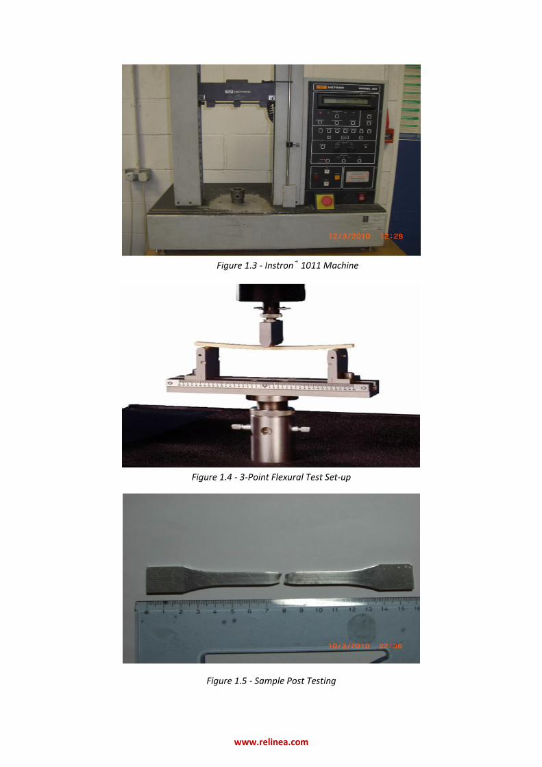
Flexural tests The 3-point flexure tests were carried out on the Instron® 1011 machine – Figure 1.3. Test were carried out in accordance with standard BS EN 2746-1998, “glass fibre reinforced plastics flexural test, 3-point bending method” .Two different hand lay-up GRP composites where tested. The first test was of a composite with glass fibre diameters of 600μm and the second test was of 450μm glass fibre diameters. Eight specimens of each material were tested and all were tested to failure. Specimens were simply supported via horizontal clamps and a point load was used to apply the force in the vertical direction to the mid-section of the specimen. Figure 1.4 shows a similar apparatus set up to that of the tests carried out in this project.
www.relinea.com
Figure 1.3 - Instron® 1011 Machine
Figure 1.4 - 3-Point Flexural Test Set-up
Figure 1.5 - Sample Post Testing

www.relinea.com
Results:
Figure 1.6 – Tensile Strength
Figure 1.7 – % Strain @ Break- GRP
Figure 1.8 – % Strain @ Break - Steel & Aluminium

www.relinea.com
Figure 1.9 – Young’s Modulus
Figure 1.10 – Flexural Modulus
Table 1.1 Densities of Materials Used
Material Density kg/m³
GRP 1676
Aluminium 2700
Steel 8000

www.relinea.com
Figure 1.11 – Specific Strength
Discussions:
In comparing the mechanical properties of GRP materials to aluminium and steel it is clear that the metals have the advantage. Modulus and % strain at break both favour the metallic alternatives. However when considering the UTS of the different materials is can be seen that aluminium exhibits a lower value than that of the pultruded specimens. It can also been seen that the UTS of the pultruded specimens (472.38MPa) contends greatly with the stainless steel 304 UTS (658.4MPa). The UTS of the common grade aluminium (123.6MPa) is similar to that of the hand lay-up GRP components (108.9 – 147.33MPa). This shows the potential these easily produced hand lay-up composites have as replacements to structural aluminium. Looking at the specific weights, we can see that GRP composites far exceed the capabilities of aluminium and steel in this regard. Table 1.1 shows the approx. densities of GRP, steel and aluminium. It can be seen that GRP is approximately 80% less dense than the stainless steel 304 and approximately 48% less dense than aluminium. The specific strength histogram – Figure 1.11 – shows the pultruded specimens to exhibit the most favourable strength to weight ratios greatly exceeding the steel and aluminium values at 281kNm/kg. In the instances where the GRP was formed from the process of hand lay-up it generally exhibited ratios, similar to that of the stainless steel, and greater to that of the aluminium.
Conclusions:
While the overall strength, modulus and percentage strain characteristics are dominated by the stainless steel 304, the specific strength of the GRP specimens are of equal, or in the pultruded specimens case greater, equivalence to the steel and aluminium strength to weight ratios. It has also been found that the overall tensile strength of aluminium can be matched by the hand lay-up GRP specimens and surpassed by the pultruded specimens.
www.relinea.com
2. Ladder Acceptance Testing
Location:
Parson’s Building: Mechanical & Manufacturing Engineering, Trinity College Dublin, Dublin 2, Ireland
4.
Date of Testing:
17th May 2010
5.
Test Undertaken by:
Mr. Michael O’Riordan, Mr. Anthony Maguire and Mr. Paul Brennan
6.
Test Background and Procedure:
The Ladder Acceptance Test was performed to the specifications as detailed in the NFPA 1932 Chapter 7 Service Testing of Ground Ladders – the American Fire Departments Standard for testing their ladders. The ladder to be tested was Requirements of the test:
1. The ladder shall be placed in a flat horizontal position and supported 150 mm (6 in.) from each end of the ladder.
2. The supports shall be high enough that the ladder does not touch the floor or other surface during the test.
3. The ladder shall not be tied, strapped, or otherwise fastened to the supports. 4. The ladder shall be loaded with a preload of 159 kg that shall remain in place for at least 1
minute to “set” the ladder prior to the completion of the rest of the test. 5. The preload shall be removed, and the distance between the bottom edge of each beam and
the surface upon which the ladder supports are placed shall be measured at the lengthwise centre of the ladder.
6. The ladder shall be loaded with a test load of 227 kg that shall remain in place for 5 minutes. 7. The test load shall then be removed and the ladder be allowed to rest for 5 minutes. 8. The distance between the bottom of each beam and the surface upon which the ladder
supports are placed shall be measured at the same spot that the measurements were taken in step 5.
9. Differences in measurements taken in step 8 and step 5 shall not exceed the following values
Table 2.1: Allow Differences in Horizontal Bending Test Recovery
Ranges Allow Differences in Horizontal Bending Test Recovery
<7.6 ” 18-25” 12.7mm
7.7–10.4” 26–34” 25.4mm
10.5-18” >35” 38.1mm
www.relinea.com
10. There shall be no visible permanent change or failure of any hardware. Any ladder that exceeds the allowable difference in horizontal bending test recovery, has visible permanent change, or has failure of any hardware shall be removed from service.
Results:
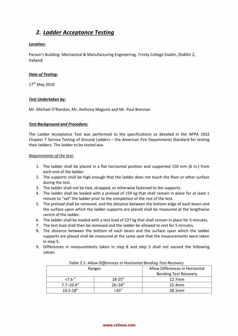
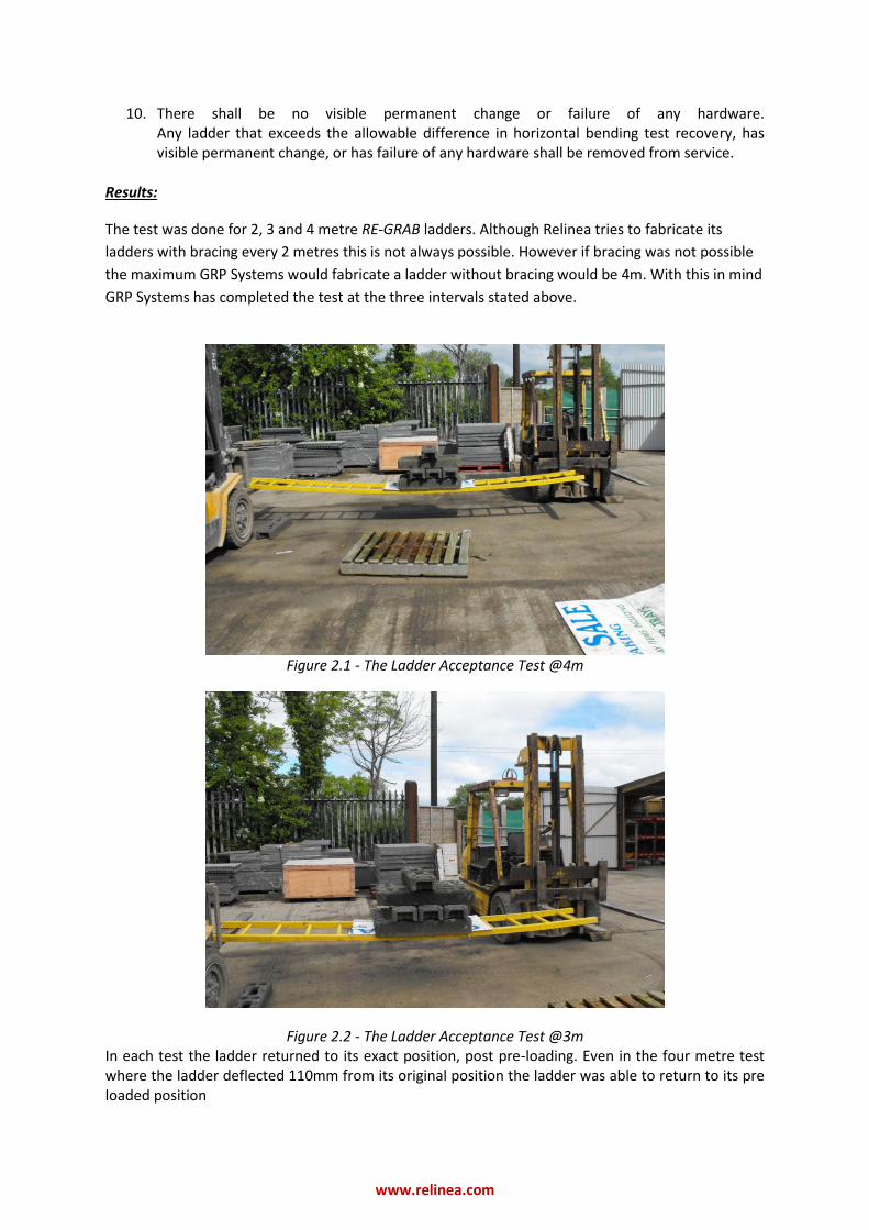
The test was done for 2, 3 and 4 metre RE-GRAB ladders. Although Relinea tries to fabricate its
ladders with bracing every 2 metres this is not always possible. However if bracing was not possible
the maximum GRP Systems would fabricate a ladder without bracing would be 4m. With this in mind
GRP Systems has completed the test at the three intervals stated above.
Figure 2.1 - The Ladder Acceptance Test @4m
Figure 2.2 - The Ladder Acceptance Test @3m In each test the ladder returned to its exact position, post pre-loading. Even in the four metre test where the ladder deflected 110mm from its original position the ladder was able to return to its pre loaded position

www.relinea.com
Following on from this it can be considered that the GRPGrab Ladder easily passed the criterion as established by the NFPA 1932: Chapter 7 Service Testing of Ground Ladders.
Conclusions:
The GRPGrab Ladder was found to easily pass the criterion as established by the ladder NFPA 1932: Chapter 7 Service Testing of Ground Ladders.

www.relinea.com
3. Handrail Acceptance Testing
Location:
Parson’s Building: Mechanical & Manufacturing Engineering, Trinity College Dublin, Dublin 2, Ireland
4.
Date of Testing:
12th October 2009
5.
Test Undertaken by:
Dr. Biqiong Chen, Mr. William Collins, Mr Peter O’Reilly and Mr. Michael O’Riordan
6.
Test Background and Procedure:
A number of samples were made up which replicated all the samples required to complete the ICC-AC273 (Acceptance Criteria for Handrails and Guards) test by Relinea. To perform the test, an Instron® 8801 machine was used to perform the loading.
The Tests: In-fill Load Test: The test specimen shall have the infill (i.e. the mid-rail) tested, and shall be capable of satisfactorily resisting a load of 556N applied over a 0.09293 m2 area normal to the in-fill. The guardrail system is considered to pass if there is no failure, nor evidence of disengagement of any component, nor visible cracks in any component. Uniform Load Test: The top rail of the guard and handrail test specimens shall be subjected to a individual tests where a maximum uniform load of 1.82kN/m is applied vertically and then in an outward direction normal to the horizontal. The guardrail system is considered to pass if there is no failure, nor evidence of disengagement of any component, nor visible cracks in any component. Concentrated Load Test: Two separate tests on each specimen shall be conducted, where a test load of 2.22kN is applied at the mid-span of the top rail and at the top of a single post in an outward direction. In both cases, the load shall be continuously applied horizontally and normal to the top rail at the maximum guard and handrail system height. When the applied load reaches 0.89kN, the deflection at the point of loading shall be recorded. The allowable deflection for the system at 0.890kN shall not exceed either one of the following allowable deflection limits:
a) height/24 + length/96. Where the effective rail length is the distance between the edges of the posts, the deflection at the mid-span of the top rail (guard) is measured relative to the centre of the two posts (i.e., it does not include post deflection).
b) height/12, where the effective newel post height, is the distance from the top of the top rail, to the first point of fastener connection to the supporting construction.
Additionally, the mounting of handrails shall be such that the completed handrail and supporting structure are capable of withstanding a load of at least 2.22kN when determined by tests.
www.relinea.com
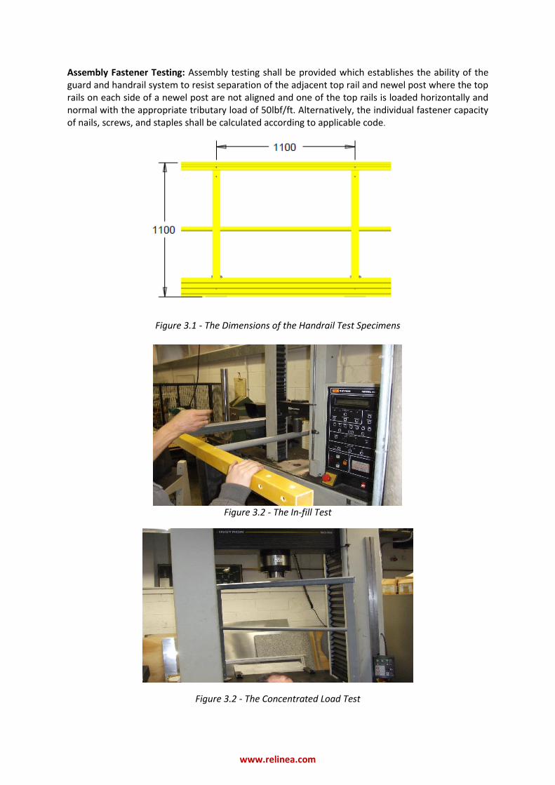
Assembly Fastener Testing: Assembly testing shall be provided which establishes the ability of the guard and handrail system to resist separation of the adjacent top rail and newel post where the top rails on each side of a newel post are not aligned and one of the top rails is loaded horizontally and normal with the appropriate tributary load of 50lbf/ft. Alternatively, the individual fastener capacity of nails, screws, and staples shall be calculated according to applicable code.
Figure 3.1 - The Dimensions of the Handrail Test Specimens
Figure 3.2 - The In-fill Test
Figure 3.2 - The Concentrated Load Test

www.relinea.com
Results: In-fill Load Test: The test specimen easily passed the criteria as set out by the ICC-AC273 document. Uniform Load Test: The test specimen easily passed the criteria as set out by the ICC-AC273 document. Concentrated Load Test: The test specimen easily passed the criteria as set out by the ICC-AC273 document. When loaded to 2.22kN the handrail and supporting structure were easily capable of withstanding the load as determined by the tests.
a.) @ 0.89kN the Top rail was seen to deflect 44mm. Max allowable = 56mm. b.) @ 0.89kN the Top rail was seen to deflect 44mm. Max allowable = 92mm.
Assembly Fastener Testing: The test specimen easily passed the criteria as set out by the ICC-AC273 document. Also, all rivets used by Relinea can resist a minimum axial load of 6.4kN as well as being able to resist a pull-load force of 5.1kN. NB** Another test: the Newel Base Load Performance Test is comprised in the ICC-AC273 document; however it was not possible to test for this with the machinery available at TCD.
Conclusions:
The RE-GRAB Handrail easily performed to the testing requirements (of which it was capable of testing to with the machinery in TCD) as detailed in the ICC-AC273 document.

www.relinea.com
4. Impact Resistance of Grating
Location:
Simon Perry Building: Civil & Structural Engineering, Trinity College Dublin, Dublin 2, Ireland
Date of Testing:
15th March 2010
Test Undertaken by:
Dr. Roger West, Mr. Barrie McElhinney and Mr. Michael O’Riordan
Test Background and Procedure:
A number of identically dimensioned test samples were made from GRP (RE-GRID3838 Open Mesh
Grating) and steel (Flowforge Open Grating) and tested for the impact resistance capabilities using a
drop test rig in the Civil & Structural Engineering Department in TCD. Although RE-GRID3838 and
Flowforge are not identical – Flowforge Open Grating is a steel, and therefore the connecting beams
need to be welded together and therefore the cross-sections are much different, Flowforge was
decided to be tested against Relinea’s RE-GRID3838 Open Mesh Grating as they are both used for
the same function. Figures 4.1 and 4.2, shows the inherent differences between the two grating
types. Figure 4.3 on the other hand shows applications where the Flowforge Open Grating systems
have previously been used.
Regarding the test, a 76kg steel billet was released from rest from a number of different heights
onto both sample types – as shown in Figure 4.4. The test rig does not conform to any standard;
however the test was very useful in showing the differences in the elastic properties between the
two material types. The rig had a minimum set-up height of 0.62m and a maximum set-up height
of 2.75m. Each sample had a dimension of 550x400x38mm.
Figure 4.1 – RE-GRID3838 Open Mesh Grating
www.relinea.com
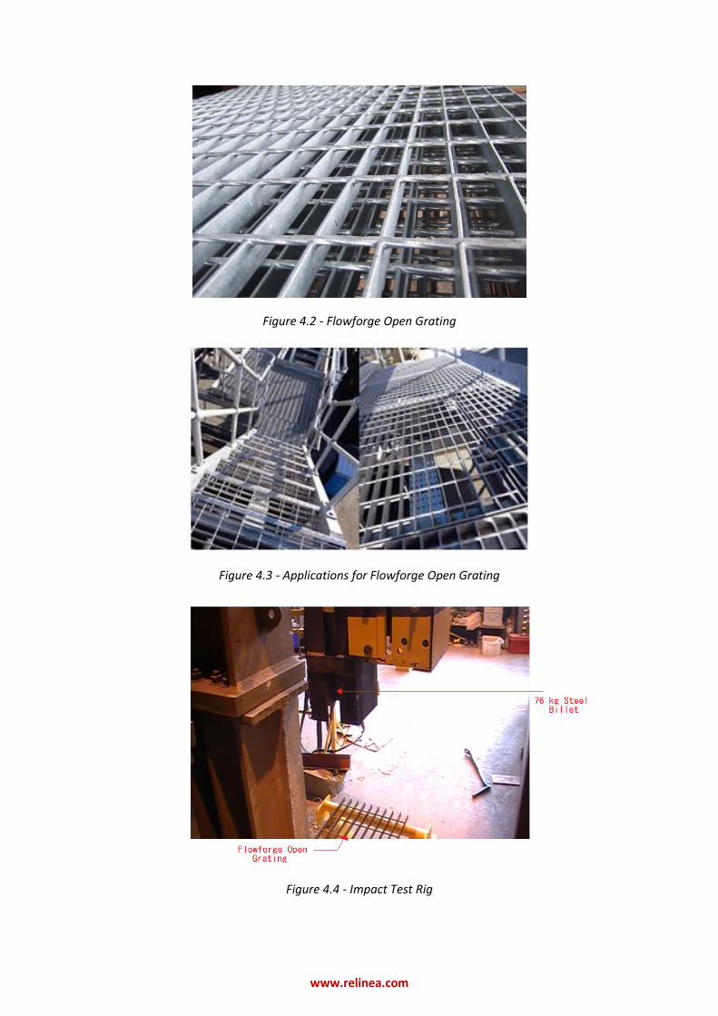
Figure 4.2 - Flowforge Open Grating
Figure 4.3 - Applications for Flowforge Open Grating
Figure 4.4 - Impact Test Rig

www.relinea.com
Results:
Flowforge Open Grating
As can be seen from Figure 4.5 –the result of the test in Figure 4.4 where the test was undertaken at
the minimum height of 0.62m - i.e. approximately a 5kN Force - the Flowforge panel was completely
elastically deformed due the force of the billet. The force of the billet can be measured from the
equation F = mgh. The steel plate absorbed all the force of the billet, but was not able to dissipate a
sufficient amount of the energy to prevent elastic deformation, and hence this phenomenon was
observed on the Flowforge Open Grating Panel on each test.
Figure 4.5 - Flowforge Open Grating after Impact from the 76kg billet @ h=0.62m
The GRP RE-GRID
On the other hand, all of the GRP RE-GRID test specimens were able to absorb all the energy of the billet in all of the tests criteria - even up to a height of 2.75m: the equivalent of a 20kN Force. In repeated testing of the same GRP samples; the fibres of that particular sample would eventually split and the panel would eventually split in two. This however never happened in the first one-three tests and would only happen occur after the 4th or 5th impact of the same sample. The Flowforge samples on the other hand failed first time, every time.
Flowforge @ 0.62m.MOD GRP @ 2.75m.MOD
Conclusions:
Steel - i.e. Flowforge Open Grating – exhibits very poor impact resistance properties. GRP however exhibits excellent initial impact resistance properties; only failing after multiple testing of the same specimen

www.relinea.com
5. Fire Resistance of Grating
Location:
FireSERT, University of Ulster, Newtownabbey, County Antrim, Northern Ireland, BT37 9QB
Date of Testing:
15th October 2009.
Test Undertaken by:
Dr. Michael Delichatsios and Mr. Noel McCutcheon
Test Background and Procedure:
A test sample – as shown in Figure 5.1 - was made by Relinea. The test sample was made up of a
2000x2000mm unprotected steel frame which had an I–beam running through the centre. 2 No. RE-
DECK384 panels were then placed on top of the structure and affixed using Dow Corning® FIRESTOP
700 Silicone Sealant and standard M8 CSK bolts with W-clips.
This test sample was then brought to the University where it was tested to failure. The test
comprised of placing the sample on top of a furnace – as shown in Figure 5.2 -; strategically placing
load cells (which act as thermometers) on the top surface of the sample –as shown in Figure 5.3 -
and then testing the rig until failure.
Failure was deemed to have occurred when one of the following occurs:
a) If the mean unexposed face temperature increases by more than 140 o
C above its initial value;
b) If the temperature recorded at any position on the unexposed face, either by a fixed
thermocouple or the roving thermocouple is in excess of 180o
C above the initial mean unexposed face temperature;
c) When integrity / impermeability failures as defined below occur. i) When sustained flaming or collapse of the unexposed face occurs; ii) When flames & or hot gases cause flaming or glowing of the cotton fibre pad; iii) The 6 mm diameter gap gauge can penetrate a through gap such that the end of the
gauge projects into the furnace and the gauge can be moved in the gap for a distance of at least 150 mm; or the 25 mm gap gauge can penetrate a through gap such that the end of the gauge projects into the furnace.
These are the failure requirements of this test according to The British Standard BS 476 20 / 22.
As such, the test was carried out in accordance with this criterion.

www.relinea.com
Figure 5.1 - Fire Resistance Test Rig
Figure 5.2 - Fire Resistance Test Rig on Top of Furnace
Figure 5.3 - Load Cell Placement Diagram

www.relinea.com
Results:
The test heating period was terminated after a period of 41 minutes of heating had elapsed and the main observations were noted. Table 5.1 summarises the test data obtained.
Table 5.1 - Observation of the Fire Resistance Test
Time into Test Key Test Observation
0 minutes Pre test: Laboratory ambient temperature recorded as 16°C
3 minutes Smoke from the LHS panel (A) of the test specimen
9.5 minutes Exposed face inside the furnace on fire
13 minutes Over (140 + 16) degrees Celsius measured on the unexposed face of the (LHS) panel A.
Smoke coming from a small pin hole on RHS panel (B). Cotton pad test ok.
15 minutes Over (140 + 16) degrees Celsius measured on the unexposed face of the both the RHS (B) and LHS panel (A).
19 minutes Deflection reduced and slight bowing of panels now observed
28 minutes Smoke from the small pin hole on the RHS panel (B) slightly browned cotton pad. Cotton pad test ok.
35 minutes Gap opening up around the length of the joint between the RHS (B) and LHS (A) panels.
41 minutes Test was terminated after a period of 41 minutes: due to sustained flaming breaking out and through on the unexposed face at the mid joint
over the central beam between the RHS (B) and LHS (A) panels.
Test Results Summary Integrity: 41 Minutes Test terminated after 41 minutes owing to the occurrence of sustained flaming on the unexposed face
5mm Panel A: Insulation: 13 Minutes Unexposed mean-face-temperature greater than (140 + 16) o
C.
5mm Panel A: Deflection: 8mm @ the mid span point of the 5mm thick plated 2m by 1m panel A
3mm Panel B: Insulation: 15 Minutes Unexposed mean-face-temperature greater than (140 + 16) o
C.
3mm Panel B: Deflection: 6mm @ the mid span point of the 3mm thick plated 2m by 1m panel B
Results Statement “The results only relate to the behaviour of the specimen of the element of construction under the particular conditions of the test; they are not intended to be the sole criteria for accessing the potential fire performance of the element in use nor do they reflect the actual behaviour in fires”. Conclusions
The integrity of the panels failed due to fire breaking through, with sustained flaming breaking out on the unexposed face of the test specimen at the central joint of the two floor panels across the top of the central unprotected steel I beam support where both floor panels A & B were butt jointed. However this only occurred after 41 mins. The unexposed face of the test sample had a mean temperature less than (140 + 16) °C for 13 minutes. This meant the panels were safe for operation to their minimal standard, for at least 12 minutes. A standard fire door has a safe operational time of 30 minutes.

www.relinea.com
6. Anti-Slip Testing
Location:
Highway Engineering Research Group, University of Ulster, Newtownabbey, County Antrim, Northern Ireland, BT37 9QB
Date of Testing:
19th October 2009.
Test Undertaken by:
Dr. David Woodward and Mr. Ian Martin
Test Background and Procedure:
Four specimens of anti-slip flooring, each bonded with different types of grit - Grit 14, Grit 16, Grit
20 and Grit 40 - were assessed for their dry and wet slip resistance properties using a pendulum test
rig (as specified in BS 7976-2). TRL rubber and 4S rubber were used to on the pendulum test rig to
measure the dry and wet slip resistance properties of the flooring samples.
Figure 6.1 shows the pendulum test rig. The operator presses the switch as shown in the diagram
and the pendulum is released. The rate at which the pendulum slows down is directly proportional
to the slip resistance of the plate and this is how we can measure the slip resistance.
Figure 6.1 - Pendulum Test Rig
www.relinea.com
Results:
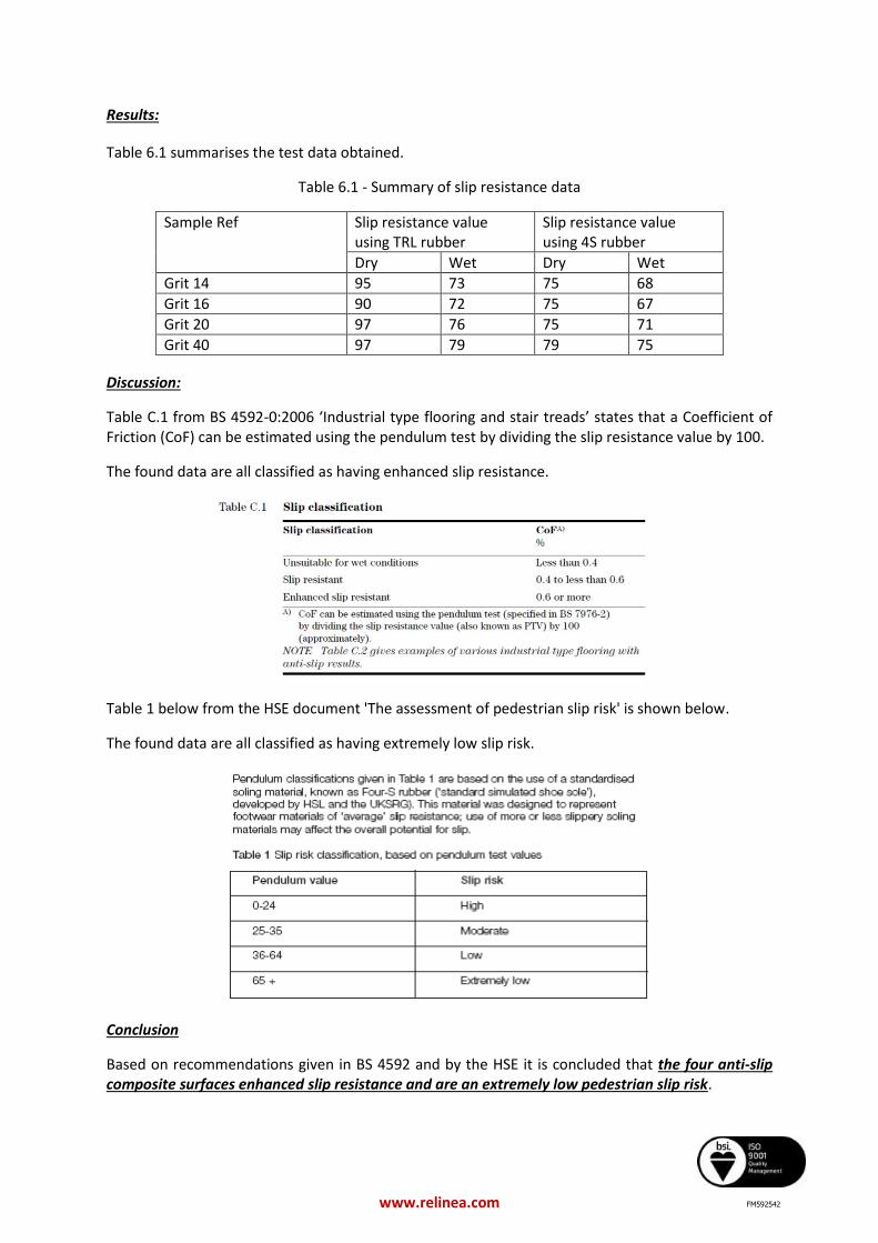
Table 6.1 summarises the test data obtained.
Table 6.1 - Summary of slip resistance data
Sample Ref Slip resistance value using TRL rubber
Slip resistance value using 4S rubber
Dry Wet Dry Wet
Grit 14 95 73 75 68
Grit 16 90 72 75 67
Grit 20 97 76 75 71
Grit 40 97 79 79 75
Discussion:
Table C.1 from BS 4592-0:2006 ‘Industrial type flooring and stair treads’ states that a Coefficient of Friction (CoF) can be estimated using the pendulum test by dividing the slip resistance value by 100.
The found data are all classified as having enhanced slip resistance.
Table 1 below from the HSE document 'The assessment of pedestrian slip risk' is shown below.
The found data are all classified as having extremely low slip risk.
Conclusion
Based on recommendations given in BS 4592 and by the HSE it is concluded that the four anti-slip composite surfaces enhanced slip resistance and are an extremely low pedestrian slip risk.
FM592542