test cameras and connections prior to mounting. · be entered to win a $100 gift card! remote...
TRANSCRIPT

FRE
ED
OMquick-start
QT SERIES HD NVRS
GUIDE
15 13 11 9 7 5 3 1
ALARM OUT
ALARM IN GN
DG
ND
CO
M
NO VGA LANHDMI CVBS USB 1 3 5
2 4 6RS485K/BA B
16 14 12 10 8 6 4 2
OPTIONA
OPTIONB
OR
VGA
19”+
OPTIONA
OPTIONB15 13 11 9 7 5 3 1
ALARM OUT
ALARM IN GN
DG
ND
CO
M
NO VGA LANHDMI CVBS USB 1 3 5
2 4 6RS485K/BA B
16 14 12 10 8 6 4 2
OPTIONA
OPTIONB
OR
VGA
19”+
OPTIONA
OPTIONB
Choose video display option A or B:
STEP 2 CONNECT TO VIDEO DISPLAY
OPTION AHDMI
A. Plug the included HDMI cable into the NVR’s HDMI port.
B. Connect the other end of the HDMI cable to the monitor or TV.
C. Plug the monitor or TV into a surge protector.
OPTION BVGA MONITOR
A. Plug a VGA cable (not included) into the NVR’s VGA port.
B. Connect the other end of the VGA cable to the monitor.
C. Plug the monitor into a surge protector.
NOTE: The monitor must me 19” or larger
NOTE: This is the highest quality viewing option
15 13 11 9 7 5 3 1
ALARM OUT
ALARM IN GN
DG
ND
CO
M
NO VGA LANHDMI CVBS USB 1 3 5 7
2 4 6 8RS485K/BA B
16 14 12 10 8 6 4 2
IP CAMERA
EXTENSION CABLE
VIDEO IN POE PORTS
Test cameras and connections prior to mounting. If specialty camera(s), such as a PTZ, are included in your package, please review instructions for specialty camera(s) before proceeding to Step 1.
Plug the CAT5E Extension Cable into the camera’s network port.
NOTE: Your NVR model may differ from that shown in this illustration.
A B CPlug the other end of the Extension Cable into one of the POE ports on the back of the NVR.
Repeat steps A & B for each camera.
STEP 1 CONNECT YOUR CAMERAS
To add remote cameras to your NVR, see the end of this guide.
When doing final installation, connect your cameras one at a time. The NVR will assign cameras a channel in the order that they are connected.
STEP 5 TURN ON NVR
15 13 11 9 7 5 3 1
ALARM OUT
ALARM IN GN
DG
ND
CO
M
NO VGA LANHDMI CVBS USB 1 3 5 7
2 4 6 8RS485K/BA B
16 14 12 10 8 6 4 2
15 13 11 9 7 5 3 1
ALARM OUT
ALARM IN GN
DG
ND
CO
M
NO VGA LANHDMI CVBS USB 1 3 5 7
2 4 6 8RS485K/BA B
16 14 12 10 8 6 4 2
RJ45 EthernetCable
STEP 3 CONNECT TO ROUTERA. Plug the included Network (Ethernet) cable into
the Network port 3 on the back of the NVR.
B. Connect the other end of the cable to an open port on your router (not included).
Before starting the NVR, download the free QC View App (for mobile phones) or QC View HD App (for tablets) from your device’s app store.
A. Plug the NVR power adapter into the power port on the back of the NVR.
B. Plug the power cable into a surge protector.
C. Turn on the NVR’s power switch.
The NVR will beep as it powers up.
NOTE: Your NVR model may differ from that shown in this illustration.
A
B
Plug the mouse into the USB port 4 on the back of the NVR.
NOTE: The USB port on the front of the NVR is used for backing up video files.
STEP 4 CONNECT MOUSE
STEP3
STEP4
The Start Up Wizard will appear on-screen after a few minutes.
A B
QT1
1
IP Cameras can connect to an NVR with a network or Internet connection.STEP 8 REGISTER YOUR PRODUCT
LOCAL NETWORK
OVER THE INTERNET
Your feedback helps us build better products!Rate your product at http://q-see.com
Be entered to WIN a $100 gift card!
REMOTE CAMERAS
NetworkPort POE Injectors
11 2 3 4
PWR
2 3 4 UPLINK
UPLINK
You will need:• A network port that is connected to a router. • A POE Injector, such as Q-See’s QAPE401.• A CAT5 network cable (to connect injector and
network port).
If your camera and NVR will be in the same building, they can use the same local network to communicate with each other.
1. Plug the POE Injector into a power outlet. It is recommended that you use a UL-1449 rated surge protector to protect your equipment.
2. Using a CAT5 network cable, connect the data port on the POE Injector to a network port that is connected to an active network (connected to a router).
3. Use the included power/video cable to connect a camera to one of the POE ports. 4. On your NVR:
a. Select IP Camera from the Main Menu. b. Click on Search at the bottom of the Device
Manager window.c. Select one or more cameras from the list by
checking the box to its left.d. Click OK to return to the Device Manager window.e. Select a camera and click Setup.f. Check the Enable box and click OK.Repeat e-f for other cameras, if neededg. Click Apply to save before exiting window.
Your NVR can record video from an IP camera with an Internet connection.
Follow steps 1-3, above before proceeding with the instructions, below:1. Download and install either IP Tool (PC) or Smart PSS (Mac and PC) along with the
IP Camera manual from www.Q-See.com/Support.2. Obtain the camera’s IP address following the instructions in the manual. 3. On your NVR:
a. Select IP Camera from the Main Menu. b. Click on Search at the bottom of the Device Manager window.c. Enter the camera’s IP address, Server Port (85), User Name (admin) and password
(123456). You can change these using the software you downloaded.d. Check the Enable box and click OK.e. Click Apply to save before exiting window.
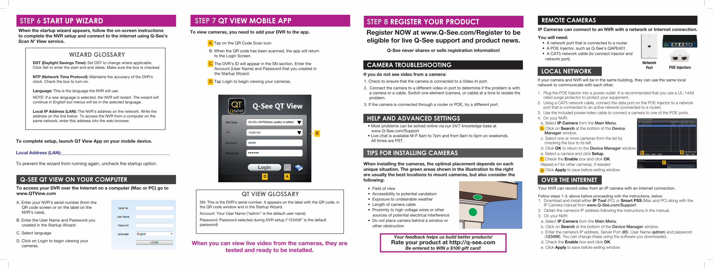
A. Tap on the QR Code Scan icon
B. When the QR code has been scanned, the app will return to the Login Screen.
C. The DVR’s ID will appear in the SN section. Enter the Account (User Name) and Password that you created in the Startup Wizard.
D. Tap Login to begin viewing your cameras.
STEP 6 START UP WIZARD STEP 7 QT VIEW MOBILE APP
WIZARD GLOSSARYDST (Daylight Savings Time): Set DST to change where applicable. Click Set to enter the start and end dates. Make sure the box is checked.
NTP (Network Time Protocol): Maintains the accuracy of the DVR’s clock. Check the box to turn on.
Language: This is the language the NVR will use.
NOTE: If a new language is selected, the NVR will restart. The wizard will continue in English but menus will be in the selected language.
Local IP Address (LAN): The NVR’s address on the network. Write the address on the line below. To access the NVR from a computer on the same network, enter this address into the web browser.
To complete setup, launch QT View App on your mobile device.
Local Address (LAN):____________________________________________
To prevent the wizard from running again, uncheck the startup option.
To access your DVR over the Internet on a computer (Mac or PC) go to www.QTView.com
Q-SEE QT VIEW ON YOUR COMPUTER
A. Enter your NVR’s serial number (from the QR code screen or on the label on the NVR’s case).
B. Enter the User Name and Password you created in the Startup Wizard
C. Select language
D. Click on Login to begin viewing your cameras.
To view cameras, you need to add your DVR to the app.
QT VIEW GLOSSARYSN: This is the DVR’s serial number. It appears on the label with the QR code, in the QR code window and in the Startup Wizard.
Account: Your User Name (“admin” is the default user name)
Password: Password selected during DVR setup (“123456” is the default password)
AD
C
SearchSearchDeleteDeleteSetupSetupAddAdd ApplyApply ExitExit
DEVICE MANAGEMENTDEVICE MANAGEMENT
CHCH Device Net Address Manufacturer StatusProduct ModelManufacturer StatusProduct ModelDevice Net Address
1/11/1
1 10.151.151.100 Q-See 9322M_ONVIF Connected
None 192.158.0.140 ONVIF ONVIF Disable
1 10.151.151.100 Q-See 9322M_ONVIF Connected
None 192.158.0.140 ONVIF ONVIF Disable
b
f
g
• Most problems can be solved online via our 24/7 knowledge base at www.Q-See.com/Support
• Live chat is available M-F 6am to 7pm and from 9am to 5pm on weekends. All times are PST.
HELP AND ADVANCED SETTINGS
CAMERA TROUBLESHOOTING
When installing the cameras, the optimal placement depends on each unique situation. The green areas shown in the illustration to the right are usually the best locations to mount cameras, but also consider the following:
• Field of view • Accessibility to potential vandalism• Exposure to undesirable weather• Length of camera cable• Proximity to high voltage wires or other
sources of potential electrical interference• Do not place camera behind a window or
other obstruction
TIPS FOR INSTALLING CAMERAS
If you do not see video from a camera:
1. Check to ensure that the camera is connected to a Video-In port.
2. Connect the camera to a different video-in port to determine if the problem is with a camera or a cable. Switch one element (camera, or cable) at a time to isolate the problem.
3. If the camera is connected through a router or POE, try a different port.
Register NOW at www.Q-See.com/Register to be eligible for live Q-See support and product news.
Q-See never shares or sells registration information!
When you can view live video from the cameras, they are tested and ready to be installed.
When the startup wizard appears, follow the on-screen instructions to complete the NVR setup and connect to the internet using Q-See’s Scan N’ View service.