terrestrial microwave antenna system products - رایتل · pdf fileterrestrial microwave...
TRANSCRIPT
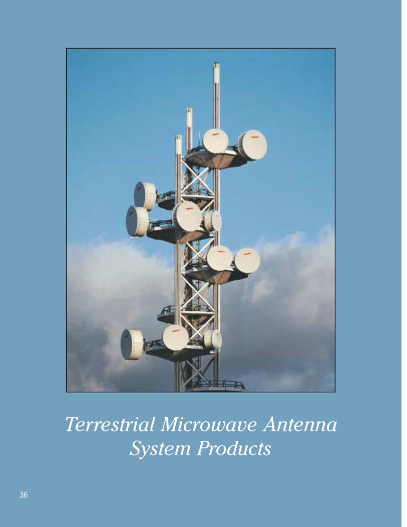
Terrestrial Microwave Antenna System Products
36

37
IndexTerrestrial Microwave Antennas
Terrestrial Microwave Antenna Nomenclature . . . . . . . . . . . . . . . . . . . . . . . . . 38Antenna Types . . . . . . . . . . . . . . . . . . . . . . . . . . . . . . . . . . . . . . . . . . . . . . . . . 39System Planning Software . . . . . . . . . . . . . . . . . . . . . . . . . . . . . . . . . . . . . . . . 44Antenna Construction . . . . . . . . . . . . . . . . . . . . . . . . . . . . . . . . . . . . . . . . . . . . 45Antenna Selection Criteria . . . . . . . . . . . . . . . . . . . . . . . . . . . . . . . . . . . . . . . . 47Electrical Specifications . . . . . . . . . . . . . . . . . . . . . . . . . . . . . . . . . . . . . . . . . . 48
Radiation Pattern Envelopes . . . . . . . . . . . . . . . . . . . . . . . . . . . . . . . . . . . . . 48Electrical Definitions . . . . . . . . . . . . . . . . . . . . . . . . . . . . . . . . . . . . . . . . . . . 49
Antenna Environmental Ratings . . . . . . . . . . . . . . . . . . . . . . . . . . . . . . . . . . . . 49Antenna Specifications and Ordering Information. . . . . . . . . . . . . . . . . . . . . . . 50
Ordering Tables by Frequency Band . . . . . . . . . . . . . . . . . . . . . . . . . . . . . . . 51Multiband Antennas . . . . . . . . . . . . . . . . . . . . . . . . . . . . . . . . . . . . . . . . . . . 92
Mechanical Specifications . . . . . . . . . . . . . . . . . . . . . . . . . . . . . . . . . . . . . . . . 95Forces Produced by Microwave Antennas . . . . . . . . . . . . . . . . . . . . . . . . . . . . 111Antenna Options . . . . . . . . . . . . . . . . . . . . . . . . . . . . . . . . . . . . . . . . . . . . . . . 114Antenna Accessories. . . . . . . . . . . . . . . . . . . . . . . . . . . . . . . . . . . . . . . . . . . . 123
ValuLine® Antennas
Introduction . . . . . . . . . . . . . . . . . . . . . . . . . . . . . . . . . . . . . . . . . . . . . . . . . . 127ValuLine Antenna Nomenclature. . . . . . . . . . . . . . . . . . . . . . . . . . . . . . . . . . . 128Antenna Specifications and Ordering Information . . . . . . . . . . . . . . . . . . . . . . 130
Ordering Tables by Frequency Band . . . . . . . . . . . . . . . . . . . . . . . . . . . . . . 131Mechanical Specifications . . . . . . . . . . . . . . . . . . . . . . . . . . . . . . . . . . . . . . . 138Forces and Twisting Moments Due to Wind Loads . . . . . . . . . . . . . . . . . . . . . 148Antenna Packing . . . . . . . . . . . . . . . . . . . . . . . . . . . . . . . . . . . . . . . . . . . . . . . 149
Microwave Transmission Line
Transmission Line Selection . . . . . . . . . . . . . . . . . . . . . . . . . . . . . . . . . . . . . . 150HELIAX® Coaxial Cables 1427-2700 MHz . . . . . . . . . . . . . . . . . . . . . . . . . . . . 152HELIAX Elliptical Waveguide . . . . . . . . . . . . . . . . . . . . . . . . . . . . . . . . . . . . . 156Elliptical Waveguide Accessories . . . . . . . . . . . . . . . . . . . . . . . . . . . . . . . . . . 195
Hanger Spacing for Elliptical Waveguide . . . . . . . . . . . . . . . . . . . . . . . . . . . 196Hybrid T Reflectometer . . . . . . . . . . . . . . . . . . . . . . . . . . . . . . . . . . . . . . . . . . 201Rectangular Waveguide . . . . . . . . . . . . . . . . . . . . . . . . . . . . . . . . . . . . . . . . . 202
Flange Codes and Identification. . . . . . . . . . . . . . . . . . . . . . . . . . . . . . . . . . 204Elliptical Waveguide Components . . . . . . . . . . . . . . . . . . . . . . . . . . . . . . . . 207
Circular Waveguide . . . . . . . . . . . . . . . . . . . . . . . . . . . . . . . . . . . . . . . . . . . . 219Circular Waveguide Components. . . . . . . . . . . . . . . . . . . . . . . . . . . . . . . . . 220Circular Waveguide Accessories . . . . . . . . . . . . . . . . . . . . . . . . . . . . . . . . . 225
Technical Data . . . . . . . . . . . . . . . . . . . . . . . . . . . . . . . . . . . . . . . . . . . . . . . . 227Waveguide Attenuation Graphs . . . . . . . . . . . . . . . . . . . . . . . . . . . . . . . . . . 230

Customer Service Center - Call toll-free from: • U.S.A., Canada and Mexico 1-800-255-147938
Terrestrial Microwave Antenna Nomenclature
Andrew uses an alphanumeric numbering system foridentification and ordering of terrestrial microwave antennas. Andrew type numbers describe antenna type,size and operating frequency band. The system is knownworldwide, and many governments, PTTs and OEMs useAndrew terminology such as “HSX type performance” to specify antennas within their equipment procurementdocuments.
Example:
1 2 3 4 5HSX 10 - 59
PL 8 - 71 W
KP 6 F - 19
1. Antenna Type. The prefix is one, two, three or four letters that describe the antenna type. “X” within the prefix indicates dual-polarized operation.
For Standard Antennas, “L” indicates low VSWR antennas operating with:
Coaxial feed systems of 1.10 (26.4) RL or better
Waveguide feed systems of 1.06 (30.7) RL or better.
2. Antenna Size. The number indicates antenna diameter in feet.
3. Pressurization. Antennas having an “F” following the antenna size include a foam-dielectric feed and do not require pressurization. All other antennas have air-dielectric feeds and require pressurization. See pages 242-271 for pressurization equipment.
4. Frequency Band. The numbers following the hyphen are an abbreviated designation for the operating fre-quency band. For example:
Abbreviation Frequency Band
19 1.9 - 2.3 GHz
59 5.925 - 6.425 GHz
107 10.70 - 11.70
5. Wide band. A “W” following the frequency band designator indicates wide band operation for special applications. For example:
PL12-71 indicates the frequency band 7.125-7.750 GHzPL12-71W indicates the frequency band 7.100-8.500 GHz
Prefix Antenna Type or Description
KP_F, KPR_F Knockdown GRIDPAK® Parabolic
MKP Mini Knockdown GRIDPAK Parabolic
P, PX, P_F Standard Parabolic-Unshielded
PL, PL_F, PXL, PXL_F Standard Parabolic, Low VSWR-Unshielded
FP, FP_F, FPX Standard Focal Plane Parabolic-Unshielded
FPHP Focal Plane High Performance
HP, HP_F, HPX High Performance Parabolic-Shielded
HSX High Performance Super High CrossPolarization Discrimination-Parabolic
UHP, UHX, UHP_F Ultra High Performance Parabolic
UMX Ultra High Performance Multiband Parabolic
HDX, HDH, HDV High Performance Dual Beam-Parabolic
PDV, PDH Standard Dual Beam Angle Diversity
KPR Knockdown GRIDPAK Parabolic-Rural Telephony
PAR, PARX Parabolic Antenna for Relocation-Category A
LB, LBX Low Back Lobe
• U.K. 0800-250055 • Australia 1800-803 219 • New Zealand 0800-441-747 Visit us at: www.andrew.com 39
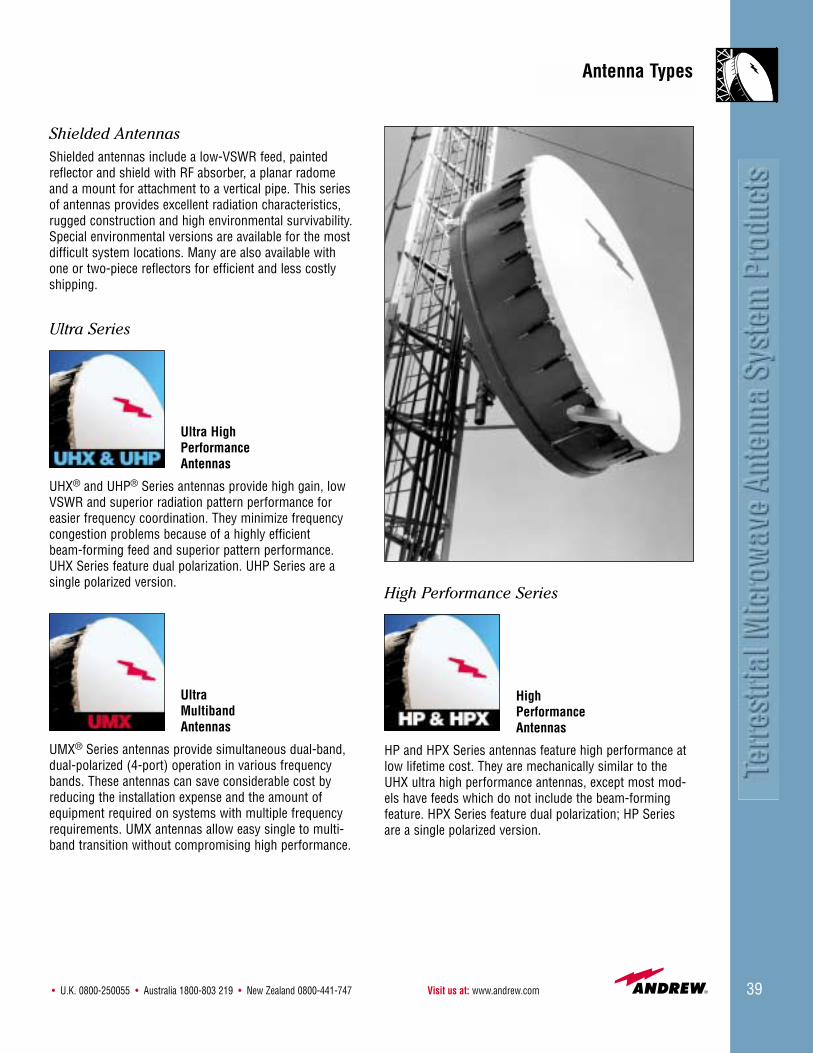
High Performance Series
High Performance Antennas
HP and HPX Series antennas feature high performance atlow lifetime cost. They are mechanically similar to theUHX ultra high performance antennas, except most mod-els have feeds which do not include the beam-forming feature. HPX Series feature dual polarization; HP Seriesare a single polarized version.
Shielded AntennasShielded antennas include a low-VSWR feed, paintedreflector and shield with RF absorber, a planar radomeand a mount for attachment to a vertical pipe. This seriesof antennas provides excellent radiation characteristics,rugged construction and high environmental survivability.Special environmental versions are available for the mostdifficult system locations. Many are also available withone or two-piece reflectors for efficient and less costlyshipping.
Ultra Series
Ultra High Performance Antennas
UHX® and UHP® Series antennas provide high gain, lowVSWR and superior radiation pattern performance foreasier frequency coordination. They minimize frequency congestion problems because of a highly efficient beam-forming feed and superior pattern performance.UHX Series feature dual polarization. UHP Series are asingle polarized version.
Ultra Multiband Antennas
UMX® Series antennas provide simultaneous dual-band, dual-polarized (4-port) operation in various frequencybands. These antennas can save considerable cost byreducing the installation expense and the amount ofequipment required on systems with multiple frequencyrequirements. UMX antennas allow easy single to multi-band transition without compromising high performance.
Antenna Types
Customer Service Center - Call toll-free from: • U.S.A., Canada and Mexico 1-800-255-147940
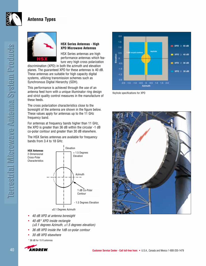
HSX Series Antennas - HighXPD Microwave Antennas
HSX Series antennas are highperformance antennas which fea-ture very high cross polarization
discrimination (XPD) in both the azimuth and elevationplanes. The guaranteed XPD for these antennas is 40 dB.These antennas are suitable for high capacity digital systems, utilizing transmission schemes such asSynchronous Digital Hierarchy (SDH).
This performance is achieved through the use of anantenna feed horn with a unique illuminator ring design and strict quality control measures in the manufacture ofthese feeds.
The cross polarization characteristics close to the boresight of the antenna are shown in the figure below.These values apply for antennas up to the 11 GHz frequency band.
For antennas at frequency bands higher than 11 GHz, the XPD is greater than 36 dB within the circular -1 dB co-polar contour and greater than 30 dB elsewhere.
The HSX Series antennas are available for frequencybands from 3.4 to 18 GHz.
Elevation
+ 1.5 DegreesElevation
Azimuth
- 1.5 Degrees Elevation
±0.1 Degrees Azimuth
HSX Antennas2-Dimensional Cross-Polar Characteristics
• 40 dB XPD at antenna boresight• 40 dB* XPD inside rectangle
(±0.1 degrees Azimuth, ±1.5 degrees elevation)• 36 dB XPD inside the 1dB co-polar contour• 30 dB XPD elsewhere* 36 dB for 15 ft antennas
Keyhole specifications for XPD
Antenna Types
1 dB Co-PolarContour
• U.K. 0800-250055 • Australia 1800-803 219 • New Zealand 0800-441-747 Visit us at: www.andrew.com 41
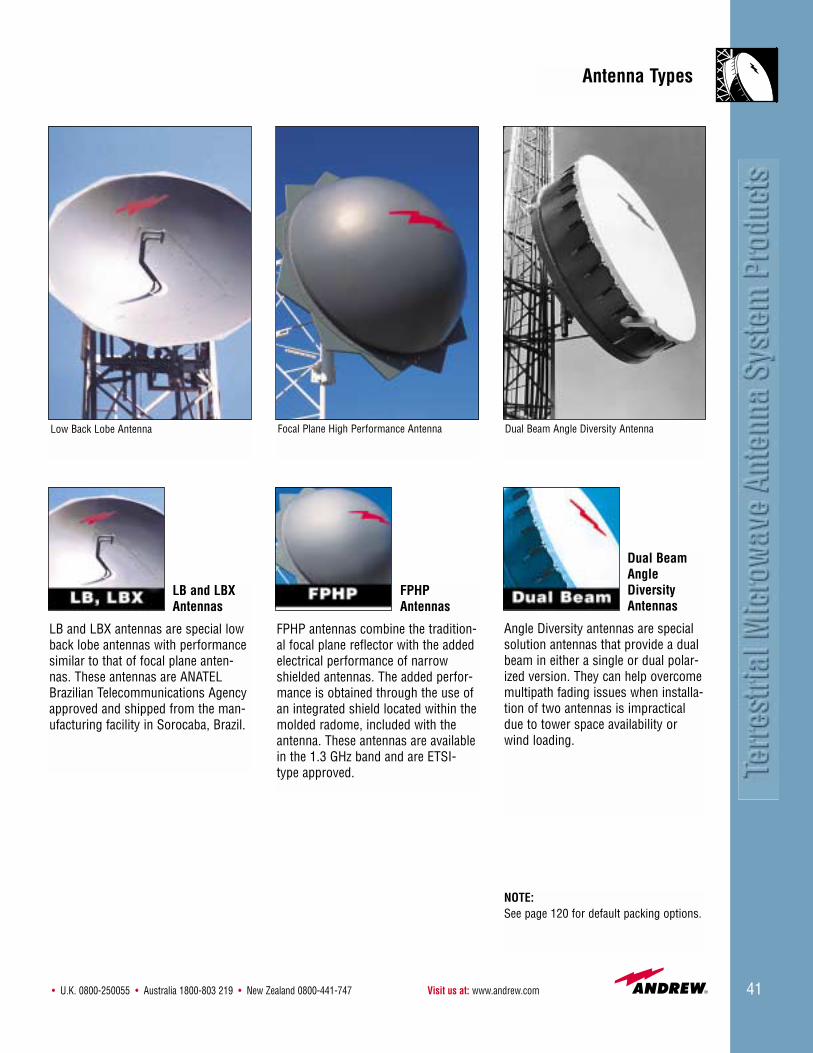
LB and LBXAntennas
LB and LBX antennas are special lowback lobe antennas with performancesimilar to that of focal plane anten-nas. These antennas are ANATELBrazilian Telecommunications Agencyapproved and shipped from the man-ufacturing facility in Sorocaba, Brazil.
FPHPAntennas
FPHP antennas combine the tradition-al focal plane reflector with the addedelectrical performance of narrowshielded antennas. The added perfor-mance is obtained through the use ofan integrated shield located within themolded radome, included with theantenna. These antennas are availablein the 1.3 GHz band and are ETSI-type approved.
Dual BeamAngleDiversityAntennas
Angle Diversity antennas are special solution antennas that provide a dualbeam in either a single or dual polar-ized version. They can help overcomemultipath fading issues when installa-tion of two antennas is impracticaldue to tower space availability orwind loading.
Antenna Types
NOTE:See page 120 for default packing options.
Low Back Lobe Antenna Focal Plane High Performance Antenna Dual Beam Angle Diversity Antenna
Customer Service Center - Call toll-free from: • U.S.A., Canada and Mexico 1-800-255-147942
Antenna Types
NOTE:See page 120 for default packing options.
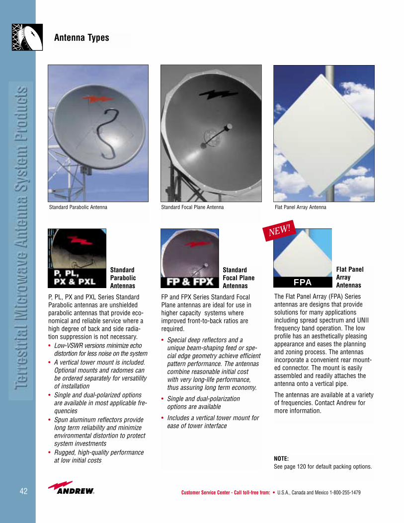
Standard Parabolic Antennas
P, PL, PX and PXL Series StandardParabolic antennas are unshieldedparabolic antennas that provide eco-nomical and reliable service where ahigh degree of back and side radia-tion suppression is not necessary. • Low-VSWR versions minimize echo
distortion for less noise on the system• A vertical tower mount is included.
Optional mounts and radomes canbe ordered separately for versatilityof installation
• Single and dual-polarized optionsare available in most applicable fre-quencies
• Spun aluminum reflectors providelong term reliability and minimizeenvironmental distortion to protectsystem investments
• Rugged, high-quality performanceat low initial costs
Standard Focal Plane Antennas
FP and FPX Series Standard FocalPlane antennas are ideal for use inhigher capacity systems whereimproved front-to-back ratios arerequired.
• Special deep reflectors and aunique beam-shaping feed or spe-cial edge geometry achieve efficientpattern performance. The antennascombine reasonable initial costwith very long-life performance,thus assuring long term economy.
• Single and dual-polarizationoptions are available
• Includes a vertical tower mount forease of tower interface
Flat PanelArrayAntennas
The Flat Panel Array (FPA) Seriesantennas are designs that providesolutions for many applicationsincluding spread spectrum and UNIIfrequency band operation. The lowprofile has an aesthetically pleasingappearance and eases the planningand zoning process. The antennasincorporate a convenient rear mount-ed connector. The mount is easilyassembled and readily attaches theantenna onto a vertical pipe.
The antennas are available at a varietyof frequencies. Contact Andrew formore information.
NEW!
Standard Parabolic Antenna Standard Focal Plane Antenna Flat Panel Array Antenna
FPA
• U.K. 0800-250055 • Australia 1800-803 219 • New Zealand 0800-441-747 Visit us at: www.andrew.com 43
Antenna Types
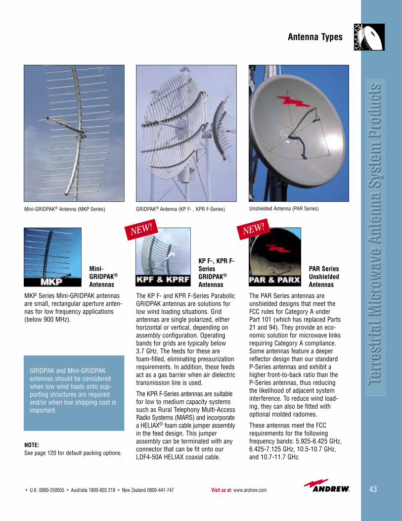
Mini-GRIDPAK®
Antennas
MKP Series Mini-GRIDPAK antennasare small, rectangular aperture anten-nas for low frequency applications(below 900 MHz).
Mini-GRIDPAK® Antenna (MKP Series)
GRIDPAK and Mini-GRIDPAKantennas should be consideredwhen low wind loads onto sup-porting structures are requiredand/or when low shipping cost isimportant.
KP F-, KPR F-SeriesGRIDPAK®
Antennas
The KP F- and KPR F-Series ParabolicGRIDPAK antennas are solutions forlow wind loading situations. Gridantennas are single polarized, eitherhorizontal or vertical, depending onassembly configuration. Operatingbands for grids are typically below3.7 GHz. The feeds for these arefoam-filled, eliminating pressurizationrequirements. In addition, these feedsact as a gas barrier when air dielectrictransmission line is used.
The KPR F-Series antennas are suitablefor low to medium capacity systemssuch as Rural Telephony Multi-AccessRadio Systems (MARS) and incorporatea HELIAX® foam cable jumper assemblyin the feed design. This jumperassembly can be terminated with anyconnector that can be fit onto ourLDF4-50A HELIAX coaxial cable.
GRIDPAK® Antenna (KP F- , KPR F-Series)
NEW!
PAR Series UnshieldedAntennas
The PAR Series antennas areunshielded designs that meet theFCC rules for Category A underPart 101 (which has replaced Parts21 and 94). They provide an eco-nomic solution for microwave linksrequiring Category A compliance.Some antennas feature a deeperreflector design than our standardP-Series antennas and exhibit ahigher front-to-back ratio than theP-Series antennas, thus reducingthe likelihood of adjacent systeminterference. To reduce wind load-ing, they can also be fitted withoptional molded radomes.
These antennas meet the FCCrequirements for the following frequency bands: 5.925-6.425 GHz,6.425-7.125 GHz, 10.5-10.7 GHz,and 10.7-11.7 GHz.
NOTE:See page 120 for default packing options.
NEW!
Unshielded Antenna (PAR Series)

Customer Service Center - Call toll-free from: • U.S.A., Canada and Mexico 1-800-255-147944
Powertools System Planning SoftwareThe Andrew Powertools system planning CD-ROMcontains an easy-to-use suite of system planning tools.These programs are especially useful for the design of ter-restrial microwave antenna systems:
• Andrew Microwave System Planner (AMSP)
• ezGuide™
• PSI Select Pressurization Planner
You can request the Powertools CD-ROM (Bulletin M400) or down-load individual software tools fromthe Andrew web site,www.andrew.com.
AMSP
The AMSP is a complete terrestrial microwave systemdesign tool. AMSP helps you with equipment selectionand system planning, including choices of terrestrialmicrowave antennas, waveguide, flex twists, accessories,and pressurization. The program generates custom solu-tions with standard Andrew products, automaticallychecking component compatibility and preventing thedesign of an incompatible system. After you complete thesystem design, AMSP provides you with a customized billof materials.
ezGuide
ezGuide software guides the design and ordering processfor microwave transmission lines. The exact componenttype, waveguide size, flange types, component dimen-sions, operating frequency band, and finish can be speci-fied with point-and-click options. Each product is picturedon the screen and diagrammed for your reference.
PSI Select Pressurization Planner
The PSI Select Pressurization Planner offers completeinformation on Andrew pressurization products andaccessories. The program performs system calculationsand dehydrator selection for either a new site or for modi-fying an existing site. PSI Select Pressurization Planneralso provides catalog information and several pressuriza-tion presentations in Microsoft® PowerPoint®.
Microsoft and PowerPoint are registered trademarks of the Microsoft Corporation.
AMSP
ezGuide
PSI Select Pressurization Planner
System Planning Software
• U.K. 0800-250055 • Australia 1800-803 219 • New Zealand 0800-441-747 Visit us at: www.andrew.com 45
Reflectors
Antennas are supplied with either one-piece reflectors ortwo-piece reflectors for on-site assembly. All 2-10 ftreflectors are one-piece; 12 and 15 ft reflectors are two-piece. Split (two-piece) reflectors are available as anoption for 8 and 10 ft antennas. Solid (one-piece) reflec-tors are available as an option for 12 ft antennas. KPSeries GRIDPAK® antennas are supplied completely disas-sembled.
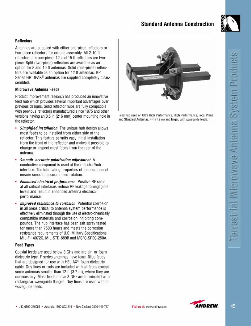
Microwave Antenna Feeds
Product improvement research has produced an innovativefeed hub which provides several important advantages overprevious designs. Solid reflector hubs are fully compatiblewith previous reflectors manufactured since 1975 and otherversions having an 8.5 in (216 mm) center mounting hole inthe reflector.
• Simplified installation. The unique hub design allowsmost feeds to be installed from either side of thereflector. This feature permits easy initial installationfrom the front of the reflector and makes it possible tochange or inspect most feeds from the rear of theantenna.
• Smooth, accurate polarization adjustment. A conductive compound is used at the reflector/hubinterface. The lubricating properties of this compoundensure smooth, accurate feed rotation.
• Enhanced electrical performance. Positive RF seals at all critical interfaces reduce RF leakage to negligiblelevels and result in enhanced antenna electrical performance.
• Improved resistance to corrosion. Potential corrosionin all areas critical to antenna system performance iseffectively eliminated through the use of electro-chemicallycompatible materials and corrosion inhibiting com-pounds. The hub interface has been salt spray testedfor more than 7500 hours and meets the corrosionresistance requirements of U.S. Military SpecificationsMIL-F-14072C, MIL-STD-889B and MSFC-SPEC-250A.
Feed Types
Coaxial feeds are used below 3 GHz and are air- or foam-dielectric type. F-series antennas have foam-filled feedsthat are designed for use with HELIAX® foam-dielectriccable. Guy lines or rods are included with all feeds exceptsome antennas smaller than 12 ft (3.7 m), where they areunnecessary. Most feeds above 3 GHz are terminated withrectangular waveguide flanges. Guy lines are used with allwaveguide feeds.
Standard Antenna Construction
Feed hub used on Ultra High Performance, HIgh Performance, Focal Planeand Standard Antennas, 4-ft (1.2 m) and larger, with waveguide feeds.

Customer Service Center - Call toll-free from: • U.S.A., Canada and Mexico 1-800-255-147946
Radomes
Radomes are used to protect microwave antennas againstaccumulation of ice, snow, and dirt and to reduce windloading. All Andrew shielded antennas include a planarradome. Antennas which include a radome are indicatedin the antenna specification tables on pages 116-119.Optional molded radomes, listed on page 118, are avail-able for most other solid reflector, standard unshieldedparabolic antennas.
Radomes for shielded antennas. All Andrew shieldedantennas, except ValuLine® include a flexible planarradome. The radome is stretched across the opening ofthe shield (through tensioning springs) flexing slightly inthe wind to shed ice and snow in most environments.
Two types of flexible planar radomes are used, TEGLAR®
and Hypalon. Hypalon is a rubber coated nylon and is pro-vided with HP and HPX series antennas. TEGLAR is apolymer-coated fiberglass material and is provided withHSX, UHX and UMX type antennas.
In addition, TEGLAR radomes are extremely durable, andexcel in resistance to heat, rain, snow, fungus, ice accu-mulation, corrosive atmosphere and ultraviolet light.Upgrades to TEGLAR on HP and HPX series is optional.
Pre-tensioned radomes. Some high performance antennas are supplied with a pre-tensioned radome. Pre-tensioned radomes are made from TEGLAR® materialbonded to a support ring. They replace the previouslyoffered spring tensioned design.
Radomes for standard antennas. Molded radomes aremanufactured of ABS plastic or fiberglass. They helpreduce tower wind loading and are optional for mostantennas.
Mounts
All microwave antennas are supplied with a vertical towermount. Roof, vertical tilt and horizontal tilt mounts areavailable as options.
Shields
Cylindrical shields, attached to the reflector rim, improvethe radiation pattern performance of parabolic antennas.RF absorbing material is placed at critical locations insidethe shield to reduce RF energy reflections.
Antenna Finish
Standard colors for microwave antennas and radomes arelisted in the table below. Other colors in compliance withU.S. FCC and U.S. FAA regulations or special applicationsare available on request. Unless otherwise specified,radomes supplied with special color antennas will be thestandard color.
For optional TEGLAR radome colors, see page 116.
Microwave Antenna and Radome Standard ColorsDescription Standard Color
Shielded Antennas Gray
Radomes for Shielded Antennas4-15 ft (1.2-4.6 m) White
Standard Antennas Gray
Molded Radomes for Standard Antennas Gray
GRIDPAK® and Mini-GRIDPAK® Antennas Unpainted aluminum
Standard Antenna Construction

• U.K. 0800-250055 • Australia 1800-803 219 • New Zealand 0800-441-747 Visit us at: www.andrew.com 47
Andrew offers the industry’s most comprehensive line ofantennas for point-to-point microwave communication.The extremely wide range of available antennas permitsyou to choose an antenna that is optimized for yourrequirements. Nearly 6000 different configurations areavailable from this catalog. In choosing an antenna, thefollowing basic parameters should be considered:
Operating frequency band. The antennas on pages 51-91are listed in order of ascending operating frequency.Antennas for simultaneous operation in two or morebands are offered on pages 93 and 94.
Radiation patterns determine an antenna’s ability to dis-criminate against unwanted signals under conditions ofradio congestion. Radiation patterns are dependent onantenna series, size, and frequency. A Radiation PatternEnvelope (RPE) comparison of various antenna series isshown at the right. For more information, see page 48.
Gain. For a given frequency band, gain is primarily a function of antenna size.
The gain of Andrew antennas is determined by either gain by comparison or by computer integration of the measured antenna patterns. The gain by integration methodmakes allowance for any additional signal losses such asohmic, VSWR and cross-polarized losses. Both methodsfollow the recommended procedures as stated in EIAStandard 195C.
Polarization. Most antennas are available in bothsingle- and dual-polarized versions. All can be used horizontally or vertically polarized and most havecontinuous polarization adjustment.
Pressurization. All antennas with air-dielectric coaxial orwaveguide feeds should be pressurized. F-Series antennaseliminate the need for pressurization equipment, since thefoam-filled feeds are void free and sealed to preclude thepresence of moisture.
Wind load. Survival ratings are specified on page 49.Wind forces for various antenna types and sizes are tabulated on pages 111-113. GRIDPAK® antennas, available below 3.7 GHz, have significantly lower windload than solid antenna types.
Shipping considerations. KP Series GRIDPAK® antennasare shipped disassembled, which results in very smallshipping volume. Most 8 ft (2.4 m) and larger solid antennas are available in two piece versions to reduceshipping volume. Refer to the table on page 122.
Microwave Antenna Selection Criteria
100
90
80
70
60
50
40
30
20
10
0
5 10 15 20 40 60 80 100 120 140 160 180
UHX Ultra High Performance Antennaand UMX Multiband AntennaStandard AntennaHP High Performance Antenna
Azimuth Degrees From Main Lobe
Ante
nna
Dire
ctiv
ity -
dB D
own
From
Mai
n Lo
be
RPE Comparison at 6 GHz
100
90
80
70
60
50
40
30
20
10
0
5 10 15 20 40 60 80 100 120 140 160 180
Ultra High Performance AntennaStandard AntennaGRIDPAK Antenna
RPE Comparison at 2 GHz
Ante
nna
Dire
ctiv
ity -
dB D
own
From
Mai
n Lo
be
Azimuth Degrees From Main Lobe
Customer Service Center - Call toll-free from: • U.S.A., Canada and Mexico 1-800-255-147948
Antenna ElectricalSpecifications
Radiation Pattern EnvelopesRadiation pattern envelopes (RPEs) published by Andrewpresent radiation pattern information in a form that is easyto use for planning radio systems. RPEs are available forall catalog microwave antennas. Copies are on file at theU.S. FCC, Industry Canada, BT, Telecom Australia, FrenchCNET, and many other administrations throughout theworld. U. S. FCC code numbers are assigned to Andrewantennas where applicable. Curves are presented in both rectangular coordinate graph and tabulated digitalformats.
Andrew software, included on the Powertools CD-ROM and downloadable fromwww.andrew.com, allows you to view RPEsfor the antennas listed in the catalog. Seepage 44 for more information.
Andrew RPEs represent the “worst peaks” envelope ofradiation patterns, measured on selected units, whichaccurately represent the antenna type. Parallel and cross-polar patterns are measured for both horizontal and vertical polarizations. Close manufacturing controlensures this performance is maintained.
Parallel and cross-polar response are represented for both horizontal and vertical polarizations. The curves areidentified as follows:
HH – Response of a horizontally polarized port to a horizontally polarized signal.
HV – Response of a horizontally polarized port to a vertically polarized signal.
VV – Response of a vertically polarized port to a vertically polarized signal.
VH – Response of a vertically polarized port to a horizontally polarized signal.
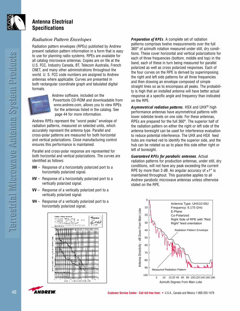
Preparation of RPEs. A complete set of radiation patterns comprises twelve measurements over the full360° of azimuth rotation measured under still, dry condi-tions. These cover horizontal and vertical polarizations foreach of three frequencies (bottom, middle and top) in theband, each of these in turn being measured for parallelpolarized as well as cross polarized responses. Each ofthe four curves on the RPE is derived by superimposingthe right and left side patterns for all three frequenciesand then drawing an envelope composed of simplestraight lines so as to encompass all peaks. The probabili-ty is high that an installed antenna will have better actualresponse at a specific angle and frequency than indicatedon the RPE.
Asymmetrical radiation patterns. HSX and UHX® highperformance antennas have asymmetrical patterns withlower sidelobe levels on one side. For these antennas,RPEs are prepared for the full 360°. The superior half ofthe radiation pattern on either the right or left side of theantenna boresight can be used for interference evaluationto reduce potential interference. The UHX and HSX feedhubs are marked red to identify the superior side, and thehub can be rotated so as to place this side either right orleft of boresight.
Guaranteed RPEs for parabolic antennas. Actual radiation patterns for production antennas, under still, dryconditions, will not have any peak exceeding the currentRPE by more than 3 dB. An angular accuracy of ±1° ismaintained throughout. This guarantee applies to allAndrew parabolic microwave antennas unless otherwisestated on the RPE.
100
90
80
70
60
50
40
30
20
10
0
5 10 15 20 40 60 80 100120 140 160 180
Radiation Pattern Envelope
Measured Radiation Pattern
Antenna Type: UHX10-59JFrequency: 6.175 GHzE-PlaneCo-PolarizedRight Side of RPE with “RedRight” feed orientation
Azimuth Degrees From Main Lobe
Ante
nna
Dire
ctiv
ity -
dB D
own
From
Mai
n Lo
be

• U.K. 0800-250055 • Australia 1800-803 219 • New Zealand 0800-441-747 Visit us at: www.andrew.com 49
Wind Survival and Deflection CharacteristicsSurvival Ratings Max. Deflection in 70 mph
Antenna Types Wind Velocity mph (km/h) Radial Ice, in (mm) (110 km/h) Wind, degrees
Standard AntennasWithout Radome 125 (200) 1 (25) 0.1With Standard Radome 125 (200) 1 (25) 0.1
UHX®, UMX®, UHP, HSX and HP Antennas 125 (200) 1 (25) 0.1
GRIDPAK® Antennas 125 (200) – –
Electrical DefinitionsThe following terms describe the electrical characteristicsfor Andrew microwave antennas. All rated electrical char-acteristics listed in the tables are guaranteed to be withinthe tolerances stated below. Factory measurements ofthese electrical characteristics are made under still, dry conditions using state-of-the art equipment and techniques ensuring high accuracy.
Frequency refers to the operating frequency band. Thesebands correspond with CCIR recommendations or com-mon allocations used throughout the world. It is usuallypossible to tune antennas for slightly different frequencyranges while retaining the same electrical characteristics.Other ranges can be accommodated on special order.
VSWR. Maximum, is the guaranteed peak Voltage-Standing-Wave-Ratio within the operating band.
Isolation between inputs of single-band, dual-polarizedantennas is 35 dB minimum unless otherwise specified.
Gain is stated in dBi (decibels over an isotropic radiator)at three frequencies: bottom, middle and top of band.Manufacturing tolerance for antenna gain is 0.2 dB unless otherwise specified. In the case of two-port, dual-polarized antennas, the specified gain refers to the average gain of the two ports, the gain of each port differing from the average gain by not more than 0.3 dB.
Front-to-back ratio in decibels. Denotes highest radiationrelative to the main beam, at 180° ±40°, across the band.Production antennas do not exceed rated values by morethan 2 dB unless stated otherwise.
Half-power beamwidth is the nominal total width of themain beam at the -3 dB points.
Cross-polarization discrimination, in dB, is the differencebetween the peak of the co-polarized main beam and themaximum cross-polarized signal over an angle twice the 3 dB beamwidth of the co-polarized main beam.
Power rating. All microwave antenna feeds are rated at150 watts.
Antenna Environmental RatingsStandard ratings. Microwave antennas, including mountsand radomes, where applicable, will withstand the simul-taneous wind and ice conditions specified in the tablebelow. Except where noted otherwise in the antenna listings, all antennas will remain operational within a temperature range of -50°C to 70°C (-58°F to 158°F), and meet all other requirements of EIA/TIA Standards222E and 195C.
High wind survival. Special antenna designs with windsurvival ratings up to 200 mph (320 km/h) are available.See pages 114-115.
Corrosive environments. Antennas designed for corrosiveenvironments are also available. See pages 114-115.

Customer Service Center - Call toll-free from: • U.S.A., Canada and Mexico 1-800-255-147950
Antenna Specifications and Ordering Information
Antenna Ordering Tables
Our line of terrestrial microwave antennas is presented inthe tables on pages 51-94. The tables are arranged byoperating frequency band, in ascending order. Within thetables, antennas are grouped by antenna type, and bydiameter.
Basic Antenna
The type numbers listed in the tables define the basicantenna, less options and accessories. The tables alsoinclude RPE numbers and define important electrical performance parameters of the antennas.
All of the antennas in this section include a feed, reflector and vertical tower mount. Refer to the “AntennaTypes” and “Antenna Construction” sections, pages 39-46for details.
Antenna Inputs
Connector and flange options for each antenna are listedwithin the ordering tables. Other flanges, available asoptions, may effect VSWR performance where noted.Contact Andrew for more details.
Flange options are discussed in detail on pages 114 and 115.
Radomes
All shielded antennas include either a TEGLAR® long-liferadome, a Hypalon coated nylon radome or a moldedthermoplastic planar radome, as specified in the tables.The TEGLAR long-life radome is optional for antennaswhich are normally supplied with the Hypalon radome.
Molded radomes are also available as an option for most standard (non-shielded, solid reflector) antennas.Radomes are not applicable for any grid types.
Radomes are discussed in detail on pages 116-119.
Regulatory Information
Any regulatory compliance pertaining to an antenna isnoted in its catalog entry.
Antenna Options
Andrew offers a variety of antenna options which allowyou to choose additional features or change features fromthe basic antenna offerings. Options are described indetail on pages 114-122.
• Input connectors and flanges
• Antenna colors
• Radomes
• Radome colors
• High wind survival antennas
• Corrosive environment antennas
• Packing type
• Packing quantity
• Reflector type
• Special purpose mounts
Accessories
In addition to the above options, Andrew offers the following accessories to enhance your antenna selection.Accessories are described in detail on pages 119, 123-126.
• Edge protection kits for TEGLAR® radome
• Port termination loads
• Additional side or bottom mounting struts
Replacement Components
Contact Andrew for information on replacement components.
• Reflectors
• Feeds
• Radomes and radome clip kits (page 119)
• Shield absorber kits
• Major hardware kits
• Mounts (page 96)
• Universal guy wire kits
• Shields
• Struts (page 96)

• U.K. 0800-250055 • Australia 1800-803 219 • New Zealand 0800-441-747 Visit us at: www.andrew.com 51
335 - 365 MHzAntenna Inputs. All antenna VSWR values are specified with 7/8” EIA connectors. Other optional inputs may result in equal or slightly higher VSWR. Contact Andrew for details.
Regulatory Compliance Cross F/B VSWRType Diameter RPE U.S. FCC ETSI ETSI Gain, dBi Beamwidth Pol. Ratio max.Number ft (m) Number(s) 101 74 78 Class Gain Low Mid-Band Top Horizontal Vertical Disc., dB dB (R.L., dB)
KPGRIDPAK® Antennas – Unpressurized Single PolarizedAntenna Inputs: 7/8” EIA, “F” Flange Female, Type N Female, and 7-16 DIN Female
KP6F-335 6 (2.0) 2978 – – – – – 15.0 15.2 15.4 30.5 24.2 23 19 1.3 (17.7)
KP8F-335 8 (2.4) 2119 – – – – – 15.6 15.7 15.8 21.4 19.6 17 16 1.3 (17.7)
KP10F-335 10 (3.0) 2933 – – – – – 17.7 18.1 18.5 20.6 15.5 23 22 1.3 (17.7)
KP13F-335 13 (4.0) 2952 – – – – – 20.1 20.1 20.4 15.2 13.5 25 23 1.3 (17.7)
MKPMini-GRIDPAK Antennas – Unpressurized Single PolarizedAntenna Inputs: 7/8” EIA, “F” Flange Female, Type N Female, and 7-16 DIN Female
MKP-335 6.6 x 3.3 3439 – – – – – 11.0 11.0 11.0 37 28 15 9 1.5 (14.0)(2 x 1)
365 - 403 MHzAntenna Inputs. All antenna VSWR values are specified with 7/8” EIA connectors. Other optional inputs may result in equal or slightly higher VSWR. Contact Andrew for details.
Regulatory Compliance Cross F/B VSWRType Diameter RPE U.S. FCC ETSI ETSI Gain, dBi Beamwidth Pol. Ratio max.Number ft (m) Number(s) 101 74 78 Class Gain Low Mid-Band Top Horizontal Vertical Disc., dB dB (R.L., dB)
KPGRIDPAK® Antennas – Unpressurized Single PolarizedAntenna Inputs: 7/8” EIA, “F” Flange Female, Type N Female, and 7-16 DIN Female
KP6F-365 6 (2.0) 3005 – – – – – 15.8 16.3 16.3 28.4 21.6 29 20 1.3 (17.7)
KP8F-365 8 (2.4) 2120 – – – – – 16.7 17.4 17.8 22.1 17.5 22 18 1.3 (17.7)
KP10F-365 10 (3.0) 2938 – – – – – 18.7 19.4 19.6 18.5 13.9 33 24 1.3 (17.7)
KP13F-365 13 (4.0) 2954 – – – – – 21.0 21.5 22.0 13.4 10.6 33 24 1.3 (17.7)
403 - 470 MHzAntenna Inputs. All antenna VSWR values are specified with 7/8” EIA connectors. Other optional inputs may result in equal or slightly higher VSWR. Contact Andrew for details.
Regulatory Compliance Cross F/B VSWRType Diameter RPE U.S. FCC ETSI ETSI Gain, dBi Beamwidth Pol. Ratio max.Number ft (m) Number(s) 101 74 78 Class Gain Low Mid-Band Top Horizontal Vertical Disc., dB dB (R.L., dB)
KPGRIDPAK® Antennas – Unpressurized Single PolarizedAntenna Inputs: 7/8” EIA, “F” Flange Female, Type N Female, and 7-16 DIN Female
KP6F-403 6 (2.0) 3008 – – – – – 16.4 16.3 16.6 22.9 19.3 27 20 1.35 (16.5)
KP8F-403 8 (2.4) 2123 – – – – – 17.7 17.5 18.0 19.7 16.3 28 20 1.35 (16.5)
KP10F-403 10 (3.0) 2944 – – – – – 20.0 19.6 20.4 16.8 12.6 30 22 1.35 (16.5)
KP13F-403 13 (4.0) 2958 – – – – – 22.0 22.2 22.6 13.0 13.0 30 24 1.35 (16.5)
MKPMini-GRIDPAK Antennas – Unpressurized Single PolarizedAntenna Inputs: 7/8” EIA, “F” Flange Female, Type N Female, and 7-16 DIN Female
MKP-403 6.6 x 3.3 3441 – – – – – 13.5 13.5 13.5 29 22 17 19 1.35 (16.5)(2 x 1)
Customer Service Center - Call toll-free from: • U.S.A., Canada and Mexico 1-800-255-147952
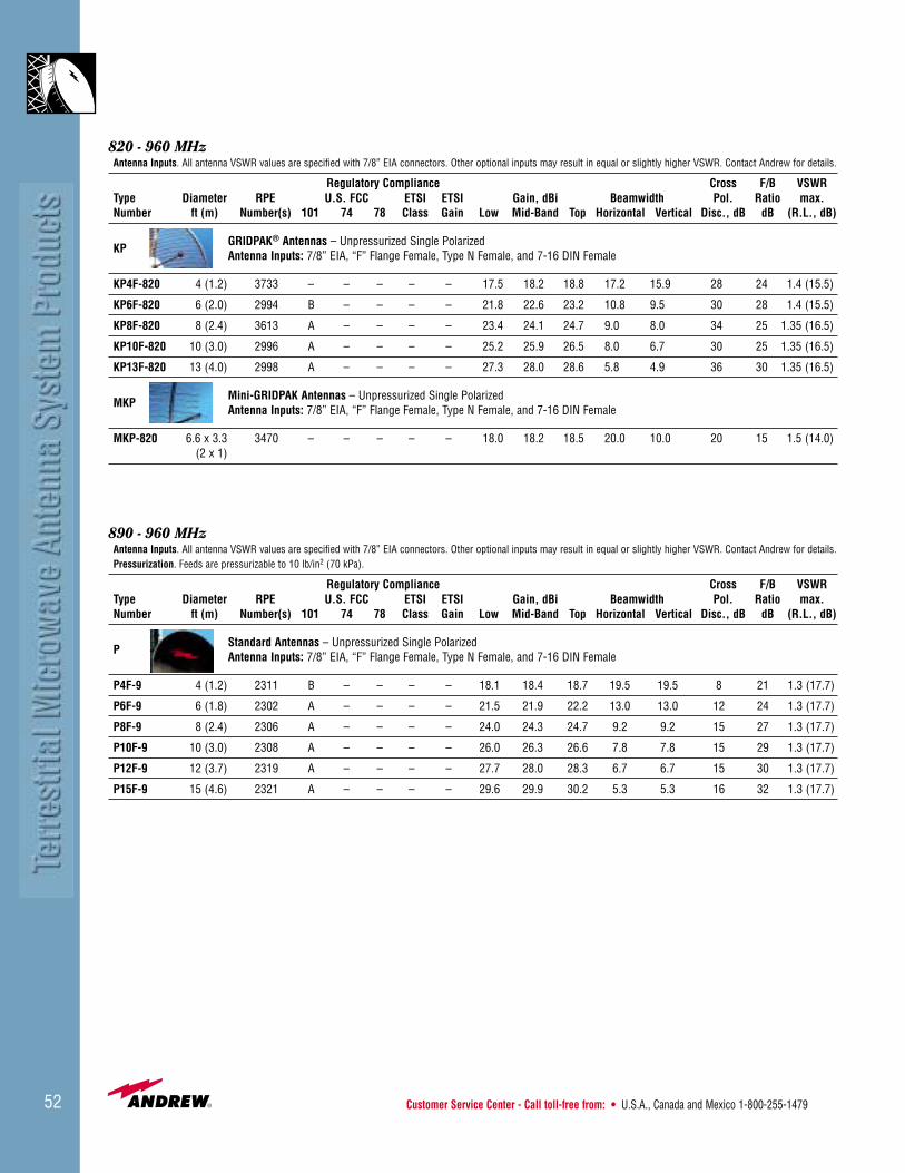
820 - 960 MHzAntenna Inputs. All antenna VSWR values are specified with 7/8” EIA connectors. Other optional inputs may result in equal or slightly higher VSWR. Contact Andrew for details.
Regulatory Compliance Cross F/B VSWRType Diameter RPE U.S. FCC ETSI ETSI Gain, dBi Beamwidth Pol. Ratio max.Number ft (m) Number(s) 101 74 78 Class Gain Low Mid-Band Top Horizontal Vertical Disc., dB dB (R.L., dB)
KPGRIDPAK® Antennas – Unpressurized Single PolarizedAntenna Inputs: 7/8” EIA, “F” Flange Female, Type N Female, and 7-16 DIN Female
KP4F-820 4 (1.2) 3733 – – – – – 17.5 18.2 18.8 17.2 15.9 28 24 1.4 (15.5)
KP6F-820 6 (2.0) 2994 B – – – – 21.8 22.6 23.2 10.8 9.5 30 28 1.4 (15.5)
KP8F-820 8 (2.4) 3613 A – – – – 23.4 24.1 24.7 9.0 8.0 34 25 1.35 (16.5)
KP10F-820 10 (3.0) 2996 A – – – – 25.2 25.9 26.5 8.0 6.7 30 25 1.35 (16.5)
KP13F-820 13 (4.0) 2998 A – – – – 27.3 28.0 28.6 5.8 4.9 36 30 1.35 (16.5)
MKPMini-GRIDPAK Antennas – Unpressurized Single PolarizedAntenna Inputs: 7/8” EIA, “F” Flange Female, Type N Female, and 7-16 DIN Female
MKP-820 6.6 x 3.3 3470 – – – – – 18.0 18.2 18.5 20.0 10.0 20 15 1.5 (14.0)(2 x 1)
890 - 960 MHzAntenna Inputs. All antenna VSWR values are specified with 7/8” EIA connectors. Other optional inputs may result in equal or slightly higher VSWR. Contact Andrew for details.Pressurization. Feeds are pressurizable to 10 lb/in2 (70 kPa).
Regulatory Compliance Cross F/B VSWRType Diameter RPE U.S. FCC ETSI ETSI Gain, dBi Beamwidth Pol. Ratio max.Number ft (m) Number(s) 101 74 78 Class Gain Low Mid-Band Top Horizontal Vertical Disc., dB dB (R.L., dB)
P Standard Antennas – Unpressurized Single PolarizedAntenna Inputs: 7/8” EIA, “F” Flange Female, Type N Female, and 7-16 DIN Female
P4F-9 4 (1.2) 2311 B – – – – 18.1 18.4 18.7 19.5 19.5 8 21 1.3 (17.7)
P6F-9 6 (1.8) 2302 A – – – – 21.5 21.9 22.2 13.0 13.0 12 24 1.3 (17.7)
P8F-9 8 (2.4) 2306 A – – – – 24.0 24.3 24.7 9.2 9.2 15 27 1.3 (17.7)
P10F-9 10 (3.0) 2308 A – – – – 26.0 26.3 26.6 7.8 7.8 15 29 1.3 (17.7)
P12F-9 12 (3.7) 2319 A – – – – 27.7 28.0 28.3 6.7 6.7 15 30 1.3 (17.7)
P15F-9 15 (4.6) 2321 A – – – – 29.6 29.9 30.2 5.3 5.3 16 32 1.3 (17.7)
• U.K. 0800-250055 • Australia 1800-803 219 • New Zealand 0800-441-747 Visit us at: www.andrew.com 53
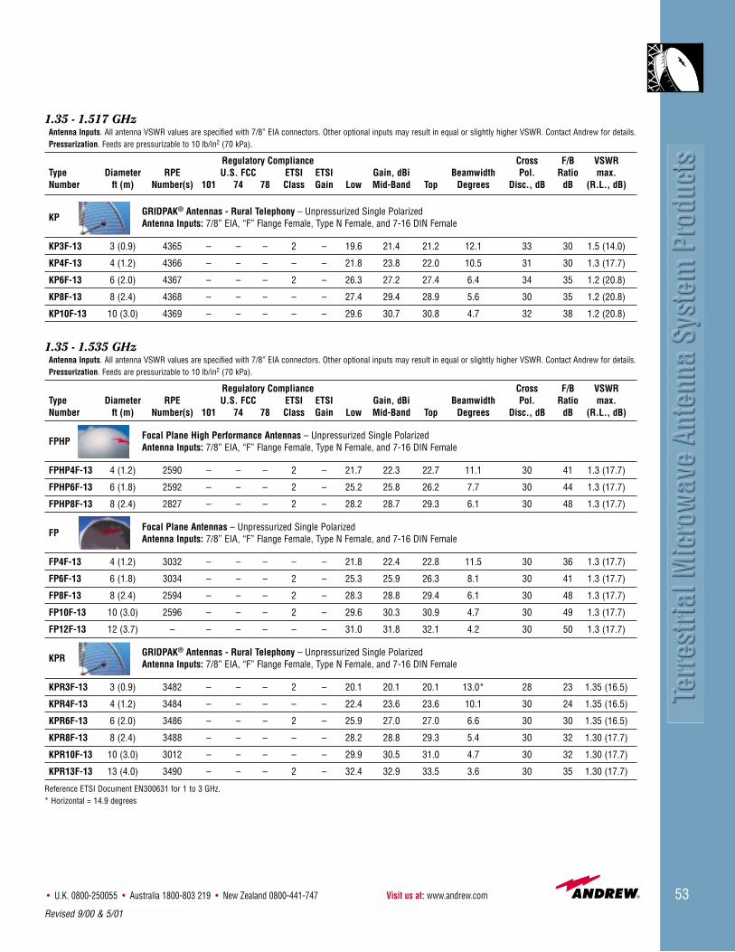
1.35 - 1.517 GHzAntenna Inputs. All antenna VSWR values are specified with 7/8” EIA connectors. Other optional inputs may result in equal or slightly higher VSWR. Contact Andrew for details.Pressurization. Feeds are pressurizable to 10 lb/in2 (70 kPa).
Regulatory Compliance Cross F/B VSWRType Diameter RPE U.S. FCC ETSI ETSI Gain, dBi Beamwidth Pol. Ratio max.Number ft (m) Number(s) 101 74 78 Class Gain Low Mid-Band Top Degrees Disc., dB dB (R.L., dB)
KPGRIDPAK® Antennas - Rural Telephony – Unpressurized Single PolarizedAntenna Inputs: 7/8” EIA, “F” Flange Female, Type N Female, and 7-16 DIN Female
KP3F-13 3 (0.9) 4365 – – – 2 – 19.6 21.4 21.2 12.1 33 30 1.5 (14.0)
KP4F-13 4 (1.2) 4366 – – – – – 21.8 23.8 22.0 10.5 31 30 1.3 (17.7)
KP6F-13 6 (2.0) 4367 – – – 2 – 26.3 27.2 27.4 6.4 34 35 1.2 (20.8)
KP8F-13 8 (2.4) 4368 – – – – – 27.4 29.4 28.9 5.6 30 35 1.2 (20.8)
KP10F-13 10 (3.0) 4369 – – – – – 29.6 30.7 30.8 4.7 32 38 1.2 (20.8)
1.35 - 1.535 GHzAntenna Inputs. All antenna VSWR values are specified with 7/8” EIA connectors. Other optional inputs may result in equal or slightly higher VSWR. Contact Andrew for details.Pressurization. Feeds are pressurizable to 10 lb/in2 (70 kPa).
Regulatory Compliance Cross F/B VSWRType Diameter RPE U.S. FCC ETSI ETSI Gain, dBi Beamwidth Pol. Ratio max.Number ft (m) Number(s) 101 74 78 Class Gain Low Mid-Band Top Degrees Disc., dB dB (R.L., dB)
FPHPFocal Plane High Performance Antennas – Unpressurized Single PolarizedAntenna Inputs: 7/8” EIA, “F” Flange Female, Type N Female, and 7-16 DIN Female
FPHP4F-13 4 (1.2) 2590 – – – 2 – 21.7 22.3 22.7 11.1 30 41 1.3 (17.7)
FPHP6F-13 6 (1.8) 2592 – – – 2 – 25.2 25.8 26.2 7.7 30 44 1.3 (17.7)
FPHP8F-13 8 (2.4) 2827 – – – 2 – 28.2 28.7 29.3 6.1 30 48 1.3 (17.7)
FPFocal Plane Antennas – Unpressurized Single PolarizedAntenna Inputs: 7/8” EIA, “F” Flange Female, Type N Female, and 7-16 DIN Female
FP4F-13 4 (1.2) 3032 – – – – – 21.8 22.4 22.8 11.5 30 36 1.3 (17.7)
FP6F-13 6 (1.8) 3034 – – – 2 – 25.3 25.9 26.3 8.1 30 41 1.3 (17.7)
FP8F-13 8 (2.4) 2594 – – – 2 – 28.3 28.8 29.4 6.1 30 48 1.3 (17.7)
FP10F-13 10 (3.0) 2596 – – – 2 – 29.6 30.3 30.9 4.7 30 49 1.3 (17.7)
FP12F-13 12 (3.7) – – – – – – 31.0 31.8 32.1 4.2 30 50 1.3 (17.7)
KPRGRIDPAK® Antennas - Rural Telephony – Unpressurized Single PolarizedAntenna Inputs: 7/8” EIA, “F” Flange Female, Type N Female, and 7-16 DIN Female
KPR3F-13 3 (0.9) 3482 – – – 2 – 20.1 20.1 20.1 13.0* 28 23 1.35 (16.5)
KPR4F-13 4 (1.2) 3484 – – – – – 22.4 23.6 23.6 10.1 30 24 1.35 (16.5)
KPR6F-13 6 (2.0) 3486 – – – 2 – 25.9 27.0 27.0 6.6 30 30 1.35 (16.5)
KPR8F-13 8 (2.4) 3488 – – – – – 28.2 28.8 29.3 5.4 30 32 1.30 (17.7)
KPR10F-13 10 (3.0) 3012 – – – – – 29.9 30.5 31.0 4.7 30 32 1.30 (17.7)
KPR13F-13 13 (4.0) 3490 – – – 2 – 32.4 32.9 33.5 3.6 30 35 1.30 (17.7)
Reference ETSI Document EN300631 for 1 to 3 GHz.* Horizontal = 14.9 degrees
Revised 9/00 & 5/01

Customer Service Center - Call toll-free from: • U.S.A., Canada and Mexico 1-800-255-147954
1.427 - 1.535 GHzAntenna Inputs. All antenna VSWR values are specified with 7/8” EIA connectors. Other optional inputs may result in equal or slightly higher VSWR. Contact Andrew for details.Pressurization. Feeds are pressurizable to 10 lb/in2 (70 kPa).
Regulatory Compliance Cross F/B VSWRType Diameter RPE U.S. FCC ETSI ETSI Gain, dBi Beamwidth Pol. Ratio max.Number ft (m) Number(s) 101 74 78 Class Gain Low Mid-Band Top Degrees Disc., dB dB (R.L., dB)
PL, Standard Antennas – Standard and Low VSWR, Unpressurized Single PolarizedP Antenna Inputs: 7/8” EIA, “F” Flange Female, Type N Female, and 7-16 DIN Female
P4F-15 4 (1.2) 1518 – – – 2 – 22.6 23.0 23.3 11.6 30 30 1.15 (23.1)
PL6F-15 6 (1.8) 1513 – – – 2 – 26.1 26.5 26.8 7.8 30 32 1.10 (26.4)
PL8F-15 8 (2.4) 1515 – – – 2 – 28.6 29.0 29.3 5.8 30 34 1.10 (26.4)
PL10F-15 10 (3.0) 1517 – – – 2 – 30.6 31.0 31.3 4.7 30 36 1.10 (26.4)
KPGRIDPAK® Antennas – F Series Unpressurized Single PolarizedAntenna Inputs: 7/8” EIA, “F” Flange Female, Type N Female, and 7-16 DIN Female
KP4F-15 4 (1.2) 3826 – – – – – 23.1 23.4 23.7 11.0 31 28 1.30 (17.7)
KP6F-15 6 (2.0) 3978 – – – 2 – 26.8 27.1 27.4 7.2 32 31 1.20 (20.8)
KP8F-15 8 (2.4) 4096 – – – – – 28.4 28.7 29.0 6.2 30 32 1.20 (20.8)
KP10F-15 10 (3.0) 2969 – – – 2 – 30.4 30.7 31.0 4.7 34 33 1.15 (23.1)
KP13F-15 13 (4.0) 2980 – – – 2 – 32.8 33.1 33.4 3.8 30 40 1.15 (23.1)
1.7 - 2.11 GHzAntenna Inputs. All antenna VSWR values are specified with 7/8” EIA connectors. Other optional inputs may result in equal or slightly higher VSWR. Contact Andrew for details.Pressurization. Feeds are pressurizable to 10 lb/in2 (70 kPa), except FPX Series 3 lb/in2 (20 kPa).
Regulatory Compliance Cross F/B VSWRType Diameter RPE U.S. FCC ETSI ETSI Gain, dBi Beamwidth Pol. Ratio max.Number ft (m) Number(s) 101 74 78 Class Gain Low Mid-Band Top Degrees Disc., dB dB (R.L., dB)
HPHigh Performance Antennas – Unpressurized Single PolarizedAntenna Inputs: 7/8” EIA and “F” Flange Female
HP6F-17 6 (1.8) 1370 – – – 2 – 27.7 28.6 29.6 6.0 25 44 1.10 (26.4)
HP8F-17 8 (2.4) 2252 A A – 2 – 30.2 31.1 32.0 4.5 30 50 1.10 (26.4)
HP10F-17 10 (3.0) 2254 A A – 2 – 32.1 33.1 34.1 3.7 34 52 1.10 (26.4)
HP12F-17 12 (3.7) 2256 A A – 2 – 33.7 34.6 35.6 3.0 30 56 1.10 (26.4)
HP15F-17 15 (4.6) 1381 A A – 2 – 35.7 36.6 37.5 2.4 30 58 1.10 (26.4)
PL, PStandard Antennas – Standard and Low VSWR, Unpressurized Single PolarizedAntenna Inputs: 7/8” EIA, “F” Flange Female, Type N Female, and 7-16 DIN Female
P2F-17 2 (1.8) 4344 – – – – – 18.2 19.7 19.9 15.3* 21 22 1.50 (14.0)
P4F-17 4 (1.2) 2298 – – – 2 – 23.9 24.8 25.7 9.0 30 30 1.20 (20.8)
PL6F-17 6 (1.8) 2274 B B – 2 – 27.7 28.6 29.5 6.0 30 36 1.10 (26.4)
PL8F-17 8 (2.4) 2276 A A – 2 – 30.2 31.1 32.0 4.5 30 39 1.10 (26.4)
PL10F-17 10 (3.0) 2278 A A – 2 – 32.1 33.1 34.0 3.7 34 42 1.10 (26.4)
PL12F-17 12 (3.7) 2280 A A – 2 – 33.7 34.6 35.5 3.0 30 45 1.10 (26.4)
PL15F-17 15 (4.6) 1377 A A – 2 – 35.7 36.6 37.5 2.4 30 48 1.10 (26.4)
Reference ETSI Document EN300631 for 1 to 3 GHz*Horizontal = 16.9 degrees
Revised 5/01

• U.K. 0800-250055 • Australia 1800-803 219 • New Zealand 0800-441-747 Visit us at: www.andrew.com 55
1.7 - 2.11 GHzRegulatory Compliance Cross F/B VSWR
Type Diameter RPE U.S. FCC ETSI ETSI Gain, dBi Beamwidth Pol. Ratio max.Number ft (m) Number(s) 101 74 78 Class Gain Low Mid-Band Top Degrees Disc., dB dB (R.L., dB)
FPFocal Plane Antennas – Dual PolarizedAntenna Inputs: 7/8” EIA and “F” Flange Female
FPX8-17* 8 (2.4) 6210 B B – 2 – 29.4 30.4 31.2 4.6 28 45 1.10 (26.4)
FPX10-17* 10 (3.0) 6209 B B – – – 31.5 32.3 33.1 3.7 30 50 1.10 (26.4)
FPX12-17* 12 (3.7) 6211 B B – 2 – 33.3 34.0 34.8 3.2 29 52 1.10 (26.4)
Focal Plane Antennas – Unpressurized Single PolarizedAntenna Inputs: 7/8” EIA, “F” Flange Female, Type N Female, and 7-16 DIN Female
FP8F-17 8 (2.4) 6219 B B – 2 – 29.9 30.8 31.9 4.6 30 49 1.10 (26.4)
FP10F-17 10 (3.0) 6221 A A – 2 – 31.9 32.8 33.8 3.7 30 51 1.10 (26.4)
FP12F-17 12 (3.7) 6223 A A – 2 – 33.6 34.3 35.3 3.1 30 54 1.10 (26.4)
KPGRIDPAK® Antennas – F-Series Unpressurized Single PolarizedAntenna Inputs: 7/8” EIA, “F” Flange Female, Type N Female, and 7-16 DIN Female
KP4F-17 4 (1.2) 3830 – – – 2 – 24.6 25.5 26.4 8.6 31 32 1.20 (20.8)KP6F-17 6 (2.0) 4077 B B – – – 28.3 29.3 30.2 5.5 33 36 1.10 (26.4)KP8F-17 8 (2.4) 4098 B B – – – 30.1 31.1 31.7 4.8 32 36 1.10 (26.4)KP10F-17 10 (3.0) 2971 A A – 2 – 31.9 32.8 33.7 3.7 38 42 1.10 (26.4)KP13F-17 12 (3.7) 2982 A A – – – 34.3 35.3 36.2 3.0 30 40 1.10 (26.4)
Continued from previous page
1.85 - 1.99 GHz **Antenna Inputs. All antenna VSWR values are specified with 7/8” EIA connectors. Other optional inputs may result in equal or slightly higher VSWR. Contact Andrew for details.Pressurization. Feeds are pressurizable to 10 lb/in2 (70 kPa), except PXL Series 3 lb/in2 (20 kPa).
Regulatory Compliance Cross F/B VSWRType Diameter RPE U.S. FCC ETSI ETSI Gain, dBi Beamwidth Pol. Ratio max.Number ft (m) Number(s) 101 74 78 Class Gain Low Mid-Band Top Degrees Disc., dB dB (R.L., dB)
UHPUltra High Performance Antennas – Single PolarizedAntenna Input: 7/8” EIA
UHP8-18 8 (2.4) 2168 A – – 2 – 30.8 31.1 31.4 4.8 33 62 1.08 (28.3)
UHP10-18 10 (3.0) 2169 A – – 2 – 32.6 33.0 33.3 4.2 32 62 1.08 (28.3)
UHP12-18 12 (3.7) 2170 A – – 2 – 34.4 34.7 35.0 3.3 32 66 1.08 (28.3)
Ultra High Performance Antennas – Unpressurized Single PolarizedAntenna Inputs: 7/8” EIA and “F” Flange Female
UHP8F-18 8 (2.4) 2168 A – – 2 – 30.8 31.1 31.4 4.8 33 62 1.10 (26.4)
UHP10F-18 10 (3.0) 2169 A – – 2 – 32.6 33.0 33.3 4.2 32 62 1.10 (26.4)
UHP12F-18 12 (3.7) 2170 A – – 2 – 34.4 34.7 35.0 3.3 32 66 1.10 (26.4)
PXLStandard Antennas – Dual PolarizedAntenna Input: 7/8” EIA
PXL8-18* 8 (2.4) 2286 B – – 2 – 31.0 31.2 31.5 4.6 28 43 1.10 (26.4)
PXL10-18* 10 (3.0) 2288 A – – 2 – 32.9 33.1 33.6 3.7 28 46 1.10 (26.4)
PXL12-18* 12 (3.7) 2290 A – – 2 – 34.5 34.7 35.2 3.0 28 48 1.10 (26.4)
Reference ETSI Documents EN300631 for 1 to 3 GHz* 3 lb/in2 (20 kPa) maximum ** Multiband antennas are available in this frequency band. See page 94.
Revised 5/01

Customer Service Center - Call toll-free from: • U.S.A., Canada and Mexico 1-800-255-147956
1.9 - 2.3 GHzAntenna Inputs. All antenna VSWR values are specified with 7/8” EIA connectors. Other optional inputs may result in equal or slightly higher VSWR. Contact Andrew for details.Pressurization. Feeds are pressurizable to 10 lb/in2 (70 kPa), except HPX, FPX, and PXL Series 3 lb/in2 (20 kPa).
Regulatory Compliance Cross F/B VSWRType Diameter RPE U.S. FCC ETSI ETSI Gain, dBi Beamwidth Pol. Ratio max.Number ft (m) Number(s) 101 74 78 Class Gain Low Mid-Band Top Degrees Disc., dB dB (R.L., dB)
UHPUltra High Performance Antennas – Single PolarizedAntenna Input: 7/8” EIA
UHP8-19 8 (2.4) 1444 A A – 2 – 31.1 31.9 32.7 4.2 30 57 1.20 (20.8)
UHP10-19 10 (3.0) 1445 A A – 2 – 32.9 33.7 34.5 3.6 30 60 1.20 (20.8)
UHP12-19 12 (3.7) 1446 A A – 2 – 34.6 35.4 36.2 2.9 30 64 1.20 (20.8)
Ultra High Performance Antennas – F-Series Unpressurized Single PolarizedAntenna Inputs: 7/8” EIA and “F” Flange Female
UHP8F-19 8 (2.4) 1447 A A – 2 – 31.1 31.9 32.7 4.2 30 57 1.20 (20.8)
UHP10F-19 10 (3.0) 1448 A A – 2 – 32.9 33.7 34.5 3.6 30 60 1.20 (20.8)
UHP12F-19 12 (3.7) 1449 A A – 2 – 34.6 35.4 36.2 2.9 30 64 1.20 (20.8)
HPX, High Performance Antennas – Dual PolarizedHP Antenna Input: 7/8” EIA
HPX8-19* 8 (2.4) 1430 A A – 1 – 31.1 32.0 32.9 4.1 28 48 1.10 (26.4)
HPX10-19* 10 (3.0) 1431 A A – 2 – 33.0 33.9 34.8 3.3 28 53 1.10 (26.4)
HPX12-19* 12 (3.7) 1432 A A – 2 – 34.6 35.5 36.4 2.8 30 55 1.10 (26.4)
HPX15-19* 15 (4.6) 1441 A A – 2 – 36.5 37.4 38.3 2.2 28 56 1.10 (26.4)
High Performance Antennas – F-Series Unpressurized Dual PolarizedAntenna Inputs: 7/8” EIA and “F” Flange Female
HPX8F-19 8 (2.4) 2573 A A – 1 – 31.1 32.0 32.9 4.1 28 48 1.20 (20.8)
HPX10F-19 10 (3.0) 2575 A A – 2 – 33.0 33.9 34.8 3.3 28 43 1.20 (20.8)
High Performance Antennas – F-Series Unpressurized Single PolarizedAntenna Inputs: 7/8” EIA and “F” Flange Female
HP6F-19 6 (1.8) 1450 B B – 2 – 28.5 29.4 30.3 5.5 25 46 1.10 (26.4)
HP8F-19 8 (2.4) 2262 A A – 2 – 31.0 31.9 32.8 4.1 30 50 1.10 (26.4)
HP10F-19 10 (3.0) 2264 A A – 2 – 32.9 33.8 34.7 3.3 30 53 1.10 (26.4)
HP12F-19 12 (3.7) 2267 A A – 2 – 34.5 35.4 36.3 2.8 30 57 1.10 (26.4)
HP15F-19 15 (4.6) 1409 A A – 2 – 36.5 37.4 38.3 2.2 30 59 1.10 (26.4)
PXL, Standard Antennas – Dual Polarized Low VSWRPL Antenna Inputs: 7/8” EIA
PXL8-19* 8 (2.4) 1426 A A – 2 – 31.1 32.0 32.9 4.1 28 43 1.10 (26.4)
PXL10-19* 10 (3.0) 1427 A A – 2 – 33.0 33.9 34.8 3.3 28 45 1.10 (26.4)
PXL12-19* 12 (3.7) 1428 A A – 2 – 34.6 35.5 36.4 2.8 28 48 1.10 (26.4)
PXL15-19* 15 (4.6) 1429 A A – 2 – 36.5 37.4 38.3 2.2 28 48 1.10 (26.4)
Standard Antennas – Unpressurized Dual Polarized Low VSWRAntenna Inputs: 7/8” EIA and “F” Flange Female
PXL8F-19 8 (2.4) 2563 A A – 2 – 31.1 32.0 32.9 4.1 28 43 1.20 (20.8)
PXL10F-19 10 (3.0) 2565 A A – 2 – 33.0 33.9 34.8 3.3 28 45 1.20 (20.8)
Standard Antennas – Unpressurized Single Polarized Standard and Low VSWRAntenna Inputs: 7/8” EIA, “F” Flange Female, Type N Female, and 7-16 DIN Female
P2F-19 2 (0.6) 4390 – – – – – 19.3 20.5 21.3 13.8 30 25 1.50 (14.0)
P4F-19 4 (1.2) 1863 – – – 2 – 24.8 25.7 26.6 8.2 30 33 1.20 (20.8)
PL6F-19 6 (1.8) 2202 B B – 2 – 28.5 29.4 30.3 5.5 30 37 1.10 (26.4)
PL8F-19 8 (2.4) 2204 A A – 2 – 31.0 31.9 32.8 4.1 30 40 1.10 (26.4)
PL10F-19 10 (3.0) 1403 A A – 2 – 32.9 33.8 34.7 3.3 30 44 1.10 (26.4)
PL12F-19 12 (3.7) 1404 A A – 2 – 34.5 35.4 36.3 2.8 30 46 1.10 (26.4)
PL15F-19 15 (4.6) 1405 A A – 2 – 36.5 37.4 38.3 2.2 30 50 1.10 (26.4)
Reference ETSI Document EN300631 for 1 to 3 GHz * 3 lb/in2 (20 kPa) maximum
Revised 7/00 & 5/01

• U.K. 0800-250055 • Australia 1800-803 219 • New Zealand 0800-441-747 Visit us at: www.andrew.com 57
Continued from previous page
1.9 - 2.3 GHzAntenna Inputs. All antenna VSWR values are specified with 7/8” EIA connectors. Other optional inputs may result in equal or slightly higher VSWR. Contact Andrew for details.Pressurization. Feeds are pressurizable to 10 lb/in2 (70 kPa), except HPX, FPX, and PXL Series 3 lb/in2 (20 kPa).
Regulatory Compliance Cross F/B VSWRType Diameter RPE U.S. FCC ETSI ETSI Gain, dBi Beamwidth Pol. Ratio max.Number ft (m) Number(s) 101 74 78 Class Gain Low Mid-Band Top Degrees Disc., dB dB (R.L., dB)
FPX, Focal Plane Antennas – Dual PolarizedFP Antenna Inputs: 7/8” EIA
FPX8-19* 8 (2.4) 6410 – – – – – 30.4 31.2 32.0 41 25 47 1.10 (26.4)
FPX10-19* 10 (3.0) 6413 A A – 2 – 32.3 33.1 33.9 3.3 29 52 1.10 (26.4)
FPX12-19* 12 (3.7) 6415 A A – 2 – 34.0 34.8 34.9 2.8 29 52 1.10 (26.4)
Focal Plane Antennas – Unpressurized Single PolarizedAntenna Inputs: 7/8” EIA and “F” Flange Female
FP8F-19 8 (2.4) 6408 A A – 2 – 30.5 31.4 32.2 4.1 30 50 1.10 (26.4)
FP10F-19 10 (3.0) 6409 A A – 2 – 32.2 33.1 34.0 3.3 30 53 1.10 (26.4)
FP12F-19 12 (3.7) 6406 A A – 2 – 33.8 34.7 35.6 2.8 30 55 1.10 (26.4)
KPGRIDPAK® Antennas – Unpressurized Single PolarizedAntenna Inputs: 7/8” EIA, “F” Flange Female, Type N Female, and 7-16 DIN Female
KP3F-19 3 (0.9) 4391 – – – 2 – 23.2 24.1 24.8 10.2 30 30 1.30 (17.7)
KP4F-19 4 (1.2) 3834 – – – 2 – 25.5 26.4 27.2 7.7 29 32 1.20 (20.8)
KP6F-19 6 (2.0) 4076 B B – 2 – 29.3 30.2 31.0 5.0 32 36 1.10 (26.4)
KP8F-19 8 (2.4) 4100 A A – 2 – 31.0 31.8 32.6 4.6 32 39 1.10 (26.4)
KP10F-19 10 (3.0) 2973 A A – 2 – 32.8 33.7 34.5 3.3 35 41 1.10 (26.4)
KP13F-19 13 (4.0) 2984 A A – – – 35.3 36.2 37.0 2.8 30 40 1.10 (26.4)
2.1 - 2.2 GHzAntenna Inputs. All antenna VSWR values are specified with 7/8” EIA connectors. Other optional inputs may result in equal or slightly higher VSWR. Contact Andrew for detailsPressurization. Feeds are pressurizable to 10 lb/in2 (70 kPa), except UHX Series 3 lb/in2 (20 kPa).
Regulatory Compliance Cross F/B VSWRType Diameter RPE U.S. FCC ETSI ETSI Gain, dBi Beamwidth Pol. Ratio max.Number ft (m) Number(s) 101 74 78 Class Gain Low Mid-Band Top Degrees Disc., dB dB (R.L., dB)
UHXUltra High Performance Antennas – Dual PolarizedAntenna Inputs: 7/8” EIA
UHX8-21* 8 (2.4) 2148 2149 A A - 2 - 31.9 32.1 32.3 4.2 30 58 1.10 (26.4)
UHX10-21* 10 (3.0) 2144 2145 A A - 2 - 33.8 34.0 34.2 3.6 32 62 1.10 (26.4)
UHX12-21* 12 (3.7) 2147 2146 A A - 2 - 35.4 35.6 35.8 2.8 32 67 1.10 (26.4)
Ultra High Performance Antennas – F-Series Unpressurized Single PolarizedAntenna Inputs: 7/8” EIA and “F” Flange Female
UHX8F-21 8 (2.4) 2148 2149 A A - 2 - 31.9 32.1 32.3 4.2 30 58 1.20 (20.8)
UHX10F-21 10 (3.0) 2145 2144 A A - 2 - 33.8 34.0 34.2 3.6 32 62 1.20 (20.8)
UHX12F-21 12 (3.7) 2147 2146 A A - 2 - 35.4 35.6 35.8 2.8 32 67 1.20 (20.8)
Reference ETSI Document EN300631 for 1 to 3 GHz* 3 lb/in2 (20 kPa) maximum **Horizontal = 8.9 degrees
**
Revised 5/01
Customer Service Center - Call toll-free from: • U.S.A., Canada and Mexico 1-800-255-147958
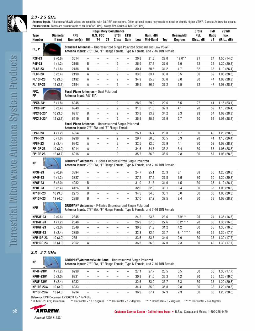
2.3 - 2.5 GHzAntenna Inputs. All antenna VSWR values are specified with 7/8” EIA connectors. Other optional inputs may result in equal or slightly higher VSWR. Contact Andrew for details.Pressurization. Feeds are pressurizable to 10 lb/in2 (20 kPa), except FPX Series 3 lb/in2 (20 kPa).
Regulatory Compliance Cross F/B VSWRType Diameter RPE U.S. FCC ETSI ETSI Gain, dBi Beamwidth Pol. Ratio max.Number ft (m) Number(s) 101 74 78 Class Gain Low Mid-Band Top Degrees Disc., dB dB (R.L., dB)
PL, PStandard Antennas – Unpressurized Single Polarized Standard and Low VSWRAntenna Inputs: 7/8” EIA, “F” Flange Female, Type N Female, and 7-16 DIN Female
P2F-23 2 (0.6) 3014 – – – – – 20.8 21.6 22.0 12.0** 21 24 1.50 (14.0)
P4F-23 4 (1.2) 2198 B – – 2 – 26.9 27.3 27.6 6.9 32 36 1.20 (20.8)
PL6F-23 6 (1.8) 2188 B – – 2 – 30.4 30.8 31.2 4.7 32 36 1.10 (26.4)
PL8F-23 8 (2.4) 2190 A – – 2 – 33.0 33.4 33.8 3.5 30 39 1.08 (28.3)
PL10F-23 10 (3.0) 2192 A – – 2 – 34.9 35.3 35.6 3.0 30 44 1.08 (28.3)
PL12F-23 12 (3.7) 2194 A – – 2 – 36.5 36.9 37.2 2.5 32 47 1.08 (28.3)
FPX, Focal Plane Antennas – Dual PolarizedFP Antenna Input: 7/8” EIA
FPX6-23* 6 (1.8) 6945 – – – 2 – 28.9 29.2 29.6 5.5 27 41 1.15 (23.1)
FPX8-23* 8 (2.4) 6949 – – – 2 – 31.5 31.8 32.3 4.1 28 52 1.10 (26.4)
FPX10-23* 10 (3.0) 6917 B – – 2 – 33.8 33.9 34.2 3.3 29 54 1.08 (28.3)
FPX12-23* 12 (3.7) 6919 B – – 2 – 35.5 35.6 35.9 2.7 30 56 1.08 (28.3)
Focal Plane Antennas – Unpressurized Single PolarizedAntenna Inputs: 7/8” EIA and “F” Flange Female
FP4F-23 4 (1.2) 6954 – – – 2 – 26.1 26.4 26.8 7.7 30 40 1.20 (20.8)
FP6F-23 6 (1.8) 6938 A – – 2 – 29.7 30.3 30.5 5.3 28 41 1.10 (26.4)
FP8F-23 8 (2.4) 6942 A – – 2 – 32.5 32.6 32.9 4.1 30 52 1.08 (28.3)
FP10F-23 10 (3.0) 6914 A – – 2 – 34.6 34.7 35.2 3.4 30 53 1.08 (28.3)
FP12F-23 12 (3.7) 6916 A – – 2 – 35.7 36.3 36.5 2.8 30 57 1.08 (28.3)
KPGRIDPAK® Antennas – F-Series Unpressurized Single PolarizedAntenna Inputs: 7/8” EIA, “F” Flange Female, Type N Female, and 7-16 DIN Female
KP3F-23 3 (0.9) 3394 – – – – – 24.7 25.1 25.3 8.1 38 30 1.20 (20.8)
KP4F-23 4 (1.2) 3837 – – – – – 27.2 27.5 27.8 6.9 30 30 1.20 (20.8)
KP6F-23 6 (2.0) 4082 B – – – – 31.0 31.3 31.6 4.5 30 36 1.10 (26.4)
KP8F-23 8 (2.4) 4126 B – – – – 32.6 32.9 33.1 3.4 30 35 1.08 (28.3)
KP10F-23 10 (3.0) 2975 B – – – – 34.5 34.8 35.1 3.0 30 38 1.08 (28.3)
KP13F-23 13 (4.0) 2986 B – – – – 37.0 37.2 37.5 2.4 30 38 1.08 (28.3)
KPRGRIDPAK® Antennas – F-Series Unpressurized Single PolarizedAntenna Inputs: 7/8” EIA, “F” Flange Female, Type N Female, and 7-16 DIN Female
KPR3F-23 2 (0.6) 2345 – – – – – 24.2 23.6 23.6 7.9*** 25 24 1.35 (16.5)
KPR4F-23 4 (1.2) 2348 – – – – – 26.9 27.3 27.6 6.2**** 28 30 1.35 (16.5)
KPR6F-23 6 (2.0) 2349 – – – – – 30.8 31.3 31.2 4.2 30 35 1.35 (16.5)
KPR8F-23 8 (2.4) 2350 – – – – – 32.3 32.4 32.7 3.1***** 30 36 1.30 (17.7)
KPR10F-23 10 (3.0) 2351 – – – – – 33.5 33.7 34.0 2.9 30 38 1.30 (17.7)
KPR13F-23 13 (4.0) 2352 A – – – – 36.5 36.8 37.0 2.3 30 40 1.30 (17.7)
2.3 - 2.7 GHz
KPGRIDPAK®/Antennas/Wide Band – Unpressurized Single PolarizedAntenna Inputs: 7/8” EIA, “F” Flange Female, Type N Female, and 7-16 DIN Female
KP4F-23W 4 (1.2) 6230 – – – – – 27.1 27.7 28.5 6.5 30 30 1.30 (17.7)
KP6F-23W 6 (2.0) 6231 – – – – – 30.9 31.5 32.3 4.2 30 35 1.25 (19.0)
KP8F-23W 8 (2.4) 6232 – – – – – 32.5 33.0 33.7 3.3 30 35 1.20 (20.8)
KP10F-23W 10 (3.0) 6233 – – – – – 34.4 35.0 35.8 2.8 30 38 1.20 (20.8)
KP13F-23W 13 (4.0) 6234 – – – – – 36.9 37.4 37.9 2.3 30 38 1.20 (20.8)Reference ETSI Document EN300631 for 1 to 3 GHz* 3 lb/in2 (20 kPa) maximum ** Horizontal = 13.3 degrees *** Horizontal = 8.7 degrees **** Horizontal = 6.7 degrees ***** Horizontal = 3.4 degrees
Revised 7/00 & 5/01

• U.K. 0800-250055 • Australia 1800-803 219 • New Zealand 0800-441-747 Visit us at: www.andrew.com 59
2.45 - 2.5 GHzAntenna Inputs. All antenna VSWR values are specified with 7/8” EIA connectors. Other optional inputs may result in equal or slightly higher VSWR. Contact Andrew for details.Pressurization. Feeds are pressurizable to 10 lb/in2 (70 kPa).
Regulatory Compliance Cross F/B VSWRType Diameter RPE U.S. FCC ETSI ETSI Gain, dBi Beamwidth Pol. Ratio max.Number ft (m) Number(s) 101 74 78 Class Gain Low Mid-Band Top Degrees Disc., dB dB (R.L., dB)
PStandard Antennas – Unpressurized Single PolarizedAntenna Inputs: 7/8” EIA, “F” Flange Female, Type N Female, and 7-16 DIN Female
P6F-24 6 (1.8) 2205 B – – 2 – 30.9 31.0 31.1 4.3 28 36 1.30 (17.7)
P8F-24 8 (2.4) 2207 A – – 2 – 33.4 33.5 33.6 3.2 28 39 1.30 (17.7)
2.48 - 2.7 GHzAntenna Inputs. All antenna VSWR values are specified with 7/8” EIA connectors. Other optional inputs may result in equal or slightly higher VSWR. Contact Andrew for details.Pressurization. Feeds are pressurizable to 10 lb/in2 (70 kPa) except FPX Series 3 lb/in2 (20 kPa).
Regulatory Compliance Cross F/B VSWRType Diameter RPE U.S. FCC ETSI ETSI Gain, dBi Beamwidth Pol. Ratio max.Number ft (m) Number(s) 101 74 78 Class Gain Low Mid-Band Top Degrees Disc., dB dB (R.L., dB)
HPHigh Performance Antennas – Unpressurized Single PolarizedAntenna Inputs: 7/8” EIA and “F” Flange Female
HP4F-25 4 (1.2) 1038 – – – 2 – 27 27.3 27.6 6.7 30 43 1.20 (20.8)
HP6F-25 6 (1.8) 1322E – – – 2 – 31.1 31.4 31.7 4.6 28 50 1.10 (26.4)
HP8F-25 8 (2.4) 1314 – – – 2 – 33.7 34 34.3 3.1 30 52 1.08 (28.3)
HP10F-25 10 (3.0) 3000 – – – 2 – 35.6 35.9 36.2 2.7 30 55 1.08 (28.3)
HP12F-25 12 (3.7) 1318 – – – 2 – 37.2 37.5 37.8 2.3 30 54 1.08 (28.3)
PL,PStandard Antennas – Unpressurized Single Polarized Standard and Low VSWRAntenna Inputs: 7/8” EIA, “F” Flange Female, Type N Female, and 7-16 DIN Female
P4F-25 4 (1.2) 1268 – – – – – 27.6 27.9 28.2 6.3 30 32 1.20 (20.8)
PL6F-25 6 (1.8) 1308 – – – – – 31.1 31.4 31.7 4.2 28 36 1.10 (26.4)
PL8F-25 8 (2.4) 1309 – – – 2 – 33.6 33.9 34.2 3.1 30 39 1.08 (28.3)
PL10F-25 10 (3.0) 1310 – – – 2 – 35.6 35.9 36.2 2.7 30 42 1.08 (28.3)
PL12F-25 12 (3.7) 1320 – – – 2 – 37.1 37.4 37.7 2.2 30 44 1.08 (28.3)
FPX, Focal Plane Antennas – Dual PolarizedFP Antenna Inputs: 7/8” EIA
FPX6-25* 6 (1.8) 6947 – – – – – 29.6 30.0 30.3 5.0 27 42 1.15 (23.1)
FPX8-25* 8 (2.4) 6951 – – – – – 32.3 32.6 32.7 5.0 27 52 1.15 (26.4)
FPX10-25* 10 (3.0) 6909 – – – 2 – 34.2 34.6 34.9 3.1 30 54 1.08 (28.3)
FPX12-25* 12 (3.7) 6911 – – – 2 – 35.9 36.3 36.8 2.6 30 56 1.08 (28.3)
Focal Plane Antennas – F-Series Unpressurized Single PolarizedAntenna Inputs: 7/8” EIA, “F” Flange Female, Type N Female, and 7-16 DIN Female
FP4F-25 4 (1.2) 6956 – – – 2 – 26.8 27.1 27.5 7.2 30 41 1.20 (20.8)
FP6F-25 6 (1.8) 6940 – – – 2 – 30.5 30.6 31.0 4.9 28 44 1.10 (26.4)
FP8F-25 8 (2.4) 6944 – – – 2 – 32.9 33.4 33.5 3.9 30 52 1.08 (26.4)
FP10F-25 10 (3.0) 6905 – – – 2 – 35.2 35.5 35.8 3.2 30 55 1.08 (28.3)
FP12F-25 12 (3.7) 6908 – – – 2 – 36.5 36.9 37.3 2.6 30 57 1.08 (28.3)
KPGRIDPAK® Antennas – Unpressurized Single PolarizedAntenna Inputs: 7/8” EIA, “F” Flange Female, Type N Female, and 7-16 DIN Female
KP3F-25 3 (0.9) 3395 – – – – – 25.3 25.2 25.4 7.7 32 30 1.20 (20.8)
KP4F-25 4 (1.2) 3841 – – – – – 27.8 28.2 28.6 6.1 30 31 1.20 (20.8)
KP6F-25 6 (2.0) 4084 – – – – – 31.6 32.0 32.4 4.0 30 35 1.10 (26.4)
KP8F-25 8 (2.4) 4128 – – – – – 33.1 33.6 33.8 3.2 30 37 1.08 (28.3)
KP10F-25 10 (3.0) 2977 – – – – – 35.1 35.5 35.9 2.7 31 38 1.08 (28.3)
KP13F-25 13 (4.0) 2988 – – – – – 37.5 37.8 38.0 2.3 30 38 1.08 (28.3)
Reference ETSI Document EN300631 for 1 to 3 GHz * 3 lb/in2 (20 kPa) maximum **Horizontal = 6.9 degrees
**
Revised 7/00 & 5/01\

Customer Service Center - Call toll-free from: • U.S.A., Canada and Mexico 1-800-255-147960
3.4 - 3.7 GHz* with Coaxial FeedsAntenna Inputs. All antenna VSWR values are specified with 7/8” EIA connectors. Other optional inputs may result in equal or slightly higher VSWR. Contact Andrew for details.Pressurization. Feeds are pressurizable to 10 lb/in2 (70 kPa).
Regulatory Compliance Cross F/B VSWRType Diameter RPE U.S. FCC ETSI ETSI Gain, dBi Beamwidth Pol. Ratio max.Number ft (m) Number(s) 101 74 78 Class Gain Low Mid-Band Top Degrees Disc., dB dB (R.L., dB)
HPHigh Performance Antennas – Unpressurized Single PolarizedAntenna Inputs: 7/8” EIA, “F” Flange Female, Type N Female, and 7-16 DIN Female
HP2F-34 2 (0.6) 4416 – – – – – 22.7 23 23 10.7 30 34 1.35 (16.5)HP4F-34 4 (1.2) 4418 – – – 1 1 29.1 29.5 29.8 4.7 30 41 1.30 (17.7)HP6F-34 6 (1.8) 4420 – – – 1 2 32.9 33.3 33.6 3.5 30 44 1.20 (20.8)HP8F-34 8 (2.4) 4422 – – – 1 2 35 35.4 35.7 2.5 30 48 1.20 (20.8)
PStandard Antennas – Unpressurized Single PolarizedAntenna Inputs: 7/8” EIA, “F” Flange Female, Type N Female, and 7-16 DIN Female
P2F-34 2 (0.6) 4415 – – – – – 24.3 24.5 25 9 30 26.5 1.35 (16.5)P4F-34 4 (1.2) 4417 – – – 1 1 29.6 30 30.3 4.5 30 33 1.30 (17.7)P6F-34 6 (1.8) 4419 – – – – – 33.7 33.6 33.6 3.3 30 36 1.20 (20.8)P8F-34 8 (2.4) 4421 – – – 1 2 35.2 35.6 35.9 2.6 30 40 1.20 (20.8)
3.4 - 3.9 GHz* with Waveguide FeedsAntenna Inputs. All antenna VSWR values are specified with CPR and PDR flanges. Other optional flanges may result in equal or slightly higher VSWR. Contact Andrew for details.Pressurization. Feeds are pressurizable to 5 lb/in2 (35 kPa), except FP Series 10 lb/in2 (70 kPa).
Regulatory Compliance Cross F/B VSWRType Diameter RPE U.S. FCC ETSI ETSI Gain, dBi Beamwidth Pol. Ratio max.Number ft (m) Number(s) 101 74 78 Class Gain Low Mid-Band Top degrees Disc., dB dB (R.L., dB)
UHXUltra High Performance Antennas– Dual PolarizedAntenna Inputs: CPR229G and PDR40
UHX8-34** 8 (2.4) 1469 1470 – – – 2 2 36.2 36.9 37.5 2.4 30 62 1.06 (30.7)UHX10-34** 10 (3.0) 1472 1471 B – – 2 2 38.1 38.8 39.4 1.8 30 62 1.06 (30.7)UHX12-34** 12 (3.7) 1473 1474 B – – 2 2 39.6 40.4 41.0 1.5 40 65 1.06 (30.7)UHX15-34** 15 (4.6) 1485 1486 A – – 2 2 41.6 42.3 42.9 1.2 30 66 1.06 (30.7)
HSXHigh Performance Antennas – Super High Cross Polarization Discrimination – Dual PolarizedAntenna Inputs: CPR229G and PDR40
HSX8-34** 8 (2.4) 1528 1530 B – – 3 2 36.1 36.6 37.1 2.4 40 67 1.06 (30.7)HSX10-34** 10 (3.0) 1534 1532 B – – 3 2 37.7 38.2 38.7 1.8 40 69 1.06 (30.7)HSX12-34** 12 (3.7) 1536 1538 B – – 3 2 39.6 40.1 40.6 1.5 40 70 1.06 (30.7)HSX15-34** 15 (4.6) 1540 1542 A – – 3 2 41.6 42.1 42.6 1.2 40 72 1.06 (30.7)
FPFocal Plane Antennas – Single PolarizedAntenna Inputs: CPR229G and PDR40
FP10-34 10 (3.0) 6605 – – – 1 2 37.0 38.3 38.8 1.9 28 60 1.06 (30.7)FP12-34 12 (3.7) 6601 B – – 2 2 39.3 39.8 40.3 1.6 29 62 1.06 (30.7)
Reference ETSI Document EN300833 for 3 to 60 GHz *Multiband antennas are available in this frequency band. See page 93. **5 lb/in2 (35 kPa) maximum
3.4 - 3.7 GHzAntenna Inputs. All antenna VSWR values are specified with 7/8” EIA connectors. Other optional inputs may result in equal or slightly higher VSWR. Contact Andrew for details.Pressurization. Feeds are pressurizable to 10 lb/in2 (70 kPa).
Regulatory Compliance Cross F/B VSWRType Diameter RPE U.S. FCC ETSI ETSI Gain, dBi Beamwidth Pol. Ratio max.Number ft (m) Number(s) 101 74 78 Class Gain Low Mid-Band Top Degrees Disc., dB dB (R.L., dB)
KPGRIDPAK® Antennas– Unpressurized Single PolarizedAntenna Inputs: 7/8” EIA, “F” Flange Female, Type N Female, and 7-16 DIN Female
KP2F-34 2 (0.6) 4423 – – – – – 23.6 23.7 23.6 8.7 28 22 1.35 (16.5)KP3F-34 3 (0.9) 4424 – – – – – 27.2 27.7 27.3 6.2 28 25 1.30 (17.7)KP4F-34 4 (1.2) 4425 – – – – – 29.2 29.8 29.7 4.3 32 26.5 1.30 (17.7)KP6F-34 6 (2.0) 4426 – – – – – 33.8 34.2 34.5 2.9 30 31 1.35 (16.5)KP8F-34 8 (2.4) 786 – – – – – 35.1 35.5 35.8 2.6 30 35 1.30 (17.7)
Revised 5/01

• U.K. 0800-250055 • Australia 1800-803 219 • New Zealand 0800-441-747 Visit us at: www.andrew.com 61
Ordering Information for Waveguide AssembliesVSWR, max.**
Frequency Waveguide Flange Connector† Flex-Twist (R.L. dB)GHz* Type Type†† Tunable Pre-Tuned Pressure Window 2 ft (0.6 m) Up to 300 ft (90 m)
Premium Waveguide Assemblies
3.4-3.9 EWP34-34 CPR229G 134DET – 55001-229 F229PC0240CS 1.10 (26.4)3.54-4.2 EWP34-35 CPR229G 134DET 134DEP-2 55001-229 F229PC0240CA 1.08 (28.3)
PDR40 134DEMT 134DEMP-2 223306-40 F229MH0600HA 1.08 (28.3)3.7-4.2 EWP34-37 CPR229G 134DET 134DEP-1 55001-229 F229PC0240CA 1.08 (28.3)
Standard Waveguide Assemblies Non-Tunable
3.1-3.6 EW34-31 CPR229G 134DE – 55001-229 F229PC0240CS 1.15 (23.1)3.4-4.2 EW34 CPR229G 134DE – 55001-229 F229PC0240CS 1.15 (23.1)
* Contact Andrew for information on other frequency bands.** VSWR, max. (R.L.,dB) Up to 300 ft (90 m). The indicated maximum characteristics are guaranteed for factory assemblies and are typical for field assemblies.† “Pre-tuned” connectors are for field attachment only. “Tunable” connectors ordered with factory assemblies are factory tuned.†† For detailed information on mating flanges, refer to pages 214-218.
Description Type No.
Hangers and Adapters
Hanger Kit of 10, Recommended maximum spacingfor outdoor installation is 4.5 ft (1.37 m)* 42396A-15Hardware Kit of 10, 3/8" bolts, lock washers, nuts
3/4" (19 mm) long 31769-51" (25 mm) long 31769-1
Angle Adapter Kit of 10. Stainless steel 31768ARound Member Adapter Kit of 10. Stainless steelMember Diameter, in (mm)
1-2 (25-50) 31670-12-3 (50-75) 31670-23-4 (75-100) 31670-34-5 (100-125) 31670-45-6 (125-150) 31670-5
45° Adapter Kit of 10. Galvanized steel 42334Threaded Rod Support, 3/8” rod, nuts, washers, ceiling bracket
12 in (305 mm) long, kit of 1 3177112 in (305 mm) long, kit of 5 31771-424 in (610 mm) long, kit of 1 31771-924 in (610 mm) long, kit of 5 31771-6
Tower Standoff Kit of 10. 1 in (25 mm) standoffMember Diameter, in (mm)
0.75-1.5 (20-40) 30848-51.5-3.0 (40-75) 30848-43-4 (75-100) 30848-14-5 (100-125) 30848-25-6 (125-150) 30848-3
Tower Standoff Kit of 10. 2.5 in (60 mm) standoffMember Diameter, in (mm)
3-4 (75-100) 41108A-14-5 (100-125) 41108A-25-6 (125-150) 41108A-3
* Standard conditions: 125 mph (200 km/h) survival wind velocity, 0.5 in (13 mm) radial ice. For other conditions see page 196.
Accessories – Photos and detailed descriptions on pages 194-200
Description Type No.
Other Accessories
Splice 134DZGrounding Kit with factory attached, one-hole lug 204989-5Grounding Kit with factory attached, two-hole lug 241088-5Grounding Kit with field attachable crimp-on, one-hole lug 204989-25Grounding Kit with field attachable crimp-on, two-hole lug 241088-10Grounding Kit with field attachable screw-on lug 204989-35Crimping Tool to field attach lug to Grounding Kit 207270Hoisting Grip 26985ABending Tool Kit. One each E and H Plane tool EWBTK-4Connector Reattachment Kit 33544-43Wall-Roof Feed Thru 35849A-17Waveguide Boot for Plates (below),
4 in (102 mm) dia. 204679-345 in (127 mm) dia 48939-34
Feed-Thru Plate for Boots (above)
Openings For 4 in Boots For 5 in Boots
1 204673-1 48940-11 204673-2 –2 – 48940-23 – 48940-34 204673-4 48940-46 – 48940-68 204673-8 –
Revised 5/01
Customer Service Center - Call toll-free from: • U.S.A., Canada and Mexico 1-800-255-147962
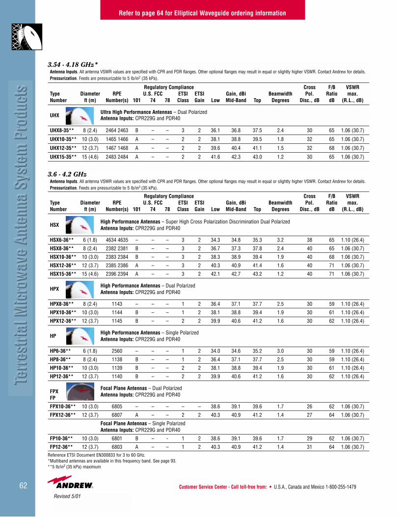
3.54 - 4.18 GHz*Antenna Inputs. All antenna VSWR values are specified with CPR and PDR flanges. Other optional flanges may result in equal or slightly higher VSWR. Contact Andrew for details.Pressurization. Feeds are pressurizable to 5 lb/in2 (35 kPa).
Regulatory Compliance Cross F/B VSWRType Diameter RPE U.S. FCC ETSI ETSI Gain, dBi Beamwidth Pol. Ratio max.Number ft (m) Number(s) 101 74 78 Class Gain Low Mid-Band Top Degrees Disc., dB dB (R.L., dB)
UHXUltra High Performance Antennas – Dual PolarizedAntenna Inputs: CPR229G and PDR40
UHX8-35** 8 (2.4) 2464 2463 B – – 3 2 36.1 36.8 37.5 2.4 30 65 1.06 (30.7)
UHX10-35** 10 (3.0) 1465 1466 A – – 2 2 38.1 38.8 39.5 1.8 32 65 1.06 (30.7)
UHX12-35** 12 (3.7) 1467 1468 A – – 2 2 39.6 40.4 41.1 1.5 32 68 1.06 (30.7)
UHX15-35** 15 (4.6) 2483 2484 A – – 2 2 41.6 42.3 43.0 1.2 30 65 1.06 (30.7)
3.6 - 4.2 GHzAntenna Inputs. All antenna VSWR values are specified with CPR and PDR flanges. Other optional flanges may result in equal or slightly higher VSWR. Contact Andrew for details.Pressurization. Feeds are pressurizable to 5 lb/in2 (35 kPa).
Regulatory Compliance Cross F/B VSWRType Diameter RPE U.S. FCC ETSI ETSI Gain, dBi Beamwidth Pol. Ratio max.Number ft (m) Number(s) 101 74 78 Class Gain Low Mid-Band Top Degrees Disc., dB dB (R.L., dB)
HSXHigh Performance Antennas – Super High Cross Polarization Discrimination Dual PolarizedAntenna Inputs: CPR229G and PDR40
HSX6-36** 6 (1.8) 4634 4635 – – – 3 2 34.3 34.8 35.3 3.2 38 65 1.10 (26.4)
HSX8-36** 8 (2.4) 2382 2381 B – – 3 2 36.7 37.3 37.8 2.4 40 65 1.06 (30.7)
HSX10-36** 10 (3.0) 2383 2384 B – – 3 2 38.3 38.9 39.4 1.9 40 68 1.06 (30.7)
HSX12-36** 12 (3.7) 2385 2386 A – – 3 2 40.3 40.9 41.4 1.6 40 71 1.06 (30.7)
HSX15-36** 15 (4.6) 2396 2394 A – – 3 2 42.1 42.7 43.2 1.2 40 71 1.06 (30.7)
HPXHigh Performance Antennas – Dual PolarizedAntenna Inputs: CPR229G and PDR40
HPX8-36** 8 (2.4) 1143 – – – 1 2 36.4 37.1 37.7 2.5 30 59 1.10 (26.4)
HPX10-36** 10 (3.0) 1144 B – – 1 2 38.1 38.8 39.4 1.9 30 61 1.10 (26.4)
HPX12-36** 12 (3.7) 1145 B – – 2 2 39.9 40.6 41.2 1.6 30 62 1.10 (26.4)
HPHigh Performance Antennas – Single PolarizedAntenna Inputs: CPR229G and PDR40
HP6-36** 6 (1.8) 2560 – – – 1 2 34.0 34.6 35.2 3.0 30 59 1.10 (26.4)
HP8-36** 8 (2.4) 1138 B – – 1 2 36.4 37.1 37.7 2.5 30 59 1.10 (26.4)
HP10-36** 10 (3.0) 1139 B – – 2 2 38.1 38.8 39.4 1.9 30 61 1.10 (26.4)
HP12-36** 12 (3.7) 1140 B – – 2 2 39.9 40.6 41.2 1.6 30 62 1.10 (26.4)
FPXFocal Plane Antennas – Dual Polarized
FPAntenna Inputs: CPR229G and PDR40
FPX10-36** 10 (3.0) 6805 – – – – – 38.6 39.1 39.6 1.7 26 62 1.06 (30.7)
FPX12-36** 12 (3.7) 6807 A – – 2 2 40.3 40.9 41.2 1.4 27 64 1.06 (30.7)
Focal Plane Antennas – Single PolarizedAntenna Inputs: CPR229G and PDR40
FP10-36** 10 (3.0) 6801 B – - 1 2 38.6 39.1 39.6 1.7 29 62 1.06 (30.7)
FP12-36** 12 (3.7) 6803 A – – 1 2 40.3 40.9 41.2 1.4 31 64 1.06 (30.7)Reference ETSI Document EN300833 for 3 to 60 GHz.*Multiband antennas are available in this frequency band. See page 93.**5 lb/in2 (35 kPa) maximum
Refer to page 64 for Elliptical Waveguide ordering information
Revised 5/01

• U.K. 0800-250055 • Australia 1800-803 219 • New Zealand 0800-441-747 Visit us at: www.andrew.com 63
3.7 - 4.2 GHz*Antenna Inputs. All antenna VSWR values are specified with CPR and PDR flanges. Other optional flanges may result in equal or slightly higher VSWR. Contact Andrew for details.Pressurization. Feeds are pressurizable to 5 lb/in2 (35 kPa).
Regulatory Compliance Cross F/B VSWRType Diameter RPE U.S. FCC ETSI ETSI Gain, dBi Beamwidth Pol. Ratio max.Number ft (m) Number(s) 101 74 78 Class Gain Low Mid-Band Top Degrees Disc., dB dB (R.L., dB)
UHXUltra High Performance AntennasAntenna Inputs: CPR229G and PDR40
UHX8-37** 8 (2.4) 1433 1434 A – – 3 2 36.8 37.4 37.6 2.4 33 66 1.06 (30.7)
UHX10-37** 10 (3.0) 1436 1435 A – – 3 2 38.5 39.1 39.5 1.8 33 67 1.06 (30.7)
UHX12-37** 12 (3.7) 1437 1438 A – – 3 2 40.4 41.0 41.2 1.5 33 73 1.06 (30.7)
UHX15-37** 15 (4.6) 1439 1440 A – – 3 2 42.1 42.7 43.1 1.2 33 73 1.06 (30.7)
PXL Standard Antennas – Dual PolarizedPL Antenna Inputs: CPR229G and PDR40
PXL10-37** 10 (3.0) 2411 B – – – – 38.7 39.3 39.8 1.8 30 45 1.06 (307)
PXL12-37** 12 (3.7) 2413 B – – 1 2 40.4 41.0 41.1 1.5 30 48 1.06 (30.7)
PXL15-37** 15 (4.6) 2415 B – – 1 2 42.1 42.7 43.0 1.2 30 52 1.06 (30.7)
Standard Antennas – Single PolarizedAntenna Inputs: CPR229G and PDR40
PL6-37** 6 (1.8) 2402 – – – – – 34.5 35.0 35.5 3.0 30 40 1.07 (29.4)
PL8-37** 8 (2.4) 2403 – – – – – 36.7 37.3 37.8 2.4 30 42 1.06 (30.7)
PL10-37** 10 (3.0) 2405 B – – – – 38.7 39.3 39.8 1.8 30 47 1.06 (30.7)
PL12-37** 12 (3.7) 2407 B – – 1 2 40.4 41.0 41.5 1.5 30 50 1.06 (30.7)
PL15-37** 15 (4.6) 2408 B – – 1 2 42.1 42.7 43.2 1.2 30 52 1.06 (30.7)
Reference ETSI Document EN300833 for 3 to 60 GHz.*Multiband antennas are available in this frequency band. See page 93.**5 lb/in2 (35 kPa) maximum
Refer to page 64 for Elliptical Waveguide ordering information
Revised 5/01

Customer Service Center - Call toll-free from: • U.S.A., Canada and Mexico 1-800-255-147964
Ordering Information for Waveguide AssembliesFrequency Waveguide Flange Connector† Flex-Twist
GHz* Type Type†† Tunable Pre-Tuned Pressure Window 2 ft (0.6 m)
Super Premium Waveguide Assemblies VSWR 1.06 (30.7)**
3.7–4.2 EWP37S CPR229G 137DET – 55001-229 F229PC0240CAPDR40 137DEMT – 223306-40 F229PH0600HA
Premium Waveguide Assemblies VSWR 1.08 (28.3)**
3.4-3.9 EWP37-34W*** CPR229G 137DET – 55001-229 F229PC0240CS3.4-3.9 EWP37-34*** PDR40 – 137DEMP-3 223306-40 F229MH0600HS3.54-4.2 EWP37-35 CPR229G 137DET 137DEP-2 55001-229 F229PC0240CA
PDR40 – 137DEMP-2 223306-40 F229MH0600HA3.52-4.2 EWP37-35W CPR229G 137DET 137DEP-2 55001-229 F229PC0240CA
PDR40 – 137DEMP-2 223306-40 F229MH0600HA3.6-4.2 EWP37-36 CPR229G 137DET – 55001-229 F229PC0240CA3.7-4.2 EWP37-37 CPR229G 137DET 137DEP-1 55001-229 F229PC0240CA
Standard Waveguide Assemblies Non-Tunable VSWR 1.15 (23.1)**
3.4–4.2 EW37 CPR229G 137DE – 55001-229 F229PC0240CSPDR40 137DEM – 223306-40 F229MH0600HS
* Contact Andrew for information on other frequency bands.** VSWR max., (R.L., dB). The indicated maximum VSWR characteristics are guaranteed for factory assemblies and are typical for field assemblies.*** VSWR 1.10 (26.4) † “Pre-tuned” connectors are for field attachment only. “Tunable” connectors ordered with factory assemblies are factory tuned. †† For detailed information on mating flanges, refer to pages 214-218.
Description Type No.
Hangers and Adapters
Hanger Kit of 10, Recommended maximum spacingfor outdoor installation is 4.5 ft (1.37 m)* 42396A-4Hardware Kit of 10, 3/8" bolts, lock washers, nuts
3/4" (19 mm) long 31769-51" (25 mm) long 31769-1
Angle Adapter Kit of 10. Stainless steel 31768ARound Member Adapter Kit of 10. Stainless steelMember Diameter, in (mm)
1-2 (25-50) 31670-12-3 (50-75) 31670-23-4 (75-100) 31670-34-5 (100-125) 31670-45-6 (125-150) 31670-5
45° Adapter Kit of 10. Galvanized steel 42334Threaded Rod Support, 3/8” rod, nuts, washers, ceiling bracket
12 in (305 mm) long, kit of 1 3177112 in (305 mm) long, kit of 5 31771-424 in (610 mm) long, kit of 1 31771-924 in (610 mm) long, kit of 5 31771-6
Tower Standoff Kit of 10. 1 in (25 mm) standoffMember Diameter, in (mm)
0.75-1.5 (20-40) 30848-51.5-3.0 (40-75) 30848-43-4 (75-100) 30848-14-5 (100-125) 30848-25-6 (125-150) 30848-3
Tower Standoff Kit of 10. 2.5 in (60 mm) standoffMember Diameter, in (mm)
3-4 (75-100) 41108A-14-5 (100-125) 41108A-25-6 (125-150) 41108A-3
* Standard conditions: 125 mph (200 km/h) survival wind velocity, 0.5 in (13 mm) radial ice. For other conditions see page 196.
Description Type No.
Other Accessories
Flaring Tool Kit for connector attachment 205869Splice 134DZGrounding Kit with factory attached, one-hole lug 204989-5Grounding Kit with factory attached, two-hole lug 241088-5Grounding Kit with field attachable crimp-on, one-hole lug 204989-25Grounding Kit with field attachable crimp-on, two-hole lug 241088-10Grounding Kit with field attachable screw-on lug 204989-35Crimping Tool to field attach lug to Grounding Kit 207270Hoisting Grip 31535Bending Tool Kit. One each E and H Plane tool EWBTK-3Connector Reattachment Kit 33544-24Wall-Roof Feed Thru 245314-37Waveguide Boot for Plates (below),
4 in (102 mm) dia. WGB4-375 in (127 mm) dia WGB5-37
Feed-Thru Plate for Boots (above)
Openings For 4 in Boots For 5 in Boots
1 204673-1 48940-11 204673-2 –2 – 48940-23 – 48940-34 204673-4 48940-46 – 48940-68 204673-8 –
Accessories – Photos and detailed descriptions on pages 194-200
Revised 5/01

• U.K. 0800-250055 • Australia 1800-803 219 • New Zealand 0800-441-747 Visit us at: www.andrew.com 65
4.4 - 5.0 GHz*Antenna Inputs. All antenna VSWR values are specified with CPR and PDR flanges. Other optional flanges may result in equal or slightly higher VSWR. Contact Andrew for details.Pressurization. Feeds are pressurizable to 10 lb/in2 (70 kPa) except LBX 5 lb/in2 (35 kPa).
Regulatory Compliance Cross F/B VSWRType Diameter RPE U.S. FCC ETSI ETSI Gain, dBi Beamwidth Pol. Ratio max.Number ft (m) Number(s) 101 74 78 Class Gain Low Mid-Band Top Degrees Disc., dB dB (R.L., dB)
HSXHigh Performance Antennas – Super High Cross Polarization DiscriminationAntenna Inputs: CPR187G and PDR48
HSX6-44 6 (1.8) 2398 2400 – – – 3 2 35.7 36.3 36.8 2.6 40 68 1.06 (30.7)
HSX8-44 8 (2.4) 2406 2404 – – – 3 2 38.2 38.8 39.3 1.9 40 70 1.06 (30.7)
HSX10-44 10 (3.0) 2410 2412 – – – 3 2 40.0 40.6 41.1 1.5 40 71 1.06 (30.7)
HSX12-44 12 (3.7) 2414 2416 – – – 3 2 41.7 42.2 42.8 1.2 40 74 1.06 (30.7)
HSX15-44 15 (4.6) 2420 2418 – – – 3 2 43.7 44.3 44.8 1.0 40 75 1.06 (30.7)
HPX High Performance Antennas – Dual PolarizedHP Antenna Inputs: CPR187G, PDR48, and UG-148C/U
HPX6-44 6 (1.8) 2558 – – – 2 2 35.8 36.3 36.8 2.5 30 60 1.06 (30.7)
HPX8-44 8 (2.4) 2544 – – – – – 38.6 39.1 39.7 1.8 30 64 1.06 (30.7)
HPX10-44 10 (3.0) 2546 – – – 2 2 39.8 40.3 40.9 1.5 30 66 1.06 (30.7)
HPX12-44 12 (3.7) 2548 – – – 2 2 41.9 42.5 43.0 1.2 30 67 1.06 (30.7)
High Performance Antennas –Single PolarizedAntenna Inputs: CPR187G, PDR48, and UG-148C/U
HP4-44 4 (1.2) 2523 – – – 2 2 30.0 32.6 33.1 3.8 30 56 1.10 (26.4)
HP6-44 6 (1.8) 2524 – – – 2 2 36.0 36.6 37.1 2.5 30 62 1.06 (30.7)
HP8-44 8 (2.4) 2527 – – – 2 2 38.7 39.3 39.8 1.8 30 65 1.06 (30.7)
HP10-44 10 (3.0) 2528 – – – 2 2 40.4 41.0 41.5 1.5 30 67 1.06 (30.7)
HP12-44 12 (3.7) 2540 – – – 2 2 42.1 42.7 43.2 1.2 30 67 1.06 (30.7)
HP15-44 15 (4.6) 2530 – – – 2 2 44.0 44.5 45.0 1.0 30 68 1.06 (30.7)
PXL Standard Antennas – Dual PolarizedPL Antenna Inputs: CPR187G, PDR48, and UG-148C/U
PXL4-44 4 (1.2) 2495 – – – – – 32.3 32.7 33.1 3.7 30 40 1.08 (28.3)
PXL6-44 6 (1.8) 2496 – – – – – 35.9 36.4 36.9 2.5 30 43 1.06 (30.7)
PXL8-44 8 (2.4) 2497 – – – – – 38.6 39.2 39.7 1.8 30 45 1.06 (30.7)
PXL10-44 10 (3.0) 2498 – – – 1 2 40.3 40.9 41.2 1.5 30 50 1.06 (30.7)
PXL12-44 12 (3.7) 2499 – – – 1 2 42.0 42.6 43.1 1.2 30 51 1.06 (30.7)
Standard Antennas – Single PolarizedAntenna Inputs: CPR187G, PDR48, and UG-148C/U
PL4-44 4 (1.2) 2551 – – – – – 32.4 33.0 33.5 3.7 30 40 1.08 (28.3)
PL6-44 6 (1.8) 2552 – – – 1 2 36.0 36.6 37.1 2.5 30 44 1.06 (30.7)
PL8-44 8 (2.4) 2553 – – – – – 38.7 39.3 39.8 1.8 30 45 1.06 (30.7)
PL10-44 10 (3.0) 2554 – – – 1 2 40.4 41.0 41.5 1.5 30 49 1.06 (30.7)
PL12-44 12 (3.7) 2556 – – – – – 42.1 42.7 43.2 1.2 30 50 1.06 (30.7)
PL15-44 15 (4.6) 2557 – – – – – 44.0 44.5 45.0 1.0 29 51 1.06 (30.7)
LBXLow Back Lobe Antennas – Dual PolarizedAntenna Input: CPR187G
Regulatory Compliance***
LBX6-44** 6 (1.8) 4636 B 35.8 36.4 36.9 2.5 33 52 1.09 (27.3)
LBX8-44** 8 (2.4) 4637 B 38.6 39.2 39.7 1.8 33 56 1.08 (28.3)
LBX10-44** 10 (3.0) 4638 B 40.1 40.7 41.2 1.5 33 62 1.08 (28.3)
LBX12-44** 12 (3.7) 4639 B 42.0 42.6 43.1 1.2 33 64 1.08 (28.3)
Reference ETSI Document EN300833 for 3 to 60 GHz.*Multiband antennas are available in this frequency band. See pages 93-94.**5 lb/in2 (35 kPa) maximum***ANATEL Brazilian Telecommunications Agency, Regulation 1286 Category
Refer to page 66 for Elliptical Waveguide ordering information
Revised 5/01

Customer Service Center - Call toll-free from: • U.S.A., Canada and Mexico 1-800-255-147966
Ordering Information for Waveguide AssembliesFrequency Waveguide Flange Connector† Flex-Twist
GHz* Type Type†† Tunable Pre-Tuned Pressure Window 2 ft (0.6 m)
Premium Waveguide Assemblies VSWR 1.07 (29.4)**
4.4–5.0 EWP43 UG-149/U††† 143DCT 143SC 55000A-187 F187PA0240BACPR187G 143DET 143SE 55001-187 F187PA0240CAPDR48 – 143SEM 223306-48 F187MH0600HA1PAR48 – 143SCM
Standard Waveguide Assemblies VSWR 1.15 (23.1)**
4.4–5.0 EW43 UG-149/U††† – 143SC 223306-48 F187MH0600HSCPR187G – 143SE 55001-187 F187PA0240CSPDR48 – 143SEMPAR48 – 143SCM
*Contact Andrew for information on other frequency bands.** VSWR max., (R.L., dB). Up to 300 ft (90 m). The indicated maximum VSWR characteristics are guaranteed for factory assemblies and are typical for field assemblies.† “Pre-tuned” connectors are for field attachment only. “Tunable” connectors ordered with factory assemblies are factory tuned. †† For detailed information on mating flanges, refer to pages 214-218. ††† Modified cover flange with gasket groove. Mates with UG choke or cover flanges.
Description Type No.
Hangers and Adapters
Hanger Kit of 10, Recommended maximum spacingfor outdoor installation is 4 ft (1.22 m)* 42396A-16Hardware Kit of 10, 3/8" bolts, lock washers, nuts
3/4" (19 mm) long 31769-51" (25 mm) long 31769-1
Angle Adapter Kit of 10. Stainless steel 31768ARound Member Adapter Kit of 10. Stainless steelMember Diameter, in (mm)
1-2 (25-50) 31670-12-3 (50-75) 31670-23-4 (75-100) 31670-34-5 (100-125) 31670-45-6 (125-150) 31670-5
45° Adapter Kit of 10. Galvanized steel 42334Threaded Rod Support, 3/8” rod, nuts, washers, ceiling bracket
12 in (305 mm) long, kit of 1 3177112 in (305 mm) long, kit of 5 31771-424 in (610 mm) long, kit of 1 31771-924 in (610 mm) long, kit of 5 31771-6
Tower Standoff Kit of 10. 1 in (25 mm) standoffMember Diameter, in (mm)
0.75-1.5 (20-40) 30848-51.5-3.0 (40-75) 30848-43-4 (75-100) 30848-14-5 (100-125) 30848-25-6 (125-150) 30848-3
* Standard conditions: 125 mph (200 km/h) survival wind velocity, 0.5 in (13 mm) radial ice. For other conditions see page 196.
Description Type No.
Hangers and Adapters
Tower Standoff Kit of 10. 2.5 in (60 mm) standoffMember Diameter, in (mm)
3-4 (75-100) 41108A-14-5 (100-125) 41108A-25-6 (125-150) 41108A-3
Other Accessories
Flaring Tool Kit for connector attachment EWFTK-43Splice 143DZGrounding Kit with factory attached, one-hole lug 204989-10Grounding Kit with field attachable crimp-on, one-hole lug 204989-28Crimping Tool to field attach lug to Grounding Kit 207270Hoisting Grip 31535Bending Tool Kit. One each E and H Plane tool EWBTK-3Connector Reattachment Kit 33544-45Wall-Roof Feed Thru 245314-43Waveguide Boot for Plates (below),
4 in (102 mm) dia. WGB4-435 in (127 mm) dia. WGB5-43
Feed-Thru Plate for Boots (above)
Openings For 4 in Boots
1 204673-11 204673-24 204673-48 204673-8
Accessories – Photos and detailed descriptions on pages 194-200
5.25 - 5.85 GHzAntenna Inputs. The standard connector is Type N Female. Contact Andrew for other options.
Pressurization. Pressurization not required.
Side F/B VSWRType Dimension Gain, dBi Beamwidth, degrees Ratio max.Number in (mm) Mid-Band Mid-Band dB (R.L., dB)
FPAFlat Panel Array Antennas – Single PolarizedAntenna Inputs: Type N Female
FPA5250D06-N 6 (150) 18.0 19.3 35 1.50 (14.0)
FPA5250D12-N 12 (300) 23.6 9.6 40 1.50 (14.0)
FPA5250D24-N 24 (600) 28.2 4.8 45 1.50 (14.0)
NEW!
Revised 7/00 & 5/01
• U.K. 0800-250055 • Australia 1800-803 219 • New Zealand 0800-441-747 Visit us at: www.andrew.com 67
5.6 - 6.2 GHz*Antenna Inputs. All antenna VSWR values are specified with CPR and PDR flanges. Other optional flanges may result in equal or slightly higher VSWR. Contact Andrew for details.Pressurization. Feeds are pressurizable to 10 lb/in2 (70 kPa).
Regulatory Compliance Cross F/B VSWRType Diameter RPE U.S. FCC ETSI ETSI Gain, dBi Beamwidth Pol. Ratio max.Number ft (m) Number(s) 101 74 78 Class Gain Low Mid-Band Top Degrees Disc., dB dB (R.L., dB)
UHXUltra High Performance Antennas – Dual PolarizationAntenna Inputs: CPR137G and PDR70
UHX10-56 10 (3.0) 1636, 1637 A – – 3 2 42.5 42.9 43.3 1.1 36 72 1.06 (30.7)UHX12-56 12 (3.7) 1638, 1639 A – – 3 2 44.0 44.5 44.9 0.9 36 73 1.06 (30.7)
HPXHigh Performance Antennas – Dual PolarizedAntenna Inputs: CPR137G and PDR70
HPX8-56 8 (2.4) 1025 B – – 3 2 40.5 41.0 41.4 1.6 30 68 1.06 (30.7)HPX10-56 10 (3.0) 1027 B – – 2 2 42.0 42.5 42.9 1.4 30 69 1.06 (30.7)HPX12-56 12 (3.7) 1030 A – – 3 2 43.8 44.2 44.7 1.0 30 71 1.06 (30.7)
5.725 - 6.425 GHzAntenna Inputs. All antenna VSWR values are specified with CPR and PDR flanges. Other optional flanges may result in equal or slightly higher VSWR. Contact Andrew for details.Pressurization. Feeds are pressurizable to 10 lb/in2 (70 kPa).
Regulatory Compliance Cross F/B VSWRType Diameter RPE U.S. FCC ETSI ETSI Gain, dBi Beamwidth Pol. Ratio max.Number ft (m) Number(s) 101 74 78 Class Gain Low Mid-Band Top Degrees Disc., dB dB (R.L., dB)
HPHigh Performance / Wide Band Antennas – Single PolarizationAntenna Inputs: CPR137G and PDR70
HP4-57W 4 (1.2) 4269 – – – 1 2 34.6 35.0 35.4 2.9 30 52 1.10 (26.4)HP6-57W 6 (1.8) 0817 – – – – – 38.0 38.5 39.0 2.0 30 60 1.06 (30.7)HP8-57W 8 (2.4) 4273 B – – 2 2 40.7 41.2 41.7 1.6 30 64 1.06 (30.7)HP10-57W 10 (3.0) 4275 A – – 2 2 42.5 42.9 43.4 1.3 30 65 1.06 (30.7)HP12-57W 12 (3.7) 4277 A – – 2 2 44.2 44.6 45.0 1.0 30 70 1.06 (30.7)HP15-57W 15 (4.6) – A – – 2 2 45.9 46.4 46.8 0.8 30 70 1.06 (30.7)
PLStandard/Wide Band Antennas – Single Polarized Standard and Low VSWRAntenna Inputs: CPR137G, PDR70, and Type N Female
P2-57W 2 (0.6) 2892 – – – 1 1 29.2 29.3 29.9 5.8 30 40 1.10 (26.4)P4-57W 4 (1.2) 4268 – – – – – 34.6 35.0 35.4 2.9 30 40 1.10 (26.4)PL6-57W 6 (1.8) 4270 B – – 1 2 38.0 38.5 39.0 2.0 30 45 1.06 (30.7)PL8-57W 8 (2.4) 4272 B – – 1 2 40.7 41.2 41.7 1.6 30 47 1.06 (30.7)PL10-57W 10 (3.0) 4274 B – – 1 2 42.5 42.9 43.4 1.3 30 50 1.06 (30.7)PL12-57W 12 (3.7) 4276 B – – 1 2 44.2 44.6 45.0 1.0 30 51 1.06 (30.7)PL15-57W 15 (4.6) – B – – 1 2 46.0 46.5 47.0 0.8 30 57 1.06 (30.7)
Reference ETSI Document EN300833 for 3 to 60 GHz.*Multiband antennas are available in this frequency band. See pages 93-94.
5.25 - 5.85 GHzAntenna Inputs. All antenna VSWR values are specified with Type N Female connectors. Other optional inputs may result in equal or slightly VSWR. Contact Andrew for details.Pressurization. Pressurization not required.
Regulatory Compliance Cross F/B VSWRType Diameter RPE U.S. FCC ETSI ETSI Gain, dBi Beamwidth Pol. Ratio max.Number ft (m) Number(s) 101 74 78 Class Gain Low Mid-Band Top Degrees Disc., dB dB (R.L., dB)
P, PXUnlicensed Radios Including Spread Spectrum, NII, and ISM – Single and Dual PolarizedAntenna Input: Type N Female
P2F-52 2 (0.6) 4528 – – – – – 29.0 29.2 29.9 5.4 30 43 1.50 (14.0)PX2F-52 2 (0.6) 4740 – – – – – 29.0 29.2 29.9 5.4 30 43 1.50 (14.0)P3F-52 3 (0.9) 4529 – – – – – 32.3 33.0 33.3 3.8 30 44 1.50 (14.0)PX3F-52 3 (0.9) 4741 – – – – – 32.3 33.0 33.3 3.8 30 44 1.50 (14.0)
Refer to page 71 for Elliptical Waveguide ordering information
Revised 5/01

Customer Service Center - Call toll-free from: • U.S.A., Canada and Mexico 1-800-255-147968
5.850 - 5.915, 6.425 - 6.930 GHzAntenna Inputs. All antenna VSWR values are specified with CPR and PDR flanges. Other optional flanges may result in equal or slightly higher VSWR. Contact Andrew for details.Pressurization. Feeds are pressurizable to 10 lb/in2 (70 kPa).
Regulatory Compliance Cross F/B VSWRType Diameter RPE U.S. FCC ETSI ETSI Gain, dBi Beamwidth Pol. Ratio max.Number ft (m) Number(s) 101 74 78 Class Gain Low Mid-Band Top Degrees Disc., dB dB (R.L., dB)
UHXUltra High Performance/Wide Band Antennas – Dual PolarizedAntenna Inputs: CPR137G and PDR70
UHX8-58W5.850-5.915 GHz**8 (2.4) 3755 3753 – – – 3 2 40.4 40.5 40.6 1.45 34 68 1.08 (28.3)6.425-6.930 GHz*** 3772 3747 A A – 3 2 41.5 41.8 42.1 1.3 34 70 1.08 (28.3)
UHX10-58W5.850-5.915 GHz**10 (3.0) 3757 3759 – – – 3 2 42.0 42.1 42.2 1.25 34 71 1.08 (28.3)6.425-6.930 GHz*** 3774 3776 A A – 3 2 43.0 43.2 43.4 1.15 34 73 1.08 (28.3)
HPXHigh Performance/Wide Band Antennas – Dual PolarizedAntenna Inputs: CPR137G and PDR70
HPX8-58W5.850-5.915 GHz**8 (2.4) 3749 – – – 2 2 40.7 40.8 40.9 1.4 32 65 1.08 (28.3)6.425-6.930 GHz*** 3761 B A – 3 2 41.7 41.9 42.2 1.4 34 67 1.08 (28.3)
HPX10-58W5.850-5.915 GHz**10 (3.0) 3751 – – – 2 2 42.6 42.7 42.8 1.2 32 68 1.08 (28.3)6.425-6.930*** 3770 B A – 2 2 43.4 43.4 43.8 1.2 34 69 1.08 (28.3)
5.925 - 6.425 GHz*Antenna Inputs. All antenna VSWR values are specified with CPR and PDR flanges. Other optional flanges may result in equal or slightly higher VSWR. Contact Andrew for details.Pressurization. Feeds are pressurizable to 10 lb/in2 (70 k Pa) except LBX Series 8 lb/in2 (56 kPa).
Regulatory Compliance Cross F/B VSWRType Diameter RPE U.S. FCC ETSI ETSI Gain, dBi Beamwidth Pol. Ratio max.Number ft (m) Number(s) 101 74 78 Class Gain Low Mid-Band Top Degrees Disc., dB dB (R.L., dB)
UHXUltra High Performance Antennas – Dual PolarizedAntenna Inputs: CPR137G and PDR70
UHX6-59 6 (1.8) 1730 1729 A – – 3 2 38.4 38.8 39.1 1.8 33 75 1.06 (30.7)
UHX8-59 8 (2.4) 1654 1653 A – – 3 2 40.9 41.3 41.6 1.4 33 77 1.06 (30.7)
UHX10-59 10 (3.0) 1667 1666 A – – 3 2 42.9 43.2 43.6 1.1 34 80 1.06 (30.7)
UHX12-59 12 (3.7) 1665 1664 A – – 3 2 44.4 44.8 45.2 0.9 35 80 1.06 (30.7)
UHX15-59 15 (4.6) 1662 1661 A – – 3 2 46.1 46.4 46.8 0.8 34 80 1.06 (30.7)
HSXHigh Performance Antennas, Super High Cross Polarization Discrimination Dual Polarized – TEGLAR Long Life Radome Included Antenna Inputs: CPR137G and PDR70
HSX6-59 6 (1.8) 2424 2422 B – – 3 2 38.4 38.8 39.1 1.8 40 72 1.07 (29.4)
HSX8-59 8 (2.4) 2428 2429 A – – 3 2 40.9 41.3 41.6 1.4 40 74 1.06
HSX10-59 10 (3.0) 2442 2440 A – – 3 2 42.5 42.9 43.2 1.1 40 76 1.06
HSX12-59 12 (3.7) 2444 2446 A – – 3 2 44.4 44.7 45.0 0.9 40 78 1.06
HSX15-59 15 (4.6) 2450 2448 A – – 3 2 46.3 46.6 46.9 0.8 40 79 1.06
HPX High Performance Antennas – Dual Polarized – Hypalon Radome IncludedHP Antenna Inputs: CPR137G and PDR70
HPX6-59 6 (1.8) 2664 B – – 3 2 38.4 38.8 39.1 1.8 30 65 1.07 (29.4)
HPX8-59 8 (2.4) 2678 A – – 3 2 40.9 41.3 41.6 1.4 30 69 1.06 (30.7)
HPX10-59 10 (3.0) 2684 A – – 2 2 42.7 43.1 43.5 1.1 30 71 1.06 (30.7)
HPX12-59 12 (3.7) 2682 A – – 2 2 44.4 44.8 45.2 0.9 30 71 1.06 (30.7)
HPX15-59 15 (4.6) 2683 A – – 2 2 46.1 46.4 46.8 0.8 30 71 1.06 (30.7)
Reference ETSI Document EN300833 for 3 to 60 GHz* Multiband antennas are available in this frequency band. See pages 93-94.** Meets Canadian DOC GL-34 Specification*** Meets Canadian DOC SRSP 306.4 Issue #3 Specification
Continued on next page
Refer to page 71 for Elliptical Waveguide ordering information
Revised 5/01

69
5.925 - 6.425 GHz*, 5.725 - 5.850 GHzRegulatory Compliance Cross F/B VSWR
Type Diameter RPE U.S. FCC ETSI ETSI Gain, dBi Beamwidth Pol. Ratio max.Number ft (m) Number(s) 101 74 78 Class Gain Low Mid-Band Top Degrees Disc., dB dB (R.L., dB)
HP High Performance Antennas - Hypalon Radome Included – Single PolarizedAntenna Inputs: CPR137G and PDR70
HP6-59 6 (1.8) 3302H A – – 2 2 38.7 38.9 39.4 1.8 30 62 1.06 (30.7)HP8-59 8 (2.4) 2670E A – – 2 2 41.1 41.5 41.9 1.4 30 66 1.06 (30.7)HP10-59 10 (3.0) 2672E A – – 2 2 42.9 43.3 43.6 1.1 30 69 1.06 (30.7)HP12-59 12 (3.7) 2673E A – – 2 2 44.7 45.0 45.2 0.9 30 71 1.06 (30.7)HP15-59 15 (4.6) 2675D A – – 2 2 46.1 46.4 46.8 0.8 30 71 1.06 (30.7)
HDXHigh Performance, Dual Beam Antennas Dual Polarized - TEGLAR Long Life Radome Included – Dual PolarizedAntenna Inputs: CPR137G and PDR70
HDX8-59 8 (2.4) 1750 1751 A – – 3 2 41.2 41.5 41.8 1.4 26 73 1.06 (30.7)1752 1753
HDX10-59 10 (3.0) 1758 1759 A – – 3 2 42.9 43.2 43.4 1.1 26 74 1.06 (30.7)1760 1761
HDX12-59 12 (3.7) 1766 1767 A – – 3 2 44.6 45.0 45.4 1.0 26 75 1.06 (30.7)1768 1769
PARX Standard Antennas - Similar to PL()-59 Series, Except Meet Category A – Dual PolarizedPAR Antenna Inputs: CPR137G and PDR70
PARX6-59**5.925-6.425 GHz 6 (1.8) 4377 A – – 1 2 37.8 37.9 38.2 1.9 30 60 1.08 (28.3)5.725-5.850 GHz 4331 – – – 1 2 37.5 37.6 37.7 2.0 30 58 1.25 (19.2)PARX8-59**5.925-6.425 GHz 8 (2.4) 4378 A – – 1 2 40.4 40.7 40.9 1.4 30 60 1.08 (28.3)5.725-5.850 GHz 4332 – – – 1 2 40.1 40.2 40.3 1.5 30 59 1.25 (19.2)PARX10-59 10 (3.0) 4379 A – – 1 2 42.7 43.1 43.3 1.1 35 60 1.06 (30.7)PARX12-59** 12 (3.7) 4380 A – – 1 2 43.3 44.7 45.1 0.9 34 60 1.06 (30.7)
Standard Antennas - Single PolarizedAntenna Inputs: CPR137G, PDR70, and UG-343B/U
PAR6-595.925-6.425 GHz 6 (1.8) 2472 A – – 1 2 38.0 38.2 38.4 1.9 30 55 1.06 (30.7)5.725-5.850 GHz 4327 – – – 1 2 37.7 37.8 37.9 2.0 30 55 1.25 (19.2)
PAR8-59**5.925-6.425 GHz 8 (2.4) 2517 A – – 1 2 40.4 40.8 41.0 1.4 30 58 1.06 (30.7)5.725-5.850 GHz 4328 – – – 1 2 40.1 40.2 40.3 1.5 30 55 1.25 (19.2)PAR10-59 10 (3.0) 1649 A – – 1 2 43.0 43.2 43.4 1.1 30 62 1.06 (30.7)PAR12-59 12 (3.7) 2366 A – – 1 2 44.2 44.6 44.9 0.9 30 63 1.06 (30.7)
PXL Standard Antennas – Dual PolarizedPL Antenna Inputs: CPR137G, PDR70, and UG-343B/U
PXL6-59 6 (1.8) 2632 – – – 1 2 38.4 38.7 39.1 1.8 30 46 1.07 (29.4)PXL8-59 8 (2.4) 2616 B – – 1 2 40.9 41.3 41.6 1.4 30 48 1.06 (30.7)PXL10-59 10 (3.0) 2618 B – – – – 42.7 43.1 43.5 1.1 30 49 1.06 (30.7)PXL12-59 12 (3.7) 2620 B – – 1 2 44.4 44.8 45.2 0.9 30 53 1.06 (30.7)PXL15-59 15 (4.6) 2642 B – – – – 46.1 46.4 46.8 0.8 30 54 1.06 (30.7)
Standard Antennas – Single PolarizedAntenna Inputs: CPR137G, PDR70, and UG-343B/U
PL4-59 4 (1.2) 2602 – – – – – 35.0 35.4 35.7 2.7 30 41 1.08 (28.3)PL6-59 6 (1.8) 2604D B – – 1 2 38.4 38.9 39.4 1.8 30 46 1.06 (30.7)PL8-59 8 (2.4) 2610D B – – 1 2 41.1 41.5 41.9 1.4 30 48 1.06 (30.7)PL10-59 10 (3.0) 2608D B – – 1 2 42.9 43.3 43.6 1.1 30 51 1.06 (30.7)PL12-59 12 (3.7) 2609D B – – 1 2 44.7 45.0 45.2 0.9 30 52 1.06 (30.7)PL15-59 15 (4.6) 2611D B – – 1 2 46.1 46.4 46.8 0.8 30 53 1.06 (30.7)
FPX Focal Plane Antennas – Dual PolarizedFP Antenna Inputs: CPR137G, PDR70, and UG-343B/U
FPX8-59 8 (2.4) 6111 B – – 1 2 40.1 40.4 40.6 1.4 27 64 1.07 (29.4)FPX10-59 10 (3.0) 6113 A – – 2 2 42.3 42.6 42.7 1.1 28 66 1.06 (30.7)FPX12-59 12 (3.7) 6115 B – – 1 2 44.0 44.4 44.5 0.9 28 68 1.06 (30.7)
Focal Plane Antennas – Single PolarizedAntenna Inputs: CPR137G and PDR70
FP8-59 8 (2.4) 6103 B – – 1 2 40.3 40.6 40.8 1.4 28 64 1.06 (30.7)FP10-59 10 (3.0) 6105 A – – 2 2 42.5 42.8 42.9 1.1 28 66 1.06 (30.7)FP12-59 12 (3.7) 6107 A – – 2 2 44.2 44.6 44.7 0.9 28 68 1.06 (30.7)
Reference ETSI Document EN300833 for 3 to 60 GHz; *Multiband antennas are available in this frequency range. See page 93-94.
**Uses focal plane type
• U.K. 0800-250055 • Australia 1800-803 219 • New Zealand 0800-441-747 Visit us at: www.andrew.com
Refer to page 71 for Elliptical Waveguide ordering information
Revised 5/01
Customer Service Center - Call toll-free from: • U.S.A., Canada and Mexico 1-800-255-147970
5.925 - 7.125 GHzAntenna Inputs. All antenna VSWR values are specified with CPR and PDR flanges. Other optional flanges may result in equal or slightly higher VSWR. Contact Andrew for details.Pressurization. Feeds are pressurizable to 10 lb/in2 (70 k Pa).
Regulatory Compliance Cross F/B VSWRType Diameter RPE U.S. FCC ETSI ETSI Gain, dBi Beamwidth Pol. Ratio max.Number ft (m) Number(s) 101 74 78 Class Gain Low Mid-Band Top Degrees Disc., dB dB (R.L., dB)
UHX Ultra High Performance/Wide Band Antennas – Dual PolarizedUHP Antenna Inputs: CPR137G and PDR70
UHX6-59W 6 (1.8) 1022 3303 A A – 3 2 37.5 38.8 39.5 1.8 36 67 1.08 (28.3)UHX8-59W 8 (2.4) 1115 1116 A A – 2 2 41.0 41.7 42.3 1.4 36 68 1.08 (28.3)UHX10-59W 10 (3.0) 1118 1117 A A – 2 2 42.5 43.2 43.8 1.2 36 71 1.08 (28.3)UHX12-59W 12 (3.7) 1119 1120 A A – 3 2 44.1 44.8 45.4 1.0 36 74 1.08 (28.3)
Ultra High Performance/Wide Band Antennas – Single PolarizedAntenna Inputs: CPR137G and PDR70
UHP6-59W 6 (1.8) 3492 3494 A B – 3 2 38.4 39.3 39.9 1.8 35 75 1.06 (30.7)UHP8-59W 8 (2.4) 3496 3506 A A – 3 2 40.9 41.9 42.2 1.5 35 78 1.06 (30.7)UHP10-59W 10 (3.0) 3498 3500 A A – 3 2 42.4 43.3 43.7 1.3 35 78 1.06 (30.7)UHP12-59W 12 (3.7) 3502 3508 A A - 3 2 44.3 45.2 45.5 1.0 35 80 1.06 (30.7)
HPHigh Performance/Wide Band AntennasAntenna Inputs: CPR137G and PDR70
HP6-59W 6 (1.8) 4713 A B – 2 2 38.7 39.4 40.2 1.8 32 66 1.06 (30.7)HP8-59W 8 (2.4) 4714 A A – 2 2 41.1 41.9 42.8 1.5 35 66 1.06 (30.7)HP10-59W 10 (3.0) 4715 A A – 2 2 42.9 43.6 44.3 1.2 33 69 1.06 (30.7)HP12-59W 12 (3.7) 4716 A A – 2 2 44.7 45.2 46.1 0.9 32 66 1.06 (30.7)HP15-59W 15 (4.6) 4717 A A – 2 2 46.1 46.8 47.6 0.8 30 71 1.06 (30.7)
PARXStandard/Wide Band Antennas – Dual PolarizedAntenna Inputs: CPR137G, PDR70, and UG-343B/U.
PARX6-59W 6 (1.8) 4371 A B – 1 2 37.8 38.3 38.7 1.8 30 59 1.12 (24.9)PARX8-59W 8 (2.4) 4372 A A – 1 2 40.4 40.7 40.9 1.6 30 60 1.10 (26.4)PARX10-59W 10 (3.0) 4373 A A – 1 2 42.7 43.3 44.0 1.1 35 60 1.15 (23.1)
PARStandard/Wide Band Antennas – Single PolarizedAntenna Inputs: CPR137G, PDR70, and UG-343B/U.
PAR6-59W+ 6 (1.8) 2480 A B – 1 2 38.0 38.7 39.0 1.8 30 59 1.08 (28.3)PAR8-59W+ 8 (2.4) 2572 A A – 1 2 40.4 41.0 41.6 1.4 30 58 1.06 (30.7)PAR10-59W 10 (3.0) 1279 A A – 1 2 43.0 43.4 43.8 1.1 30 62 1.06 (30.7)PAR12-59W 12 (3.7) 2578 A A – 1 2 44.2 44.9 45.7 0.9 30 63 1.06 (30.7)
PLStandard/Wide Band Antennas – Single PolarizedAntenna Inputs: CPR137G and PDR70.
PL6-59W 6 (1.8) 4708 B B – 1 2 38.4 39.3 40.2 1.8 35 46 1.06 (30.7)PL8-59W 8 (2.4) 4709 B A – 1 2 41.1 41.9 42.8 1.4 35 51 1.06 (30.7)PL10-59W 10 (3.0) 4710 B A – 1 2 42.9 43.6 44.3 1 33 55 1.06 (30.7)PL12-59W 12 (3.7) 4711 B A – 1 2 44.7 45.2 46.1 1 33 60 1.06 (30.7)PL15-59W 15 (4.6) 4712 B A – 1 2 46.1 46.8 47.6 0.8 30 57 1.06 (30.7)
5.925 - 6.425 GHz*Cross F/B VSWR
Type Diameter RPE Gain, dBi Beamwidth Pol. Ratio max.Number ft (m) Number(s) Regulatory Compliance** Low Mid-Band Top Degrees Disc., dB dB (R.L., dB)
LBX Low Back Lobe Antennas - Dual PolarizedAntenna Inputs: CPR137G and PDR70
LBX6-59*** 6 (1.8) 4640 B 38.3 38.7 39.0 1.8 33 54 1.07 (29.4)LBX8-59*** 8 (2.4) 4641 B 40.9 41.3 41.6 1.4 33 60 1.06 (30.7)LBX10-59*** 10 (3.0) 4642 B 42.6 43.0 43.3 1.1 33 65 1.06 (30.7)LBX12-59*** 12 (3.7) 4643 B 44.4 44.8 45.1 0.9 33 62 1.06 (30.7)
Reference ETSI Document EN300833 for 3 to 60 GHz *Multiband antennas are available in this frequency band. See pages 93-94.**ANATEL Telecommunications Agency, Regulation 1286 Category ***8 lb/in2 (56 kPa) maximum +Uses Focal plane type reflector and feed system.
Revised 5/01

• U.K. 0800-250055 • Australia 1800-803 219 • New Zealand 0800-441-747 Visit us at: www.andrew.com 71
Ordering Information for Waveguide AssembliesFrequency* Waveguide Flange Connector† Flex-Twist
GHz Type Type†† Tunable Fixed-Tuned Pressure Window 2 ft (0.6 m)
Super Premium Waveguide Assemblies VSWR 1.05 (32.3)**
5.925–6.425 EWP52S CPR159G 152DET*** – 55001-159 F159PC0240CAUG-344/U††† 252DCT*** – 55000A-137 F137PA0240BACPR137G 252DET*** – 55001-137 F137PC0240CAPDR70 252DEMT – 223306-70 F137MH0600HA
Premium Waveguide Assemblies VSWR 1.06 (30.7)**
5.6–6.2 EWP52-56 CPR159G 152DET 152SE 55001-159 F159PC0240CSUG-344/U††† 252DCT – 55000A-137 F137PA0240BGCPR137G 252DET 252SE 55001-137 F137PC0240CGPDR70 252DEMT 252SEM 223306-70 F137MH0600HG
5.725–6.425 EWP52-58 CPR159G 152DET 152SE 55001-159 F159PC0240CAUG-344/U††† 252DCT – 55000A-137 F137PA0240BDCPR137G 252DET 252SE 55001-137 F137PC0240CDPDR70 252DEMT 252SEM 223306-70 F137MH0600HD
5.925–6.425 EWP52-59 CPR159G 152DET 152SE 55001-159 F159PC0240CAUG-344/U††† 252DCT – 55000A-137 F137PA0240BACPR137G 252DET 252SE 55001-137 F137PC0240CAPDR70 252DEMT 252SEM 223306-70 F137MH0600HA
5.6-6.425 EWP52-56W CPR159G – 152SE 55001-159 F159PC0240CSCPR137G – 252SE 55001-137 F137PC0240CSPDR70 – 252SEM 223306-70 F137MH0600HS
Standard Waveguide Assemblies Non-Tunable VSWR 1.15 (23.1)**
5.60–6.425 EW52 CPR159G 152DE 152SE 55001-159 F159PC0240CSUG-344/U††† 252DC – 55000A-137 F137PA0240BSCPR137G 252DE 252SEM 55001-137 F137PC0240CS
* Contact Andrew for information on other frequency bands. ** VSWR max., (R.L., dB). Up to 300 ft (90 m). The indicated maximum VSWR characteristics are guaranteed for factory assemblies and are typical for field assemblies. *** 1.036 (35.0 dB) for lengths 150 ft (46 m) and shorter. † “Tunable” connectors ordered with factory assemblies are factory tuned. †† For detailed information on mating flanges, refer to pages 214-218.††† Modified cover flange with gasket groove. Mates with UG choke or cover flanges.
Description Type No.
Hangers and Adapters
Hanger Kit of 10, Recommended maximum spacingfor outdoor installation is 3.5 ft (1.07 m)* 42396A-8NEW! Snap-In Hanger Kit of 10. Recommended spacing for outdoor installation is 3.5 ft (1.07 m) EWSH-52Hardware Kit of 10, 3/8" bolts, lock washers, nuts
3/4" (19 mm) long 31769-51" (25 mm) long 31769-1
Angle Adapter Kit of 10. Stainless steel 31768AAngle Adapter Kit of 10. Galvanized
3/8" Hardware 242774Metric Hardware 242774-M
Round Member Adapter Kit of 10. Stainless steelMember Diameter, in (mm)
1-2 (25-50) 31670-12-3 (50-75) 31670-23-4 (75-100) 31670-34-5 (100-125) 31670-45-6 (125-150) 31670-5
45° Adapter Kit of 10. Galvanized steel 42334Threaded Rod Support, 3/8” rod, nuts, washers, ceiling bracket
12 in (305 mm) long, kit of 1 3177112 in (305 mm) long, kit of 5 31771-424 in (610 mm) long, kit of 1 31771-924 in (610 mm) long, kit of 5 31771-6
Tower Standoff Kit of 10. 1 in (25 mm) standoffMember Diameter, in (mm)
0.75-1.5 (20-40) 30848-51.5-3.0 (40-75) 30848-43-4 (75-100) 30848-14-5 (100-125) 30848-25-6 (125-150) 30848-3
* Standard conditions: 125 mph (200 km/h) survival wind velocity, 0.5 in (13 mm) radial ice. For other conditions see page 196.
Description Type No.
Tower Standoff Kit of 10. 2.5 in (60 mm) standoffMember Diameter, in (mm)
3-4 (75-100) 41108A-14-5 (100-125) 41108A-25-6 (125-150) 41108A-3
Other Accessories
Flaring Tool Kit for connector attachment EWFTK-52Splice 152DZGrounding Kit with factory attached, one-hole lug 204989-4Grounding Kit with factory attached, two-hole lug 241088-4Grounding Kit with field attachable crimp-on, one-hole lug 204989-24Grounding Kit with field attachable crimp-on, two-hole lug 241088-9Grounding Kit with field attachable screw-on lug 204989-34Crimping Tool to field attach lug to Grounding Kit 207270Hoisting Grip 24312ABending Tool Kit. One each E and H Plane tool EWBTK-2Connector Reattachment Kit 33544-38Wall-Roof Feed Thru 245314-52Waveguide Boot for Plates (below),
4 in (102 mm) dia. WGB4-525 in (127 mm) dia WGB5-52
Feed-Thru Plate for Boots (above)
Openings For 4 in Boots For 5 in Boots
1 204673-1 48940-11 204673-2 –2 – 48940-23 – 48940-34 204673-4 48940-46 – 48940-68 204673-8 –
Accessories – Photos and detailed descriptions on pages 194-200
Revised 5/01

Customer Service Center - Call toll-free from: • U.S.A., Canada and Mexico 1-800-255-147972
6.425 - 7.125 GHz, Dual Beam AntennasAntenna Inputs. All antenna VSWR values are specified with CPR flange. Other optional flanges may result in equal or slightly higher VSWR. Contact Andrew for details.Pressurization. Feeds are pressurizable to 10 lb/in2 (70 kPa).
Regulatory Compliance Cross F/B VSWRType Diameter RPE U.S. FCC ETSI ETSI Gain, dBi Beamwidth Pol. Ratio max.Number ft (m) Number(s) 101 74 78 Class Gain Low Mid-Band Top Degrees Disc., dB dB (R.L., dB)
HDH High Performance Dual-Beam (Angle Diversity) Antennas - Hypalon Radome Included – Horizontal PolarizationHDV Antenna Input: CPR137G
HDH6-65 6 (1.8) 1884 1885 B B – – – 39.4 39.7 40.0 1.9 30 60 1.08 (28.3)
HDH8-65 8 (2.4) 1893 1892 B A – – – 42.1 42.4 42.7 1.5 30 65 1.06 (30.7)
HDH10-65 10 (3.0) 1900 1901 B A – – – 43.6 43.9 44.2 1.2 26 66 1.06 (30.7)
HDH12-65 12 (3.7) 1908 1909 A A – – – 45.0 45.3 45.6 0.9 30 70 1.06 (30.7)
High Performance Dual-Beam (Angle Diversity) Antennas - Hypalon Radome Included – Vertical PolarizationAntenna Input: CPR137G
HDV6-65 6 (1.8) 1880 1881 B B – 2 2 39.4 39.7 40.0 1.9 29 65 1.08 (28.3)
HDV8-65 8 (2.4) 1888 1889 B A – – – 42.1 42.4 42.7 1.5 30 62 1.06 (30.7)
HDV10-65 10 (3.0) 1896 1897 B A – – – 43.6 43.9 44.2 1.2 30 66 1.06 (30.7)
HDV12-65 12 (3.7) 1904 1905 A A – – – 45.0 45.3 45.6 0.9 30 67 1.06 (30.7)
PDH Standard, Dual-Beam (Angle Diversity) Antennas – Horizontal PolarizationPDV Antenna Input: CPR137G
PDH6-65 6 (1.8) 1778 1779 – – – – – 39.4 39.7 40.0 1.9 30 46 1.08 (28.3)
PDH8-65 8 (2.4) 1786 1787 B B – – – 42.1 42.4 42.7 1.5 30 55 1.06 (30.7)
PDH10-65 10 (3.0) 1794 1795 B A – – – 43.6 43.9 44.2 1.2 30 60 1.06 (30.7)
PDH12-65 12 (3.7) 1743 1744 B A – – – 45.0 45.3 45.6 0.9 30 53 1.06 (30.7)
Standard, Dual-Beam (Angle Diversity) Antennas – Vertical PolarizationAntenna Input: CPR137G
PDV6-65 6 (1.8) 1774 1775 – – – – – 39.4 39.7 40.0 1.9 29 54 1.08 (28.3)
PDV8-65 8 (2.4) 1782 1783 B B – 1 2 42.1 42.4 42.7 1.5 30 55 1.06 (30.7)
PDV10-65 10 (3.0) 1790 1791 B A – – – 43.6 43.9 44.2 1.2 30 60 1.06 (30.7)
PDV12-65 12 (3.7) 1739 1740 B A – – – 45.0 45.3 45.6 0.9 30 60 1.06 (30.7)
Standard, Dual-Beam (Angle Diversity) Antennas – Vertical/Horizontal, Sum and Difference ModeAntenna Input: CPR137G
PDH8S-65 8 (2.4) 1788 1789 – – – – – 40.0 39.8 39.8 1.3 30 51 1.08 (28.3)
PDV8S-65 8 (2.4) 1784 1785 – – – – – 40.0 39.8 39.8 1.3 30 57 1.06 (30.7)
Reference ETSI Document EN300833 for 3 to 60 GHz
Refer to page 75 for Elliptical Waveguide ordering information
Revised 5/01

• U.K. 0800-250055 • Australia 1800-803 219 • New Zealand 0800-441-747 Visit us at: www.andrew.com 73
6.425 - 7.125 GHz*Antenna Inputs. All antenna VSWR values are specified with CPR and PDR flanges. Other optional flanges may result in equal or slightly higher VSWR. Contact Andrew for details.Pressurization. Feeds are pressurizable to 10 lb/in2 (70 kPa).
Regulatory Compliance Cross F/B VSWRType Diameter RPE U.S. FCC ETSI ETSI Gain, dBi Beamwidth Pol. Ratio max.Number ft (m) Number(s) 101 74 78 Class Gain Low Mid-Band Top Degrees Disc., dB dB (R.L., dB)
UHXUltra High Performance Antennas - TEGLAR Long Life Radome Included – Dual PolarizedAntenna Inputs: CPR137G and PDR70
UHX6-65 6 (1.8) 1717 1718 A B – 3 2 39.1 39.5 40.0 1.7 30 70 1.06 (30.7)
UHX8-65 8 (2.4) 2581 2584 A A – 3 2 41.6 42.0 42.4 1.3 30 76 1.06 (30.7)
UHX10-65 10 (3.0) 2582 2583 A A – 3 2 43.6 44.0 44.4 1.0 32 80 1.06 (30.7)
UHX12-65 12 (3.7) 1715 1716 A A – 3 2 45.2 45.7 46.1 0.9 38 78 1.06 (30.7)
UHX15-65 15 (4.6) 1709 1710 A A – 2 2 46.6 46.9 47.3 0.7 30 75 1.06 (30.7)
HSXHigh Performance Antennas – Dual PolarizedAntenna Inputs: CPR137G and PDR70
HSX6-64 6 (1.8) 2454 2452 A A – 3 2 39.1 39.6 40.0 1.7 40 70 1.07 (29.4)
HSX8-64 8 (2.4) 2456 2458 A A – 3 2 41.6 42.0 42.4 1.3 40 75 1.06 (30.7)
HSX10-64 10 (3.0) 2461 2459 A A – 3 2 43.2 43.6 44.0 1.0 40 77 1.06 (30.7)
HSX12-64 12 (3.7) 2470 2471 A A – 3 2 45.2 45.7 46.1 0.8 40 78 1.06 (30.7)
HSX15-64 15 (4.6) 2488 2486 A A – 3 2 46.9 47.4 47.8 0.7 40 79 1.06 (30.7)
HPXHigh Performance Antennas – Dual PolarizedAntenna Inputs: CPR137G and PDR70
HPX4-65 4 (1.2) 2649 – – – 2 2 35.4 35.9 36.3 2.7 30 58 1.08 (28.3)
HPX6-65 6 (1.8) 2794 B B – 2 2 39.1 39.5 39.9 1.7 30 64 1.07 (29.4)
HPX8-65 8 (2.4) 2654 A A – 2 2 41.6 42.0 42.4 1.3 34 68 1.06 (30.7)
HPX10-65 10 (3.0) 2655 A A – 3 2 43.6 44.0 44.4 1.0 34 70 1.06 (30.7)
HPX12-65 12 (3.7) 2656 A A – 2 2 45.0 45.4 45.9 0.8 30 71 1.06 (30.7)
HPX15-65 15 (4.6) 2657 A A – 2 2 46.6 46.9 47.3 0.7 30 71 1.06 (30.7)
High Performance Antennas – Single PolarizedAntenna Inputs: CPR137G and PDR70
HP4-65 4 (1.2) 1081 – – – 2 2 35.5 36.0 36.4 2.7 30 58 1.08 (28.3)
HP6-65 6 (1.8) 1700H A A – 2 2 39.4 39.8 40.2 1.7 30 64 1.06 (30.7)
HP8-65 8 (2.4) 2696E A A – 2 2 41.9 42.3 42.8 1.3 30 66 1.06 (30.7)
HP10-65 10 (3.0) 2690E A A – 2 2 43.6 43.9 44.3 1.0 27 70 1.06 (30.7)
HP12-65 12 (3.7) 2691E A A – 2 2 45.2 45.6 46.1 0.8 30 71 1.06 (30.7)
HP15-65 15 (4.6) 2692D A A – 2 2 46.8 47.1 47.6 0.7 30 71 1.06 (30.7)
PARX Standard Antennas – Dual PolarizedPAR Antenna Inputs: CPR137G, PDR70, and UG-343B/U
PARX6-65** 6 (1.8) 4381 A B – 1 2 38.2 38.4 38.7 1.8 30 59 1.08 (28.3)
PARX8-65** 8 (2.4) 4382 A A – 1 2 40.9 41.2 41.3 1.3 30 60 1.08 (28.3)
PARX10-65 10 (3.0) 4383 A A – 1 2 43.3 43.6 44.0 1.1 35 60 1.06 (30.7)
PARX12-65 12 (3.7) 4384 A A – 1 2 45.1 45.5 45.9 0.9 35 60 1.06 (30.7)
Standard Antennas – Single PolarizedAntenna Inputs: CPR137G, PDR70, and UG-343B/U
PAR6-65** 6 (1.8) 1290 A B – 1 2 38.7 38.8 39.0 1.8 30 59 1.06 (30.7)
PAR8-65** 8 (2.4) 2570 A A – 1 2 41.0 41.3 41.6 1.3 30 60 1.06 (30.7)
PAR10-65 10 (3.0) 1257 A A – 1 2 43.4 43.6 43.8 1.0 30 63 1.06 (30.7)
PAR12-65 12 (3.7) 2430 A A – 1 2 44.9 45.3 45.5 0.8 30 64 1.06 (30.7)Reference ETSI Document EN300833 for 3 to 60 GHz* Multiband antennas available in this frequency band. See pages 93-94.** Uses focal plane type reflector and feed system
Continued on next page
Refer to page 75 for Elliptical Waveguide ordering information
Revised 9/00 & 5/01

Customer Service Center - Call toll-free from: • U.S.A., Canada and Mexico 1-800-255-147974
6.425 - 7.125 GHz*Antenna Inputs. All antenna VSWR values are specified with CPR and PDR flanges. Other optional flanges may result in equal or slightly higher VSWR. Contact Andrew for details.Pressurization. Feeds are pressurizable to 10 lb/in2 (70 kPa), except LBX Series 8 lb/in2 (56 kPa).
Regulatory Compliance Cross F/B VSWRType Diameter RPE U.S. FCC ETSI ETSI Gain, dBi Beamwidth Pol. Ratio max.Number ft (m) Number(s) 101 74 78 Class Gain Low Mid-Band Top Degrees Disc., dB dB (R.L., dB)
PXL Standard Antennas – Dual PolarizedPL Antenna Input: CPR137G, PDR70, and UG-343B/U
PXL6-65 6 (1.8) 2634 – – – – – 39.1 39.4 39.9 1.7 30 47 1.07 (29.41)PXL8-65 8 (2.4) 2636 B A – 1 2 41.6 42.0 42.4 1.3 34 52 1.06 (30.7)PXL10-65 10 (3.0) 2638 B A – 1 2 43.6 44.0 44.4 1.0 34 58 1.06 (30.7)PXL12-65 12 (3.7) 2641 B A – 1 2 45.0 45.4 45.9 0.8 30 62 1.06 (30.7)PXL15-65 15 (4.6) 2640 B A – 1 2 46.6 46.9 47.3 0.7 30 59 1.06 (30.7)
Standard Antennas – Single Polarized; Antenna Input: CPR137G, PDR70, and UG-343B/UPL4-65 4 (1.2) 2622 – – – 1 2 35.8 36.3 36.7 2.5 30 43 1.08 (28.3)PL6-65 6 (1.8) 2624D B B – 1 2 39.3 39.8 40.2 1.7 30 47 1.06 (30.7)PL8-65 8 (2.4) 2626D B A – 1 2 41.9 42.3 42.8 1.3 30 49 1.06 (30.7)PL10-65 10 (3.0) 2628D B A – 1 2 43.6 43.9 44.3 1.0 30 52 1.06 (30.7)PL12-65 12 (3.7) 2629E B A – 1 2 45.2 45.6 46.1 0.8 30 53 1.06 (30.7)PL15-65 15 (4.6) 2630D B A – 1 2 46.8 47.1 47.6 0.7 30 54 1.06 (30.7)
FPX Focal Plane Antennas – Dual PolarizedFP Antenna Input: CPR137G and PDR70
FPX6-64 6 (1.8) 6126 B B – 1 2 38.0 38.4 38.6 1.8 28 57 1.08 (28.3)FPX8-64 8 (2.4) 6127 A A – 2 2 40.8 41.2 41.4 1.3 30 64 1.07 (29.4)FPX10-64 10 (3.0) 6129 A A – 2 2 43.0 42.4 42.8 1.0 30 66 1.06 (30.7)FPX12-64 12 (3.7) 6131 A A – 2 2 44.8 45.2 45.4 0.8 30 68 1.06 (30.7)
Focal Plane Antennas – Single Polarized; Antenna Input: CPR137G and PDR70FP6-64 6 (1.8) 6117 B B – 1 2 38.2 38.6 38.8 1.8 28 57 1.07 (29.4)FP8-64 8 (2.4) 6119 A A – 2 2 41.1 41.5 41.8 1.3 30 64 1.06 (30.7)FP10-64 10 (3.0) 6122 A B – 1 2 43.2 43.4 43.6 1.0 27 66 1.06FP12-64 12 (3.7) 6123 A A – 2 2 44.9 45.3 45.5 0.8 30 68 1.06
LBXLow Back Lobe Antennas – Dual PolarizedAntenna Input: CPR137G
Regulatory Compliance***LBX6-65** 6 (1.8) 4644 – – B – – 39.1 39.6 40.0 1.7 33 54 1.07 (30.7)LBX8-65** 8 (2.4) 4645 – – B – – 41.5 42.0 42.4 1.3 33 60 1.06 (30.7)LBX10-65** 10 (3.0) 4646 – – B – – 43.1 43.6 44.0 1.0 33 65 1.06 (30.7)LBX12-65** 12 (3.7) 4647 – – B – – 44.8 45.3 45.7 0.8 33 63 1.06 (30.7)
Reference ETSI Document EN300833 for 3 to 60 GHz*Multiband antennas available in this frequency band. See pages 93-94. **8 lb/in2 (56 kPa) maximum ***ANATEL Brazilian Telecommunications Agency, Regulation 1286 Category6.875-7.125 GHz, See PAR6-65
Revised 9/00 & 5/01
7.125 - 7.725 GHzAntenna Inputs. All antenna VSWR values are specified with CPR and PDR flanges. Other optional flanges may result in equal or slightly higher VSWR. Contact Andrew for details.Pressurization. Feeds are pressurizable to 10 lb/in2 (70 kPa) except LBX Series 8 lb/in2 (56 kPa). ValuLine® Antennas. See page 127.
Regulatory Compliance Cross F/B VSWRType Diameter RPE U.S. FCC ETSI ETSI Gain, dBi Beamwidth Pol. Ratio max.Number ft (m) Number(s) 101 74 78 Class Gain Low Mid-Band Top Degrees Disc., dB dB (R.L., dB)
FPX Focal Plane Antennas – Dual PolarizedFP Antenna Input: PDR70
FPX6-71 6 (1.8) 6141 – – – 1 2 38.8 39.2 39.5 1.5 25 58 1.08 (28.3)FPX8-71 8 (2.4) 6143 – – – 2 2 41.8 42.1 42.3 1.1 26 65 1.07 (29.4)FPX10-71 10 (3.0) 6145 – – – 2 2 43.9 44.2 44.3 0.9 26 67 1.06 (30.7)FPX12-71 12 (3.7) 6147 – – – 2 2 45.5 45.9 46.0 0.7 28 69 1.06 (30.7)
Focal Plane Antennas – Single Polarized; Antenna Input: PDR70FP4-71 4 (1.2) 6132 – – – 1 2 34.9 35.2 35.4 2.2 25 52 1.10 (26.4)FP6-71 6 (1.8) 6133 – – – 1 2 38.8 39.2 39.5 1.5 25 58 1.07 (29.4)FP8-71 8 (2.4) 6135 – – – 2 2 42.0 42.3 42.4 1.1 26 65 1.06 (30.7)FP10-71 10 (3.0) 6137 – – – 2 2 44.1 44.4 44.5 0.9 26 67 1.04 (34.2)FP12-71 12 (3.7) 6139 – – – 2 2 45.7 46.1 46.2 0.7 28 69 1.04 (34.2)

• U.K. 0800-250055 • Australia 1800-803 219 • New Zealand 0800-441-747 Visit us at: www.andrew.com 75
Ordering Information for Waveguide AssembliesFrequency* Waveguide Flange Connector† Flex-Twist
GHz Type Type†† Tunable Fixed-Tuned Pressure Window 2 ft (0.6 m)
Super Premium Waveguide Assemblies VSWR 1.05 (32.3)**
6.425–7.125 EWP63S UG-344/U††† 163DCT – 55000A-137 F137PA0240BBCPR137G 163DET – 55001-137 F137PC0240CBPDR70 – 163SEM 223306-70 F137MH0600HB
Premium Waveguide Assemblies VSWR 1.06 (30.7)**
5.925–6.575 EWP63-59 UG-344/U††† 163DCT – 55000A-137 F137PA0240BA***CPR137G 163DET 163SE 55001-137 F137PC0240CA***PDR70 – 163SEM 223306-70 F137MH0600HA***
5.800–7.125 EWP63-59W UG-344/U††† 163DCT – 55000A-137 F137PA0240BA***CPR137G 163DET 163SE 55001-137 F137PC0240CA***PDR70 – 163SEM 223306-70 F137MH0600HA***
VSWR 1.05 (32.3)*
6.525–6.875 EWP63-65N UG-344/U††† 163DCT – 55000A-137 F137PA0240BBCPR137G 163DET 163SE 55001-137 F137PC0240CBPDR70 – 163SEM 223306-70 F137MH0600HB
VSWR 1.06 (30.7)**
6.425–7.125 EWP63-65 UG-344/U††† 163DCT – 55000A-137 F137PA0240BBCPR137G 163DET 163SE 55001-137 F137PC0240CBPDR70 – 163SEM 223306-70 F137MH0600HB
Standard Waveguide Assemblies Non-Tunable VSWR 1.15 (23.1)**
5.925–7.125 EW63 UG-344/U††† 163DC – 55000A-137 F137PA0240BSCPR137G 163DE 163SE 55001-137 F137PC0240CBPDR70 – 163SEM 223306-70 F137MH0600HS
* Contact Andrew for information on other frequency bands. ** VSWR max., (R.L., dB). Up to 300 ft (90 m). The indicated maximum VSWR characteristics are guaranteed for factory assemblies and are typical for field assemblies. *** Low VSWR guaranteed for 5.925 to 6.425 GHz, nominal for 5.925 to 6.575 GHz. † “Tunable” connectors ordered with factory assemblies are factory tuned. †† For detailed information on mating flanges, refer to pages 214-218. ††† Modified coverflange with gasket groove. Mates with UG choke or cover flanges.
Description Type No.
Hangers and Adapters
Hanger Kit of 10, Recommended maximum spacingfor outdoor installation is 3 ft (0.91 m)* 42396A-7NEW! Snap-In Hanger Kit of 10. Recommended spacing for outdoor installation is 3.5 ft (1.07 m) EWSH-63Hardware Kit of 10, 3/8" bolts, lock washers, nuts
3/4" (19 mm) long 31769-51" (25 mm) long 31769-1
Angle Adapter Kit of 10. Stainless steel 31768AAngle Adapter Kit of 10. Galvanized
3/8" Hardware 242774Metric Hardware 242774-M
Round Member Adapter Kit of 10. Stainless steelMember Diameter, in (mm)
1-2 (25-50) 31670-12-3 (50-75) 31670-23-4 (75-100) 31670-34-5 (100-125) 31670-45-6 (125-150) 31670-5
45° Adapter Kit of 10. Galvanized steel 42334Threaded Rod Support, 3/8” rod, nuts, washers, ceiling bracket
12 in (305 mm) long, kit of 1 3177112 in (305 mm) long, kit of 5 31771-424 in (610 mm) long, kit of 1 31771-924 in (610 mm) long, kit of 5 31771-6
Tower Standoff Kit of 10. 1 in (25 mm) standoffMember Diameter, in (mm)
0.75-1.5 (20-40) 30848-51.5-3.0 (40-75) 30848-43-4 (75-100) 30848-14-5 (100-125) 30848-25-6 (125-150) 30848-3
* Standard conditions: 125 mph (200 km/h) survival wind velocity, 0.5 in (13 mm) radial ice. For other conditions see page 196.
Description Type No.
Tower Standoff Kit of 10. 2.5 in (60 mm) standoffMember Diameter, in (mm)
3-4 (75-100) 41108A-14-5 (100-125) 41108A-25-6 (125-150) 41108A-3
Other Accessories
Flaring Tool Kit for connector attachment EWFTK-63Splice 163DZGrounding Kit with factory attached, one-hole lug 204989-4Grounding Kit with factory attached, two-hole lug 241088-4Grounding Kit with field attachable crimp-on, one-hole lug 204989-24Grounding Kit with field attachable crimp-on, two-hole lug 241088-9Grounding Kit with field attachable screw-on lug 204989-34Crimping Tool to field attach lug to Grounding Kit 207270Hoisting Grip 24312ABending Tool Kit. One each E and H Plane tool EWBTK-2Connector Reattachment Kit 33544-33Wall-Roof Feed Thru 245314-63Waveguide Boot for Plates (below),
4 in (102 mm) dia. WGB4-635 in (127 mm) dia WGB5-63
Feed-Thru Plate for Boots (above)
Openings For 4 in Boots For 5 in Boots
1 204673-1 48940-11 204673-2 –2 – 48940-23 – 48940-34 204673-4 48940-46 – 48940-68 204673-8 –
Accessories – Photos and detailed descriptions on pages 194-200
Revised 5/01
Customer Service Center - Call toll-free from: • U.S.A., Canada and Mexico 1-800-255-147976
7.125 - 7.750 GHzAntenna Inputs. All antenna VSWR values are specified with CPR and PDR flanges. Other optional flanges may result in equal or slightly higher VSWR. Contact Andrew for details.Pressurization. Feeds are pressurizable to 10 lb/in2 (70 kPa).ValuLine® Antennas. See page 127.
Regulatory Compliance Cross F/B VSWRType Diameter RPE U.S. FCC ETSI ETSI Gain, dBi Beamwidth Pol. Ratio max.Number ft (m) Number(s) 101 74 78 Class Gain Low Mid-Band Top Degrees Disc., dB dB (R.L., dB)
HPX High Performance Antennas – Dual PolarizedHP Antenna Inputs: CPR137G, PDR70, and UG-343B/U
HPX4-70 4 (1.2) 2862 – – – 2 2 36.0 36.4 36.7 2.3 26 61 1.08 (28.3)
HPX6-70 6 (1.8) 2816 – – – 2 2 40.0 40.4 40.7 1.5 25 65 1.07 (29.4)
HPX8-70 8 (2.4) 2826 – – – 2 2 42.4 42.9 43.2 1.1 30 67 1.06 (30.7)
HPX10-70 10 (3.0) 2754 – – – 2 2 44.5 44.8 45.0 0.9 30 70 1.06 (30.7)
HPX12-70 12 (3.7) 2758 – – – 1 2 45.7 46.1 46.4 0.8 28 71 1.06 (30.7)
HPX15-70 15 (4.6) 2782 – – – 2 2 47.3 47.7 48.0 0.7 32 72 1.06 (30.7)
High Performance Antennas – Single PolarizedAntenna Inputs: CPR137G, PDR70, and UG-343B/U
HP6-70 6 (1.8) 2796 – – – 2 2 40.1 40.5 40.9 1.5 28 65 1.06 (30.7)
HP8-70 8 (2.4) 2751 – – – 2 2 42.6 43.0 43.3 1.1 30 67 1.06 (30.7)
HP10-70 10 (3.0) 2753 – – – 2 2 44.3 44.7 45.0 0.9 30 70 1.06 (30.7)
HP12-70 12 (3.7) 2756 – – – 2 2 46.3 46.7 47.1 0.7 30 71 1.06 (30.7)
HP15-70 15 (4.6) 2757 – – – 2 2 47.4 48.1 48.4 0.6 30 71 1.06 (30.7)
PXL Standard Antennas – Dual PolarizedPL Antenna Inputs: CPR137G, PDR70, and UG-343B/U
PXL6-70 6 (1.8) 2740 – – – 1 2 40.0 40.4 40.7 1.5 30 48 1.07 (29.4)
PXL8-70 8 (2.4) 2828 – – – 1 2 42.4 42.9 43.2 1.1 30 50 1.06 (30.7)
PXL10-70 10 (3.0) 2663 – – – 1 2 44.5 44.8 45.0 0.9 30 52 1.06 (30.7)
PXL12-70 12 (3.7) 2752 – – – 1 2 45.7 46.1 46.4 0.7 30 54 1.06 (30.7)
Standard Antennas – Single PolarizedAntenna Inputs: CPR137G, PDR70, and UG-343B/U
PL4-70 4 (1.2) 2736 – – – 1 2 36.7 37.0 37.3 2.2 30 46 1.06 (30.7)
PL6-70 6 (1.8) 2658 – – – 1 2 40.1 40.5 40.9 1.5 30 48 1.06 (30.7)
PL8-70 8 (2.4) 2659 – – – 1 2 42.6 43.0 43.3 1.1 30 50 1.06 (30.7)
PL10-70 10 (3.0) 2660 – – – 1 2 44.3 44.7 45.0 0.9 30 52 1.06 (30.7)
PL12-70 12 (3.7) 2662 – – – 1 2 46.3 46.7 47.1 0.7 30 54 1.06 (30.7)
PL15-70 15 (4.6) 2745 – – – 1 2 47.7 48.1 48.4 0.6 30 55 1.06 (30.7)
7.125 - 7.750 GHzAntenna Inputs. All antenna VSWR values are specified with CPR and PDR flanges. Other optional flanges may result in equal or slightly higher VSWR. Contact Andrew for details.Pressurization. Feeds are pressurizable to 10 lb/in2 (70 kPa).ValuLine Antennas. See page 127.
Regulatory Compliance Cross F/B VSWRType Diameter RPE U.S. FCC ETSI ETSI Gain, dBi Beamwidth Pol. Ratio max.Number ft (m) Number(s) 101 74 78 Class Gain Low Mid-Band Top Degrees Disc., dB dB (R.L., dB)
HSXHigh Performance Antennas - Super High Cross Polarization Discrimination – Dual PolarizationAntenna Inputs: CPR112G, PDR84, and UG-52B/U
HSX4-71 4 (1.2) 1548 1543 – – – 3 2 36.4 36.7 37.0 2.3 40 64 1.08 (28.3)
HSX6-71 6 (1.8) 1550 1554 – – – 3 2 40.0 40.3 40.6 1.5 40 72 1.08 (28.3)
HSX8-71 8 (2.4) 1556 1566 – – – 3 2 42.3 42.6 42.9 1.2 40 73 1.06 (30.7)
HSX10-71 10 (3.0) 1624 1622 – – – 3 2 43.9 44.2 44.4 1.0 40 75 1.06 (30.7)
HSX12-71 12 (3.7) 1626 1628 – – – 3 2 46.1 46.5 46.9 0.8 40 78 1.06 (30.7)
HSX15-71 15 (4.6) 1852 1858 – – – 3 2 47.7 48.1 48.5 0.6 40 78 1.06 (30.7)
Reference ETSI Document EN300833 for 3 to 60 GHz Continued on next page
Refer to page 78 for Elliptical Waveguide ordering information
Revised 9/00 & 5/01
• U.K. 0800-250055 • Australia 1800-803 219 • New Zealand 0800-441-747 Visit us at: www.andrew.com 77
7.125 - 7.750 GHzAntenna Inputs. All antenna VSWR values are specified with CPR and PDR flanges. Other optional flanges may result in equal or slightly higher VSWR. Contact Andrew for details.Pressurization. Feeds are pressurizable to 10 lb/in2 (70 kPa) except LBX Series 8 lb/in2 (56 kPa).ValuLine® Antennas. See page 127.
Regulatory Compliance Cross F/B VSWRType Diameter RPE U.S. FCC ETSI ETSI Gain, dBi Beamwidth Pol. Ratio max.Number ft (m) Number(s) 101 74 78 Class Gain Low Mid-Band Top Degrees Disc., dB dB (R.L., dB)
HPX High Performance Antennas – Dual PolarizationHP Antenna Inputs: CPR112G and PDR84
HPX6-71 6 (1.8) 3771 – – – 2 2 39.5 39.9 40.2 1.6 30 66 1.06 (30.7)
HPX8-71 8 (2.4) 2775 – – – 2 2 42.1 42.5 42.8 0.9 30 67 1.06 (30.7)
High Performance Antennas – Single Polarized Antenna Inputs: CPR112G, PDR84, and UG-52B/U
HP4-71 4 (1.2) 2866 – – – 2 2 35.8 36.2 36.5 2.4 28 62 1.08 (28.3)
HP6-71 6 (1.8) 2800 – – – 3 2 39.7 40.0 40.3 1.5 30 66 1.06 (30.7)
HP8-71 8 (2.4) 2770 – – – 3 2 42.3 42.5 42.9 1.1 30 68 1.06 (30.7)
HP10-71 10 (3.0) 2772 – – – 3 2 44.1 44.5 44.8 0.9 28 70 1.06 (30.7)
HP12-71 12 (3.7) 2774 – – – 3 2 45.6 46.0 46.3 0.7 30 71 1.06 (30.7)
HP15-71 15 (4.6) 2783 – – – 2 2 47.5 47.8 48.2 0.6 30 71 1.06 (30.7)
PL Standard Antennas – Single Polarized Low VSWRAntenna Inputs: CPR112G, PDR84, and UG-52B/U
PL4-71 4 (1.2) 3718 – – – 1 2 36.2 36.5 36.8 2.2 30 45 1.08 (28.3)
PL6-71 6 (1.8) 2704 – – – 1 2 39.7 40.0 40.3 1.5 30 48 1.06 (30.7)
PL8-71 8 (2.4) 2700 – – – 1 2 42.3 42.5 42.9 1.1 30 50 1.06 (30.7)
PL10-71 10 (3.0) 2699 – – – 1 2 44.1 44.5 44.8 0.9 30 52 1.06 (30.7)
PL12-71 12 (3.7) 3710 – – – 1 2 45.6 46.0 46.3 0.7 30 54 1.06 (30.7)
PL15-71 15 (4.6) 2726 – – – 1 2 47.5 47.8 48.2 0.6 30 57 1.06 (30.7)
LBXLow Back Lobe Antennas – Dual PolarizedAntenna Inputs: CPR137G and PDR70
Regulatory Compliance**
LBX6-71* 6 (1.8) 4648 – – B – – 40.0 40.4 40.7 1.5 33 55 1.07 (29.4)
LBX8-71* 8 (2.4) 4649 – – B – – 42.5 42.9 43.2 1.1 33 60 1.06 (30.7)
LBX10-71* 10 (3.0) 4650 – – B – – 44.4 44.8 45.1 0.9 33 66 1.06 (30.7)
LBX12-71* 12 (3.7) 4651 – – B – – 45.7 46.1 46.4 0.7 33 64 1.06 (30.7)
Reference ETSI Document EN300833 for 3 to 60 GHz*8 lb/in2 (56 kPa) maximum**ANATEL Brazilian Telecommunications Agency, Regulation 1286 Category
Refer to page 78 for Elliptical Waveguide ordering information
Revised 9/00 & 5/01
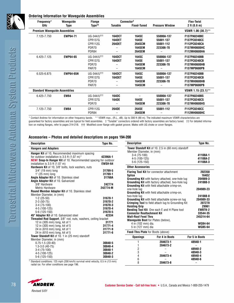
Customer Service Center - Call toll-free from: • U.S.A., Canada and Mexico 1-800-255-147978
Ordering Information for Waveguide AssembliesFrequency* Waveguide Flange Connector† Flex-Twist
GHz Type Type†† Tunable Fixed-Tuned Pressure Window 2 ft (0.6 m)
Premium Waveguide Assemblies VSWR 1.06 (30.7)**
7.125-7.750 EWP64-71 UG-344/U††† 164DCT 164SC 55000A-137 F137PA0240BCCPR137G 164DET 164SE 55001-137 F137PC0240CCCPR112G 264DET 264SCM 55001-112 F112PC0240CAPDR70 – 164SEM 223306-70 F137MH0600HCPDR84 – 264SEM – F112MH0600HA
6.425-7.125 EWP64-65 UG-344/U††† 164DCT 164SC 55000A-137 F137PA0240BBCPR137G 164DET 164SE 55001-137 F137PC0240CBPDR70 – 164SEM 223306-70 F137MH0600HBPAR70 – 164SCM – F137MP0600PB
6.525-6.875 EWP64-65N UG-344/U††† 164DCT 164SC 55000A-137 F137PA0240BBCPR137G 164DET 164SE 55001-137 F137PC0240CBPDR70 – 164SEM 223306-70 F137MH0600HBPAR70 – 164SCM – F137MP0600PB
Standard Waveguide Assemblies VSWR 1.15 (23.1)**
6.425-7.750 EW64 UG-344/U††† 164DC – 55000A-137 F137PA0240BSCPR137G 164DE 164SE 55001-137 F137PC0240CSPDR70 – 164SEM 223306-70 F137MH0600HS
7.125-7.750 EW64 CPR112G 264DE 264SE 55001-112 F112PC0240CCPDR84 – 264SEM – F112MH0600HC
* Contact Andrew for information on other frequency bands. ** VSWR max., (R.L., dB). Up to 300 ft (90 m). The indicated maximum VSWR characteristics are guaranteed for factory assemblies and are typical for field assemblies. † “Tunable” connectors ordered with factory assemblies are factory tuned. †† For detailed informa-tion on mating flanges, refer to pages 214-218. ††† Modified cover flange with gasket groove. Mates with UG choke or cover flanges.
Description Type No.
Hangers and Adapters
Hanger Kit of 10, Recommended maximum spacingfor outdoor installation is 3.5 ft (1.07 m)* 42396A-1NEW! Snap-In Hanger Kit of 10. Recommended spacing for outdoor installation is 3.5 ft (1.07 m) EWSH-64Hardware Kit of 10, 3/8" bolts, lock washers, nuts
3/4" (19 mm) long 31769-51" (25 mm) long 31769-1
Angle Adapter Kit of 10. Stainless steel 31768AAngle Adapter Kit of 10. Galvanized
3/8" Hardware 242774Metric Hardware 242774-M
Round Member Adapter Kit of 10. Stainless steelMember Diameter, in (mm)
1-2 (25-50) 31670-12-3 (50-75) 31670-23-4 (75-100) 31670-34-5 (100-125) 31670-45-6 (125-150) 31670-5
45° Adapter Kit of 10. Galvanized steel 42334Threaded Rod Support, 3/8” rod, nuts, washers, ceiling bracket
12 in (305 mm) long, kit of 1 3177112 in (305 mm) long, kit of 5 31771-424 in (610 mm) long, kit of 1 31771-924 in (610 mm) long, kit of 5 31771-6
Tower Standoff Kit of 10. 1 in (25 mm) standoffMember Diameter, in (mm)
0.75-1.5 (20-40) 30848-51.5-3.0 (40-75) 30848-43-4 (75-100) 30848-14-5 (100-125) 30848-25-6 (125-150) 30848-3
* Standard conditions: 125 mph (200 km/h) survival wind velocity, 0.5 in (13 mm) radial ice. For other conditions see page 196.
Description Type No.
Tower Standoff Kit of 10. 2.5 in (60 mm) standoffMember Diameter, in (mm)
3-4 (75-100) 41108A-14-5 (100-125) 41108A-25-6 (125-150) 41108A-3
Other Accessories
Flaring Tool Kit for connector attachment 202358Splice 164DZGrounding Kit with factory attached, one-hole lug 204989-3Grounding Kit with factory attached, two-hole lug 241088-3Grounding Kit with field attachable crimp-on, one-hole lug 204989-23Grounding Kit with field attachable crimp-on, two-hole lug 241088-8Grounding Kit with field attachable screw-on lug 204989-33Crimping Tool to field attach lug to Grounding Kit 207270Hoisting Grip 29961Bending Tool Kit. One each E and H Plane tool EWBTK-2Connector Reattachment Kit 33544-35Wall-Roof Feed Thru 245314-64Waveguide Boot for Plates (below),
4 in (102 mm) dia. WGB4-645 in (127 mm) dia WGB5-64
Feed-Thru Plate for Boots (above)
Openings For 4 in Boots For 5 in Boots
1 204673-1 48940-11 204673-2 –2 – 48940-23 – 48940-34 204673-4 48940-46 – 48940-68 204673-8 –
Accessories – Photos and detailed descriptions on pages 194-200
Revised 5/01

• U.K. 0800-250055 • Australia 1800-803 219 • New Zealand 0800-441-747 Visit us at: www.andrew.com 79
7.125 - 8.400 GHzAntenna Inputs. All antenna VSWR values are specified with CPR and PDR flanges. Other optional flanges may result in equal or slightly higher VSWR. Contact Andrew for details.Pressurization. Feeds are pressurizable to 10 lb/in2 (70 kPa).ValuLine® Antennas. See page 127.
Regulatory Compliance Cross F/B VSWRType Diameter RPE U.S. FCC ETSI ETSI Gain, dBi Beamwidth Pol. Ratio max.Number ft (m) Number(s) 101 74 78 Class Gain Low Mid-Band Top Degrees Disc., dB dB (R.L., dB)
HPXHigh Performance/Wide Band Antennas – Dual PolarizationAntenna Inputs: CPR112G and PDR84
HPX6-71W 6 (1.8) 2860 – – – 2 2 39.6 40.4 41.0 1.5 30 65 1.15 (23.1)
HPX8-71W 8 (2.4) 2825 – – – 2 2 42.1 42.9 43.5 1.2 30 67 1.10 (26.4)
HPX10-71W 10 (3.0) 2864 – – – 2 2 44.1 44.9 45.5 0.9 30 70 1.10 (26.4)
HPX12-71W 12 (3.7) 1009 – – – 2 2 46.1 46.7 47.5 0.8 30 70 1.10 (26.4)
HPX15-71W 15 (4.6) 697 – – – 2 2 47.9 48.6 49.4 0.7 30 65 1.10 (26.4)
7.125 - 8.5 GHzAntenna Inputs. All antenna VSWR values are specified with CPR and PDR flanges. Other optional flanges may result in equal or slightly higher VSWR. Contact Andrew for details.Pressurization. Feeds are pressurizable to 10 lb/in2 (70 kPa).ValuLine® Antennas. See page 127.
Regulatory Compliance Cross F/B VSWRType Diameter RPE U.S. FCC ETSI ETSI Gain, dBi Beamwidth Pol. Ratio max.Number ft (m) Number(s) 101 74 78 Class Gain Low Mid-Band Top Degrees Disc., dB dB (R.L., dB)
HPHigh Performance/Wide Band Antennas – Single PolarizedAntenna Inputs: CPR112G and PDR84
HP6-71W 6 (1.8) 2818 – – – 3 2 39.7 40.3 41.1 1.5 30 66 1.06 (30.7)
HP8-71W 8 (2.4) 2820 – – – 2 2 42.3 42.9 43.6 1.1 30 68 1.06 (30.7)
HP10-71W 10 (3.0) 2821 – – – 2 2 44.0 44.8 45.5 0.9 30 70 1.06 (30.7)
HP12-71W 12 (3.7) 2822 – – – 2 2 46.2 46.8 47.6 0.7 30 71 1.06 (30.7)
PL Standard/Wide Band Antennas – Standard and Low VSWRP Antenna Inputs: CPR112G and PDR84
PL6-71W 6 (1.8) 3703 – – – 1 2 39.7 40.3 41.1 1.5 30 48 1.10 (26.4)
PL8-71W 8 (2.4) 1271 – – – 1 2 42.3 42.9 43.6 1.1 30 52 1.10 (26.4)
PL10-71W 10 (3.0) 1273 – – – 1 2 44.0 44.8 45.5 0.9 30 55 1.10 (26.4)
PL12-71W 12 (3.7) 1275 – – – 1 2 45.6 46.3 47.1 0.7 30 58 1.10 (26.4)
PL15-71W 15 (4.6) 2710 – – – 1 2 47.5 48.2 48.9 0.6 30 57 1.10 (26.4)
Reference ETSI Document EN300833 for 3 to 60 GHz
Refer to page 84 for Elliptical Waveguide ordering information
Revised 7/00 & 5/01

Customer Service Center - Call toll-free from: • U.S.A., Canada and Mexico 1-800-255-147980
7.425 - 7.900 GHzAntenna Inputs. All antenna VSWR values are specified with CPR and PDR flanges. Other optional flanges may result in equal or slightly higher VSWR. Contact Andrew for details.Pressurization. Feeds are pressurizable to 10 lb/in2 (70 kPa).ValuLine® Antennas. See page 127.
Regulatory Compliance Cross F/B VSWRType Diameter RPE U.S. FCC ETSI ETSI Gain, dBi Beamwidth Pol. Ratio max.Number ft (m) Number(s) 101 74 78 Class Gain Low Mid-Band Top Degrees Disc., dB dB (R.L., dB)
HSXHigh Performance Antennas - Super High Cross Polarization Discrimination – Dual PolarizedAntenna Inputs: CPR112G and PDR84
HSX4-74 4 (1.2) 2157 2156 – – – 3 2 36.7 37.0 37.3 2.3 40 64 1.08 (28.3)HSX6-74 6 (1.8) 1860 1864 – – – 3 2 40.3 40.6 40.9 1.5 40 67 1.08 (28.3)HSX8-74 8 (2.4) 1865 1866 – – – 3 2 42.6 42.9 43.2 1.1 40 74 1.06 (30.7)HSX10-74 10 (3.0) 1913 1912 – – – 3 2 44.0 44.3 44.6 0.9 40 75 1.06 (30.7)HSX12-74 12 (3.7) 1914 1916 – – – 3 2 46.5 46.8 47.0 0.8 40 78 1.06 (30.7)HSX15-74 15 (4.6) 1918 1920 – – – 3 2 48.0 48.3 48.6 0.6 40 78 1.06 (30.7)
HPX High Performance Antennas – Dual PolarizedHP Antenna Inputs: CPR112G and PDR84
HPX4-74 4 (1.2) 3712 – – – 3 2 37.1 37.4 37.6 2.5 32 63 1.10 (26.4)HPX6-74 6 (1.8) 3697 – – – 3 2 40.5 40.8 41.1 1.5 32 67 1.06 (30.7)HPX8-74 8 (2.4) 3699 – – – 3 2 42.9 43.1 43.4 1.2 32 70 1.06 (30.7)HPX10-74 10 (3.0) 3695 – – – 2 2 44.3 44.7 45.0 1.1 30 68 1.06 (30.7)
High Performance Antennas – Single PolarizedAntenna Inputs: CPR112G and PDR84
HP4-74 4 (1.2) 4112 – – – 2 2 36.5 36.7 37.0 2.3 32 61 1.06 (30.7)HP6-74 6 (1.8) 3691 – – – 2 2 40.1 40.4 40.6 1.5 32 64 1.06 (30.7)HP8-74 8 (2.4) 3694 – – – 3 2 42.5 42.8 43.0 1.2 32 70 1.04 (34.2)HP10-74 10 (3.0) 2792 – – – 3 2 43.8 44.0 44.2 1.0 32 70 1.04 (34.2)
7.725 - 8.275 GHz*Antenna Inputs. All antenna VSWR values are specified with CPR and PDR flanges. Other optional flanges may result in equal or slightly higher VSWR. Contact Andrew for details.Pressurization. Feeds are pressurizable to 10 lb/in2 (70 kPa).ValuLine® Antennas. See page 127.
Regulatory Compliance Cross F/B VSWRType Diameter RPE U.S. FCC ETSI ETSI Gain, dBi Beamwidth Pol. Ratio max.Number ft (m) Number(s) 101 74 78 Class Gain Low Mid-Band Top Degrees Disc., dB dB (R.L., dB)
UHXUltra High Performance Antennas – Dual PolarizedAntenna Inputs: CPR112G and PDR84
UHX6-77 6 (1.8) 2874 2875 – – – 3 2 40.5 41.0 41.2 1.5 30 67 1.06 (30.7)
UHX8-77 8 (2.4) 2833 2834 – – – 2 2 43.1 43.5 43.7 1.1 30 68 1.06 (30.7)
UHX10-77 10 (3.0) 2835 2836 – – – 2 2 44.9 45.2 45.4 0.9 30 70 1.06 (30.7)
UHX12-77 12 (3.7) 2838 2837 – – – 3 2 46.4 46.7 46.9 0.7 30 75 1.06 (30.7)
UHX15-77 15 (4.6) 2839 2840 – – – 2 2 48.4 48.7 48.9 0.6 30 70 1.06 (30.7)
HSXHigh Performance Antennas - Super High Cross Polarization Discrimination – Dual PolarizedAntenna Inputs: CPR112G and PDR84
HSX4-77 4 (1.2) 2588 2589 – – – 3 2 37.0 37.2 37.5 2.3 40 64 1.08 (28.3)
HSX6-77 6 (1.8) 1922 1924 – – – 3 2 40.7 41.0 41.4 1.5 40 67 1.08 (28.3)
HSX8-77 8 (2.4) 1929 1930 – – – 3 2 43.2 43.5 43.8 1.1 40 77 1.06 (30.7)
HSX10-77 10 (3.0) 1966 1967 – – – 3 2 44.8 45.2 45.6 0.9 40 79 1.06 (30.7)
HSX12-77 12 (3.7) 1968 1969 – – – 3 2 46.4 46.7 47.0 0.7 40 79 1.06 (30.7)
HSX15-77 15 (4.6) 1960 1962 – – – – – 48.3 48.6 48.8 0.6 40 76 1.06 (30.7)
Reference ETSI Document EN300833 for 3 to 60 GHz*Multiband antennas are available in this frequency band. See pages 93-94.
Continued on next page
Refer to page 84 for Elliptical Waveguide ordering information
Revised 9/00 & 5/01
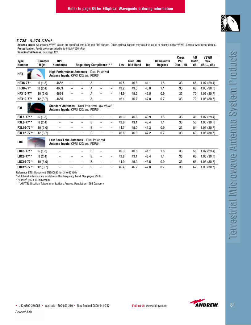
• U.K. 0800-250055 • Australia 1800-803 219 • New Zealand 0800-441-747 Visit us at: www.andrew.com 81
Refer to page 84 for Elliptical Waveguide ordering information
7.725 - 8.275 GHz*Antenna Inputs. All antenna VSWR values are specified with CPR and PDR flanges. Other optional flanges may result in equal or slightly higher VSWR. Contact Andrew for details.Pressurization. Feeds are pressurizable to 8 lb/in2 (56 kPa).ValuLine® Antennas. See page 127.
Cross F/B VSWRType Diameter RPE Gain, dBi Beamwidth Pol. Ratio max.Number ft (m) Number(s) Regulatory Compliance*** Low Mid-Band Top Degrees Disc., dB dB (R.L., dB)
HPXHigh Performance Antennas – Dual PolarizedAntenna Inputs: CPR112G and PDR84
HPX6-77* 6 (1.8) 4652 – – A – – 40.5 40.8 41.1 1.5 33 66 1.07 (29.4)
HPX8-77* 8 (2.4) 4653 – – A – – 43.2 43.5 43.8 1.1 33 68 1.06 (30.7)
HPX10-77* 10 (3.0) 4654 – – A – – 44.9 45.2 45.5 0.9 33 70 1.06 (30.7)
HPX12-77* 12 (3.7) 4655 – – A – – 46.4 46.7 47.0 0.7 33 72 1.06 (30.7)
PXLStandard Antennas – Dual Polarized Low VSWRAntenna Inputs: CPR112G and PDR84
PXL6-77** 6 (1.8) – – – B – – 40.3 40.6 40.9 1.5 33 48 1.07 (29.4)
PXL8-77** 8 (2.4) – – – B – – 42.8 43.1 43.4 1.1 33 50 1.06 (30.7)
PXL10-77** 10 (3.0) – – – B – – 44.7 45.0 45.3 0.9 33 54 1.06 (30.7)
PXL12-77** 12 (3.7) – – – B – – 46.6 46.9 47.2 0.7 33 63 1.06 (30.7)
LBXLow Back Lobe Antennas – Dual PolarizedAntenna Inputs: CPR112G and PDR84
LBX6-77** 6 (1.8) – – B – 40.3 40.8 41.1 1.5 33 56 1.07 (29.4)
LBX8-77** 8 (2.4) – – – B – – 42.8 43.1 43.4 1.1 33 60 1.06 (30.7)
LBX10-77** 10 (3.0) – – – B – – 44.9 45.2 45.5 0.9 33 66 1.06 (30.7)
LBX12-77** 12 (3.7) – – – B – – 46.4 46.7 47.0 0.7 33 67 1.06 (30.7)
Reference ETSI Document EN300833 for 3 to 60 GHz*Multiband antennas are available in this frequency band. See pages 93-94.**8 lb/in2 (56 kPa) maximum***ANATEL Brazilian Telecommunications Agency, Regulation 1286 Category
Revised 5/01
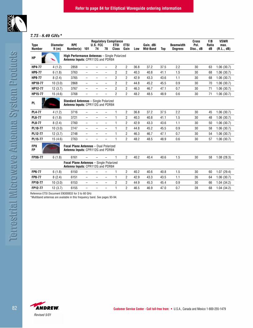
Customer Service Center - Call toll-free from: • U.S.A., Canada and Mexico 1-800-255-147982
Refer to page 84 for Elliptical Waveguide ordering information
7.75 - 8.40 GHz*Regulatory Compliance Cross F/B VSWR
Type Diameter RPE U.S. FCC ETSI ETSI Gain, dBi Beamwidth Pol. Ratio max.Number ft (m) Number(s) 101 74 78 Class Gain Low Mid-Band Top Degrees Disc., dB dB (R.L., dB)
HPHigh Performance Antennas – Single PolarizedAntenna Inputs: CPR112G and PDR84
HP4-77 4 (1.2) 2858 – – – 2 2 36.8 37.2 37.5 2.2 30 63 1.06 (30.7)
HP6-77 6 (1.8) 3763 – – – 2 2 40.3 40.8 41.1 1.5 30 68 1.06 (30.7)
HP8-77 8 (2.4) 3765 – – – 2 2 42.9 43.3 43.6 1.1 30 68 1.06 (30.7)
HP10-77 10 (3.0) 2868 – – – 2 2 44.8 45.2 45.5 0.9 30 70 1.06 (30.7)
HP12-77 12 (3.7) 3767 – – – 2 2 46.3 46.7 47.1 0.7 30 71 1.06 (30.7)
HP15-77 15 (4.6) 3768 – – – 2 2 48.2 48.5 48.9 0.6 30 71 1.06 (30.7)
PLStandard Antennas – Single PolarizedAntenna Inputs: CPR112G and PDR84
PL4-77 4 (1.2) 3716 – – – 1 2 36.8 37.2 37.5 2.2 30 45 1.06 (30.7)
PL6-77 6 (1.8) 3721 – – – 1 2 40.3 40.8 41.1 1.5 30 48 1.06 (30.7)
PL8-77 8 (2.4) 2760 – – – 1 2 42.9 43.3 43.6 1.1 30 50 1.06 (30.7)
PL10-77 10 (3.0) 2747 – – – 1 2 44.8 45.2 45.5 0.9 30 58 1.06 (30.7)
PL12-77 12 (3.7) 2748 – – – 1 2 46.3 46.7 47.1 0.7 30 54 1.06 (30.7)
PL15-77 15 (4.6) 2763 – – – 1 2 48.2 48.5 48.9 0.6 30 57 1.06 (30.7)
FPX Focal Plane Antennas – Dual PolarizedFP Antenna Inputs: CPR112G and PDR84
FPX6-77 6 (1.8) 6161 – – – 1 2 40.2 40.4 40.6 1.5 30 58 1.08 (28.3)
Focal Plane Antennas – Single PolarizedAntenna Inputs: CPR112G and PDR84
FP6-77 6 (1.8) 6150 – – – 1 2 40.2 40.6 40.8 1.5 30 60 1.07 (29.4)
FP8-77 8 (2.4) 6151 – – – 1 2 42.9 43.3 43.5 1.1 26 64 1.06 (30.7)
FP10-77 10 (3.0) 6153 – – – 2 2 44.9 45.3 45.4 0.9 30 66 1.04 (34.2)
FP12-77 12 (3.7) 6155 – – – 1 2 46.5 46.9 47.0 0.7 28 68 1.04 (34.2)
Reference ETSI Document EN300833 for 3 to 60 GHz*Multiband antennas are available in this frequency band. See pages 93-94.
Revised 5/01

• U.K. 0800-250055 • Australia 1800-803 219 • New Zealand 0800-441-747 Visit us at: www.andrew.com 83
8.2 - 8.5 GHzAntenna Inputs. All antenna VSWR values are specified with CPR and PDR flanges. Other optional flanges may result in equal or slightly higher VSWR. Contact Andrew for details.Pressurization. Feeds are pressurizable to 10 lb/in2 (70 kPa) except LBX Series 8 lb/in2 (56 kPa).ValuLine® Antennas. See page 127.
Regulatory Compliance Cross F/B VSWRType Diameter RPE U.S. FCC ETSI ETSI Gain, dBi Beamwidth Pol. Ratio max.Number ft (m) Number(s) 101 74 78 Class Gain Low Mid-Band Top Degrees Disc., dB dB (R.L., dB)
HSXHigh Performance Antennas - Super High Cross Polarization Discrimination – Dual PolarizedAntenna Inputs: CPR112G and PDR84
HSX4-82 4 (1.2) 1799, 1810 – – – 3 2 37.5 37.6 37.7 2.3 40 63 1.08 (28.3)
HSX6-82 6 (1.8) 1222 1224 – – – 3 2 41.3 41.4 41.7 1.4 40 67 1.06 (30.7)
HSX8-82 8 (2.4) 1226 1228 – – – 3 2 43.7 43.8 43.9 1.0 40 78 1.06 (30.7)
HSX10-82 10 (3.0) 1230 1232 – – – 3 2 45.3 45.4 45.5 0.8 40 78 1.06 (30.7)
HSX12-82 12 (3.7) 1236 1234 – – – 3 2 47.1 47.2 47.3 0.7 40 79 1.06 (30.7)
HSX15-82 15 (4.6) 1238 1240 – – – 3 2 48.7 48.8 48.9 0.6 40 76 1.06 (30.7)
HPX High Performance Antennas – Dual PolarizedHP Antenna Inputs: CPR112G and PDR84
HPX6-82 6 (1.8) 2883 – – – 1 2 41.0 41.1 41.2 1.3 30 58 1.08 (28.3)
HPX8-82 8 (2.4) 2863 – – – 2 2 43.5 43.6 43.7 1.0 30 67 1.06 (30.7)
HPX10-82 10 (3.0) 2865 – – – 2 2 45.5 45.6 45.7 0.8 30 70 1.06 (30.7)
HPX12-82 12 (3.7) 2867 – – – 2 2 47.1 47.2 47.3 0.7 30 70 1.06 (30.7)
HPX15-82 15 (4.6) 2869 – – – 2 2 48.7 48.8 48.9 0.6 30 70 1.06 (30.7)
High Performance Antennas – Single PolarizedAntenna Inputs: CPR112G and PDR84
HP6-82 6 (1.8) 2882 – – – 2 2 40.6 40.8 41.0 1.5 30 68 1.06 (30.7)
HP8-82 8 (2.4) 2891 – – – 2 2 43.4 43.5 43.7 1.1 30 68 1.06 (30.7)
HP10-82 10 (3.0) 2893 – – – 2 2 45.3 45.5 45.7 0.9 30 70 1.06 (30.7)
HP12-82 12 (3.7) 2895 – – – 2 2 46.8 47.0 47.1 0.7 30 71 1.06 (30.7)
HP15-82 15 (4.6) 2889 – – – 2 2 48.6 48.8 48.9 0.6 30 71 1.06 (30.7)
PXL Standard Antennas – Dual Polarized Low VSWRPL Antenna Inputs: CPR112G and PDR84
PXL6-82 6 (1.8) 2851 – – – – – 41.0 41.1 41.2 1.3 30 48 1.06 (30.7)
PXL8-82 8 (2.4) 2853 – – – 1 2 43.7 43.8 43.9 1.0 30 55 1.06 (30.7)
PXL10-82 10 (3.0) 2855 – – – 1 2 45.7 45.8 45.9 0.8 30 57 1.06 (30.7)
PXL12-82 12 (3.7) 2857 – – – 1 2 47.3 47.4 47.5 0.7 30 63 1.06 (30.7)
PXL15-82 15 (4.6) 2859 – – – 1 2 48.5 48.6 48.7 0.6 30 65 1.06 (30.7)
Standard Antennas – Single Polarized Low VSWRAntenna Inputs: CPR112G and PDR84
PL6-82 6 (1.8) 2871 – – – 1 2 40.6 40.8 41.0 1.5 30 48 1.06 (30.7)
PL8-82 8 (2.4) 2897 – – – 1 2 43.4 43.5 43.7 1.1 30 50 1.06 (30.7)
PL10-82 10 (3.0) 2899 – – – 1 2 43.3 45.5 45.7 0.9 30 58 1.06 (30.7)
PL12-82 12 (3.7) 2901 – – – 1 2 46.8 47.0 47.1 0.7 30 54 1.06 (30.7)
PL15-82 15 (4.6) 2903 – – – 1 2 48.6 48.8 48.6 0.6 30 57 1.06 (30.7)
LBXLow Back Lobe Antennas – Dual PolarizedAntenna Inputs: CPR112G and PDR84
Regulatory Compliance**
LBX6-82* 6 (1.8) 786-1 – – B – – 40.9 41.1 41.2 1.5 33 58 1.07 (29.4)
LBX8-82* 8 (2.4) 787-2 – – B – – 43.6 43.8 43.9 1.1 33 60 1.06 (30.7)
LBX10-82* 10 (3.0) 788-2 – – B – – 45.6 45.8 45.9 0.9 33 63 1.06 (30.7)
LBX12-82* 12 (3.7) 789-2 – – B – – 46.9 47.1 47.2 0.7 33 65 1.06 (30.7)
Reference ETSI Document EN300833 for 3 to 60 GHz*8 lb/in2 (56 kPa) maximum**ANATEL Brazilian Telecommunications Agency, Regulation 1286 Category
Refer to page 84 for Elliptical Waveguide ordering information
Revised 5/01

Customer Service Center - Call toll-free from: • U.S.A., Canada and Mexico 1-800-255-147984
Ordering Information for Waveguide AssembliesFrequency* Waveguide Flange Connector† Flex-Twist
GHz Type Type†† Tunable Fixed-Tuned Pressure Window 2 ft (0.6 m)
Premium Waveguide Assemblies VSWR 1.06 (30.7)**
7.125–7.750 EWP77-71 UG-51/U††† 177DCT 177SC 55000A-112 F112PA0240BACPR112G 177DET 177SE 55001-112 F112PC0240CAPBR84 177DCMT 177SCM 243498-84 F112MK0600KAPDR84 177DEMT 177SEM 223306-84 F112MH0600HAPDR70 277DEMT – 223306-70 F137MH0600HC
7.725–8.500 EWP77-77 UG-51/U††† 177DCT 177SC 55000A-112 F112PA0240BBCPR112G 177DET 177SE 55001-112 F112PC0240CBPBR84 177DCMT 177SCM 243498-84 F112MK0600KBPDR84 177DEMT 177SEM 223306-84 F112MH0600HBPDR70 277DEMT – 223306-70 F137MH0600HF‡
7.125–8.500 EWP77-71W UG-51/U††† 177DCT 177SC 55000A-112 F112PA0240BCCPR112G 177DET 177SE 55001-112 F112PC0240CCPBR84 177DCMT 177SCM 243498-84 F112MK0600KCPDR84 177DEMT 177SEM 223306-84 F112MH0600HC
*** PDR70 277DEMT – 223306-70 F137MH0600HE
Standard Waveguide Assemblies Non-Tunable VSWR 1.15 (23.1)**
7.125–8.500 EW77 UG-51/U††† 177DC 177SC 55000A-112 F112PA0240BCPBR84 177DCM 177SCM 243498-84 F112MK0600KCCPR112G 177DE 177SE 55001-112 F112PC0240CCPDR84 177DEM 177SEM 223306-84 F112MH0600HC
* Contact Andrew for information on other frequency bands. ** VSWR max., (R.L., dB). Up to 300 ft (90 m). The indicated maximum VSWR characteristics are guaranteed for factory assemblies and are typical for field assemblies. *** 7.425 - 7.925 GHz ‡ 7.725 - 8.3 GHz ONLY
† “Tunable” connectors ordered with factory assemblies are factory tuned. †† For detailed information on mating flanges, refer to pages 214-218. ††† Modified cover flange with gasket groove. Mates with UG choke or cover flanges.
Description Type No.
Hangers and Adapters
Hanger Kit of 10, Recommended maximum spacingfor outdoor installation is 3 ft (0.91 m)* 42396A-11NEW! Snap-In Hanger Kit of 10. Recommended spacing for outdoor installation is 3 ft (0.91 m) EWSH-77Hardware Kit of 10, 3/8" bolts, lock washers, nuts
3/4" (19 mm) long 31769-51" (25 mm) long 31769-1
Angle Adapter Kit of 10. Stainless steel 31768AAngle Adapter Kit of 10. Galvanized
3/8" Hardware 242774Metric Hardware 242774-M
Round Member Adapter Kit of 10. Stainless steelMember Diameter, in (mm)
1-2 (25-50) 31670-12-3 (50-75) 31670-23-4 (75-100) 31670-34-5 (100-125) 31670-45-6 (125-150) 31670-5
45° Adapter Kit of 10. Galvanized steel 42334Threaded Rod Support, 3/8” rod, nuts, washers, ceiling bracket
12 in (305 mm) long, kit of 1 3177112 in (305 mm) long, kit of 5 31771-424 in (610 mm) long, kit of 1 31771-924 in (610 mm) long, kit of 5 31771-6
Tower Standoff Kit of 10. 1 in (25 mm) standoffMember Diameter, in (mm)
0.75-1.5 (20-40) 30848-51.5-3.0 (40-75) 30848-43-4 (75-100) 30848-14-5 (100-125) 30848-25-6 (125-150) 30848-3
* Standard conditions: 125 mph (200 km/h) survival wind velocity, 0.5 in (13 mm) radial ice. For other conditions see page 196.
Description Type No.
Tower Standoff Kit of 10. 2.5 in (60 mm) standoffMember Diameter, in (mm)
3-4 (75-100) 41108A-14-5 (100-125) 41108A-25-6 (125-150) 41108A-3
Other Accessories
Flaring Tool Kit for connector attachment 202421Splice 177DZGrounding Kit with factory attached, one-hole lug 204989-3Grounding Kit with factory attached, two-hole lug 241088-3Grounding Kit with field attachable crimp-on, one-hole lug 204989-23Grounding Kit with field attachable crimp-on, two-hole lug 241088-8Grounding Kit with field attachable screw-on lug 204989-33Crimping Tool to field attach lug to Grounding Kit 207270Hoisting Grip 19256BBending Tool Kit. One each E and H Plane tool EWBTK-2Connector Reattachment Kit 33544-34Wall-Roof Feed Thru 245314-77Waveguide Boot for Plates (below),
4 in (102 mm) dia. WGB4-775 in (127 mm) dia WGB5-77
Feed-Thru Plate for Boots (above)
Openings For 4 in Boots For 5 in Boots
1 204673-1 48940-11 204673-2 –2 – 48940-23 – 48940-34 204673-4 48940-46 – 48940-68 204673-8 –
Accessories – Photos and detailed descriptions on pages 194-200
Revised 5/01
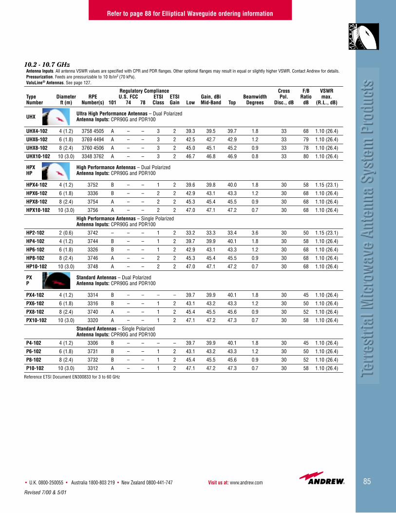
• U.K. 0800-250055 • Australia 1800-803 219 • New Zealand 0800-441-747 Visit us at: www.andrew.com 85
10.2 - 10.7 GHzAntenna Inputs. All antenna VSWR values are specified with CPR and PDR flanges. Other optional flanges may result in equal or slightly higher VSWR. Contact Andrew for details.Pressurization. Feeds are pressurizable to 10 lb/in2 (70 kPa).ValuLine® Antennas. See page 127.
Regulatory Compliance Cross F/B VSWRType Diameter RPE U.S. FCC ETSI ETSI Gain, dBi Beamwidth Pol. Ratio max.Number ft (m) Number(s) 101 74 78 Class Gain Low Mid-Band Top Degrees Disc., dB dB (R.L., dB)
UHXUltra High Performance Antennas – Dual PolarizedAntenna Inputs: CPR90G and PDR100
UHX4-102 4 (1.2) 3758 4505 A – – 3 2 39.3 39.5 39.7 1.8 33 68 1.10 (26.4)
UHX6-102 6 (1.8) 3769 4494 A – – 3 2 42.5 42.7 42.9 1.2 33 79 1.10 (26.4)
UHX8-102 8 (2.4) 3760 4506 A – – 3 2 45.0 45.1 45.2 0.9 33 78 1.10 (26.4)
UHX10-102 10 (3.0) 3348 3762 A – – 3 2 46.7 46.8 46.9 0.8 33 80 1.10 (26.4)
HPX High Performance Antennas – Dual PolarizedHP Antenna Inputs: CPR90G and PDR100
HPX4-102 4 (1.2) 3752 B – – 1 2 39.6 39.8 40.0 1.8 30 58 1.15 (23.1)
HPX6-102 6 (1.8) 3336 B – – 2 2 42.9 43.1 43.3 1.2 30 68 1.10 (26.4)
HPX8-102 8 (2.4) 3754 A – – 2 2 45.3 45.4 45.5 0.9 30 68 1.10 (26.4)
HPX10-102 10 (3.0) 3756 A – – 2 2 47.0 47.1 47.2 0.7 30 68 1.10 (26.4)
High Performance Antennas – Single PolarizedAntenna Inputs: CPR90G and PDR100
HP2-102 2 (0.6) 3742 – – – 1 2 33.2 33.3 33.4 3.6 30 50 1.15 (23.1)
HP4-102 4 (1.2) 3744 B – – 1 2 39.7 39.9 40.1 1.8 30 58 1.10 (26.4)
HP6-102 6 (1.8) 3326 B – – 1 2 42.9 43.1 43.3 1.2 30 68 1.10 (26.4)
HP8-102 8 (2.4) 3746 A – – 2 2 45.3 45.4 45.5 0.9 30 68 1.10 (26.4)
HP10-102 10 (3.0) 3748 A – – 2 2 47.0 47.1 47.2 0.7 30 68 1.10 (26.4)
PX Standard Antennas – Dual PolarizedP Antenna Inputs: CPR90G and PDR100
PX4-102 4 (1.2) 3314 B – – – – 39.7 39.9 40.1 1.8 30 45 1.10 (26.4)
PX6-102 6 (1.8) 3316 B – – 1 2 43.1 43.2 43.3 1.2 30 50 1.10 (26.4)
PX8-102 8 (2.4) 3740 A – – 1 2 45.4 45.5 45.6 0.9 30 52 1.10 (26.4)
PX10-102 10 (3.0) 3320 A – – 1 2 47.1 47.2 47.3 0.7 30 58 1.10 (26.4)
Standard Antennas – Single PolarizedAntenna Inputs: CPR90G and PDR100
P4-102 4 (1.2) 3306 B – – – – 39.7 39.9 40.1 1.8 30 45 1.10 (26.4)
P6-102 6 (1.8) 3731 B – – 1 2 43.1 43.2 43.3 1.2 30 50 1.10 (26.4)
P8-102 8 (2.4) 3732 B – – 1 2 45.4 45.5 45.6 0.9 30 52 1.10 (26.4)
P10-102 10 (3.0) 3312 A – – 1 2 47.1 47.2 47.3 0.7 30 58 1.10 (26.4)
Reference ETSI Document EN300833 for 3 to 60 GHz
Refer to page 88 for Elliptical Waveguide ordering information
Revised 7/00 & 5/01

Customer Service Center - Call toll-free from: • U.S.A., Canada and Mexico 1-800-255-147986
10.5 - 10.7 GHzAntenna Inputs. All antenna VSWR values are specified with CPR and PDR flanges. Other optional flanges may result in equal or slightly higher VSWR. Contact Andrew for details.Pressurization. Feeds are pressurizable to 10 lb/in2 (70 kPa).ValuLine® Antennas. See page 127.
Regulatory Compliance Cross F/B VSWRType Diameter RPE U.S. FCC ETSI ETSI Gain, dBi Beamwidth Pol. Ratio max.Number ft (m) Number(s) 101 74 78 Class Gain Low Mid-Band Top Degrees Disc., dB dB (R.L., dB)
UHXUltra High Performance Antennas – Dual PolarizedAntenna Inputs: CPR90G and PDR100
UHX4-105 4 (1.2) 2013 2012 A – – 3 2 39.8 39.9 40.0 1.7 33 70 1.08 (28.3)UHX6-105 6 (1.8) 2037 2038 A – – 3 2 43.4 43.5 43.6 1.2 33 81 1.06 (30.7)UHX8-105 8 (2.4) 2024 2025 A – – 3 2 45.8 45.9 46.0 1.0 33 80 1.06 (30.7)UHX10-105 10 (3.0) 2033 2032 A – – 3 2 47.8 47.9 48.0 0.8 33 83 1.06 (30.7)UHX12-105 12 (3.7) 2034 2035 A – – 3 2 49.2 49.3 49.4 0.65 33 80 1.06 (30.7)
HSXHigh Performance Antennas – Super High Cross Polarization Discrimination – Dual PolarizedAntenna Inputs: CPR90G and PDR100
HSX4-105 4 (1.2) 1972 1974 A – – 2 2 39.6 39.7 39.8 1.7 40 64 1.10 (26.4)HSX6-105 6 (1.8) 1976 1980 A – – 3 2 43.2 43.4 43.5 1.1 40 72 1.08 (28.3)HSX8-105 8 (2.4) 2017 2019 A – – 3 2 45.8 45.9 46.0 0.8 40 75 1.06 (30.7)HSX10-105 10 (3.0) 2026 2028 A – – 3 2 47.6 47.7 47.8 0.7 40 75 1.06 (30.7)HSX12-105 12 (3.7) 2253 2255 A – – 3 2 49.5 49.3 49.2 0.6 40 80 1.06 (30.7)
HPX High Performance Antennas – Dual PolarizedHP Antenna Inputs: CPR90G and PDR100
HPX4-105 4 (1.2) 2462 B – – 2 2 39.8 39.9 40.0 1.8 30 60 1.10 (26.4)HPX6-105 6 (1.8) 3269 A – – 2 2 43.4 43.5 43.6 1.2 30 64 1.08 (28.3)HPX8-105 8 (2.4) 3274 A – – 2 2 45.8 45.9 46.0 0.9 30 68 1.06 (30.7)HPX10-105 10 (3.0) 3280 A – – 2 2 47.7 47.8 47.9 0.8 30 70 1.06 (30.7)HPX12-105 12 (3.7) 3282 A – – 2 2 49.2 49.3 49.4 0.7 30 71 1.06 (30.7)
High Performance Antennas – Single PolarizedAntenna Inputs: CPR90G and PDR100
HP4-105 4 (1.2) 3472 B – – 2 2 39.8 39.9 40.0 1.8 30 60 1.08 (28.3)HP6-105 6 (1.8) 3258 B – – 2 2 43.4 43.5 43.6 1.2 30 66 1.06 (30.7)HP8-105 8 (2.4) 3259 A – – 2 2 45.8 45.9 46.0 0.9 30 68 1.06 (30.7)HP10-105 10 (3.0) 3260 A – – 2 2 47.7 47.8 47.9 0.8 30 70 1.06 (30.7)HP12-105 12 (3.7) 3261 A – – 1 2 49.2 49.3 49.4 0.7 30 71 1.06 (30.7)
PX Standard Antennas – Dual PolarizedP Antenna Inputs: CPR90G and PDR100PX6-105 6 (1.8) 3290 B – – 1 2 43.4 43.5 43.6 1.2 30 49 1.15 (23.1)PX8-105 8 (2.4) 3291 B – – 1 2 45.8 45.9 46.0 0.9 30 50 1.10 (26.4)PX10-105 10 (3.0) 3292 B – – 1 2 47.7 47.8 47.9 0.8 30 52 1.10 (26.4)PX12-105 12 (3.7) 3293 B – – 1 2 49.2 49.3 49.4 0.7 30 55 1.10 (26.4)
Standard Antennas – Single PolarizedAntenna Inputs: CPR90G and PDR100
P4-105 4 (1.2) 3002 B – – – – 39.8 39.9 40.0 1.8 30 45 1.15 (23.1)P6-105 6 (1.8) 3146 B – – 1 2 43.4 43.5 43.6 1.2 30 51 1.10 (26.4)P8-105 8 (2.4) 3004 B – – 1 2 45.8 45.9 46.0 0.9 30 53 1.10 (26.4)P10-105 10 (3.0) 3006 A – – 1 2 47.8 47.9 48.0 0.8 30 53 1.10 (26.4)P12-105 12 (3.7) 3218 B – – 1 2 49.2 49.3 49.4 0.7 30 55 1.10 (26.4)
PARStandard Antennas – Single Polarized Low VSWRAntenna Inputs: CPR90G and PDR100
PAR6-105* 6 (1.8) 1646 A – – 1 2 43.0 43.1 43.2 1.2 30 60 1.06 (30.7)PAR8-105* 8 (2.4) 1647 A – – 1 2 45.6 45.7 45.8 0.9 30 63 1.06 (30.7)
Reference ETSI Document EN300833 for 3 to 60 GHz* Uses focal plane reflector and feed system.
Refer to page 88 for Elliptical Waveguide ordering information
Revised 7/00 & 5/01

87
10.5 - 11.7 GHz*Antenna Inputs. All antenna VSWR values are specified with CPR and PDR flanges. Other optional flanges may result in equal or slightly higher VSWR. Contact Andrew for details.Pressurization. Feeds are pressurizable to 10 lb/in2 (70 kPa). ValuLine® Antennas. See page 127.
Regulatory Compliance Cross F/B VSWRType Diameter RPE U.S. FCC ETSI ETSI Gain, dBi Beamwidth Pol. Ratio max.Number ft (m) Number(s) 101 74 78 Class Gain Low Mid-Band Top Degrees Disc., dB dB (R.L., dB)
UHXUltra High Performance Antennas – Dual PolarizedAntenna Inputs: CPR90G and PDR100
UHX4-107 4 (1.2) 2098 2097 A – – 3 2 40.0 40.4 40.8 1.6 33 70 1.08 (28.3)UHX6-107 6 (1.8) 2141 2142 A – – 3 2 43.6 44.0 44.4 1.1 33 80 1.06 (30.7)UHX8-107 8 (2.4) 2124 2125 A – – 3 2 46.0 46.5 46.8 0.8 33 80 1.06 (30.7)UHX10-107 10 (3.0) 2127 2126 A – – 3 2 47.6 48.0 48.3 0.7 33 82 1.06 (30.7)UHX12-107 12 (3.7) 2128 2129 A – – 3 2 49.4 49.8 50.2 0.5 33 80 1.06 (30.7)
HSXHigh Performance Antennas - Super High Cross Polarization Discrimination – Dual PolarizedAntenna Inputs: CPR90G and PDR100
HSX4-107 4 (1.2) 2314 2312 A – – 2 2 39.8 40.2 40.6 1.6 40 64 1.10 (26.4)HSX6-107 6 (1.8) 2316 2318 A – – 3 2 43.5 43.9 44.3 1.1 40 72 1.08 (28.3)HSX8-107 8 (2.4) 2320 2322 A – – 2 2 46.0 46.5 46.8 0.8 40 75 1.06 (30.7)HSX10-107 10 (3.0) 2340 2338 A – – 2 2 47.8 48.2 48.6 0.7 40 75 1.06 (30.7)HSX12-107 12 (3.7) 2362 2364 A – – 3 2 49.2 49.6 50.3 0.5 40 80 1.06 (30.7)
HPX High Performance Antennas – Dual PolarizedHP Antenna Inputs: CPR90G and PDR100
HPX4-107 4 (1.2) 2460 B – – 2 2 40.0 40.3 40.6 1.6 30 62 1.10 (26.4)HPX6-107 6 (1.8) 3224 A – – 2 2 43.6 44.0 44.4 1.0 30 70 1.08 (28.3)HPX8-107 8 (2.4) 3175 A – – 2 2 46.0 46.4 46.8 0.8 30 70 1.06 (30.7)HPX10-107 10 (3.0) 3173 A – – 2 2 47.9 48.3 48.6 0.7 30 70 1.06 (30.7)HPX12-107 12 (3.7) 3190 A – – 2 2 49.4 49.8 50.2 0.5 30 72 1.06 (30.7)
High Performance Antennas – Single PolarizedAntenna Inputs: CPR90G and PDR100
HP4-107 4 (1.2) 3429 A – – 2 2 40.0 40.4 40.8 1.6 30 61 1.08 (28.3)HP6-107 6 (1.8) 3222 A – – 3 2 43.6 44.0 44.4 1.0 30 70 1.06 (30.7)HP8-107 8 (2.4) 3174 A – – 3 2 46.0 46.4 46.8 0.8 30 71 1.06 (30.7)HP10-107 10 (3.0) 3250 A – – 2 2 47.9 48.3 48.6 0.7 30 70 1.06 (30.7)HP12-107 12 (3.7) 3188 A – – 2 2 49.4 49.8 50.2 0.5 30 70 1.06 (30.7)
HDXHigh Performance, Dual Beam Antennas – Dual Polarized Angle DiversityAntenna Input: CPR90G
HDX8-107 8 (2.4) 3791 3793 A – – 2 2 47.6 47.9 48.1 0.8 26 78 1.10 (26.4)3787 3789
HDX10-107 10 (3.0) 4352 4353 A – – 2 2 47.6 47.9 48.1 0.8 22 78 1.10 (26.4)4354 4355
PARStandard Antennas – Single PolarizedAntenna Inputs: CPR90G and PDR100
PAR6-107** 6 (1.8) 3743 A – – 1 2 43.2 43.6 44.0 1.1 30 60 1.06 (30.7)PAR8-107** 8 (2.4) 3745 A – – 1 2 45.8 46.2 46.6 0.8 30 63 1.06 (30.7)
PXL Standard Antennas – Dual Polarized Low VSWRPL Antenna Inputs: CPR90G and PDR100
PXL6-107 6 (1.8) 3183 B – – – – 43.6 44.0 44.4 1.0 30 49 1.08 (28.3)PXL8-107 8 (2.4) 3185 B – – – – 46.0 46.4 46.8 0.8 30 50 1.06 (30.7)PXL10-107 10 (3.0) 3187 B – – – – 47.9 48.3 48.6 0.7 30 52 1.06 (30.7)PXL12-107 12 (3.7) 3199 B – – – – 49.4 49.8 50.2 0.5 30 53 1.06 (30.7)
Standard Antennas – Single Polarized Low VSWRAntenna Inputs: CPR90G and PDR100
PL4-107 4 (1.2) 3214 B – – – – 40.1 40.5 40.9 1.6 30 46 1.08 (28.3)PL6-107 6 (1.8) 3101 B – – 1 2 43.6 44.0 44.4 1.0 30 51 1.06 (30.7)PL8-107 8 (2.4) 3249 B – – 1 2 46.0 46.4 46.8 0.8 30 53 1.06 (30.7)PL10-107 10 (3.0) 3200 B – – – – 47.8 48.2 48.5 0.7 30 54 1.06 (30.7)PL12-107 12 (3.7) 3116 B – – 1 2 49.4 49.8 50.2 0.5 30 60 1.06 (30.7)
Reference ETSI Document EN300833 for 3 to 60 GHz* Multiband antennas are available for this frequency band. See pages 93-94. ** Uses focal plane reflector and feed system
• U.K. 0800-250055 • Australia 1800-803 219 • New Zealand 0800-441-747 Visit us at: www.andrew.com
Refer to page 88 for Elliptical Waveguide ordering information
Revised 5/01
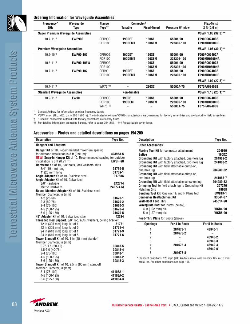
Customer Service Center - Call toll-free from: • U.S.A., Canada and Mexico 1-800-255-147988
Ordering Information for Waveguide AssembliesFrequency* Waveguide Flange Connector† Flex-Twist
GHz Type Type†† Tunable Fixed-Tuned Pressure Window 2 ft (0.6 m)
Super Premium Waveguide Assemblies VSWR 1.05 (32.3)**
10.7-11.7 EWP90S CPR90G 190DET 190SE 55001-90 F090PC0240CBPDR100 190DEMT 190SEM 223306-100 F090MH0600HB
Premium Waveguide Assemblies VSWR 1.06 (30.7)**
10.2-10.7 EWP90-105 CPR90G 190DET 190SE 55001-90 F090PC0240CAPDR100 190DEMT 190SEM 223306-100 F090MH0600HA
10.5-11.7 EWP90-105W CPR90G – 190SE 55001-90 F090PC0240CBPDR100 – 190SEM 223306-100 F090MH0600HB
10.7-11.7 EWP90-107 CPR90 190DET 190SE 55001-90 F090PC0240CBPDR100 190DEMT 190SEM 223306-100 F090MH0600HB
VSWR 1.09 (27.3)**
10.7-11.7 WR75††† – 290SC 55000A-75 F075PA0240BB
Standard Waveguide Assemblies Non-Tunable VSWR 1.15 (23.1)**
10.2-11.7 EW90 CPR90G 190DE 190SE 55001-90 F090PC0240CSPDR100 190DEM 190SEM 223306-100 F090MH0600HSWR75††† – – 55000A-75 F075PA0240BS
* Contact Andrew for information on other frequency bands. ** VSWR max., (R.L., dB). Up to 300 ft (90 m). The indicated maximum VSWR characteristics are guaranteed for factory assemblies and are typical for field assemblies.† “Tunable” connectors ordered with factory assemblies are factory tuned. †† For detailed information on mating flanges, refer to pages 214-218. ††† Pressurizable cover flange.
Description Type No.
Hangers and Adapters
Hanger Kit of 10, Recommended maximum spacingfor outdoor installation is 3 ft (0.91 m)* 42396A-5NEW! Snap-In Hanger Kit of 10. Recommended spacing for outdoor installation is 3 ft (0.91 m) EWSH-90Hardware Kit of 10, 3/8" bolts, lock washers, nuts
3/4" (19 mm) long 31769-51" (25 mm) long 31769-1
Angle Adapter Kit of 10. Stainless steel 31768AAngle Adapter Kit of 10. Galvanized
3/8" Hardware 242774Metric Hardware 242774-M
Round Member Adapter Kit of 10. Stainless steelMember Diameter, in (mm)
1-2 (25-50) 31670-12-3 (50-75) 31670-23-4 (75-100) 31670-34-5 (100-125) 31670-45-6 (125-150) 31670-5
45° Adapter Kit of 10. Galvanized steel 42334Threaded Rod Support, 3/8” rod, nuts, washers, ceiling bracket
12 in (305 mm) long, kit of 1 3177112 in (305 mm) long, kit of 5 31771-424 in (610 mm) long, kit of 1 31771-924 in (610 mm) long, kit of 5 31771-6
Tower Standoff Kit of 10. 1 in (25 mm) standoffMember Diameter, in (mm)
0.75-1.5 (20-40) 30848-51.5-3.0 (40-75) 30848-43-4 (75-100) 30848-14-5 (100-125) 30848-25-6 (125-150) 30848-3
Tower Standoff Kit of 10. 2.5 in (60 mm) standoffMember Diameter, in (mm)
3-4 (75-100) 41108A-14-5 (100-125) 41108A-25-6 (125-150) 41108A-3
Description Type No.
Other Accessories
Flaring Tool Kit for connector attachment 204919Splice 190DZGrounding Kit with factory attached, one-hole lug 204989-2Grounding Kit with factory attached, two-hole lug 241088-2Grounding Kit with field attachable crimp-on, one-hole lug 204989-22Grounding Kit with field attachable crimp-on, two-hole lug 241088-7Grounding Kit with field attachable screw-on lug 204989-32Crimping Tool to field attach lug to Grounding Kit 207270Hoisting Grip 29958Bending Tool Kit. One each E and H Plane tool EWBTK-1Connector Reattachment Kit 33544-37Wall-Roof Feed Thru 245314-90Waveguide Boot for Plates (below),
4 in (102 mm) dia. WGB4-905 in (127 mm) dia WGB5-90
Feed-Thru Plate for Boots (above)
Openings For 4 in Boots For 5 in Boots
1 204673-1 48940-11 204673-2 –2 – 48940-23 – 48940-34 204673-4 48940-46 – 48940-68 204673-8 –
* Standard conditions: 125 mph (200 km/h) survival wind velocity, 0.5 in (13 mm) radial ice. For other conditions see page 196.
Accessories – Photos and detailed descriptions on pages 194-200
Revised 5/01

• U.K. 0800-250055 • Australia 1800-803 219 • New Zealand 0800-441-747 Visit us at: www.andrew.com 89
12.2 - 13.25 GHzAntenna Inputs. All antenna VSWR values are specified with PDR flange. Other optional flanges may result in equal or slightly higher VSWR. Contact Andrew for details.Pressurization. Feeds are pressurizable to 10 lb/in2 (70 kPa). ValuLine® Antennas. See page 127.
Regulatory Compliance Cross F/B VSWRType Diameter RPE U.S. FCC ETSI ETSI Gain, dBi Beamwidth Pol. Ratio max.Number ft (m) Number(s) 101 74 78 Class Gain Low Mid-Band Top Degrees Disc., dB dB (R.L., dB)
HPHigh Performance Antennas – Single PolarizedAntenna Inputs: WR75 cover/gasket and PDR120
HP6-122 6 (1.8) 3284 A A A 2 2 44.7 45.1 45.4 0.9 30 70 1.08 (28.3)HP8-122 8 (2.4) 3228 A A A 2 2 47.2 47.6 47.9 0.7 30 70 1.08 (28.3)HP10-122 10 (3.0) 3270 A A A 2 2 48.4 48.8 49.1 0.6 28 71 1.08 (28.3)HP12-122 12 (3.7) 3272 A A A 2 2 50.6 50.9 51.2 0.5 30 71 1.08 (28.3)
P Standard Antennas – Single PolarizedAntenna Inputs: WR75 cover/gasket and PDR120
P2-122 2 (0.6) 3216 – – – – – 35.1 35.5 35.8 2.8 25 42 1.10 (26.4)P4-122 4 (1.2) 3204 B B B 1 2 41.2 41.5 41.9 1.4 30 49 1.10 (26.4)P6-122 6 (1.8) 1277 A A A 1 2 44.7 45.1 45.4 0.9 30 55 1.08 (28.3)P8-122 8 (2.4) 1286 A A A 1 2 47.2 47.6 47.9 0.7 30 59 1.08 (28.3)P10-122 10 (3.0) 1288 A A A 1 2 48.4 48.8 49.1 0.6 26 60 1.08 (28.3)P12-122 12 (3.7) 4271 A A A 1 2 50.6 50.9 51.2 0.5 30 58 1.08 (28.3)
12.7 - 13.25 GHz*Antenna Inputs. All antenna VSWR values are specified with PDR flange. Other optional flanges may result in equal or slightly higher VSWR. Contact Andrew for details.Pressurization. Feeds are pressurizable to 10 lb/in2 (70 kPa).ValuLine® Antennas. See page 127.
Regulatory Compliance Cross F/B VSWRType Diameter RPE U.S. FCC ETSI ETSI Gain, dBi Beamwidth Pol. Ratio max.Number ft (m) Number(s) 101 74 78 Class Gain Low Mid-Band Top Degrees Disc., dB dB (R.L., dB)
UHXUltra High Performance Antennas – Dual PolarizedAntenna Inputs: WR75 cover/gasket and PDR120
UHX8-127 8 (2.4) 1255 1256 A A A 3 2 47.5 47.6 47.8 0.7 32 80 1.10 (26.4)UHX10-127 10 (3.0) 1258 1259 A A A 3 2 48.7 48.8 49.0 0.6 30 82 1.10 (26.4)
HPXHigh Performance Antennas – Dual PolarizedAntenna Inputs: WR75 cover/gasket and PDR120
HPX6-127 6 (1.8) 3296 B B B 2 2 45.0 45.1 45.3 0.9 30 68 1.10 (26.4)HPX8-127 8 (2.4) 3278 A A A 2 2 47.5 47.6 47.8 0.7 30 70 1.10 (26.4)HPX10-127 10 (3.0) 3279 A A A 2 2 48.7 48.8 49.0 0.6 25 71 1.10 (26.4)HPX12-127 12 (3.7) 3281 A A A 2 2 50.8 50.9 51.1 0.5 25 72 1.10 (26.4)
Reference ETSI Document EN300833 for 3 to 60 GHz*Multiband antennas are available in this frequency band. See page 94.
Refer to page 185 for Elliptical Waveguide ordering information
12.2 - 12.7 GHzAntenna Inputs. All antenna VSWR values are specified with PDR flange. Other optional flanges may result in equal or slightly higher VSWR. Contact Andrew for details.Pressurization. Feeds are pressurizable to 10 lb/in2 (70 kPa). ValuLine® Antennas. See page 127.
Regulatory Compliance Cross F/B VSWRType Diameter RPE U.S. FCC ETSI ETSI Gain, dBi Beamwidth Pol. Ratio max.Number ft (m) Number(s) 101 74 78 Class Gain Low Mid-Band Top Degrees Disc., dB dB (R.L., dB)
HPXHigh Performance Antennas – Dual PolarizedAntenna Inputs: WR75 cover/gasket and PDR120
HPX6-122 6 (1.8) 3285 A – – 2 2 44.6 44.8 45.0 0.9 30 68 1.10 (26.4)HPX8-122 8 (2.4) 3232 A – – 2 2 47.1 47.3 47.5 0.7 30 70 1.10 (26.4)HPX10-122 10 (3.0) 3233 A – – 2 2 48.4 48.5 48.7 0.6 25 71 1.10 (26.4)HPX12-122 12 (3.7) 3234 A – – 1 2 50.5 50.6 50.8 0.5 25 71 1.10 (26.4)
PXStandard Antennas – Dual PolarizedAntenna Inputs: WR75 cover/gasket and PDR120
PX4-122 4 (1.2) 3211 B – – 1 2 40.5 40.7 40.9 1.4 25 52 1.10 (26.4)PX6-122 6 (1.8) 3213 A – – – – 44.6 44.8 45.0 0.9 25 51 1.10 (26.4)PX8-122 8 (2.4) 3215 A – – – – 47.1 47.3 47.5 0.7 30 54 1.10 (26.4)PX10-122 10 (3.0) 3217 A – – – – 48.4 48.5 48.7 0.6 30 57 1.10 (26.4)PX12-122 12 (3.7) 3219 A – – – – 50.5 50.6 50.8 0.5 25 58 1.10 (26.4)
Continued on next page
Revised 5/01

Customer Service Center - Call toll-free from: • U.S.A., Canada and Mexico 1-800-255-147990
12.75 - 13.25 GHz*Antenna Inputs. All antenna VSWR values are specified with PDR flange. Other optional flanges may result in equal or slightly higher VSWR. Contact Andrew for details.Pressurization. Feeds are pressurizable to 10 lb/in2 (70 kPa).ValuLine® Antennas. See page 127.
Regulatory Compliance Cross F/B VSWRType Diameter RPE U.S. FCC ETSI ETSI Gain, dBi Beamwidth Pol. Ratio max.Number ft (m) Number(s) 101 74 78 Class Gain Low Mid-Band Top Degrees Disc., dB dB (R.L., dB)
HSXHigh Performance Antennas- Super High Cross Polarization Discrimination – Dual PolarizedAntenna Input: PDR120
HSX4-130 4 (1.2) 2490 2492 B B B 3 2 41.4 41.6 41.8 1.6 40 68 1.10 (26.4)
HSX6-130 6 (1.8) 2099 2100 A A A 3 2 44.9 45.1 45.3 0.9 40 75 1.10 (26.4)
HSX8-130 8 (2.4) 2513 2515 A A A 3 2 47.4 47.6 47.8 0.7 40 76 1.10 (26.4)
HSX10-130 10 (3.0) 2566 2568 A A A 3 2 48.7 48.8 49.0 0.6 40 76 1.10 (26.4)
HPX High Performance Antennas – Dual PolarizedHP Antenna Inputs: WR75 cover/gasket and PDR120
HPX4-130 4 (1.2) 1254 B B B 3 2 40.9 41.0 41.1 1.3 28 66 1.10 (26.4)
HPX6-130 6 (1.8) 3288 A A A 2 2 45.0 45.1 45.2 0.9 28 68 1.10 (26.4)
HPX8-130 8 (2.4) 1033 A A A 3 2 47.6 47.7 47.8 0.7 32 74 1.10 (26.4)
High Performance Antennas – Single PolarizedAntenna Inputs: WR75 cover/gasket and PDR120
HP4-130 4 (1.2) 1252 A A A 3 2 40.9 41.0 41.1 1.3 28 68 1.10 (26.4)
HP6-130 6 (1.8) 3286 A A A 2 2 45.1 45.2 45.3 0.9 28 70 1.08 (28.3)
HP8-130 8 (2.4) 3289 A A A 2 2 47.6 47.7 47.8 0.7 28 71 1.08 (28.3)
14.25 - 14.5 GHzAntenna Inputs. All antenna VSWR values are specified with PDR flange. Other optional flanges may result in equal or slightly higher VSWR. Contact Andrew for details.Pressurization. Feeds are pressurizable to 10 lb/in2 (70 kPa).ValuLine® Antennas. See page 127.
Regulatory Compliance Cross F/B VSWRType Diameter RPE U.S. FCC ETSI ETSI Gain, dBi Beamwidth Pol. Ratio max.Number ft (m) Number(s) 101 74 78 Class Gain Low Mid-Band Top Degrees Disc., dB dB (R.L., dB)
HSXHigh Performance Antennas – Dual PolarizedAntenna Input: PDR140
HSX4-142 4 (1.2) 1010 1012 – – – 2 2 42.5 42.6 42.7 1.2 40 68 1.10 (26.4)
HSX6-142 6 (1.8) 1014 1016 – – – 2 2 45.9 46.0 46.1 0.8 40 75 1.10 (26.4)
HSX8-142 8 (2.4) 1018 1020 – – – 2 2 48.4 48.5 48.6 0.6 40 76 1.10 (26.4)
HSX10-142 10 (3.0) 1202 1204 – – – 2 2 50.1 50.2 50.3 0.5 40 76 1.10 (26.4)
Reference ETSI Document EN300833 for 3 to 60 GHz* Multiband antennas are available in this frequency band. See page 94.
Refer to pages 185 and 187 for Elliptical Waveguide ordering information
12.7 - 13.25 GHz*Antenna Inputs. All antenna VSWR values are specified with PDR flange. Other optional flanges may result in equal or slightly higher VSWR. Contact Andrew for details.Pressurization. Feeds are pressurizable to 10 lb/in2 (70 kPa). ValuLine® Antennas. See page 127.
Regulatory Compliance Cross F/B VSWRType Diameter RPE U.S. FCC ETSI ETSI Gain, dBi Beamwidth Pol. Ratio max.Number ft (m) Number(s) 101 74 78 Class Gain Low Mid-Band Top Degrees Disc., dB dB (R.L., dB)
PXStandard Antennas – Dual PolarizedAntenna Inputs: WR75 cover/gasket and PDR120
PX4-127 4 (1.2) 3220 B B B 1 2 40.9 41.0 41.2 1.4 25 52 1.10 (26.4)PX6-127 6 (1.8) 3221 A A A – – 45.0 45.1 45.3 0.9 25 52 1.10 (26.4)PX8-127 8 (2.4) 3223 A A A – – 47.5 47.6 47.8 0.7 30 54 1.10 (26.4)PX10-127 10 (3.0) 3225 A A A – – 48.7 48.8 49.0 0.6 30 57 1.10 (26.4)PX12-127 12 (3.7) 3226 A A A – – 50.8 50.9 51.1 0.5 25 58 1.10 (26.4)
Revised 5/01

• U.K. 0800-250055 • Australia 1800-803 219 • New Zealand 0800-441-747 Visit us at: www.andrew.com 91
14.4 - 15.35 GHzAntenna Inputs. All antenna VSWR values are specified with PDR flange. Other optional flanges may result in equal or slightly higher VSWR. Contact Andrew for details.Pressurization. Feeds are pressurizable to 10 lb/in2 (70 kPa).ValuLine® Antennas. See page 127.
Regulatory Compliance Cross F/B VSWRType Diameter RPE U.S. FCC ETSI ETSI Gain, dBi Beamwidth Pol. Ratio max.Number ft (m) Number(s) 101 74 78 Class Gain Low Mid-Band Top Degrees Disc., dB dB (R.L., dB)
HSXHigh Performance Antennas – Dual PolarizedAntenna Input: UG-541A/U
HSX4-144 4 (1.2) 1206 1208 – – – 2 2 42.5 42.7 43.0 1.2 40 68 1.10 (26.4)
HSX6-144 6 (1.8) 1210 1212 – – – 2 2 46.0 46.3 46.5 0.8 40 75 1.10 (26.4)
HSX8-144 8 (2.4) 1214 1216 – – – 2 2 48.5 48.8 49.1 0.6 40 76 1.10 (26.4)
HSX10-144 10 (3.0) 1218 1220 – – – 2 2 50.2 50.5 50.8 0.5 40 76 1.10 (26.4)
PX Standard Antennas – Dual PolarizedP Antenna Inputs: UG-541A/U and PDR140
PX4-144 4 (1.2) 1565 – – – – – 42.3 42.5 42.8 1.2 30 48 1.10 (26.4)
PX6-144 6 (1.8) 1567 – – – 1 2 45.8 46.1 46.3 0.8 30 55 1.10 (26.4)
PX8-144 8 (2.4) 1569 – – – – – 48.3 48.6 48.9 0.6 30 57 1.10 (26.4)
PX10-144 10 (3.0) 1571 – – – – – 50.2 50.5 50.8 0.5 30 58 1.10 (26.4)
Standard Antennas – Single PolarizedAntenna Inputs: UG-541A/U and PDR140
P8-144 8 (2.4) 1505 – – – 1 2 48.3 48.6 48.9 0.6 30 57 1.10 (26.4)
P10-144 10 (3.0) 1507 – – – – – 50.2 50.5 50.8 0.5 30 58 1.10 (26.4)
17.7 - 19.7 GHzAntenna Inputs. All antenna VSWR values are specified with PDR flange. Other optional flanges may result in equal or slightly higher VSWR. Contact Andrew for details.Pressurization. Feeds are pressurizable to 10 lb/in2 (70 kPa).ValuLine® Antennas. See page 127.
Regulatory Compliance Cross F/B VSWRType Diameter RPE U.S. FCC ETSI ETSI Gain, dBi Beamwidth Pol. Ratio max.Number ft (m) Number(s) 101 74 78 Class Gain Low Mid-Band Top Degrees Disc., dB dB (R.L., dB)
HSXHigh Performance Antennas- Super High Cross Polarization Discrimination – Dual PolarizedAntenna Inputs: UG-595/U and PBR220
HSX1-180 1 (0.3) 2050 2051 – – – 2 2 32.4 33.0 33.5 3.6 34 60 1.135 (24.0)
HSX2-180 2 (0.6) 2052 2053 A A A 2 2 38.0 38.4 38.8 1.9 36 64 1.135 (24.0)
HSX4-180 4 (1.2) 2055 2054 A A A 2 2 44.0 44.4 44.8 1.0 36 67 1.135 (24.0)
HSX6-180 6 (1.8) 2057 2056 A A A 2 2 47.5 48.0 48.4 0.7 36 72 1.135 (24.0)
HPHigh Performance Antennas – Single PolarizedAntenna Inputs: UG-595/U and PBR220
HP8-180 8 (2.4) 3983 A A A 2 2 50.2 50.7 51.2 0.5 30 72 1.15 (23.1)
PStandard Antennas – Single PolarizedAntenna Inputs: UG-595/U and PBR220
P8-180 8 (2.4) 4058 B B B 1 2 50.2 50.7 51.2 0.5 30 59 1.15 (23.1)
Reference ETSI Document EN300833 for 3 to 60 GHz
Refer to pages 187 and 189 for Elliptical Waveguide ordering information
Revised 5/01

Customer Service Center - Call toll-free from: • U.S.A., Canada and Mexico 1-800-255-147992
Multiband antennas offer very high route capacity at minimum antenna/tower system cost. They also offergreat system planning flexibility, especially for upgradesof existing frequency congested routes. Multiband antennas provide a second frequency band of operationusing one antenna. Maximum channel expansion, withminimum increase in tower wind load, saves systeminstallation time and cost.
Size, weight, wind load characteristics and tower interfacerequirements are similar to other Andrew antennas ofequivalent size. Our line of multiband antennas can, ingeneral, be used as direct replacements for your existingsingle band antennas.
Andrew also offers the combining networks and circulatorsyou need to complete your multiband antenna system.
The multiband antennas listed in this catalog are a smallsampling of our total capabilities. We understand thatyour upgrade or expansion needs may be unique and wewould like the opportunity to discuss your requirementswith you. Contact Andrew for further information andhelp in designing your system.
Input Flange InformationAntenna Series Antenna Input
-3444 CPR229G CPR229G-3456 CPR229G CPR137G
-459 CPR229G CPR137G-465 CPR229G CPR137G
-4456 CPR187G CPR137G-4459 CPR187G CPR137G
-4464 CPR187G CPR137G
-6477 CPR137G CPR112G-6511 CPR137G CPR90G
-186 7/8” EIA CPR137G-4477 CPR187G CPR112G-6812 CPR137G WR75
Multiband Antennas

• U.K. 0800-250055 • Australia 1800-803 219 • New Zealand 0800-441-747 Visit us at: www.andrew.com 93
Multiband AntennasRegulatory Compliance Cross F/B VSWR
Type Diameter RPE U.S. FCC ETSI ETSI Gain, dBi Beamwidth Pol. Ratio max.Number ft (m) Band Number(s) 101 74 78 Class Gain Low Mid-Band Top Degrees Disc., dB dB (R.L., dB)
UMXUltra High Performance Multiband 4-Port AntennasAntenna Inputs: See page 92
3.4-3.9 GHz and 4.4-5.0 GHzUMX10-3444 10 3.4 4142 4143 – – – 3 2 37.4 38.0 38.6 2.0 35 68 1.10 (26.4)
(3.0) 4.4 4144 4145 – – – 3 2 39.7 40.2 40.7 1.6 35 71 1.15 (23.1)UMX12-3444 12 3.4 4154 4155 B – – 3 2 39.0 39.6 40.2 1.7 35 71 1.10 (26.4)
(3.7) 4.4 4156 4157 B – – 3 2 41.4 41.9 42.5 1.3 35 78 1.15 (23.1)UMX15-3444 15 3.4 4166 4167 A – – 3 2 40.8 41.4 42.0 1.5 35 72 1.10 (26.4)
(4.6) 4.4 4168 4169 – – – 3 2 42.9 43.5 44.0 1.1 35 79 1.15 (23.1)3.4-3.9 GHz and 5.6-6.2 GHzUMX10-3456 10 3.4 4150 4151 – – – 2 2 36.6 37.2 37.8 2.1 35 70 1.15 (23.1)
(3.0) 5.6 4152 4153 B – – 2 2 40.7 41.2 41.3 1.2 35 73 1.15 (23.1) UMX12-3456 12 3.4 4162 4163 B – – 2 2 38.5 39.1 39.7 1.8 35 71 1.15 (23.1)
(3.7) 5.6 4164 4165 A – – 2 2 42.6 43.1 43.2 1.0 35 76 1.15 (23.1)UMX15-3456 15 3.4 4174 4175 B – – 2 2 40.3 40.9 41.5 1.6 35 74 1.15 (23.1)
(4.6) 5.6 4176 4177 A – – 2 2 44.5 45.0 45.1 1.0 35 77 1.15 (23.1)3.7-4.2 GHz and 5.925-6.425 GHzUMX10-459* 10 3.7 4102 A – – 3 2 38.4 39.0 39.4 1.8 30 75 1.06 (30.7)
(3.0) 5.9 4104 A – – 3 2 42.8 43.1 43.5 1.1 30 80 1.06 (30.7)UMX12-459* 12 3.7 4105 A – – 3 2 40.7 41.3 41.5 1.5 30 74 1.06 (30.7)
(3.7) 5.9 4107 A – – 3 2 44.9 45.3 45.7 0.9 30 80 1.06 (30.7)3.58-4.20 GHz and 6.425-7.125 GHzUMX10-465** 10 3.5 4357 4360 A – – 2 2 37.4 38.1 38.7 1.8 30 72 1.15 (23.1)
(3.0) 6.4 4360 4361 A A – 2 2 42.2 42.7 42.8 1.0 30 76 1.15 (23.1)UMX12-A465**12 3.5 4108 4109 A – – 3 2 40.3 40.9 41.5 1.7 30 73 1.12 (24.9)
(3.7) 6.4 4110 4111 A A – 3 2 44.5 45.0 45.4 0.95 30 78 1.12 (24.9)4.40-5.00 GHz and 5.6-6.2 GHzUMX10-4456 10 4.4 4146 4147 – – – 2 2 39.7 40.2 40.8 1.6 35 75 1.15 (23.1)
(3.0) 5.6 4148 4149 B – – 2 2 41.8 42.2 42.6 1.2 35 76 1.10 (26.4)UMX12-4456 12 4.4 4158 4159 – – – 3 2 41.4 41.9 42.5 1.3 35 74 1.15 (23.1)
(3.7) 5.6 4160 4161 B – – 2 2 43.4 43.8 44.2 1.0 35 77 1.10 (26.4)UMX15-4456 15 4.4 4170 4171 – – – 3 2 43.1 43.7 44.2 1.2 35 75 1.15 (23.1)
(4.6) 5.6 4172 4173 A – – 3 2 45.0 45.4 45.8 1.0 35 78 1.10 (26.4)4.40-5.00 GHz and 5.925-6.425 GHzUMX8-4459 8 4.4 3310 3311 – – – 3 2 37.3 37.8 38.3 1.9 35 68 1.15 (23.1)
(2.4) 5.9 3313 3315 A – – 3 2 39.8 40.0 40.7 1.4 35 69 1.15 (23.1)UMX10-4459 10 4.4 3324 3325 – – – 3 2 39.7 40.2 40.7 1.6 35 73 1.15 (23.1)
(3.0) 5.9 3327 3329 A – – 3 2 42.3 42.6 42.9 1.1 35 75 1.15 (23.1)UMX12-4459 12 4.4 3330 3331 – – – 3 2 41.4 42.1 42.6 1.3 35 75 1.15 (23.1)
(3.7) 5.9 3332 3333 A – – 3 2 43.9 44.3 44.6 1.0 35 77 1.15 (23.1)4.40-5.00 GHz and 6.425-7.125 GHzUMX8-4464 8 4.4 4284 4285 – – – 2 2 37.3 38.0 38.4 1.9 35 68 1.15 (23.1)
(2.4) 6.4 4286 4287 A A – 2 2 40.8 41.2 41.6 1.3 35 70 1.15 (23.1)UMX10-4464 10 4.4 4288 4289 – – – 2 2 39.2 39.7 40.2 1.6 35 72 1.15 (23.1)
(3.0) 6.4 4290 4291 A A – 2 2 42.5 42.9 43.4 1.1 35 74 1.15 (23.1)UMX12-4464 12 4.4 4292 4293 – – – 3 2 41.1 41.6 42.2 1.3 35 73 1.15 (23.1)
(3.7) 6.4 4294 4295 A A – 3 2 44.4 44.8 45.3 0.9 35 75 1.15 (23.1)UMX15-4464 15 4.4 4296 4297 – – – 3 2 43.0 43.67 44.1 1.0 35 74 1.15 (23.1)
(4.6) 6.4 4298 4299 A A – 3 2 46.3 46.7 47.2 0.7 35 76 1.15 (23.1)6.425-7.125 GHz and 7.725-8.275 GHzUMX8-6477 8 6.4 4300 4301 A A – 3 2 41.7 42.3 42.7 1.3 35 70 1.15 (23.1)
(2.4) 7.7 4302 4303 – – – 3 2 43.3 43.8 44.0 1.1 35 73 1.15 (23.1)UMX10-6477 10 6.4 4304 4305 A A – 3 2 42.8 43.4 43.8 1.0 35 74 1.15 (23.1)
(3.0) 7.7 4306 4307 A A – 3 2 44.6 44.8 45.0 0.8 35 76 1.15 (23.1)UMX12-6477 12 6.4 4308 4309 A A – 3 2 44.9 45.5 45.9 0.7 35 75 1.15 (23.1)
(3.7) 7.7 4310 4311 – – – 3 2 46.4 47.1 47.3 0.6 35 77 1.15 (23.1)UMX15-6477 15 6.4 4312 4313 A A – 3 2 46.5 46.8 47.0 0.7 35 76 1.15 (23.1)
(4.6) 7.7 4314 4315 A A – 3 2 47.9 48.2 48.5 0.6 35 78 1.15 (23.1)Reference ETSI Document EN300833 for 3 to 60 GHz* 0.5 lb/in2 (3.5 kPa) maximum** 5 lb/in2 (35 kPa) maximum
Revised 7/00 & 5/01

Customer Service Center - Call toll-free from: • U.S.A., Canada and Mexico 1-800-255-147994
Multiband AntennasRegulatory Compliance Cross F/B VSWR
Type Diameter RPE U.S. FCC ETSI ETSI Gain, dBi Beamwidth Pol. Ratio max.Number ft (m) Band Number(s) 101 74 78 Class Gain Low Mid-Band Top degrees Disc., dB dB (R.L., dB)
HPHigh Performance Multiband 2-Port Antennas (Single Polarized each band, Orthogonal Polarized)Antenna Inputs: See page 92
1.85-1.99 GHz and 6.425-7.125 GHz
HP8-186** 8 1.8 3960 A – – 2 – 30.4 30.7 31.0 4.3 28 51 1.15 (23.1)(2.4) 6.4 3961 3962 B A – 2 2 41.5 41.9 42.4 1.3 30 69 1.10 (26.4)
HP10-186** 10 1.8 3963 A – – 2 – 32.4 32.7 33.0 3.7 28 54 1.15 (23.1)(3.0) 6.4 3964 3965 B A – 2 2 42.7 43.0 43.4 1.0 30 71 1.10 (26.4)
4.4-5.0 GHz and 7.725-8.5 GHz
HP8-4477 8 4.4 815 – – – 2 2 38.2 38.7 39.3 2.0 35 64 1.20 (20.8)(2.4) 7.7 816 – – – 2 2 42.8 43.1 43.4 1.2 35 71 1.15 (23.1)
HP10-4477 10 4.4 811 – – – 2 2 40.3 40.6 41.2 1.6 35 67 1.20 (20.8)(3.0) 7.7 812 – – – 2 2 44.2 44.5 44.7 0.8 35 74 1.15 (23.1)
HP12-4477 12 4.4 813 – – – 2 2 42.0 42.4 43.1 1.3 35 69 1.20 (20.8)(3.7) 7.7 814 – – – 2 2 46.4 46.7 46.9 0.7 35 78 1.15 (23.1)
5.925-6.425 GHz and 10.7-11.7 GHz
HP8-611* 8 5.9 3038 A – – 2 2 40.9 41.3 41.6 1.4 35 65 1.06 (30.7)(2.4) 10.7 3040 A – – 2 2 44.3 44.7 45.1 0.8 25 70 1.10 (26.4)
HP10-611* 10 5.9 3049 A – – 3 2 42.7 43.0 43.2 1.1 30 72 1.06 (30.7)(3.0) 10.7 3050 A – – 2 2 46.1 45.8 46.2 0.7 25 72 1.10 (26.4)
HP12-611* 12 5.9 3046 A – – 3 2 44.3 44.7 45.0 0.9 28 72 1.06 (30.7)(3.7) 10.7 3048 A – – 2 2 46.9 47.3 47.7 0.5 25 72 1.10 (26.4)
6.425-7.125 GHz and 10.7-11.7 GHz
HP8-6511* 8 6.4 2387 B A – 2 2 41.6 41.9 42.3 1.3 32 65 1.06 (30.7)(2.4) 10.7 2392 A – – 2 2 44.3 44.7 45.1 0.8 25 70 1.10 (26.4)
PStandard Multiband 3-Port Antennas (2 GHz Single Polarized, 6 GHz Dual Polarized)Antenna Inputs: See page 92
1.85-1.99 GHz and 6.425-7.125 GHz
P8-186** 8 1.8 3945 A – – – – 30.5 30.8 31.1 4.4 18 39 1.15 (23.1)(2.4) 6.4 3946 3947 B B – 1 2 41.6 42.0 42.5 1.3 30 49 1.10 (26.4)
P10-186** 10 1.8 3950 A – – – – 32.5 32.8 33.1 3.7 20 42 1.15 (23.1)(3.0) 6.4 3951 3952 B A – 1 2 43.7 43.4 43.8 1.0 30 52 1.10 (26.4)
PStandard Multiband 2-Port Antennas (Both Bands Single Polarized, Orthogonal Polarization)Antenna Inputs: See page 92
6.875-7.125 GHz and 12.70-13.25 GHz
P8-6812 8 6.8 1093 – A – 1 2 42.2 42.4 42.5 1.3 30 53 1.10 (26.4)(2.4) 12.7 1094 B B B – – 44.6 43.1 42.2 1.1 15 54 1.15 (23.1)
P10-6812 10 6.8 1095 – A – 1 2 42.8 43.0 43.1 1.2 30 59 1.10 (26.4)(3.0) 12.7 1096 B B B – – 44.7 43.1 40.7 1.1 10 60 1.15 (23.1)
Reference ETSI Document EN300833 for 3 to 60 GHz* 5 lb/in2 (35 kPa) maximum** 2 lb/in2 (14 kPa) maximum
Revised 7/00 & 5/01
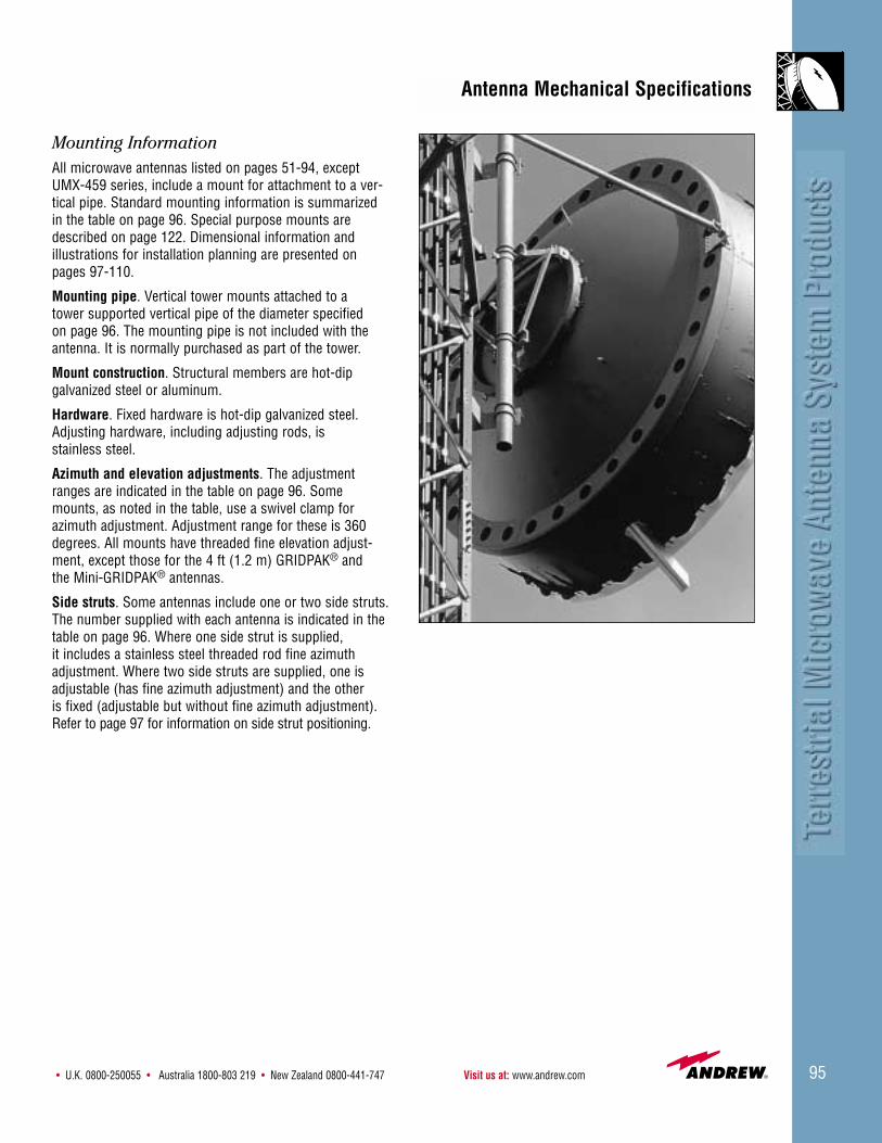
• U.K. 0800-250055 • Australia 1800-803 219 • New Zealand 0800-441-747 Visit us at: www.andrew.com 95
Mounting InformationAll microwave antennas listed on pages 51-94, except UMX-459 series, include a mount for attachment to a ver-tical pipe. Standard mounting information is summarizedin the table on page 96. Special purpose mounts aredescribed on page 122. Dimensional information and illustrations for installation planning are presented onpages 97-110.
Mounting pipe. Vertical tower mounts attached to a tower supported vertical pipe of the diameter specified on page 96. The mounting pipe is not included with theantenna. It is normally purchased as part of the tower.
Mount construction. Structural members are hot-dip galvanized steel or aluminum.
Hardware. Fixed hardware is hot-dip galvanized steel.Adjusting hardware, including adjusting rods, is stainless steel.
Azimuth and elevation adjustments. The adjustmentranges are indicated in the table on page 96. Somemounts, as noted in the table, use a swivel clamp forazimuth adjustment. Adjustment range for these is 360degrees. All mounts have threaded fine elevation adjust-ment, except those for the 4 ft (1.2 m) GRIDPAK® and the Mini-GRIDPAK® antennas.
Side struts. Some antennas include one or two side struts.The number supplied with each antenna is indicated in thetable on page 96. Where one side strut is supplied, it includes a stainless steel threaded rod fine azimuthadjustment. Where two side struts are supplied, one isadjustable (has fine azimuth adjustment) and the other is fixed (adjustable but without fine azimuth adjustment).Refer to page 97 for information on side strut positioning.
Antenna Mechanical Specifications

Customer Service Center - Call toll-free from: • U.S.A., Canada and Mexico 1-800-255-147996
The vertical tower mounts listed below are included aspart of all new antennas. Mount type numbers are shownfor ordering replacement mounts.
Vertical Tower Mounts
Replacement Mount Fine Azimuth Fine ElevationAntenna Type Number Mounting Pipe Center Offset* Adjustment Adjustment Side StrutsSize, ft (m) Metric Standard Hardware Dia. in (mm) in (mm) Degrees Degrees Included
Shielded Antennas
4 (1.2) T6MSB 4.5 (115) 5.4 (137)** ±5 ±5 –
6 (1.8) T6MSC 4.5 (115) 5.4 (137)** ±5 ±5 1
8 (2.4) T10MSB 4.5 (115) 8.0 (200) left* ±5 ±5 2
10 (3.0) T10MSB 4.5 (115) 8.0 (200) left* ±5 ±5 2
12 (3.7) T12MSA†† 4.5 (115) 8.5 (215) left* ±5 ±5 2
15 (4.6) Integral 4.5 (115) 8.0 (200) right* ±5 ±3.6 1
Standard and Focal Plane Antennas
4 (1.2)‡ T6MSB 4.5 (115) 5.4 (137)** ±5 ±5 –
4 (1.2)‡‡ 46770A-2 4.5 (115) 5.4 (137)** *** ±5 –
6 (1.8)‡ T6MSB 4.5 (115) 5.4 (137)** ±5 ±5 –
6 (1.8)‡‡ 46770A-2 4.5 (115) 5.4 (137)** *** ±5 –
8 (2.4) T10MSB 4.5 (115) 8.0 (200) left* ±5 ±5 1
10 (3.0) T10MSB 4.5 (115) 8.0 (200) left* ±5 ±5 1
12 (3.7) T12MSA 4.5 (115) 8.5 (215) left* ±5 ±5 2
15 (4.6) Integral 4.5 (115) 8.0 (200) right* ±5 ±3.6 1
GRIDPAK® Antennas
4 (1.3) Integral 4.5 (115) 6.88 (175) *** ±15 –
6 (2) 140854 4.5 (115) 6.88 (175) *** ±5 –
8 (2.4) 140855 4.5 (115) 6.88 (175) ±5 ±5 1
10 (3) 140856 4.5 (115) 6.88 (175) ±5 ±5 1
13 (4) 140857 4.5 (115) 6.88 (175) ±5 ±5 2
* With respect to the mounting pipe viewed from the rear of the antenna. Can be reversed by inverting the mount or antenna.** Can be offset right or left without inverting the mount or antenna.*** 360° azimuth capability, no fine adjustment.†† UHX12-59 includes a bottom strut and requires a 10 ft (3 m) long mounting pipe.‡ Applies to antennas 3.5 GHz and higher. ‡‡ Applies to antennas 2.7 GHz and lower, except for FP antennas which use the T6MSB mount.
Note: Integral mounts consist of multiple type numbers. Contact Andrew for type numbers.

• U.K. 0800-250055 • Australia 1800-803 219 • New Zealand 0800-441-747 Visit us at: www.andrew.com 97
Mount or Ring(Inboard)
Fixed Strut±25 Horizontal Plane
±25 Vertical Plane
Adjustable Strut±25 Horizontal Plane
±5 Vertical Plane
Both Struts Shown Parallel to Antenna
Boresight Axis
Attachment Point on Antenna
Side Strut Positioning
Reflector Edge(Outboard)
25°
5°
Dimensional information and illustrations for installationplanning are presented on the following pages.
Side Strut Positioning
For maximum wind load capacity, side struts should beinstalled straight back to the tower. When this is not possible, the following guidelines apply:
When only one side strut is supplied, its angle should notexceed ±25° in the horizontal plane and ±5° in the verticalplane. See illustration for “adjustable strut”.
For antennas with two side struts, the adjustable strut canbe lowered or raised 5° from horizontal. The fixed sidestrut can be lowered or raised 25°. In the horizontal plane,both struts can be positioned at an angle up to 25°. See illustration at right. Further, the strut closest to themounting pipe may be positioned at an angle up to 35°,provided the sum of the angles for both struts does notexceed 50°.
Feed Orientation
All Andrew solid parabolic antennas are fed from the center of the reflector and include polarization adjustment.The polarizations are clearly marked with arrows on thefeed mounting hub. For single polarized antennas, thearrow is positioned up or down for vertical polarizationand right or left for horizontal polarization. See illustrations.
Dual polarized, waveguide fed antennas have both inputflanges in the same plane to ease the attachment of wave-guide. One input signal is rotated 90° inside the feed hornto provide cross polarization.
UHX® high performance antennas have asymmetricalpatterns with lower sidelobe levels on one side. For theseantennas, RPEs are prepared for the full 360°. The frequency coordinator can use the better half of theradiation pattern on either the right or the left side of theantenna to reduce potential interference. HSX and UHXfeed hubs use red to identify the better side. This side canbe placed either right or left or boresight. Therefore, it isnecessary for the frequency coordinator to specify “redright” or “red left” feed position.
The installer must be advised of the proper feed orienta-tion on all ultra high performance antennas and the proper polarization for single-polarized antennas.
Rear View
Vertically Polarized Antenna
Horizontally Polarized Antenna
Side View
Dual Polarized Antennas. Applies to Specified Types
Applies to: PXL-17 and -19 series, PX6 (except -107 -22 and -127),PXL6 (except -107, -122 and -127) PXL10-37, PXL8-37
High Performanceand Standard
UHX Waveguide Red Left
UHXCoaxial Red Left
UHX WaveguideRed Right
UHXCoaxial
Red Right
Dual Polarized Antennas. Except Those Specified Above.
5°25°25°25°
Antenna/Tower Interface
Rear View Side View
Rear View Side View
Rear View
Side View
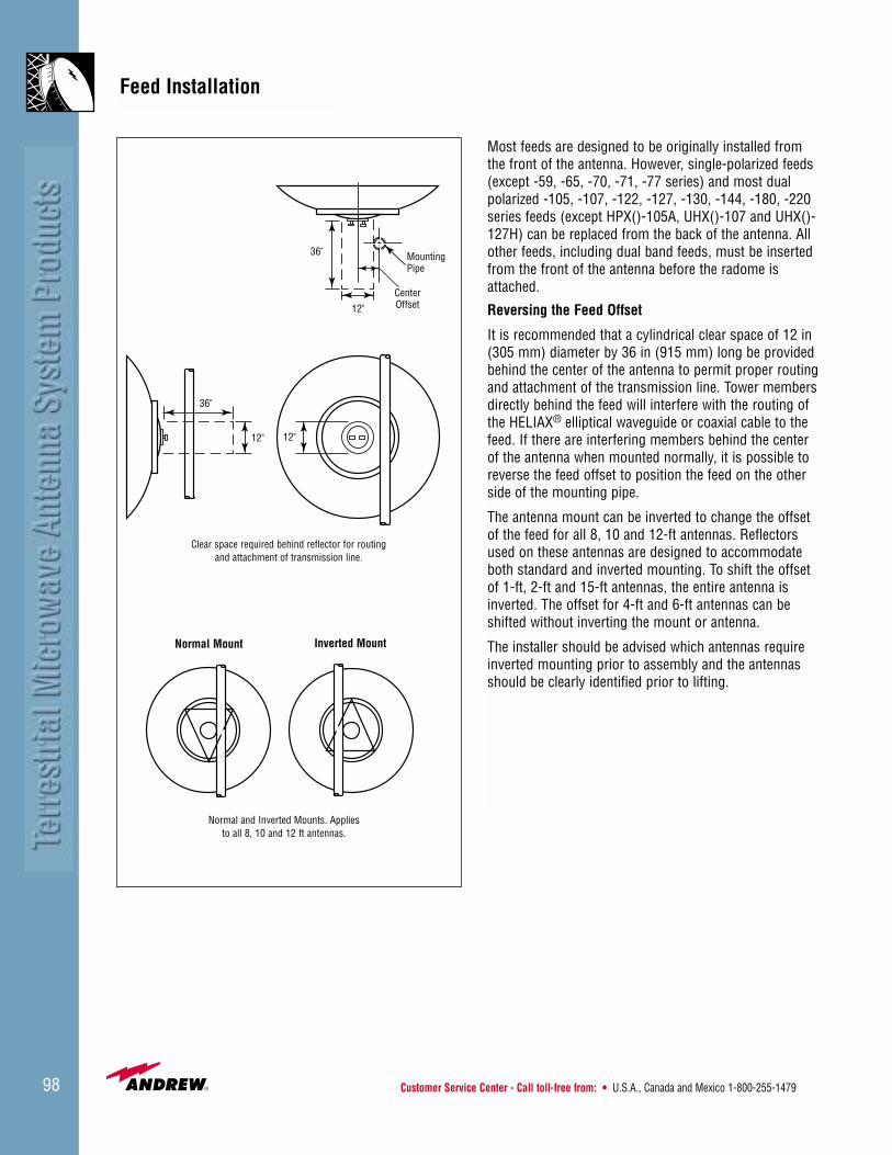
Customer Service Center - Call toll-free from: • U.S.A., Canada and Mexico 1-800-255-147998
Most feeds are designed to be originally installed from the front of the antenna. However, single-polarized feeds(except -59, -65, -70, -71, -77 series) and most dualpolarized -105, -107, -122, -127, -130, -144, -180, -220series feeds (except HPX()-105A, UHX()-107 and UHX()-127H) can be replaced from the back of the antenna. Allother feeds, including dual band feeds, must be insertedfrom the front of the antenna before the radome isattached.
Reversing the Feed Offset
It is recommended that a cylindrical clear space of 12 in(305 mm) diameter by 36 in (915 mm) long be providedbehind the center of the antenna to permit proper routingand attachment of the transmission line. Tower membersdirectly behind the feed will interfere with the routing ofthe HELIAX® elliptical waveguide or coaxial cable to thefeed. If there are interfering members behind the center of the antenna when mounted normally, it is possible toreverse the feed offset to position the feed on the otherside of the mounting pipe.
The antenna mount can be inverted to change the offset of the feed for all 8, 10 and 12-ft antennas. Reflectorsused on these antennas are designed to accommodateboth standard and inverted mounting. To shift the offset of 1-ft, 2-ft and 15-ft antennas, the entire antenna isinverted. The offset for 4-ft and 6-ft antennas can be shifted without inverting the mount or antenna.
The installer should be advised which antennas requireinverted mounting prior to assembly and the antennasshould be clearly identified prior to lifting.
MountingPipe
Normal Mount Inverted Mount
12"
Clear space required behind reflector for routingand attachment of transmission line.
Normal and Inverted Mounts. Appliesto all 8, 10 and 12 ft antennas.
Center Offset
36"
12"12"
36"
Feed Installation

• U.K. 0800-250055 • Australia 1800-803 219 • New Zealand 0800-441-747 Visit us at: www.andrew.com 99
The dimensions presented below are for use in planningtransmission line routing for waveguide, coaxial, single-polarized and dual-polarized feeds.
Dimensions D, F and G, in (mm)Antenna Type and Size, ft (m) D F G
Shielded Antennas
4 (1.2) 5.4 (140) 14.5 (370) 0.75 (19)6 (1.8) 5.4 (140) 11.75 (298) -0.6 (-15)8 and 10 (2.4 and 3.0) 8 (205) 13 (330) 1.1 (28)12 (3.7) 8.5 (215) 13 (330) 0.5 (13)15 (4.6) - 8 (-205) 15.25 (387) 8.1 (206)
Standard Antennas
4 (1.2) 5.4 (135) 11.75 (298) 0.75 (19)6 (1.8) 5.4 (135) 11.75 (298) -0.6 (-15)8 and 10 (2.4 and 3.0) 8 (205) 13 (330) 1.1 (28)12 (3.7) 8.5 (215) 13 (330) 0.5 (-13)15 (4.6) -8 (-205) 15.25 (387) 8.1 (206)
15 ft Antenna or6-12 ft Antenna with
Inverted Mount
Mounting Pipe
Top View
BD
EF
G
A
Applies to waveguide and coaxial, single and dual-polarized, except UMX® antennas
C
Dimensions A, B, C and EA = 4.5 in (115 mm)
B = 3 in (76 mm)
C = 1.5 in (38 mm)
E = F - (G + A)
Rear View
Feed Dimensions
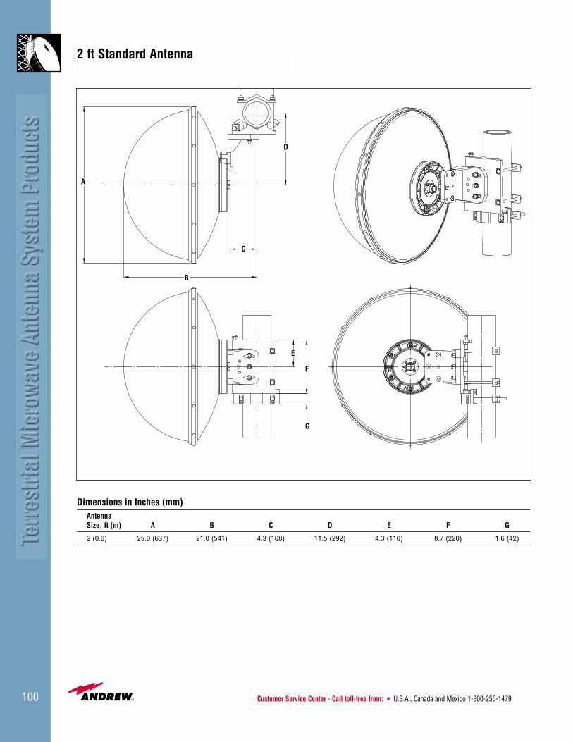
Customer Service Center - Call toll-free from: • U.S.A., Canada and Mexico 1-800-255-1479100
Dimensions in Inches (mm)Antenna Size, ft (m) A B C D E F G
2 (0.6) 25.0 (637) 21.0 (541) 4.3 (108) 11.5 (292) 4.3 (110) 8.7 (220) 1.6 (42)
2 ft Standard Antenna
D
C
B
A
E
F
G

• U.K. 0800-250055 • Australia 1800-803 219 • New Zealand 0800-441-747 Visit us at: www.andrew.com 101
A
B
C D
EF
G H
IBolt CircleDiameter
J
K
L
MNO
Top View
Rear View
Side View
Attachment Pointfor Adjusting Side Strut (6 ft Antennas) andOptional Side Strut (4 ft Antennas)
Azimuth AdjustmentAssembly (4 ft only)
Dimensions in Inches (mm)Antenna Size, ft (m) A B C D E F G H
4 (1.2) 52.4 (1330) 23.1 (585) 3.5 (90) 7.75 (195) 19.6 (500) 6.9 (175) 2.25 (55) 26.5 (675)6 (1.8) 76.5 (1945) 35.25 (895) 3.75 (95) 13.25 (335) 19.6 (500) 6.9 (175) 2.25 (55) 26.5 (675)
I J K L M N O
4 (1.2) 30.6 (780) 6.4 (160) – 11.62 (295) 29 (735) 21.5 (545) 19.25 (490)
6 (1.8) 30.6 (780) 6.4 (160) 84.75 (2155) 11.62 (295) 29 (735) 21.5 (545) 19.25 (490)
4 and 6 ft Shielded Antennas

Customer Service Center - Call toll-free from: • U.S.A., Canada and Mexico 1-800-255-1479102
Optional MoldedRadome
Note: Except for FP Type,2.7 GHz and Below
Antennas Do Not Have FineAzimuth Adjustments
Attachment Pointfor Optional Side Strut
4.5 in (115 mm) DiameterMounting Pipe (not included)
Side View
Top View
A
B
C
D
E
FG
H
I
JBolt CircleDiameter
K
L
M
4 and 6 ft Standard and Focal Plane Antennas
Rear View
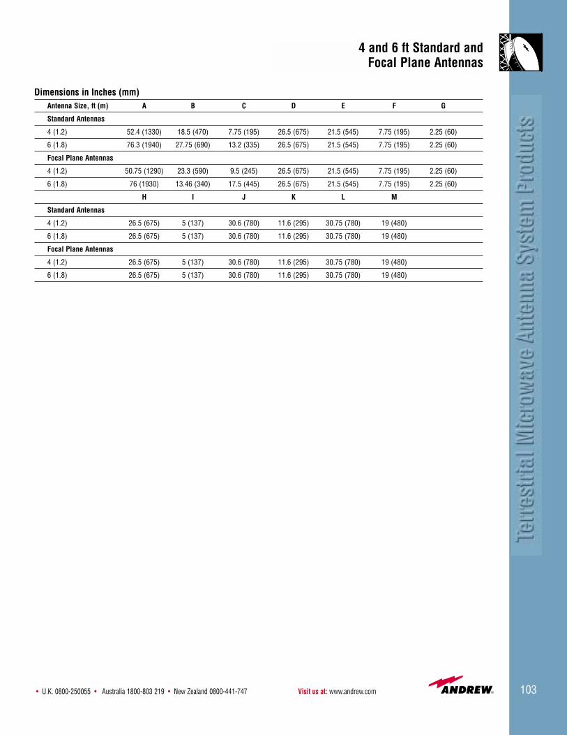
• U.K. 0800-250055 • Australia 1800-803 219 • New Zealand 0800-441-747 Visit us at: www.andrew.com 103
Dimensions in Inches (mm)Antenna Size, ft (m) A B C D E F G
Standard Antennas
4 (1.2) 52.4 (1330) 18.5 (470) 7.75 (195) 26.5 (675) 21.5 (545) 7.75 (195) 2.25 (60)
6 (1.8) 76.3 (1940) 27.75 (690) 13.2 (335) 26.5 (675) 21.5 (545) 7.75 (195) 2.25 (60)
Focal Plane Antennas
4 (1.2) 50.75 (1290) 23.3 (590) 9.5 (245) 26.5 (675) 21.5 (545) 7.75 (195) 2.25 (60)
6 (1.8) 76 (1930) 13.46 (340) 17.5 (445) 26.5 (675) 21.5 (545) 7.75 (195) 2.25 (60)
H I J K L M
Standard Antennas
4 (1.2) 26.5 (675) 5 (137) 30.6 (780) 11.6 (295) 30.75 (780) 19 (480)
6 (1.8) 26.5 (675) 5 (137) 30.6 (780) 11.6 (295) 30.75 (780) 19 (480)
Focal Plane Antennas
4 (1.2) 26.5 (675) 5 (137) 30.6 (780) 11.6 (295) 30.75 (780) 19 (480)
6 (1.8) 26.5 (675) 5 (137) 30.6 (780) 11.6 (295) 30.75 (780) 19 (480)
4 and 6 ft Standard and Focal Plane Antennas

Customer Service Center - Call toll-free from: • U.S.A., Canada and Mexico 1-800-255-1479104
AdjustingSide Strut
Optional MoldedRadome(Standard andFocal PlaneAntennas)
FixedSide Strut
Pipe 4-1/2"Diameter(115mm)
(not included)
Fixed Strut AttachmentPoint for 8, 10, and 12 ft Shielded and 12 ft Standard/FP Antennas
Optional Side StrutAttachment Point for 8 and 10 ft Standard/FPAntennas. Use Type520568 Bracket Kit (Order Separately)
Optional Bottom Strut Bracket for 8, 10 and 12 ft Two-Piece Reflectors
Optional Bottom Strut Bracket for 8, 10 and 12 ft One-Piece Reflectors
Adjusting StrutAttachment Point
8, 10 and 12 ftShielded and 12 ftStandard/FP Antennas(strut does not attachhere, except optionalside strut)
Optional Bottom StrutAttachment Point
Rear View
Side View
Top View
AB
C D
E
F G
H I
J K
L
MBolt Circle Diameter
N
PQ
R
S
T
25°
U
8, 10 and 12 ft Shielded, Standard and Focal Plane Antennas
25°
25°25°

• U.K. 0800-250055 • Australia 1800-803 219 • New Zealand 0800-441-747 Visit us at: www.andrew.com 105
Dimensions in Inches (mm)Antenna Size, ft (m) A B C D E F GShielded Antennas (Except Dual Beam with Extended Mount)
8 (2.4) 100.5 (2555) 106.5 (2705) 41.75 (1060) 5 (125) 15.5 (395) 59.75 (1520) 43.25 (1110)10 (3.0) 124.5 (3160) 130.5 (3315) 31.5 (800)** 5.5 (140) 24.25 (615) 71.75 (1820) 55.75 (1415)12 (3.7) 148.5 (3775) 154.5 (3915) 43 (1090)* 5.75 (145) 27 (685) 84.25 (2140) 67.25 (1710)
Dual Beam Antennas with Extended Mount (Sum and Difference)8 (2.4) 100.5 (2555) 106.5 (2705) 41.75 (1060) 5 (125) 15.5 (395) 62.75 (1595) 40.25 (1020)
10 (3.0) 124.5 (3160) 130.5 (3315) 31.5 (800) 5.5 (140) 24.25 (615) 74.75 (1900) 52.75 (1340)12 (3.7) 148.5 (3775) 154.5 (3915) 43 (1090) 5.75 (145) 27 (685) 86.75 (2205) 64.75 (1645)
Focal Plane Antennas8 (2.4) 100.5 (2555) 106.5 (2705) 26.5 (670) 5 (125) 21.5 (545) 59.75 (1520) 43.25 (1110)
10 (3.0) 124.5 (3160) 130.5 (3315) 36.25 (920) 5.5 (140) 29.5 (750) 71.75 (1820) 55.75 (1415)12 (3.7) 148.5 (3775) 154.5 (3915) 40.5 (1030) 5.75 (145) 35.5 (905) 84.25 (2140) 67.25 (1710)
Standard Antennas8 (2.4) 100.5 (2555) – 36 (915) 5 (125) 15.5 (395) – –
10 (3.0) 124.5 (3160) – 32.75 (830) 5.5 (140) 24.25 (615) 71.75 (1820) –12 (3.7) 148.5 (3775) 154.5 (3925) 36.5 (930) 5.75 (145) 27 (685) 84.25 (2140) 67.25 (1710)
H I J K L MShielded Antennas (Except Dual Beam with Extended Mount)
8 (2.4) 26.75 (680) 10.75 (275) 10.75 (275) 37.5 (950) 8 (200) 43.25 (1100)10 (3.0) 26.75 (680) 10.75 (275) 10.75 (275) 37.5 (950) 8 (200) 43.25 (1100)12 (3.7) 32.75 (835) 15.75 (400) 14 (355) 47.5 (1205) 8.5 (215) 56.25 (1430)
Dual Beam Antennas with Extended Mount (Sum and Difference)8 (2.4) 29.75 (755) 7.75 (195) 10.75 (275) 37.5 (950) 11.0 (280) 43.25 (1100)
10 (3.0) 29.75 (755) 7.75 (195) 10.75 (275) 37.5 (950) 11.0 (280) 43.25 (1100)12 (3.7) 35.25 (895) 13.25 (335) 14 (355) 47.5 (1205) 11.0 (280) 56.25 (1430)
Focal Plane Antennas8 (2.4) 26.75 (680) 10.75 (275) 10.75 (275) 37.5 (950) 8 (200) 43.25 (1100)
10 (3.0) 26.75 (680) 10.75 (275) 10.75 (275) 37.5 (950) 8 (200) 43.25 (1100)12 (3.7) 32.75 (835) 15.75 (400) 14 (355) 47.5 (1205) 8.5 (215) 56.25 (1430)
Standard Antennas8 (2.4) 26.75 (680) 10.75 (275) 10.75 (275) 37.5 (950) 8 (200) 43.25 (1100)
10 (3.0) 26.75 (680) 10.75 (275) 10.75 (275) 37.5 (950) 8 (200) 43.25 (1100)12 (3.7) 32.75 (835) 15.75 (400) 14 (355) 47.5 (1205) 8.5 (215) 56.25 (1430)
N P Q R S T UShielded Antennas (Except Dual Beam with Extended Mount)
8 (2.4) 13 (330) 37.5 (950) 35.25 (895) 24.5 (625) 27.25 (695) 120 (3050) 60 (1525)10 (3.0) 13 (330) 37.5 (950) 35.25 (895) 24.5 (625) 39.25 (1000) 120 (3050) 60 (1525)12 (3.7) 13 (330) 48.25 (1225) 45 (1145) 31 (790) 44.75 (1140) 120 (3050) 60 (1525)
Dual Beam Antennas with Extended Mount (Sum and Difference)8 (2.4) 20 (510) 37.5 (950) 35.25 (895) 24.5 (625) 27.25 (695) 120 (3050) 60 (1525)
10 (3.0) 20 (510) 37.5 (950) 35.25 (895) 24.5 (625) 39.25 (1000) 120 (3050) 60 (1525)12 (3.7) 20 (510) 48.25 (1225) 45 (1145) 31 (790) 44.75 (1140) 120 (3050) 60 (1525)
Focal Plane Antennas8 (2.4) 13 (330) 37.5 (950) 35.25 (895) 24.5 (625) 27.25 (695) 120 (3050) 60 (1525)
10 (3.0) 13 (330) 37.5 (950) 35.25 (895) 24.5 (625) 39.25 (1000) 120 (3050) 60 (1525)12 (3.7) 13 (330) 48.25 (1225) 45 (1145) 31 (790) 44.75 (1140) 120 (3050) 60 (1525)
Standard Antennas8 (2.4) 13 (330) 37.5 (950) 35.25 (895) 24.5 (625) 27.25 (695) 120 (3050) 60 (1525)
10 (3.0) 13 (330) 37.5 (950) 35.25 (895) 24.5 (625) 39.25 (1000) 120 (3050) 60 (1525)12 (3.7) 13 (330) 48.25 (1225) 45 (1145) 31 (790) 44.75 (1140) 120 (3050) 60 (1525)
* C = 57-1/4 in (1455 mm) for UHX12-59 ** C = 37.0 in (940 mm) for HDX10-107
8, 10 and 12 ft Shielded, Standard and Focal Plane Antennas

Customer Service Center - Call toll-free from: • U.S.A., Canada and Mexico 1-800-255-1479106
Adjustable Side StrutAttachment Point
A
BC
E
F
G
H
I
J
K
Side View
Rear View
Top View
Dimensions in Inches (mm)AntennaSize, ft (m) A B C D E F G H I J K
15 184.5 49.0 5.3 34.0 51.5 87 8 23.5 23.5 76.0 108(4.6) (4685) (1245) (135) (865) (1310) (2210) (200) (595) (595) (1930) (1240)
15 ft Shielded and Standard Antennas
D

• U.K. 0800-250055 • Australia 1800-803 219 • New Zealand 0800-441-747 Visit us at: www.andrew.com 107
Mounts to Pipe 2.3 in (60 mm) to
3.5 in (90 mm) in Diameter
MountingBracket
1/2" U-Bolt
Mini-GRIDPAK® Antennas
Side View Front View
DimensionsAntenna A B C D ESize, ft (m) in (mm) ft (m) in (mm) in (mm) ft (m)
6.6 x 3.3 (2 x 1) 5 (127) 6.6 (2) 15.4 (340) 37.0 (940) 5.3 (1)
Cable Entry tobe Facing Down
A
C
B
D
E
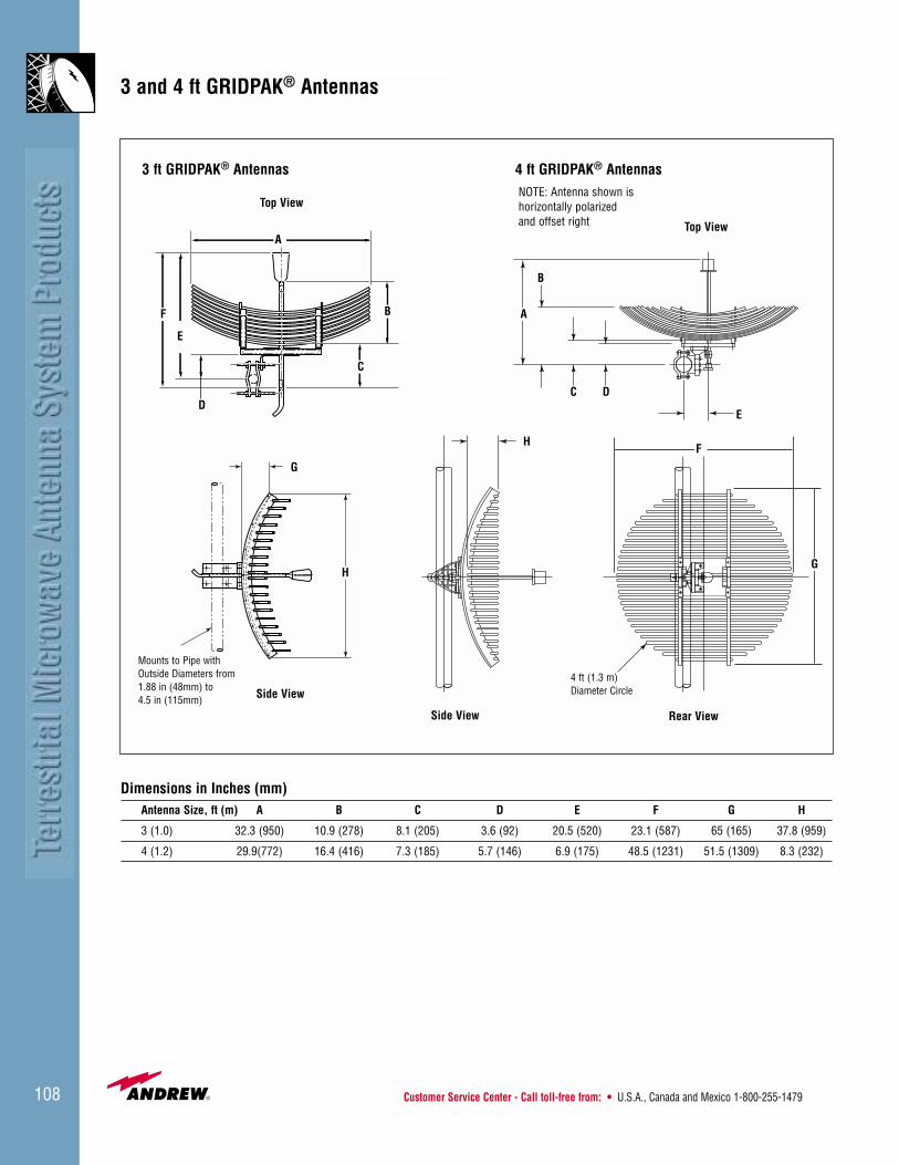
Customer Service Center - Call toll-free from: • U.S.A., Canada and Mexico 1-800-255-1479108
NOTE: Antenna shown ishorizontally polarizedand offset right Top View
Rear ViewSide View
4 ft (1.3 m)Diameter Circle
Mounts to Pipe withOutside Diameters from1.88 in (48mm) to 4.5 in (115mm) Side View
Top View
3 ft GRIDPAK® Antennas 4 ft GRIDPAK® Antennas
3 and 4 ft GRIDPAK® Antennas
A
B
C
D
E
F A
B
C D
E
G
H
HF
G
Dimensions in Inches (mm)Antenna Size, ft (m) A B C D E F G H
3 (1.0) 32.3 (950) 10.9 (278) 8.1 (205) 3.6 (92) 20.5 (520) 23.1 (587) 65 (165) 37.8 (959)
4 (1.2) 29.9(772) 16.4 (416) 7.3 (185) 5.7 (146) 6.9 (175) 48.5 (1231) 51.5 (1309) 8.3 (232)

• U.K. 0800-250055 • Australia 1800-803 219 • New Zealand 0800-441-747 Visit us at: www.andrew.com 109
6 ft GRIDPAK® Antennas
E
C
A
B
D
Dimensions in Inches (mm)Antenna Size, ft (m) A B C D E
6 (2.0) 41.3 (1049) 46.0 (1172) 8.0 (200) 81.0 (2061) 12.0 (304)
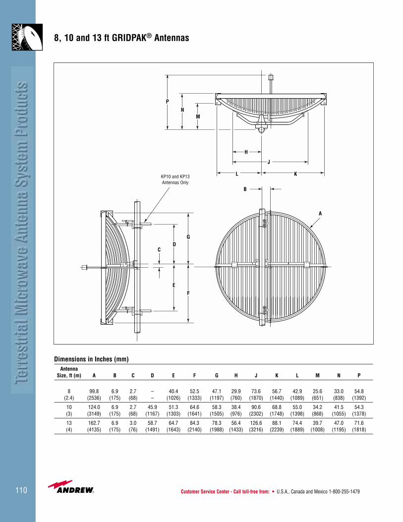
Customer Service Center - Call toll-free from: • U.S.A., Canada and Mexico 1-800-255-1479110
����
A
B
CD
EF
G
H
J
KL
MN
P
KP10 and KP13Antennas Only
Dimensions in Inches (mm)Antenna
Size, ft (m) A B C D E F G H J K L M N P
8 99.8 6.9 2.7 – 40.4 52.5 47.1 29.9 73.6 56.7 42.9 25.6 33.0 54.8(2.4) (2536) (175) (68) – (1026) (1333) (1197) (760) (1870) (1440) (1089) (651) (838) (1392)
10 124.0 6.9 2.7 45.9 51.3 64.6 58.3 38.4 90.6 68.8 55.0 34.2 41.5 54.3(3) (3149) (175) (68) (1167) (1303) (1641) (1505) (976) (2302) (1748) (1398) (868) (1055) (1378)
13 162.7 6.9 3.0 58.7 64.7 84.3 78.3 56.4 126.6 88.1 74.4 39.7 47.0 71.6(4) (4135) (175) (76) (1491) (1643) (2140) (1988) (1433) (3216) (2239) (1889) (1008) (1195) (1818)
8, 10 and 13 ft GRIDPAK® Antennas

• U.K. 0800-250055 • Australia 1800-803 219 • New Zealand 0800-441-747 Visit us at: www.andrew.com 111
Wind Forces
The axial, side and twisting moment forces tabulatedbelow and on page 112 are maximum values exerted on asupporting structure. They are the result of wind from themost critical direction for each parameter. The individualmaximums may not occur simultaneously. All forces arereferenced to the antenna mounting pipe. The components are:• Axial Force, FA• Side Force, FS• Twisting Moment, MT
Andrew software, included on thePowertools CD-ROM and downloadablefrom www.andrew.com, calculates theforces produced by winds from anyangle.
See page 44 for more information about Powertools.
Antenna Axis Wind
Top View
Parabolic Antennas
FA
MT
FS
Wind Forces at 125 mph (200 km/h)Antenna FA Max. FA Max. FS Max. FS Max. MT Max. MT Max. α For
Antenna Type Dia. ft (m) lb (N) lb (N) lb-ft (N•m) MT MaxShielded Antenna 4 (1.2) 634 2821 314 1398 -632 -826 -110With Planar Radome 6 (1.8) 1427 6348 707 3144 -1681 -2209 -110(Except “other shielded” 8 (2.4) 2537 11284 1257 5590 -3615 -4901 -110shown below) 10 (3.0) 3964 17632 1964 8734 -6365 -8630 -110
12 (3.7) 5708 25390 2827 12577 -10423 -14132 -11015 (4.6) 8919 39672 4418 19652 22000 29828 110
Other Shielded, With Planar RadomeUHX10-59 10 (3.0) 4000 17790 1910 8500 -6880 -9330 -105UMX10-459 10 (3.0) 4000 17790 1970 8760 -10100 -13700 -105HDX10-107 10 (3.0) 4040 17970 2065 9190 -7260 -9850 -105UHX12-59 12 (3.7) 5800 25800 3020 13430 -13610 -18450 -105UMX12-459 12 (3.7) 5760 25620 2830 12590 13400 18170 105UMX12-465 12 (3.7) 5910 26290 3210 14280 -15590 -21140 -105Focal Plane and PAR Series 4 (1.2) 918 4083 279 1240 -705 -937 -125Antenna without Radome 6 (1.8) 2065 9187 625 2790 -1936 -2635 -125
8 (2.4) 3672 16333 1115 4960 -4247 -5758 -12510 (3.0) 5737 25520 1742 7749 -7608 -10314 -12512 (3.7) 8261 36749 2509 11159 -12575 -17050 -125
Focal Plane and PAR Series 4 (1.2) 434 1930 267 1188 540 774 90Antennas with Radome* 6 (1.8) 976 4343 685 2673 1597 2309 100
8 (2.4) 1736 7720 1068 4751 3714 5036 9910 (3.0) 2712 12064 1669 7424 6883 9333 99
Standard Antenna 4 (1.2) 864 3843 236 1049 -647 -858 -130without Radome 6 (1.8) 1944 8647 531 2360 -1597 -2425 -130
8 (2.4) 3456 15372 943 4196 -3945 -5349 -12510 (3.0) 5400 24019 1474 6556 -7084 -9605 -12512 (3.7) 7775 34587 2122 9441 -11728 -15900 -12515 (4.6) 12149 54042 3316 14751 24294 32938 -125
Standard Antenna 2 (0.6) 109 483 67 297 94 128 -10with Radome 4 (1.2) 434 1930 267 1188 540 774 90
6 (1.8) 976 4343 685 2673 1597 2309 1008 (2.4) 1736 7720 1068 4751 3714 5036 99
10 ((3.0) 2712 12064 1669 7424 6883 9333 9912 (3.7) 3905 17372 2403 10691 11581 15702 99
GRIDPAK® Antenna 4 (1.3) 325 1450 190 840 351 475 60Without Ice KP Series 6 (2.0) 820 3650 430 1910 1342 1824 60
8 (2.4) 1180 5250 600 2670 2200 2990 6010 (3.0) 1825 8120 1020 4540 3869 5259 6013 (4.0) 3135 13940 1750 7780 8022 10903 60
*PAR series use deep reflectors on 6 ft - 8 ft only.
Forces Produced by Microwave Antennas
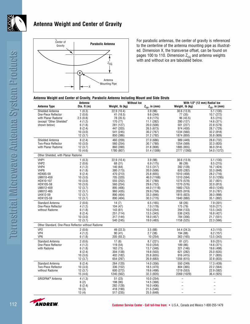
Customer Service Center - Call toll-free from: • U.S.A., Canada and Mexico 1-800-255-1479112
ZCG
X
AntennaMounting Pipe
Center ofGravity Parabolic Antenna
For parabolic antennas, the center of gravity is referencedto the centerline of the antenna mounting pipe as illustrat-ed. Dimension X, the transverse offset, can be found onpages 100 to 110. Dimension ZCG and antenna weightswith and without ice are tabulated below.
Antenna Weight and Center of Gravity, Parabolic Antenna Including Mount and Side StrutsAntenna Without Ice With 1/2" (12 mm) Radial Ice
Antenna Type Dia. ft (m) Weight, lb (kg) ZCG, in (mm) Weight, lb (kg) ZCG, in (mm)Shielded Antenna 1 (0.3) 22.9 (10.4) 3.9 (98) 30.6 (13.9) 5.1 (130)One-Piece Reflector 2 (0.6) 41 (18.5) 9.6 (244) 77 (35) 10.7 (272)with Planar Radome 2.5 (0.8) 78 (35.5) 6.9 (175) 96 (43.5) 8.5 (215)(except “Other Shielded” 4 (1.2) 170 (77) 11.1 (282) 280 (127) 14.6 (371)shown below) 6 (1.8) 281 (127) 20.0 (508) 501 (227) 22.8 (579)
8 (2.4) 447 (203) 26.5 (673) 974 (430) 28.7 (729)10 (3.0) 541 (245) 30.2 (767) 1234 (560) 32.2 (818)12 (3.7) 850 (386) 31.2 (792) 1874 (850) 35.8 (909)
Shielded Antenna 8 (2.4) 460 (209) 27.0 (686) 989 (449) 28.8 (732)Two-Piece Reflector 10 (3.0) 560 (254) 30.7 (780) 1254 (569) 32.3 (820)with Planar Radome 12 (3.7) 860 (390) 31.8 (808) 1885 (855) 36.0 (914)
15 (4.6) 1780 (807) 51.4 (1306) 2777 (1260) 54.0 (1372)Other Shielded, with Planar RadomeVHP1 1 (0.3) 22.9 (10.4) 3.9 (98) 30.6 (13.9) 5.1 (130)VHP2 2 (0.6) 68 (31) 6.9 (175) 86 (39) 8.5 (215)VHP4 4 (1.2) 140 (64) 12.5 (317) 282 (128) 16.7 (424)VHP6 6 (1.8) 380 (173) 20.0 (508) 620 (282) 33.3 (848)HDX8S-59 8 (2.4) 470 (213) 25.8 (655) 1010 (458) 28.2 (716)UMX10-459 10 (3.0) 705 (320) 46.0 (1168) 1310 (594) 51.0 (1295)HDX10-107 10 (3.0) 555 (252) 30.7 (780) 1275 (578) 32.7 (831)HDX10S-59 10 (3.0) 560 (254) 29.6 (752) 1270 (576) 32.0 (813)UMX12-459 12 (3.7) 895 (406) 44.0 (1118) 1660 (753) 49.0 (1245)UMX12-465 12 (3.7) 960 (435) 29.9 (759) 2025 (919) 31.0 (787)UHX12-59 12 (3.7) 890 (404) 33.3 (846) 1815 (823) 39.3 (998)HDX12S-59 12 (3.7) 890 (404) 30.3 (770) 1940 (880) 35.1 (892)Standard Antenna 2 (0.6) 14 (7) 6.5 (165) 58 (26) 7.9 (201)One-Piece Reflector 4 (1.2) 104 (47) 7.0 (178) 175 (79) 10.9 (277)without Radome 6 (1.8) 143 (61) 10.0 (254) 294 (133) 13.5 (343)
8 (2.4) 251 (114) 13.5 (343) 536 (243) 16.8 (427)10 (3.0) 317 (144) 18.0 (457) 784 (356) 21.7 (551)12 (3.7) 540 (245) 19.0 (483) 1158 (525) 22.3 (566)
Other Standard, One-Piece Reflector without RadomeVP2 2 (0.6) 49 (22.3) 3.5 (88) 54.4 (24.3) 4.3 (110)VP4 4 (1.2) 90 (41) 2.7 (38) 194 (88) 6.2 (157)VP6 6 (1.8) 205 (93.2) 10 (254) 363 (165) 13.5 (343)Standard Antenna 2 (0.6) 17 (8) 8.7 (221) 81 (37) 9.9 (251)One-Piece Reflector 4 (1.2) 119 (54) 10.0 (254) 189 (86) 14.6 (371)with Radome 6 (1.8) 162 (73) 13.7 (348) 321 (146) 19.6 (498)
8 (2.4) 304 (138) 19.8 (503) 621 (282) 25.0 (635)10 (3.0) 402 (182) 25.8 (655) 916 (415) 31.7 (805)12 (3.7) 654 (297) 26.9 (683) 1356 (615) 32.8 (833)
Standard Antenna 8 (2.4) 264 (120) 14.0 (356) 550 (249) 17.3 (439)Two-Piece Reflector 10 (3.0) 336 (152) 18.5 (470) 804 (365) 22.2 (564)without Radome 12 (3.7) 600 (272) 19.6 (498) 1219 (553) 22.9 (582)
15 (4.6) 1240 (562) 32.3 (820) 2269 (1029) 36.4 (925)GRIDPAK® Antenna 4 (1.3) 51 (23) 10.0 (254) – –
6 (2) 198 (90) 14.5 (368) – – 8 (2.4) 282 (128) 16.0 (406) – –
10 (3) 418 (190) 21.5 (546) – – 13 (4) 517 (235) 25.5 (648) – –
Antenna Weight and Center of Gravity
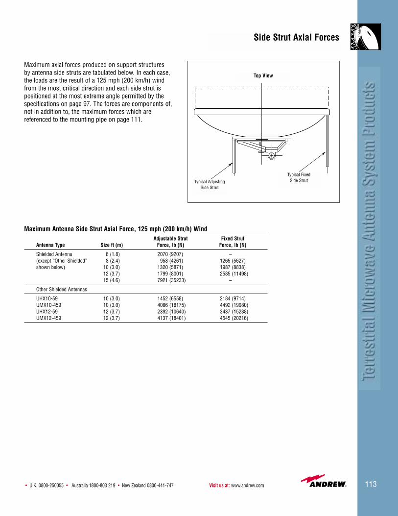
• U.K. 0800-250055 • Australia 1800-803 219 • New Zealand 0800-441-747 Visit us at: www.andrew.com 113
Maximum axial forces produced on support structures by antenna side struts are tabulated below. In each case,the loads are the result of a 125 mph (200 km/h) windfrom the most critical direction and each side strut ispositioned at the most extreme angle permitted by thespecifications on page 97. The forces are components of,not in addition to, the maximum forces which are referenced to the mounting pipe on page 111.
Typical AdjustingSide Strut
Typical FixedSide Strut
Top View
Maximum Antenna Side Strut Axial Force, 125 mph (200 km/h) WindAdjustable Strut Fixed Strut
Antenna Type Size ft (m) Force, lb (N) Force, lb (N)
Shielded Antenna 6 (1.8) 2070 (9207) – (except “Other Shielded” 8 (2.4) 958 (4261) 1265 (5627)shown below) 10 (3.0) 1320 (5871) 1987 (8838)
12 (3.7) 1799 (8001) 2585 (11498)15 (4.6) 7921 (35233) –
Other Shielded Antennas
UHX10-59 10 (3.0) 1452 (6558) 2184 (9714)UMX10-459 10 (3.0) 4086 (18175) 4492 (19980)UHX12-59 12 (3.7) 2392 (10640) 3437 (15288)UMX12-459 12 (3.7) 4137 (18401) 4545 (20216)
Side Strut Axial Forces

Customer Service Center - Call toll-free from: • U.S.A., Canada and Mexico 1-800-255-1479114
Antenna Options
UHX10-59 125 mph (200 km/h)
WUHX10-59 155 mph (250 km/h)
SUHX10-59 200 mph (320 km/h)
UHX10-59 Standard paint
EUHX10-59 Corrosive environment paint
WEUHX10-59 High wind and corrosive environment paint
All antenna orders require option codes to specify thedetails for your system. Most antennas include options forselecting feed input types, paint color, radome, packing,and environmental offerings. These option codes areunique characters placed before (prefix) or after (suffix)the base antenna type number. Prefix codes are optional.Suffix codes are required.
Prefix Option CodesThe prefix option codes include special environmentaloptions such as high wind and corrosive environment. For additional information about special environmentantennas, request Bulletin 3522.
High Wind Environment Options
High wind options that exceed the standard 125 mph (200 km/h) wind survival rating are available in 155 mph (250 km/h) and 200 mph (320 km/h) survival rating.These heavy duty antenna versions feature strong backstructures for maintaining alignment accuracy in adverseand severe wind conditions.
Use the “W” prefix for 155 mph (250 km/h), and the “S”prefix for 200 mph (320 km/h) survival ratings.
Corrosive Environment Options
The corrosive environment option is available for mostantennas. This option provides long term protection inmarine or salt and most industrial environments includingchemical and fossil fuel areas. A special epoxy paintapplied at the factory provides added protection. In addition, corrosion inhibiting compounds and protectivesealants are applied during installation.
Note: High wind and corrosive environment prefix codesare optional.
Suffix Option CodesSuffix option codes are required for your antenna order.The suffix option code is made up of three characters. The first character indicates the feed input type, the sec-ond character indicates the antenna color and applicableradome information, and the third character indicates thepacking options.

• U.K. 0800-250055 • Australia 1800-803 219 • New Zealand 0800-441-747 Visit us at: www.andrew.com 115
Antenna Options
The option code’s first character, indicating connector orflange type, has no default. You must specify a flange typefor each antenna ordered. The remaining option codes,indicating antenna color, radome, and packing, are option-al. If you do not specify a code for the second and thirdcharacters you will receive the default.
Note: Not all connector and flange types listed are applic-able for all antennas. Refer to the antenna input optionslisted in each antenna ordering table. Additional optionsavailable. Contact Andrew.
Antenna Input Option CodesCoaxial Applications
Connector Type Option Code
7/8" EIA E
“F” Flange Female F
7/16 DIN Female H
Type N Female N
Waveguide Applications
Flange Type Option Code
PBR B
PDR D
WR75 C
CPR P
UG* U
* Compatible with choke or cover
Antenna Color/Radome Option CodesAntenna Color Radome Type/Color* Option Code
Gray Hypalon/White 1
Gray TEGLAR®/White 3
Gray Not Available 7
Unpainted Not Available W (for GRIDPAK®)
Gray** Molded/Gray X
* All radomes listed have Andrew logo.** UNIPAK includes the radome and antenna in a single container.
Solid reflectors available for 2 ft to 10 ft, not available for 12 ft, 15 ft or any split two piece reflectors.For additional color information see pages 116-117.For additional radome information see pages 116-119.
Packing Option CodesPacking Option Code
Standard Global Pack A
Standard Global Pack for Two-Piece Split Reflector or GRIDPAK® M
Type Number with Option Code: UHX10-59-P
Description: UHX10-59 antenna with CPR flange
Type Number with Option Code: UHX10-59-P3
Description: UHX10-59 antenna with CPR flange, painted gray with white TEGLAR radome
Type Number with Option Code: UHX10-59-P3A
Description: UHX10-59 antenna with CPR flange, painted gray with white TEGLAR radome, Standard Global Pack

Customer Service Center - Call toll-free from: • U.S.A., Canada and Mexico 1-800-255-1479116
Radomes
Aviation Orange Green Brown Light Tan Gray Beige
Radomes
Radomes are available for most Andrew antennas.Radomes reduce wind loading to the tower while provid-ing added protection for the feed from the elements.There are two types of radomes, flexible and molded.Flexible radomes are provided on shielded antennas andmolded radomes are options to standard and focal planeantennas. All radomes have a standard minimum windsurvival of 125 mph (200 km/h).
Flexible Radomes
Flexible radomes are either Hypalon or TEGLAR® material.These materials are stretched and tensioned across theopening of the shield.* The radome flexes slightly in thewind, shedding ice and snow in most environments.
Hypalon is a rubber coated nylon material that is durableand suited for most normal environments. The standardcolor is white. Field painting is optional.
TEGLAR® is a polymer coated fiberglass material that pro-vides the greatest protection in harsh environments. Aspecial version of the TEGLAR radome is available withhigh wind series antennas. The standard color is white.Optional colors are available. TEGLAR radomes cannot befield painted.
* FPHP antennas include molded radomes. 4 ft (1.2 m) TEGLAR radomeis pre-tensioned.
Optional Colors
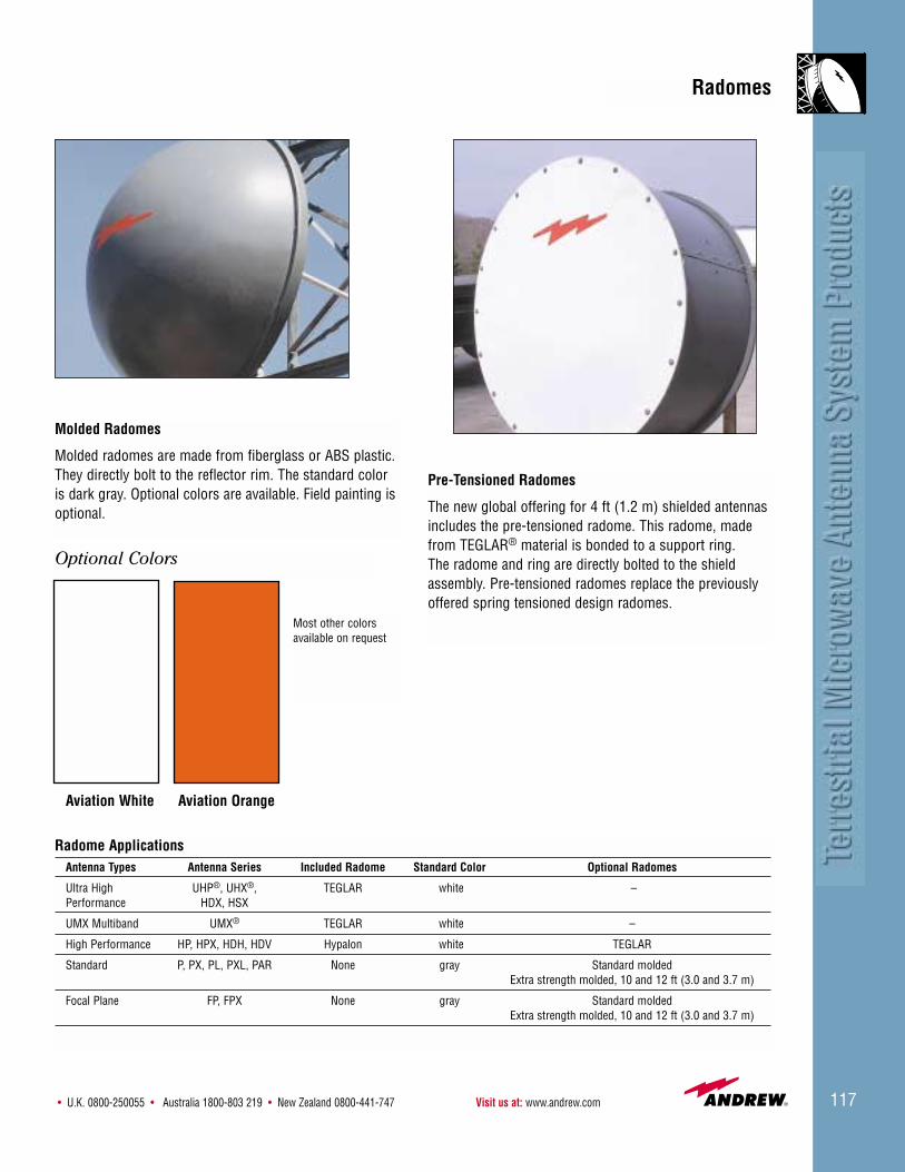
• U.K. 0800-250055 • Australia 1800-803 219 • New Zealand 0800-441-747 Visit us at: www.andrew.com 117
Radomes
Molded Radomes
Molded radomes are made from fiberglass or ABS plastic.They directly bolt to the reflector rim. The standard coloris dark gray. Optional colors are available. Field painting isoptional.
Pre-Tensioned Radomes
The new global offering for 4 ft (1.2 m) shielded antennasincludes the pre-tensioned radome. This radome, madefrom TEGLAR® material is bonded to a support ring. The radome and ring are directly bolted to the shieldassembly. Pre-tensioned radomes replace the previouslyoffered spring tensioned design radomes.
Radome ApplicationsAntenna Types Antenna Series Included Radome Standard Color Optional Radomes
Ultra High UHP®, UHX®, TEGLAR white –Performance HDX, HSX
UMX Multiband UMX® TEGLAR white –
High Performance HP, HPX, HDH, HDV Hypalon white TEGLAR
Standard P, PX, PL, PXL, PAR None gray Standard moldedExtra strength molded, 10 and 12 ft (3.0 and 3.7 m)
Focal Plane FP, FPX None gray Standard moldedExtra strength molded, 10 and 12 ft (3.0 and 3.7 m)
Aviation White Aviation Orange
Optional Colors
Most other colorsavailable on request
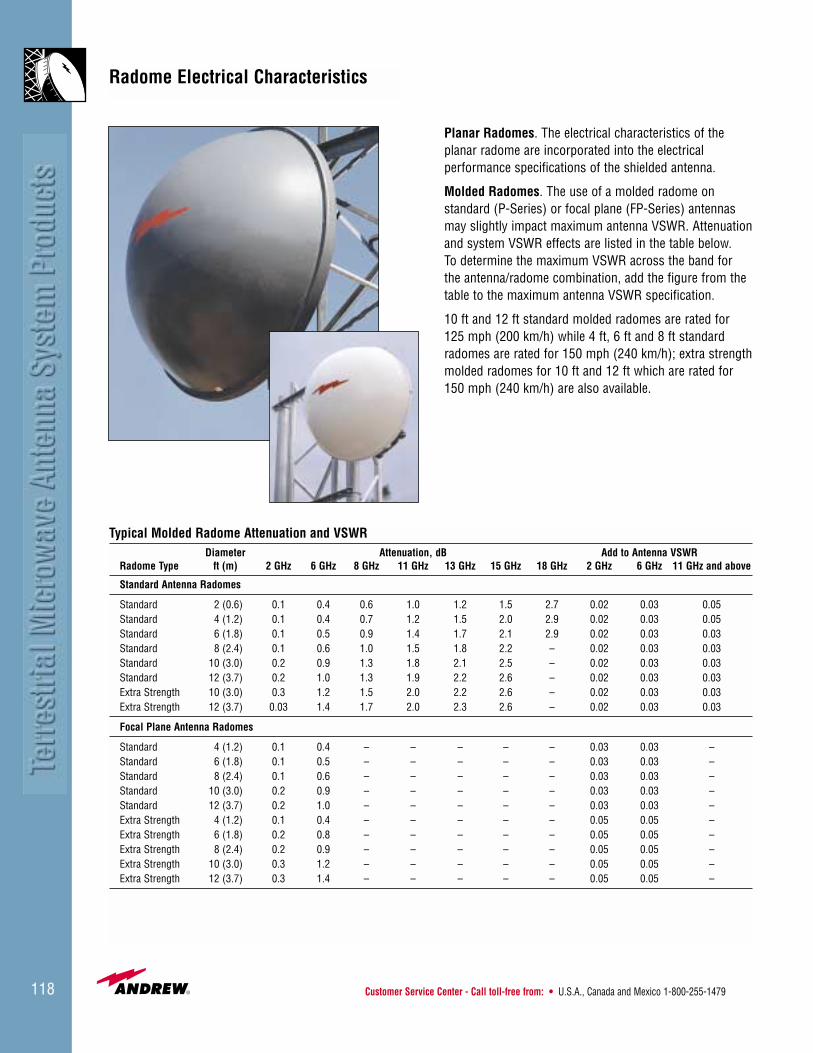
Customer Service Center - Call toll-free from: • U.S.A., Canada and Mexico 1-800-255-1479118
Radome Electrical Characteristics
Planar Radomes. The electrical characteristics of the planar radome are incorporated into the electrical performance specifications of the shielded antenna.
Molded Radomes. The use of a molded radome on standard (P-Series) or focal plane (FP-Series) antennasmay slightly impact maximum antenna VSWR. Attenuationand system VSWR effects are listed in the table below. To determine the maximum VSWR across the band for the antenna/radome combination, add the figure from thetable to the maximum antenna VSWR specification.
10 ft and 12 ft standard molded radomes are rated for 125 mph (200 km/h) while 4 ft, 6 ft and 8 ft standardradomes are rated for 150 mph (240 km/h); extra strengthmolded radomes for 10 ft and 12 ft which are rated for150 mph (240 km/h) are also available.
Typical Molded Radome Attenuation and VSWRDiameter Attenuation, dB Add to Antenna VSWR
Radome Type ft (m) 2 GHz 6 GHz 8 GHz 11 GHz 13 GHz 15 GHz 18 GHz 2 GHz 6 GHz 11 GHz and above
Standard Antenna Radomes
Standard 2 (0.6) 0.1 0.4 0.6 1.0 1.2 1.5 2.7 0.02 0.03 0.05Standard 4 (1.2) 0.1 0.4 0.7 1.2 1.5 2.0 2.9 0.02 0.03 0.05Standard 6 (1.8) 0.1 0.5 0.9 1.4 1.7 2.1 2.9 0.02 0.03 0.03Standard 8 (2.4) 0.1 0.6 1.0 1.5 1.8 2.2 – 0.02 0.03 0.03Standard 10 (3.0) 0.2 0.9 1.3 1.8 2.1 2.5 – 0.02 0.03 0.03Standard 12 (3.7) 0.2 1.0 1.3 1.9 2.2 2.6 – 0.02 0.03 0.03Extra Strength 10 (3.0) 0.3 1.2 1.5 2.0 2.2 2.6 – 0.02 0.03 0.03Extra Strength 12 (3.7) 0.03 1.4 1.7 2.0 2.3 2.6 – 0.02 0.03 0.03
Focal Plane Antenna Radomes
Standard 4 (1.2) 0.1 0.4 – – – – – 0.03 0.03 – Standard 6 (1.8) 0.1 0.5 – – – – – 0.03 0.03 –Standard 8 (2.4) 0.1 0.6 – – – – – 0.03 0.03 – Standard 10 (3.0) 0.2 0.9 – – – – – 0.03 0.03 – Standard 12 (3.7) 0.2 1.0 – – – – – 0.03 0.03 – Extra Strength 4 (1.2) 0.1 0.4 – – – – – 0.05 0.05 – Extra Strength 6 (1.8) 0.2 0.8 – – – – – 0.05 0.05 – Extra Strength 8 (2.4) 0.2 0.9 – – – – – 0.05 0.05 – Extra Strength 10 (3.0) 0.3 1.2 – – – – – 0.05 0.05 – Extra Strength 12 (3.7) 0.3 1.4 – – – – – 0.05 0.05 –

• U.K. 0800-250055 • Australia 1800-803 219 • New Zealand 0800-441-747 Visit us at: www.andrew.com 119
Radome Ordering Information
Current Model Antennas
Shielded antennas. All shielded antennas include aHypalon or TEGLAR® radome. Several antennas (HP andHPX) can be upgraded to TEGLAR for a minimal fee.
Standard and focal plane antennas. Standard and focalplane antennas* do not include a molded radome but inorder to reduce wind loading, one can be added to theantenna crate. The radome can be shipped with the anten-na using the UNIPAK shipping option. Specify the typenumber from the table below.
* FPHP antennas include radome
Older Model Antennas
Radome clip kits. Standard antennas (P-Series) reflectorwith a rolled rim manufactured prior to: September 1987for 4 ft (1.2 m) and 10 ft (3.0 m), February 1991 for 8 ft(2.4 m), and July 1991 for 6 ft (1.8 m) diameters requirethe additional clip kit listed in the table below.
Pre-tensioned radomes. For shielded 4 ft (1.2 m),TEGLAR spring-type attachment radomes have beenreplaced by pre-tensioned TEGLAR radomes that aredirectly attached to the rim of the shield. Field drilling is required. Type Number 520093-9
Standard molded radomes. The 2 ft (0.6 m) standard molded radome has changed in design. For antennasshipped prior to June 1998, request Type Number R2E.
Flexible planar radome replacement kits. These kitsinclude one radome and hardware to replace an existingAndrew planar radome. Specify the type number from thetable below.
Edge protection kit for TEGLAR® radomes. This kit pre-vents damage to the untensioned radome edge between J-bolt anchor points caused by unusually high gustingwinds. Kit includes stainless steel edge protector stripsand attachment hardware. The strips are fastened in pairsto form a band around the edge of the radome. Specifythe type number from the table below.
Radome Ordering InformationReflector Standard Extra Strength Focal Plane Extra Strength Edge ProtectionDiameter ft (m) Molded Molded Molded Focal Plane Molded Clip Kit Hypalon TEGLAR Kit (TEGLAR)
2 (0.6) R2E, VR2, VR2-WH – – – – – 207105*** –
4 (1.2) R4E R4E FR4 FR4-E 207844-1 – 207106** –520093-9*
6 (2.0) R6E R6E FR6 FR6-E 207844-2 520434-1 45665-1 205866-3
8 (2.4) R8F R8F FR8 FR8-E 207844-3 520434-2 45665-2 205866-4
10 (3.0) R10G 39193B FR10 FR10-E 207844-4 520434-3 45665-3 205866-1
12 (3.7) R12F 39194 FR12 FR12-E – 520434-4 45665-4 205866-2
15 (4.6) – – – – – 520434-5 45665-5 205866-5
* Pre-tensioned radome** Spring tensioned radome for older style antennas***Except 2 ft is gray
Revised 9/00

Customer Service Center - Call toll-free from: • U.S.A., Canada and Mexico 1-800-255-1479120
Heavy Duty Export Pack Dual PackStandard Pack
Packing TypeStandard Pack. In most cases, Andrew standard packingis suitable for export. Antennas are shipped as one unit.GRIDPAK® antennas and mounts are shipped in one carton or crate. 4-12 foot (1.2-3.7 m) radomes areshipped in wood crates.
Heavy Duty Export Pack. For your convenience, Andrewalso offers a heavy duty export packing option, whichincludes plywood sheathing of the entire antenna crate.This packing is suitable for ocean, container or air shipment. Multiple packing is also available which will provide considerable savings to the customer.
Dual Pack. Two antennas are packaged together in onecrate, reducing overall shipping volume.
Packing Quantity10-foot (3.0 m) and larger antennas and molded radomesmay require special handling in shipping, depending ondestination and routing. For systems requiring a largenumber of antennas, special packs can be quoted toreduce shipping volume. For example, it is often conve-nient to pack all antennas for the same site in the samebox. Andrew can also provide bulk transport and on-siteassembly of antennas.
For more details about crate dimensions and approximateweights, consult the price list for this catalog.
4 - 6 - 8 ft Standard Radome Pack
4 ft Shielded Antenna Pack
Antenna Packing

• U.K. 0800-250055 • Australia 1800-803 219 • New Zealand 0800-441-747 Visit us at: www.andrew.com 121
12 ft (split) Antenna Pack
6 ft Shielded Antenna Pack
8 - 10 ft Shielded Antenna Pack
KP Series GRIDPAK® Antenna Pack
Antenna Packing
UNIPAK

Customer Service Center - Call toll-free from: • U.S.A., Canada and Mexico 1-800-255-1479122
One piece reflectorGRIDPAK® disassembled Two piece reflector
Reflector TypeOne and Two-Piece Antennas. Antennas are suppliedwith one-piece reflectors or with two-piece reflectors splitthrough the center and bolted together at the site. GRIDPAK® and Mini-GRIDPAK antennas are supplied with reflectors that are completely disassembled.Standard and optional reflector types are dependent onantenna size and type. Refer to the table.
Special Purpose MountsIn addition to the standard mounts listed on page 96,Andrew can provide horizontal and vertical tilt mounts andother mount options to meet most special requirements.Contact Andrew for further information.
Standard and Optional ReflectorsReflector Type
Antenna Diameter Standard Optional
Solid Antennas - Standard, High Performance and Ultra High Performance
2-6 ft (0.3-1.8 m) One-Piece –
8-10 ft (2.4-3.0 m) One-Piece Two-Piece
12 ft (3.7 m) Two-Piece One-Piece
15 ft (4.6 m) Two-Piece –
GRIDPAK and Mini GRIDPAK Antennas - KP, KPR, MKP Series
All Reflector shipped –Disassembled

• U.K. 0800-250055 • Australia 1800-803 219 • New Zealand 0800-441-747 Visit us at: www.andrew.com 123
Additional Struts for Microwave AntennasFixed and Adjustable Side Struts provide increased rigidity. They can be added to any of the antennas, as indicated in the table, as a first or second strut.
Bottom Struts are recommended for high ice load environments. Requires mounting pipe which extends to bottom edge of antenna.
Attachment of Strut to AntennaThe strut attaches either to a bracket at the antenna rim or to the antenna mounting ring. See illustration.
Attachment at Antenna Rim8 through 12 ft Sizes
Attachment at Antenna Mounting Ring4 and 6 ft Sizes
Reflector Rim
Strut Mounting Bracket-520568 (supplied with
8-12 ft shielded antennasand standard 12 ft antennas)
Optional Fixed StrutKit-520570-4
Attach Optional FixedStrut Here
Antenna Mounting Ring
Optional FixedStrut Kit-
520570-1 or520570-2
Antenna Accessories
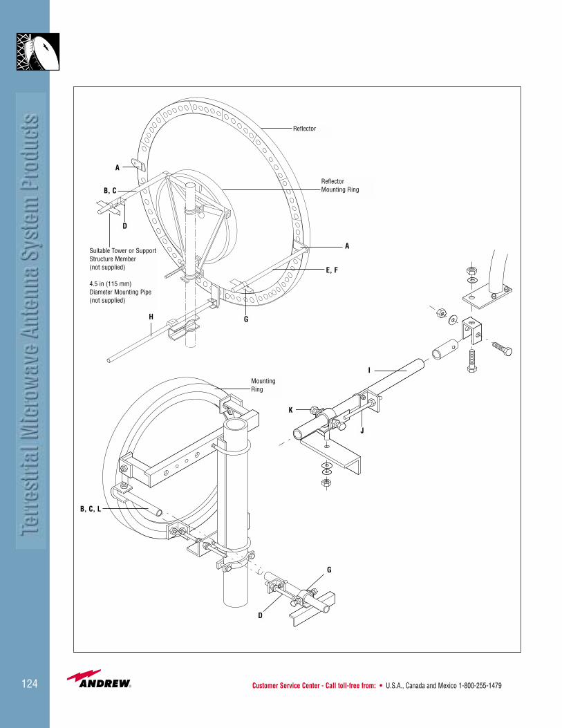
Customer Service Center - Call toll-free from: • U.S.A., Canada and Mexico 1-800-255-1479124
A
B, C
D
H G
E, F
ASuitable Tower or Support Structure Member (not supplied)
4.5 in (115 mm) Diameter Mounting Pipe (not supplied)
Reflector
ReflectorMounting Ring
J
I
K
MountingRing
B, C, L
D
G

• U.K. 0800-250055 • Australia 1800-803 219 • New Zealand 0800-441-747 Visit us at: www.andrew.com 125
A Reflector Strut Brackets, Type Number 520568 (replaces 44695)
Two brackets attach to the edge of 8 ft, 10 ft, and 12 ft reflectors to provide an attachment point for the fixed side strut. Brackets are cast aluminum and the kit contains all (metric) stainless steel hardware forattachment to the reflector. Quantity: 2 per kit.
B Adjustable Inboard Strut Kit, Type Number 520570-1 (replaces 221865) Solid reflector for the 12 ft.
Azimuth wind brace with threaded rod adjustment assembly allows for fine antenna alignment and lock down. Galvanized steel pipe and brackets include all (metric) galvanized hardware for attachment to antennamount or reflector mounting ring. Also includes item D, and G for tower end attachment. Strut pipe is schedule 80, and 10.5 ft (3.2 m) in length.
C Inboard Strut Kit (less azimuth adjustment), Type Number 520570-2
Typically used as an optional side strut for 4 ft (1.2 m) and 6 ft (1.8 m) reflectors same as B less item D. Includes strut and strut collar assembly (G).
D Azimuth Adjustment Kit, Type Number 520569 (replaces 40186-2)
Attaches to inboard side strut (and strut collar assembly) to allow fine movement of the antenna during final alignment. Straight (metric) threaded rod assembly and associated hardware included. Order strut collar clamp (G) separately.
E Outboard Strut Kit, Type Number 520570-3
Galvanized fixed side strut provides increased rigidity. Kit includes universal joint and (metric) hardware for attachment to reflector strut bracket (item A) included. Strut collar assembly (item G) also included to provide interface to tower. Strut pipe is schedule 80 and 10.5 ft (3.2m) in length.
F Outboard Strut Replacement Kit, Type Number 520570-4 (replaces 38891A)
Includes item G less item A reflector bracket.
G Strut Collar Assembly, Type Number 520477 (replaces 222944)
Provides tower interface and strut securement point. Galvanized clamp assembly includes stainless and galvanized hardware. (See tower interface options).
H Bottom Strut Kit, Type Number 520570-5 (replaces 40604)
Provides additional support to antennas due to weight of high ice loads. Reflector strut bracket, galvanized strut pipe, strut collar assembly, and (pipe mount) angle interface bracket included. All associated (metric) hardware is galvanized. Strut is schedule 80 and 5.0 ft (1.52 m) in length. Existing (extended) antenna pipe mount is required for strut attachment.
I Grid Strut Kit (KP Series only), Type Number 100232-7 (for 8, 10 and 13 ft only)
Provides added support in either the azimuth or elevation plane. Reflector strut bracket, strut pipe, strut collar assembly and hardware. All parts are galvanized including hardware. Strut is schedule 80 and 10.0 ft (3.05 m) in length. Order adjustment assembly separately, item J.
J Fine Azimuth Adjustment Assembly for Grid Strut and Collar Clamp Assembly, Type Number 100093-2
All parts galvanized including hardware.
K Grid Clamp Assembly, Type Number 100094
For replacement of item I and use with item J. All partsare galvanized including hardware.
L Short Strut Assembly, Type Number 520570-7
Short strut assembly for 6 ft (2.0 m) standard antennas allows strut packed within shipping crate. Includes hardware for attachment to antenna and tower. Strut is 83.5 in (1212 mm).
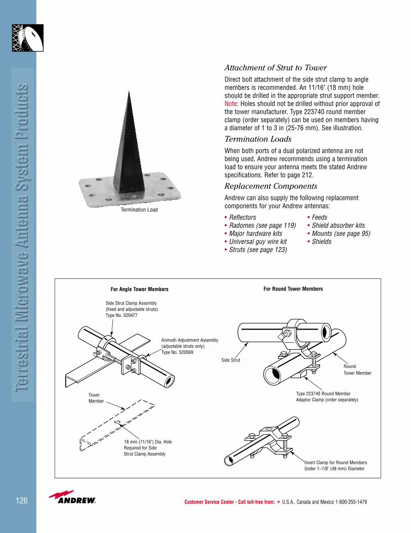
Customer Service Center - Call toll-free from: • U.S.A., Canada and Mexico 1-800-255-1479126
Attachment of Strut to TowerDirect bolt attachment of the side strut clamp to anglemembers is recommended. An 11/16" (18 mm) holeshould be drilled in the appropriate strut support member.Note: Holes should not be drilled without prior approval ofthe tower manufacturer. Type 223740 round memberclamp (order separately) can be used on members havinga diameter of 1 to 3 in (25-76 mm). See illustration.
Termination LoadsWhen both ports of a dual polarized antenna are not being used, Andrew recommends using a termination load to ensure your antenna meets the stated Andrew specifications. Refer to page 212.
Replacement ComponentsAndrew can also supply the following replacement components for your Andrew antennas:
• Reflectors • Feeds• Radomes (see page 119) • Shield absorber kits• Major hardware kits • Mounts (see page 95)• Universal guy wire kit • Shields• Struts (see page 123)
For Round Tower Members
Type 223740 Round MemberAdaptor Clamp (order separately)
Invert Clamp for Round MembersUnder 1–7/8" (48 mm) Diameter
RoundTower Member
Side Strut
18 mm (11/16") Dia. HoleRequired for SideStrut Clamp Assembly
TowerMember
Azimuth Adjustment Assembly(adjustable struts only)Type No. 520569
Side Strut Clamp Assembly(fixed and adjustable struts)Type No. 520477
For Angle Tower Members
Termination Load

• U.K. 0800-250055 • Australia 1800-803 219 • New Zealand 0800-441-747 Visit us at: www.andrew.com 127
ValuLine® Antennas
A Cost-Effective Antenna Solution forToday’s Terrestrial Microwave SystemsValuLine® antennas provide a cost-effective solution forall terrestrial microwave systems operating at frequenciesbetween 7 GHz and 60 GHz. The ValuLine range includesboth High Performance shielded antennas (VHP Series)and Standard performance unshielded antennas (VP Series). These antennas are available in both singleand dual polarized configurations and in sizes from 1 ft (0.3 m) to 6 ft (1.8 m) in diameter.
Andrew ValuLine antennas economically satisfy therequirements of the cellular, PCS/PCN, broadcast, and private user microwave applications, while still deliveringthe superior performance and overall quality expected ofAndrew. ValuLine antennas meet the regulatory require-ments of FCC, ETSI, RA, and BAPT and are qualified inmany countries including Russia, Brazil, and Poland.The antennas meet the requirements of the EIA195 and222 standards for electrical, mechanical, and structural characteristics, and are backed by a three-year warranty.
Fast, easy installation is made possible by the use of simple pole mounts, which can be attached to pipes withdiameters ranging from 1.9 inches (48 mm) to 4.5 inches(115 mm), depending on antenna type. Radome installa-tion on the 4 ft (1.2 m) and 6 ft (1.8 m) antennas is dramatically simplified by the use of rigid plastic radomes.Optionally, Andrew can supply these radomes painted tomatch local surroundings, minimizing their environmentalimpact.
Low Profile Antennas
To meet increasing demand for low visibility antenna systems, the ValuLine product range has been extended to include a new range of low profile shielded antennas
(VHLP Series) offering excellent electrical performance in an antenna with minimal environmental impact. Low profile antennas are available in frequencies from 13 GHz to 38 GHz and in sizes from 1 ft (0.3 m) to 4 ft (1.2 m) in diameter.
Flat Plate Antennas
The new ValuLine Flat Plate antennas provide the ultimatesolution for operators who require low visibility antennasfor short haul communications in areas such as congest-ed inner city sites. These antennas provide excellent pat-tern performance, normally only achieved by shieldedantennas, in a package less than 2 inches (46 mm) deep.This very low profile antenna, weighing less than 8 pounds (3.6 kg), reduces tower wind loading and is a cost-effective package for worldwide shipping.
Products are available in the 23 GHz, 27 GHz and 38 GHz 136 frequency bands.
Contact Andrew for further details.
Direct Antenna Radio Integration
Andrew has worked with the world’s leading radio housesto develop antennas that can be directly integrated withthe radio outdoor unit. These integrated antennas areavailable in all frequencies from 7 GHz to 38 GHz and insizes from 1 ft (0.3 m) to 6 ft (1.8 m) in diameter. Theseintegrated solutions, currently available for over 20 majorradio suppliers, provide a significant benefit in overall system cost.
Multiple Manufacturing Locations
In order to reduce shipping costs to sites worldwide,ValuLine antennas are available from Andrew locations inScotland, U.S.A., Brazil, and Australia. Standard Andrewdesigns and process controls ensure product consistencyand quality throughout the world.

Customer Service Center - Call toll-free from: • U.S.A., Canada and Mexico 1-800-255-1479128
ValuLine® Antenna Nomenclature
Andrew uses an alphanumeric numbering system foridentifying and ordering ValuLine antennas. Andrew type numbers describe the antenna type, size, regulatorycompliance, frequency band, catalog revision, and otheravailable options including flange type and VSWR specifi-cations, antenna and radome color, and packing andassembly information. This system is known worldwideand Andrew terminology is often used to specify antennawithin procurement documents.Example:
VHP 2 A - 220 A - 2 4 11 2 3 4 5 6 7 8
1 Antenna Type. The prefix is two, three, or four letters that describe the antenna type.
Use: To indicate:
VHP Shielded, Single PolarizedVHPX Shielded, Dual PolarizedVP Unshielded, Single PolarizedVHLP Low Profile, Single Polarized
2 Antenna Size. The number indicates the antenna diameter in feet.Use: To indicate:1 1 ft (0.3 m)2 2 ft (0.6 m)2.5 2.5 ft (0.8 m)4 4 ft (1.2 m)6 6 ft (1.8 m)
3 Regulatory Compliance.Use: To indicate:A Non-compliant to UK RA Specificationblank Compliant to UK RA Specification
4 Frequency Band. The numbers following the first hyphen are an abbreviated designation for the operating frequency band.
Use: To indicate:71 7.125-7.75 GHz71W 7.125-8.5 GHz74 7.425-7.9 GHz77 7.725-8.5 GHz102 10.2-10.7 GHz105 10.5-10.7 GHz107 10.7-11.7 GHz117 11.7-12.2 GHz130 12.75-13.25 GHz142 14.25-15.35 GHz159 15.9-16.5 GHz173 17.3-17.7 GHz1823 17.7-19.7 GHz/21.2-23.6 GHz180 17.7-19.7 GHz220 21.2-23.6 GHz240 24.25-26.5 GHz240W 24.25-29.5 GHz275 27.5-29.5 GHz275W 27.5-29.5 GHz/31.0-31.3 GHz310 31.0-31.8 GHz370 37.0-40.0 GHz490 49.2-50.2 GHz540 54.25-57.2 GHz570 57.2-58.2 GHz
5 Catalog Revision. This letter identifies product revisions. A change in revision letter indicates a change in electrical or mechanical specifications that affect antenna performance or the interface with other system equipment.
In addition, contact Andrew for details about these options:6 Antenna Flange Type and VSWR Specification.
See table on page 130.7 Antenna Appearance. This number identifies the
antenna color, radome color, and the presence of the Andrew flash.
8 Packing Type and Assembly Option. In the example above, VHP2A-220A-241 is:
1 ValuLine High Performance, shielded, single polarized2 2 ft (0.6 m) in diameter3 Non-compliant to UK RA specifications4 21.2-23.6 GHz band5 A Revision6 PBR220, 1.20 VSWR7 White Antenna, white radome, no flash8 Standard packing

• U.K. 0800-250055 • Australia 1800-803 219 • New Zealand 0800-441-747 Visit us at: www.andrew.com 129
E-Series ValuLine® Antennasfor Use in Extreme Environments
ValuLine® antennas are now available in upgraded versions that allow them to be used in locations subjected to high wind load or corrosive environments.
These antennas, available in diameters of 1 ft (0.3 m), 2 ft (0.6 m), 2.5 (0.8 m), 4 ft (1.2 m), and 6 ft (1.8 m),are mechanically upgraded to withstand 155 mph (250 km/h) through the use of additional struts andstrengthened reflectors.
The antennas also include additional treatments that willprovide long-term protection in marine, urban, and mostindustrial environments:
• Factory applied epoxy painting
• Hot-dip galvanizing
• Stainless steel hardware
• Corrosion inhibiting compounds
Contact Andrew for more information.
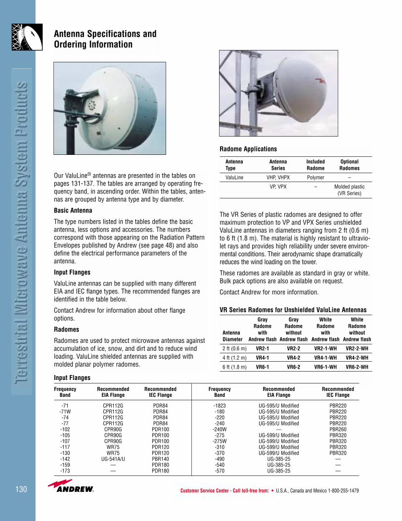
Customer Service Center - Call toll-free from: • U.S.A., Canada and Mexico 1-800-255-1479130
Antenna Specifications andOrdering Information
Our ValuLine® antennas are presented in the tables onpages 131-137. The tables are arranged by operating fre-quency band, in ascending order. Within the tables, anten-nas are grouped by antenna type and by diameter.
Basic Antenna
The type numbers listed in the tables define the basicantenna, less options and accessories. The numbers correspond with those appearing on the Radiation PatternEnvelopes published by Andrew (see page 48) and alsodefine the electrical performance parameters of the antenna.
Input Flanges
ValuLine antennas can be supplied with many differentEIA and IEC flange types. The recommended flanges areidentified in the table below.
Contact Andrew for information about other flangeoptions.
Radomes
Radomes are used to protect microwave antennas againstaccumulation of ice, snow, and dirt and to reduce windloading. ValuLine shielded antennas are supplied withmolded planar polymer radomes.
Radome Applications
Antenna Antenna Included OptionalType Series Radome Radomes
ValuLine VHP, VHPX Polymer –
VP, VPX – Molded plastic (VR Series)
The VR Series of plastic radomes are designed to offermaximum protection to VP and VPX Series unshieldedValuLine antennas in diameters ranging from 2 ft (0.6 m)to 6 ft (1.8 m). The material is highly resistant to ultravio-let rays and provides high reliability under severe environ-mental conditions. Their aerodynamic shape dramaticallyreduces the wind loading on the tower.
These radomes are available as standard in gray or white.Bulk pack options are also available on request.
Contact Andrew for more information.
VR Series Radomes for Unshielded ValuLine AntennasGray Gray White White
Radome Radome Radome RadomeAntenna with without with withoutDiameter Andrew flash Andrew flash Andrew flash Andrew flash
2 ft (0.6 m) VR2-1 VR2-2 VR2-1-WH VR2-2-WH
4 ft (1.2 m) VR4-1 VR4-2 VR4-1-WH VR4-2-WH
6 ft (1.8 m) VR6-1 VR6-2 VR6-1-WH VR6-2-WH
Input Flanges
Frequency Recommended Recommended Frequency Recommended RecommendedBand EIA Flange IEC Flange Band EIA Flange IEC Flange
-71 CPR112G PDR84 -1823 UG-595/U Modified PBR220-71W CPR112G PDR84 -180 UG-595/U Modified PBR220-74 CPR112G PDR84 -220 UG-595/U Modified PBR220-77 CPR112G PDR84 -240 UG-595/U Modified PBR220-102 CPR90G PDR100 -240W — PBR260-105 CPR90G PDR100 -275 UG-599/U Modified PBR320-107 CPR90G PDR100 -275W UG-599/U Modified PBR320-117 WR75 PDR120 -310 UG-599/U Modified PBR320-130 WR75 PDR120 -370 UG-599/U Modified PBR320-142 UG-541A/U PBR140 -490 UG-385-25 —-159 — PDR180 -540 UG-385-25 —-173 — PDR180 -570 UG-385-25 —

• U.K. 0800-250055 • Australia 1800-803 219 • New Zealand 0800-441-747 Visit us at: www.andrew.com 131
7.125 - 7.75 GHz (WR112 / R84)Fine Adjustment Survival Net
Type Diameter Gain, dBi Beamwidth Cross Pol. F/B Ratio VSWR max. degrees Wind Speed WeightNumber ft (m) Bottom Mid-Band Top degrees Disc., dB dB (R.L., dB) Azimuth Elevation mph (km/h) lb (kg)
VP2-71 2 (0.6) 30.6 31.0 31.4 4.9 30 40 1.15 (23.1)* ±15 ±50 155 (250) 19 (8.5)VP4-71 4 (1.2) 36.8 37.2 37.5 2.4 32 45 1.15 (23.1)* ±15 ±20 125 (200) 79 (36.0)VP6-71 6 (1.8) 40.5 40.9 41.3 1.6 32 49 1.15 (23.1)* ±5 ±5 125 (200) 160 (72.5)
VHP2-71 2 (0.6) 29.8 30.1 30.4 4.9 30 53 1.15 (23.1)* ±15 ±50 155 (250) 33 (15.0)VHP4-71 4 (1.2) 36.0 36.4 36.7 2.4 32 60 1.15 (23.1)* ±15 ±20 125 (200) 126 (57.0)VHP6-71 6 (1.8) 39.8 40.2 40.6 1.6 32 64 1.15 (23.1)* ±5 ±5 125 (200) 347 (157.5)
VHPX2-71 2 (0.6) 29.2 29.5 29.8 4.8 30 53 1.30 (17.7)** ±15 ±50 155 (250) 33 (15.0)VHPX4-71 4 (1.2) 35.9 36.3 36.6 2.4 32 60 1.15 (23.1)* ±15 ±20 125 (200) 126 (57.0)VHPX6-71 6 (1.8) 39.7 40.1 40.5 1.6 32 64 1.15 (23.1)* ±5 ±5 125 (200) 347 (157.5)
* 1.10 (26.4) available on request ** 1.25 (19.1) available on request
7.125 - 8.5 GHz (WR112 / R84)Fine Adjustment Survival Net
Type Diameter Gain, dBi Beamwidth Cross Pol. F/B Ratio VSWR max. degrees Wind Speed WeightNumber ft (m) Bottom Mid-Band Top degrees Disc., dB dB (R.L., dB) Azimuth Elevation mph (km/h) lb (kg)
VP2-71W 2 (0.6) 30.6 31.4 32.1 4.8 30 40 1.20 (20.8) ±15 ±50 155 (250) 19 (8.5)VP4-71W 4 (1.2) 36.8 37.5 38.3 2.3 32 45 1.15 (23.1) ±15 ±20 125 (200) 79 (36.0)VP6-71W 6 (1.8) 40.5 41.3 42.0 1.5 32 49 1.15 (23.1) ±5 ±5 125 (200) 160 (72.5)
VHP2-71W 2 (0.6) 29.8 30.4 31.1 4.9 30 54 1.15 (23.1) ±15 ±50 155 (250) 33 (15.0)VHP4-71W 4 (1.2) 36.0 36.6 37.5 2.4 32 62 1.15 (23.1) ±15 ±20 125 (200) 126 (57.0)VHP6-71W 6 (1.8) 39.7 40.5 41.2 1.7 32 66 1.15 (23.1) ±5 ±5 125 (200) 347 (157.5)
VHPX2-71W 2 (0.6) 29.2 29.8 30.4 4.8 30 53 1.30 (17.7) ±15 ±50 155 (250) 33 (15.0)VHPX4-71W 4 (1.2) 35.9 36.7 37.4 2.4 32 60 1.20 (20.8) ±15 ±20 125 (200) 126 (57.0)VHPX6-71W 6 (1.8) 39.7 40.5 40.7 1.7 32 64 1.20 (20.8) ±5 ±5 125 (200) 347 (157.5)
7.425 - 7.9 GHz (WR112 / R84)Fine Adjustment Survival Net
Type Diameter Gain, dBi Beamwidth Cross Pol. F/B Ratio VSWR max. degrees Wind Speed WeightNumber ft (m) Bottom Mid-Band Top degrees Disc., dB dB (R.L., dB) Azimuth Elevation mph (km/h) lb (kg)
VP2-74 2 (0.6) 31.0 31.2 31.5 4.8 30 40 1.15 (23.1)* ±15 ±50 155 (250) 19 (8.5)VP4A-74 4 (1.2) 37.2 37.4 37.7 2.3 32 45 1.15 (23.1)* ±15 ±20 125 (200) 79 (36.0)
VHP2-74 2 (0.6) 30.1 30.4 30.6 4.8 30 54 1.15 (23.1)* ±15 ±50 155 (250) 33 (15.0)VHP4A-74 4 (1.2) 36.4 36.6 36.9 2.3 32 62 1.15 (23.1)* ±15 ±20 125 (200) 126 (57.0)VHP4-74 4 (1.2) 36.2 36.4 36.7 2.3 32 62 1.15 (23.1)* ±15 ±20 125 (200) 126 (57.0)VHP6A-74 6 (1.8) 40.2 40.4 40.6 1.5 32 64 1.15 (23.1)* ±5 ±5 125 (200) 347 (157.5)
VHPX2A-74 2 (0.6) 29.5 29.7 29.9 4.7 30 53 1.30 (17.7)** ±15 ±50 155 (250) 33 (15.0)VHPX4A-74 4 (1.2) 36.3 36.5 36.8 2.4 32 60 1.15 (23.1)* ±15 ±20 125 (200) 126 (57.0)VHPX6A-74 6 (1.8) 40.1 40.3 40.5 1.5 32 64 1.15 (23.1)* ±5 ±5 125 (200) 347 (157.5)
* 1.10 (26.4) available on request ** 1.25 (19.1) available on request
Refer to pages 177 and 179 for Elliptical Waveguide ordering information

Customer Service Center - Call toll-free from: • U.S.A., Canada and Mexico 1-800-255-1479132
7.75 - 8.5 GHz (WR112 / R84)Fine Adjustment Survival Net
Type Diameter Gain, dBi Beamwidth Cross Pol. F/B Ratio VSWR max. degrees Wind Speed WeightNumber ft (m) Bottom Mid-Band Top degrees Disc., dB dB (R.L., dB) Azimuth Elevation mph (km/h) lb (kg)
VP2-77 2 (0.6) 31.3 31.7 32.1 4.6 30 40 1.15 (23.1)* ±15 ±50 155 (250) 19.0 (8.5)VP4-77 4 (1.2) 37.5 37.9 38.3 2.2 32 45 1.15 (23.1)* ±15 ±20 125 (200) 79.0 (36.0)VP6-77 6 (1.8) 41.3 41.7 42.0 1.5 32 50 1.15 (23.1)* ±5 ±5 125 (200) 160 (72.5)
VHP2-77 2 (0.6) 30.4 30.8 31.1 4.6 30 54 1.15 (23.1)* ±15 ±50 155 (250) 33 (15.0)VHP4-77 4 (1.2) 36.7 37.1 37.5 2.2 32 62 1.15 (23.1)* ±15 ±20 125 (200) 126 (57.0)VHP6-77 6 (1.8) 40.6 40.7 40.8 1.5 32 64 1.15 (23.1)* ±5 ±5 125 (200) 347 (157.5)
VHPX2-77 2 (0.6) 29.8 30.1 30.4 4.6 30 53 1.30 (17.7)** ±15 ±50 155 (250) 33 (15.0)VHPX4-77 4 (1.2) 36.6 37.0 37.4 2.2 32 60 1.15 (23.1)* ±15 ±20 125 (200) 126 (57.0)VHPX6-77 6 (1.8) 40.5 40.6 40.7 1.5 32 64 1.15 (23.1)* ±5 ±5 125 (200) 347 (157.5)
* 1.10 (26.4) available on request ** 1.25 (19.1) available on request
10.2 - 10.7 GHz (WR112 / R84)Fine Adjustment Survival Net
Type Diameter Gain, dBi Beamwidth Cross Pol. F/B Ratio VSWR max. degrees Wind Speed WeightNumber ft (m) Bottom Mid-Band Top degrees Disc., dB dB (R.L., dB) Azimuth Elevation mph (km/h) lb (kg)
VHP2-102 2 (0.6) 33.5 33.7 33.9 3.5 32 59 1.20 (20.8)* ±15 ±50 155 (250) 33 (15.0)VHP4-102 4 (1.2) 39.6 39.8 40.0 1.8 32 65 1.20 (20.8)* ±15 ±20 125 (200) 126 (57.0)VHP6-102 6 (1.8) 42.8 43.0 43.2 1.2 32 68 1.20 (20.8)* ±5 ±5 125 (200) 347 (157.5)
VHPX2-102 2 (0.6) 33.2 33.4 33.6 3.5 32 59 1.25 (19.1)** ±15 ±50 155 (250) 33 (15.0)VHPX4-102 4 (1.2) 39.4 39.6 39.8 1.8 32 65 1.25 (19.1)** ±15 ±20 125 (200) 126 (57.0)VHPX6-102 6 (1.8) 42.7 42.9 43.1 1.2 32 68 1.25 (19.1)** ±5 ±5 125 (200) 347 (157.5)
* 1.15 (23.1) available on request ** 1.20 (20.8) available on request
10.5 - 10.7 GHz (WR90 / R100)Fine Adjustment Survival Net
Type Diameter Gain, dBi Beamwidth Cross Pol. F/B Ratio VSWR max. degrees Wind Speed WeightNumber ft (m) Bottom Mid-Band Top degrees Disc., dB dB (R.L., dB) Azimuth Elevation mph (km/h) lb (kg)
VHP2-105 2 (0.6) 34.0 34.1 34.2 3.4 32 55 1.20 (20.8)* ±15 ±50 155 (250) 33 (15.0)VHP4-105 4 (1.2) 39.8 39.9 40.0 1.8 32 60 1.20 (20.8)* ±15 ±20 125 (200) 126 (57.0)VHP6-105 6 (1.8) 43.1 43.2 43.3 1.1 32 67 1.20 (20.8)* ±5 ±5 125 (200) 347 (157.5)
* 1.15 (23.1) available on request
10.7 - 11.7 GHz (WR90 / R100)Fine Adjustment Survival Net
Type Diameter Gain, dBi Beamwidth Cross Pol. F/B Ratio VSWR max. degrees Wind Speed WeightNumber ft (m) Bottom Mid-Band Top degrees Disc., dB dB (R.L., dB) Azimuth Elevation mph (km/h) lb (kg)
VHP4-107 4 (1.2) 40.1 40.5 40.9 1.8 32 60 1.20 (20.8)* ±15 ±20 125 (200) 126 (57.0)VHP6-107 6 (1.8) 43.3 43.6 43.9 1.1 32 67 1.20 (20.8)* ±5 ±5 125 (200) 347 (157.5)
* 1.15 (23.1) available on request
11.7 - 12.2 GHz (WR75 / R120)Fine Adjustment Survival Net
Type Diameter Gain, dBi Beamwidth Cross Pol. F/B Ratio VSWR max. degrees Wind Speed WeightNumber ft (m) Bottom Mid-Band Top degrees Disc., dB dB (R.L., dB) Azimuth Elevation mph (km/h) lb (kg)
VHP4-117 4 (1.2) 40.9 41.0 41.1 1.7 32 60 1.20 (20.8)* ±15 ±20 125 (200) 126 (57.0)
* 1.15 (23.1) available on request
Refer to pages 179 and 183 for Elliptical Waveguide ordering information
• U.K. 0800-250055 • Australia 1800-803 219 • New Zealand 0800-441-747 Visit us at: www.andrew.com 133
12.7 - 13.25 GHz (WR75 / R120)Fine Adjustment Survival Net
Type Diameter Gain, dBi Beamwidth Cross Pol. F/B Ratio VSWR max. degrees Wind Speed WeightNumber ft (m) Bottom Mid-Band Top degrees Disc., dB dB (R.L., dB) Azimuth Elevation mph (km/h) lb (kg)
VHP1-130 1 (0.3) 29.0 29.2 29.4 5.0 30 56 1.20 (20.8)* ±15 ±50 155 (250) 21 (9.7)VHP2-130 2 (0.6) 35.1 35.3 35.5 2.8 32 61 1.20 (20.8)* ±15 ±50 155 (250) 33 (15.0)VHP2.5-130 2.5 (0.8) 37.7 37.9 38.1 2.1 32 63 1.20 (20.8)* ±15 ±50 125 (200) 78 (35.5)VHP4-130 4 (1.2) 41.2 41.4 41.6 1.3 32 67 1.20 (20.8)* ±15 ±20 125 (200) 126 (57.0)VHP4A-130 4 (1.2) 41.2 41.4 41.6 1.3 32 63 1.20 (20.8)* ±15 ±20 125 (200) 126 (57.0)VHP6-130 6 (1.8) 44.8 45.0 45.1 0.9 32 70 1.20 (20.8)* ±5 ±5 125 (200) 347 (157.5)VHP6A-130 6 (1.8) 44.8 45.0 45.1 0.9 32 66 1.20 (20.8)* ±5 ±5 125 (200) 347 (157.5)
VHPX2-130 2 (0.6) 34.5 34.7 34.9 2.8 32 61 1.25 (19.1)** ±15 ±50 155 (250) 33 (15.0)VHPX2.5-130 2.5 (0.8) 37.2 37.5 37.7 2.1 32 63 1.25 (19.1)** ±15 ±50 125 (200) 78 (35.5)VHPX4-130 4 (1.2) 41.0 41.2 41.3 1.3 32 67 1.25 (19.1)** ±15 ±20 125 (200) 126 (57.0)VHPX4A-130 4 (1.2) 41.0 41.2 41.3 1.3 32 63 1.25 (19.1)** ±15 ±20 125 (200) 126 (57.0)VHPX6-130 6 (1.8) 44.6 44.8 44.9 0.9 32 70 1.25 (19.1)** ±5 ±5 125 (200) 347 (157.5)VHPX6A-130 6 (1.8) 44.6 44.8 44.9 0.9 32 66 1.25 (19.1)** ±5 ±5 125 (200) 347 (157.5)
VHLP2-130 2 (0.6) 35.3 35.5 35.7 2.5 30 61 1.30 (17.7) ±15 ±50 155 (250) 25 (11.3)VHLP2.5-130 2.5 (0.8) 37.6 37.8 38.0 2.1 30 63 1.30 (17.7) ±15 ±50 125 (200) 69 (31.2)VHLP4-130 4 (1.2) 41.3 41.5 41.7 1.3 30 67 1.30 (17.7) ±15 ±20 125 (200) 115 (52.0)
VP2A-130 2 (0.6) 35.3 35.5 35.7 2.8 32 45 1.20 (20.8)* ±15 ±50 155 (250) 19.0 (8.5)VP4A-130 4 (1.2) 41.4 41.6 41.8 1.3 32 52 1.20 (20.8)* ±15 ±20 125 (200) 79.0 (36.0)VP6A-130 6 (1.8) 45.0 45.2 45.3 0.9 32 58 1.20 (20.8)* ±5 ±5 125 (200) 160 (72.5)
* 1.15 (23.1) available on request ** 1.20 (20.8) available on request
14.25 - 15.35 GHz (WR62 / R140)Fine Adjustment Survival Net
Type Diameter Gain, dBi Beamwidth Cross Pol. F/B Ratio VSWR max. degrees Wind Speed WeightNumber ft (m) Bottom Mid-Band Top degrees Disc., dB dB (R.L., dB) Azimuth Elevation mph (km/h) lb (kg)
VHP1-142 1 (0.3) 30.8 31.1 31.4 4.5 30 50 1.20 (20.8)* ±15 ±50 155 (250) 21 (9.7)VHP2-142 2 (0.6) 36.2 36.5 36.8 2.4 32 62 1.20 (20.8)* ±15 ±50 155 (250) 33 (15.0)VHP2.5-142 2.5 (0.8) 38.8 39.1 39.4 1.8 32 64 1.20 (20.8)* ±15 ±50 125 (200) 78 (35.5)VHP4-142 4 (1.2) 42.2 42.5 42.8 1.2 32 68 1.20 (20.8)* ±15 ±20 125 (200) 126 (57.0)VHP4A-142 4 (1.2) 42.2 42.5 42.8 1.2 32 64 1.20 (20.8)* ±15 ±20 125 (200) 126 (57.0)VHP6-142 6 (1.8) 45.7 46.0 46.3 0.8 32 71 1.20 (20.8)* ±5 ±5 125 (200) 347 (157.5)VHP6A-142 6 (1.8) 45.7 46.0 46.3 0.8 32 67 1.20 (20.8)* ±5 ±5 125 (200) 347 (157.5)
VHPX2-142 2 (0.6) 36.0 36.3 36.6 2.4 32 62 1.25 (19.1)** ±15 ±50 155 (250) 33 (15.0)VHPX2.5-142 2.5 (0.8) 38.6 38.9 39.2 1.8 32 64 1.25 (19.1)** ±15 ±50 125 (200) 78 (35.5)VHPX4-142 4 (1.2) 42.0 42.3 42.6 1.2 32 68 1.25 (19.1)** ±15 ±20 125 (200) 126 (57.0)VHPX4A-142 4 (1.2) 42.0 42.3 42.6 1.2 32 64 1.25 (19.1)** ±15 ±20 125 (200) 126 (57.0)VHPX6-142 6 (1.8) 45.5 45.8 46.1 0.8 32 71 1.25 (19.1)** ±5 ±5 125 (200) 347 (157.5)VHPX6A-142 6 (1.8) 45.5 45.8 46.1 0.8 32 67 1.25 (19.1)** ±5 ±5 125 (200) 347 (157.5)
VHLP1-142 1 (0.3) 31.6 31.9 32.3 3.8 30 53 1.30 (17.7) ±15 ±50 155 (250) 18 (8.3)VHLP2-142 2 (0.6) 36.3 36.6 36.9 2.2 30 64 1.30 (17.7) ±15 ±50 155 (250) 25 (11.3)VHLP2.5-142 2.5 (0.8) 38.6 38.9 39.3 1.8 30 67 1.30 (17.7) ±15 ±50 125 (200) 69 (31.2)VHLP4-142 4 (1.2) 42.3 42.6 42.9 1.2 30 70 1.30 (17.7) ±15 ±20 125 (200) 115 (52.0)
VP2A-142 2 (0.6) 36.4 36.7 37.0 2.4 32 45 1.20 (20.8)* ±15 ±50 155 (250) 19.0 (8.5)VP4A-142 4 (1.2) 42.4 42.7 43.0 1.2 32 53 1.20 (20.8)* ±15 ±20 125 (200) 79.0 (36.0)VP6A-142 6 (1.8) 45.8 46.1 46.4 0.8 32 56 1.20 (20.8)* ±5 ±5 125 (200) 160 (72.5)
* 1.15 (23.1) available on request ** 1.20 (20.8) available on request
Refer to pages 185 and 187 for Elliptical Waveguide ordering information

Customer Service Center - Call toll-free from: • U.S.A., Canada and Mexico 1-800-255-1479134
15.9 - 16.5 GHz (WR51 / R180)Fine Adjustment Survival Net
Type Diameter Gain, dBi Beamwidth Cross Pol. F/B Ratio VSWR max. degrees Wind Speed WeightNumber ft (m) Bottom Mid-Band Top degrees Disc., dB dB (R.L., dB) Azimuth Elevation mph (km/h) lb (kg)
VP2-159 2 (0.6) 37.6 37.8 38.0 2 32 45 1.20 (20.8) ±15 ±50 155 (250) 19.0 (8.5)
17.3 - 17.7 GHz (WR51 / R180)Fine Adjustment Survival Net
Type Diameter Gain, dBi Beamwidth Cross Pol. F/B Ratio VSWR max. degrees Wind Speed WeightNumber ft (m) Bottom Mid-Band Top degrees Disc., dB dB (R.L., dB) Azimuth Elevation mph (km/h) lb (kg)
VHP1-173 1 (0.3) 32.4 32.5 32.6 3.8 30 58 1.20 (20.8)* ±15 ±50 155 (250) 21 (9.7)VHP2-173 2 (0.6) 38.0 38.1 38.2 2.3 32 64 1.20 (20.8)* ±15 ±50 155 (250) 33 (15.0)
VP4-173 4 (1.2) 44.1 44.2 44.3 1.0 32 55 1.20 (20.8)* ±15 ±20 125 (200) 79.0 (36.0)VP6-173 6 (1.8) 47.5 47.6 47.7 0.8 32 58 1.20 (20.8)* ±5 ±5 125 (200) 160 (72.5)
* 1.15 (23.1) available on request
17.7 - 19.7 GHz (WR42 / R220)Fine Adjustment Survival Net
Type Diameter Gain, dBi Beamwidth Cross Pol. F/B Ratio VSWR max. degrees Wind Speed WeightNumber ft (m) Bottom Mid-Band Top degrees Disc., dB dB (R.L., dB) Azimuth Elevation mph (km/h) lb (kg)
VHP1-180 1 (0.3) 32.6 33.1 33.5 3.6 30 58 1.20 (20.8)* ±15 ±50 155 (250) 21 (9.7)VHP2-180B 2 (0.6) 38.2 38.7 39.1 1.9 32 60 1.20 (20.8)* ±15 ±50 155 (250) 33 (15.0)VHP2.5-180 2.5 (0.8) 40.7 41.2 41.6 1.5 32 66 1.20 (20.8)* ±15 ±50 125 (200) 78 (35.5)VHP4-180A 4 (1.2) 44.1 44.6 45.1 0.9 32 65 1.20 (20.8)* ±15 ±20 125 (200) 126 (57.0)VHP6-180A 6 (1.8) 47.5 48.0 48.5 0.7 32 70 1.20 (20.8)* ±5 ±5 125 (200) 347 (157.5)
VHPX1-180 1 (0.3) 32.4 32.9 33.3 3.6 30 58 1.25 (19.1)** ±15 ±50 155 (250) 21 (9.7)VHPX2-180A 2 (0.6) 38.0 38.4 38.8 1.9 32 60 1.25 (19.1)** ±15 ±50 155 (250) 33 (15.0)VHPX2.5-180 2.5 (0.8) 40.5 41.0 41.4 1.5 32 66 1.25 (19.1)** ±15 ±50 125 (200) 78 (35.5)VHPX4-180A 4 (1.2) 44.0 44.5 45.0 0.9 32 65 1.25 (19.1)** ±15 ±20 125 (200) 126 (57.0)VHPX6-180A 6 (1.8) 47.4 47.9 48.4 0.7 32 70 1.25 (19.1)** ±5 ±5 125 (200) 347 (157.5)
VP2-180A 2 (0.6) 38.4 38.9 39.3 1.9 32 52 1.20 (20.8)* ±15 ±50 155 (250) 19.0 (8.5)VP4-180A 4 (1.2) 44.3 44.8 45.3 0.9 32 53 1.20 (20.8)* ±15 ±20 125 (200) 79.0 (36.0)VP6-180A 6 (1.8) 47.7 48.2 48.7 0.7 32 57 1.20 (20.8)* ±5 ±5 125 (200) 160 (72.5)
VHLP1-180 1 (0.3) 33.5 34.0 34.4 3.0 30 55 1.30 (17.7) ±15 ±50 155 (250) 18 (8.3)VHLP2-180 2 (0.6) 38.2 38.7 39.1 1.8 30 67 1.30 (17.7) ±15 ±50 155 (250) 25 (11.3)VHLP2.5-180 2.5 (0.8) 40.5 41.0 41.4 1.5 30 69 1.30 (17.7) ±15 ±50 125 (200) 69 (31.2)VHLP4-180 4 (1.2) 44.2 44.7 45.1 0.9 30 73 1.30 (17.7) ±15 ±20 125 (200) 115 (52.0)
* 1.15 (23.1) available on request * 1.20 (20.8) available on request
17.7 - 19.7 GHz / 21.2 - 23.6 GHz (WR42 / R220) Multiband AntennasFine Adjustment Survival Net
Type Diameter Gain, dBi Beamwidth Cross Pol. F/B Ratio VSWR max. degrees Wind Speed WeightNumber ft (m) Bottom Mid-Band Top degrees Disc., dB dB (R.L., dB) Azimuth Elevation mph (km/h) lb (kg)
VHP2-182317.7 - 19.7 GHz (0.6) 37.6 38.1 38.6 1.9 30 67 1.30 (17.7) ±15 ±50 155 (250) 33 (15.0)21.2 - 23.6 GHz (0.6) 39.2 39.6 40.0 1.5 30 64 1.30 (17.7)
VHP4-182317.7 - 19.7 GHz 4 (1.2) 43.7 44.2 44.7 0.9 30 68 1.30 (17.7) ±15 ±20 125 (200) 126 (57.0)21.2 - 23.6 GHz 4 (1.2) 45.2 45.7 46.2 0.8 30 70 1.30 (17.7)
Refer to pages 189 and 191 for Elliptical Waveguide ordering information

• U.K. 0800-250055 • Australia 1800-803 219 • New Zealand 0800-441-747 Visit us at: www.andrew.com 135
21.2 - 23.6 GHz (WR42 / R220)Fine Adjustment Survival Net
Type Diameter Gain, dBi Beamwidth Cross Pol. F/B Ratio VSWR max. degrees Wind Speed WeightNumber ft (m) Bottom Mid-Band Top degrees Disc., dB dB (R.L., dB) Azimuth Elevation mph (km/h) lb (kg)
VHP1-220 1 (0.3) 34.3 34.8 35.2 2.8 30 60 1.20 (20.8)* ±15 ±50 155 (250) 21 (9.7)VHP2-220A 2 (0.6) 39.6 40.1 40.5 1.6 32 66 1.20 (20.8)* ±15 ±50 155 (250) 33 (15.0)VHP2.5-220 2.5 (0.8) 42.1 42.6 43.1 1.4 32 68 1.20 (20.8)* ±15 ±50 125 (200) 78 (35.5)VHP4-220A 4 (1.2) 45.6 46.1 46.6 0.8 32 72 1.20 (20.8)* ±15 ±20 125 (200) 126 (57.0)VHP4A-220A 4 (1.2) 45.6 46.1 46.6 0.8 32 63 1.20 (20.8)* ±15 ±20 125 (200) 126 (57.0)VHP6-220A 6 (1.8) 48.9 49.4 49.9 0.5 32 75 1.20 (20.8)* ±5 ±5 125 (200) 347 (157.5)VHP6A-220A 6 (1.8) 48.9 49.4 49.9 0.5 32 72 1.20 (20.8)* ±5 ±5 125 (200) 347 (157.5)
VHPX1-220 1 (0.3) 33.7 34.2 34.6 2.8 30 60 1.25 (19.1)** ±15 ±50 155 (250) 21 (9.7)VHPX2-220A 2 (0.6) 39.4 39.9 40.3 1.6 32 66 1.25 (19.1)** ±15 ±50 155 (250) 33 (15.0)VHPX2.5-220 2.5 (0.8) 41.9 42.4 42.9 1.4 32 68 1.25 (19.1)** ±15 ±50 125 (200) 78 (35.5)VHPX4-220A 4 (1.2) 45.5 46.0 46.5 0.8 32 72 1.25 (19.1)** ±15 ±20 125 (200) 126 (57.0)VHPX4A-220A 4 (1.2) 45.5 46.0 46.5 0.8 32 63 1.25 (19.1)** ±15 ±20 125 (200) 126 (57.0)VHPX6-220A 6 (1.8) 48.8 49.3 49.8 0.5 32 75 1.25 (19.1)** ±5 ±5 125 (200) 347 (157.5)VHPX6A-220A 6 (1.8) 48.8 49.3 49.8 0.5 32 72 1.25 (19.1)** ±5 ±5 125 (200) 347 (157.5)
VP2-220 2 (0.6) 39.8 40.3 40.7 1.6 32 54 1.20 (20.8)* ±15 ±50 155 (250) 19.0 (8.5)VP4A-220 4 (1.2) 45.8 46.3 46.8 0.8 32 58 1.20 (20.8)* ±15 ±20 125 (200) 79.0 (36.0)
VHLP1-220 1 (0.3) 34.4 34.9 35.4 2.8 30 61 1.30 (17.7) ±15 ±50 155 (250) 18 (8.3)VHLP2-220 2 (0.6) 39.6 40.1 40.6 1.6 30 66 1.30 (17.7) ±15 ±50 155 (250) 25 (11.3)VHLP4-220 4 (1.2) 45.5 46.0 46.5 0.7 30 72 1.30 (17.7) ±15 ±20 125 (200) 115 (52.0)
* 1.15 (23.1) available on request ** 1.20 (20.8) available on request
24.25 - 26.5 GHz (WR42 / R220)Fine Adjustment Survival Net
Type Diameter Gain, dBi Beamwidth Cross Pol. F/B Ratio VSWR max. degrees Wind Speed WeightNumber ft (m) Bottom Mid-Band Top degrees Disc., dB dB (R.L., dB) Azimuth Elevation mph (km/h) lb (kg)
VHP1-240A 1 (0.3) 35.5 35.9 36.3 2.5 30 61 1.20 (20.8)* ±15 ±50 155 (250) 21 (9.7)VHP2-240A 2 (0.6) 40.6 41.0 41.4 1.4 32 67 1.20 (20.8)* ±15 ±50 155 (250) 33 (15.0)VHP2.5-240 2.5 (0.8) 43.2 43.6 44.0 1.1 32 69 1.20 (20.8)* ±15 ±50 125 (200) 78 (35.5)VHP4-240 4 (1.2) 46.5 46.9 47.2 0.7 32 73 1.20 (20.8)* ±15 ±20 125 (200) 126 (57.0)
VHPX1-240A 1 (0.3) 35.3 35.7 36.1 2.5 30 61 1.25 (19.1)** ±15 ±50 155 (250) 21 (9.7)VHPX2-240A 2 (0.6) 40.4 40.8 41.2 1.4 32 67 1.25 (19.1)** ±15 ±50 155 (250) 33 (15.0)VHPX2.5-240 2.5 (0.8) 43.0 43.4 43.8 1.1 32 69 1.25 (19.1)** ±15 ±50 125 (200) 78 (35.5)VHPX4-240 4 (1.2) 46.3 46.7 47.0 0.7 32 73 1.25 (19.1)** ±15 ±20 125 (200) 126 (57.0)
VHLP1-240 1 (0.3) 35.6 36.0 36.4 2.5 30 62 1.30 (17.7) ±15 ±50 155 (250) 18 (8.3)VHLP2-240 2 (0.6) 40.7 41.1 41.5 1.4 30 67 1.30 (17.7) ±15 ±50 155 (250) 25 (11.3)VHLP4-240 4 (1.2) 46.5 46.9 47.2 0.6 30 73 1.30 (17.7) ±15 ±20 125 (200) 115 (52.0)
VP2-240 2 (0.6) 40.8 41.2 41.6 1.5 32 52 1.20 (20.8)* ±15 ±50 155 (250) 19.0 (8.5)
* 1.15 (23.1) available on request ** 1.20 (20.8) available on request
Refer to pages 191 and 193 for Elliptical Waveguide ordering information
24.25 - 29.5 GHz (WR34 / R260)Fine Adjustment Survival Net
Type Diameter Gain, dBi Beamwidth Cross Pol. F/B Ratio VSWR max. degrees Wind Speed WeightNumber ft (m) Bottom Mid-Band Top degrees Disc., dB dB (R.L., dB) Azimuth Elevation mph (km/h) lb (kg)
VHP1-240W 1 (0.3) 35.8 36.5 37.1 2.5 30 62 1.20 (20.8)* ±15 ±50 155 (250) 21 (9.7)VHP2-240W 2 (0.6) 40.6 41.3 41.9 1.4 32 68 1.20 (20.8)* ±15 ±50 155 (250) 33 (15.0)
* 1.15 (23.1) available on request
Customer Service Center - Call toll-free from: • U.S.A., Canada and Mexico 1-800-255-1479136
27.5 - 29.5 GHz (WR28 / R320)Fine Adjustment Survival Net
Type Diameter Gain, dBi Beamwidth Cross Pol. F/B Ratio VSWR max. degrees Wind Speed WeightNumber ft (m) Bottom Mid-Band Top degrees Disc., dB dB (R.L., dB) Azimuth Elevation mph (km/h) lb (kg)
VHP1-275 1 (0.3) 36.3 36.6 36.9 2.2 30 62 1.20 (20.8)* ±15 ±50 155 (250) 21 (9.7)VHP2-275 2 (0.6) 41.2 41.5 41.8 1.2 32 68 1.20 (20.8)* ±15 ±50 155 (250) 33 (15.0)
VP2-275 2 (0.6) 42.0 42.3 42.6 1.2 32 53 1.20 (20.8)* ±15 ±50 155 (250) 19.0 (8.5)VP2A-275 2 (0.6) 42.0 42.3 42.6 1.2 32 53 1.20 (20.8)* ±15 ±50 155 (250) 19.0 (8.5)
VHLP1-275 1 (0.3) 36.6 36.9 37.2 2.2 30 63 1.30 (17.7) ±15 ±50 155 (250) 18 (8.3)VHLP2-275 2 (0.6) 41.6 41.9 42.2 1.2 30 68 1.30 (17.7) ±15 ±50 155 (250) 25 (11.3)VHLP4-275 4 (1.2) 47.8 48.1 48.4 0.5 30 73 1.30 (17.7) ±15 ±20 125 (200) 115 (52.0)
* 1.15 (23.1) available on request
27.5 - 29.5 GHz / 31.0 - 31.3 GHz (WR28 / R320) Multiband AntennasFine Adjustment Survival Net
Type Diameter Gain, dBi Beamwidth Cross Pol. F/B Ratio VSWR max. degrees Wind Speed WeightNumber ft (m) Bottom Mid-Band Top degrees Disc., dB dB (R.L., dB) Azimuth Elevation mph (km/h) lb (kg)
VHLP1A-275W27.5 - 29.5 GHz 1 (0.3) 36.6 36.9 37.2 2.2 30 63 1.30 (17.7) ±15 ±50 155 (250) 18 (8.3)31.0 - 31.3 GHz 1 (0.3) – 37.5 – 1.7 30 63 1.40 (15.56)
VHLP2A-275W27.5 - 29.5 GHz 2 (0.6) 41.6 41.9 42.2 1.2 30 68 1.30 (17.7) ±15 ±50 155 (250) 25 (11.3)31.0 - 31.3 GHz 2 (0.6) – 43.1 – 1.0 30 68 1.40 (15.56)
27.5 - 31.8 GHz (WR28 / R320)Fine Adjustment Survival Net
Type Diameter Gain, dBi Beamwidth Cross Pol. F/B Ratio VSWR max. degrees Wind Speed WeightNumber ft (m) Bottom Mid-Band Top degrees Disc., dB dB (R.L., dB) Azimuth Elevation mph (km/h) lb (kg)
VHP1-275W 1 (0.3) 36.0 36.6 37.1 1.2 30 62 1.30 (17.7) ±15 ±50 155 (250) 21 (9.7)
31.0 - 31.8 GHz (WR28 / R320)Fine Adjustment Survival Net
Type Diameter Gain, dBi Beamwidth Cross Pol. F/B Ratio VSWR max. degrees Wind Speed WeightNumber ft (m) Bottom Mid-Band Top degrees Disc., dB dB (R.L., dB) Azimuth Elevation mph (km/h) lb (kg)
VHP1-310 1 (0.3) 36.8 36.9 37.0 2.3 30 62 1.20 (20.8)* ±15 ±50 155 (250) 21 (9.7)VHP2-310 2 (0.6) 42.0 42.2 42.4 1.4 32 68 1.20 (20.8)* ±15 ±50 155 (250) 33 (15.0)
* 1.15 (23.1) available on request

• U.K. 0800-250055 • Australia 1800-803 219 • New Zealand 0800-441-747 Visit us at: www.andrew.com 137
37.0 - 40.0 GHz (WR28 / R320)Fine Adjustment Survival Net
Type Diameter Gain, dBi Beamwidth Cross Pol. F/B Ratio VSWR max. degrees Wind Speed WeightNumber ft (m) Bottom Mid-Band Top degrees Disc., dB dB (R.L., dB) Azimuth Elevation mph (km/h) lb (kg)
VHP1-370A 1 (0.3) 39.2 39.5 39.8 1.7 30 60 1.20 (20.8)* ±15 ±50 155 (250) 21 (9.7)VHP2-370A 2 (0.6) 44.0 44.3 44.6 1.0 32 63 1.20 (20.8)* ±15 ±50 155 (250) 33 (15.0)
VHPX2-370 2 (0.6) 44.0 44.3 44.6 1.0 32 63 1.25 (19.1) ±15 ±50 155 (250) 33 (15.0)
VHLP1-370 1 (0.3) 39.4 39.7 40.0 1.7 30 60 1.30 (17.7) ±15 ±50 155 (250) 18 (8.3)VHLP2-370 2 (0.6) 44.2 44.5 44.8 1.0 30 63 1.30 (17.7) ±15 ±50 155 (250) 25 (11.3)VHLP4-370 4 (1.2) 50.4 50.7 51.0 0.4 30 71 1.30 (17.7) ±15 ±20 125 (200) 115 (52.0)
* 1.15 (23.1) available on request
49.2 - 50.2 GHz (WR19 / R500)Fine Adjustment Survival Net
Type Diameter Gain, dBi Beamwidth Cross Pol. F/B Ratio VSWR max. degrees Wind Speed WeightNumber ft (m) Bottom Mid-Band Top degrees Disc., dB dB (R.L., dB) Azimuth Elevation mph (km/h) lb (kg)
VHP1-490 1 (0.3) 41.3 41.4 41.5 1.3 30 60 1.30 (17.7) ±15 ±50 155 (250) 21 (9.7)
54.25 - 57.2 GHz (WR19 / R500)Fine Adjustment Survival Net
Type Diameter Gain, dBi Beamwidth Cross Pol. F/B Ratio VSWR max. degrees Wind Speed WeightNumber ft (m) Bottom Mid-Band Top degrees Disc., dB dB (R.L., dB) Azimuth Elevation mph (km/h) lb (kg)
VHP1-540 1 (0.3) 42.2 42.4 42.6 1.2 30 61 1.30 (17.7) ±15 ±50 155 (250) 21 (9.7)
57.2 - 58.2 GHz (WR19 / R500)Fine Adjustment Survival Net
Type Diameter Gain, dBi Beamwidth Cross Pol. F/B Ratio VSWR max. degrees Wind Speed WeightNumber ft (m) Bottom Mid-Band Top degrees Disc., dB dB (R.L., dB) Azimuth Elevation mph (km/h) lb (kg)
VHP1-570 1 (0.3) 42.6 42.7 42.8 1.1 30 62 1.30 (17.7) ±15 ±50 155 (250) 21 (9.7)
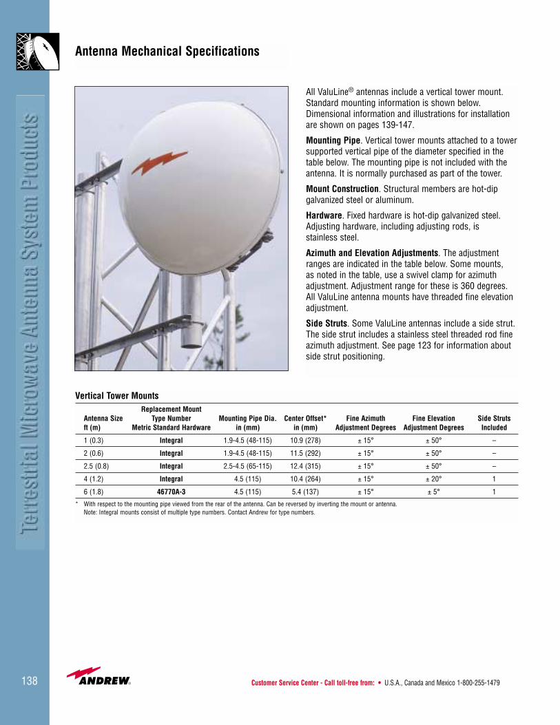
Customer Service Center - Call toll-free from: • U.S.A., Canada and Mexico 1-800-255-1479138
Antenna Mechanical Specifications
Vertical Tower MountsReplacement Mount
Antenna Size Type Number Mounting Pipe Dia. Center Offset* Fine Azimuth Fine Elevation Side Strutsft (m) Metric Standard Hardware in (mm) in (mm) Adjustment Degrees Adjustment Degrees Included
1 (0.3) Integral 1.9-4.5 (48-115) 10.9 (278) ± 15° ± 50° –
2 (0.6) Integral 1.9-4.5 (48-115) 11.5 (292) ± 15° ± 50° –
2.5 (0.8) Integral 2.5-4.5 (65-115) 12.4 (315) ± 15° ± 50° –
4 (1.2) Integral 4.5 (115) 10.4 (264) ± 15° ± 20° 1
6 (1.8) 46770A-3 4.5 (115) 5.4 (137) ± 15° ± 5° 1
* With respect to the mounting pipe viewed from the rear of the antenna. Can be reversed by inverting the mount or antenna.Note: Integral mounts consist of multiple type numbers. Contact Andrew for type numbers.
All ValuLine® antennas include a vertical tower mount.Standard mounting information is shown below.Dimensional information and illustrations for installationare shown on pages 139-147.
Mounting Pipe. Vertical tower mounts attached to a towersupported vertical pipe of the diameter specified in thetable below. The mounting pipe is not included with theantenna. It is normally purchased as part of the tower.
Mount Construction. Structural members are hot-dip galvanized steel or aluminum.
Hardware. Fixed hardware is hot-dip galvanized steel.Adjusting hardware, including adjusting rods, is stainless steel.
Azimuth and Elevation Adjustments. The adjustmentranges are indicated in the table below. Some mounts, as noted in the table, use a swivel clamp for azimuthadjustment. Adjustment range for these is 360 degrees.All ValuLine antenna mounts have threaded fine elevationadjustment.
Side Struts. Some ValuLine antennas include a side strut.The side strut includes a stainless steel threaded rod fineazimuth adjustment. See page 123 for information aboutside strut positioning.

• U.K. 0800-250055 • Australia 1800-803 219 • New Zealand 0800-441-747 Visit us at: www.andrew.com 139
Dimensions in Inches (mm)Antenna Size, ft (m) A B C D E F
1 (0.3) 15.6 (398) 15.5 (393) 10.9 (278) 4.3 (110) 8.7 (220) 1.65 (42)
All dimensions based on 4.5 in (115 mm) pipe.
1-ft ValuLine® Antenna Dimensions
A
B
C
E
D
F

Customer Service Center - Call toll-free from: • U.S.A., Canada and Mexico 1-800-255-1479140
Dimensions in Inches (mm)Antenna Size, ft (m) A B* C D E F
1 (0.3) 15.6 (398) 11.4 (289) 10.9 (278) 4.3 (110) 8.7 (220) 1.65 (42)
* 12.4 (314 mm) for VHLP1-220 antennaAll dimensions based on 4.5 in (115 mm) pipe
1-ft ValuLine® Low Profile Antenna Dimensions
D
E
Suitable for mountingto 2.0 in to 4.5 in
(50 mm - 115 mm) pipe
F
B
C
A

• U.K. 0800-250055 • Australia 1800-803 219 • New Zealand 0800-441-747 Visit us at: www.andrew.com 141
Dimensions in Inches (mm)Antenna Size, ft (m) A B C D E F
2.0 (0.6) Shielded 25.6 (651) 27.5 (699) 11.5 (292) 4.3 (110) 8.7 (220) 1.65 (42)2.0 (0.6) Standard 25.0 (637) 10.5 (266) 11.5 (292) 4.3 (110) 8.7 (220) 1.65 (42)
All dimensions based on 4.5 in (115 mm) pipe.
2-ft ValuLine® Shielded and Standard Antenna Dimensions
Suitable for mountingto 2.5 in to 4.5 in
(65 mm - 115 mm) pipe
C
B
F
A
ED
B
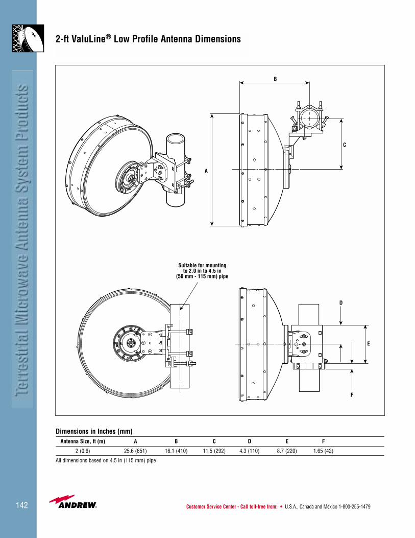
Customer Service Center - Call toll-free from: • U.S.A., Canada and Mexico 1-800-255-1479142
Dimensions in Inches (mm)Antenna Size, ft (m) A B C D E F
2 (0.6) 25.6 (651) 16.1 (410) 11.5 (292) 4.3 (110) 8.7 (220) 1.65 (42)
All dimensions based on 4.5 in (115 mm) pipe
2-ft ValuLine® Low Profile Antenna Dimensions
Suitable for mountingto 2.0 in to 4.5 in
(50 mm - 115 mm) pipe
D
E
F
C
B
A
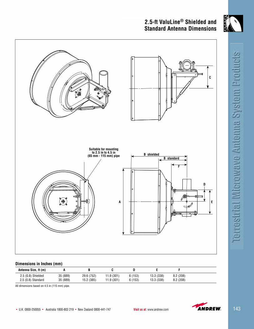
• U.K. 0800-250055 • Australia 1800-803 219 • New Zealand 0800-441-747 Visit us at: www.andrew.com 143
Dimensions in Inches (mm)Antenna Size, ft (m) A B C D E F
2.5 (0.8) Shielded 35 (889) 29.6 (752) 11.9 (301) 6 (153) 13.3 (338) 8.2 (208)2.5 (0.8) Standard 35 (889) 15.2 (385) 11.9 (301) 6 (153) 13.3 (338) 8.2 (208)
All dimensions based on 4.5 in (115 mm) pipe.
2.5-ft ValuLine® Shielded and Standard Antenna Dimensions
C
A
B
F
Suitable for mountingto 2.5 in to 4.5 in
(65 mm - 115 mm) pipeB
E
D
shieldedstandard
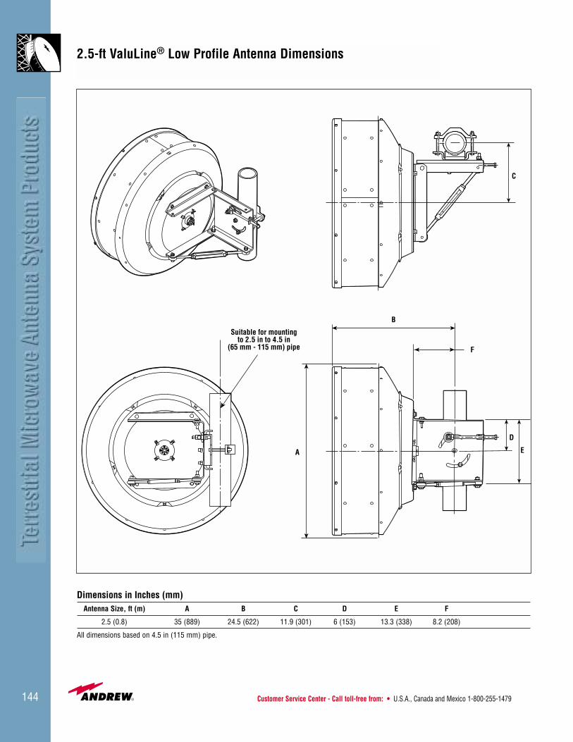
Customer Service Center - Call toll-free from: • U.S.A., Canada and Mexico 1-800-255-1479144
Dimensions in Inches (mm)Antenna Size, ft (m) A B C D E F
2.5 (0.8) 35 (889) 24.5 (622) 11.9 (301) 6 (153) 13.3 (338) 8.2 (208)
All dimensions based on 4.5 in (115 mm) pipe.
2.5-ft ValuLine® Low Profile Antenna Dimensions
C
A
B
F
Suitable for mountingto 2.5 in to 4.5 in
(65 mm - 115 mm) pipe
E
D

• U.K. 0800-250055 • Australia 1800-803 219 • New Zealand 0800-441-747 Visit us at: www.andrew.com 145
Dimensions in Inches (mm)Antenna Size, ft (m) A B C D E F* G*
4 (1.2) 16.2 (411) 11.6 (295) 14.2 (361) 10.4 (264) 21.4 (544) 30.0 (762) 21.3 (541)
H J K L
20.8 (528) 11.1 (288) 6.5 (165) 49.1 (1247)
* Applicable only for VHP Series (shielded) antennas.
4-ft ValuLine® Antenna Dimensions
C
B
A
D
L
G
F
H
J
K
E
25°+–
Suitable for mounting to 4.5 in (115 mm) pipe only.

Customer Service Center - Call toll-free from: • U.S.A., Canada and Mexico 1-800-255-1479146
Dimensions in Inches (mm)Antenna Size, ft (m) A B C D E F G
4 (1.2) 16.2 (411) 11.6 (295) 14.2 (361) 10.4 (264) 21.4 (544) 23.4 (594) 14.7 (373)
H J K L
20.8 (528) 11.1 (288) 6.5 (165) 49.1 (1247)
25°+–
ØL
G
F
H
J
K
E
C
B
A
D
Suitable for mounting to4.5 in (115 mm) pipe
4-ft ValuLine® Low Profile Antenna Dimensions
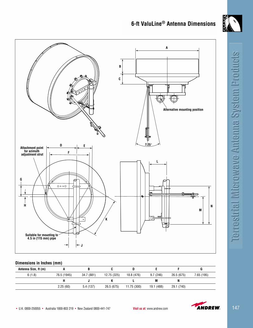
• U.K. 0800-250055 • Australia 1800-803 219 • New Zealand 0800-441-747 Visit us at: www.andrew.com 147
Dimensions in Inches (mm)Antenna Size, ft (m) A B C D E F G
6 (1.8) 76.5 (1945) 34.7 (881) 12.75 (325) 18.8 (476) 9.7 (246) 26.5 (675) 7.65 (195)
H J K L M N
2.25 (60) 5.4 (137) 26.5 (675) 11.75 (300) 19.1 (488) 29.1 (740)
6-ft ValuLine® Antenna Dimensions
25°+–
Suitable for mounting to4.5 in (115 mm) pipe
B
C
A
L
MN
J
K
F
D
G
H
E
Alternative mounting position
Attachment point for azimuth
adjustment strut
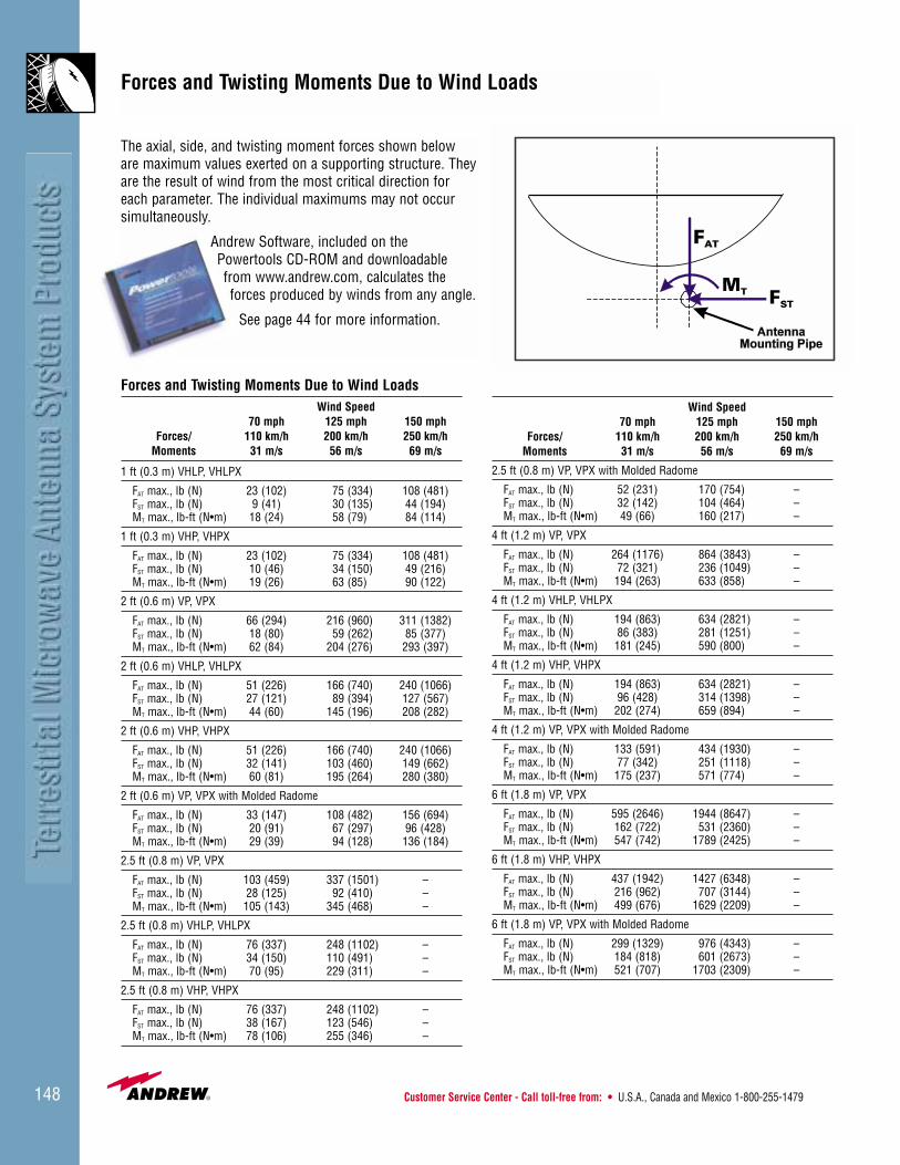
Customer Service Center - Call toll-free from: • U.S.A., Canada and Mexico 1-800-255-1479148
The axial, side, and twisting moment forces shown beloware maximum values exerted on a supporting structure. Theyare the result of wind from the most critical direction foreach parameter. The individual maximums may not occursimultaneously.
Andrew Software, included on thePowertools CD-ROM and downloadablefrom www.andrew.com, calculates theforces produced by winds from any angle.
See page 44 for more information.
Forces and Twisting Moments Due to Wind LoadsWind Speed
70 mph 125 mph 150 mphForces/ 110 km/h 200 km/h 250 km/h
Moments 31 m/s 56 m/s 69 m/s
1 ft (0.3 m) VHLP, VHLPX
FAT max., lb (N) 23 (102) 75 (334) 108 (481)FST max., lb (N) 9 (41) 30 (135) 44 (194)MT max., lb-ft (N•m) 18 (24) 58 (79) 84 (114)
1 ft (0.3 m) VHP, VHPX
FAT max., lb (N) 23 (102) 75 (334) 108 (481)FST max., lb (N) 10 (46) 34 (150) 49 (216)MT max., lb-ft (N•m) 19 (26) 63 (85) 90 (122)
2 ft (0.6 m) VP, VPX
FAT max., lb (N) 66 (294) 216 (960) 311 (1382)FST max., lb (N) 18 (80) 59 (262) 85 (377)MT max., lb-ft (N•m) 62 (84) 204 (276) 293 (397)
2 ft (0.6 m) VHLP, VHLPX
FAT max., lb (N) 51 (226) 166 (740) 240 (1066)FST max., lb (N) 27 (121) 89 (394) 127 (567)MT max., lb-ft (N•m) 44 (60) 145 (196) 208 (282)
2 ft (0.6 m) VHP, VHPX
FAT max., lb (N) 51 (226) 166 (740) 240 (1066)FST max., lb (N) 32 (141) 103 (460) 149 (662)MT max., lb-ft (N•m) 60 (81) 195 (264) 280 (380)
2 ft (0.6 m) VP, VPX with Molded Radome
FAT max., lb (N) 33 (147) 108 (482) 156 (694)FST max., lb (N) 20 (91) 67 (297) 96 (428)MT max., lb-ft (N•m) 29 (39) 94 (128) 136 (184)
2.5 ft (0.8 m) VP, VPX
FAT max., lb (N) 103 (459) 337 (1501) –FST max., lb (N) 28 (125) 92 (410) –MT max., lb-ft (N•m) 105 (143) 345 (468) –
2.5 ft (0.8 m) VHLP, VHLPX
FAT max., lb (N) 76 (337) 248 (1102) –FST max., lb (N) 34 (150) 110 (491) –MT max., lb-ft (N•m) 70 (95) 229 (311) –
2.5 ft (0.8 m) VHP, VHPX
FAT max., lb (N) 76 (337) 248 (1102) –FST max., lb (N) 38 (167) 123 (546) –MT max., lb-ft (N•m) 78 (106) 255 (346) –
Forces and Twisting Moments Due to Wind Loads
Wind Speed70 mph 125 mph 150 mph
Forces/ 110 km/h 200 km/h 250 km/hMoments 31 m/s 56 m/s 69 m/s
2.5 ft (0.8 m) VP, VPX with Molded Radome
FAT max., lb (N) 52 (231) 170 (754) –FST max., lb (N) 32 (142) 104 (464) –MT max., lb-ft (N•m) 49 (66) 160 (217) –
4 ft (1.2 m) VP, VPX
FAT max., lb (N) 264 (1176) 864 (3843) –FST max., lb (N) 72 (321) 236 (1049) –MT max., lb-ft (N•m) 194 (263) 633 (858) –
4 ft (1.2 m) VHLP, VHLPX
FAT max., lb (N) 194 (863) 634 (2821) –FST max., lb (N) 86 (383) 281 (1251) –MT max., lb-ft (N•m) 181 (245) 590 (800) –
4 ft (1.2 m) VHP, VHPX
FAT max., lb (N) 194 (863) 634 (2821) –FST max., lb (N) 96 (428) 314 (1398) –MT max., lb-ft (N•m) 202 (274) 659 (894) –
4 ft (1.2 m) VP, VPX with Molded Radome
FAT max., lb (N) 133 (591) 434 (1930) –FST max., lb (N) 77 (342) 251 (1118) –MT max., lb-ft (N•m) 175 (237) 571 (774) –
6 ft (1.8 m) VP, VPX
FAT max., lb (N) 595 (2646) 1944 (8647) –FST max., lb (N) 162 (722) 531 (2360) –MT max., lb-ft (N•m) 547 (742) 1789 (2425) –
6 ft (1.8 m) VHP, VHPX
FAT max., lb (N) 437 (1942) 1427 (6348) –FST max., lb (N) 216 (962) 707 (3144) –MT max., lb-ft (N•m) 499 (676) 1629 (2209) –
6 ft (1.8 m) VP, VPX with Molded Radome
FAT max., lb (N) 299 (1329) 976 (4343) –FST max., lb (N) 184 (818) 601 (2673) –MT max., lb-ft (N•m) 521 (707) 1703 (2309) –

• U.K. 0800-250055 • Australia 1800-803 219 • New Zealand 0800-441-747 Visit us at: www.andrew.com 149
1 ft (0.3 m), 2 ft (0.6 m), and 2.5 ft (0.8 m) ValuLineantennas are shipped as standard in totally recyclablecardboard packaging. 4 ft (1.2 m) and 6 ft (1.8 m) antennas are supplied in wire-bound crates. For shipment to more remote areas of the world, heavy duty packing is available.
Contact Andrew for details.
ValuLine® Packing
Standard VHP4 Packing
Standard VHP1 and VHP2 PackingPre-Assembled VHP4 Packing