tensile test section for monocure 3d
TRANSCRIPT

Tensile Test Section for Monocure 3D
Tensile Graphs located at the end
1 Material Testing
As Flex100 is a new material on the market there is no property sheets
available. This means material testing will be undertaken to find the best
printing settings, UV exposure time and tensile testing to find Youngs modulus.
3D Printing Testing
The LCD printing process has 6 main settings which effect the print quality.
Below is a list of them explaining what they do and how they affect the print
quality:
1) Bottom Exposure Time: Is the amount of time the UV light is on and thus
curing a thin layer of resin to the printing bed (or previous layer), that is
pressed against an FEP sheet the separates the resin from touching the
UV screen. It is usually up to 10 times as long as the normal exposure
time due to needing to grip successfully to the printing bed. If it does not
have successful adhesion to the bed, then it would cause the print to fall
off and fail.
2) Bottom Layer Count: Is the number of layers that have the extended
exposure time from ‘Bottom Exposure Time’. This is normally less than 5
and helps ensure successfully bonding with the build plate.
3) Exposure Time: Is the amount of time that the rest of the required print
layers will be exposed to UV lights. It is a lot less than the ‘Bottom
Exposure Time’ as it is curing the resin to the previously cured layer. This
is made easier as the UV lights can penetrate the resin into the previous
layer assisting in strong bonds forming. Over exposure can cause
geometry inaccuracies and under exposure can cause the same but also
form weak layer adhesion.
4) Lifting Distance: Is the amount the build plate lifts in height between
each layer to allow for fresh resin to settle underneath in preparation for
the next layer. The build plate lowers down by, ‘lifting distance minus

layer height’ to allow accurate printing. If this is not the right height than
the part may not separate from the FEP sheet and cause inaccurate
printing.
5) Lifting Speed: Is the speed in which the build plate lifts to reach the
required ‘Lifting Distance’. If this is to fast it could create pully forces on
the part and FEP and pull it off the build plate, cause layer separation,
and stretch the FEP film.
6) Light Off Delay: Is the amount of time the light is off in between curing
layers. Using this you can calculate the amount of time it takes to
complete one cycle of lifting and lowering the print bed. From this it is
possible to then increase that time allowing for a pause in between
lowering back time and giving more time for the resin to settle. This
helps with thick resins which if do not settle properly before the next
layer can cause imperfections such as gaps and layer separation.
Due to the immense amount of printing options, dozens of test prints
were conducted making minor changes between each one on individual
settings. Below are the examples of some of the test prints used and the best
printing settings that was found for different ratios of Flex100 mixed with
Rapid resin.
1.1.1 Constants for testing
- 90% support base layer coverage was required to allow the flexible resin
to have successful strength to be held up on the build plate.
- A raft was used to allow for strong bondage on the build plate and
support structures.
- Same print layout and printing shapes.
- All parts 10mm in depth unless correct settings found a test at 40mm
was conducted to finalise settings.
- A = 50 x 25mm, 1.5mm wall thickness.
- B = 50 x 2mm.
- C = 50 x 3mm.
- D = 50 x 4mm.
- E = 50mm diameter 2mm wall thickness.
- F = 25mm diameter, 1mm wall thickness.

Fig 13: Parts for testing print settings (Onshape)
Fig 14: Examples of some of the test parts
1.1.2 Printing Settings
To successfully print a light off delay calculation was formulated to allow
a custom length of time where the print head would pause before lowering
back down onto the resin/FEP sheet. This is due to the thickness of the resin.
An example of the formula for calculating the light off delay is below:
A B
C D
E
F

𝐿𝑖𝑔ℎ𝑡 𝑂𝑓𝑓 𝐷𝑒𝑙𝑎𝑦 = 𝐿𝑖𝑓𝑡 𝑇𝑖𝑚𝑒 + 𝑅𝑒𝑡𝑟𝑎𝑐𝑡 𝑡𝑖𝑚𝑒 + 𝐷𝑒𝑙𝑎𝑦 𝑊𝑎𝑛𝑡𝑒𝑑
𝑇𝑖𝑚𝑒 =𝐷𝑖𝑠𝑡𝑎𝑛𝑐𝑒
𝑆𝑝𝑒𝑒𝑑
𝑇𝑖𝑚𝑒 (𝑆𝑒𝑐) = ((𝐿𝑖𝑓𝑡 𝐻𝑒𝑖𝑔ℎ𝑡
𝐿𝑖𝑓𝑡 𝑆𝑝𝑒𝑒𝑑) + (
𝐿𝑖𝑓𝑡 𝐻𝑒𝑖𝑔ℎ𝑡
𝑅𝑒𝑡𝑟𝑎𝑐𝑡 𝑆𝑝𝑒𝑒𝑑)) × 60(𝑀𝑖𝑛)
𝑇𝑖𝑚𝑒 (𝑆𝑒𝑐) = ((5
50) + (
5
90)) × 60(𝑀𝑖𝑛) = 9.3 (𝑆𝑒𝑐)
𝐿𝑖𝑔ℎ𝑡 𝑂𝑓𝑓 𝐷𝑒𝑙𝑎𝑦 = 9.3 (𝑆𝑒𝑐) + 𝐷𝑒𝑙𝑎𝑦 𝑊𝑎𝑛𝑡𝑒𝑑 = 9.3 + 2 = 11.3 (𝑆𝑒𝑐)
11.3 = 11.5 (𝑆𝑒𝑐, 𝑅𝑜𝑢𝑛𝑑𝑒𝑑 𝑡𝑜 𝑛𝑒𝑎𝑟𝑒𝑠𝑡 0.5)
Equation 5: Light off delay for LCD printing
The larger the percentage of Flex100 the longer the ‘Delay Wanted’ had
to be. For 100% Flex100 the minimum delay needed to allow the resin to settle
properly was 2 seconds, for 90% and 70% it was 1.5 seconds, for 50% and 25%
it was 1 second, and for 0% it was left at 1 second but was not actually needed.
Below are the settings that were found to be most suitable to achieve
successful printing with such a flex resin and mixing it with a rigid resin:
Flex100 = 100% : Rapid = 0%
Fig 15: 100% Flex100 settings

Flex100 90% : Rapid 10% and Flex100 70% : Rapid 30%
Fig 16: 90% & 70% Flex100 settings
Flex100 50% : Rapid 50% and Flex100 25% : Rapid 75%
Fig 17: 50% & 25% Flex100 settings
Flex100 0% : Rapid 100%
Fig 18: 0% Flex100 settings

UV Exposure Testing
As the resin is cured by UV light, over exposure in direct sunlight will
cause parts to continue to cure. This can lead to parts discolouring developing
a yellow tinge and more brittle/rigid parts. The rigidity increase in the flexible
resin causes splitting/layer separation when the shape is deformed. The timed
over exposure testing led to a result of about 7 days behind a glass window
with about 7 hours of sun exposure each day, totalling 49 hours. This is
deemed to be acceptable as the end use is for deep sea applications where UV
over exposure would not occur.
Tensile Testing
As this material is new to the market tensile testing was done to find out
some of the main characteristics of different ratios of the material such as,
elongation at break, ultimate tensile strength (UTS), and Young’s Modulus.
Testing is done in accordance with the requirements of ‘ASTM D638 – 10
Standard Test Method for Tensile Properties of Plastics1’. It states that “Type IV
specimen shall be used for testing nonrigid plastics with a thickness of 4 mm”
(D638).
1.3.1 Tensile Testing Standards/Preparation
- The dimensions for the test pieces are as follows:
Fig 19: ASTM D638 – 10 test dimensions (D638)

Conditions for tensile testing:
- All parts printed in the same orientation. (3 orientations were tested –
face flat, edge printing, and 45-degree angle).
- All parts post cured with 405nm wavelength UV light for 10 minutes
each side, totalling 20 minutes.
- All parts kept in shaded containers until testing time, so the post UV is
maintained constant.
- 5 parts of each ratio were printed in case of defects, with the best 3
selected for testing.
- A test speed of 50mm/min as recommended in ASTM D638 – 10.
Fig 20: Designed drawing dimensions for testing (Onshape)
Fig 21: Printing orientation, On Edge, 45 Degree, and Face Flat (Chitubox)

Fig 22: Orientation testing
Fig 23: 405nm UV curing chamber
Fig 24: All prepared test pieces
45-Degree
On Edge
Face Flat Chosen
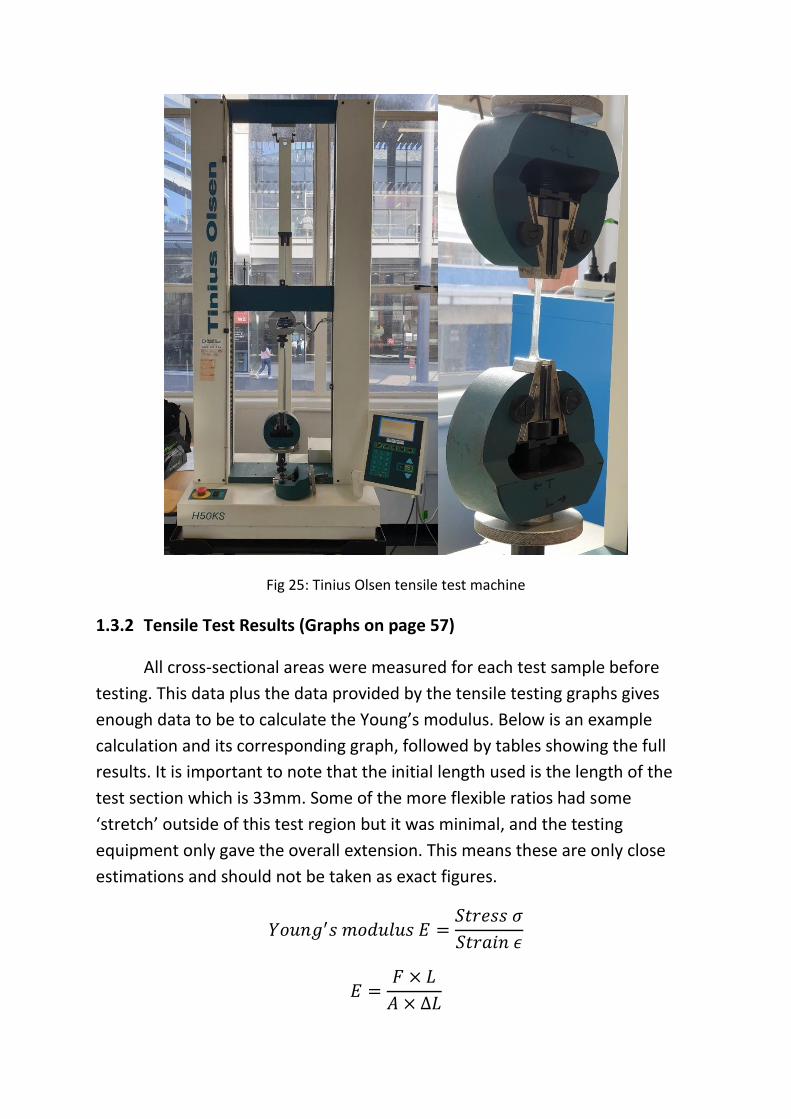
Fig 25: Tinius Olsen tensile test machine
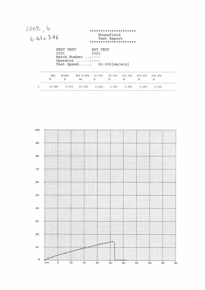
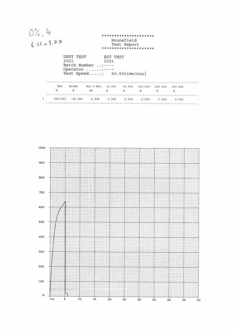
1.3.2 Tensile Test Results (Graphs on page 57)
All cross-sectional areas were measured for each test sample before
testing. This data plus the data provided by the tensile testing graphs gives
enough data to be to calculate the Young’s modulus. Below is an example
calculation and its corresponding graph, followed by tables showing the full
results. It is important to note that the initial length used is the length of the
test section which is 33mm. Some of the more flexible ratios had some
‘stretch’ outside of this test region but it was minimal, and the testing
equipment only gave the overall extension. This means these are only close
estimations and should not be taken as exact figures.
𝑌𝑜𝑢𝑛𝑔′𝑠 𝑚𝑜𝑑𝑢𝑙𝑢𝑠 𝐸 =𝑆𝑡𝑟𝑒𝑠𝑠 𝜎
𝑆𝑡𝑟𝑎𝑖𝑛 𝜖
𝐸 =𝐹 × 𝐿
𝐴 × ∆𝐿

𝐸 =530.666𝑁 × 0.033𝑚
(0.0064𝑚 × 0.00379𝑚) × (11.47 × 10⁻⁶𝑚)= 62.94 𝑀𝑃𝑎
Equation 6: Young’s modulus
Fig 26: Tinius Olsen tensile graph print out 25% No.1

Flex100 % Sample No. Width (mm) Thick (mm) Area (mm2) Length (mm) ∆Length (mm) UTS (N)
100% 4 6.41 3.96 25.38 33.00 31.22 14.67
3 6.51 3.78 24.61 33.00 38.56 20.00
2 6.52 3.88 25.30 33.00 32.63 18.33
90% 3 6.49 3.79 24.60 33.00 15.83 28.00
2 6.19 3.73 23.09 33.00 15.27 27.67
1 6.20 3.80 23.56 33.00 14.73 25.67
70% 3 6.34 3.89 24.66 33.00 13.75 63.67
2 6.37 3.81 24.27 33.00 17.62 83.00
1 6.19 3.84 23.77 33.00 16.17 80.00
50% 5 6.57 3.90 25.62 33.00 14.12 163.33
3 6.36 3.82 24.30 33.00 17.44 196.67
1 6.38 3.78 24.12 33.00 19.71 207.00
25% 3 6.49 3.77 24.47 33.00 10.23 513.33
2 6.39 3.79 24.22 33.00 10.26 493.33
1 6.40 3.79 24.26 33.00 11.47 530.67
0% 5 6.37 3.76 23.95 33.00 5.19 552.67
4 6.51 3.77 24.54 33.00 5.91 640.00
3 6.39 3.68 23.52 33.00 4.50 504.33
Table 1: Flex100 tensile test data
Young's Modulus (N/mm2) Young's Modulus (N/m2)
0.61 610794.55
0.70 695523.16
0.73 733023.06
2.37 2372751.65
2.59 2589195.93
2.44 2440751.59
6.20 6197354.03
6.41 6405401.67
6.87 6867386.13
14.90 14895726.69
15.32 15321482.67
14.37 14373127.90
67.67 67665383.18
65.49 65493378.71
62.94 62943748.23
146.77 146774105.68
145.71 145706233.71
157.38 157383703.85
Table 2: Flex100 % ratio Young’s modulus

Flex100 % Avg UTS (N) Avg Young's Modulus (MPa)
100% 17.67 0.68
90% 27.11 2.47
70% 75.56 6.49
50% 189.00 14.86
25% 512.44 65.37
0% 565.67 149.95
Table 3: Flex100 average UTS and Young’s modulus
Material Conclusion
From this we can conclude that Flex100 has some very promising
properties with 100% Flex100 stretching up to 38mm in the tensile test,
however applying the properties in a functional way is difficult. It all comes
down to the geometry of the shape guiding which ratio of resin to use. The
more flexible the part the harder it is to print larger shapes with high levels of
detail, especially those with detail where support would be required. This is
due to the high level of support needed to keep the part stable during printing
as the stress of separating from the FEP sheet can deform or cause the part to
fail if adequate support is not available. Accuracy of print is also a factor as the
flexible properties cause geometry inaccuracies during printing. The more Rigid
resin that is added the more accurate the printing becomes. The rigid resin has
very high stress potential applications, reaching a Young’s modulus of 149.95
MPa at 0% Flex100 (or 100% Rigid), compared to the 100% Flex100 of 0.68
MPa. It would make it a very good choice for any mechanical moving parts
that would be undergoing excessive strain or stress.

2 Tensile Test Graphs