tensile fracture characterization of braze joined … · tensile fracture characterization of braze...
TRANSCRIPT

GA–A22213
TENSILE FRACTURE CHARACTERIZATIONOF BRAZE JOINED COPPER-TO-CFC
COUPON ASSEMBLIES
byP.W. TRESTER, P.G. VALENTINE, W.R. JOHNSON,
E. CHIN, E.E. REIS, and A.P. COLLERAINE
FEBRUARY 1996

GA–A22213
TENSILE FRACTURE CHARACTERIZATIONOF BRAZE JOINED COPPER-TO-CFC
COUPON ASSEMBLIES
byP.W. TRESTER, P.G. VALENTINE, W.R. JOHNSON,
E. CHIN, E.E. REIS, and A.P. COLLERAINE
This is a preprint of a paper to be presented at SeventhInternational Conference on Fusion Reactor Materials,September 25–29, 1995, Obninsk, Russia, and to bepublished in the Proceedings.
Work supported bythe U.S. Department of Energy
under Contract No. DE-AC02-76CHO3073,Princeton Plasma Physics Laboratory TPX Subcontract S-03765-K
GA PROJECT 3998FEBRUARY1996

TENSILE FRACTURE CHARACTERIZATION OF BRAZE JOINEDP.W. Trestor, et al. COPPER-TO-CFC COUPON ASSEMBLIES
GENERAL ATOMICS REPORT GA–A22213 iii
Tensile fracture characterizationof braze joined copper-to-CFC coupon assemblies
P.W. Trester, P.G. Valentine, W.R. Johnson, E. Chin, E.E. Reis, and A.P. Colleraine
Telephone: (619) 455-2914; Facsimile: (619) 455-4268; e-mail: [email protected]
General Atomics, P.O. Box 85608, San Diego, California 92186-9784
Abstract
A vacuum brazing process was used to join a broad spectrum of carbon-fiber reinforced
carbon matrix composite (CFC) materials, machined into cylindrical coupons, between
coupons of oxygen-free copper (OF Cu); the braze alloy was a copper-base alloy which
contained only low activation elements (Al, Si, and Ti) relative to a titanium baseline
specification. This demonstration was of particular importance for plasma facing
components (PFCs) under design for use in the Tokamak Physics Experiment (TPX); the
braze investigation was conducted by General Atomics (GA) for the Princeton Plasma
Physics Laboratory. A tensile test of each brazed assembly was conducted. The results from
the braze processing, testing, and fracture characterization studies of this reporting support
the use of CFC's of varied fiber architecture and matrix processing in PFC designs for TPX.
Further, the copper braze alloy investigated is now considered to be a viable candidate for a
low-activation bond design. The prediction of plasma disruption-induced loads on the PFCs
in TPX requires that joint strength between CFC tiles and their copper substrate be
considered in design analysis and CFC selection.

TENSILE FRACTURE CHARACTERIZATION OF BRAZE JOINEDP.W. Trestor, et al. COPPER-TO-CFC COUPON ASSEMBLIES
GENERAL ATOMICS REPORT GA–A22213 1
I. Introduction
Approximately one-half of the carbon-fiber reinforced carbon (CFC) material specified
for the plasma facing components (PFCs) of the Tokamak Physics Experiment (TPX) will
require direct bonding to copper substrates. All the PFCs, of bolted or bonded designs, will
require active cooling. The TPX tokamak will have long pulse capability (≥1000 s) and must
accommodate high heat loads (up to 7.5 MWm–2 in strike zones of the divertor). In most
PFC zones where high heat flux (HHF) of ≥ 0.5 MWm–2 is predicted, CFC tile bonding to
copper is specified.
The primary goal of the TPX is to develop the scientific basis for a compact and
continuously-operating tokamak fusion reactor [1]. The selection basis of CFC materials for
the PFCs is addressed in a companion article [2]. As part of the early research and
development tasks supporting the design of the PFCs, GA identified the need to bond a
variety of CFC designs to copper with the use of a vacuum brazing approach. Particular
consideration is necessary for maintaining joint adherence despite the vastly different thermal
expansion coefficients of CFC (typically, <1 x 10⁻⁶ m/m/˚C) compared to copper and copper
braze alloys (~17 x 10–6 m/m/˚C). The technology of brazed CFC tiles and evaluation in
HHF tests by electron or ion beam heating is documented [3–9] and the joints were fabricated
primarily with silver-copper braze alloys containing a few percent of titanium. During
brazing, the mechanism of titanium carbide formation at the braze interface with the carbon
is effective for strong adherence. For achieving a design criterion of low neutron activation
in the PFC materials for TPX, a braze composition of mainly copper with alloying elements
comparable or lower in contribution to the generation of long-lived gamma radiation
compared to copper was of interest. Incorporating titanium as an alloying element was also
important. A commercial braze alloy of composition 93Cu-2Al-3Si-2.3Ti (wt %) was
therefore selected as a candidate braze material for bonding demonstration; the alloy is from
the class of "active" braze alloy design, which incorporates titanium as a carbide-forming
element and thereby enables metallurgical bonding to the CFC surface. Braze alloy wetting
of the carbon and maintaining adherence following the braze cooldown were considered as
the most important criteria. Adherence can be investigated quantitatively with tensile loading
of brazed joints. Correlation with elastic-plastic stress analysis offers a further opportunity to
assess the joined materials. This assessment approach was followed in the effort to provide a
demonstration of concept and processing feasibility.

TENSILE FRACTURE CHARACTERIZATION OF BRAZE JOINEDCOPPER-TO-CFC COUPON ASSEMBLIES P.W. Trestor, et al.
2 GENERAL ATOMICS REPORT GA–A22213

TENSILE FRACTURE CHARACTERIZATION OF BRAZE JOINEDP.W. Trestor, et al. COPPER-TO-CFC COUPON ASSEMBLIES
GENERAL ATOMICS REPORT GA–A22213 3
2. Experimental Approach and Procedures
2.1. Materials
Ten CFC materials were obtained for braze evaluation; their composite designs
represented a broad spectrum of constituent type and processing and included: different fiber
types (pitch, PAN); fiber architectures 1-D, 3-D, 4-D; and different matrix types (pitch, CVI).
The CFC test coupons were machined with a specified fiber axis oriented perpendicular to
the end plane (to be brazed).
Cylindrical coupons of 19 mm diameter and nominal length of 20 mm were machined
from the 3-D and 4-D CFCs. The z-axis fibers direction was oriented parallel to the cylinder
axis (tensile test axis). In addition, for selected CFCs, other orthogonal directions of
composite architecture were oriented parallel to the tensile test axis. For the 1-D CFCs,
which exhibit extreme fragility in the X-Y plane, rectangular segments of 10 mm nominal
thickness were used as the coupons; the 1-D fiber direction was oriented parallel to the
tensile axis.
Cylindrical coupons, of 19 mm diameter and nominal length of 37 mm, were machined
from oxygen-free copper, type UNS-C10100 (99.99% Cu) wrought plate. A 6.4 mm
diameter hole was machined transverse to the tensile axis direction to enable the pin-to-clevis
approach for load application.
The braze alloy used was of the tradename Copper ABA, in foil product form, produced
by GTE Wesgo Co., California, USA, of composition 93Cu-2Al-3Si-2.3Ti (wt %). The alloy
has a solidus temperature of 958˚C and a liquidius of 1024˚C. For each brazed assembly, one
braze zone was achieved with a 0.1 mm thick foil. To provide a contrast, two foils, i.e.,
0.2 mm thickness, were used at the opposite end of the CFC coupon. Foil diameters of
22 mm were used. The foils were cleaned ultrasonically in organic solvents before and after
abrading the surfaces (≤3 µm removal) on a SiC particle (15 µm diameter) abrasive grinding
paper. Prepared foil disks were stored under vacuum until ≤2 h prior to use. The end
surfaces of both the copper and CFC coupons were ground on a SiC particle (23 µm
diameter, nominal) abrasive paper to remove marks from the machining operation. Surface
contamination was removed by ultrasonic cleaning in organic solvents. Prior to brazing, the
TENSILE FRACTURE CHARACTERIZATION OF BRAZE JOINEDCOPPER-TO-CFC COUPON ASSEMBLIES P.W. Trestor, et al.
4 GENERAL ATOMICS REPORT GA–A22213
CFC coupons were exposed to a 1000˚C thermal cycle in vacuum to outgas impurities (≤ 5 x
10–3 Pa).
2.2. Braze processing
The assembly of a tensile specimen was accomplished by vertically stacking each CFC
coupon between two copper coupons and positioning the braze foil(s) at the interface regions.
An additional weight was rested (on axis) on top to achieve an applied normal stress of
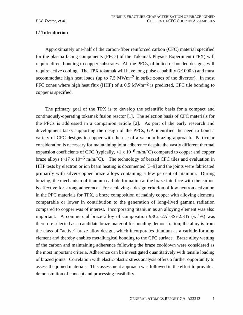
~6 x10⁻³ MPa at the braze zones. The braze thermal cycle selected incorporated a heating
rate of 450˚C/h and 0.1 h holds at both 700˚C and 980˚C to enable temperature equilibration,
and a braze hold at a 1030˚C ± 2˚ maximum (Fig. 1) in a vacuum of ≤2 x 10⁻³ Pa, followed
by a rapid cool to 900˚C and a controlled, relatively slow cool of 180˚C h–1 below 900˚C.
°C
1030°
1010°
990°
970°
950°0 4 8 12 16 20 24 28
Tmax.T (Liquidus)
Time (minutes) when temperature wasabove solidus temperature
T (Solidus)
Fig. 1. Thermal profile of braze zone in upper range of thermal cycle for the joiningof a CFC surface to copper; braze alloy Copper ABA (Cu-2Al-3Si-2.3Ti, wt%).
2.3. Characterization methods
Brazed specimens were examined on peripheral surfaces at ≤16x magnification using an
optical stereomicroscope to verify wetting of the braze at the Cu to CFC interface. Also, the
CFC coupon periphery was examined for evidence of cracking across fiber bundles and for
macrocracks larger than the inherent microcracks from CFC processing which typically are
present along the fiber bundle-to-matrix interface and within matrix regions.

TENSILE FRACTURE CHARACTERIZATION OF BRAZE JOINEDP.W. Trestor, et al. COPPER-TO-CFC COUPON ASSEMBLIES
GENERAL ATOMICS REPORT GA–A22213 5
To assess braze adherence and to achieve a measure of joint strength, a tensile test to
fracture was conducted with each specimen assembly. Load application was uniaxial,
perpendicular to the plane of the brazed joints. All tests were conducted in an (MTS
Company) electro-servo hydraulic controlled testing machine. The linkage of the load train
included the use of a universal joint and multiple pin-to-clevis pivot joints to facilitate
specimen installation and to minimize bending of the specimen. All tests were conducted at
an axial displacement rate of 2.1 x 10⁻³ mm/s. The test temperature was 21˚C. Using an
X-Y recorder, a graph of load applied versus displacement during testing was monitored.
The nominal cross sectional area of each CFC coupon was used with the failure load to
determine the fracture strength. The location of fracture was recorded with reference to the
nearest braze zone. Microscopy was employed to examine fracture surfaces and cross
sections of a few specimens.
2.4. Stress analysis
A 2-D stress analysis was conducted for three tensile specimens to determine if the
analytical results showed qualitative agreement with the strength measurements. The analysis
used the ANSYS 5.1 finite element analysis and allowed for elastic-plastic behavior of the
copper coupons during the braze cooldown event. The carbon composites were treated as an
elastic material since behavior after localized cracking during a braze cycle cooldown is an
unknown. The braze cycle was modeled as a stress-free condition at 750˚C with complete
bonding between the C-C and copper. Slow cooling was assumed to 20˚C. After this, tensile
load was applied to the copper. A yield strength of 34 MPa was used in the analysis for
annealed copper.
3. Results and Discussion
3.1. Brazed assemblies
All of the CFCs brazed well to the copper coupons. Good wetting was observed and
fillets developed on the peripheral surface of both the CFC and Cu. No evidence of gaps or
voids were observed at the braze interfaces. Macrocracks were not observed on the CFC
periphery. Exposed fiber bundles oriented perpendicular to the braze plane did not exhibit
microcracks. In Fig. 2, two of the brazed tensile specimens are shown. The light shaded

TENSILE FRACTURE CHARACTERIZATION OF BRAZE JOINEDCOPPER-TO-CFC COUPON ASSEMBLIES P.W. Trestor, et al.
6 GENERAL ATOMICS REPORT GA–A22213
(a) (b)
Cu
CFC
Cu
*
*
Fig. 2. Tensile specimens assembled by vacuum brazing copper coupons (19 mmdiameter) to CFC coupons. *Braze alloy: Copper ABA (Cu-2Al-3Si-2.3Ti, wt %).(a) CFC type: 3-D, 865-19-4, (Allied Signal Inc.) (b) CFC type: 4-D Fineweave(Fiber Materials Inc.).
regions on the CFC reveal the locations of these Z-axis fiber bundles. The 3-D pseudo
random fiber orientation, characteristic of the Fig. 2(a) CFC, is in contrast to the linear
bundle orientation characteristic of the fully woven type CFC in Fig. 2(b). The braze fillets
are similar for both specimens; the Copper ABA alloy did not flow beyond the fillet onto the
CFC surfaces. However, for the copper coupons, localized flow beyond the fillet was
typically observed.
Each 1-D CFC exhibited a few macrocracks through the coupon thickness, i.e., the crack
planes were parallel to the Z-axis fiber bundles; more cracks of this form and orientation
were observed after the braze cycle. This observation was not unexpected as 1-D CFCs are
typically very weak in tension when stressed parallel to the X-Y plane; indeed, fracturing of
this type was occasionally experienced during the machining and/or handling of the 1D CFC
stock.

TENSILE FRACTURE CHARACTERIZATION OF BRAZE JOINEDP.W. Trestor, et al. COPPER-TO-CFC COUPON ASSEMBLIES
GENERAL ATOMICS REPORT GA–A22213 7
3.2. Braze microstructure
In Fig. 3, a photomicrograph is presented to show the microstructure features of the
Copper ABA braze alloy after the joining of copper to the CFC type FMI 4-D C-C
Coarseweave. The braze zone appeared uniform both in thickness and microstructural
features across the examined diametral section. The joint in Fig. 3 incorporated two foils;
therefore the modest normal stress of 6 x 10⁻³ MPa during brazing compressed the initial
0.2 mm of foil thickness to a braze zone thickness of 0.08 mm. Evidence of porosity or
defects was negligible in the braze. After examining the joints in all of the ten CFC brazed
specimens, it would appear that the use of one 0.1 mm thickness foil is sufficient to obtain a
satisfactory joint. Upon examination of the CFC periphery adjacent to the braze zone, the
presence of isolated microcracks appeared limited to within matrix "islands" and along fiber
bundles oriented parallel to the braze plane. The dark gray phase within the braze zone of
Fig. 3 was analyzed (during SEM analysis) by the energy dispersion x-ray method and was
determined to be a Cu phase rich in Si and Ti, i.e., alloying elements of the specified braze
alloy. At the interface of the braze and CFC coupon a phase of high Ti content was detected
which is typical of titanium carbide phase which is formed there at the time of brazing.
Copper
Braze Zone
4D C–C(Coarseweave)
50µm
Fig. 3. Microstructure of cross-sectioned braze joint; braze alloy (Copper ABA) between coupons ofOF Copper UNS-C10100 and CFC, type FMI 4-D C-C Coarseweave composite. *Interface phase ofTiC (~5 µm thickness) formed during brazing. NOTE: Z-axis fibers are perpendicular to braze plane.

TENSILE FRACTURE CHARACTERIZATION OF BRAZE JOINEDCOPPER-TO-CFC COUPON ASSEMBLIES P.W. Trestor, et al.
8 GENERAL ATOMICS REPORT GA–A22213
3.3. Braze joint strength
The braze specimens demonstrated a linear relation of tensile load versus extension up
to the load for fracture. Except for two strong 1-D CFCs, fracture occurred within the CFC
coupons very near the braze zone, at a tensile stress lower than the 0.2% offset yield strength
(28 MPa) of the annealed OF copper. The fracture plane was typically at an angle nearly
perpendicular to the load axis, parallel to the braze plane, and between 0.1 and 0.3 mm from
the braze, as shown in the photographs of Fig. 4. No lack-of-bonding type defects were
observed on the fracture surface of the ten tested specimens. The strengths ranged between 2
and 20 MPa for the specimens incorporating the 3-D or 4-D CFCs; these values are low
compared to the reported or estimated tensile strengths of the CFCs. In Table 1, a summary
is presented of the ten 4-D, 3-D and 1-D CFCs brazed and tested. Pertinent pedigree of
processing is provided in the upper half of the table. The lower part of Table 1 lists the
fracture strength values from the tensile test of each specimen assembly of the corresponding
CFC and copper coupons brazed with the Copper ABA alloy. The footnotes clarify the
orientation of the CFC fiber architecture in relation to the braze plane and the uniaxial
direction of the tensile test. The bottom row of Table 1 identifies the location of the fracture
in relation to the nearest braze plane and more specifically to which braze zone, i.e., the zone
of one 0.1 mm thickness braze foil or two foils (0.2 mm).
3.4. Fracture surface microstructure
Scanning electron microscopy (SEM) analysis of the fracture surface of the FMI 4-D
Coarseweave CFC coupon revealed a characteristic which helps explain the mode of fracture
and relatively low strength level. In Fig. 5, the SEM micrograph presented delineates the
fiber bundle ends which were perpendicular to the braze plane. A Ti and Cu rich zone
(detected by energy-dispersion x-ray analysis) covers the bundle ends. This feature was
typical of a majority of the bundles. This observation strongly supports an explanation of
CFC strength as being a function of the fiber volume fraction of the CFC that is oriented at a
steep angle to the braze plane. The examination of a cross-section oriented perpendicular to
the braze plane (of the opposing fracture half) revealed no voids or cracks in the braze layer.
Further, the braze layer appeared adherent to the copper coupon. For two CFCs listed in
Table 1 information known about the composite strength and fiber volume enabled a
comparison of composite strength, braze joint strength and the product of fiber volume
fraction and CFC tensile strength (for a specific orientation). Table 2 presents this

TENSILE FRACTURE CHARACTERIZATION OF BRAZE JOINEDP.W. Trestor, et al. COPPER-TO-CFC COUPON ASSEMBLIES
GENERAL ATOMICS REPORT GA–A22213 9
(a) (b)
Cu
Cu
CFC
Fig. 4. Typical fracture locations in brazed specimens following tensile test tofailure, at 21˚C. (a) CFC type: 3-D, 865-19-4 (needled fibrous felt and CVImatrix); (b) CFC type: 4-D Fineweave (hexagonal fully woven and pitchmatrix).
information. The rationale for assuming fiber ends (brazed to copper) are the primary carrier
of tensile load would appear to be reasonable on a first order basis.
3.5. 1-D CFC fracture characteristics
Two of the 1-D CFC braze specimens were exceptionally strong as compared to the 3-D
and 4-D type CFCs. Loading of the specimen with the MKC-1PC CFC was stopped at
48.8 MPa and unloaded. The copper coupons had experienced appreciable plastic strain. A

TENSILE FRACTURE CHARACTERIZATION OF BRAZE JOINEDCOPPER-TO-CFC COUPON ASSEMBLIES P.W. Trestor, et al.
10 GENERAL ATOMICS REPORT GA–A22213
Fig. 5. Fracture surface microstructure of the CFC coupon. Ends of the Z-axis fiberbundles (where they were joined to the braze) are revealed by light shading by the Ti-rich copper layer of the braze-zone interface. SEM micrograph image achieved withback-scattered electrons. Fracture surface of the adjacent CFC matrix and fracturedfibers (parallel to braze plane) are not covered with braze alloy and are ≤1 mm fromthe braze zone.
cross section made perpendicular to the braze planes revealed no braze defects and no cracks
transverse to the unidirectional carbon fibers .

TENSILE FRACTURE CHARACTERIZATION OF BRAZE JOINEDP.W. Trestor, et al. COPPER-TO-CFC COUPON ASSEMBLIES
GENERAL ATOMICS REPORT GA–A22213 11
Table 2. Correlation of Brazed Joint Strength and CFC Composite Parameters
Fiber Volume Fraction forCFC CompositeOrientation(a)
(Fiber VolumeFraction) x
CFCComposite
Type(b)
CFC Producer’sEstimated TensileStrength for CFC
(MPa)
CFC AxisPerpendicularto Braze Plane Vfiber/V
Brazed Joint(Cu-to-CFC)Strength(b)
(EstimatedTensile Strength
of CFC)(MPa)
4-DFineweaveCFC (FMI)
200 Z 0.209 18.2 41.8
55 U 0.092 10.0 5.1
3-D needledfibrous felt865-19-4(AlliedSignal Inc.)
100 Z 0.065 6.7 6.5
100 X 0.098 9.0 9.8
(a)The CFC fiber volume fraction Vfiber/V is the produce of overall fiber volume of CFC multipliedby the fiber volume distribution of a specified composite orientation.
(b)CFC descriptions and fracture strength values from Table 1.
The VGCF-C CFC is different from the other two 1-D CFCs in that the fiber lengths are
typically much shorter and not continuous across the 11 mm coupon thickness. Inherent
strength of the CFC would therefore be influenced substantially by the carbon matrix.
3.6. Stress analysis
The 2-D elastic-plastic analysis predicted very high tensile residual stresses near the
specimen periphery in the CFC following cooldown from the braze temperature because of
the extremely different thermal coefficients-of-expansion (CTE) between the Cu and CFC.
However, with the 1-D CFC, the relatively high CTE and lower modulus of elasticity in the
X-Y plane directions enables residual tensile stress to remain below the reported ultimate
strength of the MKC-1PH in the 1-D, i.e., Z-direction. For the 3-D and 4-D CFCs, fracture
was predicted during cooldown from the braze temperature due to tensile stresses exceeding
the reported CFC strength values. In fact, no brazed specimens exhibited fracture after the
TENSILE FRACTURE CHARACTERIZATION OF BRAZE JOINEDCOPPER-TO-CFC COUPON ASSEMBLIES P.W. Trestor, et al.
12 GENERAL ATOMICS REPORT GA–A22213
braze cycle. Plastic straining of the annealed copper helps to relieve stresses in the CFCs.
However, the additive stored residual stress in the CFC segment of the brazed specimens may
be a factor in causing fracture during the tensile tests at stress levels substantially lower than
values reported for unbrazed CFC. In addition, microcracking within the carbon matrix
zones may aid in the relief of CTE derived residual stresses.

TENSILE FRACTURE CHARACTERIZATION OF BRAZE JOINEDP.W. Trestor, et al. COPPER-TO-CFC COUPON ASSEMBLIES
GENERAL ATOMICS REPORT GA–A22213 13
4. Conclusions
The results from these processing, testing and characterization studies support the use of
CFC composite designs, i.e., of varied fiber architecture and matrix processing, in bonded
CFC-to-copper PFC designs for TPX. To proceed further, HHF testing of CFC tiles bonded
to copper substrate is warranted to evaluate actively cooled CFC flat block and macroblock
designs. Further, the braze alloy Copper ABA (Cu-2Al-3Si-2.3Ti wt%) has been shown to be
a viable candidate for achievement of the low-activation braze designs of specific interest to
TPX. In addition to the stresses arising at a joint interface from plasma operational and
vessel bakeout cycles, plasma disruption-induced loads predicted for TPX will develop
impulsive stresses on CFC tiles and therefore require joint tensile strength levels to be
considered in PFC design and CFC selection; the reported results should be useful in
conducting these engineering tasks.

TENSILE FRACTURE CHARACTERIZATION OF BRAZE JOINEDCOPPER-TO-CFC COUPON ASSEMBLIES P.W. Trestor, et al.
14 GENERAL ATOMICS REPORT GA–A22213

TENSILE FRACTURE CHARACTERIZATION OF BRAZE JOINEDP.W. Trestor, et al. COPPER-TO-CFC COUPON ASSEMBLIES
GENERAL ATOMICS REPORT GA–A22213 15
References
[1] W.T. Reiersen and the TPX Team, in Proc. of the 15th IEEE/NPSS Symposium on
Fusion Engineering, Vol. 1, 1994, p 387.
[2] P.G. Valentine, R.E. Nygren, R.W. Burns, P.D. Rocket, A.P. Colleraine, R.J. Lederich,
and J.T. Bradley III; "High Heat Flux Testing of CFC Composites for the Tokamak
Physics Experiment;" to be presented at the 7th International Conf. on Fusion Reactor
Materials, Obninsk, Russia, September 25–29, 1995.
[3] S. Suzuki, M. Araki, K. Sato, K. Masaki, K. Nakamura, M. Akiba, T. Ando, K.
Yokoyama, M. Dairaku, Y. Ohara, in Proc. of the 18th Symposium on Fusion
Technology, 1994, p 311.
[4] H.D. Falter, D. Ciric, E.B. Deksnis, P. Massmann, K. Mellon, A.Peacock, M. Akiba,
M. Araki, K. Sato, S. Suzuki, A. Cordella, in Proc. of the 18th Symposium on Fusion
Technology, 1994, p 291.
[5] M. Onozuka, M. Toyoda, S. Tsujimura, M. Inoue, and M. Satoh, in Proc. of the 18th
Symposium on Fusion Technology, 1994, p 315.
[6] R. Mitteau, P. Chappuis, P. Deschamps, M. Febvre, J. Schlosser, H. Viallet,
G. Vieider, in Proc. of the 18th Symposium on Fusion Technology, 1994, p 435.
[7] M. Brossa, D. Ciric, E. Deksnis, H. Falter, U. Guerreschi, A. Peacock, M. Pick,
M. Rossi, Y. Shen, F. Zacchia, in Proc. of the 18th Symposium on Fusion Technology,
1994, p 375.
[8] R.E. Nygren, C.A. Walker, T.J. Lutz, F.M. Hosking, R.T. McGrath, J. Nucl. Mater.
212–215, 1994, 1621.

TENSILE FRACTURE CHARACTERIZATION OF BRAZE JOINEDCOPPER-TO-CFC COUPON ASSEMBLIES P.W. Trestor, et al.
16 GENERAL ATOMICS REPORT GA–A22213
[9] J. Linke, M. Akiba, H. Bolt, J. van der Laan, H. Nickel, E. van Osch, S. Suzuki, and
E.~Wallura, J. Nucl. Mater. 196–198, 1992, 607.

TENSILE FRACTURE CHARACTERIZATION OF BRAZE JOINEDP.W. Trestor, et al. COPPER-TO-CFC COUPON ASSEMBLIES
GENERAL ATOMICS REPORT GA–A22213 17
Acknowledgments
The authors express appreciation of efforts of the following personnel at General
Atomics: D.L. Sevier, N.D. Blatchford, R.R. Enriquez, R.O. Harrington, Jr., W.E. Simpson,
R.F. Stetson, and D.R. Wall. Thanks is extended to the CFC producers who sold or donated
composite materials and provided the CFC pedigree information for this braze evaluation
study. For the donation of the OF Copper plate stock, our appreciation is expressed to
Sequoia Brass and Copper, California, USA. This work was supported by the U.S.
Department of Energy under Contract No. DE-AC02-76CH03073, Princeton Plasma Physics
Laboratory TPX Subcontract S-03756-K.