tensile armor wires submitted to slow strain rate tests in
TRANSCRIPT

DOI: http://dx.doi.org/10.1590/1980-5373-MR-2018-0465Materials Research. 2019; 22(3): e20180465
Tensile Armor Wires Submitted to Slow Strain Rate Tests in a Corrosive Environment and Cathodic Protection: a Comparison Between Two Different Microstructures
Mariana dos Reis Tagliaria, Marcio Ribeiro Antunesa, Jhuly Gleice Nascimento dos Santosa,
Fabricio Pinheiro dos Santosb, João Marcio Castilho dos Santosb, Tiago Falcadea* , Afonso Regulya
Received: July 04, 2018; Revised: January 11, 2019; Accepted: April 10, 2019
Tensile armor in flexible pipes consists of two or more layers of steel wires. Damage to the outer sheath may cause ingress of seawater in the annular space and thus corrosion of the armor wires. This work focused on the susceptibility of these wires to stress corrosion cracking (SCC) and hydrogen embrittlement (HE) using a slow strain rate test (SSRT) under a bending load in an environment that contains chlorides. The behavior of two different microstructures was compared: martensite and pearlite plus ferrite. Furthermore, the materials were mechanically and metallurgically characterized. The results indicate that martensitic steel is more sensitive to both hydrogen embrittlement and stress corrosion cracking than pearlitic-ferritic steel.
Keywords: Tensile armor, Stress corrosion cracking, hydrogen diffusion, hydrogen embrittlement.
* e-mail: [email protected]
1. IntroductionFlexible pipelines are offshore equipment extensively
employed in oil and gas sector as oil production and gas injection pipes; the former conducting oil and hydrocarbons and the second mostly employed to enhance oil production capacity of old wells. The structure are fabricated using several metallic and nonmetallic layers and have been attracting a significant amount of attention as a successful solution for deep and shallow water risers and flowlines systems worldwide1. An image representing a flexible riser is presented in Figure 12. The riser is composed of polymeric layers that work as sealing, insulating and/or anti-wear components3,4, while the metallic layers withstand imposed and structural loads1,5-7. One of these metallic layers, the tension armor, is a structural layer with a lay angle between 20 and 55 degrees8. This layer consists of helically wound flat metallic wires that are typically counter-wound in pairs and are generally made of carbon steel 9, can completely or partially sustain the tensile loads of a pipeline1,10-13 and are the object of study in this paper.
One of the main problems associated with the integrity and performance of the metallic components in flexible risers concerns the contact between tension armor wires and seawater caused mainly by damage to the external sheath layer 14,15. In this context, if seawater enters the annular space between the outer sheath and the sealing layer and makes contact with wires from tension armor, failure caused by environmentally assisted cracking (EAC) must be considered 14,16,17. Even minimal uniform corrosion could produce a brittle fracture, resulting in rupture of the wires,
which significantly reduces the structural capacity of the pipe and leads to its premature failure 6.
The difficulty in detection of cracks before sudden failure is among the industry major concerns and, consequently, the aim of failure analysis research. Frequently, the occurrence of certain types of EAC, in special stress corrosion cracking (SCC) and hydrogen embrittlement (HE) depends on the simultaneous presence of three requirements: i. a susceptible material; ii. reactive environment; and iii. sufficient tensile stress to induce cracking 18. The interactions between these corrosion and mechanical factors are the key to understanding failure by cracking in SCC or HE phenomena.
These types of EAC are often observed in pipes and tubes, especially in the oil and gas sectors 11,19-23. However, they occur by different mechanisms. Whereas SCC is a process under the anodic regime, HE is essentially a process under the cathodic regime 18. The susceptibility of steel to these types of EAC is often related to the chemical composition; surface state - such as the surface roughness and presence of
aLaboratório de Metalurgia Física - LAMEF, Universidade Federal do Rio Grande do Sul, Porto Alegre, RS, Brasil
bPETROBRAS, Rio de Janeiro, RJ, Brasil
Figure 1. Typical cross section of a flexible pipe. Adapted from [2]

Tagliari et al.2 Materials Research
defects and stress concentrators; and mechanical resistance of the material 24-26.
There are few studies on the influence of microstructure in the EAC processes of steel. The presence of SCC in austenitic steel was reported by Rondelli et al., who demonstrated anodic control through the breakdown and repair of a passive film in sodium hydroxide 27. Nevertheless, some authors have even reported the existence of this type of failure in ferritic-pearlitic and martensitic steels. Carneiro et al. showed that polygonal ferritic-pearlitic grained microstructure steel had a crack growth rate higher than that observed in steel with a very refined microstructure28. Prawoto et al. demonstrated that the martensitic microstructure had a higher susceptibility to SCC than that of the ferritic-pearlitic one 29.
Hydrogen embrittlement depends on H adsorption coverage on the surface and the amount of hydrogen traps in the material. Previous works showed that hydrogen trapping under cold working conditions produced by cold rolling increased H absorption into steel. Consequently, this microstructural condition was found to be sensitive to hydrogen embrittlement 30. The resistance to HE is inversely correlated to the yield strength for the same steel and microstructure. However, the HE resistance and yield strength depend on the microstructure, as observed by Lu and Lou 10, who found that steel with a fine-grained bainite plus ferrite structure is better than others with a ferrite plus pearlite microstructure.
Tension armor wires in flexible risers are responsible for sustaining the load of the overall structure and for transferring the load through the end-fitting to the platform, which is important to maintain the structural integrity of the set. The ultimate tensile stress (UTS) of these wires is their main acceptance criterion once it has a direct relation to the safety coefficient of the high responsible structures 31. Therefore, to evaluate the effect of microstructure on the susceptibility to EAC, this study focused on the behavior of two carbon steel wires with similar ultimate tensile strengths and different microstructures, the last resulting from distinct fabrication routes, when exposed to an environment containing chlorides. In addition, the effect of cathodic protection was also explored.
2. Materials and Methods
2.1 Metallurgical Features
The chemical composition of two steel wires: M1 which is pearlitic-ferritic and M2 which is martensitic, were determined by optical emission spectroscopy (Model Spectrolab from Spectro). Both microstructures could be found in offshore equipment. The samples were identified as carbon steel UNS G10500; their compositions are given in Table 1. These wires mainly differ in their microstructure and hardness and, even
though the amount of certain alloying elements differ from M1 to M2, both are considered mild steels.
A conventional metallographic approach was employed for the metallurgical investigations. The samples were set with a polishing procedure using sandpapers from #120 to #1200 followed by 4- to 1-µm diamond pastes. They were etched using a 2% Nital solution to reveal the microstructure and Picral etchant for the grain size determination 32. Microstructural analysis was carried out using optical microscopy (Olympus, BX51M) for longitudinal and transversal samples taken from the wires. The level of inclusions was determined at 100X magnification according to ASTM-E45 33.
The typical structure of cold worked components was observed in the microstructure of the M1 material shown in Figure 2. These micrographs show a refined microstructure composed of pearlite and ferrite aligned with the cold drawing direction. The grain size could not be determined for this steel because of the high level of grain refinement achieved as a result of the cold work.
The microstructures from the longitudinal and transversal sections of the M2 steel are shown in Figure 3 and consist of a homogeneous tempered martensite. An ASTM No. 9.5 grain size was measured for the M2 material according to ASTM E 11234.
2.2 Electrochemical Features
Potentiodynamic polarization curves were obtained to characterize the electrochemical behavior of the studied materials. For that purpose, an electrochemical three-component cell was assembled in which the working electrode was the steel itself with platinum as the counter electrode and a saturated calomel electrode (SCE) as the reference. The tested environments simulated the flooded annulus condition of flexible pipes with an aerated aqueous solution containing 3.5% by weight dissolved NaCl at an initial pH of approximately 6 at room temperature. A linear sweep voltammetry procedure was executed after an hour of potential stabilization from 750 mV below the open circuit potential to 500 mV above it. In addition, polarization curves initiating around the open circuit potential (150 mV cathodic and anodic) were generated to calculate Ecorr and icorr.
Chronoamperometry was carried out at a potential of -1050 mV for 10 800 s to observe the behavior of each microstructure under cathodic protection. Afterwards, the samples were cleaned with acetone and stored in liquid nitrogen before thermal desorption at 400 °C for 30 minutes. This procedure allows for the amount of diffusible hydrogen in metallic materials to be obtained. All of the electrochemical and thermal desorption analyses were carried out in triplicate.
2.3 Mechanical Features
To investigate the mechanical behavior of the steel, tensile tests were performed in an electromechanical machine (Instron, 5585H) on flat subsized samples for each material according

3Tensile Armor Wires Submitted to Slow Strain Rate Tests in a Corrosive Environment and Cathodic Protection: a Comparison Between Two Different Microstructures
to ASTM E8/E8M/2013a12, and Vickers microhardness tests (Instron, Tukon 2100) were performed using a load of 0.3 kgf on the metallographic samples according to ASTM E384-11e113. The yield stresses and ultimate tensile strengths obtained, as well as the Vickers microhardness values, are summarized in Table 2. The declared value of expanded uncertainty was obtained through a t-Student distribution with a coverage probability of 95.45%. The degree of freedom for each result is shown in Table 2. The uncertainty was calculated according to the Guide for Uncertainty of Measurement (GUM)35.
2.4 Slow Strain Rate Tests (SSRT)
Rectangular wire sections with the dimensions 12 (width) x 170 (length) x 3 mm (thickness) were degreased and cleaned36 prior to the SSRT. Each test was carried out in triplicate. A scheme of the SSRT (EMIC, DL-2000) configuration in three-point bending with a 100 mm distance between the upper rollers is shown in Figure 4. This loading configuration and specimen geometry were adopted due to the difficulty in machining standardized tensile test specimens from the available wires as suggested by ASTM G12937. In addition,
Table 1. Chemical composition of materials under investigation.
Chemical Composition (% mass)
Element C Si Mn P S Cr Mo Ni
M1 0.502 0.195 0.945 0.0062 0.0040 0.0394 <0.005 0.0549
M2 0.546 0.198 0.667 0.0126 0.0127 0.0188 <0.005 <0.060
Element Al Co Cu Nb Ti V B Fe
M1 <0.001 0.031 0.0286 0.001 0.0015 0.0025 0.001 Balance
M2 <0.001 0.020 0.0100 0.001 0.0010 0.0010 0.002 Balance
Figure 2. Microstructure of M1 material; (A) longitudinal section; (B) transversal section. Nital 2% etchant.
Figure 3. Microstructure of M2 material showing tempered martensite in; (A) longitudinal section; (B) transversal section. Nital 2% etchant.
Tagliari et al.4 Materials Research
the slow bending test can be advantageous, as it enables high plastic deformation without necking, which is typical for traditional SSR tensile tests. Barsanti et al 37 found that a slow bending test at a 50-mm deflection was less severe than traditional slow strain rate tensile tests because the maximum deformation of the bending specimen was limited by ~20%. In this case, the SSR tensile tests provided more favorable conditions for hydrogen embrittlement because deformation could exceed 20% in the necking zone. The average local strain rate should be sufficiently slow to allow time for certain corrosion processes to take place, but fast enough to produce failure or cracking of the specimen 37. In this work an effective strain rate of 7.7 x 10⁻⁷s-1 was adopted 19,38,39. The test was programmed to stop when the displacement reached 30 mm.
2.5 SSRT environment and evaluation
The test solution was the same as that used in the electrochemical tests. However, solution aliquots were taken periodically at 24-h intervals to monitor the pH, and the entire solution was changed to a fresh one every time the pH dropped to 4.
To evaluate the susceptibility of steel to hydrogen embrittlement, cathodic polarization was applied using a three-electrode cell assembly, as shown in Figure 5. The working electrode was the steel specimen, along with a rare earth-coated titanium electrode and a saturated calomel electrode (SCE) as auxiliary and reference electrodes, respectively. The experiments were performed by applying a constant cathodic potential with respect to the steel sample, namely, -1050 mV vs SCE 40. The samples were prehydrogenated at the same potential for 24 hours under a pre-load of 150 N.
The effect of the aforementioned environment and loading in the SCC susceptibility of the wire samples was
evaluated during the SSR tests conducted at OCP. Furthermore, experiments in air were carried out to obtain a reference for the investigated conditions.
The degree of susceptibility to EAC was generally assessed by observing differences in the behavior of failure modes and the variations on mechanical properties between tests conducted in a specific environment (3.5% NaCl) with cathodic protection and at OCP and the tests conducted in a controlled environment (air). The qualitative parameters are expressed as the deflection when the fracture is reached or at 30 mm when no fracture was observed and as the area under the load vs deflection curve, which is proportional to the absorbed energy until fracture. Thus, the parameters used for comparing the losses of mechanical properties due to environment exposition were the deflection at fracture (D), the maximum bending force (F) and area below the curve (A).
These relative losses were evaluated in comparison to the values when the test were conducted in air using Equation (1), adapted from ASTM G129, for the deflection ratio corresponding to the maximum bending force37:
(1)
For tests carried out with cathodic polarization, the reduction in mechanical properties induced by hydrogen, i.e., the susceptibility to hydrogen embrittlement, is defined using Equation (2)37:
(2)
%XR XX1 100SCC
AIR
SOL #= -T Y
%XR XX1 100HE
AIR
H #= -T Y
Table 2. Results for mechanical properties from M1 and M2 steels, where: σe = Yield strength; UTS=Ultimate tensile strength; Ue = Expanded Uncertainty; νeff = Degree of freedom; k = coverage factor.
M1(pearlitic-ferritic) M2(martensitic)
Ue νeff k Ue νeff k
YS (MPa) 1266 19.63 4.21 2.81 1509 30.57 3.89 3.18
UTS (MPa) 1752 30.99 3.77 2.96 1760 31.89 3.81 3.18
Hardness (HV) 393 25.3 3.67 1.96 497 25.7 4.1 1.96
Figure 4. Test configuration scheme.
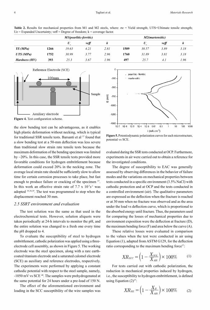
Figure 5. Potentiodynamic polarization curves for each microstructure, potential vs SCE.

5Tensile Armor Wires Submitted to Slow Strain Rate Tests in a Corrosive Environment and Cathodic Protection: a Comparison Between Two Different Microstructures
where X assumes the values of deflection (D), the maximum bending force (F) or the area under the curve (A) in the results of SSRT under each condition.
3. Results and Discussion
Figure 5 shows potentiodynamic polarization curves for the both materials. It can be noted that the anodic reactions had a higher intensity for the martensitic microstructure than for the pearlitic one. The nobler character of pearlitic can be seen through the extrapolation of the Tafel lines: even with no consistent differences in the corrosion potential, a slightly shift of the corrosion current density was observed; the martensitic structure presented an icorr of 91.0 ± 5.4 µA.cm-2, while the pearlitic structure showed an icorr of 48.5 ± 16.5 µA.cm-2. This behavior could be related to the high surface energy present in the martensite structure, leading to a lower activation barrier for the anodic reactions passing by. In addition, El-Rubaiey et al. 41 demonstrated the tendency to form pitting-like corrosion in microfilms of carbides formed in the martensitic microstructure.
On the other hand, for an applied cathodic potential of -1050 mV, the cathodic current density values for martensite reached twice as high the values for pearlitic. This behavior indicated that for the same cathodic overpotential, the hydrogen reaction was greater facilitated by that martensitic structure than by the pearlitic structure. This tendency was corroborated by the chronoamperometric results, as shown in Figure 6. Primarily, the cathodic current was slightly higher for the martensite structure, as expected after the observations of the polarization curves. The difference between the cathodic currents in martensite and in pearlite, however, started to increase after the first half hour and more significantly after reaching a steady state at 3600 s. At this time, the current developed by the martensitic structure was tenfold that observed in the pearlite structure. From the hydrogen reaction charge calculated over each curve, a value of 81.7 ± 5.35 mC.cm-2 can be seen for pearlitic, whereas for martensite, the value reached approximately 612 ± 127 mC.cm-2. These values represent the total charge of hydrogen reduced onto the steel surface 42 but do not necessarily denote the amount of hydrogen that diffuses through the material. Notwithstanding, the pearlitic structure presented 16.0 ppm of diffusible hydrogen, while the martensitic structure showed 25.2 ppm, as measured by thermal desorption, thus indicating that not only a greater amount of hydrogen is formed but also a greater amount of hydrogen diffuses into the martensitic structure.
As reported in the literature, cementite lamellae in pearlite and martensite laths act as a diffusion barrier for hydrogen diffusion. Moreover, Luu and Wu demonstrated that hydrogen solubility increased in the martensitic structure 43. In the case of the fine martensitic structure observed in the M2 material, the number of possible hydrogen barriers was greater than those present in M1 - composed of refined
pearlitic with large islands of ferrite. In addition, Depover 44 demonstrated that the higher the carbon content, the higher the total and diffusible hydrogen. These materials have a similar carbon content; however, M2 presents a slightly greater amount of carbon than M1, helping to increase its tendency to absorb hydrogen.
The load-deflection curves obtained from SSRTs for the studied conditions are shown in Figure 7. When tested in air, the highest force value and maximum deflection without fracture were achieved. Similar behavior was observed for the systems in solution without CP, showing little reduction in deflection and in maximum bending force with no fracture. The material with a cold-hardened microstructure without cathodic protection showed a low susceptibility to stress corrosion cracking; compared with the air tests, it showed a similar deflection and a maximum bending force. Visual inspection revealed corrosion products on the surface of samples. Nonetheless, SEM observations were not carried out due to the absence of a rupture.
On the other hand, the specimen tested under CP showed fracturing with a lower deflection and no significant changes in the maximum bending force compared to the air test. According to the previous work by Hwang and Shaw 30, cold work increases the amount of dislocations, which
Figure 6. Transients of cathodic current density for each microstructure.
Figure 7. SSRT curves from pearlitic-ferritic steel in three different environments (air; solution with and without CP).

Tagliari et al.6 Materials Research
in turn affects the HE because of the attraction of mobile hydrogen 45,46.
Based on the studied conditions (Table 3), the effect of the environment in environmentally assisted cracking of the pearlitic microstructure was quite small, as can be seen by the decline in the area under the curve reduction of 3.8%. In addition, no fracture was observed for this material tested at OCP, and all of the tests were completed at a deflection of 30 mm, the same as the air tests. In another way, with cathodic potential applied, this material presented a reduction in the area under the curve of 22.2%. In this case, fracturing was observed and a reduction of deflection of 11.8% appeared. No significant changes in the maximum bending force were
observed for both, with and without cathodic protection, similar to results obtained by Vancostenable 47, where high plastic strain was achieved even with cathodic potential applied of -1200 mV before failure for pearlitic-ferritic high strength steel.
The typical overall fracture surface of pearlitic-ferritic steel samples tested under cathodic polarization is presented in Figure 8A. The image revealed a brittle fracture surface where the main crack plane was parallel to the cold work direction and aligned with pro-eutectoid ferrite, probably acting as preferred cleavage planes for crack propagation. Fractures in these samples initiated at the tensile region of the specimens, and a mixture of transgranular and ductile tearing characterized by microvoid coalescence was observed at the crack initiation region (Figure 8B). The aforementioned mechanisms demonstrated that a large plastic deformation was necessary for crack initiation. However, only a transgranular appearance was observed at the crack propagation (Figure 8C) and final rupture (Figure 8D) zones, demonstrating the hydrogen embrittlement effects 48.
The load-deflection curves obtained for martensitic steel in air and in the environments with and without CP
Table 3. Area under load vs deflection curve reduction, deflection reduction and maximum bending force reduction for pearlitic-ferritic material with (XHE) and without cathodic protection (XSCC).
Parameter XSCC (%) XHE (%)
Area under the curve reduction 3.8 ± 1.2 22.2 ± 5.4
Deflection reduction 0 11.8 ± 6.5
Maximum bending force reduction 2.3 ± 1.4 -6.2 ± 1.5
Figure 8. SEM analysis from pearlitic-ferritic material in environment with CP: (A) Overall fracture surface; (B) Initiation region; (C) Propagation region; and (D) Final fracture region.

7Tensile Armor Wires Submitted to Slow Strain Rate Tests in a Corrosive Environment and Cathodic Protection: a Comparison Between Two Different Microstructures
are shown in Figure 9. No samples failed when tested in air and showed extensive plastic deformation and higher maximum bending forces.
The samples tested in an environment without CP cracked with a reasonable deflection prior to failure; deflection reductions of 33.8% and nearly 40% for the area under the load vs deflection curve were observed. Figure 10A shows this sample’s overall brittle fracture surface. The corresponding
fractographies of the initiation, propagation and final rupture regions (Figure 10B to 10D) revealed brittle intergranular SCC, which suggested that the level of susceptibility to the environmental effect is high for this microstructural condition. According to Anderson18, the segregation of impurities, such as phosphorous and sulfur, produced very thin grain boundary films that made the material susceptible to intergranular SCC.
All cathodically polarized samples were sensitive to hydrogen embrittlement, showing significant decreases in mechanical properties (Figure 11). The samples failed at loads 40.8% lower than the maximum bending force achieved in air tests, which also indicated embrittlement, with a deflection reduction of 80.1%.
Furthermore, the overall fracture surface was completely plane, perpendicular to the wire axis (mode I propagation) as Figure 11A shows, followed by an intergranular topography, corresponding to unstable fracture 48. Three regions of fracture surfaces are shown: crack nucleation (Figure 11B), propagation (Figure 11C), and final rupture (Figure 11D) regions. The presence of this cracking mode in all of the fracture surfaces suggests that hydrogen is involved in the cracking process 10,49,50. In fact, the higher concentration of Figure 9. SSRT curves from martensitic steel in three different
environments (air; solution with and without CP).
Figure 10. SEM analysis from martensitic material in environment without CP: (A) Overall fracture surface; (B) Initiation region; (C) Propagation region; and (D) Final fracture region.

Tagliari et al.8 Materials Research
Figure 11. SEM analysis from martensitic material in environment with CP: (A) Overall fracture surface; (B) Initiation region; (C) Propagation region; and (D) Final fracture region.
hydrogen is associated with an increasing in hydrogen solubility in the metal network structure reducing the cohesive force, i.e., interatomic bonds, and therefore promotes decohesion. The influence of stress results in a brittle fracture along the grain boundary, resulting in an intergranular fracture mode because of the decreased bonding strength 51.
For martensitic steel, the mechanical losses were more severe regardless of the presence or absence of cathodic protection (Table 4). Tests in the environment without CP showed a considerable drop in deflection until failure, which was 33.8% lower than in air, suggesting a susceptibility to SCC in an environment containing chlorides. When the material was deformed under cathodic polarization, the hydrogen uptake decreased the deflection to 80.1%, which is indicative of embrittlement by hydrogen absorption into the steel. The introduction of atomic hydrogen into an alloy can dramatically reduce the toughness and ductility, as reported by several authors 49,52,53. In the same way, the area under the load vs deflection curve reduction for martensitic steel showed a relatively high loss when tested in an environment submitted to cathodic protection (90.%). When tested without CP, the relative loss was approximately 38%.
Figure 12 shows the correlation between the areas under the load vs deflection curve for all of the conditions. These results suggest that the environment containing chlorides was less aggressive for pearlitic-ferritic steel because cracking did not occur and the loss in absorbed energy until fracture was smaller than that observed for martensitic material. This could be associated with the poorer corrosion resistance of this steel.
The greater tendency of stress corrosion cracking observed in martensite could be linked to the pitting-like corrosion of carbide microfilms reported by Al-rubaiey 41. Any type of localized corrosion could cause preferential points for the nucleation of cracks under a mechanical test,
Table 4. Area under load vs deflection curve reduction, deflection reduction and maximum bending force reduction for martensitic material with (XHE) and without cathodic protection (XSCC).
Parameter XSCC (%) XHE (%)
Area under the curve reduction 38.2 ± 16.5 90.4 ± 0.9
Deflection reduction 33.8 ± 12.6 80.1 ± 1.8
Maximum bending force reduction 7.0 ± 2.1 40.8 ± 4.8

9Tensile Armor Wires Submitted to Slow Strain Rate Tests in a Corrosive Environment and Cathodic Protection: a Comparison Between Two Different Microstructures
Figure 12. Comparative values of area under load vs deflection curve for both materials in the studied environments.
promoting fracture, even if the same was not expected under test conditions.
Under CP, there was a significant decrease in the mechanical properties of both materials, but it was nearly six times greater for martensitic than it was for pearlitic-ferritic steel. Under this condition, the hydrogen charge and hydrogen diffusion were fairly higher in the martensitic structure. Under a mechanical load, the large amount of hydrogen in martensitic steel can lead to a preferential accumulation in the most stressed areas, resulting in a high tendency for local embrittlement and the consequent nucleation and propagation of cracks. This behavior was attenuated in pearlitic-ferritic steel, as can be expected in view of the smaller amount of diffusible hydrogen.
For both materials exposed to the environment with CP, significant changes in deflection were observed; however, it is true that in the martensitic material, this decrease was more intense. Instead, in the absence of cathodic protection, only martensitic steel showed a decrease in this parameter, as seen in Figure 13, proving that the martensitic microstructure was more sensitive to the hydrogen effects.
4. Conclusions
The different microstructures, fine pearlite plus ferrite aligned in the cold drawn direction or tempered martensite influenced the mechanical properties in the presence of an environment containing chlorides at room temperature with and without a cathodic potential.
The tempered martensite was more susceptible to anodic SCC. The loss in plasticity was 31%, and the maximum bending force decreased by 12%, whereas fine pearlite plus ferrite showed a decrease of 13.8% in plasticity and 9% in the maximum bending force without failure. This behavior could be attributed to tendency to form localized corrosion, which could induce crack nucleation for the tempered martensitic microstructure.
By contrast, the fine pearlite plus ferrite material exhibited the combination of a ductile and transgranular brittle fracture micromechanism in response to a cathodic potential, as evidenced by microvoid coalescence in the initiation zone and cleavage in the propagation and final fracture zones. Notwithstanding, the tempered martensite material presented a higher susceptibility to hydrogen embrittlement under cathodic protection. In this case, the fracture micromechanism was intergranular and the loss in plasticity and maximum bending force were -93% and -36%, respectively. Both microstructures are hydrogen sensitive; however, the martensitic structure is more prone to hydrogen reduction and diffusion into the material.
5. Acknowledgments
ANP - Agência Nacional do Petróleo, Gás Natural e Biocombustíveis.
6. References
1. Bay Y, Bai Q. Subsea Production Risers. In: Bay Y, Bai Q. Subsea Engineering Handbook. Boston: Gulf Professional Publishing; 2012. p. 853-890.
2. Borges MF. Correlação numérica-experimental da redução da vida em fadiga de dutos flexíveis operando com anular alagado na presença de CO2. [Thesis]. Porto Alegre: Federal University of Rio Grande do Sul; 2017.
3. Bahadori A. Thermal Insulation for Offshore Installations in Deep Water. In: Bahadori A, ed. Thermal Insulation Handbook for the Oil, Gas, and Petrochemical Industries. Boston: Gulf Professional Publishing; 2014. p. 323-354.
4. Guo D, Song S, Ghalambor A, Chacko J. Introduction to Flexible Pipelines. In: Guo D, Song S, Ghalambor A, Chacko J. Offshore Pipelines. Burlington: Gulf Professional Publishing; 2005. p. 119-125.
5. Vaz MA, Rizzo NAS. A finite element model for flexible pipe armor wire instability. Marine Structures. 2011;24(3):275-291.Figure 13. Comparative deflection values for both materials in the
studied environments.

Tagliari et al.10 Materials Research
6. de Sousa JRM, Campello GC, Kwietniewski CEF, Ellwanger GB, Strohaecker TR. Structural response of a flexible pipe with damaged tensile armor wires under pure tension. Marine Structures. 2014;39(1):1-38.
7. Østergaard NH, Lyckegaard A, Andreasen JH. On modelling of lateral buckling failure in flexible pipe tensile armour layers. Marine Structures. 2012;27(1):64-81.
8. American Petroleum Institute. API RP 17B - Recommended Practice for Flexible Pipe. Washington: American Petroleum Institute; 2007.
9. Moore F. Materials for flexible riser systems: problems and solutions. Engineering Structures. 1989;11(4):208-216.
10. Lu BT, Luo JL. Relationship between Yield Strength and Near-Neutral pH Stress Corrosion Cracking Resistance of Pipeline Steels-An Effect of Microstructure. Corrosion. 2006;62(2):129-140.
11. Contreras A, Hernández SL, Orozco-Cruz R, Galvan-Martínez R. Mechanical and environmental effects on stress corrosion cracking of low carbon pipeline steel in a soil solution. Materials & Design. 2012;35:281-289.
12. ASTM International. ASTM E8/E8M - 13a - Standard Test Methods for Tension Testing of Metallic Materials. West Conshohocken: ASTM International; 2013.
13. ASTM International. ASTM E384 - 11e1 - Test Method for Knoop and Vickers Hardness of Materials. West Conshohocken: ASTM International; 2011.
14. Clarke T, Jacques R, Bisognin A, Camerini C, Damasceno S, Strohaecker T. Monitoring the structural integrity of a flexible riser during a full-scale fatigue test. Engineering Structures. 2011;33(4):1181-1186.
15. Bai Y, Bai Q. Integrity Management of Flexible Pipes. In: Bai Y, Bai Q. Subsea Pipeline Integrity and Risk Management. Waltham: Gulf Professional Publishing; 2014. p. 101-124.
16. Koenig MJ, Bubenik TA, Battelle JB. GRI pipeline simulation facility stress corrosion cracking defect set. Topical report, June 1992-January 1993. N NDT & E International. 1998;31(5):377.
17. Remita E, Sutter E, Tribollet B, Ropital F, Longaygue X, Taravel-Condat C, et al. A thin layer cell adapted for corrosion studies in confined aqueous environments. Electrochimica Acta. 2007;52(27):7715-7723.
18. Anderson TL. Fracture Mechanics: Fundamentals and Applications. 3rd ed. Boca Raton: CRC Press; 2005.
19. Liu ZY, Li XG, Du CW, Zhai GL, Cheng YF. Stress corrosion cracking behavior of X70 pipe steel in an acidic soil environment. Corrosion Science. 2008;50(8):2251-2257.
20. Zheng W, Elboujdaini M, Revie RW. Stress corrosion cracking in pipelines. In: Raja VS, Shoji T, eds. Stress Corrosion Cracking. Swaston: Woodhead Publishing; 2011. p. 749-771.
21. Elazzizi A, Hadj Meliani M, Khelil A, Pluvinage G, Matvienko YG. The master failure curve of pipe steels and crack paths in connection with hydrogen embrittlement. International Journal of Hydrogen Energy. 2015;40(5):2295-2302.
22. Liu ZY, Wang XZ, Du CW, Li JK, Li XG. Effect of hydrogen-induced plasticity on the stress corrosion cracking of X70 pipeline steel in simulated soil environments. Materials Science and Engineering: A. 2016;658:348-354.
23. Sun F, Ren S, Li Z, Liu Z, Li X, Du C. Comparative study on the stress corrosion cracking of X70 pipeline steel in simulated shallow and deep sea environments. Materials Science and Engineering: A. 2017;685:145-153.
24. Nakayama T, Takano M. Application of a Slip Dissolution-Repassivation Model for Stress Corrosion Cracking of AISI 304 Stainless Steel in a Boiling 42% MgCl2 Solution. Corrosion. 1986;42(1):10-15.
25. Whiteman MB, Troiano AR. Hydrogen Embrittlement of Austenitic Stainless Steel. Corrosion. 1965;21(2):53-56.
26. Holzworth ML. Hydrogen Embrittlement of Type 304L Stainless Steel. Corrosion. 1969;25(3):107-115.
27. Rondelli G, Vicentini B, Sivieri E. Stress corrosion cracking of stainless steels in high temperature caustic solutions. Corrosion Science. 1997;39(6):1037-1049.
28. Carneiro RA, Ratnapuli RC, Lins VFC. The influence of chemical composition and microstructure of API linepipe steels on hydrogen induced cracking and sulfide stress corrosion cracking. Materials Science and Engineering: A. 2003;357(1-2):104-110.
29. Prawoto Y, Moin A, Tadjuddin M, Wan Nik WB. Effect of microstructures on SCC of steel: Field failure analysis case study and laboratory test result. Engineering Failure Analysis. 2011;18(7):1858-1866.
30. Huang H, Shaw WJD. Hydrogen Embrittlement Interactions in Cold-Worked Steel. Corrosion. 1995;51(1):30-36.
31. Shigley JE, Mischke CR, Budynas RG. Projeto de Engenharia Mecânica. Porto Alegre: Bookman; 2005.
32. ASTM International. ASTM E407-07e1 - Standard Practice for Microetching Metals and Alloys. West Conshohocken: ASTM International; 2007.
33. ASTM International. ASTM E45-13 - Standard Test Methods for Determining the Inclusion Content of Steel. West Conshohocken: ASTM International; 2013.
34. ASTM International. ASTM E112-13 - Test Methods for Determining Average Grain Size. West Conshohocken: ASTM International; 2013.
35. Ellison SLR, Williams A, eds. Quantifying Uncertainty in Analytical Measurement. 3rd ed. Eurachem; 2012.
36. ASTM International. ASTM G1 - 03(2011) - Practice for Preparing, Cleaning, and Evaluating Corrosion Test Specimens. West Conshohocken: ASTM International; 2011.
37. ASTM International. ASTM G129-00 (2013) - Practice for Slow Strain Rate Testing to Evaluate the Susceptibility of Metallic Materials to Environmentally Assisted Cracking. West Conshohocken: ASTM International; 2013.

11Tensile Armor Wires Submitted to Slow Strain Rate Tests in a Corrosive Environment and Cathodic Protection: a Comparison Between Two Different Microstructures
38. Breitenbach JO, Renck TS, Kwietniewski CEF, Strohaecker TR, Pimenta GS, Baptista IP, et al. Evaluation of the Notch Influence on the Stress Corrosion Cracking Susceptibility of the API 5L X70 Steel in Ethanol. Corrosion. 2014;70(9):907-914.
39. Barsanti L, Cabrini M, Pastore T, Spinelli C. Effect of microstructure on the hydrogen-embrittlement behaviour of HSLA steels under cathodic protection. In: Shipilov SA, Jones RH, Olive JM, R. B. Rebak RB, eds. Environment-Induced Cracking of Materials. Amsterdam: Elsevier, 2008, p. 279-289.
40. Fairhurst D. Offshore cathodic protection. What we have learnt? Journal of Corrosion Science and Engineering. 2003;4:6.
41. Al-rubaiey SI, Anoon EA, Hanoon MM. The Influence of Microstructure on the Corrosion Rate of Carbon Steels. Engineering & Technology Journal. 2013;31(Pt A) 10:1825-1836.
42. Capelle J, Dmytrakh I, Azari Z, Pluvinage G. Evaluation of electrochemical hydrogen absorption in welded pipe with steel API X52. International Journal of Hydrogen Energy. 2013;38(33):14356-14363.
43. Luu WC, Wu JK. The influence of microstructure on hydrogen transport in carbon steels. Corrosion Science. 1996;38(2):239-245.
44. Depover T. Evaluation of hydrogen embrittlement by mechanical testing. [Dissertation]. Gent: Universiteit Gent; 2011.
45. Pan BW, Li JX, Su YJ, Chu WY, Qiao LJ. Role of Hydrogen in Stress Corrosion Cracking of X-60 Pipeline Steel in Soil Containing Water. Corrosion Science. 2012;68(11):1029-1036.
46. Birnbaum HK. Hydrogen related failure mechanisms in metals. In: Foroulis ZA, ed. Environment-Sensitive Fracture of Engineering Materials. Warrendale, PA: The Metallurgical Society of AIME; 1979. p. 326-360.
47. Vancostenoble A, Duret-Thual C, Bosch C, Delafosse D. Stress Corrosion Cracking of Ferrito-Pearlitic Steel in Aqueous Environment Containing Dissolved CO2. In: NACE Corrosion Conference 2014; 2014 Mar 9-13; Houston, TX, USA.
48. Toribio J, Lancha AM. Effect of cold drawing on environmentally assisted cracking of cold-drawn steel. Journal of Materials Science. 1996;31(22):6015-6024.
49. Wang M, Akiyama E, Tsuzaki K. Effect of hydrogen on the fracture behavior of high strength steel during slow strain rate test. Corrosion Science. 2007;49(11):4081-4097.
50. Liu ZY, Li XG, Cheng YF. In-situ characterization of the electrochemistry of grain and grain boundary of an X70 steel in a near-neutral pH solution. Electrochemistry Communications. 2010;12(7):936-938.
51. Djukic MB, Zeravcic VS, Bakic G, Sedmak A, Rajicic B. Hydrogen Embrittlement of Low Carbon Structural Steel. Procedia Materials Science. 2014;3:1167-1172.
52. Hinton BRW, Procter RPM. The effect of strain-rate and cathodic potential on the tensile ductility of X-65 pipeline steel. Corrosion Science. 1983;23(2):101-123.
53. Oni A. Effects of cathodic overprotection on some mechanical properties of a dual-phase low-alloy steel in sea water. Construction and Building Materials. 1996;10(6):481-484.