tensado de correas
DESCRIPTION
Descripción de como se debe proceder a un tensado de correas de transmisiónTRANSCRIPT
1
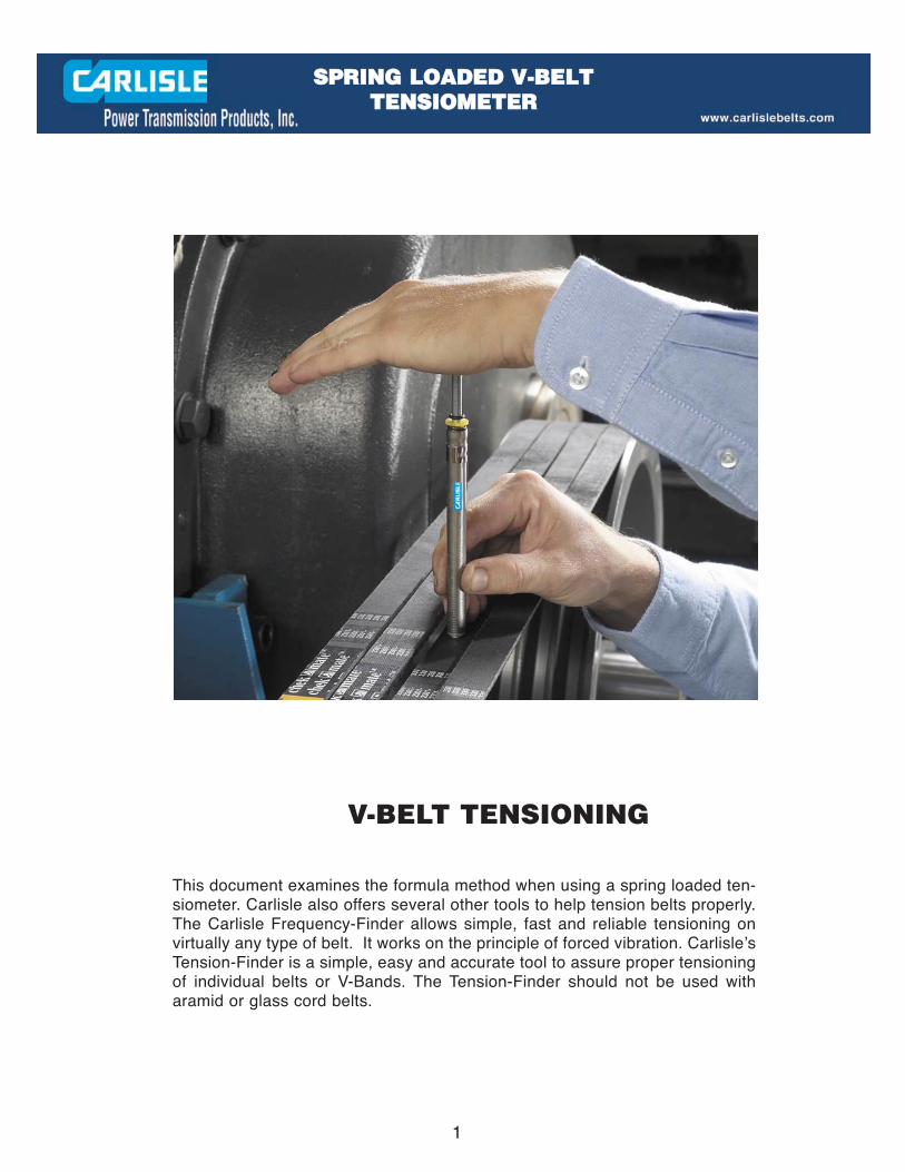
V-BELT TENSIONING
This document examines the formula method when using a spring loaded ten-siometer. Carlisle also offers several other tools to help tension belts properly.The Carlisle Frequency-Finder allows simple, fast and reliable tensioning onvirtually any type of belt. It works on the principle of forced vibration. Carlisle’sTension-Finder is a simple, easy and accurate tool to assure proper tensioningof individual belts or V-Bands. The Tension-Finder should not be used witharamid or glass cord belts.
SSPPRRIINNGG LLOOAADDEEDD VV--BBEELLTT TTEENNSSIIOOMMEETTEERR

2
V-BELT TENSIONING
INTRODUCTIONBecause V-belts operate on the friction principle, multiplied by the mechanical advantage of the wedging principle, propertensioning of v-belts is the single most important factor necessary for long, satisfactory operation. Too little tension will resultin slippage, causing rapid belt and sheave wear, and loss of productivity. Too much tension can result in excessive stress onbelts, bearings, and shafts and reduced efficiency.
However, there is still a wide range of tension within which a drive will operate satisfactorily. The intent is to find this properrange for any V-belt drive.
IMPORTANTAlthough the values in the Average Tensioning Values Table included in this brochure can be used satisfactorily for mostV-belt drives, they are based on drives which are designed using recommended procedures and ratings in the CarlisleEngineering Guide for Industrial V-Belt Drives (102161). They DO NOT, for example, consider drives originallydesigned for wrapped type belts, which are later upgraded to the premium Power-Wedge® Cog-Belt® (3VX, 5VX, 8VX)belts or Gold Ribbon™ Cog-Belt® (AX, BX, CX, DX) belts. In these cases, where known, the values for the wrappedtype Super Power-Wedge® (3V, 5V, 8V) belts or Super Blue Ribbon® (AP, BP, CP, DP) belts should be used. For moreprecise tension values, Carlisle recommends that the “Formula Method” of tensioning described in the EngineeringGuide for Industrial V-Belt Drives be used. Failure to observe the limitations of the Average Tensioning ValuesTable may result in excessive loads on bearings and/or shafts.
GENERAL METHODA few simple rules should be followed to satisfy most drive requirements:
1. For installation, reduce the center distance so the belts may be placed in the sheave grooves without force. Arrange the beltsso that both the top and bottom spans have about the same amount of sag. Apply tension to the belts by increasing the centerdistance until the belts are snug and have a live, springy action when struck with the hand.
2. Operate the drive a few minutes to seat the belts in the sheave grooves. Observe the operation of the drive under its highestload condition (usually starting). A slight bowing of the slack side of the drive indicates adequate tension. If the slack sideremains taut during the peak load, the drive is too tight.
3. Check the tension on a new drive several times during the first 24 hours of operation, by observing the slack side span.
4. Keep the drive free of foreign material which might cause slippage or damage to the belt and sheave surfaces.
5. If a V-belt slips, it is too loose. Increase the tension by increasing the center distance. Never apply belt dressing, as this willdamage the belt and cause early failure.
3
V-BELT TENSIONING(Continued)
Strand Deflection — Formula MethodThis method is based on the fact that the force required to deflect a given span length by a given amount is related to
the tension in the belt. (Note: If the drive uses banded V-belts, use “Belt Elongation Method.” See page 10.
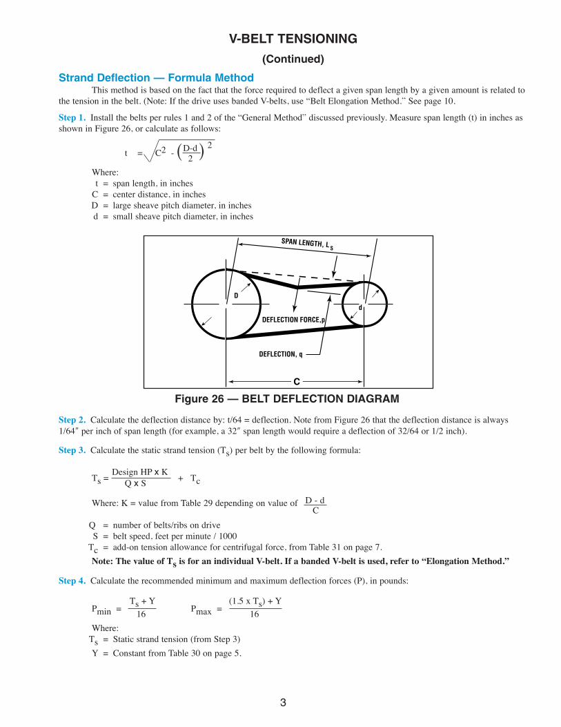
Step 1. Install the belts per rules 1 and 2 of the “General Method” discussed previously. Measure span length (t) in inches asshown in Figure 26, or calculate as follows:
D-d 2t = C2 - 2Where:t = span length, in inches
C = center distance, in inchesD = large sheave pitch diameter, in inchesd = small sheave pitch diameter, in inches
( (
Step 2. Calculate the deflection distance by: t/64 = deflection. Note from Figure 26 that the deflection distance is always1/64″ per inch of span length (for example, a 32″ span length would require a deflection of 32/64 or 1/2 inch).
Step 3. Calculate the static strand tension (Ts) per belt by the following formula:
Design HP x KTs = + TcQ x S
Where: K = value from Table 29 depending on value of D - dC
Q = number of belts/ribs on driveS = belt speed, feet per minute / 1000
Tc = add-on tension allowance for centrifugal force, from Table 31 on page 7.Note: The value of Ts is for an individual V-belt. If a banded V-belt is used, refer to “Elongation Method.”
Step 4. Calculate the recommended minimum and maximum deflection forces (P), in pounds:
Ts + Y (1.5 x Ts) + YPmin = 16 Pmax = 16Where:
Ts = Static strand tension (from Step 3)Y = Constant from Table 30 on page 5.
Figure 26 — BELT DEFLECTION DIAGRAM
SPAN LENGTH, L
C
S
DEFLECTION FORCE,p
DEFLECTION, q
D
d

4
V-BELT TENSIONING(Continued)Table 29 Factors Table
Arc of (D-d)ContactC
A B H K M N O(degrees) (Cq)
180 0.000 — 1.000 2.000 24.750 1.000 1.00 0.75179 0.017 57.297 1.000 2.000 24.843 1.000 1.00 0.75178 0.035 28.649 1.000 2.000 24.937 1.000 1.00 0.76177 0.052 19.101 1.000 1.999 25.032 1.000 0.99 0.76176 0.070 14.327 0.999 1.999 25.129 0.999 0.99 0.76175 0.087 11.463 0.999 1.998 25.227 0.999 0.99 0.76174 0.105 9.554 0.998 1.997 25.326 0.999 0.99 0.77173 0.122 8.190 0.998 1.996 25.427 0.998 0.98 0.77172 0.140 7.168 0.997 1.995 25.529 0.998 0.98 0.77171 0.157 6.373 0.996 1.994 25.632 0.997 0.9 0.77170 0.174 5.737 0.996 1.992 25.737 0.996 0.98 0.77169 0.192 5.217 0.995 1.991 25.844 0.995 0.97 0.78168 0.209 4.783 0.994 1.989 25.952 0.995 0.97 0.78167 0.226 4.417 0.993 1.987 26.061 0.994 0.97 0.78166 0.244 4.103 0.992 1.985 26.172 0.993 0.97 0.78165 0.261 3.831 0.991 1.983 26.285 0.992 0.96 0.79164 0.278 3.593 0.990 1.981 26.399 0.990 0.96 0.79163 0.296 3.383 0.988 1.978 26.515 0.989 0.96 0.79162 0.313 3.196 0.987 1.975 26.633 0.988 0.96 0.79161 0.330 3.029 0.986 1.973 26.752 0.987 0.95 0.80160 0.347 2.879 0.984 1.970 26.873 0.985 0.95 0.80159 0.364 2.744 0.983 1.967 26.996 0.984 0.95 0.80158 0.382 2.620 0.981 1.963 27.120 0.982 0.95 0.80157 0.399 2.508 0.979 1.960 27.247 0.980 0.94 0.81156 0.416 2.405 0.977 1.956 27.375 0.979 0.94 0.81155 0.433 2.310 0.975 1.953 27.505 0.977 0.94 0.81154 0.450 2.223 0.973 1.949 27.638 0.975 0.93 0.81153 0.467 2.142 0.971 1.945 27.772 0.973 0.93 0.81152 0.484 2.067 0.969 1.941 27.908 0.971 0.93 0.82151 0.501 1.997 0.967 1.936 28.046 0.969 0.93 0.82150 0.518 1.932 0.965 1.932 28.187 0.967 0.92 0.82149 0.534 1.871 0.962 0.927 28.329 0.965 0.92 0.82148 0.551 1.814 0.960 1.923 28.474 0.963 0.92 0.83147 0.568 1.760 0.957 1.918 28.621 0.961 0.91 0.83146 0.585 1.710 0.954 1.913 28.771 0.959 0.91 0.83145 0.601 1.663 0.952 1.907 28.922 0.956 0.91 0.83144 0.618 1.618 0.949 1.902 29.076 0.954 0.91 0.83143 0.635 1.576 0.946 1.897 29.233 0.952 0.90 0.84142 0.651 1.536 0.943 1.891 29.392 0.949 0.90 0.84141 0.668 1.498 0.940 1.885 29.553 0.947 0.90 0.84
Arc of (D-d)ContactC
A B H K M N O(degrees) (Cq)
140 0.684 1.462 0.936 1.879 29.718 0.944 0.89 0.84139 0.700 1.428 0.933 1.873 29.884 0.942 0.89 0.84138 0.717 1.395 0.930 1.867 30.054 0.939 0.89 0.85137 0.733 1.364 0.926 1.861 30.226 0.936 0.88 0.85136 0.749 1.335 0.922 1.854 30.402 0.934 0.88 0.85135 0.765 1.307 0.919 1.848 30.580 0.931 0.88 0.85134 0.781 1.280 0.915 1.841 30.761 0.928 0.87 0.85133 0.797 1.254 0.911 1.834 30.945 0.925 0.87 0.86132 0.813 1.229 0.907 1.827 31.132 0.923 0.87 0.86131 0.829 1.206 0.903 1.820 31.323 0.920 0.86 0.86130 0.845 1.183 0.898 1.813 31.516 0.917 0.86 0.86129 0.861 1.161 0.894 1.805 31.713 0.914 0.86 0.86128 0.877 1.141 0.889 1.798 31.914 0.911 0.85 0.85127 0.892 1.121 0.885 1.790 32.118 0.908 0.85 0.85126 0.908 1.101 0.880 1.782 32.325 0.905 0.84 0.84125 0.939 1.065 0.870 1.766 32.752 0.899 0.84 0.84123 0.954 1.048 0.864 1.758 32.970 0.896 0.83 0.83122 0.970 1.031 0.859 1.749 33.193 0.893 0.83 0.83121 0.985 1.015 0.853 1.741 33.420 0.890 0.83 0.83120 1.000 1.000 0.847 1.732 33.651 0.887 0.82 0.82119 1.015 0.985 0.841 1.723 33.886 0.884 0.82 0.82118 1.030 0.971 0.835 1.714 34.126 0.880 0.81 0.81117 1.045 0.957 0.829 1.705 34.370 0.877 0.81 0.81116 1.060 0.944 0.822 1.696 34.618 0.874 0.81 0.81115 1.075 0.931 0.815 1.687 34.871 0.871 0.80 0.80114 1.089 0.918 0.808 1.677 35.130 0.868 0.80 0.80113 1.104 0.906 0.801 1.668 35.393 0.865 0.79 0.79112 1.118 0.894 0.793 1.658 35.661 0.861 0.79 0.79111 1.133 0.883 0.785 1.648 35.934 0.858 0.79 0.79110 1.147 0.872 0.776 1.638 36.213 0.855 0.78 0.78109 1.161 0.861 0.767 1.628 36.497 0.852 0.78 0.78108 1.176 0.851 0.757 1.618 36.787 0.849 0.77 0.77107 1.190 0.841 0.747 1.608 37.083 0.845 0.77 0.77106 1.204 0.831 0.736 1.597 37.385 0.842 0.77 0.77105 1.218 0.821 0.724 1.587 37.693 0.839 0.76 0.76104 1.231 0.812 0.710 1.576 38.008 0.836 0.76 0.76103 1.245 0.803 0.694 1.565 38.328 0.833 0.75 0.75102 1.259 0.795 0.675 1.554 38.656 0.830 0.75 0.75101 1.272 0.786 0.644 1.543 38.991 0.826 0.74 0.74

5
V-BELT TENSIONING (Continued)
TABLE 30 - FACTORS Cc & Y
BELT Cc Cc YCROSS SINGLE BANDED
SECTION BELTS BELTS
A 0.72 - 6.00AP 0.72 0.86 5.00AX 0.68 0.81 6.00
B 0.99 - 9.00BP 1.09 1.36 8.00BX 0.95 1.17 9.00
C 2.09 - 18.00CP 1.84 2.24 18.00CX 1.69 - 19.00
DP 3.65 4.19 28.00DX 3.83 4.78 40.00
3VX 0.55 0.47 4.005VX/5V 1.25 1.32 11.00
8V 2.95 3.46 25.008VX 2.95 3.46 30.00
NOTE: For drives using only one belt, and at least one shaft is free to turn, use the following for the deflection forces (P):
Ts + tLr (1.5xTs) +
tLYPmin =
16Pmax =
16
Where: t = span length, inches (from step 1)L = belt pitch length, inchesY = constant from Table 30 above
STEP 5Tension the V-belts by this procedure:
a) Using a Carlisle Tensiometer (part no. 102761), or other suitable spring scale, apply force to ONE belt of the drive, perpen-dicular to the span at its mid-point, as shown in figure 27. See Page 13 for the Tensiometer instructions.
b) Measure the deflecting force being applied when the belt has been deflected the distance calculated in Step 2 (use an adja-cent belt as reference point; on single belt drives, use straight edge or taut string across sheaves). The measured force shouldbe between the values of Pmin and Pmax calculated in Step 4. If the measured force is outside these values, adjust center distanceto increase or reduce tension, and repeat above procedure. On multiple belt drives an average of readings on each belt isrecommended.
NOTE: If new belts are being installed for the first time, it is permissible to tension as much as 1.33 x Pmax to allow forinitial stretch and seating in the grooves.
STEP 6During the first 24 hours of operation, it is advisable to repeat the procedure in Step 5 at least once.
6
V-BELT TENSIONING (Continued)
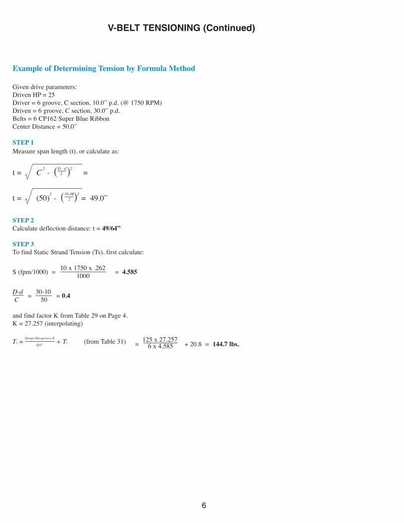
Example of Determining Tension by Formula Method
Given drive parameters:Driven HP = 25Driver = 6 groove, C section, 10.0” p.d. (@ 1750 RPM)Driven = 6 groove, C section, 30.0” p.d.Belts = 6 CP162 Super Blue RibbonCenter Distance = 50.0”
STEP 1Measure span length (t), or calculate as:
t = C2
- (D - d2 )2 =
t = (50)2 - (30-102
0)2 = 49.0”
STEP 2Calculate deflection distance: t = 49/64”
STEP 3To find Static Strand Tension (Ts), first calculate:
10 x 1750 x .262S (fpm/1000) = 1000 = 4.585
D-d 30-10C = 50 = 0.4
and find factor K from Table 29 on Page 4.K = 27.257 (interpolating)
Ts = Design Horspowerx K+ Tc (from Table 31) 125 x 27.257
QxS = 6 x 4.585 + 20.8 = 144.7 lbs.
7
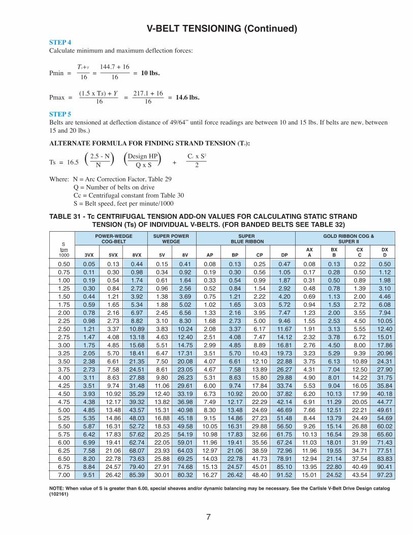
V-BELT TENSIONING (Continued)STEP 4Calculate minimum and maximum deflection forces:
Ts+Y 144.7 + 16Pmin = 16 = 16 = 10 lbs.
(1.5 x Ts) + Y 217.1 + 16Pmax = 16 = 16 = 14.6 lbs.
STEP 5Belts are tensioned at deflection distance of 49/64” until force readings are between 10 and 15 lbs. If belts are new, between15 and 20 lbs.)
ALTERNATE FORMULA FOR FINDING STRAND TENSION (Ts):
2.5 - N Design HP Cc x S2
Ts = 16.5 ( N ) ( Q x S ) + 2
Where: N = Arc Correction Factor, Table 29Q = Number of belts on driveCc = Centrifugal constant from Table 30S = Belt speed, feet per minute/1000
TABLE 31 - Tc CENTRIFUGAL TENSION ADD-ON VALUES FOR CALCULATING STATIC STRANDTENSION (Ts) OF INDIVIDUAL V-BELTS. (FOR BANDED BELTS SEE TABLE 32)
POWER-WEDGE SUPER POWER SUPER GOLD RIBBON COG &
S COG-BELT WEDGE BLUE RIBBON SUPER II
fpm AX BX CX DX1000 3VX 5VX 8VX 5V 8V AP BP CP DP A B C D
0.50 0.05 0.13 0.44 0.15 0.41 0.08 0.13 0.25 0.47 0.08 0.13 0.22 0.500.75 0.11 0.30 0.98 0.34 0.92 0.19 0.30 0.56 1.05 0.17 0.28 0.50 1.121.00 0.19 0.54 1.74 0.61 1.64 0.33 0.54 0.99 1.87 0.31 0.50 0.89 1.981.25 0.30 0.84 2.72 0.96 2.56 0.52 0.84 1.54 2.92 0.48 0.78 1.39 3.101.50 0.44 1.21 3.92 1.38 3.69 0.75 1.21 2.22 4.20 0.69 1.13 2.00 4.461.75 0.59 1.65 5.34 1.88 5.02 1.02 1.65 3.03 5.72 0.94 1.53 2.72 6.082.00 0.78 2.16 6.97 2.45 6.56 1.33 2.16 3.95 7.47 1.23 2.00 3.55 7.942.25 0.98 2.73 8.82 3.10 8.30 1.68 2.73 5.00 9.46 1.55 2.53 4.50 10.052.50 1.21 3.37 10.89 3.83 10.24 2.08 3.37 6.17 11.67 1.91 3.13 5.55 12.402.75 1.47 4.08 13.18 4.63 12.40 2.51 4.08 7.47 14.12 2.32 3.78 6.72 15.013.00 1.75 4.85 15.68 5.51 14.75 2.99 4.85 8.89 16.81 2.76 4.50 8.00 17.863.25 2.05 5.70 18.41 6.47 17.31 3.51 5.70 10.43 19.73 3.23 5.29 9.39 20.963.50 2.38 6.61 21.35 7.50 20.08 4.07 6.61 12.10 22.88 3.75 6.13 10.89 24.313.75 2.73 7.58 24.51 8.61 23.05 4.67 7.58 13.89 26.27 4.31 7.04 12.50 27.904.00 3.11 8.63 27.88 9.80 26.23 5.31 8.63 15.80 29.88 4.90 8.01 14.22 31.754.25 3.51 9.74 31.48 11.06 29.61 6.00 9.74 17.84 33.74 5.53 9.04 16.05 35.844.50 3.93 10.92 35.29 12.40 33.19 6.73 10.92 20.00 37.82 6.20 10.13 17.99 40.184.75 4.38 12.17 39.32 13.82 36.98 7.49 12.17 22.29 42.14 6.91 11.29 20.05 44.775.00 4.85 13.48 43.57 15.31 40.98 8.30 13.48 24.69 46.69 7.66 12.51 22.21 49.615.25 5.35 14.86 48.03 16.88 45.18 9.15 14.86 27.23 51.48 8.44 13.79 24.49 54.695.50 5.87 16.31 52.72 18.53 49.58 10.05 16.31 29.88 56.50 9.26 15.14 26.88 60.025.75 6.42 17.83 57.62 20.25 54.19 10.98 17.83 32.66 61.75 10.13 16.54 29.38 65.606.00 6.99 19.41 62.74 22.05 59.01 11.96 19.41 35.56 67.24 11.03 18.01 31.99 71.436.25 7.58 21.06 68.07 23.93 64.03 12.97 21.06 38.59 72.96 11.96 19.55 34.71 77.516.50 8.20 22.78 73.63 25.88 69.25 14.03 22.78 41.73 78.91 12.94 21.14 37.54 83.836.75 8.84 24.57 79.40 27.91 74.68 15.13 24.57 45.01 85.10 13.95 22.80 40.49 90.417.00 9.51 26.42 85.39 30.01 80.32 16.27 26.42 48.40 91.52 15.01 24.52 43.54 97.23
NOTE: When value of S is greater than 6.00, special sheaves and/or dynamic balancing may be necessary. See the Carlisle V-Belt Drive Design catalog(102161)

8
S Wedge-Band Super Vee-Band Gold Ribbon Cog-Bandfpm
1000 R3V R5V R8V RBP RCP RDP RBX RCX RDX0.50 0.06 0.16 0.47 0.17 0.29 0.54 0.16 0.26 0.570.75 0.14 0.37 1.07 0.39 0.66 1.21 0.36 0.59 1.281.00 0.25 1.03 2.97 1.08 1.82 3.35 1.00 1.64 3.561.25 0.40 1.03 2.97 1.08 1.82 3.35 1.00 1.64 3.561.50 0.57 1.48 4.27 1.55 2.62 4.82 1.44 2.36 5.12
1.75 0.78 2.02 5.81 2.11 3.57 6.57 1.96 3.21 6.972.00 1.02 2.64 7.59 2.76 4.66 8.58 2.55 4.19 9.112.25 1.29 3.34 9.61 3.49 5.90 10.85 3.23 5.31 11.532.50 1.59 4.12 11.86 4.31 7.28 13.40 3.99 6.55 14.232.75 1.92 4.99 14.35 5.22 8.81 16.21 4.83 7.93 17.22
3.00 2.29 5.94 17.08 6.21 10.48 19.29 5.75 9.43 20.503.25 2.69 6.97 20.05 7.29 12.30 22.64 6.74 11.07 24.063.50 3.12 8.08 23.25 8.45 14.27 26.26 7.82 12.84 27.903.75 3.58 9.28 26.69 9.71 16.38 30.15 8.98 14.74 32.034.00 4.07 10.56 30.37 11.04 18.63 34.30 10.21 16.77 36.44
4.25 4.60 11.92 34.28 12.47 21.04 38.72 11.53 18.93 41.144.50 5.15 13.36 38.43 13.98 23.58 43.41 12.93 21.23 46.124.75 5.74 14.89 42.82 15.57 26.28 48.37 14.40 23.65 51.395.00 6.36 16.50 47.45 17.25 29.12 53.60 15.96 26.20 56.945.25 7.01 18.19 52.31 19.02 32.10 59.09 17.69 28.89 62.77
5.50 7.70 19.96 57.41 20.88 35.23 64.85 19.31 31.71 68.905.75 8.41 21.82 62.75 22.82 38.51 70.88 21.11 34.66 75.306.00 9.16 23.76 68.33 24.85 41.93 77.18 22.98 37.73 81.996.25 9.94 25.78 74.14 26.96 45.49 83.74 24.94 40.94 88.976.50 10.75 27.88 80.19 29.16 49.21 90.58 26.97 44.29 96.23
6.75 11.60 30.07 86.47 31.45 53.06 97.68 29.09 47.76 103.777.00 12.47 32.34 93.00 33.82 57.07 105.05 31.28 51.36 111.60
V-BELT TENSIONING (Continued)
TABLE 32 - Tc CENTRIFUGAL TENSION ADD-ON VALUES FOR CALCULATING STATIC STRAND TENSION (Ts) OF BANDED V-BELTS. (FOR INDIVIDUAL V-BELTS SEE TABLE 31)
When value of S is greater than 6.00, special sheaves and/ordynamic balancing may be necessary - see the Carlisle V BeltDrive design catalog 102161
AVERAGE TENSIONING TABLES
Although the Formula Method is recommended for the most accurate means of determining V-Belt tension, Table 33 may be usedsatisfactorily for most drives. However, these values are based on drives which are designed using recommended procedures andratings in this catalog for the belt types and cross-sections indicated in the tables. They do NOT, for example, consider drivesoriginally designed for wrapped-type belts, which are later upgraded to the premium Power-Wedge Cog-Belt or Gold Ribbon Cog-Belt. In these cases, where known, the values for the wrapped-type Super Power-Wedge or Super Blue Ribbon should be used.
Failure to observe these limitations of the tables may result in excessive loads on bearings and/or shafts.
NOTE

9
V-BELT TENSIONING (Continued)
TABLE 33 AVERAGE TENSIONING VALUES (RECOMMENDED MINIMUM FORCE PER BELT)V-Belt V-Belt Small Sheave Deflection Force for Drive Speed Ratio (lbs.)Type Section Speed Range Diameter 1.00 1.5 2.0 4.0 & over
1800-3600 3.0 2.0 2.3 2.4 3.3A 1800-3600 4.0 2.6 2.8 3.0 3.3
AP 1800-3600 5.0 3.0 3.3 3.4 3.71800-3600 7.0 3.5 3.7 3.8 4.31200-1800 4.6 3.7 4.3 4.5 5.0
Super II B 1200-1800 5.0 4.1 4.6 4.8 5.6BP 1200-1800 6.0 4.8 5.3 5.5 6.3
1200-1800 8.0 5.7 6.2 6.4 7.2900-1800 7.0 6.5 7.0 8.0 9.0
Super C 900-1800 9.0 8.0 9.0 10.0 11.0Blue Ribbon CP 900-1800 12.0 10.0 11.0 12.0 13.0
700-1500 16.0 12.0 13.0 13.0 14.0900-1500 12.0 13.0 15.0 16.0 17.0900-1500 15.0 16.0 18.0 19.0 21.0
DP 700-1200 18.0 19.0 21.0 22.0 24.0700-1200 22.0 22.0 23.0 24.0 26.01800-3600 3.0 2.5 2.8 3.0 3.31800-3600 4.0 3.3 3.6 3.8 4.2
AX 1800-3600 5.0 3.7 4.1 4.3 4.61800-3600 7.0 4.3 4.6 4.8 5.31200-1800 4.6 5.2 5.8 6.0 6.91200-1800 5.0 5.4 6.0 6.3 7.1
BX 1200-1800 6.0 6.0 6.4 6.7 7.7Gold Ribbon 1200-1800 8.0 6.6 7.1 7.5 8.2
Cog-Belt 900-1800 7.0 10.0 11.0 12.0 13.0900-1800 9.0 11.0 12.0 13.0 14.0
CX 900-1800 12.0 12.0 13.0 13.0 14.0700-1500 16.0 13.0 14.0 14.0 15.0900-1500 12.0 16.0 18.0 19.0 20.0900-1500 15.0 19.0 21.0 22.0 24.0
DX 700-1200 18.0 22.0 24.0 25.0 27.0700-1200 22.0 25.0 27.0 28.0 30.01200-3600 2.2 2.2 2.5 2.7 3.01200-3600 2.5 2.6 2.9 3.1 3.6
3VX 1200-3600 3.0 3.1 3.5 3.7 4.21200-3600 4.1 3.9 4.3 4.5 5.11200-3600 5.3 4.6 4.9 5.1 5.71200-3600 6.9 5.0 5.4 5.6 6.21200-3600 4.4 6.5 7.5 8.0 9.0
Power- 1200-3600 5.2 8.0 9.0 9.5 10.0Wedge 5VX 1200-3600 6.3 9.5 10.0 11.0 12.0
Cog-Belt 1200-3600 7.1 10.0 11.0 12.0 13.0900-1800 9.0 12.0 13.0 14.0 15.0900-1800 14.0 14.0 15.0 16.0 17.0900-1800 12.5 18.0 21.0 23.0 25.0900-1800 14.0 21.0 23.0 24.0 28.0
8VX 700-1500 17.0 24.0 26.0 28.0 30.0700-1200 21.2 28.0 30.0 32.0 34.0400-1000 24.8 31.0 32.0 34.0 36.0900-1800 7.1 8.5 9.5 10.0 11.0900-1800 9.0 10.0 11.0 12.0 13.0
5V 900-1800 14.0 12.0 13.0 14.0 15.0Super 700-1200 21.2 14.0 15.0 16.0 17.0Power- 900-1800 12.5 18.0 21.0 23.0 25.0Wedge 900-1800 14.0 21.0 23.0 24.0 28.0
8V 700-1500 17.0 24.0 26.0 28.0 30.0700-1200 21.2 28.0 30.0 32.0 34.0400-1000 24.8 31.0 32.0 34.0 36.0

10
V-BELT TENSIONING (Continued)
USE OF TABLES(NOTE: For banded V-Belts, Use the Elongation Method)
STEP 1Install the belts per rules 1 and 2 of the “General Method” discussed previously. Measure span length (t) in inches, or calcu-late per “Formula Method”.
STEP 2Calculate the deflection distance by t/64 = deflection.
STEP 3Depending on the belt type and cross section, and the small sheave diameter and speed, locate the Minimum Deflection Force(Pmin) in the appropriate drive ratio column of Table 33 on Page 9. For intermediate diameters or ratios, use interpolation.
Maximum Deflection Force = 1.5 x minimum (for new belts, 2.0 x Minimum can be used.)
STEP 4Tension belts per Steps 5 & 6 of “Formula Method”. When using Carlisle Tensiometer (part no. 102761) see instructions onpage 13.
ELONGATION METHODThis method is recommended for tensioning Super Vee-Band, Wedge-Band and Gold Ribbon Cog-Band drives where largerdeflection forces make the use of other methods impractical.
Because belt elongation is related to the tension causing it, tape-measured lengths, both slack and tight, can be used to obtainproper Vee-Band tension.
VEE-BAND INSTALLATION AND TENSIONING PROCEDURE
STEP 1Check sheaves to make sure they are properly aligned and that the grooves are not excessively worn (they should not bedished out more than 1/64”).
STEP 2Decrease the center distance until the Vee-Band(s) can be easily slipped into the sheave grooves. Forcing the belts on candamage the load-carrying cords and cause premature failure.
STEP 3With the Vee-Band(s) still on the drive at no tension,tape their outside circumference (slack O.C.).
NOTE: If you are tensioning a used belt, decrease the center distance until there is no tension on it; then tape the out-side circumference.

11
V-BELT TENSIONING (Continued)
STEP 4Find the required static tension (Ts) per individual strand (rib) using the formula:
Design HP x KTs = Q x S + Tc
Where: K = value from table 29 (page 4) depending on D-dC
Q = number of beltsS = belt speed, fpm/1000Tc = add-on tension allowance for centrifugal force (See Table 32 page 8)
STEP 5Find a range of recommended Static Strand Tensions:Lower value = Ts (from Step 4)Upper value = 1.5 x Ts
STEP 6Calculate minimum and maximum elongation band lengths for use in tensioning drive:a. From table 34, find length multipliers corresponding to the lower and upper values of Ts in Step 5.b. Multiply the slack O.C. found in Step 3 by the multipliers to find the minimum and maximum elongated band lengths.
STEP 7Increase the drive center distance until a tape measurement of the band(s) O.C. is between the two values calculated for elon-gated band lengths in Step 6(b).
STEP 8Re-tension as required. A new Vee-Band may lose tension rapidly during the run-in period and will probably need re-tensioning.A Vee-Band that has been on a drive for some time may also require re-tensioning due to tension decay from normal use andwear.

12
V-BELT TENSIONING (Continued)
TABLE 34 BELT LENGTH MULTIPLIERS FOR TENSIONING BANDED V-BELTS BY THEELONGATION METHOD
Ts Wedge-Band Super Vee-Band Gold Label Cog-BandPer R3VX R5V R8V RBP RCP RDP RBX RCX RCX RDX
Strand All R5XV R5V R8VX R8V RBP144 over RCP144 over All All up thru over All(lbs.) & under RBP144 & under RCP144 RBX210 CX210
10 1.0012 1.0007 1.0006 1.0003 1.0007 1.0006 1.0007 1.0005 1.0007 1.0004 1.0006 1.0005 1.0008 1.000712 1.0014 1.0009 1.0008 1.0004 1.0009 1.0008 1.0009 1.0006 1.0008 1.0005 1.0008 1.0006 1.0008 1.000814 1.0016 1.0010 1.0009 1.0004 1.0010 1.0009 1.0011 1.0007 1.0009 1.0006 1.0009 1.0007 1.0011 1.001016 1.0019 1.0011 1.0010 1.0005 1.0011 1.0010 1.0012 1.0008 1.0011 1.0007 1.0010 1.0008 1.0012 1.001118 1.0021 1.0013 1.0012 1.0005 1.0013 1.0012 1.0014 1.0009 1.0012 1.0008 1.0012 1.0009 1.0014 1.0012
20 1.0023 1.0014 1.0013 1.0006 1.0014 1.0013 1.0016 1.0010 1.0013 1.0009 1.0003 1.0010 1.0015 1.001424 1.0028 1.0017 1.0016 1.0007 1.0017 1.0016 1.0019 1.0012 1.0016 1.0010 1.0015 1.0012 1.0018 1.001732 1.0038 1.0023 1.0021 1.0009 1.0022 1.0021 1.0027 1.0016 1.0021 1.0014 1.0021 1.0015 1.0024 1.002236 1.0042 1.0026 1.0023 1.0011 1.0025 1.0024 1.0031 1.0018 1.0024 1.0016 1.0023 1.0017 1.0026 1.002440 1.0047 1.0029 1.0026 1.0012 1.0028 1.0026 1.0035 1.0020 1.0026 1.0017 1.0026 1.0019 1.0029 1.0027
45 1.0053 1.0032 1.0029 1.0013 1.0031 1.0030 1.0040 1.0023 1.0030 1.0019 1.0029 1.0022 1.0033 1.003050 1.0060 1.0036 1.0033 1.0015 1.0034 1.0033 1.0046 1.0025 1.0033 1.0022 1.0032 1.0024 1.0036 1.003355 1.0066 1.0039 1.0036 1.0016 1.0037 1.0036 1.0052 100.28 1.0036 1.0024 1.0036 1.0027 1.0039 1.003760 1.0072 1.0043 1.0039 1.0018 1.0040 1.0040 1.0058 1.0030 1.0039 1.0026 1.0039 1.0029 1.0043 1.004065 1.0079 1.0047 1.0043 1.0019 1.0044 1.0043 1.0064 1.0033 1.0043 1.0028 1.0042 1.0032 1.0046 1.0043
70 1.0085 1.0050 1.0046 1.0021 1.0047 1.0047 1.0071 1.0035 1.0046 1.0031 1.0046 1.0035 1.0049 1.004675 1.0092 1.0054 1.0049 1.0022 1.0050 1.0050 1.0077 1.0038 1.0049 1.0033 1.0049 1.0037 1.0053 1.004980 1.0098 1.0058 1.0053 1.0024 1.0053 1.0054 1.0084 1.0040 1.0052 1.0035 1.0052 1.0040 1.0056 1.005285 1.0105 1.0061 1.0056 1.0025 1.0056 1.0057 1.0092 1.0043 1.0055 1.0037 1.0056 1.0042 1.0059 1.005590 1.0111 1.0065 1.0060 1.0027 1.0059 1.0061 1.0099 1.0045 10..58 1.0040 1.0059 1.0045 1.0062 1.0058
95 1.0118 1.0069 1.0063 1.0028 1.0062 1.0065 1.0106 1.0048 1.0062 1.0042 1.0062 1.0048 1.0065 1.0060100 1.0125 1.0072 1.0066 1.0030 1.0065 1.0068 1.0114 1.0050 1.0065 1.0044 1.0066 1.0050 1.0068 1.0063120 1.0152 1.0087 1.0080 1.0035 1.0076 1.0083 1.0147 1.0061 1.0077 1.0053 1.0079 1.0061 1.0080 1.0074140 1.0181 1.0102 1.0094 1.0041 1.0087 1.0098 1.0183 1.0071 1.0090 1.0063 1.0093 1.0072 1.0091 1.0085160 1.0210 1.0117 1.0109 1.0047 1.0097 1.0113 1.0221 1.0082 1.0102 1.0072 1.0107 1.0083 1.0102 1.0095
180 1.0240 1.0133 1.0123 1.0053 1.0107 1.0129 1.0263 1.0092 1.0114 1.0082 1.0121 1.0094 1.0112 1.0104200 1.0271 1.0148 1.0138 1.0059 1.0116 1.0145 1.0307 1.0103 1.0126 1.0092 1.0136 1.0106 1.0122 1.0114240 10.336 1.0179 1.0168 1.0071 1.0134 1.078 1.0402 1.0125 1.0150 1.0112 1.0165 1.0129 1.0140 1.0131280 1.0404 1.0211 1.0198 1.0083 1.0150 1.0213 1.0505 1.0149 1.0174 1.0132 1.0195 1.0154 1.0158 1.0146320 1.0475 1.0243 1.0229 1.0095 1.0165 1.0249 - 1.0174 1.0198 1.0153 1.0225 10.179 1.0174 1.0161
360 1.0550 1.0276 1.0261 1.0106 1.0179 1.0286 - 1.0200 1.0222 1.0175 1.0256 1.0206 1.0190 1.0175400 - 1.0309 1.0294 1.0118 1.0193 1.0325 - 1.0228 1.0246 1.0197 1.0288 1.0233 1.0206 1.0187450 - 1.0351 1.0366 1.0133 1.0209 1.0375 - 1.0266 1.0277 10.226 1.0329 10.268 1.0226 1.0202500 - 1.0394 1.0379 10.148 1.0224 1.0428 - 1.0307 1.0309 1.0255 1.0370 1.0304 1.0247 1.0217550 - 1.0438 1.0423 1.0163 1.0240 1.0482 - 1.0352 1.0343 1.0285 1.0413 1.0342 1.0269 1,9231
600 - 1.0482 1.0468 1.0177 1.0256 1.0539 - 1.0401 1.0377 1.0316 1.0457 1.0381 1.0293 1.0246650 - 1.0528 1.0513 1.0192 1.0273 - - 1.0455 1.0414 1.0348 1.0501 1.0421 1.0320 1.0261700 - - - 1.0207 1.0291 - - 1.0514 1.0452 1.0381 - 1.0463 1.0350 1.0277750 - - - 1.0222 1.0311 - - - 1.0493 1.0414 - 1.0506 1.0384 1.0294800 - - - 1.0237 1.033 - - - 1.0536 1.0449 - - 1.0423 1.0313
850 - - - 1.0251 1.0357 - - - - 1.0484 - - 1.0466 1.0334900 - - - 1.0266 1.0384 - - - - 1.0520 - - 1.0516 1.0358950 - - - 1.0281 .10414 - - - - - - - - 1.0385
1000 - - - 1.0296 1.0448 - - - - - - - - 1.0414

13
INSTRUCTIONS FOR USING THE SPRING LOADED V-BELT TENSIOMETERProcedure for using the Carlisle V-Belt Tensiometer
1. Measure the span length of the drive. (See Figure 27).Set the large “O” ring at 1/64˝ for each inch of belt span. For exam-ple, set the large “O” ring 1/4˝ for a span length of 16˝, at 1/2˝ for aspan length of 32˝, at 1˝ for a span length of 64˝ etc.
2. Set the small “O” ring at zero and press down the CarlisleTensiometer at the center of the belt span (See Figure 28).
a. On a single belt drive, depress the Tensiometer until the large “O”ring is even with the bottom of a straight edge placed on the outsiderims of the two sheaves.
b. On a multiple belt drive, depress the Tensiometer until the large“O” ring is even with the top of the next belt. Measure each belt inthe drive. and take the average reading of all belt tensions.
3. Remove the Tensiometer, and observe that the small “O” ring hasmoved from its original setting at zero to the number of poundsrequired to deflect the belt.
4. Check this reading against the value of Pmin and Pmax calculated using the table of Average Tensioning (page 9).
tt = C2 - ( D-d2 ) 2 h = 64
Where:t = Span length, inchesC = Center distance, inchesD = Larger sheave diameterd = Smaller sheave diameter, inches
*Deflection height h = 1/64 per inch of span5
1015
2025
30LB
DEL.
DEL.
1IN
CHES
INCH
ES2
510
1520
2530
LB
SMALL"O"
RING
LARGE"O"
RING
PLACE THIS ENDAT MID-POINTOF BELT SPAN
HOLD HERE
DEL.
1IN
CHES
2
SPAN LENGTH, L
C
S
DEFLECTION FORCE,p
DEFLECTION, q
D
d
Figure 27 MEASURING DEFLECTION FORCE
Figure 28 V-BELT TENSIOMETER(Part No. 102761)
Part No. Item
102761 AWl 1 single stem belt tension tester
105575 AWl 2 double stem belt tension tester
105576 AWl 3 triple stem belt tension tester

14
Power Transmission Products, Inc.
100629 (Rev.06) © Carlisle Power Transmission Products, Inc.
Customer ServicePhone: (866) 773-2926
Canada Customer ServicePhone: (866) 797-2358