tender for electrical power upgrade at · pdf file3.22 protection of works .....36 3.23...
TRANSCRIPT

TENDER FOR ELECTRICAL POWER UPGRADE AT KENYA
COMMERCIAL BANK’S KENCOM HOUSE BUILDING
NAIROBI
Release Date Friday 13th March 2015
Return Date: Friday 27th March 2015

2
Table of Contents Table of Contents ....................................................................................................................... 2 1 INSTRUCTIONS TO BIDDERS ...................................................................................... 6
1.1 Introduction ................................................................................................................ 6 1.2 Preliminaries and conditions of contract .................................................................... 6 1.3 Format of tender response and other information for contractors ........................... 19
2 COMMERCIAL TERMS AND CONDITIONS ............................................................. 23 2.1 Bank reserves the right to the following .................................................................. 23 2.2 Force Majeure .......................................................................................................... 24 2.3 Termination for Insolvency ...................................................................................... 24 2.4 Termination for Convenience .................................................................................. 24
2.5 Performance Guarantee ............................................................................................ 24 2.6 Time of completion & penalty clause ...................................................................... 25 2.7 Injury to persons, property & Owner’s Indemnity................................................... 25
2.8 Accidents.................................................................................................................. 25 2.9 Labour laws .............................................................................................................. 25 2.10 Cost of tests .............................................................................................................. 25 2.11 Statutory authority obligations, notices, fees charges .............................................. 25
2.12 Work to be done to the satisfaction of The Bank ..................................................... 26 3 GENERAL SPECIFICATIONS ...................................................................................... 26
3.1 Extent of Electrical Installations .............................................................................. 26 3.2 Program for Electrical Engineering Installations ..................................................... 27 3.3 Drawings accompanying the Tender Documents .................................................... 27
3.4 Contract Working Drawings .................................................................................... 28
3.5 Record Drawings (“As Installed Drawings”) .......................................................... 29 3.6 Data Schedule .......................................................................................................... 29 3.7 Maintenance Manuals .............................................................................................. 30
3.8 Builder's Work and Civil Works .............................................................................. 30 3.9 Commissioning of the Electrical Installation ........................................................... 31
3.10 Regulations and Standards ....................................................................................... 31 3.11 Quality of Materials ................................................................................................. 31
3.12 Workmanship ........................................................................................................... 32 3.13 Setting out of work................................................................................................... 33 3.14 Erection and checking of work ................................................................................ 33
3.15 Site performance and acceptance tests ..................................................................... 33
3.16 Test records .............................................................................................................. 34 3.17 Dust, insect and vermin proofing ............................................................................. 34 3.18 Painting and finishing .............................................................................................. 34
3.19 Labels ....................................................................................................................... 35 3.20 Specialist manufacturers .......................................................................................... 35 3.21 Interference with the existing Works ....................................................................... 36 3.22 Protection of Works ................................................................................................. 36 3.23 Sundries.................................................................................................................... 36
3.24 Schedules of technical data ...................................................................................... 36 3.25 Copies of orders ....................................................................................................... 36 3.26 Inspection and tests at Manufacturer's Works ......................................................... 36
4 TECHNICAL SPECIFICATIONS FOR 11KV METAL CLAD
PROTECTION AND METERINGSWITCHGEAR PANEL...................................... 37 4.1 General specifications .............................................................................................. 37

3
4.2 Working stress and equipment/apparatus design ..................................................... 40 5 BASIC REQUIREMENT FOR ELECTRICAL EQUIPMENT ...................................... 42
5.1 Electrical controls, auxiliaries and power supplies .................................................. 42 5.2 Wiring ...................................................................................................................... 45
5.3 Equipment and switchgear earthing ......................................................................... 47 5.4 Materials and workmanship ..................................................................................... 47 5.5 Protection, cleaning and painting ............................................................................. 48 5.6 Drawings .................................................................................................................. 49 5.7 Manufacture of sample panels ................................................................................. 51
5.8 Operating and maintenance instructions .................................................................. 52 5.9 Testing at place of manufacture ............................................................................... 52 5.10 Software requirement ............................................................................................... 54
5.11 Spare parts ................................................................................................................ 54 5.12 Accessories for the switchgear panels ..................................................................... 55 5.13 Packing ..................................................................................................................... 55 5.14 Delivery.................................................................................................................... 55
6 DETAILED TECHNICAL SPECIFICATIONS FOR 11 KV METAL CLAD INDOOR
PROTECTION & METERING SWITCHGEAR PANELS.................................................... 56 6.1 Scope ........................................................................................................................ 56 6.2 References ................................................................................................................ 56
6.3 Construction of each panel....................................................................................... 56 6.4 Circuit breakers ........................................................................................................ 61 6.5 Current transformers ................................................................................................ 63
6.6 Voltage transformers ................................................................................................ 64
6.7 Protection relays....................................................................................................... 65 6.8 Indication and instruments ....................................................................................... 66 6.9 Power cable termination .......................................................................................... 66
6.10 Scope of supply for 11kv protection & metering switchgear panels ....................... 66 6.11 Labelling of the switchgear panels .......................................................................... 66
6.12 Ratings of switchgear panel equipment ................................................................... 67 6.13 Factory acceptance tests (FATs) .............................................................................. 68 6.14 Current Transformer ................................................................................................ 69 6.15 Voltage Transformer ................................................................................................ 69
6.16 Protection Relay Tests ............................................................................................. 70 6.17 Training at the manufacturer’s place ....................................................................... 70 6.18 17.5 kV Circuit Breaker. .......................................................................................... 70
6.19 Training at site ......................................................................................................... 71
6.20 Feeder Protection and Control relay ........................................................................ 71 7 PROTECTION RELAYS, CONTROLS AND MEASURING DEVICES
REQUIREMENTS FOR SWITCHGEAR PANELS .............................................................. 71
7.1 General requirements ............................................................................................... 71 7.2 Bill of materials........................................................................................................ 72 7.3 Protection & metering switchgear panel requirements ............................................ 72 7.4 Protection relays....................................................................................................... 72 7.5 Detailed specifications for relays, measuring and indicating instruments, control
switches and other accessories ............................................................................................. 74 7.6 LV switchboard specifications ................................................................................. 78 7.7 Specifications for distribution transformer – Ground mounted three phase
transformer (2000KVA)....................................................................................................... 81 7.8 Test and factory inspection ...................................................................................... 87

4
7.9 Technical documentation ......................................................................................... 87 8 TECHNICAL SCHEDULE - BIDDERS TO COMPLETE ............................................ 88
8.1 Tender form for Switchboard and associated switchgear ........................................ 88 8.2 Tender form for 11000/433V Transformer (Particulars of equipment) ................... 99
8.3 Factory inspection .................................................................................................. 102 8.4 Criteria for passing technical evaluation................................................................ 102
9 GENERAL CONDITIONS OF CONTRACT ............................................................... 103 9.1 Award of Contract.................................................................................................. 103 9.2 Application of General Conditions of Contract ..................................................... 103
10 APPENDIX .................................................................................................................... 108 APPENDIX A – FORM OF TENDER .............................................................................. 108 APPENDIX B – CERTIFICATE OF COMPLIANCE ..................................................... 109
APPENDIX C – LETTER TO KCB ON THE CONTRACTOR’S LETTERHEAD ....... 110 APPENDIX D – PERFORMANCE SECURITY FORM ................................................. 111 APPENDIX E – BIDDER’S DETAILS ............................................................................ 112 APPENDIX F – BILL OF QUANTITIES ......................................................................... 118

5
TENDER FOR ELECTRICAL POWER UPGRADE AT KENYA COMMERCIAL BANK’S
KENCOM HOUSE BUILDING NAIROBI
ISSUE OF RFP DOCUMENT to prospective bidders
This form is to be completed by persons expressing interest on the above
tender, this page is to be completed and faxed immediately to fax number
+254 20 240977 or a scan copy e-mailed to [email protected]. Firms
that do not register their interest in this manner may not be sent the RFP
addenda should any arise.
Name of Person: ______________________________________
Organization Name: __________________________________
Address: _____________________________________________
Tel No: _______________________________________
Fax No:_______________________________________
Email Address:_______________________________________
Signature:___________________________________________
Date:_______________________________________________

6
1 INSTRUCTIONS TO BIDDERS
1.1 Introduction
The KCB Limited (hereinafter referred to as “the Bank’’) is a leading
commercial bank in the Eastern Africa region, renowned for its diversity and
growth potential. The bank has subsidiary companies - KCB Tanzania limited
based in Tanzania, KCB Uganda based in Uganda, KCB Rwanda based in
Rwanda, KCB Burundi based in Burundi, KCB Sudan based in Sudan.
The Bank has a rich history dating back to 1896 and is the largest commercial
bank in the region with over 300 branches in Kenya, Tanzania, Uganda,
Rwanda, Burundi and Southern Sudan.
The Bank’s vision is to be the Preferred Financial Solutions Provider in Africa
with a Global Reach.
The Bank is in the process of upgrading its existing electrical power distribution
system at its Kencom House Headquarters to meet the present and future
needs of the Bank.
In the recent past, the Bank has undergone tremendous changes in its
operations with the adoption of a one branch network. This has necessitated
consolidation and computerisation of banking services.
The automation and computerisation has resulted in installation of additional
equipment to support the operations. This has resulted in high power
demands straining the current installed capacity. The load is expected to
increase as the Bank operations become even more sophisticated.
This has therefore necessitated the need to upgrade the existing electrical
power distribution system to meet the needs of the ever increasing electrical
power demand.
This document therefore constitutes the formal TENDER FOR ELECTRICAL
POWER UPGRADE AT KENYA COMMERCIAL BANK’S KENCOM HOUSE BUILDING
NAIROBI and is being availed on an open tender basis to Contractors
interested in submitting bids.
1.2 Preliminaries and conditions of contract
ITEM KSHS. CTS.
1.01
Examination of Tender Documents
The tenderer is required to check the pages of
these documents and should he find any missing, or
indistinct, he must inform the Consulting Engineers at
once and have the same rectified. The tenderers
shall ensure that all ambiguities, doubts or obscure
points or details are clarified with the Consulting
Engineers before submission of his tender, as no
claims for alleged deficiencies in information given
shall be considered after the tender return date.

7
1.02
Discrepancies
The Contractor shall include all work either shown
on the Contract Drawings, Specification or detailed
in the Schedules. No claim for extra cost shall be
considered for work which has been shown on the
Drawings, Specification or in the Schedules alone.
1.03 Conditions of Contract Agreement
The Contractor shall be required to enter into a
Contract with the Client or his Representative.
The conditions of the Contract between the
Client/Client’s Representative and the Contractor
as hereinafter defined shall be the latest edition of
the Agreement and Schedule of Conditions of
Building Contract published by the Kenya
Association of Building and Civil Engineering
Contractors with sanction of the Architectural
Association of Kenya and The Kenya Institute of
Engineers as particularly modified and amended
hereinafter. For the purpose of this Contract the
Agreement and Schedule of Conditions and any
such modifications and amendments shall be read
and construed together. In the event of
discrepancy the modifications and amendment
shall prevail.
1.04 Definition
The following terms and expressions used in the
Contract Documents shall have the following
meaning:-
The Employer/ shall Mean
Kenya Commercial Bank
P.O. Box 48400 00100,
Nairobi
Electrical consultant/ shall Mean
Aberdare Engineering
P.O. Box 73604-00200
Nairobi

8
Total carried to collection page
A/1
ITEM KSHS. CTS.
The Builder shall mean The firm(if any)
appointed
to carry out the building works.
The Contractor Shall mean the person or persons,
partnership,
firm or company whose tender
for the Contract Works has been
accepted, and who has signed
the Contract and shall include his
or their heirs, executors,
administrators, assigns, successors
and duly appointed
representatives
Works: The expression “Work” or “Works”
shall mean the material and
plant to be provided and labours
to be performed by the
Contractor in fulfillment of the
terms of this Specification and of
any Contract made for the
purpose between himself and
the Client.
Contract
Drawings: shall mean those drawings listed
in schedules or referred to in and
forming part of this Specification.
Working
Drawings: shall mean those drawings which
are to be prepared by the
Contractor as described in this
Specification.
Record
Drawings: shall mean those drawings which
are to be prepared by the
Contractor after completion of
work “As installed” or other
records of this work as described
in this Specification.
9
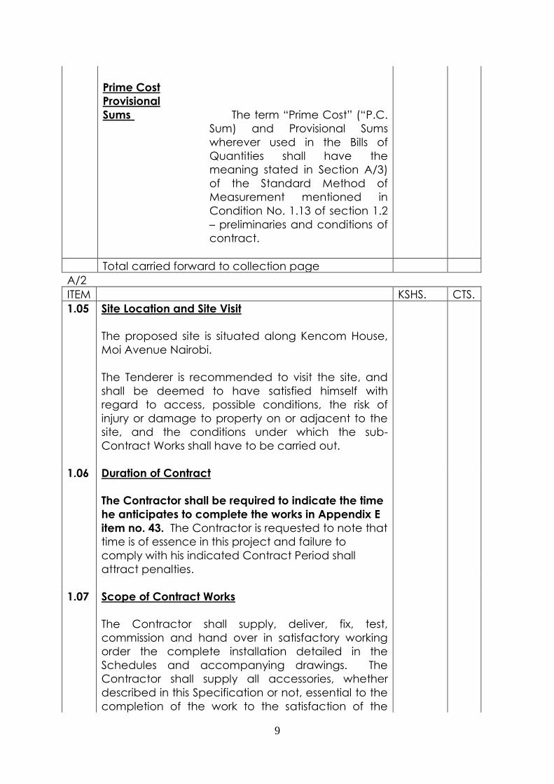
Prime Cost
Provisional
Sums The term “Prime Cost” (“P.C.
Sum) and Provisional Sums
wherever used in the Bills of
Quantities shall have the
meaning stated in Section A/3)
of the Standard Method of
Measurement mentioned in
Condition No. 1.13 of section 1.2
– preliminaries and conditions of
contract.
Total carried forward to collection page
A/2
ITEM KSHS. CTS.
1.05 Site Location and Site Visit
The proposed site is situated along Kencom House,
Moi Avenue Nairobi.
The Tenderer is recommended to visit the site, and
shall be deemed to have satisfied himself with
regard to access, possible conditions, the risk of
injury or damage to property on or adjacent to the
site, and the conditions under which the sub-
Contract Works shall have to be carried out.
1.06 Duration of Contract
The Contractor shall be required to indicate the time
he anticipates to complete the works in Appendix E
item no. 43. The Contractor is requested to note that
time is of essence in this project and failure to
comply with his indicated Contract Period shall
attract penalties.
1.07 Scope of Contract Works
The Contractor shall supply, deliver, fix, test,
commission and hand over in satisfactory working
order the complete installation detailed in the
Schedules and accompanying drawings. The
Contractor shall supply all accessories, whether
described in this Specification or not, essential to the
completion of the work to the satisfaction of the

10
Engineer and in accordance with all local and
Government Regulations.
1.08 Extent of the Contractor’s Duties
At the commencement of the work, the Contractor
shall investigate and report to the Engineer if all
materials and equipment to be used in the work and
not specified as supplied by others are available
locally. If these materials and equipment are not
available locally, the Contractor shall at this stage
place orders for the materials in question and copy
the orders to the Engineer. Failure to do so shall in
no way relieve the Contractor from supplying the
specified materials and equipment in time.
Materials supplied by others for installation and /or
connection by the Contractor shall be carefully
examined in the presence of the supplier before
installation and connection. Any defects noted shall
immediately be reported to the Engineer.
The Contractor shall mark accurately on one set of
drawings and indicate all alterations and/or
modifications carried out to the designed system
during the construction period. This information must
be made available on site for inspection by the
Engineer.
1.09
Execution of the Works
The works shall be carried out strictly in accordance
with:-
(a) All relevant British Standard Specification and
Codes of Practice (hereinafter referred to as
B.S. and C.P. respectively), I.E.E. Regulations,
Electric Power Act and By-Laws of Kenya
Power.
(b) By-Laws of the Local Authority.
(c) This Specification.
(d) The Client’s Instructions.
(e) The Engineer’s Instructions.
Total carried to collection page
A/3

11
ITEM KSHS. CTS.
1.10 Validity of Tender
The tender shall remain valid for acceptance within
90 days from the final date of submission of the
tender, and this has to be confirmed by signing the
Tender Bond contained in this Specification. The
Tenderer shall comply in all respects to the provision
of the Tender Bond. The Tenderer shall be exempt
from this Bond if the tender was previously withdrawn
in writing to the Employer before the official tender
opening.
1.11 Firm Price Contract
This quotation is a firm price contract and the
Contractor must allow in his quote for any increase
in the cost of labour and/or material during the
duration of the contract.
1.12 Variations
No alteration to the Contract Works shall be carried
out, until receipt by the Contractor of written
instructions from the Engineer.
Any variation from the Contract Price in respect of
any extra work, alterations or omissions requested or
sanctioned by the Client or Engineer shall be agreed
and confirmed in writing at the time such variations
are decided to assess the value of such variations.
No allowance shall be made for loss of profit on
omitted works.
Where the Client required additional work to be
performed, the Contractor, if he considers it
necessary, will give notice within 7 days to the
Engineer of the length of time he (the Sub-
/Contractor) requires over and above that allotted
for completion of the Contract. If the Contractor
fails to give such notice he will be deemed
responsible for all claims arising from delay
occasioned by reason of such extension of time.
1.13 Prime Cost and Provisional Sums
Prime costs (P.C. sums) where included in the tender
form are to cover the cost of, or are to be paid by
the Contractor to merchants or others for articles or
12
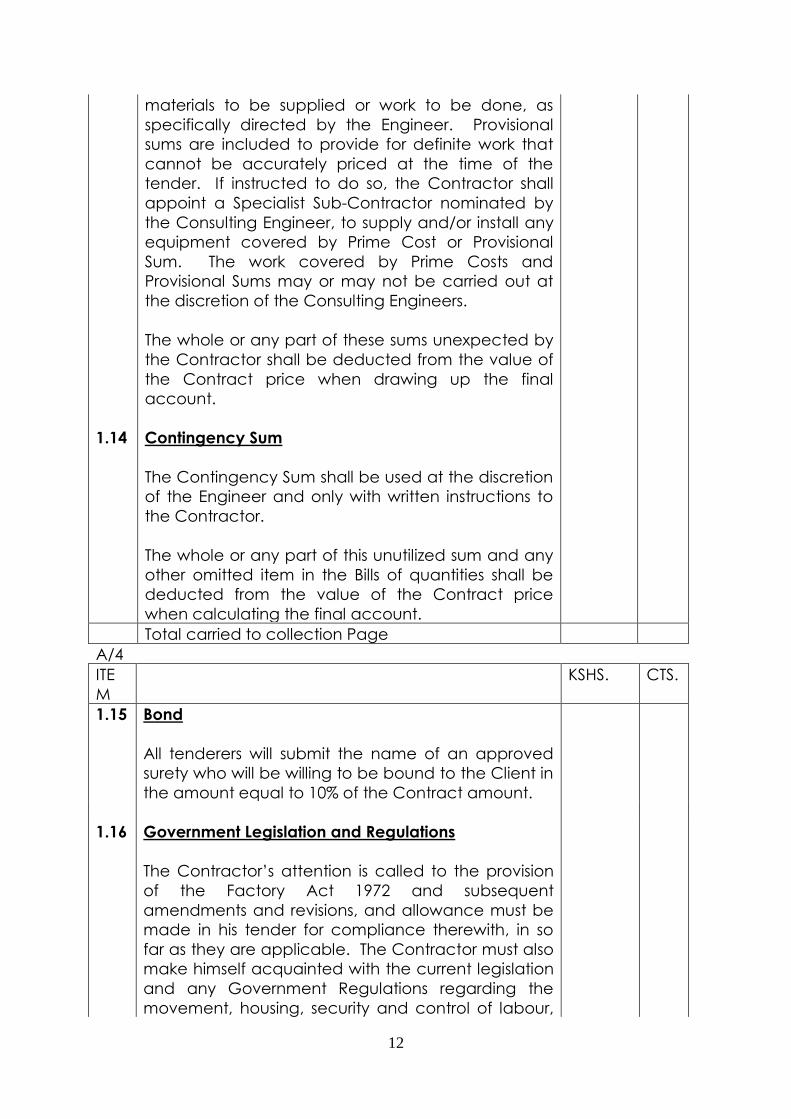
materials to be supplied or work to be done, as
specifically directed by the Engineer. Provisional
sums are included to provide for definite work that
cannot be accurately priced at the time of the
tender. If instructed to do so, the Contractor shall
appoint a Specialist Sub-Contractor nominated by
the Consulting Engineer, to supply and/or install any
equipment covered by Prime Cost or Provisional
Sum. The work covered by Prime Costs and
Provisional Sums may or may not be carried out at
the discretion of the Consulting Engineers.
The whole or any part of these sums unexpected by
the Contractor shall be deducted from the value of
the Contract price when drawing up the final
account.
1.14 Contingency Sum
The Contingency Sum shall be used at the discretion
of the Engineer and only with written instructions to
the Contractor.
The whole or any part of this unutilized sum and any
other omitted item in the Bills of quantities shall be
deducted from the value of the Contract price
when calculating the final account.
Total carried to collection Page
A/4
ITE
M
KSHS. CTS.
1.15
Bond
All tenderers will submit the name of an approved
surety who will be willing to be bound to the Client in
the amount equal to 10% of the Contract amount.
1.16 Government Legislation and Regulations
The Contractor’s attention is called to the provision
of the Factory Act 1972 and subsequent
amendments and revisions, and allowance must be
made in his tender for compliance therewith, in so
far as they are applicable. The Contractor must also
make himself acquainted with the current legislation
and any Government Regulations regarding the
movement, housing, security and control of labour,

13
labour camps, passes for transport, etc.
The Contractor shall allow for providing holiday and
transport for work people, and for complying with
Legislation Regulations and Union Agreements.
1.17 Import Duty and Value Added Tax
The Contractor shall be required to pay full Import
Duty and Value Added Tax on all items of
equipment, fittings and plant, whether imported or
locally manufactured items.
All rates entered in the Bills of Quantities shall exclude
V.A.T. There shall be a component of V.A.T on the
summary page.
1.18 Insurance Company Fees
Attention is drawn to the Tenderers to allow for all
necessary fees, where known, that may be payable
in respect of any fees imposed by Insurance
Companies or Statutory Authorities for testing or
inspection. No allowance shall be made to the
Contractor with respect to fees should these have
been omitted by the Tenderer due to his negligence
in this respect.
1.19 Provision of Services
(a) The Main-Contractor shall make available to
the Sub-Contractor the provision of water,
lighting and power. All those services utilized
shall be paid for by the Main-Contractor. The
Sub-Contractor shall however allow for
additional connections/extensions required
for his purposes.
(b) In the absence of a Main Contractor, the
Electrical Contractor shall make available all
the facilities necessary to complete the
installation. These include provision of
ladders, scaffolding, cable extensions etc. It
shall be deemed that the Contractor will
have catered for the cost of such facilities in
his tender.

14
Total carried to collection page
A/5
ITE
M
KSHS. CTS.
1.20 Storage of Materials on Site
The Contractor may be allocated areas for the
purpose of storing materials and equipment on site
when such areas are available. In such a case he
would be responsible for ensuring the given area is
waterproof. If such an area is not available, the
Contractor will be responsible for providing his own
sheds and lock-up facilities.
The Contractor shall when called upon by the Client
or Engineer move any part of his plant or materials
elsewhere not withstanding his having previously
obtained permission for it to be temporarily
accommodated at any location.
1.21 Suppliers
The Contractor shall submit the names of any
approved suppliers for the materials to be
incorporated, to the Engineer for approval. The
information regarding the names of supply will not
be changed without prior approval.
1.22 Samples and Materials Generally
The Contractor shall, when required, provide for
approval at no extra cost, samples of all materials to
be incorporated in the works. Such samples when
approved shall be retained by the Engineer and
shall form the standard for all such materials
incorporated.
No materials of any description shall be used or
delivered to site without prior sanction by the
Engineer, and any materials condemned as unfit for
use in the works, must be removed immediately from
the site without any recompense to the Contractor.
All materials for the permanent works shall be new
and shall, where no other specification is given, be
of first class quality and suitable for the purpose
intended.

15
Where trade names or manufacturer’s catalogue
numbers are mentioned the reference is intended as
a guide to the type of article or quality of material
required. The Contractor may use any article or
material equal in type or quality to those described
subject to prior approval by the Engineer. The
Contractor shall be responsible for proving
equivalence in quality.
1.23
Working Drawings
The Contractor shall prepare working drawings in
such details not only that the Contract Works can be
executed on site but also that the Engineer can
approve the Contractor’s proposals, detailed
designs and intentions in the execution of the
Contract Works.
1.24
Faulty Works
The whole of the works shall be carried out to the
satisfaction of the Engineer who shall have the right
to reject any materials or workmanship which is in his
opinion unsatisfactory. The Contractor shall replace
such materials or rectify such bad workmanship
forthwith, at his own expense.
1.25 Test Certificates
The Contractor shall provide the Engineer with three
copies of all test reports or certificates that are, or
may be, required by this Specification.
Total carried to collection page
A/6
ITEM KSHS. CTS.
1.26 Supervision
During the progress of the works, the Contractor shall
provide and keep constantly available for
consultation on site an experienced English-speaking
Supervisor and reasonable office facilities,
attendance, etc. for this supervisor. In addition
during the whole of the time works are under
construction, the Contractor shall maintain on site an
experienced foreman or charge hand and an
adequate number of fitters etc, for the work covered
by this staff shall not be reduced without the prior
written approval of the Engineer.

16
Any instructions given to the supervisor on site shall be
deemed to have been given to the Contractor.
One copy of this Specification and one copy of each
of the contract drawings (latest issue) must be
retained on site at all times, and be made available
for reference by the Engineer or Sub-Contractor.
1.27 Fair Wages
The Contractor shall comply in all respects with
Clause 30, “Wages and Conditions” contained in the
Agreement and Schedules of Conditions of Building
Contract (1972 edition).
1.28 Payments
Payments shall be made through certificates to the
Client. No payment will become due until materials
are delivered to the site. Payments shall be
implemented in phases with an earlier indication of
anticipated cash projection to enable the Client plan
a cash flow.
1.29 Final Account
On completion of the work the Contractor shall
agree with the Engineer the value of any variations
outstanding and as soon as possible thereafter submit
to the Architect and Engineer his final statement of
account showing the total sum claimed sub-divided
as follows:-
Statement A detailing the tender amounts less the
Prime Cost and Provisional Sums,
included therein.
Statement B detailing all the variations orders issued
on the Contract.
Statement C summarizing statement A and B and
giving the net grand total due to the
Contractor for execution of the Contract.
1.30 Damages for Delays
Liquidated and ascertained damages as stated in
the Contract Agreement shall be claimed against
the Contractor for any unauthorized delay in
completion. The Contractor shall be held liable for

17
the whole or a portion of these damages should he
cause delay in completion of the works.
1.31 Clearing of Site
The Contractor shall clear all his debris and surplus
rubbish material off the site. He shall, at his own
expense remove and clear away all plant,
equipment, rubbish and unused materials, and shall
leave the whole of the works in clean and tidy state,
to the satisfaction of the Engineer.
Total Carried to collection page
A/7
ITEM KSHS. CTS.
1.32 Guarantee
The whole of the Contract Works shall be guaranteed
for a period of six months from the date of the
Engineer’s certificate of completion and under such
guarantee the Contractor shall remedy at his own
expense all defects in materials, and apparatus due
to faulty design, construction or workmanship which
may develop in that period.
The Contractor shall also make good any damage
caused to other works, finishes, equipment etc., due
to above defects during this period.
This clause shall not in any way invalidate any
manufacturer’s guarantee on equipment which may
extend for periods longer than the Architect’s
Certificate of completion.
1.33 “As Installed” Drawings
At the completion of the Sub-Contract the
Contractor shall supply the Engineer with:
(i)1 set of transparent originals
(ii)3 sets of prints
Both shall show the complete installations and shall
include the location of all apparatus, conduit runs,
and ductwork.
1.34 Maintenance Manuals and Certificates of Guarantee
Two fully comprehensive maintenance and

18
operation instruction manuals shall be provided by
the Contractor including any manufacturer’s
certificate of guarantee. These documents shall be
handed to the Engineer before the final payment is
made.
1.35 Measured Work
All “Provisional” and other work liable to adjustment
or costing at “measured rates” under this contract or
subsequent additions or modifications, shall be left
uncovered for a reasonable time to allow the
necessary measurements to be taken by the
Engineer. Immediately the work is ready for
measurement, the Contractor shall give notice to the
Engineer.
1.36 Facilities for Inspection
The Engineer shall be allowed all facilities for
inspecting materials and workshop on the site during
the execution of the contract and a similar
reservation for inspection at the maker’s works shall
be included in all orders for specially manufactured
equipment issued by the Contractor. In such cases
notice shall be given to the Engineer that material
has been manufactured and is ready for inspection
and testing so that this may be carried out before the
material is packed for Shipment.
1.37 Setting Out
The Contractor shall set out the Works in accordance
with the dimensions and levels shown on the
drawings and shall be responsible for the correctness
of all dimensions and levels so set out by him and will
be required to amend all errors arising from
inaccurate setting out at his own cost and expenses.
In the event any error or discrepancy must be
reported by the Contractor to the Engineer for his
immediate consideration.
Total carried forward to collection page
A/8
ITEM KSHS CTS
1.38 1 Builder’s Work
All necessary chasing, cutting away and making
good will be done by the Main Contractor but the

19
Contractor shall mark out in advance and shall be
responsible for accuracy of sizes and position of all
holes and chases required.
1 Total carried forward to collection
page
A/9
ITEM DESCRIPTION KSHS. CTS.
PRELIMINARIES AND CONDITIONS OF CONTRACT
COLLECTION
1. Brought forward from Page No.A1
2. Brought forward from Page No.A2
3. Brought forward from Page No.A3
4. Brought forward from Page No.A4
5. Brought forward from Page No.A5
6. Brought forward from Page No.A6
7. Brought forward from Page No.A7
8. Brought forward from Page No.A8
9. Brought forward from Page No.A9
TOTAL CARRIED FORWARD TO SUMMARY PAGE
450,000
00
1.3 Format of tender response and other information for contractors
Proposals from Contractors shall be submitted in two distinct parts, namely
technical proposal and financial proposal and these shall be in two separate
sealed envelopes, both of which shall then be placed in a common sealed
envelope marked
“TENDER FOR ELECTRICAL POWER UPGRADE AT KENYA COMMERCIAL BANK’S
KENCOM HOUSE BUILDING NAIROBI”
The two separate inner envelopes shall be clearly marked “Technical
Proposal”, and “Financial Proposal”, respectively, and shall bear the name of
the Contractor.
The bid documents shall be addressed as below and dropped at the tender
box on 5th Floor, Kencom House, Wing B on 27th March 2015, 3.00 pm or
before the closing date.

20
Note: KCB shall not receive any tenders by facsimile or electronic mail courier
and / or post.
Head of Procurement
Kenya Commercial Bank
5th Floor Kencom House
P.O. Box 48400, 00100
Nairobi, Kenya
1.3.1 Proposal evaluation & information for Contractors
A two-stage procedure will be adopted by the Bank for evaluating the
proposals, with the technical evaluation of all proposals received in time
being completed prior to any financial proposal being evaluated. Proposals
will be evaluated based on the following general areas:
(a) Firm’s capacity and relevant experience
(b) Firm’s statutory and regulatory compliance
(c) The specific responses to requirements outlined in the tender
document
(d) Overall value proposition as outlined in the tender document
Contractors are requested to hold their proposals valid for ninety (90) days
from the closing date of submission. The Bank will make its best efforts to arrive
at a decision within this period.
Assuming that the Contract can be satisfactorily concluded the winning
bidder shall be expected to commence the assignment within two (2) weeks
after the final agreement is reached.
The Bank reserves the right to accept or to reject any bid, and to annul the
bidding process and reject all bids at any time prior to the award of the
contract, without thereby incurring any liability to any Contractor or any
obligation to inform the Contractor of the grounds for its action.
1.3.2 Documents Constituting the Tender
The Tender submitted by the Tenderer shall consist but not limited to the
following components:
1.3.2.1 Technical proposal
a) Copy of tender document, single line and layout diagrams
b) Technical schedules (section 8) duly filled and requested attachments
provided
c) Bidder’s details (Appendix E) dully filled and requested attachments
provided
d) Certificate of compliance (Appendix B) and letter to KCB on the
contractor’s letter head (Appendix C) duly filled and signed

21
e) Any information or other materials required to be completed and
submitted by Tenderers, as specified in the Tender Document
1.3.2.2 Financial proposal
a) Form of Tender (Appendix A) duly filled and signed
b) Priced Bill of Quantities (Appendix F) – initial every page
1.3.3 Cost of bidding
The Contractor shall bear all costs associated with the preparation and
submission of its bid, and the Bank will in no case be held responsible or liable
for those costs, regardless of the conduct or outcome of the bidding process.
1.3.4 Clarification of bidding document
All correspondence related to the contract shall be made in English. Any
clarification sought by the Contractor in respect of the project shall be
addressed in writing to the Head of Procurement at least five working (5)
days before the deadline for submission of bids.
The queries and replies thereto shall then be circulated in the form of an
addendum to all other prospective Contractors (without divulging the name
of the Contractor raising the queries), which shall be acknowledged in writing
by the prospective Contractors.
Enquiries for clarifications shall be sent by e-mail to [email protected]
1.3.5 Amendment of bidding document
At any time prior to the deadline for submission of bids, The Bank, for any
reason, whether at its own initiative or in response to a clarification requested
by a prospective Contractor, may modify the bidding document by
amendment.
All prospective Contractors that have received the bidding documents will
be notified of the amendment in writing, and it will be binding on them. It is
therefore important that Contractors give the correct details at the time of
collecting/receiving the bid document.
To allow prospective Contractors reasonable time to take any amendments
into account in preparing their bids, The Bank may at its sole discretion
extend the deadline for the submission of bids based on the nature of the
amendments.
1.3.6 Deadline for submission of bids
Bids shall be addressed to The Head of Procurement and sent for receipt on
or before Friday 27th March, 2015 3PM.
Bids received after the above-specified date and time shall not be
considered.
Any bid received by the Bank after this deadline will be rejected.

22
1.3.7 Cost structure and non-escalation
The Contractor shall, in their offer, detail the proposed costs.
No price escalation under this contract shall be allowed.
1.3.8 Taxes and incidental costs
The prices and rates in the financial offer will be deemed to be inclusive of all
taxes and any other incidental costs.
1.3.9 Responsiveness of proposals
The responsiveness of the proposals to the requirements of this tender will be
determined. A responsive proposal is deemed to contain all documents or
information specifically called for in this tender document. A bid determined
not responsive will be rejected by The Bank and may not subsequently be
made responsive by the Contractor by correction of the non-conforming
item(s).
1.3.10 Currency for pricing of tender
All bids in response to this tender shall be expressed in Kenya Shillings.
Expressions in other currencies shall not be permitted.
1.3.11 Correction of errors
Bids determined to be substantially responsive will be checked by The Bank
for any arithmetical errors and due diligence will be done to correct the errors
and final costs adjusted accordingly. If the Successful Bidder does not accept
the correction of the errors, its Bid will be rejected, and its Bid security may be
forfeited.
1.3.12 Evaluation and comparison of bids
Technical proposals will be evaluated prior to the evaluation of the financial
proposals. Financial proposals of firms whose technical proposals are found to
be non-qualifying in whatever respect may be returned unopened.
1.3.13 Clarification of bids
During evaluation of the Bids, The Bank, at its discretion, may ask the Bidder
for clarification of its Bid. The request for clarification and the response shall
be in writing, and no change in the prices or substance of the Bid shall be
sought, offered or permitted.
1.3.14 Confidentiality
The tender contains information proprietary to the Bank. The Bank requires the
recipients of this document to maintain its contents in the same confidence
as their own confidential information and refrain from reproducing it in whole
or in part without the written permission of The Bank

23
The information provided by the bidder/s will be held in confidence and will
be used for the sole purpose of evaluation of bids.
1.3.15 Scope of work
The project includes but not limited to the following key activities;
(a) Installation of an appropriate transformer to meet the present and
future load demands of the Bank and facilitate 11kv utility metering
(b) Installation of medium voltage protection circuit breaker
(c) Installation of a new low voltage distribution board to meet the
present and future load requirements of the Bank
(d) Provision for future installation of additional redundant transformer for
second line from Kenya Power.
(e) Provision of an automatic changeover in the new switchboard for the
existing generators
(f) Disconnection of existing standby generator connection from existing
switchboard and connection to the new switchboard
(g) Installation and commissioning of ventilation/ air condition systems at
the new and existing switch rooms and transformer rooms
(h) Load balancing and redistribution at the existing switchboard
(i) Partitioning of available space to accommodate 11kv KPLC metering,
RMU, medium voltage circuit breaker for the Bank and the new switch
room
(j) Construction of cable trenches to accommodate both Kenya Power
and the Bank’s cables
(k) Service/repair of existing switchboard and associated switchgear
(l) Making good the existing switch room cable trenches and floor
(m) Provision of any other service necessary to actualize the
project
The works shall be carried out in accordance with generally accepted
standards of professional practice, following recognized engineering
procedures and standards.
The contractors’ scope of work is to cover all activities necessary to
accomplish the stated works, while adhering to best practices of the
profession, whether or not a specific activity is cited in this tender
2 COMMERCIAL TERMS AND CONDITIONS
2.1 Bank reserves the right to the following
(a) Reject any or all proposals received in response to the tender without
giving any reason whatsoever
(b) Waive or Change any formalities, irregularities, or inconsistencies in
proposal format delivery
(c) Extend the time for submission of proposal.
(d) Modify the tender document, by an amendment that would be
displayed on Bank’s Website

24
(e) Select the next most responsive Contractor if negotiations with the
Contractor of choice fail to result in an agreement within a specified
period.
(f) To independently ascertain information from other institutions to which
Contractor has already extended services for similar assignment.
(g) Apply whatever evaluation criteria deemed appropriate for evaluation
of Technical Bids.
(h) Terminate the services if the assignment is not proceeding in
accordance with the terms of contract or undue delay is taking place
in execution of the assignment.
(i) Modify the time period for completion of assignment during the
execution of assignment.
2.2 Force Majeure
The Contractor shall not be liable for forfeiture of its performance security,
liquidated damages, or termination for default if and to the extent that it’s
delay in performance or other failure to perform its obligations under the
Contract is the result of an event of Force Majeure.
For purposes of this clause, “Force Majeure” means an event beyond the
control of the Bidder and not involving the Service Provider’s fault or
negligence and not foreseeable. Such events may include, but are not
restricted to, acts of the Bank in its sovereign capacity, wars or revolutions,
fires, floods, epidemics, quarantine restrictions, and freight embargoes.
If a Force Majeure situation arises, the Bidder shall promptly notify the Bank in
writing of such condition and the cause thereof. Unless otherwise directed by
the Bank in writing, the Bidder shall continue to perform its obligations under
the Contract as far as is reasonably practical, and shall seek all reasonable
alternative means for performance not prevented by the Force Majeure
event.
2.3 Termination for Insolvency
The Bank may, at any time, terminate the Contract by giving written notice to
the Bidder if the Bidder becomes Bankrupt or otherwise insolvent. In this
event, termination will be without compensation to the Contractor, provided
that such termination will not prejudice or affect any right of action or
remedy, which has accrued or will accrue thereafter to The Bank.
2.4 Termination for Convenience
The Bank, by written notice sent to the Contractor, may terminate the
Contract, in whole or in part, at any time for its convenience. The notice of
termination shall specify that termination is for the Bank’s convenience, the
extent to which performance of the Bidder under the Contract is terminated,
and the date upon which such termination becomes effective.
2.5 Performance Guarantee
The Bidder selected for the assignment should furnish a performance
guarantee in favor of Kenya Commercial Bank, for 10% of the value of
accepted tender value valid for a period of 12 months ( from the date of

25
awarding contract) from a recognized bank other than Kenya Commercial
Bank. The performance guarantee shall be submitted within a period of 15
days from the date of contract award.
2.6 Time of completion & penalty clause
All works shall be completed within the agreed time schedule. If the
Contractor fails to complete the works within the stipulated time frame, the
Contractor shall be liable to pay The Bank pre estimated damages at the
rate of half percent of the final contract price for each week of delay or part
thereof subject to a maximum of 10% of the final contract value.
2.7 Injury to persons, property & Owner’s Indemnity
The Contractor shall be liable for and shall indemnify The Bank against any
liability loss, claim or proceedings whosoever arising under any statute or
common law in respect of personal injury to or the death of any person
whomsoever arising out of or in the course of carrying out the works unless
due to any act or neglect of The Bank or of any person for whom The Bank is
responsible.
Except of such loss or damage as is at the risk of The Bank under the Contract
the Contractor shall be liable for and shall indemnify The Bank against any
expense, liability, loss claim or proceedings in respect of any injury or damage
whatsoever to any property real or personal in so far as such injury or
damage arise out of or in the course of or by reason of carrying out the works
and provided always that the same is due to any negligence omission or
default of the Contractor his servants or agents or of any sub-contractor his
servants or agents.
2.8 Accidents
The Contractor shall within 24 hours of the occurrence of any accident at or
about the site or in connection with the execution of the work report such
accident to The Bank’s representative. The Contractor shall also report such
accident to the Competent Authority whenever such report is required by
law.
2.9 Labour laws
The Contractor shall comply with the provision of all Labour Laws of Kenya
and any other Act or enactment relating thereto and rules framed there
under from time to time.
2.10 Cost of tests
The cost of arranging/undertaking any test, as directed by The Bank shall be
borne by the Contractor.
2.11 Statutory authority obligations, notices, fees charges
The Contractor shall comply with and give all notices required by any act,
any instrument, rule or order made under any Act, or any regulation or by-law
of any County/Local authority or of any regulation of any agency which has
any jurisdiction with regard to the works or with whose systems the same are
or will be connected (all requirements to be so complied with being referred
to in these conditions as the statutory requirements).

26
If the Contractor shall find any divergence between the statutory
requirements and all or any of the contract documents or any variation
instruction issued in accordance with these conditions, shall immediately give
to The Bank’s Representative a written notice specifying the divergence.
If the Contractor gives notice or if The Bank shall otherwise discover or receive
notice of a divergence between the statutory requirements and all or any of
the contract documents or any variation, instructions issued in accordance
with these conditions The Bank shall within 7 days, of discovery or on receipt
of a notice, issue instructions in relation to the divergence. If and in so far as
the instructions require the works to be varied, they shall be deemed to be
Bank’s instructions issued in accordance with these conditions.
2.12 Work to be done to the satisfaction of The Bank
The Contractor shall execute, complete and maintain the work in strict
adherence with the contract to the satisfaction of The Bank and shall comply
with the specifications and adhere strictly to The Bank’s instructions and
directions on any matter (whether mentioned in the contract or not)
concerning the work. The Contractor shall take instructions and directions
from The Bank’s representative.
3 GENERAL SPECIFICATIONS
3.1 Extent of Electrical Installations
The tenderer shall include in his tender, prices for the design of new
installations, manufacture, inspection, testing, packing, shipment,
insurance, shipping, customs duties, taxes, delivery to site, unloading
and all other charges. The tenderer shall also include for complete
erection, tests on completion, setting to work, finishing and painting
and maintenance of all items of plant and equipment described or
implied within these Technical Specifications and shown on the
relevant drawings to the satisfaction of the Engineer.
The electrical services within the buildings shall be complete in all
respects as specified herein, and shall include all items of equipment,
materials, accessories, fittings, supports, etc. necessary whether such
items are specifically referred to in the Contract or not. The tenderer
shall be deemed to have included in his tender price all items
necessary such that the installations are complete in all respects and
left in good working order.
If awarded the Contract, the Contractor shall be expected to provide
fully detailed drawings of the entire installation together with layouts of
all civil and building works etc. required to accommodate / house the
plant and equipment, these layout drawings and details being related
to the existing layouts as may be necessary. The drawings shall be
submitted for approval within three weeks of the award of the
Contract such that the Engineer can be made aware of all
requirements. It shall be deemed to be the responsibility of the

27
Contractor to ensure all civil and builder's works required for this
Contract are prepared and / or provided to suit the program of this
Contract. No claims will be entertained.
All proposed new layouts and structures shall be subject to the full
approval of the Engineer and the Employer.
3.2 Program for Electrical Engineering Installations
The tenderer shall provide within a stipulated period of acceptance of
this tender and award of Contract, a complete program for the
electrical engineering installations to be executed indicating the
anticipated commencement and completion dates of the following
activities:
(i) Submission of working drawings for approval;
(ii) Placing of orders with other specialists for plant and equipment
to be incorporated in the works;
(iii) Receipt by the Contractor from other specialists of plant to be
incorporated in the works;
(iv) Manufacture by the Contractor of plant to be incorporated in the
works;
(v) Inspection and testing of installation by the Contractor to
Engineer’s satisfaction;
(vi) Shipment of the plant from country of manufacture;
(vii) Delivery of the plant and equipment to site;
(viii) Erection on site, details for all activities;
(ix) Kenya Power installations;
(x) Testing and Commissioning on Project Completion.
Operations shall be commenced when instructed and shall be carried
forward to completion with the greatest possible expediency, to the
satisfaction of the Engineer, in accordance with the Program. The
Contractor’s program shall be agreed with the Engineer and shall
adhere fully to the requirements and timing of the agreed timelines by
the client.
3.3 Drawings accompanying the Tender Documents
The Electrical Drawings indicate generally the arrangement of the
installations and are for assistance in tendering only. The position of
equipment and apparatus shown thereon are approximate only, the
exact positions, together with the actual runs of ductwork, trunking and
conduit etc., will be agreed upon with the Engineer, Architect and the
Employer prior to commencement of work. It shall be deemed that the
prices entered by the Contractor include for the repositioning, of the
various services, to meet the above requirements. No claims will be
entertained.
The Contractor shall satisfy himself as to the correctness of all Drawings
and measurements particularly the dimensions of the electrical

28
installations. If the Contractor finds any discrepancy in the Drawings or
between the Drawings and the Technical Specifications or between the
electrical installations and the Drawings, he shall immediately refer the
same to the Engineer who will make a ruling on the discrepancy. Figured
dimensions shall be taken in preference to the scale mentioned on or
attached to any Drawings. Details shown on Drawings shall be read in
conjunction with items included in the Technical Specifications.
The Engineer will furnish the Contractor within a reasonable time after the
receipt by the Engineer of a written request for the same, any details of
which, in the opinion of the Engineer are necessary for the execution of
any part of the works. Such a request to be made only within a
reasonable time prior to the execution of such work in order to fulfil the
Contract. One copy of the Drawings, details and Technical Specifications
shall be kept on the site until the completion of the Contract and the
Engineer shall at all reasonable times have access to the same. The
Contractor shall return all copies of Drawings and other relevant details
to the Engineer on the completion of the Contract.
Additional Drawings will be issued by the Contractor to the Engineer to
suit the design requirements of the works. These Drawings being issued
either during or after the tender period as may be required or necessary.
These Drawings will supplement the details contained within the
Technical Specifications and Bills of Quantities and the Tenderer shall be
deemed to have taken these into account in his pricing. Where the
Contractor can demonstrate that the Drawings relate to new approved
or additional items these new or additional items shall be priced to
approval in accordance with the Contract rates and prices.
3.4 Contract Working Drawings
The Contractor shall prepare fully detailed Working Drawings for all items
of plant, equipment and accessories required for installation under this
section of the Contract. Two copies of each Drawing shall be
forwarded to the Engineer for approval and or comments. One copy
will be returned stamped "approved" or "not-approved". Where
Drawings require further information and / or modifications to meet the
comments made by the Engineer they shall be re-submitted, again in
duplicate, for approval.
When Drawings have been approved two further copies shall be
forwarded to the Engineer, together with copies to the Employer.
Drawings, and, where relevant, calculations in respect of the following
shall be prepared by the Contractor and submitted to the Engineer for
his approval commencing within five (5) days from acceptance of the
tender.
All drawings shall be to scale and fully detailed with all the important
dimensions shown and the construction of key components indicated.

29
During progress of the building works, the Contractor shall make all
necessary checks on site to ascertain that the various services can be
installed as specified and shown on the approved Drawings.
Where such works cannot be so installed, this must be immediately
brought to the notice of the Engineer and employer prior to the progress
of such works.
The Engineer, in conjunction with the Employer, will check and return the
Drawings submitted for approval within a reasonable period, but in any
case not exceeding five (5) days from receipt of the Drawings.
The layouts of plant and equipment are for general guidance only.
The Contractor shall assess the requirements and prepare a plant
layout for approval within seven (7) days, the required liaison being
maintained with other specialists, such that an agreed layout is
submitted for approval.
3.5 Record Drawings (“As Installed Drawings”)
As soon as the works are complete and all tests satisfactorily carried
out, the Contractor shall hand to the Engineer two sets of Record
Drawings, together with one set of negatives of the same, showing the
works as finally installed. These Drawings shall be prepared on
approved transparent plastic material in black ink or as approved by
the Engineer. The certificate, of making good defects, will not be issued
until this condition has been complied with. Record Drawings are in
addition to detailed Working Drawings and shall show all cable routes,
circuits, trunking, conduits, plant, trenches, ductwork and ducts etc., as
finally installed.
The Engineer will provide the Contractor with a set of Contract
Drawings (in addition to the two sets provided for the Contractor's site
and office use), which shall be maintained by the Contractor's
representative on site and which shall be used for recording of
Contract variations as they occur. This set of Drawings shall be
available for the Engineer's inspection on site, and shall be kept up to
date.
The cost of the preparation and submission of the above Contract and
Record Drawings shall be deemed to be included within the
Contractor's prices.
3.6 Data Schedule
As part of the submittals the Contractor will be required to submit data
schedule and technical literature for the materials and equipment to
be supplied under this contract. These shall be submitted to the
Engineer for approval before delivery of similar materials to site. It shall
be deemed to be the responsibility of the contractor for any materials
found on site without Engineer’s prior knowledge.

30
3.7 Maintenance Manuals
At the start of the defects liability period, the Contractor shall hand
over to the Engineer, four sets of maintenance and operations manuals
for each plant and equipment installed. These manuals shall be in
English and shall be fully illustrated.
3.8 Builder's Work and Civil Works
Builder's Work and Civil Works that are incidental to this section of the
Contract such as cutting of holes in walls and floors, provisions of
foundations for the plant and machinery, shall be the responsibility of the
Contractor. The Contractor shall be fully responsible for the preparation
of all such details that relate to such works, the details being subject to
approval by the Engineer prior to submission to the Main Contractor for
action. Other items such as fixing of brackets, cables and ductwork and
trenching, making good etc. shall be carried out by the Contractor to
suit the installation of all the services. In the absence of the main
contractor, the contractor shall seek the services of qualified
subcontractor for the civil/structural work.
It is the Contractor's sole responsibility to ensure that all holes and chases
are in the required position and that any additional ducts, holes and
chases necessary for erection of the installations in situ concrete walls,
floor slabs etc., are included in the early stages of construction as
appropriate.
The Contractor shall furnish the Engineer with all the necessary
information including position of foundations, brackets and fixings and
shall ensure that such works are performed in accordance with
available information.
The Contractor shall include in his tender all supports, fixings, plugging of
holes in walls, ceilings and floors to facilitate the fixing of the pipe work,
accessories, and all other portions of the plumbing, drainage and
firefighting installations. Any purpose-made fixing brackets shall also be
provided and installed by the Contractor, including escutcheon plates
and the like.
The Contractor shall supply and install approved pipe work support
brackets and hangers. It shall be deemed that prices include for any
special requirements and that the Contractor has visited the site during
the tender period to ascertain all details.
The Contractor shall pay particular attention to the fixing and alignment
of items. All items shall be installed square, true and perpendicular to
floors i.e. as shown on Drawings and as may be required at site to the
Engineers approval.
The contractor is required to engage a qualified Civil/Structural
contractor to do all the civil/structural works. A valid proof of
Registration by NCA will be mandatory.

31
3.9 Commissioning of the Electrical Installation
The Contractor shall instruct the Employer’s Maintenance Engineer or
his representative on the operation and maintenance of the various
components forming the electrical installation and shall provide
drawings, diagrams and manuals to ensure the Maintenance Engineer
or his representative is completely conversant with such installations.
The Contractor shall ensure that the services installations are left in
complete safe working order and operating to the satisfaction of the
Engineer.
3.10 Regulations and Standards
The Installations must be carried out strictly in accordance with the
following documents: -
Electrical Services:
(i) The current edition of the IEE Wiring Regulations , BS 7671;
(ii) Relevant International Standards;
(iii) Current Regulations and by-laws of Kenya Power (Kenya side);
(iv) Regulations and by-laws of the Ministry of Energy;
(v) Kenya Local Authority By-Laws;
(vi) Current Regulations of Telkom Kenya (Kenya side);
(vii) By-laws of the Energy Regulatory Commission (ERC);
(viii) Any other duly constituted authorities regulations having jurisdiction
over the Works;
(ix) Water Supply and Sewerage Authority’s Regulations;
(x) The Specification and accompanying documentation and
Drawings;
(xi) The Working Drawings produced by the Contractor and approved
by the Engineer.
The Contractor shall undertake all modifications demanded by the
authorities in order to comply with the regulations, and produce all
certificates, if any, for the authorities at no extra charge.
3.11 Quality of Materials
All materials, equipment, plants, fittings and accessories are to be new
and in accordance with the requirements of the current rules and
regulations where such exist, and with the relevant international
standards.
Uniformity of type and manufacture of equipment, plants, fittings and
accessories is to be as far as practicable preserved throughout the
whole Works.
Wherever the term 'similar to' is used in these Technical Specifications in
reference to any item, the word will be understood to mean type and
quality of the equipment and not preference.

32
Where particular manufacturers only are specified herein no alternative
makes will be considered without good reasons.
All materials shall be of good quality, suitable for the purpose specified,
and to the approval of the Engineer.
3.12 Workmanship
The tenderer shall take into consideration, when pricing his tender, that
there will be other specialists working alongside him. Any disruptions to
the existing services must therefore be kept to a minimum, and in this
respect the Contractor shall include in his prices for carrying out Works
outside normal working hours as may be directed by the Engineer. No
claim will be entertained where abnormal working hours are required
to meet this requirement and completion of the works within the
specified Contract period.
The Contractor shall be fully responsible for co-ordination of installation
of all services. For all services involving ducted wiring, such wiring shall
be capable of future addition or maintenance.
The Contractor shall be deemed to have included in his tender prices for
relocating equipment, plants, switches, terminal points, ductwork, outlets
and fixtures in positions and / or locations at least one meter in any
direction from the positions indicated on the Drawings. Within these
limits no variations in the Contract sum will be made unless the work has
already been executed in accordance with previously approved
Working Drawings.
Only qualified and certified persons shall be allowed to carry out
installation work. The Works shall be performed in a neat and
workmanlike manner.
The Contractor shall take every precaution to avoid damage to the
existing property including cars, driveways, cables, drains and other
services, and he will be held responsible for and shall make good all
such damage at his own expense to the satisfaction of the Engineer.
The Contractor will be responsible for the exact runs and placing of pipe
work, conduit, boxes, ductwork and accessories that are to be cast in
concrete, ceilings, floors, walls, columns and beams, and for the proper
fixing of the pipe work and accessories to the shuttering and the steel
reinforcement work, including raising of the slab with mass concrete,
walling etc.
Where ductwork is to be concealed, the pipes etc. shall be in an exact
position relative to the finished floor levels or such other finishes as may
be applied to enable adequate cover to be applied.
Where services are run above the false ceilings the Contractor shall
ensure that access to all services is readily available such that future
maintenance can be carried out without difficulty. Full details shall be

33
included on the Working Drawings such that the Engineer can give
consideration to the Contractor's proposals.
3.13 Setting out of work
The Contractor will be responsible for laying out his work and shall
obtain all the necessary information as may be required to carry out
the work. Such information shall be obtained sufficiently in advance to
avoid any possibility of delay to the Works as a whole.
The Contractor shall be fully responsible, and shall seek, the details of all
work being carried out by the various trades on Site, particularly where
such trades may interfere with each other, or where co-ordination is
necessary. No claims for extra costs will be entertained arising from
omissions, oversight, or neglect in this regard.
In advance of the delivery of the plant and equipment, the Contractor
shall arrange for the supply of all-necessary foundation bolts, templates,
nuts, plates, sleeves, anchorages, etc., as required and as may be
directed by the Engineer.
3.14 Erection and checking of work
The Contractor shall provide, and be solely responsible for, all skilled
and unskilled labour, tools, lifting tackle and other equipment required
for handling of plant and equipment when transporting to Site, within
the Site and during erection.
All erection works shall be subject to approval by the Engineer.
All parts shall pass such tests as required by the Engineer to prove
compliance with the Contract irrespective of any tests which may
already have been carried out at the Manufacturer's Works. In
particular all electrical pressure tests made at the Manufacturer's Works
shall be repeated at voltages approved by the Engineer.
The Contractor shall supply and install all supports, fixings, brackets and
similar items as may be necessary for the completion of the installation
of the services as specified and as shown on the Drawings.
3.15 Site performance and acceptance tests
The Contractor shall give notice of the date of the specified tests to be
performed on completion of installation. The notice shall be made in
writing to the Engineer at least five days to the date of the specified
tests. Unless otherwise agreed the tests shall take place within seven
days of the stated date or on such day or days as the Engineer shall in
writing notify the Contractor in writing. The tests shall be carried out
under normal working conditions to the satisfaction of the Engineer and
shall extend over such continuous periods as he may direct.
All skilled labour, supervision, apparatus, fuel and instruments required for
carrying out the tests will be the responsibility and at the expense of the

34
Contractor. The accuracy of the instruments shall be demonstrated if
required. The Contractor shall ensure that test instruments are in good
working condition and have been calibrated by an authorised agent.
If any part of the plant or equipment fails to pass the specified tests,
further tests of the said part shall, if required by the Engineer, be
repeated. The Contractor shall, without delay, put in hand such
modifications as found necessary so as to meet the requirements of the
Contract and any expense which the Client may have incurred by
reason of such further tests shall be deducted from the Contractor’s
Contract price.
Each completed system within the installation shall be tested as a
whole under operating conditions to ensure that each component
functions correctly in conjunction with the rest of the system.
3.16 Test records
The Contractor shall make the necessary records of all the tests carried
out, and when the tests have been successfully completed he shall
provide the Engineer with test records and reports in a format to be
agreed.
3.17 Dust, insect and vermin proofing
All equipment, likely to be affected by ingress of dust, shall be effectively
dust proofed and vermin proofed where no protection is afforded in its
normal manufactured form. All materials used shall be in general
resistant to attack by insects, micro-organisms or other fauna or flora.
Materials used for such protection shall be to the approval of the Client
and Engineer.
3.18 Painting and finishing
All mechanical and electrical plant and equipment installed under this
Contract shall be painted or otherwise finished to approval in
accordance with appropriate international code for standard colours
to be furnished by the Contractor prior to the shipment or manufacture
of the plant or equipment including all pipe work, ductwork, etc. Such
finish shall be entirely compatible with the conditions of heat, humidity,
exposure to the weather, and other relevant factors arising from the
materials, location and condition of operation of the equipment.
Paintwork will be measured in the builder's work in connection with the
Engineering Element. Any additional work will be measured in
accordance with the conditions of the Contract.
The Engineer may request samples of paint finishes, the cost of which
shall be deemed to have been included within the tendered prices for
all works.
All final painting of plants, equipment, fixtures, and accessories shall be
carried out by the Contractor, except where it is the usual practice of

35
the manufacturer of items of plant and equipment to apply a high
standard of protective finishing paintwork in the shop before despatch.
This will be acceptable provided the Contractor at his own costs makes
good any damage to paintwork, occurring in shipment, transportation
and installation.
The interiors of electrical switchboards control panels, and similar items,
shall be finished in an approved enamel colour and shall comply with
the appropriate international standards for enamel finish which shall be
furnished by the Contractor prior to shipment or manufacture of the
plant or equipment. The exteriors of such panels and enclosures shall
be of international standards specification colour as specified by the
Engineer.
3.19 Labels
All items of electrical plant, equipment, Sub-main distribution boards,
etc. shall be neatly and clearly labelled externally with identification
marks corresponding with those on Drawings or in Technical
Specifications. Final details shall be agreed upon by the Contractor
and the Engineer.
Identification labels shall be of laminated plastic material engraved,
white on black or white on blue, with no less than 6mm "Lino" style letters
and shall be fixed on or adjacent to all items by means of at least two
brass screws or to the approval of the Engineer. Self-adhesive labels shall
not be permitted.
All main switches, circuit breakers, isolators, valves, motors, switch-fuse,
consumer service units, and distribution boards etc. shall be neatly and
clearly labelled externally with identification marks corresponding with
those on the Drawings or Technical Specifications. Final details shall be
agreed upon by the Contractor and the Engineer. All labels / plates
shall be in English.
3.20 Specialist manufacturers
Where specialists are not nominated by the Employer, the Contractor
shall appoint specialist manufacturers and suitable specialists for any
sections of the Works described herein in which he is not himself an
experienced, recognized and approved specialist.
The tenderer shall, on submission of his tender, indicate the names of all
proposed specialist manufacturers and specialists, together with the
precise sections of the Works for which each will be responsible. The
Contractor may be required to seek alternative manufacturers or
Contractors or to accept specialists nominated by the Employer; it shall
be deemed that the prices entered in the tender include for this
requirement. For plant and equipment supplied by suppliers other than
the Contractor, the Contractor will be required to furnish an agreement
between himself and the supplier stating that he is authorised by the

36
supplier to deal in the plant and equipment and that he is authorised
to stock the necessary spare parts or that the Employer will be
authorised to revert to the supplier in the event of breakdown of the
plant or equipment.
The Contractor shall allow in his prices for phasing his work to meet the
requirements of the other specialists, and for varying his program or
otherwise, to comply with the erection program of such specialist. No
additional costs will be allowed to the Contractor for any disruptions to
his program, or otherwise, in his compliance with the above
requirements.
3.21 Interference with the existing Works
The Contractor shall not interfere in any way with any existing works
whether the property of the Employer or of a third party and whether
the position of such works is indicated to the Contractor by the
Engineer or not. The exception being where such interference are
specifically described as part of the Works either in the Contract or in
any form of instruction from the Engineer.
3.22 Protection of Works
The Contractor shall carefully protect from injury by weather all Work
and materials which may be affected thereby and allow in his prices
for all dams, pumping, shoring, temporary drains, sumps etc. necessary
for the purpose. The Contractor shall clear away and make good at his
own cost to the satisfaction of the Engineer all damage caused
thereby.
3.23 Sundries
The necessary holding down bolts, supporting brackets and templates,
guards and screens, locks, piping, conduits, lamps and other requisite
sundries whether specified in detail or not shall be provided, under the
Contract and it shall be deemed that the Contractor's prices, rates and
the like include for all such items.
3.24 Schedules of technical data
Where included in the Tender Documents, all tenderers shall complete
Schedules of technical data; otherwise the Tender may not receive full
consideration, and will be liable to rejection.
3.25 Copies of orders
Copies of all orders for major items of plant, equipment and materials
places with suppliers shall be provided in triplicate to the Engineer.
3.26 Inspection and tests at Manufacturer's Works
The Engineer, and his duly authorised representative, shall have at all
reasonable times access to the Contractor's premises to inspect and
examine the materials and workmanship of the mechanical and

37
electrical plant and equipment during its manufacture there. If part of
the plant and equipment is being manufactured on other premises, the
Contractor shall obtain for the Engineer and for his duly authorised
representative permission to inspect as if the plant and equipment was
manufactured on the Contractor's own premises. Such inspection,
examination or testing, if made, shall not relieve the Contractor from
any obligation under the Contract.
Where the plant and equipment is a composite unit of several
individual pieces manufactured in different places, it shall be
assembled and tested as one complete working unit, at the Maker's
works, to the relevant International Standards where applicable.
4 TECHNICAL SPECIFICATIONS FOR 11KV METAL CLAD
PROTECTION AND METERINGSWITCHGEAR PANEL
This specification has been prepared by Aberdare Engineering Ltd and
it lays down requirements for 11kV metal clad switchgear panels. It is
intended for use by KCB in purchasing the equipment.
4.1 General specifications
4.1.1 Scope
This specification covers the design and engineering, manufacture,
testing at the manufacturer’s factory, painting, packing for transport,
insuring, shipping, and delivering to the port of Kenya, landing, customs
clearing, transporting and delivery to KCB stores of 11kV Indoor Metal
Protection and Metering Switchgear Panels.
Subsequent paragraphs will give details descriptions and requirements
for the switchgear panels, including circuit breakers, current
transformers, voltage transformers, protection relays, metering,
measuring, indicating control devices and other equipment/device,
specified herein.
4.1.2 Standards
Rating characteristics, tests and test procedures, etc. for the 11Kv metal
clad switchgear panels and all the protection relays, measuring
indicating instruments and the control and monitoring devices and
accessories, including current transformers and voltage transformers
shall comply with the provisions and requirements of standards of the
international electro-technical commission (IEC), and also relevant ANSI
standards where specified.
The latest revision or edition in effect at the time of bid invitation shall
apply. Where references are given to numbers in the old numbering
scheme from IEC it shall be taken to be the equivalent number in the
new five-digit number scheme. The bidder shall specifically state the
precise standard, complete with identification number, to which the

38
various equipment and materials are manufactured and tested. The bid
document may not contain a full list of standards to be used, as they
referred to where useful clarification of text.
4.1.3 Unit of measurement and language
In all correspondence, in all technical schedules and on all drawings
prepared by the manufacturer, the metric units of measurements shall
be used. On drawings or printed pamphlets where other units have
been used, the equivalent metric measurements shall be added. All
documents, correspondence, drawings, operating and maintenance
instructions/manuals and nameplate details of the equipment shall be
in English language.
4.1.4 Service conditions
From the geographical condition, the area where the switchgear
panel shall be installed is categorized in to the tropical climate zone. In
choosing material and their finishes, due regard shall be given to the
humid tropical conditions under which the switchgear panels shall be
called upon to work. The manufacturer of the switchgear panel shall
submit details of his usual practice of tropicalization which have been
proven satisfactory for application to the switchgear panels and
associated equipment’s to prevent rusting and ageing in the tropical
climate zone. The applicable standards of tropicalization shall be
listed.
4.1.4.1 Climate Conditions
Unless otherwise specifically stated in particular technical specifications
any equipment’s or component or assembly shall be designed for the
following service conditions:
Parameter Max Min
Ambient air temperatures
Outdoor +40ºC -1ºC
Indoor +40ºC -1ºC
24 hour average maximum +30ºC -1ºC
Relative humidity 90-100%
Height above sea level 2200m
EMC Class (IEC 61000) Industrial environments
Seismic coefficient 1.5
Rainfall conditions
Average 800-1700mm/year
Maximum 160mm in 24hrs
Annual mean isokeraunic level Max 180 thunderstorm days
Pollution (IEC 60815) Heavy : class II
Creepage 25 mm/kV

39
4.1.4.2 Switchgear room temperatures
The switchgear panel shall be installed in a room without air
conditioning but with ventilation to allow natural cooling. Therefore all
the protection and control devices employed shall be capable of
operating in this environment without failure for their designed life time.
Particularly the power supply modules of the protection and control
devices shall be designed for minimum heat generation and effective
heat dissipation to ensure that the temperatures of these devices
enclosed in the relay panels at the above listed ambient temperatures
shall not exceed the maximum operating temperatures of the device.
4.1.4.3 Tropicalization
All equipment must be designed for operations in the severe tropic
climate conditions and fully comply with climatic aging tests as per IEC
60932-class 2.
In choosing materials their finishes, due regard shall be given to the
humid tropical conditions under which the switchgear will be called
upon to work. The manufacturer shall submit details of his usual
practice which have proven satisfactory for application to the parts of
the switchgear panels, which may be affected by tropical conditions.
4.1.5 Metals
Iron and steel are generally to be painted or galvanized as
appropriate. Indoor parts may alternatively have chromium or
copper-nickel plates or other approved protective finish. Small iron and
steel parts (other than trustless steel) of all instruments and electrical
equipment, the cores of electromagnets and the metal parts of relays
and mechanism shall be treated in an appropriate manner to prevent
rusting.
4.1.6 Screws, Nuts, springs, etc.
The use of iron and steel shall be avoided in instruments relays wherever
possible. Steel screw shall be Zinc, Cadmium or Chromium plated or
where plating is not possible owing to tolerance limitations, shall be of
corrosion resisting steel. Instrument screws (except those forming part of
magnetic circuit) shall be of brass or bronze. Spring shall be of non –
rusting materials e.g. phosphor-bronze or nickel silver, as far as possible
4.1.7 Rubbers
Neoprene and similar synthetic compounds, not subject to
deterioration due to the climatic conditions, shall be used for gaskets,
sealing rings, diaphragms, etc.

40
4.2 Working stress and equipment/apparatus design
4.2.1 General
The design, dimensions and materials of all parts shall be such that
they will not suffer damage under the most adverse conditions for
result in deflections and vibrations, which might adversely affect the
operation of the equipment. Mechanisms shall be constructed to
avoid sticking due to rust or corrosion.
The equipment and apparatus shall be designed and manufactured
in the best and most substantial and workmanlike manner with
materials best suited to their respective purpose and generally in
accordance with up-to-date recognized standards of good practice.
The equipment shall be designed to cope with 0.2g horizontal
acceleration of seismology on the center of gravity.
Whenever possible, all similar parts, including spares parts, shall be
made interchangeable. Such parts shall be of the same materials and
workmanship and shall be constructed to such tolerances as to
enable substitution or replacement by spare parts easily and quickly.
All equipment shall be designed to minimize the risk of fire and
consequential damage, to prevent ingress of vermin and dust and
accidental contact with electrically energized or moving parts. The
switchgear panels shall be capable of continuous operation with
minimum attention and maintenance in the exceptionally severe
conditions; likely to be obtained in a tropical climate and where the
switchgear is called upon to frequency interrupt fault current on the
system and also where the duty of operation is high.
4.2.2 Strength and quality
All steel casting and welding shall be stress –relieved by heat treatment
before machining, and castings shall be stress-relieve again after repair
by welding.
Liberal factors of safety shall be used throughout, especially in the
design of all parts subjects to alternating stresses or shocks.
4.2.3 Design data low voltage equipment
Low voltage equipment and installation shall be in accordance with
EMC directives. The rating and design criteria for low voltage
equipment shall be as follows:
4.2.3.1 AC Supply Rating system
Rated voltage between phase 415 V AC
Connection type 3ph 4wire
Rated voltage between phase to earth 240 V AC
Grounding system PME
Frequency 50 HZ

41
The AC supply shall be used for power circuit and lighting, indicating,
motors controls and similar small power circuits.
Unless otherwise specified, the equipment provided under this tender is
to be capable of reliable operation at voltage as low as 85% of the
rated voltage, and to withstand continuously up to 110% supply
voltage above the rated value of 240 or 415 AC.
4.2.3.2 DC Auxiliary Supply Rating
Equipment /Device Rated
voltage
30V DC
Connecting type 2 wire
Voltage variation 24 – 40 V DC
The auxiliary dc supply shall be used for controls, indication, alarm,
protection relays and circuit breaker tripping and closing circuit, etc.
All equipment and apparatus including the circuit breakers, protective
relays, control devices and accessories, measuring and indicating
instruments and electronic equipment shall be capable of satisfactory
operation at 80% to 130% of the rated supply voltage.
4.2.3.3 Design data for Medium voltage plant and equipment
The rating and design criteria for the MV plant and equipment shall be
as follows:
ITEM PARAMETERS SYSTEM PARAMETERS
1 System description 50 Hz, 3 phase,3 wire
2 Neural point earthing Solid earthed
3 Nominal system voltage 11 kV
4 Highest system
(service)voltage as
defined by IEC-600038
12 kV
5 Highest Equipment Rated
Voltage as Define by IEC-
60071
17. 5kV
6 Symmetrical Short- Circuit
Rating
31.5 kA
7 Short-Circuit current
withstand, not less than 3
31.5kA
Voltage variation +/-10%
Frequency variation +/-2%
Power frequency 1 min, Test Voltage 3kV
Thermal rating of conductors 120% of load
Max short-circuit Current 31.5kA

42
second
8 Dynamic peak current
(min making current)not
less than
78kA
9 Rated current of bus bars
and circuit
630A
10 Minimum rated
continuous current of
circuit breakers
630A
11 Insulation level according IEC 60071:
11a Lighting impulse withstand
voltage (1.2/50µkVpeak)
95 kV
11b Test voltage at power
frequency 1 min dry and
wet. To earth and
between phases
38kV
12 For the design and erection of Bus bars the following
minimum clearances shall be observed
12a Phase to earth [mm] 300
12b Phase to Phase [mm] 250
16 Minimum nominal
Creepage distances as
defined as IEC
60815,Table II
25MM/kV
5 BASIC REQUIREMENT FOR ELECTRICAL EQUIPMENT
All materials is supplied under this Contract shall be new and of the best
quality and the class most suitable for working under the conditions
specified. They shall withstand the variations of temperature and
atmospheric conditions arising under working conditions without
distorting, deterioration or undue stress in any parts and also without the
affecting the suitability of the various parts of the Works for which they
were designed.
5.1 Electrical controls, auxiliaries and power supplies
5.1.1 Responsibility for electrical control and auxiliaries.
The manufacturer shall provide all control, indication, alarm and
protection devices and all auxiliary equipment with wiring and
interconnecting cable which are integral parts of or are directly
associated with or mounted on the switchgear panels to be under this
tender. The design of protection and control schemes for the
switchgear shall be subject to approval by the employer.

43
5.1.2 Operation and control
Inter locking devices shall be incorporated in the control circuit to
ensure safety, and proper sequence and correct operation of the
equipment.
5.1.3 Corona and radio interference
(a) Switchgear shall electrically be designed to avoid local corona
formation and discharge likely to cause radio interference.
(b) The design of joining of adjacent metal parts and surfaces shall be
such as to prevent corrosion of the contact surface and to maintain
good electrical contact under service conditions
(c) Particular care shall be taken during manufacturing of busbars and
fitting and during subsequent handling to ensure smooth surface free
from abrasion. All joints on the busbars and the circuits within the
switchgear board shall be silver or tin-plated to ensure good electrical
connection.
5.1.4 Switchgear Panels
(a) The switchgear panels shall be dead –front, floor- standing, rigid
welded steel frames, completely enclosed by metal sheets and
suitable for indoors installation.
(b) The floor – standing switchgear panel shall have provision for bolting
to the floor.
(c) Suitable terminal blocks shall be provided for all out going power and
controls cables. All cable terminals shall generally be located for
bottom entry connections.
(d) The Switchgear panels shall be painted to RAL 7032 colour
(e) Enclosures for the switchgear panel and for other electrical
equipment shall have the following degree for protection (ref IEC
60034, IEC 605529 and IEC 60947):
Equipment Degree of protection
Medium voltage enclosed
switchgear Panel
IP 43
In door control and relaying
equipment
1P 51
(f) Interior illumination lamps operated by door switches shall be
provided for control and energy meter compartments. The lamps
should be easily available in the local market for future replacements.
One 240V ac socket outlet of 3- point square terminals shall be
provided for each switch gear panel in the control compartment.
(g) Space heaters for 240V AC shall be provided inside the switchgear
panel, for circuit breaker and control compartment’s to prevent
moisture condensations. A hygrostat control unit with variable

44
temperatures and humidity control setting shall be installed to control
the heater.
5.1.5 Measuring Instrument
(a) All measuring instruments, including energy meters, shall be of flush-
mounted, back-connected, dust-proof and heavy –duty
switchboard type. Each measuring instrument shall have a
removable cover, either transparent or with a transparent window.
Each instrument shall be suitable for operation with the instrument
transformers detailed in these specifications, under both normal and
short-circuit conditions.
(b) For analog type instrument, scale plates shall be of a permanent
white circular rectangular finish with black pointer and markings.
The scale range shall be determined from the current transformer
and voltage transformer ratios and is given in the detailed
specifications for each instrument.
(c) All measuring instrument of analog type shall be approximately
110mm² enclosures and shall be provided with clearly readable
long scale, approximately 240 degrees. The maximum error shall be
not more than one a half (1.5) percentage of full-scale range.
5.1.6 Indicating lamps
(a) Indicating lamp assemblies shall be of the switchboard type,
insulated for 30 V DC service, with appropriately coloured lens. The
lens shall be made of material, which will not be softened by the
heat from lamps
(b) For the circuit breakers, red indicating lamps shall be used for “ON”
position, green lamps for “OFF” position indication and amber for
circuit breaker auto trip.
5.1.7 Nameplate and Escutcheon Plates
(a) Nameplates and Escutcheon Plates
Each cubicle, panel, meter, switch and device shall be provided with a
nameplate or escutcheon plate for identification with English
description and also where appropriates the IEC number on the front of
the panel directly below each device as appropriate. On the inside of
control compartment of the switch gear panel, a white label,
engraved in Black Letters and Numbers shall be fixed on or below each
device. The device name /number fixed on the inside of the control
compartment shall correspond to the name/number used in the
drawings. Each major equipment shall be provided with a rating plate
containing the required information as specified in the relevant IEC
standards.
(b) The plates shall be made of stainless steel and shall not be deformed
under the service conditions at the site. The entries on the plates

45
shall be indelibly marked by engraving with black letters on a white
background or vice versa as specified
5.2 Wiring
5.2.1 General
(a) All wiring inside the switchgear panel shall be done with PVC
insulated not wire not less than 2.5sq.mm, flexible cable. A suitable
wiring duct system firmly fixed on the panel and having covers shall be
installed for front-to rear panel wiring as well as for wiring within the
panels, which will provide easy access for inspection and replacement
of wires.
(b) Wiring between terminals of the various devices shall be point to
point. Splices or tee connection will not be acceptable. Wire runs
from the duct to the device shall be neatly trucked or clamped.
(c) Exposed wiring shall be kept to a minimum, but where used, shall be
formed into compact groups suitably bound together and properly
supported.
(d) Instrument transformer secondary circuits shall be grounded only on the
terminal block in the control compartment facilities for short circuiting
the current transformers secondary windings while the switchgear
panel is in service shall be provided.
(e) Cable support and clamp type terminal lugs shall be provided for all
incoming and outgoing power wiring terminated at each panel. All
wiring conductors (wires) shall be marked at each point of termination
onto the terminal block or device. These wire makers shall be of an
approved and permanently attached to the conductor insulation. The
method of ferruling shall be subject to approval by the employer. It is
however preferred that the wire marker (ferrule) correspond to the
device number or terminal block number and the number of the
terminal where is connected. All the devices and the terminal blocks
must therefore have unique numbers.
(f) The Class 0.2 current transformer cores shall be connected directly to
the Energy meter compartment using a 4mm², 4/c steel armoured
multi-core control cable.
(g) The class 0.2 voltage transformer cores shall be connected directly
to the energy meter compartment using a 4mm² 4/c steel armoured
multi-core control cable. In the energy meter compartment, the cable
shall be terminated on a suitable 4-pole MCB with a normally closed
auxiliary contact (closed when the MCB is off). The normally closed
contact of the MCB will be wired to trip the main circuit breaker.
(h) All the wires shall be lugged before termination on to termination
boards and on the terminal boards and on the devices to ensure
durability of the connections.

46
5.2.2 Phase arrangements
The standard Phase arrangement facing the front of the panel shall be
R-S-T-N and P-N from the left to right, from top to bottom, and from
front to back for AC three-phase and single Phase circuits. For DC
circuits it shall be N-P from left to right, P-N from top to bottom and
front back. All relays, instruments, other devices, buses and equipment
involving three phase circuit shall be arranged and connected in
accordance with the standard phase arrangements wherever
possible.
5.2.3 Wiring colour
All wires shall be ferrules at all terminations to distinguish each wire and
terminal. In addition, the wire shall have the following colours
Circuit Color
Voltage transformers/Current
transformers
R, Y, B, BLK
Auxiliary A.C. supply connection
cable/bus-wire
Brown and Black
D.C. controls wiring within the panel Grey or Black
Grounding/earthing cable /wire Green with yellow stripes
5.2.4 Phase and polarity colour code
Following coloured ferrules shall be on each wire in order to identify
phase and polarity.
Phase and polarity Colour
A.C., three – phase, for
CT and VT secondary
wiring
First phase Red
Secondary Phase Yellow
Third phase Blue
Neutral Black
A.C., single-phase First Phase Red
Neutral Black
Ground Green with yellow
stripes
Positive Brown
Dc auxiliary Supply
connection
Negative Black
Cable markers and wire numbers systems must be submitted to the
employer for approval before commencing the detailed design works
for protection and control.
5.2.5 Terminal blocks
(a) Terminal blocks for control wiring shall be rated not less than 6000V AC.
(b) White or other light-coloured marking strips, fitted to each terminal
block, shall be provided for circuit designation.

47
(c) The terminal arrangement, including the terminal blocks for VT and CT
circuit connections, shall be subjected to the employers’ approval. A
total of not less than 20 spare terminals shall be provided for future
use.
(d) Shorting Links shall be provided on the current transformers (CT) circuits
on the terminal block. It shall be possible to short the CTs under live
system conditions without open-circuiting the CTs.
(e) Isolation links (sliding Links) shall be provided on the trip circuits, alarm
and on the VT circuits to allow easy isolation of these circuits without
disconnecting the wires from the terminal block.
(f) Each individual terminal block shall be marked with a distinctive
number, which shall be the same number used in the drawings, for
identification purposes. The TB number shall be engraved in black
numbers in white background and shall be durable so as to last the life
time of the switchgear panel.
(g) Each set of terminal block shall be identified by a label to distinguish it
from another set of terminal block. The numbers used to mark the
terminals on the terminal block shall be unique.
(h) The labels used will match those used in the drawing.
5.3 Equipment and switchgear earthing
All the compartments including the hinged doors of the Switchgear
Panels and all the earthing points of the equipment installed/mounted
in the Switchgear panels shall be connected to the grounding
conductor at the bottom of the panel for external connection to the
substation earthing system.
Earthing conductors shall be of annealed high conductivity copper
stranded in accordance with Table 4 in BS 6346 and protected with an
extruded PVC sheath of 1000 volts grade. The earthing conductor on
the primary equipment such as the Earth Switch as well as for external
connection to the substation Earthing – grid shall be adequate to carry
the rated switchgear short-circuit current of 31.5kA for 3 seconds.
5.4 Materials and workmanship
5.4.1 General
(a) Materials shall be new; the best quality of their respectively kinds and
such as are usual and suitable for work of like character. All materials
shall comply with the latest issue of the specified standard unless
otherwise specified or permitted by the employer.
(b) Workmanship shall be of the highest class throughout to ensure reliable
and vibrations free operations. The design dimensions and materials of
all parts shall be such that the stresses to which they may be subjected
shall not cause distortion, undue wear, or damage under the most
severe conditions encountered in service.

48
(c) All parts shall conform to the dimensions shown and shall be built in
accordance with approved drawings. All joints, datum surfaces and
meeting components shall be machined and all castings shall be spot
faced for nuts. All machined finishes shall be shown on the drawings.
All screw, bolts, stud and nuts and threads for pipe shall conform to the
latest standards of the International Organization for Standardization
covering these components and shall all conform to the standards for
metric sizes.
(d) All materials and works that have cracks, flaws or other defects or
inferior workmanship will be rejected by the employer.
5.4.2 Assembly
Necessary items of equipment shall be assembled in the factory prior to
shipment and routine tests shall be performed by the manufacturer as
per requirements of the latest issue IEC as specified under each
equipment in these specifications to demonstrate to the satisfaction of
the employer that the switch gear panels comply with the
requirements of relevant IEC standards.
5.4.3 Casting
Casting shall be true to pattern, workmanlike finish and of uniform
quality and condition, free from blowholes, porosity, hard spots, and
shrinkage defects, cracks or other injurious defects, shall be
satisfactorily cleaned for their intended purpose.
5.4.4 Welding
Wherever welding is specified or permitted, a welding process,
including stress relieve treatment as required if necessary, conforming
to an appropriate and widely recognized professional standards shall
be used. All welders and welding operators shall be fully qualified by
such a standard.
5.4.5 Colour standards
The final colour of each item shall be as described under each item.
5.4.6 Operational Details
Instructions shall be engraved on the switchgear panel, on the circuit
breaker compartment describing in simple steps how to carry out
correct and safe isolation, racking –in and racking-out Switching
operations on the circuits breaker. Similar details should be provided
for the operation of the earth switch.
5.5 Protection, cleaning and painting
5.5.1 Embedded steelwork
All parts to ultimately be buried in concrete shall be cleaned and
protected before leaving the manufacturers plant by cement wash or
other approved method. Before being installed they shall be

49
thoroughly desiccated and cleared of all rust and adherent matter, or
be treated according to a method approved by the Employer. Such
cleaning or treatment shall not detrimentally affect the strength or final
operation and function of the equipment.
5.5.2 Steel exposed to atmosphere
(a) All machined parts or bearing surfaces shall be cleaned and
protected from corrosion before leaving the manufacturers plant by
the application of an approved rust preventive coating, or a peel able
plastic film. Where the latter is impracticable, such parts shall be
heavily covered with high melting point grease. After erection such
parts shall be cleaned with solvent and lapped or polished bright.
(b) All parts, other than machined parts, which will be exposed after
erection shall be thoroughly cleaned and galvanized or given with two
coats of best quality approved primer and a further one coat of paint
of an approved quality and colour after erection and touching up on
the site, expect such apparatus as panels and instruments which shall
be finished painted under approved procedures.
(c) All outside panel surface shall be primed, filed where necessary, and
given not less than two coats of synthetic undercoat. The finishing coat
outdoor indoor installations shall be a gloss paint.
(d) Primer shall be applied to surfaces prepared in accordance with the
plant manufacturer’s instructions. The surface shall be wiped clean
immediately prior to applying the paint. The primer and finish coats of
paints shall be applied using the methods and equipment
recommended by the manufacturer.
(e) The internal surface of all pipelines shall be cleaned out by the
approved methods before installation and again prior to
commissioning, to ensure freedom from dirt, rust, scale, welding slag,
etc. all exposed pipes shall be painted with an identifying colour after
erection is completed. The colour code system shall be approved by
the employer.
(f) All steel surfaces, which are in permanent contact with oil, shall be
given three coats of approved oil resistant.
(g) No painting or protection is required for finished or unfinished stainless
steel parts.
(h) The final colour of all equipment’s, frames for meters and relays, and
switch handle shall be as described under each particular item.
(i) The humid and tropical conditions shall be taken into account on
selection of paints and painting procedure.
5.6 Drawings
(a) Before starting manufacture of the switchgear panels, dimensioned
drawings and data showing all significant details of the equipment and

50
materials to be used shall be submitted to the employer for approval.
Four 4 weeks shall be allowed for Review of the drawings by the
employer. The employer shall indicate on the drawings whether the
drawings are Approved, Approved with comments or Not Approved.
Where the drawings are not approved, the manufacturer shall modify
the drawings as per the Employers comments and in line with the
specifications and re-submit to the Employer for review. Manufacturing
of the switchgear panels shall not commence under any
circumstances without receipt of Approved drawings by the
manufacturer from the employer. Any delays in approval of the
drawings caused by submission of incorrect drawings by the
manufacturer shall be the responsibility of the manufacturer, who shall
fully offset any associated costs.
(b) The manufacture of the switchgear shall then proceed strictly in
accordance with the approved drawings and also in accordance with
the detailed specifications as contained herein. Where conflict may
arise between the specifications and the approved drawings, the
specifications shall take precedence, unless it's specifically indicated in
writing on the approved drawings that the conflicting clause in the
specifications is superseded, or where following discussions between
the manufacturer and the employer, the employer gives approval in
writing to supersede the conflicting clause in the specifications.
(c) It is to be understood, however, that approval of the drawings will not
relieve the manufacturer of any responsibility in connection with the
works that the switchgear will fully comply with the relevant IBC/ANSI
standards and with these specifications.
(d) All drawings submitted for approval or sent to the Employer for any
other reason shall be in hard copy form sent via courier or other means.
Drawings for Approval shall not by any means be forwarded via e-mail
or any other media except in hard copy form.
(e) On successful completion of the initial FATs and following completion
of the manufacture of the complete switchgear panels, the
manufacturer shall carry out all the tests listed under section 6.13 for the
completed switchgear panels and for current transformers, voltage
transformers, circuit breakers and for protection relays. The tests shall be
carried out on each and every switchgear panel. Any problems noted
will be rectified and the Employer will only be invited to the factory
when all the tests are successful. This will ensure that the employer does
not spend time in the factory waiting for the manufacturer to fix
problems that arise during the FATs, while such anomaly would have
been detected and rectified by the manufacturer beforehand after
conducting the above routine tests
(f) Upon testing of the panels as in e) above, the drawings will be edited
to capture any minor wiring errors detected in order to produce the
final as built drawings. A copy of the final As Built drawings and Routine

51
test results for each panel, signed by the manufacturer shall be sent by
courier to the employer before attendance of the FATs.
(g) Each individual switchgear panel shall have it's own separate drawing
supplied with the panel.
(h) Before Approval of shipment of the switchgear panels, Fourteen (14)
copies of bound As Built drawings (A4 size) in Hard Copy shall be
forwarded to the employer in Durable Hard Cover Box Files. The files
shall have a tag with the following Inscription.
Kenya Commercial Bank Ltd
11kV protection & Metering Switchgear Panels
Year 2015
AS Built Drawings
File No. 1-14
Also Seven (7) software copies (in CD ROM) of the As Built drawings in
AutoCAD Electrical 2010 SLM or later version shall be sent to the
employer via courier. The CD ROM will have the same label as above.
The drawings provided on soft copy shall be freely editable to allow the
employer to incorporate any changes made in future.
All protection and control drawings shall be done on A4 - size paper.
The function of each drawing shall be clearly indicated. Related
drawings shall be arranged sequentially, and have the same drawing
number/name but different sheet numbers. The drawings shall include
the following;
Switchgear panel drawings:
AC single line drawing
AC Schematics
DC Schematics
Functional Drawings
Panel wiring drawing
Panel device layout drawing
General layout drawing for the switchgear panel
Relays and device list (bill of quantities) for the panel with
complete details.
5.7 Manufacture of sample panels
Following the Approval of the drawings, the manufacturer shall initially
manufacture one sample panel. Upon manufacture of the panel, the
manufacturer shall invite the Employer to inspect and conduct factory
acceptances tests (FATs) on the panel. The manufacturer shall then
rectify any minor defects noted during these initial FATs. Upon
successful initial FATs, the Employer shall authorize the manufacturer to
proceed with manufacture of all the other Switchgear panels.
Where the manufactured sample panel is unsatisfactory and the
manufacturer fails to rectify the switchgear panel to satisfactory

52
standard within four weeks after attendance of the initial FATs, the
Employer shall have the option to cancel the tender.
5.8 Operating and maintenance instructions
(a) The manufacturer shall supply detailed instruction manuals concerning
the correct manner of assembling/installing, configuring, setting, testing
and commissioning, operating and maintaining the equipment and
devices constituting the switchgear board, including the board itself.
The maintenance details of each component shall also be described,
including the frequency of inspections and lubrication.
The instruction manual shall include a separate and complete section
describing the normal and emergency operating procedures for the
switchgear, and shall include explanatory diagrammatic drawings to
facilitate understanding of the instructions.
(b) The manufacturer shall, in preparing the instruction manuals, take into
account the lack of experience and familiarity of the operators with
this type of equipment
(c) The manual shall give specific information as to oil, grease, or any other
materials needed for maintenance operations. This information shall
include brand names and manufacturer's numbers or designations for
at least two brands available in Kenya, preferably manufactured in
Kenya.
(d) One complete set of the operating and maintenance manuals for all
the plant, equipment and accessories to be installed/mounted in the
switchgear panels shall be sent to the employer together with the
drawings for approval. The operating and maintenance manuals shall
be original copies printed and bound by the manufacturer. Any
illegible copies of the operating and maintenance manuals submitted
shall be rejected by the employer.
(e) Before approval of shipment of the switchgear panels, Fourteen (14)
Copies of the operating and maintenance instructions/manuals shall
be sent to the employer by courier. The operating and maintenance
manuals shall be original copies printed by the manufacturer. Any
illegible copies of the operating and maintenance manuals submitted
shall be reject by the employer.
5.9 Testing at place of manufacture
(a) The manufacturer shall be responsible for performing or for having
performed all the required tests listed in clause 6.13 of this specification
for the switchgear and the current transformers, voltage transformers,
protection relays, energy meter, measuring and indicating instruments.
(b) The tenderer shall confirm the manufacturer's capabilities in this regard
when submitting the tender. Any limitations shall be clearly specified.

53
(c) Tender documents shall be accompanied by copies of Type test and
Routine test reports &certificates for similar rated equipment for the
purpose of tender evaluation. Type test reports & certificates shall be
certified by the National Standards and Testing Authority (NSTA) of the
country of origin or by a third party Reputable Testing Authority. Where
a body other than NSTA is used to certify the type-test reports, a copy
of the certificate of accreditation shall be attached. Current contact
information of the testing and certification authority shall be provided.
(d) Upon completion of the manufacturing process, routine tests shall be
carried out as per the respective IEC standards of each equipment as
follows:
Circuit Breaker IEC 62271-100 & IEC 60298
Switchgear panels, IEC 60294
Current Transformers, IEC 60044-1
Voltage Transformer, IEC 60044-2
Protection Relays and Measuring and Indicating Instruments, IEC
60255
(e) The manufacturer shall arrange for (two) 2 engineers from the
employer to attend Factory Acceptance Tests (FATs) on the Switchgear
panels, where all routine tests as per the IEC standard listed above and
as listed under clause 6.13 in this specifications shall be carried out in
their presence. The duration of the FATs shall be adequate to test all
the offered switchgear Panels. Testing shall strictly be carried out during
working hours from 8.00 am to 5.00 pm.
(f) In case the equipment fails the test and has to be rectified or the
manufacturer is not able to complete the tests within the set duration,
then the manufacturer shall meet the cost of
(g) Accommodation and meals and any other associated tests for the
Employer's Engineers for the additional days required for completion of
the tests.
(h) The employer's engineers will only sign the Tests Reports/Certificates
when the tests are
(i) Conducted in their presence in accordance with the relevant IEC
standard or the procedure agreed beforehand between the employer
and the manufacturer.
(j) Only upon receipt of authentic certified copies of the FATs Routine Test
Reports/certificates and special tests and satisfactory report from the
Engineers, shall the employer give clearance for shipment of the
switchgear panels once all the other listed requirements on drawings,
operation and maintenance manuals and software have been met.

54
5.10 Software requirement
(a) Seven (7) copies of the Protection Relay Software in a CD Rom, shall be
supplied with the Switchgear panels. Eight (8) PC to Relay connection
cables shall also be supplied with the switchgear panels.
(b) Before approval for shipment of the switchgear board is granted by the
employer, all the software indicated in the completed technical
schedules shall be supplied. The software shall be for configuration,
parameter setting and for data download and analysis.
(c) It shall be possible to load the software into at least ten (10) different
laptop computers without requirement for additional licenses. Where
additional licenses are required, the cost shall be considered to have
been included in the bid.
(d) Seven (7) sets of hard cover manuals for each type of software
supplied providing detailed instructions for programming settings and
configuration of the relays and other devices and downloading of
data shall be supplied with the switchgear panels.
5.11 Spare parts
(a) The manufacturer (bidder) shall furnish spare parts as listed below and
included in the price schedules:
i) Five (5) circuit breaker spring charging motors
ii) Ten(l0) circuit breaker closing coils
iii) Ten(10) circuit breaker tripping coils
iv) Four(4) circuit breaker interlocking coils
v) Four(4) earth switch interlocking coils
vi) Ten(10) indication lamps of each type
vii) Four(4) auxiliary relays of each type
viii) Four(4) protection relays
ix) Four(4) MCBs of each type
x) Four(4) power measurement units
xi) VT Fuses: Twelve (12) for primary side and Twelve (12) for
secondary side for each switchgear panel
xii) One set of three phase Current transformers
xiii) One set of three phase voltage transformers.
(b) The spare parts supplied shall be packed or treated in such a manner
as to be suitable for storage under the climate conditions at the site for
a period of not less than two years, and each part shall be clearly
marked with the description and purpose on the outside of the
package. The manner of storage shall be recommended by the
manufacturer.
(c) Spare parts so provided shall be delivered with the switchgear to the
employers’ stores. Delivery of spare parts will not be deemed to be
complete until the packages have been opened and their contents
checked and verified by a representative of the employer.

55
5.12 Accessories for the switchgear panels
The following accessories shall be supplied with each separate
Protection and Metering
Switchgear panel:-
(i) One (l) circuit breaker rack in/rack out handle/tool
(ii) One (I) circuit breaker manual spring charging handle/tool
(iii) One (l) earth switch operating handle/tool
(iv) Seven (7) Circuit Breaker withdrawal trolleys, where required, for
the complete order of switchgear panels
5.13 Packing
(a) The switchgear panels and spares shall be packed properly and
protected for shipment from the place of manufacture to the
employer's stores.
(b) Each crate of package shall contain a packing list in a
waterproof envelope and a copy in triplicate shall be forwarded to the
employer prior to dispatch. All items of material shall be clearly marked
for easy of identification against the packing list.
(c) All cases, packages, etc., shall be clearly marked on the outside to
indicate the total weight, to show where the weight is bearing and the
correct position of the slings and shall bear an identification mark
relating them to the appropriate shipping documents.
(d) Bolts, nuts, washers and fillers shall be bagged in sealed vinyl and
packed in steel cans. The cans shall bear the contents and be
crated together.
(e) The Employer shall reserve the right to inspect and approve the
equipment and the packing before the items arc dispatched.
However the manufacturer shall be entirely responsible for ensuring
that the packing is suitable for transit and such inspection will not
relieve the manufacturer from responsibility for any loss or damage
due to faulty packing.
(f) Consignee: KENYA COMMERCIAL BANK LTD.
(g) Name of Project: 11KV PROTECTION & METERING SWITCHGEAR
PANELS.
(h) Contract No.:…………………………………………………………………
(i) Port of destination:……………………………………………………………
(j) Item Number, if applicable, Package number in sequence, and
quantity per package:………………………………………………………
(k) Description of Contents:……………………………………………………….
(l) Net and gross weight, cubic
measure:…………………………………………..
(m) The shipping mark is finally subject to the Employer's approval
5.14 Delivery
a) The manufacturer shall deliver the switchgear and spares to the
designated employers’ stores.

56
b) The notification for shipment/delivery shall include a complete
shipping list of the contents of each package to be delivered and shall
indicate the anticipated date of delivery and the serial number for
each component to be used for identification and evidence of the
insurance cost arranged for it.
6 DETAILED TECHNICAL SPECIFICATIONS FOR 11 KV METAL CLAD
INDOOR PROTECTION & METERING SWITCHGEAR PANELS.
6.1 Scope
This specification is for 11kV Indoor, three pole, metal clad switchgear
panels with vertical or horizontal isolation, horizontal draw out with circuit
breaker employing vacuum interrupter.
6.2 References
The following documents were referred to during the preparation of this
specification, and may be referred to; however in case of conflict, the
provision of this specification shall take precedence.
Unless otherwise specified, the latest revision, edition and amendments
of the standard shall apply
IEC 60298: AC metal - enclosed switchgear and control gear for
rated voltages above 1 kV and up to 72.5 kV
IEC 60051 ` Direct acting indicating analogue electrical
measuring instruments and their accessories.
IEC 62700- 100 High-voltage alternating circuit
breakers.
IEC 60044-1: Current transformers
IEC 60044-2: Voltage transformers
IEC 60255: Electrical Relays
ANSI 37: Medium voltage AC metal – enclosed
switchgear and control gear
6.3 Construction of each panel
(a) The whole switchgear equipment’s and components shall be
designed and constructed in accordance with IEC 60298. The panels
shall be complete with all the relevant components including, busbars,
circuit breaker, cable compartment, instrument transformers, protection
relays, instruments and controls.
(b) The switchgear panel, shall be constructed to 1P43 degree of
protection in accordance with IEC 60529. A type test report for the
degree of protection of the switchgear panels from a third party
reputable testing laboratory or certified by the national standards and

57
testing authority (NSTA) or a laboratory accredited to the NSTA shall be
submitted with the tender for evaluation purposes.
(c) The panels shall have restricted dimensions suitable for installation
in limited spaces. In particular and without compromising the insulation
level, bus - bar current rating and short circuit current performances,
the width of the panels shall not exceed 900 mm.
The LV compartment shall not be less than 550 mm in height, to ensure
adequate space for mounting the relays and other devices and
accessories and adequate space for the cable trucks, terminal blocks
and wiring.
The depth of the switchgear, i.e., from the front to the back shall be
kept to the minimum and in any case not exceeding 2500 mm.
For ease of transportation, the metering compartment can be
delivered loose with each panel together with all mounting accessories
for installation at site. Provision shall be made for entry of cables from
the current transformers and the voltage transformers into the metering
compartment. The metering compartment shall have a glass window
through which the readings for the energy meter can be viewed and
accessed, without opening the compartment door. The compartment
door shall be provided with padlocking and sealing facilities. The
design of the cubicle shall be to the approval of KCB. The overall
height of the protection and metering switchgear panel with the meter
compartment installed shall not exceed 2800 mm.
(d) The switchgear panel or cubicle shall be built up of separate metal
clad-compartmented cubicles with earthed metal partitions. The
compartments shall be for busbar, Incoming cable connection,
outgoing cable connection, circuit breaker, current transformer and
control(LV) and energy meter compartments. A drawing showing the
layout and dimensions of each of the compartments of the switchgear
panel and the devices/components installed in the compartment shall
be submitted with the bid for tender evaluation. NB: The incoming and
outgoing cables may be located in the same compartment.
(e) The circuit breakers shall be mounted on an inbuilt carriage to
facilitate isolation and withdrawal of the circuit breaker. Where the
carriage is fixed in the compartment and does not allow complete
withdraw of the circuit breaker outside it's compartment, then a
purposely built trolley shall be provided equipped with a
lowering/raising gear to lower the circuit breaker to the floor, and to
raise the circuit breaker to it's compartment by one person. This
requirement shall be demonstrated during FATs. Seven (7) such trolleys
shall be provided with the switchgear panels.
(f) The complete switchgear panel shall be such that the complete
switchboard is of flush-front design.

58
(g) Each of the switchgear panels shall have five separate
compartments as follows :-
i) Energy meter compartment
ii) LV Compartment
iii) Circuit Breaker Compartment
iv) Busbars Compartment
v) Incoming & outgoing Cables, CTs and VTs compartment
The circuit breaker, busbars and cable compartments shall be
provided with arc venting outlet to the top of the switchgear board.
(h) The low voltage section shall be completely separate from the
high voltage section. All the protection relays, auxiliary relays, energy
meters indication lamps, instruments, control and selection switches and
any other associated accessories will be mounted in this compartment.
(i) The switchgear shall be designed for erection with the rear side
close to a wall as well as for free standing erection. The manufacturer
shall provide a single line layout drawings giving the required minimum
dimensions of the switchgear room, and showing the cable trenching
requirements.
(j) The switchgear shall be of arc resistant design as per IEEE/ANSI
C37.20 and hence ensure complete safety for a switching personnel
standing in-front or at the rear of the switchgear board. A copy of the
type test report shall submitted with the bid for tender evaluation
purposes.
(k) The cables compartment shall have an anti-vermin guard plate
giving protection against entry by rats, rodents etc.
(l) The circuit breaker compartment, the CT compartment, the LV
compartment, the VT compartment and the Energy meter
compartment shall be provided with facilities four padlocking and
sealing.
(m) The doors for the compartments shall be capable of withstanding
the effects of maximum internal arcing fault without being blown off
and causing danger to personnel and other equipment. This should be
proven by successful testing, as per ANSI C37.20.7 or equivalent IEC
standards. Type test report shall accompany the bid.
(n) The busbar shall be single, three phase, air insulated. The primary
busbars and connections shall be of high conductivity and electrolytic
material, high grade copper, and shall be in unit lengths. The busbars
and other circuit connections shall have a PVC cover to prevent
accidental short-circuits.
(o) Busbars, connections and their support shall be rated 630 A
continuously under ambient conditions and capable of carrying the

59
short-time current associated with the short circuit ratings of the circuit
breakers, for 3 seconds.
(p) Provision shall be made for locking busbar and circuit shatters
separately in the circuit breaker compartment. These shutters shall open
and close automatically during the racking in and racking out of the
circuit breaker.
(q) Provision shall be made for integral circuit earthing and for busbar
earthing. Means of earthing shall be by circuit breaker or purposely built
earth switch. Mechanical & electrical interlocks to ensure correct
switching operation shall be provided. It shall not be possible to close
the earth switch when the incoming 1lkV cable is live and the VTs are
energized. The earth switch shall be equipped with a blocking coil
energized when the VTs are energized or any other suitable
arrangement. It is preferred that earth switch be provided both on the
incoming and outgoing cable circuits.
(r) The earth switch shall be easy to operate by one operator and be
spring loaded to ensure effective make operation independent of the
operator action. The earth switch shall be rated to make and carry for
3 seconds, the rated short-circuit current of the switchgear panel of 3 1
.5 kA.
The Status of the earth switch shall be visible from the front of the Panel.
It shall not be possible to rack-in the circuit breaker into the service
position with the earth switch in closed position. The mechanical
interlock between the circuit breaker and the earth switch shall be
strong enough and not easily defeated to guarantee safety of the
switching personnel and the switchgear.
The earth switch shall be equipped with auxiliary contacts for local and
supervisory indication of the status of the earth switch. The earth switch
operating lever shall be covered by a shutter and shall only be
accessible when it is permitted to operate the earth switch.The
operation of the Earth Switch shall be set in such a way that during
both the close and open operations, a clearance of at least 9 inches
shall be maintained between the operating handle and the bottom of
the switchgear panel.It shall not be possible to insert the earth switch
operating handle into position except when the circuit breaker is in the
test or isolated position. The earth switch shall be equipped with
padlocking facilities when in the closed position.
(s) All earthing facilities shall be rated for fault making at the rated
switchgear short-circuit current.
(t) The Panel wiring for protection, instruments, indication and
metering circuits and other control accessories shall be completely
done. All circuits for connection to external cables such as DC & AC
auxiliary supplies, external tripping, supervisory control and indications
shall be wired up to the terminal Block at the Back of the panel where

60
external cables shall be connected. At least 12 spare terminals shall be
provided on the terminal board for any future requirement.
(u) It is emphasized that each switchgear panel will have a terminal
block at the back of the panel where all external cables such as for 30V
DC supply, 240V AC supply, connection of SCADA,
measurands/commands and alarms shall be made.
(v) 30V DC, 1 10V AC and 240V AC supplies for circuit breaker control,
alarm circuits, protection relays, metering and motor supply for each
panel, shall be controlled by suitably rated miniature circuit breakers.
(w) The switchgear panels shall be tropical vermin proof. The plates
shall be of high quality mild steel of at least 2mm thickness thoroughly
cleaned by shot blasting or other approved methods. They shall then
be given a primary coat and two coats of contrasting colour of durable
and weather resisting paint. The final coat shall be gloss and of RAL
7032. The final thickness of the paint shall not be less than 80 Microns at
any point within the switchgear panel. The paint thickness shall be
measured during the Factory Acceptance Tests.
(x) Anti-condensation heaters shall be provided inside each
switchgear panel. They shall be located so as not to cause injury to
personnel or damage to equipment. The heaters shall be controlled by
a hygrostat with a variable humidity and temperature setting. The
heaters shall be dimensioned to ensure that condensation cannot
occur within the switchgear panel. Heaters of adequate rating shall be
provided for the circuit breaker, cable and LV compartments.
The 240V AC supply, for the heaters shall be controlled by a suitably
rated single pole miniature circuit breaker.
(y) The circuit breaker cubicle shall have a limit switch which shall be
used to indicate whether the breaker is fully racked in or fully racked out
(withdrawn). This shall be indicated on the relay MIMIC.
(z) All the switchgear panels shall be rodent and vermin proof.
(aa) Suitable means shall be provided to monitor the status of the HV
cable, i.e., whether it is live or dead. The monitoring device shall be a
three phase device with illumination in red colour for live status visible
from the front of the panel without opening any compartment doors.
The indications shall be labeled R, Y & B or LI, L2 & L3. The device shall
meet the requirements of IEC 61243-5. This shall be provided for both the
incoming and outgoing cables.
(bb) Each switchgear panel shall be provided with Tinned Copper
earth bar of adequate cross section area to be able to withstand the
rated short-circuit current of 31.5 kA for 3 seconds. Provision shall be
made for connection of the switchgear panel earthing bar to the
substation earthing grid.

61
(cc) Manual close & open push buttons shall be provided on the circuit
breaker compartment door for manual close and open of the circuit
breaker both in the service and in the test (withdrawn) position. The
manual close and open push buttons shall be clearly labeled with
CLOSE and OPEN Labels and with I(red) and O(Green) Symbols and
colour codes as per the IEC standard.
6.4 Circuit breakers
Circuit breakers shall preferably be SF6 type. SF6 breakers shall use the
SF6 gas confirming to IEC or other approved standard as the insulating
medium as well as for arc quenching. The circuit breakers shall be
suitable for an operating sequence of O-0.3 sec.-CO-3 min-CO.
Circuit breakers shall comply with IEC standard 62271-100 and IEC
60298.
The Circuit breakers shall have valid type test report based on the
above standard conducted on an independent test lab or witnessed
by independent observers. Evidence of type test report as per the
standard shall be submitted along with offer. The capacitive
current switching, line charging and cable charging current, restrike
performance, mechanical & electrical endurance, making and
breaking current etc. shall be as per IEC 62271-100. The circuit
breakers shall have first pole to clear factor of 1.5.
The transient recovering voltage performance shall be as per IEC. All
circuit breakers whether cable or others shall be suitable for auto
reclose duty and the requirements of pole discrepancies during
closing and opening operation shallcomply with IEC 62271-100.
The circuit breakers shall be complete with high integrity operating
and isolating mechanisms, primary and secondary disconnecting
devices, auxiliary contacts, manual tripping facilities, operations
counter, mechanical position indicator, control wiring, auxiliary relays
and contactors as required.
The offered circuit breakers along with operating mechanism shall be
type tested for mechanical endurance class M2.
If the circuit breakers are not type tested as per the IEC 62271-100, the
new type tests shall be conducted preferably in an independent test
laboratory. If tests are performed on manufacturer’s premises, the tests
shall be witnessed by independent observers. The above tests shall be
conducted without any cost implication to KCB.
6.4.1 SF6 Circuit breakers
Circuit breakers employing SF6 gas as an interrupting medium shall
operate on the principle of self-generated gas pressure or rotating
arc for arc extinction. Means of confirming the existence of
adequate gas density in the circuit breakers shall be available

62
without removing the unit from service. The system of gas monitoring
shall be temperature compensated and with sufficient contact for
alarm and lockout.
Absorption of moisture and the decomposition products of the gas
shall be achieved by integral filters.
The circuit breaker shall be of the single pressure puffer type. The
circuit breaker shall be of the phase segregated design where each
phase is enclosed in its own gas compartment. Circuit breakers of the
single pressure puffer type or rotating arc will be considered.
All materials used shall be carefully chosen to ensure that they will not
deteriorate in the presence of the by-products of arcing and will not
absorb moisture. A suitable absorbent shall be fitted into the
enclosure of each phase adequately sized to ensure that the
moisture content of the gas is maintained below guaranteed values
for the service life of the unit or between maintenance periods as
applicable. Interrupters incorporating separate main and arcing
contacts shall be arranged such that any re-ignition or restrikes always
occur in the arcing zone between the arcing contacts.
Static and moving gas seals shall be designed to prevent the
leakage of gas or ingress of moisture throughout the service life of
the interrupting module. The leakage rate of gas shall not exceed
one percent per annum by weight for each module. If SF6 circuit
breakers are sealed for life they shall be guaranteed for a minimum
of 10 years normal duty. The gas system shall be monitored by a
temperature compensated pressure switch, which shall give an
alarm for abnormal pressure within any part of the circuit breaker.
The alarm shall be received before the gas pressure has reached a
level preventing safe interrupting of faults up to the design level of the
circuit breaker.
A second pressure switch shall be provided to prevent electrical
operation of the circuit breaker when the gas pressure drops below
the level for safe interruption of faults up to the design level of the
switchgear. At this pressure the insulation properties of the circuit
breaker shall not be reduced.
A means shall be provided of evacuating and refilling the circuit
breaker with SF6 gas and the circuit breaker shall be provided with a
pressure gauge, which shall be clearly visible from the front of the
cubicle when the circuit breaker is in the service position.
The gas enclosures and all gas pipe work, gauges valves and the like
shall comply with the relevant clauses of the specification and be
of approved material and securely fixed so as to withstand the
maximum forces sustained during the circuit breaker operation and
gas evacuation/refilling procedures. Over pressure relief devices
shall be provided and shall be proved to be capable of allowing

63
the safe discharge of any excess pressure that may arise in service
however caused.
The circuit breaker shall be delivered to the site filled with SF6 gas at
the correct operating pressure but an additional quantity of SF6 gas
shall be provided sufficient to facilitate checks to the gas pressure
switch. Gas removed from the circuit breakers on site shall not be
re-used. The external coupling for gas evacuation and filling shall be
of an approved type which shall be self-sealing when external
coupling hoses are removed. In addition the gas system shall be
equipped with a hand operated isolation valve between the self-
sealing coupling and the circuit breaker gas system. The prices for
all such gas filling accessories and sufficient quantity of gas for filling
at site including two spare bottles with SF6 gas, gas filling plant etc
shall be deemed to be included in the tendered price and shall be
supplied for each substation switchboard separately.
All contacts shall be easily and quickly replaceable. Separate
arcing contacts or contacts with replaceable arcing tips shall be
provided to protect the main contacts from burning during
operation. The design of the arc control devices and the material
used in them shall be such that erosion caused by the arc during
the operation of the circuit breaker shall be as little as possible. Means
for measurement of contact erosion without major dismantling shall be
incorporated and an approved gauge shall be provided.
6.5 Current transformers
a) Current transformers shall be Cast Resin Type and shall be
accommodated inside the cubicle in a separate compartment or in
the same compartment as the cables.
b) The current transformers shall be in accordance with the requirements
of 1EC 60044-1and 1EC 60044-6 and shall have the specified accuracy
under load and short-circuit conditions and shall be able to withstand
the effect of short-circuit fault current rating of the switchgear, of 31.5
kA for 3 seconds.
c) Current transformers shall have a rated burden as specified, sufficient
for the connected Numerical Protection relays and Energy meter and
Power Measurement Unit. The CT shall not saturate under maximum
short-circuit conditions for the connected burden. The CT rated burden
shall however not be less than 15 VA.
d) The Manufacturer of the CTs shall be identified at the time of tender.
Copies of Type Test certificates and routine Test Reports/Certificates as
per IEC 60044-1 of CTs of similar rating and class verifying the class and
accuracy as well as the limits of error for the declared class similar to
those of the specified CTs shall be submitted with the bid for tender
evaluation purposes. The specified CTs must be within the product

64
range of the manufacturer. A catalogue of the CT manufacturer shall
be supplied with the bid.
e) The current transformer shall have markings on the secondary and
primary terminals as per requirements of the IEC 60044-1 standard. The
markings shall be indelibly made. The secondary terminals shall have
screw type terminals.
f) Name plate for the current transformer shall be provided with all the
required details as per IEC60044-1 Standards, including :-
i) The manufacturer's name
ii) Serial number and a type designation
iii) Rated primary and secondary current
iv) Rated frequency
v) Rated output and corresponding accuracy class for each
secondary winding, Including the rated accuracy limit factor
and Instrument security factor for protection and metering
secondary windings respectively.
vi) The highest voltage of the equipment.
vii) The rated Insulation level
viii) The rated short-time thermal current (/g,) and the rated
dynamic current
ix) Class of Insulation
x) Rated continuous thermal current
6.6 Voltage transformers
a) The VT shall be of Cast resin, indoor, type mounted within the
switchgear panel. The VT shall be a three phase unit or consist of
three(3) single phase units
b) Voltage transformers shall be suitable for operation of the protection
relays and metering and shall be in accordance with the requirement
of IEC 60044-2.
c) The voltage transformer shall be three phase, five limb, star/star
connected and complete with HV fuses. Alternatively three single
phase units shall be installed and connected.
d) The Manufacturer of the VTs shall be identified at the time of tender.
Copies of Type Test certificates and routine Test Reports/Certificates as
per IEC 60044-2, of VTs of similar rating and class as the specified VTs
shall be submitted with the tender for evaluation purposes. The
Specified VTs must be within the product range of the manufacturer. A
catalogue from the VT manufacturer shall be included with the bid.
e) Name plate for the voltage transformer shall be provided with all the
required details as per IEC 60044-2 Standards, including :-
i) The manufacturer's name
ii) Serial number and a type designation
iii) Rated primary and secondary voltage

65
iv) Rated frequency
v) Rated output and corresponding accuracy class for each
secondary winding,
vi) The highest voltage of the equipment
vii) The rated Insulation level
viii) Class of Insulation for the equipment
ix) Rated voltage factor and corresponding rated time.
x) The use each secondary winding and it's corresponding terminals
6.7 Protection relays
a) The LV compartment terminal block shall include a test switch (block),
which enables the CTs circuits to be isolated from the relay and
shorted without opening circuiting the CT, to facilitate relay testing in
situ and to allow for isolation of VT circuits, alarm and trip circuits
without disconnecting wires at the terminal block.
b) The Measurement relays shall be Flush mounted and of Numeric
Design, with event recording, Fault recording, power measurement,
and shall be in accordance to IEC 60 255.
c) Besides the communication port, the relays shall have a human -
machine interface facility (MMI) with LCD Screen where one can
easily access relay information.
d) Relay contacts shall be suitable for making and breaking the
maximum currents, which they are required to control in normal
service.
e) Operating time for auxiliary tripping relays shall not significantly affect
the overall fault clearance time, i.e., the auxiliary trip relays must have
short pick up time of less than 30ms.
f) Relay contacts shall make firmly without bounce and the relay
mechanism shall not be affected by Panel vibration or external
magnetic fields.
g) Relays shall be provided with clearly inscribed labels describing their
functions and IEC Device Function numbers. The labels shall be to the
approval of the Employer.
h) Relays shall be suitable for operation on the rated 30V dc supply and
within the allowed tolerances without use of dropping resistors or
diodes.
i) To reduce the effect of electrolysis, relay coils operating on DC shall
be so connected such that they are not continuously connected
from the positive pole of the station battery.
j) The relay Thermal rating shall be such that the fault clearance times
on any combination of current and time multiplier settings shall not
exceed the thermal withstand capability of the relay. (Max.fault
current = 31.5 kA).

66
k) The relays shall be EMC 89/336/EEC compliant.
6.8 Indication and instruments
All instruments shall be flush mounted and shall be in accordance with
the requirement of IEC 5 I.
Each cubicle shall have the following indications.
One indicator lamp to show the breaker in closed position - RED
colour
One indicator lamp to show the breaker in open position - GREEN
colour
One indicator lamp to show breaker Auto-trip - Amber colour
The instruments shall be supplied as described under each panel in the
subsequent sections.
6.9 Power cable termination
Cable compartment design shall be suitable for heat shrinkable (or
equivalent) jointing application termination. The following provisions
shall be made:-
i) Three core single gland fabricated sheet steel cable boxes
complete with gland and armour clamp or any other suitable
arrangement suitable for receiving one (1) 11kV three core of
up to 400mm2 XLPE cable.
ii) The cable connection terminals shall be located at least 250
mm from the CT primary terminals.
6.10 Scope of supply for 11kv protection & metering switchgear panels
The Scope of supply for the 11kV Protection & Metering Switchgear
Panels is listed elsewhere in the tender document.
6.11 Labelling of the switchgear panels
Each Switchgear panel shall be assigned a distinct numerical number
for identification starting with number one (l) and also be marked with
the following letters, "PROPERTY OF KCB". The number and letters will be
embedded on a stainless steel plate of width not less than 5 cm. The
size of the number shall be at least 3 cm high. The stainless steel plate
shall be fixed to the panel using stainless steel bolts.
The size of the letters/numbers shall be at least 2 cm high. The
letters/numbers shall be of back colour on white background. The
stainless steel plate shall be fixed to the panel using stainless steel bolts.
The design of the label shall be submitted to the employer for review
and approval.

67
6.12 Ratings of switchgear panel equipment
6.12.1 11 kV Circuit Breaker
Interrupting Medium Vacuum
Number of poles 3
Highest equipment Voltage 17.5kV
One minute power frequency withstand
voltage
38 kV
Impulse withstand voltage (B1L) 95kV
Frequency 50 Hz
Rated short time current 3 1 ,5kA
Rated short time making current (peak) 79kA
Rated Short circuit current withstand 3 1 .5 kA, 3 seconds
First pole to clear factor 1.5
Operating sequence 0-0.3 sec-co- 15 sec.-co
Auxiliary D.C. voltage for closing and
tripping coils
30V
Auxiliary a.c. voltage 240V AC. 50Hz
Tripping/closing coil auxiliary voltage 30 V DC
Spring charging motor supply 240 V AC
Rated normal Current for Busbar & Circuit 630 A
6.12.2 Current Transformers:
Ratings:
Rated Short time current (STC) withstand: 3 1 .5 kA for 3
seconds
Rated Voltage of the CT: 17.5kV
One minute power frequency withstand voltage: 38kV
Impulse withstand voltage: 95 kV
Rated maximum continuous current: 400 Amps
Ratio and class:
Core 1: C.T Ratio : 300-200-100/1 A
Class : 5P15
Core 2: C.T Ratio : 300-200-100/1 A
Class : 0.2
Burden : 15 VA
Core 3:C.T Ratio : 300-200-100/1 A
Class : 0.5
NB: Core 2 will for connection to the tariff energy meter and core 3 will
be for connection to the Power measurement unit.
6.12.3 Voltage Transformers:
Ratings:

68
Rated Voltage of the VT: : 17.5kV
One minute power frequency withstand voltage : 38 kV
Impulse withstand voltage : 95 kV
Ratio: Corel, Core 2 :11000/√3:110/√3V: 110/√3V
VA :150VA
Class : 0.2 & 0.5
NB; The rated VA of 150 VA is for a three Phase unit. Incase three (3)
single phase units are supplied the minimum acceptable burden for
each is unit 50 VA.
The core 1(class 0.2) will for connection to the tariff energy meter and
the core 2 (class 0.5) for connection to the Power measurement unit.
6.13 Factory acceptance tests (FATs)
ALL the switchgear panels shall be tested in accordance with the
requirement of IEC 60298.
Tests shall be carried out on the circuit breakers as per the requirement
of IEC 62271-100.
Current transformers and Voltage transformers shall be tested in
accordance with the requirement of IEC 60044-1 and IEC 6044-2
respectively. The Protection Relay shall be tested in accordance with
IEC 60255
The following tests shall be carried out during the FATs, by the
manufacturer in presence of the KCB and AEL Engineers
6.13.1 Complete Switchgear Panel
(a) Dimensional Checks
(b) Operational Tests
(c) Primary Injection Tests
(d) Calibration Tests on Relays and Instruments
(e) Power frequency Withstand Test
(f) Megger Test
(g) Contact resistance test of Primary joints
(h) Lightning Impulse withstand test OR provide Type test report
(i) Power frequency Withstand Test on secondary Wiring
6.13.2 17.5 kV Circuit Breaker
Routine tests.
(a) Operation test.
(b) Dielectric Test on the main circuit.
(c) Dielectric tests on controls and auxiliary circuits.
(d) Measurement of resistance of the main circuit.
(e) Timing test
(f) Design and visual checks
(g) Tightness test
Type Tests: Submit copies of Type test Reports and Certificate.

69
(f) Mechanical endurance test
(g) Temperature rise test
(h) Impulse voltage test
(i) Interrupting Capacity
NB: Copies of Type Test Certificates for similar rated Circuit Breakers and
Certified by National Standards and Testing Authority body or
Reputable Third Party Test Laboratory shall be submitted with the
Tender for Evaluation Purposes.
6.14 Current Transformer
Routine tests shall be carried out at the manufacturer's plant as per the
requirement of
IEC 60044-1, as listed below, in the presence of KCB and AEL Engineers.
(i) Polarity test and verification of terminal markings test
(ii) Ratio and phase angle error test (accuracy class; composite
error test)
(iii) Power frequency tests on primary and secondary windings
(iv) Power frequency withstand tests between sections (windings)
(v) Inter-turn over voltage tests
(vi) Partial discharge measurement
Certificates and type Test report for the following type tests shall be
provided during the FATs:-
(i) Lightning, Impulse voltage withstand test
(ii) Temperature rise test
(iii) Short time current test
(iv) Determination of Errors test
(v) Radio Interference voltage measurements (RIV)
6.15 Voltage Transformer
Routine tests shall be carried out at the manufacturer's plant during FATs
as per the requirement of IEC 60044-2, as listed below:-
(a) Polarity tests and verification of terminals
(b) Power frequency withstand tests on Primary windings
(c) Power frequency withstand tests on secondary windings
(d) Power frequency withstand tests between sections
(e) Determination of errors
(f) Partial discharges measurement
Certificates and type test report for the following type tests shall be
provided during the FATs:
(a) Temperature rise test
(b) Lightning Impulse Test
(c) Determination of errors
(d) Short-circuit withstand test capability
(e) Measurement of the radio interference voltage (RIV)

70
6.16 Protection Relay Tests
(i) Relay Pick-up test for all functions and phases
(ii) Relay timing test for all functions and phases
All Protection & Metering switchgear panels and the equipment’s
therein shall be tested as listed above.
6.17 Training at the manufacturer’s place
During the FATs the manufacturer shall conduct complete training for
the following Equipment’s for at least two KCB Engineers
6.17.1 Feeder Protection and Control relay
The Training shall include:-
(i) Theory on application of all the functions included in the
relay
(ii) Complete configuration of the relay using software
including creation and editing of the switchgear Mimic on
the relay MMI
(iii) Relay parameter setting.
(iv) Downloading and analysis of all the data including
disturbance recording
(v) Installation and testing
(vi) Trouble-shooting and repair
(vii) Complete testing of all the relay
functions
The manufacturer shall plan adequate time for the training separate
from the FATs. The duration of the training shall however not be less
than two (2) eight hour working days. The employer may send a
separate team from the team witnessing the FATs to attend the
training.
The Training shall be considered to have been successful once the
engineers are able to carry out all the above activities on their own.
The manufacturer shall conduct evaluation tests and give a feedback
report on the training to the employer for each of the engineers.
6.18 17.5 kV Circuit Breaker.
The Training shall include
(i) Functions of the Circuit breaker
(ii) Installation checks and operational tests
(iii) Inspections, repair and maintenance
The manufacturer shall plan adequate time for the training separate
from the FATs. The duration of the training shall be at least one (1) day.
The engineers attending the FATs will attend this training.

71
6.19 Training at site
The manufacturer shall conduct complete training for the following
equipment’s in Nairobi
Kenya
6.20 Feeder Protection and Control relay
The Training shall include:-
(i) Theory on application of all the functions included in the relay
(ii) Complete Configuration of the relay using software including
creation and editing of the switchgear MIMIC on the relay
(iii) Relay parameter setting
(iv) Downloading and analysis of all the data including disturbance
recording
(v) Installation and testing
(vi) Trouble-shooting and repair
(vii) Complete Testing of all the relay functions
The Training shall be conducted for Fifteen (15) Engineers and
Technicians. The manufacturer shall arrange for the complete Training
and pay for the venue and for meals and refreshments and any other
associated costs. The duration of the training shall be at least one (l)
day.
The training shall be considered to have been successful once the
engineers/technicians are able to carry out all the above activities on
their own. The manufacturer shall conduct evaluation tests and give a
feedback report on the training to the employer for each of the
engineer.
7 PROTECTION RELAYS, CONTROLS AND MEASURING DEVICES
REQUIREMENTS FOR SWITCHGEAR PANELS
7.1 General requirements
(a) The equipment for the control system shall be highly reliable, long -
lived and suitable for continuous operation.
(b) All instrument scales, coils, relay contacts and other features shall be
suitable for the Apparatus controlled or the purpose intended
(c) It shall be the manufacturer's responsibility to properly design the
electrical control, protective relaying, and alarm and indication
schemes related to the 11kV switchgear
(d) The Manufacturer shall prepare arrangement and detailed drawings,
equipment lists and wiring diagrams based on the requirements for
measuring instruments, relays, control switches, indicating lamps and
other devices including those to be supplied under other subsections
(e) Protection against electrical faults and abnormal conditions on 1lkV
switchgear panels and the outgoing cable circuit shall be conducted
by the protective relays and associated switchgear

72
7.2 Bill of materials
The items listed under the bill of materials shall be installed and
connected to form a complete and safe working system. Any
components and accessories required to form complete safe and
correct working system, though not listed below shall be installed wired
and connected by the manufacturer and shall be deemed to have
been included in the bid and contract price.
7.3 Protection & metering switchgear panel requirements
The Protection & Metering switchgear Panels shall be equipped with the
following protection relays, measuring and indicating devices, controls
and other accessories.
(a) Protection and control relay. The relay must fully meet the requirements
of the detailed specifications included in this specifications.
(b) Trip circuit supervision (TCS) relay visible from front of panel without
having to open any panel compartment door. The TCS Relay shall be
offered as a separate relay and NOT as a function of the feeder
protection relay. Alternatively, the trip circuit supervisory function may
be included in the feeder protection and control relay provided that it
meets all the requirements of the specifications.
(c) Auxiliary Trip Relay
(d) A single power measurement unit shall be provided for each feeder
panel to capture Instantaneous and maximum demand values for the
following parameters; I, kV, MW, MVAR and p.f.
(e) Circuit breaker control switch (Close, Open &Neutral), with a
mechanical Lock
(f) Circuit Breaker ON (red), OFF (green) and auto-trip(amber) indication
lamps
(g) Anti-condensation heaters for the Circuit Breaker and the LV
compartments
(h) Hygrostat with separate humidity and temperature control setting to
control the heaters
(i) Door switch operated lighting point and bulb for the LV compartment
and the Meter compartment
(j) 3 Pin - square power socket outlet with red neon indicator
(k) Suitably rated MCBs for auxiliary 30V DC for control, 30V DC for Trip, 240
V AC or motor, 240 V AC for heaters and illumination and VT 1 10 V AC
supplies shall be fitted
7.4 Protection relays
7.4.1 References
IEC 60255: Electrical Relays
7.4.2 General requirements
(a) The electrical measuring protective relays shall be of Numeric design.
(b) Auxiliary relays, of Static or electromechanical designs, with

73
mechanical flag indicators are acceptable.
(c) The protective relays and auxiliary relays shall operate successfully for
any value of the DC supply voltage between 85% and 125% of the
rated voltage of 30V DC without exceeding the temperature rise limits
for the operating coils.
(d) Each Measuring protection relay shall be of the panel flush mounted,
back connected, type with rectangular case. Each relay shall have a
removable transparent cover or cover with a transparent window
making the front of the relay visible.
(e) Each protection relay shall be equipped with adequate electrically
independent contacts, of adequate rating for Trip and alarm functions.
The relay shall also have adequate number of LEDs to assign each of
the available protection functions. The number of LEDs shall not be less
than eight (8).
(f) Test facilities for each AC current secondary circuit so as to provide
access for testing of the protective relay and its associated circuits. This
shall be provided on the terminal block and will consist of isolation links
on the current transformer and voltage transformer circuits and suitable
terminals for insertion of test leads banana terminals for injection of
secondary current and voltage.
(g) Each current transformer circuit shall be earthed through a removable
link at one point only in the control compartment's terminal block. The
protection trip and alarm circuit for each panel shall be provided with
an isolation link to facilitate isolation of the trip or alarm circuit for
testing and trouble-shooting of the circuits.
(h) Relays contacts shall be suitable for making and breaking the
maximum currents, which they may be required to control in normal
service. Where contacts of the protective relays are unable to
deal directly with the tripping currents, Auxiliary Trip relays shall be
provided. This will ensure safety for the protection relays output
contacts.
(i) Relays contacts shall make firmly without bounce and the whole of the
relay mechanism shall be as far as possible unaffected by vibration or
external magnetic fields.
(j) Relays shall be provided with clearly inscribed labels on the surface of
the panel describing their application in words e.g., "Three overcurrent
& earth Fault relay" in addition to the IEC numbering.
(k) To minimize the effects of electrolysis, relay coils operating on DC shall
be so connected that the coils are not continuously connected from
the positive pole of the battery.
(l) The relay thermal rating should be such that the fault current clearance
times on any combination of current and time multiplier setting shall not
exceed the thermal withstand capability of the relay (Maximum Fault
current= 25 kA or 31.5 kA).
(m) The numerical relays will be equipped with an RS232
communication port to facilitate connection to a Laptop computer for
configuration and parameter setting. Also a communication port shall

74
be provided on each numerical relay for interface into a substation
control and monitoring system and for remote interrogation and
programming of the protection relays.
(n) The relays will also have an MMI with LCD screen and keypad to
facilitate manual relay programming and data access.
(o) Relay operation due to system fault, shall be indicated by a Red L.E.D.
and the fault details (flags) shall be displayed on the MMI. Both the
relay fault flags and red L.E.D shall be reset via reset push buttons
without opening the relay Cover.
7.5 Detailed specifications for relays, measuring and indicating instruments,
control switches and other accessories
These specifications indicate the required performance characteristics
for each of the Protection Relays and are in accordance with IEC 60255.
7.5.1 The Protection and Control Relay
This relay shall be installed on each Protection & Metering switchgear
panel and shall as a minimum meet the following requirements.
The Protection and Control relay shall be of numeric design
The Relay will have a large LCD screen measuring at least 7 cm x 7
cm where a mimic of the switchgear arrangement and status of the
switchgear for the bay shall be displayed. The position of the circuit
breaker, i.e., racked-in or withdrawn shall be indicated, as well as
status, i.e., whether open or closed as well as the status of the earth
switch. Circuit breaker close and open key buttons with symbols and
colour codes as per the IEC standards shall be provided on the relay
as well as switchgear selection key. A local/remote key selector
switch shall be provided on the relay and the selected status of the
selector switch indicated by means of an LED
The relay shall be equipped with a keypad for manual configuration
and parameter settings and for access of settings, fault and event
records.
The relay offered shall have at least the following protection
functions; - three phase overcurrent and earth fault, sensitive earth
fault, broken conductor, Over/under frequency, Over/under voltage
and thermal overload protection functions. All the protection
functions shall meet the requirements of each function as included
in these specifications.
The relay shall monitor measure and display on the screen the
following parameters; I, V, P, Q and p.f. Also the circuit breaker wear
shall be monitored and stored. The relay shall store at least 20 fault
records, 20 events and 6 oscillographic fault records.
It shall be possible to display instantaneous measurands on the
screen alongside the Bay Mimic.
The unit shall have a green L.E.D to indicate healthy status and a
red L.E.D to indicate
Operation (Trip) of the protection functions.

75
It shall be equipped with a red L.E.D indicator to indicate relay
failure as well as output contacts to signal relay failure.
The relay shall have at least eight (8) programmable LEDs for
displaying protection and other alarms.
The Relay terminals shall be screw type terminals large enough to
accommodate at least 4mm² cable and shall be located at the
back of the Relay.
It shall be Equipped with an RS232 serial port for connection to a
laptop computer for configuration and setting of relay and control
functions and also for access of the relay data. Also a
communication port for connection to local area network shall be
provided. Seven (7) laptop to relay connection cables shall be
provided Fourteen (14) sets of Installation, commissioning, operation
and maintenance manuals shall be provided.
Fourteen (14) sets of Installation, commissioning, operation and
maintenance manuals shall be provided.
Software for relay configuration, parameter settings and data
download shall be supplied in CD ROM with the switchgear boards.
Seven (7) copies (CD ROMs) of Software shall be supplied. Eight (8)
PC to Relay connection cables shall be supplied with the
switchgear pan
NB: The Protection Functions Offered in the feeder protection and
control relay shall satisfy the detailed specifications for each of the
functions, detailed below:-
7.5.2 Three phase overcurrent and earth fault relay
Should incorporate the following Features;
Relay must be of Numerical Design
Shall be suitable for mounting on the panel front.
Current setting range for overcurrent relay 0.5In-2.4In
Current setting range for earth fault relay 0.05In-0.8In
I.D.M.T characteristics according to BS142 or IEC255 i.e. SI, VI. EI, LTI,
including definite time for the high-set Elements.
Time setting multiplier 0.05 - 1.0
Broken conductor protection feature
Highest Element for both overcurrent and earth fault with.
Protection, with a setting range of l-30In and a definite time delay
setting of 0-60 Seconds.
Circuit breaker maintenance
Fault records and event records
Trip and start contacts shall be freely configurable to the output
relays.
Drop off /pickup ratio >90%
Low transient overreach < 10%

76
7.5.3 Sensitive Earth Fault Relay.
Should incorporate the following Features;
Relay must be of Numerical Type
Current setting range for earth fault relay 0.0l0In- 0.8In
Definite time delay characteristic; setting range, 0- 30 Seconds.
Circuit breaker maintenance
Fault records, event records and disturbance records.
Drop off /pickup ratio >90%
Low transient overreach < 10%
7.5.4 Trip relay
High burden tripping relay, immune to capacitance discharge
currents and leakage currents
At least 4 pairs of outputs contacts two of which should be NC
contacts
Instantaneous operation, t <20 ms
Flag or target shall be a red L.E.D, durable bulb or red mechanical
flag
The relay shall be suitable for flush mounting
The relay shall be electrical reset, complete with the rest button
Relay Terminals-shall be screw type terminals large enough to
accommodate at least
4mm² cable and shall be located at the back of the relay
Relay terminals shall be clearly marked
Relay contacts configuration shall preferably be drawn on the relay
casing
7.5.5 Trip circuit supervision Relay
The relay shall have the following features
Continuous supervision of trip circuit for circuit breaker in both OPEN
& CLOSED positions
Trip circuit fail - Red L.E.D or Flag
Trip circuit healthy - green L.E.D or no flag
Suitable for panel surface mounting; However if mounted inside the
control compartment, then the relay must be visible from the front.
Two(2) normally closed (NC) and two (2) normally open (NO) or
2NO/NC output contacts
Relay Terminals-shall be screw type terminals large enough to
accommodate at least
4mm2 cable and shall be located at the back of the relay
Relay terminals shall be clearly marked
Relay contacts configuration shall preferably be drawn on the relay
casing
7.5.6 Circuit breaker Close/Open control Switch
The switch shall have a mechanical interlock to prevent accidental
operation of the switch.

77
It shall have a close, neutral and open positions engraved on the
switch, black letters on white background. After an operation, the
switch shall return to the neutral position by spring action.
The terminals of the switch shall be screw type and shall be indelibly
marked.
7.5.7 Moulded Case Circuit Breakers
Three phase unit with Auxiliary contact
Rated operating voltage, 400V AC
Rated Insulation voltage 600V AC
Rated frequency 50 HZ
Setting value of Thermally delayed Overload release, 3 A
Auxiliary switch should have 1 NC & 1 NO contact.
Suitable for fixing on a DIN rail
Terminals suitable for connection of at least 4 mm2 cable
7.5.8 Anti-condensation Heater
The heater should be suitable for mounting inside the circuit
breaker, the cable and the LV compartment.
The Heater for each compartment shall be adequately rated to
preventing condensation within the respective compartment.
7.5.9 Indicating Lamps
Shall be suitable for mounting on the front of the panel
The Lamp Indicators should be rated for 130V DC and equal or less
than 2.5 rating.
The lamp indicators should designed for continuous operation and
give a long life of at least 10 Years.
The bulb shall be easily replaceable without using a special tool.
The Lamp Indicators shall be of LED design.
7.5.10 Power Measurement Unit:
This is a power monitoring meter for panel mounting
The unit shall be of numerical design
The unit shall have a large LCD display for displaying the
measurements
The unit shall measure instantaneous values of ; rms voltage, both
phase - phase and phase to ground, currents, active reactive and
apparent power, energy, frequency, power factor and phase angle
per phase
The unit shall the following input ratings, 1 A and 110V AC phase to
phase.
The unit shall be for flush mounting on the front of the panel
The unit shall be for 3 phase, 4 -wire connection on the secondary of
current and voltage transformers

78
The unit shall be equipped with an RS232 port for programming the
unit to ensure correct measurement and display of the parameters.
The CT and VT ratios shall be programmable.
The accuracy of measurement shall be at least class 1.0
It shall be possible to display all the measured parameters on the
screen through the pre-programmed display screen. The screen to
be displayed shall be selectable using the keys on the front of the
unit
The software and the PC to measurement unit connection cable
shall be supplied with the unit.
The LCD screen shall be large enough to accommodate at least
three measurands simultaneously
All the terminals shall be clearly marked
The measurement range for power shall at least be up to 45 MVA.
The measurement unit terminals shall be screw type, large enough
to accommodate 4mm' cable and indelibly marked.
7.6 LV switchboard specifications
7.6.1 General
The low-voltage switchboard shall comply with standard IEC 439 - 1/BS 5486.
The degree of protection in compliance with standard IEC 529 shall be: IP31.
Kenya Bureau of Standards specifications: KSIEC 60439.
The low - voltage switchboards shall have a rated insulation level of 1000 VAC
and shall have a rated operational voltage up to 690 VAC. The low - voltage
switchboard shall be suitable for system earthing arrangement via earth
electrode. The low - voltage switchboard shall be capable of withstanding a
short time withstand current of 50 KA rms for 1.0 second. The low - voltage
switchboard shall accept a rated current of upto 3200 Amps.
The low - voltage switchboard shall be designed to distribute power with a
frequency of 50/60 Hz. The switchboard shall be prefabricated and shall
comply with standard IEC 439 -1 or BS 5486, concerning the construction of
type-tested assemblies (TTA).
The low - voltage electrical switchboard shall be type-tested assemblies (TTA)
and test certificates shall be available, in compliance with standard IEC 439 -
1.
The low - voltage electrical switchboard shall comply with standard IEC
68.2.30 (hot and damp climates) and with standard IEC 68.2.11 (salt mist). The
low - voltage electrical switchboard shall be suitable for system earthing
arrangement type as defined in standard IEC 984.
The low -voltage electrical switchboard shall have a permissible asymmetric
short-circuit current for 0.5 second. The busbars shall be designed for
mounting on insulated supports that are sufficient in number to accept the
electrodynamic forces resulting from the flow of the peak asymmetric short-
circuit current.

79
The low - voltage electrical switchboard shall have an earthing circuit
including a bar that can be removed for isolation purposes during the
necessary insulation measurements (removal of the bar shall require a tool).
The switchboard shall be suitable for: Front and Rear Access.
The cable entry shall be via the: Bottom / Top. The low - voltage electrical
switchboard shall be maximum 2200 mm high, in compliance with standard
DIN 41-488. Natural ventilation shall make it possible for the switchgear and
control gear components to operate within the recommended
environmental ranges.
The low - voltage electrical switchboard shall have small depths, thus
optimizing layout in electrical rooms: 600 mm up to 2500 A.
7.6.2 Construction and Operation
The enclosures, front plates and doors of low - voltage switchboards shall be
made of 2 mm thick, electrogalvanised steel sheet metal, which shall have
received an anti-corrosion coating (hot polymerized polyester/epoxy
powder). The low - voltage switchboards shall be designed for simple and
dependable installation of busbars and switchgear and control gear
components, as well as the necessary connections, using specific protective
barriers and supports for each function.
The front panels of the switchboards shall be removable to facilitate servicing.
The system of construction shall offer a complete functional set of
prefabricated elements for installation of switching, protective,
measurement, control and monitoring components.
A set of busbars shall be installed from the top to the bottom of the
switchboard to facilitate connection of switchgear and control gear
components and subsequent modifications.
Insulated current distribution arrangements shall be used to Supply a row of
modular components. Reserve space shall be pre-equipped to Supply new
modular components.
The low - voltage electrical switchboard shall be made up of identified
functional volumes including the bus bar compartment, switchgear and
control gear component compartment and auxiliaries compartment.
The different bus bars shall be the main bus bars, distribution bus bars and
auxiliary bus bars.
The bus bars shall be made of electrolytic copper, (type Cu ETP as defined by
standard ISO 1337). The compartments shall be located inside a metal
enclosure with walls providing protection against direct contact with live
parts and guaranteeing a degree of protection IP31.
The frame, the external panels (doors, side and rear panels, tops) and internal
elements (ducts) shall be made of 2 mm thick electrogalvanised steel sheet
metal and protected by an epoxy - paint coating. Sheet metal elements in
the immediate proximity of high currents shall be made of aluminium.

80
The low - voltage electrical switchboard shall be made up of identified
functional volumes including the busbar compartment, switchgear and
control gear component compartment and auxiliaries compartment.
The different busbars shall be the main busbars, distribution busbars and
auxiliary busbars.
The busbars shall be made of electrolytic copper, (type Cu ETP as defined by
standard ISO 1337).
The compartments shall be located inside a metal enclosure with walls
providing protection against direct contact with live parts and guaranteeing
a degree of protection IP31.
The frame, the external panels (doors, side and rear panels, tops) and internal
elements (ducts) shall be made of 2 mm thick electrogalvanised steel sheet
metal and protected by an epoxy - paint coating. Sheet metal elements in
the immediate proximity of high currents shall be made of aluminium.
Drawers or air circuit breakers shall have four different positions: connected,
test, disconnected and removed. Withdrawability of upstream and
downstream power circuits and of auxiliary circuits shall be total, i.e. of the
"WWW" type in compliance with standard IEC 439 - 1. The switchboard shall
be suitable for installation side by side and back to back and capable of
receiving lateral ducts for busbars, cables and terminals. The switchboard
cover panels shall be removable. The construction system should provide a
complete set of elements for installing fixed or withdrawable switching and
protective devices, measurement devices and control/monitoring devices in
the switchboard. The drawers shall be designed such that the stipulated
degree of protection is non-maintained whatever their position (connected,
test, disconnected, removed).
7.6.3 Protection and Safety
Protective front plates with cutouts for component operating handles shall be
installed systematically.
Internal protection systems shall prevent accidental direct contact with live
parts through to the upstream terminals of the outgoing components.
The low - voltage electrical switchboard shall ensure the safety of life and
property as well as provided a high level of continuity of service.
Switching safety shall be ensured by a mechanical device preventing on-
load withdrawal.
Operating safety shall be ensured by compartmenting in compliance with
standard IEC 439 - 1 and according to form type 3b.
Current interruption shall be of the "visible break isolation" or "positive" contact
indication" type as defined by standard IEC 947-3.
81
In view of reducing the risk of electrical shock: Power and control circuits shall
be separate and completely isolated. Auxiliary circuits shall be of the extra -
low voltage type.
The low - voltage electrical switchboard shall be equipped with two types of
mechanical locking compatible with the different positions of drawers. The
locking system shall be partially mobile and implement three padlocks.
Optionally, the safety of persons shall be enhanced by a version complying
with the requirements of standard AS 3439 - 1 concerning the propagation of
an arc inside electrical switchboards. Test certificates shall be available.
7.6.4 Installation
Splices shall be implemented to ensure the electrical continuity of the
horizontal busbars, auxiliary buses and the protective conductor between
adjacent sections. It shall be possible to secure the sections to a floor that is
flat to within 2mm/m. Extensions to the low - voltage electrical switchboards
shall be possible on either side (right or left).
7.7 Specifications for distribution transformer – Ground mounted three phase
transformer (2000KVA)
7.7.1 Forward
This specification has been prepared by Aberdare Engineering Ltd and it lays
down requirements for Ground Mounted 3 Phase Distribution Transformers.
The specification is to be used in procurement of the equipment.
This specifications is based on IEC 76 and is subject to revision and when
required. It supersedes all specifications for Ground Mounted Distribution
Transformers published before the revision date.
Single Phase Transformers are covered in Part 1 while Pole Mounted
Transformers are covered in Part 2 of the same series – TSP 10-001.
The specification was prepared to establish and promote uniform
requirements for oil - immersed, air - cooled distribution transformers. It
stipulates the minimum requirements for equipment acceptable for use in the
company.
It is expected that manufacturers will provide energy efficient standard
design that will provide high levels of efficiency and significant initial cost
saving.
Schedule 8.2 of the Tender Form in section 8 shall be filled in detail by the
Manufacturer and submitted together with other Bid Documents for
evaluation.
7.7.2 Scope
(a) This specification is for oil-immersed, air –cooled, outdoor type three
phase distribution transformers for 11kV distribution systems operated
at 50Hz.

82
(b) The specification covers ground mounted distribution transformers of
the following voltage ratios and ratings
(i) 11000/433V: 2000KVA
7.7.3 References
The following documents were referred to during the preparation of this
specification; in case of conflict the requirements of this specification
take precedence.
Aberdare Engineering. Ltd (Specification for Distributions Transformers)
IEC 76: Power Transformers
BS 171: Power Transformers
BS 381C: Specification for colours for identification, coding and special
purposes.
IEC 296: Specification for unused mineral insulating oil for transformers
and switchgear.
IEC 603504: Loading guide for oil – immersed power transformers.
ESI 35 – Distribution Transformers
BS 6436: Specification for Ground Mounted Distribution Transformers for
Cable Box or Unit Substation Connection.
7.7.4 Terms and definitions
For the purpose of this specification, the definitions given in IEC 76 shall
apply.
7.7.5 Requirements
7.7.5.1 Service conditions
7.7.5.2 Operating conditions
The transformers shall be suitable for continuous operations outdoors in
tropical area at altitudes of up to 2200m above sea level, humidities of
up 90% average ambient temperature of +30ºC with a minimum of 1ºC
and a maximum of +40ºc and heavy saline conditions along the coast.
7.7.5.3 System characteristics
(a) The transformer will be connected to overhead which is of unearthed
(i.e. without aerial earth wire) construction.
(b) The primary system is having a nominal voltage of 11000 volts and
systems highest voltage of 12000 volts respectively. The primary system
is 3 – phase 3 – wire 50 Hz and the secondary is 433 volts three phase 4-
wire.

83
7.7.6 Design and construction
7.7.7 General
(a) The transformer shall be three phase, oil immersed type, air cooled,
outdoor, core-type and shall be designed, manufactures and tested as
per IEC 76.
(b) The transformer shall be either free breathing type or sealed type as
specified in schedule 8.2.
(c) Free breathing transformers shall be provided with a conservator, and
a dehydrating breather (cobalt free). The conservator shall be in such
a position as not to obstruct the electrical connections to the
transformer and oil gauge provided at one end of the conservator
marked with oil levels. The conservator shall have a feed valve.
(d) The complete transformer shall be painted and protected against
corrosion and the final colour of the exterior surface shall be Dark
Admiralty Grey colour No. 632 as per BS 381C. The total thickness of
the paint coat shall not be less than 80 um at any point. Dry Painting is
also accepted. The inside of the tank shall be coated with oil resisting
varnish or paint so that oil cannot come into contact with tank or metal
at any point.
(e) Each transformer shall be suitable for ground mounting.
(f) Drawings and documentations for each size of transformer tendered
shall be given, clearly detailing important dimensions, clearances,
accessories, fittings, internal assembly, material details and any special
features of the offered design.
7.7.8 Tank
(a) The transformer tank shall be constructed of mild steel plates
fabricated by pressing or rolling. Tank thickness shall be stated in
schedule 8.2.
(b) The transformers tank shall be sealed by means of suitable gasket and
be fitted with earthing terminals. Eight (8No.) non- standard shearing
bolts to deter unauthorized opening shall be used on bolted corners
and centres of sides of top cover. All bolts, nuts and washer shall be
Hot Dip galvanized to BS 729.
7.7.9 Core
(a) The cores shall be constructed of high quality low loss grain oriented
electrical steel laminations. The design shall ensure no hot sections due
to over fluxing or circulating currents across the laminations. The flux
density at any point shall not exceed 1.65 Tesla.
(b) The cores shall be clamped effectively with metal cross-arms and fitted
with core lifting lugs. The manufactures shall demonstrate
experimentally or via previous test report, that the whole structural
frame-work supporting the transformer winding and the core definitely
withstand repeated transformers short-circuits.

84
7.7.10 Windings
(a) The windings shall be of electrolytic copper cable of sustaining short
circuit forces on the transformers as required in clause 7.7.15.
(b) The primary windings shall be of full coil copper wire as opposed to
segmented winding and the secondary winding and the secondary
windings shall be coil or foil of copper.
(c) The HV and LV windings shall be separated so as to allow for cooling
and ease of repair. Insulating sleeves for the transformer tappings shall
be in crepe paper or better.
7.7.11 Tapping
(a) The high voltage winding shall have tapings ±2x2.5% operated by an
off circuit self –positioning tapping switch with marked position
indicators. Tapping details shall be included on the transformer name
plate.
(b) Switch position No. 1 shall correspond to maximum plus tapping. The
make contacts of the tap changer shall be robust and of sufficient
surface area.
(c) Where request is for transformers without conservators, the transformer
core and all electrical parts inside the transformer shall be sufficiently
submerged in oil by no less than180mm for 11kV from the minimum oil
level mark.
7.7.12 Vector Group
(a) The three phase transformer shall be wound IEC vector reference
Dyn11.
(b) The star point of the low voltage winding shall be brought out to a
neutral bushing.
7.7.13 Cables Boxes, Bushings and Clearances
(a) The ground mounted transformers shall be fitted with cable boxes.
(b) The High Voltage and Low Voltage cable boxes shall be mounted on
opposite sides of the tank by bolting and arranged for cables entering
vertically from below bottom). Each bushing shall have a separate
insulator moulding.
(c) The HV cable box (11kV transformers) shall be suitable for terminating
three core cables up to 3000mm² XLPE cable on a camp pad. It shall
be unfilled type suitable for heat/cold terminations.
(d) The LV cable box shall be suitable for terminating up to 7No. Single
core PVC cables of 600mm² on a clamp pad.
7.7.14 Oil and Cooling
(a) Cooling of the transformer shall be by natural circulation of oil and
natural circulation of air (ONAN). Loading will be as per IEC 60354.
(b) Each transformer shall be dispatched filled with oil to the correct level
and ready for service. The oil shall be new (unused), uninhibited
mineral insulating oil class I as per IEC 296.

85
7.7.15 Fittings and Accessories
(a) 4No drain valve shall be fitted unless specifically requested in schedule
8.2
(b) Oil gauge shall be provided on all transformers and shall be of dial or
floater type. The oil gauge shall be clearly readable by an operator
standing at a distance of 5 meters away from the transformer. The
maximum and minimum oil level marks shall fall within 50% of the full
range of the gauge with the nominal oil level being at the centre of
the range.
(c) Every transformer shall be complete with an oil temperature
thermometer fitted on the top cover in a visible and secure position.
(d) Every transformer shall be complete with a pressure relief device fitted
on the top cover in a visible and secure position. No part of the
pressure relief device shall extend to a height greater than the HV
bushings.
(e) For bolted transformer covers, provision shall be made in form of a
removable jumper, to provide for good electrical connection between
the top cover and the transformer tank. The jumper shall be
sufficiently rated to carry the faulty currents without damage.
7.7.16 Rating
(a) The transformer shall be capable of carrying its full normal rated
current continuously under the tropical conditions stated (maximum
ambient temperature of 40ºC) and at any tapings without the
temperatures rise in the hottest region exceeding 55ºC and 60ºC in oil
and winding respectively. Documents to support this shall accompany
the tender.
(b) The transformer shall be capable of sustaining a three-phase
symmetrical short circuit on the low voltage side with the power
maintained on the high voltage side without damage or distress for 2
seconds. AEL design distribution fault level for 11kV is 25 kA.
(c) The transformers shall be in the following sizes:
(i) 11000/433V:2000KVA
(d) The rated withstanding voltages (external & internal) for the
transformers shall be as follows:
Highest
system
voltage
(r.m.s)
Rated short duration
power frequently
withstand voltage
(r.m.s)
Rated lighting
impulse
withstand
voltage (peak)
11/0.433kV
Transformers
12kV 38kV 95kV
7.7.17 Impedance Voltage
(a) The impedance voltage measured at the principal tap shall not
exceed the values indicated in the following table

86
Rating KVA Impedance Voltage %
11/0.433kV
Transformers
2000 5.0
7.7.18 Losses and Capitalization
(a) The guaranteed maximum sum total of the transformer losses,
measured at full load operation, unity power factor and rated voltage
shall not exceed values indicated in the table below. The loss
measurements shall be adjusted to 75 degree Celsius and submitted
for evaluation.
Rating KVA TOTAL TRASFORMER LOSSES
e.g. (Fe + Cu) Watts
11/0.433kV
Transformers
2000 8 190
In addition, values of measured no load and load losses at 125%, 100%,
75%, 50% and 25% transformer loading shall be provided . However,
for the purpose of comparison of tenders, measured no load losses and
load losses at 100% loading shall be used.
(b) Evaluation will be carried out to establish capitalized values of no-load
losses and load losses at nominal rating of transformer. This cost will be
added to the bid price (landed cost) of the tender.
Transformer losses shall be capitalized at the following rates:
Full load (winding) Losses US$ 1902 per kW for 15 years
No load (core) Losses US$ 4504 per kW for 15 years
Where tenders are being compared, losses will be capitalized at the
above rate and added to the bid price according to the formula
below:
Gep = Gbp + G($), Gep = Bid evaluation price, Gbp = Bid price
G($) = Adjustment for the cost of the operation and maintenance for
15 years and is obtained by using the following formula.
G($) = 1902 X full load winding losses (kW) + 4504 X no load losses (kW)
7.7.19 Marking and Rating Plate
(a) Each transformer shall be provided with a rating plate of weather
proof material, fitted in a visible position, showing the appropriate
details listed in IEC 76. The entries on the plate shall be indelibly
marked (either by etching, engraving or stamping).
(b) In addition, the name plate shall include load losses for the highest,
lowest and principle tap positions, temperatures class insulation,
connection diagram and the inscription PROPERTY OF KENYA
COMERCIAL BANK LTD all marked indelibly as in (a).

87
7.8 Test and factory inspection
(a) The transformer shall be inspected and tested in accordance with the
requirement of IEC 76 and this specification. It shall be the responsibility
of manufacturer to perform or to have performed all the tests
specified. Tenders shall confirm the manufacturer’s capabilities in this
regard when submitting tenders. Any limitations and availability
National Testing Centres shall be clearly specified.
(b) Copies of previous Type Test Report for similar rated equipment shall be
submitted with the tender for the purpose of technical evaluation.
These certificates shall be certified by the National Testing or the
National Standards Authority of country of manufacture.
(c) Prior to the manufacture of transformers on order, the purchaser (KCB)
reserves the right to inspect the manufacturing facility and the quality
management system at no extra cost save for air travel to (of two
Engineers) to the nearest international airport in the country of
manufacture.
(d) Upon completion of the manufacturing process, the transformers shall
be subject to inspection by two Engineers come from KCB and one
from the consultants at place of manufacture and routine tests carried
out on samples picked at random in their presence. In addition to
these tests, impulse and Heat Run tests to IEC 76 shall be carried out on
randomly picked sample of the transformers. The Engineers shall
approve shipment of the equipment if they are satisfied that the
requirements of the specification are fully met.
(e) Routine Test Reports shall have been completed for each transformer
and made available before the inspection by two Engineers (from KCB
and AEL)
7.9 Technical documentation
(a) The Bidder shall enter the actual characteristics of size of transformer
offered in schedule 8.2 and submit it together with copies of
manufacturer’s catalogues, brochures, technical data, drawing, bill of
materials and test certificates clearly marked to support each clause,
all in English for evaluation. The manufacturer’s type
reference/designation and size of the item offered shall be indicated.
The drawing shall include all the internal and external details as well as
the accessories and fitting specified and are to be supplied.
(b) In filling schedule 8.2, where it is stated specify, tenderers shall refer to
the relevant clauses in this specification. Actual dimensions and values
are to be used in filling the schedule 8.2
(c) Manufacturers shall indicate any additional measures taken to mitigate
electrical and mechanical stress resulting from system surges.
(d) The manufacturer’s certified Declaration of Conformity to Reference
Standards and detailed list of previous customers (utilities) outside the
country of manufacture shall also be submitted with the tender.

88
(e) The manufacturer shall indicate the monthly & annual production
capacity and experience in the production of the type and size of
transformer he is offering. List of workshop tools and equipment shall
also be appended.
(f) In case of tender award, technical and drawing for the transformers to
be supplied shall be submitted to the purchaser (KCB) for approval by
the consultant before manufacture commences. The drawings shall
include all the internal, external and material details as well as the
accessories and fittings to be supplied.
NB: The transformers must be sourced form a European Manufacturer
preferably France, Belgium or United Kingdom.
8 TECHNICAL SCHEDULE - BIDDERS TO COMPLETE
The bidder shall after reading through the Technical Specifications and the
Tender Documents in general complete the technical schedules below,
which also constitute the guaranteed technical particulars. The completed
schedules shall accompany the bid. Attach manufacturer's profile,
catalogues and manuals to verify details entered in the schedule
8.1 Tender form for Switchboard and associated switchgear
A SWITCHBOARD
DESCRIPTION KCB
REQUIREMENTS
SUPPLIER
DETAILS/RESPONS
E [Enter value or
Yes or No as
appropriate]
COMMENT
1 Manufacturer's name Indicate
2 Manufacturer's letter of
Authorization.
Provide copy
3 Copy of ISO 9001/2
certificate.
Provide copy
4 Type or designation number
of Switchgear offered and
applicable standard.
5 Manufacturer's experience
in manufacturing same
type of Switchgear panels.
At least
15 years
6 Manufacturer's experience
in manufacturing similar
type of Switchgear
At least 15
years
7 No. of units sold in the last 5
years.
≥400
8 No. of units sold in the
export
market [attach list] in the
last 5 years [attach export
≥200

89
list]
9 enclosure [IP] class of
protection [attach type test
certificate]for the offered
panel type
IP43
10 Arc proof design [attach
type test certificate] for the
offered panel type
Yes
11 Rated voltage 17.5kV
12 Rated power frequency
withstand [attach routine
test report] for the offered
panel type
38kV
13 Rated lighting impulse
withstand [attach type test
report] for the offered
panel
type
95kVp
14 Metal clad compartments:
[CB, Busbar, LV, CT/VT &
Cables& Energy meter]
attach layout drawing for
the offered panel type
5
15 Busbar material Copper
16 Dimensions [WxHxD [attach
layout drawing, including
Energy meter
compartment]
provide
17 Short circuit withstand 31.5kA, 3 sec
18 Arc Proof design for entire
switchgear board
Yes
19 ARC venting Yes
20 Lockable door with viewing
glass in CB compartments
Yes
21 Lockable door for LV
compartment
22 Earth switch rating on
making and withstand
31.5kA, 3 sec
23 Earth switch position visible
from the front
Provide
24 Shutters for Busbars [red]
and Circuit [yellow]
provided.
Provide
25 Provision to safely open the
shutters for phasing out
provided
Provide

90
26 Anti-condensation heater Provide
27 Hygrostat with variable
Humidity and temperature
control setting
Provide
28 Busbar and Circuit
continuous current rating
630A
29 Integral or separate earth
switch
Provide
30 Horizontal or vertical
Isolation and withdrawal of
circuit breaker
Provide
31 Live cable indicators for
incoming & outgoing
cables
Provide
32 Interlock between
Incoming
live cable and Earth switch
Provide
33 Separate locking of Busbar
and circuit shutters
Provide
34 Earth switch operating
handle cannot be inserted
into operate position when
CB is in circuit position
Yes
35 Switchgear panel width Yes
36 Switchgear panel depth ≥2500 mm
37 Length(Height) of LV
Compartment
≥550mm
38 Total Height of the panel,
including Energy meter
compartment
≥2800mm
39 Detailed catalogue and
manual for the switchgear
panels with detailed design
drawings
Provide
40 Dimensioned Layout
drawing for the complete
switchgear panel
Provide
41 Single Line drawing for
Protection, Control and
Metering
Provide
42 Routing test report for similar
panel as per IEC 298
Provide
B 11 KV CIRCUIT BREAKER (CB)
DESCRIPTION KCB
REQUIREMENTS
SUPPLIER
DETAILS/RESPONSE
[Enter value or Yes

91
or No as
appropriate]
1 Manufacturer's name Indicate
2 Manufacturer's letter of
Authorization
Provide
3 Copy of ISO 9001/2
certificate
4 Type of Designation
number of circuit breaker
offered
5 Applicable standard for
manufacture and testing
State
6 Manufacturer's experience
in manufacturing same
type of circuit breaker
≥15
7 Manufacturer's experience
in manufacturing similar
type of circuit breaker [MV
indoor circuit breaker]
≥15
8 Units sold in the last 5 years ≥1000
9 Units sold to export market
in the last 5 years
≥500
10 Type of interrupter
employed
Vacuum
11 Name of manufacturer of
vacuum interrupter
Provide
12 Manufactures experience
in manufacturing vacuum
interrupters
≥15 years
13 Rated circuit breaker
voltage
17.5kV
14 1 minute power frequency
withstand [attach test
report]
38kV
15 Impulse withstand voltage
[attach type test report]
95kV
16 Rated short circuit current
and withstand [attach type
test report]
31.5kA, 3 sec
17 Rated short time making
current peak [attach type
test report]
79kA
18 Circuit breaker operating
sequence [attach type test
report
0-0.3 sec-co-3
min-co
19 Motor wound spring Yes

92
operated mechanism
20 Auxiliary DC voltage for
closing and tripping coils.
Indicate coil operating
tolerance
30 V DC
Trip-free mechanism
Anti-pumping feature
Yes
Provide
21 Auxiliary AC supply 240 VAC
22 CB operating mechanism Motor wound
spring
23 visible spring
charged/discharged
mechanical indication on
CB as per specifications.
Provide
24 Visible CB ON/OFF
indications as per
specifications
Provide
25 Connection of CB to
auxiliary panel circuits via a
plug-in cable
Provide
26 Operations counter Provide Provide
CB close and open
mechanical push buttons
on CB
Provide
27 CB isolation Vertical/Horizo
ntal
28 CB withdrawal Horizontal
29 CB lowering trolley
provided [for horizontal
withdrawal] suitable for use
by one
switching operator
Provide
30 CB withdrawal not possible
when CB is closed.
Yes
31 CB cannot be drawn-in until
the earth switch is open
and auxiliary circuits
connected [powered]
Yes
32 Earth switch cannot be
closed when CB is in circuit
position or in transit
Yes
33 CB cannot close when in
transit
Yes
34 Circuit breaker is equipped
with anti-pumping device
Yes
35 CB routine test report as per Provide

93
1EC 62271-100
36 Circuit Breaker rated load
current
200A
37 Circuit breaker poles
between the interrupters
and the primary plug in
contacts-insulated. State
method on insulation
Yes
C CURRENT TRANSFORMERS (CT)
DESCRIPTION KCB
REQUIREMENTS
SUPPLIER
DETAILS/RESPONSE
[Enter value or Yes
or No as
appropriate]
1. Manufacturer's name Indicate
2 Manufacturer's letter of
Authorization
Provide
3 Copy of lSO 9001/2
certificate
Provide
4 Type or designation number
of CT
Applicable standard State
5 Manufacturer's experience
in manufacturing same
type of CTs
≥7 years
6 Manufacturer's experience
in manufacturing similar
type of CTs [MV, Indoor
type]
≥15years
7 No of units sold in the last 5
years
≥600
8 No of units sold in the export
market in the last 5 years
≥300
9 Rated voltage of offered CT 17.5kV
10 1 minute power frequency
withstand voltage [attach
test report]
38kV
11 Impulse voltage withstand
[attach copy of type test
report]
95kVp
12 Short-circuit withstand
current and duration
[attach copy of type test
report]
31.5kA, 3 sec

94
13 CT details Ratio - 3 00/200/
100/1 A Corel - 15VA, 5P15
Core2 - 15VA, cl0.2
Core 3 - 15VA, cl0.5
Yes
Yes
Yes
Yes
14 Routine test certificates of
similar CTs as those listed in
clause 13 above. NB: the
classes must be the same
as per IEC 60044-1.
Provide
Provide manufacturer's CT
catalogue
D VOLTAGE TRANSFORMERS
DESCRIPTION KCB
REQUIREMENTS
SUPPLIER
DETAILS/RESPONSE
[Enter value or Yes
or No as
appropriate]
1 Manufacturers name
2 Manufactures letter of
authorization
Provide
3 Copy of ISOS 9001/2
certificate
Provide
4 Type or designation number
of VT
Applicable standard State
5 Manufacturers experience
in
manufacturing same type
of VTs
≥15 years
6 Manufacturers experience
in
manufacturing MV, indoor
VTs
≥15years
7 No. of units sold in the last 5
years
≥500
8 No. of units sold in the
export market in the last 5
years
≥200
9 Rated voltage of offered VT 17.5kV
10 1 minute power frequency
withstand voltage [attach
routine test report]
38kV
11 Impulse voltage withstand
[attach copy of type test
report]
95kV
12 VT details Ratio:11KV√3;110√ Provide

95
VAC Core 1: 100VA,cl0.2
Core2:50VA, cl 0.5
Provide
Provide
13 Primary fuses Provide
14 Secondary MCBs Provide
15 Copies of routine test
reports for VT of similar
voltage rating as per IEC
60044-2
Provide
16 Manufacturer's VT
catalogue
Provide
E PROTECTION RELAYS AND AUXILIARY RELAYS
DESCRIPTION KCB
REQUIREMENTS
SUPPLIER
DETAILS/RESPONSE
[Enter value or Yes
or No as
appropriate]
1. Manufacturer's Name State
2. Manufacturer's letter of
Authorization
Provide
Applicable standard State
3 Copy of ISO 9001/2
certificate of manufacturers
Provide
4 Manufacturer's experience
in manufacturing
protection and auxiliary
relay
≥ 30 yrs.
5 Total no. of measuring
relays sold in the last 5 years
≥5000
6 Experience in manufacture
of numerical protection
relays
≥10 yrs.
7 Number of numerical
protection relays sold in the
last 5 years
≥5000
8 Number of Numerical relays
sold to the Export Market in
the last 5 years. NB: Attach
manufacturer's export sales
list
≥2000
F PROTECTION AND CONTROL RELAYS
DESCRIPTION KCB
REQUIREMENTS
SUPPLIER
DETAILS/RESPONSE
[Enter value or Yes
or No as
appropriate]

96
1. Relay shall be of Numeric
Design
State
2 Relay designed for Bay
Protection & Control
State
3 Size of Relay LCD screen State
4 For flush mounting on panel
surface
State
5 Relay is equipped with
Circuit Breaker close and
open key/ push buttons
State
Relay has the following
protection functions
State
6 Three phase overcurrent Provide
7 Earth fault function Provide
8 Sensitive earth fault
function
Provide
9 Over & Under frequency
function
10 Over and under-voltage
function
11 Thermal Overload
function
12 Broken Conductor
function
Provide
13 Circuit breaker
maintenance function
Provide
14 Measurement and display
of instantaneous values of I,
V, P, 0 and p.f. on the LCD
State
15 Trip Indication Via Red LED
16 Healthy Indication via
Green LED
17 Relay has eight LEDs for
Annunciation
18 Start and Trip output
contacts are freely
configurable
19 Relay terminals are screw
type and adequate to

97
accommodate 4mm2
cable
20 Fault Records storage
capacity
State
21 Events storage capacity State
22 Disturbance Record
storage capacity
State
23 MMI with keypad and LCD Provide
24 Serial RSS232 port Provide
25 Communication Port for
connection to Local
network
26 Software to be provided:
Seven Copies of software in
CD ROM required
State name of
software
27 Relay is equipped with IEC
61850 communication
State
28 Seven (7) connection
cables from relay to laptop
provide
29 Seven(7)Detailed
publication/operation and
instruction manual
attached to verify all the
specifications
Provide
30 Rated DC supply and
tolerance
State
G THREE PHASE OVERCURRENT AND EARTH FAULT RELAY
DESCRIPTION KCB
REQUIREMENTS
SUPPLIER
DETAILS/RESPONSE
[Enter value or Yes
or No as
appropriate]
1 One time delayed element
and two high set elements
State
2 Setting range and step for
IDMT element for both
current and Time Multiplier
Setting
State
3 Selectable Current/Time
curves for IDMT element
State
4 Setting range and step for
high set elements for both
current and time delay
State
5 Broken conductor Provide

98
protection
6 Setting range and step for
high set elements for both
current and time delay
State
H SENSITIVE EARTH FAULT FUNCTION
DESCRIPTION KCB
REQUIREMENTS
SUPPLIER
DETAILS/RESPONSE
[Enter value or Yes
or No as
appropriate]
1 Current setting range State
2 Time delay State
I TRIP RELAY
DESCRIPTION KCB
REQUIREMENTS
SUPPLIER
DETAILS/RESPONSE
[Enter value or Yes
or No as
appropriate]
1 Manufacturers name State
2 Type or designation name State
3 Electrical reset Provide
4 High burden relay State
5 Operating time State
6 Contacts configuration State
7 Rated DC supply and
tolerance
State
J TRIP CIRCUIT SUPERVISORY RELAY
DESCRIPTION KCB
REQUIREMENTS
SUPPLIER
DETAILS/RESPONSE
[Enter value or Yes
or No as
appropriate]
1 Manufacturers name State
2 Type or designation name State
3 Supervision for CB open
and
closed status
State
4 Contacts configuration State
5 Rated DC supply and
tolerance
State

99
K CIRCUIT BREAKER CLOSE /OPEN SWITCH
DESCRIPTION KCB
REQUIREMENTS
SUPPLIER
DETAILS/RESPONSE
[Enter value or Yes
or No as
appropriate]
1 Manufacturers name State
2 Type or designation name State
3 Mechanical interlock Provide
4 Close and open position
marked on the switch
State
L ANTI CONDESATION HEATER
1 Manufacturers name State
2 Type or designation name State
3 Rating V, W State
M INDICATING LAMPS AND HOLDERS
1 Manufacturers name State
2 Type or designation name State
3 Rating <2.5W
4 Duty Continuous
5 Duration of service >years
N POWER MEASUREMENT UNIT
1 Manufacturers name State
2 Type or designation name
of the unit
State
3 Unit suitable for flush
mounting
4 Complete order number
of
offered unit
State
5 Parameters measured State
6 Class of accuracy of
measurement
State
7 Configuration of the unit
(3 phase + 4 wire
State
8.2 Tender form for 11000/433V Transformer (Particulars of equipment)
1 2 3 4
Item Description Schedule 1 (KCB
REQUIREMENT)
Schedule 2
(TENDERER’S OFFER)

100
1. Quantity
2. Transformer Rating kVA 2000
3. System Frequency Hz 50
4. Transformer external paint Dark Admiralty
Grey colour No.
632 as per BS
381C
5. Corrosive environment high
6. Dimensions
a) Overall height
b) Overall length
c) Overall width
d) Total mass
mm
mm
mm
kg
Required
Required
Required
Required
7. Tank type Breathing
8. Tank sealing; Bolted
9. Under–base; Flat
10. Skids and jacking lugs for
concrete plinth mounting
40mm diameter
axle holes
11. Details of Jacking pads Required
12. Lifting lags
a) for cover
b) for tank
c) for core
Required
Required
Required
13. Terminations Cable box (both
HV& LV)
14. Position of bushings Side (both
HV&LV)
15. Medium–Voltage bushings
a) Material/colour
b) Creepage distance
c) Phase to earth
clearance
d) Phase to phase
clearance
Low – voltage bushings
a) Material/colour
b) Creepage distance
c) Phase to earth
clearance
d) Phase to phase
clearance
e) Terminal: stem & nuts
or clamp
mm
mm
Porcelain
Specify
Specify
Specify
Porcelain
Not less than
60mm
Specify
Specify
Clamp pad
16. Cooling method ONAN
17.
Core type Laminated
stacking

101
18. Core clamping Steel
19. HV Winding Full coils of
electrolytic
copper
20. LV Winding Electrolytic
copper coils or
copper foils
21. Primary voltage
Secondary voltage
Number of phases:
V 11000
Three phase
22. Rating of low-voltage
neutral terminal
As phase
terminal
23. Tap Changer NLTC,±2x2.5%
Tapping range
T
24. Vector symbols Dyn 11
25. Losses corrected to 75ºC
as Clause 7.7.18:
a) No load losses
b) Full load cu losses
c) Full load total losses
d) 25% loading
e) 50% loading
f) 75% loading
g) 125% loading
Transformer efficiently at
unity power factor,
rated voltage and full
load 75ºC
W
W
%
Specify
Specify
Specify
Specify
Specify
Specify
Specify
Specify
26. Impedance voltage as
clause 7.7.17
a) Maximum tap
b) Nominal tap
c) Minimum tap
%
Specify
Specify
Specify
27. Internal Insulation level
(PF/LI)
a) Medium voltage
b) Low-voltage
kV
kV
38/95
5/NA
28. Number of copies of
routine test results to be
provided for each
transformer
2 copies
29. Stamped Type Test
Certificate with serial
numbers and previous
Type Test Reports for:
(i) Temperatures Rise
Type Test Report
and the Type
Test Certificate
required (Where
very low

102
(ii) Dielectric Tests
(iii) Short – circuit
withstand
(iv) Sound level
determination
(v) Corrugated tank
test for panels of
depth exceeding
260mm
transformers are
offered, the test
reports
submitted shall
reflect this.)
30. BIL Tests To be done at
95kV during
factory visit
(clause 7.8)
31. Transformer Heat Run
&Temperature Rise Tests
To be done
during the
factory visit
(clause 7.8)
32. Transformer leakage test Required
33. Stamp and signature of
Manufacturer and Date
Signature_______________________________________
Date___________________________________________
NOTE:
The Bidders should note that the above Technical schedules must be fully
completed and submitted with the bid. Failure to complete the schedules
shall lead to rejection of the bid. Each entry in the schedule in compliance
with the specifications shall constitute one (1) mark. The maximum possible
score shall be 100 and the lowest possible score shall be 0.
8.3 Factory inspection
Where the winning bidder's manufacturer has not delivered metering 11kV
switchgear panels to KCB before, then KCB and AEL engineers will conduct
factory inspection, before contract signing. A manufacturer who fails to meet
the set standards will be disqualified and the second lowest bidder awarded
the tender.
8.4 Criteria for passing technical evaluation
Any Bidder who fails to score 75% in the technical schedule shall not be
considered further in the evaluation. In addition to a score of 75% or higher
the winning bidder must fully meet the requirements of the specifications
before tender Award.
Deviation: Any deviation from these specifications if any shall be clearly
stated. The bidder shall demonstrate that the technical specifications are still
fully meet in spite of such minor deviations.
Deviations from the Bill of materials or from the ratings of various equipment’s
listed in this Specifications are NOT acceptable.

103
Before Contract signing, any minor deviations shall be discussed and
resolved.
Note: The schedules do not in any way substitute for detailed information
required elsewhere in the tender document.
NB: The bidder should read through the document thoroughly and submit
with the bid all the required test certificates, manuals and drawings, etc.
9 GENERAL CONDITIONS OF CONTRACT
Specific terms of contract shall be discussed with the bidder whose proposal
will be accepted by The Bank. The resulting contract shall include but not
limited to the general terms of contract as stated below
9.1 Award of Contract
Following the opening and evaluation of proposals, The Bank will award the
Contract to the successful bidder or multiple bidders whose bids have been
determined to be substantially responsive. The Bank will communicate to the
selected bidders its intention to finalize the draft conditions of engagement
submitted earlier with their proposals. The successful Bidder(s) shall be invited
for agreement and signing of the Contract prepared by The Bank in
consultation with the Bidder.
9.2 Application of General Conditions of Contract
These General Conditions shall apply to the extent that they are not
superseded by provisions in other parts of the Contract that shall be signed.
9.2.1 Bid Validity Period
Bidders are requested to hold their proposals valid for ninety (90) days from
the closing date of their submissions.
9.2.2 Non-variation of Costs
The prices quoted for the service and subsequently agreed and incorporated
into the contract shall be held fixed for the contract period.
9.2.3 Performance Security
The Bank will require that the prospective Contractor (s) who is/are eventually
awarded the tender shall execute a performance bond with a reputable
bank in favor of Kenya Commercial Bank Limited. The performance bond
amount will be ten percent (10%) of the total bid price before the bank can
issue any LPO. The performance bond will be valid for a minimum of 12
months and must be provided within 15 days from the date of written
notification to the Contractor by The Bank to provide the bond. Failure to
comply with this requirement will void the tender award and The Bank at its
sole discretion may award the tender to any other Contractor.

104
(a) The Bank may at its discretion require the successful bidder to furnish it
with Performance Security in the amount specified in the accepted Bid.
(b) The Performance Security shall be in the form of a Bank guarantee issued
by a commercial bank operating in Kenya and shall be in a format
prescribed by the Bank (see Appendix D). The performance guarantee
shall be submitted within 15 days of notification of award.
(c) The proceeds of the Performance Security shall be payable to the Kenya
Commercial Bank Limited as compensation for any loss resulting from the
Bidder’s failure to complete its obligations under the Contract.
(d) The Performance Security will be discharged by the Bank not later than
two months following the date of completion of the Bidder’s
performance obligations, and the Bank’s acceptance of the final project
as specified in the contract.
9.2.4 Delays in the Bidder’s Performance
(a) Delivery and performance of the works shall be made by the successful
Bidder in accordance with the agreed time schedule.
(b) If at any time during the performance of the Contract, the Bidder should
encounter conditions impeding timely delivery and performance of the
works, the Bidder shall promptly notify The Bank in writing of the fact of the
delay, its likely duration and its cause(s). As soon as practicable after
receipt of the Bidder's notice, The Bank shall evaluate the situation and
may at its discretion extend the Bidder's time for performance, with or
without liquidated damages, in which case the extension shall be ratified
by the parties by amendment of the Contract.
(c) Except in the case of “Force Majeure” as provided in Section 9.2.11, a
delay by the Bidder in the performance of its delivery obligations shall
render the Bidder liable to the imposition of liquidated damages pursuant
to Section 9.2.5.
9.2.5 Liquidated damages for delay
The contract resulting out of this tender shall incorporate suitable
provisions for the payment of liquidated damages by the bidders in case
of delays in performance of contract.
The works must be delivered within the agreed timelines after The Bank
issues an LPO. Any delayed delivery will attract a penalty of 2 percent of
the cost of the LPO value for every week of late delivery up to a
maximum of 4 weeks after which The Bank will cancel the LPO black list
the Contractor for at least three years and exercise its rights under the
performance bond.
Notwithstanding the provisions detailed in this section, The Bank reserves
the right to terminate the award at any time and take corrective
measures as necessary to protect The Bank’s interests, which interest are
solely determined by The Bank.
105
9.2.6 Governing Language
The Contract shall be written in the English Language. All
correspondence and other documents pertaining to the Contract which
are exchanged by the parties shall also be in English.
9.2.7 Applicable Law
This agreement arising out of this tender shall be governed by and
construed in accordance with the laws of Kenya and the parties submit
to the exclusive jurisdiction of the Kenyan Courts.
9.2.8 Bidder’s Obligations
The Bidder is obliged to work closely with The Bank's staff or it’s
representatives, act within its own authority, and abide by directives
issued by The Bank that are consistent with the terms of the Contract.
The Bidder will abide by the job safety measures and will indemnify The
Bank from all demands or responsibilities arising from accidents or loss of
life, the cause of which is the Bidder's negligence. The Bidder will pay all
indemnities arising from such incidents and will not hold The Bank
responsible or obligated.
The Bidder is responsible for managing the activities of its personnel, or
subcontracted personnel, and will hold itself responsible for any
misdemeanors. The Bidder will not disclose The Bank's information it has
access to, during the course of the work, to any other third party without
the prior written authorization of The Bank. This clause shall survive the
expiry or earlier termination of the contract
9.2.9 The Bank’s Obligations
In addition to providing the Bidder with such information as may be
required by the bidder to complete the works, The Bank shall,
Provide the Bidder with specific and detailed relevant information
concerning the works
In general, provide all information and access to The Bank's
personnel
9.2.10 Confidentiality
The parties undertake on behalf of themselves and their employees,
agents and permitted subcontractors that they will keep confidential
and will not use for their own purposes (other than fulfilling their
obligations under the contemplated contract) nor without the prior
written consent of the other, disclose to any third party any information
of a confidential nature relating to the other (including, without
limitation, any trade secrets, confidential or proprietary technical
information, trading and financial details and any other information of
commercial value) which may become known to them under or in
connection with the contemplated contract. The terms of this Clause
shall survive the expiry or earlier termination of the contract.

106
9.2.11 Force Majeure
(a) Neither Bidder nor The Bank shall be liable for failure to meet
contractual obligations due to Force Majeure.
(b) Force Majeure impediment is taken to mean unforeseen events, which
occur after signing the contract with the successful bidder, including
but not limited to strikes, blockade, war, mobilization, revolution or riots,
natural disaster, acts of God, refusal of license by Authorities or other
stipulations or restrictions by authorities, in so far as such an event
prevents or delays the contractual party from fulfilling its obligations,
without it being able to prevent or remove the impediment at
reasonable cost.
(c) The party involved in a case of Force Majeure shall immediately take
reasonable steps to limit consequence of such an event.
(d) The party who wishes to plead Force Majeure is under obligation to
inform in writing the other party without delay of the event, of the time
it began and its probable duration. The moment of cessation of the
event shall also be reported in writing.
(e) The party who has pleaded a Force Majeure event is under obligation,
when requested, to prove its effect on the fulfilling of the
contemplated contract.
9.2.12 Payments
The Bank’s standard payment terms are within 45 days of invoice.
Please note that no advance Payment for work to be done shall be
made.
9.2.13 Way forward
Once the bids are opened, bid analysis will commence. Short listed
Contractors will be invited to demonstrate their ability if need be and to
make arrangements for site visits. In the event that The Bank may need
to visit client site, Contractors will be notified in writing. The Bank may
also make surprise unannounced visits to the Contractors offices to verify
any information contained in the bid document. All visits are at the
discretion of The Bank.
9.2.14 Bid Effectiveness
It is a condition of The Bank that the Contractor guarantees the
sufficiency, and effectiveness of the service proposed to meet The
Bank’s requirements as outlined in this document. The Bank will hold the
Contractor solely responsible for the accuracy and completeness of
information supplied in response to this tender.
9.2.15 Contract provision
The Bank will not make any payments in advance. The Bank will issue an
LPO for all the works ordered. The LPO will be paid within 45 days after

107
certificate is issued. The Bank will not accept partial deliveries and
neither will The Bank make partial payments. Payment will be made as
per agreed terms.
9.2.16 Buyer’s Rights
The Bank reserves the right to reject any or all the tender bids without
giving any reasons and the Bank has no obligation to accept any offer
made. The Bank also reserves the right to keep its selection and selection
criteria confidential. Bids not strictly adhering to tender document
conditions may not be considered by The Bank whose decision on the
matter shall be final. The Contractor’s terms and conditions will not form
part of any contract with The Bank in relation to this tender. Bids not
strictly adhering to tender conditions may not be considered by The
Bank whose decision on the matter shall be final.
Canvassing is prohibited and will lead to automatic disqualification.
9.2.17 Responsibility as an independent Contractor
The Contractor agrees to take overall responsibility for any services
rendered; regardless of whether third parties engaged by the
Contractor or the Contractor himself carry them out

108
10 APPENDIX
APPENDIX A – FORM OF TENDER
We,
M/S_____________________________________________________________________
Hereby submit our tender “TENDER FOR ELECTRICAL POWER UPGRADE AT
KENYA COMMERCIAL BANK’S KENCOM HOUSE BUILDING NAIROBI”, at a total
cost of
KES_______________________________________________________________________
or (in words)
KES_______________________________________________________________________
___________________________________________________________________________
___________________________________________________________________________
The above quoted fee is the lump sum (fixed price) amount for the entire
assignment. The fees include all duties, levies, taxes, travelling expenses, out
of pocket expenses and any other expenses of whatsoever nature. We also
agree to abide by the terms and conditions of the contract as stipulated in
the tender document.
Bidder’s name
__________________________________________________________
P.O. BOX ____________________________________________________________
Signature of the bidder ____________________________________________________
Signature of the witness ___________________________________________________
Company Stamp/Seal.

109
APPENDIX B – CERTIFICATE OF COMPLIANCE
All Contractors should sign the certificate of compliance as attached and
return with their quotations/bids.
We _______________________________________________________________________
Have read this TENDER FOR ELECTRICAL POWER UPGRADE AT KENYA
COMMERCIAL BANK’S KENCOM HOUSE BUILDING NAIROBI and agree with the
terms and conditions stipulated therein.
Stamp and signature of the bidder
Name………………………………………….
Date…………………………………………..

110
APPENDIX C – LETTER TO KCB ON THE CONTRACTOR’S LETTERHEAD
Head of Procurement,
Procurement Department
KCB Bank Limited
Kencom House
P.O Box 48400-00100
Nairobi, Kenya
Dear Sir,
REF: TENDER FOR ELECTRICAL POWER UPGRADE AT KENYA COMMERCIAL
BANK’S KENCOM HOUSE BUILDING NAIROBI
With reference to the above TENDER, having examined and understood the
instructions, terms and conditions forming part of your above inquiry, we
hereby enclose our offer TENDER FOR ELECTRICAL POWER UPGRADE AT KENYA
COMMERCIAL BANK’S KENCOM HOUSE BUILDING NAIROBI as detailed in your
above referred inquiry.
We confirm that the offer is in conformity with the terms and conditions as
mentioned in your above referred TENDER and enclosures. We also confirm
that the prices offered shall remain fixed for a period of 90 days from the last
date of submission of the offer.
We also understand that KCB is not bound to accept the offer either in part
or in full. If KCB rejects the offer in full or in part, The Bank may do so without
assigning any reasons therefore.
Yours faithfully,
Authorized Signatories (Name & Designation, seal of the firm)
………………………………………………………………………
………………………………………………………………………
………………………………………………………………………
Date: ………………………………………………………………

111
APPENDIX D – PERFORMANCE SECURITY FORM
To: _____________________
WHEREAS................................................................... (Name of firm) hereinafter
called "The Contractor") has undertaken, in pursuance of Contract
No................. dated .......... 2015 to
supply/do...................................................................... (Description of Services)
(hereinafter called "the Contract")
AND WHEREAS it has been stipulated by you in the said Contract that The
Contractor shall furnish you with a Bank Guarantee by a scheduled
commercial Bank for the sum specified therein, as security for compliance
with the Contractor’s performance obligations in accordance with the
Contract.
AND WHEREAS we have agreed to give the Contractor a Guarantee:
THEREFORE, WE hereby affirm that we are Guarantors and responsible to you,
on behalf of the Contractor, up to a total
of......................................................................... (Amount of the Guarantee in
Words and Figures) and we undertake to pay you, upon your first written
demand declaring the Contractor to be in default under the Contract and
without cavil or argument, any sum or sums within the limit of
................................ (Amount of Guarantee) as aforesaid, without your
needing to prove or to show grounds or reasons for your demand or the sum
specified therein.
This guarantee is valid until the ........day of...................
Signature and Seal of Guarantors (Contractor’s Bank)
....................................................................
Date...........................................................
Address:
....................................................................
....................................................................
....................................................................
....................................................................

112
APPENDIX E – BIDDER’S DETAILS
Sr.
No
.
Description Contractor’s details
1. Name of the firm
2. Date of Registration of your
company (Attach a copy
of certificate of
incorporation)
3. Full physical address of
principal place of business
4. Full postal address of the
principal place of
business(include the postal
code)
5. Registered address if
different from the above
6. Map: Provide a description
of significant features /
roads next to the business
premises.
7. Office telephone number(s)
Landline:
Mobile:
8. Fax number:
9. E-mail address:
10. Website address (if any):
11. Company Tax PIN: (Kindly
Provide a copy of the PIN
Certificate)
12. VAT Registration number:
(Kindly provide a copy of
the VAT Certificate)
13. Tax Compliance certificate
(Kindly provide a current
copy of Tax Compliance
certificate)
14. Compliance with statutory
payments i.e. NSSF and NHIF
(please attach evidence of
payments for the company
staff)
15. Proof of registration with the
relevant government
body/Ministry (Must indicate
registration by the relevant

113
statutory body/Ministry
clearly indicating which
category) Attach copy of
current registration
certificate.
16. Period in which you have
been in the similar business
as tendered.
17. Names of the Shareholders,
All directors and Partners
(Please indicate the
citizenship of the directors)
Kindly provide original copy
of an official search report
issued by the Registrar of
Companies showing the
directors and shareholders
of the company
(Companies For CR 12). The
report should not be more
than one month old.
18. Associated
companies(if any)
Appointed dealers (if
any)
19. Provide the name of the
company’s certified
Secretary/Auditors
20. Please provide a copy of
the most recent annual
returns together with a filing
receipt.
21. Name of (ultimate)
parent/holding company (if
this applies)
22. Companies Registry number
of parent/holding company
(if this applies)
23. If a consortium is expressing
interest, please give the full
name of the other
organization(the proposed
consortium partners should
also complete this form in its
entirety)
24. Contact person within the Name:
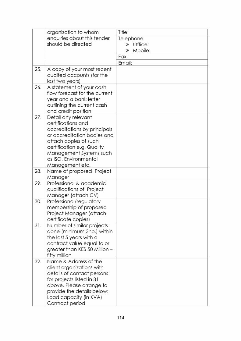
114
organization to whom
enquiries about this tender
should be directed
Title:
Telephone
Office:
Mobile:
Fax:
Email:
25. A copy of your most recent
audited accounts (for the
last two years)
26. A statement of your cash
flow forecast for the current
year and a bank letter
outlining the current cash
and credit position
27. Detail any relevant
certifications and
accreditations by principals
or accreditation bodies and
attach copies of such
certification e.g. Quality
Management Systems such
as ISO, Environmental
Management etc.
28. Name of proposed Project
Manager
29. Professional & academic
qualifications of Project
Manager (attach CV)
30. Professional/regulatory
membership of proposed
Project Manager (attach
certificate copies)
31. Number of similar projects
done (minimum 3no.) within
the last 5 years with a
contract value equal to or
greater than KES 50 Million –
fifty million
32. Name & Address of the
client organizations with
details of contact persons
for projects listed in 31
above. Please arrange to
provide the details below:
Load capacity (in KVA)
Contract period
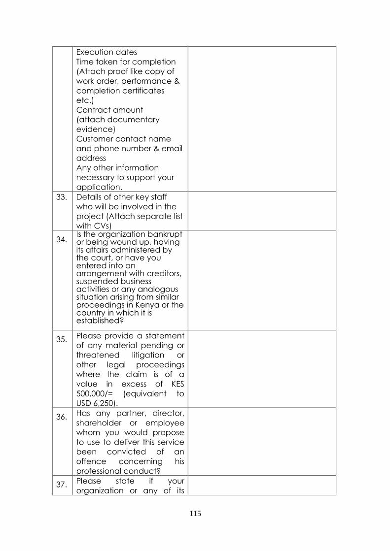
115
Execution dates
Time taken for completion
(Attach proof like copy of
work order, performance &
completion certificates
etc.)
Contract amount
(attach documentary
evidence)
Customer contact name
and phone number & email
address
Any other information
necessary to support your
application.
33. Details of other key staff
who will be involved in the
project (Attach separate list
with CVs)
34. Is the organization bankrupt or being wound up, having its affairs administered by the court, or have you entered into an arrangement with creditors, suspended business activities or any analogous situation arising from similar proceedings in Kenya or the country in which it is established?
35. Please provide a statement
of any material pending or
threatened litigation or
other legal proceedings
where the claim is of a
value in excess of KES
500,000/= (equivalent to
USD 6,250).
36. Has any partner, director,
shareholder or employee
whom you would propose
to use to deliver this service
been convicted of an
offence concerning his
professional conduct?
37. Please state if your
organization or any of its
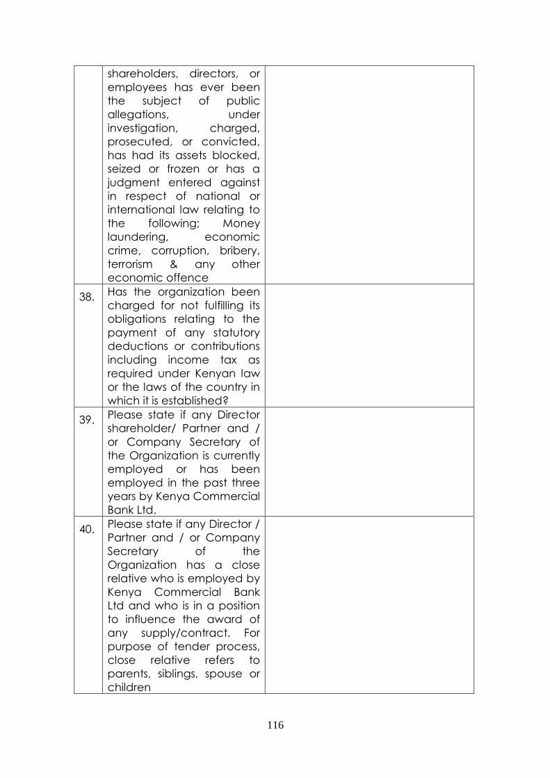
116
shareholders, directors, or
employees has ever been
the subject of public
allegations, under
investigation, charged,
prosecuted, or convicted,
has had its assets blocked,
seized or frozen or has a
judgment entered against
in respect of national or
international law relating to
the following; Money
laundering, economic
crime, corruption, bribery,
terrorism & any other
economic offence
38. Has the organization been
charged for not fulfilling its
obligations relating to the
payment of any statutory
deductions or contributions
including income tax as
required under Kenyan law
or the laws of the country in
which it is established?
39. Please state if any Director
shareholder/ Partner and /
or Company Secretary of
the Organization is currently
employed or has been
employed in the past three
years by Kenya Commercial
Bank Ltd.
40. Please state if any Director /
Partner and / or Company
Secretary of the
Organization has a close
relative who is employed by
Kenya Commercial Bank
Ltd and who is in a position
to influence the award of
any supply/contract. For
purpose of tender process,
close relative refers to
parents, siblings, spouse or
children

117
41. Please state if your
organization, any
predecessor to your
organization or any
member of your
organization is currently a
party to any litigation that is
in progress or has been
within the last three years
that is directly related to the
conduct of your business.
42. Please state if your
organization or any of its
shareholders, directors or
employees has ever offered
gifts or bribes to facilitate
award of business or to
facilitate payments or to
obtain business advantage.
43. Proposed contract period in
weeks for design, building,
shipping, delivery,
installation, testing and
commissioning (attach a
descriptive Gantt chart
copy).
Note: Please submit relevant photocopies of Registration/license/experience
/work order or other relevant document for above said declarations.

118
APPENDIX F – BILL OF QUANTITIES
PROPOSED POWER UPGRADE AT
KENCOM HOUSE
BILLS OF QUANTITIES FOR
ELECTRICAL INSTALLATION WORKS
BILL NO. 1
ITEM DESCRIPTION UNIT QTY RATE AMOUNT
A INCOMING POWER
SUPPLY AND GENERAL
ITEMS
A/1 Allow for incoming
electricity supply by KPLC
including metering
equipment (PROVISIONAL
SUM)
P.Sum 1 3,000,000.00 3,000,000.00
A/2 Supply, install and
connect complete 3
panel SF6 insulated,
indoor/outdoor non-
isolatable extensible
pattern, metal clad Ring
master switchboard
suitable for use on an
11Kv, 3 phase 3 wire,
50Hz, earthed neutral
system with an impulse
level of 95 Kv and fault
rating of 21KA for 3
seconds. The panel
being equipped with
2xHV cable boxes
suitable for accepting
cables from below and
comprising of the
following for the 2000kVA
transformer below under
item B/6 including all
fixing and connection of
all circuits from incoming
11kV power supply cable
by Kenya Power.
No. 1
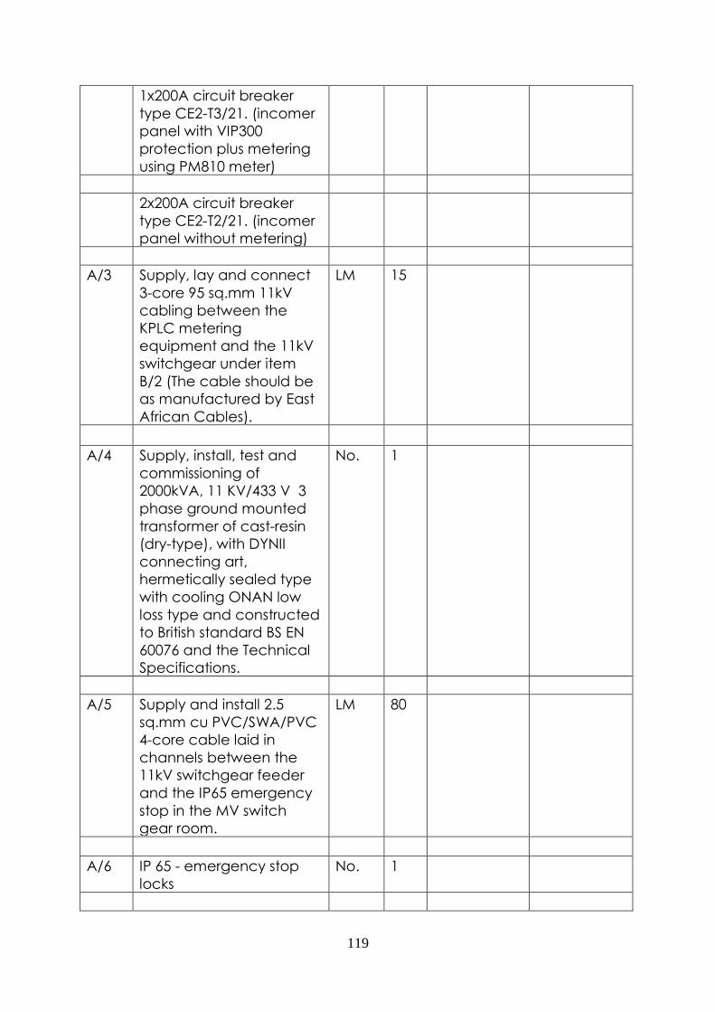
119
1x200A circuit breaker
type CE2-T3/21. (incomer
panel with VIP300
protection plus metering
using PM810 meter)
2x200A circuit breaker
type CE2-T2/21. (incomer
panel without metering)
A/3 Supply, lay and connect
3-core 95 sq.mm 11kV
cabling between the
KPLC metering
equipment and the 11kV
switchgear under item
B/2 (The cable should be
as manufactured by East
African Cables).
LM 15
A/4 Supply, install, test and
commissioning of
2000kVA, 11 KV/433 V 3
phase ground mounted
transformer of cast-resin
(dry-type), with DYNII
connecting art,
hermetically sealed type
with cooling ONAN low
loss type and constructed
to British standard BS EN
60076 and the Technical
Specifications.
No. 1
A/5 Supply and install 2.5
sq.mm cu PVC/SWA/PVC
4-core cable laid in
channels between the
11kV switchgear feeder
and the IP65 emergency
stop in the MV switch
gear room.
LM 80
A/6 IP 65 - emergency stop
locks
No. 1
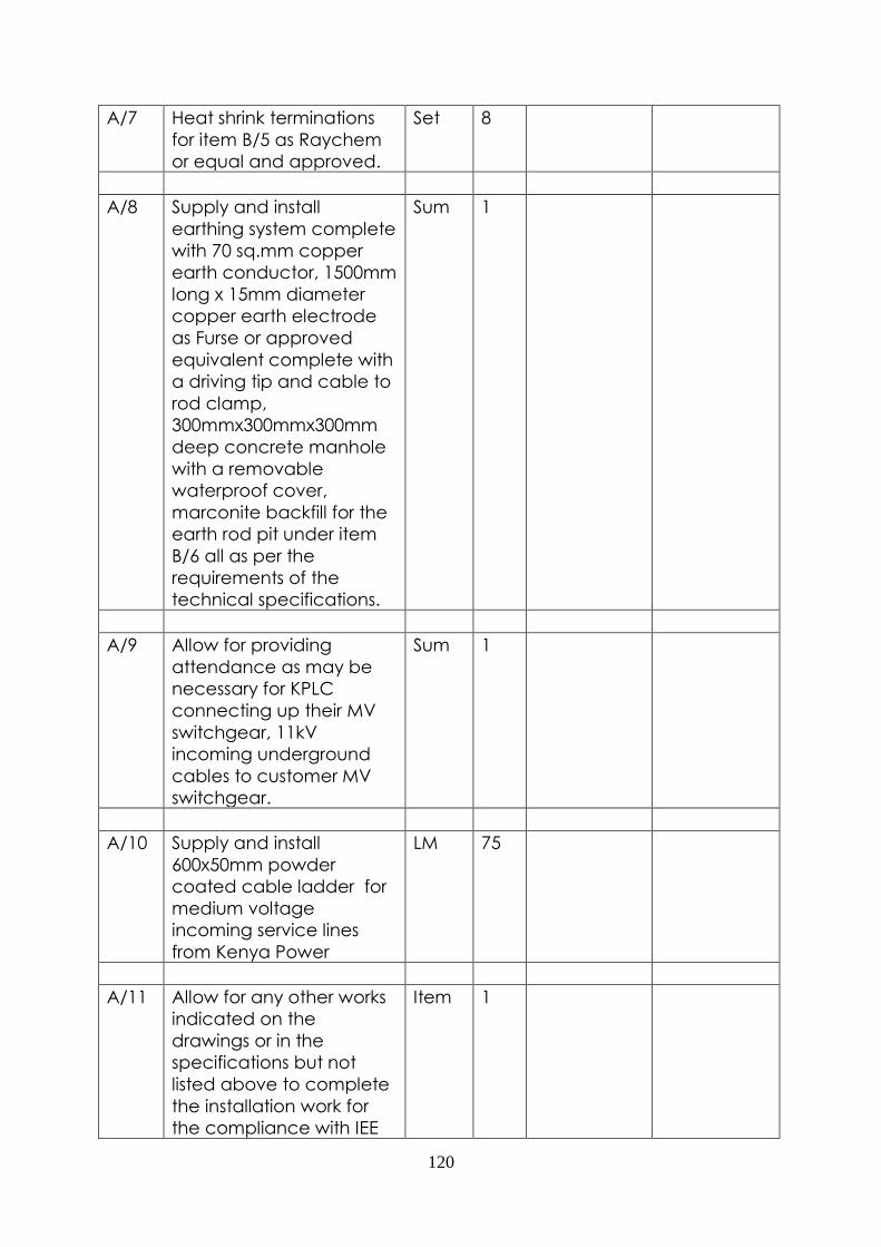
120
A/7 Heat shrink terminations
for item B/5 as Raychem
or equal and approved.
Set 8
A/8 Supply and install
earthing system complete
with 70 sq.mm copper
earth conductor, 1500mm
long x 15mm diameter
copper earth electrode
as Furse or approved
equivalent complete with
a driving tip and cable to
rod clamp,
300mmx300mmx300mm
deep concrete manhole
with a removable
waterproof cover,
marconite backfill for the
earth rod pit under item
B/6 all as per the
requirements of the
technical specifications.
Sum 1
A/9 Allow for providing
attendance as may be
necessary for KPLC
connecting up their MV
switchgear, 11kV
incoming underground
cables to customer MV
switchgear.
Sum 1
A/10 Supply and install
600x50mm powder
coated cable ladder for
medium voltage
incoming service lines
from Kenya Power
LM 75
A/11 Allow for any other works
indicated on the
drawings or in the
specifications but not
listed above to complete
the installation work for
the compliance with IEE
Item 1

121
Regulations and in
accordance with the
requirements of the
Kenya Power & Lighting
Company Ltd.
A/12 Allow for connection
units, bolts, nuts, cable
lugs, adaptable boxes,
supports, fixing, protective
painting, instructions of
owners, staff, samples
and tests, proposed
layout drawings and
record drawings.
Item 1
A/13 Allow for project site
administration works
which includes
preparation of program
of works, compliant to the
construction code,
construction safety code
and other necessary site
administration works.
Sum 1
A/14 Allow for necessary
submittals comprising
shop drawings,
illustrations, schedules,
product data, brochures,
samples and progress
photographs.
Sum 1
A/15 Allow for training of the
Client's maintenance
personnel in all aspects of
maintenance of the
entire electrical
installations (2 personnel
for 2 days)
Sum 1
A/16 Allow for supply of special
tools
Sum 1
A/17 Allow for supply of spare Sum 1

122
parts
A/18 Allow for factory
inspection of all
manufactured/fabricated
equipment prior to
delivery on site.
Sum 1
A/19 Allow for preparation of
operation and
maintenance manual
after complete
installation of the entire
electrical installations (3
sets)
Sum 1
A/20 Allow for the testing and
commissioning of the
incoming electricity
supply and low voltage
switchboard.
Sum 1
A/21 Allow for maintenance of
the 2000KVA transformer,
LV switchboard (old and
new) and the ring master
switchgear for a period of
3 years
Sum 1
A/22 Allow for assembly,
mechanical and
electrical operation of
11kV switchgear
Sum 1
A/23 Allow for Hot
commissioning once
mains supply is availed
Sum 1
A/24 Supply the following items
for fire fighting
(i) Fire ball code FES1 No. 20
(ii) 5kg fire extinguisher
Co2 code FEC005
No. 10
(iii) 9kg dry powder fire
extinguisher code FEDP09
No. 10
SUB-TOTAL CARRIED
FORWARD TO SUMMARY

123
PAGE
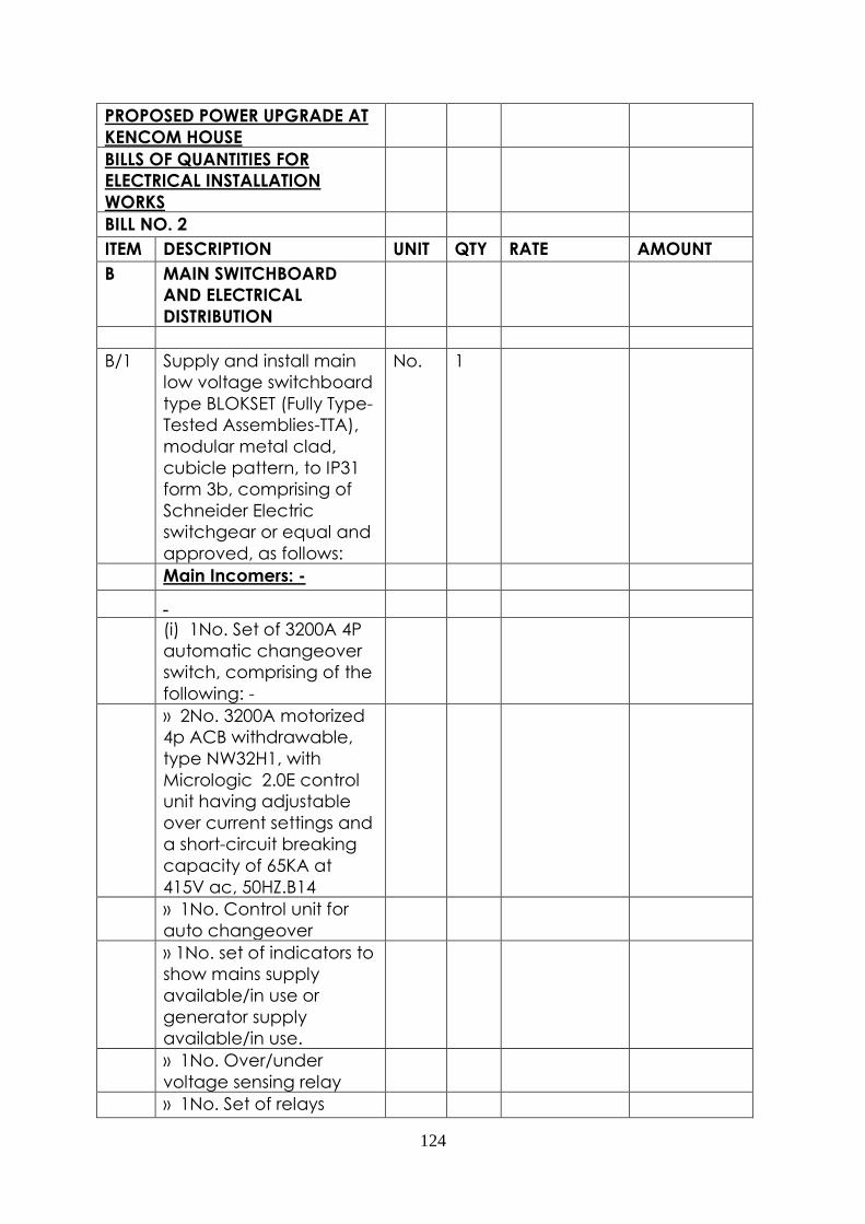
124
PROPOSED POWER UPGRADE AT
KENCOM HOUSE
BILLS OF QUANTITIES FOR
ELECTRICAL INSTALLATION
WORKS
BILL NO. 2
ITEM DESCRIPTION UNIT QTY RATE AMOUNT
B MAIN SWITCHBOARD
AND ELECTRICAL
DISTRIBUTION
B/1 Supply and install main
low voltage switchboard
type BLOKSET (Fully Type-
Tested Assemblies-TTA),
modular metal clad,
cubicle pattern, to IP31
form 3b, comprising of
Schneider Electric
switchgear or equal and
approved, as follows:
No. 1
Main Incomers: -
(i) 1No. Set of 3200A 4P
automatic changeover
switch, comprising of the
following: -
» 2No. 3200A motorized
4p ACB withdrawable,
type NW32H1, with
Micrologic 2.0E control
unit having adjustable
over current settings and
a short-circuit breaking
capacity of 65KA at
415V ac, 50HZ.B14
» 1No. Control unit for
auto changeover
» 1No. set of indicators to
show mains supply
available/in use or
generator supply
available/in use.
» 1No. Over/under
voltage sensing relay
» 1No. Set of relays

125
» 1No. Set of voltage free
normally closed/open
contacts for generator
start/stop signal.
(ii) 1No. Three-phase
surge arrestor type
DEHNventil DV TT 255
complete with
protection fuses.
(iii) 1No. Digital Energy
Multimeter type PM820
with RS485 modbus port
to monitor voltage,
current, KW, KWh, KVA,
frequency and power
factor, etc complete
with CTs and fuse
protection.
(iv) 3No. Phase presence
indicator lamps
Outgoers:-
(i) 1No. 2000A 3P ACB
withdrawable type (To
1000KVAR PFC Bank)
(ii) 1No 1600A 3P ACB
withdrawable type
(iii) 3No. 630A 3P MCCBs
(iv) 4No. 400A 3p
MCCBs
(v) 4No. 250A 3P MCCBs
B/2 Supply and install
earthing materials
comprising 1500mm
copper earth matts,
70mm sq. earth lead,
1800mm long x 15mm
diameter copper earth
electrode as furse or
approved equivalent
complete with a driving
tip and cable to rod
clamp,
500mmx500mmx500mm
deep concrete manhole
Sum 1

126
with a removable
waterproof cover,
marconite backfill for the
earth rod pit under item
B/7 all as per the
requirements of the
technical specifications.
B/3 Allow for labelling of the
LV switchboard under
Item C/1 above as per
the particular technical
specifications forming
part of tender
document.
Sum 1
B/4 Supply and install 1000
kVAr power factor
correction capacitor
bank type "BLOKSET"
(Fully Type-Tested
Assemblies-TTA),
modular, metal clad,
cubicle pattern, to IP20,
comprising of dry type
self-healing capacitors
type VARPLUS from
Schneider Electric,
complying with IEC 831
standards or equal and
approved:-
Sum 1
The PFC Bank will
comprise the following:-
(i) 19No. Varplus
Capacitor 50KVAR 415V,
50Hz, 3-phase
(ii) 2No. Varplus
Capacitor 25KVAR 415V,
50Hz, 3-phase
(iii) 21No. Special
contactors for capacitor
switching
(iv) 21No. Fuse bases
and fuses for each
capacitor protection
(v) 21No. Step indicator

127
lamps
(vi) 1No. Control circuit
protection fuse/fuse
holder
(vii) 1No. 12 step
automatic control
regulator for maintaining
power factor at the set
level and regulating the
switching of capacitor
steps
(viii) 3000/5A current
transformer (to be
mounted on the main
breaker)
B/5 Supply and connect 3-
core 95 sq.mm 11kV
cabling between the
2000kVA transformer and
the MV switchgear under
item B/2 (as
manufactured by East
African Cables).
LM 30
B/6 Supply and install 18x630
XLPE/PVC single core
cables from the 2000KVA
transformer to the new
main LV switchboard.
[The cables total run is
18x30m i.e. 510m]. (as
manufactured by East
African Cables)
LM 540
B/7 Supply and install 7x630
XLPE/PVC single core
cables from the 3200A
switchboard to the
existing LV switchboard
enclosed in channel and
cable ladders. [The
cables total run is 7x50m
i.e. 350m]. (as
manufactured by East
African Cables).
LM 350

128
B/8 Heat shrink terminations
for item C/6 as Raychem
or equal and approved.
Set 4
B/9 Supply and install brass
compression cable
glands complete with
shrouds and nuts for item
under C/5 above.
No. 36
B/10 Supply and install cable
lugs item under C/5
above.
No. 36
B/11 Allow for bonding of all
metal works, transformer,
MV switchgear, cable
ladder, cable trunking,
pipe work building steel
structure, cable trays
etc. as shown in the
main LV switchboard
schematic wiring on
drawing E001. The earth
bonding shall be carried
out using copper
conductor of 70 sq.mm
copper conductive
conductor. The
termination shall be
done through cable lugs
bolted firmly to each
end of the earth terminal
block and the
equipment/structure
bonded.
Sum 1
B/12 Supply, install and
connect (in the new
switchroom) free
standing changeover
bypass type block (Fully
Type-tested Assemblies -
TTA), modular, metal
clad, cubicle patern to
No. 1

129
IP31, form 1B comprising
of Merlin Gerin
Switchgear or equal and
approved as follows for
KCB Moi Avenue Branch.
630A Changeover
bypass
1No. 630A 4P
changeover bypass
comprising of
2No. 630A 4P Manual
changeover switches
B/13 Supply and install 4/c
185mmsq
cu/XLPE/SWA/PVC cable
from the new LV
switchboard to the Data
Centre sub board B and
remove the supply link
from the existing LV
switchboard to sub
board B. (as
manufactured by East
African Cables).
Lm 50
B/14 Supply and install 4/c
185mmsq
cu/XLPE/SWA/PVC cable
from the new LV
switchboard to the 630
bypass above and
connect as follows and
as manufactured by East
African Cables:
Lm 50
(i) Feeder 1: From sub
board B
(ii) Feeder 2: From the
new LV switchboard
The existing 4/c
120sqmm cable will
remain as the supply to
the branch.
B/15 Supply and install
300x50mm powder
LM 120

130
coated cable ladder for
low voltage incoming
service cables for the
client's utilities
B/16 Supply, lay and connect
new 8x630sqmm
XLPE/PVC single core
cables from the
2x500KVA standby
generators in the lower
basement to the new LV
switchboard. (The total
cable run is 8x50 = 400)
(as manufactured by
East African Cables).
LM 400
B/17 Allow for relocating the
existing cables from the
generator in the upper
basement to the new LV
switchboard
(4x630sqmm)
sum
B/18 Allow for transferring the
power cables (generator
in the upper basement)
from the existing LV
switchboard to the new
one.
sum 1
B/19 Supply, lay and connect
70sqmm XLPE/PVC single
core cable for
generators earthing (as
manufactured by East
African Cables).
Lm 90
B/20 Supply, lay and connect
300x50mm powder
coated cable ladder for
the maintained supply
cable
Lm 160
B/21 Allow for
decommissioning of the
No. 1

131
existing power factor
correction capacitor
bank from the existing LV
switchboard.
B/22 Allow for
decommissioning of the
existing automatic
changeover, system and
its cabling from the
existing LV switchboard
and the standby
generator.
Sum 1
B/23 Allow for testing and
commissioning the entire
electrical installations
under this section.
Sum 1
B/24 Supply and install 25mm
x 3mm horizontal
conductor copper tape
complete with saddles,
clamps and all other
necessary accessories
(Provisional Quantity) as
Furse or equal
equivalent.
LM 100
B/25 Supply and install lighting
points wired in 3x1.5
sq.mm PVC single core
cables running on a
150x50mm metal
trunking at high
level/surface galvanized
steel conduits without
switching accessories.
No. 17
B/26 Supply, install, connect,
testing and
commissioning the
following light fittings
complete with lamps as
follows:
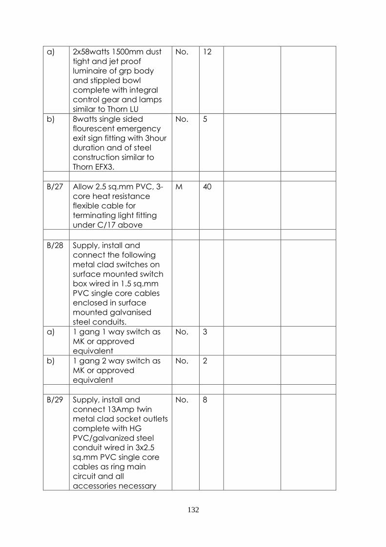
132
a) 2x58watts 1500mm dust
tight and jet proof
luminaire of grp body
and stippled bowl
complete with integral
control gear and lamps
similar to Thorn LU
No. 12
b) 8watts single sided
flourescent emergency
exit sign fitting with 3hour
duration and of steel
construction similar to
Thorn EFX3.
No. 5
B/27 Allow 2.5 sq.mm PVC, 3-
core heat resistance
flexible cable for
terminating light fitting
under C/17 above
M 40
B/28 Supply, install and
connect the following
metal clad switches on
surface mounted switch
box wired in 1.5 sq.mm
PVC single core cables
enclosed in surface
mounted galvanised
steel conduits.
a) 1 gang 1 way switch as
MK or approved
equivalent
No. 3
b) 1 gang 2 way switch as
MK or approved
equivalent
No. 2
B/29 Supply, install and
connect 13Amp twin
metal clad socket outlets
complete with HG
PVC/galvanized steel
conduit wired in 3x2.5
sq.mm PVC single core
cables as ring main
circuit and all
accessories necessary
No. 8

133
for recessed/surface
mounting.
B/30 Supply, install and
connect 15Amp twin
metal clad socket outlets
complete with HG
PVC/galvanized steel
conduit wired in 3x4.0
sq.mm PVC single core
cables as ring main
circuit and all
accessories necessary
for recessed/surface
mounting.
No. 2
B/31 Supply and install 10
sq.mm XLPE/SWA/PVC 4-
core cable from the LV
switchboard enclosed in
trench/cable tray to sub-
board TP in the power
room (as manufactured
by East African Cables).
LM 20
B/32 Supply and install 63
Amps, TP/N distribution
sub-board TP complete
with all MCCB's and PVC
blanking plate for the
spare ways as per the
drawings and any other
necessary accessories as
Merlin gerin or approved
equivalent.
No. 1
SUB-TOTAL CARRIED
FORWARD TO SUMMARY
PAGE

134
PROPOSED POWER UPGRADE AT
KENCOM HOUSE
BILLS OF QUANTITIES FOR
ELECTRICAL INSTALLATION
WORKS
BILL NO. 3
ITEM DESCRIPTION UNIT QTY RATE AMOUNT
C ELEMENT NO 1
DEMOLITIONS
The items of demolitions
and removal shall
include making good
disturbed areas to
match existing, keeping
on site all salvage
materials for client's use
and loading and carting
away debris unless
otherwise specified.
C/1 Allow a provisional sum
of fourty thousand
shillings for demolitions of
existing structures with a
plinth area of 10SQM
Item 1 40,000.00 40,000.00
C/2 Carefully demolish
200mm thick masonry
wall
Sum 106
C/3 Carefully remove
existing 2000x2000mm
high steel double door
No 1
C/4 Hack existing concrete
surface to allow for
placing of hardcore
(m/s)
Sum 67
ELEMENT NO. 2
SUBSTRUCTURE
CONCRETE
Vibrated reinforced
concrete class 25/20mm
(1:1:5:3) aggregate as
described in:
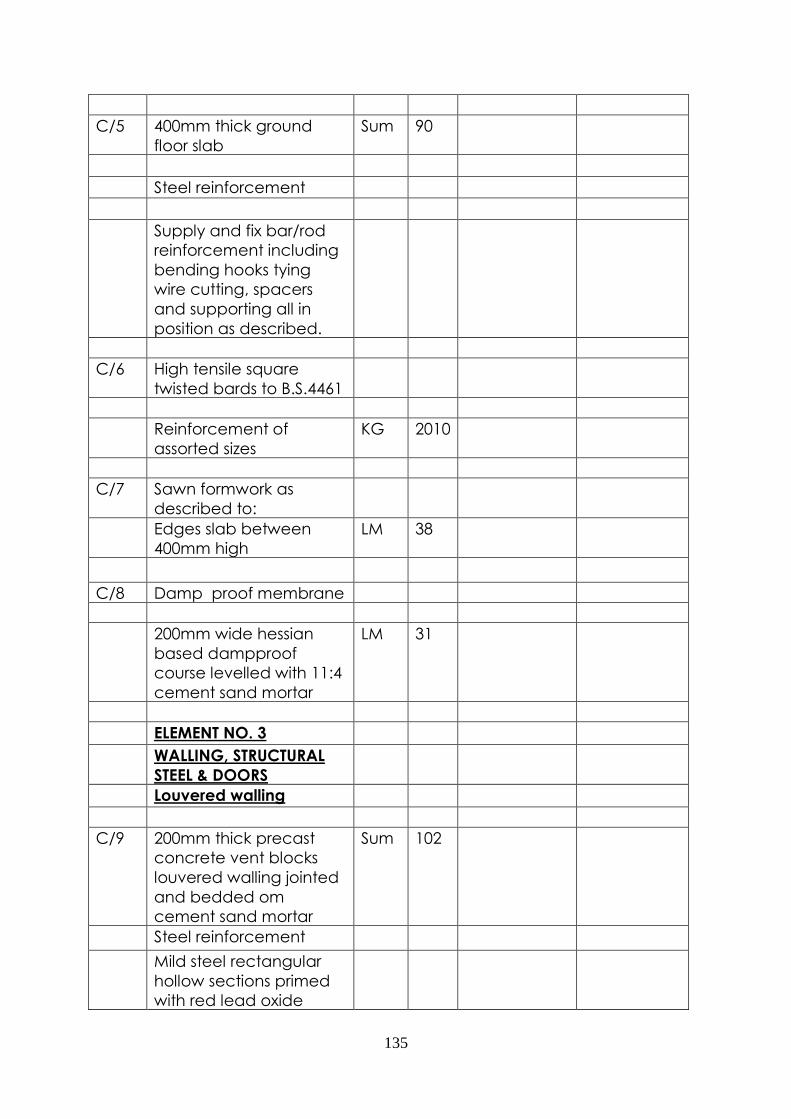
135
C/5 400mm thick ground
floor slab
Sum 90
Steel reinforcement
Supply and fix bar/rod
reinforcement including
bending hooks tying
wire cutting, spacers
and supporting all in
position as described.
C/6 High tensile square
twisted bards to B.S.4461
Reinforcement of
assorted sizes
KG 2010
C/7 Sawn formwork as
described to:
Edges slab between
400mm high
LM 38
C/8 Damp proof membrane
200mm wide hessian
based dampproof
course levelled with 11:4
cement sand mortar
LM 31
ELEMENT NO. 3
WALLING, STRUCTURAL
STEEL & DOORS
Louvered walling
C/9 200mm thick precast
concrete vent blocks
louvered walling jointed
and bedded om
cement sand mortar
Sum 102
Steel reinforcement
Mild steel rectangular
hollow sections primed
with red lead oxide

136
before fixing and fillet
welded together as
directed in:
C/10 50x50x4mm thick angle
line to hold RHS (m/s
LM 45
C/11 50x50x4mm thick RHS in
grating
LM 105
C/12 6mm thick mild steel
chequered plate
sum 80
Doors
Supply and fix the
following purpose made
doors
Steel metal door
C/13 Door size 2000x3000mm
high lourved steel metal
double door comprising
50x50x2mm thich SHS
framework; the door
infilled with 3mm thick
mild steel lourves,
complete with 3 pairs of
100mm heavy duty steel
butt hinges, 1No. Heavy
duty 20mm diameter all
drops, 2No. heavy duty
20mm diameter barrel
bolt.
No. 7
Painting
Prepare and apply one
undercoat and two
finishing coats of gloss oil
paint to:
C/14 General surfaces of
metal
sum 36
Sub-total carried forward
to Summary page

137
PROPOSED POWER UPGRADE AT
KENCOM HOUSE
BILLS OF QUANTITIES FOR
ELECTRICAL INSTALLATION
WORKS
BILL NO. 4
ITEM DESCRIPTION UNIT QTY RATE AMOUNT
D SUPPLY FAN 1
D/1 Adjustable Pitch
Aerofoil supply fan
capable of a volume
flow rate of 2m3/s
against a total pressure
drop of 200N/m2
Fan to be an aerofoil
extract fan complete
with supports, flexible
connections and anti-
vibration mountings.
Fan as "WOODS" Model
No. 71JM/20/4/6 with a
Pitch Angle of 8 deg.
Running at 1440 RPM, a
Power Supply of 1.4 kW
415V 50Hz and a total
weight of 198kg or
equal and approved.
Sum 1
Supply Fan 2
D/2 Adjustable Pitch
Aerofoil extract fan
capable of a volume
flow rate of 2m3/s
against a total pressure
drop of 150 N/m2
Fan to be an aerofoil
extract fan complete
with supports, flexible
connections and anti-
vibration mountings.
Fan as "WOODS" Model
No. 63JM/25/6/9 with a
No 1

138
Pitch Angle of 28 deg.
Running at 935 RPM, a
Power Supply of 1.55
kW 415V 50Hz and a
total weight of 85kg or
equal and approved.
Duct work
Galvanised mild steel
ductwork complete
with Bends, offsets,
hangers, supports,
sleeves, flanges, Access
doors, Test Holes,
stiffeners etc.
Supply Duct
D/3 800x650mm duct made
out of 0.8mm thick GMS
sheet
Lm 120
Exhaust Grille
D/4 700x700 large format
single deflection Heavy
duty aluminium exhaust
grille with individually
adjustable vanes at
38mm pitch, screw
fixed through nylon
bearings to prevent
vane vibration and
rattle. Waterloo Type
1K.
No. 2
Supply Grille
D/5 600x600 large format
single deflection Heavy
duty aluminium exhaust
grille with individually
adjustable vanes at
38mm pitch, screw
fixed through nylon
bearings to prevent
vane vibration and
rattle. Waterloo Type
No. 4

139
1K with opposing blade
dampers.
Dampers
D/5 800x650mm damper for
duct mounting with a
facility for adjustment
outside duct.
No. 2
Weather Grilles
D/6 Allow for a weather
grille approximately
1600x1800mm made
out of mild steel bars of
minimum 2mm
thickness.
No. 2
Internal Grilles
D/7 Allow for internal Air
Transfer grilles
approximately
700x700mm made out
of aluminium extrusion
with tubed cores and
mitred, welded frames.
The grille shall be as
"Waterloo Series NS"
No. 2
Supply Air Filter Box
D/8 Allow for a filter box
approximately
1400x1600x100mm thick
made out of 1.2mm
thick GMS sheets
complete with the
necessary filters and
filter brackets and
fixtures for 2m3/s air
flow.
No. 2

140
D/9 Allow for the removal of
existing steel grille to
allow for the installation
of the supply fan, filter
box and weather grille
and then the re-
installation of the same
steel grille and making
good by painting and
builders works.
No 2
Removal of the Existing
ductwork
D/10 Allow for the removal of
the existing or adapting
the existing ductwork
as necessary
Item 1
Electrical wiring
D/11 Allow for the electrical
wiring from the nearest
consumer untis to the
fans stated above
including the nessary
switching and safely
electrical appliance
Item 1
Testing and
Commissioning
D/12 Allow for setting to
work, testing and
commissioning of the
whole of the above
installations.
Item 1
Sub-total carried
forward to Summary
page
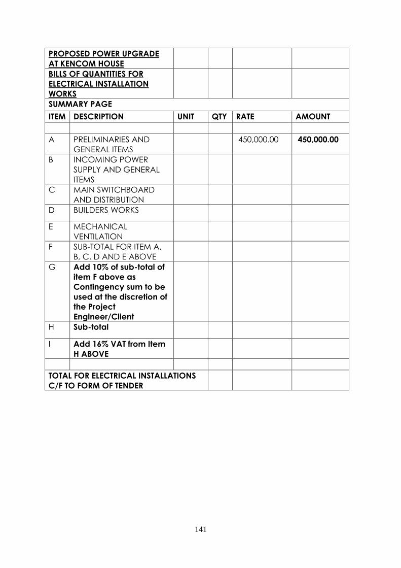
141
PROPOSED POWER UPGRADE
AT KENCOM HOUSE
BILLS OF QUANTITIES FOR
ELECTRICAL INSTALLATION
WORKS
SUMMARY PAGE
ITEM DESCRIPTION UNIT QTY RATE AMOUNT
A PRELIMINARIES AND
GENERAL ITEMS
450,000.00 450,000.00
B INCOMING POWER
SUPPLY AND GENERAL
ITEMS
C MAIN SWITCHBOARD
AND DISTRIBUTION
D BUILDERS WORKS
E MECHANICAL
VENTILATION
F SUB-TOTAL FOR ITEM A,
B, C, D AND E ABOVE
G Add 10% of sub-total of
item F above as
Contingency sum to be
used at the discretion of
the Project
Engineer/Client
H Sub-total
I Add 16% VAT from Item
H ABOVE
TOTAL FOR ELECTRICAL INSTALLATIONS
C/F TO FORM OF TENDER

142

143