temposonics - mts sensors · sensors provide best durability and accurate position measurement...
TRANSCRIPT

Temposonics®
Magnetostrictive Linear Position Sensors
EE AnalogData Sheet
– Pressure-resistant sensor rod– Compact sensor housing– High operating temperature
I 2 I
Temposonics® EE AnalogData Sheet
EE SENSOR
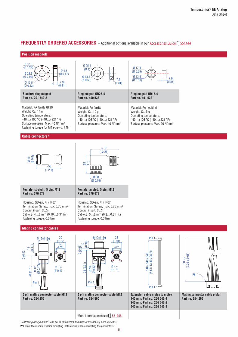
Robust, non-contact and wear free, the Temposonics® linear position sensors provide best durability and accurate position measurement solutions in harsh industrial environments. The position measurement accuracy is tightly controlled by the quality of the waveguide which is manufactured by MTS Sensors.
The Temposonics® E-Series EE position sensor is designed for the in-stallation into a hydraulic cylinder. Because of his compact design the EE sensor is the perfect solution for small cylinders with limited space for the integration in a measuring system. The increased operating temperature capability allows the sensor to be used in a wide range of industrial applications.
Fig. 2: Typical application: Wood working
MEASURING TECHNOLOGY
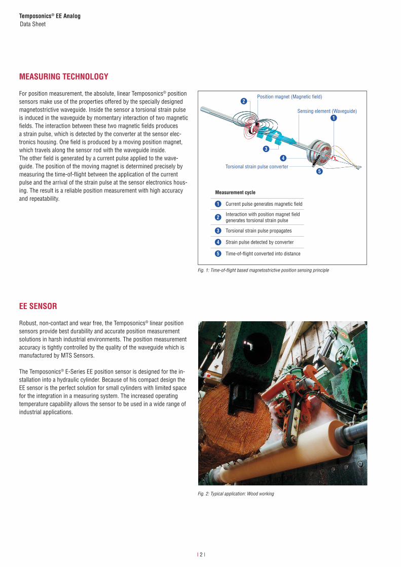
For position measurement, the absolute, linear Temposonics® position sensors make use of the properties offered by the specially designed magnetostrictive waveguide. Inside the sensor a torsional strain pulse is induced in the waveguide by momentary interaction of two magnetic fields. The interaction between these two magnetic fields produces a strain pulse, which is detected by the converter at the sensor elec-tronics housing. One field is produced by a moving position magnet, which travels along the sensor rod with the waveguide inside. The other field is generated by a current pulse applied to the wave-guide. The position of the moving magnet is determined precisely by measuring the time-of-flight between the application of the current pulse and the arrival of the strain pulse at the sensor electronics hous-ing. The result is a reliable position measurement with high accuracy and repeatability.
Fig. 1: Time-of-flight based magnetostrictive position sensing principle
4
5
3
1
Measurement cycle
1 Current pulse generates magnetic fi eld
2 Interaction with position magnet fi eld generates torsional strain pulse
3 Torsional strain pulse propagates
4 Strain pulse detected by converter
5 Time-of-fl ight converted into distance
Sensing element (Waveguide)
Position magnet (Magnetic fi eld)
Torsional strain pulse converter
2

I 3 I
Temposonics® EE Analog Data Sheet
TECHNICAL DATA
Output
Current 4…20 mA or 20…4 mA (minimum / maximum load: 0 / 500 Ω)
Measured value Position
Measurement parameters
Resolution Infinite
Cycle time < 3 ms
Linearity 1 < ±0.02 % F.S. (minimum ±60 µm)
Repeatability < ±0.002 % F.S. (minimum ±20 µm)
Operating conditions
Operating temperature −40…+85 °C (−40…+185 °F)
Humidity 90 % rel. humidity, no condensation
Ingress protection IP67 (with professional mounted housing and connectors), sensor with flat connector IP30
Shock test 100 g (single shock) / IEC standard 60068-2-27
Vibration test 15 g / 10…2000 Hz IEC standard 60068-2-6 (resonance frequencies excluded)
EMC test Electromagnetic emission according to EN 55011, cl. B:2009 + A1:2010 Electromagnetic immunity according to EN 61326-1:2006The sensor meets the requirements of the EC directives and is marked with .
Magnet movement velocity Any
Design/Material
Sensor electronics housing Stainless steel 1.4305 (AISI 303)
Sensor rod Stainless steel 1.4306 (AISI 304L)
Stroke length 50…2540 mm (2…100 in.)
Operating pressure Up to 350 bar (5076 psi)
Mechanical mounting
Mounting position Any
Mounting instruction Please consult the technical drawings and the operation manual(document number: 551415)
Electrical connection
Connection type 6 pin molex PicoBlade™ connector system
Operating voltage +24 VDC (−15 / +20 %)
Ripple ≤ 0.28 Vpp
Current consumption 50…140 mA
Dielectric strength 500 VDC (0 V ground to machine ground)
Polarity protection Up to −30 VDC
Overvoltage protection Up to 36 VDC
1/ With position magnet # 201 542-2

I 4 I
Temposonics® EE AnalogData Sheet
CONNECTOR WIRING
TECHNICAL DRAWING
5 pin connector M12 Function
1
2
3
4
5
Pin 1 +24 VDC (−15 / +20 %)
Pin 2 Output 1
Pin 3 DC Ground (0 V)
Pin 4 —
Pin 5 DC Ground
6 pin molex connector Molex Color Function
Pin 1
Pin 1 YE —
Pin 2 BL —
Pin 3 GY Output 1
Pin 4 WH DC Ground (0 V)
Pin 5 BK DC Ground
Pin 6 BN +24 VDC (−15 / +20 %)
With mating connector cable 254 256 and 254 560 With extension cable 254 642-x
Controlling design dimensions are in millimeters and measurements in ( ) are in inchesUnless otherwise stated, apply to the general tolerances according to DIN ISO 2768-m
6 pin molex connector Molex Color Function
Pin 1
Pin 1 YE —
Pin 2 — —
Pin 3 GY Output 1
Pin 4 WH DC Ground (0 V)
Pin 5 BK DC Ground
Pin 6 BN +24 VDC (−15 / +20 %)
With mating connector cable 254 266
Mag
net
6.25 (0.25)
8.5 (0.33)
Ø 48
f7(Ø
1.8
9 f7
)
Sensor electronics
housing24.6
(0.97 )
Null zone30
(1.18)
11.4
(0.4
5)
Ø 24
(Ø 0
.94)
Ø 10
± 0
.13
(Ø 0
.39
± 0.
01)
Stroke length50…2540(2…100)
Dead zone63.5(2.5)
110 / 310 / 610(4.33) / (12.20) / (24.02)
6 pin molex PicoBlade™ connector system molex grid = 1.25
2.5(0.10)
6.2(0.24)
16.1 (0.63)
2(0.08)
+0 -0.2
+0 -0.01
I 5 I
Temposonics® EE Analog Data Sheet
Position magnets
Ø 32.8(Ø 1.29)
Ø 23.8(Ø 0.94)
Ø 13.5(Ø 0.53)
Ø 4.3(Ø 0.17)
7.9(0.31)
Ø 25.4(Ø 1)
Ø 13.5(Ø 0.53) 7.9
(0.31)
Ø 13.5(Ø 0.53)
Ø 17.4(Ø 0.69)
7.9(0.31)
Standard ring magnetPart no. 201 542-2
Ring magnet OD25.4Part no. 400 533
Ring magnet OD17.4Part no. 401 032
Material: PA ferrite GF20Weight: Ca. 14 gOperating temperature: −40…+105 °C (−40…+221 °F)Surface pressure: Max. 40 N/mm2
Fastening torque for M4 screws: 1 Nm
Material: PA ferriteWeight: Ca. 10 gOperating temperature: −40…+105 °C (−40…+221 °F)Surface pressure: Max. 40 N/mm2
Material: PA neobindWeight: Ca. 5 gOperating temperature:−40…+105 °C (−40…+221 °F)Surface pressure: Max. 20 N/mm2
Cable connectors 2
~53(~ 2.1)
Ø 20
(Ø 0
.8)
38 (1.5
)
Ø 20(Ø 0.79)
~ 57(~2.25)
Female, straight, 5 pin, M12Part no. 370 677
Female, angled, 5 pin, M12Part no. 370 678
Housing: GD-Zn, Ni / IP67Termination: Screw; max. 0.75 mm²Contact insert: CuZnCable Ø: 4…8 mm (0.16…0.31 in.)Fastening torque: 0.6 Nm
Housing: GD-Zn, Ni / IP67Termination: Screw; max. 0.75 mm2
Contact insert: CuZnCable Ø: 5…8 mm (0.2…0.31 in.)Fastening torque: 0.6 Nm
Mating connector cables
12
(0.4
7)Ø
12(Ø
0.4
7)
44 (1
.73)
3 (0
.12)
Pin 1
M12×1−6g 20(0.79)
14(0.55)
Ø 3.4(Ø 0.13)
Pin 1
M12×1−6g
74 (2
.91)
24(0.94)
17(0.67)
Ø 4.4(Ø 1.73)Ø
16Ø
0.63
)
10(0
.39)
2 (0
.08)
Pin 1
Pin 1
140
/ 340
/ 64
0(5
.51/
13.
40 /
25.2
0)
60 ±
2(2
.36
± 0.
08)
Pin 1
5 pin mating connector cable M12Part no. 254 256
5 pin mating connector cable M12Part no. 254 560
Extension cable molex to molex140 mm: Part no. 254 642-1340 mm: Part no. 254 642-2640 mm: Part no. 254 642-3
Mating connector cable pigtailPart no. 254 266
More informationen see 551758
FREQUENTLY ORDERED ACCESSORIES – Additional options available in our Accessories Guide 551444
Controlling design dimensions are in millimeters and measurements in ( ) are in inches2/ Follow the manufacturer‘s mounting instructions when connecting the connectors

I 6 I
Temposonics® EE AnalogData Sheet
e Operating voltage
1 +24 VDC (−15 / +20 %)
b Design
S Pressure fit flange, 10 mm rod-Ø
1 2 3 4 5 6 7 8 9 10 11 12 13 14
a Sensor model
E E Rod
E E S 1
a b c d e f
f Output
A 0 1 4…20 mA
A 1 1 20…4 mA
15
ORDER CODE
c Stroke length
X X X X M 0050…2540 mm
X X X X U 002.0…100.0 in.
Stroke length Ordering steps
50… 500 mm 5 mm
500… 750 mm 10 mm
750…1000 mm 25 mm
1000…2540 mm 50 mm
Standard stroke length (mm)*
Stroke length Ordering steps
2… 20 in. 0.2 in.
20… 30 in. 0.5 in.
30… 40 in. 1.0 in.
40…100 in. 2.0 in.
Standard stroke length (in.)*
.
*/ Non standard stroke lengths are available; must be encoded in 5 mm / 0.1 in. increments
DELIVERY
Sensor, O-ring Accessories have to be ordered separately.
Operation manuals & software are available at: www.mtssensors.com
d Connection type
M 1 1 6 pin molex PicoBlade™ connector systemCable length 110 mm
M 3 1 6 pin molex PicoBlade™ connector systemCable length 310 mm
M 6 1 6 pin molex PicoBlade™ connector systemCable length 610 mm

UNITED STATESMTS Systems Corporation
Sensors Division
3001 Sheldon DriveCary, N.C. 27513Phone: +1 919 677-0100E-mail: [email protected]
GERMANYMTS Sensor Technologie
GmbH & Co. KG
Auf dem Schüffel 958513 LüdenscheidPhone: +49 2351 9587-0E-mail: [email protected]
ITALYBranch Office
Phone: +39 030 988 3819E-mail: [email protected]
FRANCEBranch Office
Phone: +33 1 58 4390-28E-mail: [email protected]
GREAT BRITAIN Branch Office
Phone: +44 79 44 15 03 00E-mail: [email protected]
CHINABranch Office
Phone: +86 21 6485 5800 E-mail: [email protected]
JAPANBranch Office
Phone: +81 42 707 7710E-mail: [email protected]
www.mtssensors.comMTS, Temposonics and Level Plus are registered trademarks of MTS Systems Corporation in the United States; MTS SENSORS and the MTS SENSORS logo are trademarks of MTS Systems Corporation within the United States. These trademarks may be protected in other countries. All other trademarks are the property of their respective owners. Copyright © 2018 MTS Systems Corporation. No license of any intellectual property rights is granted. MTS reserves the right to change the information within this document, change product designs, or withdraw products from availability for purchase without notice. Typographic and graphics errors or omissions are unintentional and subject to correction. Visit www.mtssensors.com for the latest product information.
Document Part Number: 551334 Revision D (EN) 03/2018
Reg.-No. 003095-QM08