template synthesis of iminodiacetic acid polysiloxane ...library.iugaza.edu.ps/thesis/111759.pdf ·...
TRANSCRIPT
The Islamic University – Gaza
Research and Graduate Affairs
Faculty of Science
Department of Chemistry
Template Synthesis of Iminodiacetic Acid Polysiloxane
Immobilized Ligand Systems and Their
Metal Uptake Capacity
المثبتة على أنظمة البولي حمض األسيتيكمينو ثنائي أالتحضير القالبي لمتصلة
الفلزات بعض أيونات على امتصاص سايلوكسان ودراسة قدرتها
Submitted by
Mohammad Khamees Selmi
Supervised by
Prof. Dr. Nizam M. El-Ashgar
Analytical Chemistry
Chemistry Department, Faculty of Science
The Islamic University of Gaza
A Thesis Submitted in Partial Fulfillment of Requirements for the Degree
of Master of Science in Chemistry
Chemistry Department
Gaza – Palestine
هـ 1434 – 2013م

II
III
DECLARATION
"I hereby declare that this manuscript is my own work and that, to
the best of my knowledge and belief, it contains no material
previously published, or written by another person, nor material
which to a substantial extent has been accepted for the award of
any other degree of the university or other institute, except
where due acknowledgment has been made in the text"
Signature: Moh. K. Selmi
Name: Mohammad Khamees Selmi
Date: September, 2013.
Copy Rights;
All Rights Reserved: No part of this work may be reproduced, translated or stored in
any kind of a retrieval system, without a prior permission of the author.
IV
ABSTRACT
Template Synthesis of Iminodiacetic Acid Polysiloxane
Immobilized Ligand System and Their
Metal Uptake Capacity
Two different routes for the synthesis of insoluble porous solid
functionalized ligand system bearing iminodiacetic acid chelating ligand of
the general formula P-(CH2)3N-(CH2COOH)2 (where P- represents [Si-O]n
polysiloxane network) were achieved by sol-gel template method in
presence of CTAB surfactant to formed porous materials. The first route
was achieved by the modification of 3-aminopropylpolysiloxane with
ethylchloroacetate, followed by hydrolysis with HCl to form the
polysiloxane iminodiacetic acid ligand system; P-(CH2)3N-(CH2COOH)2
(P-IDA-I). The second route was achieved by the reaction of
diethyliminodiacetate with 3-iodopropylpolysiloxane to form immobilized-
polysiloxane diethyliminodiacetate system. The diethyliminodiacetate
polysiloxane immobilized ligand system was then hydrolyzed by HCl to
form the iminodiacetic acid ligand system P-(CH2)3N-(CH2COOH)2
(P-IDA-II). Elemental analysis, 13
C NMR, XPS and FTIR results showed
that the surfactant have improved the silica network structure and increased
the metal uptake capacity of the ligand system. Thermogravimetric
analysis studies showed significant stability of the immobilized ligand
systems upon complexation with metal ions. The new functionalized ligand
systems exhibit high capacities for uptake of the metal ions
(Ni2+
, Cu2+
and Pb2+
).
Keywords: Metal Uptake, iminodiacetic Acid, diethyliminodiacetate,
surfacatants, immobilized-polysiloxane ligand systems.
V
ملخص
المثبتة على أنظمة البىلي سايلىكسان حمض األسيتيكمينى ثنائي أالتحضير القالبي لمتصلة
الفلزات بعض أيىنات على امتصاص ودراسة قذرتها
خ خحضش اماب خظت ثائ أسخاث -ح اسخخذا ساس خخف بطشمت اظ
األ واشوبت عى أظت ابى ساىوسا اظبت واسات راث اظغت
P-(CH2)3N-(CH2COOH)2 حث حث(P- شبىت ابى ساىوسا[Si-O]n) وره ف
أخ ححس اخشوب اشبى (Surfactant)راث افاعت اسطحت CTABوخىد ادة
ادة.
أىبشوب بى ساىوسا وره بخفاعها ع -3ح ححمك اساس األوي بخعذ خظت
إث وىسو أسخاث إلخاج ثائ إث أسخاث األ ث خبع ره اخح اائ دىعاث
ثىوس باسخخذا ح اهذسووىسه إلخاج اظغت احضت خظت احضشة وي اإل
P-(CH2)3N-(CH2COOH)2 , .(P-IDA-I)حائ ح أسخه األ راث اظغت:
ىدذ ابشوب بى -3أا اساس اثا فمذ ح ححممه بخفاع ثائ إث أسخاث األ ع
ساىوسا, إلحالي دىعت ثائ إث أسخاث األ زساث اىد و ث اخح اائ
ظت دىعاث اإلثىوس باسخخذا ح اهذسووىسه إلخاج اظغت احضت خ
, P-(CH2)3N-(CH2COOH)2 احضشة وي حائ ح أسخه األ راث اظغت:
.(P-IDA-II)
وأخهضة اخشخض Elemental Analysis) حب خالي خائح اخح اعظشي )
, وطاف اش اىوي اغاطس (FTIR)اطف واخ شج طاف األشعت ححج احشاء
(13
C NMR)طاف األشعت است افىحىاىخشوت , و(XPS) , بأ سشفاوخج ايCTAB لذ
ع عى ححس شبىت اسىا احات خظت ووزه صادة لذسة اخظت احضشة عى
(Thermogravimetric Analysis)اخظاص أىاث افضاث وا بج طشق اخح احشاسي
بأ يان دسخت ثباث حىظت خظت اشحبطت بظا ابى ساىوسا عذ االسحباط باىاث
افضاث اذسوست. إ اخظت ادذذة اشحبطت بظا ابى ساىوسا أظهشث لذسة عات
الخظاص اىاث فضاث اى و احاط واشطاص.

VI
DEDICATION
To my father and my mother who
taught me how to give
To my wife who supported me wholeheartedly
To my children
To my brothers and sister
To all my friends who spare no effort to help
To all of them I dedicate this work

VII
Acknowledgement
Praise be to Allah, the lord of the worlds and peace and blessings of
Allah be upon the noblest of the Prophets and Messengers, our Prophet
Mohammad.
This work has been carried out in the chemistry laboratories at the
Islamic university of Gaza, Palestine.
I wish to express my great thanks to Prof. Nizam M. El-Ashgar,
Professor of Analytical Chemistry and the former Dean of Faculty of
Science at the Islamic University of Gaza, the Supervisor of this work, for
his kind assistance, continuous and valuable advices.
I would like also to express my deepest gratitude and appreciation to
Prof. Issa M. El-Nahhal, Professor of Inorganic Chemistry at Al-Azhar
University of Gaza for supporting me during the experimental part
of my work.
I would like to thank Prof. Adel Awadalla, previous Head of the
Chemistry Department at the Islamic University of Gaza for great
assistance
and support.
I would like to express my deepest gratitude to Prof. Baker M.
Zabut, Professor of Biochemistry at the Islamic University of Gaza, he and
his coworkers that gave me a chance to study a master by inaugurate this
program in chemistry department.
I am also most grateful to all my professors in chemistry department
at the Islamic University of Gaza for the facilities they have
generously provided me.

VIII
I would like to thank all the technicians and staff of the chemistry
department in the Islamic university Gaza, especially Mr. Faraj Adwan
and Mr. Mohammed Matter for their help.
I would like also to express my thanks to all friends in the
master program for the great and lovely time that we spent together,
especially Mr. Mohammed Abu-Kmail for the nice spirit and stimulating
discussion all the time.
Finally, my thanks to everyone who helped me in my work,
that I may forgot him.
IX
TABLE OF CONTENTS
CHAPTER ONE
INTRODUCTION
Aim of this Research…………………………………………………………… 1
1.1 Definition of Heavy Metals …….....…………………….………..…………. 3
1.2 Extraction and Separation of Heavy Metals ………….…………..…………. 3
1.3 Criteria for Metal Ion Removal Method .……………….………..…………. 4
1.4 Types of Extraction Techniques. ………….….…..……..………..…………. 4
1.4.1 Solvent Extraction …………………………..………….……………….. 4
1.4.2 Polymer Filtration …………………..…..…………..………..…………. 5
1.4.3 Polymeric Ion Exchange Materials …………………..………..………... 5
1.5 Silica Based Solid Supports ……………………………..………..…………. 7
1.5.1 Silica Gel …………..………...……………...………………..…………. 7
1.5.2 Modification of Silica Gel ……………………………………………… 8
1.5.2.1 Physical Adsorption …………………………..…………………... 8
1.5.2.2 Chemical Immobilization …………...……………………..…..….. 8
1.5.3.3 Preparation of Chelating Sorbents Based on Silica Gel …………... 9
1.5.4.4 Preconcentration and Elution …………………...…………………. 9
1.6 Analytical Applications of Chelating Sorbents Based on Silica Gel ……….. 9
1.6.1 Polysiloxane Immobilized Ligand Systems …………..………..……….. 10
1.6.1.1 Definition of Polysiloxanes ………………………..……………. 10
1.6.1.2 Polysiloxanes Advantages …………...…………………………… 11
1.6.2 Preparation of Polysiloxane Immobilized Ligand System ….…………. 11
1.6.2.1 The Sol-Gel Process …………………………………..…………. 12
1.6.2.2 Steps of Sol–Gel Process ………………………………………… 12
X
1.6.2.2.1 Hydrolysis……………………………………………….. 12
1.6.2.2.2 Polycondensation………………………………………... 14
1.6.2.2.3 Gelation…………………………………………………. 16
1.6.2.2.4 Drying…………………………………………………… 16
1.6.2.2.5 Aging……………………………………………………. 16
1.7 Porous Materials……………………………………………………………... 17
1.8 Synthesis of Silica Networks Using Templates……………………………… 18
1.8.1 Template Definition……………………………………………………… 18
1.8.2 Surfactant-Templated Synthesis of Silica Networks…………………….. 18
1.8.2.1 Surfactants…………………………………………………………. 18
1.8.2.2 Types of Surfactants…………………...…………………………... 19
1.8.3 Synthesis Strategies of Mesoporous Materials………………...………… 19
1.8.4 Removal of Templates…………………………………………………… 20
1.8.5 Interactions Between Templates and Silica Precursors….………………. 21
1.8.6 Structures of Mesoporous Materials According to Surfactant Type…….. 22

XI
CHAPTER TWO
EXPERMINTAL PART
2.1 General Techniques …………………………………………..…..…………. 24
2.1.1 CP-MAS Solid State NMR Experiments ……………………....……..…. 24
2.1.2 X-ray Photoelectron Spectroscopy (XPS) ……………..……..…………. 24
2.1.3 Thermogravemetric Analysis …………….………..………………. 24
2.1.4 Elemental Analysis …………………………………......…….………… 25
2.1.5 Atomic Absorbtion Spectrophotometry ……………………..…..……... 25
2.1.6 Infrared Spectrophotometry …………………………..……..…….……. 25
2.1.7 pH Measurements ……………………………………..……..…………. 25
2.1.8 Shaking Techniques ……...………………………………..…..…..……. 25
2.2 Reagents and Materials ……………………………………….…..…………. 26
2.3 Metal Ions Solutions …………………………………..………….…………. 26
2.3.1 Standard Solutions ………………………..…………..….…..…………. 26
2.3.2 Stock Solutions ……………………………………..………..…………. 26
2.4 Buffer Solutions for pH Control……………..……………………………… 26
2.5 Preparations of Polysiloxane Iminodiacetic Acid Immobilized Ligand
System (P-IDA)……………… ………………………..……………………
27
2.5.1 Preparation of P-IDA-I from 3-Aminopropylpolysiloxane……………… 27
2.5.1.1 Preparation of 3-Aminopropylpolysiloxane Ligand System
(P-MA)…………………………………… ………………………
27
2.5.1.2 Preparation of polysiloxane Immobilized Diethyliminodiacetate
(P-DIDA-I)……………….. ……………..………………………..
27
2.5.1.3 Preparation of Polysiloxane Immobilized Iminodiacetic Acid
Ligand System (P-IDA-I)……………………………... ………….
28
XII
2.5.2 Preparation of P-IDA-II from 3-Iodopropylpolysiloxane………………. 28
2.5.2.1 Preparation of 3-Iodopropyltrimethoxysilane (L-I)……………….. 28
2.5.2.2 Preparation of Porous Polysiloxane 3-
Iodopropypolysiloxane Ligand System (P-
I)…….…..……………………………………
29
2.5.2.3 Preparation of Polysiloxane Immobilized Iminodiacetic Acid
Ligand System (P-IDA-II)….…………….……………………..
29
2.5.2.3.1 Preparation of Diethyliminodiacetate (DIDA)……………. 29
2.5.2.3.2 Immobilization Step………………………………………. 30
2.5.2.3.3 Hydrolysis Step………………………………………….. 30
2.6 Metal Uptake Experiments……………………...…………………………… 31
2.6.1 Effect of Shaking Time……………………..……………………………. 31
2.6.2 Effect of pH……………………………………………………………… 31
2.6.3 Effect of Shaking……………………………………...…………………. 32
2.6.4 Effect of Temperature …………….…………..…………….…………... 32

XIII
CHAPTER THREE
RESULTS AND DISCUSSTIONS
3.1 General Synthetic Methods of Polysiloxanes ……………..………………… 34
3.1.1 First Route: Preparation of P-IDA-I from 3-Aminopropylpolysiloxane. 35
3.1.1.1 Template Preparation of Porous Polysiloxane
3-Aminopropylpolysiloxane Ligand System (P-MA)…………..
35
3.1.1.2 Preparation of the P-DIDA-I and P-IDA-I Ligand Systems …... 36
3.1.2 Second Route: Preparation of P-IDA-II from 3-Iodopropylpolysiloxane. 37
3.1.2.1Template Preparation of Porous Polysiloxane
3- Iodopropypolysiloxane Ligand System (P-I) ………………...
37
3.1.2.2 Preparation of the P-DIDA-II and P-IDA-II Ligand Systems…… 38
3.2 FTIR Spectra ……………………………………………………..….………. 41
3.3 13C NMR Spectra ……………………………………………………………. 45
3.4 XPS Results ………………………………………………………...……... 46
3.5 Thermal Analysis………………………………………………… …………. 55
3.6 Metal Uptake Capacity ………………...……………………………………. 60
3.6.1 Effect of Surfactant Concentration……………………………………… 60
3.6.2 Effect of pH……………………………………………………………... 61
3.6.3 Effect of Temperature on Metal Uptake of P-IDA-I……………………. 62
3.6.4 Effect of Shaking………………………………………………………... 63
3.6.5 Comparison Between the Uptake of Different Metal Ions……………… 63
3.6.6 Effect of Shaking Time…………………………………………………. 64
Conclusion……………………………………………………………………….. 67
REFERENCES………………………………………………………………… 69

XIV
LIST OF SCHEMES
Scheme 1.1: Formation of polysilicic acid ……………………………………. 7
Scheme 1.2: Acid catalysis hydrolysis………………………..……………..…... 13
Scheme 1.3: Base catalysis hydrolysis………………………………..….……... 13
Scheme 1.4: Polycondensation of alkoxysilanes……………………..…………. 14
Scheme 1.5: Sol-Gel process…………………………………...…………...…... 15
Scheme 1.6: Aging process…………………………………...…………………. 16
Scheme 1.7: Cetyl Trimethyl Ammonium Bromide (CTAB)……………...…… 19
Scheme 3.1: Synthesis of polysiloxane mesoporous 3-aminopropypolysiloxane
ligand system (P-MA)……………………………………..……..
35
Scheme 3.2: Preparation of the P-DIDA-I and P-IDA-I ligand systems…….… 36
Scheme3.3:Template synthesis of polysiloxane mesoporous
3-iodopropypolysiloxane ligand system (P-I)…………………. …
37
Scheme 3.4: Preparation of the P-DIDA-II and P-IDA-II ligand systems…........ 38
XV
LIST OF FIGURES
Figure 1.1: Representative of the synthetic procedure of silica networks by
using surfactants as templates …………………………..………... 20
Figure 1.2: Interactions between inorganic species and different kinds of
surfactants in the formation of mesoporous materials…….……
22
Figure 3.1: FTIR spectra for (a) P-MA/CTAB, (b) P-MA, (c) P-DIDA-I and
(d) P-IDA-I, ligand systems (D-samples)...……….……..…..
42
Figure 3.2: FTIR spectra for (a) P-I/CTAB, (b) P-I, (c) P-DIDA-II and
(d) P-IDA-II, ligand systems (D-samples) ……..................…...
44
Figure 3.3: CP/MAS NMR 13
C spectra for (a) P-MA, (b) P-DIDA-I and
(c) P-IDA-I immobilized ligand systems of (D-samples)……….....
46
Figure 3.4: CP/MAS NMR 13
C spectra for the immobilized P-I/CTAB system
of (D-samples) ……………………………………..…………...
47
Figure 3.5: CP/MAS NMR 13
C spectra for the P-IDA-II system of (D-samples) 47
Figure 3.6: Survey regions of immobilized monoamine polysiloxane (a) (P-
MA/CTAB) in presence of CTAB and (b) after removal of CTAB.
48
Figure 3.7: Survey regions of (a) P-DIDA-I and (b) P-IDA-I…………….….. 49
Figure 3.8 (a): N1s regions from P-MA...………………………………………. 50
Figure 3.8 (b): N1s regions from P-IDA-I ……………………………………. 50
Figure 3.9: Survey regions of the (a) P-I/CTAB material and (b) P-I after
removal of CTAB ………..………………………....……...…...… 51
Figure 3.10:High resolution C1s regions from (a) P-I, (b) P-DIDA-II and
(c) P-IDA-II……………………………..……………………...… 52
Figure 3.11:High resolution N1s region for (a) P-I (b), P-DIDA-II and
(c) P-IDA-II……………….…………………………………...…. 53
Figure 3.12 (a): Thermograms of P-I prepared in absence of CTAB………..… 56
XVI
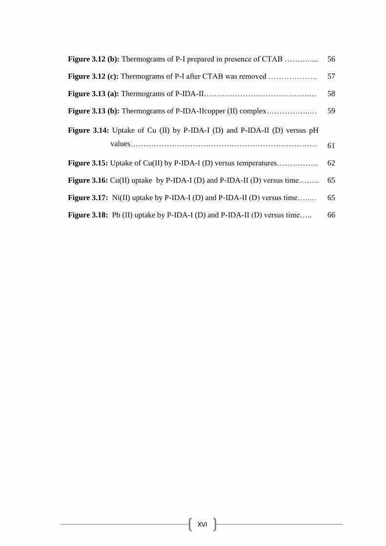
Figure 3.12 (b): Thermograms of P-I prepared in presence of CTAB …….….... 56
Figure 3.12 (c): Thermograms of P-I after CTAB was removed ………………. 57
Figure 3.13 (a): Thermograms of P-IDA-II………………….……………….… 58
Figure 3.13 (b): Thermograms of P-IDA-IIcopper (II) complex……………..… 59
Figure 3.14: Uptake of Cu (II) by P-IDA-I (D) and P-IDA-II (D) versus pH
values………………………………………………………………
61
Figure 3.15: Uptake of Cu(II) by P-IDA-I (D) versus temperatures……………. 62
Figure 3.16: Cu(II) uptake by P-IDA-I (D) and P-IDA-II (D) versus time…….. 65
Figure 3.17: Ni(II) uptake by P-IDA-I (D) and P-IDA-II (D) versus time…..… 65
Figure 3.18: Pb (II) uptake by P-IDA-I (D) and P-IDA-II (D) versus time….. 66
XVII
LIST OF TABLES
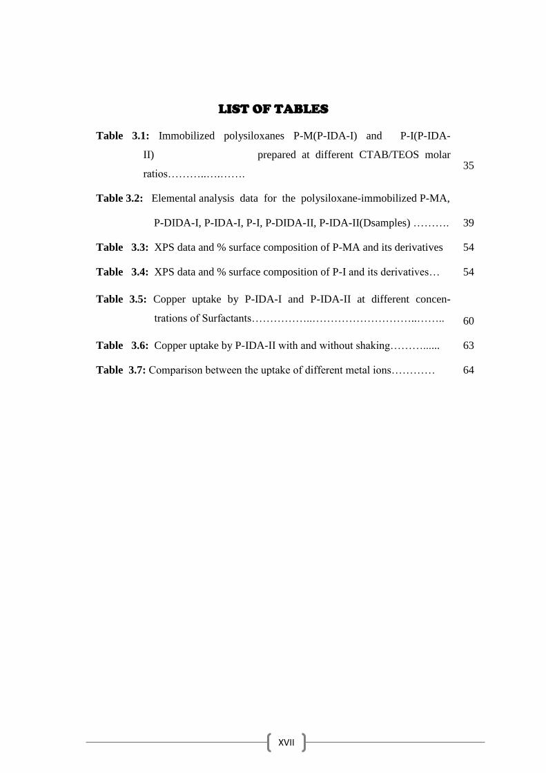
Table 3.1: Immobilized polysiloxanes P-M(P-IDA-I) and P-I(P-IDA-
II) prepared at different CTAB/TEOS molar
ratios………..….…….
35
Table 3.2: Elemental analysis data for the polysiloxane-immobilized P-MA,
P-DIDA-I, P-IDA-I, P-I, P-DIDA-II, P-IDA-II(Dsamples) ……….
39
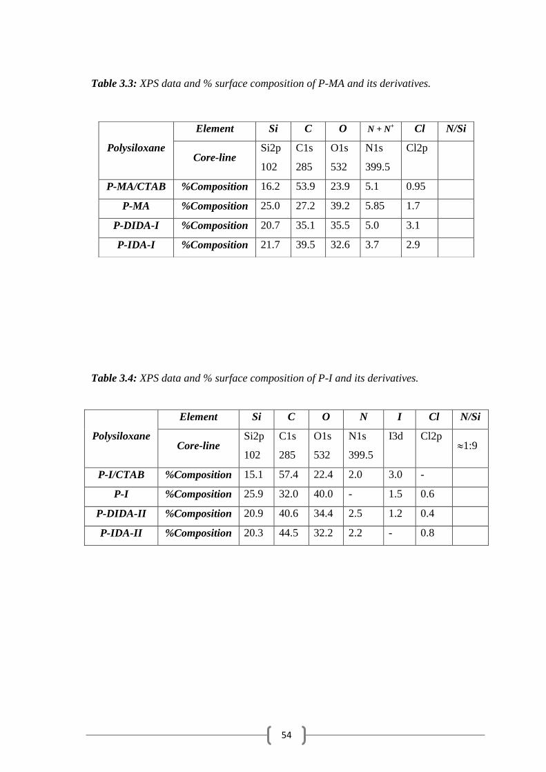
Table 3.3: XPS data and % surface composition of P-MA and its derivatives 54
Table 3.4: XPS data and % surface composition of P-I and its derivatives… 54
Table 3.5: Copper uptake by P-IDA-I and P-IDA-II at different concen-
trations of Surfactants……………..………………………..……..
60
Table 3.6: Copper uptake by P-IDA-II with and without shaking………...... 63
Table 3.7: Comparison between the uptake of different metal ions………… 64
XVIII
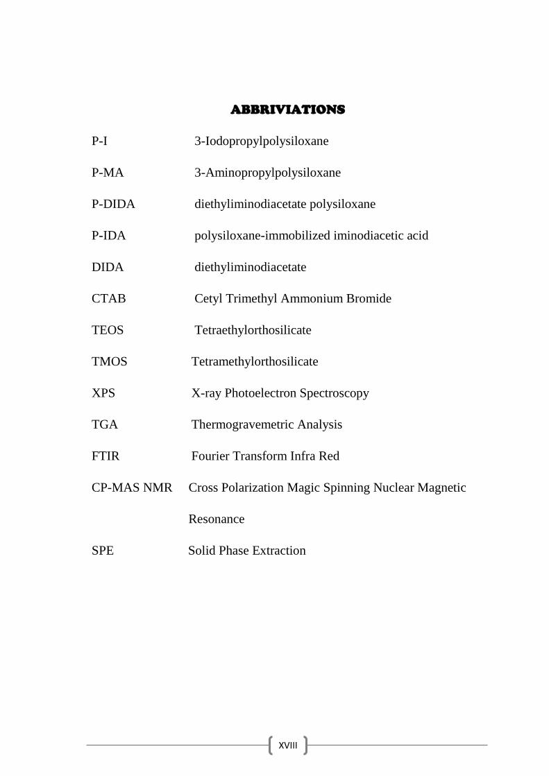
ABBRIVIATIONS
P-I 3-Iodopropylpolysiloxane
P-MA 3-Aminopropylpolysiloxane
P-DIDA diethyliminodiacetate polysiloxane
P-IDA polysiloxane-immobilized iminodiacetic acid
DIDA diethyliminodiacetate
CTAB Cetyl Trimethyl Ammonium Bromide
TEOS Tetraethylorthosilicate
TMOS Tetramethylorthosilicate
XPS X-ray Photoelectron Spectroscopy
TGA Thermogravemetric Analysis
FTIR Fourier Transform Infra Red
CP-MAS NMR Cross Polarization Magic Spinning Nuclear Magnetic
Resonance
SPE Solid Phase Extraction
1
Aim of this research
This work concerns with template synthesis of some of functionalized
chelating polysiloxane in presence of surfactants and to obtain porous
structure for the polymer which can be used for analytical applications such
as extraction, preconcentration and separation of some toxic heavy metals
from aqueous solutions.

2
CHAPTER ONE
INTRODUCTION

3
1.1. Definition of Heavy Metals.
Heavy metals can be defined as any metals or metalloids have density
more than 4 g/cm3, or 5 times or more greater than water [1,2], heavy
metals could enter the body system through food, air, water and bio-
accumulate over a period of time [1]. They are introduced and spread into
the environment through a number of industrial processes [3].
Some of heavy metals cause toxicity even if the concentrations are
very low and this is the main reason behind the price in the interest all over
the world [4], whereas others are biologically essential and become toxic at
relatively high concentrations, they combine with body's biomolecules, to
form stable biotoxic compounds, thus distortion their structures and
hindering them from the bioreactions of their functions [5].
Heavy metals combine with proteins and formed toxic complexes
and they can inactivate important enzyme systems [2].
1.2 Extraction and Separation of Heavy Metals.
Because of the toxicity of heavy metals there is an urgent need
for separation and preconcentration of the trace metals from different
media [6].
Direct determination using various instrumental methods is not
possible of trace metal ions present in various samples like natural and
waste water, biological and alloy samples, Because of matrix effects and
low concentration of metal ions in these samples, separation and
preconcentration of heavy metals can be occurred with various techniques
such as liquid–liquid extraction, precipitation technique, carbon adsorption,
distillation, evaporation, electrolytic concentration, capillary zone
electrophoresis, and use of chelating resins. However, the solid-phase
extraction of metal ions has gained rapid acceptance because of various
4
advantages, the extraction of metal ions using chelating resins is a very
important method since it does not involve the use of toxic chlorinated
organic solvents [7].
These techniques have been developed to remove the toxicity of
heavy metals because heavy metals are a non-degradable [3,8].
1.3 Criteria for Metal Ion Removal Methods [9].
1. A high metal ion sorption capacity.
2. Selective removal of one metal ion.
3. Operational across a range of pH values.
4. Reduction of metal ion concentrations to very low levels.
5. Mechanical and chemical integrity for an extended lifetime.
6. Economically available.
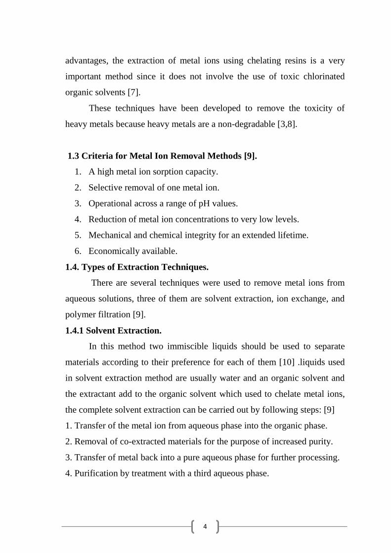
1.4. Types of Extraction Techniques.
There are several techniques were used to remove metal ions from
aqueous solutions, three of them are solvent extraction, ion exchange, and
polymer filtration [9].
1.4.1 Solvent Extraction.
In this method two immiscible liquids should be used to separate
materials according to their preference for each of them [10] .liquids used
in solvent extraction method are usually water and an organic solvent and
the extractant add to the organic solvent which used to chelate metal ions,
the complete solvent extraction can be carried out by following steps: [9]
1. Transfer of the metal ion from aqueous phase into the organic phase.
2. Removal of co-extracted materials for the purpose of increased purity.
3. Transfer of metal back into a pure aqueous phase for further processing.
4. Purification by treatment with a third aqueous phase.
5
1.4.2 Polymer Filtration.
It is an example of using water soluble chelating complexing agents
to selectively extract metal ions from aqueous solution [11]. For polymer
filtration, polymers are designed to form an ionic interaction or a
coordination complex with a target metal ion [12].
The polymer agent should be high molecular weight, chemical and
mechanical stability, low cost, low toxicity and reused. polyethyleneimine
is the most common one, it water soluble with a large degree of amine
groups which used as donor atoms in complex formation which provide a
greater degree of selectivity as a result of the specificity of complex
formation but it is toxic and cannot be used in water treatment applications,
some of acidic polymers include polyacrylic acid and polyvinyl sulfonic
acid are nontoxic and are relatively cheap. Unfortunately, they display low
selectivity for target metal ions relative to the polyamines [9].
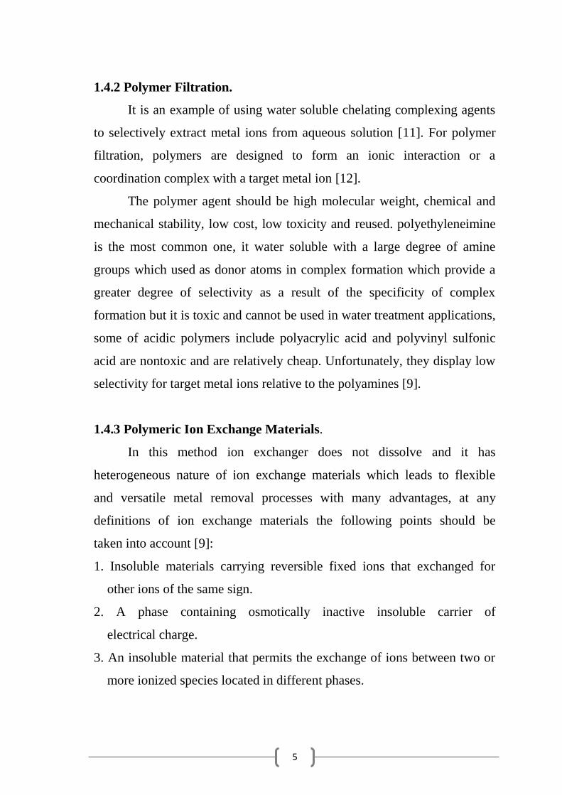
1.4.3 Polymeric Ion Exchange Materials.
In this method ion exchanger does not dissolve and it has
heterogeneous nature of ion exchange materials which leads to flexible
and versatile metal removal processes with many advantages, at any
definitions of ion exchange materials the following points should be
taken into account [9]:
1. Insoluble materials carrying reversible fixed ions that exchanged for
other ions of the same sign.
2. A phase containing osmotically inactive insoluble carrier of
electrical charge.
3. An insoluble material that permits the exchange of ions between two or
more ionized species located in different phases.

6
There are great similarities between Ion exchange and sorption. In
both a solid extracts a dissolved species. But the difference between them is
that Sorption removes species from solution without replacement the ions.
In contrast, ion exchange must satisfy balance of charge of the solution by
exchange ions with the solution, and the functional groups immobilized on
a solid support [13].
Chelating ion exchange materials is selective method. Therefore,
depending on the functional group it can have preference for one type of
metal ion over another, and it can be readily functionalized with a wide
range of ligands [14]. For an example, Amber lite IRC-748 resin has been
functionalized with an iminodiacetic acid chelating group; these groups
allow the resins to extract large amounts of metal ion at low pH [9].
The incorporation of chelating groups onto inorganic and
hybrid solid supports finding its way into an increasing
number of applications in areas such as extraction, recovery
and separation of metal ions from aqueous solutions which
prepared by the sol–gel method [15-23]. [15,16,17,18,19,20,21,22,23].
Chelating solid phases can be made by immobilizing appropriate
chelating agents on the support matrices for selective trace-metal analysis,
silica based chelating resins are most commonly used because
immobilization reactions on silica surface relatively simple and
reproducible, especially when compared to immobilization on organic
polymers, which involve complicated multi-step reactions [7].
To remove trace metals, solid-phase extraction (SPE) has become the
most commonly method often used, the basic principle of SPE is the
transfer of analytes from the aqueous phase to the active sites of the
adjacent solid phase, naphthalene, silica and silica gel, glass beads,
cellulose, polyurethane foam, molecular imprinted polymers and other
7
supports, are types of solid phase sorbent were developed to allow more
effective extractions [24].
1.5 Silica Based Solid Supports.
1.5.1 Silica Gel.
A lot of work has been done with organic ligand grafted onto silica
surface by chemical treatment. In this process organic ligand with metal
chelating ability is directly attached or can be easily loaded on silica gel to
produce the required immobilized ligand system [25].
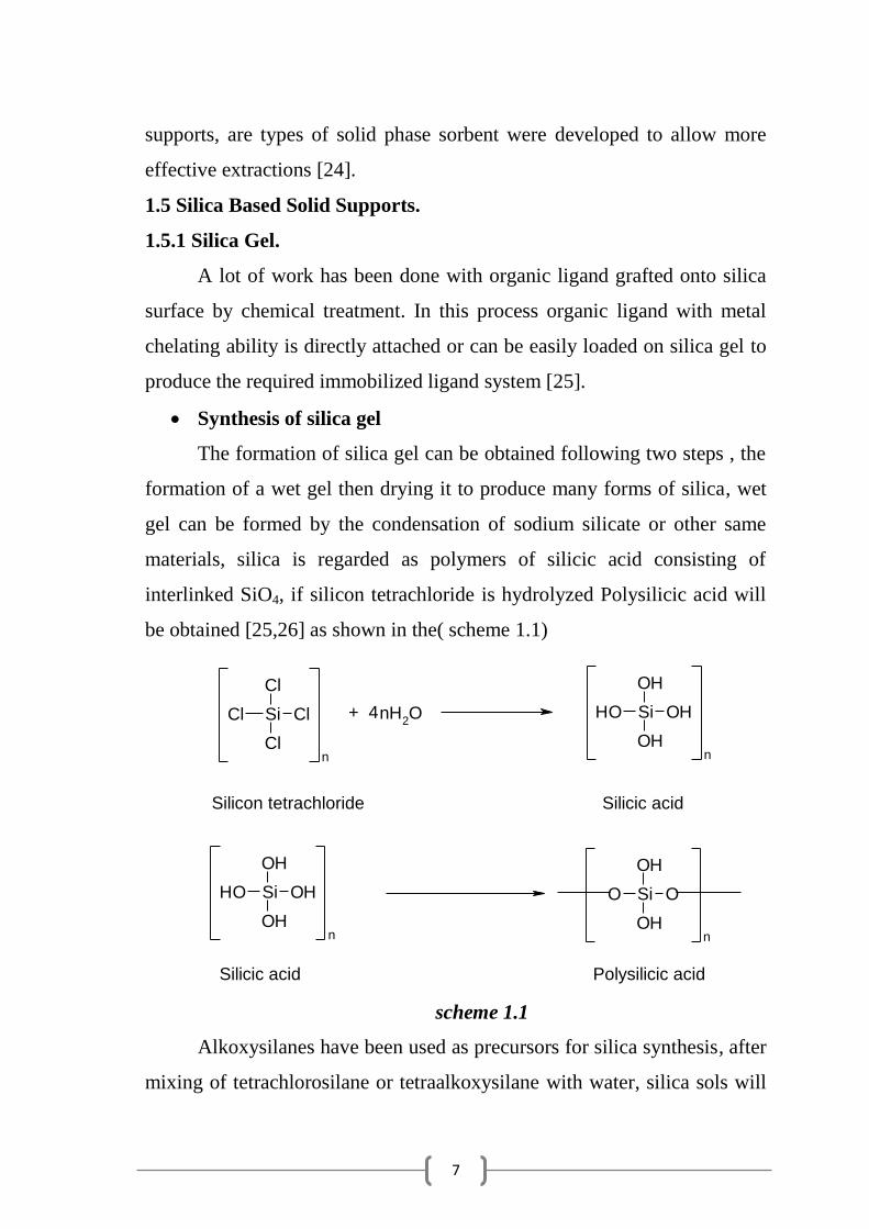
Synthesis of silica gel
The formation of silica gel can be obtained following two steps , the
formation of a wet gel then drying it to produce many forms of silica, wet
gel can be formed by the condensation of sodium silicate or other same
materials, silica is regarded as polymers of silicic acid consisting of
interlinked SiO4, if silicon tetrachloride is hydrolyzed Polysilicic acid will
be obtained [25,26] as shown in the( scheme 1.1)
Si Cl
Cl
Cl
Cl
n
nH2O Si OHOH
OH
OHn
Si OHOH
OH
OHn
Si OO
OH
OHn
+ 4
Silicon tetrachloride Silicic acid
Silicic acid Polysilicic acid
scheme 1.1
Alkoxysilanes have been used as precursors for silica synthesis, after
mixing of tetrachlorosilane or tetraalkoxysilane with water, silica sols will

8
be formed and by condensation small three dimensional siloxane network
are formed and the viscosity of the medium increased and at gel point the
gel will be formed [25]
advantages of silica gel
There are a lot of advantages in use of silica gel as an adsorbing
agent, it does not swell or strain, has good mechanical strength and thermal
stability, presence of silanol groups on the surface of silica gel cause low
interaction, binding and extraction of ionic species [27].
1.5.2 Modification of the silica gel
Two steps can be used to modified silica gel surface to obtain solid
sorbents with greater selectivity, physical adsorption and chemical
immobilization [28].
1.5.2.1 Physical Adsorption.
Here the organic compound will be adsorbed directly on the Si-OH
group either by passing the reagent solution through a column packed with
the adsorbent, nor by shaking the adsorbent in the reagent solution [28].
1.5.2.2 Chemical Immobilization.
In this way, a covalent bond is formed between the silica gel surface
groups and organic chelating ligand, thereby increasing the efficiency,
sensitivity and selectivity of the analytical applications than ion, simple
immobilization of the ligand on the silica surface by adsorption or
electrostatic interaction or hydrogen bond formation is the most convenient
ways to develop a silica surface [28].
9
1.5.2.3 Preparation of Chelating Sorbents Based on Silica Gel.
Two routs have been used to synthesis a lot of the polymeric
chelating sorbents:
1. The first one is the insertion of an appropriate functional group on the
surface of polymeric support and activated it.
2. The second is the immobilization of ligand with silica gel, and it is
widely used for preconcentration, separation and determination of trace
metal ions [24].
1.5.2.4 Preconcentration.
Chelating agents immobilized on silica gel support can form
complexes with metal ions only in certain pH ranges, so metal ions can
forms chelates with the chelating agent on the silica gel support and thus
are retained by the sorbent, but the impurities are not [24].
1.6 Analytical Applications of Chelating Sorbents Based on Silica Gel.
Extraction of metal ions using chelating sorbents has several
advantages over the conventional methods [24]:
1. Selective determination of metal ions by using a chelating sorbent.
2. There is no difficult phase separation, which is caused by the mutual
solubility between water and organic solvent layers.
3. It is an economical method since it uses only a small amount of ligand.
4. Trace metal ions at very low concentrations can be determined
5. Change in color intensity demonstrates the concentration of metal ions.
6. The technique is ecofriendly.
10
1.6.1 Polysiloxane Immobilized Ligand Systems.
1.6.1.1 Definition of Polysiloxanes.
Polysiloxane-immobilized ligand systems, functionalized poly-
siloxane sorbents, polyorganosiloxanes, or simply polysiloxanes are
intermediates polymers between the pure inorganic silica and organic
polymers such as polystyrene [25].
They are inorganic supports of silica based matrix bearing reactive
organic sites which have been the subject of considerable interest. These
types are known as functionalized polysiloxanes which have been prepared
either by the low temperature sol-gel process or by modification of pre-
prepared polysiloxane [29].
Flexibility of the siloxane backbone is the main reason of increasing
applications of polysiloxanes, this flexibility resulting from the degree
of Si–O–Si bond angle of 143° which is much more open than the usual
tetrahedral angle of 110°, and the Si–O bond is significantly longer than
the C–C bond [30].
Polysiloxane with chelating groups have a lot of important
applications, such as chromatography [31,32], extraction and uptake of
metal ions from aqueous solutions [33,34] and encapsulation of
organic compounds [35].
11
1.6.1.2 Polysiloxanes Advantages.
The advantages in used of polysiloxane-immobilized ligands are: [25].
1. Negligible swelling in different solutions.
2. Physical rigidity of their structures.
3. Nontoxic.
4. High biodegradation, photochemical and thermal stability.
5. High amount of functionalized groups.
6. Chemical inertness.
7. Uniform distributions of ligand sites within the polymer particles.
8. It can be modified easily by a variety of functional groups
9. High resistivity.
1.6.2 Preparation of Polysiloxane Immobilized Ligand System.
There are two common methods used to prepare these functionalize
ligand systems.
1. The first method is the sol-gel process which involves hydrolysis and
condensation of Si(OEt)4 with the appropriate silane coupling agent
(RO)3SiX where X represents an organofunctionalized ligand.
2. The second approach is the chemical modification of the pre-
prepared functionalized polysiloxane. The second method appears as
an interesting alternative mainly on account of substitution of
organofunctionalized groups when appropriate chelating silane
agents are difficult to prepare [36,37].
12
1.6.2.1 The Sol-Gel Process.
Sol gel method has attracted the attention of many researchers [38].
Sol-gel is a very flexible route for the synthesis of inorganic, organic
inorganic networks [39].
Sol-gel is a word consists of two syllables; the first is (sol) and its
mean the suspension of colloidal particles in solution, then when starting
sclerosis the gel will be formed [40] the sol-gel process can be obtained at
low temperature [39].
This process can be employed for the synthesis of functionalized
silica with controlled particle size and shape [41].
1.6.2.2 Steps of Sol–Gel Process.
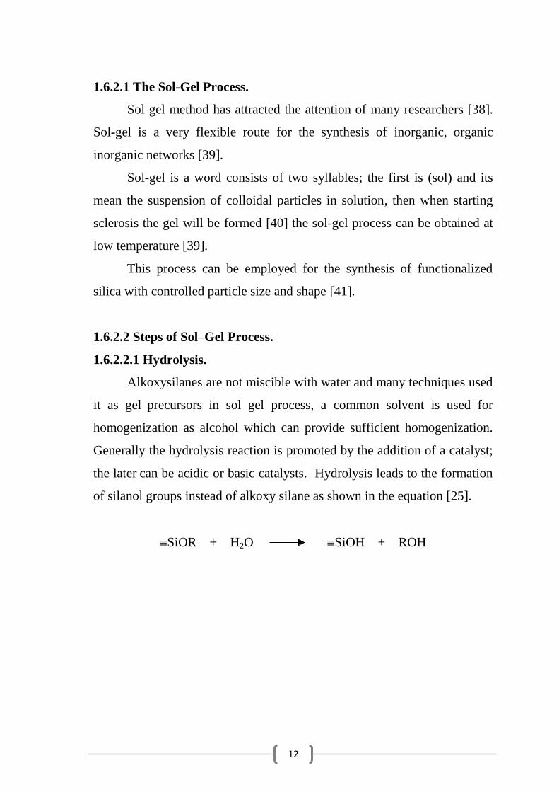
1.6.2.2.1 Hydrolysis.
Alkoxysilanes are not miscible with water and many techniques used
it as gel precursors in sol gel process, a common solvent is used for
homogenization as alcohol which can provide sufficient homogenization.
Generally the hydrolysis reaction is promoted by the addition of a catalyst;
the later can be acidic or basic catalysts. Hydrolysis leads to the formation
of silanol groups instead of alkoxy silane as shown in the equation [25].
SiOR + H2O SiOH + ROH
13
Si-OR Si-OR Si-OHH3O+ +
H
H2O
++ R-OH + H+
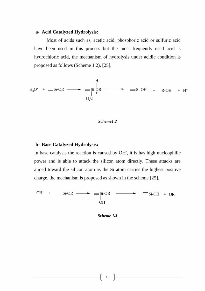
a- Acid Catalyzed Hydrolysis:
Most of acids such as, acetic acid, phosphoric acid or sulfuric acid
have been used in this process but the most frequently used acid is
hydrochloric acid, the mechanism of hydrolysis under acidic condition is
proposed as follows (Scheme 1.2). [25].
Scheme1.2
b- Base Catalyzed Hydrolysis:
In base catalysis the reaction is caused by OH-, it is has high nucleophilic
power and is able to attack the silicon atom directly. These attacks are
aimed toward the silicon atom as the Si atom carries the highest positive
charge, the mechanism is proposed as shown in the scheme [25].
Scheme 1.3
Si-OR Si-OR Si-OHOH +
OH
+ OR
14
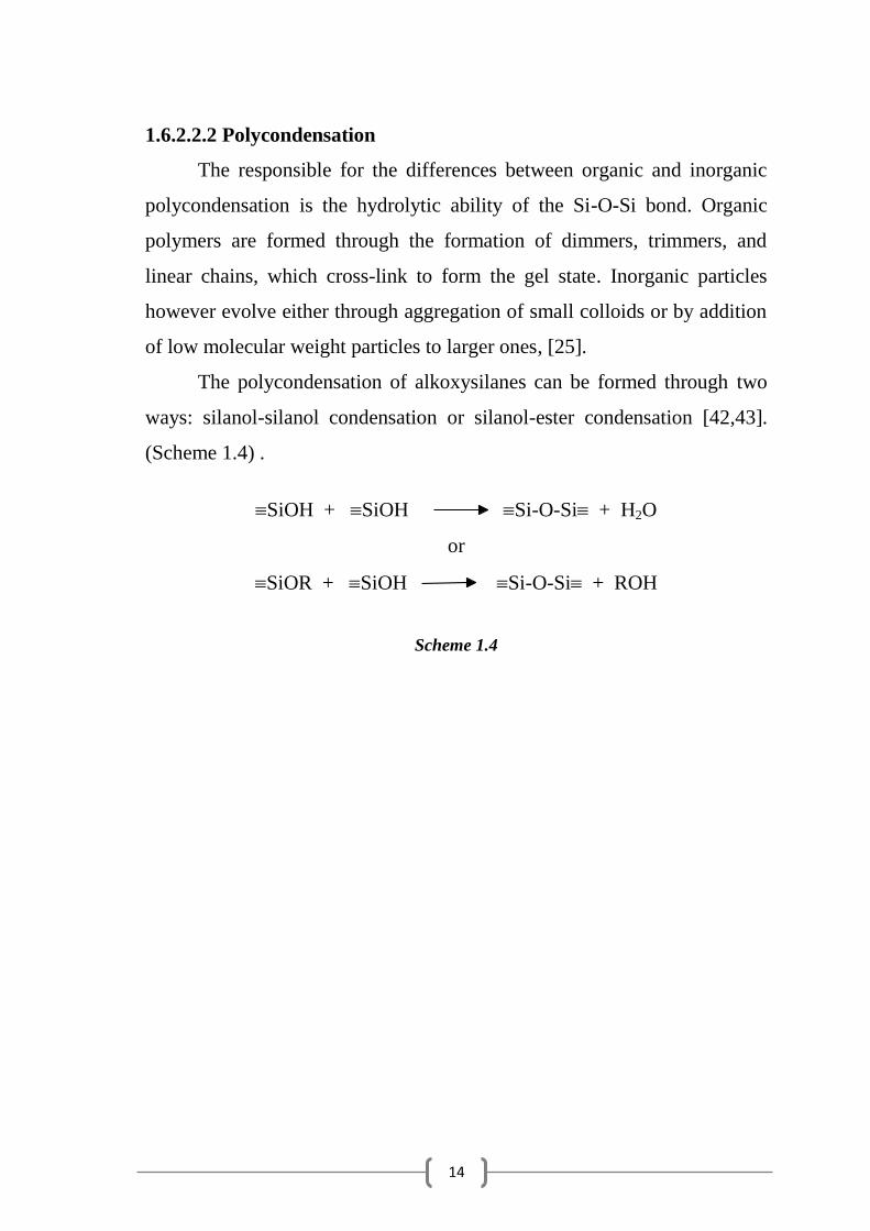
1.6.2.2.2 Polycondensation
The responsible for the differences between organic and inorganic
polycondensation is the hydrolytic ability of the Si-O-Si bond. Organic
polymers are formed through the formation of dimmers, trimmers, and
linear chains, which cross-link to form the gel state. Inorganic particles
however evolve either through aggregation of small colloids or by addition
of low molecular weight particles to larger ones, [25].
The polycondensation of alkoxysilanes can be formed through two
ways: silanol-silanol condensation or silanol-ester condensation [42,43].
(Scheme 1.4) .
SiOH + SiOH Si-O-Si + H2O
or
SiOR + SiOH Si-O-Si + ROH
Scheme 1.4
15
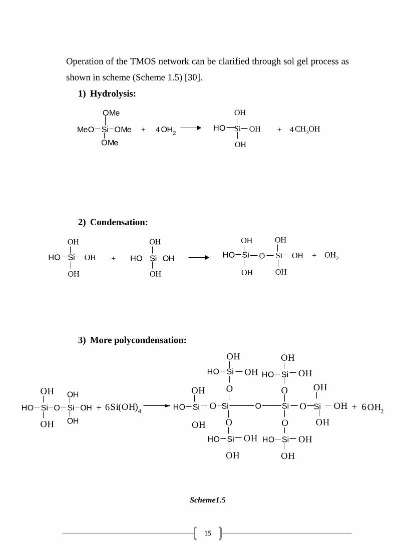
Operation of the TMOS network can be clarified through sol gel process as
shown in scheme (Scheme 1.5) [30].
1) Hydrolysis:
2) Condensation:
3) More polycondensation:
Scheme1.5
OH
OH
Si(OH)4
OH
OH
O OH
OH
OH
O
OH
O
OH
OH
O
OH
OH
O
OH
OH
O
OH
OH2SiOH O Si OH
OH
OH
SiOH SiOH
Si
SiOH
SiOSi
SiOH
SiOH+ 6 + 6
OH
OH
OH
CH3OHSi OMeMeO
OMe
OMe
OH2
OH+ 4 Si + 4
OH
OH
OH
OH
OH
OH
OH
OH
OH
OH
O OH2SiOH SiOHSi OHOH+ Si +
16
1.6.2.2.3 Gelation.
Increases interaction between particles increases viscous of the
solution and lose its fluidity and the gel is formed at gel point, when
polymerization is started, the Si-OH groups at the surface of the growing
particles are partly deprotonated and their negative charge provides a
repulsion barrier that stabilizes the sol. Latter, solvent evaporation and
water consumption by alkoxy silane hydrolysis concentrated the solution
and destabilize the suspension [30]
1.6.2.2.4 Drying.
In this stage water and other organic solvent evaporate from the
pores and the volume of the solid shrinks gradually and the final volume is
less than the initial, during this process, some of the larger pores are
emptied while smaller pores are still wet of the solvent, creating large
internal pressure gradients, this process causes cracking and fractures in
large monoliths, addition of surfactants or drying the wet gel under
monitored conditions prevents these fractures [42].
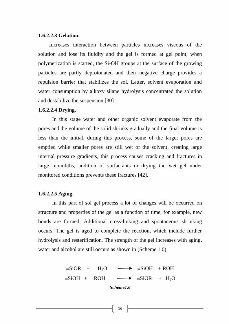
1.6.2.2.5 Aging.
In this part of sol gel process a lot of changes will be occurred on
structure and properties of the gel as a function of time, for example, new
bonds are formed, Additional cross-linking and spontaneous shrinking
occurs. The gel is aged to complete the reaction, which include further
hydrolysis and resterification. The strength of the gel increases with aging,
water and alcohol are still occurs as shown in (Scheme 1.6).
SiOR + H2O SiOH + ROH
SiOH + ROH SiOR + H2O
Scheme1.6

17
At ambient pressure and thermal evaporation xerogel is formed. But
aerogel can obtained under supercritical conditions [25].
There are several important factors controlling the structure and
properties of the sol-gel derived inorganic network such as pH,
temperature, time of reaction, reagent concentrations, catalyst constitution
and concentration, molar ratio of H2O/Si and aging temperature time [44].
1.7 Porous Materials.
Any materials containing pores called porous materials, and they
are classified to three types according to the size of the pores in
the target material, (microporous <2 nm, mesoporous 2-50 nm,
macroporous >50 nm ) [45].
M41S was the first mesoporous silica synthesized [46,47],
Preparation of porous materials taken special attention by researchers to be
used in many applications such as separation, catalysis, chemical sensing
and optical coating [48].
Mesoporos materials has possesses many characteristics such as,
highly ordered mesostructures, uniformly distributed pore size, large pore
volume and large surface area designable chemical composition and
functionalizable surface and controllable size and morphology [49].
18
1.8 Synthesis of Silica Networks Using Templates.
1.8.1 Template Definition.
Templating methods have opened the doors for researchers to design
and synthesis of ordered mesoporous materials [50], this methods described
as a central structure around which a network forms [51].
Removal of template (organic or inorganic) components can form
silica networks with porous internal environment with large specific
surface area aroused intense scientific interest for a variety of applications
including selective catalysis, drug delivery [52,53] and adsorption [54,55].
Many techniques have been used to achieve this target using natural
or synthetic inorganic or organic templates to form pores with controlled
structural features, zeolites, mesoporous molecular sieves, and silica gel are
inorganic compounds while surfactants, polymers, dendrimers, and other
colloidal particles are organic [40].
1.8.2 Surfactant-Templated Synthesis of Silica Networks.
1.8.2.1 Surfactants.
Surfactants are a shortened form of "surface-active agent" [56].
Surfactants contain both hydrophobic –tails– and hydrophilic –heads–
groups so they are amphiphilic compounds [57].
At higher concentration of surfactant more than the critical micelle
concentration (CMC) micelles can be obtained, continued increase in
concentration of surfactant in solution other forms can be found as
cylindrical micelles and then hexagonal arrays, cubic, and at very high
concentration lamellar phase can be obtained, but at very low concentration
Surfactants are present as free molecules [40].
All types of surfactants have been used as templates [58], these
template are used to form mesoporous materials [49]
19
1.8.2.2 Types of Surfactants.
There are three types of surfactants and they are classified according
to their charging properties [57].
Non-ionic surfactant (So): with neutral head groups, as ethyloxide or
propyloxide, alkyl polyesters, alkyl amines and others.
Anionic (S-) surfactant: with negatively charged head groups,
including alkyl carboxylate, phosphate, sulfate, sulphonate, etc.
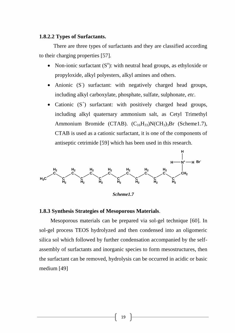
Cationic (S+) surfactant: with positively charged head groups,
including alkyl quaternary ammonium salt, as Cetyl Trimethyl
Ammonium Bromide (CTAB). (C16H33)N(CH3)3Br (Scheme1.7),
CTAB is used as a cationic surfactant, it is one of the components of
antiseptic cetrimide [59] which has been used in this research.
N+
H
HH
CH2
CH2
H2C
CH2
H2C
CH2
H2C
CH2
H2C
CH2
H2C
CH2
H2C
CH2
H2C
H3C
Br-
Scheme1.7
1.8.3 Synthesis Strategies of Mesoporous Materials.
Mesoporous materials can be prepared via sol-gel technique [60]. In
sol-gel process TEOS hydrolyzed and then condensed into an oligomeric
silica sol which followed by further condensation accompanied by the self-
assembly of surfactants and inorganic species to form mesostructures, then
the surfactant can be removed, hydrolysis can be occurred in acidic or basic
medium [49]
20
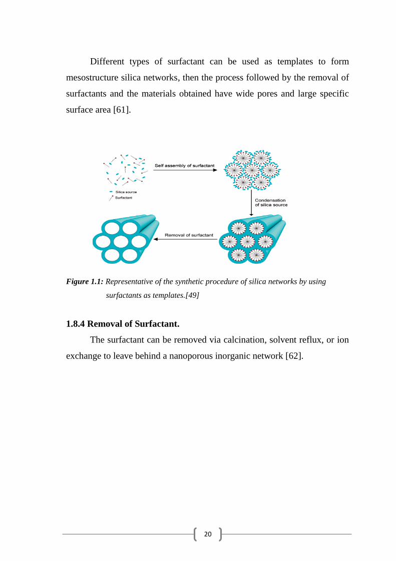
Different types of surfactant can be used as templates to form
mesostructure silica networks, then the process followed by the removal of
surfactants and the materials obtained have wide pores and large specific
surface area [61].
Figure 1.1: Representative of the synthetic procedure of silica networks by using
surfactants as templates.[49]
1.8.4 Removal of Surfactant.
The surfactant can be removed via calcination, solvent reflux, or ion
exchange to leave behind a nanoporous inorganic network [62].
21
1.8.5 Interactions between Templates and Silica Precursors.
There are different type of interactions between surfactant and
inorganic species in the synthesis of mesoporous materials [49],
First type explain the formation of ionic surfactant-templated
mesostructures in different pH values. [40]:
1. S+I
- : in the basic medium, silicate anions (I
-) combine with
cationic surfactant (S+).
2. S+X
-I
+: in acidic medium, protonated silicate (I
+) combines
with cationic surfactants (S+) after the addition of inorganic
ions X-, such as Cl
-, Br
-) .
3. S-I
+: in acidic medium, protonated silicate (I
+) combines with
anionic surfactants (S-).
4. S-M
+I
-: in basic medium, the addition of metal ions M
+, leads
to the combination of silicate anions (I-) with anionic
surfactants (S-).

22
The second type occurred by using nonionic surfactant:
1. SoI
o: or the ion pair.
2. SoIX
o: under acid conditions, inorganic ions X
- such as Cl
-
and Br- are needed), can be presented due to the formation of
hydrogen bonds or dipolar interaction between surfactant and
silica species (Fig. 1.2).
Figure 1.2: Interactions between inorganic species and different kinds of surfactants
in the formation of mesoporous materials [49].
1.8.6 Structures of Mesoporous Materials According to Surfactant
Type.
The structure of mesoporous materials is highly dependent on the
geometry of surfactant, including the size and charging of headgroups,
length and saturation of hydrophobic tail and its molecular shape,
cetyltrimethylammoniumbromide (CTAB) leads to formation of
2d-hexagonal (g = 1/2) structure easily [49].
Cationic surfactants were employed as templates to prepare
hexagonal [63] cubic [64] and lamellar mesoporous silica networks. [65].
23
CHAPTER TWO
EXPERIMENTAL PART
24
2.1 General Techniques.
2.1.1 CP-MAS Solid State NMR Experiments.
13C CP-MAS Solid State NMR experiments were carried out at room
temperature on Bruker MSL-400 MHz spectrometer at frequency of 100.6
MHz (13
C ) using a bruker CP/MAS probe. Proton decoupling was always
applied during acquisition. Solid samples were spun at 5 kHz using 7 mm
ZrO2 rotors filled in a glove-box under dried argon atmosphere.
2.1.2 X-ray Photoelectron Spectroscopy (XPS).
The X-ray photoelectric spectra (XPS) were recorded on an
ESCALAB 250, spectrometer equipped with a monochromatic AlK X-ray
source (hѵ = 1486.6 eV, 650 m spot size). An electron flood gun was used
to obtain a perfectly uniform static charge over the sample area analyzed.
The filament current was 3A and the emission current 0.2 mA. These
conditions yield negative but uniform static charge over the powder
surface. Binding energy positions were calibrated against the main
C-C/C-H C1s component set at 285 eV. The surface elemental composition
was determined by considering the peak areas and the corresponding
Scofield sensitivity factors corrected for the electron analyzer
transformation function.
2.1.3 Thermogravemetric Analysis.
Thermogravemetric analysis TGA was carried out using Mettler
Toledo SW 7.01 analyzer in the range of 25-600 oC under nitrogen.

25
2.1.4 Elemental Analysis.
Analysis for carbon, hydrogen, and nitrogen were carried out, using
an Elemental Analyzer EA 1110-CHNS CE Instrument.
2.1.5 Atomic Absorbtion Spectrophotometry.
The concentrations of metal ions in their aqueous solutions were
measured using a Perkin-Elmer AAnalyst-100, spectrometer.
2.1.6 Infrared Spectrophotometry.
The infrared spectra for the materials were recorded on a Perkin-
Elmer FTIR, spectrometer using KBr disk in the range 4000 to 400 cm1
.
2.1.7 pH Measurements.
All pH measurements were obtained using AD1020 pH Meter.
2.1.8 Shaking Techniques.
All ligand samples were shaken with aqueous metal ion solutions
using an ELEIA-Multi Shaker.

26
2.2 Reagents and Materials.
Tetraethylorthosilicate, 3-chloropropyltrimethoxysilane,
3aminopropy-trimethoxysilane, iminodiacetic acid and ethylchloroacetate
were purchased from (MERCK) and used as received. Acetone, diethyl
ether, tetrahydrofurane (THF) and ethanol (spectroscopic grade) were used
as received. Cetyltrimethylammoniumbromide (CTAB) surfactant was
purchased from MERCK and used as received. Surfactant solutions of
different concentrations were prepared in ethanol. Metal ions solutions
of the appropriate concentration were prepared by dissolving the
metal chloride or nitrate (analar grade) in distilled water. Different pH
values in the range (3.5 – 6) were controlled using acetic acid/sodium
acetate buffer solution.
2.3 Metal Ions Solutions.
2.3.1 Standard Solutions.
All standard solutions of metal ions were prepared from their chloride
or nitrate salts in analar grade by dissolving a known amount of the salt in
distilled water to the appropriate range of ion concentration (ppm).
2.3.2 Stock Solutions.
Metal ion solutions (Ni2+
, Cu2+
and Pb2+
) of appropriate concentrations,
were prepared by dissolving the metal chloride or nitrate in distilled water.
2.4 Buffer Solutions for pH Control.
Different pH values (3.5 – 6) were controlled using acetic acid / sodium
acetate buffer.

27
2.5 Preparations of Polysiloxane Iminodiacetic Acid Immobilized
Ligand System (P-IDA).
The target polymer was prepared by two routes as following.
2.5.1 Preparation of P-IDA-I from 3-Aminopropylpolysiloxane.
2.5.1.1 Preparation of 3-Aminopropylpolysiloxane Ligand System
(P-MA) [30].
Porous polysiloxane 3-aminopropylpolysiloxane ligand system (P-
MA) was prepared by adding 3-aminopropyltrimethoxysilane
(8.96 g, 0.05 mol) to a stirred solution of tetraethylorthosilicate
(20.83 g, 0.1 mol) in 15 cm3 ethanol in presence of CTAB. Different molar
ratios of CTAB/TEOS; 0:1(A), 1:32(B), 1:16(C) and 1:8(D) were used
(Table 1). 4.95 cm3 of 0.42 M HCl was added as a catalyst. The mixture
was stirred at room temperature and gelation occurred within few minutes.
The product was left to stand for 12 hours, and then dried in the oven at
90 oC. The solid material was crushed washed with water, ethanol and
diethyl ether and then dried at 100oC for six hours. CTAB was extracted
from the material using hot ethanol. The material was washed successively
with 50 cm3 portions of 0.025 M NaOH, water, ethanol and diethyl ether.
The product was then dried in oven at 100 oC for 12 hours.
2.5.1.2 Preparation of polysiloxane Immobilized Diethyliminodiace-
tate (P-DIDA-I) [30].
Diethyliminodiacetate polysiloxane was prepared by the reaction of
P-MA (5 g) with an excess of ethylchloroacetate (12.2 g, 0.1mol) in 50 cm3
of THF and 1.5 cm3 of triethyamine was added to react with the liberated
chloride. The mixture was stirred and refluxed at 95 oC for 48h. The
product was filtered off, washed with 0.025 M NaOH, water, ethanol and
diethyl ether, then dried at 100 oC for 12 hours.

28
2.5.1.3 Preparation of Polysiloxane Immobilized Iminodiacetic Acid
Ligand System (P-IDA-I) [30].
The immobilized diethyliminodiacetate polysiloxane, P-DIDA-I
(5.0 g) was hydrolyzed by refluxing the ligand system with 150 cm3 of 2.0
M HCl for 12 hours with stirring. The solid material was then filtered,
washed with 0.025 M NaOH aqueous solution, water, ethanol and diethyl
ether. The material was dried at 100 oC for 12 hours and polysiloxane
immobilized iminodiacetic acid ligand system (P-IDA-I) was obtained.
2.5.2 Preparation of P-IDA-II from 3-Iodopropylpolysiloxane.
2.5.2.1 Preparation of 3-Iodopropyltrimethoxysilane (L-I).
The 3-iodopropyltrimethoxysilane was prepared [42,66], by adding
3-chloropropyltrimethoxysilane (19.87 g, 0.10 mole) dropwise with stirring
to a solution of sodium iodide (15 g, 0.10 mole) in 100 cm3 of dry acetone,
at room temperature. The mixture was refluxed at 70 oC for 48 hours.
White solid of NaCl was filtered off and the solvent was removed under
reduced pressure (40 cm Hg), at 60 oC. The residue was extracted four
times using 100 cm3 of diethyl ether using a separatory funnel. The diethyl
ether was removed by distillation at 35 oC, producing a light
yellow oily product.
29
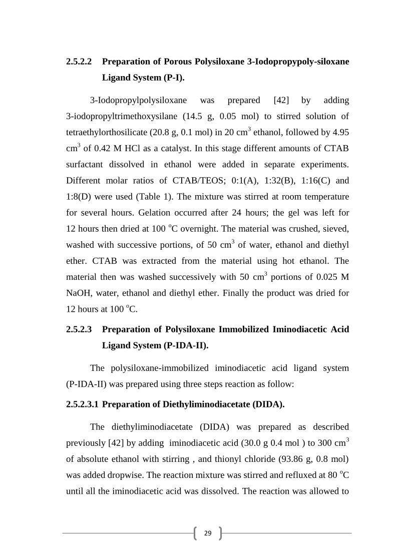
2.5.2.2 Preparation of Porous Polysiloxane 3-Iodopropypoly-siloxane
Ligand System (P-I).
3-Iodopropylpolysiloxane was prepared [42]
by adding
3-iodopropyltrimethoxysilane (14.5 g, 0.05 mol) to stirred solution of
tetraethylorthosilicate (20.8 g, 0.1 mol) in 20 cm3 ethanol, followed by 4.95
cm3 of 0.42 M HCl as a catalyst. In this stage different amounts of CTAB
surfactant dissolved in ethanol were added in separate experiments.
Different molar ratios of CTAB/TEOS; 0:1(A), 1:32(B), 1:16(C) and
1:8(D) were used (Table 1). The mixture was stirred at room temperature
for several hours. Gelation occurred after 24 hours; the gel was left for
12 hours then dried at 100 oC overnight. The material was crushed, sieved,
washed with successive portions, of 50 cm3 of water, ethanol and diethyl
ether. CTAB was extracted from the material using hot ethanol. The
material then was washed successively with 50 cm3 portions of 0.025 M
NaOH, water, ethanol and diethyl ether. Finally the product was dried for
12 hours at 100 oC.
2.5.2.3 Preparation of Polysiloxane Immobilized Iminodiacetic Acid
Ligand System (P-IDA-II).
The polysiloxane-immobilized iminodiacetic acid ligand system
(P-IDA-II) was prepared using three steps reaction as follow:
2.5.2.3.1 Preparation of Diethyliminodiacetate (DIDA).
The diethyliminodiacetate (DIDA) was prepared as described
previously [42] by adding iminodiacetic acid (30.0 g 0.4 mol ) to 300 cm3
of absolute ethanol with stirring , and thionyl chloride (93.86 g, 0.8 mol)
was added dropwise. The reaction mixture was stirred and refluxed at 80 oC
until all the iminodiacetic acid was dissolved. The reaction was allowed to
30
proceed under reflux for 5 hours, then cooled to room temperature and the
excess of ethanol and SO2 was removed by evaporation. The residue was
dissolved in 100 cm3 distilled water and 150 cm
3 of chloroform was added.
Then 33% of sodium hydroxide solution was added dropwise with shaking
after each addition, so that the diethyliminodiacetate passed into the
chloroform and pH of the solution was adjusted to around 7. The aqueous
layer was extracted repeatedly with chloroform (4 × 150 cm3). The layer of
chloroform was separated and then dried for 2 hours over anhydrous
MgSO4 the chloroform was removed by distillation
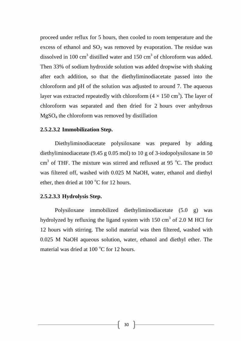
2.5.2.3.2 Immobilization Step.
Diethyliminodiacetate polysiloxane was prepared by adding
diethyliminodiacetate (9.45 g 0.05 mol) to 10 g of 3-iodopolysiloxane in 50
cm3 of THF. The mixture was stirred and refluxed at 95
oC. The product
was filtered off, washed with 0.025 M NaOH, water, ethanol and diethyl
ether, then dried at 100 oC for 12 hours.
2.5.2.3.3 Hydrolysis Step.
Polysiloxane immobilized diethyliminodiacetate (5.0 g) was
hydrolyzed by refluxing the ligand system with 150 cm3 of 2.0 M HCl for
12 hours with stirring. The solid material was then filtered, washed with
0.025 M NaOH aqueous solution, water, ethanol and diethyl ether. The
material was dried at 100 oC for 12 hours.
31
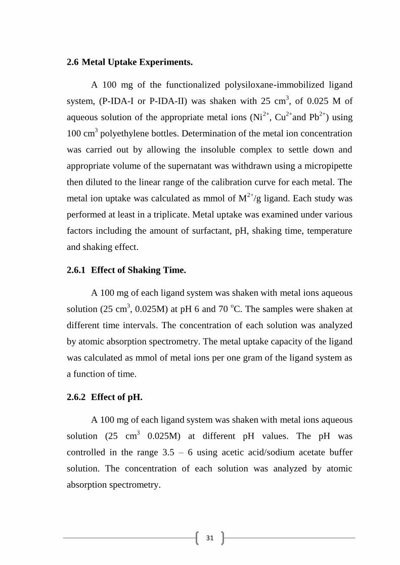
2.6 Metal Uptake Experiments.
A 100 mg of the functionalized polysiloxane-immobilized ligand
system, (P-IDA-I or P-IDA-II) was shaken with 25 cm3, of 0.025 M of
aqueous solution of the appropriate metal ions (Ni2+
, Cu2+
and Pb2+
) using
100 cm3 polyethylene bottles. Determination of the metal ion concentration
was carried out by allowing the insoluble complex to settle down and
appropriate volume of the supernatant was withdrawn using a micropipette
then diluted to the linear range of the calibration curve for each metal. The
metal ion uptake was calculated as mmol of M2+
/g ligand. Each study was
performed at least in a triplicate. Metal uptake was examined under various
factors including the amount of surfactant, pH, shaking time, temperature
and shaking effect.
2.6.1 Effect of Shaking Time.
A 100 mg of each ligand system was shaken with metal ions aqueous
solution (25 cm3, 0.025M) at pH 6 and 70
oC. The samples were shaken at
different time intervals. The concentration of each solution was analyzed
by atomic absorption spectrometry. The metal uptake capacity of the ligand
was calculated as mmol of metal ions per one gram of the ligand system as
a function of time.
2.6.2 Effect of pH.
A 100 mg of each ligand system was shaken with metal ions aqueous
solution (25 cm3 0.025M) at different pH values. The pH was
controlled in the range 3.5 – 6 using acetic acid/sodium acetate buffer
solution. The concentration of each solution was analyzed by atomic
absorption spectrometry.
32
2.6.3 Effect of Shaking.
Studying the effect of shaking on the capacity of metal uptake by the
functionalized polysiloxane system was carried out by mixing 100 mg of
ligand system with M2+
aqueous solution (25 cm3 0.025M ) at pH 6, 70
oC
for 72 hours using acetate buffer. The metal uptake was measured with
shaking and without shaking in separate experiments.
2.6.4 Effect of Temperature.
A 100 mg of each ligand system was shaken with metal ions aqueous
solution (25 cm3 0.025M) at pH 6 for 72 hours in different temperature
(25-70) o
C using acetic acid/sodium acetate buffer solution. The
concentration of each solution was analyzed by atomic
absorption spectrometry.

33
CHAPTER THREE
RESULTS AND
DISCUSSION
34
3.1 General Synthetic Methods of Polysiloxanes.
The porous functionalized polysiloxane immobilized iminodiaacetic
acid ligand systems, P-IDA, was prepared in two different routes based on
sol-gel process.
The first route was achieved by the following steps [36]:
i. Preparation of porous 3-aminopropylpolysiloxane functionalized
system (P-MA) in presence of CTAB surfactant by the sol-gel
process.
ii. Preparation of polysiloxane-immobilized diethyliminodiacetate
(P-DIDA) by the reaction of ethylcholoroacetate with
3-aminoropylpolysiloxane P-MA in presence of THF.
iii. Hydrolysis of P-DIDA by HCl to form polysiloxane-immobilized
iminodiacetic acid (P-IDA-I).
The second route was achieved by the following steps [48]:
i. Preparation of porous 3-iododopropylpolysiloxane functionalized
system (P-I) in presence of CTAB surfactant by the sol-gel process.
ii. Preparation of polysiloxane-immobilized diethyliminodiacetate
(P-DIDA) by the reaction of diethyliminodiacetate with
3-iodopropylpolysiloxane in THF.
iii. Hydrolysis of P-DIDA by HCl to form polysiloxane-immobilized
iminodiacetic acid (P-IDA-II).
35
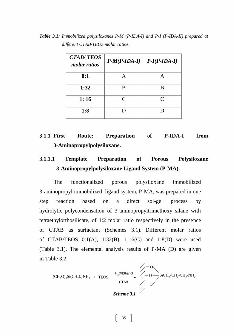
Table 3.1: Immobilized polysiloxanes P-M (P-IDA-I) and P-I (P-IDA-II) prepared at
different CTAB/TEOS molar ratios.
CTAB/ TEOS
molar ratios P-M(P-IDA-I) P-I(P-IDA-I)
0:1 A A
1:32 B B
1: 16 C C
1:8 D D
3.1.1 First Route: Preparation of P-IDA-I from
3-Aminopropylpolysiloxane.
3.1.1.1 Template Preparation of Porous Polysiloxane
3-Aminopropylpolysiloxane Ligand System (P-MA).
The functionalized porous polysiloxane immobilized
3-aminopropyl immobilized ligand system, P-MA, was prepared in one
step reaction based on a direct sol-gel process by
hydrolytic polycondensation of 3-aminopropyltrimethoxy silane with
tetraethylorthosilicate, of 1:2 molar ratio respectively in the presence
of CTAB as surfactant (Schemes 3.1). Different molar ratios
of CTAB/TEOS 0:1(A), 1:32(B), 1:16(C) and 1:8(D) were used
(Table 3.1). The elemental analysis results of P-MA (D) are given
in Table 3.2.
Scheme 3.1
(CH3O)
3Si(CH
2)
3-NH
2
H2O/Ethanol
O
O
O
SiCH2-CH
2-CH
2-NH
2TEOS
CTAB
+
36
O
O
O
Si-CH2-CH
2-CH
2-NH
2
N(Et)3
O
O
O
Si-CH2-CH
2-CH
2
CH2
CH2
C
O
O
O
Si
CH2
CH2
C
-CH2-CH
2-CH
2
ClCH2COOC
2H
5 THF/reflux
CH2CH
3
CH2CH
3
+
C
O
O
O
O
N
HCl
P-MA ethylchloroacetate
P-DIDA-I
P-IDA-I
C
O
O
N
OH
OH
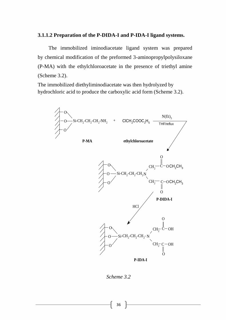
3.1.1.2 Preparation of the P-DIDA-I and P-IDA-I ligand systems.
The immobilized iminodiacetate ligand system was prepared
by chemical modification of the preformed 3-aminopropylpolysiloxane
(P-MA) with the ethylchloroacetate in the presence of triethyl amine
(Scheme 3.2).
The immobilized diethyliminodiacetate was then hydrolyzed by
hydrochloric acid to produce the carboxylic acid form (Scheme 3.2).
Scheme 3.2
37
3.1.2 Second Route: Preparation of P-IDA-II from
3-Iodopropylpolysiloxane.
3.1.2.1 Template Preparation of Porous Polysiloxane 3-Iodopro-
pypolysiloxane Ligand System (P-I).
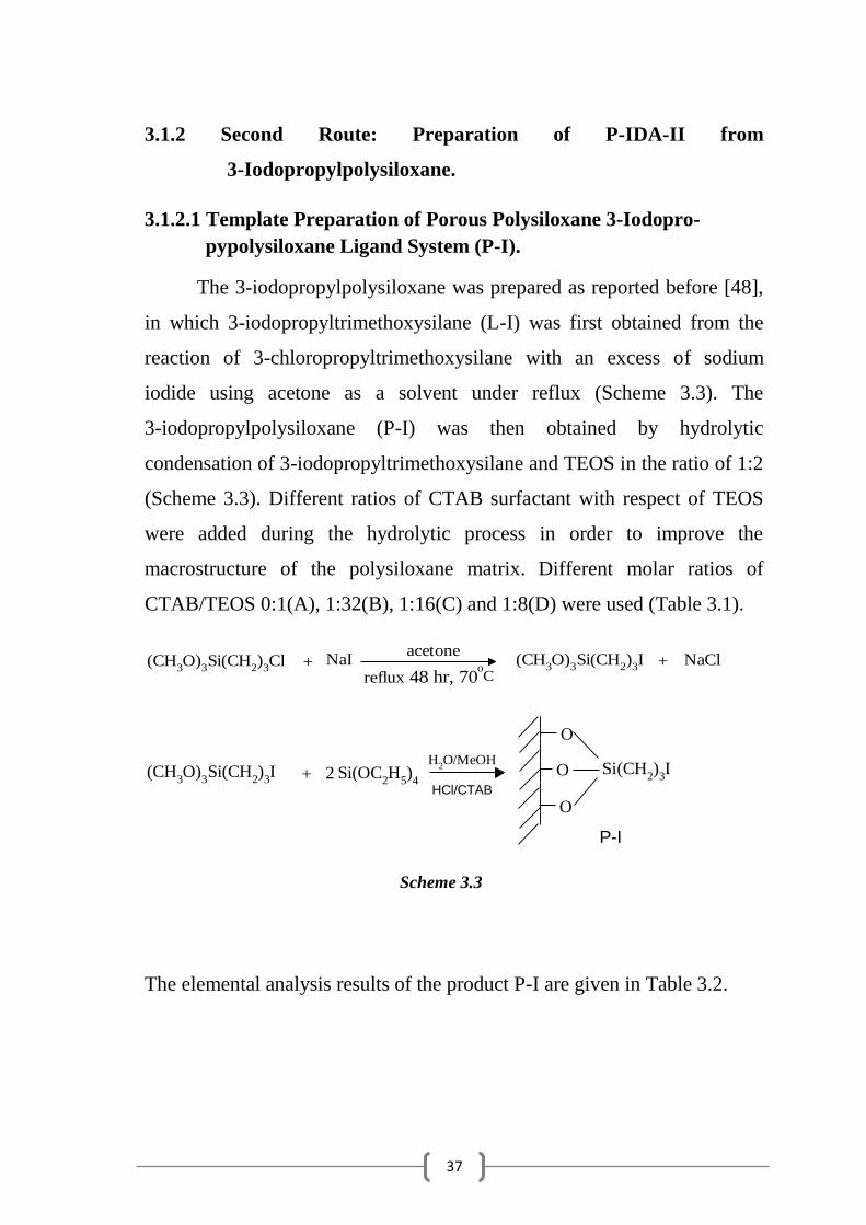
The 3-iodopropylpolysiloxane was prepared as reported before [48],
in which 3-iodopropyltrimethoxysilane (L-I) was first obtained from the
reaction of 3-chloropropyltrimethoxysilane with an excess of sodium
iodide using acetone as a solvent under reflux (Scheme 3.3). The
3-iodopropylpolysiloxane (P-I) was then obtained by hydrolytic
condensation of 3-iodopropyltrimethoxysilane and TEOS in the ratio of 1:2
(Scheme 3.3). Different ratios of CTAB surfactant with respect of TEOS
were added during the hydrolytic process in order to improve the
macrostructure of the polysiloxane matrix. Different molar ratios of
CTAB/TEOS 0:1(A), 1:32(B), 1:16(C) and 1:8(D) were used (Table 3.1).
NaIacetone
(CH3O)
3Si(CH
2)3I + NaCl(CH
3O)
3Si(CH
2)
3Cl
48 hr, 70oC
+reflux
(CH3O)
3Si(CH
2)
3I
O
O
O
Si(CH2)
3ISi(OC
2H
5)
4
H2O/MeOH
+ 2HCl/CTAB
P-I
Scheme 3.3
The elemental analysis results of the product P-I are given in Table 3.2.
38
O
O
O
SiCH2CH
2CH
2-I
CH2
CH2
C
C2H
5
C2H
5
O
O
O
Si-CH2-CH
2-CH
2
CH2
CH2
C
O
O
O
Si
CH2
CH2
C
-CH2-CH
2-CH
2
CH2CH
3
CH2CH
3
N(Et)3
THF/reflux+
C
O
O
O
O
HN
P-I DIDA
C
O
O
O
O
N
HCl
P-DIDA-II
P-IDA-II
C
O
O
N
OH
OH
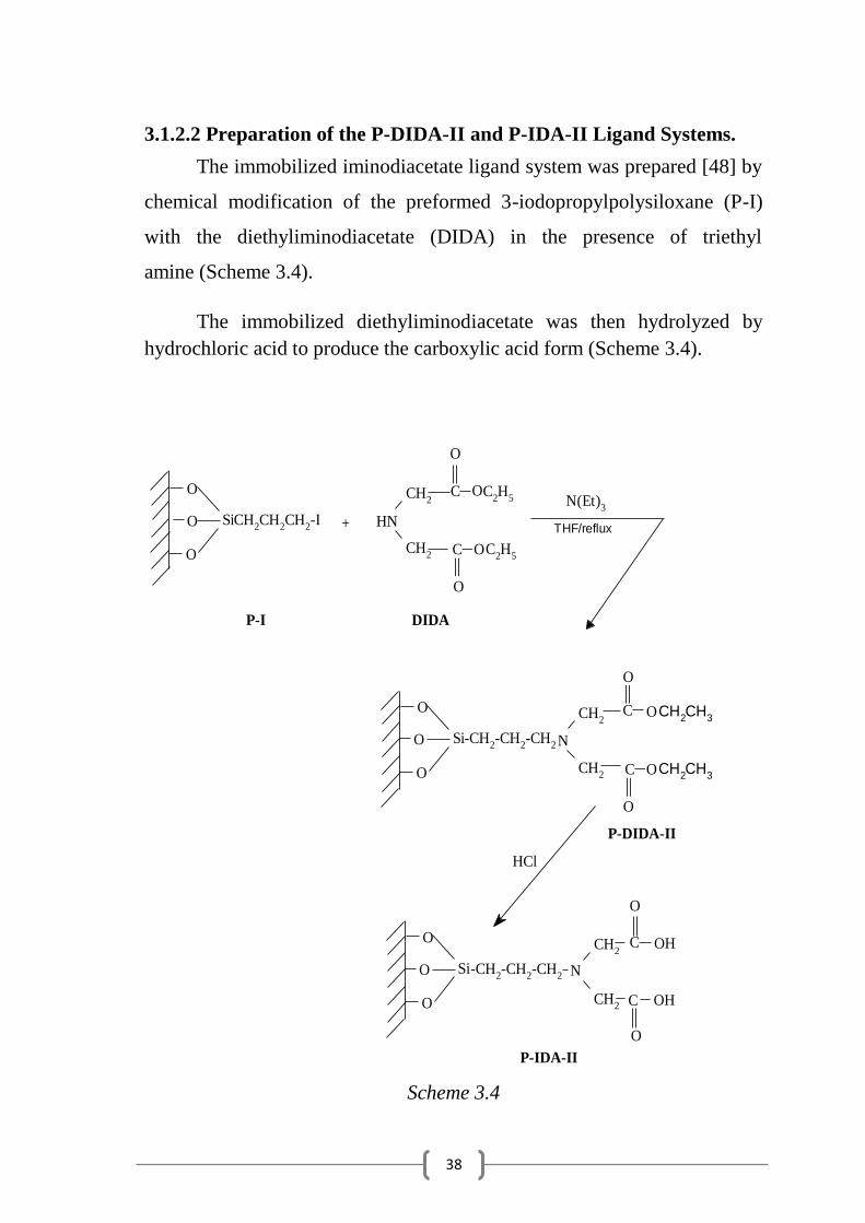
3.1.2.2 Preparation of the P-DIDA-II and P-IDA-II Ligand Systems.
The immobilized iminodiacetate ligand system was prepared [48] by
chemical modification of the preformed 3-iodopropylpolysiloxane (P-I)
with the diethyliminodiacetate (DIDA) in the presence of triethyl
amine (Scheme 3.4).
The immobilized diethyliminodiacetate was then hydrolyzed by
hydrochloric acid to produce the carboxylic acid form (Scheme 3.4).
Scheme 3.4

39
Table 3.2: Elemental analysis data for the polysiloxane-immobilized P-MA,
P-DIDA-I, P-IDA-I, P-I, P-DIDA-II, P-IDA-II(D samples)
polysiloxane
elemental
C%
H%
N%
I%
C/N
C/I
mmol
N/g
mmol
I/g
P-MA Expected 15.65 3.47 6.08 - 3.00 - 4.34 -
found 17.48 3.67 3.61 - 5.60 - 2.57 -
P-DIDA-I
Expected 32.83 4.97 3.48 - 11.00 - 2.48 -
found 21.46 4.28 2.32 - 10.79 - 1.66 -
P-IDA-I Expected 24.27 3.46 4.04 - 7.01 - 2.88 -
found 11.48 3.43 2.13 - 6.28 - 1.52 -
P-I Expected 10.55 1.76 - 37.2 - 3.00 - 2.92
found 9.3 2.26 - 32.3 - 3.04 - 2.54
P-DIDA-II Expected 32.83 4.97 3.48 - 11.00 - 2.48 -
found 21.46 4.28 2.32 - 10.79 - 1.66 -
P-IDA-II Expected 24.27 3.46 4.04 - 7.01 - 2.88 -
found 16.84 3.66 2.29 - 8.57 - 1.63 -
For P-MA and P-I result shown in the table 3.2 it is found that
percentage of C is higher than the expected value in P- MA which is due to
presence of CTAB residue and not all CTAB material extractedcompletely.
But fo P-I it is obvious that the elemental analysis for carbon and iodine are
lower than the expected one. This can be explained by the formation of
small oligomers of low molecular weights as a result of self-condensation
of 3-iodopropyltrimethoxysilane, which were washed away. Self-
condensation of monomers can be enhanced by the different rates of
hydrolysis of the silane agents that are bearing different alkoxy groups
[67].On the other hand the higher percentage of H compared with that of
expected value in each, may be explained due to the presence of
uncondensed hydroxyl groups. This explanation has been confirmed with
29Si NMR results [68,69].

40
For P-MA, The N percentage is lower than expected due to
formation of small oligomers which leached during the washing process in
addition to presence of CTAB residues which increase the molecular
weight of the ligand system. Formation of these small oligomers is
enhanced by the presence of self-base catalyzed amino groups which lead
to rapid gelation, so small amounts of non-cross linked
oligomers are formed [70,71].
It is clear from Table 3.2 that there is lower C and N percentages of
P-DIDA-I and P-DIDA-II than those expected which is probably due to
incomplete reaction of the amino group of P-MA with ethylchloroacetate
when P-DIDA-I was formed and to incomplete substitution reaction of the
iodine present in the polymeric matrix when P-DIDA-II was formed . This
incomplete reaction probably due to steric hindrance of the large DIDA
molecules. Another reason is that only the surface amino or iodo groups
reacted with diethyliminodiacetate ligand and which may block other sites
within the pores or some amino groups are burred into the bulk and are not
accessible for replacement reaction. This explanation has been supported
by electron microscopic studies of previously reported results [48].
Evidences were confirmed by the solid state 13
C NMR and XPS results
discussed latter.
The elemental analysis of P-IDA-I shows that there is a decrease of
carbon percentages due to the hydrolysis of ethoxy groups into the acid
form. This was confirmed by the XPS results discussed later.
41
3.2 FTIR Spectra.
FTIR spectra were obtained for P-MA/CTAB , P-MA, P-DIDA-I and
P-IDA-I, ligand systems (D-samples) and given in (Fig. 3.1) The spectra
show three region of absorption at 3500 – 3000 cm-1
due to ѵ(OH ) or
ѵ(N-H) , 1750 – 1500 cm-1
due to (OH ) or (NH), ѵ(C=O ) or ѵ(CO-N)
and 1200 – 900 cm-1
due to ѵ( Si-O ) vibration. (Fig.3.1(a)) and
(Fig. 3.1(b)) show the spectra of P-MA/CTAB and P-MA where the two
absorptions at 2920 and 1474 cm-1
disappear upon removal of CTAB. The
FTIR spectrum for the immobilized polysiloxane P-DIDA-I (Fig. 3.1(c))
shows the strong absorption at 1740 cm-1
due to ѵ(C=O) vibration of the
ester form (-COOEt). Whereas the spectrum of the immobilized P-IDA-I
(acid form) ligand system ( Fig. 3.1(d)) shows a strong absorption at 1670
cm-1
due to ѵ( C=O ) vibration .

42
Figure 3.1: FTIR spectra for (a)P-MA/CTAB , (b) P-MA, (c) P-DIDA-I and (d) P-IDA-I,
ligand systems (D-samples).
43
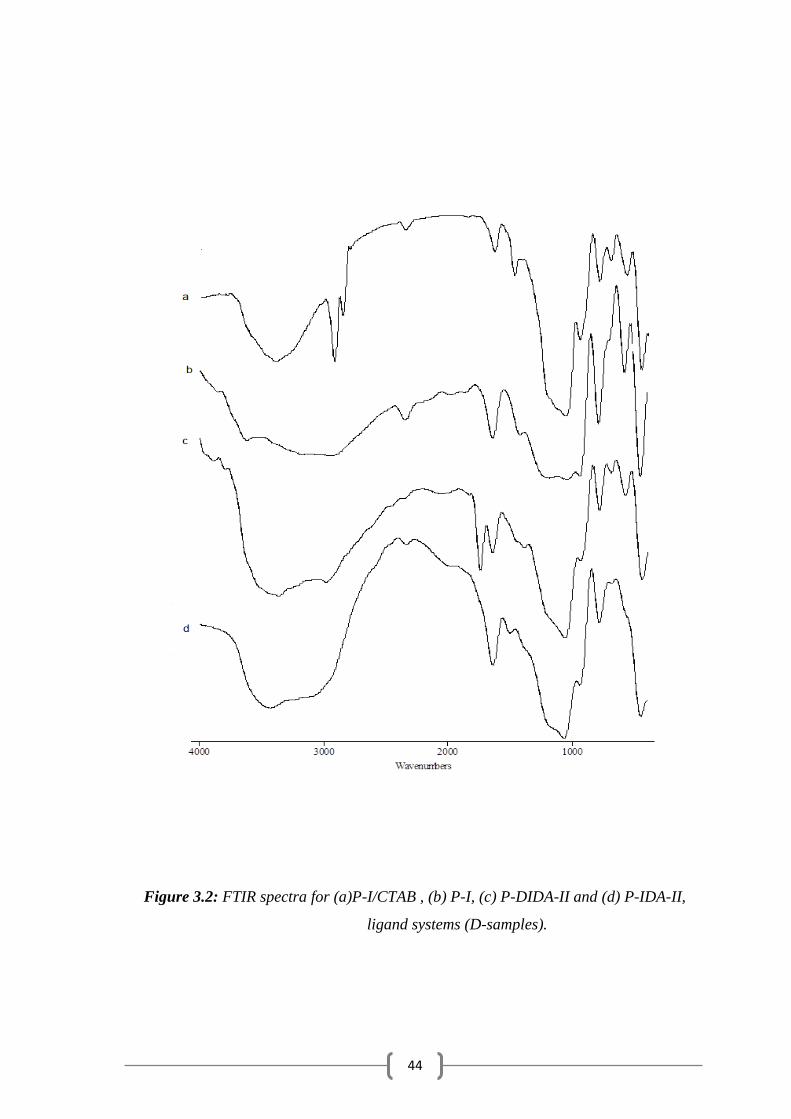
FTIR spectra were obtained also for P-I/CTAB , P-I, P-DIDA-II and
P-IDA-II, ligand systems (D-samples) and given in (Fig. 3.2) The spectra
show three region of absorption at 3500 – 3000 cm-1
due to ѵ(OH ) or ѵ(N-
H) , 1750 – 1500 cm-1
due to (OH ) or (NH), ѵ(C=O ) or ѵ(CO-N) and
1200 – 900 cm-1
due to ѵ( Si-O ) vibration. (Fig.3.1(a)) and
(Fig. 3.1(b)) show the spectra of P-I/CTAB and P-I where the two
absorptions at 2920 and 1474 cm-1
disappear upon removal of CTAB. The
FTIR spectrum for the immobilized polysiloxane P-DIDA-II (Fig. 3.1(c))
shows the strong absorption at 1740 cm-1
due to ѵ(C=O) vibration of the
ester form (-COOEt). Whereas the spectrum of the immobilized P-IDA-II
(acid form) ligand system ( Fig. 3.1(d)) shows a strong absorption at 1670
cm-1
due to ѵ( C=O ) vibration .
44
Figure 3.2: FTIR spectra for (a)P-I/CTAB , (b) P-I, (c) P-DIDA-II and (d) P-IDA-II,
ligand systems (D-samples).
45
3.3 13C NMR Spectra.
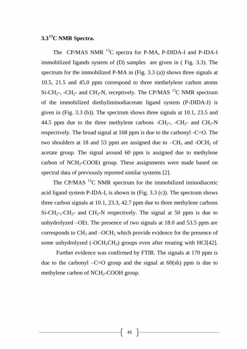
The CP/MAS NMR 13
C spectra for P-MA, P-DIDA-I and P-IDA-I
immobilized ligands system of (D) samples are given in ( Fig. 3.3). The
spectrum for the immobilized P-MA in (Fig. 3.3 (a)) shows three signals at
10.5, 21.5 and 45.0 ppm correspond to three methelylene carbon atoms
Si-CH2-, -CH2- and CH2-N, receptively. The CP/MAS 13
C NMR spectrum
of the immobilized diethyliminodiacetate ligand system (P-DIDA-I) is
given in (Fig. 3.3 (b)). The spectrum shows three signals at 10.1, 23.5 and
44.5 ppm due to the three methylene carbons -CH2-, -CH2- and CH2-N
respectively. The broad signal at 168 ppm is due to the carbonyl -C=O. The
two shoulders at 18 and 53 ppm are assigned due to –CH3 and -OCH2 of
acetate group. The signal around 60 ppm is assigned due to methylene
carbon of NCH2-COOEt group. These assignments were made based on
spectral data of previously reported similar systems [2].
The CP/MAS 13
C NMR spectrum for the immobilized iminodiacetic
acid ligand system P-IDA-I, is shown in (Fig. 3.3 (c)). The spectrum shows
three carbon signals at 10.1, 23.3, 42.7 ppm due to three methylene carbons
Si-CH2-,-CH2- and CH2-N respectively. The signal at 50 ppm is due to
unhydrolyzed –OEt. The presence of two signals at 18.0 and 53.5 ppm are
corresponds to CH3 and –OCH2 which provide evidence for the presence of
some unhydrolyzed (-OCH2CH3) groups even after treating with HCl[42].
Further evidence was confirmed by FTIR. The signals at 170 ppm is
due to the carbonyl –C=O group and the signal at 60(sh) ppm is due to
methylene carbon of NCH2-COOH group.
46
Figure 3.3: CP/MAS NMR 13
C spectra for (a) P-MA, (b) P-DIDA-I and
(c) P-IDA-I immobilized ligand systems of (D- samples).
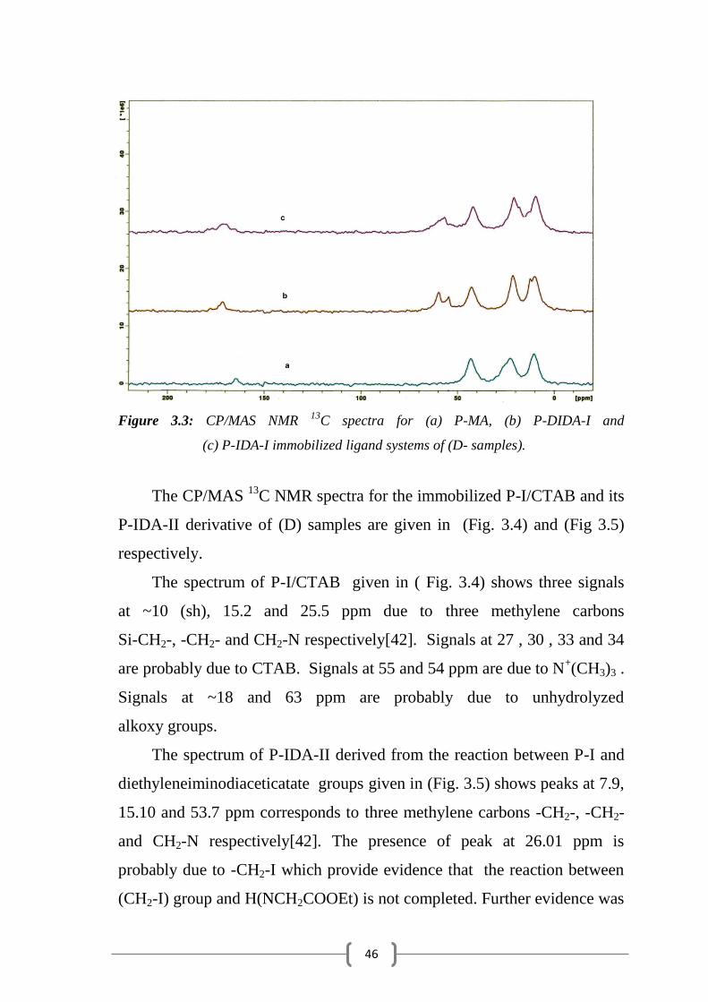
The CP/MAS 13
C NMR spectra for the immobilized P-I/CTAB and its
P-IDA-II derivative of (D) samples are given in (Fig. 3.4) and (Fig 3.5)
respectively.
The spectrum of P-I/CTAB given in ( Fig. 3.4) shows three signals
at ~10 (sh), 15.2 and 25.5 ppm due to three methylene carbons
Si-CH2-, -CH2- and CH2-N respectively[42]. Signals at 27 , 30 , 33 and 34
are probably due to CTAB. Signals at 55 and 54 ppm are due to N+(CH3)3 .
Signals at ~18 and 63 ppm are probably due to unhydrolyzed
alkoxy groups.
The spectrum of P-IDA-II derived from the reaction between P-I and
diethyleneiminodiaceticatate groups given in (Fig. 3.5) shows peaks at 7.9,
15.10 and 53.7 ppm corresponds to three methylene carbons -CH2-, -CH2-
and CH2-N respectively[42]. The presence of peak at 26.01 ppm is
probably due to -CH2-I which provide evidence that the reaction between
(CH2-I) group and H(NCH2COOEt) is not completed. Further evidence was

47
confirmed by XPS results. The signals at 18 and 63 ppm are due to
unhydrolyzed –OEt groups.
Figure 3.4: CP/MAS NMR 13
C spectra for the immobilized P-I/CTAB system of
(D- samples).
Figure 3.5: CP/MAS NMR 13
C spectra for the of P-IDA-II system of (D- samples).
48
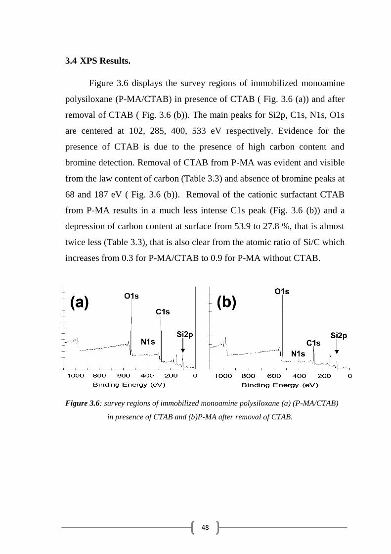
3.4 XPS Results.
Figure 3.6 displays the survey regions of immobilized monoamine
polysiloxane (P-MA/CTAB) in presence of CTAB ( Fig. 3.6 (a)) and after
removal of CTAB ( Fig. 3.6 (b)). The main peaks for Si2p, C1s, N1s, O1s
are centered at 102, 285, 400, 533 eV respectively. Evidence for the
presence of CTAB is due to the presence of high carbon content and
bromine detection. Removal of CTAB from P-MA was evident and visible
from the law content of carbon (Table 3.3) and absence of bromine peaks at
68 and 187 eV ( Fig. 3.6 (b)). Removal of the cationic surfactant CTAB
from P-MA results in a much less intense C1s peak (Fig. 3.6 (b)) and a
depression of carbon content at surface from 53.9 to 27.8 %, that is almost
twice less (Table 3.3), that is also clear from the atomic ratio of Si/C which
increases from 0.3 for P-MA/CTAB to 0.9 for P-MA without CTAB.
Figure 3.6: survey regions of immobilized monoamine polysiloxane (a) (P-MA/CTAB)
in presence of CTAB and (b)P-MA after removal of CTAB.
49
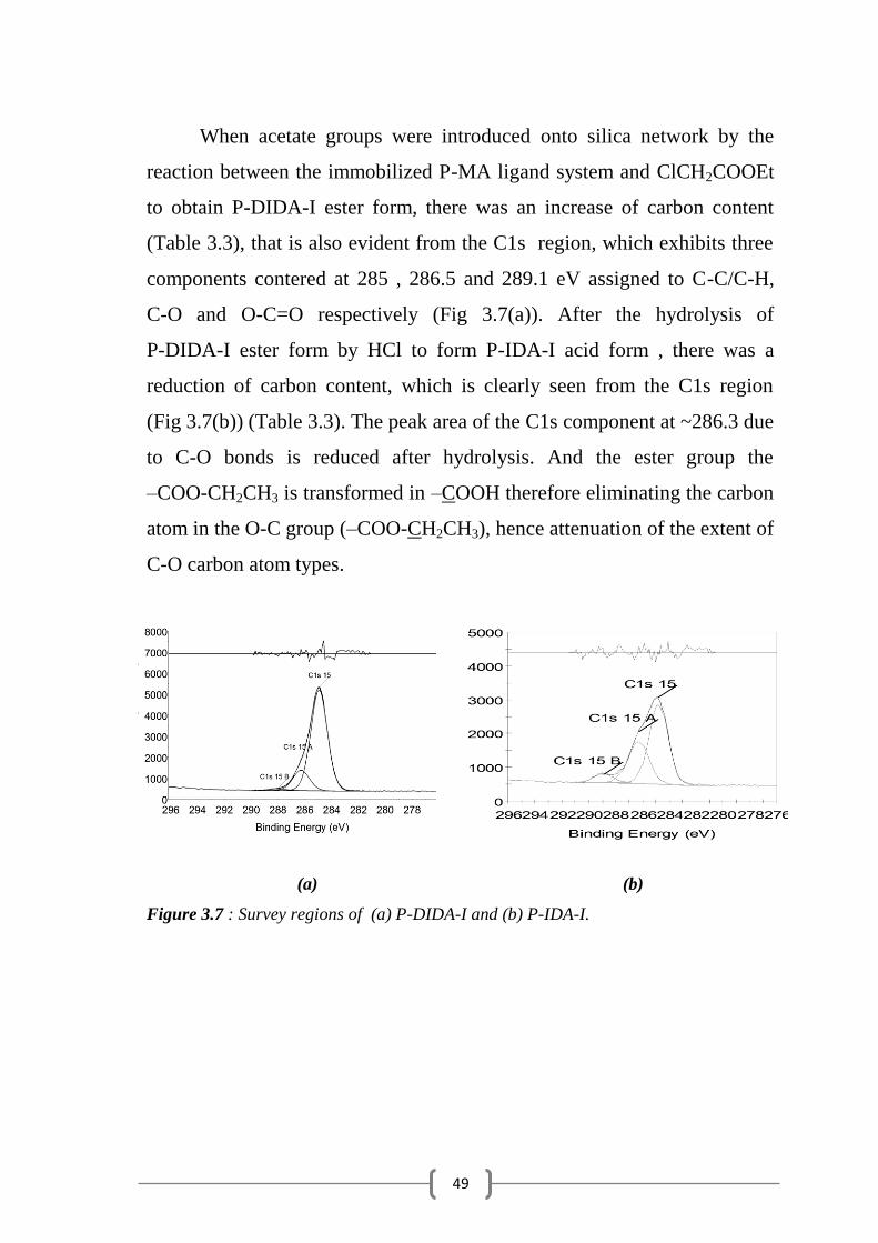
When acetate groups were introduced onto silica network by the
reaction between the immobilized P-MA ligand system and ClCH2COOEt
to obtain P-DIDA-I ester form, there was an increase of carbon content
(Table 3.3), that is also evident from the C1s region, which exhibits three
components contered at 285 , 286.5 and 289.1 eV assigned to C-C/C-H,
C-O and O-C=O respectively (Fig 3.7(a)). After the hydrolysis of
P-DIDA-I ester form by HCl to form P-IDA-I acid form , there was a
reduction of carbon content, which is clearly seen from the C1s region
(Fig 3.7(b)) (Table 3.3). The peak area of the C1s component at ~286.3 due
to C-O bonds is reduced after hydrolysis. And the ester group the
–COO-CH2CH3 is transformed in –COOH therefore eliminating the carbon
atom in the O-C group (–COO-CH2CH3), hence attenuation of the extent of
C-O carbon atom types.
(a) (b)
Figure 3.7 : Survey regions of (a) P-DIDA-I and (b) P-IDA-I.
50
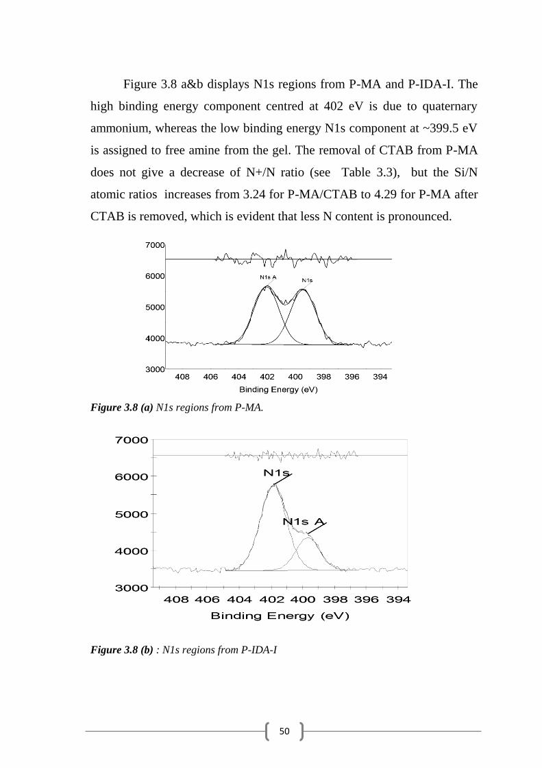
Figure 3.8 a&b displays N1s regions from P-MA and P-IDA-I. The
high binding energy component centred at 402 eV is due to quaternary
ammonium, whereas the low binding energy N1s component at ~399.5 eV
is assigned to free amine from the gel. The removal of CTAB from P-MA
does not give a decrease of N+/N ratio (see Table 3.3), but the Si/N
atomic ratios increases from 3.24 for P-MA/CTAB to 4.29 for P-MA after
CTAB is removed, which is evident that less N content is pronounced.
Figure 3.8 (a) N1s regions from P-MA.
Figure 3.8 (b) : N1s regions from P-IDA-I
51
0 200 400 600 800 1000
0
50k
100k
150k
200k
I3d
N1s
O1s
C1s
Si2p
(b)
(a)
I (c
ps)
Binding energy (eV)
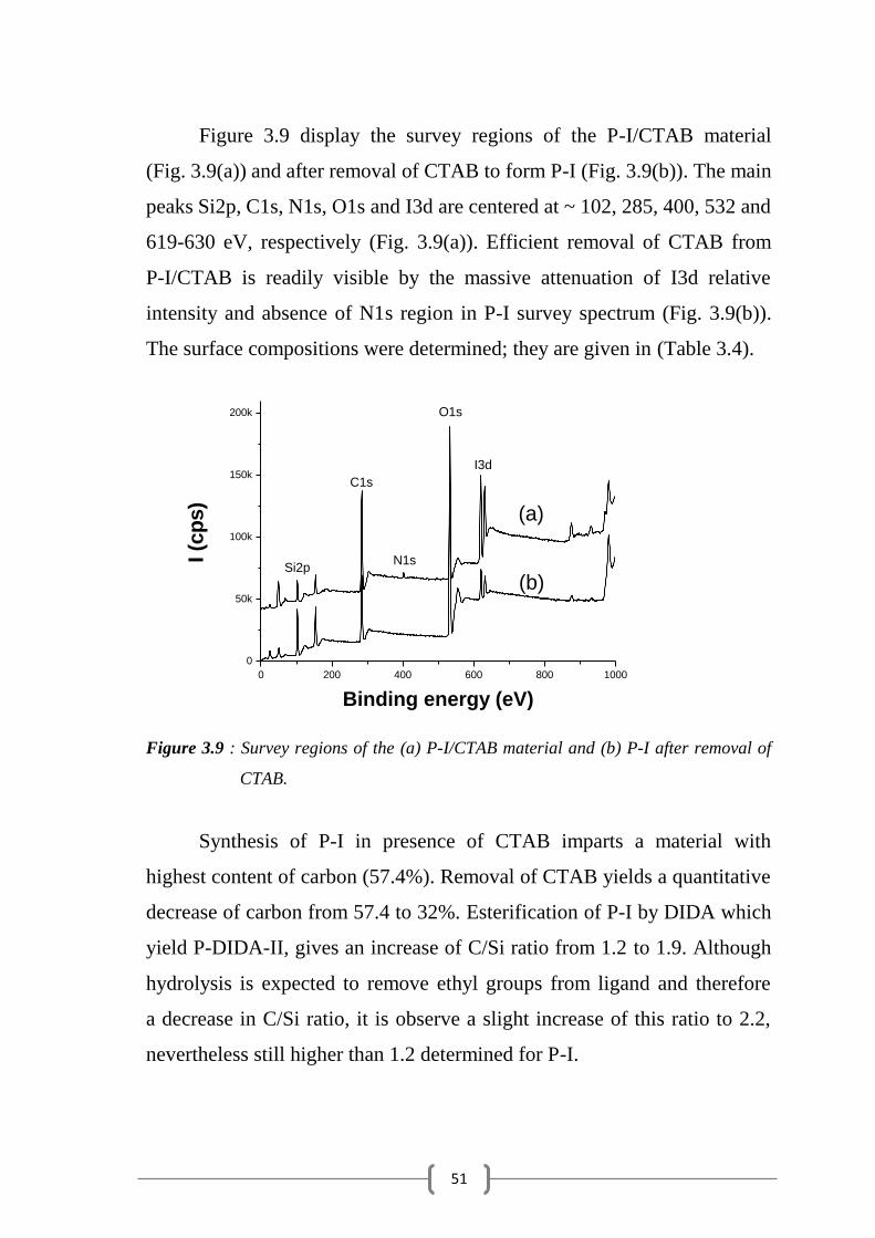
Figure 3.9 display the survey regions of the P-I/CTAB material
(Fig. 3.9(a)) and after removal of CTAB to form P-I (Fig. 3.9(b)). The main
peaks Si2p, C1s, N1s, O1s and I3d are centered at ~ 102, 285, 400, 532 and
619-630 eV, respectively (Fig. 3.9(a)). Efficient removal of CTAB from
P-I/CTAB is readily visible by the massive attenuation of I3d relative
intensity and absence of N1s region in P-I survey spectrum (Fig. 3.9(b)).
The surface compositions were determined; they are given in (Table 3.4).
Figure 3.9 : Survey regions of the (a) P-I/CTAB material and (b) P-I after removal of
CTAB.
Synthesis of P-I in presence of CTAB imparts a material with
highest content of carbon (57.4%). Removal of CTAB yields a quantitative
decrease of carbon from 57.4 to 32%. Esterification of P-I by DIDA which
yield P-DIDA-II, gives an increase of C/Si ratio from 1.2 to 1.9. Although
hydrolysis is expected to remove ethyl groups from ligand and therefore
a decrease in C/Si ratio, it is observe a slight increase of this ratio to 2.2,
nevertheless still higher than 1.2 determined for P-I.

52
280 285 290 295
0
10k
20k
30k
COOC2H
5
COOH
C-C/C-H
C-O
(c)
(b)
(a)
I (c
ps)
Binding energy (eV)
The high resolution C1s regions from P-I, P-DIDA-II, P-IDA-II are
displayed in (Fig. 3.10) P-I has a simple structure (Fig. 3.10 (a)) that is
very well distinguished from that of P-DIDA-II (Fig. 3.10 (b)) as a result
of reaction of P-I with diethyliminodiacetate. The C1s region form P-DIDA
exhibits indeed three components centered at 285, 286.5 and 289.1eV
(in the 1:0.52:0.07 ratio) assigned to C-C/C-H, C-O and O-C=O,
respectively (Fig. 3.10 (b)). Upon hydrolysis of P-DIDA-II, the sol gel
material P-IDA-II was obtained. Effective hydrolysis gave three similar
components centered at 285, 286.4 and 288.8 eV (in the 1:0.35:0.05 ratio),
however with significantly lower relative intensity for the C-O bond
component centered at 286.4 eV (Fig. 3.10 (c)). Indeed the transformation
of –N(COO-CH2CH3)2 into –N(COOH)2 induces the loss of the alkoxy
O-CH2CH3 and thus the attenuation of C1s component due to O-CH2 band.
Figure 3.10 : High resolution C1s regions from (a) P-I, (b) P-DIDA-II and
(c) P-IDA-II.
53
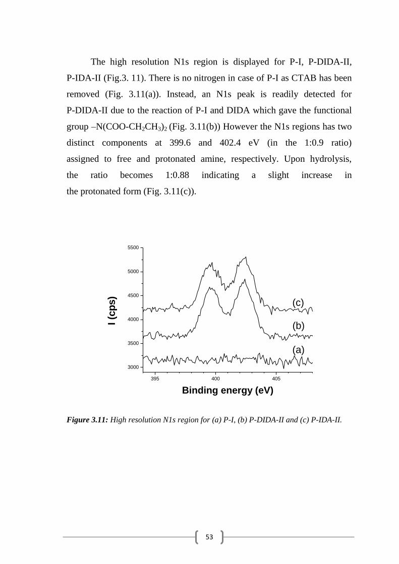
The high resolution N1s region is displayed for P-I, P-DIDA-II,
P-IDA-II (Fig.3. 11). There is no nitrogen in case of P-I as CTAB has been
removed (Fig. 3.11(a)). Instead, an N1s peak is readily detected for
P-DIDA-II due to the reaction of P-I and DIDA which gave the functional
group –N(COO-CH2CH3)2 (Fig. 3.11(b)) However the N1s regions has two
distinct components at 399.6 and 402.4 eV (in the 1:0.9 ratio)
assigned to free and protonated amine, respectively. Upon hydrolysis,
the ratio becomes 1:0.88 indicating a slight increase in
the protonated form (Fig. 3.11(c)).
Figure 3.11: High resolution N1s region for (a) P-I, (b) P-DIDA-II and (c) P-IDA-II.
395 400 405
3000
3500
4000
4500
5000
5500
(b)
(c)
(a)
I (c
ps)
Binding energy (eV)
54
Table 3.3: XPS data and % surface composition of P-MA and its derivatives.
Table 3.4: XPS data and % surface composition of P-I and its derivatives.
Polysiloxane
Element Si C O N I Cl N/Si
Core-line Si2p
102
C1s
285
O1s
532
N1s
399.5
I3d Cl2p 1:9
P-I/CTAB %Composition 15.1 57.4 22.4 2.0 3.0 -
P-I %Composition 25.9 32.0 40.0 - 1.5 0.6
P-DIDA-II %Composition 20.9 40.6 34.4 2.5 1.2 0.4
P-IDA-II %Composition 20.3 44.5 32.2 2.2 - 0.8
Polysiloxane
Element Si C O N + N+ Cl N/Si
Core-line Si2p
102
C1s
285
O1s
532
N1s
399.5
Cl2p
P-MA/CTAB %Composition 16.2 53.9 23.9 5.1 0.95
P-MA %Composition 25.0 27.2 39.2 5.85 1.7
P-DIDA-I %Composition 20.7 35.1 35.5 5.0 3.1
P-IDA-I %Composition 21.7 39.5 32.6 3.7 2.9
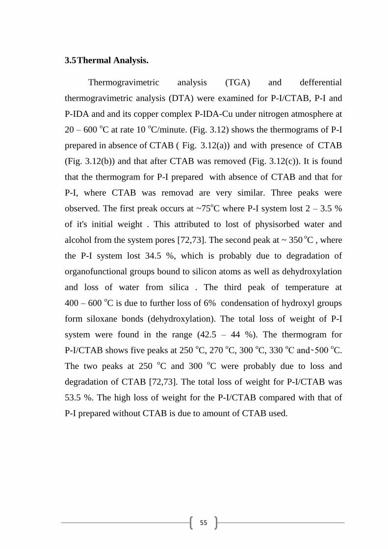
55
3.5 Thermal Analysis.
Thermogravimetric analysis (TGA) and defferential
thermogravimetric analysis (DTA) were examined for P-I/CTAB, P-I and
P-IDA and and its copper complex P-IDA-Cu under nitrogen atmosphere at
20 – 600 oC at rate 10
oC/minute. (Fig. 3.12) shows the thermograms of P-I
prepared in absence of CTAB ( Fig. 3.12(a)) and with presence of CTAB
(Fig. 3.12(b)) and that after CTAB was removed (Fig. 3.12(c)). It is found
that the thermogram for P-I prepared with absence of CTAB and that for
P-I, where CTAB was removad are very similar. Three peaks were
observed. The first preak occurs at ~75oC where P-I system lost 2 – 3.5 %
of it's initial weight . This attributed to lost of physisorbed water and
alcohol from the system pores [72,73]. The second peak at ~ 350 oC , where
the P-I system lost 34.5 %, which is probably due to degradation of
organofunctional groups bound to silicon atoms as well as dehydroxylation
and loss of water from silica . The third peak of temperature at
400 – 600 oC is due to further loss of 6% condensation of hydroxyl groups
form siloxane bonds (dehydroxylation). The total loss of weight of P-I
system were found in the range (42.5 – 44 %). The thermogram for
P-I/CTAB shows five peaks at 250 oC, 270
oC, 300
oC, 330
oC and 500
oC.
The two peaks at 250 oC and 300
oC were probably due to loss and
degradation of CTAB [72,73]. The total loss of weight for P-I/CTAB was
53.5 %. The high loss of weight for the P-I/CTAB compared with that of
P-I prepared without CTAB is due to amount of CTAB used.
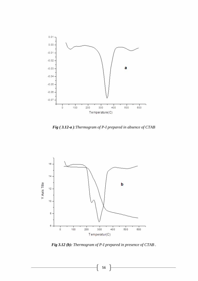
56
Fig ( 3.12-a ):Thermogram of P-I prepared in absence of CTAB
Fig 3.12 (b): Thermogram of P-I prepared in presence of CTAB .

57
Fig 3.12 (c): Thermogram of P-I after CTAB was removed.
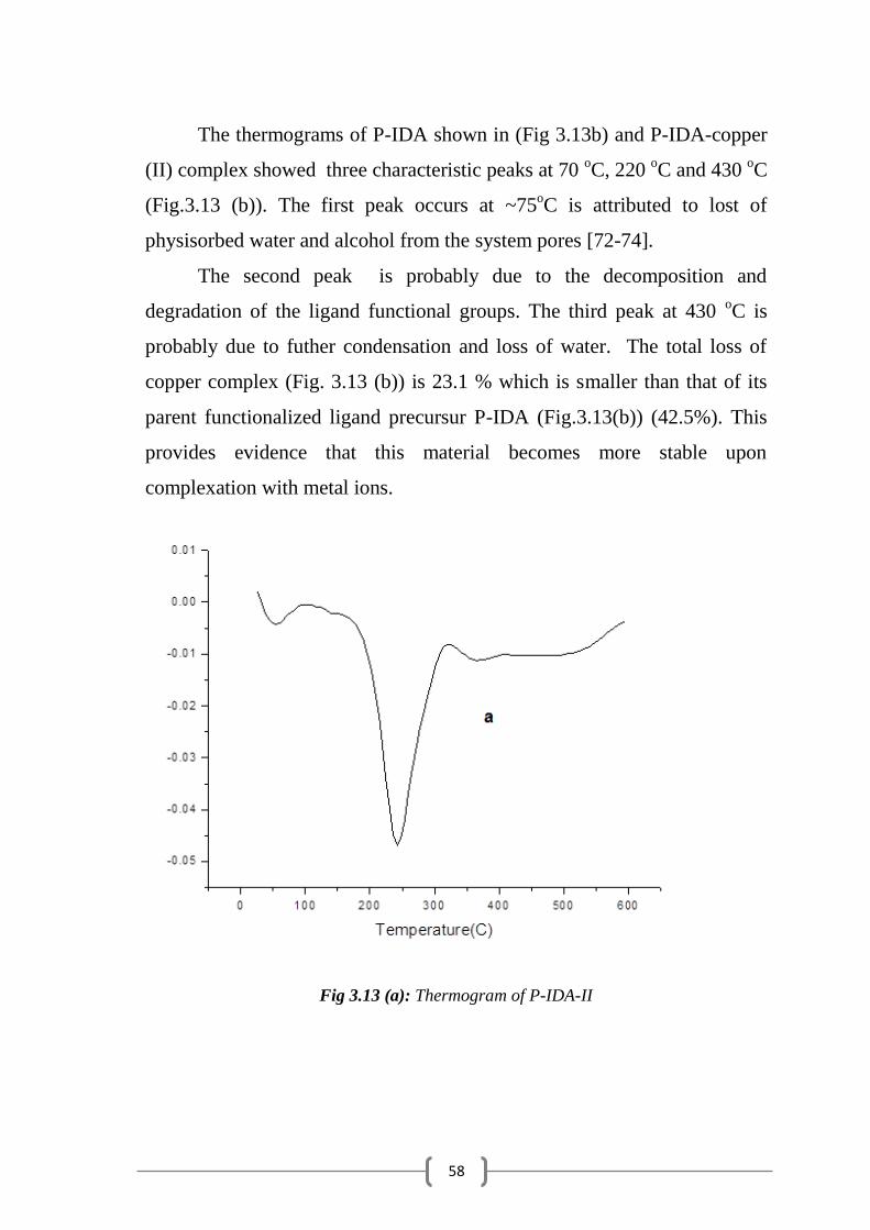
58
The thermograms of P-IDA shown in (Fig 3.13b) and P-IDA-copper
(II) complex showed three characteristic peaks at 70 oC, 220
oC and 430
oC
(Fig.3.13 (b)). The first peak occurs at ~75oC is attributed to lost of
physisorbed water and alcohol from the system pores [72-74].
The second peak is probably due to the decomposition and
degradation of the ligand functional groups. The third peak at 430 oC is
probably due to futher condensation and loss of water. The total loss of
copper complex (Fig. 3.13 (b)) is 23.1 % which is smaller than that of its
parent functionalized ligand precursur P-IDA (Fig.3.13(b)) (42.5%). This
provides evidence that this material becomes more stable upon
complexation with metal ions.
Fig 3.13 (a): Thermogram of P-IDA-II
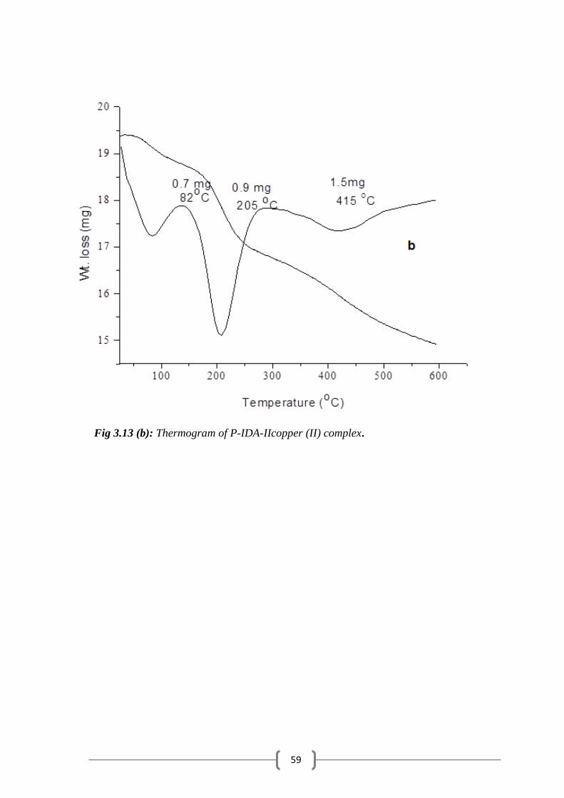
59
Fig 3.13 (b): Thermogram of P-IDA-IIcopper (II) complex.

60
3.6 Metal Uptake Capacity.
3.6.1 Effect of Surfactant Concentration.
The metal ion uptake capacity was determined by batch method by
mixing the P-IDA–I or P-IDA-II polysiloxane ligand systems with
buffered solutions of copper metal ion. Measurements were carried out at
room temperature, pH 6 and 72 hours uptake time. Table 3.5 dipicted the
metal uptake capacity at different concentartions of surfactants with
respect to TEOS. It is shown that P-IDA-II showed higher metal uptake
capcaity than P-IDA-I. The highest metal uptake capacity of both
immobilized ligand system is shown in case of 1:8, surfactant :TEOS molar
ratio respicively which attibuted to presence of a well porous mesostructure
that caused by surfactant template synthesis.
Table 3.5: Copper uptake by P-IDA-I and P-IDA-II, pH=6, T=25 oC and =72 hrs.
CTAB/ TEOS * Type P-IDA-I P-IDA-II
0:1 A 0.230 0.630
1:32 B 0.382 1.031
1: 16 C 0.606 1.172
1:8 D 0.657 1.298
*molar ratio.
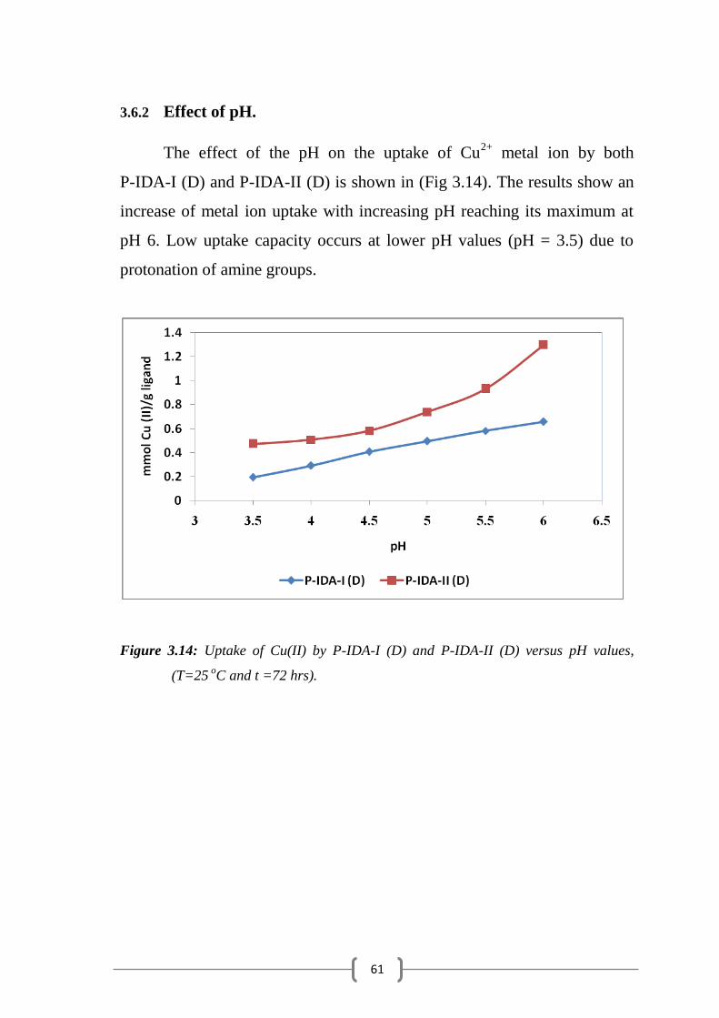
61
3.6.2 Effect of pH.
The effect of the pH on the uptake of Cu2+
metal ion by both
P-IDA-I (D) and P-IDA-II (D) is shown in (Fig 3.14). The results show an
increase of metal ion uptake with increasing pH reaching its maximum at
pH 6. Low uptake capacity occurs at lower pH values (pH = 3.5) due to
protonation of amine groups.
Figure 3.14: Uptake of Cu(II) by P-IDA-I (D) and P-IDA-II (D) versus pH values,
(T=25 o
C and t =72 hrs).

62
0
0.2
0.4
0.6
0.8
1
1.2
1.4
1.6
0 20 40 60 80
mm
ol C
u(I
I)/g
Lig
and
Tempretuer oC
3.6.3 Effect of Temperature on Metl Uptake of P-IDA-I.
The influence of temperature on Cu metal ions chemisorption by
P-IDA-I from aqueous solutions was investigated at different temperatures
(25-70) oC, at pH 6 by batch method. The results are presented in
(Figure 3.15) It is observed that the amount of metal ions extracted
increases with increasing of temperature. The curve indicates higher
affinity of the sorbent toward Cu metal ion by increasing of temperature
suggesting higher endothermic effect and increasing of mobility and
diffusion rate of this metal ion within the polysiloxane particles.
Fig 3.15: Uptake of Cu(II) by P-IDA-I (D) versus temperature.
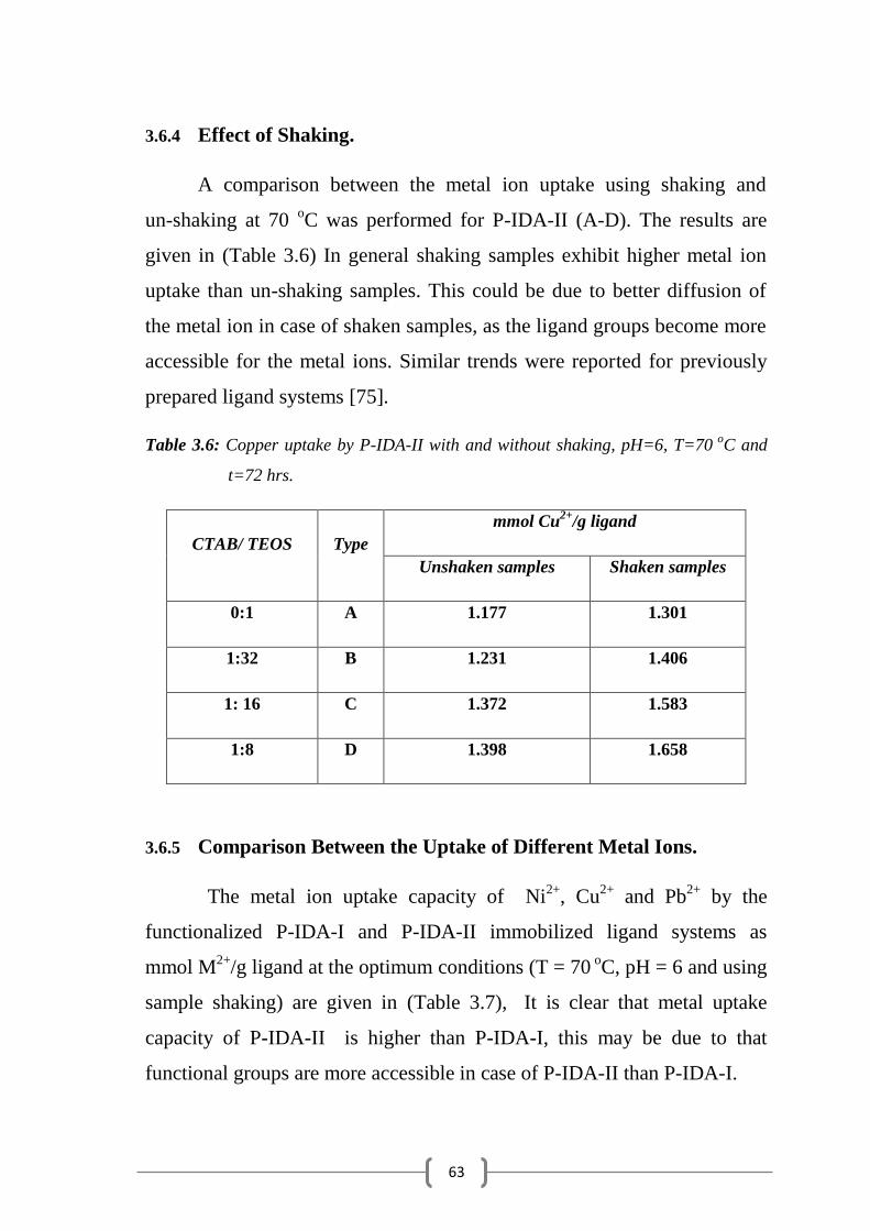
63
3.6.4 Effect of Shaking.
A comparison between the metal ion uptake using shaking and
un-shaking at 70 oC was performed for P-IDA-II (A-D). The results are
given in (Table 3.6) In general shaking samples exhibit higher metal ion
uptake than un-shaking samples. This could be due to better diffusion of
the metal ion in case of shaken samples, as the ligand groups become more
accessible for the metal ions. Similar trends were reported for previously
prepared ligand systems [75].
Table 3.6: Copper uptake by P-IDA-II with and without shaking, pH=6, T=70 o
C and
t=72 hrs.
mmol Cu2+
/g ligand
Type CTAB/ TEOS
Shaken samples Unshaken samples
1.301 1.177 A 0:1
1.406 1.231 B 1:32
1.583 1.372 C 1: 16
1.658 1.398 D 1:8
3.6.5 Comparison Between the Uptake of Different Metal Ions.
The metal ion uptake capacity of Ni2+
, Cu2+
and Pb2+
by the
functionalized P-IDA-I and P-IDA-II immobilized ligand systems as
mmol M2+
/g ligand at the optimum conditions (T = 70 oC, pH = 6 and using
sample shaking) are given in (Table 3.7), It is clear that metal uptake
capacity of P-IDA-II is higher than P-IDA-I, this may be due to that
functional groups are more accessible in case of P-IDA-II than P-IDA-I.

64
It is clear that the uptake of metal ions increases in the order:
Cu2+
Ni2+
Pb2+
Table 3.7: Comparison between the uptake of different metal ions, T = 70 o
C, pH = 6,
t=72 hrs and using sample shaking.
mmol M (II)/g ligand
(P-IDA-II)
mmol M (II)/g ligand
(P-IDA-I)
Type
CTAB/
TEOS Cu (II) Ni (II) Pb (II) Cu (II) Ni (II) Pb (II)
1.301 0.358 0.072 1.263 0.134 0.027 A 0:1
1.406 0.37 0.141 1.304 0.230 0.074 B 1:32
1.583 0.40 0.186 1.397 0.345 0.112 C 1:16
1.658 0.553 0.338 1.509 0.399 0.241 D 1:8
3.6.6 Effect of Shaking Time
Measurements of metal uptake capacity of both P-IDA-I and
P-IDA-II for different metal ions (Ni2+
, Cu2+
and Pb2+
) were carried out at
different time intervals at the optimum conditions (T = 70 0
C, pH = 6 and
using shaking samples of 1:8 CTAB/TEOS mole ratio). The results are
given in Figures 3.(16-18). It is shown that the metal ion uptake is
increased as a function of shaking time and reached equilibrium nearly
after 24 hours where maximum uptake is obtained.
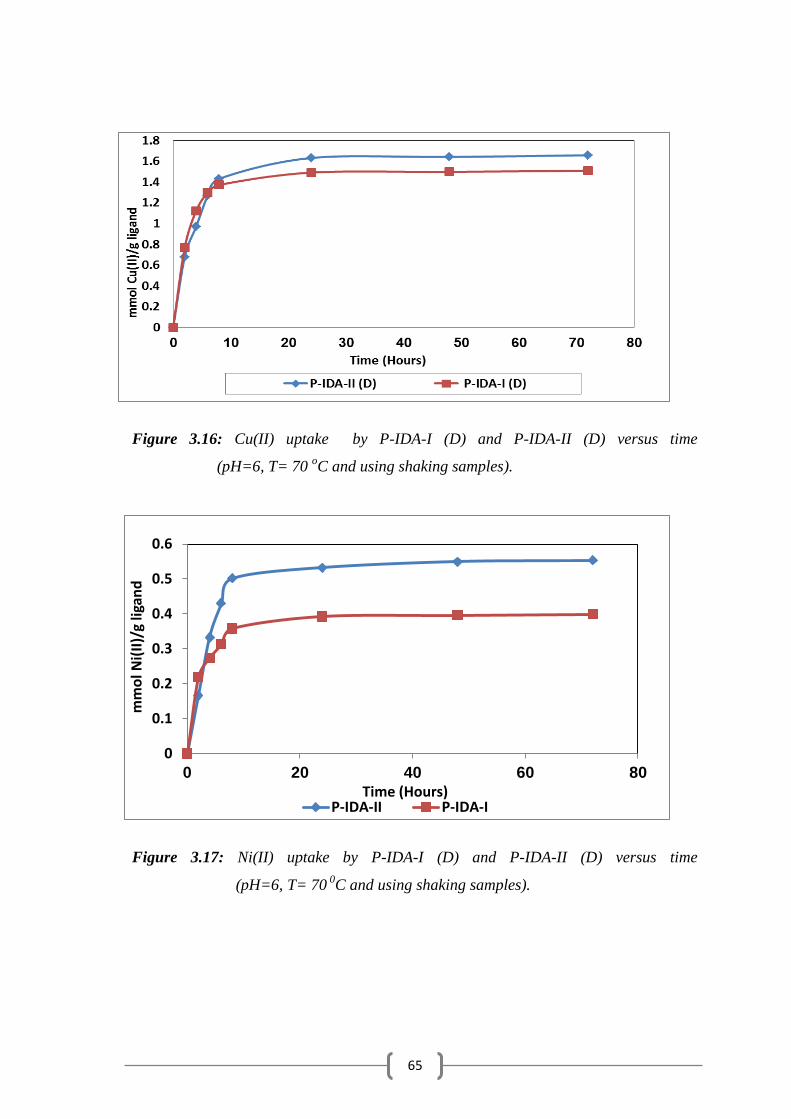
65
0
0.1
0.2
0.3
0.4
0.5
0.6
0 20 40 60 80
mm
ol N
i(II
)/g
ligan
d
Time (Hours) P-IDA-II P-IDA-I
Figure 3.16: Cu(II) uptake by P-IDA-I (D) and P-IDA-II (D) versus time
(pH=6, T= 70 oC and using shaking samples).
Figure 3.17: Ni(II) uptake by P-IDA-I (D) and P-IDA-II (D) versus time
(pH=6, T= 70 0
C and using shaking samples).
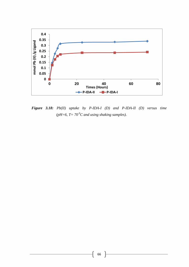
66
0
0.05
0.1
0.15
0.2
0.25
0.3
0.35
0.4
0 20 40 60 80
mm
ol P
b (
II)
/g L
igan
d
Times (Hours)
P-IDA-II P-IDA-I
Figure 3.18: Pb(II) uptake by P-IDA-I (D) and P-IDA-II (D) versus time
(pH=6, T= 70 0
C and using shaking samples).

67
Conclusion
In this study insoluble iminodiacetic acid polysiloxane immobilized
ligand systems, have been prepared by template sol-gel method in presence
of CTAB surfactant.
The sol-gel process is summarized in hydrolytic polycondensation of
TEOS and an appropriate silane coupling agent. The
3-aminopropylpolysiloxane and 3-iodopropylpolysiloxane were primarily
prepared by this method followed by systematic chemical modification to
obtain the desired iminodiaacetic acid functionalized ligand systems in two
routes.
In the first route preparation was achieved by modification of
3-aminopropyllpolysilocxane with ethylchloroacetate followed by
hydrolysis of the ethoxy groups. The second route was achieved by the
reaction of 3-iodopropylpolysiloxane with diethyliminodiacetate followed
by hydrolysis of the ethoxy groups.
These polysiloxane immobilized ligand systems were well
characterized by a variety of physical techniques.
FTIR provided strong qualitative evidences about the functional
groups of the immobilized ligands.
High-resolution 13
C CP-MAS NMR provided essential information
on the structural nature of the pendent ligand groups.
XPS technique provided valuable information about the surface
chemical composition for these immobilized ligand systems.
TGA and TDG thermal analysis confirmed that these immobilized
ligand systems are highly thermal stable even at high temperatures
(up to 250 0C). Very High temperatures disrupt the polysiloxane matrix and
cause pyrolysis and modification of the structural properties.
68
Elemental analysis provided the exact content of the functionalized
ligand groups that attached to the immobilized ligand systems.
These immobilized ligand systems exhibit high potential for
preconcentration of divalent metal ions (Ni2+
, Cu2+
and Pb2+
)
from aqueous solutions.
The optimum experimental conditions that studied showed that
maximum uptake could be attained at pH 6 for 48 hours shaking at 70oC.
69
REFERENCES
1- J. O. Duruibe, M. O. C. Ogwuegbu and J. N. Egwurugwu, Heavy metal
pollution and human biotoxic effects. Int. J. Phys. Sci. 2007, 2 (5),
112-118.
2- M.A. Momodu and C.A. Anyakora., Heavy Metal Contamination of
Ground Water: The Surulere Case Study., Res J Environ Earth Sci.,
2010, 2(1), 39-43.
3- L. Malachowski, J. L. Stair, and J. A. Holcombe, Immobilized
peptides/amino acids on solid supports for metal remediation, Pure
Appl. Chem., 2004, 76 (4), 777–787.
4- N.M. El-Ashgar, Extraction and Preconcentration Capacity of
Bifunctionalized Diamine-Thiol Polysiloxane Immobilized Ligand
System Towards Some Divalent Cations. J. Iran. Chem. Soc., 2008,
6(4), 823-830.
5- S. K. Muzyed, Heavy Metal Concentrations in Commercially
Available Fishes in Gaza Strip Markets, M.Sc. thesis, Islamic
University, 2011.
6- K. Mortazavi, M. Ghaedi, M. Roosta and M. Montazerozohori.,
Chemical functionalization of silica gel with 2-((3-silylpropylimino)
methyl) phenol (SPIMP) and its application for solid phase
extraction and preconcentration of Fe (III), Pb (II), Cu (II), Ni (II),
Co (II) and Zn (II) Ions., Indian J.Sci.Technol., 2012, 5(1), ISSN:
0974- 6846.
7- R. K. Sharma., Design, synthesis, and application of chelating
polymers for separation and determination of trace and toxic metal
ions. A green analytical method. Pure Appl. Chem., 2001, 73 (1),
181–186.
70
8- J. L. Stair, Synthesis and Characterization of Short Chain Peptides
for use in Metal Remediation and Preconcentration,
Ph.D. thesis 2006.
9- M. A. Hughes, The Structure Function Relationship of Silica
Polyamine Composites, PhD Thesis, ProQuest Informayion
and Learning Company, 2007
10- D. W. Hall, J. A. Sandrin, and R. E. McBride, An overview of solvent
extraction treatment technologies. Environmental Progress, 1990,
9(2), 98-105.
11- K. E.Geckeler, and K. Volchek, Removal of Hazardous Substances
from Water Using Ultrafiltration in Conjunction with Soluble
Polymers. Environ. Sci. Technol., 1996, 30(3), 725-734.
12- K. E. Geckeler, E. Rosenberg, and Editors. Functional Nanomaterials.
American Scientific Publishers, Valencia, USA, 2006, 488.
13- S. D. Alexandratos, and D. W. Crick, Polymer-Supported Reagents:
Application to Separation Science, Ind. Eng. Chem. Res., 1996,
35(3), 635-644.
14- R. A. Beauvais, and S. D. Alexandratos, Polymer-supported reagents
for the selective complexation of metal ions: an overview, React.
Funct. Polym., 1998, 36(2), 113-123.
15- N. M. El-Ashgar, I. M. El-Nahhal, M. M. Chehimi, F. Babonneau and
J. Livage, A new route synthesis of immobilized-polysiloxane
iminodiacetic acid ligand system, its characterization and
applications, Mater. Lett., 2007, 61, 4553-4558.
16- N. M. El-Ashgara, I.M. El-Nahhalb, M. M. Chehimic, F. Babonneaud
and J. Livage, Preparation of ethylenediaminetriacetic acid silica-gel
immobilized ligand system and its application for trace metal

71
analysis in aqueous samples, Intern. J. Environ. Anal. Chem., 2009,
89(14), 1057-1069.
17- M. Ghaedi, M. Rezakhani, S. Khodadoust, K. Niknam, and M. Soylak,
The Solid Phase Extraction of Some Metal Ions Using Palladium
Nanoparticles Attached to Silica Gel Chemically Bonded by Silica-
Bonded N-Propylmorpholine as New Sorbent prior to Their
Determination by Flame Atomic Absorption Spectroscopy, The
Scientific World Journal, 2012(2012)
18- R. Qu, M. Wang, C. Sun, Y. Zhang, C. Ji, H. Chen, Y. Meng and
P. Yin, Chemical modification of silica-gel with hydroxyl- or amino-
terminated polyamine for adsorption of Au(III), Appl. Surf. Sci.,
2008, 255(5), 3361–3370.
19- M. A. Abu-Daabes, N. G. Pinto, Synthesis and characterization of a
nano-structured sorbent for the direct removal of mercury vapor
from flue gases by chelation, Chem. Eng. Sci., 2005, 60(7),
1901–1910.
20- A.Goswami and A. K. Singh, Silica gel functionalized with
resacetophenone: synthesis of a new chelating matrix and its
application as metal ion collector for their flame atomic absorption
spectrometric determination, Anal. Chim. Acta, 2002, 454(2),
229-240.
21- N. M. El-Ashgar, I. M. El-Nahhal, M. M. Chehimi, F. Babonneau and
J. Livage, Synthesis of Polysiloxane-Immobilized Monoamine,
Diamine, and Triamine Ligand Systems in the Presence of CTAB
and Their Applications, Phosphorus, Sulfur, and Silicon and the
Related Element, 2012, 187(3), 392-402.

72
22- N. M. El-Ashgar, I. M. El-Nahhal, M. M. Chehimi, F. Babonneau and
J. Livage, New Strategy for the Synthesis of Diethylnetriamine-
tetraacetic Acid Functionalized Polysiloxane Ligand System, J. of
Dispersion Science and Technology, 2009, 30(5), 684-690 .
23- N. M. El-Ashgar and M. S. Abdel-Latif, Synthesis and Applications of
a New Polysiloxane-Immobilized Macrocyclic Ligand System,
Analytical Letters, 2008, 41, 3074–3087.
24- M. Zougagh, J. M. Cano Pavon, A. Garcia de Torres, Chelating
sorbents based on silica gel and their application in atomic
spectrometry, Anal Bioanal Chem., 2005, 381(6), 1103–1113.
25- I. M. El-Nahhal and N. M. El-Ashgar, A review on polysiloxane-
immobilized ligand systems: Synthesis, characterization and
applications, J. Organomet. Chem., 2007, 692, 2861-2886.
26- C.E. Carraher, Polymer Chemistry, An Introduction, 4th ed., Marcel
Dekker, Inc., 1996.
27- R. J. Kvitek, J. F. Evans, P.W. Carr, Diamine/Silane-Modified
controlled pore glass: The covalent attachment reaction from
aqueous solution and the mechanism of reaction of bound diamine
with copper(II), Anal Chim Acta, 1982, 144, 93-106.
28- S. Ünal, Preconcentration of Rare Earth Elements (REEs) using
silica gel modified with several functional groups, Izmir Institute of
Technology, master thesis, 2007.
29- S. M. Saadeh and N. M. El-Ashgar, Preparation of Immobilized
Polysiloxaneimino(2-aminoethylacetamide) and its Application, The
Islamic University Journal, (Series of Natural Studies and
Engineering), 2006, 14(1), 37-50.
73
30- N.M. El-Ashgar,Synthesis and Applications of some Polysiloxane-
Immobilized Ligand System, M. Sc., Thesis, Al-Azhar University,
1999.
31- N.M. El-Ashgar, I.M. El-Nahhal, Preconcentration and Separation
of Copper(II) by 3-Aminopropylpolysiloxane Immobilized Ligand
System, J. Sol–Gel Sci. Technol.,2005, 34 (2), 165-172.
32- A.A. El-Nasser, R.V. Parish, Solid polysiloxane ligands containing
glycine- or iminodiacetate-groups: synthesis and application to
binding and separation of metal ions, J. Chem. Soc., Dalton Trans.,
1999, 19, 3463-3466.
33- N.M. El-Ashgar, I.M. El-Nahhal, M.M. Chehimi, F. Babonneau, J.
Livage, Synthesis and Structural Characterization of a New
Macrocyclic Polysiloxane-immobilized Ligand System, Monatsh.
Chem., 2006, 137(3), 263-275.
34- N.M. El-Ashgar, I.M. El-Nahhal, M.M. Chehimi, M. Delmar,
F. Babonneau, J. Livage, Extraction of metal ions (Fe3+
, Co2+
, Ni2+
,
Cu2+
and Zn2+
) using immobilized-polysiloxane iminobis(n-2-
aminophenylacetamide) ligand system, J. Sol–Gel Sci. Technol.,
2007, 41(1), 3-10.
35- F.R. Zaggout, I.M. El-Nahhal, S.M. Zourab, N.M. El-Ashgar, H.
Mottaweh, Encapsulation of Methyl Red pH‐Indicator into a Sol‐Gel
Matrix, J. Disper. Sci. Technol., 2005, 26(5), 629-633.
36- N. M. El-Ashgar and S. M. Saadeh, Preparation of Immobilized-
Polysiloxane Salicylaldehyde Propylimine and Its Application, J.
Al-Aqsa Unv., 2006, 10, 153-161.
74
37- I.M El-Nahhal, N.M. El-Ashgar, M.M. Chehimi, P. Bargiela, J.
Maquet, F. Babonneau and J. Livage, Metal uptake by porous
iminobis (N-2-aminoethylacetamide)-modified polysiloxane ligand
system, Microp. Mesop, Mat., 2003, 65(2-3), 299-310.
38- P. Kortesuo, Sol-gel derived silica gel monoliths and microparticles
as carrier in controlled drug delivery in tissue administration,
Helsinki, Academic Dissertation, 2001.
39- C.A. Milea, C. Bogatu and A. Duta, The influence of Parameters in
Silica Sol-Gel Process, Engineering Sciences, 2011, 4 (53)1.
40- X. Liu, Dendrimer Templated Silica Networks: Synthesis,
Characterization and Application in Silver Nanoparticle
Construction, master thesis, McGill University, 2008.
41- E. J. Nassar, K. J. Ciuffi1, P. S. Calefi1, L. A. Rocha1, E. H. De Faria,
M. L. A. Silva, P. P. Luz, L. C. Bandeira, A. Cestari and C. N.
Fernandes, Biomaterials and Sol-Gel Process: A Methodology for
the Preparation of Functional Materials, Biomaterials Science and
Engineering, 2011.
42- N. M. El-Ashgar, Synthesis and Characterization of some
Polysiloxane Systems and their Applications, Ph.D.Thesis, Ain
Shams, 2002.
43- A.Mujahid, P. A. Lieberzeit, and F. L. Dickert, Chemical Sensors
Based on Molecularly Imprinted Sol-Gel Materials. Materials.
2010, 3(4), 2196-2217.
44- L. Kind, Template directed synthesis of highly organized functional
biomimetic silica nanostructures, Ph.D. thesis, Basel 2009.

75
45- J. Y. Kim, S. B.Yoon, and J. S. Yu, Template Synthesis of a New
Mesostructured Silica from Highly Ordered Mesoporous Carbon
Molecular Sieves, Chem. Mater. 2003, 15, 1932-1934.
46- J. A. Baea, K. Songb, J. Jeonb, Y. S. Kob, Y. Parkc and J. Yim, Effect
of pore structure of amine-functionalized mesoporous silica-
supported rhodium catalysts on 1-octene hydroformylation,
Microporous and Mesoporous Materials, 2009, 123(1–3), 289–297.
47- F. Adam and T. Chew, A Facile Template-Free Room Temperature
Synthesis of Mesoporous Wormlike Nickel Phyllosilicate, The Open
Colloid Science Journal, 2012, 5, 1-4.
48- A. Z. Abdullah, N. Razali and K. T. Lee, Influence of the Silica-to-
Surfactant Ratio and the pH of Synthesis on the Characteristics of
Mesoporous SBA-15, Journal of Physical Science, 21(2),
13–27, 2010.
49- C. Gao, Formation mechanism of anionic-surfactant-templated
mesoporous silica (AMS), Stockholm, 2009.
50- J. Jiua, K. Kurumadab, F. Wanga and L. Peia, Syntheses of highly
ordered mesoporous silica by new hybrid template, Mater. Chem.
Phys., 2004, 86( 2–3), 435–439.
51- F. Kleitz, W. Schmidt and F. Schüth, Calcination behavior of
different surfactant-templated mesostructured silica materials,
Microporous Mesoporous Mater., 2003, 65(1), 1–29.
52- F. Hof, S. L. Craig, C. Nuckolls and J. Rubek, Molecular
Encapsulation, Angew. Chem. Int. Ed. Engl., 2002, 41(9),
1488-1508.
76
53- C.-Y. Su, M. D. Simth and H.-C. Loyle, Columnar Supramolecular
Architecture Self-Assembled from S4-Symmetric Coordination
Nanotubes Encapsulating Neutral Guest Molecules, Angew. Chem.,
Int. Ed. Engl., 2003, 42(34), 4085-4089.
54- P. J. Branton, P. G. Hull and K. S. W. King, Physisorption of nitrogen
and oxygen by MCM-41, a model mesoporous adsorbent, J. Chem.
Soc., Chem. Commun., 1993, 16, 1257-1258.
55- K. Moller and T. Bein, Inclusion Chemistry in Periodic Mesoporous
Hosts, Chem. Mater., 1998, 10(10), 2950-2963.
56- J.L. Salager, Surfactants types and uses, Mérida-Venezuela, 2, 2002.
57- D.J. Shaw and W.H. Butter, Introduction to Colloid and Surface
Chemistry, Oxford, 4th Edition, 1992
58- S. E. Rankin, B. Tan, H. J. Lehmler, K. P. Hindman and B. L. Knutson,
Well-ordered mesoporous silica prepared by cationic fluorinated
surfactant templating, Microporous Mesoporous Mater., 2004, 73,
197–202.
60- B. N. Nair, W. J. Elferink, K. Keizer, and H. Verweij, Sol–Gel
Synthesis and Characterization of Microporous Silica Membranes I:
SAXS Study on the Growth of Polymeric Structures, J. Colloid
Interface Sci.,1996,178(2), 565–570.
61- B. Hatton, K. Landskron, W. Whitnall, D. Perovic and G. A. Ozin,
Past, Present, and Future of Periodic Mesoporous Organosilicas
The PMOs, Acc. Chem. Res., 2005, 38(4), 305-312.
62- A.Y. Ku, D. A. Saville and I. A. Aksay, Electric-Field-Induced
Orientation of Surfactant-Templated Nanoscopic Silica, Langmuir,
2007, 23, 8156-8162.
77
63- Y. M. Setoguchi, Y. Teraoka, I. Moriguchi, S. Kagawa, N. Tomonaga,
A. Yasutake and J. Izumi, Rapid Room Temperature Synthesis of
Hexagonal Mesoporous Silica Using Inorganic Silicate Sources and
Cationic Surfactants under Highly Acidic Conditions, J. Porous
Mater., 1997, 4(2), 129-134.
64- S. Shio, A. Kimura, M. Yamaguchi, K. Yoshida and K. Kuroda,
Morphological control of ordered mesoporous silica: formation of
fine and rod-like mesoporous powders from completely dissolved
aqueous solutions of sodium metasilicate and cationic surfactants,
Chem. Commun., 1998,22, 2461-2462.
65- A. Berggren, A. E. C. Palmqvist and K. Holmberg, Surfactant-
templated mesostructured materials from inorganic silica , Soft
Matter, 2005, 1(3), 219-226.
66- I. Ahmed, R.V. Parish, Insoluble ligands and their applications : IV.
Polysiloxane-bis(2-aminoethyl)amine ligands and some derivatives,
J. Organomet. Chem., 1993, 452, (1–2), 23–28.
67- B. Arkles, J. R. Steinmetz, J. Zazyezny, and P. Mehta, Factors
Contributing to the Stability of Alkoxysilanes in Aqueous Solution,
Silanes and other coupling agents, (1992), 91-104.
68- I. M. El-Nahhal, J. J. Yang, I. S. Chuang, G. E. Maciel, G. E., Synthesis
and solid-state NMR structural characterization of polysiloxane-
immobilized thiol and thiol-amine ligands, J. Non-Cryst. Solids,
1996, 208(1-2), 105-118.
69- J.J. Yang, I. M. El-Nahhal, I.S. Chuang, and G.E. Maciel, Synthesis
and solid-state NMR structural characterization of polysiloxane-
immobilized phosphine-amine and phosphine-thiol ligand systems ,
J. Non-Cryst. Solids, 1997, 212(2-3), 281-291.
78
70- I. M. El-Nahhal, F. R. Zaggout and N. M. El-Ashgar, Uptake of
Divalent Metal Ions (Cu2+
, Zn2+
and Cd2+
) by Polysiloxane
Immobilized Monoamine Ligand System, Anal. Letters, 2000, 33(10),
2031-2053.
71- G. V. Kudryavtsev, D. V. Miltchenko, V. V. Yagov and A. A.
Lopatkin, Ion sorption on modified silica surface, Colloid Interface
Sci., 1990, 140(1), 114-122.
72- A. M. Klonkowski, K. Koehler, and C. W. Schlaepfer, Copper(II) in
organically modified silicate gels prepared by the sol–gel method.
Bulk complexed gels, J. Mater. Chem., 1993, 3(1), 105-110.
73- A. M. Klonkowski, T. Widernik and B. Grobelna, Amino-Modified
Silicate Xerogels Complexed with Cu(II) as Catalyst Precursors.
Coordination State and Thermal Decomposition, J. sol-gel sci. tech.,
2001, 20(2), 161-180.
74- A. M. Klonkowski, K. Koehler, and C. W. Schlaepfer, Copper(II) in
organically modified silicate gels prepared by the sol–gel method.
Bulk complexed gels, J. Mater. Chem., 1993, 3(1), 105-110.
75- I. M. El-Nahhal, B. A. El-Shetary, K. A. R. Salib, N. M. El-Ashgar and
A. M. El-Hashash, Uptake of divalent metal ions (Cu2+
, Ni2+
and
Co2+
) by polysiloxane immobilized triamine-thiol and thiol-acetate
ligand system, Anal. Lett., 2001, 34(12), 2189-2202.