temperature switches - pressure, level, flow, and ...the sor temperature switch consists of a...
TRANSCRIPT

SORInc.com | 913-888-2630 | Registered Quality System to ISO 9001 1/28Form 220 (01.19) ©SOR Inc.
The SOR® temperature switch utilizes a vapor-pressure thermal system. Fluid vapor pressure changes predictably according to the influence of temperature on the sensing bulb. Process temperature changes cause proportional vapor pressure changes in the temperature sensing bulb that act on the diaphragm/piston assembly to actuate and deactuate a snap-action electrical switching element at discrete process temperatures. The instrument’s behavior is determined by the vapor pressure principle.
Application InformationBasic models with direct and six-foot remote temperature bulbs can be specified from the quick selection guide on page 5.
More specific application requirements can be met by selecting optional components, such as housings and electrical switching elements, from the balance of the catalog.
Temperature Switches
SEE MORE AT SORInc.com
Request Quote

Registered Quality System to ISO 9001 | 913-888-2630 | SORInc.com2/28 Form 220 (01.19) ©SOR Inc.
Temperature Switches Features
Robust Construction Rugged, high-cycle rate tolerance,
long life, not critical to vibration, high overrange and proof pressures, excellent corrosion resistance to hostile environments.
Enclosure ratings: NEMA 1, 4, 4X, 7, or 9 available.
Ingress protection rating up to IP66.
Vapor Pressure Principle Device’s behavior is predictable and in accordance with the vapor pressure principle.
Minimal ambient temperature influence, fast response, high repeatability, narrow dead band.
Vapor Fill Fluid Excellent chemical and thermal stability, predictable temperature- vapor pressure curve, nonflammable, low toxicity.
Direct Immersion Temperature Sensing Bulbs 316SS can withstand 2300 psig (1000 psig on 105 range) without thermowell, faster response time, lower cost.
Remote Mount Sensing Bulbs 316SS capillary tube with 300 Series SS armor allows instrument to be panel mounted and bulb to be remotely located.
Standard 300 Series SS armor protects capillary.
Snap-Action Electrical Switching Element Long life, high load capacity, high ambient temperature limit, insensitive to vibration, SPDT or DPDT switching action, optional “hermetically sealed” capsule for hazardous locations and hostile environments.
Shock/Vibration Select models tested to MIL-S-901D
(Navy) shock test. Select models tested to MIL-S-167 vibration test.
Factory Calibration FREE! Calibrated to customer’s set point, ready to install.
Agency Listings/Certification• Select models with ATEX, IECEx, CSA,
GOST R, INMETRO, Rostechnadzor (RTN), TestSafe, UL
• Meets most code and customer requirements.
Safety Certified to IEC 61508 (SIL)SOR products are certified to IEC 61508
for non-redundant use in SIL1 and SIL2 Safety Instrumented Systems for most models. For more details or values applicable to a specific product, see the Safety Integrity Level Quick Guide
(Form 1528).
Warranty 3 years from the date of manufacture.
Featu
res a
nd B
en
efits
SORInc.com | 913-888-2630 | Registered Quality System to ISO 9001 3/28Form 220 (01.19) ©SOR Inc.
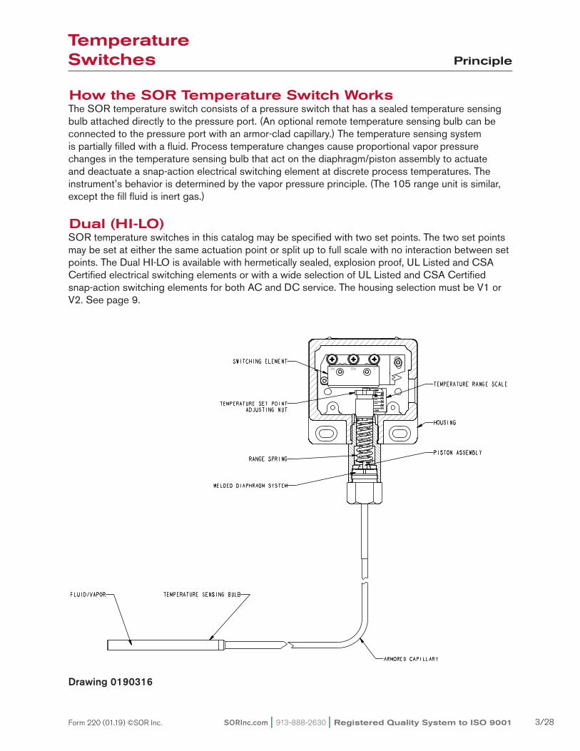
How the SOR Temperature Switch WorksThe SOR temperature switch consists of a pressure switch that has a sealed temperature sensing bulb attached directly to the pressure port. (An optional remote temperature sensing bulb can be connected to the pressure port with an armor-clad capillary.) The temperature sensing system is partially filled with a fluid. Process temperature changes cause proportional vapor pressure changes in the temperature sensing bulb that act on the diaphragm/piston assembly to actuate and deactuate a snap-action electrical switching element at discrete process temperatures. The instrument’s behavior is determined by the vapor pressure principle. (The 105 range unit is similar, except the fill fluid is inert gas.)
Dual (HI-LO)SOR temperature switches in this catalog may be specified with two set points. The two set points may be set at either the same actuation point or split up to full scale with no interaction between set points. The Dual HI-LO is available with hermetically sealed, explosion proof, UL Listed and CSA Certified electrical switching elements or with a wide selection of UL Listed and CSA Certified snap-action switching elements for both AC and DC service. The housing selection must be V1 or V2. See page 9.
Temperature Switches Principle
Drawing 0190316

Registered Quality System to ISO 9001 | 913-888-2630 | SORInc.com4/28 Form 220 (01.19) ©SOR Inc.
Temperature Switches How to Order
Quick Selection GuideBasic SOR temperature switches with standard parts are normally suitable for a variety of industrial applications. Refer to the Quick Selection Guide section on page 5. Corrosive service and particular customer requirements may require optional components. Refer to the How to Order section on this page or the dedicated page to locate optional components, such as: Housings, switching elements, and accessories. Each position in the model number, except ‘Accessories’, must have a designator.
ApplicationsSOR temperature switches in this catalog are suitable for a wide variety of process and fluid power applications. Specific application requirements can normally be met by selecting optional components, such as switching elements. Certain applications may require customized specials. Consult area representative or the factory.
Weatherproof, conventional explosion-proof and hermetically sealed, explosion proof models are presented in this catalog.
How to OrderSteps 1 through 4 are required; steps 5 and 6 are optional. Orders must have complete model numbers, i.e., each component must have a designator.
Step 1: Determine if direct or remote (and capillary length) sensing is required. Select temperature Sensing Bulb Designator from specifications (page 7).
Step 2: Determine the adjustable range required. Select Range Designator from specifications (page 8).
Step 3: Select Housing for type of service (pages 9 and 10).
Step 4: Select Switching Element for housing and electrical service (pages 11 and 12).
Step 5: Select Diaphragm System (page 12).
Step 6: Select Accessories as required for service (pages 13 and 14).
Step 7: Determine if Thermowell is required. Select from tables on page 14 and order as a separate item.
If Agency Listed, Certified or Approved temperature switches are required, see page 15 for components that must be specified.
Model Number System
201 AH-EF 125-U9 -C7A-TTTemperature
Bulb TypeHousing Switching
ElementAdjustable
RangeDiaphragm
SystemPressure Port Accessories

SORInc.com | 913-888-2630 | Registered Quality System to ISO 9001 5/28Form 220 (01.19) ©SOR Inc.
Direct Mount Temperature Switches SPDT Form “C” ContactsMaximum Process Pressure 2300 psi
Adjustable Range
Overrange Temperature
Electrical Rating
@250VAC
Typical Dead Band Model Number
150 to 375oF66 to 190oC
520oF270oC
15 amps 2.2oF 1.2oC201NN-K115-U9-C7A
201L-K115-U9-C7A
5 amps 6.6oF 3.7oC 201AH-EF115-U9-C7A
40 to 225oF5 to 107oC
360oF182oC
15 amps 1.2oF 0.7oC201NN-K125-U9-C7A
201L-K125-U9-C7A
5 amps 3.6oF 2.0oC 201AH-EF125-U9-C7A
-50 to 70oF-45 to 21oC
190oF88oC
15 amps 1.4oF 0.8oC201NN-K135-U9-C7A
201L-K135-U9-C7A
5 amps 4.2oF 2.3oC 201AH-EF135-U9-C7A
Remote Mount Temperature Switches with 6’ Capillary(not shown)SPDT Form “C” ContactsMaximum Process Pressure 2300 psi
Adjustable Range
Overrange Temperature
Electrical Rating
@250VAC
Typical Dead Band Model Number
150 to 375oF66 to 190oC
520oF270oC
15 amps2.2oF 1.2oC
203NN-K115-U9-C7A
203L-K115-U9-C7A
3.3oF 1.8oC 203BA-KB115-U9-C7A
40 to 225oF5 to 107oC
360oF182oC
15 amps1.2oF 0.7oC
203NN-K125-U9-C7A
203L-K125-U9-C7A
1.8oF 1.0oC 203BA-KB125-U9-C7A
-50 to 70oF-45 to 21oC
190oF88oC
15 amps1.4oF 0.8oC
203NN-K135-U9-C7A
203L-K135-U9-C7A
2.1oF 1.2oC 203BA-KB135-U9-C7A
Temperature Switches Quick Selection Guide
Weatherproof-NEMA 4, 4X, IP66(Direct Mount Shown)
Explosion Proof-Conventional(Direct Mount Shown)
Explosion Proof-Hermetically Sealed(Direct Mount Shown)
Wea
ther
proo
f, N
EM
A 4
, 4X
, IP
66
Exp
losi
on P
roof
Cla
ss I,
Gro
ups
C &
D;
Cla
ss II
, Gro
ups
E, F
& G
; Div
isio
ns 1
& 2
Con
tain
s H
erm
etic
ally
Sea
led
Exp
losi
on-P
roof
Sw
itchi
ng E
lem
ent
Cla
ss I,
Gro
ups
A, B
, C &
D; C
lass
II,
Gro
ups
E, F
& G
; Div
isio
ns 1
& 2
Design and specifications are subject to change without notice. For latest revision, see sorinc.com.

Registered Quality System to ISO 9001 | 913-888-2630 | SORInc.com6/28 Form 220 (01.19) ©SOR Inc.
Glossary of Terms
Temperature SwitchA bi-stable electromechanical device that actuates/ deactuates one or more electrical switching element(s) at a predetermined discrete temperature (set point) upon rising or falling temperature.
Adjustable RangeThe span of temperature between upper and lower limits within which the temperature switch can be adjusted to actuate/deactuate. It is expressed for increasing temperature.
Set PointThat discrete temperature at which the temperature switch is adjusted to actuate/deactuate on rising or falling temperature. It must fall within the adjustable range and be called out as increasing or decreasing temperature.
Dead BandThe difference in temperature between the increas-ing set point and decreasing set point. It is expressed as “typical,” which is an average with the increasing set point at mid-adjustable range with the standard K switch element. It is normally fixed (not adjustable).
Hermetically SealedA welded steel capsule with glass-to-metal, factory-sealed electrical leads that isolates the electrical switching element(s) from the environment.
OverrangeOverrange temperature is that temperature to which the sensing bulb can be continuously exposed without causing permanent change of set point or distortion sufficient to cause leakage or significant degradation of the fill fluid. Temperatures greater than overrange could cause permanent damage and render the device inoperative.
Maximum Process PressureThe maximum process pressure to which the temperature sensing bulb should be exposed without being protected by a thermowell.
RepeatabilityThe ability of a temperature switch to successively operate at a set point that is approached from a starting point in the same direction and returns to the starting point over consecutive cycles to establish a temperature profile. The closeness of the measured set point values is normally expressed as percentage of full scale (maximum adjustable range temperature.)
Repeatability is 1% of full scale for ranges 135, 125 and 115. Range 105 has a repeatability of 2% of full scale.
SPDT Switching ElementSingle-Pole, Double-Throw (SPDT) has three connections: C-Common, NO-Normally Open and NC-Normally Closed, which allows the switch to be electrically connected to the circuit in either NO or NC state.
DPDT Switching ElementDPDT is two synchronized SPDT switching elements which actuate together at increasing set point and deactuate together at decreasing set point. Discrete SPDT switching elements allow two independent circuits to be switched; i.e., one AC and one DC.
The synchronization linkage is factory set, and is not field adjustable. Synchronization is verified by connecting test lamps to the switching elements and observing them go “On” simultaneously at actuation and “Off” simultaneously at deactuation.
SOR recognizes that there is not an industry convention with respect to terminology and definitions pertinent to temperature switches. The following list applies to SOR Temperature Switches.
Temperature Switches
SORInc.com | 913-888-2630 | Registered Quality System to ISO 9001 7/28Form 220 (01.19) ©SOR Inc.
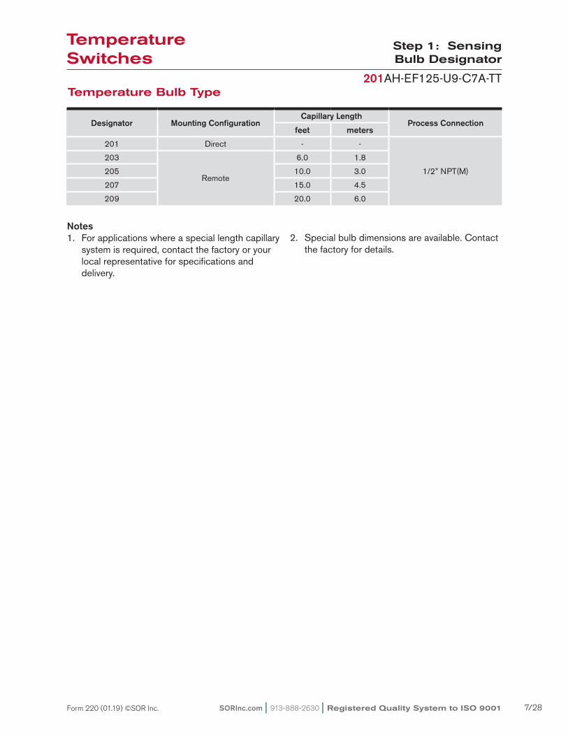
Step 1: Sensing Bulb Designator
201AH-EF125-U9-C7A-TTTemperature Bulb Type
Notes1. For applications where a special length capillary system is required, contact the factory or your local representative for specifications and delivery.
2. Special bulb dimensions are available. Contact the factory for details.
Designator Mounting ConfigurationCapillary Length
Process Connectionfeet meters
201 Direct - -
1/2” NPT(M)
203
Remote
6.0 1.8
205 10.0 3.0
207 15.0 4.5
209 20.0 6.0
Temperature Switches

Registered Quality System to ISO 9001 | 913-888-2630 | SORInc.com8/28 Form 220 (01.19) ©SOR Inc.
* Overrange temperature decreases to 250oF (120oC) when NB option is specified. See accessories on page 13.** Remote mount only. 1 Overrange is reduced to 1150 psi when the CV accessory is selected.
201AH-EF125-U9-C7A-TT
Adjustable Ranges
1. Dead band values are expressed as typical expected at mid-range using the standard K switching element. When optional switching elements are specified, corresponding dead band multipliers must be applied to the
typical dead band values shown in the table whenever optional switching elements other than K, KA or W are used.
2. Dead bands are fixed, except when T or H switching elements are used.
3. Dead band can be widened by selecting an optional switching element with a multiplier greater than 1.0.
Example: Model 201NN-G125-U9-C7A Typical standard dead band: 1.2°F Switching Element G multiplier: 3 Corrected typical dead band: 1.2°(3) = 3.6°F
Step 2: Adjustable Range
Dead Band Considerations
Switching Element Designators Multiplier
K, KA, W 1.0
D, E, J, JR, KB, M, Y 1.5
A, AD, B, EF, G 3.0
L, JF, YY 3.5
AF, EE 4.0
BD, EB, JJ, S 5.0
EG 5.5
AA, BB, GG, JB, JG KK 6.0
LL 6.5
AG 8.5
T 2.5 to 6.5
H 1.0 to 3.0
DesignatorAdjustable Range
Increasing Temperature Typical Dead Band Overrange Temperature
Maximum Process Pressure
°F °C °F °C °F °C psi bar
135 -50 to 70 -45 to 21 1.4 0.8 190 88 23001 158
125 40 to 225 5 to 107 1.2 0.7 360* 182* 23001 158
115 150 to 375 66 to 190 2.2 1.2 520 270 23001 158
105** 300 to 1000 150 to 540 15 8.3 1100 590 1000 70
Temperature Switches

SORInc.com | 913-888-2630 | Registered Quality System to ISO 9001 9/28Form 220 (01.19) ©SOR Inc.
Step 3: Housing
201AH-EF125-U9-C7A-TT
General Purpose NEMA 1
Weatherproof - NEMA 4, 4X, IP66
PP
Electrical: 3/4” NPT(F) - RightMaterial: AluminumSee Agency Listings page 15See Switching Element Groups 1, 2, 3 & 4 on page 10.
Electrical: 3/4” NPT(F) - TopStandard terminal blockMaterial: AluminumSee Agency Listings page 15See Switching Element Groups 1, 3 & 4 on page 10.*V1
Electrical: 3/4” NPT(F) - RightMaterial: AluminumSee Agency Listings page 15See Switching Element Groups 1, 2, 3 & 4 on page 10.NN
Electrical: 3/4” NPT(F) - RightMaterial: Carbon Steel
See Switching Element Groups 1 & 3 on page 10.
N6
Contains UL Listed and CSA Certified hermetically sealed switching element.Electrical: 1/2” NPT(M) - TopMaterial: Copper-free** aluminumSee Switching Element Group 5 on page 10.AG
Contains UL Listed and CSA Certified hermetically sealed switching element.Electrical: 1/2” NPT(M) - TopMaterial: 316SSSee Switching Element Group 5 on page 10.AH
Electrical: 3/4” NPT(F) - Left, RightMaterial: AluminumSee Switching Element Groups 1, 2, 3 & 4 on page 10.P3
Electrical: Exposed contactsMaterial: AluminumOpen bracket with exposed switching element - does not meet NEMA 1See Switching Element Groups 1 & 3 on page 10.
H3
Electrical: 3/4” NPT(F) - Left, RightMaterial: AluminumSee Agency Listings page 15See Switching Element Groups 1, 2, 3 & 4 on page 10.
N3
Electrical- RN: 3/4” NPT(F) - RightElectrical- RM: M20 x 1.5- RightStandard terminal blockMaterial: AluminumSee Agency Listings page 15See Switching Element Groups 1, 2, 3 & 5 on page 10.
Electrical: 90o conduit block 1/2” NPT(M)18” free wire leadsMaterial: Series 2000 AluminumSwitching Element AD only.AC
BH
Electrical: 3/4” NPT(F) - RightMaterial: AluminumCover: Heavy Duty with Viton gasketSee Switching Element Groups 1, 2, 3 & 4 on page 10.N4
Electrical- RT: 3/4” NPT(F) - RightElectrical- RS: M20 x 1.5 - RightStandard terminal blockMaterial: 316SSSee Agency Listings page 15See Switching Element Groups 1, 2, 3 & 5 on page 10.
Electrical: 3/4” NPT(F) - RightManual reset onlyStandard terminal blockMaterial: AluminumSee Agency Listings page 15See Switching Element Group 7 on page 10.
Contains UL Listed and CSA Certified hermetically sealed switching elements.Electrical: 3/4” NPT(F) - TopMaterial: AluminumSee Switching Element Group 5 on page 10.
Contains UL Listed and CSA Certified hermetically sealed switching elements.Electrical: 3/4” NPT(F) - TopMaterial: Copper-free** aluminumWeatherproof: NEMA 4/4XSee Switching Element Group 6 on page 10.*BA
RNRM
RT RS
BG
RB
*V2
Hazardous Locations - Hermetically Sealed Switching Element NEMA 4, 4X, 7, 9, IP66
* Not recommended for direct mount where vibration is expected. Housing should be securely mounted to a flat surface (bulkhead or panel rack) or pipe stanchion.** Consult the factory.
ATEX/IECEx Certified(Ex db IIC T6/T5 Gb)Electrical: 1/2” NPT(M) - TopMaterial: Copper-free** aluminumSee Agency Listings page 15See Switching Element Group 5 on page 10.
ATEX/IECEx Certified(Ex db IIC T6/T5 Gb)Electrical: 1/2” NPT(M) - TopMaterial: 316SSSee Agency Listings page 15See Switching Element Group 5 on page 10.
Temperature Switches

Registered Quality System to ISO 9001 | 913-888-2630 | SORInc.com10/28 Form 220 (01.19) ©SOR Inc.
* Not recommended for direct mount where vibration is expected. Housing should be securely mounted to a flat surface (bulkhead or panel rack) or pipe stanchion.** Consult the factory.
UL Listed Class I, Groups C & D; Class II, Groups E, F & G; Divisions 1 & 2 as an outlet box onlyElectrical: 3/4” NPT(F) - RightMaterial: Cast IronWeatherproof with Option CGSee Switching Element Groups 1 & 3 below.
*L
Hazardous Locations - Conventional Explosion Proof NEMA 4, 4X, 7, 9, IP66
UL Listed Class I, Groups C & D; Class II, Groups E, F, & G; Divisions 1 & 2 as an outlet box onlyElectrical: 3/4” NPT(F) - Left, Right, TopMaterial: Cast IronWeatherproof with Option CGSee Switching Element Groups 1, 3, & 7 below.
*S
Class 1, Groups A, B, C, D; Class II, Groups E, F, & G, Divisions 1 & 2 as an outlet box only Electrical 3/4” NPT(F) - Left, Right, TopMaterial (Housing): AluminumMaterial (Cover): AluminumLine Mounted. Weatherproof with Option CG.See Switching Element Groups 1 & 3 below.
*TA
UL Listed Class I, Groups C & D; Class II, Groups E, F & G; Divisions 1 & 2 as an outlet box onlyElectrical: 3/4” NPT(F) - RightMaterial: Copper-free**aluminumWeatherproofSee Switching Element Groups 1, 2, 3 & 4 below.
*LC
UL Listed Class I, Groups C & D; Class II, Groups E, F & G; Divisions 1 & 2 as an outlet box onlyElectrical: 3/4” NPT(F) - Left, Right, TopMaterial: Copper-free**aluminumWeatherproofSee Switching Element Groups 1, 2, 3, 4 & 7 below.
*SC
Separate electrical and set point adjustment compartments WeatherproofStandard terminal blockSee agency listings on page 15.
*B3
*B4
*B5
*B6
Electrical: 3/4” NPT(F) - Left, RightMaterial: Aluminum
Electrical: M20 x 1.5 - Left, RightMaterial: Aluminum
Electrical: M20 x 1.5 - Left, RightMaterial: Cast Iron
Electrical: 3/4” NPT(F) - Left, RightMaterial: Cast Iron
Switching Element Groups 1, 2, 3, 4 & 5 below.
*BD only available with RN & RT housings **C micro switch is not available in L, S and TA housings
Switching Element Group / Housing Compatibility
Step 3: Housing
201AH-EF125-U9-C7A-TT
Group 1 Group 2 Group 3 Group 4 Group 5 Group 6 Group 7
A, AA, B, BB, BD*, C**, E, EE, G, J, JJ, K, KA, L, S, W, Y
GG, KK, LL, YY
T HAF, AG, EF, EG,
JF, JGEB, JB, JR,
KBD, M
Temperature Switches

SORInc.com | 913-888-2630 | Registered Quality System to ISO 9001 11/28Form 220 (01.19) ©SOR Inc.
Switching Element Service
Electrical Contact
Type
Electrical Connection
Type
AC Rating DC Rating Resistive Dead Band Multiplier Designator
Volts Amps Volts Amps Volts Amps SPDT DPDT SPDT DPDT
Normal Service AC
250 15 125 0.4* 30 5.0* 1.0 6.0 K KK
Low PowerGold Contacts
125 1 - - 28 1.0* 1.0 - KA N/A
125 1 - - 30 1.0 1.5 5.0 J JJ
Wide Dead Band AC 250 15 125 0.5 - - 3.0 6.0 G GG
AC or DC 250 11 125 0.5* 30 5.0 3.0 6.0 A AA
Wide Dead Band DC 250 15 125 0.5 30 10.0* 3.5 6.5 L LL
Narrow Dead Band DC
250 5 125 0.5* 30 5.0* 1.5 4.0 E EE
Hi-Ambient Temperature Rating - 400°F
250 5 125 0.3 - - 3.0 6.0 B BB
250 5 125 0.5* - - 1.5 3.5 Y YY
250 5 125 0.3 - - 1.0 - W N/A
Potted Wire Leads 1/2” NPT(M) Condition Connection
250 11 125 0.5* 30 5.0 3.0 - AD N/A
Wide Adjustable Dead Band
250 15 125 0.4* - -2.5 to
6.5- T N/A
Narrow Adjustable Dead Band
250 15 - - - - 1 to 3 - H N/A
Manual Reset - Decreasing Temperature (Automatic Actuation-Increasing Temperature)
250 15 125 0.5 - - 1.5 -
D N/A
Manual Reset - Increasing Temperature (Automatic Actuation-Decreasing Temperature)
M N/A
Corrosion Resistant Explosion- Proof Hermetically Sealed Switching Element
250 15 125 0.4* 30 5.0* 1.5 - KB N/A
250 5 125 0.5* 30 5.0* - 5.0 N/A EB
250 11 125 0.5* 30 5.0 4.0 8.5 AF AG
250 5 125 0.5* 30 5.0 3.0 5.5 EF EG
Corrosion Resistant, Explosion Proof, Lower-Power Service Hermetically Sealed Gold Contacts
125 1 - - 28 1.0* 1.5 - JR N/A
125 1 - - 30 1.0 - 6.0 N/A JB
125 1 - - 30 1.0 3.5 6.0 JF JG
Explosion-Proof EEx d IIC T6
250 7 250 0.25 30 7.0 5.0 - BD N/A
Step 4: Switching Element
201AH-EF125-U9-C7A-TT
Cross reference compatibility chart on page 10 to ensure that switching element will fit in housing.
Sin
gle
Sw
itchi
ng E
lem
ent S
PD
T - (
1) S
PD
TD
oubl
e S
witc
hing
Ele
men
t DP
DT
-(2)
SP
DT
Syn
chro
nize
d ac
tuat
ion/
deac
tuat
ion
at in
crea
sing
/dec
reas
ing
Set
Poi
nts
K, K
A, G
, L, C
, N, S
, Y, W
Sw
itchi
ng E
lem
ents
- S
crew
Ter
min
als.
All
othe
r Sw
itchi
ng E
lem
ents
- 18
” 18
AW
G C
olor
-Cod
ed W
ire L
eads
exc
ept w
hen
term
inal
blo
cks
are
spec
ified
. T
& H
Sw
itchi
ng E
lem
ents
- C
onsu
lt th
e fa
ctor
y.
Temperature Switches

Registered Quality System to ISO 9001 | 913-888-2630 | SORInc.com12/28 Form 220 (01.19) ©SOR Inc.
Notes1. Double switching elements have wire leads
except when supplied in housings RN, RT, RB, B3, B4, B5, B6 and V1. Terminal blocks are standard in these housings.
2. Dead band multipliers must be applied to the typical dead band figures given in the specification tables on page 8.
3. Switching element ambient temperature limits: -65 to 400oF (-54 to 200oC) B, Y, W -65 to 250oF (-54 to 120oC) A, E & J -40 to 167oF (-40 to 75oC) AF, AG, EB, EF, EG, JB, JF,
JG, JR, KB -13 to 158oF (-25 to 70oC) BD -65 to 180oF (-54 to 80oC) All others
4. The hermetically sealed switching element capsule is UL Listed, CSA Certified and TestSafe Approved as an explosion proof snap switch according to the table with conditions and exceptions specified in Note 3.
5. Switching Elements W & Y have Elgiloy springs. 6. Certain switching elements can handle
greater voltage and/or amperage. Consult the factory should your requirements exceed catalog values. All switching elements above except BD are UL Listed and CSA Certified. The DC current ratings marked with an asterisk (*) are not UL Listed but have been verified by testing and/or experience.
7. Cross reference compatibility chart at the bottom of page 10 to ensure that switching element will fit in housing.
Step 4: Switching Element
201AH-EF125-U9-C7A-TT
Agency Hazardous Location Conditions Designator
UL ListedCSA
Certified
Class I, Groups A, B C & D; Class II, Groups E, F & G; Divisions 1 & 2
AF, EF, AG, EG, KB, EB, JB, JF,
JG, JR
TestSafe Approved
Ex s Zone 1 IIC T4 IP65Ex tD A21 T105°C IP65
AF, EF, AG, EG, KB, EB
Temperature Switches
Step 5: Diaphragm System
201AH-EF125-U9-C7A-TT
Diaphragm
Pressure Port
U9
U9 Welded Diaphragm SystemA metal diaphragm is welded to the pressure port, thereby, eliminating the o-ring.

SORInc.com | 913-888-2630 | Registered Quality System to ISO 9001 13/28Form 220 (01.19) ©SOR Inc.
Step 6: Accessories
201AH-EF125-U9-C7A-TT
Accessory/Option & Description Designator Neoprene cover gasket (o-ring) to make L, S and TA explosion-proof housings weathertight. CGATEX/IECEx approved temperature switch. See Agency Listings on page 15 for details. CLCSA Certified temperature switch. Available with PP, NN, RB, RN, RT, B3, B6 & V1. Housing has earth (ground) lug.See Agency Listings on page 15 for details. CS
Canadian Registration Number (CRN) - Process ratings may be affected. Consult the factory for details. CVCemented cover gasket on weathertight housings. GCSealed electrical lead adapter. Provides protection to housing interior, switching element and dry side of pressure sensing assembly from condensate in electrical conduit and corrosive atmospheres. (Protrudes approximate 2” from housing.) GG
Universal terminal box. Stainless steel. 1/2” NPT(F). ATEX/IECEx Certified Ex db IIC T4, T5 & T6 Gb. HBUniversal terminal box. Stainless steel. M20 x 1.5(F). ATEX/IECEx Certified Ex db IIC T4, T5 & T6 Gb. HBMEUniversal terminal box. Stainless steel. 1/2” NPT(F). FM Approved and CSA Certified Explosion-proof Class I, Groups A, B, C, & D; Class II, Groups E, F, & G, Class III; Divisions 1 & 2 (NEMA 4X IP65) HT
Breather DrainCrouse Hinds ECD-15 for Hazardous Locations Class I, Groups C & D; Class II, Groups E, F & G; on S or SC housings only. KKSintered metal plug in weathertight housing.
Terminal block. 6-place compression type standard in B and R series housings. Optional in LC and SC housings. Not available with all housings. Consult the factory. LL
Multi-Listed temperature switch. ATEX/IECEx, CSA & UL. Available with B3 & B6 housings. See Agency Listings on page 15 for details. ML
Special construction to minimize the effect of across ambient temperature changes. Available on Ranges 135 and 125 only. Reduces overranges to 250°F (120°C) on Range 125. NB
Compliance to NACE Certification MR-01 1-75. NCINMETRO approved temperature switch. See Agency Listings on page 15 for details. NMPipe (stanchion) mounting kit for (1-1/2 to 2” pipe). Order as a separate line item for UL Listed and CSA Certified temperature switches. PK
Tag, fiber. Attached with plastic wire to housing. Stamped with customer-specified tagging information. PPPowder coat epoxy coating. No coating on stainless steel parts or plated screws. (500 hours-salt spray) PYTag, stainless steel. Attached with stainless steel wire to housing. Stamped with customer-specified tagging information. (2 lines, 18 characters and spaces per line.) RR
Explosion-proof and weathertight electrical junction box with screw terminals. Aluminum 3/4” NPT(F) top or right conduit connections as required. UL Listed and CSA Certified Class I, Groups A, B, C & D; Class II, Groups E, F & G; Divisions 1 & 2, (AG, AH, BA, L, LC, S, SC & TA housings). Includes cover o-ring for weathertight applications.
TB
Factory set and potted to prevent future adjustment. This option results in permanent Set point. Available only on housing AC, AG, AH, BG and BH. TP
Taiwan Safety Mark. Requires IECEx approval, See Agency Listings on page 15 for details. TSOversize stainless steel nameplate or separate stainless steel tag. Permanently attached to housing. Stamped with customer-specified tagging information. TT
Fungicidal varnish. Covers exterior and interior except working parts. VVUL Listed temperature switch available with B3 or B6 housing. See Agency Listings on page 15 for details. WV“X” is used as a suffix to the model number for special requirements. Each “X” must by completely identified in the text of the order or inquiry. When more than one “X” is required, use “X” followed by the number of such items. For example, “X3” means three separate otherwise unidentifiable requirements.
X
Epoxy coating. Exterior only. Polyamide epoxy with 316SS pigment. (200 hours-salt spray) YYChained cover with captive screws to conform to former JIC specification. ZZ
Temperature Switches

Registered Quality System to ISO 9001 | 913-888-2630 | SORInc.com14/28 Form 220 (01.19) ©SOR Inc.
1. Determine insertion length from specification table.2. Specify thermowell for either direct or remote mounted temperature switches from specifications
tables.3. Specify process connection threading from specification table below.4. The thermowell must be ordered as a separate item. Thermowells are 316SS (347SS on
275TW-NF100). Consult the SOR representative in your area or the factory for special material.5. Special sensing bulb diameter and lengths are available. Consult the SOR representative in your
area or the factory to discuss your requirements.
Specifications and Dimensions
*Model 275TW-NF100 must be used with Range 105.
Thermowell Model Number
Available Sensing Bulb(s)
Mounting
U Insertion Length
A Element Length
B Bore
Diameter
Q Insertion Diameter
Process Connection in NPT(M)
Maximum Process Pressure201
203
205
207
209 mm in. mm in. mm in. mm in.
245 TW-DM 075 uDirect 114.3 4.5 152.6 6 10.4 0.41 19.1 0.75
3/4
6200 psi @ 500°F
245 TW-DM 100 u 1
245 TW-RM 075 u uRemote 114.3 4.5 152.6 6 10.4 0.41 19.1 0.75
3/4
245 TW-RM 100 u u 1
275 TW-RM 075 u u u uRemote 190.5 7.5 228.6 9 9.9 0.39 19.1 0.75
3/4
275 TW-RM 100 u u u u 1
*275 TW-NF 100 u u u u Remote 190.5 7.5 228.6 9 16.8 0.66 26.9 1.06 14700 psi
@ 1000°F
Test CertificatesCertificates C1 C3 C4 C5 C6 C8 B5 B6 B7 A1
Calibration ¿ ¿ ¿ ¿ ¿
Inspection Report ¿ ¿ ¿ ¿
Compliance / Conformance ¿ ¿ ¿
Dielectric Test ¿ ¿
Insulation Resistance ¿ ¿ ¿
Typical Material of Wetted Parts ¿ ¿
Step 7: Thermowell
Step 6: Accessories
ISO-9001
14685 W 105TH ST LENEXA, KS 66215 USA913-888-2630SORINC.COM
MODELNUMBER
PARTNUMBER MATERIAL
UINSERTION
LENGTH
AELEMENTLENGTH
BBORE
DIAMETER
QINSERTIONDIAMETER
PROCESSCONNECTION
MAXIMUMPROCESSPRESSURE
245 TW-DM 075 0029070316SST 114.3
4.50152.66.00
10.40.41
19.10.75
3/4 NPTM
6200 PSI @ 500°F
245 TW-DM 100 0029072 1 NPTM245 TW-RM 075 0029070
316SST 114.34.50
152.66.00
10.40.41
19.10.75
3/4 NPTM245 TW-RM 100 0029072 1 NPTM275 TW-RM 075 0029071
316SST 190.57.50
228.69.00
9.90.39
19.10.75
3/4 NPTM275 TW-RM 100 0029073 1 NPTM
275 TW-NF 100 0029074 347SST 190.57.50
228.69.00
16.80.66
26.91.06 1 NPTM 4700 PSI @ 1000°F
Model Name: 0190020.PART/7/1
PRODUCT CERTIFICATION DRAWINGALL DIMENSIONS ARE ±1/16 INUNLESS OTHERWISE SPECIFIED
MMLINEAR = IN
DRAWN BY
K MITCHELLCHECKED BY
M SMITHENGINEER APPROVAL
J MODIGDATE
14 FEB 2011THIS DRAWING IS THE EXCLUSIVE PROPERTY OF SOR.
NO USE WHATSOEVER OF THE INFORMATION CONTAINEDHEREON, NOR REPRODUCTION IN WHOLE OR PART MAY BE
MADE WITHOUT THE EXPRESS WRITTEN PERMISSION OF SOR.
TITLE
DIM DWGTHERMOWELL
EO NUMBER: 4991
SCALE: 1.50
DO NOT SCALE PRINT
DRAWING NUMBER REV
0190020 7
SHEET 1 OF 1DWG SIZE
B
MODEL # SALES ORDER # LINE ITEM # PURCHASE ORDER #
PROCESS CONNECTION
1/2 NPTF
1SCALE
44.51.75
6.40.25
Q
A ELEMENT LENGTH
U INSERTION LENGTH
B BORE25.41.00
Reset Form
Drawing 0190020
Temperature Switches

SORInc.com | 913-888-2630 | Registered Quality System to ISO 9001 15/28Form 220 (01.19) ©SOR Inc.
Agency Listings
CSA
ATEX/IECEx or INMETRO
UL
For Hazardous Locations - Class 1, Groups B, C & D; Class II, Groups E, F & G
Bulb Housing Switching Element Range Diaphragm Pressure Port
Material & Conn. Size
Accessories
ALL B3, B6
A, AA, AF, AG, B, BB, C, E, EE, EF, EG, G, GG, H, J, JF, JG, JJ, K, KA, KK, L, LL, P, S,
T, W, Y, YY
ALL ALL ALL
CS or ML Required.
All except CG, GC, GG, HB, HT, KK, LL, ME, TB, TP, TS, ZZ
General Purpose and Weatherproof (CSA Type 4)
ALL
FP (General Purpose
A, AA, B, BB, C, E, EE, G, GG, H, J, JJ, JL, K, KK, KA, L,
LL, S, T, W, Y, YY
ALL U9C7A
Standard Others as Required
CS Required. All except
GC, LL, TS
NN (Type 4)
RN (Type 4) RT (Type 4)
A, AA, AF, AGT, B, BB, C, E, EE, EF, EG, G, GG, GA, H, J, FJ, JG, JJ, JL, K, KK, KA, L, LL,
S, T, W, Y, YY
RB (type 4) RH (Type 4)
D, DA, M (Manual reset only)
V1 (Type 4)A, AA, B, BB, C, E, EE, G,
GA, H, J, JJ, K, KA, L, LA, S, SA, T, W, Y
Ex db IIC T6/T5 Gb
Bulb Housing Switching Element Range Diaphragm Pressure Port
Material & Conn. Size
Accessories
ALLB3, B4, B5,
B6
A, AA, AF, AG, B, BB, C, E, EE, EF, EG, G, GG, H, J, JF, JG, JJ, JL, K, KA, KK, L, LL, P, N, S, T, W, Y, YY
ALL ALL ALL
CL (for all Hsgs)or ML (for B3/B6 Hsgs)
Req’d for ATEX/IECEx
NM Required for INMETRO
All except CG, GC, GG, HB, HT, KK, LL,
ME, TB, TP, ZZ
ALL BG, BH AF, AG, EF, EG, JF, JG ALL ALL ALL
BB, HB, HBME, PP, RR, TP, TS, TT, VV, YY
NM Required for INMETRO
Ex ia IIC T6...T4 Gb
ALLRN, RM, RT,
RSJ, JJ, JF, JG ALL ALL ALL
NC, PK, TS, X
CL Required for ATEX/IECEx
NM Required for INMETRO
For Hazardous Locations - Class I, Groups B, C, & D; Class II, Groups E, F, & G
Bulb Housing Switching Element Range Diaphragm Pressure Port
Material & Conn. Size
Accessories
ALL B3, B6
A, AA, AF, AG, B, BB, C, E, EE, EF, EG, G, GG, H,
J, JF, JG, JJ, K, KA, KK, L, LL, P, S, T, W, Y, YY
ALL ALL ALL
WV or ML Required.
All except CG, GC, GG, HB, HT, KK, LL, ME, TB, TP, TS, ZZ
Permit for instruments used and operated in hazardous industrial facilities in Russia. Standard on most models. Certificate available on request.
Temperature Switches
Rostechnadzor (RTN) Certificate
Registered Quality System to ISO 9001 | 913-888-2630 | SORInc.com16/28 Form 220 (01.19) ©SOR Inc.
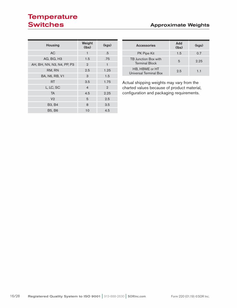
Actual shipping weights may vary from the charted values because of product material, configuration and packaging requirements.
Approximate Weights
Housing Weight (lbs) (kgs)
AC 1 .5
AG, BG, H3 1.5 .75
AH, BH, NN, N3, N4, PP, P3 2 1
RM, RN 2.5 1.25
BA, N6, RB, V1 3 1.5
RT 3.5 1.75
L, LC, SC 4 2
TA 4.5 2.25
V2 5 2.5
B3, B4 8 3.5
B5, B6 10 4.5
Accessories Add(lbs) (kgs)
PK Pipe Kit 1.5 0.7
TB Junction Box with Terminal Block
5 2.25
HB, HBME or HT Universal Terminal Box
2.5 1.1
Temperature Switches
SORInc.com | 913-888-2630 | Registered Quality System to ISO 9001 17/28Form 220 (01.19) ©SOR Inc.
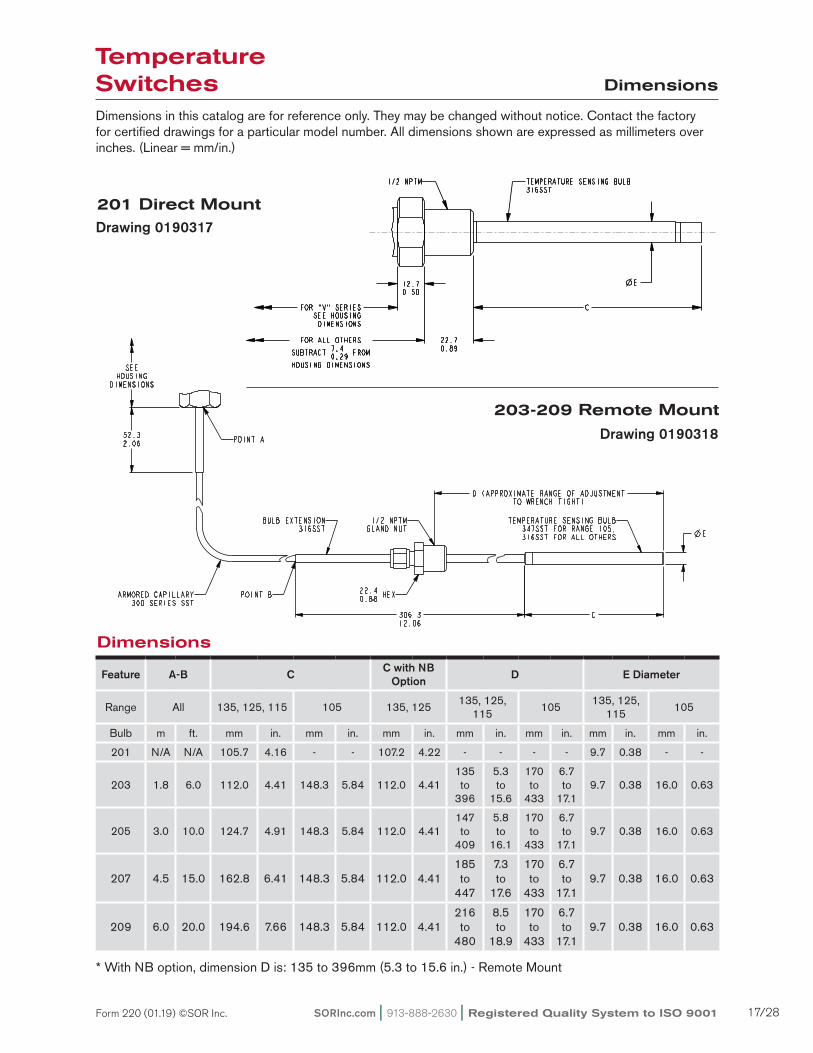
Dimensions
Dimensions
Dimensions in this catalog are for reference only. They may be changed without notice. Contact the factory for certified drawings for a particular model number. All dimensions shown are expressed as millimeters over inches. (Linear = mm/in.)
201 Direct Mount
* With NB option, dimension D is: 135 to 396mm (5.3 to 15.6 in.) - Remote Mount
Feature A-B C C with NB Option D E Diameter
Range All 135, 125, 115 105 135, 125135, 125,
115105
135, 125, 115
105
Bulb m ft. mm in. mm in. mm in. mm in. mm in. mm in. mm in.
201 N/A N/A 105.7 4.16 - - 107.2 4.22 - - - - 9.7 0.38 - -
203 1.8 6.0 112.0 4.41 148.3 5.84 112.0 4.41135 to
396
5.3 to
15.6
170 to
433
6.7 to
17.19.7 0.38 16.0 0.63
205 3.0 10.0 124.7 4.91 148.3 5.84 112.0 4.41147 to
409
5.8 to
16.1
170 to
433
6.7 to
17.19.7 0.38 16.0 0.63
207 4.5 15.0 162.8 6.41 148.3 5.84 112.0 4.41185 to
447
7.3 to
17.6
170 to
433
6.7 to
17.19.7 0.38 16.0 0.63
209 6.0 20.0 194.6 7.66 148.3 5.84 112.0 4.41216 to
480
8.5 to
18.9
170 to
433
6.7 to
17.19.7 0.38 16.0 0.63
203-209 Remote Mount
Drawing 0190317
Drawing 0190318
Temperature Switches

Registered Quality System to ISO 9001 | 913-888-2630 | SORInc.com18/28 Form 220 (01.19) ©SOR Inc.
Dimensions
Dimensions in this catalog are for reference only. They may be changed without notice. Contact the factory for certified drawings for a particular model number. Dimensions in this catalog are expressed as millimeter over inches (Linear = mm/in.).
Weatherproof-Non-Hazardous Service (NEMA 4, 4X, IP66)
Housing: NN, N3, N4, PP, P3
Housing: N6
Drawing 0190157
Drawing 0190173
ISO-9001
14685 W 105TH ST LENEXA, KS 66215 USA913-888-2630SORINC.COM
33.31.31
69.92.75
108.14.25
66.92.64
159.16.26
52.32.06
306.312.06
C E
D (TO WRENCH TIGHT)
56.52.22
28.61.13
26.11.03
40.51.59
7.10.28
Model Name: 0190157.ASSEM/4/0
PRODUCT CERTIFICATION DRAWINGALL DIMENSIONS ARE ±1/16 INUNLESS OTHERWISE SPECIFIED
MMLINEAR = IN
DRAWN BY
K MITCHELLCHECKED BY
M SMITHENGINEER APPROVAL
J MODIGDATE
23 NOV 2010THIS DRAWING IS THE EXCLUSIVE PROPERTY OF SOR.
NO USE WHATSOEVER OF THE INFORMATION CONTAINEDHEREON, NOR REPRODUCTION IN WHOLE OR PART MAY BE
MADE WITHOUT THE EXPRESS WRITTEN PERMISSION OF SOR.
TITLE
DIMENSION DRAWING 203/205/207/209NN/N3/N4/PP/P3
EO NUMBER: 4991
SCALE: 0.56
DO NOT SCALE PRINT
DRAWING NUMBER REV
0190157 4
SHEET 1 OF 1DWG SIZE
B
MODEL # SALES ORDER # LINE ITEM # PURCHASE ORDER #SALES PAGE
STANDARD MODELS
BULB MODEL #
LENGTHE
A-B C D
203 182972
112.04.41
125.7 381.8 TO 4.95 15.03
9.70.38
205 3048120
124.74.91
138.4 394.5 TO 5.45 15.53
207 4572180
162.86.41
176.5 432.6 TO 6.95 17.03
209 6096240
194.67.66
208.3 464.3 TO 8.20 18.28
W/NB OPTION125, 135
RANGE ONLY
SEE ABOVEPER PROBEMODEL #
112.04.41
125.7 381.8 TO 4.95 15.03
HI-TEMP105 RANGE
SEE ABOVEPER PROBEMODEL #
148.35.84
162.1 418.1 TO 6.38 16.4616.00.63
NON-STANDARD MODEL DIMENSIONS
POINT A
CLEARANCE SLOTS
FOR 6.40.25
HARDWARE WITH63.52.50 MIN TO 76.2
3.00 MAX
MOUNTING CENTERS
ARMOREDCAPILLARY
POINT B
22.40.88 HEX
1/2 NPTMGLAND NUT
BULBEXTENSION
TEMPERATURESENSING BULB
ELECTRICALCONNECTION3/4 NPTF STD1/2 NPTF OPT
(BOTH SIDES ONN3 & P3 HSGS)
NN & N3 = (SHOWN)
N4 = ADD 4.60.18
PP & P3 = SUBTRACT 1.50.06
1
Reset Form
Temperature Switches

SORInc.com | 913-888-2630 | Registered Quality System to ISO 9001 19/28Form 220 (01.19) ©SOR Inc.
Dimensions
Weatherproof-Non-Hazardous Service (NEMA 4, 4X, IP66)
Dimensions in this catalog are for reference only. They may be changed without notice. Contact the factory for certified drawings for a particular model number. Dimensions in this catalog are expressed as millimeter over inches (Linear = mm/in.).
ISO-9001
14685 W 105TH ST LENEXA, KS 66215 USA913-888-2630SORINC.COM
139.95.51
306.312.06
27.81.09
68.62.70
52.42.06
186.27.33
114.34.50
9.50.38
27.01.06
70.02.76
2X
MOUNTINGHOLES
7.10.28
E
C
57.22.25
D (TO WRENCH TIGHT)
STANDARD MODELS
BULB MODEL #
LENGTH BULB
A-B C D E
203 182972
112.04.41
125.7 381.8 TO 4.95 15.03
9.70.38
205 3048120
124.74.91
138.4 394.5 TO 5.45 15.53
207 4572180
162.86.41
176.5 432.6 TO 6.95 17.03
209 6096240
194.67.66
208.3 464.3 TO 8.20 18.28
W/ NB OPTION125, 135
RANGE ONLY
SEE ABOVEPER PROBEMODEL NO.
112.04.41
125.7 381.8 TO 4.95 15.03
HI-TEMP105 RANGE
SEE ABOVEPER PROBEMODEL NO.
148.35.84
162.1 418.1 TO 6.38 16.4616.00.63
NON-STANDARD MODEL DIMENSIONS
Model Name: 0190094.ASSEM/4/0
PRODUCT CERTIFICATION DRAWINGALL DIMENSIONS ARE ±1/16 INUNLESS OTHERWISE SPECIFIED
MMLINEAR = IN
DRAWN BY
K MITCHELLCHECKED BY
M SMITHENGINEER APPROVAL
J MODIGDATE
08 FEB 2011THIS DRAWING IS THE EXCLUSIVE PROPERTY OF SOR.
NO USE WHATSOEVER OF THE INFORMATION CONTAINEDHEREON, NOR REPRODUCTION IN WHOLE OR PART MAY BE
MADE WITHOUT THE EXPRESS WRITTEN PERMISSION OF SOR.
TITLE
DIM DWG 203/209 V1 DUAL HI-LO
EO NUMBER: 4991
SCALE: 0.70
DO NOT SCALE PRINT
DRAWING NUMBER REV
0190094 5
SHEET 1 OF 1DWG SIZE
B
MODEL # SALES ORDER # LINE ITEM # PURCHASE ORDER #
POINT A
ARMOREDCAPILLARY
POINT B
BULBEXTENSION
22.40.88 HEX
1/2 NPTMGLAND NUT
TEMPERATURESENSING BULB
ELECTRICALCONNECTION
3/4 NPTF (STD)1/2 NPTF (OPT)
Reset Form
Housing: RM, RN, RS, RT
Housing: V1 Drawing 0190094
Drawing 0190136
ISO-9001
14685 W 105TH ST LENEXA, KS 66215 USA913-888-2630SORINC.COM
52.32.06
306.312.06
33.31.31
69.92.75
52.02.05
107.34.22
26.21.03
28.61.13
40.51.59
66.92.64
184.17.25
CLEARANCE SLOTS FOR 6.40.25
HARDWARE WITH63.52.50 MIN TO 76.2
3.00 MAX
MOUNTING CENTERS
7.10.28
65.62.58
E
C
ELECTRICALCONNECTION
SEE CHART
D (TO WRENCH TIGHT)
Model Name: 0190136.ASSEM/5/0+
PRODUCT CERTIFICATION DRAWINGALL DIMENSIONS ARE ±1/16 INUNLESS OTHERWISE SPECIFIED
MMLINEAR = IN
DRAWN BY
K MITCHELLCHECKED BY
M SMITHENGINEER APPROVAL
M MODIGDATE
03 JUN 2011THIS DRAWING IS THE EXCLUSIVE PROPERTY OF SOR.
NO USE WHATSOEVER OF THE INFORMATION CONTAINEDHEREON, NOR REPRODUCTION IN WHOLE OR PART MAY BE
MADE WITHOUT THE EXPRESS WRITTEN PERMISSION OF SOR.
TITLE
DIM DWG 203/209 R-SERIES
EO NUMBER: 5090
SCALE: 0.50
DO NOT SCALE PRINT
DRAWING NUMBER REV
0190136 6
SHEET 1 OF 1DWG SIZE
B
MODEL # SALES ORDER # LINE ITEM # PURCHASE ORDER #SALES PAGE
STANDARD MODELS
BULB MODEL #
LENGTHE
A-B C D
203 182972
112.04.41
125.7 381.8 TO 4.95 15.03
9.70.38
205 3048120
124.74.91
138.4 394.5 TO 5.45 15.53
207 4572180
162.86.41
176.5 432.6 TO 6.95 17.03
209 6096240
194.67.66
208.3 464.3 TO 8.20 18.28
W/NB OPTION125, 135
RANGE ONLY
SEE ABOVEPER PROBEMODEL #
112.04.41
125.7 381.8 TO 4.95 15.03
HI-TEMP105 RANGE
SEE ABOVEPER PROBEMODEL #
148.35.84
162.1 418.1 TO 6.38 16.4616.00.63
NON-STANDARD MODEL DIMENSIONS
HOUSING ELECTRICALCONNECTION
RL3/4 NPTF STD1/2 NPTF OPT
LH & RH
RM M20 X 1.5 FRH ONLY
RN3/4 NPTF STD1/2 NPTF OPT
RH ONLY
RS M20 X 1.5 FRH ONLY
RT3/4 NPTF STD1/2 NPTF OPT
RH ONLY
RU3/4 NPTF STD1/2 NPTF OPT
LH & RH
RW M20 X 1.5 FLH & RH
RY M20 X 1.5 FLH & RH
POINT A
ARMOREDCAPILLARY
TEMPERATRUESENSING BULB
1/2 NPTMGLAND NUT
22.40.88 HEX
POINT B
BULBEXTENSION
1
Reset Form
Temperature Switches

Registered Quality System to ISO 9001 | 913-888-2630 | SORInc.com20/28 Form 220 (01.19) ©SOR Inc.
Dimensions
Weatherproof-Non-Hazardous Service (NEMA 4, 4X, IP66)
Dimensions in this catalog are for reference only. They may be changed without notice. Contact the factory for certified drawings for a particular model number. Dimensions in this catalog are expressed as millimeter over inches (Linear = mm/in.).
Housing: RB - Manual Reset Drawing 0190230
Temperature Switches

SORInc.com | 913-888-2630 | Registered Quality System to ISO 9001 21/28Form 220 (01.19) ©SOR Inc.
Dimensions
Conventional Explosion Proof
Dimensions in this catalog are for reference only. They may be changed without notice. Contact the factory for certified drawings for a particular model number. Dimensions in this catalog are expressed as millimeter over inches (Linear = mm/in.).
Housing: L
Housing: B3, B4, B5, B6
Drawing 0190026
Drawing 0190312
Temperature Switches

Registered Quality System to ISO 9001 | 913-888-2630 | SORInc.com22/28 Form 220 (01.19) ©SOR Inc.
Dimensions
Conventional Explosion Proof
Dimensions in this catalog are for reference only. They may be changed without notice. Contact the factory for certified drawings for a particular model number. Dimensions in this catalog are expressed as millimeter over inches (Linear = mm/in.).
ISO-9001
14685 W 105TH ST LENEXA, KS 66215 USA913-888-2630SORINC.COM
306.312.06
8.70.34
34.01.34
106.44.19
ELECTRICALCONNECTION3/4 NPTF STD1/2 NPTF OPT
M20 X 1.5 F OPT
54.02.13TYP
108.04.25TYP
73.72.90
150.65.93
77.33.04
131.25.17
212.48.36
CLEARANCE
FOR 6.40.25
MOUNTINGHARDWARE
52.32.06
EC
D (TO WRENCH TIGHT)
Model Name: 0190003.ASSEM/7/0+
PRODUCT CERTIFICATION DRAWINGALL DIMENSIONS ARE ±1/16 INUNLESS OTHERWISE SPECIFIED
MMLINEAR = IN
DRAWN BY
K MITCHELLCHECKED BY
M SMITHENGINEER APPROVAL
J MODIGDATE
17 JUN 2011THIS DRAWING IS THE EXCLUSIVE PROPERTY OF SOR.
NO USE WHATSOEVER OF THE INFORMATION CONTAINEDHEREON, NOR REPRODUCTION IN WHOLE OR PART MAY BE
MADE WITHOUT THE EXPRESS WRITTEN PERMISSION OF SOR.
TITLE
DIMENSION DRAWING203/205/207/209 LC
EO NUMBER: 5090
SCALE: 0.50
DO NOT SCALE PRINT
DRAWING NUMBER REV
0190003 8
SHEET 1 OF 1DWG SIZE
B
MODEL # SALES ORDER # LINE ITEM # PURCHASE ORDER #SALES PAGE
STANDARD MODELS
BULB MODEL #
LENGTHE
A-B C D
203 182972
112.04.41
125.7 381.8 TO 4.95 15.03
9.70.38
205 3048120
124.74.91
138.4 394.5 TO 5.45 15.53
207 4572180
162.86.41
176.5 432.6 TO 6.95 17.03
209 6096240
194.67.66
208.3 464.3 TO 8.20 18.28
W/NB OPTION125, 135
RANGE ONLY
SEE ABOVEPER PROBEMODEL #
112.04.41
125.7 381.8 TO 4.95 15.03
HI-TEMP105 RANGE
SEE ABOVEPER PROBEMODEL #
148.35.84
162.1 418.1 TO 6.38 16.4616.00.63
NON-STANDARD MODEL DIMENSIONS
POINT A
ARMOREDCAPILLARY
BULBEXTENSION
POINT B
22.40.88 HEX
1/2 NPTMGLAND NUT TEMPERATURE
SENSING BULB
1
Reset Form
Housing: S
Housing: LC, SC
Drawing 0190028
Drawing 0190003
Temperature Switches
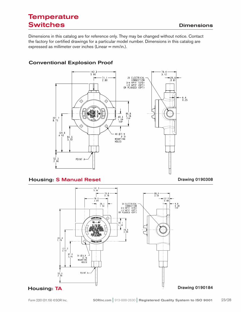
SORInc.com | 913-888-2630 | Registered Quality System to ISO 9001 23/28Form 220 (01.19) ©SOR Inc.
Conventional Explosion Proof
Dimensions in this catalog are for reference only. They may be changed without notice. Contact the factory for certified drawings for a particular model number. Dimensions in this catalog are expressed as millimeter over inches (Linear = mm/in.).
Dimensions
Housing: S Manual Reset
Housing: TA Drawing 0190184
Drawing 0190308
Temperature Switches

Registered Quality System to ISO 9001 | 913-888-2630 | SORInc.com24/28 Form 220 (01.19) ©SOR Inc.
Hermetically Sealed-Explosion Proof
Dimensions in this catalog are for reference only. They may be changed without notice. Contact the factory for certified drawings for a particular model number. Dimensions in this catalog are expressed as millimeter over inches (Linear = mm/in.).
Dimensions
ISO-9001
14685 W 105TH ST LENEXA, KS 66215 USA913-888-2630SORINC.COM
306.312.06
76.2 MIN3.00
INSTALLATIONCLEARANCE
52.32.06
168.96.65
E
C
38.11.50
34.91.38
D (TO WRENCH TIGHT)
Model Name: 0190175.ASSEM/6/0
PRODUCT CERTIFICATION DRAWINGALL DIMENSIONS ARE ±1/16 INUNLESS OTHERWISE SPECIFIED
MMLINEAR = IN
DRAWN BY
K MITCHELLCHECKED BY
M SMITHENGINEER APPROVAL
J MODIGDATE
04 APR 2012THIS DRAWING IS THE EXCLUSIVE PROPERTY OF SOR.
NO USE WHATSOEVER OF THE INFORMATION CONTAINEDHEREON, NOR REPRODUCTION IN WHOLE OR PART MAY BE
MADE WITHOUT THE EXPRESS WRITTEN PERMISSION OF SOR.
TITLE
DIM DWG 203/209 MINI-HERMET
EO NUMBER: 4991
SCALE: 0.69
DO NOT SCALE PRINT
DRAWING NUMBER REV
0190175 6
SHEET 1 OF 1DWG SIZE
B
MODEL # SALES ORDER # LINE ITEM # PURCHASE ORDER #SALES PAGE
STANDARD MODELS
BULB MODEL #
LENGTHE
A-B C D
203 182972
112.04.41
125.7 381.8 TO 4.95 15.03
9.70.38
205 3048120
124.74.91
138.4 394.5 TO 5.45 15.53
207 4572180
162.86.41
176.5 432.6 TO 6.95 17.03
209 6096240
194.67.66
208.3 464.3 TO 8.20 18.28
W/NB OPTION125, 135
RANGE ONLY
SEE ABOVEPER PROBEMODEL #
112.04.41
125.7 381.8 TO 4.95 15.03
HI-TEMP105 RANGE
SEE ABOVEPER PROBEMODEL #
148.35.84
162.1 418.1 TO 6.38 16.4616.00.63
NON-STANDARD MODEL DIMENSIONS
ELECTRICALCONNECTION1/2 NPTM
WEATHERTIGHTCOVER SCREW
FLEXIBLE SEALRETAINER
EXTERNAL GROUNDBH, BG, & JH HOUSING
POINT A
FACTORY SEALED WIRE LEADSCOLOR CODED AND MARKED
457.218.00 MINIMUM LENGTH
ARMOREDCAPILLARY
TEMPERATURESENSING BULB
POINT B BULBEXTENSION
22.40.88 HEX
1/2 NPTMGLAND NUT
1
Reset Form
Housing: AG, AH, BG, BH
Housing: BA
Drawing 0190175
Drawing 0190002
ISO-9001
14685 W 105TH ST LENEXA, KS 66215 USA913-888-2630SORINC.COM
54.72.15
306.312.06
7.10.28
37.41.47
80.73.18
54.02.13
108.04.25
60.52.38
121.04.77
52.32.06
87.33.44
220.98.70
EC
D (TO WRENCH TIGHT)Model Name: 0190002.ASSEM/7/0
PRODUCT CERTIFICATION DRAWINGALL DIMENSIONS ARE ±1/16 INUNLESS OTHERWISE SPECIFIED
MMLINEAR = IN
DRAWN BY
K MITCHELLCHECKED BY
M SMITHENGINEER APPROVAL
J MODIGDATE
14 SEP 2011THIS DRAWING IS THE EXCLUSIVE PROPERTY OF SOR.
NO USE WHATSOEVER OF THE INFORMATION CONTAINEDHEREON, NOR REPRODUCTION IN WHOLE OR PART MAY BE
MADE WITHOUT THE EXPRESS WRITTEN PERMISSION OF SOR.
TITLE
DIMENSION DRAWING203/205/207/209 BA
EO NUMBER: 5095
SCALE: 0.57
DO NOT SCALE PRINT
DRAWING NUMBER REV
0190002 7
SHEET 1 OF 1DWG SIZE
B
MODEL # SALES ORDER # LINE ITEM # PURCHASE ORDER #SALES PAGE
STANDARD MODELS
BULB MODEL #
LENGTHE
A-B C D
203 182972
112.04.41
125.7 381.8 TO 4.95 15.03
9.70.38
205 3048120
124.74.91
138.4 394.5 TO 5.45 15.53
207 4572180
162.86.41
176.5 432.6 TO 6.95 17.03
209 6096240
194.67.66
208.3 464.3 TO 8.20 18.28
W/NB OPTION125, 135
RANGE ONLY
SEE ABOVEPER PROBEMODEL #
112.04.41
125.7 381.8 TO 4.95 15.03
HI-TEMP105 RANGE
SEE ABOVEPER PROBEMODEL #
148.35.84
162.1 418.1 TO 6.38 16.4616.00.63
NON-STANDARD MODEL DIMENSIONS
1.64 FOR M20 X 1.5 F ELECTRICAL CONNECTION ADD 41.6
POINT A
CLEARANCE
FOR 6.40.25
MOUNTINGHARDWARE
ELECTRICALCONNECTION3/4 NPTF STD1/2 NPTF OPTM20 X 1.5 F OPT
FACTORY SEALED LEADSCOLOR CODED AND MARKED
457.218.00 MINIMUM LENGTH
ARMOREDCAPILLARY
BULBEXTENSION
POINT B
TEMPERATURESENSING BULB
22.40.88 HEX
1/2 NPTMGLAND NUT
1
1
1
Reset Form
Temperature Switches

SORInc.com | 913-888-2630 | Registered Quality System to ISO 9001 25/28Form 220 (01.19) ©SOR Inc.
Dimensions in this catalog are for reference only. They may be changed without notice. Contact the factory for certified drawings for a particular model number. Dimensions in this catalog are expressed as millimeter over inches (Linear = mm/in.).
Dimensions
Hermetically Sealed-Explosion Proof
ISO-9001
14685 W 105TH ST LENEXA, KS 66215 USA913-888-2630SORINC.COM
57.22.25
114.34.50
69.92.75
139.95.51
68.62.70
251.29.89
306.312.06
C
D (TO WRENCH TIGHT)
E
2X 7.10.28
MOUNTINGHOLES
27.81.09
52.32.06
9.50.38
68.02.68
PRODUCT CERTIFICATION DRAWINGALL DIMENSIONS ARE 1/16 INUNLESS OTHERWISE SPECIFIED
LINEAR = MMIN
DRAWN BY
K MITCHELLCHECKED BY
M SMITHENGINEER APPROVAL
S BOALDATE
25 AUG 2017THIS DRAWING IS THE EXCLUSIVE PROPERTY OF SOR.
NO USE WHATSOEVER OF THE INFORMATION CONTAINEDHEREON, NOR REPRODUCTION IN WHOLE OR PART MAY BE
MADE WITHOUT THE EXPRESS WRITTEN PERMISSION OF SOR.
TITLE
DIMENSION DRAWING 20X V2 DUAL HI-LO
EO NUMBER: 5387
SCALE: 0.56
DO NOT SCALE PRINT
DRAWING NUMBER REV
0190107 5
SHEET 1 OF 1DWG SIZE
B
MODEL # SALES ORDER # LINE ITEM # PURCHASE ORDER #SALES PAGE
Model Name: 0190107.ASSEM\4.1\2017-AUG-24 13:04
STANDARD MODELS
BULB MODEL #
LENGTHE
A-B C D
203 182972
112.04.41
125.74.95 TO 381.8
15.03
9.70.38
205 3048120
124.74.91
138.45.45 TO 394.5
15.53
207 4572180
162.86.41
176.56.95 TO 432.6
17.03
209 6096240
194.67.66
208.38.20 TO 464.3
18.28
W/NB OPTION125, 135
RANGE ONLY
SEE ABOVEPER PROBEMODEL #
112.04.41
125.74.95 TO 381.8
15.03
HI-TEMP105 RANGE
SEE ABOVEPER PROBEMODEL #
148.35.84
162.16.38 TO 418.1
16.4616.00.63
NON-STANDARD MODEL DIMENSIONS
NOTES:
1. ADD 6.40.25 FOR ALL NON-ALUMINUM PORTS
POINT A
FACTORY SEALEDWIRE LEADSCOLOR CODEDAND MARKED457.218.00 MIN LENGTH
ARMOREDCAPILLARY
BULBEXTENSION
POINT B
1/2 NPT(M)GLAND NUT
22.40.88 HEX
TEMPERATURESENSINGBULB
ELECTRICALCONNECTION
3/4 NPT(F) STANDARD1/2 NPT(F) OPTIONAL
SCALE 0.25
1
1
1
1
Reset Form
Housing: V2 Drawing 0190107
Temperature Switches

Registered Quality System to ISO 9001 | 913-888-2630 | SORInc.com26/28 Form 220 (01.19) ©SOR Inc.
General Purpose
Dimensions in this catalog are for reference only. They may be changed without notice. Contact the factory for certified drawings for a particular model number. Dimensions in this catalog are expressed as millimeter over inches (Linear = mm/in.).
Dimensions
Drawing 0190005
Drawing 0190008
Housing: AC (NEMA 1)
Housing: H3
Temperature Switches

SORInc.com | 913-888-2630 | Registered Quality System to ISO 9001 27/28Form 220 (01.19) ©SOR Inc.
Notes
Temperature Switches

Registered Quality System to ISO 9001 | 913-888-2630 | SORInc.com28/28 Form 220 (01.19) ©SOR Inc.
REGIONAL OFFICES
China
SOR China | Beijing, China | [email protected]
+86 (10) 5820 8767 | Fax +86 (10) 58 20 8770
Middle East
SOR Measurement & Control Equipment Trading DMCC | Dubai, UAE
[email protected] | +971 4 363 3637 | Fax + 1 913 312 3596
SOR Inc. | Lenexa, KS USA | 913-888-2630 | Fax 913-888-0767 | SORInc.com