temperature & process input · temperature & process input graphic display panel meter ....
TRANSCRIPT

DPi1701Temperature & Process Input Graphic Display Panel Meter
and Data Logger with Wireless Option
LINE GRAPH CHARTING MODE
MAIN SCREEN - INVERT MODE
HORIZONTAL BAR GRAPH MODE
e-mail: [email protected] For latest product manuals:
www.omegamanual.info
Shop online at omega.com ®
User’s Guide

Servicing North America:U.S.A.: Omega Engineering, Inc., One Omega Drive, P.O. Box 4047 Stamford, CT 06907-0047 USA
Toll-Free: 1-800-826-6342 (USA & Canada only) Customer Service: 1-800-622-2378 (USA & Canada only)
Engineering Service: 1-800-872-9436 (USA & Canada only) Tel: (203) 359-1660 Fax: (203) 359-7700 e-mail: [email protected]
Canada: Toll-Free: 1-800-826-6342 (USA & Canada only) Tel: (514) 856-6928 Fax: (514) 856-6886 e-mail: [email protected] Web: www.omega.ca
Servicing Mexico and Latin America:Mexico/ Tel: 001 (203) 359-1660 Fax: (514) 359-7700 Latin America: e-mail: [email protected] Web: mx.omega.com
Servicing Asia:China: Hotline: (+86) 800 819 0559, (+86) 400 619 0559 e-mail: [email protected] Web: cn.omega.com
Servicing Europe:France: Freephone: 0805 541 038 (France only) Tel: 01 57 32 48 17 Fax: 01 57 32 48 18 e-mail: [email protected] Web: www.omega.fr
Germany/Austria: Freephone: 0800 826 6342 (Germany only) Tel: +49 (0)7056 9398-0 Fax: +49 (0)7056 9398-29 e-mail: [email protected] Web: www.omega.de
Italy: Freephone: 800 906 907 (Italy only) Tel: +39 022 333 1521 Fax: +39 022 333 1522 e-mail: [email protected] Web: it.omega.com
Netherlands: Freephone: 0800 099 3344 (Netherlands only) Benelux Tel: +31 070 770 3815 Fax: +31 070 770 3816 e-mail: [email protected] Web: www.omega.nl
Spain: Freephone: 800 900 532 (Spain only) Tel: +34 911 776 121 Fax: +34 911 776 122 e-mail: [email protected] Web: es.omega.comUnited Kingdom: Freephone: 0800 488 488 (United Kingdom only) Tel: +44 (0)161 777 6611 Fax: +44 (0)161 777 6622 e-mail: [email protected] Web: www.omega.co.uk
omega.com [email protected]
The information contained in this document is believed to be correct, but OMEGA accepts no liability for any errors it contains, and reserves the right to alter specifications without notice.WARNING: These products are not designed for use in, and should not be used for, human applications.

i
Table of Contents
Section Page Safety Considerations .......................................................................................... iii
Section 1 - Introduction ...................................................................................... 1-1
Section 2 - Wiring Connections ......................................................................... 2-1
2.1 Front Panel ................................................................................................. 2-1
2.2 Rear Panel .................................................................................................. 2-1
Section 3 - Operation ........................................................................................... 3-1
3.1 Real Time (Run Mode) ............................................................................. 3-1
3.2 Configuration Mode ................................................................................. 3-1
3.3 Thermocouple Input Configuration ...................................................... 3-9
3.4 RTD Input Configuration .......................................................................3-10
3.5 Process Voltage Input Configuration .................................................. 3-10
3.6 Process Current Input Configuration .................................................. 3-10
3.7 Line/Bar Graph Configuration ............................................................ 3-10
3.8 Alarm Output Configuration ................................................................ 3-11
3.9 Display Screens ....................................................................................... 3-11
3.10 Max/Min Display Modes .................................................................... 3-12
3.11 Lock/Unlock Panel Meter ................................................................... 3-12
3-12 Data logging .......................................................................................... 3-12
3-13 PC Interface ........................................................................................... 3-13
Section 4 - Specifications .................................................................................... 4-1
DPi1701 Temperature & Process Input Graphic Display Panel Meter
ii
List of Figures
Figure Description Page
2-1 DPi1701 Graphic Display Front Panel & General Dimensions ... 2-1
2-2 Power & Mechanical Relay Output Connections .......................... 2-1
2-3 View of DPi1701 Back Panel With USB & Wireless Option ........ 2-2
2-4 Different Input Type Connections ................................................... 2-2
2-5 Excitation Voltage & Analog Output Connections ....................... 2-3
2-6 RS232 Connections ............................................................................. 2-3
3-1 Configuration Menu Flow Chart ..................................................... 3-1
3-2 Configuration Menu1 Flow Chart ................................................... 3-2
3-3 Configuration Menu2 Flow Chart ................................................... 3-3
3-4 Configuration Menu3 Flow Chart ....................................................3-4
3-5 Configuration Menu4 Flow Chart ................................................... 3-5
3-6 Configuration Menu5 Flow Chart ................................................... 3-6
3-7 Configuration Menu6 Flow Chart ................................................... 3-7
3-8 Configuration Menu7 Flow Chart ................................................... 3-8
3-9 Configuration Menu8 Flow Chart ................................................... 3-9
3-10 Display Screen Flow Chart ............................................................. 3-11
3-11 Max/Min Flow Chart ...................................................................... 3-12
3-12 Lock/Unlock Flow Chart ................................................................ 3-12
3-13 Data Logging Screen Flow Chart ................................................... 3-13
3-14 Download Data File Menu Screen ................................................. 3-14
3-15 Configuration Settings Screen ........................................................ 3-14
DPi1701 Temperature & Process Input Graphic Display Panel Meter
Safety ConsiderationsThis device is marked with the international caution symbol. It is important to read this manual before installing or commissioning this device as it contains important information relating to Safety and EMC (Electro-magnetic Compatibility).This instrument is a panel mount device protected in accordance with EN 61010-1:2010, electrical safety requirements for electrical equipment for measurement, control and laboratory. Installation of this instrument should be done by qualified personnel. In order to ensure safe operation, the following instructions should be followed.This instrument has no power-on switch. An external switch or circuit breaker shall be included in the building installation as a disconnecting device. It shall be marked to indicate this function, and it shall be in close proximity to the equipment within easy reach of the operator. The switch or circuit breaker shall meet the relevant requirements of IEC 947–1 and IEC 947-3 (International Electrotechnical Commission). The switch shall not be incorporated in the main supply cord.Furthermore, to provide protection against excessive energy being drawn from the main supply in case of a fault in the equipment, an over current protection device shall be installed.• Do not exceed voltage rating on the label located on the top of the instrument
housing.• Always disconnect power before changing signal and power connections.• Do not use this instrument on a work bench without its case for safety reasons.• Do not operate this instrument in flammable or explosive atmospheres.• Do not expose this instrument to rain or moisture.• Unit mounting should allow for adequate ventilation to ensure instrument
does not exceed operating temperature rating.• Use electrical wires with adequate size to handle mechanical strain and power
requirements. Install without exposing bare wire outside the connector to minimize electrical shock hazards.
• Do not touch the AC power terminal block when connected to live voltage.
EMC Considerations• Whenever EMC is an issue, always use shielded cables.• Never run signal and power wires in the same conduit.• Use signal wire connections with twisted-pair cables.• Install Ferrite Bead(s) on signal wires close to the instrument if EMC problems
persist.• For best results on RTD measurement, use shielded wiring. Connect the shield
to Pin 7 of the input terminal block.• For best RF conducted immunity on Current measurement, use Fair-Rite
#2675102002 and put the input cable through 3 turns.• For best RF conducted immunity on Voltage measurement, use Fair-Rite
#0443167251 and put the input cable through 3 turns.Failure to follow all instructions and warnings may result in injury!
iii
Safety Considerations
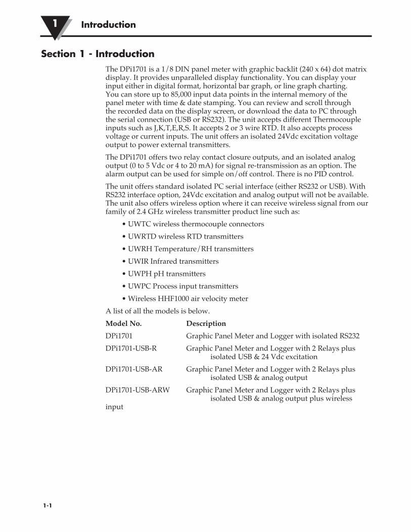
Section 1 - IntroductionThe DPi1701 is a 1/8 DIN panel meter with graphic backlit (240 x 64) dot matrix display. It provides unparalleled display functionality. You can display your input either in digital format, horizontal bar graph, or line graph charting. You can store up to 85,000 input data points in the internal memory of the panel meter with time & date stamping. You can review and scroll through the recorded data on the display screen, or download the data to PC through the serial connection (USB or RS232). The unit accepts different Thermocouple inputs such as J,K,T,E,R,S. It accepts 2 or 3 wire RTD. It also accepts process voltage or current inputs. The unit offers an isolated 24Vdc excitation voltage output to power external transmitters.The DPi1701 offers two relay contact closure outputs, and an isolated analog output (0 to 5 Vdc or 4 to 20 mA) for signal re-transmission as an option. The alarm output can be used for simple on/off control. There is no PID control.The unit offers standard isolated PC serial interface (either RS232 or USB). With RS232 interface option, 24Vdc excitation and analog output will not be available. The unit also offers wireless option where it can receive wireless signal from our family of 2.4 GHz wireless transmitter product line such as:
• UWTC wireless thermocouple connectors• UWRTD wireless RTD transmitters• UWRH Temperature/RH transmitters• UWIR Infrared transmitters• UWPH pH transmitters• UWPC Process input transmitters• Wireless HHF1000 air velocity meter
A list of all the models is below.Model No. DescriptionDPi1701 Graphic Panel Meter and Logger with isolated RS232DPi1701-USB-R Graphic Panel Meter and Logger with 2 Relays plus isolated USB & 24 Vdc excitation DPi1701-USB-AR Graphic Panel Meter and Logger with 2 Relays plus isolated USB & analog outputDPi1701-USB-ARW Graphic Panel Meter and Logger with 2 Relays plus isolated USB & analog output plus wireless input
�1-1
Introduction1
�2-1
Wiring Connections 2
Section 2 - Wiring Connections2.1 Front Panel
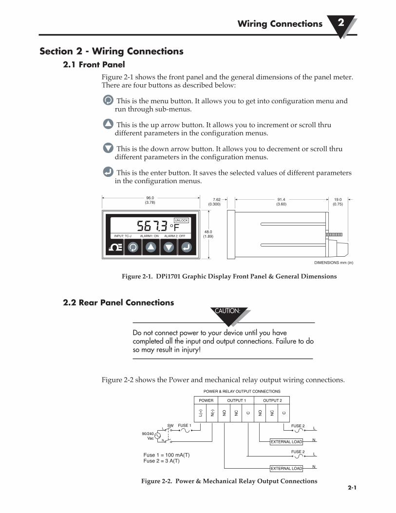
Figure 2-1 shows the front panel and the general dimensions of the panel meter. There are four buttons as described below:
This is the menu button. It allows you to get into configuration menu and run through sub-menus.
This is the up arrow button. It allows you to increment or scroll thru different parameters in the configuration menus.
This is the down arrow button. It allows you to decrement or scroll thru different parameters in the configuration menus.
This is the enter button. It saves the selected values of different parameters in the configuration menus.
Figure 2-1. DPi1701 Graphic Display Front Panel & General Dimensions
2.2 Rear Panel Connections
Do not connect power to your device until you have completed all the input and output connections. Failure to do so may result in injury!
Figure 2-2 shows the Power and mechanical relay output wiring connections.
Figure 2-2. Power & Mechanical Relay Output Connections
INPUT: TC-J ALARM1: ON ALARM 2: OFF
567.3 °FUNLOCK
96.0(3.78)
48.0(1.89)
DIMENSIONS mm (in)
91.4(3.60)
19.0(0.75)
7.62(0.300)
L(+
)
POWER
N(-
)
NO
NC C
OUTPUT 1
NO
NC C
OUTPUT 2
FUSE 1SW
90/240Vac
L
N
FUSE 2
EXTERNAL LOAD
L
N
FUSE 2 L
EXTERNAL LOAD N
POWER & RELAY OUTPUT CONNECTIONS
CAUTION:
Fuse 1 = 100 mA(T) Fuse 2 = 3 A(T)

Connection of the power source and external load to the output relays should be made by qualified personnel only. When output relay interface is made to voltages greater than 40 VAC, the interface region should be considered live and extreme care must be taken to avoid injury. Additionally, when the DPI1701 is interfaced at the output relays the preferred load is resistive. An inductive load may be used, but the maximum current values need to be derated to the values given in the specification section of this manual. In all cases, qualified personnel should ensure that the interface is properly fused to ensure further that safe operation is optimized. If there is a need to drive a motor or other inductive load at higher currents than those specified, interface may safely be made with a solid state relay, such as Omega’s SSR330DC10 or similar. Please contact Omega for support.
Figure 2-3 shows the back view of the DPi1701 panel meter. For wireless models, you need to attach the provided antenna to the mating connector on the back panel.
Figure 2-3. View of DPi1701 Back Panel With USB & Wireless Options
Figure 2-4 shows the different types of input connections such as Thermocouple, RTD (2 or 3 wires), Process voltage (0 to 10 Vdc), and Process current (0 to 20 mA).
Figure 2-4. Different Input Type Connections
Wiring Connections2
�2-2
L(+)
POWER
N(-)
OUTPUT 1
NO NC C
OUTPUT 2
1(-)
I N P U T
2(+) 3 4 5
1 2 3 4 5 6 7 8 9 106 7
8 9 10
– +
+– V
+– I
–EXC+OUT
R S 2 3 2GND RXTX
NO NC C
+–ANTENNAUSB PORT
1(-)
I N P U T
2(+) 3 4 5 6 7 8 9 10
THERMOCOUPLE CONNECTION
1(-)
I N P U T
2 3 4 5 6 7 8 9 10
RTD (100 OHMS) CONNECTION
3 WIRE
2 WIRE
1(-)
I N P U T
2 3(+) 4 5 6 7 8 9 10
PROCESS (VOLTS) CONNECTION
+–0/10V
V
1(-)
I N P U T
2 3 4(+) 5 6 7 8 9 10
PROCESS (CURRENT) CONNECTION
+–0/20mA or 4/20mA
I
– +
NOTE:
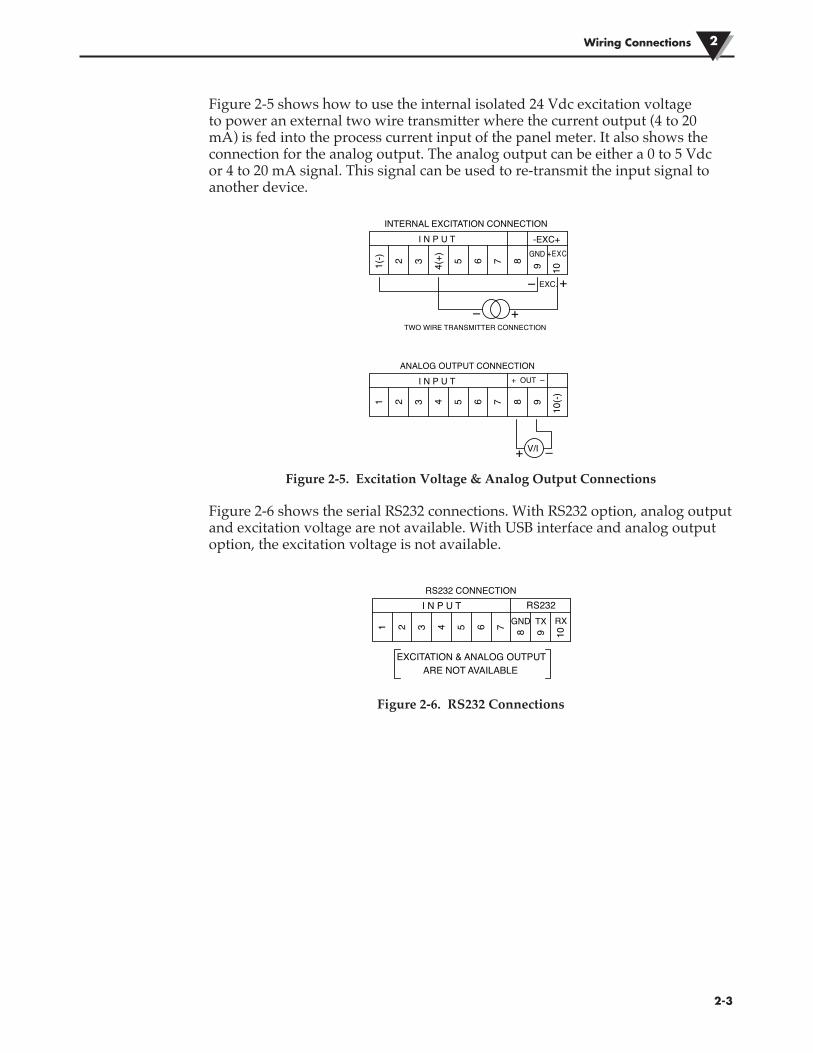
Figure 2-5 shows how to use the internal isolated 24 Vdc excitation voltage to power an external two wire transmitter where the current output (4 to 20 mA) is fed into the process current input of the panel meter. It also shows the connection for the analog output. The analog output can be either a 0 to 5 Vdc or 4 to 20 mA signal. This signal can be used to re-transmit the input signal to another device.
Figure 2-5. Excitation Voltage & Analog Output Connections
Figure 2-6 shows the serial RS232 connections. With RS232 option, analog output and excitation voltage are not available. With USB interface and analog output option, the excitation voltage is not available.
Figure 2-6. RS232 Connections
Wiring Connections 2
�2-3
1
I N P U T
2 3 4 5 6 7 8 9 10
RS232 CONNECTION
GND RXTX
EXCITATION & ANALOG OUTPUTARE NOT AVAILABLE
RS232
I N P U TINTERNAL EXCITATION CONNECTION
I N P U TANALOG OUTPUT CONNECTION
+ OUT –
+ –
-EXC+
1(-) 2 3 4(+) 5 6 7 8 9 10
GND +EXC
+
+
–
–
EXC.
TWO WIRE TRANSMITTER CONNECTION
1 2 3 4 5 6 7 8 9
10(-)
V/I

�3-1
Operation3
Section 3 - Operation3.1 Real Time (Run Mode)
This is the normal mode of operation. It displays the input parameter in real time. There is also other related information on the screen display such as Input type, status of alarm 1 and alarm 2, and status of lock/unlock. Figure 2-1 shows a typical real time display screen.
3.2 Configuration Mode
Figure 3-1 shows a typical configuration flow chart. From the Run Mode, youcan get into the Configuration mode by pressing . The configuration modehas 8 menu screens. Here is the description of each configuration menu:
Figure 3-1. Configuration Menu Flow Chart
LINE GRAPH TIME SPEED: 1 secLINE/BAR GRAPH TOP VALUE: 800.0LINE/BAR GRAPH BOTTOM VALUE: 300.0
CONFIG. MENU 1
CATEGORY: Temperature E. UNIT: °FDECIMAL POINT: xxx.xMIN. DISPLAY VALUE: -148.0
CONFIG. MENU 2
CONFIG. MENU 3
SET POINT: 450.0
INPUT TYPE: TC-J
MAX. DISPLAY VALUE: 1400.0
INPUT: TC-J ALARM1: ON ALARM 2: OFF
°FUNLOCK
PRESS
PRESS
PRESS
ENTER BUTTON. SAVE SELECTION AND RUN THROUGHENTRIES OF A CONFIG. SUB-MENU.
INCREMENT PARAMETER VALUE/SELECTION OF AN ENTRY.
DECREMENT PARAMETER VALUE/SELECTION OF AN ENTRY.
REAL TIME(RUN MODE)
DISPLAY SPAN ADJUST: 0OUTPUT TYPE: 0-5VDISPLAY MODE: NORMAL
CONFIG. MENU 5DISPLAY ZERO ADJUST: 10 PRESS
DEAD BAND: 10.0
[ALARM 1]STATUS: ENABLED
UNLATCHLOW
CONFIG. MENU 4
SET POINT: 700.0
PRESS
DEAD BAND: 10.0
[ALARM 2]STATUS: ENABLED
LATCHHIGH568.3°F
CONFIG. MENU 6
CURRENT DATE: 01/03/2012TIME FORMAT: 12 Hour MM/DD/YYYYLOG MODE: STOP WHEN FULL
CURRENT TIME: 03:53:45 PM
PRESS
PRESS
CONFIG. MENU 7
START LOGGINGKEY PRESS
STOP LOGGINGKEY PRESS
PRESS
CONFIG. MENU 8
TIME OUT: 6 WIRELESS CHANNEL: 12WIRELESS NETWORK ID: 13106
TRANS ADDR: 1 RECEIVER ADDR: 0
PRESSNOTE: CONFIG MENU 8 SHOWSUP ONLY WHEN INPUT TYPE ISSELECTED AS WIRELESS.
567.3
Operation 3
�3-2
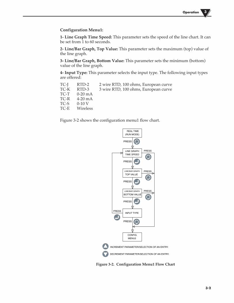
Configuration Menu1:1- Line Graph Time Speed: This parameter sets the speed of the line chart. It can be set from 1 to 60 seconds.2- Line/Bar Graph, Top Value: This parameter sets the maximum (top) value of the line graph.3- Line/Bar Graph, Bottom Value: This parameter sets the minimum (bottom) value of the line graph.4- Input Type: This parameter selects the input type. The following input types are offered:TC-J RTD-2 2 wire RTD, 100 ohms, European curve TC-K RTD-3 3 wire RTD, 100 ohms, European curve TC-T 0-20 mA TC-R 4-20 mA TC-S 0-10 V TC-E Wireless
Figure 3-2 shows the configuration menu1 flow chart.
Figure 3-2. Configuration Menu1 Flow Chart
LINE GRAPHTIME SPEED
PRESS
LINE/BAR GRAPH
TOP VALUE
PRESS
BOTTOM VALUE
PRESS
INPUT TYPEPRESS
PRESS
REAL TIME(RUN MODE)
PRESS
PRESS
PRESS
PRESS
CONFIG.MENU2
INCREMENT PARAMETER/SELECTION OF AN ENTRY.
DECREMENT PARAMETER/SELECTION OF AN ENTRY.
LINE/BAR GRAPH

Configuration Menu2:1. Category: You can select the category of measurement like Temperature,
Pressure, Power, pH, Humidity, etc.2. Engineering Unit: You can set the Engineering unit for the selected category.3. Decimal Point: You can set the decimal point for the input display reading.4. Minimum Display Value: You can set the minimum display range for the
input.5. Maximum Display Value: You can set the maximum display range for the
input.Figure 3-3 shows the configuration menu2 flow chart.
Figure 3-3. Configuration Menu2 Flow Chart
Operation3
�3-3
ENGINEERING
CATEGORY
UNIT
PRESS
PRESS
DECIMAL POINT
PRESS
VALUE
PRESS
PRESS
PRESS
CONFIG.MENU2
PRESS
PRESS
PRESS
PRESS
PRESS
CONFIG.MENU3
INCREMENT PARAMETER/SELECTION OF AN ENTRY.
DECREMENT PARAMETER/SELECTION OF AN ENTRY.
MIN. DISPLAY
VALUEMAX. DISPLAY

Configuration Menu3:1. Set Point: You can set the 1st alarm set point to anywhere within the display
range.2. Dead Band: You can set the dead band for the 1st relay alarm.3. Status: You can enable or disable the 1st alarm. If the relay is latched
previously, disabling/enabling the alarm will reset the relay.If the alarm is enabled, you can set the relay for latch/unlatch operation. You can set the relay for either low or high alarm.Figure 3-4 shows the configuration menu3 flow chart.
Figure 3-4. Configuration Menu3 Flow Chart
Operation 3
�3-4
ALARMSET POINT 1
PRESS
DEAD BAND
PRESS
ENABLED
DISABLED
PRESS
PRESS
PRESS
PRESS
PRESS
PRESS
INCREMENT PARAMETER/SELECTION OF AN ENTRY.
DECREMENT PARAMETER/SELECTION OF AN ENTRY.
CONFIG.MENU3
CONFIG.MENU4
UNLATCH/LATCH
HIGH/LOW
STATUS

Configuration Menu4:1. Set Point: You can set the 2nd alarm set point to anywhere within the display
range.2. Dead Band: You can set the dead band for the 2nd relay alarm.3. Status: You can enable or disable the 2nd alarm. If the relay is latched
previously, disabling/enabling the alarm will reset the relay.If the alarm is enabled, you can set the relay for latch/unlatch operation. You can set the relay for either low or high alarm.Figure 3-5 shows the configuration menu4 flow chart.
Figure 3-5. Configuration Menu4 Flow Chart
Operation3
�3-5
ALARM 2SET POINT
PRESS
DEAD BAND
PRESS
ENABLED
DISABLED
PRESS
PRESS
PRESS
PRESS
PRESS
PRESS
INCREMENT PARAMETER/SELECTION OF AN ENTRY.
DECREMENT PARAMETER/SELECTION OF AN ENTRY.
CONFIG.MENU4
CONFIG.MENU5
UNLATCH/LATCH
HIGH/LOW
STATUS

Configuration Menu5:1. Display Zero Adjust: You can adjust the zero of your display reading either
positive or negative (Up to 9999 counts). A Pop up window displays the current process value as you adjust the zero. For example if temperature display is 72.5°F, four positive zero adjust counts will change the display to 72.9°F. Four negative zero adjust counts will change the display to 72.1°F.
2. Display Span Adjust: You can adjust the span of your display range either positive or negative (Up to 9999 counts). A Pop up window displays the process value as you adjust the span.
3. Output Type: You can select the analog output type either 0-5 Vdc or 4-20 mA. The analog output corresponds to the input display range. Here is an example:
Input Type: TC-K Min. Display Value: 0 Max. Display Value: 500 Analog Output: 0-5 Vdc
4. Display Mode: You can set the display screen to Normal or Invert, depending on the screen visibility.
Figure 3-6 shows the configuration menu5 flow chart.
Figure 3-6. Configuration Menu5 Flow Chart
Operation 3
�3-6
DISPLAY ZEROADJUST
PRESS
PRESS
TYPE
PRESS
PRESS
PRESS
CONFIG.MENU5
PRESS
PRESS
PRESS
PRESS
CONFIG.MENU6
INCREMENT PARAMETER/SELECTION OF AN ENTRY.
DECREMENT PARAMETER/SELECTION OF AN ENTRY.
OUTPUT
DISPLAY
DISPLAY SPANADJUST
MODE

Configuration Menu6:1. Current Time: You can set the current time. It can be set as either AM/PM (12
Hour) or Military time (24 Hour).2. Current Date: You can set the current date. The date format can be selected.
The default is MM/DD/YYYY.3. Time Format: You can set the time & date formats. The time can be set as 12
Hour/24 Hour. The date format can be set to MM/DD/YYYY, DD/MM/YYYY, or YYYY/MM/DD.
The Time & Date settings will be lost when removing main power.
4. Log Mode: You can set the logging mode. It can be set to “Stop When Full” meaning data recording will stop when it reaches the end of the internal memory, or “Circular Buffer” meaning that once it reaches the end of the memory, data recording will continue and will overwrite the oldest data in the memory.
Figure 3-7 shows the configuration menu6 flow chart.
Figure 3-7. Configuration Menu6 Flow Chart
Operation3
�3-7
SET CURRENTTIME
PRESS
PRESS
FORMAT
PRESS
PRESS
PRESS
CONFIG.MENU6
PRESS
PRESS
PRESS
PRESS
CONFIG.MENU7
INCREMENT PARAMETER/SELECTION OF AN ENTRY.
DECREMENT PARAMETER/SELECTION OF AN ENTRY.
SET TIME
SET LOGGING
SET CURRENTDATE
MODE
NOTE:
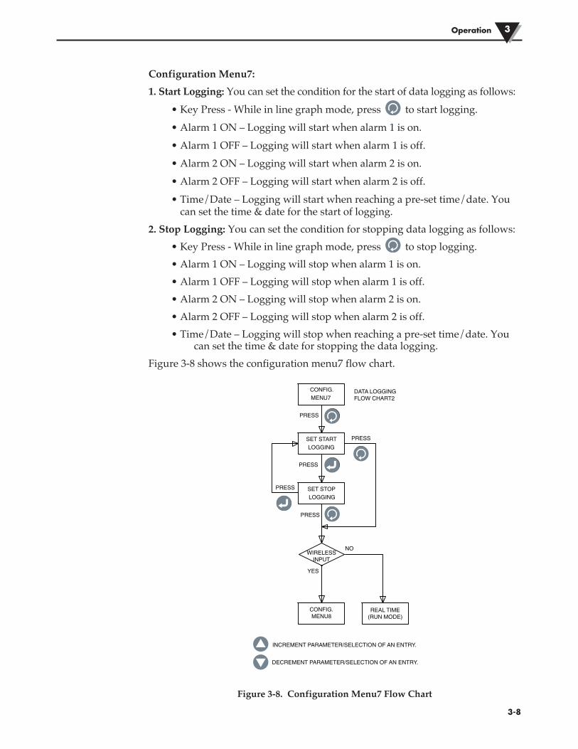
Configuration Menu7:1. Start Logging: You can set the condition for the start of data logging as follows:
• Key Press - While in line graph mode, press to start logging.• Alarm 1 ON – Logging will start when alarm 1 is on.• Alarm 1 OFF – Logging will start when alarm 1 is off.• Alarm 2 ON – Logging will start when alarm 2 is on.• Alarm 2 OFF – Logging will start when alarm 2 is off.• Time/Date – Logging will start when reaching a pre-set time/date. You
can set the time & date for the start of logging.2. Stop Logging: You can set the condition for stopping data logging as follows:
• Key Press - While in line graph mode, press to stop logging.• Alarm 1 ON – Logging will stop when alarm 1 is on.• Alarm 1 OFF – Logging will stop when alarm 1 is off.• Alarm 2 ON – Logging will stop when alarm 2 is on.• Alarm 2 OFF – Logging will stop when alarm 2 is off.• Time/Date – Logging will stop when reaching a pre-set time/date. You
can set the time & date for stopping the data logging.Figure 3-8 shows the configuration menu7 flow chart.
Figure 3-8. Configuration Menu7 Flow Chart
Operation 3
�3-8
CONFIG.MENU8
REAL TIME(RUN MODE)
WIRELESSINPUT
YES
NO
SET STARTLOGGING
PRESS
PRESS
PRESS
PRESS
CONFIG.MENU7
PRESS
SET STOPLOGGING
INCREMENT PARAMETER/SELECTION OF AN ENTRY.
DECREMENT PARAMETER/SELECTION OF AN ENTRY.
DATA LOGGINGFLOW CHART2
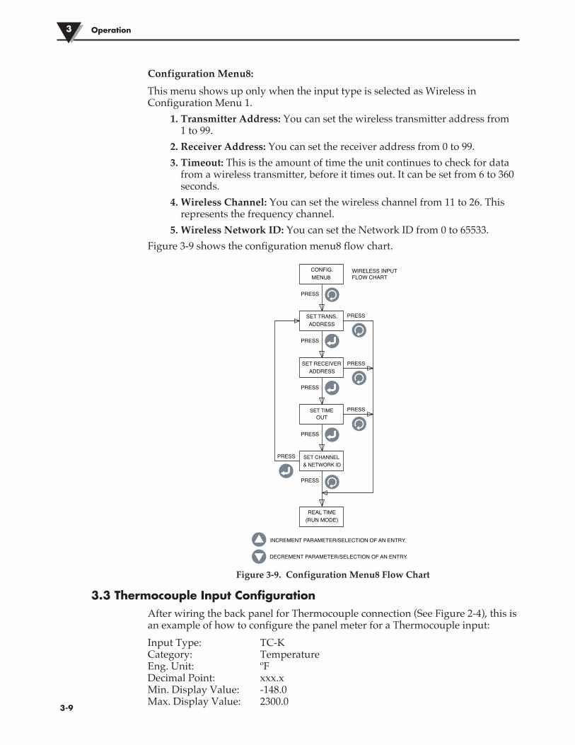
Configuration Menu8:This menu shows up only when the input type is selected as Wireless in Configuration Menu 1.
1. Transmitter Address: You can set the wireless transmitter address from 1 to 99.
2. Receiver Address: You can set the receiver address from 0 to 99.3. Timeout: This is the amount of time the unit continues to check for data
from a wireless transmitter, before it times out. It can be set from 6 to 360 seconds.
4. Wireless Channel: You can set the wireless channel from 11 to 26. This represents the frequency channel.
5. Wireless Network ID: You can set the Network ID from 0 to 65533.Figure 3-9 shows the configuration menu8 flow chart.
Figure 3-9. Configuration Menu8 Flow Chart
3.3 Thermocouple Input ConfigurationAfter wiring the back panel for Thermocouple connection (See Figure 2-4), this is an example of how to configure the panel meter for a Thermocouple input:Input Type: TC-K Category: Temperature Eng. Unit: ºF Decimal Point: xxx.x Min. Display Value: -148.0 Max. Display Value: 2300.0
Operation3
�3-9
SET TRANS.ADDRESS
PRESS
PRESS
OUT
PRESS
PRESS
PRESS
CONFIG.MENU8
PRESS
PRESS
PRESS
PRESS
REAL TIME(RUN MODE)
INCREMENT PARAMETER/SELECTION OF AN ENTRY.
DECREMENT PARAMETER/SELECTION OF AN ENTRY.
SET TIME
SET CHANNEL
SET RECEIVERADDRESS
& NETWORK ID
WIRELESS INPUTFLOW CHART

3.4 RTD Input ConfigurationAfter wiring the back panel for RTD connection (See Figure 2-4), this is an example of how to configure the panel meter for an RTD input:Input Type: RTD-3 Category: Temperature Eng. Unit: ºF Decimal Point: xxx.x Min. Display Value: -328.0 Max. Display Value: 1562.0
3.5 Process Voltage Input ConfigurationAfter wiring the back panel for Process Voltage connection (See Figure 2-4), this is an example of how to configure the panel meter for a Process Voltage input:Input Type: 0-5 V Category: Flow Eng. Unit: GPM Decimal Point: xxxx Min. Display Value: 0 Max. Display Value: 4500
3.6 Process Current Input ConfigurationAfter wiring the back panel for Process Current connection (See Figure 2-4), this is an example of how to configure the panel meter for a Process Current input:Input Type: 4-20 mA Category: Pressure Eng. Unit: PSI Decimal Point: xxx.x Min. Display Value: 0.0 Max. Display Value: 100.0
3.7 Line/Bar Graph ConfigurationHere is an example of configuring the panel meter for line or horizontal bar graph displays:Line Graph Time Speed: 1 sec Line/Bar Graph Top value: 800.0 Line/Bar Graph Bottom Value: 300.0The line graph time speed is the time interval the line graph gets updated. The same time speed is used for data logging time interval. The line graph bar is the average of all the input samples during the time interval (Time Speed). The line/bar graph top and bottom values are the scaling for the line and horizontal bar graph.
Operation 3
�3-10
3.8 Alarm Output ConfigurationHere is an example of configuration at the panel meter for alarm outputs (assuming thermocouple input):[Alarm 1] Set Point: 450.0 Dead Band: 10.0 Status: Enabled Unlatch Low[Alarm 2] Set Point: 700.0 Dead Band: 10.0 Status: Enabled Latch HighWhen an alarm is disabled, the other selections (Latch/ Unlatch, High/Low) are not displayed.
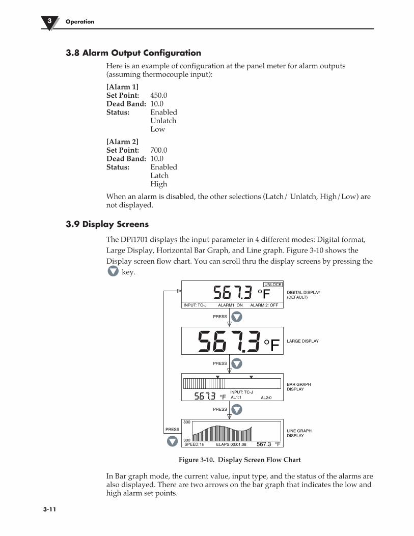
3.9 Display Screens
The DPi1701 displays the input parameter in 4 different modes: Digital format, Large Display, Horizontal Bar Graph, and Line graph. Figure 3-10 shows the Display screen flow chart. You can scroll thru the display screens by pressing the
key.
Figure 3-10. Display Screen Flow Chart
In Bar graph mode, the current value, input type, and the status of the alarms are also displayed. There are two arrows on the bar graph that indicates the low and high alarm set points.
Operation3
�3-11
INPUT: TC-J ALARM1: ON ALARM 2: OFF
°FUNLOCK
°FINPUT: TC-J
AL2:0AL1:1
PRESS
PRESS
800
300SPEED:1s 567.3 °FELAPS:00:01:08
PRESS
PRESS
DIGITAL DISPLAY(DEFAULT)
BAR GRAPHDISPLAY
LINE GRAPHDISPLAY
°F LARGE DISPLAY
567.3
567.3
567.3
Operation 3
�3-12
In line graph mode, the current value, time speed, and elapsed time (HH:MM:SS) are also displayed. The elapsed time advances per the time speed. For example if the time speed is 10 seconds, the elapsed time advances every 10 seconds.
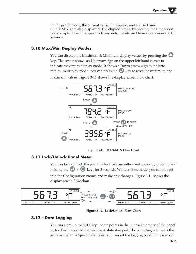
3.10 Max/Min Display Modes
You can display the Maximum & Minimum display values by pressing the key. The screen shows an Up arrow sign on the upper left hand corner to indicate maximum display mode. It shows a Down arrow sign to indicate minimum display mode. You can press the key to reset the minimum and
maximum values. Figure 3-11 shows the display screen flow chart.
Figure 3-11. MAX/MIN Flow Chart
3.11 Lock/Unlock Panel Meter
You can lock/unlock the panel meter from un-authorized access by pressing and holding the + keys for 3 seconds. While in lock mode, you can not get
into the Configuration menus and make any changes. Figure 3-12 shows the display screen flow chart.
Figure 3-12. Lock/Unlock Flow Chart
3.12 – Data Logging
You can store up to 85,000 input data points in the internal memory of the panel meter. Each recorded data is time & date stamped. The recording interval is the same as the Time Speed parameter. You can set the logging condition based on
INPUT: TC-J ALARM1: ON ALARM 2: OFF
°FUNLOCK
PRESS
PRESS
PRESS
DIGITAL DISPLAY(DEFAULT)
MAX. DISPLAYMODE
MIN. DISPLAYMODE
INPUT: TC-J ALARM1: ON ALARM 2: OFF
°FUNLOCK
INPUT: TC-J ALARM1: ON ALARM 2: OFF
°FUNLOCK
PRESS TO RESET
MIN/MAX VALUES
567.3
784.2
395.6
INPUT: TC-J ALARM1: ON ALARM 2: OFF
°FUNLOCK
PRESS & HOLDFOR 3 SECONDS
INPUT: TC-J ALARM1: ON ALARM 2: OFF
°FLOCK
+567.3 567.3
Operation3
�3-13
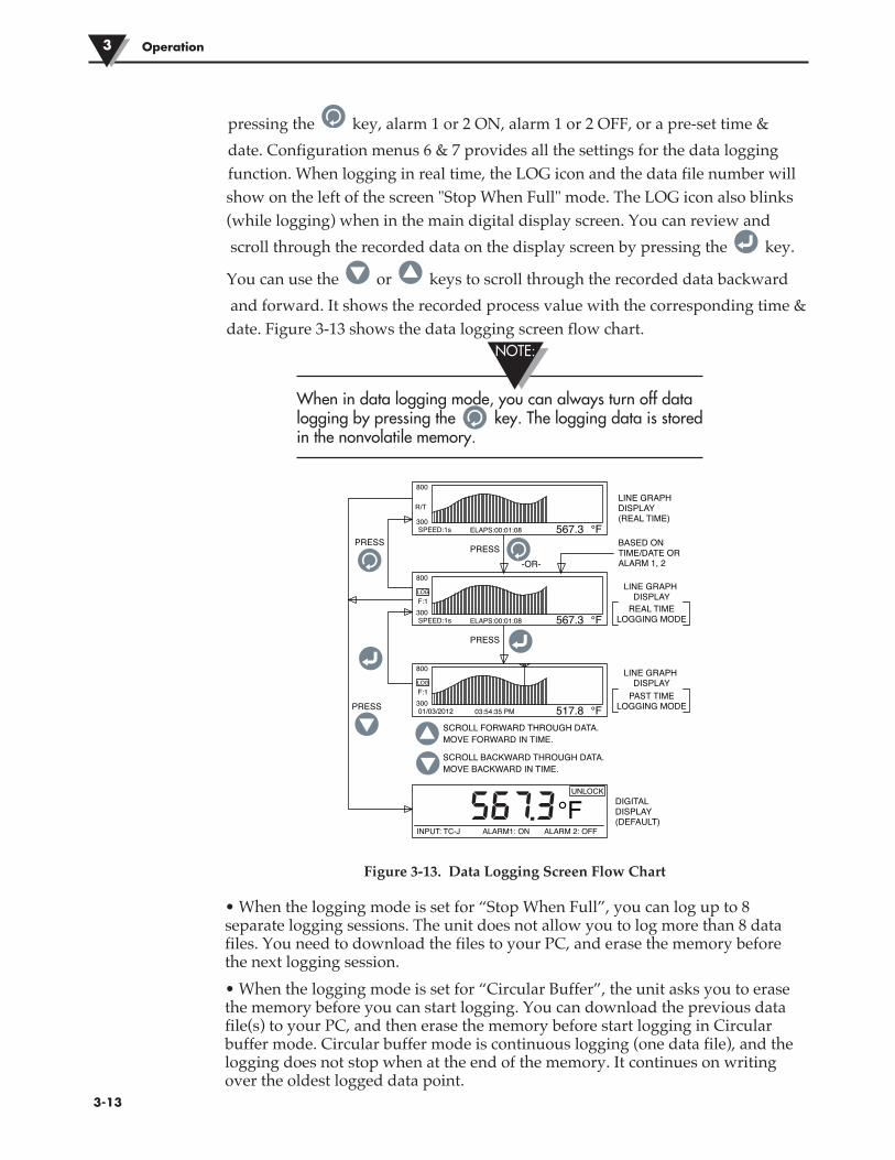
pressing the key, alarm 1 or 2 ON, alarm 1 or 2 OFF, or a pre-set time &date. Configuration menus 6 & 7 provides all the settings for the data logging function. When logging in real time, the LOG icon and the data file number will show on the left of the screen "Stop When Full" mode. The LOG icon also blinks (while logging) when in the main digital display screen. You can review and scroll through the recorded data on the display screen by pressing the key.
You can use the or keys to scroll through the recorded data backward and forward. It shows the recorded process value with the corresponding time & date. Figure 3-13 shows the data logging screen flow chart.
When in data logging mode, you can always turn off data logging by pressing the key. The logging data is stored in the nonvolatile memory.
Figure 3-13. Data Logging Screen Flow Chart
• When the logging mode is set for “Stop When Full”, you can log up to 8 separate logging sessions. The unit does not allow you to log more than 8 data files. You need to download the files to your PC, and erase the memory before the next logging session.• When the logging mode is set for “Circular Buffer”, the unit asks you to erase the memory before you can start logging. You can download the previous data file(s) to your PC, and then erase the memory before start logging in Circular buffer mode. Circular buffer mode is continuous logging (one data file), and the logging does not stop when at the end of the memory. It continues on writing over the oldest logged data point.
NOTE:
PRESSPRESS
PRESS
PRESS
LINE GRAPH DISPLAY(REAL TIME)
LINE GRAPH DISPLAY
LINE GRAPH DISPLAY
REAL TIMELOGGING MODE
PAST TIMELOGGING MODE
SCROLL FORWARD THROUGH DATA.MOVE FORWARD IN TIME.
SCROLL BACKWARD THROUGH DATA.MOVE BACKWARD IN TIME.
DIGITAL DISPLAY(DEFAULT)
BASED ONTIME/DATE ORALARM 1, 2
800
300SPEED:1s 567.3 °FELAPS:00:01:08
R/T
800
300SPEED:1s 567.3 °FELAPS:00:01:08
LOGF:1
800
30001/03/2012 517.8 °F03:54:35 PM
LOGF:1
-OR-
INPUT: TC-J ALARM1: ON ALARM 2: OFF
°FUNLOCK
567.3

�3-14
3.13 – PC InterfaceYou can perform the following tasks using the PC application software: 1. Download & Erase the recorded data from the panel meter 2. Read & Change the panel meter configuration settingsFigure 3-14 shows the menu screen for downloading the recorded data. You can download up to 8 data files from the panel meter by highlighting the file number and clicking “Save Selected File” button. You can save each data file as a .csv extension to be imported into Excel spread sheet.You can also erase all the data files from the panel meter by clicking the “Erase All From Device” button.
When changing panel meter configuration settings from the PC, make sure the panel meter is not in the configuration mode and is in running mode.
Figure 3-14. Download Data File Menu Screen
NOTE:
Operation 3
�3-15
Operation3
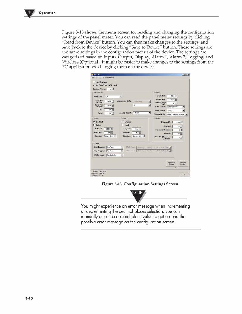
Figure 3-15 shows the menu screen for reading and changing the configuration settings of the panel meter. You can read the panel meter settings by clicking “Read from Device” button. You can then make changes to the settings, and save back to the device by clicking “Save to Device” button. These settings are the same settings in the configuration menus of the device. The settings are categorized based on Input/ Output, Display, Alarm 1, Alarm 2, Logging, and Wireless (Optional). It might be easier to make changes to the settings from the PC application vs. changing them on the device.
Figure 3-15. Configuration Settings Screen
You might experience an error message when incrementing or decrementing the decimal places selection, you can manually enter the decimal place value to get around the possible error message on the configuration screen.
NOTE:

PC Commands: The following is a list of PC commands to communicate with the device.
ENQ<CR> Show unit ID and Firmware version
ERASE Erase entire internal EEPROM memory, reset internal file system EXAMPLE: Command Response ERASE<CR> Erased<CRLF>
AMPM Display or Set the time format to 24/12 hours. [0 = 24 Hr, 1 = 12 Hr] EXAMPLE: Command Response Display Time format AMPM<CR> 12 Hr<CRLF> Set Time to 24 Hr AMPM 0<CR> 24 Hr<CRLF> Set Time to 12 Hr AMPM 1<CR> 12 Hr<CRLF>
TIME Display or Set the Time [AMPM set to 12 Hr] EXAMPLE: Command Response Display Time TIME<CR> 01:00:00 PM<CRLF> Set Time to 15 TIME 15<CR> 03:00:00 PM<CRLF> Set Time to 15:30 TIME 15 30<CR> 03:30:00 PM<CRLF> Set Time to 15:30:10 TIME 15 30 10<CR> 03:30:10 PM<CRLF>
Display or Set the Time [AMPM set to 24 Hr] EXAMPLE: Command Response Display Time TIME<CR> 13:00:00<CRLF> Set Time to 15 TIME 15<CR> 15:00:00<CRLF> Set Time to 15:30 TIME 15 30<CR> 15:30:00<CRLF> Set Time to 15:30:10 TIME 15 30 10<CR> 15:30:10<CRLF>
DATE Display or Set the Date EXAMPLE: Command Response Display Date DATE<CR> 01/05/2012<CRLF> Set Date to 06/04/2012 DATE 06 04 2012<CR> 06/04/2012<CRLF> Set Date to 05 DATE 05<CR> 05/04/2012<CRLF> Set Date to 06/12 DATE 06 12<CR> 06/12/2012<CRLF>
XD Display process value, Engineering unit, input type, lock status, and alarms status EXAMPLE: Command Response XD<CR> -103°F TC-K UNLOCK 0 1<CRLF> In this example: Process value: -103 Engineering Unit: °F Input Type: TC-KR Lock Status: UNLOCK Alarm 1 Status: 0, meaning OFF Alarm 2 Status: 1, meaning ON
Note: <CR> means carriage return, <CRLF> means carriage return & Line feed. If there is a space in the command structure, you need to follow and can not eliminate.
Operation 3
�3-16�3-16

Section 4 - SpecificationsGENERAL Thermocouple Accuracy Type J: 0.5ºC (0.9ºF) Type K: 0.5ºC (0.9ºF) Type E: 0.5°C (0.9°F) Type T: 0.5ºC (0.9ºF) Type R & S: 2.5°C (4.5°F) or 0.5% of full scaleThermocouple Range Type J: -100 to 760ºC (-148 to 1400ºF) Type K: -100 to 1260ºC (-148 to 2300ºF) Type E: -200 to 849°C (-328 to 1560°F) Type T: -200 to 400ºC (-328 to 752ºF) Type R & S: 100 to 1760ºC (212 to 3200ºF)Thermocouple Warm up Period: 45 minutesThermocouple Zero Drift: 0.06°C/°COpen Thermocouple Detection: Up scaleThermocouple Lead Resistance: 100 ohms max.RTD: 100 ohms Platinum, 2 or 3 wire, 0.00385 curveRTD Accuracy: 0.5ºC (0.9ºF)RTD Range: -200 to 850ºC (-328 to 1562ºF)Open RTD Detection: Up scaleProcess (Voltage or current) Input Accuracy: 0.1% of RdgVoltage Input Range: 0 to 10 VdcCurrent Input Range: 0 to 20 mA and 4 to 20 mASampling Rate: 4 samples per second Decimal Selection: None, 0.1 – Temperature input None, 0.1, 0.01, 0.001 – Process inputPC Interface: Isolated USB or RS232, 9600 Baud Rate, 8-Bit
data, No Parity, 1 Stop bitData Logging Recorded Data: Up to 85,000 data points Maximum Data Files: 8 - Only in Stop when Full Logging Mode Logging Mode: Stop When Full or Circular Buffer Logging Start: Press Key, Alarm 1/2 ON, Alarm 1/2 OFF, Time/Date Logging Stop: Press Key, Alarm 1/2 ON, Alarm 1/2 OFF,
Time/Date
4-1
Specifications4
4-1
Specifications 4
4-2
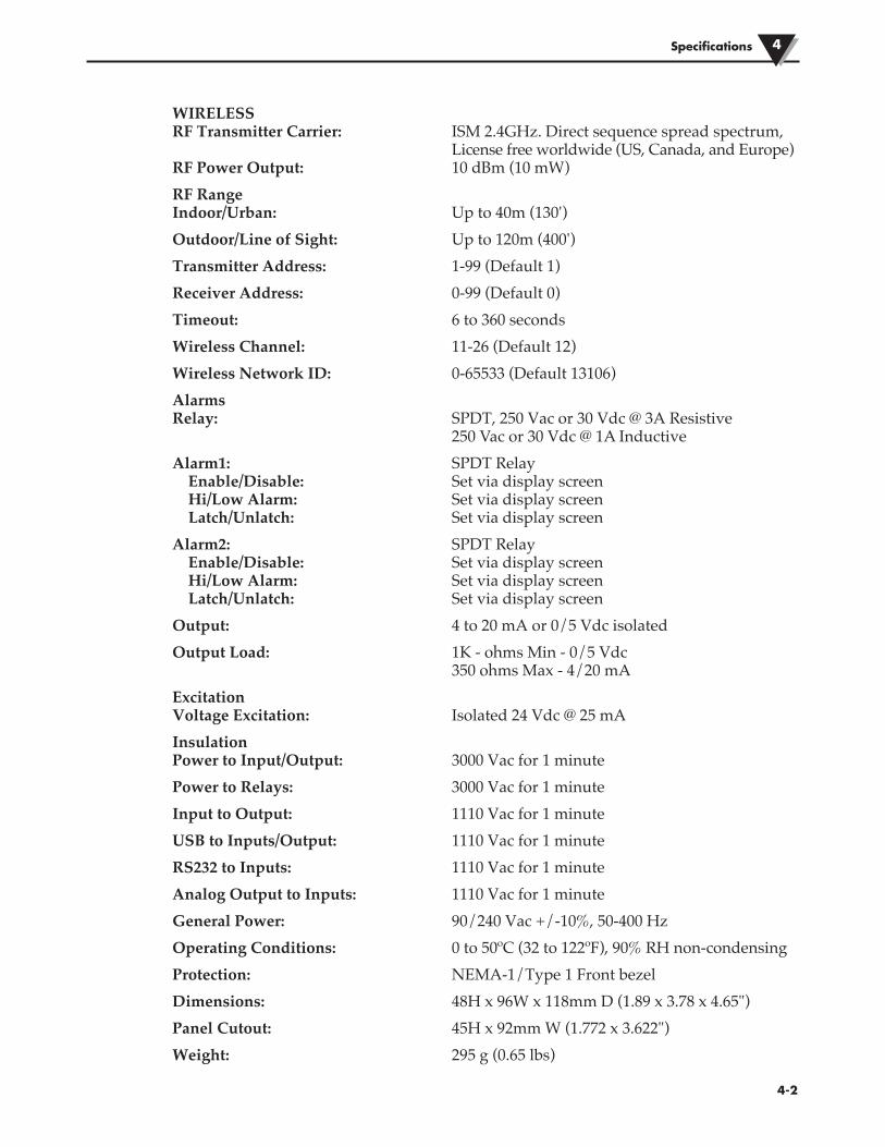
WIRELESS RF Transmitter Carrier: ISM 2.4GHz. Direct sequence spread spectrum, License free worldwide (US, Canada, and Europe) RF Power Output: 10 dBm (10 mW)RF Range Indoor/Urban: Up to 40m (130')Outdoor/Line of Sight: Up to 120m (400')Transmitter Address: 1-99 (Default 1)Receiver Address: 0-99 (Default 0)Timeout: 6 to 360 secondsWireless Channel: 11-26 (Default 12)Wireless Network ID: 0-65533 (Default 13106)Alarms Relay: SPDT, 250 Vac or 30 Vdc @ 3A Resistive 250 Vac or 30 Vdc @ 1A InductiveAlarm1: SPDT Relay Enable/Disable: Set via display screen Hi/Low Alarm: Set via display screen Latch/Unlatch: Set via display screenAlarm2: SPDT Relay Enable/Disable: Set via display screen Hi/Low Alarm: Set via display screen Latch/Unlatch: Set via display screenOutput: 4 to 20 mA or 0/5 Vdc isolatedOutput Load: 1K - ohms Min - 0/5 Vdc 350 ohms Max - 4/20 mA Excitation Voltage Excitation: Isolated 24 Vdc @ 25 mAInsulation Power to Input/Output: 3000 Vac for 1 minutePower to Relays: 3000 Vac for 1 minuteInput to Output: 1110 Vac for 1 minuteUSB to Inputs/Output: 1110 Vac for 1 minuteRS232 to Inputs: 1110 Vac for 1 minuteAnalog Output to Inputs: 1110 Vac for 1 minuteGeneral Power: 90/240 Vac +/-10%, 50-400 HzOperating Conditions: 0 to 50ºC (32 to 122ºF), 90% RH non-condensingProtection: NEMA-1/Type 1 Front bezelDimensions: 48H x 96W x 118mm D (1.89 x 3.78 x 4.65")Panel Cutout: 45H x 92mm W (1.772 x 3.622")Weight: 295 g (0.65 lbs)
WARRANTY/DISCLAIMEROMEGA ENGINEERING, INC. warrants this unit to be free of defects in materials and workmanship for a period of 60 months from date of purchase. OMEGA’s WARRANTY adds an additional one (1) month grace period to the normal five (5) year product warranty to cover handling and shipping time. This ensures that OMEGA’s customers receive maximum coverage on each product. If the unit malfunctions, it must be returned to the factory for evaluation. OMEGA’s Customer Service Department will issue an Authorized Return (AR) number immediately upon phone or written request. Upon examination by OMEGA, if the unit is found to be defective, it will be repaired or replaced at no charge. OMEGA’s WARRANTY does not apply to defects resulting from any action of the purchaser, including but not limited to mishandling, improper interfacing, operation outside of design limits, improper repair, or unauthorized modification. This WARRANTY is VOID if the unit shows evidence of having been tampered with or shows evidence of having been damaged as a result of excessive corrosion; or current, heat, moisture or vibration; improper specification; misapplication; misuse or other operating conditions outside of OMEGA’s control. Components in which wear is not warranted, include but are not limited to contact points, fuses, and triacs.OMEGA is pleased to offer suggestions on the use of its various products. However, OMEGA neither assumes responsibility for any omissions or errors nor assumes liability for any damages that result from the use of its products in accordance with information provided by OMEGA, either verbal or written. OMEGA warrants only that the parts manufactured by the company will be as specified and free of defects. OMEGA MAKES NO OTHER WARRANTIES OR REPRESENTATIONS OF ANY KIND WHATSOEVER, EXPRESSED OR IMPLIED, EXCEPT THAT OF TITLE, AND ALL IMPLIED WARRANTIES INCLUDING ANY WARRANTY OF MERCHANTABILITY AND FITNESS FOR A PARTICULAR PURPOSE ARE HEREBY DISCLAIMED. LIMITATION OF LIABILITY: The remedies of purchaser set forth herein are exclusive, and the total liability of OMEGA with respect to this order, whether based on contract, warranty, negligence, indemnification, strict liability or otherwise, shall not exceed the purchase price of the component upon which liability is based. In no event shall OMEGA be liable for consequential, incidental or special damages.CONDITIONS: Equipment sold by OMEGA is not intended to be used, nor shall it be used: (1) as a “Basic Component” under 10 CFR 21 (NRC), used in or with any nuclear installation or activity; or (2) in medical applications or used on humans. Should any Product(s) be used in or with any nuclear installation or activity, medical application, used on humans, or misused in any way, OMEGA assumes no responsibility as set forth in our basic WARRANTY/DISCLAIMER language, and, additionally, purchaser will indemnify OMEGA and hold OMEGA harmless from any liability or damage whatsoever arising out of the use of the Product(s) in such a manner.
OMEGA’s policy is to make running changes, not model changes, whenever an improvement is possible. This affords our customers the latest in technology and engineering.OMEGA is a registered trademark of OMEGA ENGINEERING, INC. Patent Pending© Copyright 2013 OMEGA ENGINEERING, INC. All rights reserved. This document may not be copied, photocopied, reproduced, translated, or reduced to any electronic medium or machine-readable form, in whole or in part, without the prior written consent of OMEGA ENGINEERING, INC.
FOR WARRANTY RETURNS, please have the following information available BEFORE contacting OMEGA:1. Purchase Order number under which the product
was PURCHASED,2. Model and serial number of the product under
warranty, and3. Repair instructions and/or specific problems relative to the product.
FOR NON-WARRANTY REPAIRS, consult OMEGA for current repair charges. Have the following information available BEFORE contacting OMEGA:1. Purchase Order number to cover the COST of the repair,2. Model and serial number of the product, and3. Repair instructions and/or specific problems relative to the product.
RETURN REQUESTS/INQUIRIESDirect all warranty and repair requests/inquiries to the OMEGA Customer Service Department. BEFORE RETURNING ANY PRODUCT(S) TO OMEGA, PURCHASER MUST OBTAIN AN AUTHORIZED RETURN (AR) NUMBER FROM OMEGA’S CUSTOMER SERVICE DEPARTMENT (IN ORDER TO AVOID PROCESSING DELAYS). The assigned AR number should then be marked on the outside of the return package and on any correspondence.The purchaser is responsible for shipping charges, freight, insurance and proper packaging to prevent breakage in transit.

M5021/0613
Where Do I Find Everything I Need for Process Measurement and Control?
OMEGA…Of Course!Shop online at omega.com ®
TEMPERATUREMU Thermocouple, RTD & Thermistor Probes, Connectors, Panels & Assemblies MU Wire: Thermocouple, RTD & ThermistorMU Calibrators & Ice Point ReferencesMU Recorders, Controllers & Process MonitorsMU Infrared Pyrometers
PRESSURE, STRAIN AND FORCEMU Transducers & Strain GagesMU Load Cells & Pressure GagesMU Displacement TransducersMU Instrumentation & Accessories
FLOW/LEVELMU Rotameters, Gas Mass Flowmeters & Flow ComputersMU Air Velocity IndicatorsMU Turbine/Paddlewheel SystemsMU Totalizers & Batch Controllers
pH/CONDUCTIVITYMU pH Electrodes, Testers & AccessoriesMU Benchtop/Laboratory MetersMU Controllers, Calibrators, Simulators & PumpsMU Industrial pH & Conductivity Equipment
DATA ACQUISITIONMU Data Acquisition & Engineering SoftwareMU Communications-Based Acquisition SystemsMU Plug-in Cards for Apple, IBM & CompatiblesMU Data Logging SystemsMU Recorders, Printers & Plotters
HEATERSMU Heating CableMU Cartridge & Strip HeatersMU Immersion & Band HeatersMU Flexible HeatersMU Laboratory Heaters
ENVIRONMENTAL MONITORING AND CONTROLMU Metering & Control InstrumentationMU RefractometersMU Pumps & TubingMU Air, Soil & Water MonitorsMU ndustrial Water & Wastewater TreatmentMU pH, Conductivity & Dissolved Oxygen Instruments