temperature coefficient of the moduli of metals and … · wheregisthemodulusofrigidity,r...
TRANSCRIPT

RP531
TEMPERATURE COEFFICIENT OF THE MODULI OFMETALS AND ALLOYS USED AS ELASTIC ELEMENTS
By G. H. Keulegan and M. R. Houseman
ABSTRACT
In continuation of the work reported in N. A. C. A. Technical Report No. 358,the temperature coefficients of the modulus of rigidity and of Young's modulus ofelasticity of 31 alloys and metals have been determined in the temperature range— 50° to +50° C. These were selected on the basis of their possible use as elastic
elements for aircraft and other instruments. In most cases the temperaturecoefficients were determined with the metal in the condition of heat treatment orcold work most suitable for its use as an elastic element and also in the^annealedcondition. The coefficient of each modulus at 0° C, the ratio of the coefficient
at +25° to that at —25° C, the composition and the heat treatment or cold workare given for each sample. The temperature coefficient of Poisson's ratio andthe significance of the differences in the two coefficients for a given material arediscussed.
CONTENTS Page
I. Introduction 290II. Temperature coefficient of the modulus of rigidity 290
1. Theory 290(a) Derivation of the working formula 290(b) The effect of elastic afterworking and permanent set
in the springs 2932. Description of apparatus 294
(a) Apparatus principally used 294(6) Apparatus for testing small springs 295
3. Materials 297(a) Chemical composition 297(b) Form and dimensions of springs 297(c) Heat treatment and hardness 298
4. Experimental procedure and results 299(a) Experimental procedure 299(b) Corrections applied to the readings 300(c) Method of reducing the data 301(d) Extension at zero tension 303(e) Experimental results 304
(f) Accuracy of results 304III. Temperature coefficient of Young's modulus of elasticity 307
1
.
Derivation of the working formula 3072. Description of the apparatus 3093. Materials 3104. Experimental procedure and results 310
(a) Experimental procedure 310(6) Method of reducing the data 310(c) Effect of temperature at initial zero angular deflection _ 312(d) Experimental results 314(e) Accuracy of results 314
IV. Discussion 3151. Anomalous behavior of stainless steel 3152. Relative values of the temperature coefficients 3173. Variation of the temperature coefficients of the moduli with
temperature 3174. Temperature coefficient of Poisson's ratio 3185. Effect of heat treatment on the temperature coefficients of
the elastic moduli 319V. Conclusions 320VI. Acknowledgments 320
289

290 Bureau of Standards Journal of Research [Vol. 10
I. INTRODUCTION
This investigation is an extension of that made by Brombacherand Melton, 1 and was made with the financial support and cooperationof the National Advisory Committee for Aeronautics.
In order that the performance of aircraft instruments be consideredsatisfactory their indications should be independent of temperaturein approximately the range — 50° to + 50° C. The effect of tempera-ture on instruments of correct mechanical design is due largely to thechange in the elastic moduli with temperature of the elastic elementsused. Among these elements are the diaphragm capsules and springsof pressure-measuring instruments, the springs of accelerometers andtachometers, and the hair springs of electrical instruments. Dataon the temperature coefficients of the elastic moduli are of primaryvalue.
This investigation was undertaken: (a) To measure, in the tem-perature range —50° to +50° C, the temperature coefficients of boththe modulus of rigidity and Young's modulus of elasticity of variousmetals and alloys of possible use for diaphragms and springs, includ-ing materials having small (or anomalous) temperature coefficients.
(b) To determine the effect on the temperature coefficients of anneal-ing, cold working, or tempering the materials.
Brombacher and Melton used a torsion pendulum to determine thetemperature coefficient of the modulus of rigidity and the effect of
stress and heat treatment on both the modulus and the temperaturecoefficient. This method has serious disadvantages. In selecting amore suitable experimental method consideration was given to the
practical necessity of obtaining temperature control by means of a
liquid bath and to the desirable possibility of obtaining the data onboth moduli from the same specimen of a given material. This led to
the use of helical spring specimens. Two springs of the given mate-rial and of the same design were coupled together and (a) stressed in
tension to obtain the temperature coefficient of the rigidity modulusand (6) stressed in twist to obtain the temperature coefficient of
Young's modulus of elasticity. While under each type of stress the
change in the deformation of the springs of the coupled system wasmeasured as the temperature of one of the springs was varied whilethat of the other spring was maintained constant. The use of twosprings was necessary to eliminate lateral vibration and to a large
extent the effect of elastic afterworking or drift. If the two springs
were exactly alike the drift would not change the deflection of the
springs since their actions opposed each other.
II. TEMPERATURE COEFFICIENT OF THE MODULUS OFRIGIDITY
1. THEORY
(a) DERIVATION OF THE WORKING FORMULA
Consider an ideal arrangement of the parts of the apparatus used to
determine the temperature coefficient of rigidity as shown diagram-matically in Figure 1. Two helical springs sx and s2 , similar in con-
struction and material, are attached to a base BB by means of the
i W. G. Brombacher and E. R. Melton, N. A. C. A. Technical Report No. 358, 1930.

Keulegan 1
Houseman} Temperature Coefficient of Moduli 291
links ai and a2 . Spring s2 is the test spring and spring s t the auxiliary
spring. During a test the temperature of the test spring is varied
while that of the auxiliary spring is kept constant. The upper endsof these springs are connected to the ends of a horizontal lever Pl} P2
by means of the connecting links b x and b2 . The center of the lever
rests on a support E which is adjustable in length. Each spring is
immersed in a liquid temperature bath.
When both springs are at the temperature d x we denote their stiff-
nesses by Si and S2 . When the length of E is so adjusted that thesprings are not stressed the heights of PY and P2 above a fixed reference
plane are Xm and X20 . With both springs at the same temperature 6 {
the auxiliary and test springs are deflected by increasing the length of
E until the heights of A and P2 above the reference plane are Xx andX2 . Since the spring reactions are equal in magnitude, we have
(^1 —Xm) Si — (X2 —X20)S2 a)
If now the temperature of the bath surrounding the test spring is
increased by a small amount, the temperature of the bath surrounding
Figure 1.
—
Simplified diagram of the apparatus for the determination ofthe temperature coefficient of the rigidity modulus
the auxiliary spring being kept constant, the deflections Xi and X2 are
altered, the stiffness S2 is modified and, because of the thermal expan-sion of the spring and the connecting links a2 and b2 , the position of
zero stress in the springs will also be changed. The rate of changemay be determined by differentiating equation (1) with respect to
temperature. We thus obtain
e (dX2 dX20 \ , v v . dS2 _ c fdXi dX^\H de~ IF) + {X*-X™> le
~ Si \-W ~ ~W)
dXi dX2 , dX\Q dX2l
and
_ (dXi dX
Since the springs are coupled together in opposition
IXdd de dd de
whence
«+«)(TMKh-CMU dSt
de(2)

292 Bureau of Standards Journal of Research [Vol. 10
But from equation (1)
~ __ S2{X2—X20)
Xl — XlQ
Introducing this expression into equation (2) we find
l_ds1_J L_ . _i \fdx2 _dx29\ ...
s2 de \xl-x10
'i'x2-x20J\de de )
wIt is clear, since Si does not appear in this equation, that it is not
necessary that the temperatures of the two springs be initially thesame, but it is essential that the auxiliary spring be kept at a constanttemperature. In the experiments to be described, the change in X2
was measured, starting from the condition when the temperature of
the test springs was +50° C. Changes in X2 and X20 thus measuredare denoted by x and x , respectively. It is obvious that
dX2 _dx , dX20 _dx~dF~de
Sin(i~~aT~'de
Furthermore, in each experiment Xx—X10 and X2—X20 are nearly
equal, and if we denote their mean value by X, equation (3) may bewritten
±dS2 _ _2/dx_dxo\ ,A ,
S2 dd~ X\dd de) wThe stiffness S of a helical spring of round wire in terms of the
constants is
S=2WL (5)
where G is the modulus of rigidity, r the radius of the wire, R the
radius of the coils, and L the total length of the wire. This expression
can also be writtenS=KLG (6)
where K is a numerical constant of the spring and L has the dimen-sions of length. K is not affected by temperature if the ratios of
r/R and r/L remain unaltered with temperature.
If equation (6) be differentiated with respect to and the result
be divided by equation (6), we obtain
ldS_ ldGSdd
a+ Gdd
a being the thermal coefficient of linear expansion. Introducing this
in equation (4) there resuJts
ldG_ _2_/dx_dxo\_Gdd~ X\dd ddj
a {/)
We place1 dG
ra.
Gd0=m (8)

nSSUn] Temperature Coefficient of Moduli 293
Equation (7) is the working formula for the experiments. Theterm m is by definition the temperature coefficient of the rigidity modu-
dxlus. The quantity -^ is the rate of change of the deflection of the test
spring with temperature and is a function of the temperature and of
the deflection X2 — X<&. It is determined graphically from the experi-
mentally determined curves of x as a function of the temperature for
different initial deflections.
dx* •
The quantity-f^
is the rate of change of the deflection of the spring
with temperature at zero initial deflection; that is, for the spring in theinitially unstressed condition. If it were not for the anomalous effects
of internal stresses in the spring, -^ could be computed from the ther-
mal expansion of parts of the apparatus and of the spring. In thedx
method actually adopted and known to be more reliable, j^-is deter-
mined for several deflections aud the data graphically extrapolated to
zero deflection. This extrapolation involves the reasonable assump-tion that X20 is independent of the deflection of the spring.
(b) THE EFFECT OF ELASTIC AFTERWORKING AND PERMANENT SET IN THESPRINGS
Consideration must also be given to the effect of elastic afterworkingand permanent set, since when these two effects are present, the stiff-
ness of the springs at a given temperature is no longer constant as hasbeen assumed in deriving the working formula given in the precedingsection. The stiffness will then depend to a small degree upon the
deflection and the duration of the deflection. Both the elastic after-
working and permanent set are increases in deflection with time whilethe load is maintained constant but differ in that, when the load is
removed, the excess deflection is recovered only in the case of elastic
afterworking.The effect of permanent set and elastic afterworking were mini-
mized by the experimental method adopted. Only the differential
amount of these quantities for the two springs has an effect, as longas the actual amount of the set or elastic afterworking is of the secondorder compared with the deflections Xx and X2 . The differential
amount was kept small by using springs of the same material and of
similar design. However, it was necessary to determine whether or
not the effect was excessive in individual cases. For this purpose a
theoretical analysis was made which showed that the change in the
observed deflection due to elastic afterworking is at its maximum at
the completion of the temperature cycle. Therefore, it is only neces-
sary to note the difference between the initial reading and the final
reading at the instant of completing the cycle, which if negligible,
proves that the elastic afterworking is negligible. It is further evidentthat this difference also included the differential permanent set andthus this single criterion is sufficient for both if the difference is
negligible.

294 Bureau of Standards Journal of Research [Vol. 10
2. DESCRIPTION OF APPARATUS(a) APPARATUS PRINCIPALLY USED
The apparatus used for the measurement of the temperature co-efficient of the rigidity modulus is shown in Figures 2 and 3. Thebath for controlling the temperature of the springs sx and s2 is con-
WiMF^1*
IS ;;^J:°:V;s*°x >
tained in the vessels formed by the removable cylinders Z7i and U2
and the cups N{ and N2 which are permanently fastened to the base B.
The springs are supported at their lower ends by slotted steel bars Jx
and J2 which are attached to the heavy rings forming the lower endof Ux and U2 . Similar clamps d and C2 are attached to each end of

B. S. Journal of Research. RP53I
Figure 3.
—
Apparatus for the determination of the temperature coefficient of
the rigidity modulus
mumlA Temperature Coefficient of Moduli 295
le springs. The upper end of spring s x is connected to the lever Ly means of the steel link R x and spring s2 by the invar link R2 .
l
hese links are attached to the clamps by universal joints. Thedjustable pivots Pi and P2 at the upper ends of the links rest in smalloles near the extremities of the lever arm L. The arm L rests on aentrally attached knife-edge in a V groove of the screw cap Q of
ie central rod E. The function of the screw cap is to raise or to
>wer the lever arm L. Central rod E is permanently attached to theteel base plate B. The latter is 0.25 inch thick and is reinforced onach side by- the angle irons A. This additional rigidity was essential.
Two micrometers (not shown in the figure) were used to measuretie vertical displacement (X in equation (7)) of the lever arm L athe end platforms Kx and K2 , located almost vertically above theprings. The rotating mirrors Mx and M2 were parts of an optical
3ver and were used for measuring the change in the end deflections
f the lever arm as the temperature of the test spring s2 was varied.
?he upper rod Fx of the support for mirror Mx was made of steel andod F2 of invar. The lower rods of the support were of steel and werettached to the heavy rings of the bath vessels Ux and U2 .
The electrical heaters H are placed, as shown in Figure 2, in the
)wer cups iVi and iV2 of the bath vessels. In order to reduce theransfer of heat to or from the base plate B to a minimum, each cup is
ttached to the base only at four points by means of the screw and,
rasher assembly SW. The bath is insulated at the bottom by the'akelite cover Ba, and at the sides by felt and, the circular boxes / are
lied with powdered cork D. Alcohol was used as the bath liquid,
^o obtain low temperatures solid carbon dioxide was dropped into
he alcohol.
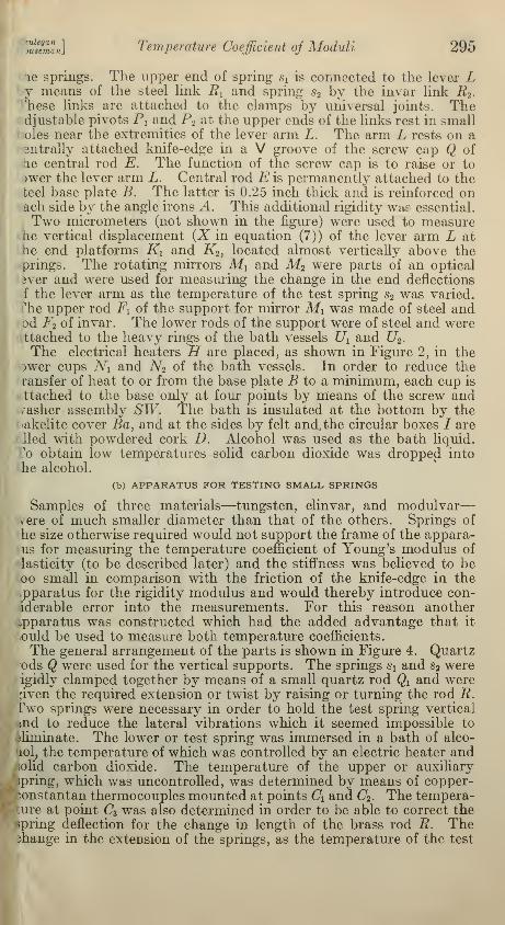
(b) APPARATUS FOR TESTING SMALL SPRINGS
Samples of three materials—tungsten, elinvar, and modulvar
—
vrere of much smaller diameter than that of the others. Springs of
he size otherwise required would not support the frame of the appara-us for measuring the temperature coefficient of Young's modulus of
lasticity (to be described later) and the stiffness was believed to beoo small in comparison with the friction of the knife-edge in thepparatus for the rigidity modulus and would thereby introduce con-iderable error into the measurements. For this reason another./pparatus was constructed which had the added advantage that it
ould be used to measure both temperature coefficients.
The general arrangement of the parts is shown in Figure 4. Quartzods Q were used for the vertical supports. The springs s x and s2 wereigidly clamped together by means of a small quartz rod Qx and were,'iven the required extension or twist by raising or turning the rod R.Two springs were necessary in order to hold the test spring vertical
md to reduce the lateral vibrations which it seemed impossible to
eliminate. The lower or test spring was immersed in a bath of alco-
10I, the temperature of which was controlled by an electric heater andlolid carbon dioxide. The temperature of the upper or auxiliary
spring, which was uncontrolled, was determined by means of copper-•>onstantan thermocouples mounted at points d and C2 . The tempera-ture at point <73 was also determined in order to be able to correct thespring deflection for the change in length of the brass rod R. Themange in the extension of the springs, as the temperature of the test

296 Bureau of Standards Journal of Research [Vol. 10
spring was varied, was measured by means of the optical systemshown in Figure 4. The mirror M was pivoted, a deflection of thespring causing the mirror to rotate. The connecting wire T was of
tungsten which was used because of its small temperature coefficient
of expansion. A small counterweight W kept the wire under a
*-©,
Figure 4.
—
Simplified diagram of the appara-tus used for the determination of the tempera-ture coefficient of the elastic moduli of materi-als of which only fine wire was available
constant tension. The method of computing the temperature co»
efficients is essentially the same as that for springs of larger wires.
In determining the temperature coefficient of Young's modulusmirrors Mi mounted on the quartz rod Qi were used to measure botl
the initial angular deflection and the change in angular deflection a?
the temperature was varied.

Keulegan]
Houseman\ Temperature Coefficient of Moduli
3. MATERIALS
(a) CHEMICAL COMPOSITION
297
The chemical composition of each of the materials is given in Table1. The analyses were made by the chemistry division.
Table 1.—Chemical composition of the materials
(a) NONFERROUS
ae
Material
Elements (in per cent)
o.02
Cu Zn Al Pb Sn Ni Si Fe P Mn
n~d.~n.d.1.11.03
1.03i .03i.03
1.03
1.03.61
Mg
6.16"
Be
314
15in
Phosphor bronze..dodo
Monel metalNickel silver
dodododo
doDuraluminBrass _..___.
95.394.695.033.261.7
62.264.464.860.4
64.54.473.098.1
n. d.
n.d.n.d.
n.d.n.d.n.d.
4.35.14.6
n.d.10.01n.d.63.810.5
14.219.39.815.3
18.4
n.'d."
"6."03"
"~."27~
n.d.n.d.n.d.1.7i.05
i.G51.051.051.05
1.C5.58
1.05
0.4.29.29
....
16
17
27.4
23.516.225.424.2
17.0
*26~9§"2~93~G3~
n.d.
n.d.n.d.n.d.n.d.
n.d.n.d.10.02
.03
n.d.n.d.n.d.n.d.
n.d.
....
18
1920
?1
?,7 0.513034 Beryllium bronze
.
1 9
(b) FERROUS
Spec-Material
Elements (in per cent)
No. C Mn P S Cr Si V Nl W Fe
1 Chromium vanadium steel 0.53.94.86.66.67
.13
.18
.83
.89
.14
.05
.08
.06
.08
.58
.84
.16
0.54.34.34.80.78
.48
.48
.64
.36
0.014.023.025.009.016
.018
.010
.030
.01
0.025.018.019.040.034
.019
.016
.024
.02
0.98 0.28 0.24411 .-..do- .195
12 do .13
8 4.973.509
613 do
Stainless steel (KA2) 17.417.517.617.3
11.6
.16
22 8.638.97.13.18
.65
23 do24 Stainless steel (Enduro A)
Stainless steel (Enduro AA)
Stainless steel No. 12 .
25
2629 1.13
1.5.18
1.88.14
.1431 Elinvar . 11.1
.1232.734.9
3.9n.d.
M9.832 Modulvar — ... »64. 5
1 Less than. 2 By difference. n. d. = not detected.
(b) FORM AND DIMENSIONS OF SPRINGS
The materials were obtained in the form of wires about 3 mm(0.125 inch) in diameter with the exception of those of elinvar, modul-var, and tungsten which were about 1.6 mm (0.06 inch) in diameter.The helical springs wound from the larger wires had the foliowhigapproximate dimensions: Diameter of the coils, 3.7 cm (1.5 inches),
length of unstressed spring 9 cm (3.6 inches) and number of coils,
11. The dimensions of those made from the smaller wires were:

298 Bureau of Standards Journal oj Research [Vol. 10
Diameter of the coils, 2 cm (0.8 inch); length of unstressed springs;
9 cm (3.6 inches); and number of coils, 16.
(c) HEAT TREATMENT AND HARDNESS
The heat treatment and the Vicker's hardness number of the springsafter winding are given in Table 2. The heat treatments were in
most cases made by the metallurgical division.
Table 2.
—
Heat treatment and hardness number of springs
SpringNo.
6b
8b9a9b10a10b
11a12a13a
13b
14a
15a16a17a18a18b
21a22a22b
23a23b24a24b
26a25b26a26b
27a29a
29b
31a32a33a34a
Spec-imenNo.
Material
Chromium vanadium steel.
.—do..Phosphor bronzePiano wire, No. 1— .do
Oil tempered wire, No. 1.
do
High-carbon steel.
do
Nickel steel.
....do
.—do—doMonel metal.
do
Piano wire, No. 2
Oil-tempered wire, No. 2.
High-carbon steel
.do.
Phosphor bronze.
doNickel silver.
dododo
Stainless steel (KA2).do
Stainless steel (Enduro A.)
.
do .--
Stainless steel (Enduro A. A).— .doStainless steel No. 12
—.do. —DuraluminSilico-manganese steel.
....do.
Brass..
Elinvar...ModulvarTungstenBeryllium bronze.
Vicker's
hardnessNo.
534210261
521
476
226
695
179
454167502261150
490511211
708
210
248250240212
272233488195
462176306168
273184328190
120281
418
238
Heat treatment
N, 900° C, air cooled; OQ, 850° C; T, 370° C.N, 900° C., air cooled; A, 850° C.Held at 100° C. for one and one-half hours.Held at 100° C. for one hour.N, 800° C. one-half hour, air cooled; A, 790° C. onehour, furnace cooled.
Held at 100° C. for one hour.N, 815° C. one-half hour, air cooled; A, 790° C. onehour, furnace cooled.
N, 790° C. 15 minutes, air cooled; A, 790° C, cooledin furnace.
N, 790° C. 15 minutes, air cooled; OQ, 790° C; T,260° C. one hour, cooled in air.
A, 815° C. one hour, cooled in furnace.
815° C. one-half hour, quenched in water.A, 760° C. one hour, cooled in furnace.760° C. one-half hour, quenched in water.Tested as received (hard drawn).A, in charcoal at 760° C. one hour, cooled in furnace.
Tested as received.Do.
N, 790° C. 15 minutes, air cooled; A, 790° C. 30 min-utes.
N, 790° C. 15 minutes, air cooled; OQ, 790° C; T,260° C. one hour.
Held at 100° O. for 24 hours.
Do.Do.Do.Do.
A, 800° C. two hours, furnace cooled.
Held at 100° C. for 24 hours.Do.Do.
Tested as received (hard drawn).Tested as received (annealed)
.
Tested as received (hard drawn).Tested as received (annealed).Tested as received (hard drawn).Tested as received (annealed).
Tested as received (hard drawn).Tested as received (annealed).Tested as received (hard drawn).Tested as received (annealed).
Tested as received (age hardened).A, 870° C. one hour, furnace cooled; N, 855° C. one-
half hour, air cooled.A, 870° C. one hour, furnace cooled; N, 855° C. one-
half hour; T, 510° O. 40 minutes, cooled in air.
Tested as received (hard drawn).
Tested as received.Do.Do.
Hard drawn; ago hardened 228° C. 3 hours, air cooled.
A= annealed. N= normalized. OQ = oil quenched. T= tempered.

HotZU Temperature Coefficient of Moduli 299
In the cases where the spring is listed as having been " tested as re-
ceived," the springs were coiled at room temperature from the wire as
received and were subjected to no heat treatment. No detailed infor-
mation is available relative to the heat treatment or cold work of thewires other than that given in the table. A number of the springs weresubjected to a temperature of 100° C. to relieve trapped stresses pro-duced in winding the spring. In every case the heat treatment refers
to that given the coiled springs.
In general, it was planned to make tests on the springs when the ma-terial was in the most favorable condition as to heat treatment or coldwork from the viewpoint of its use as an elastic element. In most cases
data were also obtained on the spring in the annealed condition.
4. EXPERIMENTAL PROCEDURE AND RESULTS
(a) EXPERIMENTAL PROCEDURE
For the purpose of determining the extensions Xi and X2 of the in-
stalled springs an auxiliary knife-edge balance was used to supportlever L (fig. 2) at its center. The cap ordinarily supporting the lever
L was lowered and then the deflections of the platforms Kx and K2 , for
various weights on the auxiliary balance, were measured by means of
micrometers. These readings were plotted against the loads on theauxiliary balance and the resulting curve for each spring was extra-
polated in order to determine the reading at zero load. The latter
reading was determined in this manner before and after each experi-
ment while the springs were at room temperature.Before subjecting the springs to the temperature cycle, the auxiliary
balance was disengaged and the springs were extended a desired amountby raising the screw cap on the center rod L. The readings of the mi-crometers in contact with K\ and K2 for this position of the lever armand those for the zero position as above determined sufficed to give
the initial extensions Xx and X2 of the auxiliary and test springs,
respectively.
To guard against errors arising from elastic after working, the drift,
or the change with time of the deflection of the springs at room tem-perature, was observed with the optical lever system. In most cases
the springs tested showed very small or no relative drift, but when the
relative drift was initially large, sufficient time was allowed for the rate
to decrease to a small value.
The change in the deflections of the two springs during the tempera-ture cycle was obtained by means of the two optical levers. In this
cycle the auxiliary spring],was|maintained at +30° C. while the tem-perature of the test spring was changed from +50° to —50° C. andback to +50° C. The temperature during a measurement was heldconstant within 0.5° C. The temperature of the auxiliary spring wasdetermined by means of a mercurial thermometer, the bulb of whichwas in the bath near the midportion of the spring. The temperatureof the test spring was determined by means of two calibrated liquid-in-
glass thermometers with the bulbs placed in the bath at points near the
upper and lower ends of the spring. The average of the readings ob-tained before and after every observation on the change of deflection
of the springs was taken as the temperature of the test spring. Thetemperature of one test spring was also determined during a tempera-ture cycle by means of two thermocouples which were soldered to the

300 Bureau of Standards Journal of Research [Vol. 10
spring, one at the top and the other at the bottom. The results by thetwo methods agreed within 0.5° C. throughout the range from + 50°
to -50° C.
TEMPERATURE, °C
Figure 5.
—
Change in deflection of spring No. 23a withchange in temperature
The optical lever above the test spring gave the data shown in curvesB, B', and B" and the optical lever above the auxiliary spring that incurves A, A', and A" with the sign of the ordinate reversed.
(b) CORRECTIONS APPLIED TO THE READINGS
During the temperature cycle to which the test spring was sub-jected, which was almost invariable from +50° to —50° C. and thenback to +50° C., the temperature of other parts of the apparatusalso changed with consequent changes in dimensions which in somecases contributed to the observed deflections. The source and amount

Keulegan 1
Houseman] Temperature Coefficient of Moduli 301
of these extraneous deflections were determined with considerablecare and their effect eliminated from the results. These parts were(a) the central invar rod and the caps (E and Q, fig. 2), and (6)
the system of rods which support the mirror M2 .
(c) METHOD OF REDUCING THE DATA
The method of reducing the data was essentially the same in all
cases and is most conveniently presented by giving the details ofthe reduction for a typical case. The data obtained experimentallyon spring No. 23a (stainless steel KA2) are shown graphically in
Figure 5. The ordinates represent the change x in the initial deflection
and the abscissas the corresponding temperatures of the test spring.
The deflections for temperatures decreasing are represented by opencircles and those for temperatures increasing, by filled circles. Thedeflections obtained by means of the optical mirror above the auxiliary
spring for mean initial deflections of the springs of 11.17, 7.80, and 3.95mm are given, with signs reversed, in the curves marked A, A f
, An',
respectively, and those obtained above the test spring, corrected for
the thermal expansion of the supports of the optical lever, are givenby curves B, B'', and B"
.
For most materials the points for increasing and decreasing temper-ature fell on the same curve within very close limits, but for spring
No. 23a (fig. 5) two distinct curves were obtained. In all cases like
the latter, the points midway between the two curves were used to
dxevaluate the slope -^ (equation (7)). The medians of the curves in
Figure 5 may be regarded, within the errors of observations, as arcs
of circles. Hence if we draw two straight lines, one joining the twopoints of the arc corresponding to +50° and 0° C, and the otherjoining the points corresponding to 0° and —50° C, the slopes of
dxthese two lines will give the value of -^ at the temperatures +25°
and —25° C. On this basis the following values were derived fromFigure 5.
Rate of change of deflection -^
0=25° C.
x Curves A Curves B Average
mm3.957.8011.17
mm/°C.0. 00157
. 00226
.00293
mm\°C.0. 00143.00217.00282
mm/°C.0. 00150.00221.00288
0=-25° C.
3.957.8011.17
0.00118. 00180.00227
0. 00130.00177.00228
0. 00124.00178.00228
These average values of -rRat +25° and 25° C. are plotted in
Figure 6 against X, the mean initial deflection of the springs. Thepoints fall on straight lines within the error of the experiments. Eachline in the figure is made to pass through a point, the coordinates of

302 Bureau of Standards Journal of Research [Vol.10
dxwhich are the mean values of X and of -tv and is drawn so that it
appears to the eye to have the least deviation from the experimentalpoints. The intersection of these lines with the axis of the ordinates
oo
Q_
i
Q25
tCO•z.
Q20
5 0115
Uo< QIOx:o
ou
v Irt"*x jg
0« ' + 25CC/*
/6--2! i°C
Q05
0.00
2 4 6 8 10 12
MEAN INITIAL DEFLECTION, X-MM.dx
Figure 6.
—
Relation of the rate of change in the extension, -?-> of the
spring No. 23a with temperature to the mean initial extension X ofthe springs
dxgives the values of —£> one of the quantities in the working formula,
equation (7). The following quantities were obtained from Figure 6.
Tem-pera-ture
X=10mmdx
dd
X=0dxo
de
2 (dx dx \X\dd dd)X10» per °C.
°C.+25-25
mm/°C.0.00205.00211
mml°C.0.00073
. 0000838.4
28. 8

HoUJsZan] Temperature Coefficient of Moduli 303
The thermal coefficient of expansion a of this alloy is stated to be1.6 X 10~ 5
. Hence, using the working formula (7), the temperaturecoefficient m is found to be
ra25 =-40.0X10- 5 per °C.
m.25 = -30.2 X10- 5 per °C.
The average of the above values is — 35.1X10⁻⁵ which is m , the
coefficient at 0° C. The ratio of two coefficients m25/m_ 2 ^ is 1.32.
(d) EXTENSION AT ZERO TENSION
It was seen in Figure 6 that the straight lines through the observedpoints cut the axis of the ordinates at two points the mean ordinate
of which is +70X 10~5 mm per °C. This is the rate of deflection for
the case of initial zero tension.
If the change in deflection with temperature at initial zero tension is
due only to the expansion of the parts, it can be shown that
c + l
X°~l + S1/S2
where c is the sum of the expansions of the parts exterior to the test
spring (a2 and b 2 , fig. 1) and I that of the test spring. It follows that
dc dl
dx _ d6 dd . .
dd'l + SJS,{J)
The contraction c of the spring assembly extending from the baseplate to the lever arm L (fig. 2), but exclusive of that of the test spring,
was determined when the temperature of the bath was changed from+ 50° to — 50° C. To determine this the test spring was replaced bya rod of phosphor bronze for which the thermal coefficient of expan-sion was known. While the temperature of the auxiliary spring wasmaintained constant, the change in its deflection was observed at anumber of temperatures of the phosphor bronze rod in the range from+ 50° to —50° C. From these deflections, together with the knowncontraction of the phosphor bronze rod and the previously deter-
mined contraction of the central rod, the contraction c was evaluatedand found to be linear with temperature. Four determinations gave
dc dca mean value for -^ of (56 ± 2)10~5 mm per °C. Tests showed that -r
ft
did not differ sufficiently from the above value in the two branches of
the temperature cycle to justify the use of separate values.
dxThe value of -i^» computed from equation 9 is +94X 10~5 mm per
°C. for the stainless steel spring for which data are given in Figures 5
dcand 6. The quantity -^ was computed on the basis of a thermal
coefficient of expansion of 1.6 X10"6 per °C. and a length of spring
156647—33 2

304 Bureau of Standards Journal of Research [Vol. 10
dcof 8.1 cm. The quantity j„ has the value given above and Si/S2 is
0.96. There is a difference of 24 X 10~5 mm per °C. between the above
computed value of -j~ and the average of the two values obtained
from Figure 6. Since experimental errors and the possibility that toohigh a value of the temperature coefficient of expansion was usedaccount only for a small part of the difference, this particular test
spring had a contraction during the temperature cycle other than thatwhich can be evaluated on the basis of pure thermal expansion.
A similar comparison of the two determinations of -rr- was made for
all of the other springs. For springs shaped from hard-drawn mate-rial the above discussed difference proved to be as large as 28 X 10"6
mm per °C. On the other hand, for springs which were annealed or
heat treated after being shaped from the material in the " as-re-
ceived" condition, the difference was smaller than 6 X 10"5 mm per °C.
(e) EXPERIMENTAL RESULTS
The values obtained for the temperature coefficient m of the
modulus of rigidity at 0° C. of the various springs tested are given in
Table 3. In addition, the heat treatment, the maximum shear
stress, the ratio —— and the value of the thermal coefficient of ex-m_25
pansion a used in evaluating m are given for each spring.
The temperature coefficient mQ is for all practical purposes the aver-
age coefficient for the temperature range —50° to +50°C. Ameasure of the variation of the coefficient with temperature is given
by the ratio ——
•
m_25
The values of the maximum shear stress given in Table 3 were com-puted from the formula
, 2LrJ a6
in which/ is the maximum stress to which the specimen was subjectedat its maximum extension, L is the force producing the maximumextension, and r and a are the radii of the coils and wire, respectively.
These stresses are all within the proportional limit.
(f ) ACCURACY OF RESULTS
The sources of experimental error are as follows:
1 . Uncertainty in the amount of the initial deflection of the springs,
and therefore in the quantity X. A comparison of the values of the
deflections obtained before and after the temperature cycle shows that
the difference was in no case more than 2 per cent, and in most cases

Keulegan]
Houseman] Temperature Coefficient of Moduli 305
Table 3.— Temperature coefficients of the elastic moduli
(The temperature coefficients of the modulus of rigidity and modulus of elasticity are, respectively, mand e, the subscripts of which denote the temperatures in degrees centigrade at which the values weredetermined. The coefficients mo and co are also the average values in the temperature range —50° to+50° C.)
Materia
Chromium vanadium steel.
doNickel steel. 5 per cent Ni .
.
doNickel steel, 3^ per cent Ni
doStainless steel (KA2), 0.14
per cent Cdo
Stainless steel (KA2), 0.05
percent CStainless steel (Enduro A) _
.
Stainless steel (Enduro AA)do
Stainless No. 12
do
Silico-manganese steel. ..
High-carbon steel No. 10
.
doHigh-carbon steel
.—do- -Piano wire, No.....doPiano wire, No. 2
Oil tempered wire, No. 1
.
.do.Oil tempered wire, No. 2
Phosphor bronze
™"do—-—.—— -—
—
Nickel silver, 10 per cent Ni
.
Nickel silver, 14 per cent Ni
.
Nickel silver, 19 per cent Ni
.
Nickel silver, 10 per cent Ni
.
Nickel silver, 15 per cent Ni
.
Nickel silver, 18 per cent Ni
.
Nickel silver, 19 percent Ni.DuraluminMonel metal
do
Heattreat-
ment
Brass, 73.0 per cent CuElinvarModulvarTungstenBeryllium bronze, 1.9 percent Be
H. r>.
A
H. O.H. D.
AH. D.A
H. D.A
ATATA
TRARR
AR
H. D.H. D.H. D.
H. D.H. D.H. D.H. D.H. D.
H. D.A
A. H.H. D.A
H. D.H. D.H. D.R
A. H.
Coef-ficient
ofthermalexpan-sionaXlOJ
1.171.171.051.061.04
1.04
1.641.6
W
1.041.04
1.11.1
1.11.1
1.1
1.11.1
1.11.1
1.1
1.11.1
1.71.71.7
1.81.81.81.81.8
1.81.82.31.31.3
1.8.6.0.4
moX 105
-26.2
-25.5-27.5
-27.3-27.1
-26.2
-43.6-39.9
-35.4-27.2
-25.5-26.7-25.7-28.3-25. 5
-22.8-23.0-22.5-27.1-21.8
-27.3-25.9-20.1-26.0-27.1
-24.3-27.8-41.1-38. 5-40.0
-37.1-37.8-37.7-39.1-38.8
-37.3-34.4-55. 1
-32.2-30.0
-38.8-7.2
-6.6
-33.4
my,
W-25
1.121.191.161.161.14
1.12
1.251.31
1.351.23
1.131.241.121.121.09
1.091.211.191.121.12
1.091.111.101.091.11
1.201.191.021.021.02
1.021.021.021.021.02
1.021.021.021.101.09
1.02
1.02
Maxi-mumshearstress
Lbs/in.*
9, 5009.2008,8008,8007,500
7,000
9,4006,800
9,4009,600
8,6008,8009,5007,9009,200
7,7007.9008.2007,0009,100
4,10010, 5008,500
10, 70010, 900
9,2009,6004,4005,4004,400
4,8005,5006,4005,3005,900
8,2004,5003.4006,3008.000
4,1006,500
33,100
4,800
eoXlO*
-26. 3
-25. 5-28.4-26.0-27.0
-27.1
-43.2-39.7
-37.9-26.6
-28.6-25.9-27.3-25.6-27.0
-24. 5
-25.1-20.1-26.0-19.3
-26.2-27.1-20.7-26.7-25.9
-24.0-25.4-38.0-40.0-36.0
-34.6-34.7-34.8-37. 9-34.5
-35.2-33.0-58.3-29.7-29.5
-38.9-6.6+48.2-9.5
-35.0
C25
C-25
1.131.071.061.101.08
1.09
1.131.16
1.191.10
1.061.041.151.121.13
1.121.141.121.071.12
1.111.061.141.101.10
1.091.051.021.061.05
1.061.031.061.031.07
1.051.051.121.021.12
1.17
(mo-e )X105
-0.1
1.3
.1
-2.5
-3.1
.8-1.6
2.7-1.5
-1.7
-2.1
2.41.1
2.5
1.1-1.3-.6-.71.2
.32.43.1-1.5
4.0
2.53.12.91.24.3
2.11.4
-3.2
2.5.5
-2.9
-1.6
T = Tempered.A = Annealed.
H. D. = Hard drawn.R = As received.
A. H. = Age hardened.

306 Bureau of Standards Journal of Research [Vol.10
less than 1 per cent. Errors of the same amount are thus introducedinto the value of the temperature coefficient m .
2. Uncertainty in the measured values of the temperature of thesprings. Tests showed the temperatures to be correct within 0.5° C.(See Sec. II, 4, on Experimental Procedure and Results, p. 299.)
3. The possibility that the contraction of a given test spring and its
supports during a temperature cycle depends upon the deflection ofthe spring as well as the temperature. If this contraction depends
-Z0 20
TEMPERATURE, *C
Figure 7.
—
Change in deflection of spring No. 6a withchange in temperature
The optical lever above the test spring gave the data shown in curves B,B', and B", and the optical lever above the auxiliary spring that inthe curves A, A', and A" with the sign of the ordinate reversed.
upon the deflection of the spring the error from its neglect in determin-ing the temperature coefficient will not be in excess of 2 per cent.
4. Possible error in the value of the coefficient of expansion of thesample materials. As this coefficient enters only as a second ordercorrection term (equation (7)) large percentage errors in the valueused will introduce only negligible errors in the final results.
Thus, any one determination of the temperature coefficient of
rigidity6m may be in error by an amount as large as 4 per cent.

Hoteman] Temperature Coefficient of Moduli 307
In the determination of the ratio —— the principal source of error
was that in some cases the changes in deflection x, were observed to bedifferent for decreasing and increasing temperatures. For examplein Figure 7, showing the data obtained on spring No. 6a, the points for
decreasing temperature as measured with the mirror above theauxiliary spring fall practically on a straight line, whereas the pointsfor increasing temperature fall on a curve. In this and similar casesthe mid line was used to represent the data. Although it is clear thatra obtained from the mid line is not open to an error large* than abovestated, the same can not be said for the determinations of the ratio
——• The error in cases where the ratio is approximately unity will
not exceed the 4 per cent above mentioned, otherwise it is likely to belarger, but is estimated not to exceed 10 per cent.
III. TEMPERATURE COEFFICIENT OF YOUNG'S MODULUSOF ELASTICITY
1. DERIVATION OF THE WORKING FORMULA
The apparatus used in the measurement of the temperature coeffi-
cient of Young's modulus of elasticity is shown in Figure 8. Only adescription sufficient to explain the derivation of the working formulawill be given here. The lower ends of the two springs $i and s2 , called,
respectively, the auxiliary and the test springs, are attached to theseparate bases, Bx (not shown in the figure) and B2 , which are heldfixed by suitable supports. Both of these springs are immersed in
liquid temperature control baths.
By a process analogous to that followed in the derivation of theworking formula for the temperature coefficient of the modulus of
rigidity, we find
S2' dd - $\de ddj UUj
where 3> is the mean of the absolute values of the initial twists of the
two springs, and <P are, respectively, the changes with temperature6 in the angular deflection of the test spring for an initial twist <j>2 andfor zero initial twist, and S2 is the stiffness of the spring with regardto angular deflection. The quantities <t>
and <j> are measured from the
position when the test spring is at +50° C. and the temperature of
the auxiliary spring held constant, and taken as positive when the
curvature of the coils of the test spring increases. The quantity <£> is
positive when the initial twist of the test spring is such as to increase
the curvature of its coils.
In terms of the constants of a helical spring the angular stiffness
ST is
o, WE
where E is the Young's modulus of elasticity, r is the radius of the
wire, and L is the length of the wire. This can also be representedfor a given spring by
Sf = pUE (11)

308 Bureau of Standards Journal of Research [Vol. 10
>XSS^SSSSSSSSVXV sn-
E^^vv>^n : ^x\sv^
Figure 8.
—
Cross-sectional diagram of the apparatus for the determination
of the temperature coefficient of Young's modulus of elasticity
(See the text for.the meaning of the letters.)

fifi£SS$\ Temperature Coefficient of Moduli 309
where is a numerical constant and L has the dimensions of length.is unaffected by the temperature if the ratio of r to L is invariant
with temperature. Differentiating equation (11) with respect to 0,
and then dividing by equation (11) we obtain
1 dS'_l dE,.
S'W~E"30 +3a (12 )
where a is the temperature coefficient of linear expansion. Aftermaking the obvious substitution in equation (10) there results
Let
1 dE 2/d4> d<j> \
E~^-~Ad~e~~dd)~ ZcL (13)
«4f wEquation (13) is the working formula for the experiments. Thequantity e is defined as the temperature coefficient of Young's modulus
of elasticity. The quantities -£ and -^ are the rates of change ofad ad
the angular deflection of the test spring corresponding, respectively, to
the mean of the absolute values and to the zero value of the initial
deflections $ x and 3>2 of the springs.
2. DESCRIPTION OF THE APPARATUS
Figures 8 and 9 show a cross-sectional diagram and a photographof the apparatus for measuring the temperature coefficient of Young'smodulus. In Figure 8 the complete assembly is shown only for theupper spring. The construction of the lower spring assembly is thesame as that of the upper. The base plates (B2 , fig. 8), which holdfirmly the circular cups (N2 ), are bolted to two vertical rigid rods.
Only one of the rods, Ri is shown in the diagram, but both may beseen in Figure 9. The construction of the baths TJ\ and U2 andthe lower connections of the springs Si and s2 is similar to that in the
apparatus for determining the temperature coefficient of the rigidity
modulus of springs of heavy wire. Special clamps d and C2 termi-
nating in circular disks A and D2 with central projections Pt and P2
are attached to the upper connections of the springs. The midpor-tions of the clamps, Ix and I2 are square in cross section and one, I2 ,
is made of glass in order to obtain better temperature insulation.
The springs after being given the initial deflection, are interconnected
by frame F which is sufficiently strong so as not to suffer appreciable
distortion. Each of the disks A and D2 has 18 perforations cir-
cularly distributed near the edge, to facilitate the clamping to the
frame F.An optical system consisting of the mirrors M2 and M2 , telescopes
and scales, was used for measuring the angular deflection of eachspring. There were two mirrors at both Mi and M2 , inclined 90°
to each other. The scales were placed at such distances from eachmirror so that a rotation of one degree of arc gave a change in reading
of 2 cm on the scale. Readings on the scale were estimated easily
to tenths of a millimeter.

310 Bureau of Standards Journal oj Research [Vol. 10
3. MATERIALS
The same springs were used to determine the temperature coef-
ficients of both of the elastic moduli. These are described, togetherwith the chemical composition and heat treatment, in the section onthe temperature coefficient of the modulus of rigidity.
4. EXPERIMENTAL PROCEDURE AND RESULTS
(a) EXPERIMENTAL PROCEDURE
The test procedure was very similar to that followed in the exper-iments for determining the temperature coefficient of the rigidity
modulus includmg the method of measuring and controlling the tem-perature of the springs. Similarly, the temperature of the auxiliary
spring was maintained constant at +30° C. and that of the test
spring varied in a cycle from +50° to —50° C. and back to +50° C.At various points in the cycle the change in deflection of both springs
was measured by means of the optical system.
(b) METHOD OF REDUCING THE DATA
The method followed in reducing the experimental data will bepresented by giving an example, using the data for high carbon steel
spring No. 9b, given in Figure 10. Here the ordinates represent
twice the change<f>
in the initial deflection <i> and the abscissas the
temperature of the test spring. The open circles represent deflections
observed at decreasing temperatures of the test spring and the filled
circles, deflections at increasing temperatures. The mean initial
deflections of the test spring, measured at room temperature, about25° C, were 92.0°, 12.5°, -8.1°, and -87.5°.
The lines through the observed points are not straight and may beregarded as arcs of circle. Hence, if the slopes of the two straight
lines, one joining points on the arc at 0° and 50° C, and the otherjoining the points at 0° and —50° C, are determined, we obtain,
respectively, the quantity —£ at the temperatures 25° and —25° C.
The results of such determinations for the curves in Figure 10 are:
Initial
deflectionld6
J*lde
Degrees92.012.5-8.1-87.5
Degrees per ° C.6=26° c.
0.0242.0036
-. 0025-.0225
Degrees per ° C.6= -26° C.
0. 0215.0024
-.0020-.0200
These values of 2 -? for 25° and —25° C. are plotted against <t> in
in Figure 11. The points for each temperature lie on a straight line
within experimental errors. Each line is made to pass through a
point whose coordinates are the means of coordinates of the plotted
points and is so drawn that its deviation from these points appears byeye to be a minimum. The intersection of these lines with the axis

B. S Journal of Research, RP53I
Figure 9.
—
Apparatus for the determina-
tion of the temperature coefficient of
Young's modulus of elasticity

Keulegan 1
Houseman} Temperature Coefficient of Moduli 311
of the ordinates gives the value of 2 ~ The following quantities
are read from the graph
:
COuUJ
ouQ
I
Temper-ature
4>d<t>
zde * l
de
° C.
+25-25
Degrees100100
Degrees per° C.0. 0260.0230
DegreesDegrees per
° C.
-05
-L0
-15
-2L0
-2.5
H -05
05
o
2.0
1.5
1.0
0.5
!
**-32DE&
.
i- 12-5 EG.
o- i> -8.1 DE6
5- -87.5 DE&
"<.
I >>cj-(>0 -40 -20
TEMPERATURE,
20 40
Figure 10.
—
Effect of change in temperature of test springon the angular deformation 3> of spring No. 9b
The thermal coefficient of expansion a of this material is 1.1 X 10~5.
Inserting the above values into the working formula, equation (13)
gives -29.3X10"5 at +25° C. and -26.3XKT6 at -25° C. for the
temperature coefficient e of Young's modulus of elasticity. Thevalue at 0° C. is the average of these values or e = — 27.8 X 10~ G per° C. The ratio of the values at +25° and -25° C. is
e25 = 1.13

312 Bureau of Standards Journal of Research [Vol. 10
The mean value <£ of the absolute values of the initial angulardeflections of the two springs at 25° C. is used in evaluating e_25 ande25 without the introduction of sensible error.
(c) EFFECT OF TEMPERATURE AT INITIAL ZERO ANGULAR DEFLECTION
The rate of change of angular deflection is plotted in Figure 12
against the mean initial angular deflection for springs of oil-temperedsteel (No. 5a). The straight line A represents the results ofJ;he tests
on this spring when prepared|from the original temperedfmaterialwithout subsequent heat ^treatments. :It meets the axis of the ordi-
nates at a point other than the origin, which means that this springdeflects with change in temperature when the initial angular deflection
0.03
0.02
0.01
d *Ido
° -0.01
y
5 -o.oa
•0.03
><y.
e—25%^^^^y£«*z fc
H00 -50 HO -40 -20 20 40 60 80
MEAN INITIAL ANGULAR DEFLECTION, i - DEGREES
100
Figure 11.
—
Relation of twice the rate of change in angular deflectiondd
temperature to the mean initial angular deflection <£ of spring No. 9b
with
is zero. Let -P- be the rate of change with temperature of the deflec-
tion of the test spring when the spring is unstressed and entirely free
of the clamp C. Assuming -~ to be independent of the deflection $
it can be shown thatdipp
de) ^- Calculated by meansde
of this formula, in which Si'/S2 ' is assumed to be unity and -^ is
obtained from the graph, the rate of change of twist -j^° is 0.020 degree
per °C.To show that this rate of change of deflection at zero angular de-
flection actually occurs the test spring^vas disengaged from the clampand its deflection measured as the temperature was varied.

Keulegan 1
Houseman. Temperature Coefficient of Moduli 313
The following results were obtained, which are in satisfactoryagreement with value given above.
Tempera- Degree of
ture of the twist perspring °C.
°C.+15 0.022+8 .022-16 .021-24 .021
0.05
oo
U0- 0.04
u1 0.03
zo0.02
0.01
5
-0.01
y/k
<
/«, //
° -0.02UJ
cr:
-100 -50 50 100
MEAN INITIAL ANGULAR DEFLECTION, §-DEGFigure 12.-
—
Relation of twice the rate of change in9 rleh
angular deflection -ttt with temperature to the mean
initial angular deflection 3> of the springs No. 5aand 5b
Data represented by the line A were obtained with the springsshaped from the oil-tempered wire. The test spring shows twist
at zero deformation. Data represented by the line B were obtainedwith the springs annealed after shaping
To show that -¥§ is substantially constant for all values of thedu
deflection of the spring the following experiment was performed. Theauxiliary and test springs were initially twisted in opposite directions
by amounts $1 = —83° and $2= + 83° and clamped. The tempera-

314 Bureau oj Standards Journal of Research [Vol. w
tures of both of the springs were varied as a unit starting from a com-mon temperature. There was a consequent twist of 0.020° per °C.which is in good agreement with the results previously obtained.The deflection with temperature at the initial zero angular deflec-
tion is relatively large for steel springs which were not heat treatedafter being wound.For springs heat treated after winding this effect was practically
zero which is shown in a striking way by curve B in Figure 12 whichrepresents the data obtained after annealing spring No. 5a. The
fact that -^° is here practically zero suggests that this deflection with
temperature results from the stressed condition of the spring material.
Probably it is due not so much to a modification during a temperaturecycle of the internal stresses introduced by working the material, as
to the fact that the material has additional changes in deflection in
the internally stressed portions due to the effect of temperature onthe modulus.
Springs shaped from nonferrous hard-drawn materials show asimilar effect but smaller in magnitude.
(d) EXPERIMENTAL RESULTS
The values of the temperature coefficient e of Young's modulus of
elasticity at 0° C. are given in Table 3. Values of the ratio e25/e_25
of the temperature coefficients at +25° and —25° C. and the differ-
ence m — e between the temperature coefficients of the two moduliare also given.
The temperature coefficient e is also the average value of the coeffi-
cient in the temperature range —50° to +50° C. The ratio e25/e_25
is a measure of the variation of the coefficient with temperature.No values of the temperature coefficient were derived from the
data obtained on stainless steel spring No. 23b, since, due to the anom-alous behavior which is discussed later, these would be of little signif-
icance.
The temperature coefficient e was not obtained for modulvar owingto the excessive vibration of the small spring which had to be used.
The maximum bending stresses at the maximum twist of the springs
were in all cases considerably less than those in shear. Consequently,the stresses were in all cases below those at the elastic limit.
(e) ACCURACY OF RESULTS
t
The sources of error in the determination of the temperature coeffi-
cient of Young's modulus are (1) in the measurement of the meaninitial deflection of the auxiliary and test springs and (2) in the
measurement of temperature of the springs. For the great majorityof the springs the error in determining the initial deflection was within
1 per cent and in all cases the error in the temperature was within1° C. Thus, not considering the possible error in the value of the
thermal coefficient of expansion, the error in the coefficient does notexceed 2 per cent.
The error in the ratio of the temperature coefficient at +25° C.
to that at —25° C. is principally due to the difference in the angulardeflection of the spring for decreasing and increasing temperatures.This difference in deflection was very much less than in the case of
the experiments to determine the temperature coefficient of the modu-lus of rigidity and therefore the errors are substantially less.

Hollemln] Temperature Coefficient of Moduli 315
IV. DISCUSSION1. ANOMALOUS BEHAVIOR OF STAINLESS STEEL
The behavior of annealed stainless steel (KA2) spring No. 23bcontaining 0.05 per cent carbon, is very unusual compared with those
TEMPERATURE, °C
Figure 13.
—
Effect of temperature on the angular deflection
of a spring (No. 23b) of annealed stainless steel
Each group of curves A, B, and C and E, F, and O are the results of thefirst, second, and fifth test for an initial angular deflection (*) of 41.6 forthe first group and 11.4° of arc for the second. Curves D were obtainedafter three temperature cycles for an initial angular deflection of 41.6°, andshows the spring to be in the cyclic state. The open circles represent ob-servations made in the decreasing temperature part and the solid circlesin the increasing temperature part of the cycle.
of other materials. The results of some of the tests are shown inFigure 13.
The change in angular deflection as a function of the temperatureis given in Figure 13. Before obtaining these data the springs weregiven an average angular deflection of 42° and the differential drift

316 Bureau of Standards Journal of Research [Vol 10
noted which after a period of time became less than 0.02° per hour.The test spring was then subjected to the usual temperature cycleand the change in deflection measured, obtaining the values shown in
curve A (fig. 13)._As the temperature was decreased from +50° C.
the modulus first increases and then decreases, while during the re-
turning half of the temperature cycle (—50° to +50° C.) the rate ofchange of the modulus was much more constant. At the end of this
temperature cycle the metal had a lower value of the modulus thanat the start. This difference in modulus became less and less for eachsucceeding temperature cycle, becoming zero after the fifth cycle.
As has been previously stated (equation (14) the temperature coef-
ficient at any temperature is in linear relation to the slope of this
curve from which it is evident by inspection that the coefficient of
Young's modulus departs considerably from a constant value.
Curve B of Figure 13 gives the data for the second temperaturecycle and curve C that for the fifth. Notice in the latter curve thatthe temperature coefficient varies with temperature and also that themodulus has different values at a given temperature, except at +50°and —50° C, in the two branches of the temperature cycle. Furthertests showed that this appears to be the cyclic state of the materialfor this temperature range and deflection. After making test No. 5,
curve C, the springs were allowed to untwist and then were againretwisted to the same angular deflection. It was now necessary to
pass the spring through three temperature cycles to establish againthe cyclic state (tests Nos. 6,7, and 8). In test No. 10 the temperaturecycle was from + 50° to + 5° and back to + 50° C, the data for whichare shown by curve DD' in Figure 13. This was repeated in test
No. 11. In test No. 12 the temperature cycles were from +50° to- 50° to + 10° to - 50° to + 50° C, data for which are shown by thecurves DD" D" ' D in Figure 13. This figure clearly shows that atrue cyclic state was established. Curves E, F, and G in Figure 13,
give the results of the first, second, and fifth tests when the initial
deflection was 11.4°.
The behavior of this material was similar in the experiments for
determining the coefficient of the rigidity modulus although a slightly
different procedure was followed in these experiments. In the first
temperature cycle a curve similar in form to that of curve A (fig. 13)
was obtained. After this test the spring was subjected to three suc-
cessive temperature cycles ( + 50° to —50° to +50° C.) in as short a
period of time as possible, without making measurements of the
deflection. During the next cycle measurements showed the spring
to be in the same cyclic state, as shown in curve C of Figure 13
which was obtained as a result of tests which took a definitely muchlonger time to make. Since the cyclic state was obtained independ-ently of time it is concluded that the behaviour is mainly an effect
due to change in the constitution with temperature and not of elastic
afterworking.The effect was obtained only to a slight degree with stainless steel
spring No. 24b which is in agreement with the negative result of cold
treatment obtained by Luerssen and Green 2 with a sample of ap-proximately the same composition, especially as to the carbon con-
tent. The difference in behavior of springs 23b and 24b appears to be
» Q. V. Luerssen and O. V. Green, Trans. Am. Soc. Steel Treat., vol. 19, p. 501, 1932.

miSn] Temperature Coefficient of Moduli 317
caused by the difference in the carbon content, respectively, 0.05 and0.14 per cent, which seems to be reasonable according to the work of
Krivobok and Gensamer. 3
2. RELATIVE VALUES OF THE TEMPERATURE COEFFICIENTS
An inspection of Table 3 shows that, of the pure metals, tungstenhas the smallest temperature coefficient and also the smallest coeffi-
cient of thermal expansion. This is in accordance with the modifica-tion of Wertheim's law given by Andrews, 4 which includes as a corol-
lary, that for pure metals, a small temperature coefficient of elasticity
and a small thermal coefficient of expansion are associated. Therelatively large differences in the coefficients m and e for tungstenmay be due to the fact that the crystal structure of the wires wasfibrous rather than isotropic.
With the exception of stainless steel KA2, elinvar, and modulvar,it is seen that the temperature coefficients of the steels vary within arather small range, from 19 to 27 X 10~5
.
Modulvar, which has practically the same composition as invar, is
known 5 to have a large positive coefficient which is confirmed by thepresent results. The values for the sample of elinvar were ratherhigher than expected. 5 However, the material is known to require
careful heat treatment to obtain the low coefficient. It was not heattreated after the cold work incidental in forming the spring.
The two stainless steels KA2, with carbon contents of 0.14 and 0.05per cent, have temperature coefficients of the elastic moduli whichare considerably higher than those of the other steels. These steels
also have higher thermal coefficients of expansion.Of the group of nonferrous materials, duralumin has the largest
temperature coefficient and Monel metal the smallest. The coefficients
of the nickel silvers, brass, phosphor bronze, and beryllium bronzediffer but littel from those found for copper by other investigators.
3. VARIATION OF THE TEMPERATURE COEFFICIENTS OF THE MODULIWITH TEMPERATURE
The coefficients m and e given in Table 3 are also with but negli-
gible error the average values of the coefficients for the temperature
interval —50° to +50° C. Although the values of the ratios —
—
m. 25
and —— are open to question in some cases, they are even in these£-25
cases of value as an indication of the variation of the temperaturecoefficients with temperature. Very roughly, but sufficiently accuratefor many purposes, the ratio
m m50 m25
m_ 50 m m_25
and similarly for the coefficients of Young's modulus.The coefficients in all cases increase in absolute value with increasing
temperature. For the materials, phosphor bronze, nickel silver, and
a V. N. Krivobok and M. Gensamer, Trans. Am. Inst. Min. and Metall. Eng., Iron and Steel Div., p.
325, 1931.' J. P. Andrews, Phil. Mag., series 6, vol. 50, p. 665, 1925.
» P. Chevenard, Travauz et Memoires de Bur. Int. des Poid et Mes., vol. 17, 1927.

318 Bureau of Standards Journal oj Research [Vol. 10
brass, all containing copper, the rate of increase is not as large as insteel, duralumin, and Monel metal. For some of the stainless steelsthe coefficients appear to increase at a greater rate than for othersteels.
For high-carbon steels (spring Nos. 6a, 6b, 13a, and 13b) the averagevalue
SSU.1.13 and -^U-1.11
Tomlinson's expression 6 for the relation between the rigidity modu-lus of iron and temperature for the temperature range 0° to 100° C.gives 1.11 for the above ratio of the torsion moduli when extrapolatedto —25° C. Dadourian's expression 7 for the relation of Young'smodulus of steel and temperature for temperatures above 0°C, gives1.29 for the ratio of the modulus at +25° C. to that at -25° C.
4. TEMPERATURE COEFFICIENT OF POISSON'S RATIO
Gruaeisen 8 in an important paper on the compressibility of isotropicelastic materials has deduced the relations
I. ra>e> 7
II. m-e= -^ (e ~y)
-r-r-r 1 da 1 + (7 , N
IIL ^ =~ (w -<°
where a is Poisson's ratio, ?? the compressibility and the thermal coeffi-
cient of compressibility. The first relation is based on the assumptionthat compressibility, as well as Poisson's ratio, increases with temper-ature. The second and third relations result from the isotropic
character of elastic materials.
GrtThe value of the quantity -5- is known to be a small fraction,
different for various materials, but always lying between the limits
one-sixth and one-twelfth. The above relations are very useful as
they afford us a means of knowing how large the difference betweenthe two temperature coefficients of the moduli can be.
When, with the first Griineisen relation in mind, the two coefficients
m and e are compared it is found that, except in a few cases, m — e
is positive, and also that the difference is larger for nonferrous materialthan for the steels.
Restricting our consideration to the steels, it may be inferred,
because of Grtineisen's second relation, that either the thermal coeffi-
cient of Poisson's ratio for steels at 0° C. is zero or a very small quan-tity. Bock's 9 results on the direct determination of Poisson's ratio
of hardened English steel by Kirchoff's method and for a temperature
• II. Tomlinson, Proc. Roy. Soc, vol. 40, p. 343, 1886.i H. M. Dadourian, Phil. Mag., vol. 42, p. 442, 1921.• E. Griineisen, Ann. d. Phys., vol. 33 (338), p. 1239, 1910.• A. Bock, Wied. Ann., vol. 52, p. 609, 1894.

Hmueman] Temperature Coefficient of Moduli 319
range, 20° to 150° C, may be represented by the following expres-sion
—
1,000a = 255.6 + 0.0190 + O.OOOO902
from which we find for the thermal coefficient of Poisson's ratio at0° C.
££-7x10-
Using Gruneisen's third relation this gives the value 2X 10" 5 for thedifference m — e which agrees with the results for high-carbon steels
given in Table 3.
Katzenelsohn, 10 Schaefer, 11 and Angenheister, 12 among the earlier
observers, have determined both of the quantities m and e fromexperiments made on the same specimen. Although they find mto be larger than e, Griineisen has remarked that with these observersthe difference m — e was too large to be compatible with his secondrelation, particularly for results on materials of high melting points.
Goens, 13 among recent observers, has determined these quantities for
aluminum and brass by a new method from the same specimen of eachmaterial. The difference m — e obtained by him for brass is of thesame order of magnitude as that in the present investigation.
5. EFFECT OF HEAT TREATMENT ON THE TEMPERATURE COEFFI-CIENTS OF THE ELASTIC MODULI
The coefficients of the elastic moduli of high-carbon steels (springs
6a, 6b, 13a, and 13b, Table 3) are affected very definitely by heattreatment. The coefficients of the annealed specimens are about 20per cent less than those for the tempered specimens. It is significant
that annealing brings the value of the coefficients very near to the
value found by other experimenters for iron. Coefficient e for iron wasfound by Geons 14 to be - 21.3 X 10" 5
; by Katzenelsohn15 -22.3 X10" 5;
by Thomas 16 -19.4X10" 5. For iron Tomlinson 17 found mG to be
-24.4 X 10"5; Guye and Fredericksz 18 -21.3 X 10"5
.
In alloys steels, however, the effect of heat treatment is not verydefinite; differences that were found were of the same order as the
errors of experimentation. The results for chromium-vanadium steel
do not contradict those of Brombacher and Melton 19; the results on
nickel steel agree with those of Kimball and Lovell.20
Among the nonferrous materials one spring of the nickel-silver
group was tested in the as-received condition and also after annealing.
Annealing produced, as is seen from the Table 3, a decrease of about10 per cent in the value of the coefficients, which is a decrease of the
same order as found by Brombacher and Melton. In the case of
Monel metal the decrease was less than that found for nickel silver.
i» N. Katzenelsohn, Inn. Diss. (Berlin), 1887." C. Schaeffer, Ann. d. Phys., vol. 5 (310), p. 220, 1901.» G. Angenheister, Ann. d. Phys., vol. 11 (316), p. 188, 1903." E. Goens, Ann. d. Phys., vol. 4 (396), p. 733, 1930.» See footnote 13, p. 319.:J See footnote 10, p. 319.i« Paul A. Thomas, Dissertation, (Jena) , 1899.17 See footnote 6, p. 318.» C. E. Guye and V. Fredericksz, Compt. Rend., vol. 149, p. 1066, lorw.19 See footnote 1, p. 290.«> A. L. Kimball, jr.. and D. E. Lovell, Phys. Rev., vol. 26, p. 121, 1925.
1-56547—33 3

320 Bureau of Standards Journal of Research [Vol. 10
V. CONCLUSIONS
The temperature coefficient of the modulus of rigidity and of themodulus of elasticity of a number of metals and alloys have beendetermined in the temperature range — 50° to f 50° C. The coeffi-
cients were obtained in so far as possible on each material in the con-dition of heat treatment or cold work most suitable for its use as aspring or diaphragm and also in the annealed condition. The ex-perimental results are presented in Table 3.
It is shown that Gruneisen's three relations between the tempera-ture coefficients and Poisson's ratio were in general confirmed bythese data.
The temperature coefficients were found, for the most part, to bedependent, to a significant extent, on the heat treatment and coldwork of the material.
Except for tungsten the percentage difference in the two tempera-ture coefficients was sufficiently small so that for practical purposesthey may be taken as equal.
The coefficients, in general, varied with temperature. The averagevalue for the temperature interval —50° to 50° C. is that for 0° C.given in Table 3.
The coefficients are independent of external stress within the maxi-mum stress at which the springs were tested.
VI. ACKNOWLEDGMENTS
The Aluminum Co. of America, the American Steel & Wire Co., theInternational Nickel Co., the Seymour Manufacturing Co., thePhosphor Bronze Smelting Co., the Beryllium Development Corpora-tion, the Wallace Barnes Co., and the Cuyahoga Steel & Wire Co.cooperated by furnishing special materials for use in this investigation.
We are greatly indebted to Dr. W. G. Brombacher for valuableassistance, especially in the preparation of the manuscript, and to
F. Cordero for his suggestions in the design of the apparatus.
Washington, September 10, 1932.