telescope project development seminar - university … · telescope project development seminar...
TRANSCRIPT

Visiting Professor Lecture
Telescope Project Development Seminar
Session 2: Site, Enclosure and Facilities
Matt Johns
1/20/2017
U. Tokyo
2/9/2017 1Telescope Project Development

Visiting Professor Lecture
Topics
• Site Selection
• Enclosures & Facilities
• Enclosure Thermal Engineering
• Magellan Enclosure Development
2/9/2017 2Telescope Project Development
Session 2 outline
Visiting Professor Lecture
Site Selection
2/9/2017 Telescope Project Development 3

Visiting Professor LectureWorld Sites (optical telescopes > 6m)
2/9/2017 4
1. Hawaii USKeck (10m)Gemini N (8m) Subaru (8m)TMT (30m)
2. San Pedro Martir, MexicoTSPM (6.5m)
3. Arizona, USAMMT (6.5m)LBT (2 x 8m)
4. Texas, USAHobby-Eberly (10m)
5. ChileGemini S (8m)VLT (4 x 8m)Magellan I & II (2 x 6.5m)LSST (8m)GMT (25m)EELT (39m)TAO (6.5m)
6. La Palma, Canary IslandsGTC (10m)
7. South AfricaSALT (10m)
Italic = under development
1
432
5
6
7
?
~
Telescope Project Development

Visiting Professor Lecture
• Site conditions strongly affect the design, construction and operation of an observatory including the science that can be done
• Site selection starts early in the telescope project development process
• Characterizing a site is a multi-year (>2) process, especially for an undeveloped site.
• Testing is required at each prospective site.
• Monitoring should cover all observing seasons
• Even a developed site may need additional testing to support new operating modes (e.g. adaptive optics)
• Securing the rights to a site and performing environmental impact studies can take years. Best start early to avoid surprises.
• Appoint a team to conduct the site evaluation and selection process
• Selection process requires approval from the top-management and the Board
• The procedure and criteria for selecting a site needs to be specified at the start to ensure the process is comprehensive and fair.
2/9/2017 5Telescope Project Development
Site Selection
Visiting Professor LectureSite Selection Factors
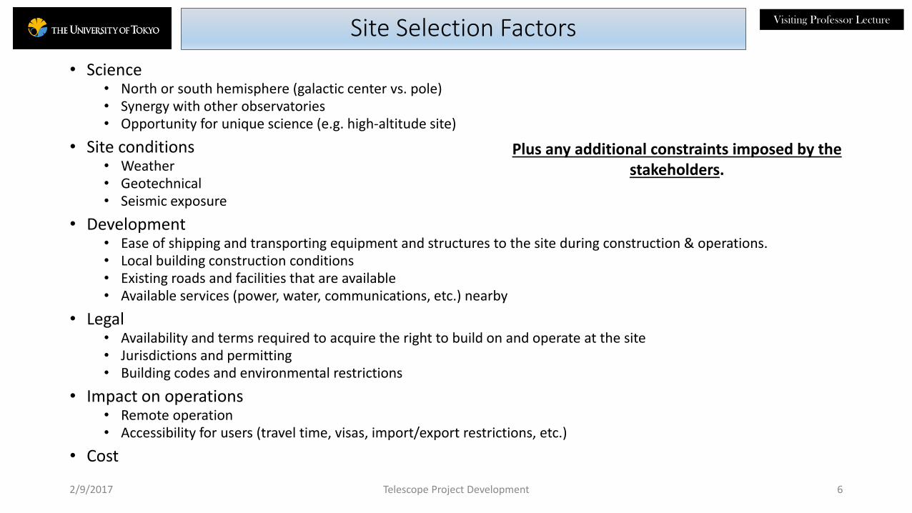
• Science• North or south hemisphere (galactic center vs. pole)• Synergy with other observatories • Opportunity for unique science (e.g. high-altitude site)
• Site conditions• Weather• Geotechnical• Seismic exposure
• Development• Ease of shipping and transporting equipment and structures to the site during construction & operations.• Local building construction conditions• Existing roads and facilities that are available• Available services (power, water, communications, etc.) nearby
• Legal• Availability and terms required to acquire the right to build on and operate at the site• Jurisdictions and permitting• Building codes and environmental restrictions
• Impact on operations• Remote operation• Accessibility for users (travel time, visas, import/export restrictions, etc.)
• Cost
2/9/2017 6
Plus any additional constraints imposed by the stakeholders.
Telescope Project Development

Visiting Professor LectureProcess
• Testing starts with gaining access to the site.
• Permission from owner or controlling institution
• Getting physical access to the site for installing equipment – roads, trails, etc.
• Sites at established observatories are obviously a lot easier to characterize and can provide a baseline of recorded conditions and support infrastructure.
• Site test team
• Assemble test equipment
• Install equipment on site
• Collect data over an extended period of time.
• Compile data into a report for comparison with other sites.
• Site selection review and ranking
• Negotiate lease or purchase for top ranked site
2/9/2017 7Telescope Project Development

Visiting Professor LectureEnvironmental Characterization
• On-site measurements
• Weather statistics (temperature, wind speed and direction, humidity)
• Transparency/cloud cover
• Precipitable water vapor (PWV)
• Light pollution
• Atmospheric parameters (“seeing”, Cn2(h), AO coherence time τ0, Na layer)
• Dust
• Environmental conditions are captured in a top-level document maintained under change control.
• Operational and Survival Conditions are specified.
2/9/2017 8Telescope Project Development

Visiting Professor LectureWeather Station
• Weather station mounted at the proposed telescope site
• Set height to sample the conditions above ground effects
• Recorded quantities
• Temperature
• Humidity
• Wind speed & direction
• Sample data fast enough to compute rates of change
• Store the readings in a data base for post processing statistics
• Tag data with observed sky conditions (e.g. “clear - suitable for astronomy”) when the data were taken.
2/9/2017 9
Davis weather station
Telescope Project Development

Visiting Professor LectureTemperature Statistics examples
2/9/2017 10
Median temperatures with 1 sigma barsfor four LCO sites
on clear nights over 3 years
Cumulative histogram of temperature gradientsfor four LCO sites
over 3 years
Telescope Project Development

Visiting Professor LectureWind Statistic examples - LCO
2/9/2017 11
Cumulative wind speed statistics for four LCO sites on clear nights over 3 years
Magellan
GMT
Telescope Project Development
Normalized Wind Direction Histogram

Visiting Professor LectureWind Statistic examples - TAO
2/9/2017 12Telescope Project Development
Diurnal wind speed histogram for the TAO site on Cerro Chajnantor.
Max. wind speed 68 m/s
TAO is located on the summit of Cerro Chajnantor in the Northern Chile Science preserve. It is another site like LCO with highly bi-directional wind direction. This makes optimizing the site and enclosure layout simpler.

Visiting Professor LectureTransparency/Cloud Cover
• Transparency and cloud cover can be monitored with an all sky camera similar to the ones deployed at Cerro Tololo and Las Campanas Observatory.
• The camera is mounted on a mast under a transparent dome and operates automatically to record sky conditions throughout the night.
• Data is processed and the results are archived in a database.
• If the proposed site is located at or near an existing observatory, the nightly telescope operator logs can be mined for this information.
2/9/2017 13
Tololo All-Sky Camera
Smith, R., Walker, D., and Schwarz, H., (2004)
Clear (%) Clear and Partly Clear (%)Spring 70 87Summer 79 92Fall 63 81Winter 51 67
Nightly Statistics for LCO
Telescope Project Development
Visiting Professor LectureSeeing measurements
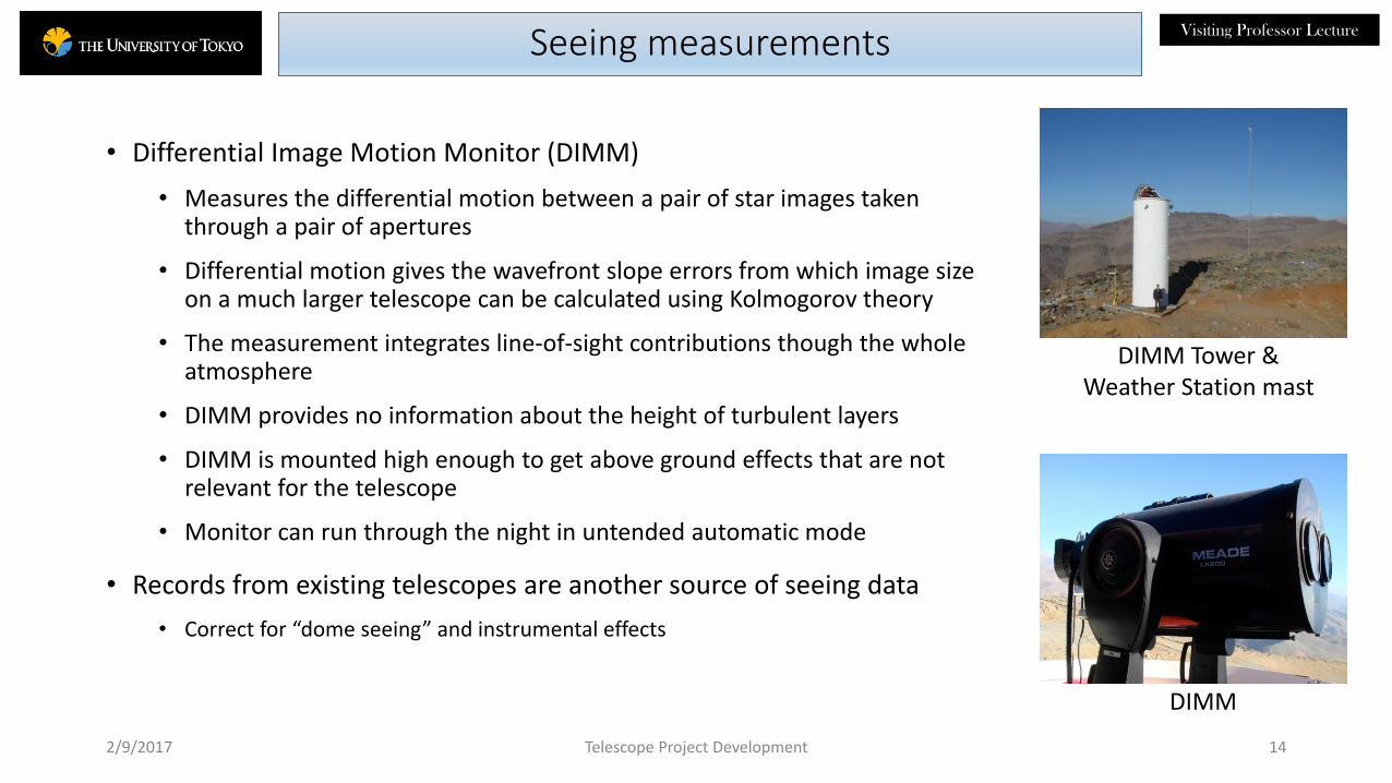
• Differential Image Motion Monitor (DIMM)
• Measures the differential motion between a pair of star images taken through a pair of apertures
• Differential motion gives the wavefront slope errors from which image size on a much larger telescope can be calculated using Kolmogorov theory
• The measurement integrates line-of-sight contributions though the whole atmosphere
• DIMM provides no information about the height of turbulent layers
• DIMM is mounted high enough to get above ground effects that are not relevant for the telescope
• Monitor can run through the night in untended automatic mode
• Records from existing telescopes are another source of seeing data
• Correct for “dome seeing” and instrumental effects
2/9/2017 14
DIMM
DIMM Tower & Weather Station mast
Telescope Project Development

Visiting Professor LectureAtmospheric Turbulence
• Slope Detection and Ranging (SLODAR)• SLODAR retrieves the turbulence layer strength and height from the
spatial covariance data of wavefront gradients (spot motions) taken from observations of a bright double star.
• Measures ground-layer turbulence structure.
• Lunar Scintillation
• Measures low altitude turbulence from spatial correlations of the lunar scintillation signal in a linear array of detectors.
• Sensitive to turbulence below 1 km.
• Multi-Aperture Scintillation Sensor (MASS)• Measures turbulence at discrete, fixed heights and free atmosphere
seeing.
• Measures the isoplanatic angle and adaptive optics time constant, τo.
• Insensitive to low altitude turbulence below 500 m
• Operates concurrently with DIMM
2/9/2017 15Telescope Project Development
Source: “GMT Site Testing atLas Campanas Observatory Final Report”
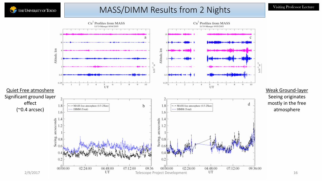
Visiting Professor LectureMASS/DIMM Results from 2 Nights
2/9/2017 Telescope Project Development 16
Weak Ground-layerSeeing originates mostly in the free
atmosphere
Quiet Free atmoshereSignificant ground layer
effect (~0.4 arcsec)
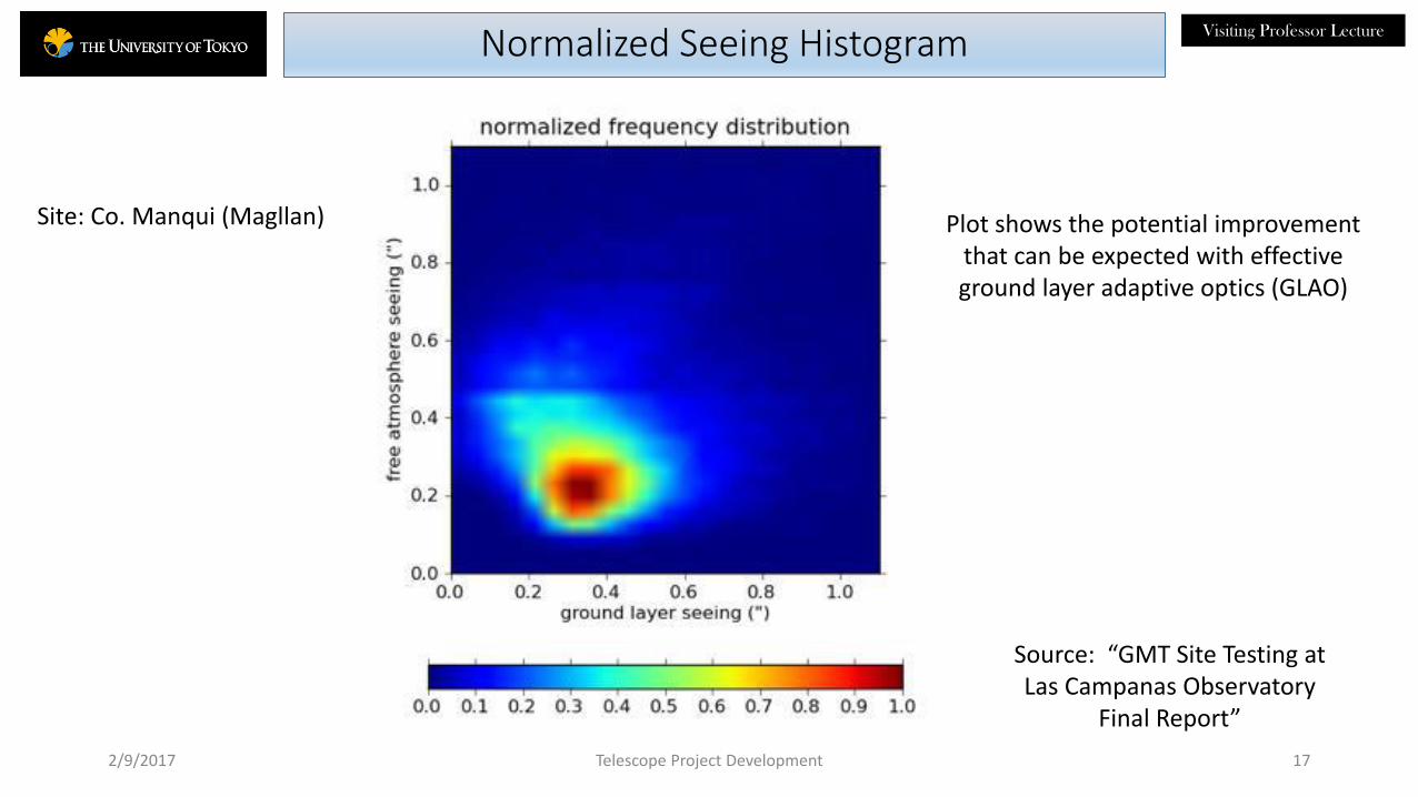
Visiting Professor LectureNormalized Seeing Histogram
2/9/2017 Telescope Project Development 17
Site: Co. Manqui (Magllan)
Source: “GMT Site Testing atLas Campanas Observatory
Final Report”
Plot shows the potential improvement that can be expected with effective ground layer adaptive optics (GLAO)
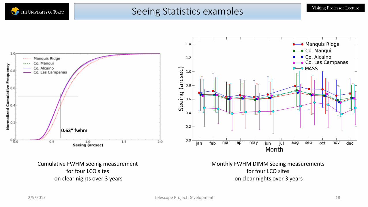
Visiting Professor LectureSeeing Statistics examples
2/9/2017 18
Cumulative FWHM seeing measurementfor four LCO sites
on clear nights over 3 years
Monthly FWHM DIMM seeing measurementsfor four LCO sites
on clear nights over 3 years
0.63“ fwhm
Telescope Project Development

Visiting Professor LecturePrecipitable Water Vapor
• Infrared observations are sensitive to the integrated column density of water vapor (PWV) above the telescope
• Column heights less than 2 mm are optimal for thermal IR obserations
• High altitude sites are preferred if IR capability is a key science driver (e.g. TAO) to get above lower altitude PWV.
• Various instruments and techniques are used for measuring PWV
• 225 Ghz tipping Radiometer
• 20 micron tipping infrared radiometer
• The PWV column height can be calculated from high resolution spectroscopic measurements of stellar water vapor absorption line widths in the band 590-730 nm if a suitably instrumented telescope is available nearby.
2/9/2017 19
225 GHz Tipping radiometer
20 micron IRMA (Infrared Radiometer for Millimeter
Astronomy)Telescope Project Development

Visiting Professor LectureLight Pollution
2/9/2017 20
SW USA and Northern Mexico
• Faint object astronomy requires a dark sky.
• Light pollution from growing metropolitan areas imperils nearby observatories.
• Careful planning involves looking ahead ~50 years to predict city growth and avoid premature obsolescence.
Light pollution maps: http://www.lightpollution.it
Telescope Project Development
Northern Chile
/TAO

Visiting Professor LectureSeismic Considerations
• Prime sites for optical observatories are often located in seismically highly active regions (e.g. Hawaii and Chile)
• Building codes provide design criteria for structures based on local zone classification• These are adequate for conventional buildings in low-medium seismic risk regions.
• Telescopes and enclosures are specialized structures that respond differently to seismic disturbance and require more detailed analysis in seismically high-risk areas.
• Telescope• Telescopes structures are usually stiffness critical rather than strength critical. However, internal
stresses need to be limited to safe values in the event of a major earthquake.
• Ground accelerations will be amplified in high-performance stiff, lowly-damped telescopes. Amplifications of 4 or more at points within the structure are possible.
• Fragile optics and instruments rigidly mounted in the telescope will be subjected to accelerations well in excess of what they experience during normal operation.
• Enclosure• The enclosure upper structure has no internal bracing in the telescope chamber to resist accelerations.
• Openings for the vent windows and shutters weaken the upper structure.
• The structure is interrupted across the azimuth track.
2/9/2017 21Telescope Project Development

Visiting Professor LectureNorthern Chile Seismic Events
2/9/2017 22
Antofagasta Santiago
La Serena
N
ALMA/TAO
LCO
Earthquakes Magnitude 7.0 & greater
South American plate
Nazca plate
Telescope Project Development

Visiting Professor LectureSite Specific Seismic Hazard Analysis (SSSHA)
• SSSHA tasks
• Detailed review of the site geological and topographical characteristics.
• Analysis of ground motion and frequency for recent and historical seismic events in the area surrounding the site.
• Modeling of the propagation paths from areas where seismic sources are likely to originate.
• Computation of the probability of occurrence of seismic events of various magnitudes.
• Generating probabilistic predictions for ground accelerations at the site for use in FEA models.
• Analysis is performed for specified risk criteria and configurations
• Operating Level Earthquake (OLE) with a 200 year mean return period
• Repairs can be made and the facility can be put back in operation in a short time (~weeks).
• Survival Level Earthquake (SLE) with a 500 year mean return period
• The facility will survive without collapsing but repairs could take a long time.
• SSSHA Output
• Response spectra as functions of structure vibration frequency and damping.
• Time series ground accelerations at the pier base.
• Enclosure and telescope structures are analyzed dynamically using the SSSHA accelerations.
2/9/2017 23Telescope Project Development

Visiting Professor LectureShock Response Spectra (SRS) example: LCO
2/9/2017 24
Operating Level Earthquake (OLE)5% damping
Survival Level Earthquake (SLE)5% damping
Typical telescope lowest mode
Typical telescope lowest mode
Telescope lowest mode Telescope lowest mode
2% for a lowly damped structure!
Telescope Project Development
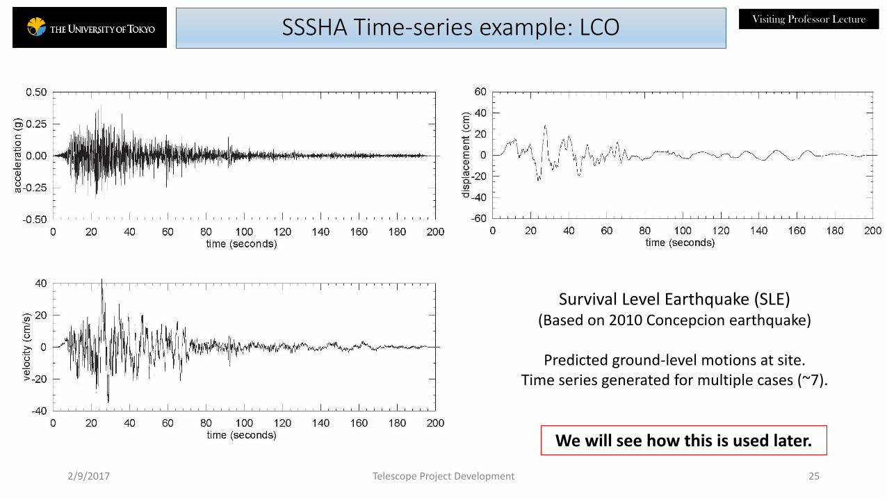
Visiting Professor LectureSSSHA Time-series example: LCO
2/9/2017 25
Survival Level Earthquake (SLE)(Based on 2010 Concepcion earthquake)
Predicted ground-level motions at site.Time series generated for multiple cases (~7).
Telescope Project Development
We will see how this is used later.

Visiting Professor Lecture
Enclosures and Facilities
2/9/2017 Telescope Project Development 26

Visiting Professor LectureTypical Observatory Infrastructure
• Summit
• Enclosure
• Roads, parking and staging areas
• Utilities (power, water systems, chilled liquid plants, cryogens, compressors, communications)
• Environmental monitoring equipment (weather station(s), seeing tower(s), etc.)
• Storage areas (instruments, service and handling equipment, supplies, etc.)
• Maintenance yard and equipment
• Mirror Coating Plant
• Work shops and technical offices
• Dorms and commissary
• Headquarters (in-country and remote)
• Remote observing and data archive sites
2/9/2017 Telescope Project Development 27

Visiting Professor LectureSite Layout
• Best practices
• Optimize enclosure design and orientation to best take advantage of prevailing wind direction.
• Locate heat generating equipment (transformers, compressors, chillers) cross-wind and away from the enclosure.
• Separate heated living spaces and offices, laboratories from the enclosure.
• Coating plant • Periodic mirror washing and/or re-coating is a high risk operation. Locating the plant near or
in the enclosure reduces the risk of damage during transport even if it violates the principle of separating heat producing equipment from the immediate telescope vicinity.
2/9/2017 Telescope Project Development 28

Visiting Professor LectureMagellan Site & Facilities
2/9/2017 Telescope Project Development 29
Clay TelescopeBaade Telescope
Auxiliary Building & Coating Plant
Science Support Offices and Laboratory
Compressors & Chillers
Photo taken from the lodge and dining hall.
Elevation: 2,500 m
• Closely associated facilities at a moderate elevation site.
• Mirror coating plant is on the upper floor of the Auxiliary Building across bridges to the telescope chambers.
• Instrument storage is located on the ground floor in the Auxiliary Building.
• The predominant (80%) wind is from the NE perpendicular to the line joining the two telescopes.
• The sea—level office is in La Serena, Chile.
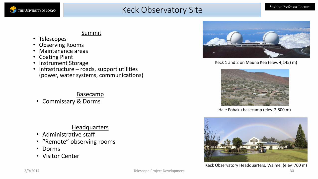
Visiting Professor LectureKeck Observatory Site
2/9/2017 30
Hale Pohaku basecamp (elev. 2,800 m)
Keck Observatory Headquarters, Waimei (elev. 760 m)
Keck 1 and 2 on Mauna Kea (elev. 4,145) m)
Telescope Project Development
Summit• Telescopes• Observing Rooms• Maintenance areas• Coating Plant• Instrument Storage• Infrastructure – roads, support utilities
(power, water systems, communications)
Basecamp• Commissary & Dorms
Headquarters• Administrative staff• “Remote” observing rooms• Dorms• Visitor Center

Visiting Professor LectureEnclosures
2/9/2017 31
• Enclosure types
1. Traditional spherical dome with bi-paring or up-and-over shutters
2. Cylinder or modified cylinder
3. Cube
4. Octagonal
5. Calotte
• Co-rotating
• Co-rotating: telescope and enclosure rotate together (examples: MMT, LBT, Apache Point Observatory)
• Independent: telescope and enclosure rotate independently of each other.
Telescope Project Development
2. Subaru
4. WIYN3. MMT
1. Keck
5. TMT

Visiting Professor LectureEnclosure Functional Requirements
2/9/2017 32
• Protect the telescope and instruments from damage under all operating and survival conditions.
• Open up and rotate to provide an unobscured view over the full telescope azimuth and elevation observing range.
• Shield the telescope from wind turbulence and moonlight.
• Provide a good thermal environment within the telescope chamber during observing.
• Have good aerodynamic design to minimize the seeing effects of ground layer.
• Provide access and equipment for handling and servicing equipment
• Telescope mechanisms
• Optics including mirror re-coating
• Science instruments.
• Provide a safe working environment for personnel.
Telescope Project Development
Visiting Professor LectureSpherical Dome
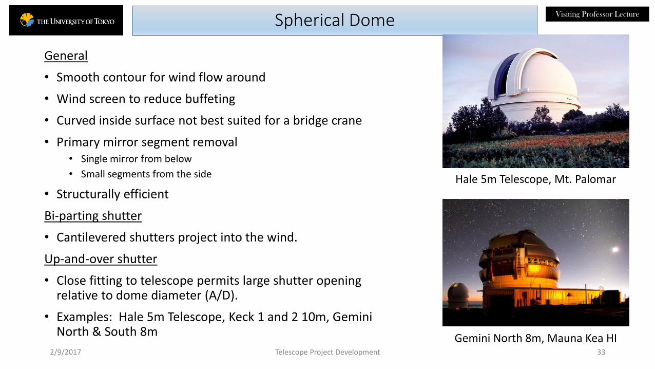
General
• Smooth contour for wind flow around
• Wind screen to reduce buffeting
• Curved inside surface not best suited for a bridge crane
• Primary mirror segment removal• Single mirror from below
• Small segments from the side
• Structurally efficient
Bi-parting shutter
• Cantilevered shutters project into the wind.
Up-and-over shutter
• Close fitting to telescope permits large shutter opening relative to dome diameter (A/D).
• Examples: Hale 5m Telescope, Keck 1 and 2 10m, Gemini North & South 8m
2/9/2017 33
Gemini North 8m, Mauna Kea HI
Hale 5m Telescope, Mt. Palomar
Telescope Project Development

Visiting Professor LectureCylindrical with Bi-parting Shutter
2/9/2017 34Subaru 8m
ESSO 8m VLT
• Smooth air-flow contour around sides
• Accommodates bridge crane• Larger dead air volume at top.
• Bi-parting shutters• Can disrupt air flow around sides for large A/D
• Wind screen required to reduce telescope buffeting
• Vents in upper rotating section for thermal control
• Flat top can collect snow/ice.
• Primary mirror service• Remove single primary mirror from above or below and small
segments from side
• Structurally efficient: Direct load path through the bogeys down to ground
• Rotation: Independent (VLT) and co-rotating (Subaru)
• Examples: VLT, Subaru, TAO
Telescope Project Development

Visiting Professor LectureCo-rotating Cube
• Telescope and enclosure upper structure rotate together
• Minimum internal volume
• Fiber-fed instrument labs and additional technical space on rotating structure
• Cabling between telescope and enclosure simplified
• Bi-parting shutters
• Accommodates a bridge crane
• Squared off walls may create air turbulence at corners.
• Observing floor cantilevered – indirect load paths require extra structure
• Wind vents in rear. Vents in side walls blocked by work spaces.
• Flat top can collect snow/ice.
• Examples: MMT, LBT, ARC 3.5m
2/9/2017 35
MMT 6.5m, Mt. Hopkins
LBT twin 8.4 m, Mt. GrahamTelescope Project Development

Visiting Professor LectureOctagonal
2/9/2017 36
• Close fitting to the telescope
• Large A/D.
• Telescope and enclosure rotate independently.
• Wind screen and moon roof required to reduce telescope buffeting.
• Overhead bridge crane is not practical.
• Primary mirror is removed from below for re-coating.
• Large bi-parting shutters disrupt air flow over the structure.
• Snow/ice can collect on flat top.
• Optimized for thermal performance
• Large (25%-30%) shutter and vent openings for flushing.
• Low-mass, thermally responsive structure
• Flat walls use commercially available insulated panels
• Examples: WIYN 3.5 m, Magellan 6.5 m
WIYN 3.5 m, Kitt Peak AZ
Magellan 6.5m, Las Campanas ChileTelescope Project Development

Visiting Professor LectureCalotte
2/9/2017 37
• The novel calotte design is extremely compact.
• Its smooth exterior, even while open for observing, is significantly less affected by unbalanced wind forces and should shed snow and ice much more quickly than some other enclosure concepts.
• The dome rotates in azimuth about a vertical axis independently from the telescope and the cap rotates on an inclined plane to allow the telescope to look out through the offset opening in the cap in all directions above a minimum elevation angle.
• Wind vents in the side of the dome provide flushing of the telescope chamber.
• Flaps around the aperture reduce wind buffeting at the top end of the telescope.
• A cap (not shown) closes off the dome during the day and in inclement weather.
• An overhead bridge crane is not feasible.
• Mirror segments are removed from the side.Telescope Project Development
TMT
See the automated model in the NAOJ visitor’s gallery at Mitaka.
Visiting Professor Lecture
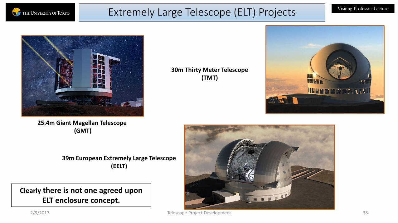
39m European Extremely Large Telescope (EELT)
30m Thirty Meter Telescope (TMT)
2/9/2017
25.4m Giant Magellan Telescope (GMT)
38
Extremely Large Telescope (ELT) Projects
Telescope Project Development
Clearly there is not one agreed upon ELT enclosure concept.

Visiting Professor Lecture
Enclosure Thermal Engineering
2/9/2017 Telescope Project Development 39

Visiting Professor LectureGMT Enclosure PDR Concept
2/9/2017 40Shutters and vents closed Shutters and vents open
• GMT PDR shutter concept
• Vertical front and horizontal top shutters operated independently of each other.
• Telescoping panels could be deployed part way to close down around the telescope beam and to act from above and below as a wind screen and a moonlight shield. Concern: panel mass.
• The enclosure rotates independently of the telescope.
• The structure was analyzed to determine wind flow around and through the structure.
• Wind tunnel testing including surrounding terrain.
• Computation Fluid Dynamics numerical analysis.
• Current enclosure concept uses bi-parting shutters.
Telescope Project Development

Visiting Professor LectureGMT Enclosure Cut-away
Building height: 62 meters
Pier
Swept volumeViewing
angleShutters
Bridge crane
Rails
Hatch
Bogies
2/9/2017 41Telescope Project Development
• The top and front shutters can be closed around the telescope beam to shield the telescope from wind buffeting and moonlight.
• Vent openings in the walls are adjustable to control air flow through the structure.
• The current design uses bi-parting shutters.

Visiting Professor LectureWind Tunnel Testing
• Wind tunnel testing at Cermak, Peterka and Petersen (CPP), Fort Collins CO.
• Scale model tests of the GMT enclosure and telescope
• Turntable top simulated the terrain on site and rotated to investigate flow from different directions.
• 660 pressure taps recorded pressure on the enclosure exterior and interior structure.
• Shutters and vent windows could be opened or masked to simulate various operating conditions.
• Telescope mounted on a 6-axis balance scale to measure wind forces on it.
• Smoke injected to visualize air flow and flushing times.
• Cases examined
• Dome closed, partially open, fully open
• Wind from all directions
• Wind tunnel results
• Determined wind loading for the enclosure design
• Set boundary conditions for CFD analysis.2/9/2017 42
Enclosure and terrain model on turntable
Wind direction
Turntable
Telescope Project Development
Test parameters:
• Terrain & summit facilities
• Vent & shutter configuration
• Wind approach angle
• Telescope elevation angle 60˚

Visiting Professor Lecture
2/9/2017 Telescope Project Development 43
Model Details
(L) Closed enclosure model and terrain on turntable. (Center) 50% open model. (R) 100% open model.
Enclosure base detail showing pressure taps.
GMT model on balance stand.

Visiting Professor LectureFlow Visualization
2/9/2017 44
Shutters and vents 50% open.Ground layer flow under enclosure base.
Smoke wand.
Telescope Project Development
• Smoke is injected up stream of the model to show wind flow through and around the structure and flushing.
• Walls are colored red to enhance visualization.

Visiting Professor LectureCFD Wind Flow analysis
2/9/2017 45
Flow through GMT for the open enclosure, 0°
wind direction, 3 m/s case. Vertical cut.
Telescope Project Development
• Computational fluid dynamics (CFD) analysis calculates the wind flow through the enclosure from the boundary conditions determined from the wind tunnel tests.
windcrane
M1
Visiting Professor Lecture
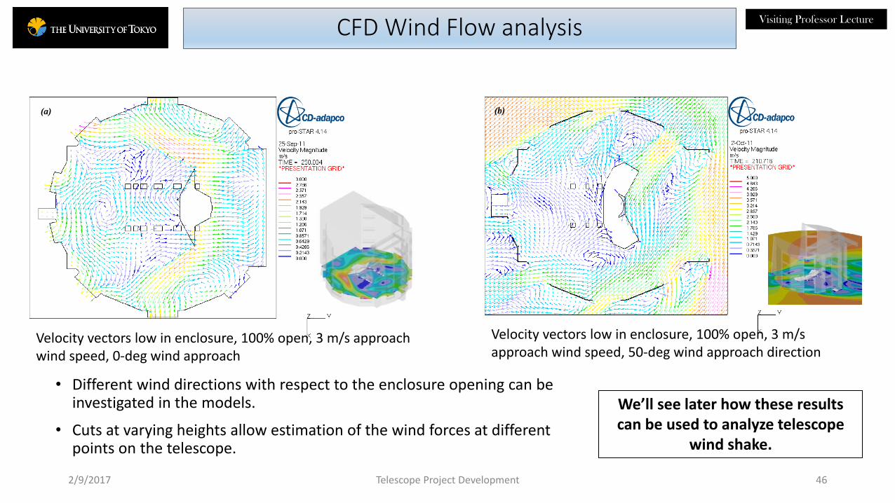
(b)
Velocity vectors low in enclosure, 100% open, 3 m/s approach wind speed, 50-deg wind approach direction
(a)
Velocity vectors low in enclosure, 100% open, 3 m/s approach wind speed, 0-deg wind approach
CFD Wind Flow analysis
2/9/2017 46Telescope Project Development
• Different wind directions with respect to the enclosure opening can be investigated in the models.
• Cuts at varying heights allow estimation of the wind forces at different points on the telescope.
We’ll see later how these results can be used to analyze telescope
wind shake.

Visiting Professor LectureFlow Results affect Enclosure Design
2/9/2017 47Telescope Project Development
• The pressures measured by the taps on the outside of the closed enclosure are used to determine wind loading on the structure in the design of the wall system.
• The thermal performance of the enclosure affects image quality. The wind flow results are used to determine flushing of the structure and estimate the magnitude of this effect.
• Telescope windshake is another major contributor to the image quality budget.
• We’ll see in a later section how the wind flow results are also used to analyze wind shake for various configurations of vents and windscreens.
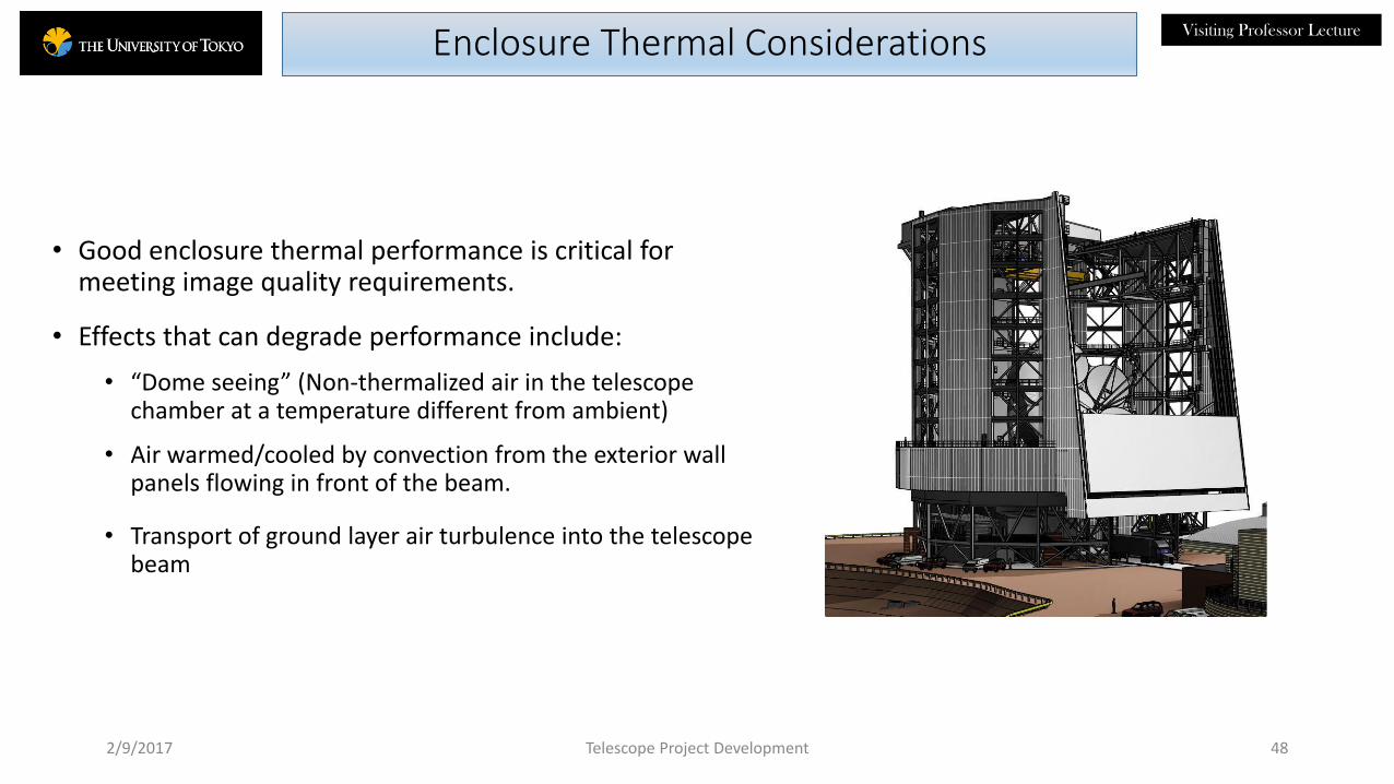
Visiting Professor LectureEnclosure Thermal Considerations
• Good enclosure thermal performance is critical for meeting image quality requirements.
• Effects that can degrade performance include:
• “Dome seeing” (Non-thermalized air in the telescope chamber at a temperature different from ambient)
• Air warmed/cooled by convection from the exterior wall panels flowing in front of the beam.
• Transport of ground layer air turbulence into the telescope beam
2/9/2017 48Telescope Project Development

Visiting Professor LectureDome Seeing
• Dome seeing• Dome seeing is the degradation in image quality (IQ) that results when the air temperature in the telescope chamber
is at a different temperature from ambient.
• IQ contribution = 0.1 T1.2 (arc-sec FWHM/K) where T = Tchamber – Tambient
• Tave < 0.22 K for a 0.017 arc-sec FWHM dome seeing allocation in the GMT image quality budget.
• Heat sources• Powered sources (pumps, motors, fans, electronics, etc.)
• Cooling of the telescope structure (ϯ)
• Cooling of the internal dome structure (ϯ)
• Heat conduction and convection from sources in the base of the enclosure
• Cooling mechanisms• Wind forced ventilation (ϯ)
• Active cooling of the structure
• Radiative losses to the sky through the shutters and vents
• Radiation to the night sky will cool the external skin of the enclosure.• Air blowing across the shutter opening cooled by the outside skin will also degrade seeing.
(ϯ) could be positive or negative depending on the sign of the temperature difference.
2/9/2017 49
References: Racine, R., et. Al. 1991Zago, SPIE 2871, 7017Vogiatzis, SPIE 6271Pazder, SPIE 7017
Telescope Project Development

Visiting Professor LectureSimple Heat Balance Calculation
2/9/2017 Telescope Project Development 50
• Calculate the net heat gain/(loss) in the telescope chamber that will cause dome seeing.
• Heat sources
• Cooling/(heating) of the telescope and dome structure
• Active sources
• Neglect heat conduction/convection from below
• Cooling mechanisms
• Wind driven conductive air flow through the shutters and vents.
• Radiation to the night sky.
• Model assumptions:
• Enclosure pointed away from the wind.
• Shutters may be closed down to approx. 50% open to throttle ventilation and reduce radiation losses.
• Vents can be adjusted from 0% to 100% open.
• Air flow through enclosure is the projected vent and shutter open area
• Steady-state ambient air temperature change rate.
wind
GMT

Visiting Professor Lecture
51
Heat Released as a Function of Temperature Rate of Change (kW)
Effective
Mass
Power
per
K/hr
T/t (K/hr)
10% 25% 50% 75% 90%
Heat Sources metric
tons kW/K/hr
-0.80 -0.44 -0.12 0.22 0.67
Telescope
Structure 680 92 73 40 11 -20 -62
Enclosure
Structure 1888 255 204 112 31 -56 -171
Active Sources na 10 10 10 10 10 10
Total (kW) 287 163 52 -66 -222
Telescope Project Development
GMT Heat Production
• Nighttime temperature rates of change statistics for GMT/LCO
• Heat transport from below neglected.
• Only enclosure interior structure contributes to the heat load.
• Power is calculated from the steady-state rate of heating/cooling and the heat capacity of the enclosure and telescope steel.
• Allowance is made for the fact that some parts of the telescope (ie. M1 assembly) are actively cooled.

Visiting Professor Lecture
52
Air Temperature Rise (K) – Vents 100% Open
Ambient Air Heating/cooling Rate
10% 25% 50% 75% 90%
K/hr
-0.80 -0.44 -0.12 0.22 0.67
Wind speed Heat Production (kW)
Percentile speed P/K 287 163 52 -66 -222
(m/s) (kW/K) (K) (K) (K) (K) (K)
10% 1.6 1,133 0.25 0.14 0.05 -0.06 -0.20
25% 4.0 2,833 0.10 0.06 0.02 -0.02 -0.08
50% 6.5 4,564 0.06 0.04 0.01 -0.01 -0.05
75% 9.4 6,610 0.04 0.02 0.01 -0.01 -0.03
90% 12.4 8,719 0.03 0.02 0.01 -0.01 -0.03
Telescope Project Development
Air Temperature Rise with Wind Flushing –100% Open
GMT spec. Tmax = 0.22 K
• Nighttime wind speed statistics for GMT/LCO
• Wind approaching from the side or back.
• Ventilation windows 100% open.
• P/K scales linearly with projected vent openings
• Temperature rise is calculated from the volume rate of air exchange, heat capacity of the air, and the input heat load.
• Radiation losses are not included here.
Visiting Professor Lecture
53
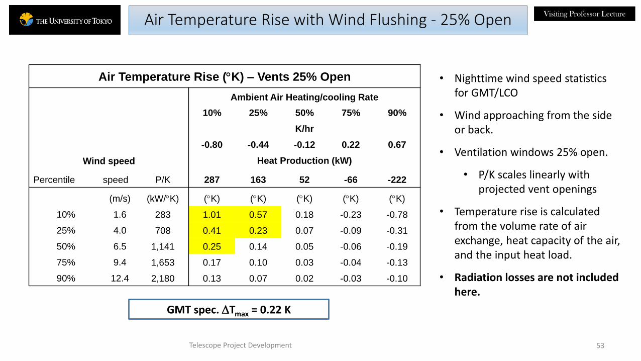
Air Temperature Rise (K) – Vents 25% Open
Ambient Air Heating/cooling Rate
10% 25% 50% 75% 90%
K/hr
-0.80 -0.44 -0.12 0.22 0.67
Wind speed Heat Production (kW)
Percentile speed P/K 287 163 52 -66 -222
(m/s) (kW/K) (K) (K) (K) (K) (K)
10% 1.6 283 1.01 0.57 0.18 -0.23 -0.78
25% 4.0 708 0.41 0.23 0.07 -0.09 -0.31
50% 6.5 1,141 0.25 0.14 0.05 -0.06 -0.19
75% 9.4 1,653 0.17 0.10 0.03 -0.04 -0.13
90% 12.4 2,180 0.13 0.07 0.02 -0.03 -0.10
Telescope Project Development
Air Temperature Rise with Wind Flushing - 25% Open
GMT spec. Tmax = 0.22 K
• Nighttime wind speed statistics for GMT/LCO
• Wind approaching from the side or back.
• Ventilation windows 25% open.
• P/K scales linearly with projected vent openings
• Temperature rise is calculated from the volume rate of air exchange, heat capacity of the air, and the input heat load.
• Radiation losses are not included here.

Visiting Professor Lecture
54
GMT Radiational Cooling
Radiation to the cold night sky will cool the interior of the enclosure.
Shutter & vent openings
• Upper shutter (fully opened) 1,390 m2
• Vertical shutter (fully opened, 50% sky view factor) 1,500 m2
• Vents (fully opened , 50% sky view factor) 1,828 m2
Radiative coefficient: 70 W/m2
Cooling rate:
• Shutters 50% open, vents closed * 56 – 97 kW
• Shutters and vents 50% open * 116 -161 kW
• Shutters and vents 100 % open 213 kW
• Compare to telescope heat load (previous slide) -222 kW to +287 kW
Conclusion: Radiation is a significant contributor to the heat balance within the telescope chamber that can offset heat sources.
2/9/2017 Telescope Project Development
* Depends on telescope zenith angle
Visiting Professor LectureCFD Thermal Modeling
• The heat balance calculation indicates that the high level of flushing in the GMT enclosure provides a good thermal environment for the telescope with adjustability for different wind conditions and orientation with respect to wind direction.
• A heat balance calculation gives only a first-look estimator of dome seeing effects.
• The locations of heat sources and the transport of heated air through the telescope beam requires a more sophisticated analysis to get an accurate assessment of image quality effects.
• Computation fluid dynamics models coupled with a model of wavefront propagation through the shutter into the telescope.
• Estimate compensation of dome seeing by the adaptive optics system.
• Compare to the appropriate IQ error budget.
• References:• “Dome CFD Analysis”, Doc. E-TRE-IDO-327-5058-1, ESSO feed study for E-ELT, 2014. • “Enclosure and Facilities System Preliminary Design Report”, GMT-EF-RVW-00406. 2013.• and other projects.
2/9/2017 Telescope Project Development 55

Visiting Professor Lecture
56
Enclosure Thermal Control Best Practices
• Raise openings above the boundary layer.
• Minimize the thermal mass of the telescope and enclosure structure.
• Maintain the daytime inside air at the predicted early-evening ambient temperature.
• Seal & insulate the observing floor to prevent heat influx from below.
• Promote wind-forced ventilation to remove heat from the enclosure at night and drive the inside temperature to ambient.
• Seal & insulate walls & openings to prevent daytime heat influx.
• Trap active sources of heat within the enclosure.
• Apply low emissivity coatings around shutter & vent openings to reduce over-cooling of these surfaces from radiation to the cold sky.
• MMTO Technical Memorandum No. 81-1, 1981
• Gemini Project Document No. RPT-TE-G0039.
2/9/2017 Telescope Project Development
Relief Louver
Return Air
AHU
Anticipated Airflow
AHU
Active daytime cooling• Expensive and may not be necessary
with other measures.• Not implemented on Magellan.

Visiting Professor Lecture
Magellan Enclosure Development
2/9/2017 Telescope Project Development 57

Visiting Professor LectureMagellan Enclosure Concept
2/9/2017 Telescope Project Development 58
Bi-parting shutters
Auxiliary Buildingwith Coating Plant
and connecting bridge to
enclosures
Rotating dome
Fixed baseOpen below
Baade Telescope Clay Telescope
Ventilation louvers in fixed and
rotating structures
Exhaust tunnels and fans below grade
Insulated wall panels
Reflective tape on upper structure
Visiting Professor LectureEnclosure Engineering & Design
• Enclosure design usually starts with a baseline concept developed through engineering and cost trade studies initiated by the project during the Conceptual Design Phase.
• An architectural/engineering (A/E) firm is contracted to advance the concept through preliminary design (20% completion) including analyses of performance, cost and schedule.
• More than one concept may be developed to this level of maturity in which case a down-select takes place.
• The preliminary design should be compliant with level 3 requirements including interface control documents and ready for final design.
• Final design• 80% completion
• The design is completed to a state where it can be handed off to a contractors for construction.
• Review
• Contracting strategy• The procurement is broken down into logical bid packages (enclosure structure, foundations, civil works, etc.)
• A/E prepares tender documents for construction in collaboration with the Project and assists in the procurement process.
• Carnegie acted as its own construction manager on the Project.
2/9/2017 Telescope Project Development 59

Visiting Professor LectureSite Work
• Survey and Geotechnical measurements
• Hire local contractor to do the site work
• Site clearing and grading
• Staging
• Worker’s camp and contractor’s offices
• Laydown areas
• Access roads
• Concrete batch plant
• Temporary power
• Civil works (roads, water systems)
• Power and communications systems
• Foundations and the pier.
2/9/2017 Telescope Project Development 60
GMT Site
Worker’s Camp

Visiting Professor LectureEnclosure Construction
• Enclosure structure• The steel structure for the fixed and rotating parts of the Magellan enclosure was fabricated at Schwartz
Hautmont in Barcelona.
• They provided the rotation mechanisms, shutters, dome cranes, vent windows and wind screens.
• They also fabricated the steel structure for the Auxiliary Building.
• The shutters and azimuth track and bogies were assembled and tested separately in their yard but a full assembly of the enclosure was not done in Spain.
• Other parts of the enclosure and Auxiliary Building were procured from vendors separately and first assembled on site by the project.
• Insulated wall panels
• Windows and doors
• Building exhaust fan
• Mechanical systems
• Equipment elevator
• Controls
• The enclosure was assembled on site using 50 ton hydraulic and 140 ton mobile cranes purchased by the project and a local assembly crew supervised by the Project.
2/9/2017 Telescope Project Development 61

Visiting Professor LectureMagellan 2 Enclosure Assembly on Site
2/9/2017 Telescope Project Development 62

Visiting Professor LectureMagellan 2 Enclosure Assembly on Site
Of course, it isn’t so pleasant assembling the enclosure on some days!
2/9/2017 Telescope Project Development 63
SNOW!
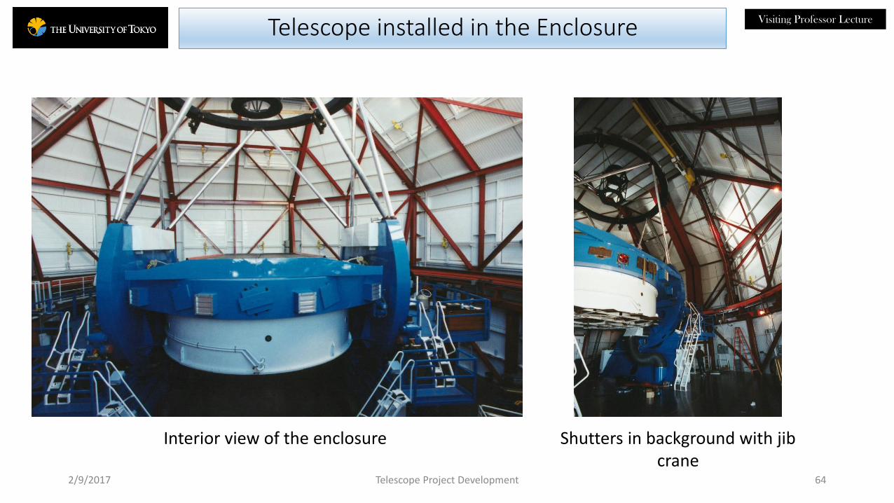
Visiting Professor LectureTelescope installed in the Enclosure
2/9/2017 Telescope Project Development 64
Shutters in background with jib crane
Interior view of the enclosure

Visiting Professor Lecture
2/9/2017 Telescope Project Development 65
Assembled Magellan Enclosures
But eventually the enclosures are ready
for telescope installation and commissioning.

Visiting Professor Lecture
End of Session 3
2/9/2017 Telescope Project Development 66

Visiting Professor LectureBACKUP
2/9/2017 67Telescope Project Development

Visiting Professor Lecture
Velocity vectors above telescope, 25% open, 3 m/s approach wind speed, 0-deg wind approach
2/9/2017 68
(b)
Velocity vectors above telescope, 25% open, 3 m/s approach wind speed, 50-deg wind approach direction
CFD windflow analysis
Telescope Project Development