telegragher’s equations group - a. usman nofal kh. muhammad mashood khawaja muhammad abdul rahman...
TRANSCRIPT

Telegragher’s EquationsGroup - A

Group Members• Usman Nofal• Kh. Muhammad Mashood• Khawaja Muhammad Abdul Rahman• Abdullah Amin• Yahya Ahmad• Syeda Sana Zafar• Taimoor Tahir• Mehwish Anwar• Ali Zargham• Saqib Javed• Osama Dastgir Mallick• Faisal Naseer• Muhammad Rameez
Introduction
• Set of coupled, Linear Differential Equations.
• They give information about voltage and current in an electrical transmission line.
• They depend on distance (x) and time (t).

Why Transmission Lines???
Imagine two ICs as shown:-
When the voltage at A changes state, does that new voltage at B changes simultaneously?
No, of course NOT. Due to Propagation delays which is not ignorable in long transmission lines.
Why Transmission Lines (Contd.)• The propagation of voltage signals is modeled as
Transmission Line.• Transmission Line Equations are used to show that
voltage and current can propagate along a Transmission Line as waves.
Fantastic!
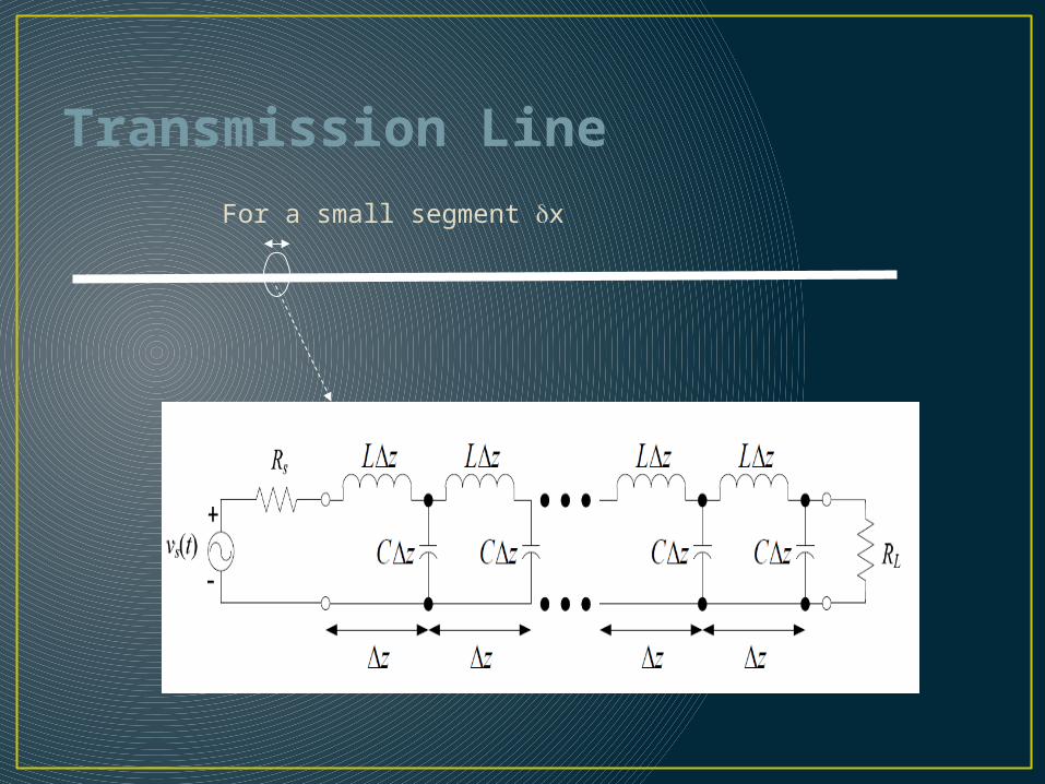
Transmission Line
For a small segment x

Transmission Line (Contd.)
𝑖𝑐
R’ z L’ z
G’ z C’ z
z
V(z)
𝑖𝐺
i(z+ z)
V(z+ z)
+
-
+
-
Voltage resonates between inductor and capacitor. This effect passes on.Resistor contribute only for the loss in the lines.
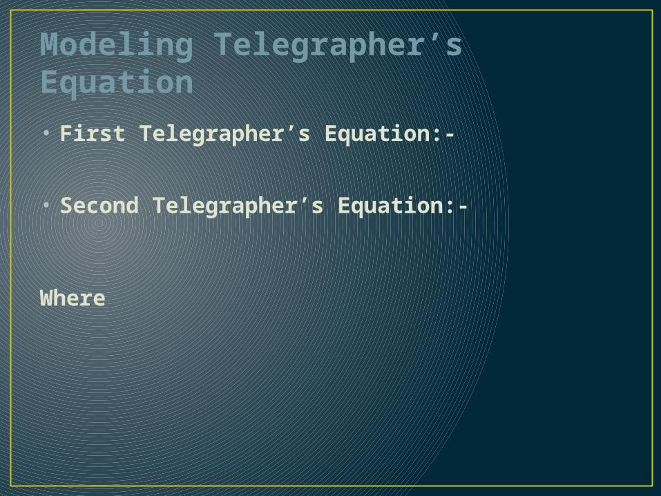
Modeling Telegrapher’s Equation• First Telegrapher’s Equation:-
• Second Telegrapher’s Equation:-
Where

Derivation
−𝝏𝒗𝝏 𝒛
=𝑹 ′ 𝒊 (𝒛 )+𝑳′ 𝝏 𝒊𝝏 𝒕
For 1st Telegrapher Equation we apply KVL, we get:-
−𝒗 (𝒛 )𝛁 𝒛
−𝑹 ′ 𝒊 (𝒛 )−𝑳′ 𝝏 𝒊 (𝒛 )𝝏𝒕
−𝒗 (𝒛+𝛁 𝒛 )
𝛁 𝒛=𝟎
By manipulation we get:-
First order telegrapher’s equation for voltage

Derivation (Contd.)• For 2nd Telegrapher Equation we apply KCL on the
upper node:-
By manipulation we get:-
First order telegrapher’s equation for current

Derivation (Contd.)• As we know that
So, Telegrapher’s equations in frequency domain:-

Derivation (Contd.)• A single wave equation is introduced to combine
these two equations and solve them.• We partially derivate both equations w.r.t z
As we know
So,

Relation with waves
Where = complex propagation constant
(Neper/m) (rad/m)
Positive wave propagation:-
Negative wave propagation:-
Derivation (contd.)
We know that
So,
We also know that
So, we substitute I(z)
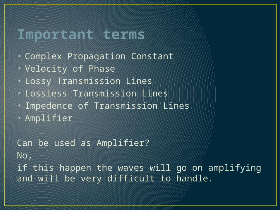
Important terms• Complex Propagation Constant• Velocity of Phase• Lossy Transmission Lines• Lossless Transmission Lines• Impedence of Transmission Lines• Amplifier
Can be used as Amplifier?No, if this happen the waves will go on amplifying and will be very difficult to handle.
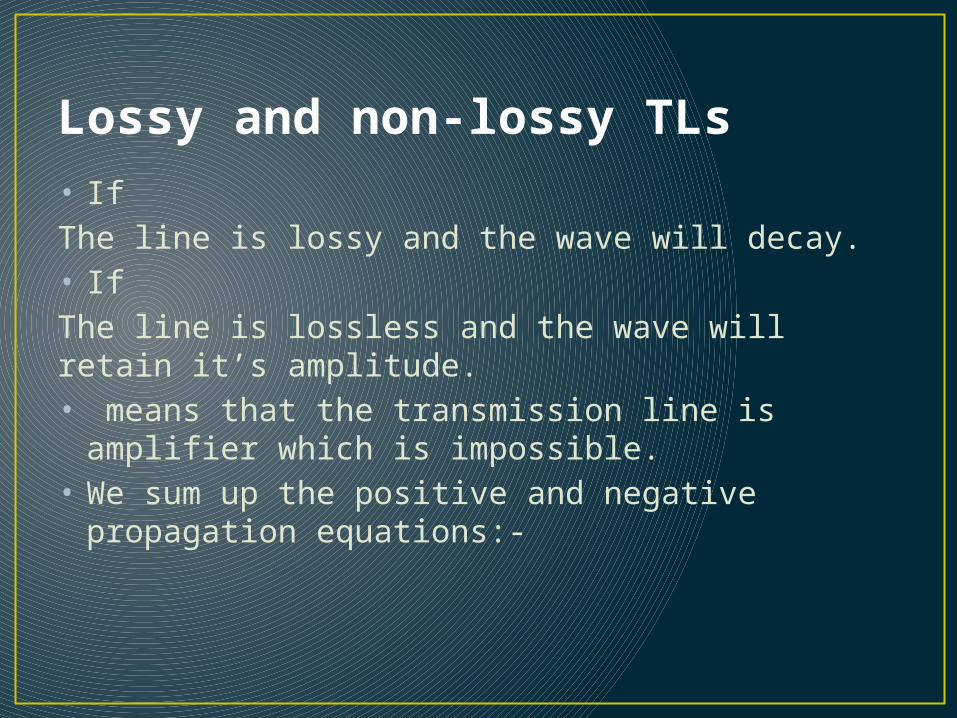
Lossy and non-lossy TLs• If The line is lossy and the wave will decay.• If The line is lossless and the wave will retain it’s amplitude.• means that the transmission line is amplifier
which is impossible.• We sum up the positive and negative propagation
equations:-

Impedances
As we know that
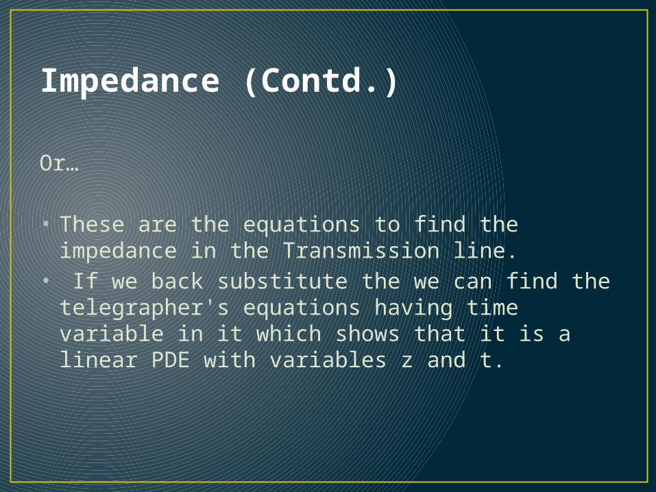
Impedance (Contd.)
Or…
• These are the equations to find the impedance in the Transmission line.
• If we back substitute the we can find the telegrapher's equations having time variable in it which shows that it is a linear PDE with variables z and t.

General form of telegrapher’s equation
Which in our case
If we link with our previous knowledge we have studied wave equation as
The equation can be linked with this equation if both are equal to zero.
Thus telegrapher/ transmission lines equation are generally the wave equation which some different subscripts.
Note: Here can be either current I or voltage V.
General form of telegrapher’s equation (contd.)
Where • c

General Solution• u(x,t)=(x)+(x)
Which you are familiar with, as the common solution to the wave equations Here ‘c’ represents the same thing as in wave.
In waves c represent the speed or velocity of wave
Here c represent the phase velocity which has the same definition as described in the previous slide.
Applicability
The transmission line model can be used to solve many types high frequency problem, either exactly or approximately:
• Coaxial cable• Two-wire• Microstrip, stripline, coplanar waveguide, etc.

Questions