telecommunications distribution methods and standards
TRANSCRIPT

City of Seattle Department of Information Technology
Telecommunications
Distribution Methods and Standards
May 2005
City of Seattle Telecommunications Distribution Methods and Standards
05/13/05 Page 1
Table of Contents
1. About This Document..............................................................................................................3 1.1. Purpose of This Document ................................................................................................3 1.2. Who Should Use This Document.......................................................................................3 1.3. Questions Regarding This Document ................................................................................3 1.4. How to Update This Document ..........................................................................................3
2. Infrastructure Design...............................................................................................................4 2.1. Entrance Room ..................................................................................................................4 2.2. Communications Room......................................................................................................5 2.3. Riser System......................................................................................................................5 2.4. Horizontal Feed System (HFS) ..........................................................................................6 2.5. Horizontal Distribution System (HDS)................................................................................6
3. Communications Room...........................................................................................................8 3.1. Design Guidelines ..............................................................................................................8 3.2. Cable Tray Design ...........................................................................................................13
3.2.1. Rod Mounts ..........................................................................................................14 3.2.2. Angle Support Brackets........................................................................................15 3.2.3. Triangular Support Brackets.................................................................................16 3.2.4. Ground Brackets...................................................................................................16 3.2.5. Junction Splice Kits ..............................................................................................16 3.2.6. Butt-Splice Kits .....................................................................................................17 3.2.7. Brace Plates .........................................................................................................17 3.2.8. J–Bolts ..................................................................................................................18
3.3. Backboard Design............................................................................................................18 3.4. Cable Management..........................................................................................................21 3.5. Equipment Rack Design...................................................................................................21
3.5.1. General Rack Specifications ................................................................................21 3.5.2. Equipment Rack Layout in Communications Rooms ...........................................22
3.6. Equipment Cabinets.........................................................................................................23 3.7. Power ...............................................................................................................................23 3.8. Seismic Bracing ...............................................................................................................24 3.9. Grounding ........................................................................................................................24
4. Riser System...........................................................................................................................26 4.1. Riser Installation...............................................................................................................26 4.2. Fiber Riser........................................................................................................................27 4.3. Fiber Distribution Units.....................................................................................................28 4.4. Riser Labeling ..................................................................................................................28
5. Horizontal Distribution System.............................................................................................29 5.1. Cable Systems .................................................................................................................29 5.2. Cable Runs ......................................................................................................................33 5.3. Wiring Blocks ...................................................................................................................33

City of Seattle Telecommunications Distribution Methods and Standards
05/13/05 Page 2
5.4. Cable Hardware to Backboard.........................................................................................34 5.5. Labeling Blocks ................................................................................................................35 5.6. Patch System or Cross-Connects....................................................................................36
5.6.1. VisiPatch 119 4-Pair Adapter Cords.....................................................................36 5.6.2. VisiPatch Cable Packages ...................................................................................37 5.6.3. Cross-Connect Wire Color Codes ........................................................................38
5.7. Work Area Jacks/Outlets..................................................................................................38 5.7.1. Types of Jacks/Outlets .........................................................................................39 5.7.2. Labeling Cables....................................................................................................39 5.7.3. Labeling Jacks/Outlets .........................................................................................39
5.8. Basic Cabling Concepts ...................................................................................................40 5.9. Cabling Guidelines ...........................................................................................................41 5.10. Crossover Cables.............................................................................................................42
5.10.1. How to Make a Crossover Cable..........................................................................42 5.10.2. Crossover Cable Wiring........................................................................................43 5.10.3. Cat5 Pin Assignments ..........................................................................................43
5.11. UTP Cables......................................................................................................................43 6. Glossary..................................................................................................................................45

City of Seattle Telecommunications Distribution Methods and Standards
05/13/05 Page 3
1. About This Document
This section describes the purpose, scope, and use of this document, as well as the procedure for updating it.
1.1. Purpose of This Document
The DoIT Network Services group supports telecommunications in a multi-product, multi-vendor environment in a commercial building. The purpose of this document is to provide guidelines and standards for the City of Seattle’s:
• Telecommunications equipment
• Cabling
• Planning and installation of structured cabling systems
1.2. Who Should Use This Document
This document is intended for use by City of Seattle employees, vendors, and contractors who install, upgrade and/or support telecommunications equipment and cabling.
1.3. Questions Regarding This Document
If you have further questions regarding any the building systems discussed in this document, call or e-mail the appropriate contact listed in the table below.
Building Systems Contact Name Work Number E-mail Address
HORIZONTAL DISTRIBUTION SYSTEM Sheila Shelton (206) 386-9777 [email protected]
Kris Henry-Simmons (206) 684-0265 [email protected] RISER SYSTEM
Andy Stankovics (206) 386-4029 [email protected]
GROUND/POWER/SEISMIC Doug King (206) 684-7733 [email protected]
OUTSIDE PLAN Kris Henry-Simmons (206) 684-0265 [email protected]
TELEPHONE SERVICES Kelly Walker (206) 233-2787 [email protected]
DATA NETWORK SERVICES Candis Frederick (206) 386-0097 [email protected]
Kelly Walker (206) 233-2787 [email protected]
Kris Henry-Simmons (206) 684-0265 [email protected]
Doug King (206) 684-7733 [email protected]
Candis Frederick (206) 386-0097 [email protected]
COMMUNICATION ROOM DESIGN
Andy Stankovics (206) 386-4029 [email protected]
1.4. How to Update This Document
For updates to this document, contact Candis Frederick.

City of Seattle Telecommunications Distribution Methods and Standards
05/13/05 Page 4
2. Infrastructure Design
This section discusses the five major components of infrastructure design, as illustrated in Figure 1: Entrance Room, Communications Room, Riser System, Horizontal Distribution System – Cable, and Horizontal Distribution System – Station Conduit and Outlets.
Figure 1: Typical Building Communication Infrastructure Design
2.1. Entrance Room
The Entrance Room (ER) is the most permanent element in the communications infrastructure.
FUNCTION • Provides racking equipment to terminate cabling that enters
the building.
• Provides a controlled environment to house telecommunication equipment, connecting hardware and splice closures.
• Provides a point-of-presence for vendors (local vendors, Qwest, Winstar, etc.)
• Interconnects internal telecommunications systems between buildings.
• Functions as the Main Distribution Frame (MDF) for building internal telecommunication systems.

City of Seattle Telecommunications Distribution Methods and Standards
05/13/05 Page 5
LOCATION Near a permanent feature (i.e. staircases and airshafts for utilities, ventilation, and elevators), or in the core area.
DESIGN • This area must be designed exclusively for communications services, and cannot be shared with electrical components, janitorial services, or fire alarm systems.
• Plumbing, electrical, and ventilation systems must be routed outside of this room.
2.2. Communications Room
FUNCTION • Provides a controlled environment to house telecommunication equipment, connecting hardware and splice closures.
• Provides space and access to pathways that support voice, data, video, and radio services.
• Provides termination of horizontal cable distribution on compatible connection hardware.
• Provides termination of riser cabling from the MDF.
• Functions as the Intermediate Distribution Frame (IDF) for the buildings telecommunication systems.
LOCATION Near a permanent feature (i.e. staircases and airshafts for utilities, ventilation, and elevators), or in the core area.
DESIGN • Communications Rooms perimeters must not exceed 250 ft. from the farthest distance point.
• Provide direct access from public hallways.
2.3. Riser System
FUNCTION • Functions as the building's vertical connection between the MDF and IDF.
• A backbone distribution system is the part of a distribution system that provides connection between equipment rooms, telecommunications rooms and telecommunications service entrance facilities.
• The pathway is to be a continuous vertical path free of horizontal runs extending from the MDF to the roof.

City of Seattle Telecommunications Distribution Methods and Standards
05/13/05 Page 6
LOCATION • The riser pathway is incorporated into the initial design and construction of the building.
• The placement of the riser shall provide convenient access to all communications rooms within the building.
• Near permanent feature (i.e. staircases and airshafts for utilities, ventilation, and elevators), or in the core area.
• Closets within buildings, 2-story building and multi-story building.
DESIGN • Star wiring topology.
• Sleeves used for the floor penetrations are to have a minimum 4” I.D. with bushings on both ends. The cabling utilized in the building riser must be riser rated or better.
2.4. Horizontal Feed System (HFS)
FUNCTION • Provides horizontal copper and fiber feed between two Communication Rooms.
• Provides a physical means for transporting telecommunications signals between the telecommunications outlet/connector in the work area and the horizontal cross-connect in the telecommunication room.
LOCATION Communication Rooms
DESIGN
2.5. Horizontal Distribution System (HDS)
FUNCTION Provides horizontal cable from the Communication Rooms to the workstation.
LOCATION Communication Rooms to the workstation.

City of Seattle Telecommunications Distribution Methods and Standards
05/13/05 Page 7
DESIGN • All pathways considered must run in the most direct route as possible (usually parallel to building lines); all branches from the parallel line should have 90-degree branches to individual groups of workstations.
• The maximum horizontal distance from the distribution termination block to the work-in area jack/outlet must not exceed 250 ft., dependent of media type. This is the distance for Category 5e copper standard, currently in use and the standard for all new cable runs.
• ¨The maximum distance from the cabling modular plug to the distribution termination block, which include cross-connects or patch cables within the IDF must not exceed 40ft.
• The maximum distance from the jack/outlet to the workstation must not exceed 25ft.
• EIA/TIA 568B
• UTP must not exceed 100 meters.
• Multimode fiber must not exceed 2 kilometers (1.2 miles)
• No splitting pairs. Each cable is terminated on a single jack.
• UTP cables must meet Category 5e standards.
• Include in the HDS distance, is the data whips, jumpers, cable runs, and station cable.

City of Seattle Telecommunications Distribution Methods and Standards
05/13/05 Page 8
3. Communications Room
The Communications Room provides many functions for the cabling system and is often treated as a distinct sub-system within the hierarchical cabling system. The section lists the cabling practices and guidelines for cross-connects and inter-connections.
The cross-connection of horizontal cable terminations for data, phone, and other services use jumpers or patch cords. This allows flexible connectivity when extending various services to the work area outlet.
3.1. Design Guidelines
SIZE Two types of Communications Rooms are acceptable.
• Standard “walk-in” Communications Room.
• “Shallow” Communications Rooms with double doors opening into the hallway.
NUMBER PER FLOOR
The number of Communications Rooms per floor will be the minimum required to support the potential assignable square footage.
There will be at least one Communications Room per floor, except when:
• The area exceeds the farthest floor distance.
• The maximum cable distance exceeds 250 ft.
• Communications Room space is limited.
CEILINGS False ceiling may or may not be installed, depending on the Fire code jurisdiction of that Building.
DOORS All doors must be 36 inches wide, and 6-feet 8-inches high.
• Walk-in Communications Rooms: Locate the door on one the shorter walls of the room. The door should not be centered on the wall. Locate door at the farthest corner and opposite distance from the backboard. The door must not swing in a manner that restricts access or blocks riser conduits, cable trays, or the main backboard.
• Shallow Communications Rooms: Provide double doorways that open outward. Fix the left door, top and bottom, with deadbolts.
ENVIRONMENT CONTROLS
Maintaining strict control over environmental factors is important to ensure reliability of equipment in Communications Rooms. The table below lists acceptable environment parameters.
• Temperature: Between 68°F and 72°F
• Humidity:
FIRE RATING Fire rating of walls and doors must comply with code. 2hr firewalls must have conduit down to the outlet box (usually provided by the Electricians) and must be protected by fire wool.
City of Seattle Telecommunications Distribution Methods and Standards
05/13/05 Page 9
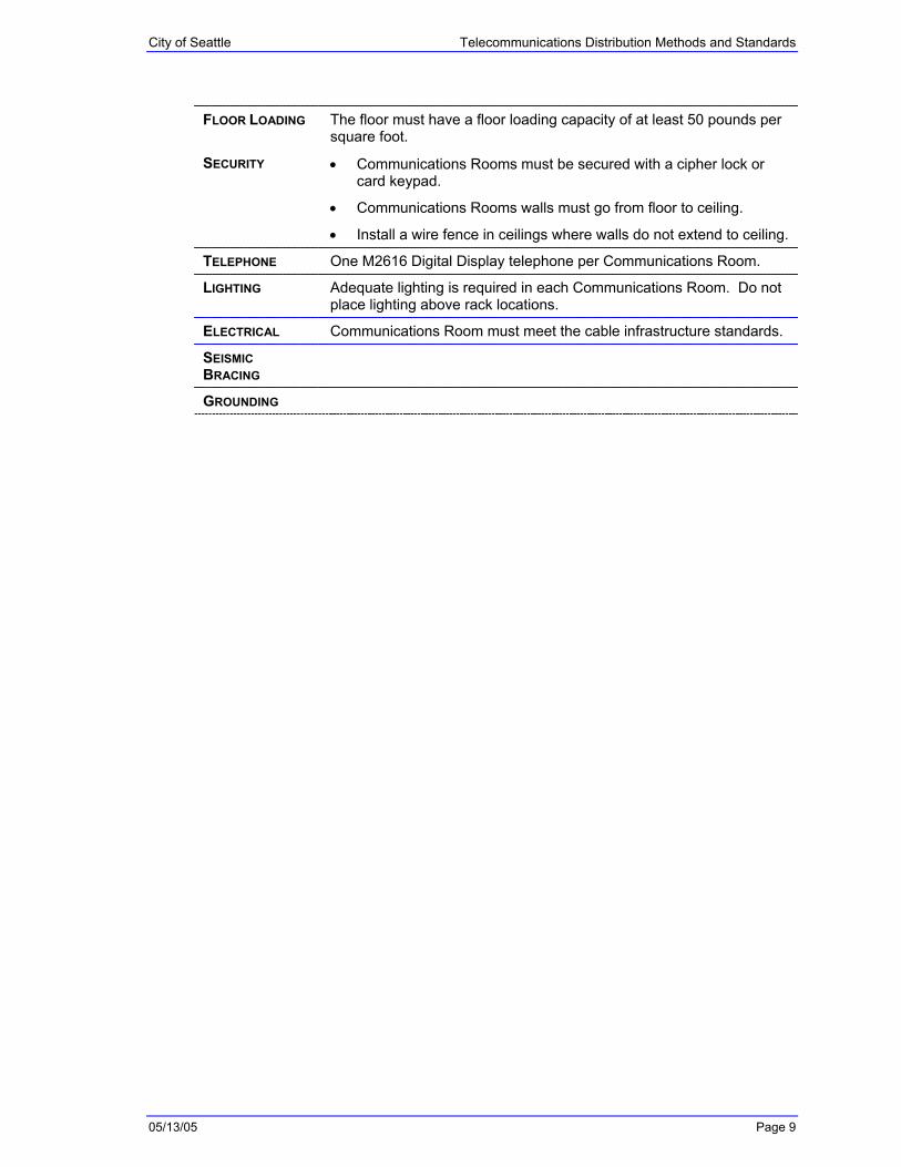
FLOOR LOADING The floor must have a floor loading capacity of at least 50 pounds per square foot.
SECURITY • Communications Rooms must be secured with a cipher lock or card keypad.
• Communications Rooms walls must go from floor to ceiling.
• Install a wire fence in ceilings where walls do not extend to ceiling.
TELEPHONE One M2616 Digital Display telephone per Communications Room.
LIGHTING Adequate lighting is required in each Communications Room. Do not place lighting above rack locations.
ELECTRICAL Communications Room must meet the cable infrastructure standards.
SEISMIC BRACING
GROUNDING

City of Seattle Telecommunications Distribution Methods and Standards
05/13/05 Page 10
BACKBOARD Provide backboard around all four walls.
Backboard planning:
• Size of wall that will support wiring blocks.
• Total number of cables per jacks, phone, data, riser system.
• How many wiring blocks?
• Workgroup floor capacity. How many blocks for growth?
• Select one of the backboard designs that best fits requirements. See backboard design options.
Figure 2: Backboard
EQUIPMENT RACKING
Provide floor mount racks to mount riser system and phone and data hardware. Quantity and type (width) of racks are based on the hardware specifications.
• Minimum requirement is one 7x19” floor mount rack.
• Double-sided vertical cable management on both sides of rack.
• Stand-alone racks with no above cable tray bracing must use the “Rack Seismic Gusset Kit”.
CABLE TRAY Provide cable tray around the periphery of the Communications Room to support and distribute cable within the room. The size and configuration may not require cross-room segments. Tray must be located 6-inches from the backboard.

City of Seattle Telecommunications Distribution Methods and Standards
05/13/05 Page 11
CONDUITS Conduits must be used for cabling that leaves the Communications Rooms. Conduits are mandatory for fire stopping between floors.
• Locate vertical riser conduit along the sidewall to the right of the backboard.
• 4” conduits support an average of 50-60 Category 5 cables.
• Conduits must be at least 6” from the wall to the right of the backboard (Riser).
• Conduits must be at least 6” from the wall below or above the distribution horizontal cabling blocks.
• Fire Block Puddy or Brick must be used at cable entry points, as shown in Figure 3.
FIRE STOPPUDDY(BRICK)
4" CONDUIT
STATIONCABLERUNS
Figure 3: Conduit Diagram

City of Seattle Telecommunications Distribution Methods and Standards
05/13/05 Page 12
Figure 4: Block Brick Sample
Figure 5: Block Puddy Sample
SUPPLIES The following items will be mounted on Communications Rooms walls:
• Broom and dust pan
• First-aid kit
• Phone
• 3’ wood ladder
• Trash can
• Fire extinguisher
HOUSEKEEPING • No surplus equipment will be kept in Communications Rooms, except for patch cables, jumpers or short notice items.
• Electronic equipment will not be stored in Communications Rooms. Spares and other necessary electronic components will be stored in designated locations.

City of Seattle Telecommunications Distribution Methods and Standards
05/13/05 Page 13
3.2. Cable Tray Design
Install a cable tray in every Communications Room regardless if there is a raised floor or not. The cable tray will support all fiber riser system and copper distribution from the work in area, data and voice equipment. Figure 6 shows a cable tray diagram.
Figure 6: Cable Tray Diagram
Size a cable tray for a 40% maximum fill capacity.
There must be at least two cable trays over the racks, telephone, riser and data blocks. Run cable trays from wall to wall.
The following factors affect tray capacity:
• Number of outlets
• Square footage
• Unknown departmental cable quantities
• Low voltage cable
• Cable quantities, bottlenecks
Increase the size of those areas of cable tray most likely to incur heavy pathway use by localized cable, to decrease potential bottlenecks.
The following cable tray parts may be used when designing the Communications Room: Rod Mounts, Angle Support Brackets, Triangular Support Brackets, Ground Brackets, Junction Splice Kits, Butt-Splice Kits, Brace Plates, and J-Bolts

City of Seattle Telecommunications Distribution Methods and Standards
05/13/05 Page 14
3.2.1. Rod Mounts
Figure 7 shows a standard rod mount bracket.
Figure 7: Rod Mount Bracket
The standard separation between rod mount brackets is 4 feet, as shown in Figure 8.
4' 4'
CABLE TRAYROD MOUNT BRACKET
DROP CEILING
Figure 8: Side View of Cable Tray with Rod Mount Brackets
Standard 12” cable tray is used for all Intermediate Distribution Frames (IDF’s). Use 6” cable tray for corner angle bracing on cable tray, as shown in Figure 9.

City of Seattle Telecommunications Distribution Methods and Standards
05/13/05 Page 15
Figure 9: Layout View of Corner Angle Bracing
3.2.2. Angle Support Brackets
Figure 10 shows a standard angle support bracket.
Figure 10: Angle Support Bracket
Angle support brackets are used to support the end of the cable tray to the wall, as shown in Figure 11.
Wall Angle SupportBracket
Wall Angle SupportBracket
Figure 11: Side View of a Cable Tray with Wall Angle Support Brackets

City of Seattle Telecommunications Distribution Methods and Standards
05/13/05 Page 16
3.2.3. Triangular Support Brackets
Figure 12 shows a standard triangular support bracket.
Figure 12: Triangular Support Bracket
Triangular support brackets provide wall support for the cable tray, as shown in Figure 13.
TriangularSupport Bracket
Figure 13: Side View of Cable Tray with Triangular Support Bracket
3.2.4. Ground Brackets
Figure 14 shows a standard ground bracket.
Figure 14: Ground Bracket
3.2.5. Junction Splice Kits
Figure 15 shows a standard junction splice kit.

City of Seattle Telecommunications Distribution Methods and Standards
05/13/05 Page 17
Figure 15: Junction Splice Kit
3.2.6. Butt-Splice Kits
Figure 16 shows a standard butt-splice kit.
Figure 16: Butt-Splice Kit
Butt-splice kits are used to connect two cable trays together, as shown in Figure 17.
Figure 17: Side View of Cable Tray with Butt-Splice Kit
3.2.7. Brace Plates
Figure 18 shows two ways to install standard brace plates.
City of Seattle Telecommunications Distribution Methods and Standards
05/13/05 Page 18
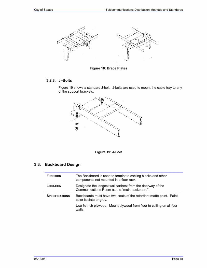
Figure 18: Brace Plates
3.2.8. J–Bolts
Figure 19 shows a standard J-bolt. J-bolts are used to mount the cable tray to any of the support brackets.
Figure 19: J-Bolt
3.3. Backboard Design
FUNCTION The Backboard is used to terminate cabling blocks and other components not mounted in a floor rack.
LOCATION Designate the longest wall farthest from the doorway of the Communications Room as the “main backboard”.
SPECIFICATIONS Backboards must have two coats of fire retardant matte paint. Paint color is slate or gray.
Use ¾-inch plywood. Mount plywood from floor to ceiling on all four walls.

City of Seattle Telecommunications Distribution Methods and Standards
05/13/05 Page 19
DESIGN LAYOUTS Two backboard design layouts: one closet supporting one floor and one closet supporting multiple floors.
Figure 20 and Figure 21 show diagrams for one closet supporting one floor:
• Data Blocks on far left.
• Jack Blocks in middle.
• Telephone Blocks right of jack blocks.
• Riser and Feed blocks on far right.
• Cable management across top of all blocks.
Cross-Connect Wire
Patch Cables
Patch Cables
PN: 107151185
PN: 107151185
PN: 107151185
PN
: 107
1511
93P
N: 1
0715
1193
PN
: 107
1511
93
PN
: 107
1511
93P
N: 1
0715
1193
PN
: 107
1511
93
PN: 1
0715
1193
PN
: 107
1511
93
Figure 20: Data Backboard Diagram (Communication Room per floor)
Figure 21: Data Backboard Diagram (Small Communication Room supporting a single floor)

City of Seattle Telecommunications Distribution Methods and Standards
05/13/05 Page 20
Figure 22 shows the diagram for one closet supporting multiple floors:
• Data blocks on top row
• Jack blocks below data blocks.
• Telephone blocks right of jack and data blocks.
• Riser and Feed blocks on far right.
• Three horizontal cable management pathways.
• Vertical cable management between each vertical row of blocks.
Cross-Connect Wire
Patch Cables
Cross-connect Wire
PN: 107151185
PN: 107151185
PN: 107151185
PN
: 107
1511
93P
N: 1
0715
1193
PN
: 107
1511
93
PN
: 107
1511
93P
N: 1
0715
1193
PN
: 107
1511
93
PN
: 107
1511
93P
N: 1
0715
1193
Figure 22: Backboard Diagram (Communication Room supporting multiple floors)
CABLE MANAGEMENT
All cables and cross-connect wire must route through horizontal and vertical cable management.
• Horizontal cable management is required at the top of every column of blocks. Depending on the number of distribution cables, recommended adding horizontal cable management in the center of the backboard.
• Vertical cable management is required on each side of the column of blocks.

City of Seattle Telecommunications Distribution Methods and Standards
05/13/05 Page 21
3.4. Cable Management
Figure 23: 900-Pair Cable Management with VisiPatch 110 Patch System
Figure 24: Vertical Cable Management with Floor Mount Racks
Figure 25: D-Rings
D-Rings are used to mount cables to the backboard. Use D-Rings when no block or rack management is available.
3.5. Equipment Rack Design
Communications equipment racks are required in the standard “walk-in” Communications Room and Entrance Room.
3.5.1. General Rack Specifications
DIMENSIONS Data Network Racks: 7’ high X 19” wide
Telephone Network Racks: 7’ high X 23” wide

City of Seattle Telecommunications Distribution Methods and Standards
05/13/05 Page 22
Fiber Riser Racks: 7’ high X 19” wide
Radio Racks: 7’ high X 19” wide
MDF Vertical Cable Management: Use double-sided wide vertical rack cabling, color: clear. Rack dimensions: 7’ high X 6” wide X 12.75” deep. (Figure 18)
IDF Vertical Cable Management: Use double-sided narrow or wide vertical rack cabling (depending on cabling quantities). Double-sided narrow, color: clear. Rack dimensions: 7’ high X 3.65” wide X 12.75” deep.
COLOR Silver Chatsworth
INSTALLATION Bolted to the floor, with seismic bracing to the cable tray above.
Ground racks to internal Communication Room ground bus.
LABELING One-inch label, placed at the top.
3.5.2. Equipment Rack Layout in Communications Rooms
All equipment racks designed for or added to Communications Rooms and Entrance Rooms must comply with the following guidelines:
• � There must be no less than 36” from the rear of rack to a blank board or wall. There must be no telephone or data blocks on the wall.
• � There must be no less than 48” from the side of the rack or row of racks to the wall.
Exceptions: The side of the rack or row of racks can be less than 36” against the wall, as long as access to the rear and front of the rack is not compromised.
• � There must be 48” clearance in front and rear of the rack if there is another row of racks or termination blocks on the wall.
• � There must be at least 6” space between racks to accommodate cable management.
The above guidelines are illustrated in Figure 26.

City of Seattle Telecommunications Distribution Methods and Standards
05/13/05 Page 23
48"36"
12" CLEARANCEFROM CABLE TRAY
TO CEILING
FRONT OF RACK
12" CABLE TRAY USEDFOR CABLING FROM
EQUIPMENT RACKS TOBACKBOARD
BACKBOARD USED BYTELEPHONE & DATA
EQUIPMENT
WALL
Figure 26: Layout of Equipment Racks in Communications Rooms
3.6. Equipment Cabinets
Communications Rooms and Entrance Rooms may use equipment cabinets to house hardware that needs to be secured in an area for reasons of public safety (i.e. for the Police Department).
3.7. Power
POWER OUTLETS
Figure 27: Power Outlet
INSTALLATION One quad 20-amp circuit for each floor mount rack.

City of Seattle Telecommunications Distribution Methods and Standards
05/13/05 Page 24
LABELING Each quad 20-amp circuit is labeled with the circuit number.
Figure 28: Power Outlet Label
3.8. Seismic Bracing
RACKS Rack seismic gusset kit: P/N 11592-101 Chatsworth Products
Rack and frame kit–Concrete: P/N 40604-001 Chatsworth Products
CABLE TRAY Double Earthquake Bracing Kit: Stabilizes cable runway hung from threaded rods. P/N 10696-001 Chatsworth Products
Channel Rack-To-Runway Mounting Plate: To secure cable runway to top of equipment racks. P/N 10595-212 Chatsworth Products
CABLES All cables must be attached to the backboard or racking by either tie wraps or a horizontal/vertical cable management system.
DATA/PHONE DEVICES
All devices must be either mounted in a rack, or braced with tie-wraps or a strap.
3.9. Grounding
Each Communication Room has at least one ground bus mounted on the wall. Each component shall have a ground to the solid copper ground bus bar.
Connect the ground copper cable to a floor mount rack using a Rack-Mount Ground Bar.

City of Seattle Telecommunications Distribution Methods and Standards
05/13/05 Page 25
Figure 29: Ground Bus
Figure 30: Ground Bus Connection

City of Seattle Telecommunications Distribution Methods and Standards
05/13/05 Page 26
4. Riser System
Each fiber cable must terminate in a fiber distribution box.
Each fiber strand must be labeled with a unique number.
No splitting fiber cables. All strands must terminate in a single FDU.
4.1. Riser Installation
Prior to installation, routing verification from the Department of Information Technology is required for location within the risers. If route and location are not verified, the installer is responsible for relocation if the placement is found to be detrimental to the future installation of cables through the riser system.
The riser cable pathway must not alternate between vertical riser sleeve locations. The cabling cannot weave in between or wrap around existing cables.
All cables must be secured to ensure there is no slippage or sagging of the installed cabling. The cable type and size will help in determining the method of securing. Securing of the cables must be consistent with the BICSI manual.
Figure 31: Cable Sock
Communications cabling must be separated and or shielded from an EMI source based upon EIA/TIA and NEC specifications.
Approved fire stop material must be installed after the cable(s) have been pulled. If the riser cable will take longer than one day to install, temporary fire stopping material must be installed prior to leaving the job site for the day.

City of Seattle Telecommunications Distribution Methods and Standards
05/13/05 Page 27
Figure 32: Riser Sleeve Fire Stopping
Installation of cables in the riser of any building must be documented with labeling consistent with this manual.
4.2. Fiber Riser
Fiber riser enters the room through a 4” sleeve, and is attached to a vertical cable tray. This fiber originates in the Main Distribution Frame (MDF), located on another floor.
Figure 33: Fiber Riser

City of Seattle Telecommunications Distribution Methods and Standards
05/13/05 Page 28
4.3. Fiber Distribution Units
Figure 34: Fiber Distribution Units
4.4. Riser Labeling
Each Fiber Distribution Unit is labeled with the FROM location, fiber type and strand count.
Figure 35: Sample Fiber Distribution Unit Label

City of Seattle Telecommunications Distribution Methods and Standards
05/13/05 Page 29
5. Horizontal Distribution System
Horizontal cabling is the part of the telecommunications cabling system that extends from the work area jack or outlet to the Intermediate Distribution Frame (IDF). This cabling is laid from the IDF “horizontally” above ceilings and under (or along) floors. Cross-connects and patch cables are also part of the horizontal cabling system.
Horizontal cabling systems are designed to allow any service to use a universal system. Primary uses are telephone and data.
5.1. Cable Systems
CABLE RUN DISTANCES
The maximum horizontal distance from the distribution termination block to the work-in area jack/outlet must not exceed 250 ft., dependent of media type. This is the distance for Category 5e copper standard, currently in use and the standard for all new cable runs.
• 3 cables per station -Mohawk or BerkTek Category 5e
• 6 cables for stations needing more that 3 cables.

City of Seattle Telecommunications Distribution Methods and Standards
05/13/05 Page 30
CABLE TRAYS Work Group Areas: Bundles of cable must be piled loosely on top of a cable tray. This allows cable to be pulled easily for extended distances. Cable bundles must never be tie-wrapped to a cable tray.
Communication Room: Cables must be tied to cable tray. Bundles of cable must be tie-wrapped at each cross-section on the cable tray (see Figure 36). The diameter of each bundle must not exceed 2”.
Figure 36: Cable Trays within Communication Room
Figure 37: Whips from Data Switch to Communication Room Main Backboard
JUMPERS/PATCH CABLE
Cable provides the link between two subsystems within the HDS.
STATION CABLE The maximum distance from the jack/outlet to the workstation must not exceed 25ft.
JACKS Surface mount boxes and faceplates: Panduit
RJ45 Jacks: Avaya
Exception: Justice Center: Ortronics

City of Seattle Telecommunications Distribution Methods and Standards
05/13/05 Page 31
WIRE BLOCK Small locations: Avaya (Lucent) 110
Medium locations: System X, Avaya VisiPatch
Large locations: System X, Avaya VisiPatch
HANGER BARS Each bundle of cable lay loosely on hanger bar.
DATA EQUIPMENT WHIPS
Cat 5e individual cables with a RJ45 connector on one end. The RJ45 connector end plugs directly into the data component. The whip end is punched down on the backboard.
PHONE EQUIPMENT WHIPS

City of Seattle Telecommunications Distribution Methods and Standards
05/13/05 Page 32
FDU
FLOOR 1
FLOOR 2
IDF
WORK AREA
WORK AREA
IDF
PBX
DATA
DATA
FDU
UTP DISTRIBUTION SYSTEM
25 pair cableColor: Slate
Category 3 Twisted Pair JumperWhite/Blue BlueWhite/Orange Orange
Category 5e Mohawk Megalan3 plenum, cables bundledCable Colors: White, Blue, Yellow
Subsystem336 Pair BaseConnecting Blocks-C4Designation CoverLabel HoldersLabelsVertical Distribution Rings
Category 5e CSRJ45-4pr whipColor: Slate or Grey
Patch Cable4 pair Gigaspeed patch cableColor: Slate
Riser CableCBL, Riser Rated, 100pr,24AWG or 22AWG
Telephone Station Cable8100-25-W, Adirondak, RJ11,6 conductor, Silver Satin
Data Station CableCategory 5e RJ45-RJ45Color: BlackRJ45258B-XXX Assy, Mod, UTP
Figure 38: Unshielded Twisted Pair Distribution System

City of Seattle Telecommunications Distribution Methods and Standards
05/13/05 Page 33
5.2. Cable Runs
The horizontal cabling system uses four-pair 100 Unshielded Twisted Pair (UTP) cable.
STANDARD • Current acceptable cable types: Ber-Tek and Mohawk.
• Category 5e
• UTP cable is restricted to four-pair size to support a broad range of applications.
• Three cables per outlet is the standard for all new locations (i.e., Key Tower, Justice Center, and City Hall).
COMPONENTS 24 AWG thermoplastic insulated solid conductors formed into four individually twisted pairs, and enclosed by a thermoplastic jacket.
COLOR CODES Pair 1: White-Blue/Blue
Pair 2: White-Orange/Orange
Pair 3: White-Green/Green
Pair 4: White-Brown/Brown
5.3. Wiring Blocks
Wiring blocks are wall-mounted using the 110 System-Lucent Systimax SCS VisiPatch Wall Mount System. This system features a unique reverse direction patch cord, integrated cable management and increased density to clean up clutter for a neat, cordless appearance.
MODEL VisiPatch Field Terminated Kit: 110UB1-336FT
VisiPatch Wall Mount Bracket: 110UP-WB (see Figure 39)
Figure 39: 110UP-WB VisiPatch Wall Mount Bracket
DIMENSIONS 21.6’ high X 8.53’ wide X 8.5’ deep
BACK PANEL This wall-mounting hardware has two identical “L” shaped halves that snap together. The back panel holds 12 wiring blocks, is stackable and provides better retention and tie down points for cable routing.

City of Seattle Telecommunications Distribution Methods and Standards
05/13/05 Page 34
WIRING BLOCK The wiring block snaps to the back panel and accepts 28 conductor pairs, three more than traditional 110 systems. Slots and grooves allow versatile cable management, keeping the cables close to the termination point and permitting technicians to maintain the tight twist of pairs required for high-speed systems. The wiring block supports seven 110C4 connecting blocks. The wiring block accepts 4 and 25 pair cables. The wiring block is included in the Field Terminated Kit.
DESIGNATION STRIPS/ COVER PLATE
The cover plate snaps directly on the wiring block and protects the termination cables. It also includes a large label-holding surface to assist with circuit identification, and serves as a positive attachment point for the latching of the 4-pair patch cord. The cover plate and the wiring block provide a built in horizontal patch and management trough. The cover plate is included in the Field Terminated Kit.
LABEL HOLDERS AND LABELS
Label holders mount onto the cover plate with an adhesive backing, and accept any of the nine colored labels. Twelve holders and 12 white labels are included in the Field Terminated Kit. Additional labels are sold separately.
HORIZONTAL AND VERTICAL MANAGEMENT
Horizontal and vertical cable managers support a maximum cable count of 900 cable pairs. Each component is sold separately.
• Horizontal Cable Manager: 64”, part number 107151185.
• Vertical Cable Manager: 21.6”, part number 107151193.
WEB SITE http://www.lucent.com/systimax/visipatch.htm
5.4. Cable Hardware to Backboard
Data hardware is cabled (whipped) to the main backboard, with individual category 5e cables.
A bundle of cables shall not cross to multiple host modules.
Separate cables in the middle of the host modules with more than 24 RJ45 ports. Purpose is to limit the quantity of cables per bundle.
Label each RJ45 cable end with the assigned switch port.
Exception: Data hardware installed inside a server cabinet does not need to be cabled to a backboard.

City of Seattle Telecommunications Distribution Methods and Standards
05/13/05 Page 35
Figure 40: Cisco 4006 Switch with 48-Port Host Modules
Figure 41: Cisco 24-Port Switch
5.5. Labeling Blocks
Blocks are labeled with a background color that identifies the system they support.
DISTRIBUTION SYSTEM
Label Color: Blue
Block Type: Jacks or floor outlets
2-001FLOOR
JACK NUMBER (3 DIGITS) MANAGEMENT SYSTEM
Label Color: Yellow
Block Type:Data switches or hubs
42-2-22FLOOR - SLOT - PORT
PBX SYSTEM Label Color: Purple
Block Type: PBX or Octel switches
RISER SYSTEM Label Color: Green
Block Type: Vertical riser cabling

City of Seattle Telecommunications Distribution Methods and Standards
05/13/05 Page 36
FEED SYSTEM Label Color: Slate
Block Type: Horizontal cabling between data closets (IDF’s)
RADIO SYSTEM Label Color: Orange
Block Type: Radio disconnect blocks
5.6. Patch System or Cross-Connects
5.6.1. VisiPatch 119 4-Pair Adapter Cords
FUNCTION Patch cables are used for all data connections, including those supporting Fast Ethernet and Gigabit Ethernet speeds.
• The 4 Pair GigaSPEED Patch Cable (plug to plug) is used for all data jacks using the VisiPatch Cable System.
• The 4 Pair GigaSPEED Patch Cable (plug to RJ45) is used to test devices (i.e., FLUKE).
STANDARD Site/building standard for all new locations (i.e., Key Tower, Justice Center, and City Hall).
COLOR Slate
FEATURES • Has a 4 pair 110 VisiPatch plug on both ends.
• Available in EIA/TIA 568B wiring, and accommodates transitioning from network equipment to the VisiPatch cross-connect field.
Figure 42: VisiPatch 119 4-Pair Adapter Cords

City of Seattle Telecommunications Distribution Methods and Standards
05/13/05 Page 37
5.6.2. VisiPatch Cable Packages
5.6.2.1. One Four-Pair VisiPatch Patch Comcodes
DESIGNATION LENGTH COMCODE
110P8UP-GS-2 2 feet 108 537 101
110P8UP-GS-3 3 feet 108 537 119
110P8UP-GS-4 4 feet 108 537 127
110P8UP-GS-5 5 feet 108 537 135
110P8UP-GS-6 6 feet 108 537 143
110P8UP-GS-7 7 feet 108 537 150
110P8UP-GS-8 8 feet 108 537 168
110P8UP-GS-9 9 feet 108 537 176
110P8UP-GS-12 12 feet 108 537 184
110P8UP-GS-15 15 feet 108 537 192
110P8UP-GS-18 18 feet 108 537 200
5.6.2.2. One Pair Cable Comcodes
DESIGNATION LENGTH COMCODE
110P2UP-GS-2 2 feet 108 535 527
110P2UP-GS-3 3 feet 108 535 576
110P2UP-GS-4 4 feet 108 535 584
110P2UP-GS-5 5 feet 108 535 592
110P2UP-GS-6 6 feet 108 535 600
110P2UP-GS-7 7 feet 108 535 618
110P2UP-GS-8 8 feet 108 535 626
110P2UP-GS-9 9 feet 108 535 634
110P2UP-GS-12 12 feet 108 535 642
110P2UP-GS-15 15 feet 108 535 659
110P2UP-GS-18 18 feet 108 535 667
5.6.2.3. Two Pair Cable Comcodes
DESIGNATION LENGTH COMCODE
110P4UP-GS-2 2 feet 108 535 675
110P4UP-GS-3 3 feet 108 535 683
110P4UP-GS-4 4 feet 108 535 691
110P4UP-GS-5 5 feet 108 535 709
110P4UP-GS-6 6 feet 108 535 717
110P4UP-GS-7 7 feet 108 535 725
110P4UP-GS-8 8 feet 108 535 733
110P4UP-GS-9 9 feet 108 535 741
110P4UP-GS-12 12 feet 108 535 758
110P4UP-GS-15 15 feet 108 535 766
110P4UP-GS-18 18 feet 108 535 774

City of Seattle Telecommunications Distribution Methods and Standards
05/13/05 Page 38
5.6.3. Cross-Connect Wire Color Codes
DATA Cross-Connect Wire 1: Red/Blue
Cross-Connect Wire 2: Red/Orange
Category 5
(100 MHz)
PHONE Cross-Connect Wire 1: White/Blue
Cross-Connect Wire 2: Blue
Category 3
(20 MHz)
PHONE Cross-Connect Wire 1: White/Blue
Cross-Connect Wire 2: White/Orange
Category 3
(20 MHz)
911 Cross-Connect Wire 1: White
Cross-Connect Wire 2: Red
Category 3
(20 MHz)
ISDN Cross-Connect Wire 1: Yellow
Cross-Connect Wire 2: Blue
Category 3
(20 MHz)
PATCH CABLE-DATACROSS-CONNECT WIRE
Figure 43: Cross-Connect Wire Diagram
5.7. Work Area Jacks/Outlets
Each four-pair cable must be terminated in an eight-position modular jack at the work area.
• A standard outlet contains a minimum of 3 jacks per single gang box.
• There must be one outlet per station.
• A single outlet can support up to a maximum of six jacks per single gang box (if needed to support additional services).
• Use a standard 8-position 568B outlet.
City of Seattle Telecommunications Distribution Methods and Standards
05/13/05 Page 39
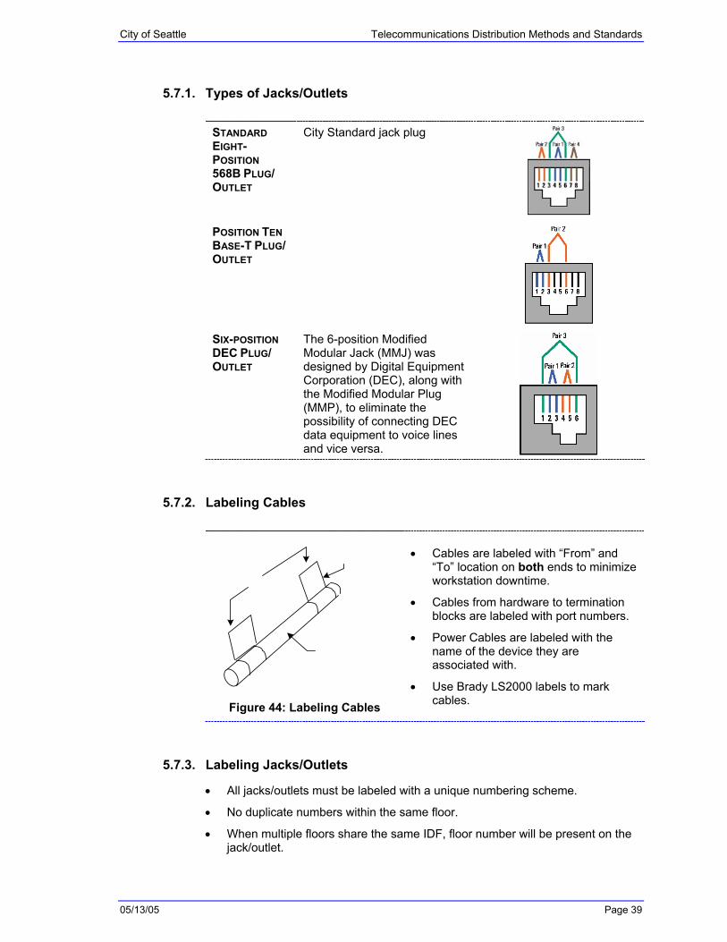
5.7.1. Types of Jacks/Outlets
STANDARD EIGHT-POSITION 568B PLUG/ OUTLET
City Standard jack plug
POSITION TEN BASE-T PLUG/ OUTLET
SIX-POSITION DEC PLUG/ OUTLET
The 6-position Modified Modular Jack (MMJ) was designed by Digital Equipment Corporation (DEC), along with the Modified Modular Plug (MMP), to eliminate the possibility of connecting DEC data equipment to voice lines and vice versa.
5.7.2. Labeling Cables
Figure 44: Labeling Cables
• Cables are labeled with “From” and “To” location on both ends to minimize workstation downtime.
• Cables from hardware to termination blocks are labeled with port numbers.
• Power Cables are labeled with the name of the device they are associated with.
• Use Brady LS2000 labels to mark cables.
5.7.3. Labeling Jacks/Outlets
• All jacks/outlets must be labeled with a unique numbering scheme.
• No duplicate numbers within the same floor.
• When multiple floors share the same IDF, floor number will be present on the jack/outlet.

City of Seattle Telecommunications Distribution Methods and Standards
05/13/05 Page 40
• When using single gang boxes, write jack/outlet numbers on top and in front of box.
• No special color scheme is used when labeling jacks/outlets.
25-001-002-003
25-004-005-006
1 2
3 4
5 6
25-001 25-002
25-003
Figure 45: Labeling Jacks/Outlets
5.8. Basic Cabling Concepts
ATTENUATION Attenuation is a decrease in strength of a signal over the length of a cable. Attenuation is caused by a loss of electrical energy due to the resistance of the wire, and/or by leakage of energy through the cable’s insulating material.
LAN CABLES LAN cables have a number of characteristics in common with other types of electrical cables. All electrical cables have continuity, which means that they serve as a complete path for electrical current flow. Each end of the cable has some connector for connecting the cable to an appropriate electrical device. Cables with multiple wires usually have a pin assignment that describes how the wires are arranged in the connectors.
NOISE Electrical noise is unwanted electrical signals that alter the shape of (distort) the signals transmitted over a LAN cable. Signals that are severely distorted by noise can cause communication errors in a LAN.
Any device that uses or generates voltages that vary over time can generate electrical noise. Power generators, electric heaters, refrigerators, elevators and fluorescent lighting devices are examples. LAN cables act as antennas that can pick up electrical noise.
TWISTED PAIR CABLES
Twisted pair cables consist of wires that twist together to minimize crosstalk between the pairs.
Each cable pair forms a complete electrical path for signal transmission. The current flowing through each wire in a twisted pair is equal, but flowing in opposite directions. These currents produce electromagnetic fields that could transmit electrical noise to nearby wires. The fields surrounding the two wires have opposite polarities. Twisting the wires together causes the fields to cancel out, thereby minimizing the electrical noise (crosstalk) generated by each cable pair.
SPLIT PAIRS A split pair occurs when one wire from a cable pair is twisted together with a wire from a different cable pair. Split pairs most frequently result from miswires at punchdown blocks and cable connectors.
Split pairs cause crosstalk because the signals in the twisted pairs come from different circuits.

City of Seattle Telecommunications Distribution Methods and Standards
05/13/05 Page 41
5.9. Cabling Guidelines
HORIZONTAL CABLING DISTANCES
• The maximum horizontal distance from the distribution termination block to the work-in area jack/outlet must not exceed 250 ft., dependent of media type. This is the distance for Category 5e copper standard, currently in use and the standard for all new cable runs.
• The maximum distance from the cabling modular plug to the distribution termination block, which include cross-connects or patch cables within the IDF must not exceed 40 ft.
• The maximum distance from the jack/outlet to the workstation must not exceed 25 ft.
CONNECTING HARDWARE
• Use connecting hardware that is compatible with the installed cable.
• Do not use connecting hardware that is of a lower category than the cable being used.
CABLE TERMINATIONS
• Terminate each horizontal cable on a dedicated telecommunications outlet.
• Do not create multiple appearances of the same cable at several distribution points (called bridged taps).
CABLE SPANS • Locate the main cross-connect near the center of the building to limit cable distances.
• Do not locate cross-connects where cable distances will exceed the recommended maximum.
TWISTED PAIRS • Maintain the twist of horizontal and backbone cable pairs up to the point of termination.
• Do not leave any wire pairs untwisted.
LAYING CABLE • Tie and dress horizontal cables neatly and with a minimum bend radius of 4 times the cable diameter.
• Do not over-tighten cable ties, use staples, or make sharp bends with cables.
DISTANCE FROM ELECTRICAL EQUIPMENT
• Place cabling at a sufficient distance from equipment.
• Do not place cable near equipment that may generate high levels of electromagnetic interference.

City of Seattle Telecommunications Distribution Methods and Standards
05/13/05 Page 42
TESTING TOOLS
Figure 46: Fluke with Remote 1
5.10. Crossover Cables
Crossover cables are used to connect data devices to each other (daisy chain). Straight-through cables are used for connecting workstations with a hub or switch.
Switch Hub
CROSSOVER CABLE
blocks blocks
STRAIGHT-THROUGH CABLE(whips)
Figure 47: Crossover Cable Diagram
5.10.1. How to Make a Crossover Cable
To make a crossover cable, you need a standard straight through UTP-Cat5, 5e, or 6 cable.
Strip at least 1 inch off the main cable insulation and carefully trim the eight internal wires using the factory-assembled end (RJ45) as a guide to the proper length. Just make sure each wire is equal length and that the connector cable lock pinches the main cable insulation.
NOTE: Even though pins 4, 7, and 8 are not used it, is mandatory that they are present in the cable.
City of Seattle Telecommunications Distribution Methods and Standards
05/13/05 Page 43
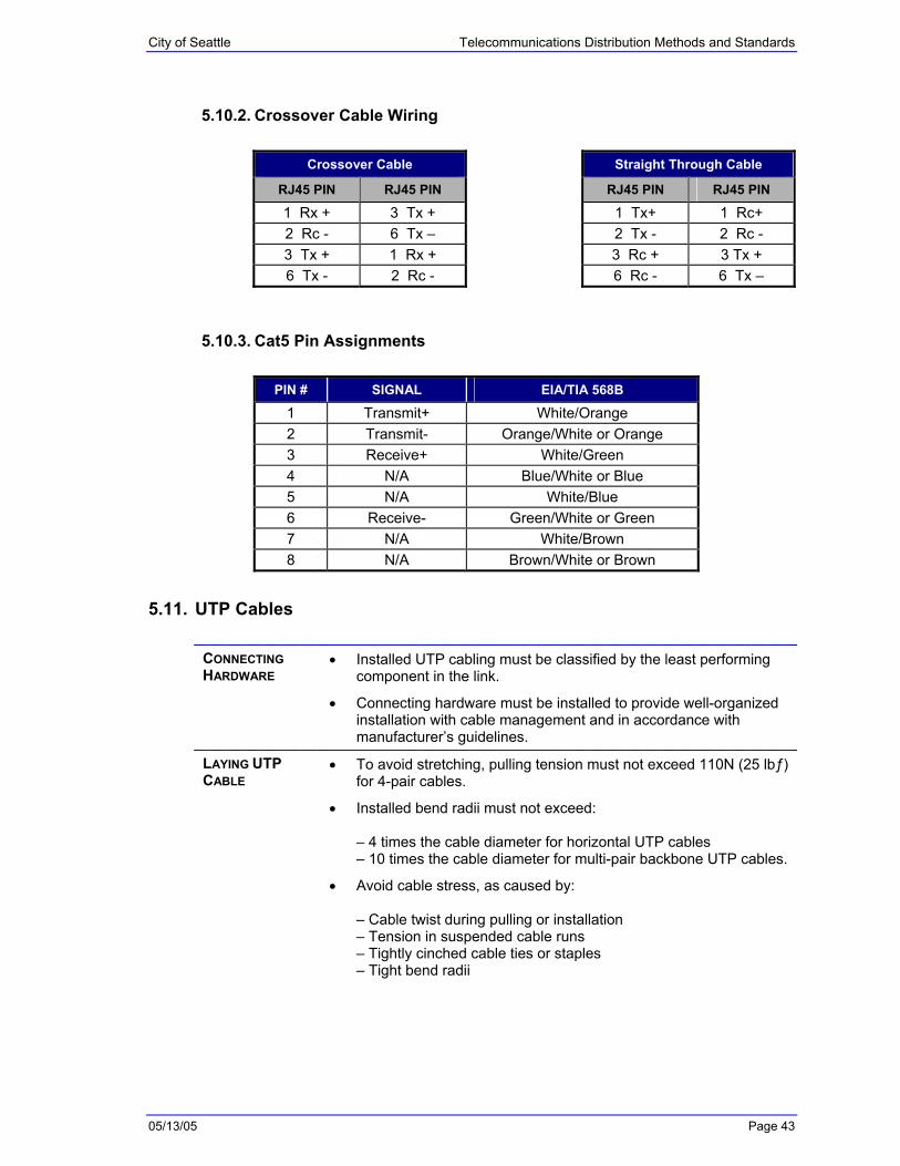
5.10.2. Crossover Cable Wiring
Crossover Cable Straight Through Cable
RJ45 PIN RJ45 PIN RJ45 PIN RJ45 PIN
1 Rx + 3 Tx + 1 Tx+ 1 Rc+ 2 Rc - 6 Tx – 2 Tx - 2 Rc - 3 Tx + 1 Rx + 3 Rc + 3 Tx + 6 Tx - 2 Rc - 6 Rc - 6 Tx –
5.10.3. Cat5 Pin Assignments
PIN # SIGNAL EIA/TIA 568B
1 Transmit+ White/Orange 2 Transmit- Orange/White or Orange 3 Receive+ White/Green 4 N/A Blue/White or Blue 5 N/A White/Blue 6 Receive- Green/White or Green 7 N/A White/Brown 8 N/A Brown/White or Brown
5.11. UTP Cables
CONNECTING HARDWARE
• Installed UTP cabling must be classified by the least performing component in the link.
• Connecting hardware must be installed to provide well-organized installation with cable management and in accordance with manufacturer’s guidelines.
LAYING UTP CABLE
• To avoid stretching, pulling tension must not exceed 110N (25 lbƒ) for 4-pair cables.
• Installed bend radii must not exceed: – 4 times the cable diameter for horizontal UTP cables – 10 times the cable diameter for multi-pair backbone UTP cables.
• Avoid cable stress, as caused by: – Cable twist during pulling or installation – Tension in suspended cable runs – Tightly cinched cable ties or staples – Tight bend radii
City of Seattle Telecommunications Distribution Methods and Standards
05/13/05 Page 44
UTP CONNECTOR TERMINATIONS
• Strip back only as much jacket as is required to terminate individual pairs.
• Pair twists must be maintained as close as possible to the point of termination.
• Untwisting must not exceed: – 25 mm (1.0 in) for category 4 links – 13 mm (0.5 in) for category 5 and category 5e links – Follow manufacturer guidelines for category 3 products – If no guidelines exist, untwisting must not exceed 75 mm (3.0 in)
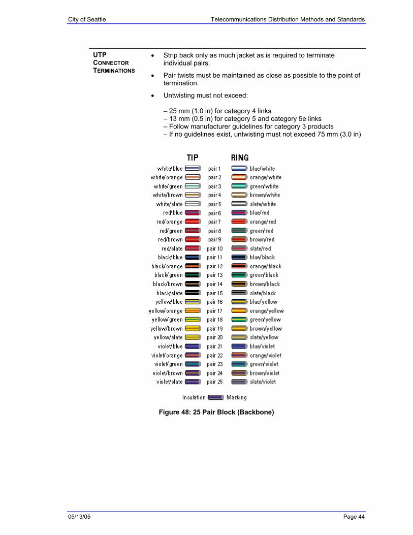
Figure 48: 25 Pair Block (Backbone)

City of Seattle Telecommunications Distribution Methods and Standards
05/13/05 Page 45
6. Glossary
A Attenuation: A decrease in the strength of a signal over the length of a cable. Attenuation is caused by a loss of electrical energy due to the resistance of the wire, and/or by leakage of energy through the cable’s insulating material.
AWG: Acronym for …
B
C Cable Management: The physical layout of cables and wires within Communications Rooms.
Crosstalk: Interference caused by two signals becoming partially superimposed on each other due to electromagnetic (inductive) or electrostatic (capacitive) coupling between the conductors carrying the signals.
D Data Backboard: …
DEC: Acronym for Digital Equipment Corporation.
DoIT: Acronym for Department of Information Technology.
E Electrical Noise: Unwanted electrical signals that alter the shape of (distort) the signals transmitted over a cable. Signals that are severely distorted by noise can cause communication errors.
Any device that uses or generates voltages that vary over time can generate electrical noise. Power generators, electric heaters, refrigerators, elevators and fluorescent lighting devices are examples.

City of Seattle Telecommunications Distribution Methods and Standards
05/13/05 Page 46
F FDU: Acronym for …
G
H
I IDF: Acronym for Intermediate Distribution Frame.
J
K KVM: Acronym for Keyboard, Video, and Mouse.
L LAN: Acronym for Local Area Network.

City of Seattle Telecommunications Distribution Methods and Standards
05/13/05 Page 47
M MDF: Acronym for Main Distribution Frame.
MMJ: Acronym for Modified Modular Jack, a jack designed by Digital Equipment Corporation to eliminate the possibility of connecting DEC data equipment to voice lines and vice versa.
MMP: Acronym for Modified Modular Plug, a plug designed by Digital Equipment Corporation to eliminate the possibility of connecting DEC data equipment to voice lines and vice versa.
N Noise: See Electrical Noise.
O
P Patch Cable: …
PBX: Acronym for …
PDU: Acronym for Power Distribution Unit.
Q
R Riser: Vertical shaft used to route cable between floors.
S

City of Seattle Telecommunications Distribution Methods and Standards
05/13/05 Page 48
SPID: Acronym for …
Split Pair: A split pair occurs when one wire from a cable pair is twisted together with a wire from a different cable pair. Split pairs most frequently result from miswires at punchdown blocks and cable connectors. Split pairs cause crosstalk because the signals in the twisted pairs come from different circuits.
T Twisted Pair Cables: Consist of wires that twist together to minimize crosstalk between the pairs.
U UTP: Acronym for Unshielded Twisted Pair.
V
W
X
Y

City of Seattle Telecommunications Distribution Methods and Standards
05/13/05 Page 49
Z